Mass Transfer Operations for the Practicing...
65
Mass Transfer Operations for the Practicing Engineer Louis Theodore Francesco Ricci
Transcript of Mass Transfer Operations for the Practicing...
Mass Transfer Operationsfor the PracticingEngineerLouis TheodoreFrancesco Ricci

Mass Transfer Operationsfor the PracticingEngineer
Mass Transfer Operationsfor the PracticingEngineerLouis TheodoreFrancesco Ricci
Copyright 2010 by John Wiley amp Sons Inc All rights reserved
Published by John Wiley amp Sons Inc Hoboken New JerseyPublished simultaneously in Canada
No part of this publication may be reproduced stored in a retrieval system or transmitted in any form or byany means electronic mechanical photocopying recording scanning or otherwise except as permittedunder Section 107 or 108 of the 1976 United States Copyright Act without either the prior writtenpermission of the publisher or authorization through payment of the appropriate per-copy fee to theCopyright Clearance Center Inc 222 Rosewood Drive Danvers MA 01923 (978) 750-8400 fax (978)750-4470 or on the web at wwwcopyrightcom Requests to the publisher for permission should beaddressed to the Permissions Department John Wiley amp Sons Inc 111 River Street Hoboken NJ 07030(201) 748-6011 fax (201) 748-6008 or online at httpwwwwileycomgopermission
Limit of LiabilityDisclaimer of Warranty While the publisher and author have used their best efforts inpreparing this book they make no representations or warranties with respect to the accuracy or completenessof the contents of this book and specifically disclaim any implied warranties of merchantability or fitness fora particular purpose No warranty may be created or extended by sales representatives or written salesmaterials The advice and strategies contained herein may not be suitable for your situation You shouldconsult with a professional where appropriate Neither the publisher nor author shall be liable for any loss ofprofit or any other commercial damages including but not limited to special incidental consequential orother damages
For general information on our other products and services or for technical support please contact ourCustomer Care Department within the United States at (800) 762-2974 outside the United States at (317)572-3993 or fax (317) 572-4002
Wiley also publishes its books in a variety of electronic formats Some content that appears in print maynot be available in electronic formats For more information about Wiley products visit our web site atwwwwileycom
Library of Congress Cataloging-in-Publication Data
Theodore LouisMass transfer operations for the practicing engineer Louis Theodore Francesco Ricci
p cmIncludes IndexISBN 978-0-470-57758-5 (hardback)
1 Engineering mathematics 2 Mass transfer I Ricci Francesco II TitleTA331T476 2010530407501512mdashdc22 2010013924
Printed in the United States of America
10 9 8 7 6 5 4 3 2 1
To Ann Cadigan and Meg Norrisfor putting up with me (LT)
and
To my mother Laura my father Josephand my brother Joseph Jr
for reasons which need not be spoken (FR)
Contents
Preface xv
Part One Introduction
1 History of Chemical Engineering and Mass Transfer Operations 3
References 5
2 Transport Phenomena vs Unit Operations Approach 7
References 10
3 Basic Calculations 11
Introduction 11Units and Dimensions 11Conversion of Units 15The Gravitational Constant gc 17Significant Figures and Scientific Notation 17References 18
4 Process Variables 19
Introduction 19Temperature 20Pressure 22Moles and Molecular Weight 23Mass Volume and Density 25Viscosity 25Reynolds Number 28pH 29Vapor Pressure 31Ideal Gas Law 31References 35
vii
5 Equilibrium vs Rate Considerations 37
Introduction 37Equilibrium 37Rate 38Chemical Reactions 39References 40
6 Phase Equilibrium Principles 41
Introduction 41Gibbrsquos Phase Rule 44Raoultrsquos Law 45Henryrsquos Law 53Raoultrsquos Law vs Henryrsquos Law 59VaporndashLiquid Equilibrium in Nonideal Solutions 61VaporndashSolid Equilibrium 64LiquidndashSolid Equilibrium 68References 69
7 Rate Principles 71
Introduction 71The Operating Line 72Fickrsquos Law 73
Diffusion in Gases 75Diffusion in Liquids 79
Mass Transfer Coefficients 80
Individual Mass Transfer Coefficients 81Equimolar Counterdiffusion 83Diffusion of Component A Through Non-diffusing Component B 84
Overall Mass Transfer Coefficients 87
Equimolar Counterdiffusion andor Diffusion in Dilute Solutions 88Gas Phase Resistance Controlling 89Liquid Phase Resistance Controlling 89Experimental Mass Transfer Coefficients 90
References 93
Part Two Applications Component and Phase Separation Processes
8 Introduction to Mass Transfer Operations 97
Introduction 97
viii Contents
Classification of Mass Transfer Operations 97
Contact of Immiscible Phases 98Miscible Phases Separated by a Membrane 101Direct Contact of Miscible Phases 102
Mass Transfer Equipment 102
Distillation 103Absorption 104Adsorption 104Extraction 104Humidification and Drying 105Other Mass Transfer Unit Operations 105The Selection Decision 106
Characteristics of Mass Transfer Operations 107
Unsteady-State vs Steady-State Operation 108Flow Pattern 109Stagewise vs Continuous Operation 116
References 117
9 Distillation 119
Introduction 119Flash Distillation 120Batch Distillation 127Continuous Distillation with Reflux 133
Equipment and Operation 133Equilibrium Considerations 140Binary Distillation Design McCabendashThiele Graphical Method 142Multicomponent Distillation FenskendashUnderwoodndashGilliland (FUG)
Method 161Packed Column Distillation 184
References 185
10 Absorption and Stripping 187
Introduction 187Description of Equipment 189
Packed Columns 189Plate Columns 196
Design and Performance EquationsmdashPacked Columns 200
Liquid Rate 200Column Diameter 207Column Height 210Pressure Drop 224
Contents ix
Design and Performance EquationsmdashPlate Columns 227Stripping 235Packed vs Plate Tower Comparison 241Summary of Key Equations 242References 243
11 Adsorption 245
Introduction 245Adsorption Classification 247
Activated Carbon 248Activated Alumina 248Silica Gel 249Molecular Sieves 249
Adsorption Equilibria 250
Freundlich Equation 253Langmuir Isotherms 253
Description of Equipment 257Design and Performance Equations 264Regeneration 283References 291
12 LiquidndashLiquid and SolidndashLiquid Extraction 293
Introduction 293LiquidndashLiquid Extraction 294
The Extraction Process 294Equipment 295Solvent Selection 298Equilibrium 300Graphical Procedures 301Analytical Procedures 304
SolidndashLiquid Extraction (Leaching) 312
Process Variables 313Equipment and Operation 315Design and Predictive Equations 317
References 325
13 Humidification and Drying 327
Introduction 327Psychrometry and the Psychrometric Chart 327Humidification 339
x Contents
Equipment 341Describing Equations 343
Drying 347
Rotary Dryers 352Spray Dryers 361
References 369
14 Crystallization 371
Introduction 371Phase Diagrams 373The Crystallization Process 379Crystal Physical Characteristics 382Equipment 391Describing Equations 393Design Considerations 397References 404
15 Membrane Separation Processes 407
Introduction 407Reverse Osmosis 408
Describing Equations 414
Ultrafiltration 420
Describing Equations 421
Microfiltration 427
Describing Equations 428
Gas Permeation 432
Describing Equations 433
References 437
16 Phase Separation Equipment 439
Introduction 439FluidndashParticle Dynamics 442GasndashSolid (GndashS) Equipment 446
Gravity Settlers 447Cyclones 449Electrostatic Precipitators 454Venturi Scrubbers 457Baghouses 461
Contents xi
GasndashLiquid (GndashL) Equipment 465LiquidndashSolid (LndashS) Equipment 467
Sedimentation 467Centrifugation 471Flotation 472
LiquidndashLiquid (LndashL) Equipment 475SolidndashSolid (SndashS) Equipment 477
High-Gradient Magnetic Separation 477Solidification 477
References 479
Part Three Other Topics
17 Other and Novel Separation Processes 483
Freeze Crystallization 484Ion Exchange 484Liquid Ion Exchange 484Resin Adsorption 485Evaporation 485Foam Fractionation 486Dissociation Extraction 486Electrophoresis 486Vibrating Screens 487References 488
18 Economics and Finance 489
Introduction 489The Need for Economic Analyses 489Definitions 491
Simple Interest 491Compound Interest 491Present Worth 492Evaluation of Sums of Money 492Depreciation 493Fabricated Equipment Cost Index 493Capital Recovery Factor 493Present Net Worth 494Perpetual Life 494Break-Even Point 495Approximate Rate of Return 495
xii Contents
Exact Rate of Return 495Bonds 496Incremental Cost 496
Principles of Accounting 496Applications 499References 511
19 Numerical Methods 513
Introduction 513Applications 514References 531
20 Open-Ended Problems 533
Introduction 533Developing Studentsrsquo Power of Critical Thinking 534Creativity 534Brainstorming 536Inquiring Minds 536Failure Uncertainty Success Are TheyRelated 537
Angels on a Pin 538Applications 539References 547
21 Ethics 549
Introduction 549Teaching Ethics 550Case Study Approach 551Integrity 553Moral Issues 554Guardianship 556Engineering and Environmental Ethics 557Future Trends 559Applications 561References 563
22 Environmental Management and Safety Issues 565
Introduction 565Environmental Issues of Concern 566Health Risk Assessment 568
Risk Evaluation Process for Health 570
Contents xiii
Hazard Risk Assessment 571
Risk Evaluation Process for Accidents 572
Applications 574References 591
Appendix
Appendix A Units 595
A1 The Metric System 595A2 The SI System 597A3 Seven Base Units 597A4 Two Supplementary Units 598A5 SI Multiples and Prefixes 599A6 Conversion Constants (SI) 599A7 Selected Common Abbreviations 603
Appendix B Miscellaneous Tables 605
Appendix C Steam Tables 615
Index 623
xiv Contents
Preface
Mass transfer is one of the basic tenets of chemical engineering and contains manypractical concepts that are utilized in countless industrial applications Thereforethe authors considered writing a practical text The text would hopefully serve as atraining tool for those individuals in academia and industry involved with masstransfer operations Although the literature is inundated with texts emphasizingtheory and theoretical derivations the goal of this text is to present the subject froma strictly pragmatic point-of-view
The book is divided into three parts Introduction Applications and OtherTopics The first part provides a series of chapters concerned with principles thatare required when solvingmost engineering problems including those in mass transferoperations The second part deals exclusively with specific mass transfer operationseg distillation absorption and stripping adsorption and so on The last partprovides an overview of ABET (Accreditation Board for Engineering andTechnology) related topics as they apply to mass transfer operations plus novelmass transfer processes An Appendix is also included An outline of the topicscovered can be found in the Table of Contents
The authors cannot claim sole authorship to all of the essay material andillustrative examples in this text The present book has evolved from a host of sourcesincluding notes homework problems and exam problems prepared by several facultyfor a required one-semester three-credit ldquoPrinciples III Mass Transferrdquo undergradu-ate course offered at Manhattan College L Theodore and J Barden ldquoMass TransferrdquoATheodore Tutorial East Williston NY 1994 J Reynolds J Jeris and L TheodoreldquoHandbook of Chemical and Environmental Engineering Calculationsrdquo John Wileyamp Sons Hoboken NJ 2004 and J Santoleri J Reynolds and L TheodoreldquoIntroduction to Hazardous Waste Managementrdquo 2nd edition John Wiley amp SonsHoboken NJ 2000 Although the bulk of the problems are original andor takenfrom sources that the authors have been directly involved with every effort hasbeen made to acknowledge material drawn from other sources
It is hoped that we have placed in the hands of academic industrial andgovernment personnel a book that covers the principles and applications of masstransfer in a thorough and clear manner Upon completion of the text the readershould have acquired not only a working knowledge of the principles of mass transferoperations but also experience in their application and the reader should find him-selfherself approaching advanced texts engineering literature and industrial appli-cations (even unique ones) with more confidence We strongly believe that whileunderstanding the basic concepts is of paramount importance this knowledge may
xv
be rendered virtually useless to an engineer if heshe cannot apply these concepts toreal-world situations This is the essence of engineering
Last but not least we believe that this modest work will help the majority of indi-viduals working andor studying in the field of engineering to obtain a more completeunderstanding of mass transfer operations If you have come this far and read throughmost of the Preface you have more than just a passing interest in this subject Westrongly suggest that you try this text we think you will like it
Our sincere thanks are extended to Dr Paul Marnell at Manhattan College for hisinvaluable help in contributing to Chapter 9 on Distillation and Chapter 14 onCrystallization Thanks are also due to Anne Mohan for her assistance in preparingthe first draft of Chapter 13 (Humidification and Drying) and to Brian Berminghamand Min Feng Zheng for their assistance during the preparation of Chapter 12(LiquidndashLiquid and SolidndashLiquid Extraction) Finally Shannon OrsquoBrien KathrynScherpf and Kimberly Valentine did an exceptional job in reviewing the manuscriptand page proofs
FRANCESCO RICCI
April 2010 LOUIS THEODORE
NOTE An additional resource is available for this text An accompanying websitecontains over 200 additional problems and 15 hours of exams solutions for theproblems and exams are available at wwwwileycom for those who adopt the bookfor training andor academic purposes
xvi Preface
Part One
IntroductionThe purpose of this Part can be found in its title The book itself offers the readerthe fundamentals of mass transfer operations with appropriate practical applicationsand serves as an introduction to the specialized and more sophisticated texts in thisarea The reader should realize that the contents are geared towards practitioners inthis field as well as students of science and engineering not chemical engineers perse Simply put topics of interest to all practicing engineers have been includedFinally it should alsobenoted that themicroscopic approachofmass transferoperationsis not treated in any requiredundergraduateManhattanCollegeofferingTheManhattanapproach is to place more emphasis on real-world and design applications Howevermicroscopic approachmaterial is available in the literature as noted in the ensuing chap-ters The decision on whether to include the material presented ultimately depends onthe reader andor the approach and mentality of both the instructor and the institution
A general discussion of the philosophy and the contents of this introductorysection follows
Since the chapters in this Part provide an introduction and overview of mass trans-fer operations there is some duplication due to the nature of the overlapping nature ofoverviewintroductory material particularly those dealing with principles Part Onechapter contents include
1 History of Chemical Engineering and Mass Transfer Operations
2 Transport Phenomena vs Unit Operations Approach
3 Basic Calculations
4 Process Variables
5 Equilibrium vs Rate Considerations
6 Phase Equilibrium Principles
7 Rate Principles
Topics covered in the first two introductory chapters include a history of chemicalengineering and mass transfer operations and a discussion of transport phenomenavs unit operations The remaining chapters are concerned with introductoryengineering principles The next Part is concerned with describing and designingthe various mass transfer unit operations and equipment
Mass Transfer Operations for the Practicing Engineer By Louis Theodore and Francesco RicciCopyright 2010 John Wiley amp Sons Inc
1
Chapter 1
History of ChemicalEngineering and MassTransfer Operations
A discussion on the field of chemical engineering is warranted before proceeding tosome specific details regarding mass transfer operations (MTO) and the contents ofthis first chapter A reasonable question to ask is What is Chemical EngineeringAn outdated but once official definition provided by the American Institute ofChemical Engineers is
Chemical Engineering is that branch of engineering concerned with the developmentand application of manufacturing processes in which chemical or certain physicalchanges are involved These processes may usually be resolved into a coordinated seriesof unit physical ldquooperationsrdquo (hence part of the name of the chapter and book) and chemicalprocesses The work of the chemical engineer is concerned primarily with the designconstruction and operation of equipment and plants in which these unit operations andprocesses are applied Chemistry physics and mathematics are the underlying sciences ofchemical engineering and economics is its guide in practice
The above definition was appropriate up until a few decades ago when the professionbranched out from the chemical industry Today that definition has changedAlthough it is still based on chemical fundamentals and physical principles these prin-ciples have been de-emphasized in order to allow for the expansion of the profession toother areas (biotechnology semiconductors fuel cells environment etc) These areasinclude environmental management health and safety computer applications andeconomics and finance This has led to many new definitions of chemical engineeringseveral of which are either too specific or too vague A definition proposed here issimply that ldquoChemical Engineers solve problemsrdquo Mass transfer is the one subjectarea that somewhat uniquely falls in the domain of the chemical engineer It isoften presented after fluid flow(1) and heat transfer(2) since fluids are involved aswell as heat transfer and heat effects can become important in any of the mass transferunit operations
Mass Transfer Operations for the Practicing Engineer By Louis Theodore and Francesco RicciCopyright 2010 John Wiley amp Sons Inc
3
A classical approach to chemical engineering education which is still usedtoday has been to develop problem solving skills through the study of severaltopics One of the topics that has withstood the test of time is mass transfer operationsthe area that this book is concerned with In many mass transfer operations onecomponent of a fluid phase is transferred to another phase because the componentis more soluble in the latter phase The resulting distribution of components betweenphases depends upon the equilibrium of the system Mass transfer operations may alsobe used to separate products (and reactants) and may be used to remove byproductsor impurities to obtain highly pure products Finally it can be used to purify rawmaterials
Although the chemical engineering profession is usually thought to haveoriginated shortly before 1900 many of the processes associated with this disciplinewere developed in antiquity For example filtration operations were carried out5000 years ago by the Egyptians MTOs such as crystallization precipitation anddistillation soon followed During this period other MTOs evolved from a mixtureof craft mysticism incorrect theories and empirical guesses
In a very real sense the chemical industry dates back to prehistoric times whenpeople first attempted to control and modify their environment The chemical industrydeveloped as did any other trade or craft With little knowledge of chemical scienceand no means of chemical analysis the earliest chemical ldquoengineersrdquo had to rely onprevious art and superstition As one would imagine progress was slow This changedwith time The chemical industry in the world today is a sprawling complex ofraw-material sources manufacturing plants and distribution facilities which supplysociety with thousands of chemical products most of which were unknown over acentury ago In the latter half of the nineteenth century an increased demand arosefor engineers trained in the fundamentals of chemical processes This demand wasultimately met by chemical engineers
The first attempt to organize the principles of chemical processing and to clarifythe professional area of chemical engineering was made in England by George EDavis In 1880 he organized a Society of Chemical Engineers and gave a series oflectures in 1887 which were later expanded and published in 1901 as A Handbookof Chemical Engineering In 1888 the first course in chemical engineering in theUnited States was organized at the Massachusetts Institute of Technology byLewis M Norton a professor of industrial chemistry The course applied aspects ofchemistry and mechanical engineering to chemical processes(3)
Chemical engineering began to gain professional acceptance in the early years ofthe twentieth century The American Chemical Society had been founded in 1876 andin 1908 it organized a Division of Industrial Chemists and Chemical Engineers whileauthorizing the publication of the Journal of Industrial and Engineering ChemistryAlso in 1908 a group of prominent chemical engineers met in Philadelphia andfounded the American Institute of Chemical Engineers(3)
The mold for what is now called chemical engineering was fashioned at the 1922meeting of the American Institute of Chemical Engineers when A D Littlersquos commit-tee presented its report on chemical engineering education The 1922 meeting markedthe official endorsement of the unit operations concept and saw the approval of a
4 Chapter 1 History of Chemical Engineering and Mass Transfer Operations
ldquodeclaration of independencerdquo for the profession(3) A key component of this reportincluded the following
Any chemical process on whatever scale conducted may be resolved into acoordinated series of what may be termed ldquounit operationsrdquo as pulverizing mixingheating roasting absorbing precipitation crystallizing filtering dissolving and so onThe number of these basic unit operations is not very large and relatively few of themare involved in any particular process An ability to cope broadly and adequately with thedemands of this (the chemical engineerrsquos) profession can be attained onlythrough the analysis of processes into the unit actions as they are carried out on thecommercial scale under the conditions imposed by practice
It also went on to state that
Chemical Engineering as distinguished from the aggregate number of subjectscomprised in courses of that name is not a composite of chemistry and mechanical andcivil engineering but is itself a branch of engineering
A time line diagram of the history of chemical engineering between theprofessionrsquos founding to the present day is shown in Figure 11(3) As can be seenfrom the time line the profession has reached a crossroads regarding the future edu-cationcurriculum for chemical engineers This is highlighted by the differences ofTransport Phenomena and Unit Operations a topic that is treated in the next chapter
REFERENCES
1 P ABULENCIA and L THEODORE ldquoFluid Flow for the Practicing Engineerrdquo JohnWiley amp Sons HobokenNJ 2009
2 L THEODORE ldquoHeat Transfer for the Practicing Engineerrdquo John Wiley amp Sons Hoboken NJ 2011(in preparation)
3 N SERINO ldquo2005 Chemical Engineering 125th Year Anniversary Calendarrdquo term project submitted toL Theodore 2004
4 R BIRD W STEWART and E LIGHTFOOT ldquoTransport Phenomenardquo 2nd edition John Wiley amp SonsHoboken NJ 2002
NOTE Additional problems are available for all readers at wwwwileycom Followlinks for this title These problems may be used for additional review homeworkandor exam purposes
History of Chemical Engineering and Mass Transfer Operations 5
1880
Geo
rge
Dav
is
prop
oses
a
ldquoSoc
iety
of
Che
mic
al
Eng
inee
rsrdquo i
n E
ngla
nd
Geo
rge
Dav
ispr
ovid
es th
e bl
uepr
int
for
a ne
w p
rofe
ssio
nw
ith 1
2 le
ctur
es o
nC
hem
ical
Eng
inee
ring
in M
anch
este
rE
ngla
nd
The
Mas
sach
uset
tsIn
stitu
te o
fTe
chno
logy
begi
ns ldquo
Cou
rse
Xrdquo
the
first
four
-ye
ar C
hem
ical
Eng
inee
ring
prog
ram
in th
eU
nite
d S
tate
s
The
Mas
sach
uset
tsIn
stitu
te o
fTe
chno
logy
sta
rts
an In
depe
nden
tD
epar
tmen
t of
Che
mic
alE
ngin
eerin
g
Pen
nsyl
vani
aU
nive
rsity
begi
ns it
sC
hem
ical
Eng
inee
ring
curr
icul
um
Tula
nebe
gins
its
Che
mic
alE
ngin
eerin
gcu
rric
ulum
Man
hatta
nC
olle
ge b
egin
sits
Che
mic
alE
ngin
eerin
gcu
rric
ulum
A
dopt
ion
of th
eR
Bird
et a
lldquoT
rans
port
Phe
nom
enardquo
appr
oach
(4)
AB
ET
str
esse
son
ce a
gain
the
emph
asis
on
the
prac
tical
des
ign
appr
oach
Uni
t Ope
ratio
nsvs
Tran
spor
tP
heno
men
ath
e pr
ofes
sion
at a
cro
ssro
ad
Will
iam
H W
alke
ran
d W
arre
n K
Le
wis
tw
opr
omin
ent
prof
esso
rs
esta
blis
h a
Sch
ool o
fC
hem
ical
Eng
inee
ring
Pra
ctic
e
The
Am
eric
anIn
stitu
te o
fC
hem
ical
Eng
inee
rsis
form
ed
1888
1892
1894
1908
1916
1920
1960
1990
Toda
y
Figure11
Chemicalengineeringtim
elin
e(3)
6
Chapter 2
Transport Phenomena vs UnitOperations Approach
The history of Unit Operations is interesting As indicated in the previous chapterchemical engineering courses were originally based on the study of unit processesandor industrial technologies However it soon became apparent that the changesproduced in equipment from different industries were similar in nature ie therewas a commonality in the mass transfer operations in the petroleum industry as withthe utility industry These similar operations became known as Unit OperationsThis approach to chemical engineering was promulgated in the Little report discussedearlier and has with varying degrees and emphasis dominated the profession tothis day
The Unit Operations approach was adopted by the profession soon after itsinception During the 130 years (since 1880) that the profession has been in existenceas a branch of engineering societyrsquos needs have changed tremendously and so haschemical engineering
The teaching of Unit Operations at the undergraduate level has remained rela-tively unchanged since the publication of several early- to mid-1900 texts Howeverby the middle of the 20th century there was a slow movement from the unit operationconcept to a more theoretical treatment called transport phenomena or more simplyengineering science The focal point of this science is the rigorous mathematicaldescription of all physical rate processes in terms of mass heat or momentum crossingphase boundaries This approach took hold of the educationcurriculum of theprofession with the publication of the first edition of the Bird et al book(1) Someincluding both authors of this text feel that this concept set the profession back severaldecades since graduating chemical engineers in terms of training were more appliedphysicists than traditional chemical engineers There has fortunately been a return tothe traditional approach to chemical engineering primarily as a result of the efforts ofABET (Accreditation Board for Engineering and Technology) Detractors to thispragmatic approach argue that this type of theoretical education experience providesanswers to what and how but not necessarily why ie it provides a greater under-standing of both fundamental physical and chemical processes However in terms
Mass Transfer Operations for the Practicing Engineer By Louis Theodore and Francesco RicciCopyright 2010 John Wiley amp Sons Inc
7
of reality nearly all chemical engineers are now presently involved with the whyquestions Therefore material normally covered here has been replaced in part witha new emphasis on solving design and open-ended problems this approach isemphasized in this text
The following paragraphs attempt to qualitatively describe the differencesbetween the above two approaches Both deal with the transfer of certain quantities(momentum energy and mass) from one point in a system to another There arethree basic transport mechanisms which can potentially be involved in a processThey are
1 Radiation
2 Convection
3 Molecular Diffusion
The first mechanism radiative transfer arises as a result of wave motion and is notconsidered since it may be justifiably neglected in most engineering applicationsThe second mechanism convective transfer occurs simply because of bulk motionThe final mechanism molecular diffusion can be defined as the transport mechanismarising as a result of gradients For example momentum is transferred in the presenceof a velocity gradient energy in the form of heat is transferred because of a temperaturegradient and mass is transferred in the presence of a concentration gradient Thesemolecular diffusion effects are described by phenomenological laws(1)
Momentum energy and mass are all conserved As such each quantity obeys theconservation law within a system
quantityinto
system
8lt
9=
quantityout ofsystem
8lt
9=thorn
quantitygenerated in
system
8lt
9= frac14
quantityaccumulatedin system
8lt
9= (21)
This equation may also be written on a time rate basis
rateinto
system
8lt
9=
rateout ofsystem
8lt
9=thorn
rategenerated in
system
8lt
9= frac14
rateaccumulatedin system
8lt
9= (22)
The conservation law may be applied at the macroscopic microscopic ormolecular level
One can best illustrate the differences in these methods with an example Considera system in which a fluid is flowing through a cylindrical tube (see Fig 21) and definethe system as the fluid contained within the tube between points 1 and 2 at any time Ifone is interested in determining changes occurring at the inlet and outlet of a systemthe conservation law is applied on a ldquomacroscopicrdquo level to the entire system Theresultant equation (usually algebraic) describes the overall changes occurring to thesystem (or equipment) This approach is usually applied in the Unit Operation
8 Chapter 2 Transport Phenomena vs Unit Operations Approach
(or its equivalent) courses an approach which is highlighted in this text and itstwo companion texts(23)
In the microscopictransport phenomena approach detailed information con-cerning the behavior within a system is required this is occasionally requested ofand by the engineer The conservation law is then applied to a differential elementwithin the system that is large compared to an individual molecule but small com-pared to the entire system The resulting differential equation is then expanded viaan integration in order to describe the behavior of the entire system
The molecular approach involves the application of the conservation laws toindividual molecules This leads to a study of statistical and quantum mechanicsmdashboth of which are beyond the scope of this text In any case the description at themolecular level is of little value to the practicing engineer However the statisticalaveraging of molecular quantities in either a differential or finite element within asystem can lead to a more meaningful description of the behavior of a system
Both the microscopic and molecular approaches shed light on the physicalreasons for the observed macroscopic phenomena Ultimately however for the practi-cing engineer these approaches may be valid but are akin to attempting to kill a flywith a machine gun Developing and solving these equations (in spite of the adventof computer software packages) is typically not worth the trouble
Traditionally the applied mathematician has developed differential equationsdescribing the detailed behavior of systems by applying the appropriate conser-vation law to a differential element or shell within the system Equations were derivedwith each new application The engineer later removed the need for these tediousand error-prone derivations by developing a general set of equations that couldbe used to describe systems These have come to be referred to by many as thetransport equations In recent years the trend toward expressing these equations invector form has gained momentum (no pun intended) However the shell-balanceapproach has been retained in most texts where the equations are presented incomponential form ie in three particular coordinate systemsmdashrectangular cylindri-cal and spherical The componential terms can be ldquolumpedrdquo together to produce amore concise equation in vector form The vector equation can be in turn re-expandedinto other coordinate systems This information is available in the literature(14)
Fluid in
1 2
1 2
Fluid out
Figure 21 Flow system
Transport Phenomena vs Unit Operations Approach 9
ILLUSTRATIVE EXAMPLE 21
Explain why the practicing engineerscientist invariably employs the macroscopic approach inthe solution of real world problems
SOLUTION The macroscopic approach involves examining the relationship betweenchanges occurring at the inlet and the outlet of a system This approach attempts to identifyand solve problems found in the real world and is more straightforward than and preferableto the more involved microscopic approach The microscopic approach which requires anunderstanding of all internal variations taking placewithin the system that can lead up to an over-all system result simply may not be necessary B
REFERENCES
1 R BIRD W STEWART and E LIGHTFOOT ldquoTransport Phenomenardquo John Wiley amp Sons HobokenNJ 1960
2 L THEODORE ldquoHeat Transfer for the Practicing Engineerrdquo John Wiley amp Sons Hoboken NJ 2011(in preparation)
3 P ABULENCIA and L THEODORE ldquoFluid Flow for the Practicing Engineerrdquo JohnWiley amp Sons HobokenNJ 2009
4 L THEODORE ldquoIntroduction to Transport Phenomenardquo International Textbook Co Scranton PA 1970
NOTE Additional problems are available for all readers at wwwwileycom Followlinks for this title These problems may be used for additional review homeworkandor exam purposes
10 Chapter 2 Transport Phenomena vs Unit Operations Approach
Chapter 3
Basic Calculations
INTRODUCTION
This chapter provides a review of basic calculations and the fundamentals ofmeasurement Four topics receive treatment
1 Units and Dimensions
2 Conversion of Units
3 The Gravitational Constant gc4 Significant Figures and Scientific Notation
The reader is directed to the literature in the Reference section of this chapter(1ndash3) foradditional information on these four topics
UNITS AND DIMENSIONS
The units used in this text are consistent with those adopted by the engineeringprofession in the United States For engineering work SI (Systeme International)and English units are most often employed In the United States the English engineer-ing units are generally used although efforts are still underway to obtain universaladoption of SI units for all engineering and science applications The SI units havethe advantage of being based on the decimal system which allows for more con-venient conversion of units within the system There are other systems of unitssome of the more common of these are shown in Table 31 Although English engin-eering units will primarily be used Tables 32 and 33 present units for both theEnglish and SI systems respectively Some of the more common prefixes for SIunits are given in Table 34 (see also Appendix A5) and the decimal equivalentsare provided in Table 35 Conversion factors between SI and English units andadditional details on the SI system are provided in Appendices A and B
Mass Transfer Operations for the Practicing Engineer By Louis Theodore and Francesco RicciCopyright 2010 John Wiley amp Sons Inc
11
Tab
le31
Com
mon
Systemsof
Units
System
Length
Tim
eMass
Force
Energy
Tem
perature
SI
meter
second
kilogram
New
ton
Joule
Kelvin
degree
Celsius
egs
centim
eter
second
gram
dyne
ergJouleor
calorie
Kelvin
degree
Celsius
fps
foot
second
pound
poundal
foot
poundal
degree
Rankined
egree
Fahrenheit
American
Engineering
foot
second
pound
pound(force)
Britishthermalunit
horsepow
er hour
degree
Rankined
egree
Fahrenheit
BritishEngineering
foot
second
slug
pound(force)
Britishthermalunit
foot
pound(force)
degree
Rankined
egree
Fahrenheit
12
Table 32 English Engineering Units
Physical quantity Name of unit Symbol for unit
Length foot ftTime second minute hour s min hMass pound (mass) lbTemperature degree Rankine 8RTemperature (alternative) degree Fahrenheit 8FMoles pound mole lbmolEnergy British thermal unit BtuEnergy (alternative) horsepower hour hp hForce pound (force) lbfAcceleration foot per second square fts2
Velocity foot per second ftsVolume cubic foot ft3
Area square foot ft2
Frequency cycles per second Hertz cycless HzPower horsepower Btu per second hp BtusHeat capacity British thermal unit per (pound
mass degree Rankine)Btulb 8R
Density pound (mass) per cubic foot lbft3
Pressure pound (force) per square inch psipound (force) per square foot psfatmospheres atmbar bar
Table 33 SI Units
Physical unit Name of unit Symbol for unit
Length meter mMass kilogram gram kg gTime second sTemperature Kelvin KTemperature (alternative) degree Celsius 8CMoles gram mole gmolEnergy Joule J kg m2s2
Force Newton N kg ms2 JmAcceleration meters per second squared ms2
Pressure Pascal Newton per square meter Pa Nm2
Pressure (alternative) bar barVelocity meters per second msVolume cubic meters liters m3 LArea square meters m2
Frequency Hertz Hz cyclessPower Watt W kg m2 s3 JsHeat capacity Joule per kilogram Kelvin Jkg KDensity kilogram per cubic meter kgm3
Angular velocity radians per second rads
Table 35 Decimal Equivalents
Inch in fractions Decimal equivalent Millimeter equivalent
A 4ths and 8ths18 0125 317514 0250 635038 0375 952512 0500 1270058 0625 1587534 0750 1905078 0875 22225B 16ths116 00625 1588316 01875 4763516 03125 7938716 04375 11113916 05625 142881116 06875 174631316 08125 206381516 09375 23813C 32nds132 003125 0794332 009375 2381
(Continued)
Table 34 Prefixes for SI Units
Multiplication factors Prefix Symbol
1000000000000000000 frac14 1018 exa E1000000000000000 frac14 1015 peta P
1000000000000 frac14 1012 tera T1000000000 frac14 109 giga G
1000000 frac14 106 mega M1000 frac14 103 kilo k100 frac14 102 hecto h10 frac14 101 deka da01 frac14 1021 deci d001 frac14 1022 centi c
0001 frac14 1023 milli m0000 001 frac14 1026 micro m
0000 000 001 frac14 1029 nano n0000 000 000 001 frac14 10212 pico p
0000 000 000 000 001 frac14 10215 femto f0000 000 000 000 000 001 frac14 10218 atto a
14 Chapter 3 Basic Calculations
Two units that appear in dated literature are the poundal and slug By definitionone poundal force will give a 1 pound mass an acceleration of 1 fts2 Alternatively1 slug is defined as the mass that will accelerate 1 fts2 when acted upon by a1 pound force thus a slug is equal to 322 pounds mass
CONVERSION OF UNITS
Converting a measurement from one unit to another can conveniently be accomplishedby using unit conversion factors these factors are obtained from a simple equation thatrelates the two units numerically For example from
12 inches (in) frac14 1 foot (ft) (31)
the following conversion factor can be obtained
12 in=1ft frac14 1 (32)
Since this factor is equal to unity multiplying some quantity (eg 18 ft) by this factorcannot alter its value Hence
18 ft (12 in=1 ft) frac14 216 in (33)
Note that in Equation (33) the old units of feet on the left-hand side cancel out leavingonly the desired units of inches
Physical equations must be dimensionally consistent For the equality to holdeach additive term in the equation must have the same dimensions This conditioncan be and should be checked when solving engineering problems Throughout the
TABLE 35 Continued
Inch in fractions Decimal equivalent Millimeter equivalent
532 015625 3969732 021875 5556932 028125 71441132 034375 87311332 040625 103191532 046875 119061732 053125 134941932 059375 150812132 065625 166692332 071875 182562532 078125 198442732 084375 214312932 090625 230193132 096875 24606
Conversion of Units 15
text great care is exercised in maintaining the dimensional formulas of all terms andthe dimensional homogeneity of each equation Equations will generally be developedin terms of specific units rather than general dimensions eg feet rather than lengthThis approach should help the reader to more easily attach physical significance to theequations presented in these chapters
Consider now the example of calculating the perimeter P of a rectangle withlength L and height H Mathematically this may be expressed as P frac14 2L thorn 2HThis is about as simple a mathematical equation that one can find However it onlyapplies when P L and H are expressed in the same units
Terms in equations must be consistent from a ldquomagnituderdquo viewpoint(3)
Differential terms cannot be equated with finite or integral terms Care should alsobe exercised in solving differential equations In order to solve differential equationsto obtain a description of the pressure temperature composition etc of a system it isnecessary to specify boundary andor initial conditions (B ao IC) for the system Thisinformation arises from a description of the problem or the physical situation Thenumber of boundary conditions (BC) that must be specified is the sum of the highestorder derivative for each independent differential equation A value of the solution onthe boundary of the system is one type of boundary condition The number of initialconditions (IC) that must be specified is the highest order time derivative appearing inthe differential equation The value for the solution at time equal to zero constitutes aninitial condition For example the equation
d2CA
dz2frac14 0 CA frac14 concentration (34)
requires 2 BCs (in terms of the position variable z) The equation
dCA
dtfrac14 0 t frac14 time (35)
requires 1 IC And finally the equation
CA
tfrac14 D
2CA
y2(36)
requires 1 IC and 2 BCs (in terms of the position variable y)
ILLUSTRATIVE EXAMPLE 31
Convert units of acceleration in cms2 to milesyr2
SOLUTION The procedure outlined on the previous page is applied to the units of cms2
1 cms2
36002 s2
1 h2
242 h2
1 day2
3652 day2
1 yr2
1 in
254 cm
1 ft12 in
1mile5280 ft
frac14 618 109 miles=yr2
Thus 10 cms2 is equal to 618 109 milesyr2 B
16 Chapter 3 Basic Calculations
THE GRAVITATIONAL CONSTANT gc
The momentum of a system is defined as the product of the mass and velocity of thesystem
Momentum frac14 (mass)(velocity) (37)
A commonly employed set of units for momentum are therefore lb fts The units ofthe time rate of change of momentum (hereafter referred to as rate of momentum) aresimply the units of momentum divided by time ie
Rate of momentum lb fts2
(38)
The above units can be converted to units of pound force (lbf) if multiplied by anappropriate constant As noted earlier a conversion constant is a term that is usedto obtain units in a more convenient form all conversion constants have magnitudeand units in the term but can also be shown to be equal to 10 (unity) with no units(ie dimensionless)
A defining equation is
1 lbf frac14 322lb fts2
(39)
If this equation is divided by lbf one obtains
10 frac14 322lb ftlbf s2 (310)
This serves to define the conversion constant gc If the rate of momentum is dividedby gc as 322 lb ftlbf s
2mdashthis operation being equivalent to dividing by 10mdashthefollowing units result
Rate of momentum lb fts2
lbf s2lb ft
lbf
(311)
One can conclude from the above dimensional analysis that a force is equivalent to arate of momentum
SIGNIFICANT FIGURES AND SCIENTIFICNOTATION(3)
Significant figures provide an indication of the precision with which a quantity ismeasured or known The last digit represents in a qualitative sense some degree ofdoubt For example a measurement of 832 inches implies that the actual quantityis somewhere between 8315 and 8325 inches This applies to calculated andmeasured quantities quantities that are known exactly (eg pure integers) have aninfinite number of significant figures
The significant digits of a number are the digits from the first nonzero digit on theleft to either (a) the last digit (whether it is nonzero or zero) on the right if there is a
Significant Figures and Scientific Notation 17
decimal point or (b) the last nonzero digit of the number if there is no decimal pointFor example
370370370028070003700370002807
has 2 significant figureshas 3 significant figureshas 4 significant figureshas 4 significant figureshas 2 significant figureshas 3 significant figureshas 4 significant figures
Whenever quantities are combined by multiplication andor division the number ofsignificant figures in the result should equal the lowest number of significant figuresof any of the quantities In long calculations the final result should be rounded offto the correct number of significant figures When quantities are combined by additionandor subtraction the final result cannot be more precise than any of the quantitiesadded or subtracted Therefore the position (relative to the decimal point) of thelast significant digit in the number that has the lowest degree of precision is the positionof the last permissible significant digit in the result For example the sum of 3702370 0037 4 and 37 should be reported as 4110 (without a decimal) The least pre-cise of the five numbers is 370 which has its last significant digit in the tens positionThe answer should also have its last significant digit in the tens position
Unfortunately engineers and scientists rarely concern themselves with significantfigures in their calculations However it is recommendedmdashat least for this chaptermdashthat the reader attempt to follow the calculational procedure set forth in this section
In the process of performing engineering calculations very large and very smallnumbers are often encountered A convenient way to represent these numbers is to usescientific notation Generally a number represented in scientific notation is the productof a number (10 but or frac14 1) and 10 raised to an integer power For example
28070000000 frac14 2807 1010
0000 002 807 frac14 2807 106
A positive feature of using scientific notation is that only the significant figures needappear in the number
REFERENCES
1 D GREEN and R PERRY (eds) ldquoPerryrsquos Chemical Engineersrsquo Handbookrdquo 8th edition McGraw-HillNew York City NY 2008
2 J REYNOLDS J JERIS and L THEODORE ldquoHandbook of Chemical and Environmental EngineeringCalculationsrdquo John Wiley amp Sons Hoboken NJ 2004
3 J SANTOLERI J REYNOLDS and L THEODORE ldquoIntroduction to Hazardous Waste Incinerationrdquo 2ndedition John Wiley amp Sons Hoboken NJ 2000
NOTE Additional problems are available for all readers at wwwwileycom Followlinks for this title These problems may be used for additional review homeworkandor exam purposes
18 Chapter 3 Basic Calculations
Chapter 4
Process Variables
INTRODUCTION
The authors originally considered the title ldquoState Physical and Chemical Propertiesrdquofor this chapter However since these three properties have been used interchangeablyand have come to mean different things to different people it was decided to employthe title ldquoProcess Variablesrdquo The three aforementioned properties were thereforeintegrated into this all-purpose title and eliminated the need for differentiating betweenthe three
This chapter provides a review of some basic concepts from physics chemistryand engineering in preparation for material that is covered in later chapters All of thesetopics are vital in some manner to mass transfer operations Because many of thesetopics are unrelated to each other this chapter admittedly lacks the cohesiveness ofchapters covering a single topic This is usually the case when basic material fromwidely differing areas of knowledge such as physics chemistry and engineeringare surveyed Though these topics are widely divergent and covered with varyingdegrees of thoroughness all of them will find use later in this text If additional infor-mation on these review topics is needed the reader is directed to the literature in thereference section of this chapter
ILLUSTRATIVE EXAMPLE 41
Discuss the traditional difference between chemical and physical properties
SOLUTION Every compound has a unique set of properties that allows one to recognize anddistinguish it from other compounds These properties can be grouped into two main categoriesphysical and chemical Physical properties are defined as those that can be measured withoutchanging the identity and composition of the substance Key properties include viscositydensity surface tension melting point boiling point and so onChemical properties are definedas those that may be altered via reaction to form other compounds or substances Key chemicalproperties include upper and lower flammability limits enthalpy of reaction autoignitiontemperature and so on
Mass Transfer Operations for the Practicing Engineer By Louis Theodore and Francesco RicciCopyright 2010 John Wiley amp Sons Inc
19
These properties may be further divided into two categoriesmdashintensive and extensiveIntensive properties are not a function of the quantity of the substance while extensive proper-ties depend on the quantity of the substance B
The remainder of the chapter addresses a variety of process variables
TEMPERATURE
Whether in the gaseous liquid or solid state all molecules possess some degree ofkinetic energy ie they are in constant motionmdashvibrating rotating or translatingThe kinetic energies of individual molecules cannot be measured but the combinedeffect of these energies in a very large number of molecules can This measurablequantity is known as temperature which is a macroscopic concept only and as suchdoes not exist on the molecular level
Temperature can be measured in many ways the most common method makesuse of the expansion of mercury (usually encased inside a glass capillary tube) withincreasing temperature (However in most industrial systems thermocouples orthermistors are more commonly employed) The two most commonly used tempera-ture scales are the Celsius (or Centigrade) and Fahrenheit scales The Celsius scaleis based on the boiling and freezing points of water at 1 atm pressure to the formera value of 1008C is assigned and to the latter a value of 08C On the olderFahrenheit scale these temperatures correspond to 2128F and 328F respectivelyEquations (41) and (42) show the conversion from one temperature scale to the other
8F frac14 18(8C)thorn 32 (41)
8C frac14 (8F 32)=18 (42)
where 8F frac14 a temperature on the Fahrenheit scale
8C frac14 a temperature on the Celsius scale
Experiments with gases at low-to-moderate pressures (up to a few atmospheres)have shown that if the pressure is kept constant the volume of a gas and its tempera-ture are linearly related (Charlesrsquo law see later section) and that a decrease of 03663or (1273) of the initial volume is experienced for every temperature drop of 18CThese experiments were not extended to very low temperatures but if the linearrelationship were extrapolated the volume of the gas would theoretically be zero ata temperature of approximately 22738C or 24608F This temperature has becomeknown as absolute zero and is the basis for the definition of two absolute temperaturescales (An absolute scale is one that does not allow negative quantities) These absol-ute temperature scales are known as the Kelvin (K) and Rankine (8R) scales theKelvin scale is defined by shifting the Celsius scale by 2738C so that 0 K is equalto 22738C Equation (43) shows the relationship described above
K frac14 8Cthorn 273 (43)
20 Chapter 4 Process Variables
The Rankine scale is defined by shifting the Fahrenheit scale 4608 so that
8R frac14 8Fthorn 460 (44)
The relationships among the various temperature scales are shown in Figure 41
ILLUSTRATIVE EXAMPLE 42
Perform the following temperature conversions
1 Convert 558F to (a) Rankine (b) Celsius and (c) Kelvin
2 Convert 558C to (a) Fahrenheit (b) Rankine and (c) Kelvin
SOLUTION
1 (a) 8R frac14 8F thorn 460 frac14 55 thorn 460 frac14 515(b) 8C frac14 5
9 (8F 32) frac14 59 (55 32) frac14 128
(c) K frac14 59 (8Fthorn 460) frac14 5
9 (55thorn 460) frac14 286
2 (a) 8F frac14 18(8C) thorn 32 frac14 18(55) thorn 32 frac14 131(b) 8R frac14 18(8C) thorn 492 frac14 18(55) thorn 492 frac14 591(c) K frac14 8C thorn 273 frac14 55 thorn 273 frac14 328 B
212 672 100
0ndash18
ndash273
373
273255
Boiling point H2O (1 atm)
Freezing point H2O (1 atm)
Absolute zero
492460
0 0
degF degR degC K
320
ndash460
Figure 41 Temperature scales
Temperature 21
PRESSURE
Molecules possess a high degree of translational kinetic energy in the gaseousstate which means they are able to move quite freely throughout the body of thegas If the gas is in a container of some type the molecules are constantly bombardingthe walls of the container The macroscopic effect of this bombardment by a tremen-dous number of moleculesmdashenough to make the effect measurablemdashis calledpressure The natural units of pressure are force per unit area In the example of thegas in a container the unit area is a portion of the inside solid surface of the containerwall and the force measured perpendicularly to the unit area is the result of themolecules hitting the unit area and losing momentum during the sudden change ofdirection
There are a number of different methods used to express a pressure measurementSome of them are natural units (ie based on a force per unit area) and include pound(force) per square inch (abbreviated lbfin
2 or psi) and dyne per square centimeter(dyncm2) Others are based on a fluid height such as inches of water (in H2O) ormillimeters of mercury (mm Hg) These latter units are convenient when the pressureis indicated by a difference between two levels of a liquid as in a manometer or bar-ometer Barometric pressure and atmospheric pressure are synonymous and measurethe ambient air pressure Standard barometric pressure is the average atmosphericpressure at sea level 458 north latitude at 328F It is used to define another unit ofpressure called the atmosphere (atm) Standard barometric pressure is 1 atm and isequivalent to 14696 psi and 29921 in Hg As one might expect barometric pressurevaries with weather and altitude
Measurements of pressure by most gauges indicate the difference in pressureeither above or below that of the atmosphere surrounding the gauge Gauge pressureis the pressure indicated by such a device If the pressure in the systemmeasured by thegauge is greater than the pressure prevailing in the atmosphere the gauge pressure isexpressed positively if lower than atmospheric pressure the gauge pressure is a nega-tive quantity the term vacuum designates a negative gauge pressure Gauge pressuresare often identified by the letter ldquogrdquo after the pressure unit eg psig (pounds persquare inch gauge) is a gauge pressure in psi units
Since gauge pressure is the pressure relative to the prevailing atmosphericpressure the sum of the two yields the absolute pressure indicated by the letter ldquoardquoafter the unit eg psia (pounds per square inch absolute)
P frac14 Pa thorn Pg (45)
where P frac14 absolute pressure (psia)
Pa frac14 atmospheric pressure (psia)
Pg frac14 gauge pressure (psig)
The absolute pressure scale is absolute in the same sense that the absolute temp-erature scale is absolute ie a pressure of zero psia is the lowest possible pressuretheoretically achievablemdasha perfect vacuum
22 Chapter 4 Process Variables
ILLUSTRATIVE EXAMPLE 43
Consider the following pressure calculations
1 A liquid weighing 100 lb held in a cylindrical column with a base area of 3 in2
exerts what pressure at the base in lbfft2
2 If the pressure is 35 psig (pounds per square inch gauge) what is the absolutepressure
SOLUTION
1 Refer to Chapter 3
F frac14 mg=gc frac14 100 lb (1 lbf=lb)
frac14 100 lbf
As discussed in Chapter 3 gc is a conversion factor equal to 322 lb ftlbf s2
g is the gravitational acceleration which is equal or close to 322 fts2 onEarthrsquos surface Therefore
P frac14 F=S frac14 100 lbf=3 in2
frac14 3333 lbf=in2
frac14 4800 lbf=ft2
where S frac14 surface area onto which force is applied
2 P frac14 Pa thorn Pg frac14 147thorn 35
frac14 497 psiaB
MOLES AND MOLECULAR WEIGHT
An atom consists of protons and neutrons in a nucleus surrounded by electrons Anelectron has such a small mass relative to that of the proton and neutron that theweight of the atom (called the atomic weight) is approximately equal to the sumof the weights of the particles in its nucleus (the protons and neutrons) Atomicweight may be expressed in atomic mass units (amu) per atom or in grams pergram atom One gram atom contains 602 1023 atoms (Avogadrorsquos number) Theatomic weights of the elements are available in the literature(12)
The molecular weight (MW) of a compound is the sum of the atomic weights ofthe atoms that make up the molecule Units of atomic mass units per molecule (amumolecule) or grams per gram mole (ggmol) are used for molecular weight Onegram mole (gmol) contains an Avogadrorsquos number of molecules For the Englishsystem a pound mole (lbmol) contains 454 6023 1023 molecules
Molal units are used extensively in mass transfer calculations as they greatly sim-plify material balances where chemical reactions are occurring For mixtures of sub-stances (gases liquids or solids) it is also convenient to express compositions inmole fractions or mole percentages instead of mass fractions The mole fraction is
Moles and Molecular Weight 23
the ratio of the number of moles of one component to the total number of moles in themixture Equations (46)ndash(49) express these relationships
moles of A frac14 mass Amolecular weight of A
nA frac14 mA
(MW)A(46)
mole fraction A frac14 moles Atotal moles
yA frac14 nAn
(47)
mass fraction A frac14 mass Atotal mass
wA frac14 mA
m(48)
volume fraction A frac14 volume Atotal volume
vA frac14 VA
V(49)
The reader should note that in general mass fraction (or percent) isNOT equal to molefraction (or percent)
ILLUSTRATIVE EXAMPLE 44
A 55-gal tank contains 200 lb of water
1 How many pound moles of water does it contain
2 How many gram moles does it contain
3 How many molecules does it contain
SOLUTION The molecular weight of the water is
MW frac14 (2)(1008)thorn (15999) frac14 18015 g=gmol
frac14 18015 lb=lbmol
1 (200 lb)lbmol
18015 lb
frac14 111 lbmol water
2 (200 lb)453593 g
1 lb
gmol
18015 g
frac14 5036 gmolwater
3 (5036 gmol)6023 1023 molecules
1 gmol
frac14 3033 1026 molecules B
24 Chapter 4 Process Variables
MASS VOLUME AND DENSITY
The density (r) of a substance is the ratio of its mass to its volume and maybe expressed in units of pounds per cubic foot (lbft3) kilograms per cubic meter(kgm3) etc For solids density can be easily determined by placing a known massof the substance in a liquid and determining the displaced volume The density of aliquid can be measured by weighing a known volume of the liquid in a volumetricflask For gases the ideal gas law to be discussed later in this chapter can be used tocalculate the density from the pressure temperature and molecular weight of the gas
Unlike gases the densities of pure solids and liquids are relatively independent oftemperature and pressure and can be found in standard reference books(12) Thespecific volume (v) of a substance is its volume per unit mass (ft3lb m3kg etc)and is therefore the inverse of its density
Two key densities that the practicing engineer should be familiar with are that forair and water Although the effect of temperature and pressure can be obtained directlyfrom the ideal gas law the following equation can be used to estimate the density of airat atmospheric conditions(1)
rair (kg=m3) frac14 130 468 103(T) 140 105(T)2 T 8C (410)
As one might expect the effect of temperature on liquid water is negligible Howeverthe following equation may be employed to account for any temperature variation(1)
rH2O (kg=m3) frac14 99985thorn 61474 102(T) 83633 103(T)2
thorn 66805 105(T)3 43869 107(T)4
thorn 13095 109(T)5 T 8C (411)
The reader should note that the density of a gas is denoted by r rV or rG in thistext The term r will generally be employed but the other notations appear in certainsituations for clarity In addition the density of a liquid is represented as rL
VISCOSITY
Viscosity is a property associated with a fluidrsquos resistance to flow More precisely thisproperty accounts for energy losses that result from shear stresses occurring betweendifferent portions of the fluid which are moving at different velocities(3ndash5) The absol-ute viscosity (m) has units of mass per length time the fundamental unit is the poise(P) which is defined as 1 gcm s This unit is inconveniently large for many practicalpurposes and viscosities are frequently given in centipoises (001 poise) which isabbreviated to cP The viscosity of pure water at 6868F is 100 cP In English unitsabsolute viscosity is expressed either as pounds (mass) per foot second (lbft s)or pounds per foot hour (lbft h) The absolute viscosity depends primarily ontemperature and to a lesser degree on pressure The kinematic viscosity (n) is theabsolute viscosity divided by the density of the fluid and is useful in certain fluid
Viscosity 25
flow problems The units for this quantity are length squared per time eg square footper second (ft2s) or square meters per hour (m2h) A kinematic viscosity of 1 cm2sis called a stoke (S) For pure water at 708F n frac14 0983 cS (centistokes) Because fluidviscosity changes rapidly with temperature a numerical value of viscosity has no sig-nificance unless the temperature is specified
Liquid viscosity is usually measured by the amount of time it takes for a givenvolume of liquid to flow through an orifice The Saybolt universal viscometer is themost widely used device in the United States for the determination of the viscosityof fuel oils and liquid wastes It should be stressed that Saybolt viscosities whichare expressed in Saybolt seconds (SSU) are not even approximately proportional toabsolute viscosities except in the range above 200 SSU hence converting unitsfrom Saybolt seconds to other units requires the use of special conversion tablesAs the time of flow through a viscometer decreases the deviation becomes moremarked In any event viscosity is an important property because of possible flowproblems with viscous liquids
The viscosities of air at atmospheric pressure and water are presented as functionsof temperature in Tables 41 and 42 respectively Viscosities of other substances areavailable in the literature(6) and the Appendix Several simple equations for directlycalculating viscosities are presented below
Equation (412) is used to calculate the viscosity of air
mair (N s=m2) frac14 171 105 thorn 50 108T T 8C (412)
Regarding the viscosity of water Equation (413) applies when the temperature isgreater than 08C and less than or equal to 208C
logmH2O (kg=m s) frac14 1301
998333thorn 81855(T 20)thorn 585 103(T 20)2
130233 T 8C (413)
This equation may be rearranged to give
mH2O frac14 10
1301
998333thorn81855(T20)thorn585103(T20)2
130233
(414)
Table 41 Viscosity of Air at 1 Atmospherea
T (8C) Viscosity micropoise (mP)
0 170818 182740 190454 195874 2102229 2638
a1 P frac14 100 cP frac14 106mP 1 cP frac14 672 1024 lbft s
26 Chapter 4 Process Variables
The viscosity of the water in the 208Cndash1008C range may be calculated from Equation(415)
logmH2OT
mH2O208C
frac14 13272(20 T) 1053 103(T 20)2
T thorn 105 T 8C (415)
The reader should note that as with density the viscosity of a gas is denoted by m mVand mG in this text In addition the viscosity of a liquid is represented as mL
ILLUSTRATIVE EXAMPLE 45
What is the kinematic viscosity of a gas whose specific gravity (SG frac14 r=rH2O) and absoluteviscosity are 08 and 002 cP respectively
SOLUTION
mfrac14 002cP1
6720 104 lb=ft s
1cP
frac14 1344 105 lb=ft s
rfrac14 (SG)(rref )frac14 (08)(6243lb=ft3)frac14 4994lb=ft3
nfrac14m=rfrac14 (1344 105 lb=ft s)=(4994lb=ft3)frac14 2691 107 ft2=s B
ILLUSTRATIVE EXAMPLE 46
Calculate the viscosity of water at 108C
Table 42 Viscosity of Water
T (8C) Viscosity centipoise (cP)
0 17925 151910 130815 114020 100025 089430 080135 072340 065650 059460 046970 040680 035790 0317100 0284
Viscosity 27
SOLUTION Equation (413) can be used over the temperature range of 08C to 208C Sincethe desired temperature is 108C
logmH2O frac14 1301
998333thorn 81855(T 20)thorn 585 103(T 20)2 130233 (413)
Substituting T frac14 108C
logmH2O frac14 1301
998333thorn 81855(108C 20)thorn 585 103(108C 20)2 130233
frac14 011633
mH2O frac14 1307 centipoise
frac14 1307 103 kg=m s B
REYNOLDS NUMBER
The Reynolds number Re is a dimensionless number that indicates whether afluid flowing is in the laminar or turbulent flow regime Laminar flow is characteristicof fluids flowing slowly enough so that there are no eddies (whirlpools) or macro-scopic mixing of different portions of the fluid (Note In any fluid there is alwaysmolecular mixing due to the thermal activity of the molecules this is distinct frommacroscopic mixing due to the swirling motion of different portions of the fluid)In laminar flow a fluid can be imagined to flow like a deck of cards with adjacentlayers sliding past one another Turbulent flow is characterized by eddies and macro-scopic currents In practice moving gases are generally in the turbulent region(5) Forflow in a pipe a Reynolds number above 2100 is an indication of turbulent flow
The Reynolds number is dependent on the fluid velocity density viscosity andsome length characteristic of the system or conduit for pipes this characteristic lengthis the inside diameter
Re frac14 Dvr=m frac14 Dv=n (416)
where Re frac14 Reynolds number
D frac14 inside diameter of the pipe (ft)
v frac14 fluid velocity (fts)
r frac14 fluid density (lbft3)
m frac14 fluid viscosity (lbft s)
n frac14 fluid kinematic viscosity (ft2s)
Any consistent set of units may be used with Equation (416)
28 Chapter 4 Process Variables
ILLUSTRATIVE EXAMPLE 47
Calculate the Reynolds number for a fluid flowing through a 5-inch diameter pipe at 10 fps (feetper second) with a density of 50 lbft3 and a viscosity of 065 cP Is the flow turbulent orlaminar
SOLUTION By definition
Re frac14 Dvr=m (416)
Substitution yields
Re frac14 50 lb
ft3
10 fts
5 in1
1 ft12 in
1
065 cP
1 cP
6720 104 lb=ft s
frac14 (50 lb=ft3)(10 ft=s)(5=12 ft)=(065 672 104 lb=ft s)frac14 477000
The Reynolds number is 2100 therefore the flow is turbulent B
pH
An important chemical property of an aqueous solution is pH The pH measures theacidity or basicity of a solution In a neutral solution such as pure water the hydrogen(Hthorn) and hydroxyl (OH2) ion concentrations are equal At ordinary temperatures thisconcentration is
CHthorn frac14 COH frac14 107 gmol=L (417)
where CHthorn frac14 hydrogen ion concentration
COH frac14 hydroxyl ion concentration
In all aqueous solutions whether neutral basic or acidic a chemical equilibriumor balance is established between these two concentrations so that
Keq frac14 CHthornCOH frac14 1014 (418)
where Keq frac14 equilibrium constantThe numerical value for Keq given in Equation (418) holds for room temperature
and only when the concentrations are expressed in gram mole per liter (gmolL)In acid solutions CHthorn COH in basic solutions COH predominates The pH is adirect measure of the hydrogen ion concentration and is defined by
pH frac14 logCHthorn (419)
pH 29
Thus an acidic solution is characterized by a pH below 7 (the lower the pH the higherthe acidity) a basic solution by a pH above 7 and a neutral solution by a pH of 7 Itshould be pointed out that Equation (419) is not the exact definition of pH but is aclose approximation Strictly speaking the activity of the hydrogen ion aHthorn andnot the ion concentration belongs in Equation (419) For a discussion of chemicalactivities the reader is directed to the literature(26)
ILLUSTRATIVE EXAMPLE 48
Calculate the hydrogen ion and the hydroxyl ion concentrations of an aqueous solution if the pHof the solution is 10
SOLUTION For a pH of 10 apply Equation (419)
pH frac14 log(CHthorn )
CHthorn frac14 10pH frac14 101 frac14 01 gmol=L
CHthorn COH frac14 1014
COH frac14 1014
CHthornfrac14 1014
101
frac14 1013 gmol=L B
ILLUSTRATIVE EXAMPLE 49
Process considerations require pH control in a 50000-gal storage tank used for incoming wastemixtures (including liquid plus solids) at a hazardous waste incinerator Normally the tank iskept at neutral pH However the operation can tolerate pH variations from 6 to 8 Waste arrivesin 5000-gal shipments
Assume that the tank is completely mixed contains 45000 gal when the shipment arrivesthe incoming acidic waste is fully dissociated and that there is negligible buffering capacity inthe tank What is the pH of the most acidic waste shipment that can be handled without the needfor neutralization
SOLUTION The pH of the most acidic waste shipment that can be handled without neutral-ization is calculated as follows 5000 gal of waste with a [Hthorn] frac14 X is diluted by 45000 gal atpH frac14 7 or [Hthorn] frac14 1027 The minimum pH of 6 that can be tolerated is equivalent to a[Hthorn] frac14 1026 From an ion balance
[Hthorn] frac14 106 frac14 (5000=50000)X thorn (45000=50000)(107)
X frac14 500005000
106 45000(107)
50000
frac14 91 106
pH frac14 504 B
30 Chapter 4 Process Variables
VAPOR PRESSURE
Vapor pressure is an important property of liquids and to a much lesser extent ofsolids If a liquid is allowed to evaporate in a confined space the pressure in thevapor space increases as the amount of vapor increases If there is sufficient liquid pre-sent a point is eventually reached at which the pressure in the vapor space is exactlyequal to the pressure exerted by the liquid at its own surface At this point a dynamicequilibrium exists in which vaporization and condensation take place at equal rates andthe pressure in the vapor space remains constant The pressure exerted at equilibrium isequal to the vapor pressure of the liquid The magnitude of this pressure for a givenliquid depends on the temperature but not on the amount of liquid present Solidslike liquids also exert a vapor pressure Evaporation of solids (sublimation) isnoticeable only for those with appreciable vapor pressures This is reviewed inmore detail in Chapter 6
IDEAL GAS LAW(7)
Observations based on physical experimentation often can be synthesized into simplemathematical equations called laws These laws are never perfect and hence are onlyan approximate representation of reality The ideal gas law (IGL) was derived fromexperiments in which the effects of pressure and temperature on gaseous volumeswere measured over moderate temperature and pressure ranges This law works wellin the pressure and temperature ranges that were used in taking the data extrapolationsoutside of the ranges have been found to work well in some cases and poorly in othersAs a general rule this law works best when the molecules of the gas are far apart iewhen the pressure is low and the temperature is high Under these conditions the gas issaid to behave ideally ie its behavior is a close approximation to the so-called perfector ideal gas a hypothetical entity that obeys the ideal gas law perfectly For engineeringcalculations the ideal gas law is often assumed to be valid since it generally workswell (usually within a few percent of the correct result) up to the highest pressuresand down to the lowest temperatures used in many industrial applications
The two precursors of the ideal gas law were Boylersquos and Charlesrsquo laws Boylefound that the volume of a given mass of gas is inversely proportional to the absolutepressure if the temperature is kept constant
P1V1 frac14 P2V2 (420)
where V1 frac14 volume of gas at absolute pressure P1 and temperature T and V2 frac14 volumeof gas at absolute pressure P2 and temperature T
Charles found that the volume of a given mass of gas varies directly with theabsolute temperature at constant pressure
V1
T1frac14 V2
T2(421)
Ideal Gas Law 31
where V1 frac14 volume of gas at pressure P and absolute temperature T1 and V2 frac14 volumeof gas at pressure P and absolute temperature T2
Boylersquos and Charlesrsquo laws may be combined into a single equation in whichneither temperature nor pressure need be held constant
P1V1
T1frac14 P2V2
T2(422)
For Equation (422) to hold the mass of gas must be constant as the conditions changefrom (P1 T1) to (P2 T2) This equation indicates that for a given mass of a specific gasPVT has a constant value Since at the same temperature and pressure volume andmass must be directly proportional this statement may be extended to
PV
mTfrac14 C (423)
where m frac14 mass of a specific gas and C frac14 constant that depends on the gasMoreover experiments with different gases showed that Equation (423) could be
expressed in a far more generalized form If the number of moles (n) is used in place ofthe mass (m) the constant is the same for all gases
PV
nTfrac14 R (424)
where R frac14 universal gas constantEquation (424) is called the ideal gas law Numerically the value of R depends
on the units used for P V T and n (see Table 43) Other useful forms of the ideal gaslaw are shown in Equations (425) and (426) Equation (425) applies to gas flowrather than to gas confined in a container(7)
Pq frac14 _nRT (425)
where q frac14 gas volumetric flow rate (ft3h) P frac14 absolute pressure (psia) _n frac14molar flow rate (lbmolh) T frac14 absolute temperature (8R) and R frac14 1073 psia ft3lbmol 8R
Equation (426) combines n and V from Equation (425) to express the law interms of density
P(MW) frac14 rRT (426)
where MW frac14 molecular weight of the gas (lblbmol) and r frac14 density of thegas (lbft3)
Volumetric flow rates are often not given at the actual conditions of pressure andtemperature but at arbitrarily chosen standard conditions (STP standard temperatureand pressure) To distinguish between flow rates based on the two conditionsthe letters ldquoardquo and ldquosrdquo are often used as part of the unit The units acfm and scfm rep-resent actual cubic feet per minute and standard cubic feet per minute respectivelyThe ideal gas law can be used to convert from standard to actual conditions but
32 Chapter 4 Process Variables
since there are many standard conditions in use the STP being used must be knownStandard conditions most often used are shown in Table 44 The reader is cautionedon the incorrect use of acfm andor scfm Employing standard conditions is a con-venience when predicting the performance of or designing equipment the actualconditions must be employed Designs based on standard conditions can lead to dis-astrous results with the unit usually underdesigned For example for a gas stream at
Table 43 Values of R in Various Units
RTemperature
scale Units of V Units of n Units of PUnits of PV(energy)
1073 8R ft3 lbmol psia ndash07302 8R ft3 lbmol atm ndash2185 8R ft3 lbmol in Hg ndash5550 8R ft3 lbmol mm Hg ndash2970 8R ft3 lbmol in H2O ndash07398 8R ft3 lbmol bar ndash15450 8R ft3 lbmol psfa ndash2475 8R ft3 lbmol ft H2O ndash19872 8R ndash lbmol ndash Btu00007805 8R ndash lbmol ndash hp h00005819 8R ndash lbmol ndash kW h5007 8R ndash lbmol ndash cal1314 K ft3 lbmol atm ndash9989 K ft3 lbmol mm Hg ndash1932 K ft3 lbmol psia ndash62361 K L gmol mm Hg ndash008205 K L gmol atm ndash008314 K L gmol bar ndash8314 K L gmol Pa ndash8314 K m3 gmol Pa ndash82057 K cm3 gmol atm ndash19872 K ndash gmol ndash cal8314 K ndash gmol ndash J
Table 44 Common Standard Conditions
System Temperature Pressure Molar volume
SI 273 K 1013 kPa 224 m3kmolUniversal scientific 08C 760 mmHg 224 LgmolNatural gas industry 608F 147 psia 379 ft3lbmolAmerican engineering 328F 1 atm 359 ft3lbmolEnvironmental industry 608F 1 atm 379 ft3lbmol
708F 1 atm 387 ft3lbmol
Ideal Gas Law 33
21408F the ratio of acfm to scfm (standard temperature frac14 608F) is 50 Equation(427) which is a form of Charlesrsquo law can be used to correct flow rates from standardto actual conditions
qa frac14 qsTaTs
(427)
where qa frac14 volumetric flow rate at actual conditions (ft3h) qs frac14 volumetric flow rateat standard conditions (ft3h) Ta frac14 actual absolute temperature (8R) and Ts frac14standard absolute temperature (8R)
The reader is again reminded that absolute temperatures and absolute pressuresmust be employed in all ideal gas law calculations
In engineering practice mixtures of gases are more often encountered than singleor pure gases The ideal gas law is based on the number of molecules present in the gasvolume the kind of molecules is not a significant factor only the number This ideallaw applies equally well to mixtures and pure gases alike Dalton and Amagat bothapplied the ideal gas law to mixtures of gases Since pressure is caused by gas mole-cules colliding with the walls of the container it seems reasonable that the total press-ure of a gas mixture is made up of pressure contributions due to each of the componentgases These pressure contributions are called partial pressures Dalton defined thepartial pressure of a component as the pressure that would be exerted if the samemass of the component gas occupied the same total volume alone at the same temp-erature as the mixture The sum of these partial pressures equals the total pressure
P frac14 pa thorn pb thorn pc thorn thorn pn frac14Xnifrac141
pi (428)
where P frac14 total pressure n frac14 number of components and pi frac14 partial pressure ofcomponent i
Equation (428) is known as Daltonrsquos law Applying the ideal gas law to onecomponent (A) only
pAV frac14 nART (429)
where nA frac14 number of moles of component AEliminating R T and V between Equations (424) and (429) yields
pAP
frac14 nAn
frac14 yA
or
pA frac14 yAP (430)
where yA frac14 mole fraction of component A
ILLUSTRATIVE EXAMPLE 410
What is the density of air at 758F and 147 psia The molecular weight of air is 29
34 Chapter 4 Process Variables
SOLUTION This example is solved using the ideal gas law
PV frac14 nRT frac14 m
(MW)RT
P(MW)RT
frac14 m
Vfrac14 r
or
r frac14 P(MW)RT
(426)
Substituting
r frac14 (147 psia)(29 lb=lbmol)
(1073 ft3 psi=lbmol 8R)(75thorn 460)
frac14 00743 lb=ft3 B
ILLUSTRATIVE EXAMPLE 411
The exhaust gas flow rate from an absorber is 1000 scfm All of the gas is vented through a smallstack that has an inlet area of 10 ft2 The exhaust gas temperature is 3008F What is the velocityof the gas through the stack inlet in feet per second Assume standard conditions to be 708F and10 atm Neglect the pressure drop across the stack
SOLUTION Note that since the gas is vented through the stack to the atmosphere thepressure is 10 atm Calculate the actual flow rate in acfm using Charlesrsquo law
qa frac14 qsTaTs
(427)
Substituting
frac14 1000460thorn 300460thorn 70
frac14 1434 acfm
Calculate the velocity of the gas
v frac14 qaSfrac14 1434
10
frac14 1434 ft=min B
REFERENCES
1 R C WEAST (ed) ldquoCRC Handbook of Chemistry and Physicsrdquo 80th edition CRC Press Boca RatonFL 1999
References 35
2 S MARON and C PRUTTON ldquoPrinciples of Physical Chemistryrdquo 4th edition MacMillan New York CityNY 1970
3 R BIRD W STEWART and E LIGHTFOOT ldquoTransport Phenomenardquo 2nd edition John Wiley amp SonsHoboken NJ 2002
4 L THEODORE ldquoTransport Phenomena for Engineersrdquo International Textbook Co Scranton PA 19705 P ABULENCIA and L THEODORE ldquoFluid Flow for the Practicing Engineerrdquo JohnWiley amp Sons Hoboken
NJ 20096 D Green and R Perry (eds) ldquoPerryrsquos Chemical Engineersrsquo Handbookrdquo 8th edition McGraw-Hill
New York City NY 20087 L THEODORE F RICCI and T VAN VLIET ldquoThermodynamics for the Practicing Engineerrdquo John Wiley amp
Sons Hoboken NJ 2009
NOTE Additional problems are available for all readers at wwwwileycom Followlinks for this title These problems may be used for additional review homeworkandor exam purposes
36 Chapter 4 Process Variables
Chapter 5
Equilibrium vs RateConsiderations
INTRODUCTION
There are two important factors that need to be taken into consideration whenanalyzing mass transfer operations equilibrium and rate Although these two subjectshave been segmented and treated separately below both need to be consideredtogether when analyzing a mass transfer device
Because of the importance of equilibrium and rate both receive treatment in thenext two chapters However the question often asked is Which is the more importantof the two when discussing mass transfer operations This is best answered by notingthat mostmdashbut not allmdashmass transfer calculations assume equilibrium conditionsto apply A correction factor or an efficiency term is then included to adjustupgradethe resultprediction to actual (as opposed to equilibrium) conditions in order to accu-rately describe the phenomena in question As one would expect the correction factoror efficiency is usually based on experimental data past experience similar designs orjust simply good engineering judgement Although this method of analysis has beenmaligned by many theoreticians and academicians the approach has merit and hasbeen routinely used by practicing engineers(1) This pragmatic approach is primarilyemployed in this textreference book
EQUILIBRIUM
A state of equilibrium exists when the forward and reverse rates of a process are equalFrom a macroscopic point of view there is no change with time Equilibrium rep-resents a limiting value for the practicing engineer as demonstrated in the followingexample
Whenever a substance distributes itself between two other materials the systemwill attempt to approach equilibrium Thus if NH3 gas in air is brought into contactwith water at 608F the NH3 will begin and continue to dissolve in the water until
Mass Transfer Operations for the Practicing Engineer By Louis Theodore and Francesco RicciCopyright 2010 John Wiley amp Sons Inc
37
its concentration in the water has reached a maximum value at that temperature Thiscondition represents equilibrium and no further solution of the NH3 will occur unlessthis equilibrium is disturbed Alternatively if water containing NH3 is brought intocontact with air containing no NH3 the NH3 will escape from the water and passinto the gas phase until the value of the concentrations in the two phases has reachedthe equilibrium value This particular scenario will be revisited in Chapter 10 achapter which is concerned with absorption and stripping
If one wishes to remove NH3 from an air mixture by using water it is obvious thatequilibrium can set a limit on the maximum amount of NH3 that can be removed fromthe air to thewater It can also set the lower limit on the amount of water necessary for aparticular degree of NH3 removal Therefore equilibrium is a vital factor in the designand operation of these type of mass transfer systems In the situation described aboveequilibrium is fortunately simple to represent and will find application in absorptionas well as other systems Occasionally the relationships are complicated Specificcases of importance will be discussed in Chapters 6 and 10
RATE
The companion to equilibrium in mass transfer operations is rate The transfer ofa substance from one phase to another obviously requires time The rate of transferis proportional to the surface of contact between the phases the resistance to the trans-fer and the driving force present for mass transfer This phenomena is described inEquations (51) and (52) Employing the macroscopic approach a transfer processwhether it be mass energy or momentum can be simply described as shown below
Rate of Transfer frac14 (Driving Force)(Area Available for Transfer)(Resistance to Transfer)
(51)
For mass transfer the equation becomes
Rate of Mass Transfer
frac14 (Concentration Driving Force)(Area Available for Mass Transfer)(Resistance to Mass Transfer)
(52)
Other things being equal Equations (51) and (52) indicate that the rate of transfercan be increased by
1 increasing the area
2 increasing the driving force and
3 decreasing the resistance
These three factors are almost always considered in the design of mass transfer equip-ment As one might intuitively expect any increase in the transfer rate leads to a morecompact mass transfer device that is generally more economical A more detailed pres-entation on rate considerations is provided in Chapter 7
38 Chapter 5 Equilibrium vs Rate Considerations
Consider again the comments provided earlier in the section on equilibriumconcerning the NH3ndashairndashH2O system No mention was made of the rate of transferof NH3 at that time But in line with Equation (52) during the initial stages of thetransfer process the NH3 concentration in the air is high while its concentration inwater is low (or even zero) This produces a high concentration difference drivingforce that leads to a high NH3 transfer rate However later in the transfer processthe NH3 concentrations in both phases tend to ldquoequilibraterdquo leading to a lower concen-tration difference driving force and a lower transfer rate When the system ultimatelyreachesachieves equilibrium the driving force becomes zero and the rate of transferalso becomes zero
With all mass transfer processes the true driving force for mass transfer is thechemical potential of the substance to be transferred Just as temperature acts as a ther-mal potential for heat transfer every substance has a chemical (or ldquomassrdquo) potentialwhich ldquodrivesrdquo it from one phase into another A state of equilibrium is only achievedin a non-reacting system when the temperature pressure and chemical potential ofevery species is equal in all phases While the study of chemical potential is bestleft to a thermodynamicist the subject of mass transfer tends to use concentrationas a substitute for representing the chemical potential
Obviously the rate as well as equilibrium play a role in the transfer process Botheffects need to be considered in designing predicting performance and operatingmass transfer equipment Which is more important It depends Normally equilibriuminformation is required Moreover if the rate of transfer is extremely high rate con-siderations can in some instances be neglected
CHEMICAL REACTIONS
With regard to chemical reactions there are two important questions that are ofconcern to the engineer
1 how far will the reaction go
2 how fast will the reaction go
Chemical thermodynamics provides the answer to the first question however it tellsus nothing about the second Reaction rates fall within the domain of chemical kineticsand will not be treated in this text(1)
To illustrate the difference and importance of both of the above questions on anengineering analysis of a chemical reaction consider the following process(23) Sub-stance A which costs 1 centton can be converted to B which is worth $1 millionlbby the reaction A $ B Chemical thermodynamics will provide information on themaximum amount of B that can be formed If 9999 of A can be converted to Bthe reaction would then appear to be economically feasible from a thermodynamicpoint of view However a rate or kinetic analysis might indicate that the reaction isso slow that for all practical purposes its rate is vanishingly small For example itmight take 106 years to obtain a 1026 conversion of A The reaction is then econo-mically unfeasible Thus it can be seen that both equilibrium and ratekinetic effects
Chemical Reactions 39
must be considered in an overall engineering analysis of a chemical reaction The sameprinciple applies to gaseous mass transfer separation eg absorption(4)
Equilibrium and rate are both important factors to be considered in the design andprediction of performance of equipment employed for chemical reactions The rate atwhich a reaction proceeds will depend on the departure from equilibrium with the rateat which equilibrium is established essentially dependent on a host of factors As canbe expected this rate process would cease upon the attainment of equilibrium
If one is conducting a chemical reaction in which reactants go to products theproducts will be formed at a rate governed in part by the concentration of the reactantsand reaction conditions such as the temperature and pressure Eventually as the reac-tants form products and the products react to form reactants the net rate of reactionmust equal zero At this point equilibrium will have been achieved
ILLUSTRATIVE EXAMPLE 51
As part of his investigation Detective Theodore paid a visit to the office of his missingbookmakermdashthe location where the bookmaker was last seen In examining the premises henotices a half-empty 5 inch tall coffee mug on the missing bookmakerrsquos desk Based on hisexperience and the stain left in the mug Detective Theodore estimated that the coffee mugwas initially full to 05 inches from the brim at the time of the bookmakerrsquos disappearanceand that the bookmaker had been missing for approximately two weeks Qualitatively explainhow this brilliant sleuth reached this conclusion
SOLUTION Detective Theodore instinctively realized that the time it took for the coffee inthe mug to evaporate would reflect how long the bookmaker had been missing In mass transferterms this case reduced to the evaporation of a single component ie essentially purewater intoa stagnant gas (air) at room temperature and 1 atm of pressure After combining principles to bediscussed later in this book this extraordinary detective was able to calculate the time when hisbookmaker disappeared B
REFERENCES
1 L THEODORE personal notes 20082 L THEODORE personal notes 19783 L THEODORE ldquoChemical Reaction Kineticsrdquo A Theodore Tutorial East Williston NY 19944 L THEODORE ldquoAir Pollution Control Equipment Calculationsrdquo JohnWiley amp Sons Hoboken NJ 2009
NOTE Additional problems are available for all readers at wwwwileycom Followlinks for this title These problems may be used for additional review homeworkandor exam purposes
40 Chapter 5 Equilibrium vs Rate Considerations
Chapter 6
Phase Equilibrium Principles
INTRODUCTION
Equilibrium principles play an important role in designing and predicting theperformance of many mass transfer processes In fact several mass transfer calcu-lations are based primarily on the application of equilibrium principles and equili-brium data Distillation is a prime example virtually every calculational procedureis based on vaporndashliquid equilibrium data eg acetonendashwater Similarly adsorptionengineering applications almost always utilize vapor (gas)ndashsolid equilibrium dataeg acetonendashactivated carbon It is for this reason that phase equilibrium principlesin general and specific equilibrium systems are reviewed in this chapter
The term phase for a pure substance indicates a state of matter ie solid liquidor gas For mixtures however a more stringent connotation must be used sincea totally liquid or solid system may contain more than one phase (eg a mixture ofoil and water) A phase is characterized by uniformity or homogeneity whichmeans that the same composition and properties must exist throughout the phaseregion At most temperatures and pressures a pure substance normally exists as asingle phase At certain temperatures and pressures two or perhaps even threephases can coexist in equilibrium This is shown on the phase diagram for water(see Fig 61) Regarding the interpretation of this diagram the following pointsshould be noted
1 The line between the gas and liquid phase regions is the boiling point and dewpoint line and represents equilibrium between the gas and liquid
2 The boiling point of a liquid is the temperature at which its vapor pressure isequal to the external pressure The temperature at which the vapor pressureis equal to 1atm is the normal boiling point
3 The line between the solid and gas phase regions is the sublimation point anddeposition point line and represents equilibrium between the solid and gas
4 The line between the solid and liquid phase regions is the melting point andfreezing point line and represents equilibrium between the liquid and solid
Mass Transfer Operations for the Practicing Engineer By Louis Theodore and Francesco RicciCopyright 2010 John Wiley amp Sons Inc
41
5 The point at which all three equilibrium lines meet (ie the one pressureand temperature where solid liquid and gas phases can all coexist) is thetriple point
6 The liquidndashgas equilibrium line is bounded on one end by the triple point andthe other end by the critical point The critical temperature (the temperaturecoordinate of the critical point) is defined as the temperature above which agas or vapor cannot be liquefied by the application of pressure alone
The term vapor strictly speaking is used only for a condensable gas ie a gasbelow its critical temperature and should not be applied to a noncondensable gasIt should also be pointed out that the phase diagram for water (Fig 61) differsfrom that of other substances in one respectmdashthe freezing point line is negativelysloped for other substances the slope of this line is positive This is a consequenceof the fact that liquid water is denser than ice
Mass transfer calculations rarely involve single (pure) components Phase equili-bria formulticomponent systems are considerablymore complexmainly because of theaddition of composition variables For example in a ternary (three-component) systemthe mole fractions of two of the components are pertinent variables along with temp-erature and pressure In a single-component system dynamic equilibrium between twophases is achieved when the rate of molecular transfer from one phase to the secondequals that in the opposite direction In multicomponent systems the equilibriumrequirement is more stringentmdashthe rate of transfer of each component must be thesame in both directions
10
Solid Liquid
Triplepoint
Critical point
Vapor
3741000 00098
Temperature degC
220
0006
Pre
ssur
e a
tm
Figure 61 Phase diagram for water
42 Chapter 6 Phase Equilibrium Principles
Relationships governing the equilibrium distribution of a substance betweentwo phases particularly gas and liquid phases are the principal subject matter ofphase-equilibrium thermodynamics As noted above these relationships form thebasis of calculational procedures that are employed in the design and the predictionof performance of several mass transfer processes(1)
For many mass transfer has come to be defined as the tendency of a compo-nent in a mixture to travel from a region of high concentration to one of low concen-tration For example if an open beaker with some alcohol in it is placed in a room inwhich the air is relatively dry alcohol vapor will diffuse out through the column of airin the beaker Thus there is mass transfer of alcohol from a location where its concen-tration is high ( just above the liquid surface) to a place where its concentration is low(at the top of the beaker) If the gas mixture in the beaker is stagnant (void of anymotion) the transfer is said to occur by molecular diffusion If there is a bulkmixing of the layers of gas in the beaker mass transfer is said to occur by the mech-anism of either forced or natural convection or both These two mechanisms are ana-logous to the transfer of heat by conduction and convection(2) Analogies with fluidflow are not nearly as obvious(3)
In discussing the principles and applications of mass transfer the presentationwill primarily consider binary mixtures although some multicomponent mixtureissues are addressed Binary mixtures serve as an excellent starting point for trainingand educational purposes However real world applications often involve more thantwo components
The problem of transferring materials from one phase to another is encountered inmany engineering operations There are generally three classes of phases encounteredin practice gas liquid and solid If mass transfer occurs between two phases with onephase being treated and the other performing the treatment a total of (3)2 or nine poss-ible combinations of operations with two phases is possible These mini-scenarios arelisted in Table 61
Table 61 Mass Transfer Scenarios
ScenarioPhase undergoing
treatmentPhase performing
treatment
1 Gas Gas2 Gas Liquid3 Gas Solid4 Liquid Gas5 Liquid Liquid6 Liquid Solid7 Solid Gas8 Solid Liquid9 Solid Solid
Introduction 43
GIBBrsquoS PHASE RULE
The general subject of phases and equilibrium is only one of several topics highlightedin this chapter Equilibrium in a multiphase system is subject to certain restrictionsThese restrictions can be expressed in an equation form defined as the Phase Rule
The state of a PndashVndashT system is established when its temperature and pressureand the compositions of all phases are fixed However these variables are not allindependent for equilibrium states and fixing a limited number of them automaticallyestablishes the others This number of independent variables is given by Gibbrsquos PhaseRule and is defined as the number of degrees of freedom of the system This numberof variables must be specified in order to fix the state of a system at equilibrium Thefollowing nomenclature is employed in the discussion to follow
P frac14 number of phases
C frac14 number of chemical components
r frac14 number of independent chemical reactions components minus elements
F frac14 number of degrees of freedom
The phase-rule variables are temperature pressure and C21 mole fractions ineach phase The number of these variables is therefore 2 thorn (C21)P The masses ofthe phases are not phase-rule variables because they have no effect on the state ofthe system It should also be noted that the temperature and pressure have beenassumed to be uniform throughout the system for an equilibrium state
The total number of independent equations (by componential balance) is(P21)C thorn r These equations are functions of temperature pressure and compo-sitions therefore they represent relations connecting the phase-rule variables SinceF is the difference between the number of variables and the number of equations
F frac14 2thorn (C 1)P (P 1)C r
F frac14 2 Pthorn C r(61)
The variable r can be determined by subtracting the number of elements in the systemfrom the number of components Note that r frac14 0 in a non-reacting system
ILLUSTRATIVE EXAMPLE 61
A gaseous system at equilibrium consists of CO2 H2 H2O CH4 and C2H6 Determine thedegrees of freedom
SOLUTION Determine the number of phases P and the number of components
P frac14 1 C frac14 5
Determine the number of independent chemical reactions r
Number of elements frac14 3 C H and O
Number of components frac14 5
44 Chapter 6 Phase Equilibrium Principles
Therefore
r frac14 5 3 frac14 2
Write the equation for the Gibbrsquos Phase Rule and calculate the degrees of freedom
F frac14 2 Pthorn C r (61)
Substituting
frac14 2 1thorn 5 2 frac14 4
Since F frac14 4 one is free to specify eg T P and twomole fractions in an equilibriummixture ofthese five chemical species provided nothing else is arbitrarily set B
In mass transfer applications the most important equilibrium phase relationship(as noted above) is that between liquid and vapor Raoultrsquos law and Henryrsquos lawtheoretically describe liquidndashvapor behavior and under certain conditions are appli-cable in practice Raoultrsquos law and Henryrsquos law are the two equations most oftenused in the introductory study of phase equilibriummdashspecifically within the bound-aries of ideal vaporndashliquid equilibrium (VLE) Both Raoultrsquos and Henryrsquos law helpone understand the equilibrium properties of liquid mixtures The next two sectionsreview these laws
Phase equilibrium examines the physical properties of various classes of mix-tures and analyzes how different components affect each other within those mixturesThere are four key classes of mixtures (see Table 61)
1 vaporndashliquid
2 vaporndashsolid
3 liquidndashsolid
4 liquidndashliquid
Topics (2) and (3) receive superficial treatment later in this chapterIt is the authorsrsquo opinion that the two most important traditional mass transfer
operations are distillation and absorption As such the presentation to follow will pri-marily address principles that directly apply to these two mass transfer processes Forexample material on Raoultrsquos law and equilibrium relationships will be employed inChapter 9 Distillation Material on Henryrsquos law and mass transfer coefficients will bedirectly applied to absorption processes in Chapter 10
RAOULTrsquoS LAW
Raoultrsquos law states that the partial pressure of each component ( pi) in a solution isproportional to the mole fraction (xi) of that component in the liquid mixture beingstudied The ldquoproportionality constantrdquo is its vapor pressure ( p0i) Therefore for com-ponent i in a mixture Raoultrsquos law can be expressed as
pi frac14 p0i xi (62)
Raoultrsquos Law 45
where pi is the partial pressure of component i in the vapor p0i is the vapor pressureof pure i at the same temperature and xi is the mole fraction of component i in theliquid This expression may be applied to all components so that the total pressureP is given by the sum of all the partial pressures If the gas phase is ideal Daltonrsquoslaw applies pi frac14 yiP and one may write
P frac14Xi
xip0i (63)
Therefore Equation (62) can then be written as follows
yi frac14 xip0iP
(64)
where yi is the mole fraction of component i in the vapor and P is the total systempressure For example the mole fraction of water vapor in air that is saturated andin equilibrium contact with pure water (x frac14 10) is simply given by the ratio of thevapor pressure of water at the system temperature divided by the system pressureWhile it is true that some of the air dissolves in the water (making xw 10) oneusually neglects this to simplify calculations These equations primarily find appli-cation in distillation and to a lesser extent absorption and stripping
The basis of Raoultrsquos law can be best understood in molecular terms by con-sidering the rates at which molecules leave and return to the liquid Raoultrsquos lawillustrates how the presence of a second component say B reduces the rate at whichcomponent Amolecules leave the surface of the liquid but it does not inhibit the rate atwhich they return(4) In order to finally deduce Raoultrsquos law one must draw onadditional experimental information about the relation between the vapor pressuresand the composition of the liquid Raoult himself obtained this data from experimentson mixtures of closely related liquids in order to develop his law
Most mixtures obey Raoultrsquos law to some extent however small it may beThe mixtures that closely obey Raoultrsquos law are those whose components arestructurally similarmdashand therefore Raoultrsquos law is most useful when dealing withthese types of solutions Mixtures that obey Raoultrsquos law for the entire compositionrange are called ideal solutions A graphical representation of this behavior can beseen in Figure 62
Many solutions do deviate significantly from Raoultrsquos law However the law isobeyed even in these cases for the component in excess (which in this case wouldbe the solvent) as it approaches purity Therefore if the solution of solute is dilutethe properties of the solvent can be approximated using Raoultrsquos law Raoultrsquos lawhowever does not have universal applications There are several aspects of this lawwhich give it limitations First it assumes that the vapor is an ideal gas which isnot necessarily the case Second Raoultrsquos law only applies to ideal solutions andin reality there are no ideal solutions Also a third problem to be aware of is thatRaoultrsquos law only really works for solutes which do not change their nature whenthey dissolve (ie they do not ionize or associate) A correction factor which accountsfor liquid-phase deviations from Raoultrsquos law is developed later in this chapter
46 Chapter 6 Phase Equilibrium Principles
Raoult law applications require vapor pressure information Vapor pressure datais available in the literature(1) However there are two equations that can be used inlieu of actual vapor pressure informationmdashthe Clapeyron equation and the Antoineequation The Clapeyron equation is given by
ln p0 frac14 A (B=T) (65)
where p0 and T are the vapor pressure and temperature respectively The Antoineequation is given by
ln p0 frac14 A B=(T thorn C) (66)
Total pressure P
Par
tial p
ress
ure
pB
Partial pressureof A pA
Partial pressure of B pB
Mole fraction of A 10
pA
Figure 62 Graphical representation of the vapor pressure of an ideal binary solution ie one that obeysRaoultrsquos law for the entire composition range
Table 62 Approximate Clapeyron Equation Coefficients
A B
Acetaldehyde 180 332 103
Acetic anhydride 200 547 103
Ammonium chloride 230 100 103
Ammonium cyanide 229 115 103
Benzyl alcohol 219 714 103
Hydrogen peroxide 204 582 103
Nitrobenzene 188 587 103
Nitromethane 185 443 103
Phenol 198 596 103
Tetrachloroethane 175 438 103
T in K p0 in mmHg
Raoultrsquos Law 47
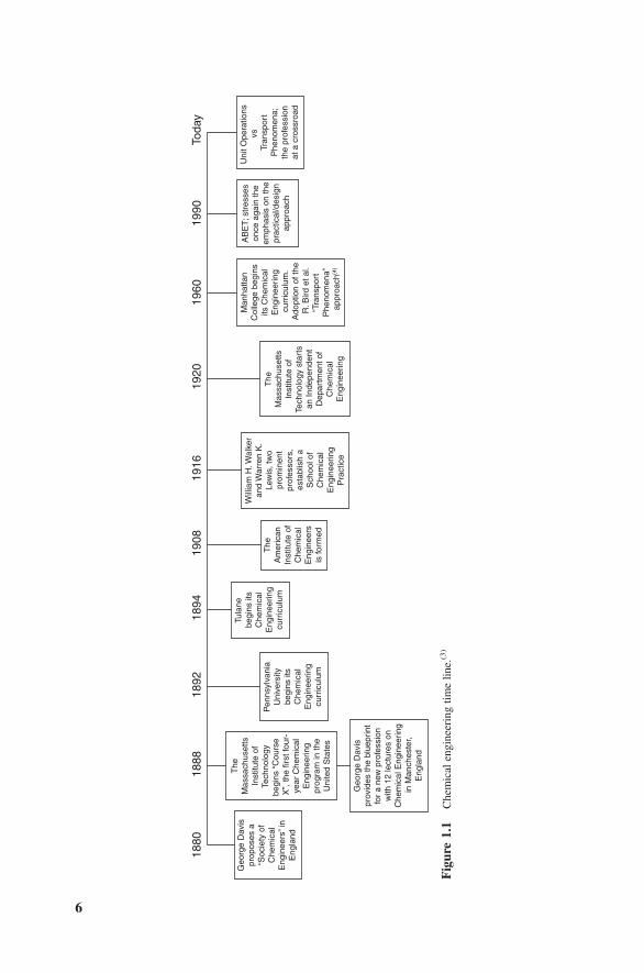
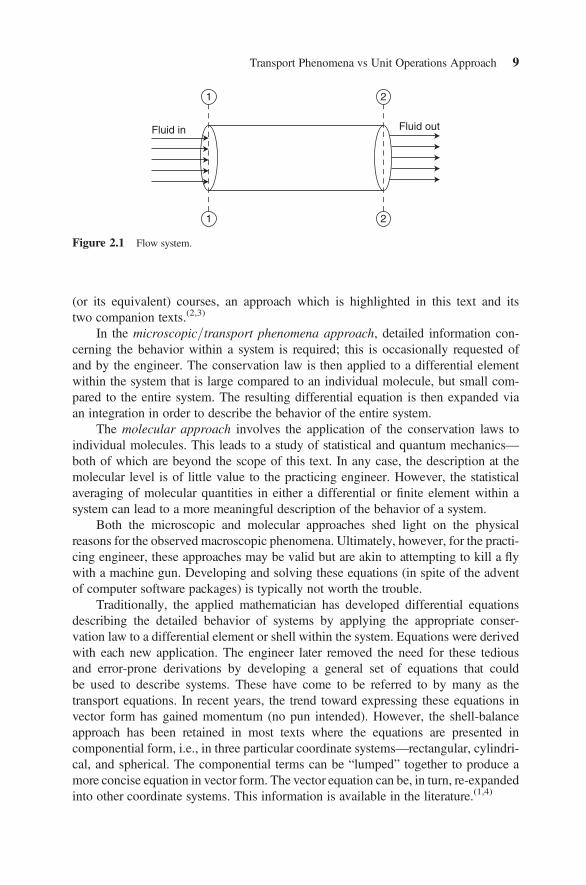
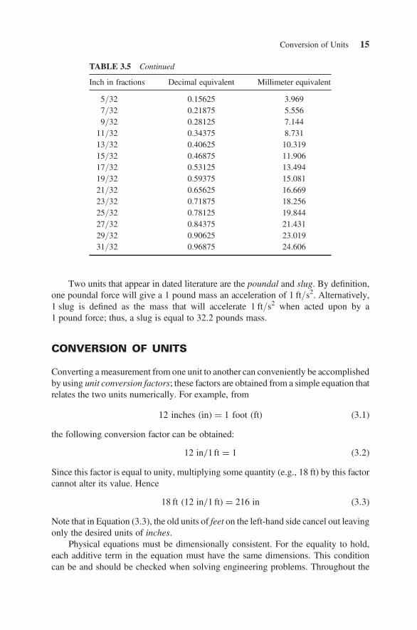
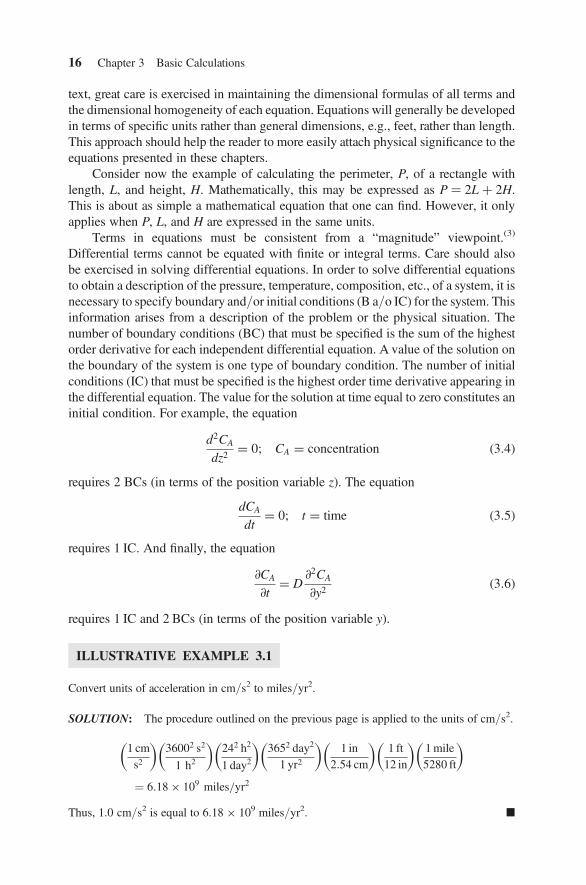
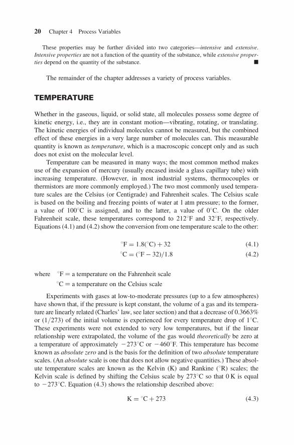
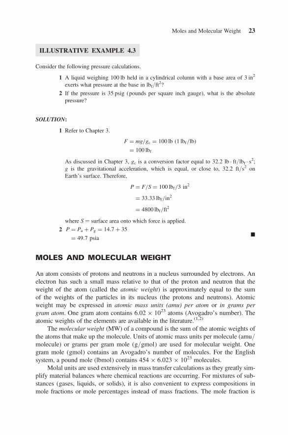
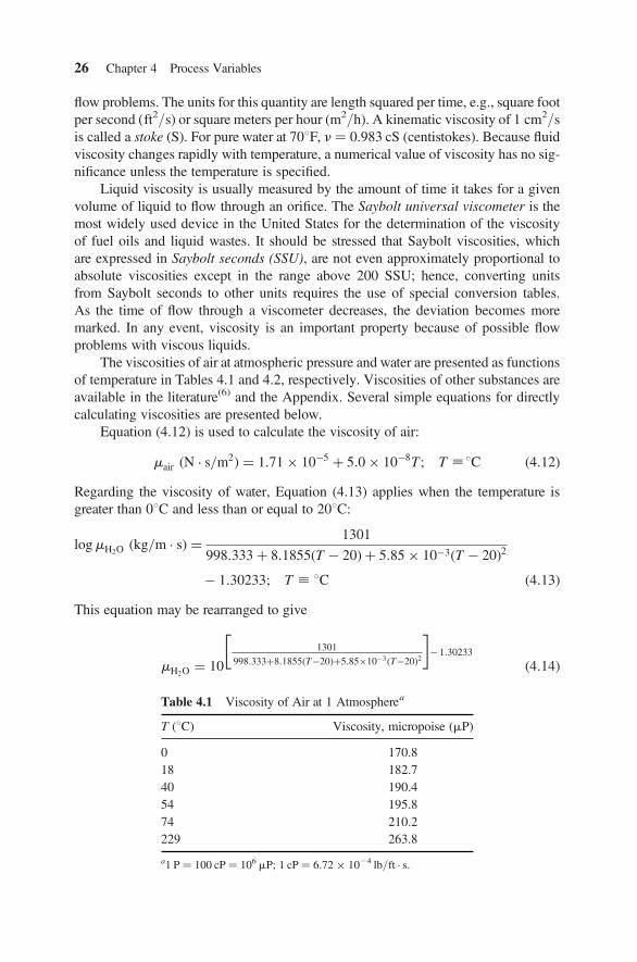
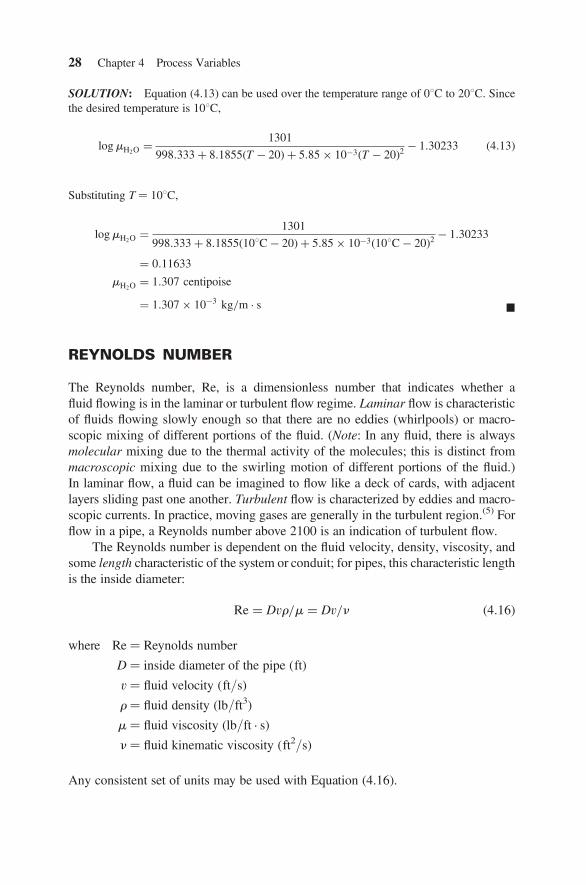
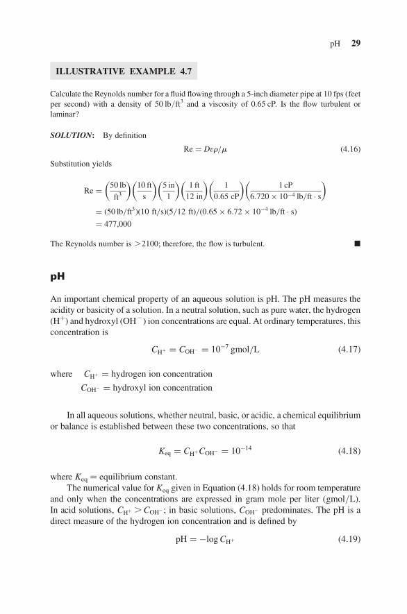
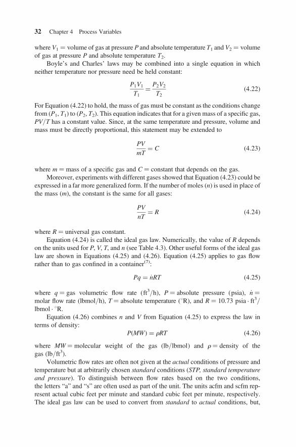
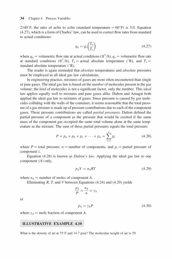
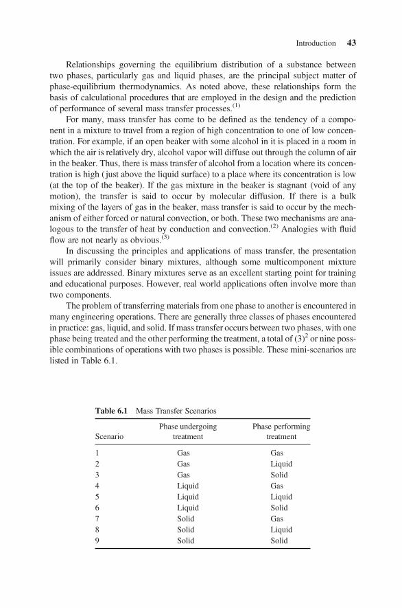