MASS TRANSFER COEFFICIENTS DURING AERATION BY …mixing14.eu/p/mixing14eu_38.pdf · 14th European...
6
14 th European Conference on Mixing Warszawa, 10-13 September 2012 MASS TRANSFER COEFFICIENTS DURING AERATION BY A SELF-ASPIRATING IMPELLER Czesław Kuncewicz , Jacek Stelmach Lodz University of Technology, Department of Process Equipment ul. Wólczańska 213, 90-924 Łódź, Poland [email protected] Abstract. Local values of mass transfer coefficient k L were determined for three types of self- aspirating impellers (disk, four- and six-pipe). Measurements were taken in 34 points on the plane between baffles in the tank at four rotation frequencies N = 365, 400, 450 and 500 min -1 . It was found that results obtained at the smallest frequency of rotations of a disk impeller were compatible with these attained basing on Whitman’s theory of laminar boundary layer. In the tested range of rotation frequencies the highest values of k L were achieved by a six-pipe impeller. Dependence of mean values of the mass transfer coefficient on rotation frequency of the impeller was also investigated and described by power equations. In the case of pipe impellers the exponent value was about 0.5, while for the disk impeller it was higher, i.e. around 0.8. A relation between the energy dissipation rate and distribution of mass transfer coefficients in the tank equipped with a disk impeller was also found. Keywords: self-aspirating impellers, mass transfer coefficient 1. INTRODUCTION In mass transfer processes an important parameter which has an effect on the transport rate is mass transfer coefficient. In the case of gases which are hardly soluble in liquids, the value of this coefficient is determined by the coefficient of mass transfer in the liquid phase k L . On the other hand, the value of k L depends primarily on hydrodynamic conditions in the system. Its direct specification is difficult, so most often it is determined via volumetric mass transfer coefficient k L a. However, the value of k L a depends on the unit interfacial area which significantly distorts the information on mass transfer conditions and a possibility to improve them in order to intensify the entire process. Therefore, from the distribution of k L in the whole tank much more information can be reached than from a similar distribution of k L a values. One of the ways to determine difficult-to-measure parameter k L is the electrochemical method [1,2]. Investigations carried out with this method are based on the use of a relation between the intensity of diffusion current flowing between electrodes in the model electrolyte and mass transfer coefficient in the tank. During transport of the substance and charges in the electrolyte stream, ions are transferred from the solution bulk to the electrode surface and current flowing between the electrodes according to Faraday’s law is equal to the flow of electroactive substance. A reason for migration of electric charges is the gradient of electric potential. During steady and one-direction mass transport, when redox reaction occurs in the solution and the reduction-oxidation system contains additionally both oxidized and reduced forms of a substance, we have pure flow of the bulk towards the electrode. In such conditions 241
Transcript of MASS TRANSFER COEFFICIENTS DURING AERATION BY …mixing14.eu/p/mixing14eu_38.pdf · 14th European...

14th European Conference on Mixing Warszawa, 10-13 September 2012
MASS TRANSFER COEFFICIENTS DURING AERATION BY A SELF-ASPIRATING IMPELLER
Czesław Kuncewicz, Jacek Stelmach
Lodz University of Technology, Department of Process Equipment
ul. Wólczańska 213, 90-924 Łódź, Poland
Abstract. Local values of mass transfer coefficient kL were determined for three types of self-aspirating impellers (disk, four- and six-pipe). Measurements were taken in 34 points on the plane between baffles in the tank at four rotation frequencies N = 365, 400, 450 and 500 min-1. It was found that results obtained at the smallest frequency of rotations of a disk impeller were compatible with these attained basing on Whitman’s theory of laminar boundary layer. In the tested range of rotation frequencies the highest values of kL were achieved by a six-pipe impeller. Dependence of mean values of the mass transfer coefficient on rotation frequency of the impeller was also investigated and described by power equations. In the case of pipe impellers the exponent value was about 0.5, while for the disk impeller it was higher, i.e. around 0.8. A relation between the energy dissipation rate and distribution of mass transfer coefficients in the tank equipped with a disk impeller was also found. Keywords: self-aspirating impellers, mass transfer coefficient
1. INTRODUCTION In mass transfer processes an important parameter which has an effect on the transport
rate is mass transfer coefficient. In the case of gases which are hardly soluble in liquids, the value of this coefficient is determined by the coefficient of mass transfer in the liquid phase kL. On the other hand, the value of kL depends primarily on hydrodynamic conditions in the system. Its direct specification is difficult, so most often it is determined via volumetric mass transfer coefficient kLa. However, the value of kLa depends on the unit interfacial area which significantly distorts the information on mass transfer conditions and a possibility to improve them in order to intensify the entire process. Therefore, from the distribution of kL in the whole tank much more information can be reached than from a similar distribution of kLa values.
One of the ways to determine difficult-to-measure parameter kL is the electrochemical method [1,2]. Investigations carried out with this method are based on the use of a relation between the intensity of diffusion current flowing between electrodes in the model electrolyte and mass transfer coefficient in the tank. During transport of the substance and charges in the electrolyte stream, ions are transferred from the solution bulk to the electrode surface and current flowing between the electrodes according to Faraday’s law is equal to the flow of electroactive substance. A reason for migration of electric charges is the gradient of electric potential.
During steady and one-direction mass transport, when redox reaction occurs in the solution and the reduction-oxidation system contains additionally both oxidized and reduced forms of a substance, we have pure flow of the bulk towards the electrode. In such conditions
241

the process is controlled only by the diffusion of ions to the electrode surface, i.e. according to Fick’s first law. When the number of diffusing ions does not balance a decreased number of ions being discharged on the electrode, there is concentration polarization. This is a criterion of deviation of the electrode potential from its equilibrium value. When the current reaches the value of diffusion current, the concentration of ions near the electrode surface tends to 0 ( 0* =AC ) and the equation which determines the mass transfer coefficient assumes the form · · ·⁄ (1) where: Id – diffusion current, cA – concentration of the reacting ion in the liquid bulk, ze –number of exchanged electrons, F – Faraday constant, S – electrode surface.
The major aim of this work is to determine local mass transfer coefficients in the tank with different types of self-aspirating impellers using the electrochemical method and to compare them with the values obtained on the basis of various mass transport theories. The next goal is to identify mean values and find their dependence on turbulence in the tank.
2. EXPERIMENTAL Experiments were carried out in a glass flat-bottom tank of diameter T = 292 mm.
equipped with four standard baffles (B = 0.1·T). Three self-aspirating impellers were used: disk (DI), four- (4PI) and six-pipe (6PI). The diameter of all impellers was D = 125 mm. Rotation frequencies of the impellers were the same, i.e. N = 365, 400, 450 and 500 min-1.
Fig. 1. Schematic of the measuring set-up with the grid of measuring points and impellers
Local values of coefficient kL were measured in the radial-axial plane determined by the
tank axis and angle bisector which includes two neighboring baffles. In this way the measuring plane was located at equal distances between the baffles. The anode was a platinum plate 2 cm × 3 cm placed on the tank bottom. The measuring cathode of diameter de = 4 mm was located in a specific point of the tank (Fig. 1). The intensity of current flowing in such a system was recorded by a digital meter and next transmitted to a computer at the frequency of 2 Hz. The intensity of diffusion current was calculated basing on a mean value from 100 measurements.
In the measuring system a cathode reduction of K3Fe(CN)6 on the platinum electrode surface was applied. The electrolyte used in the experiments was a water solution of K3Fe(CN)6 at the concentration 0.01 kmol/m3, K4Fe(CN)6 at the concentration 0.05 kmol/m3 and NaOH at the concentration 0.1 kmol/m3 (it played the role of a current carrier). In such a system the reactions of reduction-oxidation of iron ions took place.
242

Based on the preliminary measurements without gas dispersion, the tension of plateau was determined (U = 0.7 V) for which diffusion current was measured at working rotation frequencies of the impeller with gas dispersion. For the recorded values of diffusion current Id the mass transfer coefficient kL was calculated from equation (3).
3. RESULTS AND DISCUSSION Basing on the obtained data, contour plots of kL distribution on the tested tank cross
section were prepared. Figure 2 shows the distribution of local mass transfer coefficients kL at the impeller rotation frequency N = 365 min-1. At this rotation frequency of the impellers the stream of dispersed gas is small and has no significant effect on liquid hydrodynamics in the tank [3]. Therefore, for this frequency of impeller rotations it is possible to verify results obtained with the values calculated by means of various mass transport theories.
Fig. 2. Distributions of kL for N = 365 min-1
The highest values of kL appear on the level of the impeller suspension at the distance of
several millimeters from the blade tips. Experiments carried out for impeller DI rotating at the frequency N = 360 min-1 showed [3] that in this region the highest relative velocities of liquid and bubbles occurred (Fig. 3a) which should ensure the best mass transport conditions. From Whitman’s theory of laminar boundary layer the following relation was obtained [4,5]
· · ⁄ · ⁄ (2)
where d – bubble diameter, DA – diffusion coefficient, vs – bubble velocity vs. liquid, c – constant (c = 0.42 ÷ 0.95). It is assumed that bubble diameter is the Sauter diameter which for gas dispersed by impeller DI in the electrolytes can be calculated from the relation [6]:
· · 0,28 · , ·,·
, (3)
In the discussed conditions it is d32 = 0.66 mm. On the basis of literature data the value of diffusion coefficient can be assumed as equal to DAB = 1.5·10-9 m2/s [7].
Higbie’s penetration model leads to the relation [4,5,8]:
1,13 · · / (4)
According to literature data, the experimentally determined values of kL are within the range of values calculated from relations (2) and (4). Figure 3b shows a comparison of experimental kL values and these calculated from equation (2) for c = 0.42 and from equation (4) for the height equal to the height of the impeller suspension. Good agreement was obtained with the model of laminar boundary layer. Values calculated from equation (4) are by one order of magnitude bigger than these determined experimentally. This confirms information given in the literature that relation (2) is applied to small bubbles of diameters smaller than 1 mm [5].
1
2
3
4
5
46
0 20 40 60 80 100 120 1400
50
100
150
200
250
x [mm]
y[m
m]
1
2
3
45
2
7
4
0 20 40 60 80 100 120 140
x [mm]
1
2
45
678
4 4
0 20 40 60 80 100 120 140
x [mm]
0 1 2 3 4 5 6 7 8
kL·105 [m/s]
DI 4PI 6PI
243
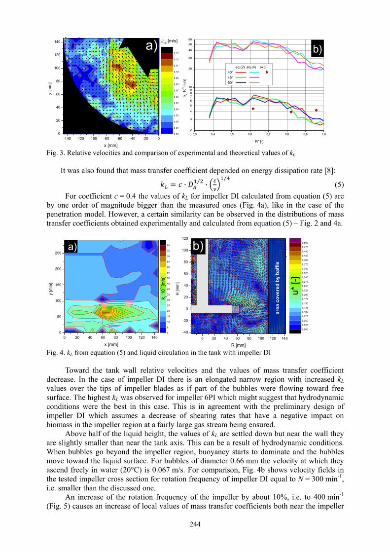
Fig. 3. Relative velocities and comparison of experimental and theoretical values of kL
It was also found that mass transfer coefficient depended on energy dissipation rate [8]:
· ⁄ ·⁄
(5) For coefficient c = 0.4 the values of kL for impeller DI calculated from equation (5) are
by one order of magnitude bigger than the measured ones (Fig. 4a), like in the case of the penetration model. However, a certain similarity can be observed in the distributions of mass transfer coefficients obtained experimentally and calculated from equation (5) – Fig. 2 and 4a.
Fig. 4. kL from equation (5) and liquid circulation in the tank with impeller DI
Toward the tank wall relative velocities and the values of mass transfer coefficient
decrease. In the case of impeller DI there is an elongated narrow region with increased kL values over the tips of impeller blades as if part of the bubbles were flowing toward free surface. The highest kL was observed for impeller 6PI which might suggest that hydrodynamic conditions were the best in this case. This is in agreement with the preliminary design of impeller DI which assumes a decrease of shearing rates that have a negative impact on biomass in the impeller region at a fairly large gas stream being ensured.
Above half of the liquid height, the values of kL are settled down but near the wall they are slightly smaller than near the tank axis. This can be a result of hydrodynamic conditions. When bubbles go beyond the impeller region, buoyancy starts to dominate and the bubbles move toward the liquid surface. For bubbles of diameter 0.66 mm the velocity at which they ascend freely in water (20°C) is 0.067 m/s. For comparison, Fig. 4b shows velocity fields in the tested impeller cross section for rotation frequency of impeller DI equal to N = 300 min-1, i.e. smaller than the discussed one.
An increase of the rotation frequency of the impeller by about 10%, i.e. to 400 min-1 (Fig. 5) causes an increase of local values of mass transfer coefficients both near the impeller
-140 -120 -100 -80 -60 -40 -20 00
20
40
60
80
100
120
140
x [mm]
y[m
m]
0,00
0,01
0,02
0,03
0,04
0,05
0,06
0,07
0,08
0,09
0,10
0,11
0,12
0,13
Urel [m/s]a)
0,3 0,4 0,5 0,6 0,7 0,8 0,9 1,02
3
4
56789
10
20
30
40
5060
k L·105 [m
/s]
R* [-]
eq.(2) eq.(4) exp.40° 45° 50°
b)
0 20 40 60 80 100 120 1400
50
100
150
200
250
x [mm]
y [m
m]
0
5
10
15
20
25
30
35
40
45
50
55
60
65
70
75
80
k L·105 [m
/s]
a)
0 20 40 60 80 100 120 140-40
-20
0
20
40
60
80
100
120
R [mm]
H[m
m]
0,000
0,025
0,050
0,075
0,100
0,125
0,150
0,175
0,200
0,225
0,250
0,275
0,300
0,325
0,350
0,375
0,400
0,425
0,450
0,475
0,500
area
cov
ered
by
baffl
e
b)
u* [-
]
244

and in other parts of the tank. Any further increase of the rotation frequency of the impeller (Fig. 6 and 7) does not affect so strongly the values of kL near the impeller. Enlarged are the regions with higher kL values in the remaining part of the tank.
Fig. 5. kL distributions at N = 400 min-1
Fig. 6. kL distributions at N = 450 min-1
Fig. 7. kL distributions at N = 500 min-1
The use of weighted average with weights equal to volume fractions for which the value
of <kL> was determined, allows us to calculate mass transfer coefficient for the entire tank. Figure 8 shows values obtained depending on the impeller rotation frequency. Figure 8 presents also dimensional correlation equations in which global/mean mass transfer coefficient <kL> [m/s] depends on rotation frequency of the impeller N [s-1]. Since the Reynolds number is proportional to the impeller rotation frequency, it was decided to use a power relation which was typical of correlation equations describing mass transfer. Exponents in the equations for pipe impellers (4PI and 6PI) have almost identical values close to 0.5.
1
2
3
4
56
7
0 20 40 60 80 100 120 1400
50
100
150
200
250
x [mm]
y[m
m]
1
2
3
45
74
0 20 40 60 80 100 120 140
x [mm]
12
3
45
6
3
78
4
95
0 20 40 60 80 100 120 140
x [mm]
0 1 2 3 4 5 6 7 8 9 10
kL·105 [m/s]
DI 4PI 6PI
1
3
4
3
56
7
4
0 20 40 60 80 100 120 1400
50
100
150
200
250
x [mm]
y[m
m]
12
3
4
456
7
0 20 40 60 80 100 120 140
x [mm]
12
3
4
5
5
3
6
78910 7
3
6
6
0 20 40 60 80 100 120 140
x [mm]
0 1 2 3 4 5 6 7 8 9 10 11 12
kL·105 [m/s]
DI 4PI 6PI
1
3
4
56
7
0 20 40 60 80 100 120 1400
50
100
150
200
250
x [mm]
y[m
m]
12
4
56
7
0 20 40 60 80 100 120 140
x [mm]
12
3
4
5
5
77910
6
0 20 40 60 80 100 120 140
x [mm]
0 1 2 3 4 5 6 7 8 9 10 11 12
kL·105 [m/s]
DI 4PI 6PI
245
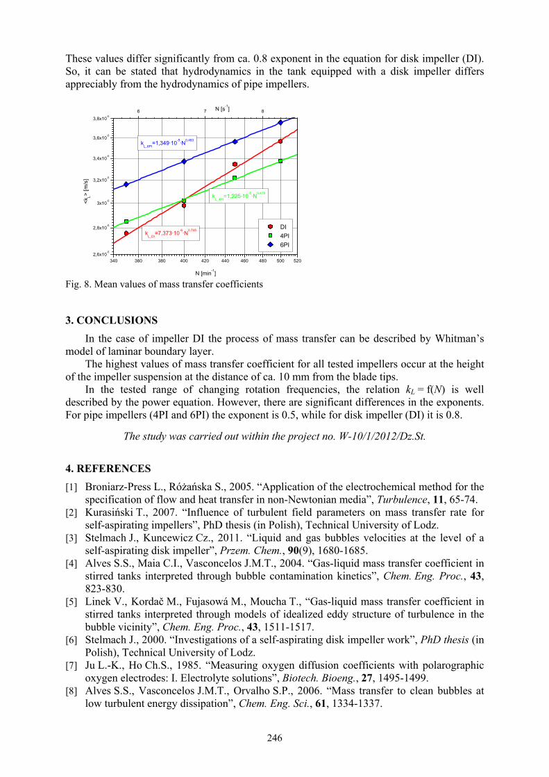
These values differ significantly from ca. 0.8 exponent in the equation for disk impeller (DI). So, it can be stated that hydrodynamics in the tank equipped with a disk impeller differs appreciably from the hydrodynamics of pipe impellers.
Fig. 8. Mean values of mass transfer coefficients
3. CONCLUSIONS
In the case of impeller DI the process of mass transfer can be described by Whitman’s model of laminar boundary layer.
The highest values of mass transfer coefficient for all tested impellers occur at the height of the impeller suspension at the distance of ca. 10 mm from the blade tips.
In the tested range of changing rotation frequencies, the relation kL = f(N) is well described by the power equation. However, there are significant differences in the exponents. For pipe impellers (4PI and 6PI) the exponent is 0.5, while for disk impeller (DI) it is 0.8.
The study was carried out within the project no. W-10/1/2012/Dz.St.
4. REFERENCES [1] Broniarz-Press L., Różańska S., 2005. “Application of the electrochemical method for the
specification of flow and heat transfer in non-Newtonian media”, Turbulence, 11, 65-74. [2] Kurasiński T., 2007. “Influence of turbulent field parameters on mass transfer rate for
self-aspirating impellers”, PhD thesis (in Polish), Technical University of Lodz. [3] Stelmach J., Kuncewicz Cz., 2011. “Liquid and gas bubbles velocities at the level of a
self-aspirating disk impeller”, Przem. Chem., 90(9), 1680-1685. [4] Alves S.S., Maia C.I., Vasconcelos J.M.T., 2004. “Gas-liquid mass transfer coefficient in
stirred tanks interpreted through bubble contamination kinetics”, Chem. Eng. Proc., 43, 823-830.
[5] Linek V., Kordač M., Fujasowá M., Moucha T., “Gas-liquid mass transfer coefficient in stirred tanks interpreted through models of idealized eddy structure of turbulence in the bubble vicinity”, Chem. Eng. Proc., 43, 1511-1517.
[6] Stelmach J., 2000. “Investigations of a self-aspirating disk impeller work”, PhD thesis (in Polish), Technical University of Lodz.
[7] Ju L.-K., Ho Ch.S., 1985. “Measuring oxygen diffusion coefficients with polarographic oxygen electrodes: I. Electrolyte solutions”, Biotech. Bioeng., 27, 1495-1499.
[8] Alves S.S., Vasconcelos J.M.T., Orvalho S.P., 2006. “Mass transfer to clean bubbles at low turbulent energy dissipation”, Chem. Eng. Sci., 61, 1334-1337.
340 360 380 400 420 440 460 480 500 5202,6x10-5
2,8x10⁻⁵
3x10⁻⁵
3,2x10⁻⁵
3,4x10⁻⁵
3,6x10⁻⁵
3,8x10⁻⁵
DI 4PI 6PI
<kL>
[m/s
]
N [min-1]
6 7 8
kL_6PI
=1,349·10-5·N0,483
kL_4PI
=1,225·10-5·N0,478
N [s-1]
kL_DI
=7,373·10-6·N0,745
246