Mass Interconnect and Fixturing - National...
12
ni.com/automatedtest CONTENTS Introduction Overview of a Mass Interconnect System How to Choose a Mass Interconnect System Overview of a Test Fixture Fixture Considerations Next Steps FUNDAMENTALS OF BUILDING A TEST SYSTEM Mass Interconnect and Fixturing
-
Upload
hoangkhanh -
Category
Documents
-
view
218 -
download
0
Transcript of Mass Interconnect and Fixturing - National...

ni.com/automatedtest
CONTENTS
Introduction
Overview of a Mass Interconnect System
How to Choose a Mass Interconnect System
Overview of a Test Fixture
Fixture Considerations
Next Steps
FuNdaMENTalS OF BuIldINg a TEST SySTEM
Mass Interconnect and Fixturing

ni.com/automatedtest
Mass Interconnect and Fixturing2
IntroductionBuilding a test system without a plan for how you will connect your instrumentation to your device under test (duT) is similar to trying to drive your car without wheels. your car may have best-in-class horsepower and Italian leather seats, but you aren’t going to reach your destination without wheels. Mass interconnects and test fixtures are where the rubber meets the road for automated test systems. after determining your instrumentation, the number of switches you need, and the location that your switches will reside in the test system, the next step is to choose a suitable mass interconnect system and design an appropriate fixture that seamlessly mates your duTs to the rest of the system.
Overview of a Mass Interconnect System a mass interconnect system is a mechanical interconnect designed to easily facilitate the connection of a large number of signals either coming from or going to a duT or duT fixture. Rather than connect each signal one by one, a mass interconnect system connects and disconnects all signals at once. For automated test systems, a mass interconnect system usually entails some interchangeable mechanical enclosure through which all signals are routed from instruments, typically in a test rack, to the duT, making it easy to quickly change duTs or to protect the cable connections on the front of the instruments from repeated connect and disconnect cycles.
Figure 1. a mass interconnect system simultaneously connects a large number of signals between your test system and duT, providing an easy way to reuse common test equipment with multiple test fixtures for different duTs.

ni.com/automatedtest
Mass Interconnect and Fixturing3
RECEIvER
System-Side ComponentsThe system-side components comprise everything between the instrumentation and the mass interconnect. System-side components are part of the common components that stay with the test system, even if you change the interchangeable test adapter (ITa) and fixture to interface with various duTs. Below is a brief explanation of each of the system-side components.
ReceiverThe receiver is the core component of the test system side of the mass interconnect. It is the mechanism that provides the ability to connect multiple instruments simultaneously to the duT. The receiver system includes the frame, mounting hardware, receiver modules, and the connections from receiver modules to instrumentation.
Mounting HardwareMounting hardware holds the receiver on the front of the rack or PXI chassis. It is typically mounted on the front side of a 19-inch rack, providing easy access for the test operator. Sometimes, the mounting hardware has a hinge, or is mounted on slides, for easy access to the instruments or cables behind the receiver.
Receiver Modules Receiver modules are mounted into the receiver so that all appropriate connections can be made from instrumentation to the receiver’s main connector, a type of standard connector that is connected to the duT side of the mass interconnect system, along with all other receiver modules, in one mechanical action. The connections are routed from the instruments and other auxiliary equipment to the appropriate contacts within the receiver modules. These are typically specified according to density, bandwidth, current, or other special-purpose requirement of the signals being passed through them.
Figure 2. a mass interconnect system can be simplified into two parts. The system-side components, often referred to as the receiver, connect instrumentation to the mass interconnect, acting as the “socket” for the ITa. alternatively, the duT-side components, often referred to as the ITa, connect the duT to the mass interconnect, acting as the “plug” for the receiver. The receiver and ITa mate together with a single mechanical action, providing an easy way to reuse a common set of test hardware with various duTs.
PXI SySTEM
Receiver Module 1
Receiver Module 2
Receiver Module 3
Receiver Module 4
PXI Oscilloscope
PXI Source Measure unit
PXI vector Signal Transceiver
PXI digital I/O
INTERCHaNgEaBlE TEST adaPTER (ITa)
ITa Module 1
ITa Module 2
ITa Module 3
ITa Module 4
TESTFIXTuRE
ORCaBlE
duT(s)
SySTEM SIdE duT SIdE

ni.com/automatedtest
Mass Interconnect and Fixturing4
To connect instruments and other auxiliary equipment to the receiver modules, two methods can be used independently or in combination:
■■ Cable Assemblies—With cable assemblies, standard or custom-made cables are connected from the instruments directly to contacts in the receiver. Cable assemblies offer more flexibility with mounting and receiver module location, but typically have longer signal paths (24 in. or more) between the receiver module and instrument, which can affect performance if not managed correctly.
■■ Interface Adapters—Interface adapters typically connect all I/O from the instrument connectors (for example, dIN, d-SuB, SCSI, and so on) to the receiver modules. The adapters are always directly in line with the instrument and use printed circuit boards (PCBs), flex circuits, or cables to provide the most efficient connection method for the particular instrument. Interface adapters offer the advantage of minimizing the signal length (usually 6 in.) and variable signal performance between the receiver module and the instrument, but are rigid and therefore require more upfront planning and precise, inflexible mounting locations.
Figure 3. Cable assemblies (top) offer flexibility with mounting and receiver module location but typically have longer signal paths. PCBs (middle) and flex circuits (bottom) minimize signal length, preserving signal quality but offering less flexiblity than cable assemblies.
Table 1. Cables are useful for designing and characterizing a device, but a mass interconnect is ideal for a production test environment.
CablesMass Interconnect
With CablesMass Interconnect With
PCBs or Flex Circuits
Frequent Changeover Between duTs ○ ● ●Optimized for design and Characterization ● ○ ○Optimized for verification and validation (v&v) ◒ ◒ ◒Optimized for Test Production ○ ● ●Signal Quality ◒ ◒ ●Continuity of Performance (System to System) ◒ ◒ ●Ease of System Maintenance and upgradability ○ ● ●System Reconfiguration (that is, Scalability) ○ ● ●Ease of duplication (for example, global deployments) ○ ◒ ●Instrument to Module Pin Efficiency ○ ● ◒Repairability in the Field ● ● ○Instrument Card Rev. Control Tolerance ● ● ○
Below ○ average ◒ above ●
Flex Circuit
PCB
Cable

ni.com/automatedtest
Mass Interconnect and Fixturing5
DUT-Side ComponentsThe duT-side components comprise everything between the mass interconnect and the fixture or duT. duT-side components are assembled as one unit, often referred to as the ITa, and can be easily interchanged to test different duTs with a common set of instrumentation. Below is a brief explanation of each of the duT-side components.
ITAThe interchangeable test adapter (ITa) is the core component of the duT side of the mass interconnect, encompassing the enclosure, or mechanical frame, that contains the ITa modules and contacts that mate with the receiver and transfers the system inputs and outputs to the duT. If the receiver is the socket, the ITa is the plug. Many test systems are designed to test many different duTs by interchanging different ITas while using the same test system and receiver.
ITA ModulesThe ITa modules are mounted inside the ITa in much the same way that the receiver modules are mounted inside the receiver. They provide the main interconnect with the various signals routed through the receiver and expose those connections through cables, PCBs, or other connections inside the ITa enclosure. The ITa modules and contacts are chosen to match the receiver modules and contacts previously specified. The appropriate signals are then routed within the enclosure to the fixture or duT connectors.
EnclosureThe enclosure is the mechanical housing around the ITa and corresponding ITa cables/modules. It is common to integrate the ITa enclosure and test fixture into a single frame or physical platform on which to set the duT, as in consumer electronic or semiconductor testing, or have a single cable connected between the ITa and the duT. although you can choose from standard enclosures, in practice almost every enclosure is customized in some manner to suit the requirements of the duT.
Test FixtureEach duT is different and requires a unique method of connection to achieve the most efficient testing. For example, some duTs benefit from a single cable between the ITa and duT, whereas others benefit most from an integrated test fixture, such as a bed of nails fixture, providing a direct connection method without cables.
ni.com/automatedtest
Mass Interconnect and Fixturing6
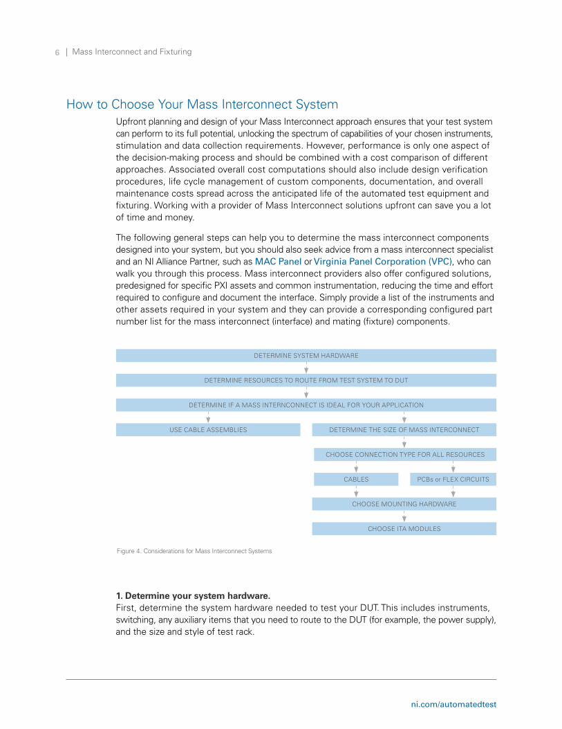
How to Choose your Mass Interconnect Systemupfront planning and design of your Mass Interconnect approach ensures that your test system can perform to its full potential, unlocking the spectrum of capabilities of your chosen instruments, stimulation and data collection requirements. However, performance is only one aspect of the decision-making process and should be combined with a cost comparison of different approaches. associated overall cost computations should also include design verification procedures, life cycle management of custom components, documentation, and overall maintenance costs spread across the anticipated life of the automated test equipment and fixturing. Working with a provider of Mass Interconnect solutions upfront can save you a lot of time and money.
The following general steps can help you to determine the mass interconnect components designed into your system, but you should also seek advice from a mass interconnect specialist and an NI alliance Partner, such as MAC Panel or Virginia Panel Corporation (VPC), who can walk you through this process. Mass interconnect providers also offer configured solutions, predesigned for specific PXI assets and common instrumentation, reducing the time and effort required to configure and document the interface. Simply provide a list of the instruments and other assets required in your system and they can provide a corresponding configured part number list for the mass interconnect (interface) and mating (fixture) components.
1. Determine your system hardware. First, determine the system hardware needed to test your duT. This includes instruments, switching, any auxiliary items that you need to route to the duT (for example, the power supply), and the size and style of test rack.
Figure 4. Considerations for Mass Interconnect Systems
dETERMINE SySTEM HaRdWaRE
dETERMINE RESOuRCES TO ROuTE FROM TEST SySTEM TO duT
dETERMINE IF a MaSS INTERNCONNECT IS IdEal FOR yOuR aPPlICaTION
uSE CaBlE aSSEMBlIES dETERMINE THE SIzE OF MaSS INTERCONNECT
CHOOSE CONNECTION TyPE FOR all RESOuRCES
CaBlES PCBs or FlEX CIRCuITS
CHOOSE MOuNTINg HaRdWaRE
CHOOSE ITa MOdulES

ni.com/automatedtest
Mass Interconnect and Fixturing7
2. Determine which resources from the test system need routing to the DUT. depending on the complexity of the test system and the device being tested, you will most likely route all required instrument and auxiliary component connections through the mass interconnect system. Some test components do not need to be routed through the mass interconnect, such as PXI embedded controllers or RaId storage systems.
When choosing the resources that you plan to route through the mass interconnect, consider how your test requirements might change in the future so you can build a flexible test system that can meet future requirements. For example, if you have extra resources, such as extra instrument or power supply channels, that you do not need for your current generation of duTs but think you might need for future duT generations, then you can save time and money by routing those resources in anticipation of future changes.
3. Decide the best style of interface for the application—cables or a mass interconnect. This choice depends on a number of factors, including the complexity of the system, technical performance requirements, flexibility, and total cost of ownership. use Table 1 as a guide for your decision, but seek advice from a mass interconnect specialist to ensure you make the correct choice for your particular test system. assuming that you decide to use a mass interconnect, the following steps can help you determine the size of receiver and ITa and select receiver modules, ITa modules, and mounting hardware.
4. Determine the size of the receiver and ITA. you can choose from many different receiver sizes and styles, depending on the answers to the previous questions. Consider reserving spare slots in the receiver for future expansion. Similar to planning instrumentation for a PXI system, a general guideline is that a minimum of 20 percent of the slots should be unpopulated in an initial design. Note that the ITa size will always match the receiver size.
5. Choose receiver modules and a connection method (cables or interface adapters) to accommodate routing of all necessary resources. your choice of receiver modules and connections depends on your test goals and the chosen instruments and any other auxiliary requirements. again, you can use Table 1 as a guide for your decision, but seek advice from a mass interconnect specialist to ensure you make the correct choice for your particular test system. you can choose from a wide range of contact styles and predesigned interface adapters, patch cords, or predesigned cables to meet the requirements of any signal type, including:
■■ low-frequency aC signals ■■ Power■■ RF signals■■ Microwave signals■■ Thermocouple■■ Fiber optics■■ Pneumatic■■ High-speed signals and data transmission

ni.com/automatedtest
Mass Interconnect and Fixturing8
6. Choose mounting hardware. after selecting your receiver modules and connection method, the next step is to choose the mounting hardware, which depends on several factors. Most systems using a mass interconnect will mount to a 19 in. rack assembly. With a cabled system, it is often advantageous to mount the receiver on a hinged frame, or on slides, to allow access to the instruments and chassis. If using interface adapters, the receiver is mounted to the PXI chassis using standard mounting flanges and the receiver and chassis are then mounted onto a slide shelf within the rack.
7. Choose mating ITA modules and contacts. Configure the ITa modules and contacts to match your choices from step five. It may not be necessary to fully populate contacts in the ITa modules to completely match the contacts in the receiver modules. In most cases, all the resources from a particular instrument will be passed to the receiver module. However, not all of these resources are required on the ITa side to test a particular duT; therefore, not all ITa modules need to be fully populated with contacts.
Overview of a Test Fixturea test fixture is a device that provides repeatable connectivity between your test system and your duT, and it is often custom designed to meet the needs of a specific duT. using a mass interconnect at the fixture back side, you can interchange various test fixtures with a common rack of instruments; you can reuse the test equipment by easily interchanging the test fixtures for different duTs, which is ideal for a universal tester or high-mix tester.
When designing a test fixture, know in advance what types of tests you plan to perform, because the needs for device design, duT characterization, verification and validation (v&v), and production testing are quite different and require different features from a test fixture.
Figure 5. Production test systems require rugged, streamlined test fixtures that you can easily duplicate, whereas design and characterization instrument systems require the flexibility that cables, probes, and Kelvin clips provide.
duPlICaBlE, RuggEd, aNd STREaMlINEd
FlE
XIB
lE
Design and Characterization
Verification and Vaildation
Production Test

ni.com/automatedtest
Mass Interconnect and Fixturing9
Design and Characterizationduring a product’s design phase, you must have the flexibility to easily connect and disconnect one or more cables or pins from the duT to the measurement instrumentation to test or troubleshoot any and all elements of the design. For this reason, you need a highly flexible way of interfacing with instrumentation rather than a streamlined or rugged test system with mass interconnect and fixture. Many design engineers use instrumentation with cables, probes, and Kelvin clips, which provide a way to easily change connections. In addition to troubleshooting, design engineers often characterize, or describe, the actual behavior of a device, which contributes to device specifications and guides test engineers in developing a v&v station or production test system.
Verification and Validationv&v is the process of checking whether a specific product meets design specifications by testing a statistically representative set of the product.
Verificationverification is an objective process to check that a device meets the required regulations and specifications. you often perform verification during the design and development phase, as well as after the development phase is complete. during the development phase, verification testing sometimes simulates or models the behavior of the rest of the system to predict or preview how a device might behave when it is complete. after development is complete, verification testing can take the form of regression testing, repeating many tests designed to ensure that the device continues to meet the design requirements as time progresses.
Validationvalidation is a more subjective process, involving subjective assessments that a device meets the operational needs of the end user by returning to the problem statement that created the need for a new product. Requirements for validation testing can come from user requirements, specifications, and/or industry regulations. When validating specifications, the goal is to ensure that the specification captures user requirements, not ensuring that a given device meets its specifications.
The test data collected during the v&v process is also used to determine the test limits for the production test system. although only a small set of a given product undergoes v&v, almost all final products pass through production test. as a result, fixtures designed for v&v are often required to make fewer connections between the duT and instrumentation, allowing them to be less rugged than those used for production test.

ni.com/automatedtest
Mass Interconnect and Fixturing10
Production TestProduction, or functional, test is typically performed at the end of the manufacturing process and tests whether the product meets the published specifications and quality standards. Many times, functional tests are automated to optimize throughput and reduce errors from human interaction. Sometimes, production tests include the emulation or simulation of the environment in which the product will eventually operate. Most importantly, functional tests use the final connectors that a customer will eventually use rather than various test points directly on a PCB.
Because every device built and shipped undergoes production testing, you must design your fixture to be rugged to maximize uptime and be easy to use and ergonomic. you should also minimize the amount of interaction that the test operator must provide. Extra time spent aligning the duT to the fixture or connecting cables from instrumentation to the fixture negatively impacts throughput and increases test costs, as well as increases the likelihood of errors because of human interaction. Finally, production test systems, including a test fixture, should be easy to duplicate for additional deployments.
Fixture ConsiderationsWhen designing a test fixture, ensure that it uses proper wiring types and techniques, uses PCBs rather than cables when possible, and automates as many connections as feasible. also create a preventive maintenance plan for your test fixture to ensure a long and successful deployment.
Use Proper WiringWires are often sources of noise and error, so you should select the best type of wires for your test fixture. To ensure signal integrity, some wires offer features such as insulation, shielding, guarding, or twisted pairs. Some instrument manuals suggest using specific cables, but it often depends on the type of measurements being performed. For example, twisted pair cables are ideal for rejecting noise when performing differential measurements. using a shielded cable is also a technique for rejecting noise, but it is important to use the correct grounding scheme based on the grounding of your signal source and input configuration. Finally, guarding is often used to remove the effects of leakage currents and parasitic capacitances between the HI and lO terminals of a digital multimeter (dMM) or source measure unit (SMu).
Figure 6. To preserve signal integrity, different cables offer different features such as shielding, insulation, twisted pairs, or guarding.
Pair Shield
Outer Jacket
Insulation
Braided Wire Conductor
Twisted Pair
ni.com/automatedtest
Mass Interconnect and Fixturing11
Minimize Operator InteractionThe goal of a mass interconnect system is to increase test equipment reuse and reduce the amount of operator interaction that can cause errors, lower throughput, and increase the total cost of test. In addition to limiting user interaction with a mass interconnect system, a good test fixture should maximize the number of connections made between the test fixture and duT with a single interaction from the test operator. For example, some test fixtures complete multiple connections with a connection method that is either driven with a single operator handle, or automatically with an electric or pneumatic motor. For production test, the connections are typically made using the connector that a customer eventually uses to interface with the device.
Build a Scalable Fixture That Is Easy to DuplicateCertain wiring techniques can preserve signal integrity, but consider using PCBs within your test fixture to improve signal integrity performance and reduce the wiring burden on the test operator or technician during the setup phase. using a test fixture that makes many connections at once is good for throughput, test repeatability, and user ergonomics, but it is still important to reduce the amount of wiring within the test fixture and replace them with a PCB when possible, as this can further improve signal integrity and reduce the time required to set up and wire each duplicate test system. The trade-off is that designing a custom PCB requires more upfront cost and effort, but pays dividends during system setup for the first system and for each reproduced test system.
Create a Preventive Maintenance Plan for Your Test FixtureTo ensure long-term support for your test system, include test fixture maintenance plans in your overall test system maintenance plan. This should include inspection and/or replacement of connectors, cables, pogo pins, relays, and other components at regular intervals throughout the test system’s lifetime. When choosing inspection cadence, consider the failure rate of a given component. To judge failure rate, take into account the vendor-supplied mean time between failure (MTBF) or the in-service failure rate specific to your organization. although both are useful when comparing or analyzing instrumentation, the in-service failure rate can be more useful, because it is indicative of how an instrument is actually used for a particular application. In the case that in-service failure rate data is unavailable, you can derive a theoretical failure rate from the MTBF data to plan an inspection interval that aligns with your cost and risk tolerance.

ni.com/automatedtest
Mass Interconnect and Fixturing12
Next Steps
NI PXI AdvisorThe PXI advisor helps you compare instrument options and configure a PXI-based test system, including PXI chassis, controller, modules, software, services, and auxiliary items.
Configure your test system using our PXI Advisor
MAC PanelMaC Panel is a solution source for companies looking to achieve reliable, cost-effective, electrical connections in a test or measurement environment. In addition to a full line of mass interconnect products, featuring the MaC Panel SCOuT mass interconnect system designed for PXI, MaC Panel also provides custom wiring services, sheet metal fabrication, and custom design assistance, providing a range of options to support automated test equipment on a global scale.
learn more about MAC Panel
Virginia Panel Corporationvirginia Panel Corporation (vPC) is an ISO certified manufacturer of Mass InterConnect solutions. With over 150 employees, vPC is able to design and manufacture large or small I/O connectors and interfaces for the Test and Measurement industry. In addition to Mass InterConnect solutions for PXI platforms, vPC also provides several value-add services like high speed PCB design, pre-configured test solutions, custom design assistance, web access to product support files, and online configuration tools.
learn more about VPC
NI Alliance Partner DirectoryThe NI alliance Partner Network is a program of more than 1,000 independent, third-party companies worldwide that offer complete products, as well as integration, consulting, and training services. Some of these companies, such as MaC Panel and vPC, offer custom cabling solutions, mass interconnect systems, and complete fixturing solutions.
Browse the Alliance Partner Directory
©2016 National Instruments. all rights reserved. National Instruments, NI, and ni.com are trademarks of National Instruments. Other product and company names listed are trademarks or trade names of their respective companies. a National Instruments alliance Partner is a business entity independent from National Instruments and has no agency, partnership, or joint-venture relationship with National Instruments.