Chapter Four fluid flow mass, energy, Bernoulli and momentum

M A S S , B E R N O U L L I , A N D E N E R G Y E Q U AT I O N S
This chapter deals with three equations commonly used in fluid
mechanics: the mass, Bernoulli, and energy equations. The mass equa-
tion is an expression of the conservation of mass principle. The
Bernoulli equation is concerned with the conservation of kinetic, potential,
and flow energies of a fluid stream and their conversion to each other in
regions of flow where net viscous forces are negligible and where other
restrictive conditions apply. The energy equation is a statement of the con-
servation of energy principle. In fluid mechanics, it is found convenient to
separate mechanical energy from thermal energy and to consider the con-
version of mechanical energy to thermal energy as a result of frictional
effects as mechanical energy loss. Then the energy equation becomes the
mechanical energy balance.
We start this chapter with an overview of conservation principles and the
conservation of mass relation. This is followed by a discussion of various
forms of mechanical energy and the efficiency of mechanical work devices
such as pumps and turbines. Then we derive the Bernoulli equation by
applying Newton’s second law to a fluid element along a streamline and
demonstrate its use in a variety of applications. We continue with the devel-
opment of the energy equation in a form suitable for use in fluid mechanics
and introduce the concept of head loss. Finally, we apply the energy equa-
tion to various engineering systems.
171
CHAPTER
5OBJECTIVES
When you finish reading this chapter, you
should be able to
� Apply the mass equation to
balance the incoming and
outgoing flow rates in a flow
system
� Recognize various forms of
mechanical energy, and work
with energy conversion
efficiencies
� Understand the use and
limitations of the Bernoulli
equation, and apply it to solve a
variety of fluid flow problems
� Work with the energy equation
expressed in terms of heads, and
use it to determine turbine
power output and pumping
power requirements
cen72367_ch05.qxd 10/29/04 2:24 PM Page 171

5–1 � INTRODUCTION
You are already familiar with numerous conservation laws such as the lawsof conservation of mass, conservation of energy, and conservation ofmomentum. Historically, the conservation laws are first applied to a fixedquantity of matter called a closed system or just a system, and then extendedto regions in space called control volumes. The conservation relations arealso called balance equations since any conserved quantity must balanceduring a process. We now give a brief description of the conservation ofmass, momentum, and energy relations (Fig. 5–1).
Conservation of MassThe conservation of mass relation for a closed system undergoing a changeis expressed as msys � constant or dmsys/dt � 0, which is a statement of theobvious that the mass of the system remains constant during a process. Fora control volume (CV), mass balance is expressed in the rate form as
Conservation of mass: (5–1)
where m.
in and m.
out are the total rates of mass flow into and out of the con-trol volume, respectively, and dmCV/dt is the rate of change of mass withinthe control volume boundaries. In fluid mechanics, the conservation of massrelation written for a differential control volume is usually called the conti-
nuity equation. Conservation of mass is discussed in Section 5–2.
Conservation of MomentumThe product of the mass and the velocity of a body is called the linear
momentum or just the momentum of the body, and the momentum of a rigidbody of mass m moving with a velocity V
→is mV
→. Newton’s second law states
that the acceleration of a body is proportional to the net force acting on itand is inversely proportional to its mass, and that the rate of change of themomentum of a body is equal to the net force acting on the body. Therefore,the momentum of a system remains constant when the net force acting on itis zero, and thus the momentum of such systems is conserved. This is knownas the conservation of momentum principle. In fluid mechanics, Newton’ssecond law is usually referred to as the linear momentum equation, which isdiscussed in Chap. 6 together with the angular momentum equation.
Conservation of EnergyEnergy can be transferred to or from a closed system by heat or work, andthe conservation of energy principle requires that the net energy transfer toor from a system during a process be equal to the change in the energy con-tent of the system. Control volumes involve energy transfer via mass flowalso, and the conservation of energy principle, also called the energy bal-
ance, is expressed as
Conservation of energy: (5–2)
where E.
in and E.
out are the total rates of energy transfer into and out of thecontrol volume, respectively, and dECV/dt is the rate of change of energywithin the control volume boundaries. In fluid mechanics, we usually limit
E#
in � E#
out �dECV
dt
m#
in � m#
out �dmCV
dt
172FLUID MECHANICS
FIGURE 5–1
Many fluid flow devices such as thisPelton wheel hydraulic turbine areanalyzed by applying the conservationof mass, momentum, and energyprinciples.
Courtesy of Hydro Tasmania, www.hydro.com.au.
Used by permission.
cen72367_ch05.qxd 10/29/04 2:24 PM Page 172

173CHAPTER 5
our consideration to mechanical forms of energy only. Conservation ofenergy is discussed in Section 5–6.
5–2 � CONSERVATION OF MASS
The conservation of mass principle is one of the most fundamental princi-ples in nature. We are all familiar with this principle, and it is not difficult tounderstand. As the saying goes, You cannot have your cake and eat it too! Aperson does not have to be a scientist to figure out how much vinegar-and-oil dressing will be obtained by mixing 100 g of oil with 25 g of vinegar.Even chemical equations are balanced on the basis of the conservation ofmass principle. When 16 kg of oxygen reacts with 2 kg of hydrogen, 18 kgof water is formed (Fig. 5–2). In an electrolysis process, the water will sep-arate back to 2 kg of hydrogen and 16 kg of oxygen.
Mass, like energy, is a conserved property, and it cannot be created ordestroyed during a process. However, mass m and energy E can be con-verted to each other according to the well-known formula proposed byAlbert Einstein (1879–1955):
(5–3)
where c is the speed of light in a vacuum, which is c � 2.9979 � 108 m/s.This equation suggests that the mass of a system changes when its energychanges. However, for all energy interactions encountered in practice, withthe exception of nuclear reactions, the change in mass is extremely small andcannot be detected by even the most sensitive devices. For example, when1 kg of water is formed from oxygen and hydrogen, the amount of energyreleased is 15,879 kJ, which corresponds to a mass of 1.76 � 10�10 kg. Amass of this magnitude is beyond the accuracy required by practically allengineering calculations and thus can be disregarded.
For closed systems, the conservation of mass principle is implicitly used byrequiring that the mass of the system remain constant during a process. Forcontrol volumes, however, mass can cross the boundaries, and so we mustkeep track of the amount of mass entering and leaving the control volume.
Mass and Volume Flow RatesThe amount of mass flowing through a cross section per unit time is calledthe mass flow rate and is denoted by m
.. The dot over a symbol is used to
indicate time rate of change.A fluid flows into or out of a control volume, usually through pipes or
ducts. The differential mass flow rate of fluid flowing across a small areaelement dAc in a cross section of the pipe is proportional to dAc itself, thefluid density r, and the component of the flow velocity normal to dAc,which we denote as Vn, and is expressed as (Fig. 5–3)
(5–4)
Note that both d and d are used to indicate differential quantities, but d istypically used for quantities (such as heat, work, and mass transfer) that arepath functions and have inexact differentials, while d is used for quantities(such as properties) that are point functions and have exact differentials. Forflow through an annulus of inner radius r1 and outer radius r2, for example,
dm#
� rVn dAc
E � mc2
2 kg
H2
16 kg
O2
18 kg
H2O
FIGURE 5–2
Mass is conserved even duringchemical reactions.
→
→
dAcVn
V
n
Control surface
FIGURE 5–3
The normal velocity Vn for a surface is the component of velocityperpendicular to the surface.
cen72367_ch05.qxd 10/29/04 2:25 PM Page 173

174FLUID MECHANICS
but (total mass flow rate
through the annulus), not m.
2 � m.
1. For specified values of r1 and r2, thevalue of the integral of dAc is fixed (thus the names point function and exactdifferential), but this is not the case for the integral of dm
.(thus the names
path function and inexact differential).The mass flow rate through the entire cross-sectional area of a pipe or
duct is obtained by integration:
(5–5)
While Eq. 5–5 is always valid (in fact it is exact), it is not always practi-cal for engineering analyses because of the integral. We would like insteadto express mass flow rate in terms of average values over a cross section ofthe pipe. In a general compressible flow, both r and Vn vary across the pipe.In many practical applications, however, the density is essentially uniformover the pipe cross section, and we can take r outside the integral of Eq.5–5. Velocity, however, is never uniform over a cross section of a pipebecause of the no-slip condition at the walls. Rather, the velocity variesfrom zero at the walls to some maximum value at or near the centerline ofthe pipe. We define the average velocity Vavg as the average value of Vn
across the entire cross section of the pipe (Fig. 5–4),
Average velocity: (5–6)
where Ac is the area of the cross section normal to the flow direction. Notethat if the speed were Vavg all through the cross section, the mass flow ratewould be identical to that obtained by integrating the actual velocity profile.Thus for incompressible flow or even for compressible flow where r is uni-form across Ac, Eq. 5–5 becomes
(5–7)
For compressible flow, we can think of r as the bulk average density over thecross section, and then Eq. 5–7 can still be used as a reasonable approximation.For simplicity, we drop the subscript on the average velocity. Unless other-wise stated, V denotes the average velocity in the flow direction. Also, Ac
denotes the cross-sectional area normal to the flow direction.The volume of the fluid flowing through a cross section per unit time is
called the volume flow rate V.
(Fig. 5–5) and is given by
(5–8)
An early form of Eq. 5–8 was published in 1628 by the Italian monk Bene-detto Castelli (circa 1577–1644). Note that many fluid mechanics textbooksuse Q instead of V
.for volume flow rate. We use V
.to avoid confusion with
heat transfer.The mass and volume flow rates are related by
(5–9)m#
� rV#
�V#
v
V#
� �Ac
Vn dAc � Vavg Ac � VAc (m3/s)
m#
� rVavg Ac (kg/s)
Vavg �1
Ac
�Ac
Vn dAc
m#
� �Ac
dm#
� �Ac
rVn dAc (kg/s)
�2
1
dm#
� m#
total�2
1
dAc � Ac2 � Ac1 � p(r 22 � r 1
2)Vavg
FIGURE 5–4
The average velocity Vavg is defined as the average speed through a crosssection.
Vavg
Cross section
Ac
V = VavgAc
FIGURE 5–5
The volume flow rate is the volume offluid flowing through a cross sectionper unit time.
cen72367_ch05.qxd 10/29/04 2:25 PM Page 174

175CHAPTER 5
where v is the specific volume. This relation is analogous to m � rV �
V/v, which is the relation between the mass and the volume of a fluid in acontainer.
Conservation of Mass PrincipleThe conservation of mass principle for a control volume can be expressedas: The net mass transfer to or from a control volume during a time interval
�t is equal to the net change (increase or decrease) in the total mass within
the control volume during �t. That is,
or
(5–10)
where �mCV � mfinal – minitial is the change in the mass of the control vol-ume during the process (Fig. 5–6). It can also be expressed in rate form as
(5–11)
where m.
in and m.
out are the total rates of mass flow into and out of the con-trol volume, and dmCV/dt is the rate of change of mass within the controlvolume boundaries. Equations 5–10 and 5–11 are often referred to as themass balance and are applicable to any control volume undergoing anykind of process.
Consider a control volume of arbitrary shape, as shown in Fig. 5–7. Themass of a differential volume dV within the control volume is dm � r dV.The total mass within the control volume at any instant in time t is deter-mined by integration to be
Total mass within the CV: (5–12)
Then the time rate of change of the amount of mass within the control vol-ume can be expressed as
Rate of change of mass within the CV: (5–13)
For the special case of no mass crossing the control surface (i.e., the controlvolume resembles a closed system), the conservation of mass principlereduces to that of a system that can be expressed as dmCV/dt � 0. This rela-tion is valid whether the control volume is fixed, moving, or deforming.
Now consider mass flow into or out of the control volume through a differ-ential area dA on the control surface of a fixed control volume. Let n
→be the
outward unit vector of dA normal to dA and V→
be the flow velocity at dA rel-ative to a fixed coordinate system, as shown in Fig. 5–7. In general, thevelocity may cross dA at an angle u off the normal of dA, and the mass flowrate is proportional to the normal component of velocity V
→
n � V→
cos u rang-ing from a maximum outflow of V
→for u � 0 (flow is normal to dA) to a min-
imum of zero for u � 90° (flow is tangent to dA) to a maximum inflow of V→
for u � 180° (flow is normal to dA but in the opposite direction). Making
dmCV
dt�
d
dt �
CV
r dV
mCV � �CV
r dV
m#
in � m#
out � dmCV/dt (kg/s)
min � mout � �mCV (kg)
aTotal mass entering
the CV during �tb � aTotal mass leaving
the CV during �tb � a Net change in mass
within the CV during �tb
Water
∆mbathtub = min
– mout = 20 kg
min = 50 kg
mout = 30 kg
FIGURE 5–6
Conservation of mass principle for an ordinary bathtub.
→
→
Control
volume (CV)
Control surface (CS)
dV
dm
dA
n
V
u
FIGURE 5–7
The differential control volume dV
and the differential control surface dA used in the derivation of the
conservation of mass relation.
cen72367_ch05.qxd 10/29/04 2:25 PM Page 175
176FLUID MECHANICS
use of the concept of dot product of two vectors, the magnitude of the nor-mal component of velocity can be expressed as
Normal component of velocity: (5–14)
The mass flow rate through dA is proportional to the fluid density r, normalvelocity Vn, and the flow area dA, and can be expressed as
Differential mass flow rate: (5–15)
The net flow rate into or out of the control volume through the entire con-trol surface is obtained by integrating dm
.over the entire control surface,
Net mass flow rate: (5–16)
Note that V→
· n→
� V cos u is positive for u � 90° (outflow) and negative foru � 90° (inflow). Therefore, the direction of flow is automaticallyaccounted for, and the surface integral in Eq. 5–16 directly gives the net
mass flow rate. A positive value for m.
net indicates net outflow, and a nega-tive value indicates a net inflow of mass.
Rearranging Eq. 5–11 as dmCV/dt � m.
out � m.
in � 0, the conservation ofmass relation for a fixed control volume can then be expressed as
General conservation of mass: (5–17)
It states that the time rate of change of mass within the control volume plus
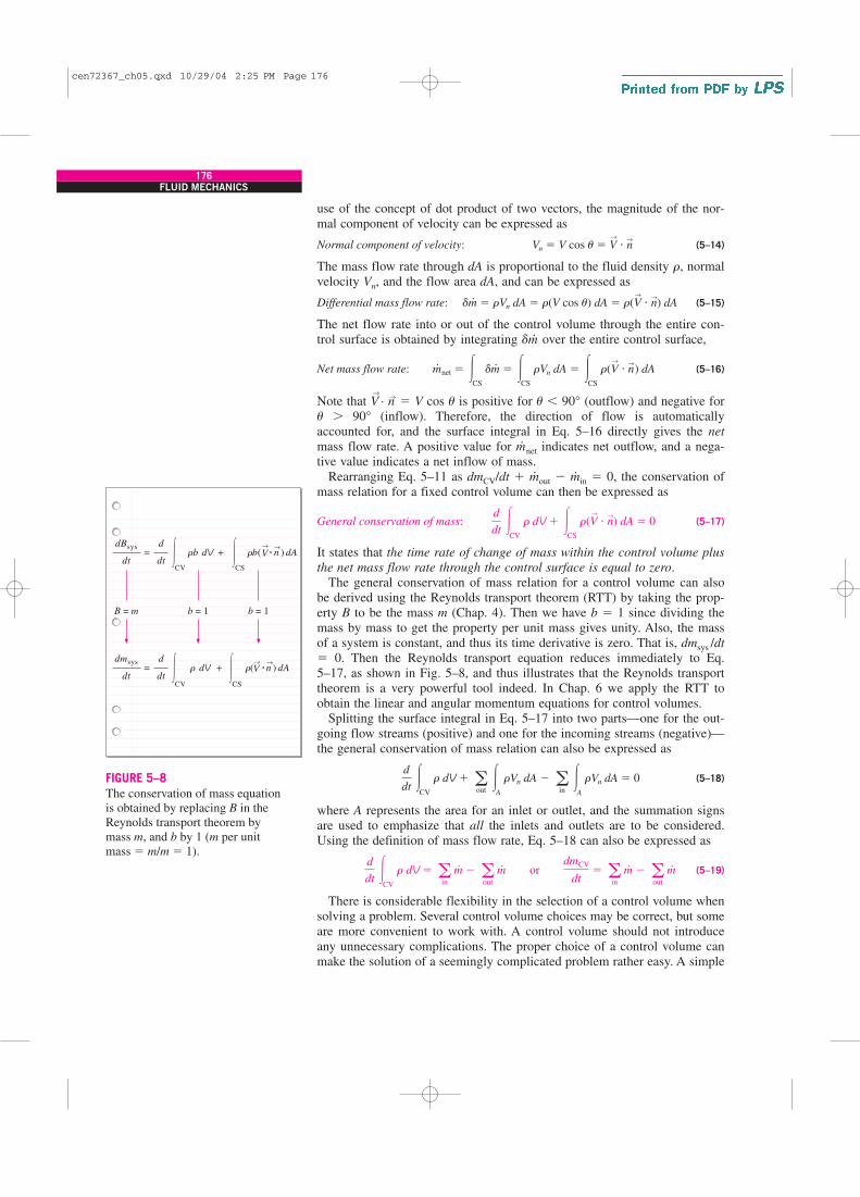
the net mass flow rate through the control surface is equal to zero.The general conservation of mass relation for a control volume can also
be derived using the Reynolds transport theorem (RTT) by taking the prop-erty B to be the mass m (Chap. 4). Then we have b � 1 since dividing themass by mass to get the property per unit mass gives unity. Also, the massof a system is constant, and thus its time derivative is zero. That is, dmsys /dt
� 0. Then the Reynolds transport equation reduces immediately to Eq.5–17, as shown in Fig. 5–8, and thus illustrates that the Reynolds transporttheorem is a very powerful tool indeed. In Chap. 6 we apply the RTT toobtain the linear and angular momentum equations for control volumes.
Splitting the surface integral in Eq. 5–17 into two parts—one for the out-going flow streams (positive) and one for the incoming streams (negative)—the general conservation of mass relation can also be expressed as
(5–18)
where A represents the area for an inlet or outlet, and the summation signsare used to emphasize that all the inlets and outlets are to be considered.Using the definition of mass flow rate, Eq. 5–18 can also be expressed as
(5–19)
There is considerable flexibility in the selection of a control volume whensolving a problem. Several control volume choices may be correct, but someare more convenient to work with. A control volume should not introduceany unnecessary complications. The proper choice of a control volume canmake the solution of a seemingly complicated problem rather easy. A simple
d
dt �
CV
r dV � ain
m#
� aout
m# or dmCV
dt� a
in
m#
� aout
m#
d
dt �
CV
r dV � aout
�A
rVn dA � ain
�A
rVn dA � 0
d
dt �
CV
r dV � �CS
r(V→
� n→) dA � 0
m#
net � �CS
dm#
� �CS
rVn dA � �CS
r(V→
� n→
) dA
dm#
� rVn dA � r(V cos u) dA � r(V→
� n→) dA
Vn � V cos u � V→
� n→
→→
→→= +
B = m b = 1 b = 1
dBsys
dtV
d
dtCV
� rb( · n ) dA
CS
�
= +dmsys
dtV
d
dtCV
� r( · n ) dA
CS
�r dV
rb dV
FIGURE 5–8
The conservation of mass equation is obtained by replacing B in theReynolds transport theorem by mass m, and b by 1 (m per unit mass � m/m � 1).
cen72367_ch05.qxd 10/29/04 2:25 PM Page 176
177CHAPTER 5
V
→n
AV
m = rVA
FIGURE 5–9
A control surface should always beselected normal to flow at all locationswhere it crosses the fluid flow to avoid
complications, even though the resultis the same.
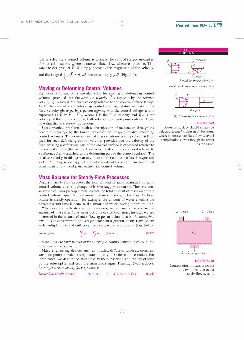
rule in selecting a control volume is to make the control surface normal to
flow at all locations where it crosses fluid flow, whenever possible. Thisway the dot product V
→· n
→simply becomes the magnitude of the velocity,
and the integral becomes simply rVA (Fig. 5–9).
Moving or Deforming Control VolumesEquations 5–17 and 5–18 are also valid for moving or deforming controlvolumes provided that the absolute velocity V
→is replaced by the relative
velocity V→
r , which is the fluid velocity relative to the control surface (Chap.4). In the case of a nondeforming control volume, relative velocity is thefluid velocity observed by a person moving with the control volume and isexpressed as V
→
r � V→
� V→
CV, where V→
is the fluid velocity and V→
CV is thevelocity of the control volume, both relative to a fixed point outside. Againnote that this is a vector subtraction.
Some practical problems (such as the injection of medication through theneedle of a syringe by the forced motion of the plunger) involve deformingcontrol volumes. The conservation of mass relations developed can still beused for such deforming control volumes provided that the velocity of thefluid crossing a deforming part of the control surface is expressed relative tothe control surface (that is, the fluid velocity should be expressed relative toa reference frame attached to the deforming part of the control surface). Therelative velocity in this case at any point on the control surface is expressedas V
→
r� V→
� V→
CS, where V→
CS is the local velocity of the control surface at thatpoint relative to a fixed point outside the control volume.
Mass Balance for Steady-Flow ProcessesDuring a steady-flow process, the total amount of mass contained within acontrol volume does not change with time (mCV � constant). Then the con-servation of mass principle requires that the total amount of mass entering acontrol volume equal the total amount of mass leaving it. For a garden hosenozzle in steady operation, for example, the amount of water entering thenozzle per unit time is equal to the amount of water leaving it per unit time.
When dealing with steady-flow processes, we are not interested in theamount of mass that flows in or out of a device over time; instead, we areinterested in the amount of mass flowing per unit time, that is, the mass flow
rate m.. The conservation of mass principle for a general steady-flow system
with multiple inlets and outlets can be expressed in rate form as (Fig. 5–10)
Steady flow: (5–20)
It states that the total rate of mass entering a control volume is equal to the
total rate of mass leaving it.Many engineering devices such as nozzles, diffusers, turbines, compres-
sors, and pumps involve a single stream (only one inlet and one outlet). Forthese cases, we denote the inlet state by the subscript 1 and the outlet stateby the subscript 2, and drop the summation signs. Then Eq. 5–20 reduces,for single-stream steady-flow systems, to
Steady flow (single stream): (5–21)m#
1 � m#
2 → r1V1 A1 � r2V2 A2
ain
m#
� aout
m# (kg/s)
�A
r(V→
� n→
) dA
m
CV
˙ 1 = 2 kg/s m2 = 3 kg/s
m3 = m1 + m2 = 5 kg/s˙ ˙ ˙
FIGURE 5–10
Conservation of mass principle for a two-inlet–one-outlet
steady-flow system.
Vu→
n
Vn = V cos u
A/cos uAV
m = r(V cos u)(A/cos u) = rVA
(a) Control surface at an angle to flow
(b) Control surface normal to flow
cen72367_ch05.qxd 10/29/04 2:25 PM Page 177

Special Case: Incompressible FlowThe conservation of mass relations can be simplified even further when thefluid is incompressible, which is usually the case for liquids. Canceling thedensity from both sides of the general steady-flow relation gives
Steady, incompressible flow: (5–22)
For single-stream steady-flow systems it becomes
Steady, incompressible flow (single stream): (5–23)
It should always be kept in mind that there is no such thing as a “conserva-tion of volume” principle. Therefore, the volume flow rates into and out of asteady-flow device may be different. The volume flow rate at the outlet ofan air compressor is much less than that at the inlet even though the massflow rate of air through the compressor is constant (Fig. 5–11). This is dueto the higher density of air at the compressor exit. For steady flow of liq-uids, however, the volume flow rates, as well as the mass flow rates, remainconstant since liquids are essentially incompressible (constant-density) sub-stances. Water flow through the nozzle of a garden hose is an example ofthe latter case.
The conservation of mass principle is based on experimental observationsand requires every bit of mass to be accounted for during a process. If youcan balance your checkbook (by keeping track of deposits and withdrawals,or by simply observing the “conservation of money” principle), you shouldhave no difficulty applying the conservation of mass principle to engineer-ing systems.
EXAMPLE 5–1 Water Flow through a Garden Hose Nozzle
A garden hose attached with a nozzle is used to fill a 10-gal bucket. The
inner diameter of the hose is 2 cm, and it reduces to 0.8 cm at the nozzle
exit (Fig. 5–12). If it takes 50 s to fill the bucket with water, determine
(a) the volume and mass flow rates of water through the hose, and (b) the
average velocity of water at the nozzle exit.
SOLUTION A garden hose is used to fill a water bucket. The volume and
mass flow rates of water and the exit velocity are to be determined.
Assumptions 1 Water is an incompressible substance. 2 Flow through the
hose is steady. 3 There is no waste of water by splashing.
Properties We take the density of water to be 1000 kg/m3 � 1 kg/L.
Analysis (a) Noting that 10 gal of water are discharged in 50 s, the volume
and mass flow rates of water are
(b) The cross-sectional area of the nozzle exit is
Ae � pr 2e � p(0.4 cm)2
� 0.5027 cm2� 0.5027 � 10�4 m2
m#
� rV#
� (1 kg/L)(0.757 L/s) � 0.757 kg/s
V#
�V
�t�
10 gal
50 s a3.7854 L
1 galb � 0.757 L/s
V#
1 � V#
2 → V1A1 � V2 A2
ain
V#
� aout
V# (m3/s)
178FLUID MECHANICS
m 1 = 2 kg/s
Air
compressor
m2 = 2 kg/s
V2 = 0.8 m3/s
V1 = 1.4 m3/s
FIGURE 5–11
During a steady-flow process,volume flow rates are not necessarilyconserved although mass flow rates are.
Nozzle
BucketGardenhose
FIGURE 5–12
Schematic for Example 5–1.
cen72367_ch05.qxd 10/29/04 2:25 PM Page 178

The volume flow rate through the hose and the nozzle is constant. Then the
average velocity of water at the nozzle exit becomes
Discussion It can be shown that the average velocity in the hose is 2.4 m/s.
Therefore, the nozzle increases the water velocity by over six times.
EXAMPLE 5–2 Discharge of Water from a Tank
A 4-ft-high, 3-ft-diameter cylindrical water tank whose top is open to the
atmosphere is initially filled with water. Now the discharge plug near the bot-
tom of the tank is pulled out, and a water jet whose diameter is 0.5 in
streams out (Fig. 5–13). The average velocity of the jet is given by
V � , where h is the height of water in the tank measured from the
center of the hole (a variable) and g is the gravitational acceleration. Deter-
mine how long it will take for the water level in the tank to drop to 2 ft from
the bottom.
SOLUTION The plug near the bottom of a water tank is pulled out. The
time it will take for half of the water in the tank to empty is to be deter-
mined.
Assumptions 1 Water is an incompressible substance. 2 The distance
between the bottom of the tank and the center of the hole is negligible com-
pared to the total water height. 3 The gravitational acceleration is 32.2 ft/s2.
Analysis We take the volume occupied by water as the control volume. The
size of the control volume decreases in this case as the water level drops,
and thus this is a variable control volume. (We could also treat this as a
fixed control volume that consists of the interior volume of the tank by disre-
garding the air that replaces the space vacated by the water.) This is obvi-
ously an unsteady-flow problem since the properties (such as the amount of
mass) within the control volume change with time.
The conservation of mass relation for a control volume undergoing any
process is given in the rate form as
(1)
During this process no mass enters the control volume (m.
in � 0), and the
mass flow rate of discharged water can be expressed as
(2)
where Ajet � pD2jet/4 is the cross-sectional area of the jet, which is constant.
Noting that the density of water is constant, the mass of water in the tank at
any time is
(3)
where Atank � pD2tank/4 is the base area of the cylindrical tank. Substituting
Eqs. 2 and 3 into the mass balance relation (Eq. 1) gives
�r22ghAjet �d(rAtankh)
dt→ �r22gh(pD2
jet /4) �r(pD2
tank/4) dh
dt
mCV � rV � rAtankh
m#
out � (rVA)out � r22ghAjet
m#
in � m#
out �dmCV
dt
12gh
Ve �V#
Ae
�0.757 L/s
0.5027 � 10�4 m2 a 1 m3
1000 Lb � 15.1 m/s
179CHAPTER 5
Water
Air
0 Dtank
Djeth2
h0
h
FIGURE 5–13
Schematic for Example 5–2.
cen72367_ch05.qxd 10/29/04 2:25 PM Page 179

Canceling the densities and other common terms and separating the vari-
ables give
Integrating from t � 0 at which h � h0 to t � t at which h � h2 gives
Substituting, the time of discharge is determined to be
Therefore, half of the tank will be emptied in 12.6 min after the discharge
hole is unplugged.
Discussion Using the same relation with h2 � 0 gives t � 43.1 min for the
discharge of the entire amount of water in the tank. Therefore, emptying the
bottom half of the tank takes much longer than emptying the top half. This
is due to the decrease in the average discharge velocity of water with
decreasing h.
5–3 � MECHANICAL ENERGY AND EFFICIENCY
Many fluid systems are designed to transport a fluid from one location toanother at a specified flow rate, velocity, and elevation difference, and thesystem may generate mechanical work in a turbine or it may consumemechanical work in a pump or fan during this process. These systems donot involve the conversion of nuclear, chemical, or thermal energy tomechanical energy. Also, they do not involve any heat transfer in any signif-icant amount, and they operate essentially at constant temperature. Suchsystems can be analyzed conveniently by considering the mechanical forms
of energy only and the frictional effects that cause the mechanical energy tobe lost (i.e., to be converted to thermal energy that usually cannot be usedfor any useful purpose).
The mechanical energy can be defined as the form of energy that can be
converted to mechanical work completely and directly by an ideal mechani-
cal device such as an ideal turbine. Kinetic and potential energies are thefamiliar forms of mechanical energy. Thermal energy is not mechanicalenergy, however, since it cannot be converted to work directly and com-pletely (the second law of thermodynamics).
A pump transfers mechanical energy to a fluid by raising its pressure, anda turbine extracts mechanical energy from a fluid by dropping its pressure.Therefore, the pressure of a flowing fluid is also associated with its mechan-ical energy. In fact, the pressure unit Pa is equivalent to Pa � N/m2 �
N · m/m3 � J/m3, which is energy per unit volume, and the product Pv orits equivalent P/r has the unit J/kg, which is energy per unit mass. Note thatpressure itself is not a form of energy. But a pressure force acting on a fluidthrough a distance produces work, called flow work, in the amount of P/rper unit mass. Flow work is expressed in terms of fluid properties, and it isconvenient to view it as part of the energy of a flowing fluid and call it flow
t �24 ft � 22 ft
232.2/2 ft/s2 a3 � 12 in
0.5 inb 2
� 757 s � 12.6 min
�t
0
dt � �D2
tank
D2jet22g
�h2
h0
dh
2h → t �
2h0 � 2h2
2g/2 aDtank
Djet
b 2
dt � �D2
tank
D2jet
dh
22gh
180FLUID MECHANICS
cen72367_ch05.qxd 10/29/04 2:25 PM Page 180

energy. Therefore, the mechanical energy of a flowing fluid can beexpressed on a unit-mass basis as (Fig. 5–14).
where P/r is the flow energy, V2/2 is the kinetic energy, and gz is the poten-
tial energy of the fluid, all per unit mass. Then the mechanical energychange of a fluid during incompressible flow becomes
(5–24)
Therefore, the mechanical energy of a fluid does not change during flow ifits pressure, density, velocity, and elevation remain constant. In the absenceof any losses, the mechanical energy change represents the mechanicalwork supplied to the fluid (if �emech � 0) or extracted from the fluid (if�emech � 0).
Consider a container of height h filled with water, as shown in Fig. 5–15,with the reference level selected at the bottom surface. The gage pressureand the potential energy per unit mass are, respectively, PA � 0 and peA
� gh at point A at the free surface, and PB � rgh and peB � 0 at point B atthe bottom of the container. An ideal hydraulic turbine would produce thesame work per unit mass wturbine � gh whether it receives water (or anyother fluid with constant density) from the top or from the bottom of thecontainer. Note that we are also assuming ideal flow (no irreversible losses)through the pipe leading from the tank to the turbine. Therefore, the totalmechanical energy of water at the bottom is equivalent to that at the top.
The transfer of mechanical energy is usually accomplished by a rotatingshaft, and thus mechanical work is often referred to as shaft work. A pumpor a fan receives shaft work (usually from an electric motor) and transfers itto the fluid as mechanical energy (less frictional losses). A turbine, on theother hand, converts the mechanical energy of a fluid to shaft work. In theabsence of any irreversibilities such as friction, mechanical energy can beconverted entirely from one mechanical form to another, and the mechani-
cal efficiency of a device or process can be defined as (Fig. 5–16)
(5–25)
A conversion efficiency of less than 100 percent indicates that conversion isless than perfect and some losses have occurred during conversion. A
hmech �Mechanical energy output
Mechanical energy input�
Emech, out
Emech, in
� 1 �Emech, loss
Emech, in
�emech �P2 � P1
r�
V 22 � V 2
1
2� g(z2 � z1) (kJ/kg)
emech �P
r�
V 2
2� gz
181CHAPTER 5
h = 10 m
m = 2 kg/s
Atmosphere
0
z
= m
= (2 kg/s)(9.81 m/s2)(10 m)
= 196 W
Patm
Wmax
W
= m = mghP 1 – P atm–––––––––
rgh –––
·
· · · ·
·
1
rr
FIGURE 5–14
In the absence of any changes in flowvelocity and elevation, the power
produced by an ideal hydraulic turbineis proportional to the pressure drop
of water across the turbine.
m0
zh
pe = ghP = 0
P = rghpe = 0
A
B
m·
Wmax = mgh· · Wmax = mgh
· ·
·
FIGURE 5–15
The mechanical energy of water at the bottom of a container is equal
to the mechanical energy at any depth including the free surface
of the container.
cen72367_ch05.qxd 10/29/04 2:25 PM Page 181
mechanical efficiency of 97 percent indicates that 3 percent of the mechani-cal energy input is converted to thermal energy as a result of frictional heat-ing, and this will manifest itself as a slight rise in the temperature of thefluid.
In fluid systems, we are usually interested in increasing the pressure,velocity, and/or elevation of a fluid. This is done by supplying mechanical
energy to the fluid by a pump, a fan, or a compressor (we will refer to all ofthem as pumps). Or we are interested in the reverse process of extracting
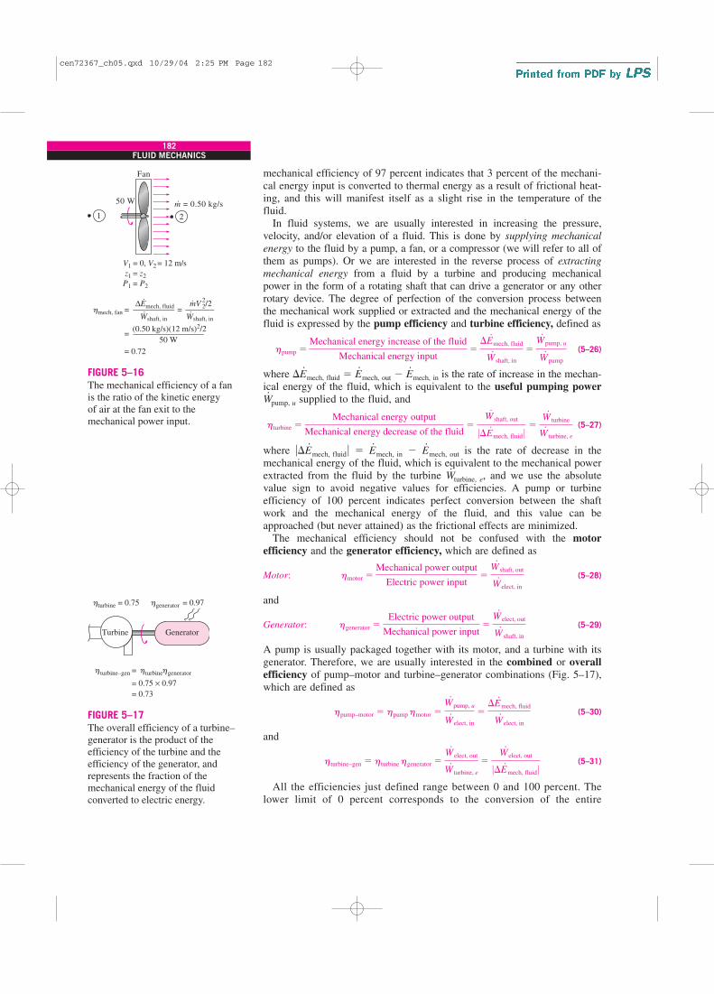
mechanical energy from a fluid by a turbine and producing mechanicalpower in the form of a rotating shaft that can drive a generator or any otherrotary device. The degree of perfection of the conversion process betweenthe mechanical work supplied or extracted and the mechanical energy of thefluid is expressed by the pump efficiency and turbine efficiency, defined as
(5–26)
where �E.
mech, fluid � E.
mech, out � E.
mech, in is the rate of increase in the mechan-ical energy of the fluid, which is equivalent to the useful pumping power
W.
pump, u supplied to the fluid, and
(5–27)
where ��E.
mech, fluid� � E.
mech, in � E.
mech, out is the rate of decrease in themechanical energy of the fluid, which is equivalent to the mechanical powerextracted from the fluid by the turbine W
.turbine, e, and we use the absolute
value sign to avoid negative values for efficiencies. A pump or turbine efficiency of 100 percent indicates perfect conversion between the shaftwork and the mechanical energy of the fluid, and this value can beapproached (but never attained) as the frictional effects are minimized.
The mechanical efficiency should not be confused with the motor
efficiency and the generator efficiency, which are defined as
Motor: (5–28)
and
Generator: (5–29)
A pump is usually packaged together with its motor, and a turbine with itsgenerator. Therefore, we are usually interested in the combined or overall
efficiency of pump–motor and turbine–generator combinations (Fig. 5–17),which are defined as
(5–30)
and
(5–31)
All the efficiencies just defined range between 0 and 100 percent. Thelower limit of 0 percent corresponds to the conversion of the entire
hturbine–gen � hturbine hgenerator �W#
elect, out
W#
turbine, e
�W#
elect, out
0�E#
mech, fluid 0
hpump–motor � hpump hmotor �W#
pump, u
W#
elect, in
��E#
mech, fluid
W#
elect, in
hgenerator �Electric power output
Mechanical power input�
W#
elect, out
W#
shaft, in
hmotor �Mechanical power output
Electric power input�
W#
shaft, out
W#
elect, in
hturbine �Mechanical energy output
Mechanical energy decrease of the fluid�
W#
shaft, out
0�E#
mech, fluid 0 �W#
turbine
W#
turbine, e
hpump �Mechanical energy increase of the fluid
Mechanical energy input�
�E#
mech, fluid
W#
shaft, in
�W#
pump, u
W#
pump
182FLUID MECHANICS
Generator
=
= 0.75 × 0.97
= 0.73
Turbine
turbine–gen
= 0.75 turbine = 0.97 generator
turbine generator
h h
h h h
FIGURE 5–17
The overall efficiency of a turbine–generator is the product of theefficiency of the turbine and theefficiency of the generator, andrepresents the fraction of themechanical energy of the fluidconverted to electric energy.
m = 0.50 kg/s
Fan
50 W ·
1 2
= 0, V1 = 12 m/s
= z2z1
= P2P1
=
=
= 0.72
hmech, fan = ∆Emech, fluid––––––––––
Wshaft, in
(0.50 kg/s)(12 m/s)2/2–––––––––––––––––
50 W
·
· mV
22/2
–––––––Wshaft, in
·
·
V2
FIGURE 5–16
The mechanical efficiency of a fan is the ratio of the kinetic energy of air at the fan exit to the mechanical power input.
cen72367_ch05.qxd 10/29/04 2:25 PM Page 182

mechanical or electric energy input to thermal energy, and the device inthis case functions like a resistance heater. The upper limit of 100 percentcorresponds to the case of perfect conversion with no friction or other irre-versibilities, and thus no conversion of mechanical or electric energy tothermal energy.
EXAMPLE 5–3 Performance of a Hydraulic Turbine–Generator
The water in a large lake is to be used to generate electricity by the installa-
tion of a hydraulic turbine–generator at a location where the depth of the
water is 50 m (Fig. 5–18). Water is to be supplied at a rate of 5000 kg/s. If
the electric power generated is measured to be 1862 kW and the generator
efficiency is 95 percent, determine (a) the overall efficiency of the tur-
bine–generator, (b) the mechanical efficiency of the turbine, and (c) the
shaft power supplied by the turbine to the generator.
SOLUTION A hydraulic turbine–generator is to generate electricity from the
water of a lake. The overall efficiency, the turbine efficiency, and the shaft
power are to be determined.
Assumptions 1 The elevation of the lake remains constant. 2 The mechani-
cal energy of water at the turbine exit is negligible.
Properties The density of water can be taken to be r � 1000 kg/m3.
Analysis (a) We take the bottom of the lake as the reference level for conve-
nience. Then kinetic and potential energies of water are zero, and the
change in its mechanical energy per unit mass becomes
Then the rate at which mechanical energy is supplied to the turbine by the
fluid and the overall efficiency become
(b) Knowing the overall and generator efficiencies, the mechanical efficiency
of the turbine is determined from
(c) The shaft power output is determined from the definition of mechanical
efficiency,
W#
shaft, out � hturbine 0�E#
mech, fluid 0 � (0.80)(2455 kW) � 1964 kW
hturbine–gen � hturbine hgenerator → hturbine �hturbine–gen
hgenerator
�0.76
0.95� 0.80
hoverall � hturbine–gen �W#
elect, out
0�E#
mech, fluid 0 �1862 kW
2455 kW� 0.76
0�E#
mech, fluid 0 � m#(emech, in � emech, out) � (5000 kg/s)(0.491 kJ/kg) � 2455 kW
emech, in � emech, out �P
r� 0 � gh � (9.81 m/s2)(50 m)a 1 kJ/kg
1000 m2/s2b� 0.491 kJ/kg
183CHAPTER 5
GeneratorTurbine
1862 kW
m = 5000 kg/s
h = 50 m
·
Lake= 0.95 generatorh
FIGURE 5–18
Schematic for Example 5–3.
cen72367_ch05.qxd 10/29/04 2:25 PM Page 183

Discussion Note that the lake supplies 2455 kW of mechanical energy to
the turbine, which converts 1964 kW of it to shaft work that drives the gen-
erator, which generates 1862 kW of electric power. There are irreversible
losses through each component.
EXAMPLE 5–4 Conservation of Energy for
an Oscillating Steel Ball
The motion of a steel ball in a hemispherical bowl of radius h shown in Fig.
5–19 is to be analyzed. The ball is initially held at the highest location at
point A, and then it is released. Obtain relations for the conservation of
energy of the ball for the cases of frictionless and actual motions.
SOLUTION A steel ball is released in a bowl. Relations for the energy bal-
ance are to be obtained.
Assumptions The motion is frictionless, and thus friction between the ball,
the bowl, and the air is negligible.
Analysis When the ball is released, it accelerates under the influence of
gravity, reaches a maximum velocity (and minimum elevation) at point B at
the bottom of the bowl, and moves up toward point C on the opposite side.
In the ideal case of frictionless motion, the ball will oscillate between points
A and C. The actual motion involves the conversion of the kinetic and poten-
tial energies of the ball to each other, together with overcoming resistance to
motion due to friction (doing frictional work). The general energy balance for
any system undergoing any process is
Net energy transfer Change in internal, kinetic,by heat, work, and mass potential, etc., energies
Then the energy balance for the ball for a process from point 1 to point 2
becomes
or
since there is no energy transfer by heat or mass and no change in the inter-
nal energy of the ball (the heat generated by frictional heating is dissipated to
V 21
2� gz1 �
V 22
2� gz2 � wfriction
�wfriction � (ke2 � pe2) � (ke1 � pe1)
E in � Eout � �E system
184FLUID MECHANICS
Steelball
0
z
hA
B
C
1
2FIGURE 5–19
Schematic for Example 5–4.
cen72367_ch05.qxd 10/29/04 2:25 PM Page 184

the surrounding air). The frictional work term wfriction is often expressed as eloss
to represent the loss (conversion) of mechanical energy into thermal energy.
For the idealized case of frictionless motion, the last relation reduces to
where the value of the constant is C � gh. That is, when the frictional
effects are negligible, the sum of the kinetic and potential energies of the
ball remains constant.
Discussion This is certainly a more intuitive and convenient form of the
conservation of energy equation for this and other similar processes such as
the swinging motion of the pendulum of a wall clock. The relation obtained
is analogous to the Bernoulli equation derived in Section 5–4.
Most processes encountered in practice involve only certain forms ofenergy, and in such cases it is more convenient to work with the simplifiedversions of the energy balance. For systems that involve only mechanical
forms of energy and its transfer as shaft work, the conservation of energyprinciple can be expressed conveniently as
(5–32)
where Emech, loss represents the conversion of mechanical energy to thermalenergy due to irreversibilities such as friction. For a system in steady operation, the mechanical energy balance becomes E
.mech, in � E
.mech, out
� E.
mech, loss (Fig. 5–20).
5–4 � THE BERNOULLI EQUATION
The Bernoulli equation is an approximate relation between pressure,
velocity, and elevation, and is valid in regions of steady, incompressible
flow where net frictional forces are negligible (Fig. 5–21). Despite its sim-plicity, it has proven to be a very powerful tool in fluid mechanics. In thissection, we derive the Bernoulli equation by applying the conservation of
linear momentum principle, and we demonstrate both its usefulness and itslimitations.
The key approximation in the derivation of the Bernoulli equation is thatviscous effects are negligibly small compared to inertial, gravitational, and
pressure effects. Since all fluids have viscosity (there is no such thing as an“inviscid fluid”), this approximation cannot be valid for an entire flow fieldof practical interest. In other words, we cannot apply the Bernoulli equationeverywhere in a flow, no matter how small the fluid’s viscosity. However, itturns out that the approximation is reasonable in certain regions of manypractical flows. We refer to such regions as inviscid regions of flow, and westress that they are not regions where the fluid itself is inviscid or friction-less, but rather they are regions where net viscous or frictional forces arenegligibly small compared to other forces acting on fluid particles.
Care must be exercised when applying the Bernoulli equation since it isan approximation that applies only to inviscid regions of flow. In general,frictional effects are always important very close to solid walls (boundary
layers) and directly downstream of bodies (wakes). Thus, the Bernoulli
Emech, in � Emech, out � �Emech, system � Emech, loss
V 21
2� gz1 �
V 22
2� gz2 or V 2
2� gz � C � constant
185CHAPTER 5
1 = 2z2 = z1 + h
P1 = P2 = Patm
Emech, in = Emech, out + Emech, loss· · ·
·Wpump + mgz1 = mgz2 + Emech, loss· · ·
·Wpump = mgh + Emech, loss· ·
h
2
Steady flow
1
V
Wpump·
V
FIGURE 5–20
Most fluid flow problems involvemechanical forms of energy only, and
such problems are conveniently solvedby using a mechanical energy balance.
Bernoulli equation valid
Bernoulli equation not valid
FIGURE 5–21
The Bernoulli equation is anapproximate equation that is valid
only in inviscid regions of flow wherenet viscous forces are negligibly smallcompared to inertial, gravitational, or
pressure forces. Such regions occuroutside of boundary layers and wakes.
cen72367_ch05.qxd 10/29/04 2:25 PM Page 185

approximation is typically useful in flow regions outside of boundary layersand wakes, where the fluid motion is governed by the combined effects ofpressure and gravity forces.
The motion of a particle and the path it follows are described by thevelocity vector as a function of time and space coordinates and the initialposition of the particle. When the flow is steady (no change with time at aspecified location), all particles that pass through the same point follow thesame path (which is the streamline), and the velocity vectors remain tangentto the path at every point.
Acceleration of a Fluid ParticleOften it is convenient to describe the motion of a particle in terms of its dis-tance s along a streamline together with the radius of curvature along thestreamline. The velocity of the particle is related to the distance by V
� ds/dt, which may vary along the streamline. In two-dimensional flow, theacceleration can be decomposed into two components: streamwise accelera-
tion as along the streamline and normal acceleration an in the direction nor-mal to the streamline, which is given as an � V2/R. Note that streamwiseacceleration is due to a change in speed along a streamline, and normalacceleration is due to a change in direction. For particles that move along astraight path, an � 0 since the radius of curvature is infinity and thus thereis no change in direction. The Bernoulli equation results from a force bal-ance along a streamline.
One may be tempted to think that acceleration is zero in steady flow sinceacceleration is the rate of change of velocity with time, and in steady flowthere is no change with time. Well, a garden hose nozzle tells us that thisunderstanding is not correct. Even in steady flow and thus constant massflow rate, water accelerates through the nozzle (Fig. 5–22 as discussed inChap. 4). Steady simply means no change with time at a specified location,
but the value of a quantity may change from one location to another. In thecase of a nozzle, the velocity of water remains constant at a specified point,but it changes from the inlet to the exit (water accelerates along the nozzle).
Mathematically, this can be expressed as follows: We take the velocity Vof a fluid particle to be a function of s and t. Taking the total differential ofV(s, t) and dividing both sides by dt give
(5–33)
In steady flow ∂V/∂t � 0 and thus V � V(s), and the acceleration in the s-direction becomes
(5–34)
where V � ds/dt if we are following a fluid particle as it moves along astreamline. Therefore, acceleration in steady flow is due to the change ofvelocity with position.
Derivation of the Bernoulli EquationConsider the motion of a fluid particle in a flow field in steady flowdescribed in detail in Chap. 4. Applying Newton’s second law (which is
as �dV
dt�
V
s ds
dt�
V
s V � V
dV
ds
dV �V
s ds �
V
t dt and dV
dt�
V
s ds
dt�
V
t
186FLUID MECHANICS
FIGURE 5–22
During steady flow, a fluid may notaccelerate in time at a fixed point, butit may accelerate in space.
cen72367_ch05.qxd 10/29/04 2:25 PM Page 186

referred to as the conservation of linear momentum relation in fluidmechanics) in the s-direction on a particle moving along a streamline gives
(5–35)
In regions of flow where net frictional forces are negligible, the significantforces acting in the s-direction are the pressure (acting on both sides) andthe component of the weight of the particle in the s-direction (Fig. 5–23).Therefore, Eq. 5–35 becomes
(5–36)
where u is the angle between the normal of the streamline and the vertical z-axis at that point, m � rV � r dA ds is the mass, W � mg � rg dA ds isthe weight of the fluid particle, and sin u � dz/ds. Substituting,
(5–37)
Canceling dA from each term and simplifying,
(5–38)
Noting that V dV � d(V2) and dividing each term by r gives
(5–39)
Integrating (Fig. 5–24),
Steady flow: (5–40)
since the last two terms are exact differentials. In the case of incompressibleflow, the first term also becomes an exact differential, and its integrationgives
Steady, incompressible flow: (5–41)
This is the famous Bernoulli equation, which is commonly used in fluidmechanics for steady, incompressible flow along a streamline in inviscid
P
r�
V 2
2� gz � constant (along a streamline)
� dP
r�
V 2
2� gz � constant (along a streamline)
dP
r�
12 d(V 2) � g dz � 0
12
�dP � rg dz � rV dV
�dP dA � rg dA ds dz
ds� r dA ds V
dV
ds
P dA � (P � dP) dA � W sin u � mV dV
ds
a Fs � mas
187CHAPTER 5
General:
(Steady flow along a streamline)
Incompressible flow (r = constant):
� –– + + gz = constantdP ––2
–– + + gz = constantP ––2
V2
V2
r
r
FIGURE 5–24
The Bernoulli equation is derivedassuming incompressible flow,and thus it should not be used
for flows with significantcompressibility effects.
z
x
W
sn
P dA
(P + dP) dA
Steady flow along a streamline
dx
dzds
u
u
ds
FIGURE 5–23
The forces acting on a fluid particle along a streamline.
cen72367_ch05.qxd 10/29/04 2:25 PM Page 187

regions of flow. The value of the constant can be evaluated at any point onthe streamline where the pressure, density, velocity, and elevation areknown. The Bernoulli equation can also be written between any two pointson the same streamline as
Steady, incompressible flow: (5–42)
The Bernoulli equation is obtained from the conservation of momentumfor a fluid particle moving along a streamline. It can also be obtained fromthe first law of thermodynamics applied to a steady-flow system, as shownin Section 5–7.
The Bernoulli equation was first stated in words by the Swiss mathemati-cian Daniel Bernoulli (1700–1782) in a text written in 1738 when he wasworking in St. Petersburg, Russia. It was later derived in equation form byhis associate Leonhard Euler in 1755. We recognize V2/2 as kinetic energy,
gz as potential energy, and P/r as flow energy, all per unit mass. Therefore,the Bernoulli equation can be viewed as an expression of mechanical energy
balance and can be stated as follows (Fig. 5–25):
The sum of the kinetic, potential, and flow energies of a fluid particle isconstant along a streamline during steady flow when the compressibility and frictional effects are negligible.
The kinetic, potential, and flow energies are the mechanical forms ofenergy, as discussed in Section 5–3, and the Bernoulli equation can beviewed as the “conservation of mechanical energy principle.” This is equiva-lent to the general conservation of energy principle for systems that do notinvolve any conversion of mechanical energy and thermal energy to eachother, and thus the mechanical energy and thermal energy are conserved sep-arately. The Bernoulli equation states that during steady, incompressible flowwith negligible friction, the various forms of mechanical energy are con-verted to each other, but their sum remains constant. In other words, there isno dissipation of mechanical energy during such flows since there is no fric-tion that converts mechanical energy to sensible thermal (internal) energy.
Recall that energy is transferred to a system as work when a force isapplied to a system through a distance. In the light of Newton’s second lawof motion, the Bernoulli equation can also be viewed as: The work done by
the pressure and gravity forces on the fluid particle is equal to the increase
in the kinetic energy of the particle.Despite the highly restrictive approximations used in its derivation, the
Bernoulli equation is commonly used in practice since a variety of practicalfluid flow problems can be analyzed to reasonable accuracy with it. This isbecause many flows of practical engineering interest are steady (or at leaststeady in the mean), compressibility effects are relatively small, and netfrictional forces are negligible in regions of interest in the flow.
Force Balance across StreamlinesIt is left as an exercise to show that a force balance in the direction n normalto the streamline yields the following relation applicable across the stream-lines for steady, incompressible flow:
(5–43)P
r� �
V 2
R dn � gz � constant (across streamlines)
P1
r�
V 21
2� gz1 �
P2
r�
V 22
2� gz2
188FLUID MECHANICS
–– + gz = constant
Flow
energy
––
Potential
energy
Kinetic
energy
FIGURE 5–25
The Bernoulli equation states that thesum of the kinetic, potential, and flowenergies of a fluid particle is constantalong a streamline during steady flow.
cen72367_ch05.qxd 10/29/04 2:25 PM Page 188

For flow along a straight line, R → and thus relation (Eq. 5–44) reducesto P/r � gz � constant or P � �rgz � constant, which is an expressionfor the variation of hydrostatic pressure with vertical distance for a station-ary fluid body. Therefore, the variation of pressure with elevation in steady,incompressible flow along a straight line is the same as that in the stationaryfluid (Fig. 5–26).
Unsteady, Compressible FlowSimilarly, using both terms in the acceleration expression (Eq. 5–33), it canbe shown that the Bernoulli equation for unsteady, compressible flow is
Unsteady, compressible flow: (5–44)
Static, Dynamic, and Stagnation PressuresThe Bernoulli equation states that the sum of the flow, kinetic, and potentialenergies of a fluid particle along a streamline is constant. Therefore, thekinetic and potential energies of the fluid can be converted to flow energy(and vice versa) during flow, causing the pressure to change. This phenome-non can be made more visible by multiplying the Bernoulli equation by thedensity r,
(5–45)
Each term in this equation has pressure units, and thus each term representssome kind of pressure:
• P is the static pressure (it does not incorporate any dynamic effects); itrepresents the actual thermodynamic pressure of the fluid. This is thesame as the pressure used in thermodynamics and property tables.
• rV2/2 is the dynamic pressure; it represents the pressure rise when thefluid in motion is brought to a stop isentropically.
• rgz is the hydrostatic pressure, which is not pressure in a real sensesince its value depends on the reference level selected; it accounts for theelevation effects, i.e., of fluid weight on pressure.
The sum of the static, dynamic, and hydrostatic pressures is called the total
pressure. Therefore, the Bernoulli equation states that the total pressure
along a streamline is constant.The sum of the static and dynamic pressures is called the stagnation
pressure, and it is expressed as
(5–46)
The stagnation pressure represents the pressure at a point where the fluid isbrought to a complete stop isentropically. The static, dynamic, and stagna-tion pressures are shown in Fig. 5–27. When static and stagnation pressuresare measured at a specified location, the fluid velocity at that location canbe calculated from
(5–47)V �B2(Pstag � P)
r
Pstag � P � r V 2
2 (kPa)
P � r V 2
2� rgz � constant (along a streamline)
� dP
r� �
V
t ds �
V˛
2
2� gz � constant
189CHAPTER 5
Stationary fluid
A
z z
B
C
D
PB – PA = PD – PC
Flowing fluid
FIGURE 5–26
The variation of pressure withelevation in steady, incompressible
flow along a straight line is the same as that in the stationary fluid
(but this is not the case for a curved flow section).
Static
pressure, P
Stagnation
pressure, Pstag
Stagnation
point
2(Pstag – P)√
Dynamic
pressure
Pitot
tube
Piezometer
––2
V
=V
V2
r
r
FIGURE 5–27
The static, dynamic, and stagnation pressures.
cen72367_ch05.qxd 10/29/04 2:25 PM Page 189

Equation 5–47 is useful in the measurement of flow velocity when a com-bination of a static pressure tap and a Pitot tube is used, as illustrated in Fig.5–27. A static pressure tap is simply a small hole drilled into a wall suchthat the plane of the hole is parallel to the flow direction. It measures the sta-tic pressure. A Pitot tube is a small tube with its open end aligned into theflow so as to sense the full impact pressure of the flowing fluid. It measuresthe stagnation pressure. In situations in which the static and stagnation pres-sure of a flowing liquid are greater than atmospheric pressure, a vertical trans-parent tube called a piezometer tube (or simply a piezometer) can beattached to the pressure tap and to the Pitot tube, as sketched in Fig. 5–27.The liquid rises in the piezometer tube to a column height (head) that is pro-portional to the pressure being measured. If the pressures to be measured arebelow atmospheric, or if measuring pressures in gases, piezometer tubes donot work. However, the static pressure tap and Pitot tube can still be used, butthey must be connected to some other kind of pressure measurement devicesuch as a U-tube manometer or a pressure transducer (Chap. 3). Sometimesit is convenient to integrate static pressure holes on a Pitot probe. The resultis a Pitot-static probe, as shown in Fig. 5–28 and discussed in more detail inChap. 8. A Pitot-static probe connected to a pressure transducer or amanometer measures the dynamic pressure (and thus fluid velocity) directly.
When the static pressure is measured by drilling a hole in the tube wall,care must be exercised to ensure that the opening of the hole is flush withthe wall surface, with no extrusions before or after the hole (Fig. 5–29).Otherwise the reading will incorporate some dynamic effects, and thus itwill be in error.
When a stationary body is immersed in a flowing stream, the fluid isbrought to a stop at the nose of the body (the stagnation point). The flowstreamline that extends from far upstream to the stagnation point is calledthe stagnation streamline (Fig. 5–30). For a two-dimensional flow in thexy-plane, the stagnation point is actually a line parallel the z-axis, and thestagnation streamline is actually a surface that separates fluid that flowsover the body from fluid that flows under the body. In an incompressibleflow, the fluid decelerates nearly isentropically from its free-stream value tozero at the stagnation point, and the pressure at the stagnation point is thusthe stagnation pressure.
Limitations on the Use of the Bernoulli EquationThe Bernoulli equation (Eq. 5–41) is one of the most frequently used andmisused equations in fluid mechanics. Its versatility, simplicity, and ease ofuse make it a very valuable tool for use in analysis, but the same attributesalso make it very tempting to misuse. Therefore, it is important to under-stand the restrictions on its applicability and observe the limitations on itsuse, as explained here:
1. Steady flow The first limitation on the Bernoulli equation is that it isapplicable to steady flow. Therefore, it should not be used during thetransient start-up and shut-down periods, or during periods of change inthe flow conditions. Note that there is an unsteady form of the Bernoulliequation (Eq. 5–44), discussion of which is beyond the scope of thepresent text (see Panton, 1996).
190FLUID MECHANICS
Stagnation pressure hole
Static pressure holes
FIGURE 5–28
Close-up of a Pitot-static probe,showing the stagnation pressure hole and two of the five staticcircumferential pressure holes.
Photo by Po-Ya Abel Chuang. Used by permission.
High Correct Low
FIGURE 5–29
Careless drilling of the static pressuretap may result in an erroneous readingof the static pressure.
Stagnation streamline
FIGURE 5–30
Streaklines produced by colored fluidintroduced upstream of an airfoil;since the flow is steady, the streaklinesare the same as streamlines andpathlines. The stagnation streamline is marked.
Courtesy ONERA. Photograph by Werlé.
cen72367_ch05.qxd 10/29/04 2:25 PM Page 190

2. Frictionless flow Every flow involves some friction, no matter howsmall, and frictional effects may or may not be negligible. The situationis complicated even more by the amount of error that can be tolerated. Ingeneral, frictional effects are negligible for short flow sections withlarge cross sections, especially at low flow velocities. Frictional effectsare usually significant in long and narrow flow passages, in the wakeregion downstream of an object, and in diverging flow sections such asdiffusers because of the increased possibility of the fluid separating fromthe walls in such geometries. Frictional effects are also significant nearsolid surfaces, and thus the Bernoulli equation is usually applicablealong a streamline in the core region of the flow, but not along astreamline close to the surface (Fig. 5–31).
A component that disturbs the streamlined structure of flow and thuscauses considerable mixing and backflow such as a sharp entrance of atube or a partially closed valve in a flow section can make the Bernoulliequation inapplicable.
3. No shaft work The Bernoulli equation was derived from a forcebalance on a particle moving along a streamline. Therefore, theBernoulli equation is not applicable in a flow section that involves apump, turbine, fan, or any other machine or impeller since such devicesdestroy the streamlines and carry out energy interactions with the fluidparticles. When the flow section considered involves any of thesedevices, the energy equation should be used instead to account for theshaft work input or output. However, the Bernoulli equation can still beapplied to a flow section prior to or past a machine (assuming, of course,that the other restrictions on its use are satisfied). In such cases, theBernoulli constant changes from upstream to downstream of the device.
4. Incompressible flow One of the assumptions used in the derivation ofthe Bernoulli equation is that r� constant and thus the flow isincompressible. This condition is satisfied by liquids and also by gasesat Mach numbers less than about 0.3 since compressibility effects andthus density variations of gases are negligible at such relatively low
191CHAPTER 5
A fan
Suddenexpansion
Long and narrowtubes
A heating section
Flow througha valve
2
2
2
21
1
1
1
1 2
Boundary layers
Wakes
FIGURE 5–31
Frictional effects and componentsthat disturb the streamlinedstructure of flow in a flow
section make the Bernoulli equation invalid.
cen72367_ch05.qxd 10/29/04 2:25 PM Page 191

velocities. Note that there is a compressible form of the Bernoulliequation (Eqs. 5–40 and 5–44).
5. No heat transfer The density of a gas is inversely proportional totemperature, and thus the Bernoulli equation should not be used for flowsections that involve significant temperature change such as heating orcooling sections.
6. Flow along a streamline Strictly speaking, the Bernoulli equationP/r � V2/2 � gz � C is applicable along a streamline, and the value of the constant C, in general, is different for different streamlines. Butwhen a region of the flow is irrotational, and thus there is no vorticity
in the flow field, the value of the constant C remains the same for allstreamlines, and, therefore, the Bernoulli equation becomes applicableacross streamlines as well (Fig. 5–32). Therefore, we do not need to beconcerned about the streamlines when the flow is irrotational, and wecan apply the Bernoulli equation between any two points in theirrotational region of the flow (Chap. 10).
We derived the Bernoulli equation by considering two-dimensional flowin the xz-plane for simplicity, but the equation is valid for general three-dimensional flow as well, as long as it is applied along the same streamline.We should always keep in mind the assumptions used in the derivation ofthe Bernoulli equation and make sure that they are not violated.
Hydraulic Grade Line (HGL)
and Energy Grade Line (EGL)It is often convenient to represent the level of mechanical energy graphicallyusing heights to facilitate visualization of the various terms of the Bernoulliequation. This is done by dividing each term of the Bernoulli equation by gto give
(5–48)
Each term in this equation has the dimension of length and represents somekind of “head” of a flowing fluid as follows:
• P/rg is the pressure head; it represents the height of a fluid column thatproduces the static pressure P.
• V2/2g is the velocity head; it represents the elevation needed for a fluid to reach the velocity V during frictionless free fall.
• z is the elevation head; it represents the potential energy of the fluid.
Also, H is the total head for the flow. Therefore, the Bernoulli equation canbe expressed in terms of heads as: The sum of the pressure, velocity, and
elevation heads along a streamline is constant during steady flow when the
compressibility and frictional effects are negligible (Fig. 5–33).If a piezometer (measures static pressure) is tapped into a pipe, as shown
in Fig. 5–34, the liquid would rise to a height of P/rg above the pipe center.The hydraulic grade line (HGL) is obtained by doing this at several loca-tions along the pipe and drawing a line through the liquid levels in thepiezometers. The vertical distance above the pipe center is a measure ofpressure within the pipe. Similarly, if a Pitot tube (measures static �
P
rg�
V 2
2g� z � H � constant (along a streamline)
192FLUID MECHANICS
2V2
Streamlines
1
2
+ + gz1 =P1–– ––
2+ + gz2
P2–– ––2rr
1V2
FIGURE 5–32
When the flow is irrotational, theBernoulli equation becomes applicablebetween any two points along the flow(not just on the same streamline).
–– + = = constant
Pressure
head
––
Elevation
head
Velocity
head
Total head
FIGURE 5–33
An alternative form of the Bernoulliequation is expressed in terms ofheads as: The sum of the pressure,
velocity, and elevation heads is
constant along a streamline.
cen72367_ch05.qxd 10/29/04 2:25 PM Page 192
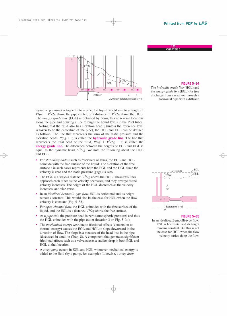
dynamic pressure) is tapped into a pipe, the liquid would rise to a height ofP/rg � V2/2g above the pipe center, or a distance of V2/2g above the HGL.The energy grade line (EGL) is obtained by doing this at several locationsalong the pipe and drawing a line through the liquid levels in the Pitot tubes.
Noting that the fluid also has elevation head z (unless the reference levelis taken to be the centerline of the pipe), the HGL and EGL can be definedas follows: The line that represents the sum of the static pressure and theelevation heads, P/rg � z, is called the hydraulic grade line. The line thatrepresents the total head of the fluid, P/rg � V2/2g � z, is called theenergy grade line. The difference between the heights of EGL and HGL isequal to the dynamic head, V2/2g. We note the following about the HGLand EGL:
• For stationary bodies such as reservoirs or lakes, the EGL and HGLcoincide with the free surface of the liquid. The elevation of the freesurface z in such cases represents both the EGL and the HGL since thevelocity is zero and the static pressure (gage) is zero.
• The EGL is always a distance V2/2g above the HGL. These two linesapproach each other as the velocity decreases, and they diverge as thevelocity increases. The height of the HGL decreases as the velocityincreases, and vice versa.
• In an idealized Bernoulli-type flow, EGL is horizontal and its heightremains constant. This would also be the case for HGL when the flowvelocity is constant (Fig. 5–35).
• For open-channel flow, the HGL coincides with the free surface of theliquid, and the EGL is a distance V2/2g above the free surface.
• At a pipe exit, the pressure head is zero (atmospheric pressure) and thusthe HGL coincides with the pipe outlet (location 3 on Fig. 5–34).
• The mechanical energy loss due to frictional effects (conversion tothermal energy) causes the EGL and HGL to slope downward in thedirection of flow. The slope is a measure of the head loss in the pipe(discussed in detail in Chap. 8). A component that generates significantfrictional effects such as a valve causes a sudden drop in both EGL andHGL at that location.
• A steep jump occurs in EGL and HGL whenever mechanical energy isadded to the fluid (by a pump, for example). Likewise, a steep drop
193CHAPTER 5
Diffuser
Arbitrary reference plane (z = 0)
HGL
EGL
1
/2g
z
0
2 3
1
/2g2
V2
V2
FIGURE 5–34
The hydraulic grade line (HGL) andthe energy grade line (EGL) for freedischarge from a reservoir through a
horizontal pipe with a diffuser.
Reference level0
(Horizontal)EGL
z
HGL
P–– g
2/2gV
r
FIGURE 5–35
In an idealized Bernoulli-type flow,EGL is horizontal and its heightremains constant. But this is not the case for HGL when the flow
velocity varies along the flow.
cen72367_ch05.qxd 10/29/04 2:25 PM Page 193

occurs in EGL and HGL whenever mechanical energy is removed fromthe fluid (by a turbine, for example), as shown in Fig. 5–36.
• The pressure (gage) of a fluid is zero at locations where the HGLintersects the fluid. The pressure in a flow section that lies above the HGLis negative, and the pressure in a section that lies below the HGL ispositive (Fig. 5–37). Therefore, an accurate drawing of a piping systemand the HGL can be used to determine the regions where the pressure inthe pipe is negative (below the atmospheric pressure).
The last remark enables us to avoid situations in which the pressure dropsbelow the vapor pressure of the liquid (which causes cavitation, as dis-cussed in Chap. 2). Proper consideration is necessary in the placement of aliquid pump to ensure that the suction side pressure does not fall too low,especially at elevated temperatures where vapor pressure is higher than it isat low temperatures.
Now we examine Fig. 5–34 more closely. At point 0 (at the liquid surface),EGL and HGL are even with the liquid surface since there is no flow there.HGL decreases rapidly as the liquid accelerates into the pipe; however, EGLdecreases very slowly through the well-rounded pipe inlet. EGL declines con-tinually along the flow direction due to friction and other irreversible losses inthe flow. EGL cannot increase in the flow direction unless energy is suppliedto the fluid. HGL can rise or fall in the flow direction, but can never exceedEGL. HGL rises in the diffuser section as the velocity decreases, and the sta-tic pressure recovers somewhat; the total pressure does not recover, however,and EGL decreases through the diffuser. The difference between EGL andHGL is V2
1/2g at point 1, and V22/2g at point 2. Since V1 � V2, the difference
between the two grade lines is larger at point 1 than at point 2. The downwardslope of both grade lines is larger for the smaller diameter section of pipesince the frictional head loss is greater. Finally, HGL decays to the liquid sur-face at the outlet since the pressure there is atmospheric. However, EGL isstill higher than HGL by the amount V2
2/2g since V3 � V2 at the outlet.
5–5 � APPLICATIONS OF THE BERNOULLI EQUATION
In Section 5–4, we discussed the fundamental aspects of the Bernoulli equa-tion. In this section, we demonstrate its use in a wide range of applicationsthrough examples.
EXAMPLE 5–5 Spraying Water into the Air
Water is flowing from a hose attached to a water main at 400 kPa gage (Fig.
5–38). A child places his thumb to cover most of the hose outlet, causing a
thin jet of high-speed water to emerge. If the hose is held upward, what is
the maximum height that the jet could achieve?
SOLUTION Water from a hose attached to the water main is sprayed into
the air. The maximum height the water jet can rise is to be determined.
Assumptions 1 The flow exiting into the air is steady, incompressible, and
irrotational (so that the Bernoulli equation is applicable). 2 The water pressure
194FLUID MECHANICS
PumpTurbine
EGL
HGL
Wpump Wturbine· ·
FIGURE 5–36
A steep jump occurs in EGL and HGLwhenever mechanical energy is addedto the fluid by a pump, and a steep drop
occurs whenever mechanical energy isremoved from the fluid by a turbine.
Negative P
P = 0
P = 0HGL
Positive P
Positive P
FIGURE 5–37
The pressure (gage) of a fluid is zeroat locations where the HGL intersects
the fluid, and the pressure is negative(vacuum) in a flow section that liesabove the HGL.
cen72367_ch05.qxd 10/29/04 2:25 PM Page 194

in the hose near the outlet is equal to the water main pressure. 3 The surface
tension effects are negligible. 4 The friction between the water and air is neg-
ligible. 5 The irreversibilities that may occur at the outlet of the hose due to
abrupt expansion are negligible.
Properties We take the density of water to be 1000 kg/m3.
Analysis This problem involves the conversion of flow, kinetic, and potential
energies to each other without involving any pumps, turbines, and wasteful
components with large frictional losses, and thus it is suitable for the use of
the Bernoulli equation. The water height will be maximum under the stated
assumptions. The velocity inside the hose is relatively low (V1 � 0) and we
take the hose outlet as the reference level (z1 � 0). At the top of the water
trajectory V2 � 0, and atmospheric pressure pertains. Then the Bernoulli
equation simplifies to
Solving for z2 and substituting,
Therefore, the water jet can rise as high as 40.8 m into the sky in this case.
Discussion The result obtained by the Bernoulli equation represents the
upper limit and should be interpreted accordingly. It tells us that the water
cannot possibly rise more than 40.8 m, and, in all likelihood, the rise will be
much less than 40.8 m due to irreversible losses that we neglected.
EXAMPLE 5–6 Water Discharge from a Large Tank
A large tank open to the atmosphere is filled with water to a height of 5 m
from the outlet tap (Fig. 5–39). A tap near the bottom of the tank is now
opened, and water flows out from the smooth and rounded outlet. Determine
the water velocity at the outlet.
SOLUTION A tap near the bottom of a tank is opened. The exit velocity of
water from the tank is to be determined.
Assumptions 1 The flow is incompressible and irrotational (except very close
to the walls). 2 The water drains slowly enough that the flow can be approxi-
mated as steady (actually quasi-steady when the tank begins to drain).
Analysis This problem involves the conversion of flow, kinetic, and potential
energies to each other without involving any pumps, turbines, and wasteful
components with large frictional losses, and thus it is suitable for the use of
the Bernoulli equation. We take point 1 to be at the free surface of water so
that P1 � Patm (open to the atmosphere), V1 � 0 (the tank is large relative to
the outlet), and z1 � 5 m and z2 � 0 (we take the reference level at the
center of the outlet). Also, P2 � Patm (water discharges into the atmosphere).
Then the Bernoulli equation simplifies to
P1
rg�
V 21
2g � z1 �
P2
rg�
V 22
2g� z2 → z1 �
V 22
2g
� 40.8 m
z2 �P1 � Patm
rg�
P1, gage
rg�
400 kPa
(1000 kg/m3)(9.81 m/s2) a1000 N/m2
1 kPab a1 kg � m/s2
1 Nb
P1
rg�
V 21
2g � z1 �
P2
rg�
V˛
22
2g � z2 →
P1
rg�
Patm
rg� z2
195CHAPTER 5
Water jet
2
Hose
0
z
1
FIGURE 5–38
Schematic for Example 5–5.
Water5 m
0
z
1
2
V2
FIGURE 5–39
Schematic for Example 5–6.
0 0 0Q Q
¡
0 0Q
¡
cen72367_ch05.qxd 10/29/04 2:25 PM Page 195

Solving for V2 and substituting,
The relation V � is called the Toricelli equation.
Therefore, the water leaves the tank with an initial velocity of 9.9 m/s.
This is the same velocity that would manifest if a solid were dropped a dis-
tance of 5 m in the absence of air friction drag. (What would the velocity be
if the tap were at the bottom of the tank instead of on the side?)
Discussion If the orifice were sharp-edged instead of rounded, then the flow
would be disturbed, and the velocity would be less than 9.9 m/s, especially
near the edges. Care must be exercised when attempting to apply the
Bernoulli equation to situations where abrupt expansions or contractions
occur since the friction and flow disturbance in such cases may not be neg-
ligible.
EXAMPLE 5–7 Siphoning Out Gasoline from a Fuel Tank
During a trip to the beach (Patm � 1 atm � 101.3 kPa), a car runs out of
gasoline, and it becomes necessary to siphon gas out of the car of a Good
Samaritan (Fig. 5–40). The siphon is a small-diameter hose, and to start the
siphon it is necessary to insert one siphon end in the full gas tank, fill the
hose with gasoline via suction, and then place the other end in a gas can
below the level of the gas tank. The difference in pressure between point 1
(at the free surface of the gasoline in the tank) and point 2 (at the outlet of
the tube) causes the liquid to flow from the higher to the lower elevation.
Point 2 is located 0.75 m below point 1 in this case, and point 3 is located
2 m above point 1. The siphon diameter is 4 mm, and frictional losses in
the siphon are to be disregarded. Determine (a) the minimum time to with-
draw 4 L of gasoline from the tank to the can and (b) the pressure at point
3. The density of gasoline is 750 kg/m3.
SOLUTION Gasoline is to be siphoned from a tank. The minimum time it
takes to withdraw 4 L of gasoline and the pressure at the highest point in
the system are to be determined.
Assumptions 1 The flow is steady and incompressible. 2 Even though the
Bernoulli equation is not valid through the pipe because of frictional losses,
we employ the Bernoulli equation anyway in order to obtain a best-case esti-
mate. 3 The change in the gasoline surface level inside the tank is negligible
compared to elevations z1 and z2 during the siphoning period.
Properties The density of gasoline is given to be 750 kg/m3.
Analysis (a) We take point 1 to be at the free surface of gasoline in the
tank so that P1 � Patm (open to the atmosphere), V1 � 0 (the tank is large
relative to the tube diameter), and z2 � 0 (point 2 is taken as the reference
level). Also, P2 � Patm (gasoline discharges into the atmosphere). Then the
Bernoulli equation simplifies to
Solving for V2 and substituting,
V2 � 22gz1 � 22(9.81 m/s2)(0.75 m) � 3.84 m/s
P1
rg�
V 21
2g � z1 �
P2
rg�
V 22
2g� z2 → z1 �
V 22
2g
12gz
V2 � 22gz1 � 22(9.81 m/s2)(5 m) � 9.9 m/s
196FLUID MECHANICS
0 0Q
¡
0
z
z3
z1
z2
Gastank
0.75 m
2 m
Gasoline
siphoning
tube
Gas can
1
2
3
FIGURE 5–40
Schematic for Example 5–7.
cen72367_ch05.qxd 10/29/04 2:25 PM Page 196

The cross-sectional area of the tube and the flow rate of gasoline are
Then the time needed to siphon 4 L of gasoline becomes
(b) The pressure at point 3 can be determined by writing the Bernoulli equa-
tion between points 2 and 3. Noting that V2 � V3 (conservation of mass), z2
� 0, and P2 � Patm,
Solving for P3 and substituting,
Discussion The siphoning time is determined by neglecting frictional
effects, and thus this is the minimum time required. In reality, the time will
be longer than 53.1 s because of friction between the gasoline and the tube
surface. Also, the pressure at point 3 is below the atmospheric pressure. If
the elevation difference between points 1 and 3 is too high, the pressure at
point 3 may drop below the vapor pressure of gasoline at the gasoline tem-
perature, and some gasoline may evaporate (cavitate). The vapor then may
form a pocket at the top and halt the flow of gasoline.
EXAMPLE 5–8 Velocity Measurement by a Pitot Tube
A piezometer and a Pitot tube are tapped into a horizontal water pipe, as
shown in Fig. 5–41, to measure static and stagnation (static � dynamic)
pressures. For the indicated water column heights, determine the velocity at
the center of the pipe.
SOLUTION The static and stagnation pressures in a horizontal pipe are
measured. The velocity at the center of the pipe is to be determined.
Assumptions 1 The flow is steady and incompressible. 2 Points 1 and 2 are
close enough together that the irreversible energy loss between these two
points is negligible, and thus we can use the Bernoulli equation.
Analysis We take points 1 and 2 along the centerline of the pipe, with point
1 directly under the piezometer and point 2 at the tip of the Pitot tube. This
is a steady flow with straight and parallel streamlines, and the gage pres-
sures at points 1 and 2 can be expressed as
P2 � rg(h1 � h2 � h3)
P1 � rg(h1 � h2)
� 81.1 kPa
� 101.3 kPa � (750 kg/m3)(9.81 m/s2)(2.75 m)a 1 N
1 kg � m/s2b a 1 kPa
1000 N/m2b
P3 � Patm � rgz3
P2
rg�
V 22
2g� z2 �
P3
rg�
V 23
2g� z3 → Patm
rg�
P3
rg� z3
�t �V
V# �
4 L
0.0753 L/s� 53.1 s
V#
� V2 A � (3.84 m/s)(1.96 � 10�5 m2) � 7.53 � 10�5 m3/s � 0.0753 L/s
A � pD2/4 � p(5 � 10�3 m)2/4 � 1.96 � 10�5 m2
197CHAPTER 5
¡
0
h3 = 12 cm
h2 = 7 cm
h1 = 3 cm
Stagnation
point
Water1 2
V1
FIGURE 5–41
Schematic for Example 5–8.
cen72367_ch05.qxd 10/29/04 2:25 PM Page 197

Noting that point 2 is a stagnation point and thus V2 � 0 and z1 � z2, the
application of the Bernoulli equation between points 1 and 2 gives
Substituting the P1 and P2 expressions gives
Solving for V1 and substituting,
Discussion Note that to determine the flow velocity, all we need is to mea-
sure the height of the excess fluid column in the Pitot tube.
EXAMPLE 5–9 The Rise of the Ocean Due to a Hurricane
A hurricane is a tropical storm formed over the ocean by low atmospheric
pressures. As a hurricane approaches land, inordinate ocean swells (very
high tides) accompany the hurricane. A Class-5 hurricane features winds in
excess of 155 mph, although the wind velocity at the center “eye” is very
low.
Figure 5–42 depicts a hurricane hovering over the ocean swell below. The
atmospheric pressure 200 mi from the eye is 30.0 in Hg (at point 1, gener-
ally normal for the ocean) and the winds are calm. The hurricane atmo-
spheric pressure at the eye of the storm is 22.0 in Hg. Estimate the ocean
swell at (a) the eye of the hurricane at point 3 and (b) point 2, where the
wind velocity is 155 mph. Take the density of seawater and mercury to be
64 lbm/ft3 and 848 lbm/ft3, respectively, and the density of air at normal
sea-level temperature and pressure to be 0.076 lbm/ft3.
SOLUTION A hurricane is moving over the ocean. The amount of ocean
swell at the eye and at active regions of the hurricane are to be determined.
Assumptions 1 The airflow within the hurricane is steady, incompressible,
and irrotational (so that the Bernoulli equation is applicable). (This is cer-
tainly a very questionable assumption for a highly turbulent flow, but it is jus-
tified in the solution.) 2 The effect of water drifted into the air is negligible.
Properties The densities of air at normal conditions, seawater, and mercury
are given to be 0.076 lbm/ft3, 64 lbm/ft3, and 848 lbm/ft3, respectively.
Analysis (a) Reduced atmospheric pressure over the water causes the water
to rise. Thus, decreased pressure at point 2 relative to point 1 causes the
ocean water to rise at point 2. The same is true at point 3, where the storm air
velocity is negligible. The pressure difference given in terms of the mercury
column height can be expressed in terms of the seawater column height by
�P � (rgh)Hg � (rgh)sw → hsw �rHg
rsw
hHg
V1 � 22gh3 � 22(9.81 m/s2)(0.12 m) � 1.53 m/s
V 21
2g�
P2 � P1
rg�rg(h1 � h2 � h3) � rg(h1 � h2)
rg� h3
P1
rg�
V 21
2g� z1 �
P2
rg�
V 22
2g � z2 →
V 21
2g�
P2 � P1
rg
198FLUID MECHANICS
0Q
Calm
ocean
level
Ocean
HurricaneEye
1
23
h1h2
A B
FIGURE 5–42
Schematic for Example 5–9. Thevertical scale is greatly exaggerated.
cen72367_ch05.qxd 10/29/04 2:25 PM Page 198

Then the pressure difference between points 1 and 3 in terms of the seawa-
ter column height becomes
which is equivalent to the storm surge at the eye of the hurricane since the
wind velocity there is negligible and there are no dynamic effects.
(b) To determine the additional rise of ocean water at point 2 due to the high
winds at that point, we write the Bernoulli equation between points A and B,
which are on top of the points 2 and 3, respectively. Noting that VB � 0 (the
eye region of the hurricane is relatively calm) and zA � zB (both points are
on the same horizontal line), the Bernoulli equation simplifies to
Substituting,
where r is the density of air in the hurricane. Noting that the density of an
ideal gas at constant temperature is proportional to absolute pressure and
the density of air at the normal atmospheric pressure of 14.7 psia � 30 in
Hg is 0.076 lbm/ft3, the density of air in the hurricane is
Using the relation developed above in part (a), the seawater column height
equivalent to 803 ft of air column height is determined to be
Therefore, the pressure at point 2 is 0.70 ft seawater column lower than the
pressure at point 3 due to the high wind velocities, causing the ocean to rise
an additional 0.70 ft. Then the total storm surge at point 2 becomes
h2 � h1 � hdynamic � 8.83 � 0.70 � 9.53 ft
Discussion This problem involves highly turbulent flow and the intense
breakdown of the streamlines, and thus the applicability of the Bernoulli
equation in part (b) is questionable. Furthermore, the flow in the eye of the
storm is not irrotational, and the Bernoulli equation constant changes across
streamlines (see Chap. 10). The Bernoulli analysis can be thought of as the
limiting, ideal case, and shows that the rise of seawater due to high-velocity
winds cannot be more than 0.70 ft.
The wind power of hurricanes is not the only cause of damage to coastal
areas. Ocean flooding and erosion from excessive tides is just as serious, as
are high waves generated by the storm turbulence and energy.
hdynamic �rair
rsw
hair � a0.056 lbm/ft3
64 lbm/ft3b (803 ft) � 0.70 ft
rair �Pair
Patm air
ratm air � a22 in Hg
30 in Hgb (0.076 lbm/ft3) � 0.056 lbm/ft3
PB � PA
rg�
V 2A
2g�
(155 mph)2
2(32.2 ft/s2) a1.4667 ft/s
1 mphb 2
� 803 ft
PA
rg�
V 2A
2g� zA �
PB
rg�
V 2B
2g � zB →
PB � PA
rg�
V 2A
2g
h1 �rHg
rsw
hHg � a848 lbm/ft3
64 lbm/ft3b3(30 � 22) in Hg4a 1 ft
12 inb � 8.83 ft
199CHAPTER 5
0Q
cen72367_ch05.qxd 10/29/04 2:25 PM Page 199

EXAMPLE 5–10 Bernoulli Equation for Compressible Flow
Derive the Bernoulli equation when the compressibility effects are not negli-
gible for an ideal gas undergoing (a) an isothermal process and (b) an isen-
tropic process.
SOLUTION The Bernoulli equation for compressible flow is to be obtained
for an ideal gas for isothermal and isentropic processes.
Assumptions 1 The flow is steady and frictional effects are negligible. 2 The
fluid is an ideal gas, so the relation P � rRT is applicable. 3 The specific
heats are constant so that P/rk � constant during an isentropic process.
Analysis (a) When the compressibility effects are significant and the flow
cannot be assumed to be incompressible, the Bernoulli equation is given by
Eq. 5–40 as
(1)
The compressibility effects can be properly accounted for by expressing r in
terms of pressure, and then performing the integration � dP/r in Eq. 1. But
this requires a relation between P and r for the process. For the isothermal
expansion or compression of an ideal gas, the integral in Eq. 1 can be per-
formed easily by noting that T � constant and substituting r � P/RT. It
gives
Substituting into Eq. 1 gives the desired relation,
Isothermal process: (2)
(b) A more practical case of compressible flow is the isentropic flow of ideal
gases through equipment that involves high-speed fluid flow such as nozzles,
diffusers, and the passages between turbine blades. Isentropic (i.e.,
reversible and adiabatic) flow is closely approximated by these devices, and
it is characterized by the relation P/rk � C � constant, where k is the spe-
cific heat ratio of the gas. Solving for r from P/rk � C gives r � C �1/kP1/k.
Performing the integration,
(3)
Substituting, the Bernoulli equation for steady, isentropic, compressible flow
of an ideal gas becomes
Isentropic flow: (4a)
or
(4b)
A common practical situation involves the acceleration of a gas from rest
(stagnation conditions at state 1) with negligible change in elevation. In
that case we have z1 � z2 and V1 � 0. Noting that r � P/RT for ideal
a k
k � 1bP1
r1�
V 21
2� gz1 � a k
k � 1bP2
r2�
V 22
2� gz2
a k
k � 1bPR
�V 2
2� gz � constant
� dP
r� � C 1/kP �1/k dP � C 1/k
P�1/k�1
�1/k � 1�
P 1/k
r
P�1/k�1
�1/k � 1� a k
k � 1bPr
RT ln P �V 2
2� gz � constant
� dP
r� �
dP
P/RT� RT ln P
� dP
r�
V 2
2� gz � constant (along a streamline)
200FLUID MECHANICS
cen72367_ch05.qxd 10/29/04 2:25 PM Page 200

gases, P/rk � constant for isentropic flow, and the Mach number is defined
as Ma � V/c where is the local speed of sound for ideal gases,
Eq. 4b simplifies to
(4c)
where state 1 is the stagnation state and state 2 is any state along the flow.
Discussion It can be shown that the results obtained using the compress-
ible and incompressible equations deviate no more than 2 percent when the
Mach number is less than 0.3. Therefore, the flow of an ideal gas can be
considered to be incompressible when Ma � 0.3. For atmospheric air at
normal conditions, this corresponds to a flow speed of about 100 m/s or
360 km/h, which covers our range of interest.
5–6 � GENERAL ENERGY EQUATION
One of the most fundamental laws in nature is the first law of thermody-
namics, also known as the conservation of energy principle, which pro-vides a sound basis for studying the relationships among the various formsof energy and energy interactions. It states that energy can be neither cre-
ated nor destroyed during a process; it can only change forms. Therefore,every bit of energy must be accounted for during a process.
A rock falling off a cliff, for example, picks up speed as a result of itspotential energy being converted to kinetic energy (Fig. 5–43). Experimen-tal data show that the decrease in potential energy equals the increase inkinetic energy when the air resistance is negligible, thus confirming the con-servation of energy principle. The conservation of energy principle alsoforms the backbone of the diet industry: a person who has a greater energyinput (food) than energy output (exercise) will gain weight (store energy inthe form of fat), and a person who has a smaller energy input than outputwill lose weight. The change in the energy content of a system is equal tothe difference between the energy input and the energy output, and the conservation of energy principle for any system can be expressed simply asEin � Eout � �E.
The transfer of any quantity (such as mass, momentum, and energy) isrecognized at the boundary as the quantity crosses the boundary. A quantityis said to enter a system if it crosses the boundary from the outside to theinside, and to exit the system if it moves in the reverse direction. A quantitythat moves from one location to another within a system is not consideredas a transferred quantity in an analysis since it does not enter or exit the sys-tem. Therefore, it is important to specify the system and thus clearly iden-tify its boundaries before an engineering analysis is performed.
The energy content of a fixed quantity of mass (a closed system) can bechanged by two mechanisms: heat transfer Q and work transfer W. Then theconservation of energy for a fixed quantity of mass can be expressed in rateform as (Fig. 5–44)
(5–49)Q#
net in � W#
net in �dE sys
dt or Q
#
net in � W#
net in �d
dt �
sys
re dV
P1
P2� c1 � ak � 1
2b Ma 2
2dk /(k�1)
c � 1kRT
201CHAPTER 5
PE1 = 10 kJm
KE1 = 0
PE2 = 7 kJm
KE2 = 3 kJ
∆ z
FIGURE 5–43
Energy cannot be created or destroyed during a process;
it can only change forms.
Wshaft, in = 6 kJ
= 18 kJ
Qout
= 3 kJ
Qin
= 15 kJ
∆E = (15 – 3) + 6
FIGURE 5–44
The energy change of a system during a process is equal to the net
work and heat transfer between thesystem and its surroundings.
cen72367_ch05.qxd 10/29/04 2:25 PM Page 201

where Q·
net in � Q·
in � Q·
out is the net rate of heat transfer to the system (neg-ative, if from the system), W
·net in � W
·in � W
·out is the net power input to the
system in all forms (negative, if power output) and dEsys/dt is the rate ofchange of the total energy content of the system. The overdot stands fortime rate. For simple compressible systems, total energy consists of internal,kinetic, and potential energies, and it is expressed on a unit-mass basis as(see Chap. 2)
(5–50)
Note that total energy is a property, and its value does not change unless thestate of the system changes.
Energy Transfer by Heat, QIn daily life, we frequently refer to the sensible and latent forms of internalenergy as heat, and talk about the heat content of bodies. Scientifically themore correct name for these forms of energy is thermal energy. For single-phase substances, a change in the thermal energy of a given mass results ina change in temperature, and thus temperature is a good representative ofthermal energy. Thermal energy tends to move naturally in the direction ofdecreasing temperature, and the transfer of thermal energy from one systemto another as a result of a temperature difference is called heat transfer.
Therefore, an energy interaction is heat transfer only if it takes placebecause of a temperature difference. The warming up of a canned drink in awarmer room, for example, is due to heat transfer (Fig. 5–45). The time rateof heat transfer is called heat transfer rate and is denoted by Q
..
The direction of heat transfer is always from the higher-temperature bodyto the lower-temperature one. Once temperature equality is established, heattransfer stops. There cannot be any heat transfer between two systems (or asystem and its surroundings) that are at the same temperature.
A process during which there is no heat transfer is called an adiabatic
process. There are two ways a process can be adiabatic: Either the system iswell insulated so that only a negligible amount of heat can pass through thesystem boundary, or both the system and the surroundings are at the sametemperature and therefore there is no driving force (temperature difference)for heat transfer. An adiabatic process should not be confused with anisothermal process. Even though there is no heat transfer during an adia-batic process, the energy content and thus the temperature of a system canstill be changed by other means such as work transfer.
Energy Transfer by Work, WAn energy interaction is work if it is associated with a force acting througha distance. A rising piston, a rotating shaft, and an electric wire crossing thesystem boundary are all associated with work interactions. The time rate ofdoing work is called power and is denoted by W
.. Car engines and hydraulic,
steam, and gas turbines produce work; compressors, pumps, fans, and mix-ers consume work.
Work-consuming devices transfer energy to the fluid, and thus increasethe energy of the fluid. A fan in a room, for example, mobilizes the air andincreases its kinetic energy. The electric energy a fan consumes is first con-verted to mechanical energy by its motor that forces the shaft of the blades
e � u � ke � pe � u �V 2
2� gz
202FLUID MECHANICS
Room air25°C
No heattransfer Heat Heat
25°C 5°C
8 J/s 16 J/s
15°C
FIGURE 5–45
Temperature difference is the drivingforce for heat transfer. The larger thetemperature difference, the higher isthe rate of heat transfer.
cen72367_ch05.qxd 10/29/04 2:25 PM Page 202

to rotate. This mechanical energy is then transferred to the air, as evidencedby the increase in air velocity. This energy transfer to air has nothing to dowith a temperature difference, so it cannot be heat transfer. Therefore, itmust be work. Air discharged by the fan eventually comes to a stop and thusloses its mechanical energy as a result of friction between air particles ofdifferent velocities. But this is not a “loss” in the real sense; it is simply theconversion of mechanical energy to an equivalent amount of thermal energy(which is of limited value, and thus the term loss) in accordance with theconservation of energy principle. If a fan runs a long time in a sealed room,we can sense the buildup of this thermal energy by a rise in air temperature.
A system may involve numerous forms of work, and the total work can beexpressed as
(5–51)
where Wshaft is the work transmitted by a rotating shaft, Wpressure is the workdone by the pressure forces on the control surface, Wviscous is the work doneby the normal and shear components of viscous forces on the control sur-face, and Wother is the work done by other forces such as electric, magnetic,and surface tension, which are insignificant for simple compressible systemsand are not considered in this text. We do not consider Wviscous either since itis usually small relative to other terms in control volume analysis. But itshould be kept in mind that the work done by shear forces as the bladesshear through the fluid may need to be considered in a refined analysis ofturbomachinery.
Shaft WorkMany flow systems involve a machine such as a pump, a turbine, a fan, or acompressor whose shaft protrudes through the control surface, and the worktransfer associated with all such devices is simply referred to as shaft work
Wshaft. The power transmitted via a rotating shaft is proportional to the shafttorque Tshaft and is expressed as
(5–52)
where v is the angular speed of the shaft in rad/s and n.
is defined as thenumber of revolutions of the shaft per unit time, often expressed in rev/minor rpm.
Work Done by Pressure ForcesConsider a gas being compressed in the piston-cylinder device shown inFig. 5–46a. When the piston moves down a differential distance ds underthe influence of the pressure force PA, where A is the cross-sectional area ofthe piston, the boundary work done on the system is dWboundary � PA ds.Dividing both sides of this relation by the differential time interval dt givesthe time rate of boundary work (i.e., power),
where Vpiston � ds/dt is the piston velocity, which is the velocity of the mov-ing boundary at the piston face.
Now consider a material chunk of fluid (a system) of arbitrary shape,which moves with the flow and is free to deform under the influence ofpressure, as shown in Fig. 5–46b. Pressure always acts inward and normal
dW#pressure � dW
#boundary � PAVpiston
W#
shaft � vTshaft � 2pn#Tshaft
Wtotal � Wshaft � Wpressure � Wviscous � Wother
203CHAPTER 5
System
System boundary, A
dV
dm
dA
Pn
u
→V
→
(b)
(a)
ds
P
A
Vpiston
System
(gas in cylinder)
FIGURE 5–46
The pressure force acting on (a) themoving boundary of a system in
a piston-cylinder device, and (b) the differential surface area of a system of arbitrary shape.
cen72367_ch05.qxd 10/29/04 2:25 PM Page 203

to the surface, and the pressure force acting on a differential area dA isP dA. Again noting that work is force times distance and distance traveledper unit time is velocity, the time rate at which work is done by pressureforces on this differential part of the system is
(5–53)
since the normal component of velocity through the differential area dA isVn � V cos u � V
→· n
→. Note that n
→is the outer normal of dA, and thus the
quantity V→
· n→
is positive for expansion and negative for compression. Thenegative sign in Eq. 5–53 ensures that work done by pressure forces is posi-tive when it is done on the system, and negative when it is done by the sys-tem, which agrees with our sign convention. The total rate of work done bypressure forces is obtained by integrating dW
.pressure over the entire surface A,
(5–54)
In light of these discussions, the net power transfer can be expressed as
(5–55)
Then the rate form of the conservation of energy relation for a closed sys-tem becomes
(5–56)
To obtain a relation for the conservation of energy for a control volume,
we apply the Reynolds transport theorem by replacing B with total energyE, and b with total energy per unit mass e, which is e � u � ke � pe � u
� V2/2 � gz (Fig. 5–47). This yields
(5–57)
Substituting the left-hand side of Eq. 5–56 into Eq. 5–57, the general formof the energy equation that applies to fixed, moving, or deforming controlvolumes becomes
(5–58)
which can be stated as
Here V→
r � V→
� V→
CS is the fluid velocity relative to the control surface, andthe product r(V
→
r · n→) dA represents the mass flow rate through area element
dA into or out of the control volume. Again noting that n→
is the outer normalof dA, the quantity V
→
r · n→
and thus mass flow is positive for outflow andnegative for inflow.
§The net rate of energy
transfer into a CV by
heat and work transfer
¥ � § The time rate of
change of the energy
content of the CV
¥ � § The net flow rate of
energy out of the control
surface by mass flow
¥
Q#
net in � W#
shaft, net in � W#
pressure, net in �d
dt �
CV
er dV � �CS
er(V→
r � n→) dA
dE sys
dt�
d
dt �
CV
er dV � �CS
er(V→
r � n→)A
Q#
net in � W#
shaft, net in � W#
pressure, net in �dE sys
dt
W#
net in � W#
shaft, net in � W#
pressure, net in � W#
shaft, net in � �A
P(V→
� n→) dA
W#
pressure, net in � � �A
P(V→
� n→) dA � � �
A
P
r r(V
→
� n→) dA
dW#
pressure � �P dA Vn � �P dA(V→
� n→)
204FLUID MECHANICS
= +br dV
B = E b = e b = e
dBsys
dtV
d
dtCV
� br( r · n ) dA
CS
�
= +er dV
dEsys
dtV
d
dtCV
� er( r · n ) dA
CS
�
→
→→
FIGURE 5–47
The conservation of energy equation is obtained by replacing B in theReynolds transport theorem by energy E and b by e.
cen72367_ch05.qxd 10/29/04 2:25 PM Page 204

Substituting the surface integral for the rate of pressure work from Eq. 5–54into Eq. 5–58 and combining it with the surface integral on the right give
(5–59)
This is a very convenient form for the energy equation since pressure workis now combined with the energy of the fluid crossing the control surfaceand we no longer have to deal with pressure work.
The term P/r � Pv � wflow is the flow work, which is the work associ-ated with pushing a fluid into or out of a control volume per unit mass. Notethat the fluid velocity at a solid surface is equal to the velocity of the solidsurface because of the no-slip condition and is zero for nonmoving surfaces.As a result, the pressure work along the portions of the control surface thatcoincide with nonmoving solid surfaces is zero. Therefore, pressure workfor fixed control volumes can exist only along the imaginary part of thecontrol surface where the fluid enters and leaves the control volume, i.e.,inlets and outlets.
For a fixed control volume (no motion or deformation of control volume),V→
r � V→
and the energy equation Eq. 5–59 becomes
Fixed CV: (5–60)
This equation is not in a convenient form for solving practical engineeringproblems because of the integrals, and thus it is desirable to rewrite it interms of average velocities and mass flow rates through inlets and outlets. IfP/r � e is nearly uniform across an inlet or outlet, we can simply take it
outside the integral. Noting that is the mass flow rate
across an inlet or outlet, the rate of inflow or outflow of energy through theinlet or outlet can be approximated as m
.(P/r � e). Then the energy equa-
tion becomes (Fig. 5–48)
(5–61)
where e � u � V2/2 � gz (Eq. 5–50) is the total energy per unit mass forboth the control volume and flow streams. Then,
Q#
net in � W#
shaft, net in �d
dt �
CV
er dV � aout
m# aPr
� eb � ain
m# aPr
� eb
m#
� �Ac
r(V→
� n→) dAc
Q#
net in � W#
shaft, net in �d
dt �
CV
er dV � �CS
aPr
� ebr(V→ � n→) dA
Q#
net in � W#
shaft, net in �d
dt �
CV
er dV � �CS
aPr
� ebr(V→r � n→) dA
205CHAPTER 5
Wshaft, net in
mout ,
energyout
energyout
⋅min ,
energyin
⋅
min ,
energyin
⋅
mout ,⋅
energyout
mout ,⋅
⋅
Qnet in⋅
In
In
Out
Out
Out
Fixedcontrolvolume
FIGURE 5–48
In a typical engineering problem, thecontrol volume may contain many
inlets and outlets; energy flows in ateach inlet, and energy flows out ateach outlet. Energy also enters the
control volume through net heattransfer and net shaft work.
(5–62)
or
(5–63)
Q#
net in � W#
shaft, net in �d
dt �
CV
er dV � aout
m# ah �
V 2
2� gzb � a
in
m# ah �
V 2
2� gzb
Q#
net in � W#
shaft, net in �d
dt �
CV
er dV � aout
m# aPr
� u �V 2
2� gzb � a
in
m# aPr
� u �V2
2� gzb
where we used the definition of enthalpy h � u � Pv � u � P/r. The lasttwo equations are fairly general expressions of conservation of energy, buttheir use is still limited to fixed control volumes, uniform flow at inlets and
cen72367_ch05.qxd 10/29/04 2:25 PM Page 205
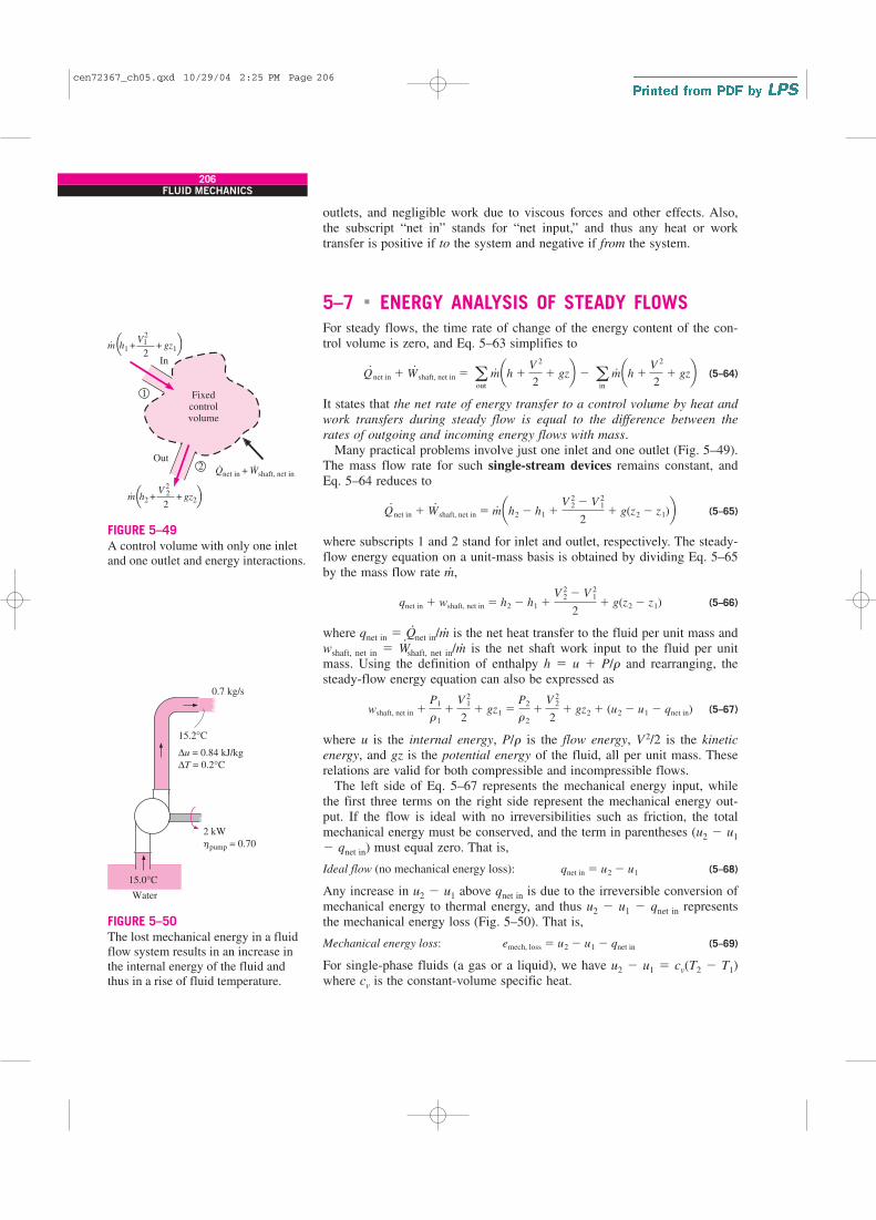
outlets, and negligible work due to viscous forces and other effects. Also,the subscript “net in” stands for “net input,” and thus any heat or worktransfer is positive if to the system and negative if from the system.
5–7 � ENERGY ANALYSIS OF STEADY FLOWS
For steady flows, the time rate of change of the energy content of the con-trol volume is zero, and Eq. 5–63 simplifies to
(5–64)
It states that the net rate of energy transfer to a control volume by heat and
work transfers during steady flow is equal to the difference between the
rates of outgoing and incoming energy flows with mass.Many practical problems involve just one inlet and one outlet (Fig. 5–49).
The mass flow rate for such single-stream devices remains constant, andEq. 5–64 reduces to
(5–65)
where subscripts 1 and 2 stand for inlet and outlet, respectively. The steady-flow energy equation on a unit-mass basis is obtained by dividing Eq. 5–65by the mass flow rate m
.,
(5–66)
where qnet in � Q.net in/m
.is the net heat transfer to the fluid per unit mass and
wshaft, net in � W.shaft, net in/m
.is the net shaft work input to the fluid per unit
mass. Using the definition of enthalpy h � u � P/r and rearranging, thesteady-flow energy equation can also be expressed as
(5–67)
where u is the internal energy, P/r is the flow energy, V2/2 is the kinetic
energy, and gz is the potential energy of the fluid, all per unit mass. Theserelations are valid for both compressible and incompressible flows.
The left side of Eq. 5–67 represents the mechanical energy input, whilethe first three terms on the right side represent the mechanical energy out-put. If the flow is ideal with no irreversibilities such as friction, the totalmechanical energy must be conserved, and the term in parentheses (u2 � u1
� qnet in) must equal zero. That is,
Ideal flow (no mechanical energy loss): (5–68)
Any increase in u2 � u1 above qnet in is due to the irreversible conversion ofmechanical energy to thermal energy, and thus u2 � u1 � qnet in representsthe mechanical energy loss (Fig. 5–50). That is,
Mechanical energy loss: (5–69)
For single-phase fluids (a gas or a liquid), we have u2 � u1 � cv(T2 � T1)where cv is the constant-volume specific heat.
emech, loss � u2 � u1 � qnet in
qnet in � u2 � u1
wshaft, net in �P1
r1
�V 2
1
2� gz1 �
P2
r2
�V 2
2
2� gz2 � (u2 � u1 � qnet in)
qnet in � wshaft, net in � h2 � h1 �V 2
2 � V 21
2� g(z2 � z1)
Q#
net in � W#
shaft, net in � m# ah2 � h1 �
V 22 � V 2
1
2� g(z2 � z1)b
Q#
net in � W#
shaft, net in � aout
m# ah �
V 2
2� gzb � a
in
m# ah �
V 2
2� gzb
206FLUID MECHANICS
+ + h1
Qnet in + Wshaft, net in
gz121m⋅
⋅ ⋅
2V
In
Out
Fixedcontrolvolume
2
1
+ + h2 gz222m⋅2
V
Q Q
Q Q
FIGURE 5–49
A control volume with only one inletand one outlet and energy interactions.
15.2°C
15.0°C
Water
0.7 kg/s
∆u = 0.84 kJ/kg
∆T = 0.2°C
2 kW
pump = 0.70h
FIGURE 5–50
The lost mechanical energy in a fluidflow system results in an increase inthe internal energy of the fluid andthus in a rise of fluid temperature.
cen72367_ch05.qxd 10/29/04 2:25 PM Page 206

The steady-flow energy equation on a unit-mass basis can be written con-veniently as a mechanical energy balance as
(5–70)
or
(5–71)
Noting that wshaft, net in � wshaft, in � wshaft, out � wpump � wturbine, the mechan-ical energy balance can be written more explicitly as
(5–72)
where wpump is the mechanical work input (due to the presence of a pump,fan, compressor, etc.) and wturbine is the mechanical work output. When theflow is incompressible, either absolute or gage pressure can be used for P
since Patm/r would appear on both sides and would cancel out.Multiplying Eq. 5–72 by the mass flow rate m
.gives
(5–73)
where W.pump is the shaft power input through the pump’s shaft, W
.turbine is the
shaft power output through the turbine’s shaft, and E.mech, loss is the total
mechanical power loss, which consists of pump and turbine losses as well asthe frictional losses in the piping network. That is,
E.mech, loss � E
.mech loss, pump � E
.mech loss, turbine � E
.mech loss, piping
By convention, irreversible pump and turbine losses are treated separatelyfrom irreversible losses due to other components of the piping system. Thusthe energy equation can be expressed in its most common form in terms ofheads as (Fig. 5–51).
(5–74)
where is the useful head deliv-
ered to the fluid by the pump. Because of irreversible losses in the pump,hpump, u is less than W
.pump/m
.g by the factor hpump. Similarly,
is the extracted head removed
from the fluid by the turbine. Because of irreversible losses in the turbine,hturbine, e is greater than W
.turbine/m
.g by the factor hturbine. Finally,
is the irreversible head loss between
1 and 2 due to all components of the piping system other than the pump orturbine. Note that the head loss hL represents the frictional losses associatedwith fluid flow in piping, and it does not include the losses that occur withinthe pump or turbine due to the inefficiencies of these devices—these lossesare taken into account by hpump and hturbine. Equation 5–74 is illustratedschematically in Fig. 5–51.
hL �emech loss, piping
g�
E#
mech loss, piping
m#g
hturbine, e �wturbine, e
g�
W#
turbine, e
m#g
�W#
turbine
hturbinem#g
hpump, u �wpump, u
g�
W#
pump, u
m#g
�hpumpW
#
pump
m#g
P1
r1g�
V 21
2g� z1 � hpump, u �
P2
r2g�
V 22
2g� z2 � hturbine, e � hL
m# aP1
r1
�V 2
1
2� gz1b � W
#
pump � m# aP2
r2
�V 2
2
2� gz2b � W
#
turbine � E#
mech, loss
P1
r1
�V 2
1
2� gz1 � wpump �
P2
r2
�V 2
2
2� gz2 � wturbine � emech, loss
wshaft, net in �P1
r1
�V 2
1
2� gz1 �
P2
r2
�V 2
2
2� gz2 � emech, loss
emech, in � emech, out � emech, loss
207CHAPTER 5
cen72367_ch05.qxd 10/29/04 2:25 PM Page 207

The pump head is zero if the piping system does not involve a pump, afan, or a compressor, and the turbine head is zero if the system does notinvolve a turbine. Also, the head loss hL can sometimes be ignored when thefrictional losses in the piping system are negligibly small compared to theother terms in Eq. 5–74.
Special Case: Incompressible Flow with No
Mechanical Work Devices and Negligible FrictionWhen piping losses are negligible, there is negligible dissipation of mechan-ical energy into thermal energy, and thus hL � emech loss, piping /g ≅ 0, as shownlater in Example 5–11. Also, hpump, u � hturbine, e � 0 when there are nomechanical work devices such as fans, pumps, or turbines. Then Eq. 5–74reduces to
(5–75)
which is the Bernoulli equation derived earlier using Newton’s second lawof motion.
Kinetic Energy Correction Factor, AThe average flow velocity Vavg was defined such that the relation rVavgA givesthe actual mass flow rate. Therefore, there is no such thing as a correction fac-tor for mass flow rate. However, as Gaspard Coriolis (1792–1843) showed,the kinetic energy of a fluid stream obtained from V2/2 is not the same as theactual kinetic energy of the fluid stream since the square of a sum is not equalto the sum of the squares of its components (Fig. 5–52). This error can be cor-rected by replacing the kinetic energy terms V2/2 in the energy equation byaV avg
2 /2, where a is the kinetic energy correction factor. By using equationsfor the variation of velocity with the radial distance, it can be shown that thecorrection factor is 2.0 for fully developed laminar pipe flow, and it rangesbetween 1.04 and 1.11 for fully developed turbulent flow in a round pipe.
The kinetic energy correction factors are often ignored (i.e., a is set equalto 1) in an elementary analysis since (1) most flows encountered in practiceare turbulent, for which the correction factor is near unity, and (2) the
P1
rg�
V 21
2g� z1 �
P2
rg�
V 22
2g� z2 or P
rg�
V 2
2g� z � constant
208FLUID MECHANICS
Control volume
Emech loss, pump·
Wpump, u·
Wpump·
hpump, u
hturbine, e
Emech fluid, out·
Wturbine, e·
Wturbine·
Emech loss, turbine
·
hL
P1 z1
rg+ +
2g rg
P2 z2 + +
2g
Emech loss, piping·
2V2 1
V2 Emech fluid, in·
FIGURE 5–51
Mechanical energy flow chart for a fluid flow system that involves a pump and a turbine. Verticaldimensions show each energy termexpressed as an equivalent columnheight of fluid, i.e., head,
corresponding to each term of Eq. 5–74.
cen72367_ch05.qxd 10/29/04 2:25 PM Page 208
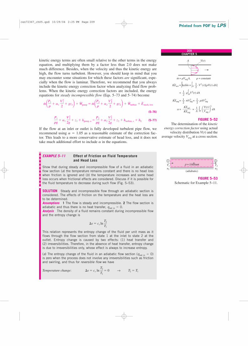
kinetic energy terms are often small relative to the other terms in the energyequation, and multiplying them by a factor less than 2.0 does not makemuch difference. Besides, when the velocity and thus the kinetic energy arehigh, the flow turns turbulent. However, you should keep in mind that youmay encounter some situations for which these factors are significant, espe-cially when the flow is laminar. Therefore, we recommend that you alwaysinclude the kinetic energy correction factor when analyzing fluid flow prob-lems. When the kinetic energy correction factors are included, the energyequations for steady incompressible flow (Eqs. 5–73 and 5–74) become
(5–76)
(5–77)
If the flow at an inlet or outlet is fully developed turbulent pipe flow, werecommend using a � 1.05 as a reasonable estimate of the correction fac-tor. This leads to a more conservative estimate of head loss, and it does nottake much additional effort to include a in the equations.
EXAMPLE 5–11 Effect of Friction on Fluid Temperature
and Head Loss
Show that during steady and incompressible flow of a fluid in an adiabatic
flow section (a) the temperature remains constant and there is no head loss
when friction is ignored and (b) the temperature increases and some head
loss occurs when frictional effects are considered. Discuss if it is possible for
the fluid temperature to decrease during such flow (Fig. 5–53).
SOLUTION Steady and incompressible flow through an adiabatic section is
considered. The effects of friction on the temperature and the heat loss are
to be determined.
Assumptions 1 The flow is steady and incompressible. 2 The flow section is
adiabatic and thus there is no heat transfer, qnet in � 0.
Analysis The density of a fluid remains constant during incompressible flow
and the entropy change is
This relation represents the entropy change of the fluid per unit mass as it
flows through the flow section from state 1 at the inlet to state 2 at the
outlet. Entropy change is caused by two effects: (1) heat transfer and
(2) irreversibilities. Therefore, in the absence of heat transfer, entropy change
is due to irreversibilities only, whose effect is always to increase entropy.
(a) The entropy change of the fluid in an adiabatic flow section (qnet in � 0)
is zero when the process does not involve any irreversibilities such as friction
and swirling, and thus for reversible flow we have
Temperature change: �s � cv ln T2
T1
� 0 → T2 � T1
�s � cv ln T2
T1
P1
rg� a1
V 12
2g� z1 � hpump, u �
P2
rg� a2
V 22
2g� z2 � hturbine, e � hL
m# aP1
r� a1
V 12
2� gz1b � W
#pump � m
# aP2
r� a2
V 22
2� gz2b � W
#turbine � E
#mech, loss
209CHAPTER 5
1 2
T1u1
T2u2
= constantρ
(adiabatic)
FIGURE 5–53
Schematic for Example 5–11.
KEact = �kedm = �A
�A
V2 (r)[rV(r) dA]· ·
·
m = rVavg A, r = constant
V(r) A
·
––12
rAV3––12
KEavg = avg avg=mV2·––12
KEacta = =
3
dA
·
KEavg· ––––––––
V(r)
Vavg
––––1A
r �AV3(r) dA= ––1
2
a b
FIGURE 5–52
The determination of the kinetic
energy correction factor using actualvelocity distribution V(r) and the
average velocity Vavg at a cross section.
cen72367_ch05.qxd 10/29/04 2:25 PM Page 209

Mechanical energy loss:
Head loss:
Thus we conclude that when heat transfer and frictional effects are negligi-
ble, (1) the temperature of the fluid remains constant, (2) no mechanical
energy is converted to thermal energy, and (3) there is no irreversible head
loss.
(b) When irreversibilities such as friction are taken into account, the entropy
change is positive and thus we have:
Temperature change:
Mechanical energy loss:
Head loss:
Thus we conclude that when the flow is adiabatic and irreversible, (1) the
temperature of the fluid increases, (2) some mechanical energy is converted
to thermal energy, and (3) some irreversible head loss occurs.
Discussion It is impossible for the fluid temperature to decrease during
steady, incompressible, adiabatic flow since this would require the entropy of
an adiabatic system to decrease, which would be a violation of the second
law of thermodynamics.
EXAMPLE 5–12 Pumping Power and Frictional Heating
in a Pump
The pump of a water distribution system is powered by a 15-kW electric
motor whose efficiency is 90 percent (Fig. 5–54). The water flow rate
through the pump is 50 L/s. The diameters of the inlet and outlet pipes are
the same, and the elevation difference across the pump is negligible. If the
pressures at the inlet and outlet of the pump are measured to be 100 kPa
and 300 kPa (absolute), respectively, determine (a) the mechanical effi-
ciency of the pump and (b) the temperature rise of water as it flows through
the pump due to the mechanical inefficiency.
SOLUTION The pressures across a pump are measured. The mechanical
efficiency of the pump and the temperature rise of water are to be deter-
mined.
Assumptions 1 The flow is steady and incompressible. 2 The pump is driven
by an external motor so that the heat generated by the motor is dissipated to
the atmosphere. 3 The elevation difference between the inlet and outlet of
the pump is negligible, z1 � z2. 4 The inlet and outlet diameters are the
same and thus the inlet and outlet velocities and kinetic energy correction
factors are equal, V1 � V2 and a1 � a2.
Properties We take the density of water to be 1 kg/L � 1000 kg/m3 and its
specific heat to be 4.18 kJ/kg · °C.
Analysis (a) The mass flow rate of water through the pump is
m#
� rV#
� (1 kg/L)(50 L/s) � 50 kg/s
hL � emech loss, piping/g � 0
emech loss, piping � u2 � u1 � qnet in � cv(T2 � T1) � 0
�s � cv ln T2
T1
� 0 → T2 � T1
hL � emech loss, piping/g � 0
emech loss, piping � u2 � u1 � qnet in � cv(T2 � T1) � qnet in � 0
210FLUID MECHANICS
300 kPa
Water
Motor15 kW
motor = 90%η
50 L/s
100 kPa1
2
Wpump·
FIGURE 5–54
Schematic for Example 5–12.
cen72367_ch05.qxd 10/29/04 2:25 PM Page 210

The motor draws 15 kW of power and is 90 percent efficient. Thus the
mechanical (shaft) power it delivers to the pump is
To determine the mechanical efficiency of the pump, we need to know the
increase in the mechanical energy of the fluid as it flows through the pump,
which is
Simplifying it for this case and substituting the given values,
Then the mechanical efficiency of the pump becomes
(b) Of the 13.5-kW mechanical power supplied by the pump, only 10 kW is
imparted to the fluid as mechanical energy. The remaining 3.5 kW is con-
verted to thermal energy due to frictional effects, and this “lost” mechanical
energy manifests itself as a heating effect in the fluid,
The temperature rise of water due to this mechanical inefficiency is deter-
mined from the thermal energy balance, E.mech, loss � m
.(u2 � u1) � m
.c�T.
Solving for �T,
Therefore, the water will experience a temperature rise of 0.017°C due to
mechanical inefficiency, which is very small, as it flows through the pump.
Discussion In an actual application, the temperature rise of water will prob-
ably be less since part of the heat generated will be transferred to the casing
of the pump and from the casing to the surrounding air. If the entire pump
motor were submerged in water, then the 1.5 kW dissipated to the air due to
motor inefficiency would also be transferred to the surrounding water as
heat. This would cause the water temperature to rise more.
EXAMPLE 5–13 Hydroelectric Power Generation from a Dam
In a hydroelectric power plant, 100 m3/s of water flows from an elevation of
120 m to a turbine, where electric power is generated (Fig. 5–55). The total
irreversible head loss in the piping system from point 1 to point 2 (excluding
the turbine unit) is determined to be 35 m. If the overall efficiency of the
turbine–generator is 80 percent, estimate the electric power output.
SOLUTION The available head, flow rate, head loss, and efficiency of a
hydroelectric turbine are given. The electric power output is to be determined.
Assumptions 1 The flow is steady and incompressible. 2 Water levels at the
reservoir and the discharge site remain constant.
Properties We take the density of water to be 1000 kg/m3.
�T �E#
mech, loss
m#c
�3.5 kW
(50 kg/s)(4.18 kJ/ kg � �C)� 0.017�C
E#
mech, loss � W#
pump, shaft � �E#
mech, fluid � 13.5 � 10 � 3.5 kW
hpump �W#
pump, u
W#
pump, shaft
��E#
mech, fluid
W#
pump, shaft
�10 kW
13.5 kW� 0.741 or 74.1%
�E#
mech, fluid � m# aP2 � P1
rb � (50 kg/s)a(300 � 100) kPa
1000 kg/m3b a 1 kJ
1 kPa � m3b � 10 kW
�E#
mech, fluid � E#
mech, out � E#
mech, in � m# aP2
r� a2
V 22
2� gz2b � m
# aP1
r� a1
V 21
2� gz1b
W#
pump, shaft � hmotorW#
electric � (0.90)(15 kW) � 13.5 kW
211CHAPTER 5
hturbine–gen = 80%
100 m3/s
hL = 35 m
2
120 m
1
Generator
Turbine
FIGURE 5–55
Schematic for Example 5–13.
cen72367_ch05.qxd 10/29/04 2:25 PM Page 211

Analysis The mass flow rate of water through the turbine is
We take point 2 as the reference level, and thus z2 � 0. Also, both points 1
and 2 are open to the atmosphere (P1 � P2 � Patm) and the flow velocities
are negligible at both points (V1 � V2 � 0). Then the energy equation for
steady, incompressible flow reduces to
Substituting, the extracted turbine head and the corresponding turbine
power are
hturbine, e � z1 � hL � 120 � 35 � 85 m
Therefore, a perfect turbine–generator would generate 83,400 kW of elec-
tricity from this resource. The electric power generated by the actual unit is
W.
electric � hturbine–genW.
turbine, e � (0.80)(83.4 MW) � 66.7 MW
Discussion Note that the power generation would increase by almost 1 MW
for each percentage point improvement in the efficiency of the turbine–
generator unit.
EXAMPLE 5–14 Fan Selection for Air Cooling of a Computer
A fan is to be selected to cool a computer case whose dimensions are 12 cm
� 40 cm � 40 cm (Fig. 5–56). Half of the volume in the case is expected
to be filled with components and the other half to be air space. A 5-cm-
diameter hole is available at the back of the case for the installation of the
fan that is to replace the air in the void spaces of the case once every sec-
ond. Small low-power fan–motor combined units are available in the market
and their efficiency is estimated to be 30 percent. Determine (a) the wattage
of the fan–motor unit to be purchased and (b) the pressure difference across
the fan. Take the air density to be 1.20 kg/m3.
SOLUTION A fan is to cool a computer case by completely replacing the air
inside once every second. The power of the fan and the pressure difference
across it are to be determined.
Assumptions 1 The flow is steady and incompressible. 2 Losses other than
those due to the inefficiency of the fan–motor unit are negligible (hL � 0).
3 The flow at the outlet is fairly uniform except near the center (due to the
wake of the fan motor), and the kinetic energy correction factor at the outlet
is 1.10.
Properties The density of air is given to be 1.20 kg/m3.
Analysis (a) Noting that half of the volume of the case is occupied by the
components, the air volume in the computer case is
� 0.5(12 cm � 40 cm � 40 cm) � 9600 cm3
V � (Void fraction)(Total case volume)
W#
turbine, e � m#ghturbine, e � (105 kg/s)(9.81 m/s2)(85 m)a 1 kJ/kg
1000 m2/s2b � 83,400 kW
hturbine, e � z1 � hL
P1
rg� a1
V 21
2g� z1 � hpump, u �
P2
rg� a2
V 22
2g� z2 � hturbine, e � hL →
m#
� rV#
� (1000 kg/m3)(100 m3/s) � 105 kg/s
212FLUID MECHANICS
Fan
Streamline
V21 2
3 4Welect·
FIGURE 5–56
Schematic for Example 5–14.
0 0Q¡
cen72367_ch05.qxd 10/29/04 2:25 PM Page 212
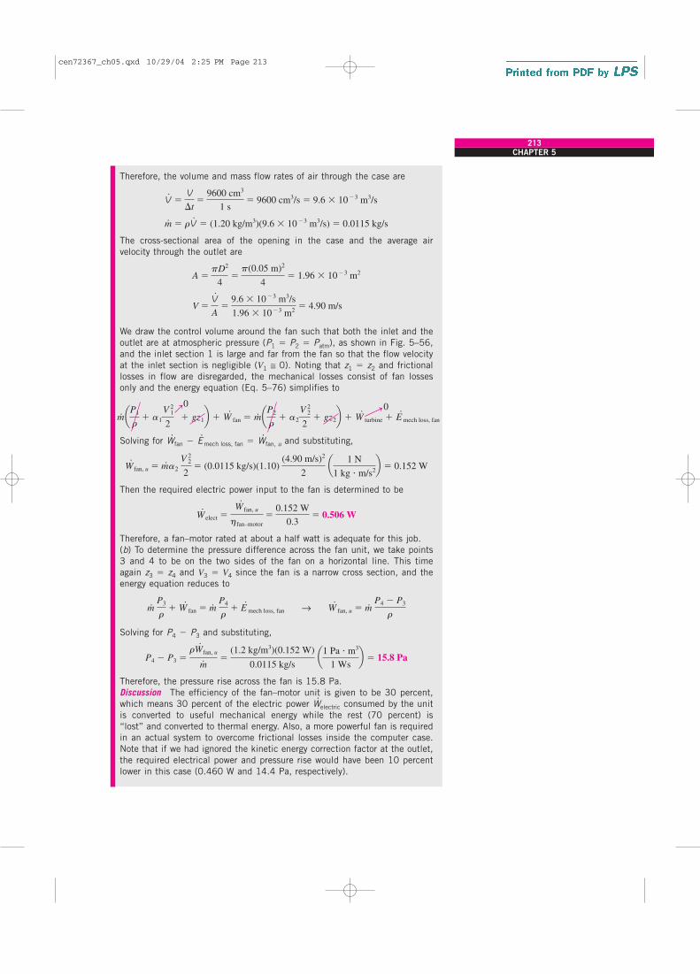
Therefore, the volume and mass flow rates of air through the case are
The cross-sectional area of the opening in the case and the average air
velocity through the outlet are
We draw the control volume around the fan such that both the inlet and the
outlet are at atmospheric pressure (P1 � P2 � Patm), as shown in Fig. 5–56,
and the inlet section 1 is large and far from the fan so that the flow velocity
at the inlet section is negligible (V1 ≅ 0). Noting that z1 � z2 and frictional
losses in flow are disregarded, the mechanical losses consist of fan losses
only and the energy equation (Eq. 5–76) simplifies to
Solving for W.fan � E
.mech loss, fan � W
.fan, u and substituting,
Then the required electric power input to the fan is determined to be
Therefore, a fan–motor rated at about a half watt is adequate for this job.
(b) To determine the pressure difference across the fan unit, we take points
3 and 4 to be on the two sides of the fan on a horizontal line. This time
again z3 � z4 and V3 � V4 since the fan is a narrow cross section, and the
energy equation reduces to
Solving for P4 � P3 and substituting,
Therefore, the pressure rise across the fan is 15.8 Pa.
Discussion The efficiency of the fan–motor unit is given to be 30 percent,
which means 30 percent of the electric power W.electric consumed by the unit
is converted to useful mechanical energy while the rest (70 percent) is
“lost” and converted to thermal energy. Also, a more powerful fan is required
in an actual system to overcome frictional losses inside the computer case.
Note that if we had ignored the kinetic energy correction factor at the outlet,
the required electrical power and pressure rise would have been 10 percent
lower in this case (0.460 W and 14.4 Pa, respectively).
P4 � P3 �rW#
fan, u
m# �
(1.2 kg/m3)(0.152 W)
0.0115 kg/s a1 Pa � m3
1 Wsb � 15.8 Pa
m# P3
r� W#
fan � m# P4
r� E#
mech loss, fan → W#
fan, u � m# P4 � P3
r
W#
elect �W#
fan, u
hfan–motor
�0.152 W
0.3� 0.506 W
W#
fan, u � m #a2
V 22
2� (0.0115 kg/s)(1.10)
(4.90 m/s)2
2 a 1 N
1 kg � m/s2b � 0.152 W
m# aP1
r� a1
V 21
2 � gz1b � W
#
fan � m# aP2
r� a2
V 22
2� gz2b � W
#
turbine � E#
mech loss, fan
V �V#
A�
9.6 � 10�3 m3/s
1.96 � 10�3 m2� 4.90 m/s
A �pD2
4�p(0.05 m)2
4� 1.96 � 10�3 m2
m#
� rV#
� (1.20 kg/m3)(9.6 � 10�3 m3/s) � 0.0115 kg/s
V#
�V
�t�
9600 cm3
1 s� 9600 cm3/s � 9.6 � 10�3 m3/s
213CHAPTER 5
0 0Q¡
cen72367_ch05.qxd 10/29/04 2:25 PM Page 213

EXAMPLE 5–15 Head and Power Loss During Water Pumping
Water is pumped from a lower reservoir to a higher reservoir by a pump that
provides 20 kW of useful mechanical power to the water (Fig. 5–57). The
free surface of the upper reservoir is 45 m higher than the surface of the
lower reservoir. If the flow rate of water is measured to be 0.03 m3/s, deter-
mine the irreversible head loss of the system and the lost mechanical power
during this process.
SOLUTION Water is pumped from a lower reservoir to a higher one. The
head and power loss associated with this process are to be determined.
Assumptions 1 The flow is steady and incompressible. 2 The elevation dif-
ference between the reservoirs is constant.
Properties We take the density of water to be 1000 kg/m3.
Analysis The mass flow rate of water through the system is
We choose points 1 and 2 at the free surfaces of the lower and upper reser-
voirs, respectively, and take the surface of the lower reservoir as the refer-
ence level (z1 � 0). Both points are open to the atmosphere (P1 � P2
� Patm) and the velocities at both locations are negligible (V1 � V2 � 0).
Then the energy equation for steady incompressible flow for a control volume
between 1 and 2 reduces to
W.
pump � m.gz2 � E
.mech, loss → E
.mech, loss � W
.pump � m
.gz2
Substituting, the lost mechanical power and head loss are determined to be
� 6.76 kW
Noting that the entire mechanical losses are due to frictional losses in piping
and thus E�mech, loss � E
�mech, loss, piping, the irreversible head loss is determined
to be
Discussion The 6.76 kW of power is used to overcome the friction in the
piping system. Note that the pump could raise the water an additional 23 m
if there were no irreversible head losses in the system. In this ideal case, the
pump would function as a turbine when the water is allowed to flow from the
upper reservoir to the lower reservoir and extract 20 kW of power from the
water.
hL �E#
mech loss, piping
m#g
�6.76 kW
(30 kg/s)(9.81 m/s2) a1 kg � m/s2
1 Nb a1000 N � m/s
1 kWb � 23.0 m
E#
mech, loss � 20 kW � (30 kg/s)(9.81 m/s2)(45 m)a 1 N
1 kg � m/s2b a 1 kW
1000 N � m/sb
� m# aP2
r� a2
V 22
2 � gz2b � W
#
turbine � E#
mech, loss
m# aP1
r� a1
V 21
2 � gz1 b � W
#
pump
m#
� rV#
� (1000 kg/m3)(0.03 m3/s) � 30 kg/s
214FLUID MECHANICS
00
¡
Q Q
Q
0.03 m3/s
z1 = 01
45 m
2
Pump
Controlsurface
20 kW
FIGURE 5–57
Schematic for Example 5–15.
0 0
cen72367_ch05.qxd 10/29/04 2:25 PM Page 214
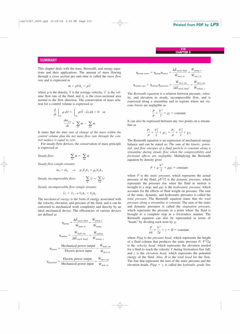
CHAPTER 5
215215CHAPTER 5
SUMMARY
This chapter deals with the mass, Bernoulli, and energy equa-tions and their applications. The amount of mass flowingthrough a cross section per unit time is called the mass flow
rate and is expressed as
where r is the density, V is the average velocity, V.
is the vol-ume flow rate of the fluid, and Ac is the cross-sectional areanormal to the flow direction. The conservation of mass rela-tion for a control volume is expressed as
It states that the time rate of change of the mass within the
control volume plus the net mass flow rate through the con-
trol surface is equal to zero.
For steady-flow devices, the conservation of mass principleis expressed as
Steady flow:
Steady flow (single stream):
Steady, incompressible flow:
Steady, incompressible flow (single stream):
The mechanical energy is the form of energy associated withthe velocity, elevation, and pressure of the fluid, and it can beconverted to mechanical work completely and directly by anideal mechanical device. The efficiencies of various devicesare defined as
hgenerator �Electric power output
Mechanical power input�
W#
elect, out
W#
shaft, in
hmotor �Mechanical power output
Electric power input�
W#
shaft, out
W#
elect, in
hturbine �W#
shaft, out
0�E#
mech, fluid 0 �W#
turbine
W#
turbine, e
hpump ��E#
mech, fluid
W#
shaft, in
�W#
pump, u
W#
pump
V#
1 � V#
2 → V1A1 � V2A2
ain
V#
� aout
V#
m#
1 � m#
2 → r1V1A1 � r2V2A2
ain
m#
� aout
m#
dmCV
dt� a
in
m#
� aout
m#
d
dt �
CV
r dV � �CS
r(V→
� n→) dA � 0 or
m#
� rVAc � rV#
The Bernoulli equation is a relation between pressure, veloc-ity, and elevation in steady, incompressible flow, and isexpressed along a streamline and in regions where net vis-cous forces are negligible as
It can also be expressed between any two points on a stream-line as
The Bernoulli equation is an expression of mechanical energybalance and can be stated as: The sum of the kinetic, poten-
tial, and flow energies of a fluid particle is constant along a
streamline during steady flow when the compressibility and
frictional effects are negligible. Multiplying the Bernoulliequation by density gives
where P is the static pressure, which represents the actualpressure of the fluid; rV2/2 is the dynamic pressure, whichrepresents the pressure rise when the fluid in motion isbrought to a stop; and rgz is the hydrostatic pressure, whichaccounts for the effects of fluid weight on pressure. The sumof the static, dynamic, and hydrostatic pressures is called thetotal pressure. The Bernoulli equation states that the total
pressure along a streamline is constant. The sum of the staticand dynamic pressures is called the stagnation pressure,which represents the pressure at a point where the fluid isbrought to a complete stop in a frictionless manner. TheBernoulli equation can also be represented in terms of“heads” by dividing each term by g,
where P/rg is the pressure head, which represents the heightof a fluid column that produces the static pressure P; V2/2g
is the velocity head, which represents the elevation neededfor a fluid to reach the velocity V during frictionless free fall;and z is the elevation head, which represents the potentialenergy of the fluid. Also, H is the total head for the flow.The line that represents the sum of the static pressure and theelevation heads, P/rg � z, is called the hydraulic grade line
P
rg�
V 2
2g� z � H � constant
P � r V 2
2� rgz � constant
P1
r�
V 21
2� gz1 �
P2
r�
V 22
2� gz2
P
r�
V 2
2� gz � constant
hturbine–gen � hturbinehgenerator �W#
elect, out
0�E#
mech, fluid 0 �W#
elect, out
W#
turbine, e
hpump–motor � hpumphmotor ��E#
mech, fluid
W#
elect, in
�W#
pump, u
W#
elect, in
cen72367_ch05.qxd 10/29/04 2:25 PM Page 215

(HGL), and the line that represents the total head of the fluid,P/rg � V2/2g � z, is called the energy grade line (EGL).
The energy equation for steady, incompressible flow canbe expressed as
where
hturbine, e �wturbine, e
g�
W#
turbine, e
m#g
�W#
turbine
hturbinem#g
hpump, u �wpump, u
g�
W#
pump, u
m#g
�hpumpW
#
pump
m#g
�P2
rg� a2
V 22
2g� z2 � hturbine, e � hL
P1
rg� a1
V 21
2g� z1 � hpump, u
216FLUID MECHANICS
The mass, Bernoulli, and energy equations are three of themost fundamental relations in fluid mechanics, and they areused extensively in the chapters that follow. In Chap. 6, eitherthe Bernoulli equation or the energy equation is used togetherwith the mass and momentum equations to determine theforces and torques acting on fluid systems. In Chaps. 8 and14, the mass and energy equations are used to determine thepumping power requirements in fluid systems and in thedesign and analysis of turbomachinery. In Chaps. 12 and 13,the energy equation is also used to some extent in the analy-sis of compressible flow and open-channel flow.
emech, loss � u2 � u1 � qnet in
hL �emech loss, piping
g�
E#
mech loss, piping
m#g
REFERENCES AND SUGGESTED READING
1. C. T. Crowe, J. A. Roberson, and D. F. Elger. Engineering
Fluid Mechanics, 7th ed. New York: Wiley, 2001.
2. R. C. Dorf, ed. in chief. The Engineering Handbook. BocaRaton, FL: CRC Press, 1995.
3. B. R. Munson, D. F. Young, and T. Okiishi. Fundamentals
of Fluid Mechanics, 4th ed. New York: Wiley, 2002.
4. R. L. Panton. Incompressible Flow, 2nd ed. New York:Wiley, 1996.
5. M. C. Potter and D. C. Wiggert. Mechanics of Fluids, 2nded. Upper Saddle River, NJ: Prentice Hall, 1997.
6. M. Van Dyke. An Album of Fluid Motion. Stanford, CA:The Parabolic Press, 1982.
PROBLEMS*
Conservation of Mass
5–1C Name four physical quantities that are conserved andtwo quantities that are not conserved during a process.
5–2C Define mass and volume flow rates. How are theyrelated to each other?
5–3C Does the amount of mass entering a control volumehave to be equal to the amount of mass leaving during anunsteady-flow process?
5–4C When is the flow through a control volume steady?
5–5C Consider a device with one inlet and one outlet. If thevolume flow rates at the inlet and at the outlet are the same,is the flow through this device necessarily steady? Why?
5–6E A garden hose attached with a nozzle is used to fill a20-gal bucket. The inner diameter of the hose is 1 in and itreduces to 0.5 in at the nozzle exit. If the average velocity inthe hose is 8 ft/s, determine (a) the volume and mass flowrates of water through the hose, (b) how long it will take tofill the bucket with water, and (c) the average velocity ofwater at the nozzle exit.
5–7 Air enters a nozzle steadily at 2.21 kg/m3 and 30 m/sand leaves at 0.762 kg/m3 and 180 m/s. If the inlet area of thenozzle is 80 cm2, determine (a) the mass flow rate throughthe nozzle, and (b) the exit area of the nozzle. Answers:
(a) 0.530 kg/s, (b) 38.7 cm2
5–8 A hair dryer is basically a duct of constant diameter inwhich a few layers of electric resistors are placed. A small
1.05 kg/m3 1.20 kg/m3
FIGURE P5–8
* Problems designated by a “C” are concept questions, and
students are encouraged to answer them all. Problems designated
by an “E” are in English units, and the SI users can ignore them.
Problems with the icon are solved using EES, and complete
solutions together with parametric studies are included on the
enclosed DVD. Problems with the icon are comprehensive in
nature and are intended to be solved with a computer, preferably
using the EES software that accompanies this text.
cen72367_ch05.qxd 10/29/04 2:25 PM Page 216

CHAPTER 5
217
5–13 A smoking lounge is to accommodate 15 heavysmokers. The minimum fresh air requirement for smokinglounges is specified to be 30 L/s per person (ASHRAE, Stan-dard 62, 1989). Determine the minimum required flow rate offresh air that needs to be supplied to the lounge, and thediameter of the duct if the air velocity is not to exceed 8 m/s.
217CHAPTER 5
Bathroom22°C
Fan
30 L/s
FIGURE P5–11
Air
outlet
Exhaust
fan
Air
inlet
FIGURE P5–12
5–12 A desktop computer is to be cooled by a fan whoseflow rate is 0.34 m3/min. Determine the mass flow rate of airthrough the fan at an elevation of 3400 m where the air den-sity is 0.7 kg/m3. Also, if the average velocity of air is not toexceed 110 m/min, determine the diameter of the casing ofthe fan. Answers: 0.238 kg/min, 0.063 m
Smokinglounge
15 smokersFan
FIGURE P5–13
5–14 The minimum fresh air requirement of a residentialbuilding is specified to be 0.35 air change per hour(ASHRAE, Standard 62, 1989). That is, 35 percent of theentire air contained in a residence should be replaced byfresh outdoor air every hour. If the ventilation requirement ofa 2.7-m-high, 200-m2 residence is to be met entirely by a fan,determine the flow capacity in L/min of the fan that needs tobe installed. Also determine the diameter of the duct if the airvelocity is not to exceed 6 m/s.
fan pulls the air in and forces it through the resistors where itis heated. If the density of air is 1.20 kg/m3 at the inlet and1.05 kg/m3 at the exit, determine the percent increase in thevelocity of air as it flows through the dryer.
5–9E Air whose density is 0.078 lbm/ft3 enters the duct ofan air-conditioning system at a volume flow rate of 450ft3/min. If the diameter of the duct is 10 in, determine thevelocity of the air at the duct inlet and the mass flow rate ofair.
5–10 A 1-m3 rigid tank initially contains air whose densityis 1.18 kg/m3. The tank is connected to a high-pressure sup-ply line through a valve. The valve is opened, and air isallowed to enter the tank until the density in the tank rises to7.20 kg/m3. Determine the mass of air that has entered thetank. Answer: 6.02 kg
5–11 The ventilating fan of the bathroom of a building hasa volume flow rate of 30 L/s and runs continuously. If thedensity of air inside is 1.20 kg/m3, determine the mass of airvented out in one day.
cen72367_ch05.qxd 10/29/04 2:25 PM Page 217

Mechanical Energy and Efficiency
5–15C What is mechanical energy? How does it differ fromthermal energy? What are the forms of mechanical energy ofa fluid stream?
5–16C What is mechanical efficiency? What does a mechan-ical efficiency of 100 percent mean for a hydraulic turbine?
5–17C How is the combined pump–motor efficiency of apump and motor system defined? Can the combined pump–motor efficiency be greater than either the pump or the motorefficiency?
5–18C Define turbine efficiency, generator efficiency, andcombined turbine–generator efficiency.
5–19 Consider a river flowing toward a lake at an averagevelocity of 3 m/s at a rate of 500 m3/s at a location 90 mabove the lake surface. Determine the total mechanical energyof the river water per unit mass and the power generationpotential of the entire river at that location. Answer: 444 MW
218FLUID MECHANICS
5–24 Water is pumped from a lake to a storage tank 20 mabove at a rate of 70 L/s while consuming 20.4 kW of elec-tric power. Disregarding any frictional losses in the pipes andany changes in kinetic energy, determine (a) the overall effi-ciency of the pump–motor unit and (b) the pressure differ-ence between the inlet and the exit of the pump.
∆T = 0.072°F
Pump
FIGURE P5–23E
5–20 Electric power is to be generated by installing ahydraulic turbine–generator at a site 70 m below the free sur-face of a large water reservoir that can supply water at a rateof 1500 kg/s steadily. If the mechanical power output of theturbine is 800 kW and the electric power generation is 750 kW,determine the turbine efficiency and the combinedturbine–generator efficiency of this plant. Neglect losses inthe pipes.
5–21 At a certain location, wind is blowing steadily at12 m/s. Determine the mechanical energy of air per unit massand the power generation potential of a wind turbine with 50-m-diameter blades at that location. Also determine the actualelectric power generation assuming an overall efficiency of30 percent. Take the air density to be 1.25 kg/m3.
5–22 Reconsider Prob. 5–21. Using EES (or other)software, investigate the effect of wind velocity
and the blade span diameter on wind power generation. Letthe velocity vary from 5 to 20 m/s in increments of 5 m/s,and the diameter to vary from 20 to 80 m in increments of 20m. Tabulate the results, and discuss their significance.
5–23E A differential thermocouple with sensors at the inletand exit of a pump indicates that the temperature of water rises0.072°F as it flows through the pump at a rate of 1.5 ft3/s. Ifthe shaft power input to the pump is 27 hp, determine themechanical efficiency of the pump. Answer: 64.7 percent
Pump
Storage tank
20 m
FIGURE P5–24
River 3 m/s
90 m
FIGURE P5–19
Bernoulli Equation
5–25C What is streamwise acceleration? How does it differfrom normal acceleration? Can a fluid particle accelerate insteady flow?
5–26C Express the Bernoulli equation in three differentways using (a) energies, (b) pressures, and (c) heads.
5–27C What are the three major assumptions used in thederivation of the Bernoulli equation?
5–28C Define static, dynamic, and hydrostatic pressure.Under what conditions is their sum constant for a flowstream?
5–29C What is stagnation pressure? Explain how it can bemeasured.
5–30C Define pressure head, velocity head, and elevationhead for a fluid stream and express them for a fluid streamwhose pressure is P, velocity is V, and elevation is z.
5–31C What is the hydraulic grade line? How does it differfrom the energy grade line? Under what conditions do bothlines coincide with the free surface of a liquid?
5–32C How is the location of the hydraulic grade line deter-mined for open-channel flow? How is it determined at theoutlet of a pipe discharging to the atmosphere?
cen72367_ch05.qxd 10/29/04 2:25 PM Page 218

CHAPTER 5
219
5–33C The water level of a tank on a building roof is 20 mabove the ground. A hose leads from the tank bottom to theground. The end of the hose has a nozzle, which is pointedstraight up. What is the maximum height to which the watercould rise? What factors would reduce this height?
5–34C In a certain application, a siphon must go over ahigh wall. Can water or oil with a specific gravity of 0.8 goover a higher wall? Why?
5–35C Explain how and why a siphon works. Someoneproposes siphoning cold water over a 7-m-high wall. Is thisfeasible? Explain.
5–36C A student siphons water over a 8.5-m-high wall atsea level. She then climbs to the summit of Mount Shasta(elevation 4390 m, Patm � 58.5 kPa) and attempts the sameexperiment. Comment on her prospects for success.
5–37C A glass manometer with oil as the working fluid isconnected to an air duct as shown in Fig. P5–37C. Will theoil in the manometer move as in Fig. P5–37Ca or b? Explain.What would your response be if the flow direction isreversed?
shoots up to 34 m. Estimate the gage pressure of water in thepipe. State your assumptions and discuss if the actual pres-sure is more or less than the value you predicted.
5–40 A Pitot-static probe is used to measure the velocity ofan aircraft flying at 3000 m. If the differential pressure read-ing is 3 kPa, determine the velocity of the aircraft.
5–41 While traveling on a dirt road, the bottom of a car hitsa sharp rock and a small hole develops at the bottom of itsgas tank. If the height of the gasoline in the tank is 30 cm,determine the initial velocity of the gasoline at the hole. Dis-cuss how the velocity will change with time and how theflow will be affected if the lid of the tank is closed tightly.Answer: 2.43 m/s
5–42E The drinking water needs of an office are metby large water bottles. One end of a 0.25-in-
diameter plastic hose is inserted into the bottle placed on ahigh stand, while the other end with an on/off valve is main-tained 2 ft below the bottom of the bottle. If the water levelin the bottle is 1.5 ft when it is full, determine how long itwill take at the minimum to fill an 8-oz glass (� 0.00835 ft3)(a) when the bottle is first opened and (b) when the bottle isalmost empty.
219CHAPTER 5
Flow Flow
(a) (b)
FIGURE P5–37C
Flow
12
FIGURE P5–38C
5–38C The velocity of a fluid flowing in a pipe is to bemeasured by two different Pitot-type mercury manometersshown in Fig. P5–38C. Would you expect both manometersto predict the same velocity for flowing water? If not, whichwould be more accurate? Explain. What would your responsebe if air were flowing in the pipe instead of water?
Water1.5 ft
2 ft
FIGURE P5–42E
5–39 In cold climates, water pipes may freeze and burst ifproper precautions are not taken. In such an occurrence, theexposed part of a pipe on the ground ruptures, and water
5–43 A piezometer and a Pitot tube are tapped into a 3-cm-diameter horizontal water pipe, and the height of the watercolumns are measured to be 20 cm in the piezometer and 35cm in the Pitot tube (both measured from the top surface ofthe pipe). Determine the velocity at the center of the pipe.
5–44 The diameter of a cylindrical water tank is Do and itsheight is H. The tank is filled with water, which is open tothe atmosphere. An orifice of diameter Do with a smoothentrance (i.e., no losses) is open at the bottom. Develop arelation for the time required for the tank (a) to emptyhalfway and (b) to empty completely.
cen72367_ch05.qxd 10/29/04 2:25 PM Page 219
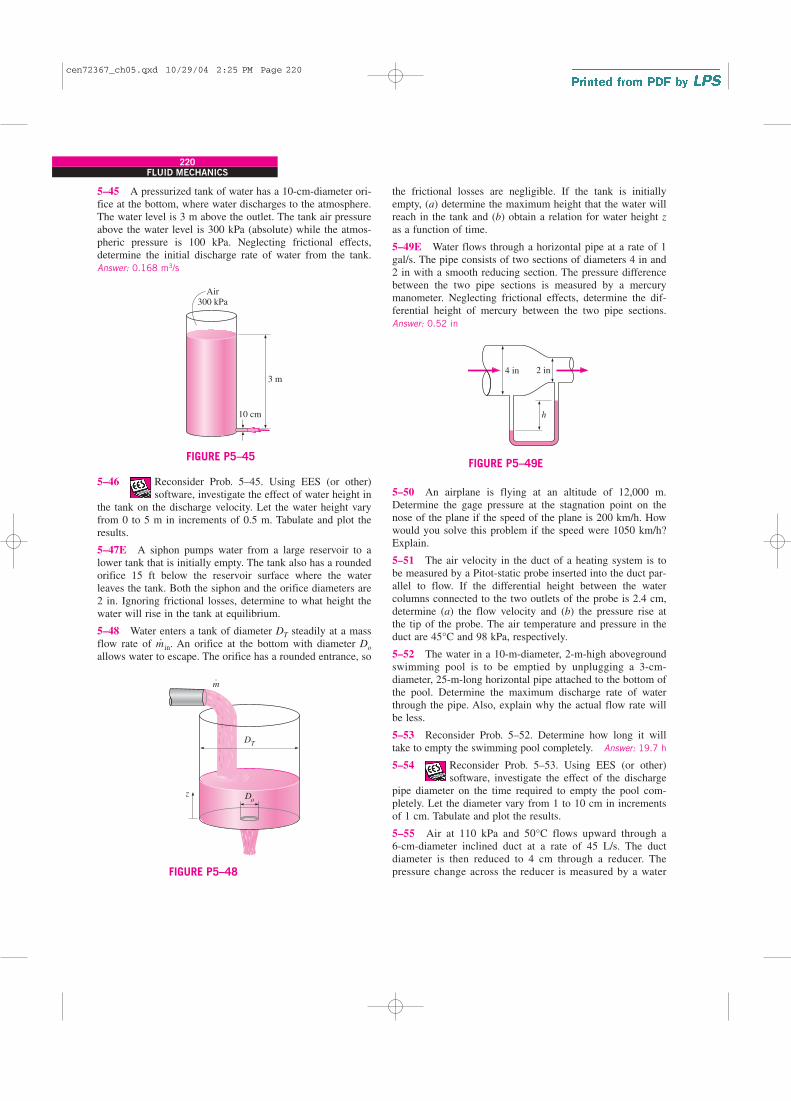
5–45 A pressurized tank of water has a 10-cm-diameter ori-fice at the bottom, where water discharges to the atmosphere.The water level is 3 m above the outlet. The tank air pressureabove the water level is 300 kPa (absolute) while the atmos-pheric pressure is 100 kPa. Neglecting frictional effects,determine the initial discharge rate of water from the tank.Answer: 0.168 m3/s
220FLUID MECHANICS
the frictional losses are negligible. If the tank is initiallyempty, (a) determine the maximum height that the water willreach in the tank and (b) obtain a relation for water height zas a function of time.
5–49E Water flows through a horizontal pipe at a rate of 1gal/s. The pipe consists of two sections of diameters 4 in and2 in with a smooth reducing section. The pressure differencebetween the two pipe sections is measured by a mercurymanometer. Neglecting frictional effects, determine the dif-ferential height of mercury between the two pipe sections.Answer: 0.52 in
Doz
DT
m⋅
FIGURE P5–48
5–46 Reconsider Prob. 5–45. Using EES (or other)software, investigate the effect of water height in
the tank on the discharge velocity. Let the water height varyfrom 0 to 5 m in increments of 0.5 m. Tabulate and plot theresults.
5–47E A siphon pumps water from a large reservoir to alower tank that is initially empty. The tank also has a roundedorifice 15 ft below the reservoir surface where the waterleaves the tank. Both the siphon and the orifice diameters are2 in. Ignoring frictional losses, determine to what height thewater will rise in the tank at equilibrium.
5–48 Water enters a tank of diameter DT steadily at a massflow rate of m
.in. An orifice at the bottom with diameter Do
allows water to escape. The orifice has a rounded entrance, so
4 in 2 in
h
FIGURE P5–49E
3 m
10 cm
Air300 kPa
FIGURE P5–45
5–50 An airplane is flying at an altitude of 12,000 m.Determine the gage pressure at the stagnation point on thenose of the plane if the speed of the plane is 200 km/h. Howwould you solve this problem if the speed were 1050 km/h?Explain.
5–51 The air velocity in the duct of a heating system is tobe measured by a Pitot-static probe inserted into the duct par-allel to flow. If the differential height between the watercolumns connected to the two outlets of the probe is 2.4 cm,determine (a) the flow velocity and (b) the pressure rise atthe tip of the probe. The air temperature and pressure in theduct are 45°C and 98 kPa, respectively.
5–52 The water in a 10-m-diameter, 2-m-high abovegroundswimming pool is to be emptied by unplugging a 3-cm-diameter, 25-m-long horizontal pipe attached to the bottom ofthe pool. Determine the maximum discharge rate of waterthrough the pipe. Also, explain why the actual flow rate willbe less.
5–53 Reconsider Prob. 5–52. Determine how long it willtake to empty the swimming pool completely. Answer: 19.7 h
5–54 Reconsider Prob. 5–53. Using EES (or other)software, investigate the effect of the discharge
pipe diameter on the time required to empty the pool com-pletely. Let the diameter vary from 1 to 10 cm in incrementsof 1 cm. Tabulate and plot the results.
5–55 Air at 110 kPa and 50°C flows upward through a 6-cm-diameter inclined duct at a rate of 45 L/s. The ductdiameter is then reduced to 4 cm through a reducer. Thepressure change across the reducer is measured by a water
cen72367_ch05.qxd 10/29/04 2:25 PM Page 220

CHAPTER 5
221
manometer. The elevation difference between the two pointson the pipe where the two arms of the manometer areattached is 0.20 m. Determine the differential height betweenthe fluid levels of the two arms of the manometer.
5–60 A Pitot-static probe connected to a water manometeris used to measure the velocity of air. If the deflection (thevertical distance between the fluid levels in the two arms) is7.3 cm, determine the air velocity. Take the density of air tobe 1.25 kg/m3.
221CHAPTER 5
Air
h
FIGURE P5–55
2.6 in
12.2 psia
Air 1.8 in
11.8 psia
FIGURE P5–56E
5–56E Air is flowing through a venturi meter whose diame-ter is 2.6 in at the entrance part (location 1) and 1.8 in at thethroat (location 2). The gage pressure is measured to be 12.2psia at the entrance and 11.8 psia at the throat. Neglectingfrictional effects, show that the volume flow rate can beexpressed as
and determine the flow rate of air. Take the air density to be0.075 lbm/ft3.
V#
� A2B2(P1 � P2)
r(1 � A22/A
21)
5 cm Air
0.3 cm
10 cm
20 cm
Liquidrising
FIGURE P5–58
5–57 The water pressure in the mains of a city at a particu-lar location is 400 kPa gage. Determine if this main can servewater to neighborhoods that are 50 m above this location.
5–58 A handheld bicycle pump can be used as an atomizerto generate a fine mist of paint or pesticide by forcing air at ahigh velocity through a small hole and placing a short tubebetween the liquid reservoir and the high-speed air jet whoselow pressure drives the liquid up through the tube. In such anatomizer, the hole diameter is 0.3 cm, the vertical distancebetween the liquid level in the tube and the hole is 10 cm,and the bore (diameter) and the stroke of the air pump are 5cm and 20 cm, respectively. If the atmospheric conditions are20°C and 95 kPa, determine the minimum speed that the pis-ton must be moved in the cylinder during pumping to initiatethe atomizing effect. The liquid reservoir is open to the atmo-sphere.
Pitot-staticprobe
Manometer
Air 7.3 cm
FIGURE P5–60
20 m
2 atm
h
FIGURE P5–59
5–59 The water level in a tank is 20 m above the ground. Ahose is connected to the bottom of the tank, and the nozzle atthe end of the hose is pointed straight up. The tank cover isairtight, and the air pressure above the water surface is 2 atmgage. The system is at sea level. Determine the maximumheight to which the water stream could rise. Answer: 40.7 m
5–61E The air velocity in a duct is measured by a Pitot-staticprobe connected to a differential pressure gage. If the air is at13.4 psia absolute and 70°F and the reading of the differen-tial pressure gage is 0.15 psi, determine the air velocity.Answer: 143 ft/s
cen72367_ch05.qxd 10/29/04 2:25 PM Page 221

5–62 In a hydroelectric power plant, water enters the tur-bine nozzles at 700 kPa absolute with a low velocity. If thenozzle outlets are exposed to atmospheric pressure of 100 kPa,determine the maximum velocity to which water can beaccelerated by the nozzles before striking the turbine blades.
Energy Equation
5–63C Consider the steady adiabatic flow of an incom-pressible fluid. Can the temperature of the fluid decrease dur-ing flow? Explain.
5–64C Consider the steady adiabatic flow of an incom-pressible fluid. If the temperature of the fluid remains con-stant during flow, is it accurate to say that the frictionaleffects are negligible?
5–65C What is irreversible head loss? How is it related tothe mechanical energy loss?
5–66C What is useful pump head? How is it related to thepower input to the pump?
5–67C What is the kinetic energy correction factor? Is itsignificant?
5–68C The water level in a tank is 20 m above the ground.A hose is connected to the bottom of the tank, and the nozzleat the end of the hose is pointed straight up. The water streamfrom the nozzle is observed to rise 25 m above the ground.Explain what may cause the water from the hose to riseabove the tank level.
5–69 Underground water is to be pumped by a 70 percentefficient 3-kW submerged pump to a pool whose free surfaceis 30 m above the underground water level. The diameter ofthe pipe is 7 cm on the intake side and 5 cm on the dischargeside. Determine (a) the maximum flow rate of water and(b) the pressure difference across the pump. Assume the eleva-tion difference between the pump inlet and the outlet and theeffect of the kinetic energy correction factors to be negligible.
222FLUID MECHANICS
5–74 Water is being pumped from a large lake to a reser-voir 25 m above at a rate of 25 L/s by a 10-kW (shaft) pump.If the irreversible head loss of the piping system is 7 m,determine the mechanical efficiency of the pump. Answer:
78.5 percent
5–75 Reconsider Prob. 5–74. Using EES (or other)software, investigate the effect of irreversible
head loss on the mechanical efficiency of the pump. Let thehead loss vary from 0 to 15 m in increments of 1 m. Plot theresults, and discuss them.
5–76 A 7-hp (shaft) pump is used to raise water to a 15-mhigher elevation. If the mechanical efficiency of the pump is82 percent, determine the maximum volume flow rate ofwater.
5–77 Water flows at a rate of 0.035 m3/s in a horizontal pipewhose diameter is reduced from 15 cm to 8 cm by a reducer.If the pressure at the centerline is measured to be 470 kPaand 440 kPa before and after the reducer, respectively, deter-mine the irreversible head loss in the reducer. Take thekinetic energy correction factors to be 1.05. Answer: 0.68 m
5–78 The water level in a tank is 20 m above the ground. Ahose is connected to the bottom of the tank, and the nozzle atthe end of the hose is pointed straight up. The tank is at sea
30 m
Pool
FIGURE P5–69
Air
8 m/s
Exhaustfan
FIGURE P5–73
5–71E In a hydroelectric power plant, water flows from anelevation of 240 ft to a turbine, where electric power is gen-erated. For an overall turbine–generator efficiency of 83 per-cent, determine the minimum flow rate required to generate100 kW of electricity. Answer: 370 lbm/s
5–72E Reconsider Prob. 5–71E. Determine the flow rate ofwater if the irreversible head loss of the piping system betweenthe free surfaces of the source and the sink is 36 ft.
5–73 A fan is to be selected to ventilate a bathroomwhose dimensions are 2 m � 3 m � 3 m. The
air velocity is not to exceed 8 m/s to minimize vibration andnoise. The combined efficiency of the fan–motor unit to beused can be taken to be 50 percent. If the fan is to replace theentire volume of air in 10 min, determine (a) the wattage ofthe fan–motor unit to be purchased, (b) the diameter of thefan casing, and (c) the pressure difference across the fan.Take the air density to be 1.25 kg/m3 and disregard the effectof the kinetic energy correction factors.
5–70 Reconsider Prob. 5–69. Determine the flow rate ofwater and the pressure difference across the pump if the irre-versible head loss of the piping system is 5 m.
cen72367_ch05.qxd 10/29/04 2:25 PM Page 222
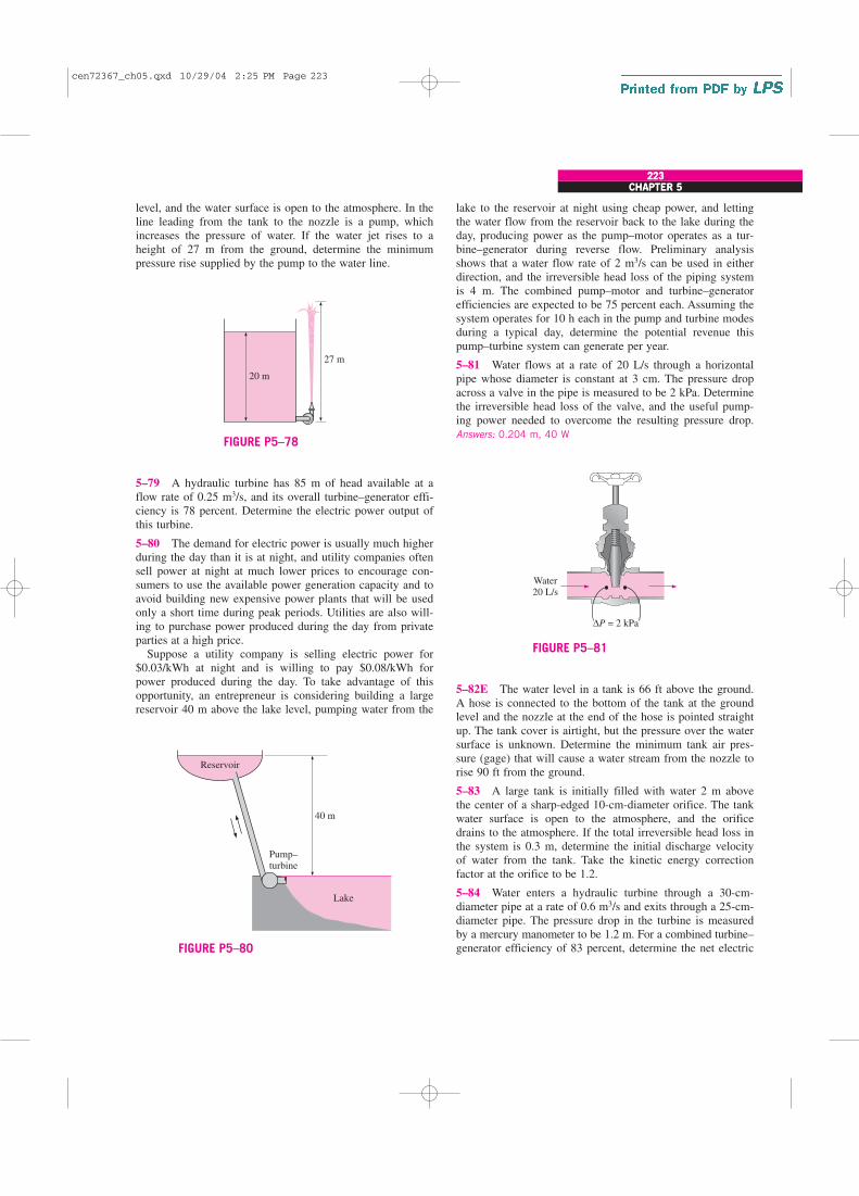
CHAPTER 5
223
level, and the water surface is open to the atmosphere. In theline leading from the tank to the nozzle is a pump, whichincreases the pressure of water. If the water jet rises to aheight of 27 m from the ground, determine the minimumpressure rise supplied by the pump to the water line.
lake to the reservoir at night using cheap power, and lettingthe water flow from the reservoir back to the lake during theday, producing power as the pump–motor operates as a tur-bine–generator during reverse flow. Preliminary analysisshows that a water flow rate of 2 m3/s can be used in eitherdirection, and the irreversible head loss of the piping systemis 4 m. The combined pump–motor and turbine–generatorefficiencies are expected to be 75 percent each. Assuming thesystem operates for 10 h each in the pump and turbine modesduring a typical day, determine the potential revenue thispump–turbine system can generate per year.
5–81 Water flows at a rate of 20 L/s through a horizontalpipe whose diameter is constant at 3 cm. The pressure dropacross a valve in the pipe is measured to be 2 kPa. Determinethe irreversible head loss of the valve, and the useful pump-ing power needed to overcome the resulting pressure drop.Answers: 0.204 m, 40 W
223CHAPTER 5
20 m
27 m
FIGURE P5–78
Pump–turbine
Lake
40 m
Reservoir
FIGURE P5–80
Water20 L/s
∆P = 2 kPa
FIGURE P5–81
5–82E The water level in a tank is 66 ft above the ground.A hose is connected to the bottom of the tank at the groundlevel and the nozzle at the end of the hose is pointed straightup. The tank cover is airtight, but the pressure over the watersurface is unknown. Determine the minimum tank air pres-sure (gage) that will cause a water stream from the nozzle torise 90 ft from the ground.
5–83 A large tank is initially filled with water 2 m abovethe center of a sharp-edged 10-cm-diameter orifice. The tankwater surface is open to the atmosphere, and the orificedrains to the atmosphere. If the total irreversible head loss inthe system is 0.3 m, determine the initial discharge velocityof water from the tank. Take the kinetic energy correctionfactor at the orifice to be 1.2.
5–84 Water enters a hydraulic turbine through a 30-cm-diameter pipe at a rate of 0.6 m3/s and exits through a 25-cm-diameter pipe. The pressure drop in the turbine is measuredby a mercury manometer to be 1.2 m. For a combined turbine–generator efficiency of 83 percent, determine the net electric
5–79 A hydraulic turbine has 85 m of head available at aflow rate of 0.25 m3/s, and its overall turbine–generator effi-ciency is 78 percent. Determine the electric power output ofthis turbine.
5–80 The demand for electric power is usually much higherduring the day than it is at night, and utility companies oftensell power at night at much lower prices to encourage con-sumers to use the available power generation capacity and toavoid building new expensive power plants that will be usedonly a short time during peak periods. Utilities are also will-ing to purchase power produced during the day from privateparties at a high price.
Suppose a utility company is selling electric power for$0.03/kWh at night and is willing to pay $0.08/kWh forpower produced during the day. To take advantage of thisopportunity, an entrepreneur is considering building a largereservoir 40 m above the lake level, pumping water from the
cen72367_ch05.qxd 10/29/04 2:25 PM Page 223
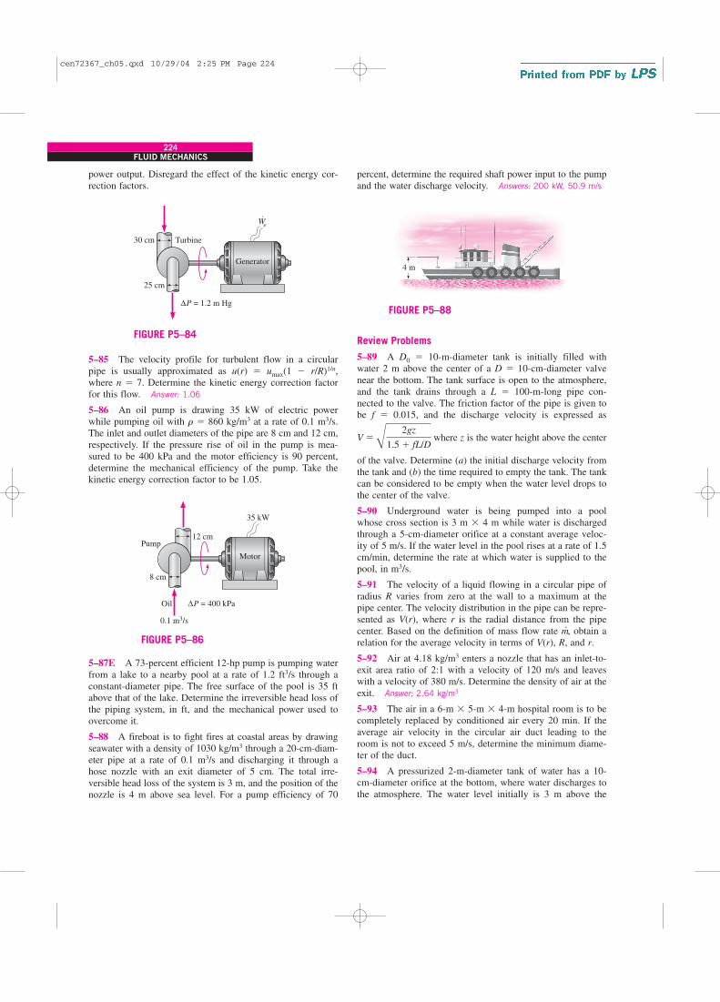
power output. Disregard the effect of the kinetic energy cor-rection factors.
224FLUID MECHANICS
percent, determine the required shaft power input to the pumpand the water discharge velocity. Answers: 200 kW, 50.9 m/s
35 kW
∆P = 400 kPa
0.1 m3/s
Motor
8 cm
12 cm
Oil
Pump
FIGURE P5–86
5–85 The velocity profile for turbulent flow in a circularpipe is usually approximated as u(r) � umax(1 � r/R)1/n,where n � 7. Determine the kinetic energy correction factorfor this flow. Answer: 1.06
5–86 An oil pump is drawing 35 kW of electric powerwhile pumping oil with r � 860 kg/m3 at a rate of 0.1 m3/s.The inlet and outlet diameters of the pipe are 8 cm and 12 cm,respectively. If the pressure rise of oil in the pump is mea-sured to be 400 kPa and the motor efficiency is 90 percent,determine the mechanical efficiency of the pump. Take thekinetic energy correction factor to be 1.05.
4 m
FIGURE P5–88
5–87E A 73-percent efficient 12-hp pump is pumping waterfrom a lake to a nearby pool at a rate of 1.2 ft3/s through aconstant-diameter pipe. The free surface of the pool is 35 ftabove that of the lake. Determine the irreversible head loss ofthe piping system, in ft, and the mechanical power used toovercome it.
5–88 A fireboat is to fight fires at coastal areas by drawingseawater with a density of 1030 kg/m3 through a 20-cm-diam-eter pipe at a rate of 0.1 m3/s and discharging it through ahose nozzle with an exit diameter of 5 cm. The total irre-versible head loss of the system is 3 m, and the position of thenozzle is 4 m above sea level. For a pump efficiency of 70
We
⋅
30 cm Turbine
∆P = 1.2 m Hg
Generator
25 cm
FIGURE P5–84Review Problems
5–89 A D0 � 10-m-diameter tank is initially filled withwater 2 m above the center of a D � 10-cm-diameter valvenear the bottom. The tank surface is open to the atmosphere,and the tank drains through a L � 100-m-long pipe con-nected to the valve. The friction factor of the pipe is given tobe f � 0.015, and the discharge velocity is expressed as
where z is the water height above the center
of the valve. Determine (a) the initial discharge velocity fromthe tank and (b) the time required to empty the tank. The tankcan be considered to be empty when the water level drops tothe center of the valve.
5–90 Underground water is being pumped into a poolwhose cross section is 3 m � 4 m while water is dischargedthrough a 5-cm-diameter orifice at a constant average veloc-ity of 5 m/s. If the water level in the pool rises at a rate of 1.5cm/min, determine the rate at which water is supplied to thepool, in m3/s.
5–91 The velocity of a liquid flowing in a circular pipe ofradius R varies from zero at the wall to a maximum at thepipe center. The velocity distribution in the pipe can be repre-sented as V(r), where r is the radial distance from the pipecenter. Based on the definition of mass flow rate m
., obtain a
relation for the average velocity in terms of V(r), R, and r.
5–92 Air at 4.18 kg/m3 enters a nozzle that has an inlet-to-exit area ratio of 2:1 with a velocity of 120 m/s and leaveswith a velocity of 380 m/s. Determine the density of air at theexit. Answer: 2.64 kg/m3
5–93 The air in a 6-m � 5-m � 4-m hospital room is to becompletely replaced by conditioned air every 20 min. If theaverage air velocity in the circular air duct leading to theroom is not to exceed 5 m/s, determine the minimum diame-ter of the duct.
5–94 A pressurized 2-m-diameter tank of water has a 10-cm-diameter orifice at the bottom, where water discharges tothe atmosphere. The water level initially is 3 m above the
V �B2gz
1.5 � fL/D
cen72367_ch05.qxd 10/29/04 2:25 PM Page 224
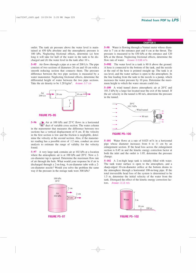
CHAPTER 5
225
outlet. The tank air pressure above the water level is main-tained at 450 kPa absolute and the atmospheric pressure is100 kPa. Neglecting frictional effects, determine (a) howlong it will take for half of the water in the tank to be dis-charged and (b) the water level in the tank after 10 s.
5–95 Air flows through a pipe at a rate of 200 L/s. The pipeconsists of two sections of diameters 20 cm and 10 cm with asmooth reducing section that connects them. The pressuredifference between the two pipe sections is measured by awater manometer. Neglecting frictional effects, determine thedifferential height of water between the two pipe sections.Take the air density to be 1.20 kg/m3. Answer: 3.7 cm
5–98 Water is flowing through a Venturi meter whose diam-eter is 7 cm at the entrance part and 4 cm at the throat. Thepressure is measured to be 430 kPa at the entrance and 120kPa at the throat. Neglecting frictional effects, determine theflow rate of water. Answer: 0.538 m3/s
5–99E The water level in a tank is 80 ft above the ground.A hose is connected to the bottom of the tank, and the nozzleat the end of the hose is pointed straight up. The tank is atsea level, and the water surface is open to the atmosphere. Inthe line leading from the tank to the nozzle is a pump, whichincreases the water pressure by 10 psia. Determine the maxi-mum height to which the water stream could rise.
5–100 A wind tunnel draws atmospheric air at 20°C and101.3 kPa by a large fan located near the exit of the tunnel. Ifthe air velocity in the tunnel is 80 m/s, determine the pressurein the tunnel.
20 cmAir
200 L/s10 cm
h
FIGURE P5–95
2 cmAir102 kPa
100 kPa20°C
2 cm
4 cm
FIGURE P5–97
5–96 Air at 100 kPa and 25°C flows in a horizontalduct of variable cross section. The water column
in the manometer that measures the difference between twosections has a vertical displacement of 8 cm. If the velocityin the first section is low and the friction is negligible, deter-mine the velocity at the second section. Also, if the manome-ter reading has a possible error of 2 mm, conduct an erroranalysis to estimate the range of validity for the velocityfound.
5–97 A very large tank contains air at 102 kPa at a locationwhere the atmospheric air is at 100 kPa and 20°C. Now a 2-cm-diameter tap is opened. Determine the maximum flow rateof air through the hole. What would your response be if air isdischarged through a 2-m-long, 4-cm-diameter tube with a 2-cm-diameter nozzle? Would you solve the problem the sameway if the pressure in the storage tank were 300 kPa?
20°C101.3 kPa
Wind tunnel
80 m/s
FIGURE P5–100
2 mWater
10 cm100 m
FIGURE P5–102
5–101 Water flows at a rate of 0.025 m3/s in a horizontalpipe whose diameter increases from 6 to 11 cm by anenlargement section. If the head loss across the enlargementsection is 0.45 m and the kinetic energy correction factor atboth the inlet and the outlet is 1.05, determine the pressurechange.
5–102 A 2-m-high large tank is initially filled with water.The tank water surface is open to the atmosphere, and asharp-edged 10-cm-diameter orifice at the bottom drains tothe atmosphere through a horizontal 100-m-long pipe. If thetotal irreversible head loss of the system is determined to be1.5 m, determine the initial velocity of the water from thetank. Disregard the effect of the kinetic energy correction fac-tors. Answer: 3.13 m/s
cen72367_ch05.qxd 10/29/04 2:25 PM Page 225

5–103 Reconsider Prob. 5–102. Using EES (or other)software, investigate the effect of the tank
height on the initial discharge velocity of water from thecompletely filled tank. Let the tank height vary from 2 to 15m in increments of 1 m, and assume the irreversible head lossto remain constant. Tabulate and plot the results.
5–104 Reconsider Prob. 5–102. In order to drain the tankfaster, a pump is installed near the tank exit. Determine thepump head input necessary to establish an average watervelocity of 6 m/s when the tank is full.
Design and Essay Problems
5–105 Using a large bucket whose volume is known andmeasuring the time it takes to fill the bucket with water froma garden hose, determine the mass flow rate and the averagevelocity of water through the hose.
5–106 Your company is setting up an experiment thatinvolves the measurement of airflow rate in a duct, and youare to come up with proper instrumentation. Research theavailable techniques and devices for airflow rate measure-ment, discuss the advantages and disadvantages of each tech-nique, and make a recommendation.
5–107 Computer-aided designs, the use of better materials,and better manufacturing techniques have resulted in atremendous increase in the efficiency of pumps, turbines, andelectric motors. Contact several pump, turbine, and motormanufacturers and obtain information about the efficiency oftheir products. In general, how does efficiency vary withrated power of these devices?
226FLUID MECHANICS
5–108 Using a handheld bicycle pump to generate an airjet, a soda can as the water reservoir, and a straw as the tube,design and build an atomizer. Study the effects of variousparameters such as the tube length, the diameter of the exithole, and the pumping speed on performance.
5–109 Using a flexible drinking straw and a ruler, explainhow you would measure the water flow velocity in a river.
5–110 The power generated by a wind turbine is propor-tional to the cube of the wind velocity. Inspired by the accel-eration of a fluid in a nozzle, someone proposes to install areducer casing to capture the wind energy from a larger areaand accelerate it before the wind strikes the turbine blades, asshown in Fig. P5–110. Evaluate if the proposed modificationshould be given a consideration in the design of new windturbines.
Wind
FIGURE P5–110
cen72367_ch05.qxd 10/29/04 2:25 PM Page 226