
Masonry design for disproportionate collapse requirements ... · Masonry design for...
12
Masonry design for disproportionate collapse requirements under Regulation A3 of the Building Regulations (England & Wales) Introduction Revised Building Regulations for England & Wales, related, in part, to the structural design of buildings to resist accidental damage, have recently been published together with the relevant Approved Document giving guidance on accidental damage design. Although the changes are not quite so far reaching as they appear to be at first sight, they do have implications for the design of traditional masonry buildings. This Technical Note gives guidance on the design of masonry structures to be in accordance with the new disproportionate collapse requirements of the Regulations. Revised Building Regulations New requirements for dealing with accidental damage came into force on 1st December 2004, when Building Regulation A3 was changed. Approved Document A to the Building Regulations has been revised to give guidance on the manner in which the new A3 can be satisfied, but it is not specific to any material or form of construction. BS 5628: Part 1: 1992, in clause 37, gives guidance suitable for masonry buildings, in order to satisfy the accidental damage rules that applied prior to 1st December 2004. Note: BS 5628 will be revised to take into account the revision to A3 at the same time as references to the European Masonry Standards are incorporated. Building Classes The previous A3 requirements for accidental damage design, whilst assuming that a building would be robust when designed to BS Codes of Practice, exempted most practical masonry buildings, if they were of four storeys or less in height, including any basement storeys. Buildings of five storeys and above had to be designed to accommodate the rules for avoiding collapse, in the event of an accident, to an extent disproportionate to the cause. The new rules do not allow any exemptions, as such, but their effect is to allow houses of up to four storeys to be designed and built as they were previously. The design of four storey buildings, other than houses, is required to be only slightly different from before, and houses up to five storeys high may now be designed according to the rules for other buildings of up to four storeys. No definition of ‘storey’ is given in the Approved Document, but it has previously been defined as: ‘that part of a building which is situated between either: (a) the top surface of two vertically adjacent floors, or (b) the top surface of the uppermost floor and the surface covering of the building’. A basement may be disregarded in the determination of the number of storeys, if it is designed to be sufficiently robust. Practical masonry buildings can have varying numbers of storeys, or basements that can partly be excluded from the number to be considered. The NHBC has published a useful guide containing interpretation of the number of storeys in ‘NHBC Technical Guidance Note: The Building Regulations 2004 edition. Requirement A3. Disproportionate collapse’ 1
-
Upload
nguyenkhuong -
Category
Documents
-
view
221 -
download
2
Transcript of Masonry design for disproportionate collapse requirements ... · Masonry design for...
Masonry design for disproportionate collapse requirements under Regulation A3 of the Building Regulations (England & Wales)
Introduction
Revised Building Regulations for England & Wales, related, in part, to the structural design of buildings to resist accidental damage, have recently been published together with the relevant Approved Document giving guidance on accidental damage design. Although the changes are not quite so far reaching as they appear to be at fi rst sight, they do have implications for the design of traditional masonry buildings. This Technical Note gives guidance on the design of masonry structures to be in accordance with the new disproportionate collapse requirements of the Regulations.
Revised Building Regulations
New requirements for dealing with accidental damage came into force on 1st December 2004, when Building Regulation A3 was changed. Approved Document A to the Building Regulations has been revised to give guidance on the manner in which the new A3 can be satisfi ed, but it is not specifi c to any material or form of construction. BS 5628: Part 1: 1992, in clause 37, gives guidance suitable for masonry buildings, in order to satisfy the accidental damage rules that applied prior to 1st December 2004.
Note: BS 5628 will be revised to take into account the revision to A3 at the same time as references to the European Masonry Standards are incorporated.
Building Classes
The previous A3 requirements for accidental damage design, whilst assuming that a building would be robust when designed to BS Codes of Practice, exempted most practical masonry buildings, if they were of four storeys or less in height, including any basement storeys. Buildings of fi ve storeys and above had to be designed to accommodate the rules for avoiding collapse, in the event of an accident, to an extent disproportionate to the cause. The new rules do not allow any exemptions, as such, but their effect is to allow houses of up to four storeys to be designed and built as they were previously. The design of four storey buildings, other than houses, is required to be only slightly different from before, and houses up to fi ve storeys high may now be designed according to the rules for other buildings of up to four storeys.
No defi nition of ‘storey’ is given in the Approved Document, but it has previously been defi ned as:‘that part of a building which is situated between either:
(a) the top surface of two vertically adjacent fl oors, or
(b) the top surface of the uppermost fl oor and the surface covering of the building’.
A basement may be disregarded in the determination of the number of storeys, if it is designed to be suffi ciently robust. Practical masonry buildings can have varying numbers of storeys, or basements that can partly be excluded from the number to be considered. The NHBC has published a useful guide containing interpretation of the number of storeys in ‘NHBC Technical Guidance Note: The Building Regulations 2004 edition. Requirement A3. Disproportionate collapse’
1

Table 11 of the Approved Document to Regulation A3 defi nes Building Classes according to the type and occupancy of the building.
A simple representation of the application of the concept of classes to single occupancy houses, of various numbers of storeys, is shown in fi gure 1, below.
3 storey overbasement
1
6 storey overbasement
2B
4 storey overbasement
1 or2A
2B
5 storey overbasement
2A
2B
Figure 1: Illustration of the Class of single occupancy houses from 3 to 6 storeys
Design to satisfy Regulation A3
General
All buildings must be designed to satisfy either the Rules given in Section 2C of the Approved Document A, if applicable, or those of the relevant Code of Practice for resistance to loads and avoidance of undue defl ections, in other words to satisfy the ultimate limit state and serviceability limit state. The table below summarises the additional measures, according to the Approved Document, needed to meet the Regulation.
Table 1: Approved Document requirements for Class 1, 2A, 2B and 3 buildings
Building Class Design Requirement
Class 1 No specifi c additional measures required. No specifi c additional measures required.
Class 2A Provide effective horizontal ties or effective anchorage of suspended Provide effective horizontal ties or effective anchorage of suspended Class 2A Provide effective horizontal ties or effective anchorage of suspended Class 2A fl oors to walls as described in BS 5628: Part 1; 1992 Clause 28.2.2, fl oors to walls as described in BS 5628: Part 1; 1992 Clause 28.2.2, and Appendix C, if a strap is added to fi gures 23, 24 and 25. and Appendix C, if a strap is added to fi gures 23, 24 and 25.
Class 2B Either: provide horizontal ties, as described in Clause 37.3 and table 13, Either: provide horizontal ties, as described in Clause 37.3 and table 13, and vertical ties in accordance with Clause 37.4 and Table 14 of BS and vertical ties in accordance with Clause 37.4 and Table 14 of BS 5628: Part 1:1992 5628: Part 1:1992
Or: prove walls, columns, beams etc removable, one at a time, without Or: prove walls, columns, beams etc removable, one at a time, without causing collapse, unless designed as key elements (protected member causing collapse, unless designed as key elements (protected member in BS 5628: Part 1:1992). in BS 5628: Part 1:1992).
Class 3 Carry out systematic risk analysis taking into account all reasonably Carry out systematic risk analysis taking into account all reasonably foreseeable hazards and any abnormal hazards. foreseeable hazards and any abnormal hazards.
2

It can be seen that for houses of up to four storeys (Class 1 buildings), the new Approved Document does not require any change from existing practice, which has required certain connections between fl oors and walls. There is some difference in the requirements for Class 2A buildings, which will include fl ats, over Class 1 buildings, but these differences are readily met by adopting standard tying and anchorage details as contained within BS 5628: Part 1 and the measures are likely to have been carried out in the normal course of BS 5628 design. The main point for Class 2A buildings is that all fl oor elements must now be anchored to masonry walls, in order to form effective horizontal ties, but this can be achieved using details that are often incorporated, anyway. For class 2B buildings the requirements for class 2A buildings apply together with additional requirements including, either, provision of effective horizontal and vertical ties, or, assessment that the building remains safe, within limits set down, upon the notional removal of supports, one at a time.
Achieving the tying required for Class 1, 2A and 2B Buildings
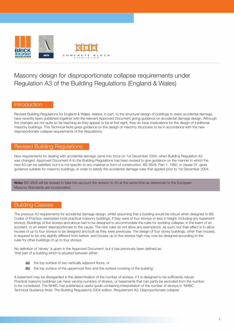
Typical details for tying, where horizontal restraint ties are required relevant to the Class of building, are given in the following fi gures (see also BS 8103: Part 1); the spacing of ties for Class 1 and 2A buildings is given in Table 2. Typically, horizontal restraint ties are of 30mm x 5mm section; when design is to BS 5628: Part 1 or BS 8103: Part 1, ties should be not less than 600mm in length, and should cross over 2 joists (for example fi gure 10), where relevant. AD A, Section 2C, requires that ties are not less than 1200mm in length, and cross over 3 joists.
Ties for Class 2B buildings must meet certain strength requirements (see Class 2B, below).
Table 2: Spacing of horizontal restraint ties for Class 1 and 2A buildings
Construction Spacing of horizontal restraint ties
Up to 3 storeys 4 storeys 5 storeys Up to 3 storeys 4 storeys 5 storeys Up to 3 storeys 4 storeys 5 storeys Up to 3 storeys 4 storeys 5 storeys
Houses of 2.0m† 1.25m 1.25m Houses of 2.0m† 1.25m 1.25m Houses of 2.0m† 1.25m 1.25m Houses of 2.0m† 1.25m 1.25m Class 1 and 2A Class 1 and 2A
Other buildings of 1.25m 1.25m Not applicable Other buildings of 1.25m 1.25m Not applicable Other buildings of 1.25m 1.25m Not applicable Other buildings of 1.25m 1.25m Not applicable Class 2A Class 2A
† When a fl oor bears not less than 90mm onto a wall, no horizontal restraint tie is required † When a fl oor bears not less than 90mm onto a wall, no horizontal restraint tie is required (only applies to two storey houses designed to AD A Section 2C). (only applies to two storey houses designed to AD A Section 2C).
Class 1 buildingsFigures 2 to 15 illustrate some of the ways in which the junction of fl oors and masonry walls will meet the requirements for houses, with the exception that the tension straps shown on fi gures 5, 6 and 7 are not required in Class 1 buildings
Class 2A buildingsFigures 3 to 15 illustrate some of the ways in which the junction of fl oors and masonry walls will meet the requirements.
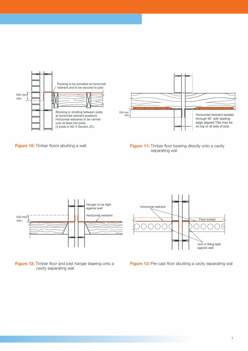
Class 2B buildingsThere are two approaches to designing Class 2B buildings; one requires the provision of effective horizontal ties, designed according to BS 5628: Part 1: 1992, clause 37.3 and Table 13, together with vertical loadbearing members being able to act as vertical ties according to clause 37.4 and Table 14 of BS 5628: Part 1. The ability to include vertical ties is dependent on there being vertical voids in the masonry that can accommodate reinforcing steel, grouted or concreted into the void. There are requirements for the minimum thickness and strength of walls incorporating ties, and for their strength, in BS 5628: Part 1. Suggested details of how to incorporate horizontal ties are given in fi gures 14 to 18 and for vertical ties, fi gures 19 to 22. Vertical ties need to be taken down to the foundations and securely fi xed to them.
3

The alternative approach is to show that loadbearing members, as defi ned in Table 3, can be notionally removed, one at a time, without causing collapse of a part of the building exceeding the limits given in Consideration of the removal of loadbearing members, below. Instead of considering the notional removal of a loadbearing member, it may be designed to resist a horizontal or vertical pressure of 34kN/m2 so as to be a key element (formerly called protected member). This Technical Note is not intended to cover engineered buildings fully, and does not give guidance on the design of key elements, which are covered in BS 5628: Part 1: 1992.
Consideration of the removal of loadbearing members
When considering the removal of any one of the loadbearing members, defi ned in Table 3, in a Class 2B masonry building, the structure above must remain stable, but it does not need to remain serviceable in this theoretical situation. In designing for the removal of a loadbearing wall, the partial safety factors that have to be used are reduced, according to BS 5628: Part 1 (see clauses 22 d) and 27.3). The Approved Document allows limited collapse of parts of a structure when a vertical support has been notionally removed, up to 15% of the fl oor area, but not more than 70m2 in the storey of the incident, the one below and the one above.
Table 3: Loadbearing Members
Type of loadbearing element Extent
Beam or slab supporting one Clear span between supports or between a support Beam or slab supporting one Clear span between supports or between a support or more columns or a loadbearing wall and the extremity of a member or more columns or a loadbearing wall and the extremity of a member
Column Clear height between horizontal lateral supports Column Clear height between horizontal lateral supports
Wall incorporating one or more lateral Length between vertical lateral supports or Wall incorporating one or more lateral Length between vertical lateral supports or supports (note 2) length between a vertical lateral support and the end of the wall supports (note 2) length between a vertical lateral support and the end of the wall
Wall without lateral supports Length not exceeding Wall without lateral supports Length not exceeding 2.25h anywhere along the wall (for internal walls) Full length (for external walls) (for internal walls) Full length (for external walls)
NOTE 1: Under Accidental loading conditions, temporary supports to slabs can be provided by substantial or other adequate partitions capable of carrying the required load. adequate partitions capable of carrying the required load.
NOTE 2: Lateral supports to walls can be provided by intersecting or return walls, piers, stiffened sections of wall, substantial non-loadbearing partitions (defi ned in Clause 37.5 c) of BS 5628: Part 1: 1992) or substantial non-loadbearing partitions (defi ned in Clause 37.5 c) of BS 5628: Part 1: 1992) or purpose-designed structural elements. purpose-designed structural elements.
By considering the way in which a structure above a wall that is being notionally removed is able to span over the missing wall, it can usually be demonstrated that collapse can be avoided, or kept to the allowable extent. Examples of how the structure above can be retained after the removal of a loadbearing member are described and illustrated below.
(a) Use the ability of a fl oor to span, albeit with a large defl ection, in the direction at right angles to that for which it was designed, or to span in one direction, rather than in two. See fi gure 23.
(b) By virtue of the tying reinforcement in a reinforced concrete fl oor, allow a slab to span two bays of masonry walls, accepting the large defl ection that will result. See fi gure 24.
(c) Use the ability of a masonry wall to cantilever as a deep beam over the notional opening resulting from consideration of the removal of a wall. See fi gure 25.
(d) In a similar way to (c), use the wall above as a deep beam to span over an opening between a corner and the rest of a wall. See fi gure 26.
4

Figure 2: Timber or concrete fl oor bearing directly onto a wall (minimum bearing 90mm) for 2 storey houses
100 mmmin.
Horizontal restraint twisted through 90˚ with leading edge aligned. Ties may be on top or at side of joist.
Figure 3: Timber fl oor bearing directly onto a wall
100 mmmin.
Hanger to be tight against wall
Alternative horizontal restraint positions
In houses up to three storeys no horizontalrestraint is required, provided that the joist is effectively tied to the hanger
300 mm min.
Horizontal restraint
Figure 4: Timber fl oor and joist hanger Figure 5: Timber fl oors and joist hangers on both side of a wall
5
Class 3 Buildings
The risk analysis of Class 3 buildings is beyond the scope of this technical Note.
Material alterations to a building
The recommendations in this Technical Note are primarily intended to apply to new buildings; when material alterations are to be made to a building, in may be necessary to comply with Regulation A3 in carrying out the alterations, but the manner of doing this is beyond the scope of this Note.
Examples of horizontal and vertical tying

Packing to be provided attie positions and to besecured to joist
Blocking or struttingbetween joists at tiepositionsTies to be carried overat least two joists
Figure 6: Timber fl oors abutting an internal wall
May be constructed in concrete
Unit or filling tightagainst wall
Floor screed
Horizontal restraint
Figure 7: Pre-cast fl oor abutting an internal wall
100 mmmin.
800 mm or two beams,whichever is the greater
May be constructed in concrete
Floor screed
Horizontal restraint
Figure 8: Beam and pot fl oor abutting a wall
100 mm
800 mm min.
May be constructed in concrete
Horizontal restraint
Floor screed
min.
Figure 9: Pre-cast fl oor abutting a wall
6
Packing to be provided at horizontal restraint and to be secured to joist
Blocking or strutting between joists at horizontal restraint positionsHorizontal restraints to be carried over at least two joists(3 joists in AD A Section 2C)
100 mmmin.
Figure 10: Timber fl oors abutting a wall
100 mmmin. Horizontal restraint twisted
through 90˚ with leading edge aligned.Ties may be on top or at side of joist.
Figure 11: Timber fl oor bearing directly onto a cavity separating wall
100 mmmin.
Hanger to be tight against wall
Horizontal restraint
Figure 12: Timber fl oor and joist hanger bearing onto a cavity separating wall
Unit or filling tightagainst wall
Floor screed
Horizontal restraint
Figure 13: Pre-cast fl oor abutting a cavity separating wall
7

Concrete topping
Figure 14: Floor ties within a screed
Insitu concrete
Tie bar Internal tie
Figure 15: Floor ties in hollow cores
Insitu concreteTie bar
Longitudinal bar
Figure 16: Perimeter ties within hollow cores
Tie bar
Figure 17: Ties within longitudinal joints
8
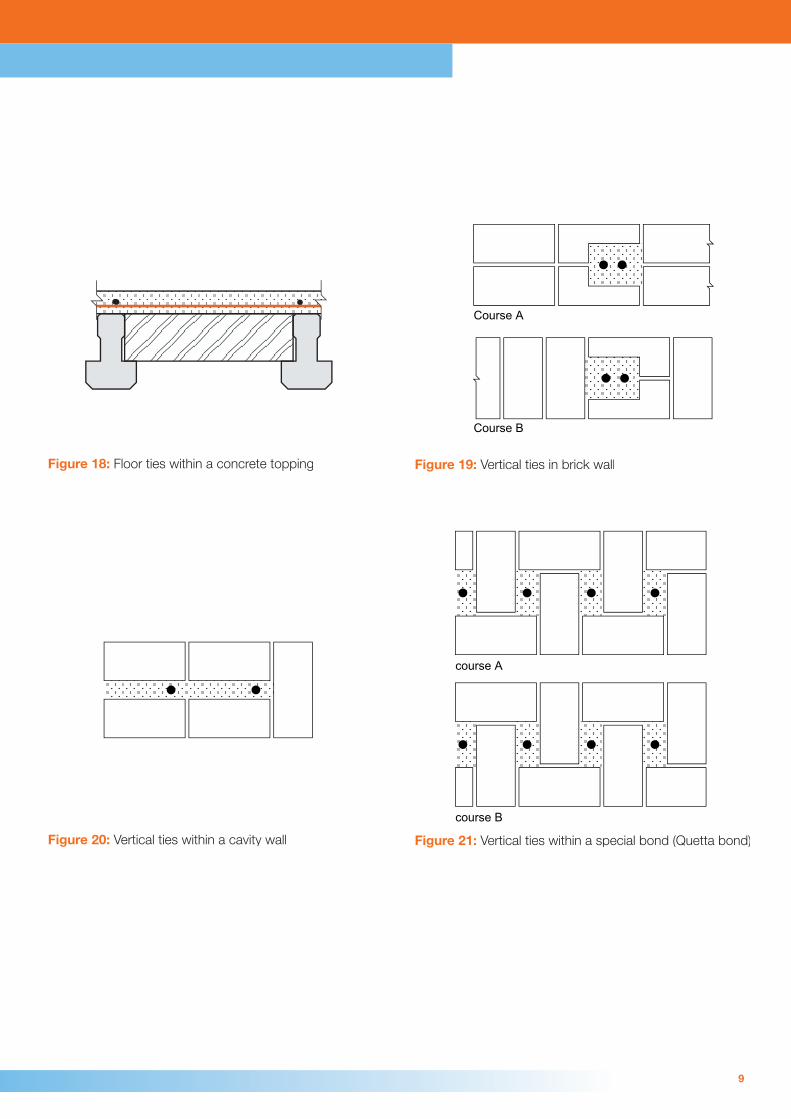
Figure 18: Floor ties within a concrete topping
Course A
Course B
Figure 19: Vertical ties in brick wall
Figure 20: Vertical ties within a cavity wall
course A
course B
Figure 21: Vertical ties within a special bond (Quetta bond)
9

course A
course B
Figure 22: Vertical ties within hollow concrete blocks
Insteadof
Alternativespan
Wall considered tobe removed
Wall considered tobe removed
originalspan
originalspan
Figure 23: Floor alternative spanning paths
10

Figure 24: Catenary concept for the removal of a wall Figure 25: Cantilever approach to removal of a length of wall
Wall spansover opening
Opening
Figure 26: Wall spanning over a section considered removed
11

References:
Guidance on Robustness and Provision against Accidental Actions. BRE Report 200682.
Calibration of proposed revised guidance on meeting compliance with the requirements of Building Regulation A3. http://www.odpm.gov.uk
New Approach to disproportionate collapse. Stuart Alexander. The Structural Engineer, 7th December 2004.
Revised Part A of the Building regulations. Geoff Harding. The Structural Engineer, 18th January 2005.
‘NHBC Technical Guidance Note: The Building Regulations 2004 edition. Requirement A3. Disproportionate collapse’. http://www.nhbc.co.uk
12


![Collapse Analysis of Masonry Arch Bridgescussed [11, 12]. Full-scale bridges are tested to their collapse with comparison to the nite element plane stress analysis. A thinning method](https://static.fdocuments.in/doc/165x107/60e4c165c419173e307c2f45/collapse-analysis-of-masonry-arch-cussed-11-12-full-scale-bridges-are-tested.jpg)
