Masonry Design - Facultyfaculty.arch.tamu.edu/.../4210/NS27-1msnrydesign.pdf · 2014-07-21 · ARCH...
7
ARCH 614 Note Set 27.1 S2014abn 1 Masonry Design Notation: A = name for area A n = net area, equal to the gross area subtracting any reinforcement A nv = net shear area of masonry A s = area of steel reinforcement in masonry design A st = area of steel reinforcement in masonry column design ACI = American Concrete Institute ASCE = American Society of Civil Engineers b = width, often cross-sectional C = name for a compression force C m = compression force in the masonry for masonry design CMU = shorthand for concrete masonry unit d = effective depth from the top of a reinforced masonry beam to the centroid of the tensile steel e = eccentric distance of application of a force (P) from the centroid of a cross section f a = axial stress f b = bending stress m f = calculated compressive stress in masonry m f = masonry design compressive stress s f = stress in the steel reinforcement for masonry design f v = shear stress F a = allowable axial stress F b = allowable bending stress F s = allowable tensile stress in reinforcement for masonry design F t = allowable tensile stress F v = allowable shear stress F vm = allowable shear stress of the masonry F vs = allowable shear stress of the shear reinforcement h = name for height = effective height of a wall or column I x = moment of inertia with respect to an x-axis j = multiplier by effective depth of masonry section for moment arm, jd k = multiplier by effective depth of masonry section for neutral axis, kd L = name for length or span length M = internal bending moment = type of masonry mortar M m = moment capacity of a reinforced masonry beam governed by steel stress M s = moment capacity of a reinforced masonry beam governed by masonry stress MSJC= Masonry Structural Joint Council n = modulus of elasticity transformation coefficient for steel to masonry n.a. = shorthand for neutral axis (N.A.) N = type of masonry mortar NCMA = National Concrete Masonry Association O = type of masonry mortar P = name for axial force vector P a = allowable axial load in columns r = radius of gyration S = section modulus = type of masonry mortar S x = section modulus with respect to an x-axis t = name for thickness T = name for a tension force T s = tension force in the steel reinforcement for masonry design TMS = The Masonry Society w = name for distributed load 1 = coefficient for determining stress block height, c, in masonry LRFD design m = strain in the masonry s = strain in the steel = reinforcement ratio in masonry design
Transcript of Masonry Design - Facultyfaculty.arch.tamu.edu/.../4210/NS27-1msnrydesign.pdf · 2014-07-21 · ARCH...

ARCH 614 Note Set 27.1 S2014abn
1
Masonry Design
Notation:
A = name for area
An = net area, equal to the gross area
subtracting any reinforcement
Anv = net shear area of masonry
As = area of steel reinforcement in
masonry design
Ast = area of steel reinforcement in
masonry column design
ACI = American Concrete Institute
ASCE = American Society of Civil Engineers
b = width, often cross-sectional
C = name for a compression force
Cm = compression force in the masonry
for masonry design
CMU = shorthand for concrete masonry unit
d = effective depth from the top of a
reinforced masonry beam to the
centroid of the tensile steel
e = eccentric distance of application of a
force (P) from the centroid of a cross
section
fa = axial stress
fb = bending stress
mf = calculated compressive stress in
masonry
mf = masonry design compressive stress
sf = stress in the steel reinforcement for
masonry design
fv = shear stress
Fa = allowable axial stress
Fb = allowable bending stress
Fs = allowable tensile stress in
reinforcement for masonry design
Ft = allowable tensile stress
Fv = allowable shear stress
Fvm = allowable shear stress of the
masonry
Fvs = allowable shear stress of the shear
reinforcement
h = name for height
= effective height of a wall or column
Ix = moment of inertia with respect to an
x-axis
j = multiplier by effective depth of
masonry section for moment arm, jd
k = multiplier by effective depth of
masonry section for neutral axis, kd
L = name for length or span length
M = internal bending moment
= type of masonry mortar
Mm = moment capacity of a reinforced
masonry beam governed by steel
stress
Ms = moment capacity of a reinforced
masonry beam governed by masonry
stress
MSJC = Masonry Structural Joint Council
n = modulus of elasticity transformation
coefficient for steel to masonry
n.a. = shorthand for neutral axis (N.A.)
N = type of masonry mortar
NCMA = National Concrete Masonry
Association
O = type of masonry mortar
P = name for axial force vector
Pa = allowable axial load in columns
r = radius of gyration
S = section modulus
= type of masonry mortar
Sx = section modulus with respect to an
x-axis
t = name for thickness
T = name for a tension force
Ts = tension force in the steel
reinforcement for masonry design
TMS = The Masonry Society
w = name for distributed load
1 = coefficient for determining stress
block height, c, in masonry LRFD
design
m = strain in the masonry
s = strain in the steel
= reinforcement ratio in masonry
design

ARCH 614 Note Set 27.1 S2014abn
2
Reinforced Masonry Design
Structural design standards for reinforced masonry are established by the Masonry Standards
Joint Committee consisting of ACI, ASCE and The Masonry Society (TMS), and presents
allowable stress design as well as limit state (strength) design.
Materials
f’m = masonry prism compressive strength from testing
Reinforcing steel grades are the same as those used for reinforced concrete beams.
Units can be brick, concrete or stone.
Mortar consists of masonry cement, lime, sand, and water. Grades are named from the word
MASONWORK, with average strengths of 2500psi, 1800 psi, 750 psi, 350 psi, and 75 psi,
respectively.
Grout is a flowable mortar, usually with a high amount of water to cement material. It is used to
fill voids and bond reinforcement.
Allowable Stress Design
For unreinforced masonry, like masonry walls, tension stresses are allowed in flexure. Masonry
walls typically see compression stresses too.
For reinforced masonry, the steel is presumed to resist all tensile stresses and the tension in the
masonry is ignored.
Factors of Safety are applied to the limit stresses for allowable stress values:
bending (unreinforced) Fb = 1/3 mf
bending (reinforced) Fb = 0.45 mf
bending (tension/unreinforced) table 2.2.3.2
beam shear (unreinforced for flexure) Fv = 1.5 mf 120 psi
beam shear (reinforced) – M/(Vd) 0.25 Fv = 3.0 mf
beam shear (reinforced) – M/(Vd) 1.0 Fv = 2.0 mf
Grades 40 or 50 reinforcement Fs = 20 ksi
Grades 60 reinforcement Fs = 32 ksi
Wire joint reinforcement Fs = 30 ksi
where f’’m = specified compressive strength of masonry

ARCH 614 Note Set 27.1 S2014abn
3
Internal Equilibrium for Bending
Cm = compression in the masonry = stress x area = 2
)(kdbfm
Ts = tension in steel = stress x area = Asfs
Cm = Ts and •
Mm = Ts(d-kd/3) = Ts(jd)
Ms =Cm(jd)
where
fm = compressive stress in the masonry from flexure
fs = tensile stress in the steel reinforcement
kd = the height to the neutral axis
b = width of stress area
d = effective depth of section = depth to n.a. of reinforcement
jd = moment arm from tension force to compression force
As = area of steel
n = Es/Em used to transform steel to equivalent area of masonry for elastic stresses
= reinforcement ratio
Criteria for Beam Design
For flexure design:
jkbdf.jdkd
bfM mmm
2502
or ssss jfρbdjdfAM 2
The design is adequate when bb Ff in the masonry and ss Ff .in the steel.
Shear stress is determined by fv = V/Anv where Anv is net shear area. Shear strength is determined
from the shear capacity of the masonry and the stirrups: Fv = Fvm + Fvs. Stirrup spacings are
limited to d/2 but not to exceed 48 in.
where:
n
mvmA
P.f
Vd
M..F 25075104
2
1
where M/(Vd) is positive and cannot exceed 1.0
sA
dFA.F
nv
svvs 50
BIA Teknote 17 series
grout
unit
t
d n.a.
STRAIN STRESS
A s
f m
kd
s T s = A s f s f s /n
m C m =f m b(kd)/2
jd
bd
A s
M
2
kdbffA mss F=0:
b
(Fv = 3.0 mf when M/(Vd) 0.25 )
(Fv = 2.0 mf when M(Vd) 1.0.) Values can be linearly interpolated.
ARCH 614 Note Set 27.1 S2014abn
4
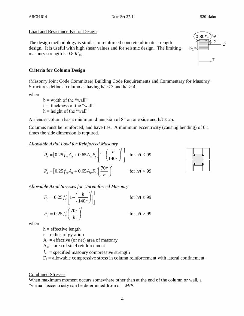
Load and Resistance Factor Design
The design methodology is similar to reinforced concrete ultimate strength
design. It is useful with high shear values and for seismic design. The limiting
masonry strength is 0.80f’m.
Criteria for Column Design
(Masonry Joint Code Committee) Building Code Requirements and Commentary for Masonry
Structures define a column as having b/t < 3 and h/t > 4.
where
b = width of the “wall”
t = thickness of the “wall”
h = height of the “wall”
A slender column has a minimum dimension of 8” on one side and h/t 25.
Columns must be reinforced, and have ties. A minimum eccentricity (causing bending) of 0.1
times the side dimension is required.
Allowable Axial Load for Reinforced Masonry
2
140165.025.0
r
hFAAfP sstnma for h/t 99
2
7065.025.0
h
rFAAfP sstnma for h/t > 99
Allowable Axial Stresses for Unreinforced Masonry
2
140125.0
r
hfF ma for h/t 99
270
25.0
h
rfF ma for h/t > 99
where
h = effective length
r = radius of gyration
An = effective (or net) area of masonry
Ast = area of steel reinforcement
mf = specified masonry compressive strength
Fs = allowable compressive stress in column reinforcement with lateral confinement.
Combined Stresses
When maximum moment occurs somewhere other than at the end of the column or wall, a
“virtual” eccentricity can be determined from e = M/P.
T
1c
0.80f’m
C2
c1

ARCH 614 Note Set 27.1 S2014abn
5
Masonry Columns and Walls
There are no modification factors, but in addition to satisfying 0.1b
b
a
a
F
f
F
f, the tensile stress
cannot exceed the allowable: tab Fff or the compressive stress exceed allowable for
reinforced masonry: bba Fff provided aa Ff .

ARCH 614 Note Set 27.1 S2014abn
6
Example 1
Determine if the unreinforced CMU wall can sustain its loads
with the wind. Specify a mortar type and unit strength per
MSJC.
99140
1250
2
r
hfor
r
hf.F
ma
9970
250
2
r
hfor
h
rf.F
ma
01.F
f
F
f
b
b
a
a mbfF 3
1
mmaf.
in.
inf.Fso.
in.
)in(ft
r
h
2240
213140
12121250944
213
12122
Moment distribution
from eccentricity
Moment distribution from
distributed wind load
Mmax = Pe
M = Pe/2 Mmax = wL2/8
S
Mf
b
A
Pf
a
(1 ftkips/ft2) (ft) (in/ft)
psi
1056 psi
fb 1/3f’m
f’m 154/(1/3) = 462 psi
f’m = 1056 psi (governs)
25 psi
14-1B:
1;
3.21”
psiin
)(kf
klb
a133
30
100042
0.224 1038 psi

ARCH 614 Note Set 27.1 S2014abn
7