MASONRY ANCHORS INTRODUCTION 4-21 · MASONRY ANCHORS INTRODUCTION 4-21 SLEEVE ANCHORS 22-40...
115
Transcript of MASONRY ANCHORS INTRODUCTION 4-21 · MASONRY ANCHORS INTRODUCTION 4-21 SLEEVE ANCHORS 22-40...
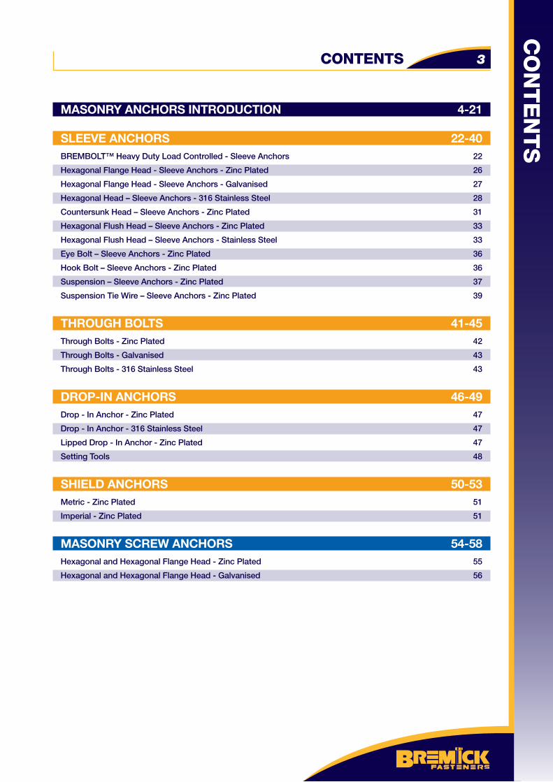
MASONRY ANCHORS INTRODUCTION 4-21
SLEEVE ANCHORS 22-40BREMBOLT™ Heavy Duty Load Controlled - Sleeve Anchors 22
Hexagonal Flange Head - Sleeve Anchors - Zinc Plated 26
Hexagonal Flange Head - Sleeve Anchors - Galvanised 27
Hexagonal Head – Sleeve Anchors - 316 Stainless Steel 28
Countersunk Head – Sleeve Anchors - Zinc Plated 31
Hexagonal Flush Head – Sleeve Anchors - Zinc Plated 33
Hexagonal Flush Head – Sleeve Anchors - Stainless Steel 33
Eye Bolt – Sleeve Anchors - Zinc Plated 36
Hook Bolt – Sleeve Anchors - Zinc Plated 36
Suspension – Sleeve Anchors - Zinc Plated 37
Suspension Tie Wire – Sleeve Anchors - Zinc Plated 39
THROUGH BOLTS 41-45Through Bolts - Zinc Plated 42
Through Bolts - Galvanised 43
Through Bolts - 316 Stainless Steel 43
DROP-IN ANCHORS 46-49Drop - In Anchor - Zinc Plated 47
Drop - In Anchor - 316 Stainless Steel 47
Lipped Drop - In Anchor - Zinc Plated 47
Setting Tools 48
SHIELD ANCHORS 50-53Metric - Zinc Plated 51
Imperial - Zinc Plated 51
MASONRY SCREW ANCHORS 54-58Hexagonal and Hexagonal Flange Head - Zinc Plated 55
Hexagonal and Hexagonal Flange Head - Galvanised 56
CONTENTS 3
CO
NT
EN
TS
CO
NT
EN
TS
CONTENTS4
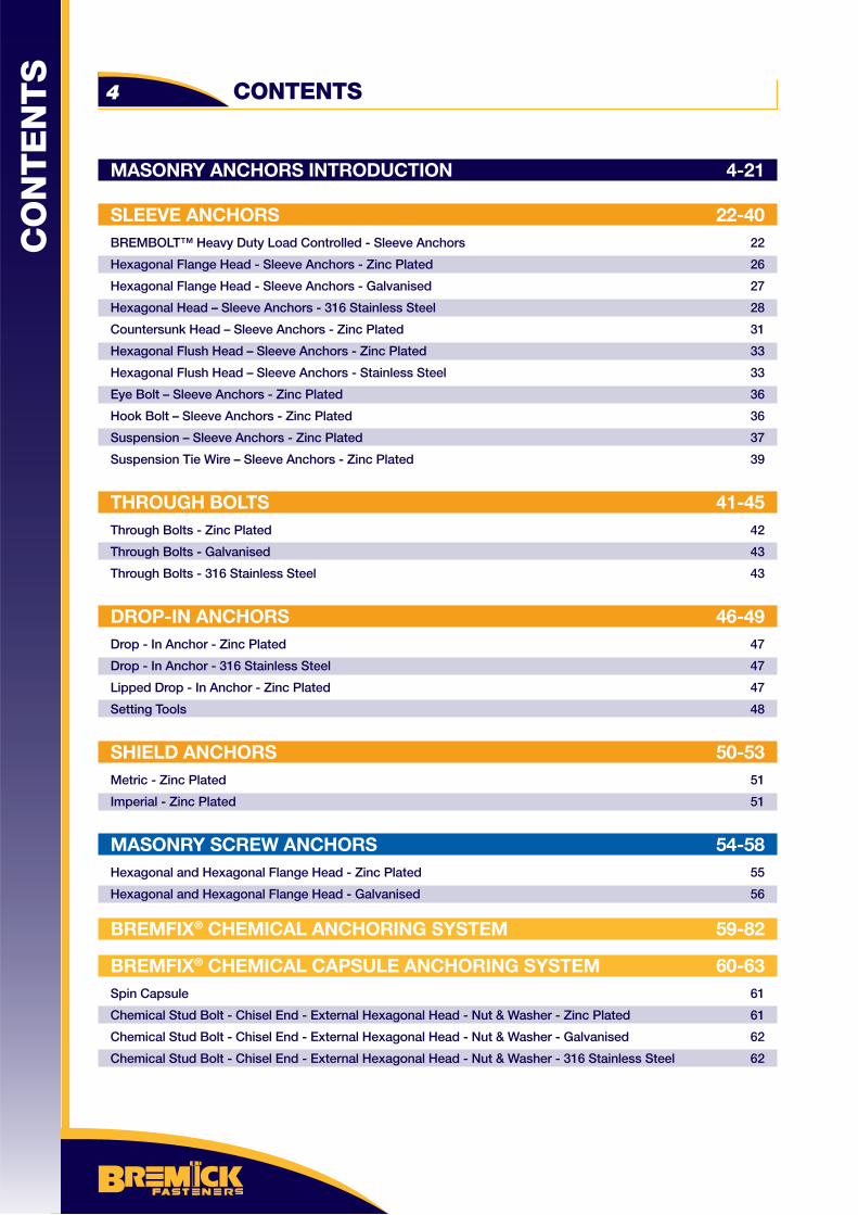
MASONRY ANCHORS INTRODUCTION 4-21
SLEEVE ANCHORS 22-40BREMBOLT™ Heavy Duty Load Controlled - Sleeve Anchors 22
Hexagonal Flange Head - Sleeve Anchors - Zinc Plated 26
Hexagonal Flange Head - Sleeve Anchors - Galvanised 27
Hexagonal Head – Sleeve Anchors - 316 Stainless Steel 28
Countersunk Head – Sleeve Anchors - Zinc Plated 31
Hexagonal Flush Head – Sleeve Anchors - Zinc Plated 33
Hexagonal Flush Head – Sleeve Anchors - Stainless Steel 33
Eye Bolt – Sleeve Anchors - Zinc Plated 36
Hook Bolt – Sleeve Anchors - Zinc Plated 36
Suspension – Sleeve Anchors - Zinc Plated 37
Suspension Tie Wire – Sleeve Anchors - Zinc Plated 39
THROUGH BOLTS 41-45Through Bolts - Zinc Plated 42
Through Bolts - Galvanised 43
Through Bolts - 316 Stainless Steel 43
DROP-IN ANCHORS 46-49Drop - In Anchor - Zinc Plated 47
Drop - In Anchor - 316 Stainless Steel 47
Lipped Drop - In Anchor - Zinc Plated 47
Setting Tools 48
SHIELD ANCHORS 50-53Metric - Zinc Plated 51
Imperial - Zinc Plated 51
MASONRY SCREW ANCHORS 54-58Hexagonal and Hexagonal Flange Head - Zinc Plated 55
Hexagonal and Hexagonal Flange Head - Galvanised 56
BREMFIX® CHEMICAL ANCHORING SYSTEM 59-82
BREMFIX® CHEMICAL CAPSULE ANCHORING SYSTEM 60-63Spin Capsule 61
Chemical Stud Bolt - Chisel End - External Hexagonal Head - Nut & Washer - Zinc Plated 61
Chemical Stud Bolt - Chisel End - External Hexagonal Head - Nut & Washer - Galvanised 62
Chemical Stud Bolt - Chisel End - External Hexagonal Head - Nut & Washer - 316 Stainless Steel 62
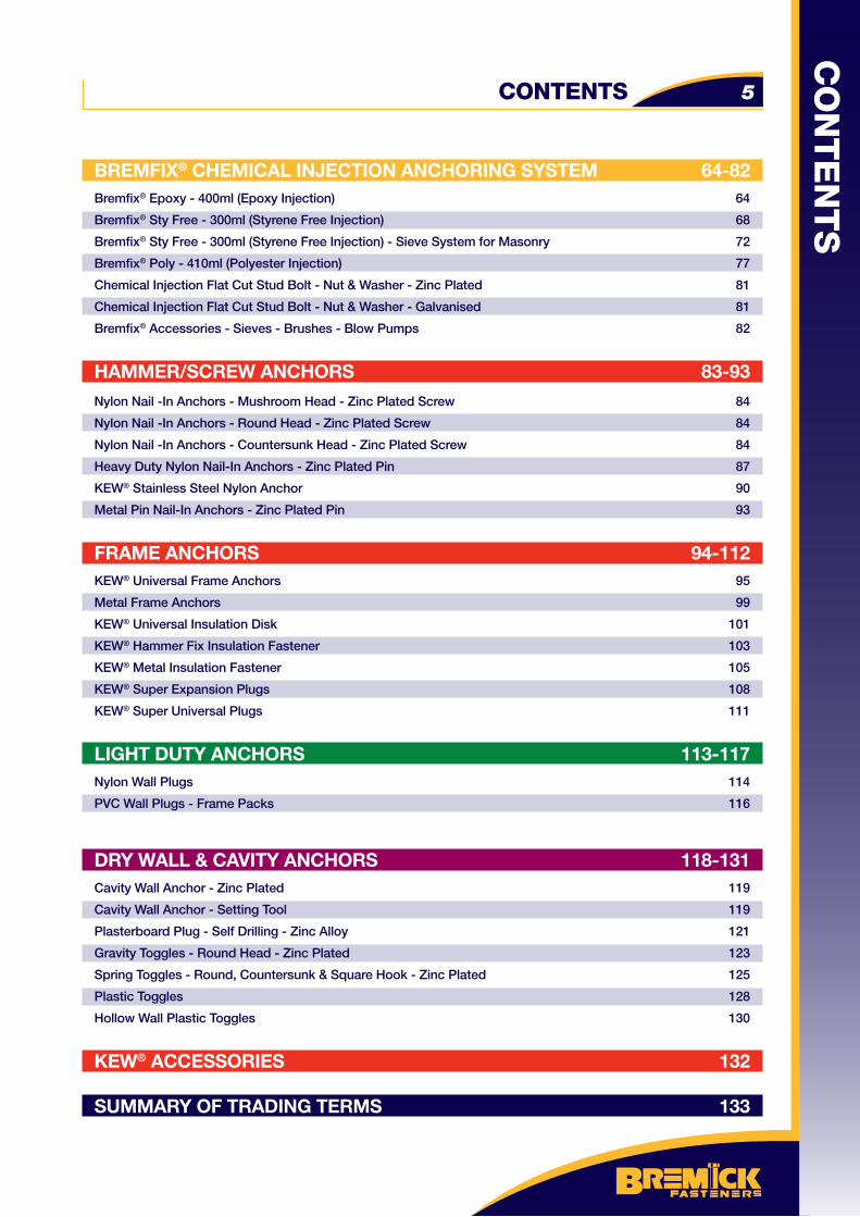
BREMFIX® CHEMICAL INJECTION ANCHORING SYSTEM 64-82Bremfi x® Epoxy - 400ml (Epoxy Injection) 64
Bremfi x® Sty Free - 300ml (Styrene Free Injection) 68
Bremfi x® Sty Free - 300ml (Styrene Free Injection) - Sieve System for Masonry 72
Bremfi x® Poly - 410ml (Polyester Injection) 77
Chemical Injection Flat Cut Stud Bolt - Nut & Washer - Zinc Plated 81
Chemical Injection Flat Cut Stud Bolt - Nut & Washer - Galvanised 81
Bremfi x® Accessories - Sieves - Brushes - Blow Pumps 82
HAMMER/SCREW ANCHORS 83-93Nylon Nail -In Anchors - Mushroom Head - Zinc Plated Screw 84
Nylon Nail -In Anchors - Round Head - Zinc Plated Screw 84
Nylon Nail -In Anchors - Countersunk Head - Zinc Plated Screw 84
Heavy Duty Nylon Nail-In Anchors - Zinc Plated Pin 87
KEW® Stainless Steel Nylon Anchor 90
Metal Pin Nail-In Anchors - Zinc Plated Pin 93
FRAME ANCHORS 94-112KEW® Universal Frame Anchors 95
Metal Frame Anchors 99
KEW® Universal Insulation Disk 101
KEW® Hammer Fix Insulation Fastener 103
KEW® Metal Insulation Fastener 105
KEW® Super Expansion Plugs 108
KEW® Super Universal Plugs 111
LIGHT DUTY ANCHORS 113-117Nylon Wall Plugs 114
PVC Wall Plugs - Frame Packs 116
DRY WALL & CAVITY ANCHORS 118-131Cavity Wall Anchor - Zinc Plated 119
Cavity Wall Anchor - Setting Tool 119
Plasterboard Plug - Self Drilling - Zinc Alloy 121
Gravity Toggles - Round Head - Zinc Plated 123
Spring Toggles - Round, Countersunk & Square Hook - Zinc Plated 125
Plastic Toggles 128
Hollow Wall Plastic Toggles 130
KEW® ACCESSORIES 132
SUMMARY OF TRADING TERMS 133
CONTENTS 5
CO
NT
EN
TS
APPLICATIONS
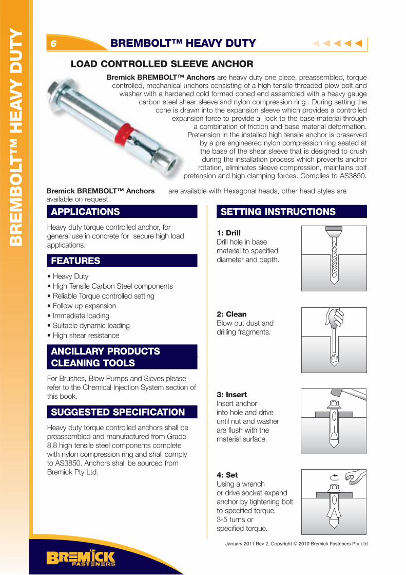
Heavy duty torque controlled anchor, for general use in concrete for secure high load applications.
FEATURES
• Heavy Duty• High Tensile Carbon Steel components• Reliable Torque controlled setting• Follow up expansion• Immediate loading• Suitable dynamic loading• High shear resistance
ANCILLARY PRODUCTSCLEANING TOOLS
For Brushes, Blow Pumps and Sieves please refer to the Chemical Injection System section of this book.
SUGGESTED SPECIFICATION
Heavy duty torque controlled anchors shall be preassembled and manufactured from Grade 8.8 high tensile steel components complete with nylon compression ring and shall comply to AS3850. Anchors shall be sourced from Bremick Pty Ltd.
SETTING INSTRUCTIONS
1: DrillDrill hole in base material to specifieddiameter and depth.
2: CleanBlow out dust anddrilling fragments.
3: InsertInsert anchorinto hole and driveuntil nut and washerare flush with the material surface.
4: SetUsing a wrenchor drive socket expand anchor by tightening boltto specified torque.3-5 turns or specified torque.
Bremick BREMBOLT™ Anchors are heavy duty one piece, preassembled, torque controlled, mechanical anchors consisting of a high tensile threaded plow bolt and
washer with a hardened cold formed coned end assembled with a heavy gauge carbon steel shear sleeve and nylon compression ring . During setting the
cone is drawn into the expansion sleeve which provides a controlled expansion force to provide a lock to the base material through
a combination of friction and base material deformation. Pretension in the installed high tensile anchor is preserved
by a pre engineered nylon compression ring seated at the base of the shear sleeve that is designed to crush during the installation process which prevents anchor
rotation, eliminates sleeve compression, maintains bolt pretension and high clamping forces. Complies to AS3850.p
Bremick BREMBOLTcontrolled, mechanical a
washer with a hardencarbon steel sh
cone is drexpa
BR
EM
BO
LT™
HE
AV
Y D
UT
Y
BREMBOLT™ HEAVY DUTY
Bremick BREMBOLT™ Anchors are available with Hexagonal heads, other head styles are available on request.
6
LOAD CONTROLLED SLEEVE ANCHOR
January 2011 Rev 2, Copyright © 2010 Bremick Fasteners Pty Ltd
SLE
EV
E A
NC
HO
RS
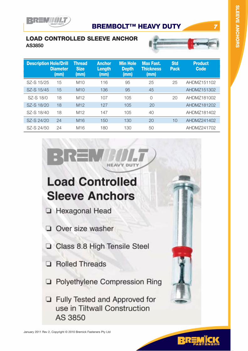
SZ-S 15/25 15 M10 116 95 25 25 AHDMZ151102
SZ-S 15/45 15 M10 136 95 45 AHDMZ151302
SZ-S 18/0 18 M12 107 105 0 20 AHDMZ181002
SZ-S 18/20 18 M12 127 105 20 AHDMZ181202
SZ-S 18/40 18 M12 147 105 40 AHDMZ181402
SZ-S 24/20 24 M16 150 130 20 10 AHDMZ241402
SZ-S 24/50 24 M16 180 130 50 AHDMZ241702
Description Hole/Drill Thread Anchor Min Hole Max Fast. Std Product Diameter Size Length Depth Thickness Pack Code (mm) (mm) (mm) (mm) (mm)
LOAD CONTROLLED SLEEVE ANCHORAS3850
BREMBOLT™ HEAVY DUTY 7
January 2011 Rev 2, Copyright © 2010 Bremick Fasteners Pty Ltd
SLE
EV
E A
NC
HO
RS
BREMBOLT™ HEAVY DUTY8
LOAD CONTROLLED SLEEVE ANCHORSHEXAGONAL HEAD - ZINC PLATED
SZ-S 15/25 15 M10 116
SZ-S 15/45 15 M10 136
SZ-S 18/0 18 M12 107
SZ-S 18/20 18 M12 127
SZ-S 18/40 18 M12 147
SZ-S 24/20 24 M16 150
SZ-S 24/50 24 M16 180
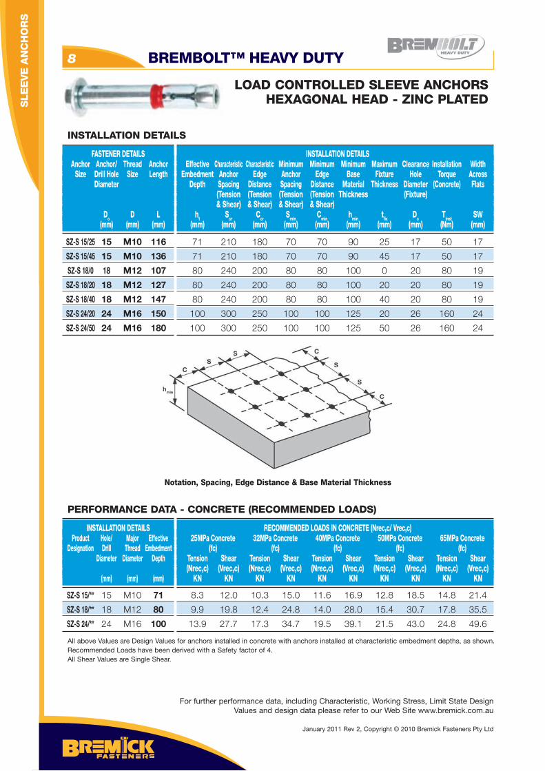
FASTENER DETAILS Anchor Anchor/ Thread Anchor Size Drill Hole Size Length Diameter
Do D L (mm) (mm) (mm)
INSTALLATION DETAILS Effective Characteristic Characteristic Minimum Minimum Minimum Maximum Clearance Installation Width Embedment Anchor Edge Anchor Edge Base Fixture Hole Torque Across Depth Spacing Distance Spacing Distance Material Thickness Diameter (Concrete) Flats (Tension (Tension (Tension (Tension Thickness (Fixture) & Shear) & Shear) & Shear) & Shear) ht Scr Ccr Smin Cmin hmin tfi x Dc Tinst SW (mm) (mm) (mm) (mm) (mm) (mm) (mm) (mm) (Nm) (mm)
INSTALLATION DETAILS
71 210 180 70 70 90 25 17 50 17
71 210 180 70 70 90 45 17 50 17
80 240 200 80 80 100 0 20 80 19
80 240 200 80 80 100 20 20 80 19
80 240 200 80 80 100 40 20 80 19
100 300 250 100 100 125 20 26 160 24
100 300 250 100 100 125 50 26 160 24
Notation, Spacing, Edge Distance & Base Material Thickness
SZ-S 15/** 15 M10 71
SZ-S 18/** 18 M12 80
SZ-S 24/** 24 M16 100
INSTALLATION DETAILS Product Hole/ Major Effective Designation Drill Thread Embedment Diameter Diameter Depth (mm) (mm) (mm)
RECOMMENDED LOADS IN CONCRETE (Nrec,c/ Vrec,c) 25MPa Concrete 32MPa Concrete 40MPa Concrete 50MPa Concrete 65MPa Concrete (fc) (fc) (fc) (fc) (fc) Tension Shear Tension Shear Tension Shear Tension Shear Tension Shear (Nrec,c) (Vrec,c) (Nrec,c) (Vrec,c) (Nrec,c) (Vrec,c) (Nrec,c) (Vrec,c) (Nrec,c) (Vrec,c) KN KN KN KN KN KN KN KN KN KN
8.3 12.0 10.3 15.0 11.6 16.9 12.8 18.5 14.8 21.4
9.9 19.8 12.4 24.8 14.0 28.0 15.4 30.7 17.8 35.5
13.9 27.7 17.3 34.7 19.5 39.1 21.5 43.0 24.8 49.6
All above Values are Design Values for anchors installed in concrete with anchors installed at characteristic embedment depths, as shown. Recommended Loads have been derived with a Safety factor of 4.All Shear Values are Single Shear.
PERFORMANCE DATA - CONCRETE (RECOMMENDED LOADS)
For further performance data, including Characteristic, Working Stress, Limit State Design Values and design data please refer to our Web Site www.bremick.com.au
January 2011 Rev 2, Copyright © 2010 Bremick Fasteners Pty Ltd
SLE
EV
E A
NC
HO
RS
APPLICATIONS
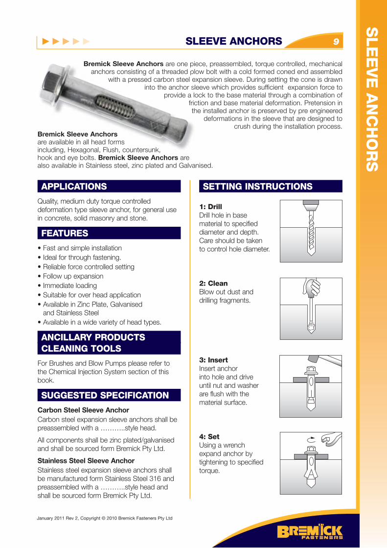
Quality, medium duty torque controlled deformation type sleeve anchor, for general use in concrete, solid masonry and stone.
FEATURES
• Fast and simple installation • Ideal for through fastening.• Reliable force controlled setting• Follow up expansion• Immediate loading• Suitable for over head application• Available in Zinc Plate, Galvanised and Stainless Steel• Available in a wide variety of head types.
ANCILLARY PRODUCTSCLEANING TOOLS
For Brushes and Blow Pumps please refer to the Chemical Injection System section of this book.
SUGGESTED SPECIFICATION
Carbon Steel Sleeve AnchorCarbon steel expansion sleeve anchors shall be preassembled with a ………..style head.
All components shall be zinc plated/galvanised and shall be sourced form Bremick Pty Ltd.
Stainless Steel Sleeve AnchorStainless steel expansion sleeve anchors shall be manufactured form Stainless Steel 316 and preassembled with a ………..style head and shall be sourced form Bremick Pty Ltd.
SETTING INSTRUCTIONS
1: DrillDrill hole in base material to specifieddiameter and depth.Care should be takento control hole diameter.
2: CleanBlow out dust anddrilling fragments.
3: InsertInsert anchorinto hole and driveuntil nut and washerare flush with the material surface.
4: SetUsing a wrenchexpand anchor bytightening to specifiedtorque.
Bremick Sleeve Anchors are one piece, preassembled, torque controlled, mechanical anchors consisting of a threaded plow bolt with a cold formed coned end assembled
with a pressed carbon steel expansion sleeve. During setting the cone is drawn into the anchor sleeve which provides sufficient expansion force to
provide a lock to the base material through a combination of friction and base material deformation. Pretension in the installed anchor is preserved by pre engineered
deformations in the sleeve that are designed to crush during the installation process.
Bremick Sleeve Anchors are available in all head forms including, Hexagonal, Flush, countersunk, hook and eye bolts. Bremick Sleeve Anchors are also available in Stainless steel, zinc plated and Galvanised.
Bremick Sleeve Anchors are oneanchors consisting of a threaded p
with a pressed carbon steel e into the anchor s
provide a lofricth
remick Sleeve Anchorse available in all head forms luding Hexagonal Flush countersunk
SLEEVE ANCHORS 9
January 2011 Rev 2, Copyright © 2010 Bremick Fasteners Pty Ltd
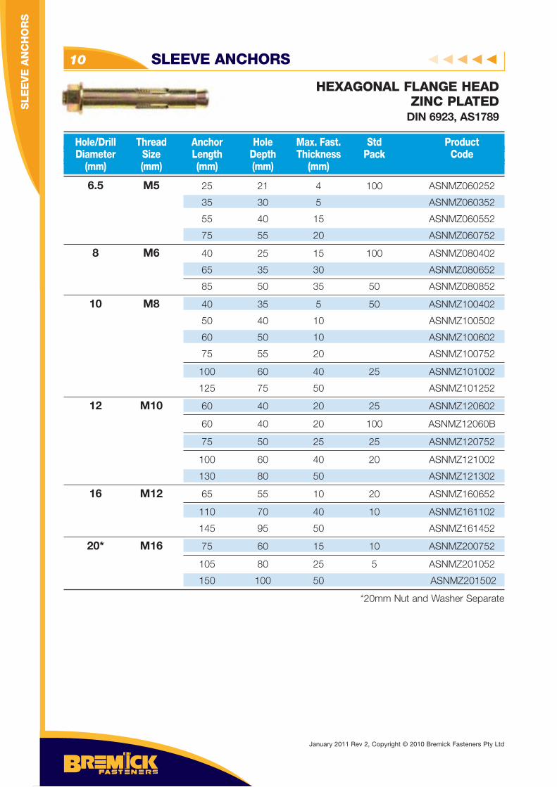
6.5 M5 25 21 4 100 ASNMZ060252
35 30 5 ASNMZ060352
55 40 15 ASNMZ060552
75 55 20 ASNMZ060752
8 M6 40 25 15 100 ASNMZ080402
65 35 30 ASNMZ080652
85 50 35 50 ASNMZ080852
10 M8 40 35 5 50 ASNMZ100402
50 40 10 ASNMZ100502
60 50 10 ASNMZ100602
75 55 20 ASNMZ100752
100 60 40 25 ASNMZ101002
125 75 50 ASNMZ101252
12 M10 60 40 20 25 ASNMZ120602
60 40 20 100 ASNMZ12060B
75 50 25 25 ASNMZ120752
100 60 40 20 ASNMZ121002
130 80 50 ASNMZ121302
16 M12 65 55 10 20 ASNMZ160652
110 70 40 10 ASNMZ161102
145 95 50 ASNMZ161452
20* M16 75 60 15 10 ASNMZ200752
105 80 25 5 ASNMZ201052
150 100 50 ASNMZ201502
*20mm Nut and Washer Separate
Hole/Drill Thread Anchor Hole Max. Fast. Std Product Diameter Size Length Depth Thickness Pack Code (mm) (mm) (mm) (mm) (mm)
HEXAGONAL FLANGE HEADZINC PLATED
DIN 6923, AS1789
SLEEVE ANCHORS10
January 2011 Rev 2, Copyright © 2010 Bremick Fasteners Pty Ltd
SLE
EV
E A
NC
HO
RS
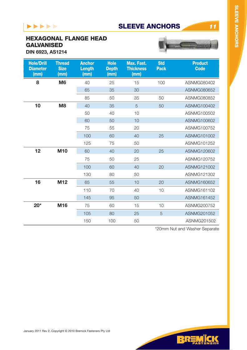
SLEEVE ANCHORS 11
HEXAGONAL FLANGE HEADGALVANISEDDIN 6923, AS1214
8 M6 40 25 15 100 ASNMG080402
65 35 30 ASNMG080652
85 50 35 50 ASNMG080852
10 M8 40 35 5 50 ASNMG100402
50 40 10 ASNMG100502
60 50 10 ASNMG100602
75 55 20 ASNMG100752
100 60 40 25 ASNMG101002
125 75 50 ASNMG101252
12 M10 60 40 20 25 ASNMG120602
75 50 25 ASNMG120752
100 60 40 20 ASNMG121002
130 80 50 ASNMG121302
16 M12 65 55 10 20 ASNMG160652
110 70 40 10 ASNMG161102
145 95 50 ASNMG161452
20* M16 75 60 15 10 ASNMG200752
105 80 25 5 ASNMG201052
150 100 50 ASNMG201502
*20mm Nut and Washer Separate
Hole/Drill Thread Anchor Hole Max. Fast. Std Product Diameter Size Length Depth Thickness Pack Code (mm) (mm) (mm) (mm) (mm)
SLE
EV
E A
NC
HO
RS
January 2011 Rev 2, Copyright © 2010 Bremick Fasteners Pty Ltd
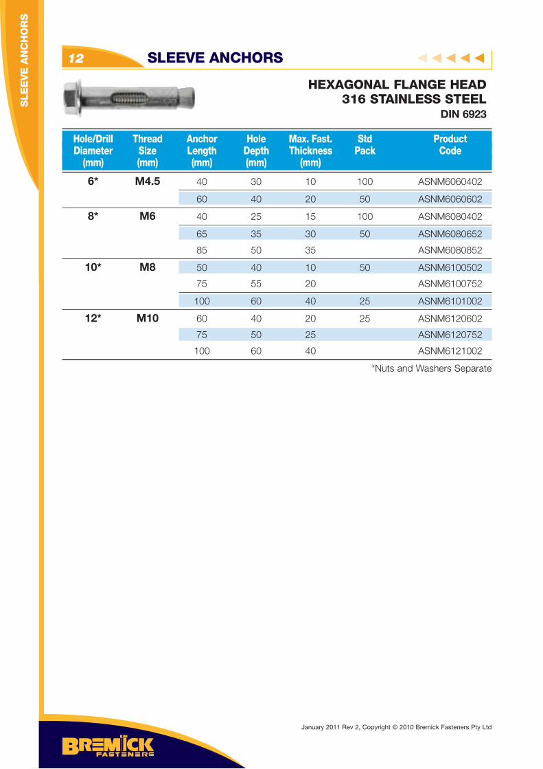
SLEEVE ANCHORS12
HEXAGONAL FLANGE HEAD316 STAINLESS STEEL
DIN 6923
6* M4.5 40 30 10 100 ASNM6060402
60 40 20 50 ASNM6060602
8* M6 40 25 15 100 ASNM6080402
65 35 30 50 ASNM6080652
85 50 35 ASNM6080852
10* M8 50 40 10 50 ASNM6100502
75 55 20 ASNM6100752
100 60 40 25 ASNM6101002
12* M10 60 40 20 25 ASNM6120602
75 50 25 ASNM6120752
100 60 40 ASNM6121002
*Nuts and Washers Separate
Hole/Drill Thread Anchor Hole Max. Fast. Std Product Diameter Size Length Depth Thickness Pack Code (mm) (mm) (mm) (mm) (mm)
January 2011 Rev 2, Copyright © 2010 Bremick Fasteners Pty Ltd
SLE
EV
E A
NC
HO
RS
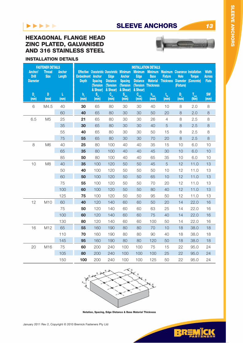
SLEEVE ANCHORS 13
HEXAGONAL FLANGE HEADZINC PLATED, GALVANISED AND 316 STAINLESS STEEL
6 M4.5 40
60
6.5 M5 25
35
55
75
8 M6 40
65
85
10 M8 40
50
60
75
100
125
12 M10 60
75
100
130
16 M12 65
110
145
20 M16 75
105
150
FASTENER DETAILS Anchor/ Thread Anchor Drill Size Length Diameter
Do D L (mm) (mm) (mm)
INSTALLATION DETAILS Effective Characteristic Characteristic Minimum Minimum Minimum Maximum Clearance Installation Width Embedment Anchor Edge Anchor Edge Base Fixture Hole Torque Across Depth Spacing Distance Spacing Distance Material Thickness Diameter (Concrete) Flats (Tension (Tension (Tension (Tension Thickness (Fixture) & Shear) & Shear) & Shear) & Shear) ht Scr Ccr Smin Cmin hmin tfi x Dc Tinst SW (mm) (mm) (mm) (mm) (mm) (mm) (mm) (mm) (Nm) (mm)
INSTALLATION DETAILS
30 65 80 30 30 40 10 8 2.0 8
40 65 80 30 30 50 20 8 2.0 8
21 65 80 30 30 26 4 8 2.5 8
30 65 80 30 30 40 5 8 2.5 8
40 65 80 30 30 50 15 8 2.5 8
55 65 80 30 30 70 20 8 2.5 8
25 80 100 40 40 35 15 10 6.0 10
35 80 100 40 40 45 30 10 6.0 10
50 80 100 40 40 65 35 10 6.0 10
35 100 120 50 50 45 5 12 11.0 13
40 100 120 50 50 50 10 12 11.0 13
50 100 120 50 50 65 10 12 11.0 13
55 100 120 50 50 70 20 12 11.0 13
60 100 120 50 50 80 40 12 11.0 13
75 100 120 50 50 95 50 12 11.0 13
40 120 140 60 60 50 20 14 22.0 16
50 120 140 60 60 63 25 14 22.0 16
60 120 140 60 60 75 40 14 22.0 16
80 120 140 60 60 100 50 14 22.0 16
55 160 190 80 80 70 10 18 38.0 18
70 160 190 80 80 90 40 18 38.0 18
95 160 190 80 80 120 50 18 38.0 18
60 200 240 100 100 75 15 22 95.0 24
80 200 240 100 100 100 25 22 95.0 24
100 200 240 100 100 125 50 22 95.0 24
Notation, Spacing, Edge Distance & Base Material Thickness
SLE
EV
E A
NC
HO
RS
January 2011 Rev 2, Copyright © 2010 Bremick Fasteners Pty Ltd
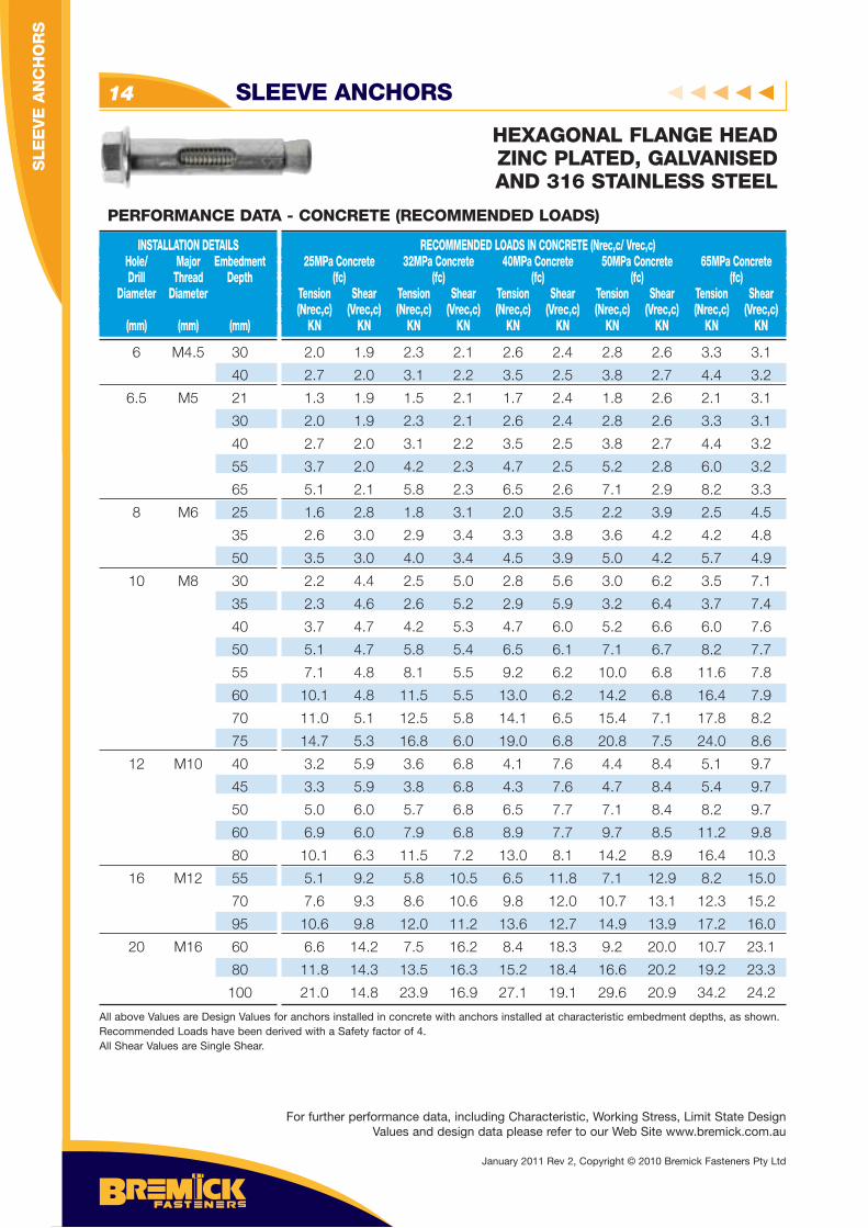
HEXAGONAL FLANGE HEADZINC PLATED, GALVANISED AND 316 STAINLESS STEEL
SLEEVE ANCHORS14
6 M4.5 30
40
6.5 M5 21
30
40
55
65
8 M6 25
35
50
10 M8 30
35
40
50
55
60
70
75
12 M10 40
45
50
60
80
16 M12 55
70
95
20 M16 60
80
100
INSTALLATION DETAILS Hole/ Major Embedment Drill Thread Depth Diameter Diameter (mm) (mm) (mm)
RECOMMENDED LOADS IN CONCRETE (Nrec,c/ Vrec,c) 25MPa Concrete 32MPa Concrete 40MPa Concrete 50MPa Concrete 65MPa Concrete (fc) (fc) (fc) (fc) (fc) Tension Shear Tension Shear Tension Shear Tension Shear Tension Shear (Nrec,c) (Vrec,c) (Nrec,c) (Vrec,c) (Nrec,c) (Vrec,c) (Nrec,c) (Vrec,c) (Nrec,c) (Vrec,c) KN KN KN KN KN KN KN KN KN KN
PERFORMANCE DATA - CONCRETE (RECOMMENDED LOADS)
2.0 1.9 2.3 2.1 2.6 2.4 2.8 2.6 3.3 3.1
2.7 2.0 3.1 2.2 3.5 2.5 3.8 2.7 4.4 3.2
1.3 1.9 1.5 2.1 1.7 2.4 1.8 2.6 2.1 3.1
2.0 1.9 2.3 2.1 2.6 2.4 2.8 2.6 3.3 3.1
2.7 2.0 3.1 2.2 3.5 2.5 3.8 2.7 4.4 3.2
3.7 2.0 4.2 2.3 4.7 2.5 5.2 2.8 6.0 3.2
5.1 2.1 5.8 2.3 6.5 2.6 7.1 2.9 8.2 3.3
1.6 2.8 1.8 3.1 2.0 3.5 2.2 3.9 2.5 4.5
2.6 3.0 2.9 3.4 3.3 3.8 3.6 4.2 4.2 4.8
3.5 3.0 4.0 3.4 4.5 3.9 5.0 4.2 5.7 4.9
2.2 4.4 2.5 5.0 2.8 5.6 3.0 6.2 3.5 7.1
2.3 4.6 2.6 5.2 2.9 5.9 3.2 6.4 3.7 7.4
3.7 4.7 4.2 5.3 4.7 6.0 5.2 6.6 6.0 7.6
5.1 4.7 5.8 5.4 6.5 6.1 7.1 6.7 8.2 7.7
7.1 4.8 8.1 5.5 9.2 6.2 10.0 6.8 11.6 7.8
10.1 4.8 11.5 5.5 13.0 6.2 14.2 6.8 16.4 7.9
11.0 5.1 12.5 5.8 14.1 6.5 15.4 7.1 17.8 8.2
14.7 5.3 16.8 6.0 19.0 6.8 20.8 7.5 24.0 8.6
3.2 5.9 3.6 6.8 4.1 7.6 4.4 8.4 5.1 9.7
3.3 5.9 3.8 6.8 4.3 7.6 4.7 8.4 5.4 9.7
5.0 6.0 5.7 6.8 6.5 7.7 7.1 8.4 8.2 9.7
6.9 6.0 7.9 6.8 8.9 7.7 9.7 8.5 11.2 9.8
10.1 6.3 11.5 7.2 13.0 8.1 14.2 8.9 16.4 10.3
5.1 9.2 5.8 10.5 6.5 11.8 7.1 12.9 8.2 15.0
7.6 9.3 8.6 10.6 9.8 12.0 10.7 13.1 12.3 15.2
10.6 9.8 12.0 11.2 13.6 12.7 14.9 13.9 17.2 16.0
6.6 14.2 7.5 16.2 8.4 18.3 9.2 20.0 10.7 23.1
11.8 14.3 13.5 16.3 15.2 18.4 16.6 20.2 19.2 23.3
21.0 14.8 23.9 16.9 27.1 19.1 29.6 20.9 34.2 24.2
All above Values are Design Values for anchors installed in concrete with anchors installed at characteristic embedment depths, as shown. Recommended Loads have been derived with a Safety factor of 4.All Shear Values are Single Shear.
For further performance data, including Characteristic, Working Stress, Limit State Design Values and design data please refer to our Web Site www.bremick.com.au
January 2011 Rev 2, Copyright © 2010 Bremick Fasteners Pty Ltd
SLE
EV
E A
NC
HO
RS
SLEEVE ANCHORS 15
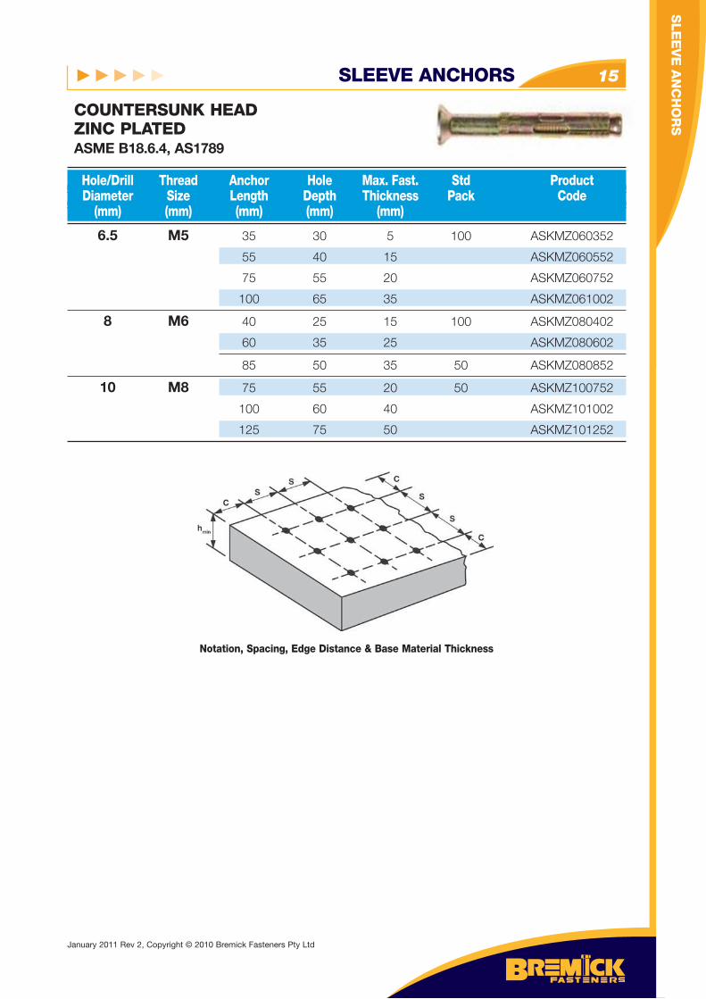
6.5 M5 35 30 5 100 ASKMZ060352
55 40 15 ASKMZ060552
75 55 20 ASKMZ060752
100 65 35 ASKMZ061002
8 M6 40 25 15 100 ASKMZ080402
60 35 25 ASKMZ080602
85 50 35 50 ASKMZ080852
10 M8 75 55 20 50 ASKMZ100752
100 60 40 ASKMZ101002
125 75 50 ASKMZ101252
Hole/Drill Thread Anchor Hole Max. Fast. Std Product Diameter Size Length Depth Thickness Pack Code (mm) (mm) (mm) (mm) (mm)
COUNTERSUNK HEADZINC PLATEDASME B18.6.4, AS1789
Notation, Spacing, Edge Distance & Base Material Thickness
SLE
EV
E A
NC
HO
RS
January 2011 Rev 2, Copyright © 2010 Bremick Fasteners Pty Ltd
SLE
EV
E A
NC
HO
RS
SLEEVE ANCHORS16
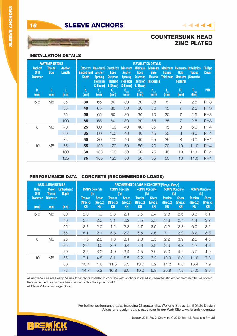
COUNTERSUNK HEADZINC PLATED
6.5 M5 35
55
75
100
8 M6 40
60
85
10 M8 75
100
125
FASTENER DETAILS Anchor/ Thread Anchor Drill Size Length Diameter
Do D L (mm) (mm) (mm)
INSTALLATION DETAILS Effective Characteristic Characteristic Minimum Minimum Minimum Maximum Clearance Installation Phillips Embedment Anchor Edge Anchor Edge Base Fixture Hole Torque Driver Depth Spacing Distance Spacing Distance Material Thickness Diameter (Concrete) (Tension (Tension (Tension (Tension Thickness (Fixture) & Shear) & Shear) & Shear) & Shear) ht Scr Ccr Smin Cmin hmin tfi x Dc Tinst PH# (mm) (mm) (mm) (mm) (mm) (mm) (mm) (mm) (Nm)
INSTALLATION DETAILS
30 65 80 30 30 38 5 7 2.5 PH3
40 65 80 30 30 50 15 7 2.5 PH3
55 65 80 30 30 70 20 7 2.5 PH3
65 65 80 30 30 85 35 7 2.5 PH3
25 80 100 40 40 35 15 8 6.0 PH4
35 80 100 40 40 45 25 8 6.0 PH4
50 80 100 40 40 65 35 8 6.0 PH4
55 100 120 50 50 70 20 10 11.0 PH4
60 100 120 50 50 75 40 10 11.0 PH4
75 100 120 50 50 95 50 10 11.0 PH4
6.5 M5 30
40
55
65
8 M6 25
35
50
10 M8 55
60
75
INSTALLATION DETAILS Hole/ Major Embedment Drill Thread Depth Diameter Diameter (mm) (mm) (mm)
RECOMMENDED LOADS IN CONCRETE (Nrec,c/ Vrec,c) 25MPa Concrete 32MPa Concrete 40MPa Concrete 50MPa Concrete 65MPa Concrete (fc) (fc) (fc) (fc) (fc) Tension Shear Tension Shear Tension Shear Tension Shear Tension Shear (Nrec,c) (Vrec,c) (Nrec,c) (Vrec,c) (Nrec,c) (Vrec,c) (Nrec,c) (Vrec,c) (Nrec,c) (Vrec,c) KN KN KN KN KN KN KN KN KN KN
PERFORMANCE DATA - CONCRETE (RECOMMENDED LOADS)
2.0 1.9 2.3 2.1 2.6 2.4 2.8 2.6 3.3 3.1
2.7 2.0 3.1 2.2 3.5 2.5 3.8 2.7 4.4 3.2
3.7 2.0 4.2 2.3 4.7 2.5 5.2 2.8 6.0 3.2
5.1 2.1 5.8 2.3 6.5 2.6 7.1 2.9 8.2 3.3
1.6 2.8 1.8 3.1 2.0 3.5 2.2 3.9 2.5 4.5
2.6 3.0 2.9 3.4 3.3 3.8 3.6 4.2 4.2 4.8
3.5 3.0 4.0 3.4 4.5 3.9 5.0 4.2 5.7 4.9
7.1 4.8 8.1 5.5 9.2 6.2 10.0 6.8 11.6 7.8
10.1 4.8 11.5 5.5 13.0 6.2 14.2 6.8 16.4 7.9
14.7 5.3 16.8 6.0 19.0 6.8 20.8 7.5 24.0 8.6
All above Values are Design Values for anchors installed in concrete with anchors installed at characteristic embedment depths, as shown. Recommended Loads have been derived with a Safety factor of 4.All Shear Values are Single Shear.
For further performance data, including Characteristic, Working Stress, Limit State Design Values and design data please refer to our Web Site www.bremick.com.au
January 2011 Rev 2, Copyright © 2010 Bremick Fasteners Pty Ltd
SLE
EV
E A
NC
HO
RS
SLEEVE ANCHORS 17
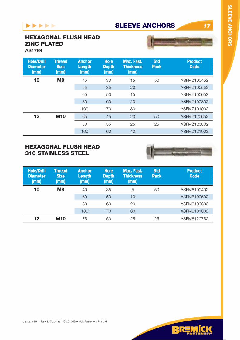
10 M8 45 30 15 50 ASFMZ100452
55 35 20 ASFMZ100552
65 50 15 ASFMZ100652
80 60 20 ASFMZ100802
100 70 30 ASFMZ101002
12 M10 65 45 20 50 ASFMZ120652
80 55 25 25 ASFMZ120802
100 60 40 ASFMZ121002
Hole/Drill Thread Anchor Hole Max. Fast. Std Product Diameter Size Length Depth Thickness Pack Code (mm) (mm) (mm) (mm) (mm)
HEXAGONAL FLUSH HEADZINC PLATEDAS1789
10 M8 40 35 5 50 ASFM6100402
60 50 10 ASFM6100602
80 60 20 ASFM6100802
100 70 30 ASFM6101002
12 M10 75 50 25 25 ASFM6120752
Hole/Drill Thread Anchor Hole Max. Fast. Std Product Diameter Size Length Depth Thickness Pack Code (mm) (mm) (mm) (mm) (mm)
HEXAGONAL FLUSH HEAD316 STAINLESS STEEL
SLE
EV
E A
NC
HO
RS
January 2011 Rev 2, Copyright © 2010 Bremick Fasteners Pty Ltd
SLEEVE ANCHORS18
10 M8 40
45
55
60
65
80
100
12 M10 65
75
80
100
FASTENER DETAILS Anchor/ Thread Anchor Drill Size Length Diameter
Do D L (mm) (mm) (mm)
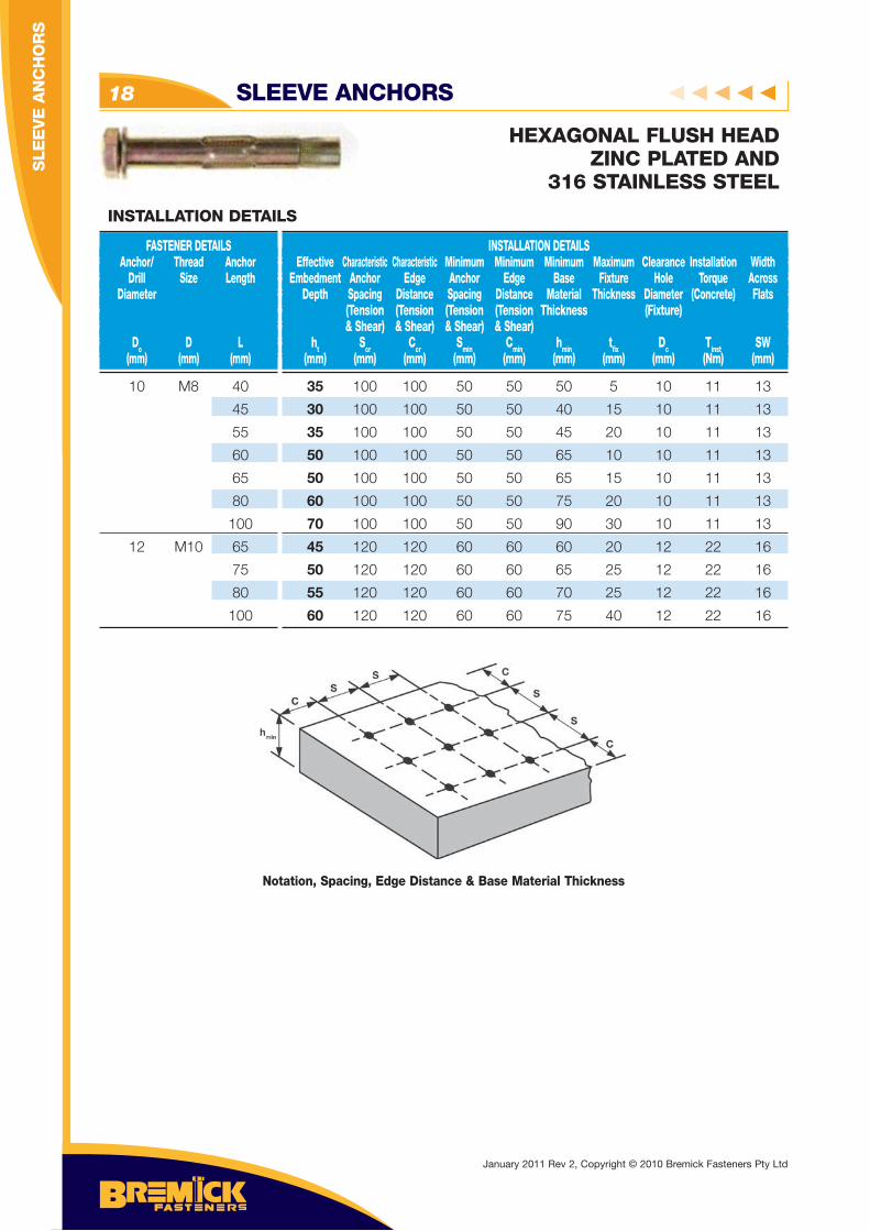
INSTALLATION DETAILS Effective Characteristic Characteristic Minimum Minimum Minimum Maximum Clearance Installation Width Embedment Anchor Edge Anchor Edge Base Fixture Hole Torque Across Depth Spacing Distance Spacing Distance Material Thickness Diameter (Concrete) Flats (Tension (Tension (Tension (Tension Thickness (Fixture) & Shear) & Shear) & Shear) & Shear) ht Scr Ccr Smin Cmin hmin tfi x Dc Tinst SW (mm) (mm) (mm) (mm) (mm) (mm) (mm) (mm) (Nm) (mm)
INSTALLATION DETAILS
35 100 100 50 50 50 5 10 11 13
30 100 100 50 50 40 15 10 11 13
35 100 100 50 50 45 20 10 11 13
50 100 100 50 50 65 10 10 11 13
50 100 100 50 50 65 15 10 11 13
60 100 100 50 50 75 20 10 11 13
70 100 100 50 50 90 30 10 11 13
45 120 120 60 60 60 20 12 22 16
50 120 120 60 60 65 25 12 22 16
55 120 120 60 60 70 25 12 22 16
60 120 120 60 60 75 40 12 22 16
Notation, Spacing, Edge Distance & Base Material Thickness
HEXAGONAL FLUSH HEADZINC PLATED AND
316 STAINLESS STEEL
January 2011 Rev 2, Copyright © 2010 Bremick Fasteners Pty Ltd
SLE
EV
E A
NC
HO
RS
SLEEVE ANCHORS 19
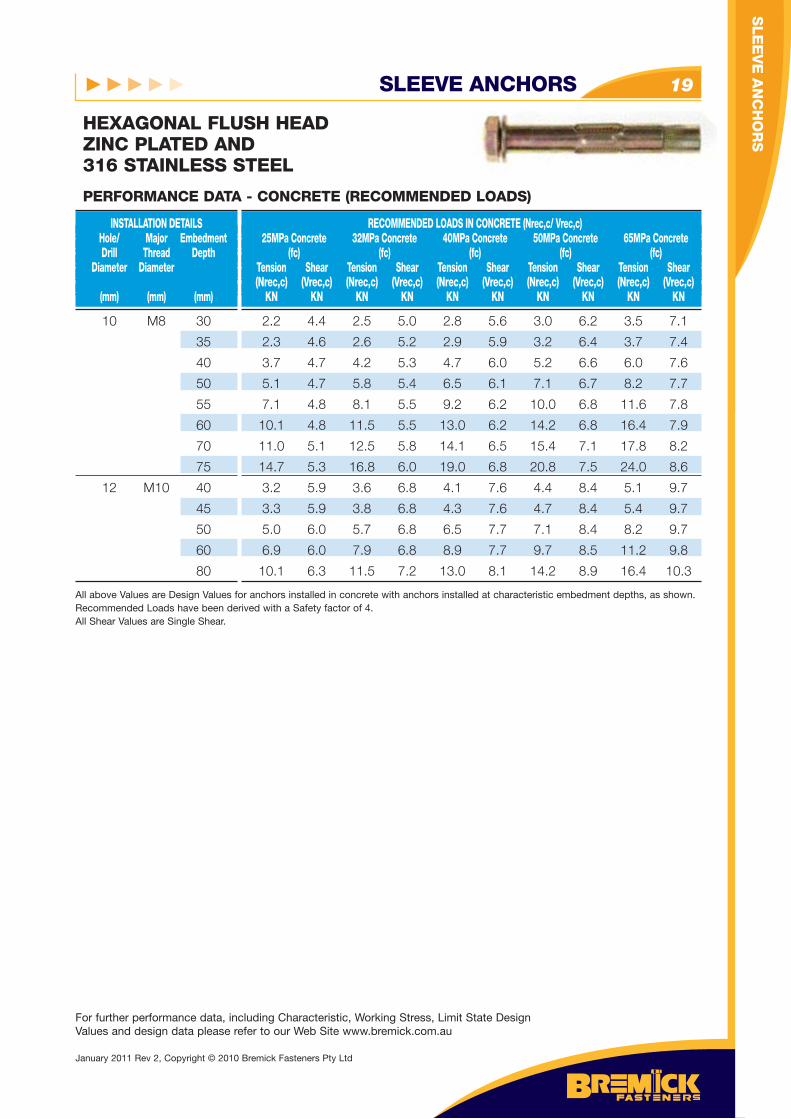
HEXAGONAL FLUSH HEADZINC PLATED AND 316 STAINLESS STEEL
10 M8 30
35
40
50
55
60
70
75
12 M10 40
45
50
60
80
INSTALLATION DETAILS Hole/ Major Embedment Drill Thread Depth Diameter Diameter (mm) (mm) (mm)
RECOMMENDED LOADS IN CONCRETE (Nrec,c/ Vrec,c) 25MPa Concrete 32MPa Concrete 40MPa Concrete 50MPa Concrete 65MPa Concrete (fc) (fc) (fc) (fc) (fc) Tension Shear Tension Shear Tension Shear Tension Shear Tension Shear (Nrec,c) (Vrec,c) (Nrec,c) (Vrec,c) (Nrec,c) (Vrec,c) (Nrec,c) (Vrec,c) (Nrec,c) (Vrec,c) KN KN KN KN KN KN KN KN KN KN
PERFORMANCE DATA - CONCRETE (RECOMMENDED LOADS)
2.2 4.4 2.5 5.0 2.8 5.6 3.0 6.2 3.5 7.1
2.3 4.6 2.6 5.2 2.9 5.9 3.2 6.4 3.7 7.4
3.7 4.7 4.2 5.3 4.7 6.0 5.2 6.6 6.0 7.6
5.1 4.7 5.8 5.4 6.5 6.1 7.1 6.7 8.2 7.7
7.1 4.8 8.1 5.5 9.2 6.2 10.0 6.8 11.6 7.8
10.1 4.8 11.5 5.5 13.0 6.2 14.2 6.8 16.4 7.9
11.0 5.1 12.5 5.8 14.1 6.5 15.4 7.1 17.8 8.2
14.7 5.3 16.8 6.0 19.0 6.8 20.8 7.5 24.0 8.6
3.2 5.9 3.6 6.8 4.1 7.6 4.4 8.4 5.1 9.7
3.3 5.9 3.8 6.8 4.3 7.6 4.7 8.4 5.4 9.7
5.0 6.0 5.7 6.8 6.5 7.7 7.1 8.4 8.2 9.7
6.9 6.0 7.9 6.8 8.9 7.7 9.7 8.5 11.2 9.8
10.1 6.3 11.5 7.2 13.0 8.1 14.2 8.9 16.4 10.3
All above Values are Design Values for anchors installed in concrete with anchors installed at characteristic embedment depths, as shown. Recommended Loads have been derived with a Safety factor of 4.All Shear Values are Single Shear.
For further performance data, including Characteristic, Working Stress, Limit State Design Values and design data please refer to our Web Site www.bremick.com.au
SLE
EV
E A
NC
HO
RS
January 2011 Rev 2, Copyright © 2010 Bremick Fasteners Pty Ltd
SLEEVE ANCHORS20
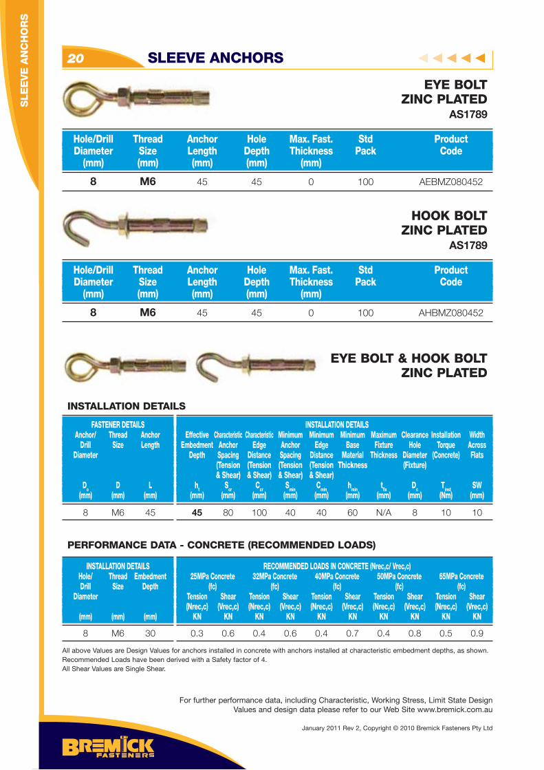
8 M6 45 45 0 100 AHBMZ080452
Hole/Drill Thread Anchor Hole Max. Fast. Std Product Diameter Size Length Depth Thickness Pack Code (mm) (mm) (mm) (mm) (mm)
HOOK BOLTZINC PLATED
AS1789
8 M6 45 45 0 100 AEBMZ080452
Hole/Drill Thread Anchor Hole Max. Fast. Std Product Diameter Size Length Depth Thickness Pack Code (mm) (mm) (mm) (mm) (mm)
EYE BOLTZINC PLATED
AS1789
For further performance data, including Characteristic, Working Stress, Limit State Design Values and design data please refer to our Web Site www.bremick.com.au
EYE BOLT & HOOK BOLTZINC PLATED
8 M6 45
FASTENER DETAILS Anchor/ Thread Anchor Drill Size Length Diameter
Do D L (mm) (mm) (mm)
INSTALLATION DETAILS Effective Characteristic Characteristic Minimum Minimum Minimum Maximum Clearance Installation Width Embedment Anchor Edge Anchor Edge Base Fixture Hole Torque Across Depth Spacing Distance Spacing Distance Material Thickness Diameter (Concrete) Flats (Tension (Tension (Tension (Tension Thickness (Fixture) & Shear) & Shear) & Shear) & Shear) ht Scr Ccr Smin Cmin hmin tfi x Dc Tinst SW (mm) (mm) (mm) (mm) (mm) (mm) (mm) (mm) (Nm) (mm)
INSTALLATION DETAILS
45 80 100 40 40 60 N/A 8 10 10
8 M6 30
INSTALLATION DETAILS Hole/ Thread Embedment Drill Size Depth Diameter (mm) (mm) (mm)
RECOMMENDED LOADS IN CONCRETE (Nrec,c/ Vrec,c) 25MPa Concrete 32MPa Concrete 40MPa Concrete 50MPa Concrete 65MPa Concrete (fc) (fc) (fc) (fc) (fc) Tension Shear Tension Shear Tension Shear Tension Shear Tension Shear (Nrec,c) (Vrec,c) (Nrec,c) (Vrec,c) (Nrec,c) (Vrec,c) (Nrec,c) (Vrec,c) (Nrec,c) (Vrec,c) KN KN KN KN KN KN KN KN KN KN
0.3 0.6 0.4 0.6 0.4 0.7 0.4 0.8 0.5 0.9
All above Values are Design Values for anchors installed in concrete with anchors installed at characteristic embedment depths, as shown. Recommended Loads have been derived with a Safety factor of 4.All Shear Values are Single Shear.
PERFORMANCE DATA - CONCRETE (RECOMMENDED LOADS)
SLE
EV
E A
NC
HO
RS
January 2011 Rev 2, Copyright © 2010 Bremick Fasteners Pty Ltd
SLEEVE ANCHOR - SUSPENSION 21
SLE
EV
E A
NC
HO
RS
- SU
SP
EN
SIO
N
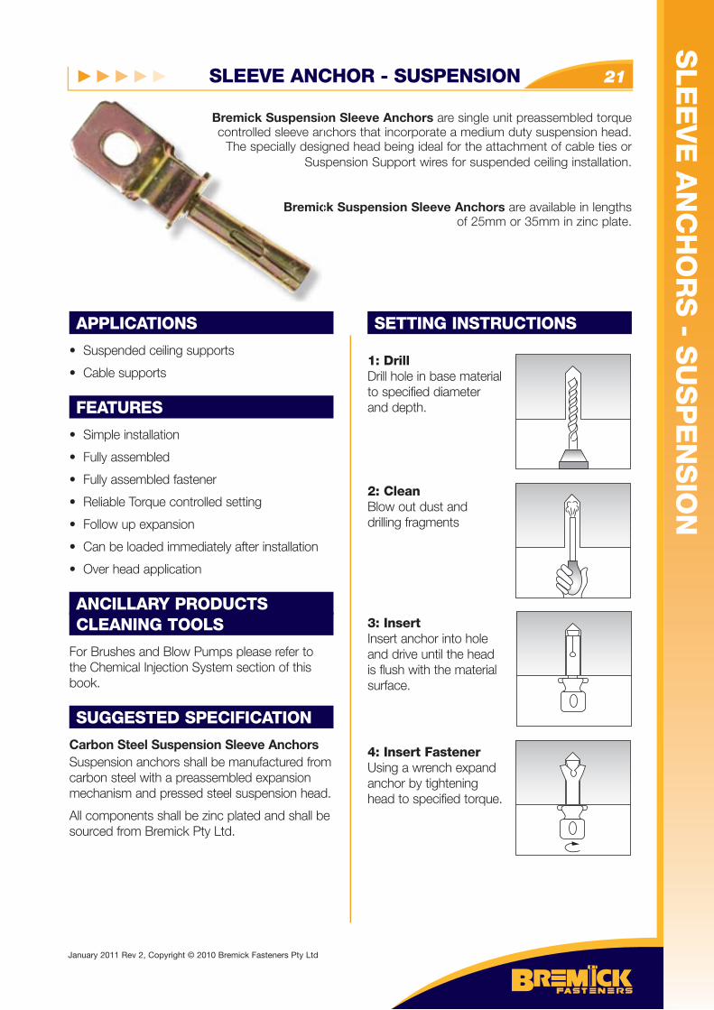
APPLICATIONS
• Suspended ceiling supports
• Cable supports
FEATURES
• Simple installation
• Fully assembled
• Fully assembled fastener
• Reliable Torque controlled setting
• Follow up expansion
• Can be loaded immediately after installation
• Over head application
ANCILLARY PRODUCTSCLEANING TOOLS
For Brushes and Blow Pumps please refer to the Chemical Injection System section of this book.
SUGGESTED SPECIFICATION
Carbon Steel Suspension Sleeve AnchorsSuspension anchors shall be manufactured from carbon steel with a preassembled expansion mechanism and pressed steel suspension head.
All components shall be zinc plated and shall be sourced from Bremick Pty Ltd.
SETTING INSTRUCTIONS
1: DrillDrill hole in base materialto specified diameter and depth.
2: CleanBlow out dust anddrilling fragments
3: InsertInsert anchor into hole and drive until the head is flush with the material surface.
4: Insert FastenerUsing a wrench expandanchor by tightening head to specified torque.
Bremick Suspension Sleeve Anchors are single unit preassembled torque controlled sleeve anchors that incorporate a medium duty suspension head.
The specially designed head being ideal for the attachment of cable ties or Suspension Support wires for suspended ceiling installation.
Bremick Suspension Sleeve Anchors are available in lengths of 25mm or 35mm in zinc plate.
Bremick Suspensiocontrolled sleeve an
The specially desigSus
Bremic
January 2011 Rev 2, Copyright © 2010 Bremick Fasteners Pty Ltd
SLEEVE ANCHOR - SUSPENSION22
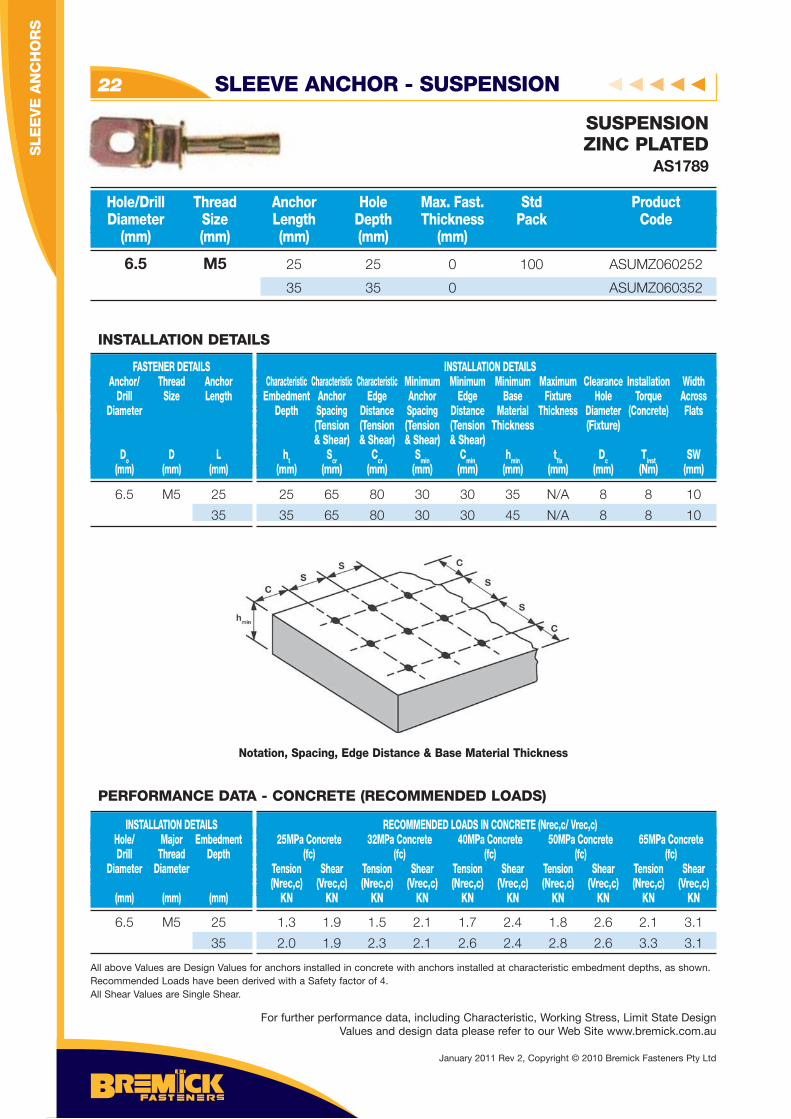
6.5 M5 25 25 0 100 ASUMZ060252
35 35 0 ASUMZ060352
Hole/Drill Thread Anchor Hole Max. Fast. Std Product Diameter Size Length Depth Thickness Pack Code (mm) (mm) (mm) (mm) (mm)
SUSPENSIONZINC PLATED
AS1789
6.5 M5 25
35
FASTENER DETAILS Anchor/ Thread Anchor Drill Size Length Diameter
Do D L (mm) (mm) (mm)
INSTALLATION DETAILS Characteristic Characteristic Characteristic Minimum Minimum Minimum Maximum Clearance Installation Width Embedment Anchor Edge Anchor Edge Base Fixture Hole Torque Across Depth Spacing Distance Spacing Distance Material Thickness Diameter (Concrete) Flats (Tension (Tension (Tension (Tension Thickness (Fixture) & Shear) & Shear) & Shear) & Shear) ht Scr Ccr Smin Cmin hmin tfi x Dc Tinst SW (mm) (mm) (mm) (mm) (mm) (mm) (mm) (mm) (Nm) (mm)
INSTALLATION DETAILS
25 65 80 30 30 35 N/A 8 8 10
35 65 80 30 30 45 N/A 8 8 10
Notation, Spacing, Edge Distance & Base Material Thickness
6.5 M5 25
35
INSTALLATION DETAILS Hole/ Major Embedment Drill Thread Depth Diameter Diameter (mm) (mm) (mm)
RECOMMENDED LOADS IN CONCRETE (Nrec,c/ Vrec,c) 25MPa Concrete 32MPa Concrete 40MPa Concrete 50MPa Concrete 65MPa Concrete (fc) (fc) (fc) (fc) (fc) Tension Shear Tension Shear Tension Shear Tension Shear Tension Shear (Nrec,c) (Vrec,c) (Nrec,c) (Vrec,c) (Nrec,c) (Vrec,c) (Nrec,c) (Vrec,c) (Nrec,c) (Vrec,c) KN KN KN KN KN KN KN KN KN KN
1.3 1.9 1.5 2.1 1.7 2.4 1.8 2.6 2.1 3.1
2.0 1.9 2.3 2.1 2.6 2.4 2.8 2.6 3.3 3.1
All above Values are Design Values for anchors installed in concrete with anchors installed at characteristic embedment depths, as shown. Recommended Loads have been derived with a Safety factor of 4.All Shear Values are Single Shear.
PERFORMANCE DATA - CONCRETE (RECOMMENDED LOADS)
For further performance data, including Characteristic, Working Stress, Limit State Design Values and design data please refer to our Web Site www.bremick.com.au
SLE
EV
E A
NC
HO
RS
January 2011 Rev 2, Copyright © 2010 Bremick Fasteners Pty Ltd
SLEEVE ANCHOR - SUSPENSION - TIE WIRE 23
SLE
EV
E A
NC
HO
RS
- SU
SP
EN
SIO
N
APPLICATIONS
• Suspended ceiling supports
• Cable tie supports
FEATURES
• High Load Capacity
• Fast and simple installation
• Fully assembled fastener
• Reliable force controlled setting
• Follow up expansion
• Can be loaded immediately after installation
• Over head application
ANCILLARY PRODUCTSCLEANING TOOLS
For Brushes and Blow Pumps please refer to the Chemical Injection System section of this book.
SUGGESTED SPECIFICATION
All cable/ceiling supports shall be one piece suspension tie wire anchors manufactured from carbon steel.
All components shall be zinc plated and shall be sourced from Bremick Pty Ltd.
SETTING INSTRUCTIONS
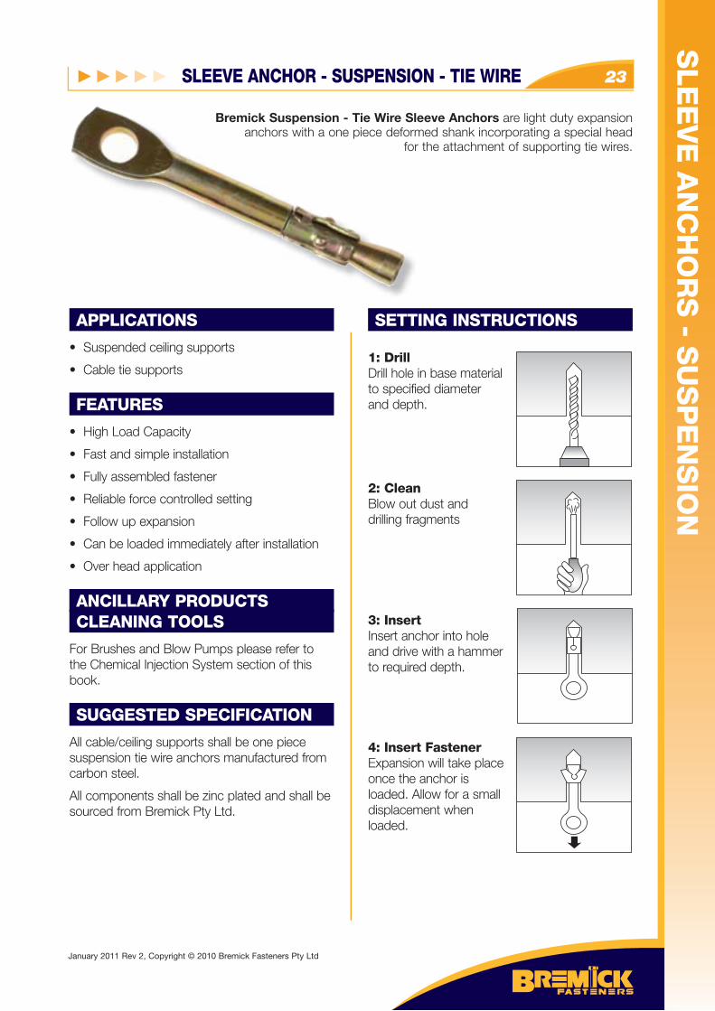
1: DrillDrill hole in base materialto specified diameter and depth.
2: CleanBlow out dust anddrilling fragments
3: InsertInsert anchor into hole and drive with a hammerto required depth.
4: Insert FastenerExpansion will take placeonce the anchor isloaded. Allow for a smalldisplacement whenloaded.
Bremick Suspension - Tie Wire Sleeve Anchors are light duty expansion anchors with a one piece deformed shank incorporating a special head
for the attachment of supporting tie wires.
Bremick Suspension - Tie Wire Slanchors with a one piece deform
for
January 2011 Rev 2, Copyright © 2010 Bremick Fasteners Pty Ltd
SLEEVE ANCHOR - SUSPENSION - TIE WIRE24
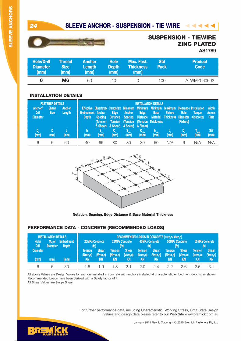
6 M6 60 40 0 100 ATWMZ060602
Hole/Drill Thread Anchor Hole Max. Fast. Std Product Diameter Size Length Depth Thickness Pack Code (mm) (mm) (mm) (mm) (mm)
SUSPENSION - TIEWIREZINC PLATED
AS1789
6 6 60
FASTENER DETAILS Anchor/ Shank Anchor Drill Size Length Diameter
Do D L (mm) (mm) (mm)
INSTALLATION DETAILS Effective Characteristic Characteristic Minimum Minimum Minimum Maximum Clearance Installation Width Embedment Anchor Edge Anchor Edge Base Fixture Hole Torque Across Depth Spacing Distance Spacing Distance Material Thickness Diameter (Concrete) Flats (Tension (Tension (Tension (Tension Thickness (Fixture) & Shear) & Shear) & Shear) & Shear) ht Scr Ccr Smin Cmin hmin tfi x Dc Tinst SW (mm) (mm) (mm) (mm) (mm) (mm) (mm) (mm) (Nm) (mm)
INSTALLATION DETAILS
40 65 80 30 30 50 N/A 6 N/A N/A
Notation, Spacing, Edge Distance & Base Material Thickness
6 6 30
INSTALLATION DETAILS Hole/ Major Embedment Drill Diameter Depth Diameter (mm) (mm) (mm)
RECOMMENDED LOADS IN CONCRETE (Nrec,c/ Vrec,c) 25MPa Concrete 32MPa Concrete 40MPa Concrete 50MPa Concrete 65MPa Concrete (fc) (fc) (fc) (fc) (fc) Tension Shear Tension Shear Tension Shear Tension Shear Tension Shear (Nrec,c) (Vrec,c) (Nrec,c) (Vrec,c) (Nrec,c) (Vrec,c) (Nrec,c) (Vrec,c) (Nrec,c) (Vrec,c) KN KN KN KN KN KN KN KN KN KN
1.6 1.9 1.8 2.1 2.0 2.4 2.2 2.6 2.6 3.1
All above Values are Design Values for anchors installed in concrete with anchors installed at characteristic embedment depths, as shown. Recommended Loads have been derived with a Safety factor of 4.All Shear Values are Single Shear.
PERFORMANCE DATA - CONCRETE (RECOMMENDED LOADS)
For further performance data, including Characteristic, Working Stress, Limit State Design Values and design data please refer to our Web Site www.bremick.com.au
SLE
EV
E A
NC
HO
RS
January 2011 Rev 2, Copyright © 2010 Bremick Fasteners Pty Ltd
THROUGH BOLTS 25
TH
RO
UG
H B
OLT
S
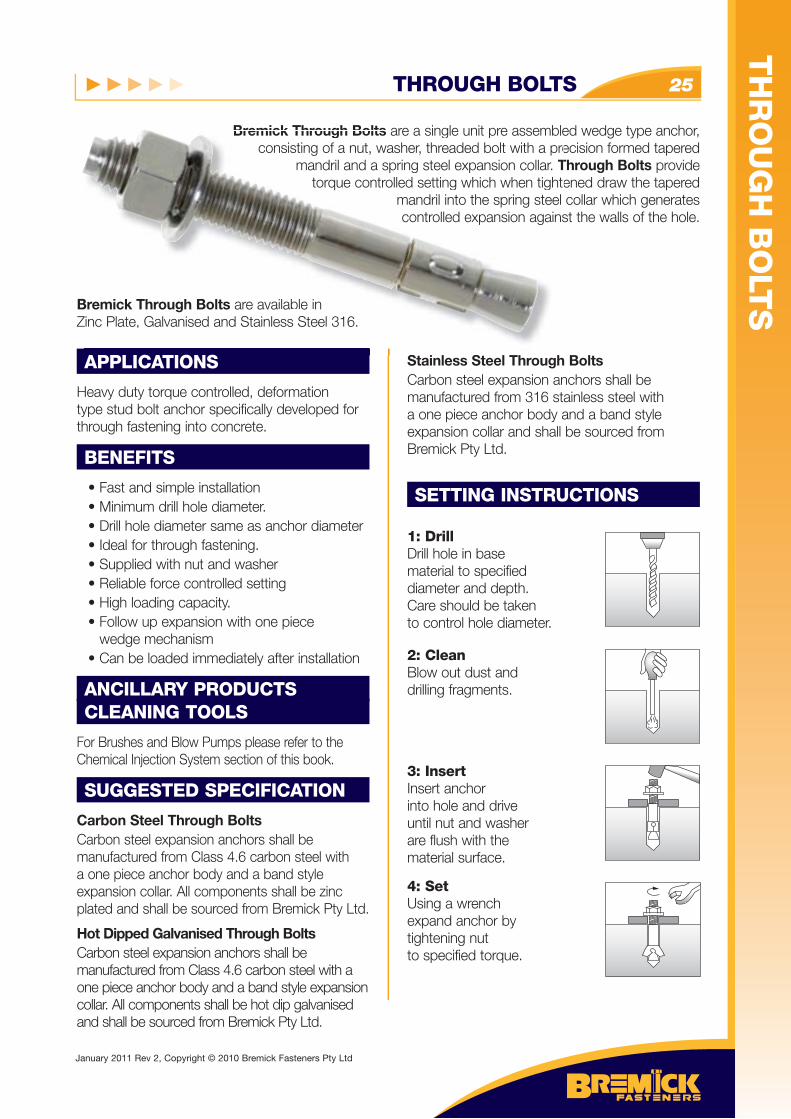
Bremick Through Bolts are a single unit pre assembled wedge type anchor, consisting of a nut, washer, threaded bolt with a precision formed tapered
mandril and a spring steel expansion collar. Through Bolts provide torque controlled setting which when tightened draw the tapered
mandril into the spring steel collar which generates controlled expansion against the walls of the hole.
Bremick Through Bolts are available in Zinc Plate, Galvanised and Stainless Steel 316.
APPLICATIONS
Heavy duty torque controlled, deformation type stud bolt anchor specifically developed for through fastening into concrete.
BENEFITS
• Fast and simple installation • Minimum drill hole diameter. • Drill hole diameter same as anchor diameter • Ideal for through fastening. • Supplied with nut and washer • Reliable force controlled setting • High loading capacity. • Follow up expansion with one piece wedge mechanism • Can be loaded immediately after installation
ANCILLARY PRODUCTSCLEANING TOOLS
For Brushes and Blow Pumps please refer to the Chemical Injection System section of this book.
SUGGESTED SPECIFICATION
Carbon Steel Through BoltsCarbon steel expansion anchors shall be manufactured from Class 4.6 carbon steel with a one piece anchor body and a band style expansion collar. All components shall be zinc plated and shall be sourced from Bremick Pty Ltd.
Hot Dipped Galvanised Through BoltsCarbon steel expansion anchors shall be manufactured from Class 4.6 carbon steel with a one piece anchor body and a band style expansion collar. All components shall be hot dip galvanised and shall be sourced from Bremick Pty Ltd.
Stainless Steel Through BoltsCarbon steel expansion anchors shall be manufactured from 316 stainless steel with a one piece anchor body and a band style expansion collar and shall be sourced from Bremick Pty Ltd.
SETTING INSTRUCTIONS
1: DrillDrill hole in base material to specifieddiameter and depth.Care should be takento control hole diameter.
2: CleanBlow out dust anddrilling fragments.
3: InsertInsert anchorinto hole and driveuntil nut and washerare flush with the material surface.
4: SetUsing a wrenchexpand anchor bytightening nutto specified torque.
Bremick Through Bolts are a single unit pre assembleconsisting of a nut, washer, threaded bolt with a pre
mandril and a spring steel expansion collar. Ttorque controlled setting which when tight
mandril into the spring steel controlled expansion agains
Bremick Through Bolts are available in Zinc Plate, Galvanised and Stainless Steel 316.
APPLICATIONS S i l S l Th h
January 2011 Rev 2, Copyright © 2010 Bremick Fasteners Pty Ltd
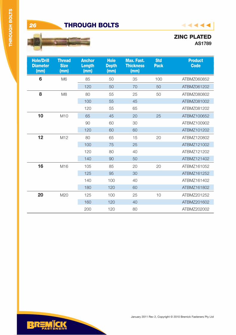
THROUGH BOLTS26
6 M6 85 50 35 100 ATBMZ060852
120 50 70 50 ATBMZ061202
8 M8 80 55 25 50 ATBMZ080802
100 55 45 ATBMZ081002
120 55 65 ATBMZ081202
10 M10 65 45 20 25 ATBMZ100652
90 60 30 ATBMZ100902
120 60 60 ATBMZ101202
12 M12 80 65 15 20 ATBMZ120802
100 75 25 ATBMZ121002
120 80 40 ATBMZ121202
140 90 50 ATBMZ121402
16 M16 105 85 20 20 ATBMZ161052
125 95 30 ATBMZ161252
140 100 40 ATBMZ161402
180 120 60 ATBMZ161802
20 M20 125 100 25 10 ATBMZ201252
160 120 40 ATBMZ201602
200 120 80 ATBMZ202002
Hole/Drill Thread Anchor Hole Max. Fast. Std Product Diameter Size Length Depth Thickness Pack Code (mm) (mm) (mm) (mm) (mm)
ZINC PLATEDAS1789
January 2011 Rev 2, Copyright © 2010 Bremick Fasteners Pty Ltd
TH
RO
UG
H B
OLT
S
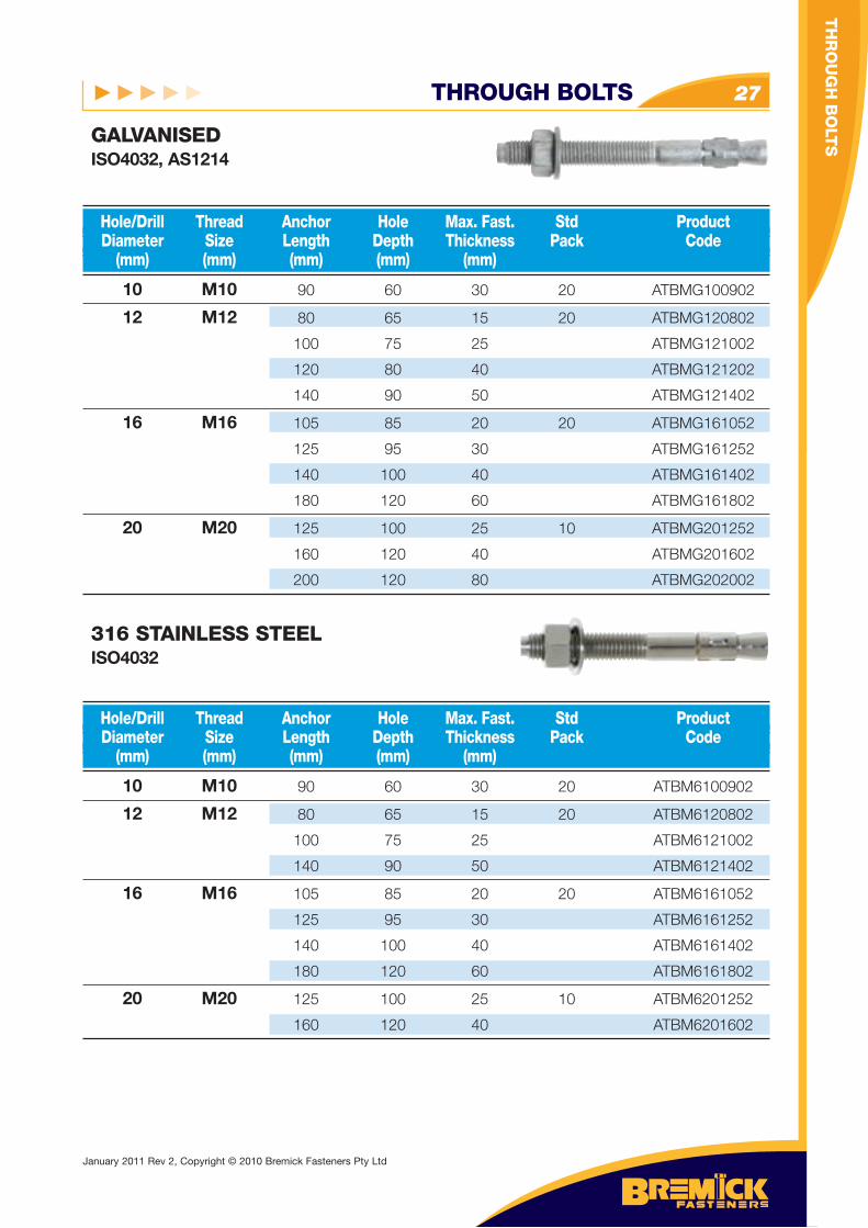
THROUGH BOLTS 27
10 M10 90 60 30 20 ATBMG100902
12 M12 80 65 15 20 ATBMG120802
100 75 25 ATBMG121002
120 80 40 ATBMG121202
140 90 50 ATBMG121402
16 M16 105 85 20 20 ATBMG161052
125 95 30 ATBMG161252
140 100 40 ATBMG161402
180 120 60 ATBMG161802
20 M20 125 100 25 10 ATBMG201252
160 120 40 ATBMG201602
200 120 80 ATBMG202002
Hole/Drill Thread Anchor Hole Max. Fast. Std Product Diameter Size Length Depth Thickness Pack Code (mm) (mm) (mm) (mm) (mm)
GALVANISEDISO4032, AS1214
10 M10 90 60 30 20 ATBM6100902
12 M12 80 65 15 20 ATBM6120802
100 75 25 ATBM6121002
140 90 50 ATBM6121402
16 M16 105 85 20 20 ATBM6161052
125 95 30 ATBM6161252
140 100 40 ATBM6161402
180 120 60 ATBM6161802
20 M20 125 100 25 10 ATBM6201252
160 120 40 ATBM6201602
Hole/Drill Thread Anchor Hole Max. Fast. Std Product Diameter Size Length Depth Thickness Pack Code (mm) (mm) (mm) (mm) (mm)
316 STAINLESS STEELISO4032
TH
RO
UG
H B
OLT
S
January 2011 Rev 2, Copyright © 2010 Bremick Fasteners Pty Ltd
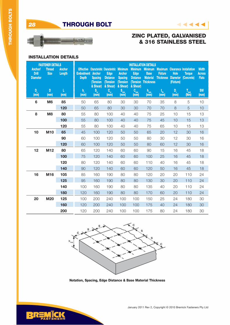
THROUGH BOLT28
ZINC PLATED, GALVANISED& 316 STAINLESS STEEL
Notation, Spacing, Edge Distance & Base Material Thickness
6 M6 85
120
8 M8 80
100
120
10 M10 65
90
120
12 M12 80
100
120
140
16 M16 105
125
140
180
20 M20 125
160
200
FASTENER DETAILS Anchor/ Thread Anchor Drill Size Length Diameter
Do D L (mm) (mm) (mm)
INSTALLATION DETAILS Effective Characteristic Characteristic Minimum Minimum Minimum Maximum Clearance Installation Width Embedment Anchor Edge Anchor Edge Base Fixture Hole Torque Across Depth Spacing Distance Spacing Distance Material Thickness Diameter (Concrete) Flats (Tension (Tension (Tension (Tension Thickness (Fixture) & Shear) & Shear) & Shear) & Shear) ht Scr Ccr Smin Cmin hmin tfi x Dc Tinst SW (mm) (mm) (mm) (mm) (mm) (mm) (mm) (mm) (Nm) (mm)
INSTALLATION DETAILS
50 65 80 30 30 70 35 8 5 10
50 65 80 30 30 70 70 8 5 10
55 80 100 40 40 75 25 10 15 13
55 80 100 40 40 75 45 10 15 13
55 80 100 40 40 75 65 10 15 13
45 100 120 50 50 65 20 12 30 16
60 100 120 50 50 80 30 12 30 16
60 100 120 50 50 80 60 12 30 16
65 120 140 60 60 90 15 16 45 18
75 120 140 60 60 100 25 16 45 18
80 120 140 60 60 110 40 16 45 18
90 120 140 60 60 120 50 16 45 18
85 160 190 80 80 120 20 20 110 24
95 160 190 80 80 130 30 20 110 24
100 160 190 80 80 135 40 20 110 24
120 160 190 80 80 170 60 20 110 24
100 200 240 100 100 150 25 24 180 30
120 200 240 100 100 175 40 24 180 30
120 200 240 100 100 175 80 24 180 30
January 2011 Rev 2, Copyright © 2010 Bremick Fasteners Pty Ltd
TH
RO
UG
H B
OLT
S
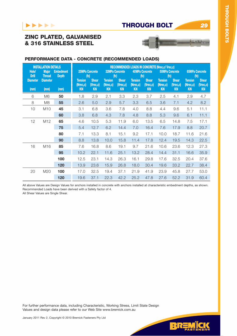
THROUGH BOLT 29
ZINC PLATED, GALVANISED& 316 STAINLESS STEEL
For further performance data, including Characteristic, Working Stress, Limit State Design Values and design data please refer to our Web Site www.bremick.com.au
6 M6 50
8 M8 55
10 M10 45
60
12 M12 65
75
80
90
16 M16 85
95
100
120
20 M20 100
120
INSTALLATION DETAILS Hole/ Major Embedment Drill Thread Depth Diameter Diameter (mm) (mm) (mm)
RECOMMENDED LOADS IN CONCRETE (Nrec,c/ Vrec,c) 25MPa Concrete 32MPa Concrete 40MPa Concrete 50MPa Concrete 65MPa Concrete (fc) (fc) (fc) (fc) (fc) Tension Shear Tension Shear Tension Shear Tension Shear Tension Shear (Nrec,c) (Vrec,c) (Nrec,c) (Vrec,c) (Nrec,c) (Vrec,c) (Nrec,c) (Vrec,c) (Nrec,c) (Vrec,c) KN KN KN KN KN KN KN KN KN KN
PERFORMANCE DATA - CONCRETE (RECOMMENDED LOADS)
1.8 2.9 2.1 3.3 2.3 3.7 2.5 4.1 2.9 4.7
2.6 5.0 2.9 5.7 3.3 6.5 3.6 7.1 4.2 8.2
3.1 6.8 3.6 7.8 4.0 8.8 4.4 9.6 5.1 11.1
3.8 6.8 4.3 7.8 4.8 8.8 5.3 9.6 6.1 11.1
4.6 10.5 5.3 11.9 6.0 13.5 6.5 14.8 7.5 17.1
5.4 12.7 6.2 14.4 7.0 16.4 7.6 17.9 8.8 20.7
7.1 13.3 8.1 15.1 9.2 17.1 10.0 18.7 11.6 21.6
8.8 13.8 10.0 15.8 11.4 17.8 12.4 19.5 14.3 22.5
7.6 16.8 8.6 19.1 9.7 21.6 10.6 23.6 12.3 27.3
10.2 22.1 11.6 25.1 13.2 28.4 14.4 31.1 16.6 35.9
12.5 23.1 14.3 26.3 16.1 29.8 17.6 32.5 20.4 37.6
13.9 23.6 15.9 26.8 18.0 30.4 19.6 33.2 22.7 38.4
17.0 32.5 19.4 37.1 21.9 41.9 23.9 45.8 27.7 53.0
19.6 37.1 22.3 42.2 25.2 47.8 27.6 52.2 31.9 60.4
All above Values are Design Values for anchors installed in concrete with anchors installed at characteristic embedment depths, as shown. Recommended Loads have been derived with a Safety factor of 4.All Shear Values are Single Shear.
TH
RO
UG
H B
OLT
S
January 2011 Rev 2, Copyright © 2010 Bremick Fasteners Pty Ltd
DROP-IN ANCHORS30
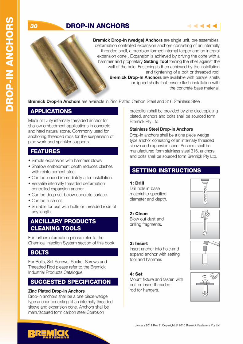
Bremick Drop-In (wedge) Anchors are single unit, pre assembles, deformation controlled expansion anchors consisting of an internally
threaded shell, a precision formed internal tapper and an integral expansion cone . Expansion is achieved by driving the cone with a hammer and proprietary Setting Tool forcing the shell against the
wall of the hole. Fastening is then achieved by the installation and tightening of a bolt or threaded rod.
Bremick Drop-In Anchors are available with parallel shells or lipped shells that ensure flush installation with
the concrete base material.
Bremick Drop-In Anchors are available in Zinc Plated Carbon Steel and 316 Stainless Steel.
APPLICATIONS
Medium Duty internally threaded anchor for shallow embedment applications in concrete and hard natural stone. Commonly used for anchoring threaded rods for the suspension of pipe work and sprinkler supports.
FEATURES
• Simple expansion with hammer blows • Shallow embedment depth reduces clashes with reinforcement steel.• Can be loaded immediately after installation.• Versatile internally threaded deformation controlled expansion anchor.• Can be deep set below concrete surface.• Can be flush set • Suitable for use with bolts or threaded rods of any length
ANCILLARY PRODUCTSCLEANING TOOLS
For further information please refer to the Chemical Injection System section of this book.
BOLTS
For Bolts, Set Screws, Socket Screws and Threaded Rod please refer to the Bremick Industrial Products Catalogue.
SUGGESTED SPECIFICATION
Zinc Plated Drop-In AnchorsDrop-In anchors shall be a one piece wedge type anchor consisting of an internally threaded sleeve and expansion cone. Anchors shall be manufactured form carbon steel Corrosion
protection shall be provided by zinc electroplating plated, anchors and bolts shall be sourced form Bremick Pty Ltd.
Stainless Steel Drop-In AnchorsDrop-In anchors shall be a one piece wedge type anchor consisting of an internally threaded sleeve and expansion cone. Anchors shall be manufactured form stainless steel 316, anchors and bolts shall be sourced form Bremick Pty Ltd.
SETTING INSTRUCTIONS
1: DrillDrill hole in base material to specifieddiameter and depth.
2: CleanBlow out dust anddrilling fragments.
3: InsertInsert anchor into hole and expand anchor with setting tool and hammer.
4: SetMount fixture and fasten withbolt or insert threadedrod for hangers.
Bremick deformat
threadexpansihamme
wa
B
DR
OP
-IN
AN
CH
OR
S
January 2011 Rev 2, Copyright © 2010 Bremick Fasteners Pty Ltd
DROP-IN ANCHORS 31
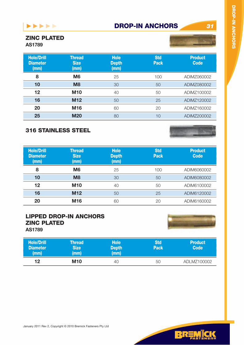
8 M6 25 100 ADIMZ060002
10 M8 30 50 ADIMZ080002
12 M10 40 50 ADIMZ100002
16 M12 50 25 ADIMZ120002
20 M16 60 20 ADIMZ160002
25 M20 80 10 ADIMZ200002
Hole/Drill Thread Hole Std Product Diameter Size Depth Pack Code (mm) (mm) (mm)
ZINC PLATEDAS1789
8 M6 25 100 ADIM6060002
10 M8 30 50 ADIM6080002
12 M10 40 50 ADIM6100002
16 M12 50 25 ADIM6120002
20 M16 60 20 ADIM6160002
Hole/Drill Thread Hole Std Product Diameter Size Depth Pack Code (mm) (mm) (mm)
316 STAINLESS STEEL
12 M10 40 50 ADLMZ100002
Hole/Drill Thread Hole Std Product Diameter Size Depth Pack Code (mm) (mm) (mm)
LIPPED DROP-IN ANCHORSZINC PLATEDAS1789
DR
OP
-IN A
NC
HO
RS
January 2011 Rev 2, Copyright © 2010 Bremick Fasteners Pty Ltd
DROP-IN ANCHORS32
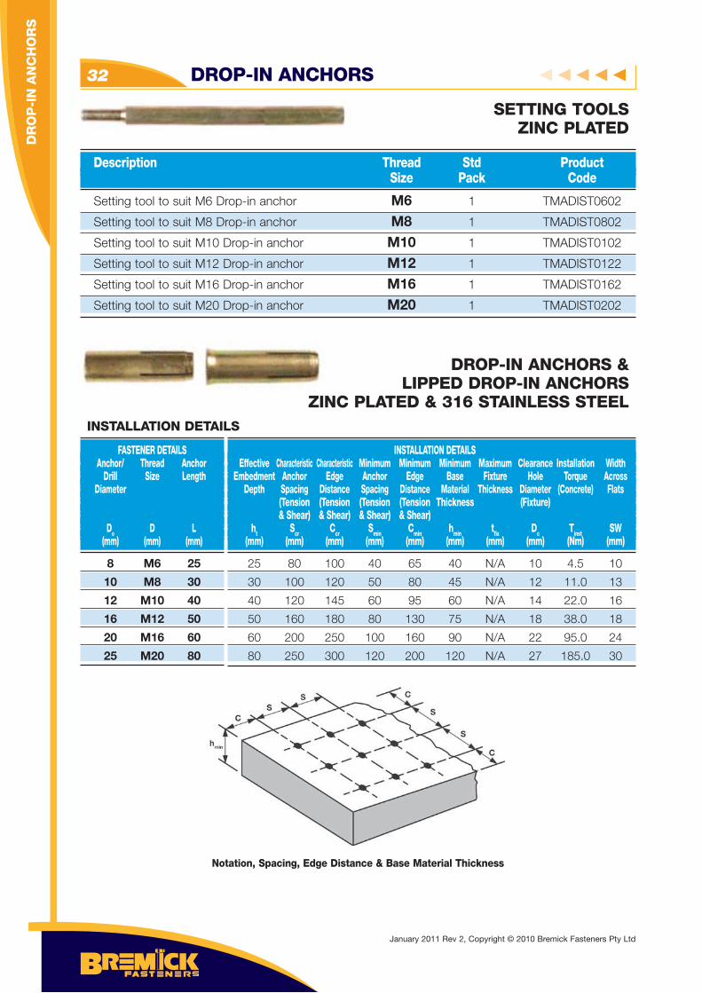
Setting tool to suit M6 Drop-in anchor M6 1 TMADIST0602
Setting tool to suit M8 Drop-in anchor M8 1 TMADIST0802
Setting tool to suit M10 Drop-in anchor M10 1 TMADIST0102
Setting tool to suit M12 Drop-in anchor M12 1 TMADIST0122
Setting tool to suit M16 Drop-in anchor M16 1 TMADIST0162
Setting tool to suit M20 Drop-in anchor M20 1 TMADIST0202
Description Thread Std Product Size Pack Code
SETTING TOOLSZINC PLATED
DROP-IN ANCHORS & LIPPED DROP-IN ANCHORS
ZINC PLATED & 316 STAINLESS STEEL
Notation, Spacing, Edge Distance & Base Material Thickness
8 M6 25
10 M8 30
12 M10 40
16 M12 50
20 M16 60
25 M20 80
FASTENER DETAILS Anchor/ Thread Anchor Drill Size Length Diameter
Do D L (mm) (mm) (mm)
INSTALLATION DETAILS Effective Characteristic Characteristic Minimum Minimum Minimum Maximum Clearance Installation Width Embedment Anchor Edge Anchor Edge Base Fixture Hole Torque Across Depth Spacing Distance Spacing Distance Material Thickness Diameter (Concrete) Flats (Tension (Tension (Tension (Tension Thickness (Fixture) & Shear) & Shear) & Shear) & Shear) ht Scr Ccr Smin Cmin hmin tfi x Dc Tinst SW (mm) (mm) (mm) (mm) (mm) (mm) (mm) (mm) (Nm) (mm)
INSTALLATION DETAILS
25 80 100 40 65 40 N/A 10 4.5 10
30 100 120 50 80 45 N/A 12 11.0 13
40 120 145 60 95 60 N/A 14 22.0 16
50 160 180 80 130 75 N/A 18 38.0 18
60 200 250 100 160 90 N/A 22 95.0 24
80 250 300 120 200 120 N/A 27 185.0 30
DR
OP
-IN
AN
CH
OR
S
January 2011 Rev 2, Copyright © 2010 Bremick Fasteners Pty Ltd
DROP-IN ANCHORS 33
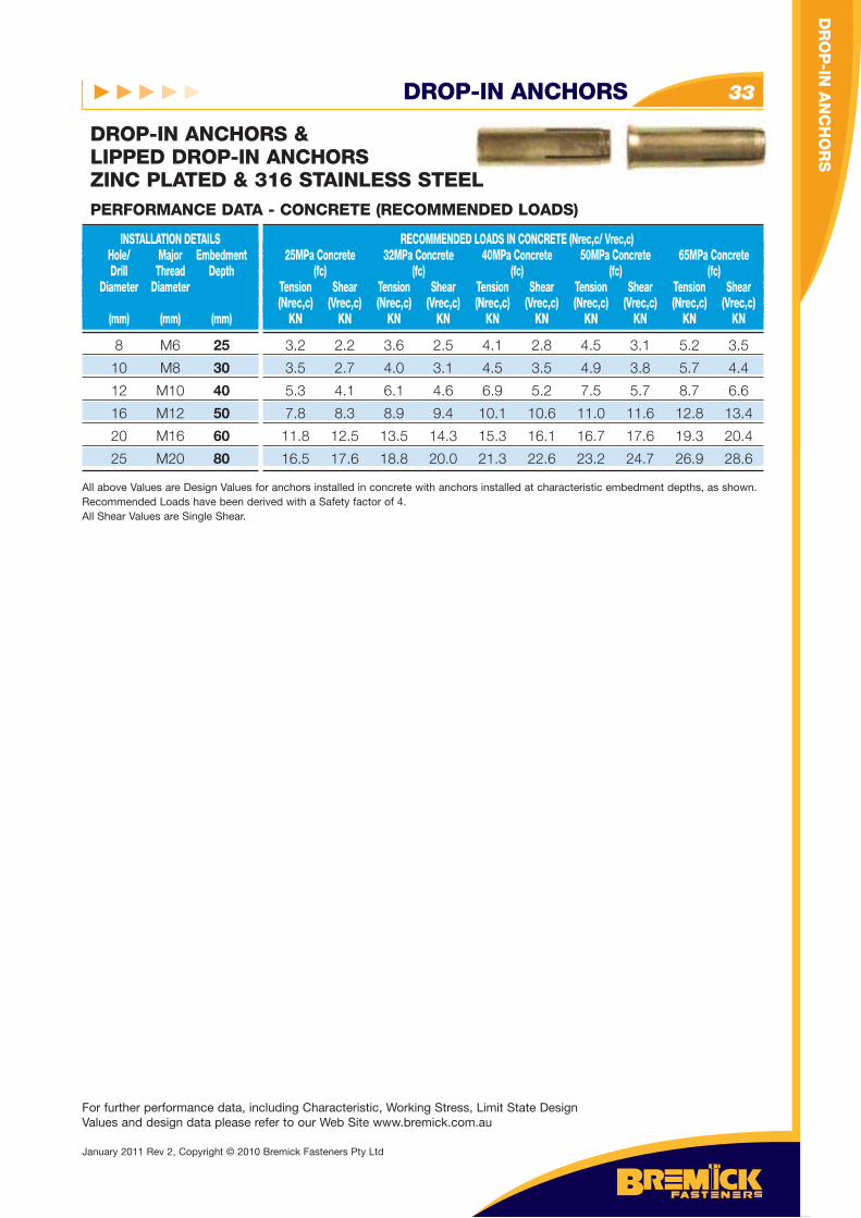
8 M6 25
10 M8 30
12 M10 40
16 M12 50
20 M16 60
25 M20 80
INSTALLATION DETAILS Hole/ Major Embedment Drill Thread Depth Diameter Diameter (mm) (mm) (mm)
RECOMMENDED LOADS IN CONCRETE (Nrec,c/ Vrec,c) 25MPa Concrete 32MPa Concrete 40MPa Concrete 50MPa Concrete 65MPa Concrete (fc) (fc) (fc) (fc) (fc) Tension Shear Tension Shear Tension Shear Tension Shear Tension Shear (Nrec,c) (Vrec,c) (Nrec,c) (Vrec,c) (Nrec,c) (Vrec,c) (Nrec,c) (Vrec,c) (Nrec,c) (Vrec,c) KN KN KN KN KN KN KN KN KN KN
PERFORMANCE DATA - CONCRETE (RECOMMENDED LOADS)
3.2 2.2 3.6 2.5 4.1 2.8 4.5 3.1 5.2 3.5
3.5 2.7 4.0 3.1 4.5 3.5 4.9 3.8 5.7 4.4
5.3 4.1 6.1 4.6 6.9 5.2 7.5 5.7 8.7 6.6
7.8 8.3 8.9 9.4 10.1 10.6 11.0 11.6 12.8 13.4
11.8 12.5 13.5 14.3 15.3 16.1 16.7 17.6 19.3 20.4
16.5 17.6 18.8 20.0 21.3 22.6 23.2 24.7 26.9 28.6
All above Values are Design Values for anchors installed in concrete with anchors installed at characteristic embedment depths, as shown. Recommended Loads have been derived with a Safety factor of 4.All Shear Values are Single Shear.
DROP-IN ANCHORS & LIPPED DROP-IN ANCHORSZINC PLATED & 316 STAINLESS STEEL
For further performance data, including Characteristic, Working Stress, Limit State Design Values and design data please refer to our Web Site www.bremick.com.au
DR
OP
-IN A
NC
HO
RS
January 2011 Rev 2, Copyright © 2010 Bremick Fasteners Pty Ltd
SHIELD ANCHORS34
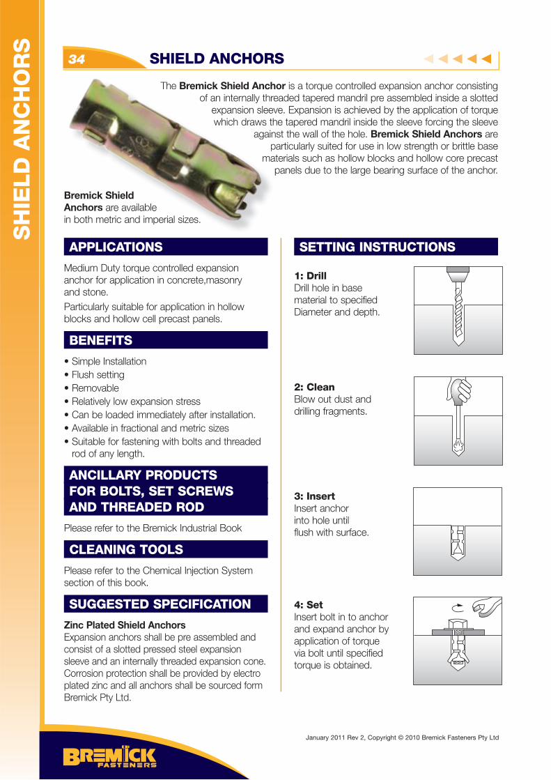
The Bremick Shield Anchor is a torque controlled expansion anchor consisting of an internally threaded tapered mandril pre assembled inside a slotted
expansion sleeve. Expansion is achieved by the application of torque which draws the tapered mandril inside the sleeve forcing the sleeve
against the wall of the hole. Bremick Shield Anchors are particularly suited for use in low strength or brittle base
materials such as hollow blocks and hollow core precast panels due to the large bearing surface of the anchor.
Bremick Shield Anchors are available in both metric and imperial sizes.
APPLICATIONS
Medium Duty torque controlled expansion anchor for application in concrete,masonry and stone.Particularly suitable for application in hollow blocks and hollow cell precast panels.
BENEFITS
• Simple Installation • Flush setting• Removable • Relatively low expansion stress• Can be loaded immediately after installation.• Available in fractional and metric sizes• Suitable for fastening with bolts and threaded rod of any length.
ANCILLARY PRODUCTSFOR BOLTS, SET SCREWS AND THREADED ROD
Please refer to the Bremick Industrial Book
CLEANING TOOLS
Please refer to the Chemical Injection System section of this book.
SUGGESTED SPECIFICATION
Zinc Plated Shield AnchorsExpansion anchors shall be pre assembled and consist of a slotted pressed steel expansion sleeve and an internally threaded expansion cone. Corrosion protection shall be provided by electro plated zinc and all anchors shall be sourced form Bremick Pty Ltd.
SETTING INSTRUCTIONS
1: DrillDrill hole in base material to specifiedDiameter and depth.
2: CleanBlow out dust anddrilling fragments.
3: InsertInsert anchorinto hole untilflush with surface.
4: SetInsert bolt in to anchor and expand anchor byapplication of torquevia bolt until specifiedtorque is obtained.
The Bremick Shield Anchof an internally thr
expansion sleevwhich draws th
againp
ma
remick Shield Anchors are available
both metric and imperial sizes.
SH
IELD
AN
CH
OR
S
January 2011 Rev 2, Copyright © 2010 Bremick Fasteners Pty Ltd
SHIELD ANCHORS 35
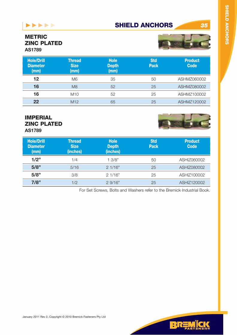
12 M6 35 50 ASHMZ060002
16 M8 52 25 ASHMZ080002
16 M10 52 25 ASHMZ100002
22 M12 65 25 ASHMZ120002
Hole/Drill Thread Hole Std Product Diameter Size Depth Pack Code (mm) (mm) (mm)
METRICZINC PLATEDAS1789
1/2” 1/4 1 3/8” 50 ASHIZ060002
5/8” 5/16 2 1/16” 25 ASHIZ080002
5/8” 3/8 2 1/16” 25 ASHIZ100002
7/8” 1/2 2 9/16” 25 ASHIZ120002
For Set Screws, Bolts and Washers refer to the Bremick Industrial Book.
Hole/Drill Thread Hole Std Product Diameter Size Depth Pack Code (mm) (inches) (inches)
IMPERIALZINC PLATEDAS1789
SH
IELD
AN
CH
OR
S
January 2011 Rev 2, Copyright © 2010 Bremick Fasteners Pty Ltd
SHIELD ANCHORS36
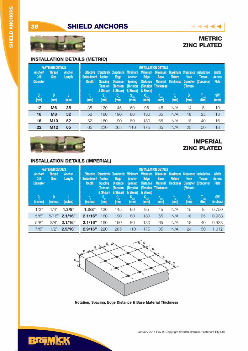
METRICZINC PLATED
12 M6 35
16 M8 52
16 M10 52
22 M12 65
FASTENER DETAILS Anchor/ Thread Anchor Drill Size Length Diameter
Do D L (mm) (mm) (mm)
INSTALLATION DETAILS Effective Characteristic Characteristic Minimum Minimum Minimum Maximum Clearance Installation Width Embedment Anchor Edge Anchor Edge Base Fixture Hole Torque Across Depth Spacing Distance Spacing Distance Material Thickness Diameter (Concrete) Flats (Tension (Tension (Tension (Tension Thickness (Fixture) & Shear) & Shear) & Shear) & Shear) ht Scr Ccr Smin Cmin hmin tfi x Dc Tinst SW (mm) (mm) (mm) (mm) (mm) (mm) (mm) (mm) (Nm) (mm)
INSTALLATION DETAILS (METRIC)
35 120 145 60 95 45 N/A 14 8 10
52 160 190 80 130 65 N/A 18 25 13
52 160 190 80 130 65 N/A 18 40 16
65 220 265 110 175 85 N/A 25 50 18
IMPERIALZINC PLATED
1/2” 1/4” 1.3/8”
5/8” 5/16” 2.1/16”
5/8” 3/8” 2.1/16”
7/8” 1/2” 2.9/16”
FASTENER DETAILS Anchor/ Thread Anchor Drill Size Length Diameter
Do D L (inches) (inches) (inches)
INSTALLATION DETAILS Effective Characteristic Characteristic Minimum Minimum Minimum Maximum Clearance Installation Width Embedment Anchor Edge Anchor Edge Base Fixture Hole Torque Across Depth Spacing Distance Spacing Distance Material Thickness Diameter (Concrete) Flats (Tension (Tension (Tension (Tension Thickness (Fixture) & Shear) & Shear) & Shear) & Shear) ht Scr Ccr Smin Cmin hmin tfi x Dc Tinst SW (inches) (mm) (mm) (mm) (mm) (mm) (mm) (mm) (Nm) (inches)
INSTALLATION DETAILS (IMPERIAL)
1.3/8” 120 145 60 95 45 N/A 15 8 0.750
2.1/16” 160 190 80 130 65 N/A 18 25 0.938
2.1/16” 160 190 80 130 65 N/A 18 40 0.938
2.9/16” 220 265 110 175 85 N/A 24 50 1.312
Notation, Spacing, Edge Distance & Base Material Thickness
January 2011 Rev 2, Copyright © 2010 Bremick Fasteners Pty Ltd
SH
IELD
AN
CH
OR
S
SHIELD ANCHORS 37
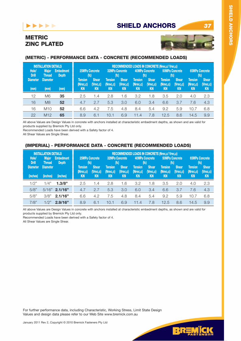
METRICZINC PLATED
12 M6 35
16 M8 52
16 M10 52
22 M12 65
INSTALLATION DETAILS Hole/ Major Embedment Drill Thread Depth Diameter Diameter (mm) (mm) (mm)
RECOMMENDED LOADS IN CONCRETE (Nrec,c/ Vrec,c) 25MPa Concrete 32MPa Concrete 40MPa Concrete 50MPa Concrete 65MPa Concrete (fc) (fc) (fc) (fc) (fc) Tension Shear Tension Shear Tension Shear Tension Shear Tension Shear (Nrec,c) (Vrec,c) (Nrec,c) (Vrec,c) (Nrec,c) (Vrec,c) (Nrec,c) (Vrec,c) (Nrec,c) (Vrec,c) KN KN KN KN KN KN KN KN KN KN
2.5 1.4 2.8 1.6 3.2 1.8 3.5 2.0 4.0 2.3
4.7 2.7 5.3 3.0 6.0 3.4 6.6 3.7 7.6 4.3
6.6 4.2 7.5 4.8 8.4 5.4 9.2 5.9 10.7 6.8
8.9 6.1 10.1 6.9 11.4 7.8 12.5 8.6 14.5 9.9
All above Values are Design Values in concrete with anchors installed at characteristic embedment depths, as shown and are valid for products supplied by Bremick Pty Ltd only. Recommended Loads have been derived with a Safety factor of 4.All Shear Values are Single Shear.
(METRIC) - PERFORMANCE DATA - CONCRETE (RECOMMENDED LOADS)
(IMPERIAL) - PERFORMANCE DATA - CONCRETE (RECOMMENDED LOADS)
1/2” 1/4” 1.3/8”
5/8” 5/16” 2.1/16”
5/8” 3/8” 2.1/16”
7/8” 1/2” 2.9/16”
INSTALLATION DETAILS Hole/ Major Embedment Drill Thread Depth Diameter Diameter (inches) (inches) (inches)
RECOMMENDED LOADS IN CONCRETE (Nrec,c/ Vrec,c) 25MPa Concrete 32MPa Concrete 40MPa Concrete 50MPa Concrete 65MPa Concrete (fc) (fc) (fc) (fc) (fc) Tension Shear Tension Shear Tension Shear Tension Shear Tension Shear (Nrec,c) (Vrec,c) (Nrec,c) (Vrec,c) (Nrec,c) (Vrec,c) (Nrec,c) (Vrec,c) (Nrec,c) (Vrec,c) KN KN KN KN KN KN KN KN KN KN
2.5 1.4 2.8 1.6 3.2 1.8 3.5 2.0 4.0 2.3
4.7 2.7 5.3 3.0 6.0 3.4 6.6 3.7 7.6 4.3
6.6 4.2 7.5 4.8 8.4 5.4 9.2 5.9 10.7 6.8
8.9 6.1 10.1 6.9 11.4 7.8 12.5 8.6 14.5 9.9
All above Values are Design Values in concrete with anchors installed at characteristic embedment depths, as shown and are valid for products supplied by Bremick Pty Ltd only. Recommended Loads have been derived with a Safety factor of 4.All Shear Values are Single Shear.
For further performance data, including Characteristic, Working Stress, Limit State Design Values and design data please refer to our Web Site www.bremick.com.au
SH
IELD
AN
CH
OR
S
January 2011 Rev 2, Copyright © 2010 Bremick Fasteners Pty Ltd
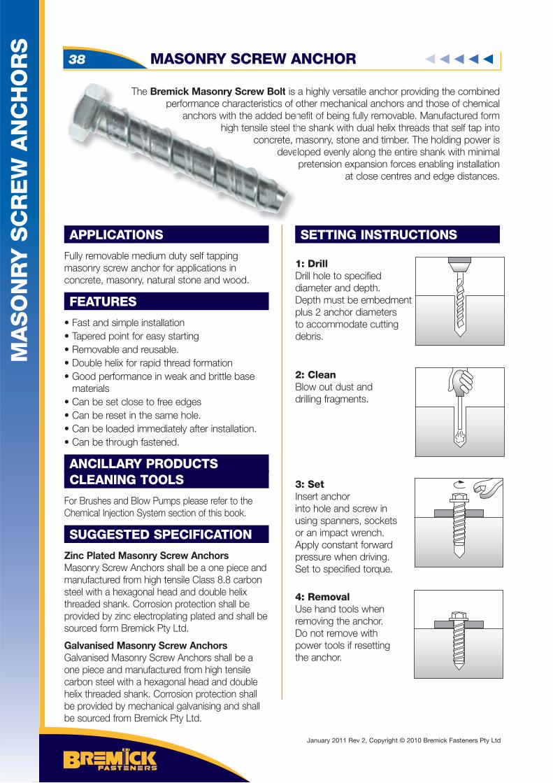
The Bremick Masonry Screw Bolt is a highly versatile anchor providing the combined performance characteristics of other mechanical anchors and those of chemical
anchors with the added benefit of being fully removable. Manufactured form high tensile steel the shank with dual helix threads that self tap into
concrete, masonry, stone and timber. The holding power is developed evenly along the entire shank with minimal
pretension expansion forces enabling installation at close centres and edge distances.
APPLICATIONS
Fully removable medium duty self tapping masonry screw anchor for applications in concrete, masonry, natural stone and wood.
FEATURES
• Fast and simple installation• Tapered point for easy starting • Removable and reusable.• Double helix for rapid thread formation• Good performance in weak and brittle base materials• Can be set close to free edges• Can be reset in the same hole.• Can be loaded immediately after installation.• Can be through fastened.
ANCILLARY PRODUCTSCLEANING TOOLS
For Brushes and Blow Pumps please refer to the Chemical Injection System section of this book.
SUGGESTED SPECIFICATION
Zinc Plated Masonry Screw AnchorsMasonry Screw Anchors shall be a one piece and manufactured from high tensile Class 8.8 carbon steel with a hexagonal head and double helix threaded shank. Corrosion protection shall be provided by zinc electroplating plated and shall be sourced form Bremick Pty Ltd.
Galvanised Masonry Screw AnchorsGalvanised Masonry Screw Anchors shall be a one piece and manufactured from high tensile carbon steel with a hexagonal head and double helix threaded shank. Corrosion protection shall be provided by mechanical galvanising and shall be sourced from Bremick Pty Ltd.
SETTING INSTRUCTIONS
1: DrillDrill hole to specifieddiameter and depth.Depth must be embedmentplus 2 anchor diametersto accommodate cuttingdebris.
2: CleanBlow out dust anddrilling fragments.
3: SetInsert anchorinto hole and screw inusing spanners, socketsor an impact wrench.Apply constant forward pressure when driving.Set to specified torque.
4: RemovalUse hand tools whenremoving the anchor. Do not remove withpower tools if resettingthe anchor.
The Bremick Masonry Screw Bolt is tperformance characteristics of o
anchors with the added ben high tensile steel th
concrete, mdeve
MA
SO
NR
Y S
CR
EW
AN
CH
OR
S
MASONRY SCREW ANCHOR38
January 2011 Rev 2, Copyright © 2010 Bremick Fasteners Pty Ltd
MASONRY SCREW ANCHORS 39
MA
SO
NR
Y
SC
RE
W A
NC
HO
RS
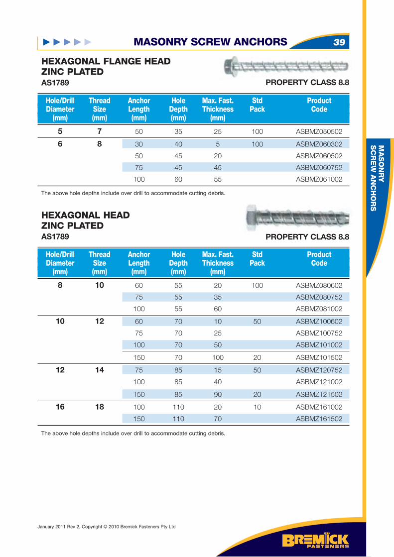
5 7 50 35 25 100 ASBMZ050502
6 8 30 40 5 100 ASBMZ060302
50 45 20 ASBMZ060502
75 45 45 ASBMZ060752
100 60 55 ASBMZ061002
Hole/Drill Thread Anchor Hole Max. Fast. Std Product Diameter Size Length Depth Thickness Pack Code (mm) (mm) (mm) (mm) (mm)
HEXAGONAL FLANGE HEADZINC PLATEDAS1789
8 10 60 55 20 100 ASBMZ080602
75 55 35 ASBMZ080752
100 55 60 ASBMZ081002
10 12 60 70 10 50 ASBMZ100602
75 70 25 ASBMZ100752
100 70 50 ASBMZ101002
150 70 100 20 ASBMZ101502
12 14 75 85 15 50 ASBMZ120752
100 85 40 ASBMZ121002
150 85 90 20 ASBMZ121502
16 18 100 110 20 10 ASBMZ161002
150 110 70 ASBMZ161502
Hole/Drill Thread Anchor Hole Max. Fast. Std Product Diameter Size Length Depth Thickness Pack Code (mm) (mm) (mm) (mm) (mm)
HEXAGONAL HEADZINC PLATEDAS1789
The above hole depths include over drill to accommodate cutting debris.
The above hole depths include over drill to accommodate cutting debris.
PROPERTY CLASS 8.8
PROPERTY CLASS 8.8
January 2011 Rev 2, Copyright © 2010 Bremick Fasteners Pty Ltd
MA
SO
NR
Y
SC
RE
W A
NC
HO
RS
MASONRY SCREW ANCHOR40
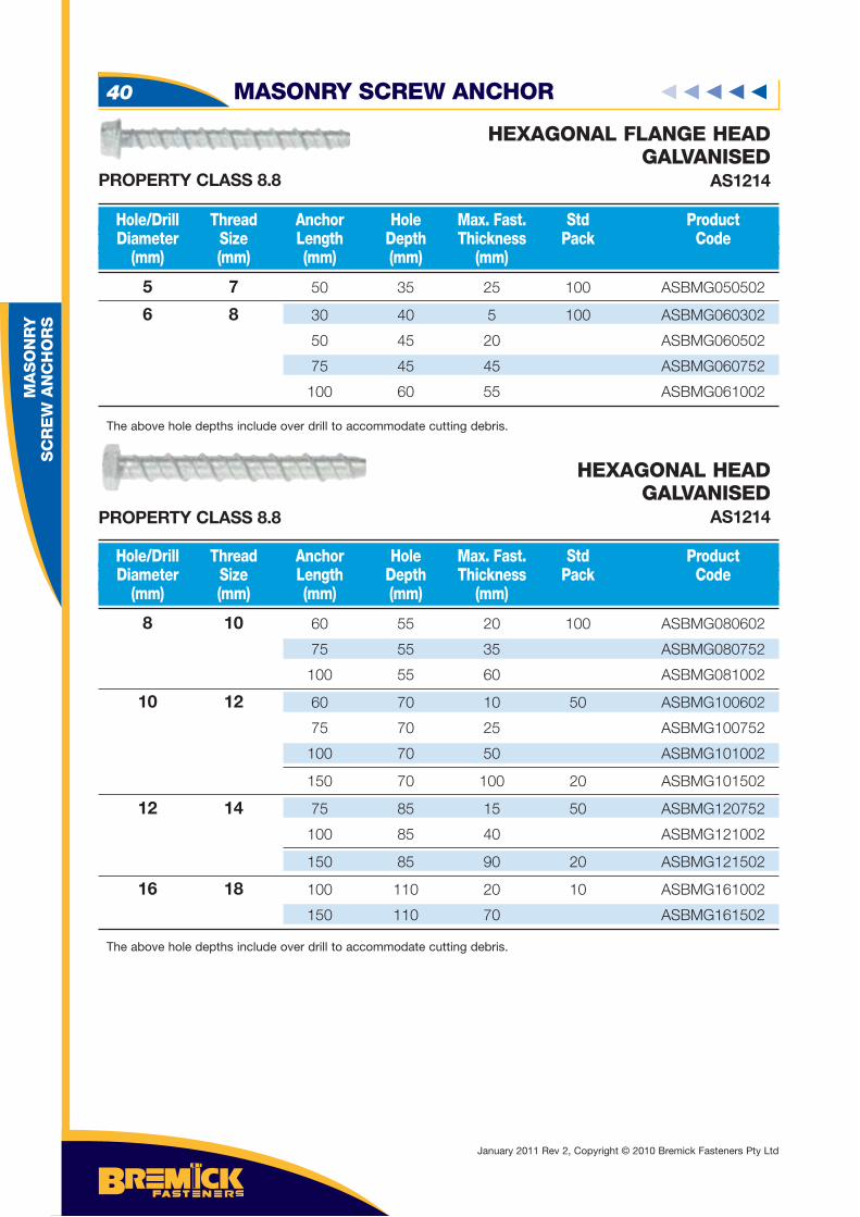
5 7 50 35 25 100 ASBMG050502
6 8 30 40 5 100 ASBMG060302
50 45 20 ASBMG060502
75 45 45 ASBMG060752
100 60 55 ASBMG061002
Hole/Drill Thread Anchor Hole Max. Fast. Std Product Diameter Size Length Depth Thickness Pack Code (mm) (mm) (mm) (mm) (mm)
HEXAGONAL FLANGE HEADGALVANISED
AS1214
8 10 60 55 20 100 ASBMG080602
75 55 35 ASBMG080752
100 55 60 ASBMG081002
10 12 60 70 10 50 ASBMG100602
75 70 25 ASBMG100752
100 70 50 ASBMG101002
150 70 100 20 ASBMG101502
12 14 75 85 15 50 ASBMG120752
100 85 40 ASBMG121002
150 85 90 20 ASBMG121502
16 18 100 110 20 10 ASBMG161002
150 110 70 ASBMG161502
Hole/Drill Thread Anchor Hole Max. Fast. Std Product Diameter Size Length Depth Thickness Pack Code (mm) (mm) (mm) (mm) (mm)
HEXAGONAL HEADGALVANISED
AS1214
The above hole depths include over drill to accommodate cutting debris.
The above hole depths include over drill to accommodate cutting debris.
PROPERTY CLASS 8.8
PROPERTY CLASS 8.8
January 2011 Rev 2, Copyright © 2010 Bremick Fasteners Pty Ltd
MASONRY SCREW ANCHOR 41
MA
SO
NR
Y
SC
RE
W A
NC
HO
RS
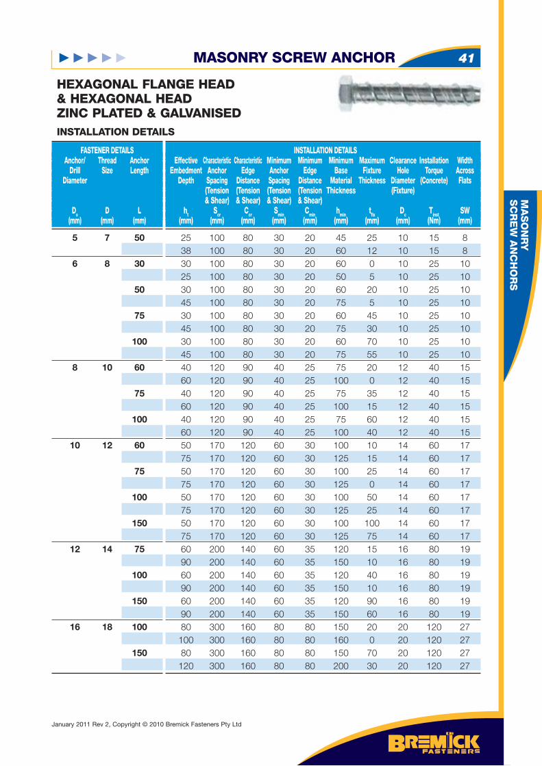
5 7 50 6 8 30 50 75 100 8 10 60 75 100 10 12 60 75 100 150 12 14 75 100 150 16 18 100 150
FASTENER DETAILS Anchor/ Thread Anchor Drill Size Length Diameter
Do D L (mm) (mm) (mm)
HEXAGONAL FLANGE HEAD& HEXAGONAL HEADZINC PLATED & GALVANISED
INSTALLATION DETAILS Effective Characteristic Characteristic Minimum Minimum Minimum Maximum Clearance Installation Width Embedment Anchor Edge Anchor Edge Base Fixture Hole Torque Across Depth Spacing Distance Spacing Distance Material Thickness Diameter (Concrete) Flats (Tension (Tension (Tension (Tension Thickness (Fixture) & Shear) & Shear) & Shear) & Shear) ht Scr Ccr Smin Cmin hmin tfi x Dc Tinst SW (mm) (mm) (mm) (mm) (mm) (mm) (mm) (mm) (Nm) (mm)
INSTALLATION DETAILS
25 100 80 30 20 45 25 10 15 8 38 100 80 30 20 60 12 10 15 8 30 100 80 30 20 60 0 10 25 10 25 100 80 30 20 50 5 10 25 10 30 100 80 30 20 60 20 10 25 10 45 100 80 30 20 75 5 10 25 10 30 100 80 30 20 60 45 10 25 10 45 100 80 30 20 75 30 10 25 10 30 100 80 30 20 60 70 10 25 10 45 100 80 30 20 75 55 10 25 10 40 120 90 40 25 75 20 12 40 15 60 120 90 40 25 100 0 12 40 15 40 120 90 40 25 75 35 12 40 15 60 120 90 40 25 100 15 12 40 15 40 120 90 40 25 75 60 12 40 15 60 120 90 40 25 100 40 12 40 15 50 170 120 60 30 100 10 14 60 17 75 170 120 60 30 125 15 14 60 17 50 170 120 60 30 100 25 14 60 17 75 170 120 60 30 125 0 14 60 17 50 170 120 60 30 100 50 14 60 17 75 170 120 60 30 125 25 14 60 17 50 170 120 60 30 100 100 14 60 17 75 170 120 60 30 125 75 14 60 17 60 200 140 60 35 120 15 16 80 19 90 200 140 60 35 150 10 16 80 19 60 200 140 60 35 120 40 16 80 19 90 200 140 60 35 150 10 16 80 19 60 200 140 60 35 120 90 16 80 19 90 200 140 60 35 150 60 16 80 19 80 300 160 80 80 150 20 20 120 27 100 300 160 80 80 160 0 20 120 27 80 300 160 80 80 150 70 20 120 27 120 300 160 80 80 200 30 20 120 27
January 2011 Rev 2, Copyright © 2010 Bremick Fasteners Pty Ltd
MA
SO
NR
Y
SC
RE
W A
NC
HO
RS
MASONRY SCREW ANCHOR42
HEXAGONAL FLANGE HEAD& HEXAGONAL HEAD
ZINC PLATED & GALVANISED
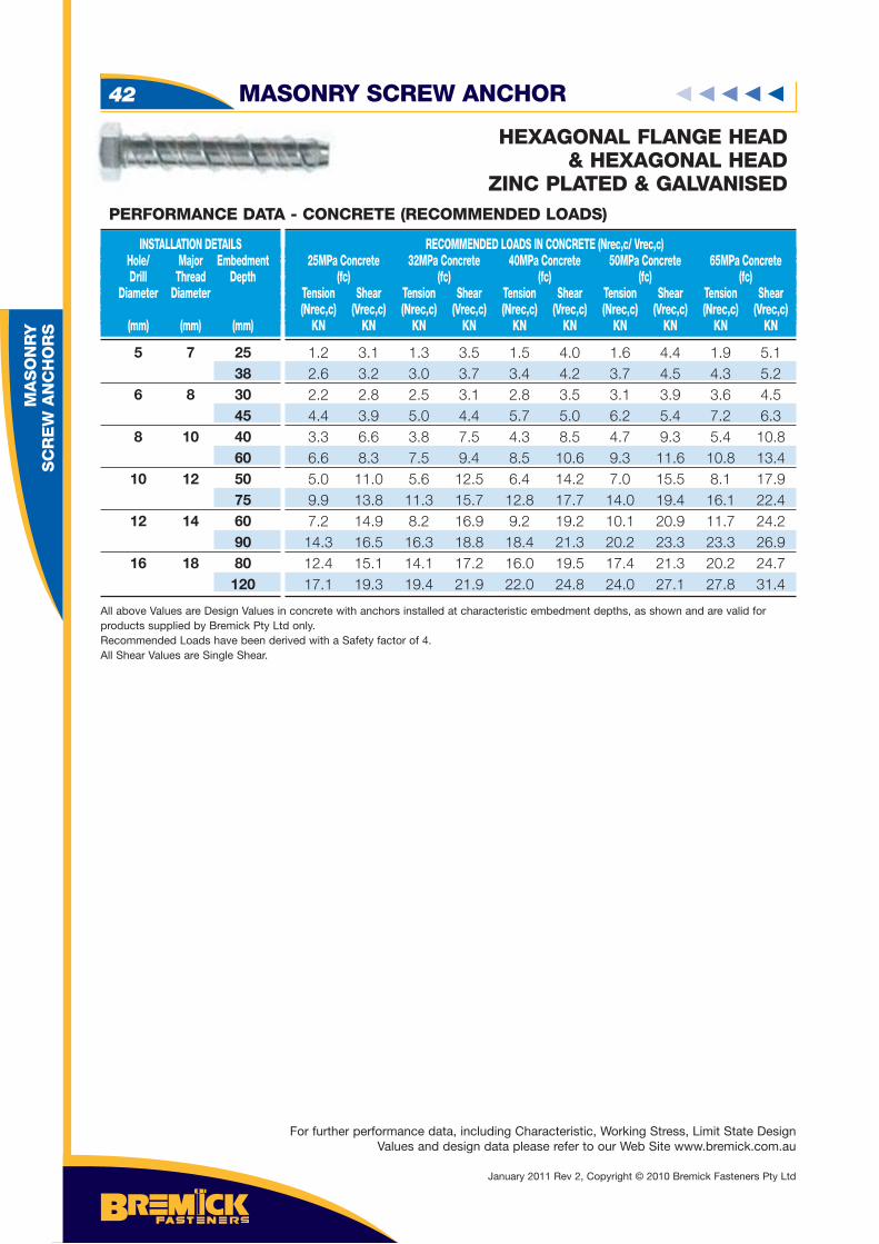
5 7 25 38 6 8 30 45 8 10 40 60 10 12 50 75 12 14 60 90 16 18 80 120
INSTALLATION DETAILS Hole/ Major Embedment Drill Thread Depth Diameter Diameter (mm) (mm) (mm)
RECOMMENDED LOADS IN CONCRETE (Nrec,c/ Vrec,c) 25MPa Concrete 32MPa Concrete 40MPa Concrete 50MPa Concrete 65MPa Concrete (fc) (fc) (fc) (fc) (fc) Tension Shear Tension Shear Tension Shear Tension Shear Tension Shear (Nrec,c) (Vrec,c) (Nrec,c) (Vrec,c) (Nrec,c) (Vrec,c) (Nrec,c) (Vrec,c) (Nrec,c) (Vrec,c) KN KN KN KN KN KN KN KN KN KN
1.2 3.1 1.3 3.5 1.5 4.0 1.6 4.4 1.9 5.1 2.6 3.2 3.0 3.7 3.4 4.2 3.7 4.5 4.3 5.2 2.2 2.8 2.5 3.1 2.8 3.5 3.1 3.9 3.6 4.5 4.4 3.9 5.0 4.4 5.7 5.0 6.2 5.4 7.2 6.3 3.3 6.6 3.8 7.5 4.3 8.5 4.7 9.3 5.4 10.8 6.6 8.3 7.5 9.4 8.5 10.6 9.3 11.6 10.8 13.4 5.0 11.0 5.6 12.5 6.4 14.2 7.0 15.5 8.1 17.9 9.9 13.8 11.3 15.7 12.8 17.7 14.0 19.4 16.1 22.4 7.2 14.9 8.2 16.9 9.2 19.2 10.1 20.9 11.7 24.2 14.3 16.5 16.3 18.8 18.4 21.3 20.2 23.3 23.3 26.9 12.4 15.1 14.1 17.2 16.0 19.5 17.4 21.3 20.2 24.7 17.1 19.3 19.4 21.9 22.0 24.8 24.0 27.1 27.8 31.4
All above Values are Design Values in concrete with anchors installed at characteristic embedment depths, as shown and are valid for products supplied by Bremick Pty Ltd only. Recommended Loads have been derived with a Safety factor of 4.All Shear Values are Single Shear.
PERFORMANCE DATA - CONCRETE (RECOMMENDED LOADS)
For further performance data, including Characteristic, Working Stress, Limit State Design Values and design data please refer to our Web Site www.bremick.com.au
January 2011 Rev 2, Copyright © 2010 Bremick Fasteners Pty Ltd
BR
EM
FIX
™ C
HE
MIC
AL A
NC
HO
RS
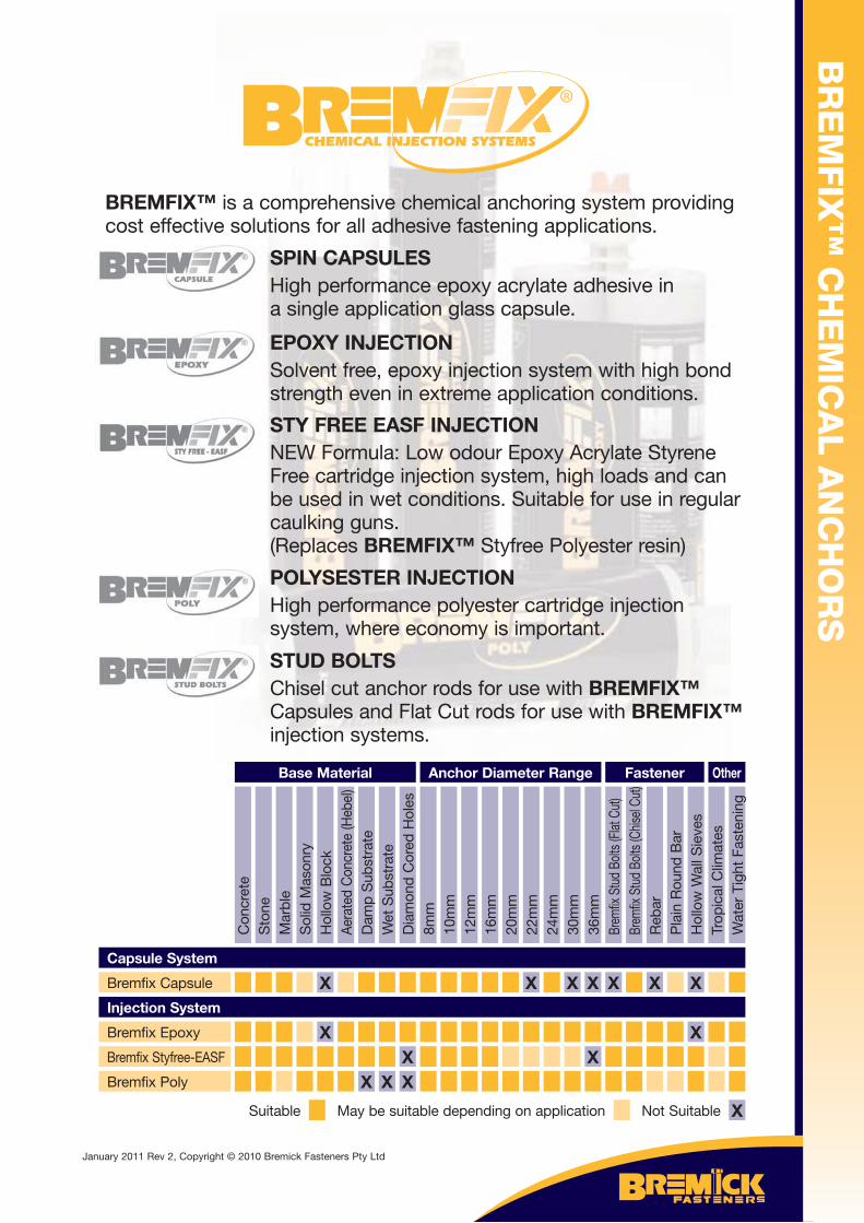
BREMFIX™ is a comprehensive chemical anchoring system providing cost effective solutions for all adhesive fastening applications.
SPIN CAPSULESHigh performance epoxy acrylate adhesive in a single application glass capsule.
EPOXY INJECTIONSolvent free, epoxy injection system with high bond strength even in extreme application conditions.
STY FREE EASF INJECTIONNEW Formula: Low odour Epoxy Acrylate Styrene Free cartridge injection system, high loads and can be used in wet conditions. Suitable for use in regular caulking guns.(Replaces BREMFIX™ Styfree Polyester resin)
POLYSESTER INJECTIONHigh performance polyester cartridge injection system, where economy is important.
STUD BOLTSChisel cut anchor rods for use with BREMFIX™ Capsules and Flat Cut rods for use with BREMFIX™ injection systems.
Capsule System
Bremfix Capsule
Injection System
Bremfix Epoxy
Bremfix Styfree-EASF
Bremfix Poly
Con
cret
eS
tone
Mar
ble
Sol
id M
ason
ryH
ollo
w B
lock
Aera
ted
Con
cret
e (H
ebel
)
X
X
Dam
p S
ubst
rate
X
Wet
Sub
stra
te
X
Dia
mon
d C
ored
Hol
es
XX
8mm
10m
m12
mm
16m
m20
mm
22m
m
X
24m
m30
mm
X
36m
m
X
X
Brem
fix S
tud
Bolts
(Flat
Cut
)
X
Brem
fix S
tud
Bolts
(Chis
el Cu
t)R
ebar
X
Pla
in R
ound
Bar
Hol
low
Wal
l Sie
ves
X
X
Trop
ical
Clim
ates
Wat
er T
ight
Fas
teni
ng
Base Material Anchor Diameter Range Fastener Other
Not Suitable XMay be suitable depending on applicationSuitable
January 2011 Rev 2, Copyright © 2010 Bremick Fasteners Pty Ltd
BR
EM
FIX
™ C
AP
SU
LE
SY
ST
EM
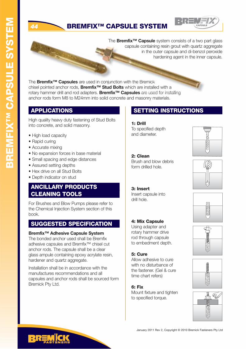
The Bremfix™ Capsule system consists of a two part glass capsule containing resin grout with quartz aggregate
in the outer capsule and di-benzol peroxide hardening agent in the inner capsule.
The Bremfix™ Capsules are used in conjunction with the Bremick chisel pointed anchor rods, Bremfix™ Stud Bolts which are installed with a rotary hammer drill and rod adapters. Bremfix™ Capsules are used for installing anchor rods form M8 to M24mm into solid concrete and masonry materials.
APPLICATIONS
High quality heavy duty fastening of Stud Bolts into concrete, and solid masonry.
• High load capacity• Rapid curing• Accurate mixing• No expansion forces in base material • Small spacing and edge distances• Assured setting depths • Hex drive on all Stud Bolts• Depth indicator on stud
ANCILLARY PRODUCTSCLEANING TOOLS
For Brushes and Blow Pumps please refer to the Chemical Injection System section of this book.
SUGGESTED SPECIFICATION
Bremfix™ Adhesive Capsule SystemThe bonded anchor used shall be Bremfix adhesive capsules and Bremfix™ chisel cut anchor rods. The capsule shall be a clear glass ampule containing epoxy acrylate resin, hardener and quartz aggregate.
Installation shall be in accordance with the manufactures recommendations and all capsules and anchor rods shall be sourced form Bremick Pty Ltd.
SETTING INSTRUCTIONS
1: DrillTo specified depthand diameter.
2: CleanBrush and blow debrisform drilled hole.
3: InsertInsert capsule intodrill hole.
4: Mix CapsuleUsing adapter and rotary hammer drive rod through capsule to embedment depth.
5: CureAllow adhesive to cure with no disturbance of the fastener. (Gel & cure time chart refers)
6: FixMount fixture and tightento specified torque.
Th
in conjunction with the Bremick x™ Stud Bolts which are installed with as Bremfix™ Capsules are used for installing
capsule containing resin grout with quartz ain the outer capsule and di-benzol
hardening agent in the innerh
kh a
BREMFIX™ CAPSULE SYSTEM44
January 2011 Rev 2, Copyright © 2010 Bremick Fasteners Pty Ltd
CHEMICAL CAPSULE 45
CH
EM
ICA
L A
NC
HO
RS
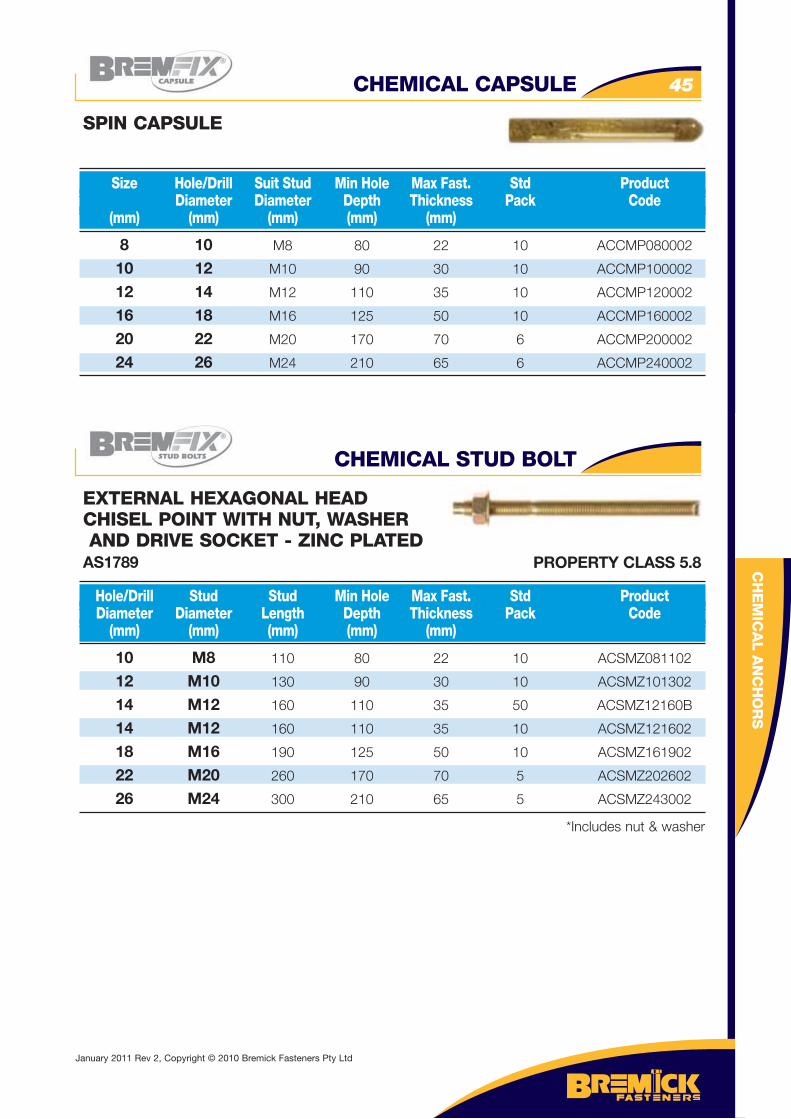
8 10 M8 80 22 10 ACCMP080002
10 12 M10 90 30 10 ACCMP100002
12 14 M12 110 35 10 ACCMP120002
16 18 M16 125 50 10 ACCMP160002
20 22 M20 170 70 6 ACCMP200002
24 26 M24 210 65 6 ACCMP240002
Size Hole/Drill Suit Stud Min Hole Max Fast. Std Product Diameter Diameter Depth Thickness Pack Code (mm) (mm) (mm) (mm) (mm)
SPIN CAPSULE
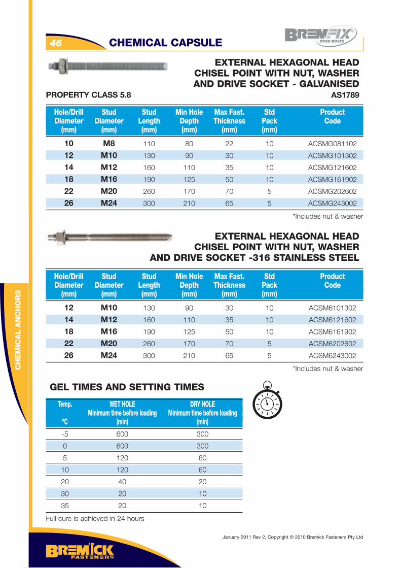
10 M8 110 80 22 10 ACSMZ081102
12 M10 130 90 30 10 ACSMZ101302
14 M12 160 110 35 50 ACSMZ12160B
14 M12 160 110 35 10 ACSMZ121602
18 M16 190 125 50 10 ACSMZ161902
22 M20 260 170 70 5 ACSMZ202602
26 M24 300 210 65 5 ACSMZ243002
*Includes nut & washer
Hole/Drill Stud Stud Min Hole Max Fast. Std Product Diameter Diameter Length Depth Thickness Pack Code (mm) (mm) (mm) (mm) (mm)
EXTERNAL HEXAGONAL HEADCHISEL POINT WITH NUT, WASHER AND DRIVE SOCKET - ZINC PLATEDAS1789
CHEMICAL STUD BOLT
PROPERTY CLASS 5.8
January 2011 Rev 2, Copyright © 2010 Bremick Fasteners Pty Ltd
CH
EM
ICA
L A
NC
HO
RS
CHEMICAL CAPSULE46
10 M8 110 80 22 10 ACSMG081102
12 M10 130 90 30 10 ACSMG101302
14 M12 160 110 35 10 ACSMG121602
18 M16 190 125 50 10 ACSMG161902
22 M20 260 170 70 5 ACSMG202602
26 M24 300 210 65 5 ACSMG243002
*Includes nut & washer
Hole/Drill Stud Stud Min Hole Max Fast. Std Product Diameter Diameter Length Depth Thickness Pack Code (mm) (mm) (mm) (mm) (mm) (mm)
EXTERNAL HEXAGONAL HEADCHISEL POINT WITH NUT, WASHERAND DRIVE SOCKET - GALVANISED
AS1789
12 M10 130 90 30 10 ACSM6101302
14 M12 160 110 35 10 ACSM6121602
18 M16 190 125 50 10 ACSM6161902
22 M20 260 170 70 5 ACSM6202602
26 M24 300 210 65 5 ACSM6243002
*Includes nut & washer
Hole/Drill Stud Stud Min Hole Max Fast. Std Product Diameter Diameter Length Depth Thickness Pack Code (mm) (mm) (mm) (mm) (mm) (mm)
EXTERNAL HEXAGONAL HEADCHISEL POINT WITH NUT, WASHER
AND DRIVE SOCKET -316 STAINLESS STEEL
-5 600 300
0 600 300
5 120 60
10 120 60
20 40 20
30 20 10
35 20 10
Full cure is achieved in 24 hours
Temp. WET HOLE DRY HOLE Minimum time before loading Minimum time before loading ºC (min) (min)
GEL TIMES AND SETTING TIMES
PROPERTY CLASS 5.8
January 2011 Rev 2, Copyright © 2010 Bremick Fasteners Pty Ltd
BREMFIX™ CAPSULE SYSTEM 47
CH
EM
ICA
L A
NC
HO
RS
10 M8 110
12 M10 130
14 M12 160
18 M16 190
22 M20 260
26 M24 300
FASTENER DETAILS Anchor/ Thread Anchor Drill Size Length Diameter
Do D L (mm) (mm) (mm)
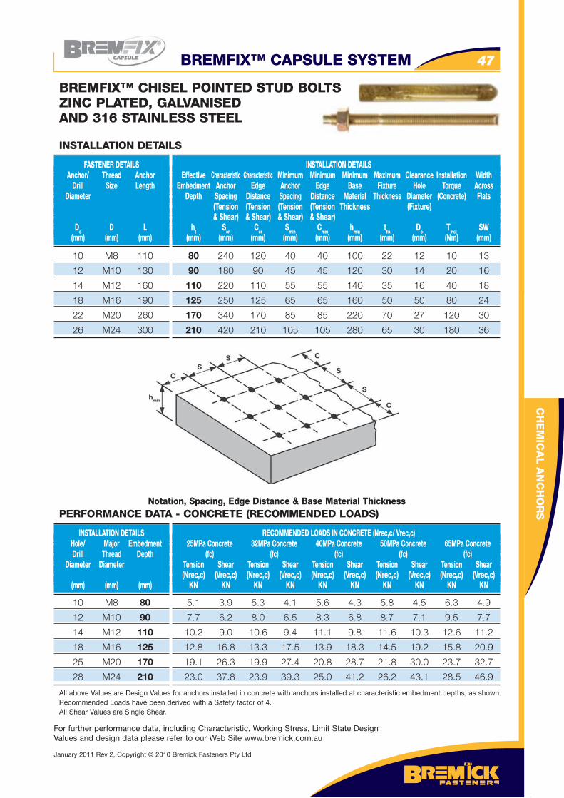
BREMFIX™ CHISEL POINTED STUD BOLTSZINC PLATED, GALVANISED AND 316 STAINLESS STEEL
INSTALLATION DETAILS Effective Characteristic Characteristic Minimum Minimum Minimum Maximum Clearance Installation Width Embedment Anchor Edge Anchor Edge Base Fixture Hole Torque Across Depth Spacing Distance Spacing Distance Material Thickness Diameter (Concrete) Flats (Tension (Tension (Tension (Tension Thickness (Fixture) & Shear) & Shear) & Shear) & Shear) ht Scr Ccr Smin Cmin hmin tfi x Dc Tinst SW (mm) (mm) (mm) (mm) (mm) (mm) (mm) (mm) (Nm) (mm)
INSTALLATION DETAILS
80 240 120 40 40 100 22 12 10 13
90 180 90 45 45 120 30 14 20 16
110 220 110 55 55 140 35 16 40 18
125 250 125 65 65 160 50 50 80 24
170 340 170 85 85 220 70 27 120 30
210 420 210 105 105 280 65 30 180 36
Notation, Spacing, Edge Distance & Base Material Thickness
10 M8 80
12 M10 90
14 M12 110
18 M16 125
25 M20 170
28 M24 210
INSTALLATION DETAILS Hole/ Major Embedment Drill Thread Depth Diameter Diameter (mm) (mm) (mm)
RECOMMENDED LOADS IN CONCRETE (Nrec,c/ Vrec,c) 25MPa Concrete 32MPa Concrete 40MPa Concrete 50MPa Concrete 65MPa Concrete (fc) (fc) (fc) (fc) (fc) Tension Shear Tension Shear Tension Shear Tension Shear Tension Shear (Nrec,c) (Vrec,c) (Nrec,c) (Vrec,c) (Nrec,c) (Vrec,c) (Nrec,c) (Vrec,c) (Nrec,c) (Vrec,c) KN KN KN KN KN KN KN KN KN KN
5.1 3.9 5.3 4.1 5.6 4.3 5.8 4.5 6.3 4.9
7.7 6.2 8.0 6.5 8.3 6.8 8.7 7.1 9.5 7.7
10.2 9.0 10.6 9.4 11.1 9.8 11.6 10.3 12.6 11.2
12.8 16.8 13.3 17.5 13.9 18.3 14.5 19.2 15.8 20.9
19.1 26.3 19.9 27.4 20.8 28.7 21.8 30.0 23.7 32.7
23.0 37.8 23.9 39.3 25.0 41.2 26.2 43.1 28.5 46.9
All above Values are Design Values for anchors installed in concrete with anchors installed at characteristic embedment depths, as shown. Recommended Loads have been derived with a Safety factor of 4.All Shear Values are Single Shear.
PERFORMANCE DATA - CONCRETE (RECOMMENDED LOADS)
For further performance data, including Characteristic, Working Stress, Limit State Design Values and design data please refer to our Web Site www.bremick.com.au
January 2011 Rev 2, Copyright © 2010 Bremick Fasteners Pty Ltd
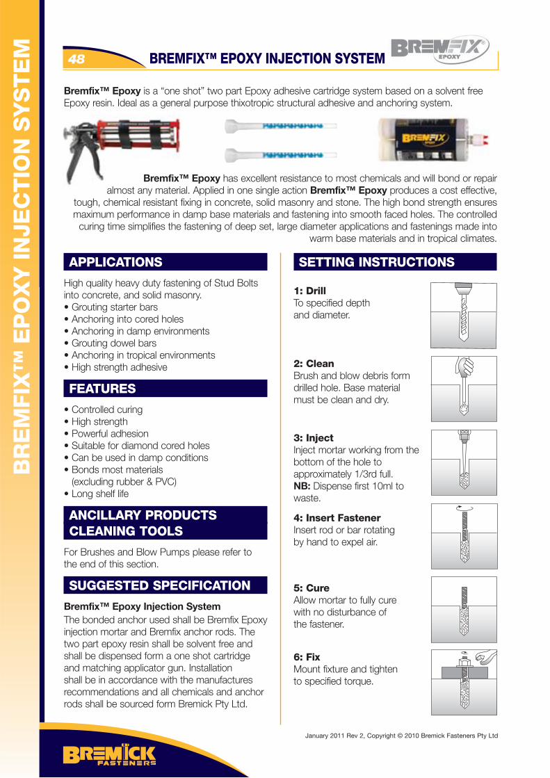
BREMFIX™ EPOXY INJECTION SYSTEM48
APPLICATIONS
High quality heavy duty fastening of Stud Bolts into concrete, and solid masonry.• Grouting starter bars• Anchoring into cored holes• Anchoring in damp environments• Grouting dowel bars• Anchoring in tropical environments• High strength adhesive
FEATURES
• Controlled curing• High strength• Powerful adhesion• Suitable for diamond cored holes • Can be used in damp conditions• Bonds most materials (excluding rubber & PVC) • Long shelf life
ANCILLARY PRODUCTSCLEANING TOOLS
For Brushes and Blow Pumps please refer to the end of this section.
SUGGESTED SPECIFICATION
Bremfix™ Epoxy Injection SystemThe bonded anchor used shall be Bremfix Epoxy injection mortar and Bremfix anchor rods. The two part epoxy resin shall be solvent free and shall be dispensed form a one shot cartridge and matching applicator gun. Installation shall be in accordance with the manufactures recommendations and all chemicals and anchor rods shall be sourced form Bremick Pty Ltd.
SETTING INSTRUCTIONS
1: DrillTo specified depthand diameter.
2: CleanBrush and blow debris form drilled hole. Base material must be clean and dry.
3: InjectInject mortar working from the bottom of the hole toapproximately 1/3rd full.NB: Dispense first 10ml towaste.
4: Insert FastenerInsert rod or bar rotatingby hand to expel air.
5: CureAllow mortar to fully cure with no disturbance of the fastener.
6: FixMount fixture and tightento specified torque.
Bremfix™ Epoxy is a “one shot” two part Epoxy adhesive cartridge system based on a solvent free Epoxy resin. Ideal as a general purpose thixotropic structural adhesive and anchoring system.
Bremfix™ Epoxy has excellent resistance to most chemicals and will bond or repairalmost any material. Applied in one single action Bremfix™ Epoxy produces a cost effective,
tough, chemical resistant fixing in concrete, solid masonry and stone. The high bond strength ensures maximum performance in damp base materials and fastening into smooth faced holes. The controlled
curing time simplifies the fastening of deep set, large diameter applications and fastenings made into warm base materials and in tropical climates.
BR
EM
FIX
™ E
PO
XY
IN
JEC
TIO
N S
YS
TE
M
January 2011 Rev 2, Copyright © 2010 Bremick Fasteners Pty Ltd
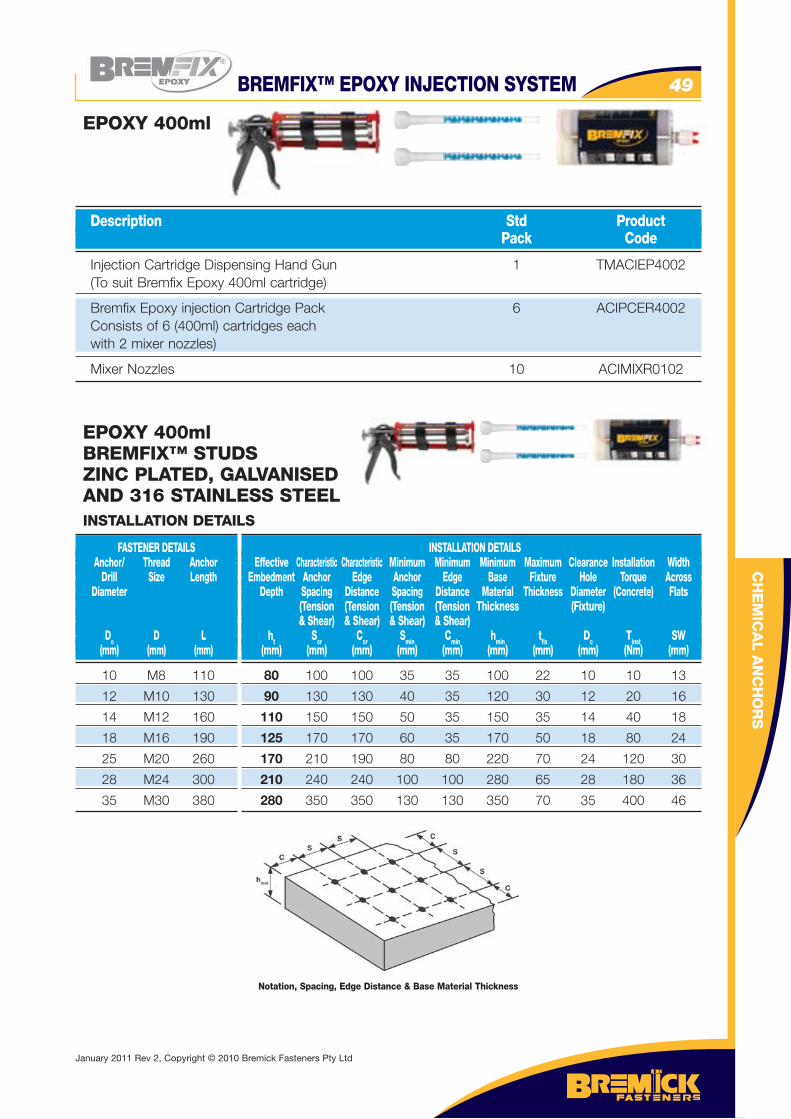
BREMFIX™ EPOXY INJECTION SYSTEM 49
CH
EM
ICA
L A
NC
HO
RS
Injection Cartridge Dispensing Hand Gun 1 TMACIEP4002 (To suit Bremfix Epoxy 400ml cartridge)
Bremfix Epoxy injection Cartridge Pack 6 ACIPCER4002 Consists of 6 (400ml) cartridges each with 2 mixer nozzles)
Mixer Nozzles 10 ACIMIXR0102
Description Std Product Pack Code
EPOXY 400ml
EPOXY 400mlBREMFIX™ STUDSZINC PLATED, GALVANISEDAND 316 STAINLESS STEEL
10 M8 110
12 M10 130
14 M12 160
18 M16 190
25 M20 260
28 M24 300
35 M30 380
FASTENER DETAILS Anchor/ Thread Anchor Drill Size Length Diameter
Do D L (mm) (mm) (mm)
INSTALLATION DETAILS Effective Characteristic Characteristic Minimum Minimum Minimum Maximum Clearance Installation Width Embedment Anchor Edge Anchor Edge Base Fixture Hole Torque Across Depth Spacing Distance Spacing Distance Material Thickness Diameter (Concrete) Flats (Tension (Tension (Tension (Tension Thickness (Fixture) & Shear) & Shear) & Shear) & Shear) ht Scr Ccr Smin Cmin hmin tfi x Dc Tinst SW (mm) (mm) (mm) (mm) (mm) (mm) (mm) (mm) (Nm) (mm)
INSTALLATION DETAILS
80 100 100 35 35 100 22 10 10 13
90 130 130 40 35 120 30 12 20 16
110 150 150 50 35 150 35 14 40 18
125 170 170 60 35 170 50 18 80 24
170 210 190 80 80 220 70 24 120 30
210 240 240 100 100 280 65 28 180 36
280 350 350 130 130 350 70 35 400 46
Notation, Spacing, Edge Distance & Base Material Thickness
January 2011 Rev 2, Copyright © 2010 Bremick Fasteners Pty Ltd
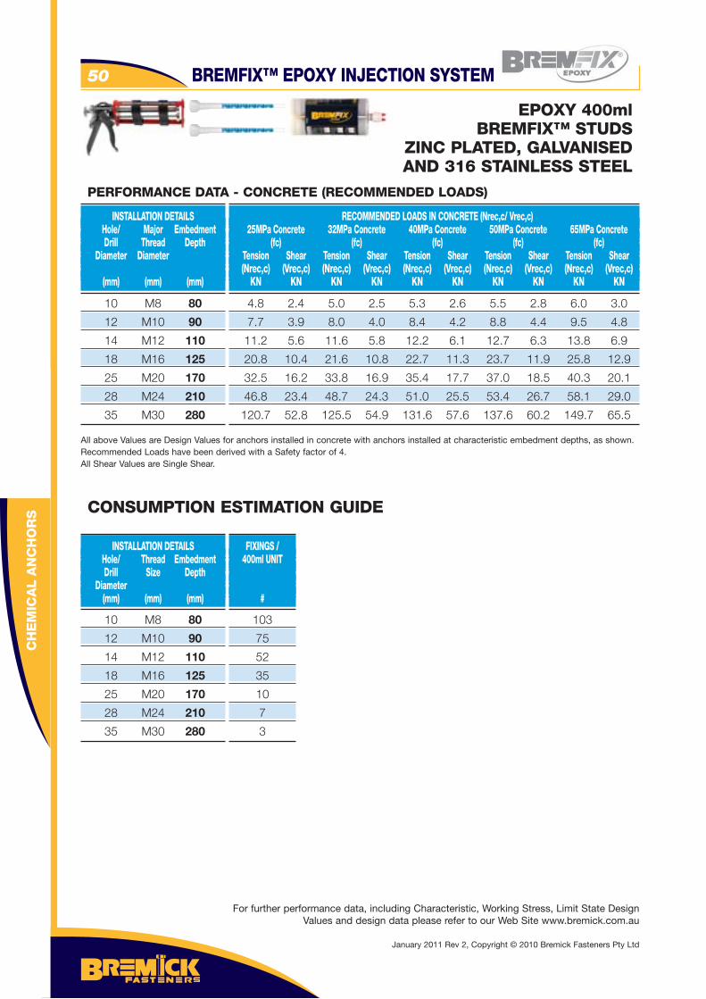
BREMFIX™ EPOXY INJECTION SYSTEM50
CH
EM
ICA
L A
NC
HO
RS
EPOXY 400mlBREMFIX™ STUDS
ZINC PLATED, GALVANISEDAND 316 STAINLESS STEEL
10 M8 80
12 M10 90
14 M12 110
18 M16 125
25 M20 170
28 M24 210
35 M30 280
INSTALLATION DETAILS Hole/ Major Embedment Drill Thread Depth Diameter Diameter (mm) (mm) (mm)
RECOMMENDED LOADS IN CONCRETE (Nrec,c/ Vrec,c) 25MPa Concrete 32MPa Concrete 40MPa Concrete 50MPa Concrete 65MPa Concrete (fc) (fc) (fc) (fc) (fc) Tension Shear Tension Shear Tension Shear Tension Shear Tension Shear (Nrec,c) (Vrec,c) (Nrec,c) (Vrec,c) (Nrec,c) (Vrec,c) (Nrec,c) (Vrec,c) (Nrec,c) (Vrec,c) KN KN KN KN KN KN KN KN KN KN
PERFORMANCE DATA - CONCRETE (RECOMMENDED LOADS)
4.8 2.4 5.0 2.5 5.3 2.6 5.5 2.8 6.0 3.0
7.7 3.9 8.0 4.0 8.4 4.2 8.8 4.4 9.5 4.8
11.2 5.6 11.6 5.8 12.2 6.1 12.7 6.3 13.8 6.9
20.8 10.4 21.6 10.8 22.7 11.3 23.7 11.9 25.8 12.9
32.5 16.2 33.8 16.9 35.4 17.7 37.0 18.5 40.3 20.1
46.8 23.4 48.7 24.3 51.0 25.5 53.4 26.7 58.1 29.0
120.7 52.8 125.5 54.9 131.6 57.6 137.6 60.2 149.7 65.5
All above Values are Design Values for anchors installed in concrete with anchors installed at characteristic embedment depths, as shown. Recommended Loads have been derived with a Safety factor of 4.All Shear Values are Single Shear.
For further performance data, including Characteristic, Working Stress, Limit State Design Values and design data please refer to our Web Site www.bremick.com.au
10 M8 80
12 M10 90
14 M12 110
18 M16 125
25 M20 170
28 M24 210
35 M30 280
INSTALLATION DETAILS Hole/ Thread Embedment Drill Size Depth Diameter (mm) (mm) (mm)
FIXINGS / 400ml UNIT
#
CONSUMPTION ESTIMATION GUIDE
103
75
52
35
10
7
3
January 2011 Rev 2, Copyright © 2010 Bremick Fasteners Pty Ltd
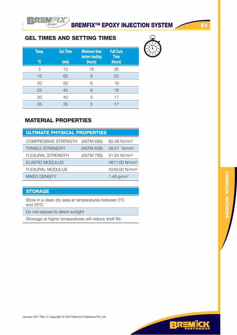
BREMFIX™ EPOXY INJECTION SYSTEM 51
CH
EM
ICA
L A
NC
HO
RS
5 15 18 36
15 60 8 20
20 50 6 18
25 45 6 18
30 40 5 17
35 35 5 17
Temp. Gel Time Minimum time Full Cure before loading Time ºC (min) (hours) (hours)
GEL TIMES AND SETTING TIMES
COMPRESSIVE STRENGTH (ASTM 695) 82.48 N/mm2
TENSILE STRENGTH (ASTM 638) 28.21 N/mm2
FLEXURAL STRENGTH (ASTM 795) 41.64 N/mm2
ELASTIC MODULUS 4811.00 N/mm2
FLEXURAL MODULUS 4249.00 N/mm2
MIXED DENSITY 1.40 g/cm3
ULTIMATE PHYSICAL PROPERTIES
MATERIAL PROPERTIES
Store in a clean dry area at temperatures between 5ºC and 25ºC.
Do not expose to direct sunlight.
Storeage at higher temperatures will reduce shelf life.
STORAGE
January 2011 Rev 2, Copyright © 2010 Bremick Fasteners Pty Ltd
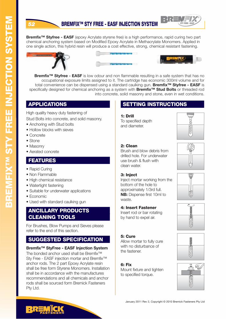
BREMFIX™ STY FREE - EASF INJECTION SYSTEM52
APPLICATIONS
High quality heavy duty fastening of Stud Bolts into concrete, and solid masonry.• Anchoring with Stud bolts• Hollow blocks with sieves• Concrete • Stone• Masonry• Aerated concrete
FEATURES
• Rapid Curing• Non Flammable• High chemical resistance• Watertight fastening• Suitable for underwater applications• Economic• Used with standard caulking gun
ANCILLARY PRODUCTSCLEANING TOOLS
For Brushes, Blow Pumps and Sieves please refer to the end of this section.
SUGGESTED SPECIFICATION
Bremfix™ StyFree - EASF Injection SystemThe bonded anchor used shall be Bremfix™ Sty Free - EASF injection mortar and Bremfix™ anchor rods. The 2 part Epoxy Acrylate resin shall be free form Styrene Monomers. Installation shall be in accordance with the manufactures recommendations and all chemicals and anchor rods shall be sourced form Bremick Fasteners Pty Ltd.
SETTING INSTRUCTIONS
1: DrillTo specified depthand diameter.
2: CleanBrush and blow debris fromdrilled hole. For underwateruse brush & flush withclean water.
3: InjectInject mortar working from the bottom of the hole toapproximately 1/3rd full.NB: Dispense first 10ml towaste.
4: Insert FastenerInsert rod or bar rotatingby hand to expel air.
5: CureAllow mortar to fully cure with no disturbance of the fastener.
6: FixMount fixture and tightento specified torque.
Bremfix™ Styfree - EASF (epoxy Acrylate styrene free) is a high performance, rapid curing two part chemical anchoring system based on Modified Epoxy Acrylate in Methacrylate Monomers. Applied in one single action, this hybrid resin will produce a cost effective, strong, chemical resistant fastening.
Bremfix™ Styfree - EASF is low odour and non flammable resulting in a safe system that has no occupational exposure limits assigned to it. The cartridge has economic 300ml volume and for
total convenience can be dispensed using a standard caulking gun. Bremfix™ Styfree - EASF is specifically designed for chemical anchoring as a system with Bremfix™ Stud Bolts or threaded rod
into concrete, solid masonry and stone, even in wet conditions.
BR
EM
FIX
™ S
TY
FR
EE
IN
JEC
TIO
N S
YS
TE
M
January 2011 Rev 2, Copyright © 2010 Bremick Fasteners Pty Ltd
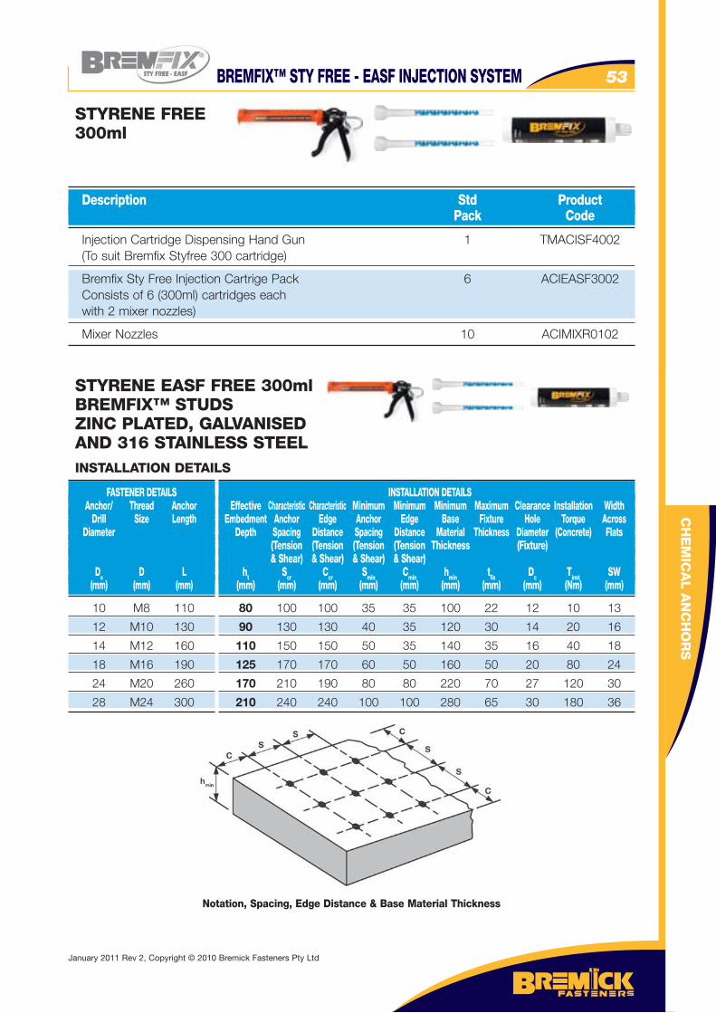
BREMFIX™ STY FREE - EASF INJECTION SYSTEM 53
CH
EM
ICA
L A
NC
HO
RS
Injection Cartridge Dispensing Hand Gun 1 TMACISF4002 (To suit Bremfix Styfree 300 cartridge)
Bremfix Sty Free Injection Cartrige Pack 6 ACIEASF3002 Consists of 6 (300ml) cartridges each with 2 mixer nozzles)
Mixer Nozzles 10 ACIMIXR0102
Description Std Product Pack Code
STYRENE FREE300ml
STYRENE EASF FREE 300mlBREMFIX™ STUDSZINC PLATED, GALVANISEDAND 316 STAINLESS STEEL
10 M8 110
12 M10 130
14 M12 160
18 M16 190
24 M20 260
28 M24 300
FASTENER DETAILS Anchor/ Thread Anchor Drill Size Length Diameter
Do D L (mm) (mm) (mm)
INSTALLATION DETAILS Effective Characteristic Characteristic Minimum Minimum Minimum Maximum Clearance Installation Width Embedment Anchor Edge Anchor Edge Base Fixture Hole Torque Across Depth Spacing Distance Spacing Distance Material Thickness Diameter (Concrete) Flats (Tension (Tension (Tension (Tension Thickness (Fixture) & Shear) & Shear) & Shear) & Shear) ht Scr Ccr Smin Cmin hmin tfi x Dc Tinst SW (mm) (mm) (mm) (mm) (mm) (mm) (mm) (mm) (Nm) (mm)
INSTALLATION DETAILS
80 100 100 35 35 100 22 12 10 13
90 130 130 40 35 120 30 14 20 16
110 150 150 50 35 140 35 16 40 18
125 170 170 60 50 160 50 20 80 24
170 210 190 80 80 220 70 27 120 30
210 240 240 100 100 280 65 30 180 36
Notation, Spacing, Edge Distance & Base Material Thickness
January 2011 Rev 2, Copyright © 2010 Bremick Fasteners Pty Ltd
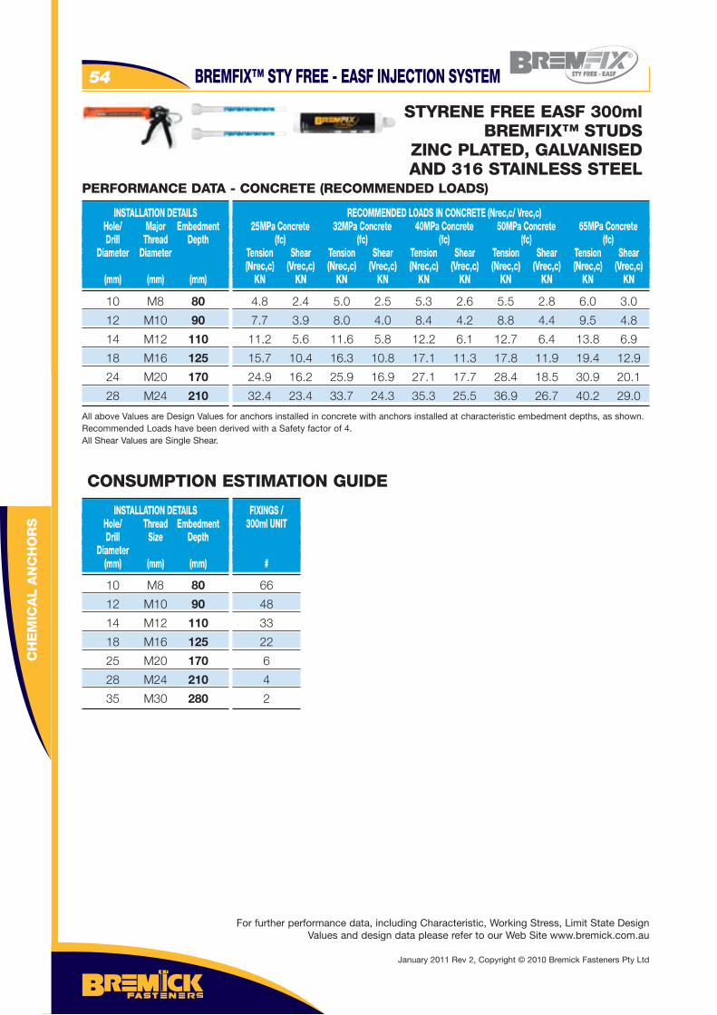
CH
EM
ICA
L A
NC
HO
RS
BREMFIX™ STY FREE - EASF INJECTION SYSTEM54
10 M8 80
12 M10 90
14 M12 110
18 M16 125
25 M20 170
28 M24 210
35 M30 280
INSTALLATION DETAILS Hole/ Thread Embedment Drill Size Depth Diameter (mm) (mm) (mm)
FIXINGS / 300ml UNIT
#
66
48
33
22
6
4
2
CONSUMPTION ESTIMATION GUIDE
For further performance data, including Characteristic, Working Stress, Limit State Design Values and design data please refer to our Web Site www.bremick.com.au
STYRENE FREE EASF 300mlBREMFIX™ STUDS
ZINC PLATED, GALVANISEDAND 316 STAINLESS STEEL
10 M8 80
12 M10 90
14 M12 110
18 M16 125
24 M20 170
28 M24 210
INSTALLATION DETAILS Hole/ Major Embedment Drill Thread Depth Diameter Diameter (mm) (mm) (mm)
RECOMMENDED LOADS IN CONCRETE (Nrec,c/ Vrec,c) 25MPa Concrete 32MPa Concrete 40MPa Concrete 50MPa Concrete 65MPa Concrete (fc) (fc) (fc) (fc) (fc) Tension Shear Tension Shear Tension Shear Tension Shear Tension Shear (Nrec,c) (Vrec,c) (Nrec,c) (Vrec,c) (Nrec,c) (Vrec,c) (Nrec,c) (Vrec,c) (Nrec,c) (Vrec,c) KN KN KN KN KN KN KN KN KN KN
4.8 2.4 5.0 2.5 5.3 2.6 5.5 2.8 6.0 3.0
7.7 3.9 8.0 4.0 8.4 4.2 8.8 4.4 9.5 4.8
11.2 5.6 11.6 5.8 12.2 6.1 12.7 6.4 13.8 6.9
15.7 10.4 16.3 10.8 17.1 11.3 17.8 11.9 19.4 12.9
24.9 16.2 25.9 16.9 27.1 17.7 28.4 18.5 30.9 20.1
32.4 23.4 33.7 24.3 35.3 25.5 36.9 26.7 40.2 29.0
All above Values are Design Values for anchors installed in concrete with anchors installed at characteristic embedment depths, as shown. Recommended Loads have been derived with a Safety factor of 4.All Shear Values are Single Shear.
PERFORMANCE DATA - CONCRETE (RECOMMENDED LOADS)
January 2011 Rev 2, Copyright © 2010 Bremick Fasteners Pty Ltd
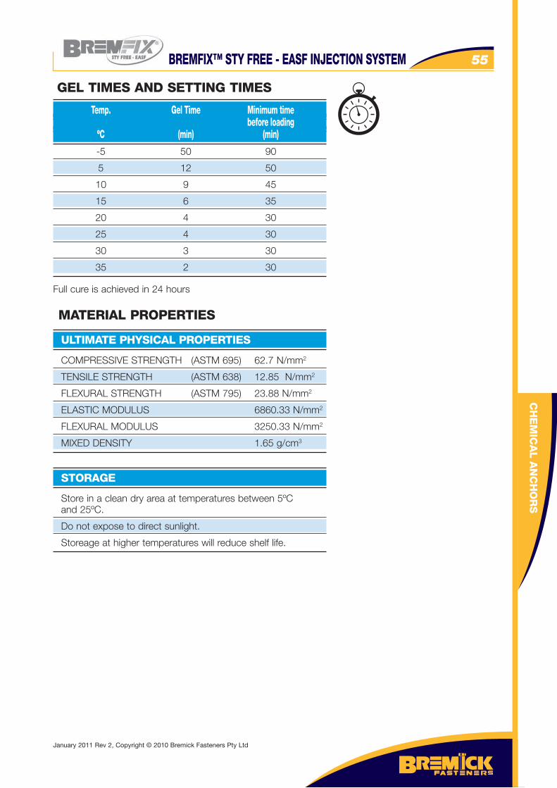
BREMFIX™ STY FREE - EASF INJECTION SYSTEM 55
COMPRESSIVE STRENGTH (ASTM 695) 62.7 N/mm2
TENSILE STRENGTH (ASTM 638) 12.85 N/mm2
FLEXURAL STRENGTH (ASTM 795) 23.88 N/mm2
ELASTIC MODULUS 6860.33 N/mm2
FLEXURAL MODULUS 3250.33 N/mm2
MIXED DENSITY 1.65 g/cm3
ULTIMATE PHYSICAL PROPERTIES
MATERIAL PROPERTIES
Store in a clean dry area at temperatures between 5ºC and 25ºC.
Do not expose to direct sunlight.
Storeage at higher temperatures will reduce shelf life.
STORAGE
CH
EM
ICA
L A
NC
HO
RS
-5 50 90
5 12 50
10 9 45
15 6 35
20 4 30
25 4 30
30 3 30
35 2 30
Full cure is achieved in 24 hours
Temp. Gel Time Minimum time before loading ºC (min) (min)
GEL TIMES AND SETTING TIMES
January 2011 Rev 2, Copyright © 2010 Bremick Fasteners Pty Ltd
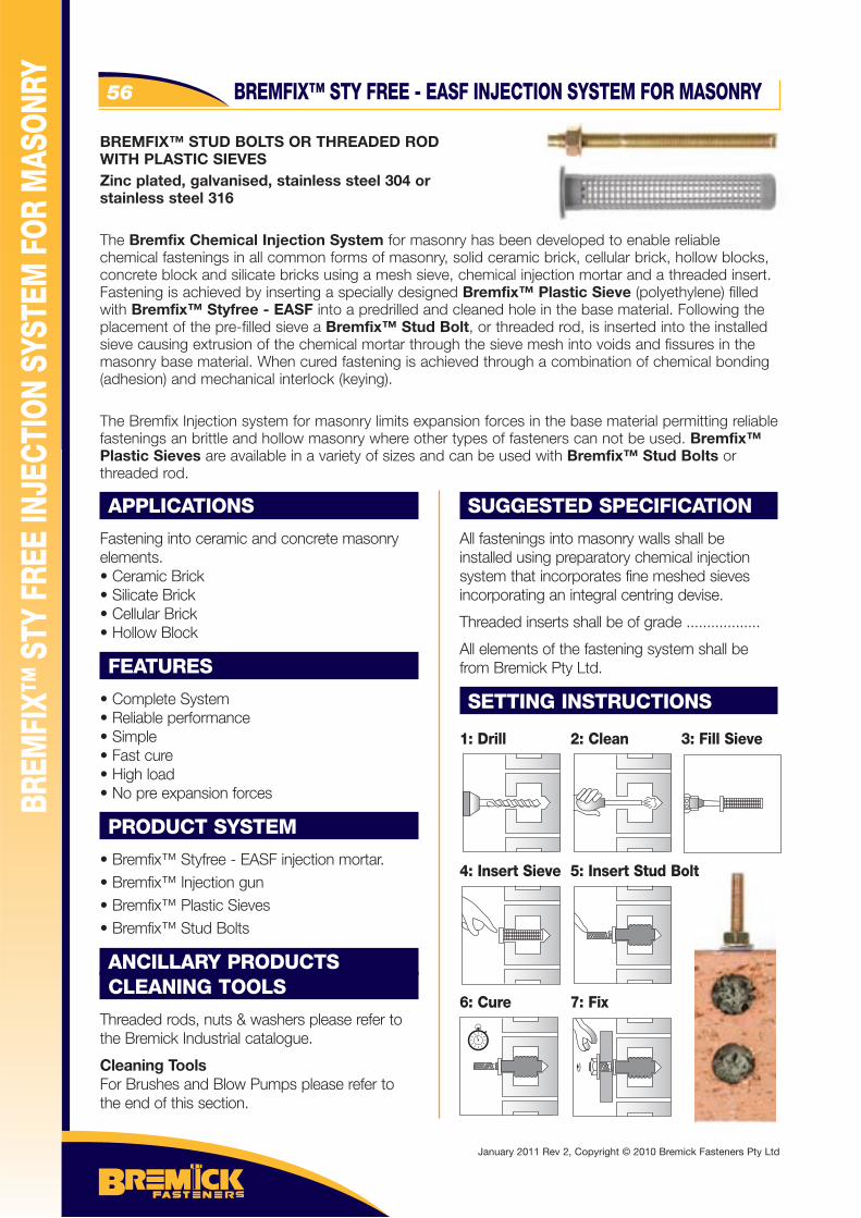
56
APPLICATIONS
Fastening into ceramic and concrete masonry elements.• Ceramic Brick• Silicate Brick• Cellular Brick• Hollow Block
FEATURES
• Complete System• Reliable performance• Simple• Fast cure• High load• No pre expansion forces
PRODUCT SYSTEM
• Bremfix™ Styfree - EASF injection mortar.• Bremfix™ Injection gun• Bremfix™ Plastic Sieves• Bremfix™ Stud Bolts
ANCILLARY PRODUCTSCLEANING TOOLS
Threaded rods, nuts & washers please refer to the Bremick Industrial catalogue.
Cleaning ToolsFor Brushes and Blow Pumps please refer to the end of this section.
SUGGESTED SPECIFICATION
All fastenings into masonry walls shall be installed using preparatory chemical injection system that incorporates fine meshed sieves incorporating an integral centring devise.
Threaded inserts shall be of grade ..................
All elements of the fastening system shall be from Bremick Pty Ltd.
SETTING INSTRUCTIONS
BREMFIX™ STUD BOLTS OR THREADED ROD WITH PLASTIC SIEVESZinc plated, galvanised, stainless steel 304 or stainless steel 316
The Bremfix Chemical Injection System for masonry has been developed to enable reliable chemical fastenings in all common forms of masonry, solid ceramic brick, cellular brick, hollow blocks, concrete block and silicate bricks using a mesh sieve, chemical injection mortar and a threaded insert. Fastening is achieved by inserting a specially designed Bremfix™ Plastic Sieve (polyethylene) filled with Bremfix™ Styfree - EASF into a predrilled and cleaned hole in the base material. Following the placement of the pre-filled sieve a Bremfix™ Stud Bolt, or threaded rod, is inserted into the installed sieve causing extrusion of the chemical mortar through the sieve mesh into voids and fissures in the masonry base material. When cured fastening is achieved through a combination of chemical bonding (adhesion) and mechanical interlock (keying).
The Bremfix Injection system for masonry limits expansion forces in the base material permitting reliable fastenings an brittle and hollow masonry where other types of fasteners can not be used. Bremfix™ Plastic Sieves are available in a variety of sizes and can be used with Bremfix™ Stud Bolts or threaded rod.
BREM
FIX™
STY
FRE
E IN
JECT
ION
SYST
EM F
OR M
ASON
RY
1: Drill 2: Clean 3: Fill Sieve
4: Insert Sieve 5: Insert Stud Bolt
6: Cure 7: Fix
BREMFIX™ STY FREE - EASF INJECTION SYSTEM FOR MASONRY
January 2011 Rev 2, Copyright © 2010 Bremick Fasteners Pty Ltd
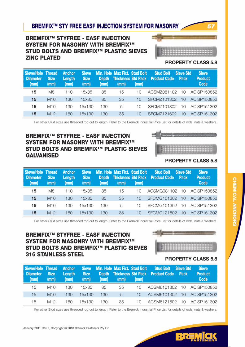
57
CH
EM
ICA
L A
NC
HO
RS
15 M8 110 15x85 85 15 10 ACSMZ081102 10 ACISP150852
15 M10 130 15x85 85 35 10 SFCMZ101302 10 ACISP150852
15 M10 130 15x130 130 5 10 SFCMZ101302 10 ACISP151302
15 M12 160 15x130 130 35 10 SFCMZ121602 10 ACISP151302
For other Stud sizes use threaded rod cut to length. Refer to the Bremick Industrial Price List for details of rods, nuts & washers.
Sieve/Hole Thread Anchor Sieve Min. Hole Max Fixt. Stud Bolt Stud Bolt Sieve Std Sieve Diameter Size Length Size Depth Thickness Std Pack Product Code Pack Product (mm) (mm) (mm) (mm) (mm) (mm) (mm) Code
BREMFIX™ STYFREE - EASF INJECTION SYSTEM FOR MASONRY WITH BREMFIX™ STUD BOLTS AND BREMFIX™ PLASTIC SIEVESZINC PLATED
15 M8 110 15x85 85 15 10 ACSMG081102 10 ACISP150852
15 M10 130 15x85 85 35 10 SFCMG101302 10 ACISP150852
15 M10 130 15x130 130 5 10 SFCMG101302 10 ACISP151302
15 M12 160 15x130 130 35 10 SFCMG121602 10 ACISP151302
For other Stud sizes use threaded rod cut to length. Refer to the Bremick Industrial Price List for details of rods, nuts & washers.
Sieve/Hole Thread Anchor Sieve Min. Hole Max Fixt. Stud Bolt Stud Bolt Sieve Std Sieve Diameter Size Length Size Depth Thickness Std Pack Product Code Pack Product (mm) (mm) (mm) (mm) (mm) (mm) (mm) Code
BREMFIX™ STYFREE - EASF INJECTION SYSTEM FOR MASONRY WITH BREMFIX™ STUD BOLTS AND BREMFIX™ PLASTIC SIEVESGALVANISED
15 M10 130 15x85 85 35 10 ACSM6101302 10 ACISP150852
15 M10 130 15x130 130 5 10 ACSM6101302 10 ACISP151302
15 M12 160 15x130 130 35 10 ACSM6121602 10 ACISP151302
For other Stud sizes use threaded rod cut to length. Refer to the Bremick Industrial Price List for details of rods, nuts & washers.
Sieve/Hole Thread Anchor Sieve Min. Hole Max Fixt. Stud Bolt Stud Bolt Sieve Std Sieve Diameter Size Length Size Depth Thickness Std Pack Product Code Pack Product (mm) (mm) (mm) (mm) (mm) (mm) (mm) Code
BREMFIX™ STYFREE - EASF INJECTION SYSTEM FOR MASONRY WITH BREMFIX™ STUD BOLTS AND BREMFIX™ PLASTIC SIEVES316 STAINLESS STEEL
BREMFIX™ STY FREE EASF INJECTION SYSTEM FOR MASONRY
PROPERTY CLASS 5.8
PROPERTY CLASS 5.8
PROPERTY CLASS 5.8
January 2011 Rev 2, Copyright © 2010 Bremick Fasteners Pty Ltd
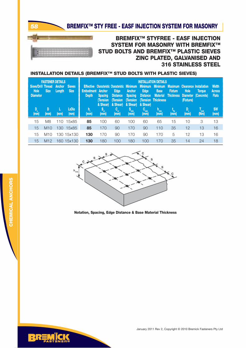
BREMFIX™ STY FREE - EASF INJECTION SYSTEM FOR MASONRY
BREMFIX™ STYFREE - EASF INJECTIONSYSTEM FOR MASONRY WITH BREMFIX™
STUD BOLTS AND BREMFIX™ PLASTIC SIEVESZINC PLATED, GALVANISED AND
316 STAINLESS STEEL
15 M8 110 15x85
15 M10 130 15x85
15 M10 130 15x130
15 M12 160 15x130
FASTENER DETAILS Sieve/Drill Thread Anchor Sieves Hole Size Length Size Diameter
Do D L LxDia (mm) (mm) (mm) (mm)
INSTALLATION DETAILS Effective Characteristic Characteristic Minimum Minimum Minimum Maximum Clearance Installation Width Embedment Anchor Edge Anchor Edge Base Fixture Hole Torque Across Depth Spacing Distance Spacing Distance Material Thickness Diameter (Concrete) Flats (Tension (Tension (Tension (Tension Thickness (Fixture) & Shear) & Shear) & Shear) & Shear) ht Scr Ccr Smin Cmin hmin tfi x Dc Tinst SW (mm) (mm) (mm) (mm) (mm) (mm) (mm) (mm) (Nm) (mm)
INSTALLATION DETAILS (BREMFIX™ STUD BOLTS WITH PLASTIC SIEVES)
85 100 60 100 60 65 15 10 3 13
85 170 90 170 90 110 35 12 13 16
130 170 90 170 90 170 5 12 13 16
130 180 100 180 100 170 35 14 24 18
Notation, Spacing, Edge Distance & Base Material Thickness
CH
EM
ICA
L A
NC
HO
RS
58
January 2011 Rev 2, Copyright © 2010 Bremick Fasteners Pty Ltd
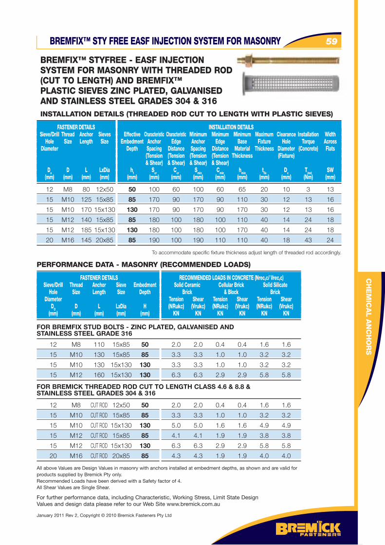
BREMFIX™ STY FREE EASF INJECTION SYSTEM FOR MASONRY 59
12 M8 80 12x50
15 M10 125 15x85
15 M10 170 15x130
15 M12 140 15x85
15 M12 185 15x130
20 M16 145 20x85
FASTENER DETAILS Sieve/Drill Thread Anchor Sieves Hole Size Length Size Diameter
Do D L LxDia (mm) (mm) (mm) (mm)
INSTALLATION DETAILS Effective Characteristic Characteristic Minimum Minimum Minimum Maximum Clearance Installation Width Embedment Anchor Edge Anchor Edge Base Fixture Hole Torque Across Depth Spacing Distance Spacing Distance Material Thickness Diameter (Concrete) Flats (Tension (Tension (Tension (Tension Thickness (Fixture) & Shear) & Shear) & Shear) & Shear) ht Scr Ccr Smin Cmin hmin tfi x Dc Tinst SW (mm) (mm) (mm) (mm) (mm) (mm) (mm) (mm) (Nm) (mm)
INSTALLATION DETAILS (THREADED ROD CUT TO LENGTH WITH PLASTIC SIEVES)
50 100 60 100 60 65 20 10 3 13
85 170 90 170 90 110 30 12 13 16
130 170 90 170 90 170 30 12 13 16
85 180 100 180 100 110 40 14 24 18
130 180 100 180 100 170 40 14 24 18
85 190 100 190 110 110 40 18 43 24
To accommodate specific fixture thickness adjust length of threaded rod accordingly.
12 M8 110 15x85 50
15 M10 130 15x85 85
15 M10 130 15x130 130
15 M12 160 15x130 130
FASTENER DETAILS Sieve/Drill Thread Anchor Sieve Embedment Hole Size Length Size Depth Diameter DO D L LxDia H (mm) (mm) (mm) (mm) (mm)
RECOMMENDED LOADS IN CONCRETE (Nrec,c/ Vrec,c) Solid Ceramic Cellular Brick Solid Silicate Brick & Block Brick Tension Shear Tension Shear Tension Shear (NRukc) (Vrukc) (NRukc) (Vrukc) (NRukc) (Vrukc) KN KN KN KN KN KN
2.0 2.0 0.4 0.4 1.6 1.6
3.3 3.3 1.0 1.0 3.2 3.2
3.3 3.3 1.0 1.0 3.2 3.2
6.3 6.3 2.9 2.9 5.8 5.8
All above Values are Design Values in masonry with anchors installed at embedment depths, as shown and are valid for products supplied by Bremick Pty only. Recommended Loads have been derived with a Safety factor of 4.All Shear Values are Single Shear.
PERFORMANCE DATA - MASONRY (RECOMMENDED LOADS)
FOR BREMFIX STUD BOLTS - ZINC PLATED, GALVANISED AND STAINLESS STEEL GRADE 316
12 M8 CUT ROD 12x50 50
15 M10 CUT ROD 15x85 85
15 M10 CUT ROD 15x130 130
15 M12 CUT ROD 15x85 85
15 M12 CUT ROD 15x130 130
20 M16 CUT ROD 20x85 85
2.0 2.0 0.4 0.4 1.6 1.6
3.3 3.3 1.0 1.0 3.2 3.2
5.0 5.0 1.6 1.6 4.9 4.9
4.1 4.1 1.9 1.9 3.8 3.8
6.3 6.3 2.9 2.9 5.8 5.8
4.3 4.3 1.9 1.9 4.0 4.0
FOR BREMICK THREADED ROD CUT TO LENGTH CLASS 4.6 & 8.8 & STAINLESS STEEL GRADES 304 & 316
For further performance data, including Characteristic, Working Stress, Limit State Design Values and design data please refer to our Web Site www.bremick.com.au
CH
EM
ICA
L A
NC
HO
RS
BREMFIX™ STYFREE - EASF INJECTION SYSTEM FOR MASONRY WITH THREADED ROD(CUT TO LENGTH) AND BREMFIX™ PLASTIC SIEVES ZINC PLATED, GALVANISED AND STAINLESS STEEL GRADES 304 & 316
January 2011 Rev 2, Copyright © 2010 Bremick Fasteners Pty Ltd
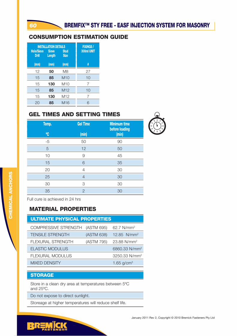
CH
EM
ICA
L A
NC
HO
RS
BREMFIX™ STY FREE - EASF INJECTION SYSTEM FOR MASONRY60
12 50 M8
15 85 M10
15 130 M10
15 85 M12
15 130 M12
20 85 M16
INSTALLATION DETAILS Hole/Sieve Sieve Stud Drill Length Size (mm) (mm) (mm)
FIXINGS / 300ml UNIT
#
27
10
7
10
7
6
-5 50 90
5 12 50
10 9 45
15 6 35
20 4 30
25 4 30
30 3 30
35 2 30
Full cure is achieved in 24 hrs
Temp. Gel Time Minimum time before loading ºC (min) (min)
GEL TIMES AND SETTING TIMES
CONSUMPTION ESTIMATION GUIDE
COMPRESSIVE STRENGTH (ASTM 695) 62.7 N/mm2
TENSILE STRENGTH (ASTM 638) 12.85 N/mm2
FLEXURAL STRENGTH (ASTM 795) 23.88 N/mm2
ELASTIC MODULUS 6860.33 N/mm2
FLEXURAL MODULUS 3250.33 N/mm2
MIXED DENSITY 1.65 g/cm3
ULTIMATE PHYSICAL PROPERTIES
MATERIAL PROPERTIES
Store in a clean dry area at temperatures between 5ºC and 25ºC.
Do not expose to direct sunlight.
Storeage at higher temperatures will reduce shelf life.
STORAGE
January 2011 Rev 2, Copyright © 2010 Bremick Fasteners Pty Ltd
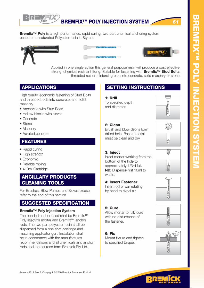
BR
EM
FIX
™ P
OLY
INJE
CT
ION
SY
ST
EM
BREMFIX™ POLY INJECTION SYSTEM 61
APPLICATIONS
High quality, economic fastening of Stud Bolts and threaded rods into concrete, and solid masonry.• Anchoring with Stud Bolts• Hollow blocks with sieves• Concrete• Stone• Masonry• Aerated concrete
FEATURES
• Rapid curing• High strength• Economic• Reliable mixing • 410ml Cartridge
ANCILLARY PRODUCTSCLEANING TOOLS
For Brushes, Blow Pumps and Sieves please refer to the end of this section
SUGGESTED SPECIFICATION
Bremfix™ Poly Injection SystemThe bonded anchor used shall be Bremfix™ Poly injection mortar and Bremfix™ anchor rods. The two part polyester resin shall be dispensed form a one shot cartridge and matching applicator gun. Installation shall be in accordance with the manufactures recommendations and all chemicals and anchor rods shall be sourced form Bremick Pty Ltd.
SETTING INSTRUCTIONS
1: DrillTo specified depthand diameter.
2: CleanBrush and blow debris form drilled hole. Base material must be clean and dry.
3: InjectInject mortar working from the bottom of the hole toapproximately 1/3rd full.NB: Dispense first 10ml towaste.
4: Insert FastenerInsert rod or bar rotatingby hand to expel air.
5: CureAllow mortar to fully cure with no disturbance of the fastener.
6: FixMount fixture and tightento specified torque.
Bremfix™ Poly is a high performance, rapid curing, two part chemical anchoring system based on unsaturated Polyester resin in Styrene.
Applied in one single action this general purpose resin will produce a cost effective, strong, chemical resistant fixing. Suitable for fastening with Bremfix™ Stud Bolts,
threaded rod or reinforcing bars into concrete, solid masonry or stone.
January 2011 Rev 2, Copyright © 2010 Bremick Fasteners Pty Ltd
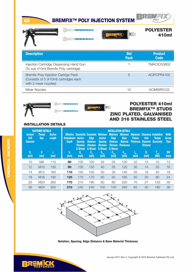
CH
EM
ICA
L A
NC
HO
RS
BREMFIX™ POLY INJECTION SYSTEM62
Injection Cartridge Dispensing Hand Gun 1 TMACICG3802 (To suit 410ml Bremfix Poly cartridge)
Bremfix Poly Injection Cartrige Pack 5 ACIPCPR4102 (Consists of 5 (410ml) cartridges each with 2 mixer nozzles)
Mixer Nozzles 10 ACIMIXR0102
Description Std Product Pack Code
POLYESTER 410ml
POLYESTER 410mlBREMFIX™ STUDS
ZINC PLATED, GALVANISEDAND 316 STAINLESS STEEL
10 M8 110
12 M10 130
14 M12 160
18 M16 190
25 M20 260
28 M24 300
FASTENER DETAILS Anchor/ Thread Anchor Drill Size Length Diameter
Do D L (mm) (mm) (mm)
INSTALLATION DETAILS Effective Characteristic Characteristic Minimum Minimum Minimum Maximum Clearance Installation Width Embedment Anchor Edge Anchor Edge Base Fixture Hole Torque Across Depth Spacing Distance Spacing Distance Material Thickness Diameter (Concrete) Flats (Tension (Tension (Tension (Tension Thickness (Fixture) & Shear) & Shear) & Shear) & Shear) ht Scr Ccr Smin Cmin hmin tfi x Dc Tinst SW (mm) (mm) (mm) (mm) (mm) (mm) (mm) (mm) (Nm) (mm)
INSTALLATION DETAILS
80 100 100 35 35 100 22 12 10 13
90 130 130 40 35 120 30 14 20 16
110 150 150 50 35 140 35 16 40 18
125 170 170 60 50 160 50 20 80 24
170 210 190 80 80 220 70 27 120 30
210 240 240 100 100 280 65 30 180 36
Notation, Spacing, Edge Distance & Base Material Thickness
January 2011 Rev 2, Copyright © 2010 Bremick Fasteners Pty Ltd
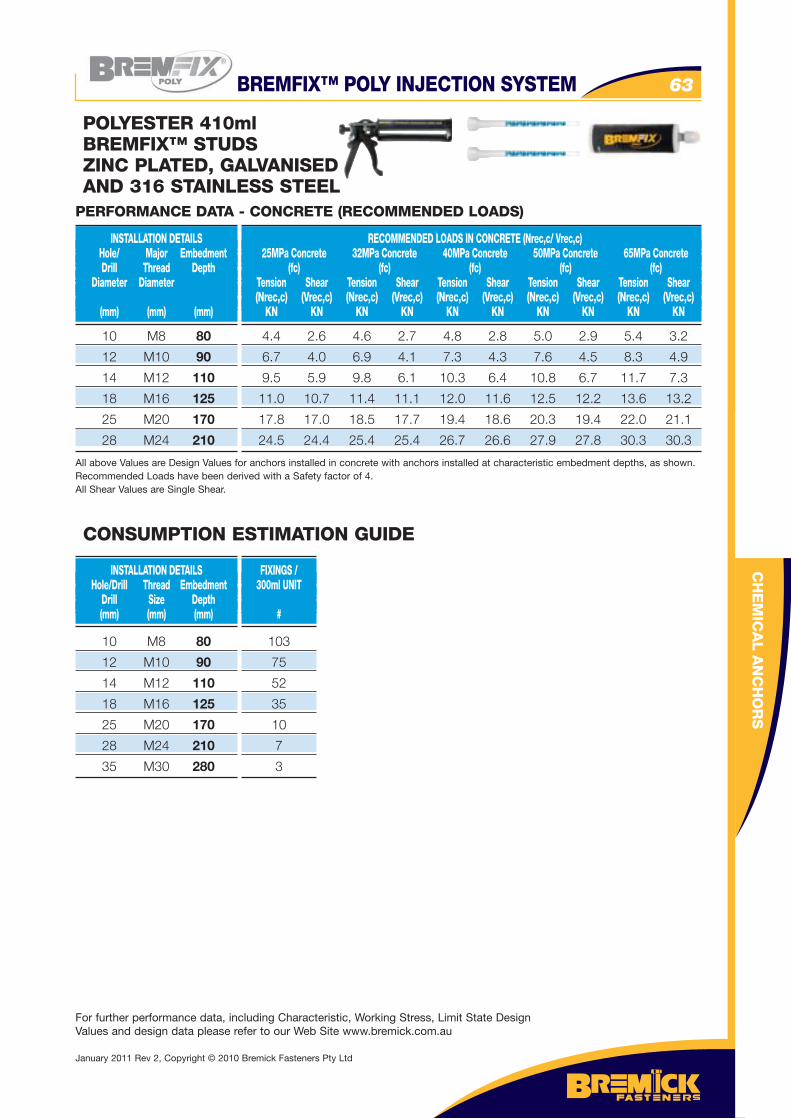
BREMFIX™ POLY INJECTION SYSTEM 63
CH
EM
ICA
L A
NC
HO
RS
POLYESTER 410mlBREMFIX™ STUDSZINC PLATED, GALVANISEDAND 316 STAINLESS STEEL
10 M8 80
12 M10 90
14 M12 110
18 M16 125
25 M20 170
28 M24 210
INSTALLATION DETAILS Hole/ Major Embedment Drill Thread Depth Diameter Diameter (mm) (mm) (mm)
RECOMMENDED LOADS IN CONCRETE (Nrec,c/ Vrec,c) 25MPa Concrete 32MPa Concrete 40MPa Concrete 50MPa Concrete 65MPa Concrete (fc) (fc) (fc) (fc) (fc) Tension Shear Tension Shear Tension Shear Tension Shear Tension Shear (Nrec,c) (Vrec,c) (Nrec,c) (Vrec,c) (Nrec,c) (Vrec,c) (Nrec,c) (Vrec,c) (Nrec,c) (Vrec,c) KN KN KN KN KN KN KN KN KN KN
4.4 2.6 4.6 2.7 4.8 2.8 5.0 2.9 5.4 3.2
6.7 4.0 6.9 4.1 7.3 4.3 7.6 4.5 8.3 4.9
9.5 5.9 9.8 6.1 10.3 6.4 10.8 6.7 11.7 7.3
11.0 10.7 11.4 11.1 12.0 11.6 12.5 12.2 13.6 13.2
17.8 17.0 18.5 17.7 19.4 18.6 20.3 19.4 22.0 21.1
24.5 24.4 25.4 25.4 26.7 26.6 27.9 27.8 30.3 30.3
All above Values are Design Values for anchors installed in concrete with anchors installed at characteristic embedment depths, as shown. Recommended Loads have been derived with a Safety factor of 4.All Shear Values are Single Shear.
PERFORMANCE DATA - CONCRETE (RECOMMENDED LOADS)
For further performance data, including Characteristic, Working Stress, Limit State Design Values and design data please refer to our Web Site www.bremick.com.au
10 M8 80
12 M10 90
14 M12 110
18 M16 125
25 M20 170
28 M24 210
35 M30 280
INSTALLATION DETAILS Hole/Drill Thread Embedment Drill Size Depth (mm) (mm) (mm)
FIXINGS / 300ml UNIT
#
103
75
52
35
10
7
3
CONSUMPTION ESTIMATION GUIDE
January 2011 Rev 2, Copyright © 2010 Bremick Fasteners Pty Ltd
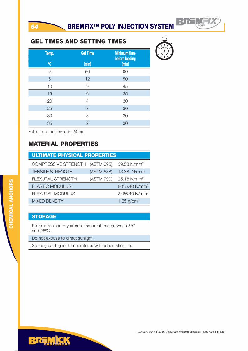
BREMFIX™ POLY INJECTION SYSTEM64
COMPRESSIVE STRENGTH (ASTM 695) 59.58 N/mm2
TENSILE STRENGTH (ASTM 638) 13.38 N/mm2
FLEXURAL STRENGTH (ASTM 790) 25.18 N/mm2
ELASTIC MODULUS 8015.40 N/mm2
FLEXURAL MODULUS 3486.40 N/mm2
MIXED DENSITY 1.65 g/cm3
ULTIMATE PHYSICAL PROPERTIES
MATERIAL PROPERTIES
Store in a clean dry area at temperatures between 5ºC and 25ºC.
Do not expose to direct sunlight.
Storeage at higher temperatures will reduce shelf life.
STORAGE
CH
EM
ICA
L A
NC
HO
RS
-5 50 90
5 12 50
10 9 45
15 6 35
20 4 30
25 3 30
30 3 30
35 2 30
Full cure is achieved in 24 hrs
Temp. Gel Time Minimum time before loading ºC (min) (min)
GEL TIMES AND SETTING TIMES
January 2011 Rev 2, Copyright © 2010 Bremick Fasteners Pty Ltd
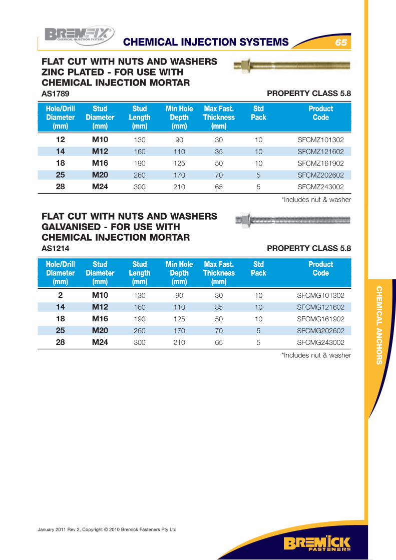
CH
EM
ICA
L A
NC
HO
RS
CHEMICAL INJECTION SYSTEMS 65
12 M10 130 90 30 10 SFCMZ101302
14 M12 160 110 35 10 SFCMZ121602
18 M16 190 125 50 10 SFCMZ161902
25 M20 260 170 70 5 SFCMZ202602
28 M24 300 210 65 5 SFCMZ243002
*Includes nut & washer
Hole/Drill Stud Stud Min Hole Max Fast. Std Product Diameter Diameter Length Depth Thickness Pack Code (mm) (mm) (mm) (mm) (mm)
FLAT CUT WITH NUTS AND WASHERSZINC PLATED - FOR USE WITH CHEMICAL INJECTION MORTARAS1789
2 M10 130 90 30 10 SFCMG101302
14 M12 160 110 35 10 SFCMG121602
18 M16 190 125 50 10 SFCMG161902
25 M20 260 170 70 5 SFCMG202602
28 M24 300 210 65 5 SFCMG243002
*Includes nut & washer
Hole/Drill Stud Stud Min Hole Max Fast. Std Product Diameter Diameter Length Depth Thickness Pack Code (mm) (mm) (mm) (mm) (mm)
FLAT CUT WITH NUTS AND WASHERSGALVANISED - FOR USE WITH CHEMICAL INJECTION MORTARAS1214
PROPERTY CLASS 5.8
PROPERTY CLASS 5.8
January 2011 Rev 2, Copyright © 2010 Bremick Fasteners Pty Ltd
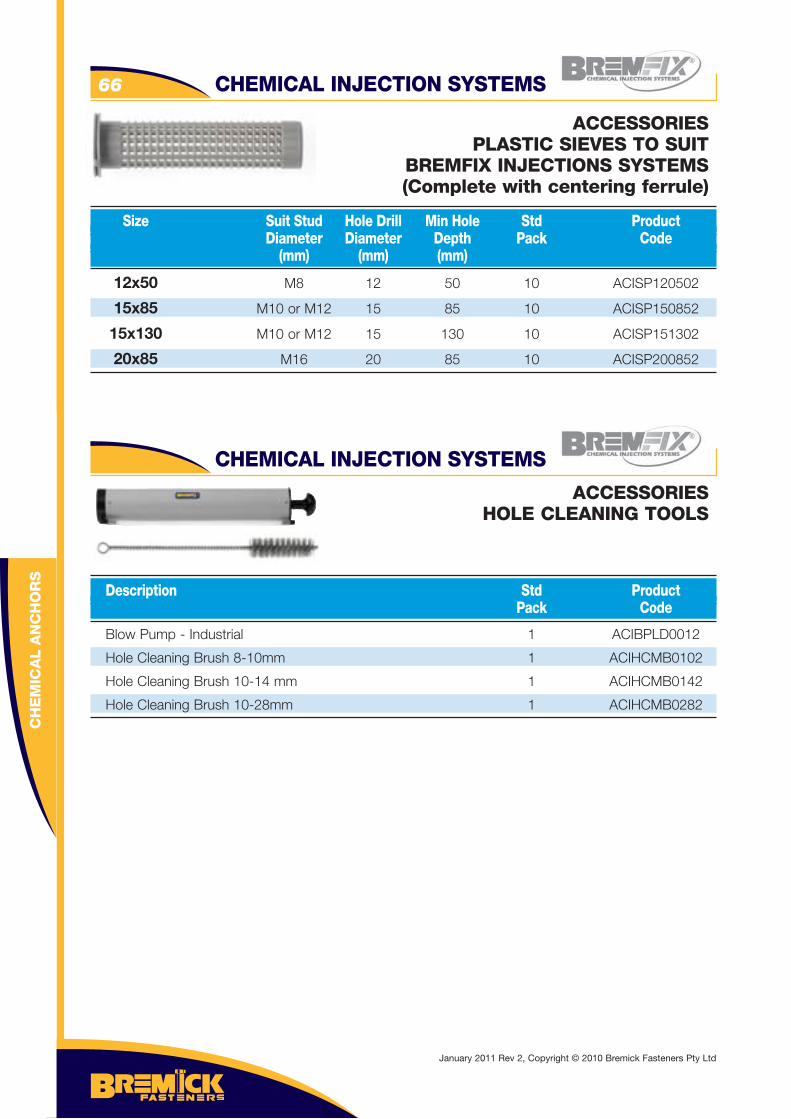
CHEMICAL INJECTION SYSTEMS66
Blow Pump - Industrial 1 ACIBPLD0012
Hole Cleaning Brush 8-10mm 1 ACIHCMB0102
Hole Cleaning Brush 10-14 mm 1 ACIHCMB0142
Hole Cleaning Brush 10-28mm 1 ACIHCMB0282
Description Std Product Pack Code
ACCESSORIESHOLE CLEANING TOOLS
12x50 M8 12 50 10 ACISP120502
15x85 M10 or M12 15 85 10 ACISP150852
15x130 M10 or M12 15 130 10 ACISP151302
20x85 M16 20 85 10 ACISP200852
Size Suit Stud Hole Drill Min Hole Std Product Diameter Diameter Depth Pack Code (mm) (mm) (mm)
ACCESSORIESPLASTIC SIEVES TO SUIT
BREMFIX INJECTIONS SYSTEMS(Complete with centering ferrule)
CH
EM
ICA
L A
NC
HO
RS
CHEMICAL INJECTION SYSTEMS
January 2011 Rev 2, Copyright © 2010 Bremick Fasteners Pty Ltd
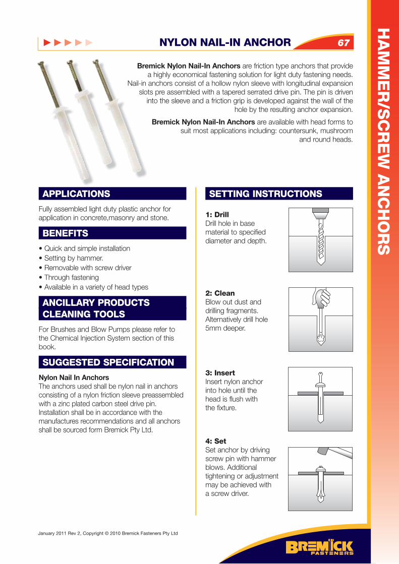
NYLON NAIL-IN ANCHOR 67
APPLICATIONS
Fully assembled light duty plastic anchor for application in concrete,masonry and stone.
BENEFITS
• Quick and simple installation • Setting by hammer.• Removable with screw driver • Through fastening• Available in a variety of head types
ANCILLARY PRODUCTSCLEANING TOOLS
For Brushes and Blow Pumps please refer to the Chemical Injection System section of this book.
SUGGESTED SPECIFICATION
Nylon Nail In AnchorsThe anchors used shall be nylon nail in anchors consisting of a nylon friction sleeve preassembled with a zinc plated carbon steel drive pin. Installation shall be in accordance with the manufactures recommendations and all anchors shall be sourced form Bremick Pty Ltd.
SETTING INSTRUCTIONS
1: DrillDrill hole in base material to specifieddiameter and depth.
2: CleanBlow out dust anddrilling fragments.Alternatively drill hole5mm deeper.
3: InsertInsert nylon anchorinto hole until the head is flush withthe fixture.
4: SetSet anchor by driving screw pin with hammer blows. Additional tightening or adjustment may be achieved with a screw driver.
Bremick Nylon Nail-In Anchors are friction type anchors that provide a highly economical fastening solution for light duty fastening needs.
Nail-in anchors consist of a hollow nylon sleeve with longitudinal expansion slots pre assembled with a tapered serrated drive pin. The pin is driven
into the sleeve and a friction grip is developed against the wall of the hole by the resulting anchor expansion.
Bremick Nylon Nail-In Anchors are available with head forms to suit most applications including: countersunk, mushroom
and round heads.
HA
MM
ER
/SC
RE
W A
NC
HO
RS
January 2011 Rev 2, Copyright © 2010 Bremick Fasteners Pty Ltd
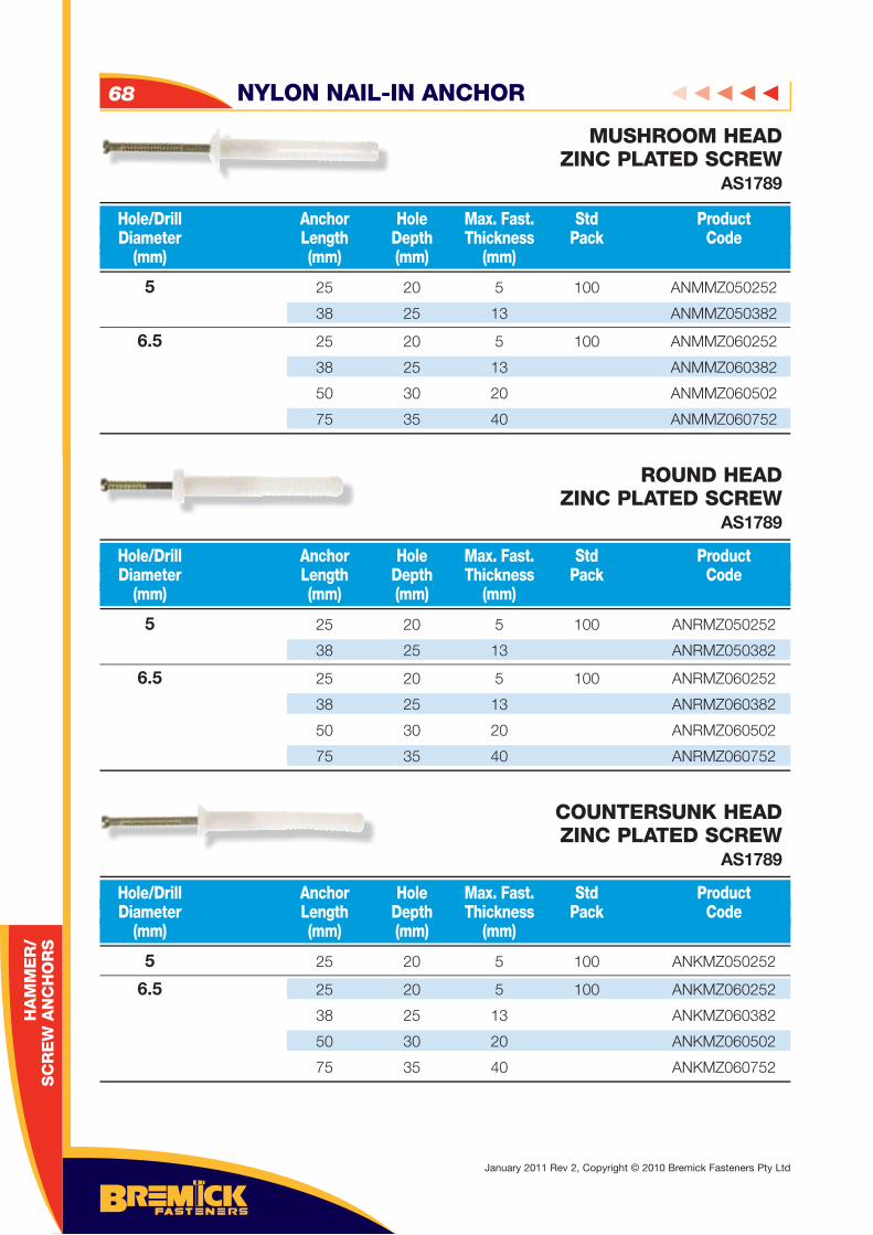
NYLON NAIL-IN ANCHOR68
HA
MM
ER
/ S
CR
EW
AN
CH
OR
S
5 25 20 5 100 ANMMZ050252
38 25 13 ANMMZ050382
6.5 25 20 5 100 ANMMZ060252
38 25 13 ANMMZ060382
50 30 20 ANMMZ060502
75 35 40 ANMMZ060752
Hole/Drill Anchor Hole Max. Fast. Std Product Diameter Length Depth Thickness Pack Code (mm) (mm) (mm) (mm)
MUSHROOM HEADZINC PLATED SCREW
AS1789
5 25 20 5 100 ANRMZ050252
38 25 13 ANRMZ050382
6.5 25 20 5 100 ANRMZ060252
38 25 13 ANRMZ060382
50 30 20 ANRMZ060502
75 35 40 ANRMZ060752
Hole/Drill Anchor Hole Max. Fast. Std Product Diameter Length Depth Thickness Pack Code (mm) (mm) (mm) (mm)
ROUND HEADZINC PLATED SCREW
AS1789
5 25 20 5 100 ANKMZ050252
6.5 25 20 5 100 ANKMZ060252
38 25 13 ANKMZ060382
50 30 20 ANKMZ060502
75 35 40 ANKMZ060752
Hole/Drill Anchor Hole Max. Fast. Std Product Diameter Length Depth Thickness Pack Code (mm) (mm) (mm) (mm)
COUNTERSUNK HEADZINC PLATED SCREW
AS1789
January 2011 Rev 2, Copyright © 2010 Bremick Fasteners Pty Ltd
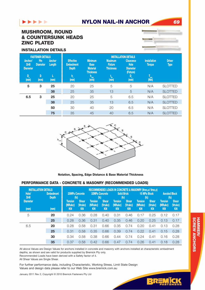
NYLON NAIL-IN ANCHOR 69
HA
MM
ER
/S
CR
EW
AN
CH
OR
S
MUSHROOM, ROUND& COUNTERSUNK HEADSZINC PLATED
5 3 25
38
6.5 3 25
38
50
75
FASTENER DETAILS Anchor/ Pin Anchor Drill Diameter Length Diameter
Do D L (mm) (mm) (mm)
INSTALLATION DETAILS Effective Minimum Maximum Clearance Installation Driver Embedment Base Fixture Hole Torque Type Depth Material Thickness Diameter Thickness (Fixture) ht hmin tfi x Dc Tinst (mm) (mm) (mm) (mm) (Nm)
INSTALLATION DETAILS
20 25 5 5 N/A SLOTTED
25 35 13 5 N/A SLOTTED
20 25 5 6.5 N/A SLOTTED
25 35 13 6.5 N/A SLOTTED
30 40 20 6.5 N/A SLOTTED
35 45 40 6.5 N/A SLOTTED
Notation, Spacing, Edge Distance & Base Material Thickness
5 20
25
6.5 20
25
30
35
INSTALLATION DETAILS Hole/ Embedment Drill Depth Diameter (mm) (mm)
RECOMMENDED LOADS IN CONCRETE & MASONRY (Nrec,c/ Vrec,c) 25MPa Concrete 32MPa Concrete Solid Brick 15 MPa Block Aerated Block (fc) (fc) (fc) (fc) (fc) Tension Shear Tension Shear Tension Shear Tension Shear Tension Shear (NRukc) (Vrukc) (NRukc) (Vrukc) (NRukc) (Vrukc) (NRukc) (Vrukc) (NRukc) (Vrukc) KN KN KN KN KN KN KN KN KN KN
PERFORMANCE DATA - CONCRETE & MASONRY (RECOMMENDED LOADS)
0.24 0.36 0.28 0.40 0.31 0.46 0.17 0.25 0.12 0.17
0.28 0.36 0.31 0.40 0.35 0.46 0.20 0.25 0.13 0.17
0.28 0.58 0.31 0.66 0.35 0.74 0.20 0.41 0.13 0.28
0.31 0.58 0.35 0.66 0.39 0.74 0.22 0.41 0.15 0.28
0.34 0.58 0.38 0.66 0.44 0.74 0.24 0.41 0.16 0.28
0.37 0.58 0.42 0.66 0.47 0.74 0.26 0.41 0.18 0.28
All above Values are Design Values for anchors installed in concrete and masonry with anchors installed at characteristic embedment depths, as shown and are valid for products supplied by Bremick Pty only.Recommended Loads have been derived with a Safety factor of 4.All Shear Values are Single Shear.
For further performance data, including Characteristic, Working Stress, Limit State Design Values and design data please refer to our Web Site www.bremick.com.au
January 2011 Rev 2, Copyright © 2010 Bremick Fasteners Pty Ltd
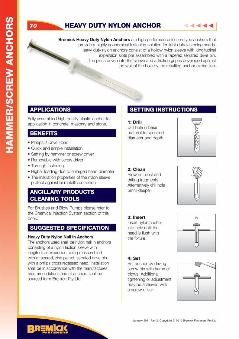
Bremick Heavy Duty Nylon Anchors are high performance friction type anchors that provide a highly economical fastening solution for light duty fastening needs. Heavy duty nylon anchors consist of a hollow nylon sleeve with longitudinal
expansion slots pre assembled with a tapered serrated drive pin. The pin is driven into the sleeve and a friction grip is developed against
the wall of the hole by the resulting anchor expansion.
APPLICATIONS
Fully assembled high quality plastic anchor for application in concrete, masonry and stone.
BENEFITS
• Phillips 2 Drive Head• Quick and simple installation • Setting by hammer or screw driver• Removable with screw driver • Through fastening• Higher loading due to enlarged head diameter • The insulation properties of the nylon sleeve protect against bi-metallic corrosion
ANCILLARY PRODUCTSCLEANING TOOLS
For Brushes and Blow Pumps please refer to the Chemical Injection System section of this book.
SUGGESTED SPECIFICATION
Heavy Duty Nylon Nail In AnchorsThe anchors used shall be nylon nail in anchors consisting of a nylon friction sleeve with longitudinal expansion slots preassembled with a tapered, zinc plated, serrated drive pin with a philips cross recessed head. Installation shall be in accordance with the manufactures recommendations and all anchors shall be sourced form Bremick Pty Ltd.
SETTING INSTRUCTIONS
1: DrillDrill hole in base material to specifieddiameter and depth.
2: CleanBlow out dust anddrilling fragments.Alternatively drill hole5mm deeper.
3: InsertInsert nylon anchorinto hole until the head is flush withthe fixture.
4: SetSet anchor by driving screw pin with hammer blows. Additional tightening or adjustment may be achieved with a screw driver.
Bremick Heavy Duty Nylon Anchors are highprovide a highly economical fasteningHeavy duty nylon anchors consist o
expansion slots pre assemThe pin is driven into the sleeve
the wall of the
HEAVY DUTY NYLON ANCHOR70
HA
MM
ER
/SC
RE
W A
NC
HO
RS
January 2011 Rev 2, Copyright © 2010 Bremick Fasteners Pty Ltd
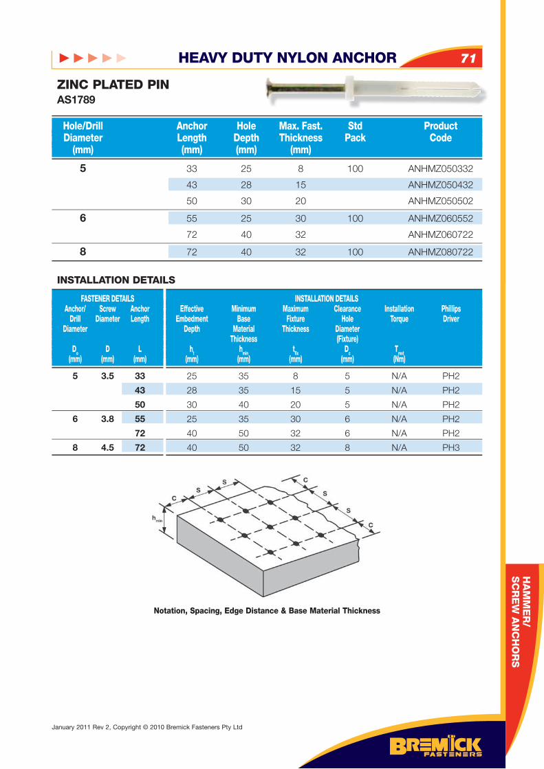
HEAVY DUTY NYLON ANCHOR 71
HA
MM
ER
/SC
RE
W A
NC
HO
RS
HA
MM
ER
/S
CR
EW
AN
CH
OR
S
5 33 25 8 100 ANHMZ050332
43 28 15 ANHMZ050432
50 30 20 ANHMZ050502
6 55 25 30 100 ANHMZ060552
72 40 32 ANHMZ060722
8 72 40 32 100 ANHMZ080722
Hole/Drill Anchor Hole Max. Fast. Std Product Diameter Length Depth Thickness Pack Code (mm) (mm) (mm) (mm)
ZINC PLATED PINAS1789
5 3.5 33
43
50
6 3.8 55
72
8 4.5 72
FASTENER DETAILS Anchor/ Screw Anchor Drill Diameter Length Diameter
Do D L (mm) (mm) (mm)
INSTALLATION DETAILS Effective Minimum Maximum Clearance Installation Phillips Embedment Base Fixture Hole Torque Driver Depth Material Thickness Diameter Thickness (Fixture) ht hmin tfi x Dc Tmst (mm) (mm) (mm) (mm) (Nm)
INSTALLATION DETAILS
25 35 8 5 N/A PH2
28 35 15 5 N/A PH2
30 40 20 5 N/A PH2
25 35 30 6 N/A PH2
40 50 32 6 N/A PH2
40 50 32 8 N/A PH3
Notation, Spacing, Edge Distance & Base Material Thickness
January 2011 Rev 2, Copyright © 2010 Bremick Fasteners Pty Ltd
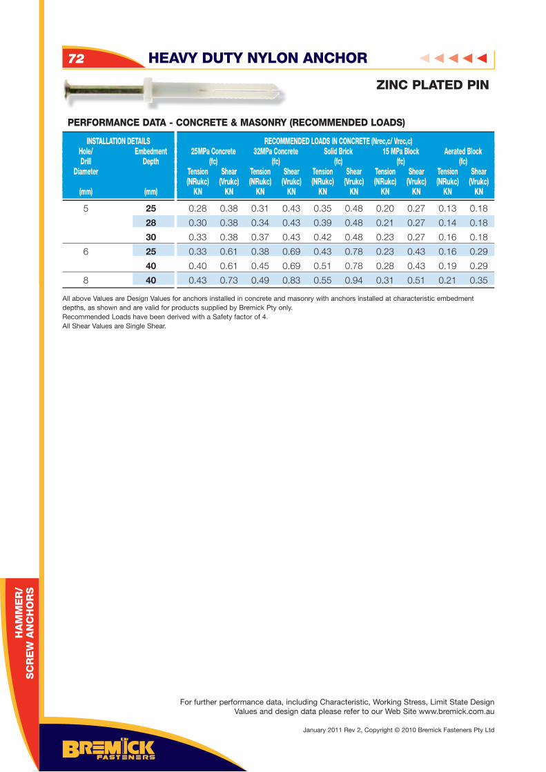
HEAVY DUTY NYLON ANCHOR72
HA
MM
ER
/ S
CR
EW
AN
CH
OR
S
5 25
28
30
6 25
40
8 40
INSTALLATION DETAILS Hole/ Embedment Drill Depth Diameter (mm) (mm)
RECOMMENDED LOADS IN CONCRETE (Nrec,c/ Vrec,c) 25MPa Concrete 32MPa Concrete Solid Brick 15 MPa Block Aerated Block (fc) (fc) (fc) (fc) (fc) Tension Shear Tension Shear Tension Shear Tension Shear Tension Shear (NRukc) (Vrukc) (NRukc) (Vrukc) (NRukc) (Vrukc) (NRukc) (Vrukc) (NRukc) (Vrukc) KN KN KN KN KN KN KN KN KN KN
PERFORMANCE DATA - CONCRETE & MASONRY (RECOMMENDED LOADS)
0.28 0.38 0.31 0.43 0.35 0.48 0.20 0.27 0.13 0.18
0.30 0.38 0.34 0.43 0.39 0.48 0.21 0.27 0.14 0.18
0.33 0.38 0.37 0.43 0.42 0.48 0.23 0.27 0.16 0.18
0.33 0.61 0.38 0.69 0.43 0.78 0.23 0.43 0.16 0.29
0.40 0.61 0.45 0.69 0.51 0.78 0.28 0.43 0.19 0.29
0.43 0.73 0.49 0.83 0.55 0.94 0.31 0.51 0.21 0.35
All above Values are Design Values for anchors installed in concrete and masonry with anchors installed at characteristic embedment depths, as shown and are valid for products supplied by Bremick Pty only.Recommended Loads have been derived with a Safety factor of 4.All Shear Values are Single Shear.
ZINC PLATED PIN
For further performance data, including Characteristic, Working Stress, Limit State Design Values and design data please refer to our Web Site www.bremick.com.au
January 2011 Rev 2, Copyright © 2010 Bremick Fasteners Pty Ltd
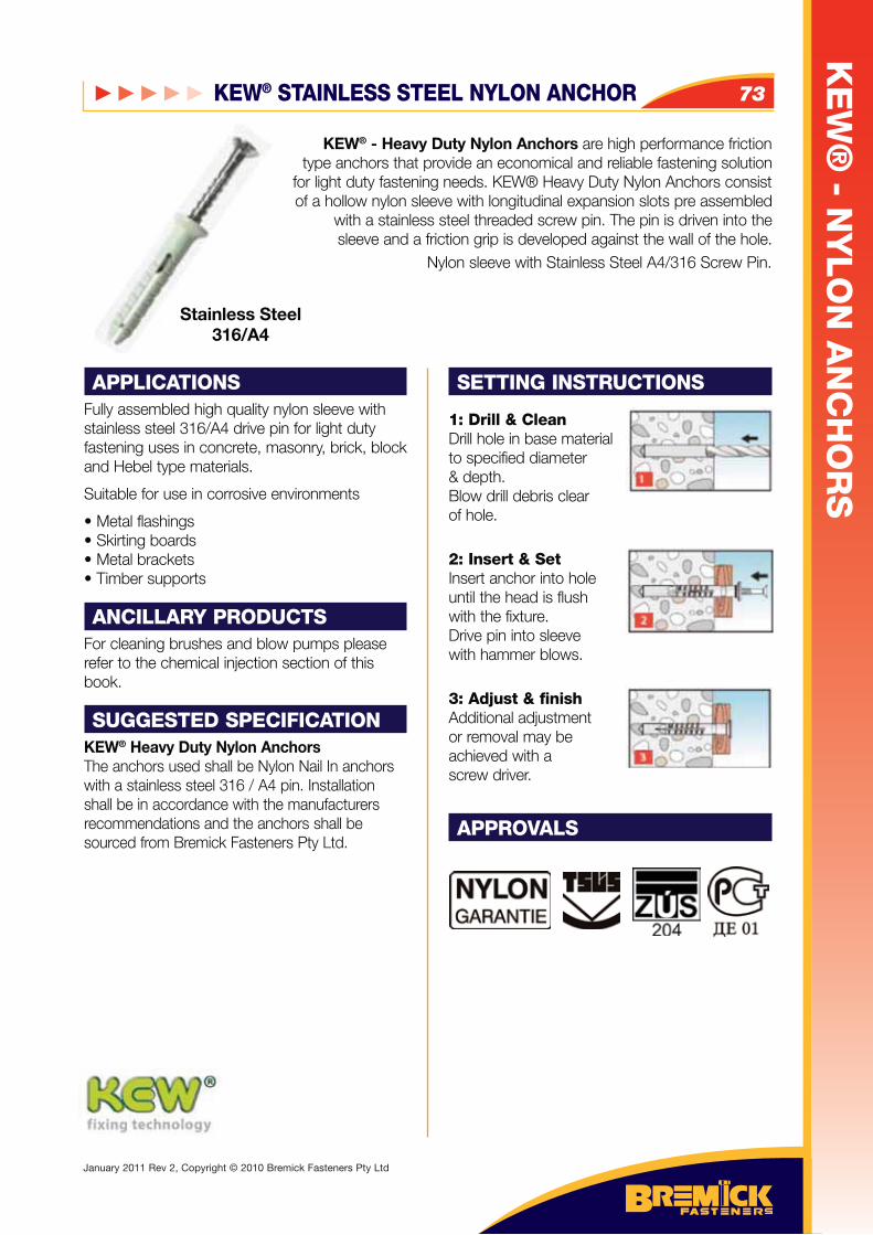
APPLICATIONSFully assembled high quality nylon sleeve with stainless steel 316/A4 drive pin for light duty fastening uses in concrete, masonry, brick, block and Hebel type materials.
Suitable for use in corrosive environments
Metal flashings Skirting boards Metal brackets Timber supports
ANCILLARY PRODUCTSFor cleaning brushes and blow pumps please refer to the chemical injection section of this book.
SUGGESTED SPECIFICATIONKEW® Heavy Duty Nylon Anchors The anchors used shall be Nylon Nail In anchors with a stainless steel 316 / A4 pin. Installation shall be in accordance with the manufacturers recommendations and the anchors shall be sourced from Bremick Fasteners Pty Ltd.
SETTING INSTRUCTIONS
1: Drill & CleanDrill hole in base material to specified diameter & depth.Blow drill debris clear of hole.
2: Insert & SetInsert anchor into hole until the head is flush with the fixture. Drive pin into sleeve with hammer blows.
3: Adjust & finishAdditional adjustment or removal may be achieved with a screw driver.
APPROVALS
KEW® - Heavy Duty Nylon Anchors are high performance friction type anchors that provide an economical and reliable fastening solution
for light duty fastening needs. KEW® Heavy Duty Nylon Anchors consist of a hollow nylon sleeve with longitudinal expansion slots pre assembled
with a stainless steel threaded screw pin. The pin is driven into the sleeve and a friction grip is developed against the wall of the hole.
Nylon sleeve with Stainless Steel A4/316 Screw Pin.
Stainless Steel316/A4
KEW® STAINLESS STEEL NYLON ANCHOR 73
KE
W®
- NY
LO
N A
NC
HO
RS
January 2011 Rev 2, Copyright © 2010 Bremick Fasteners Pty Ltd
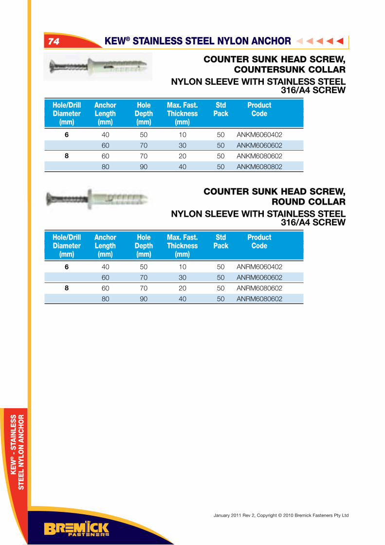
COUNTER SUNK HEAD SCREW, COUNTERSUNK COLLAR
NYLON SLEEVE WITH STAINLESS STEEL 316/A4 SCREW
COUNTER SUNK HEAD SCREW, ROUND COLLAR
NYLON SLEEVE WITH STAINLESS STEEL 316/A4 SCREW
6
8
6
8
Hole/Drill Anchor Hole Max. Fast. Std Product Diameter Length Depth Thickness Pack Code (mm) (mm) (mm) (mm)
Hole/Drill Anchor Hole Max. Fast. Std Product Diameter Length Depth Thickness Pack Code (mm) (mm) (mm) (mm)
40
60
60
80
50
70
70
90
10
30
20
40
50
50
50
50
ANKM6060402
ANKM6060602
ANKM6080602
ANKM6080802
40
60
60
80
50
70
70
90
10
30
20
40
50
50
50
50
ANRM6060402
ANRM6060602
ANRM6080602
ANRM6080602
KEW® STAINLESS STEEL NYLON ANCHOR74
KE
W® -
STA
INLE
SS
STE
EL
NYL
ON
AN
CH
OR
January 2011 Rev 2, Copyright © 2010 Bremick Fasteners Pty Ltd
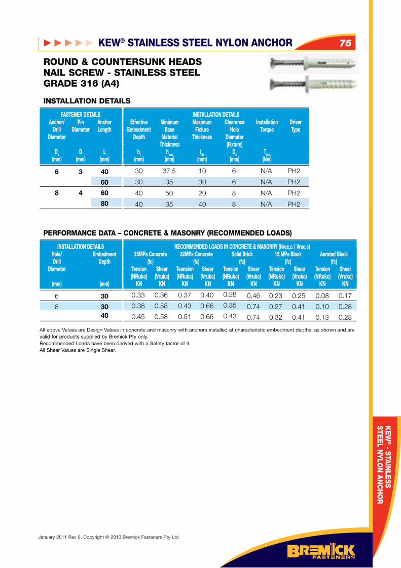
6 3 40
60
8 4 60
80
FASTENER DETAILS Anchor/ Pin Anchor Drill Diameter Length Diameter
Do D L (mm) (mm) (mm)
INSTALLATION DETAILS Effective Minimum Maximum Clearance Installation Driver Embedment Base Fixture Hole Torque Type Depth Material Thickness Diameter Thickness (Fixture) ht hmin tfix Dc Tinst (mm) (mm) (mm) (mm) (Nm)
INSTALLATION DETAILS
ROUND & COUNTERSUNK HEADSNAIL SCREW - STAINLESS STEEL GRADE 316 (A4)
6 30
8 30 40
INSTALLATION DETAILS Hole/ Embedment Drill Depth Diameter (mm) (mm)
RECOMMENDED LOADS IN CONCRETE & MASONRY (Nrec,c / Vrec,c) 25MPa Concrete 32MPa Concrete Solid Brick 15 MPa Block Aerated Block (fc) (fc) (fc) (fc) (fc) Tension Shear Teansion Shear Tension Shear Tension Shear Tension Shear (NRukc) (Vrukc) (NRukc) (Vrukc) (NRukc) (Vrukc) (NRukc) (Vrukc) (NRukc) (Vrukc) KN KN KN KN KN KN KN KN KN KN
All above Values are Design Values in concrete and masonry with anchors installed at characteristic embedment depths, as shown and are valid for products supplied by Bremick Pty only. Recommended Loads have been derived with a Safety factor of 4.All Shear Values are Single Shear.
PERFORMANCE DATA – CONCRETE & MASONRY (RECOMMENDED LOADS)
30
30
40
40
37.5
35
50
35
10
30
20
40
6
6
8
8
N/A
N/A
N/A
N/A
PH2
PH2
PH2
PH2
0.33
0.38
0.45
0.36
0.58
0.58
0.37
0.43
0.51
0.40
0.66
0.66
0.28
0.35
0.43
0.46
0.74
0.74
0.23
0.27
0.32
0.25
0.41
0.41
0.08
0.10
0.13
0.17
0.28
0.28
KEW® STAINLESS STEEL NYLON ANCHOR 75
KE
W® - STA
INLE
SS
STEE
L NYLO
N A
NC
HO
R
January 2011 Rev 2, Copyright © 2010 Bremick Fasteners Pty Ltd
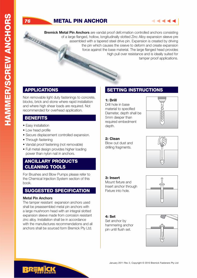
Bremick Metal Pin Anchors are vandal proof deformation controlled anchors consisting of a large flanged, hollow, longitudinally slotted Zinc Alloy expansion sleeve pre
assembled with a tapered steel drive pin. Expansion is created by driving the pin which causes the sleeve to deform and create expansion force against the base material. The large flanged head provides
high pull over resistance and is ideally suited for tamper proof applications.
APPLICATIONS
Non removable light duty fastenings to concrete, blocks, brick and stone where rapid installation and where high shear loads are required. Not recommended for overhead application.
BENEFITS
• Easy installation• Low head profile• Secure displacement controlled expansion.• Through fastening• Vandal proof fastening (not removable)• Full metal design provides higher loading power than nylon nail in anchors.
ANCILLARY PRODUCTSCLEANING TOOLS
For Brushes and Blow Pumps please refer to the Chemical Injection System section of this book.
SUGGESTED SPECIFICATION
Metal Pin AnchorsThe tamper resistant expansion anchors used shall be preassembled metal pin anchors with a large mushroom head with an integral slotted expansion sleeve made from corrosion resistant zinc alloy. Installation shall be in accordance with the manufactures recommendations and all anchors shall be sourced form Bremick Pty Ltd.
SETTING INSTRUCTIONS
1: DrillDrill hole in base material to specifiedDiameter, depth shall be5mm deeper thanrequired embedment depth.
2: CleanBlow out dust anddrilling fragments.
3: InsertMount fixture andInsert anchor throughFixture into hole.
4: SetSet anchor byhammering anchorpin until flush set.
Bremick Metal Pin Anchors are vandal proof defoof a large flanged, hollow, longitudinally s
assembled with a tapered steel drivthe pin which causes the slforce against the base mat
high pull o
METAL PIN ANCHOR76
HA
MM
ER
/SC
RE
W A
NC
HO
RS
January 2011 Rev 2, Copyright © 2010 Bremick Fasteners Pty Ltd
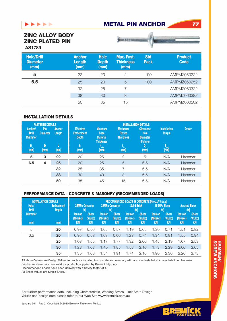
HA
MM
ER
/S
CR
EW
AN
CH
OR
S
METAL PIN ANCHOR 77
For further performance data, including Characteristic, Working Stress, Limit State Design Values and design data please refer to our Web Site www.bremick.com.au
January 2011 Rev 2, Copyright © 2010 Bremick Fasteners Pty Ltd
5 22 20 2 100 AMPMZ050222
6.5 25 20 5 100 AMPMZ060252
32 25 7 AMPMZ060322
38 30 8 AMPMZ060382
50 35 15 AMPMZ060502
Hole/Drill Anchor Hole Max. Fast. Std Product Diameter Length Depth Thickness Pack Code (mm) (mm) (mm) (mm)
ZINC ALLOY BODYZINC PLATED PIN AS1789
5 3 22
6.5 4 25
32
38
50
FASTENER DETAILS Anchor/ Pin Anchor Drill Diameter Length Diameter
Do D L (mm) (mm) (mm)
INSTALLATION DETAILS Effective Minimum Maximum Clearance Installation Driver Embedment Base Fixture Hole Torque Depth Material Thickness Diameter Thickness (Fixture) ht hmin tfi x Dc Tinst (mm) (mm) (mm) (mm) (Nm)
INSTALLATION DETAILS
20 25 2 5 N/A Hammer
20 25 5 6.5 N/A Hammer
25 35 7 6.5 N/A Hammer
30 40 8 6.5 N/A Hammer
35 45 15 6.5 N/A Hammer
5 20
6.5 20
25
30
35
INSTALLATION DETAILS Hole/ Embedment Drill Depth Diameter (mm) (mm)
RECOMMENDED LOADS IN CONCRETE (Nrec,c/ Vrec,c) 25MPa Concrete 32MPa Concrete Solid Brick 15 MPa Block Aerated Block (fc) (fc) (fc) (fc) (fc) Tension Shear Tension Shear Tension Shear Tension Shear Tension Shear (NRukc) (Vrukc) (NRukc) (Vrukc) (NRukc) (Vrukc) (NRukc) (Vrukc) (NRukc) (Vrukc) KN KN KN KN KN KN KN KN KN KN
PERFORMANCE DATA - CONCRETE & MASONRY (RECOMMENDED LOADS)
0.93 0.50 1.05 0.57 1.19 0.65 1.30 0.71 1.51 0.82
0.95 0.58 1.08 0.66 1.23 0.74 1.34 0.81 1.55 0.94
1.03 1.55 1.17 1.77 1.32 2.00 1.45 2.19 1.67 2.53
1.23 1.63 1.40 1.85 1.58 2.10 1.73 2.29 2.00 2.65
1.35 1.68 1.54 1.91 1.74 2.16 1.90 2.36 2.20 2.73
All above Values are Design Values for anchors installed in concrete and masonry with anchors installed at characteristic embedment depths, as shown and are valid for products supplied by Bremick Pty only.Recommended Loads have been derived with a Safety factor of 4.All Shear Values are Single Shear.
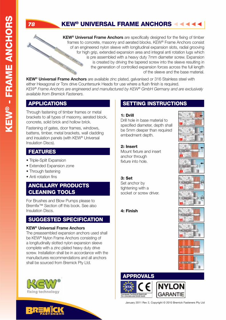
APPLICATIONS
Through fastening of timber frames or metal brackets to all types of masonry, aerated block, concrete, solid brick and hollow brick.Fastening of gates, door frames, windows, battens, timber, metal brackets, wall cladding and insulation panels (with KEW® Universal Insulation Discs).
FEATURES
• Triple-Split Expansion• Extended Expansion zone• Through fastening• Anti rotation fins
ANCILLARY PRODUCTSCLEANING TOOLS
For Brushes and Blow Pumps please to Bremfix™ Section off this book. See also Insulation Discs.
SUGGESTED SPECIFICATION
KEW® Universal Frame AnchorsThe preassembled expansion anchors used shall be KEW® Nylon Frame Anchors consisting of a longitudinally slotted nylon expansion sleeve complete with a zinc plated heavy duty drive screw. Installation shall be in accordance with the manufactures recommendations and all anchors shall be sourced from Bremick Pty Ltd.
SETTING INSTRUCTIONS
1: DrillDrill hole in base material to specified diameter, depth shall be 5mm deeper than required embedment depth.
2: InsertMount fixture and insert anchor throughfixture into hole.
3: SetSet anchor by tightening with a socket or screw driver.
4: Finish
APPROVALS
KEW® Universal Frame Anchors are specifically designed for the fixing of timber frames to concrete, masonry and aerated blocks. KEW® Frame Anchors consist
of an engineered nylon sleeve with longitudinal expansion slots, radial grooving for high grip, extended expansion area and integral anti rotation lugs which
is pre assembled with a heavy duty 7mm diameter screw. Expansion is created by driving the tapered screw into the sleeve resulting in
the generation of controlled expansion forces across the full length of the sleeve and the base material.
KEW® Universal Frame Anchors are available zinc plated, galvanised or 316 Stainless steel with either Hexagonal or Torx drive Countersunk Heads for use where a flush finish is required. KEW® Frame Anchors are engineered and manufactured by KEW® GmbH Germany and are exclusively available from Bremick Fasteners.
KEW® UNIVERSAL FRAME ANCHORS78
KE
W® -
FR
AM
E A
NC
HO
RS
January 2011 Rev 2, Copyright © 2010 Bremick Fasteners Pty Ltd
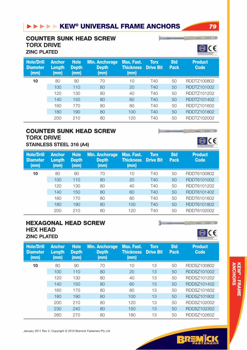
KEW® UNIVERSAL FRAME ANCHORS 79
January 2011 Rev 2, Copyright © 2010 Bremick Fasteners Pty Ltd
10 80 90 70 10 T40 50 RDDTZ100802 100 110 80 20 T40 50 RDDTZ101002 120 130 80 40 T40 50 RDDTZ101202 140 150 80 60 T40 50 RDDTZ101402 160 170 80 80 T40 50 RDDTZ101602 180 190 80 100 T40 50 RDDTZ101802 200 210 80 120 T40 50 RDDTZ102002
10 80 90 70 10 T40 50 RDDT6100802 100 110 80 20 T40 50 RDDT6101002 120 130 80 40 T40 50 RDDT6101202 140 150 80 60 T40 50 RDDT6101402 160 170 80 80 T40 50 RDDT6101602 180 190 80 100 T40 50 RDDT6101802 200 210 80 120 T40 50 RDDT6102002
10 80 90 70 10 13 50 RDDSZ100802 100 110 80 20 13 50 RDDSZ101002 120 130 80 40 13 50 RDDSZ101202 140 150 80 60 13 50 RDDSZ101402 160 170 80 80 13 50 RDDSZ101602 180 190 80 100 13 50 RDDSZ101802 200 210 80 120 13 50 RDDSZ102002 230 240 80 150 13 50 RDDSZ102302 260 270 80 180 13 50 RDDSZ102602
Hole/Drill Anchor Hole Min. Anchorage Max. Fast. Torx Std Product Diameter Length Depth Depth Thickness Drive Bit Pack Code (mm) (mm) (mm) (mm) (mm)
Hole/Drill Anchor Hole Min. Anchorage Max. Fast. Torx Std Product Diameter Length Depth Depth Thickness Drive Bit Pack Code (mm) (mm) (mm) (mm) (mm)
Hole/Drill Anchor Hole Min. Anchorage Max. Fast. Torx Std Product Diameter Length Depth Depth Thickness Drive Bit Pack Code (mm) (mm) (mm) (mm) (mm)
COUNTER SUNK HEAD SCREWTORX DRIVEZINC PLATED
COUNTER SUNK HEAD SCREWTORX DRIVESTAINLESS STEEL 316 (A4)
HEXAGONAL HEAD SCREWHEX HEADZINC PLATED
KE
W® - F
RA
ME
AN
CH
OR
S
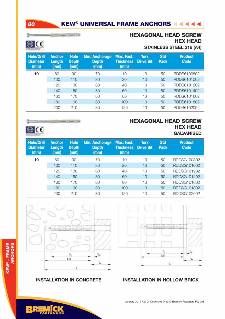
KEW® UNIVERSAL FRAME ANCHORS80
January 2011 Rev 2, Copyright © 2010 Bremick Fasteners Pty Ltd
10 80 90 70 10 13 50 RDDS6100802 100 110 80 20 13 50 RDDS6101002 120 130 80 40 13 50 RDDS6101202 140 150 80 60 13 50 RDDS6101402 160 170 80 80 13 50 RDDS6101602 180 190 80 100 13 50 RDDS6101802 200 210 80 120 13 50 RDDS6102002
10 80 90 70 10 13 50 RDDSG100802 100 110 80 20 13 50 RDDSG101002 120 130 80 40 13 50 RDDSG101202 140 150 80 60 13 50 RDDSG101402 160 170 80 80 13 50 RDDSG101602 180 190 80 100 13 50 RDDSG101802 200 210 80 120 13 50 RDDSG102002
Hole/Drill Anchor Hole Min. Anchorage Max. Fast. Torx Std Product Diameter Length Depth Depth Thickness Drive Bit Pack Code (mm) (mm) (mm) (mm) (mm)
Hole/Drill Anchor Hole Min. Anchorage Max. Fast. Torx Std Product Diameter Length Depth Depth Thickness Drive Bit Pack Code (mm) (mm) (mm) (mm) (mm)
HEXAGONAL HEAD SCREWHEX HEAD
STAINLESS STEEL 316 (A4)
HEXAGONAL HEAD SCREWHEX HEADGALVANISED
KE
W® -
FR
AM
EA
NC
HO
RS
INSTALLATION IN CONCRETE INSTALLATION IN HOLLOW BRICK
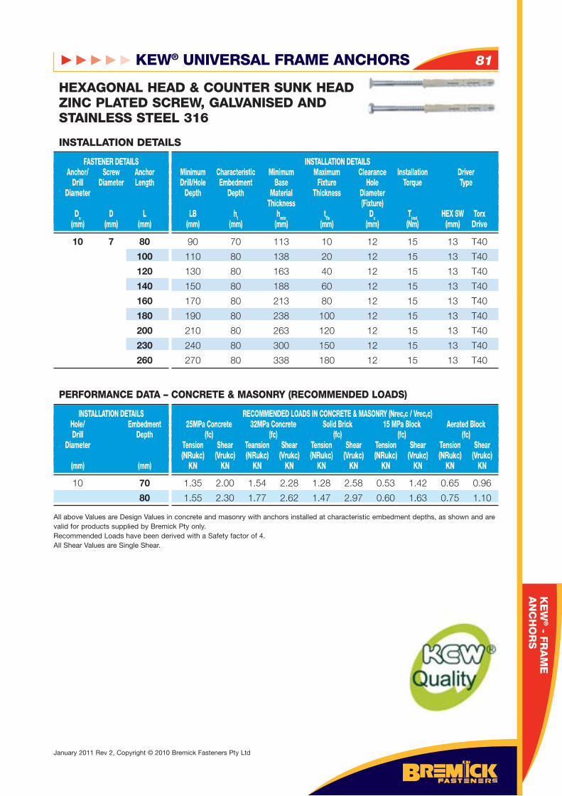
KEW® UNIVERSAL FRAME ANCHORS 81
January 2011 Rev 2, Copyright © 2010 Bremick Fasteners Pty Ltd
10 7 80
100
120
140
160
180
200
230
260
FASTENER DETAILS Anchor/ Screw Anchor Drill Diameter Length Diameter
Do D L (mm) (mm) (mm)
INSTALLATION DETAILS Minimum Characteristic Minimum Maximum Clearance Installation Driver Drill/Hole Embedment Base Fixture Hole Torque Type Depth Depth Material Thickness Diameter Thickness (Fixture) LB ht hmin tfi x Dc Tinst HEX SW Torx (mm) (mm) (mm) (mm) (mm) (Nm) (mm) Drive
INSTALLATION DETAILS
90 70 113 10 12 15 13 T40
110 80 138 20 12 15 13 T40
130 80 163 40 12 15 13 T40
150 80 188 60 12 15 13 T40
170 80 213 80 12 15 13 T40
190 80 238 100 12 15 13 T40
210 80 263 120 12 15 13 T40
240 80 300 150 12 15 13 T40
270 80 338 180 12 15 13 T40
HEXAGONAL HEAD & COUNTER SUNK HEAD ZINC PLATED SCREW, GALVANISED AND STAINLESS STEEL 316
10 70
80
INSTALLATION DETAILS Hole/ Embedment Drill Depth Diameter (mm) (mm)
RECOMMENDED LOADS IN CONCRETE & MASONRY (Nrec,c / Vrec,c) 25MPa Concrete 32MPa Concrete Solid Brick 15 MPa Block Aerated Block (fc) (fc) (fc) (fc) (fc) Tension Shear Teansion Shear Tension Shear Tension Shear Tension Shear (NRukc) (Vrukc) (NRukc) (Vrukc) (NRukc) (Vrukc) (NRukc) (Vrukc) (NRukc) (Vrukc) KN KN KN KN KN KN KN KN KN KN
1.35 2.00 1.54 2.28 1.28 2.58 0.53 1.42 0.65 0.96
1.55 2.30 1.77 2.62 1.47 2.97 0.60 1.63 0.75 1.10
All above Values are Design Values in concrete and masonry with anchors installed at characteristic embedment depths, as shown and are valid for products supplied by Bremick Pty only. Recommended Loads have been derived with a Safety factor of 4.All Shear Values are Single Shear.
PERFORMANCE DATA – CONCRETE & MASONRY (RECOMMENDED LOADS)
KE
W® - F
RA
ME
AN
CH
OR
S
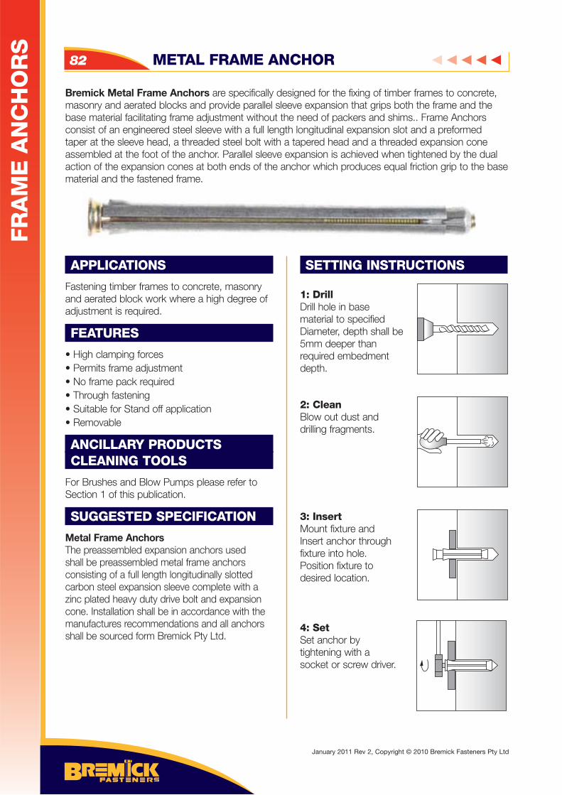
METAL FRAME ANCHOR82
Bremick Metal Frame Anchors are specifically designed for the fixing of timber frames to concrete, masonry and aerated blocks and provide parallel sleeve expansion that grips both the frame and the base material facilitating frame adjustment without the need of packers and shims.. Frame Anchors consist of an engineered steel sleeve with a full length longitudinal expansion slot and a preformed taper at the sleeve head, a threaded steel bolt with a tapered head and a threaded expansion cone assembled at the foot of the anchor. Parallel sleeve expansion is achieved when tightened by the dual action of the expansion cones at both ends of the anchor which produces equal friction grip to the base material and the fastened frame.
APPLICATIONS
Fastening timber frames to concrete, masonry and aerated block work where a high degree of adjustment is required.
FEATURES
• High clamping forces• Permits frame adjustment• No frame pack required• Through fastening• Suitable for Stand off application• Removable
ANCILLARY PRODUCTSCLEANING TOOLS
For Brushes and Blow Pumps please refer to Section 1 of this publication.
SUGGESTED SPECIFICATION
Metal Frame AnchorsThe preassembled expansion anchors used shall be preassembled metal frame anchors consisting of a full length longitudinally slotted carbon steel expansion sleeve complete with a zinc plated heavy duty drive bolt and expansion cone. Installation shall be in accordance with the manufactures recommendations and all anchors shall be sourced form Bremick Pty Ltd.
SETTING INSTRUCTIONS
1: DrillDrill hole in base material to specifiedDiameter, depth shall be5mm deeper thanrequired embedment depth.
2: CleanBlow out dust anddrilling fragments.
3: InsertMount fixture andInsert anchor throughfixture into hole. Position fixture todesired location.
4: SetSet anchor by tightening with a socket or screw driver.
FR
AM
E A
NC
HO
RS
January 2011 Rev 2, Copyright © 2010 Bremick Fasteners Pty Ltd
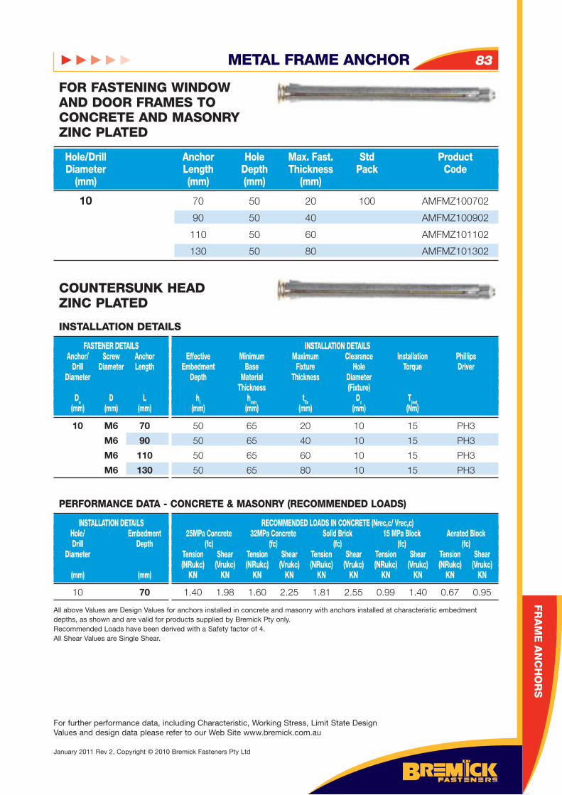
10 70 50 20 100 AMFMZ100702
90 50 40 AMFMZ100902
110 50 60 AMFMZ101102
130 50 80 AMFMZ101302
Hole/Drill Anchor Hole Max. Fast. Std Product Diameter Length Depth Thickness Pack Code (mm) (mm) (mm) (mm)
FOR FASTENING WINDOW AND DOOR FRAMES TO CONCRETE AND MASONRYZINC PLATED
METAL FRAME ANCHOR 83
FR
AM
E A
NC
HO
RS
10 M6 70
M6 90
M6 110
M6 130
FASTENER DETAILS Anchor/ Screw Anchor Drill Diameter Length Diameter
Do D L (mm) (mm) (mm)
INSTALLATION DETAILS Effective Minimum Maximum Clearance Installation Phillips Embedment Base Fixture Hole Torque Driver Depth Material Thickness Diameter Thickness (Fixture) ht hmin tfi x Dc Tinst (mm) (mm) (mm) (mm) (Nm)
INSTALLATION DETAILS
50 65 20 10 15 PH3
50 65 40 10 15 PH3
50 65 60 10 15 PH3
50 65 80 10 15 PH3
COUNTERSUNK HEADZINC PLATED
10 70
INSTALLATION DETAILS Hole/ Embedment Drill Depth Diameter (mm) (mm)
RECOMMENDED LOADS IN CONCRETE (Nrec,c/ Vrec,c) 25MPa Concrete 32MPa Concrete Solid Brick 15 MPa Block Aerated Block (fc) (fc) (fc) (fc) (fc) Tension Shear Tension Shear Tension Shear Tension Shear Tension Shear (NRukc) (Vrukc) (NRukc) (Vrukc) (NRukc) (Vrukc) (NRukc) (Vrukc) (NRukc) (Vrukc) KN KN KN KN KN KN KN KN KN KN
1.40 1.98 1.60 2.25 1.81 2.55 0.99 1.40 0.67 0.95
All above Values are Design Values for anchors installed in concrete and masonry with anchors installed at characteristic embedment depths, as shown and are valid for products supplied by Bremick Pty only.Recommended Loads have been derived with a Safety factor of 4.All Shear Values are Single Shear.
PERFORMANCE DATA - CONCRETE & MASONRY (RECOMMENDED LOADS)
For further performance data, including Characteristic, Working Stress, Limit State Design Values and design data please refer to our Web Site www.bremick.com.au
January 2011 Rev 2, Copyright © 2010 Bremick Fasteners Pty Ltd
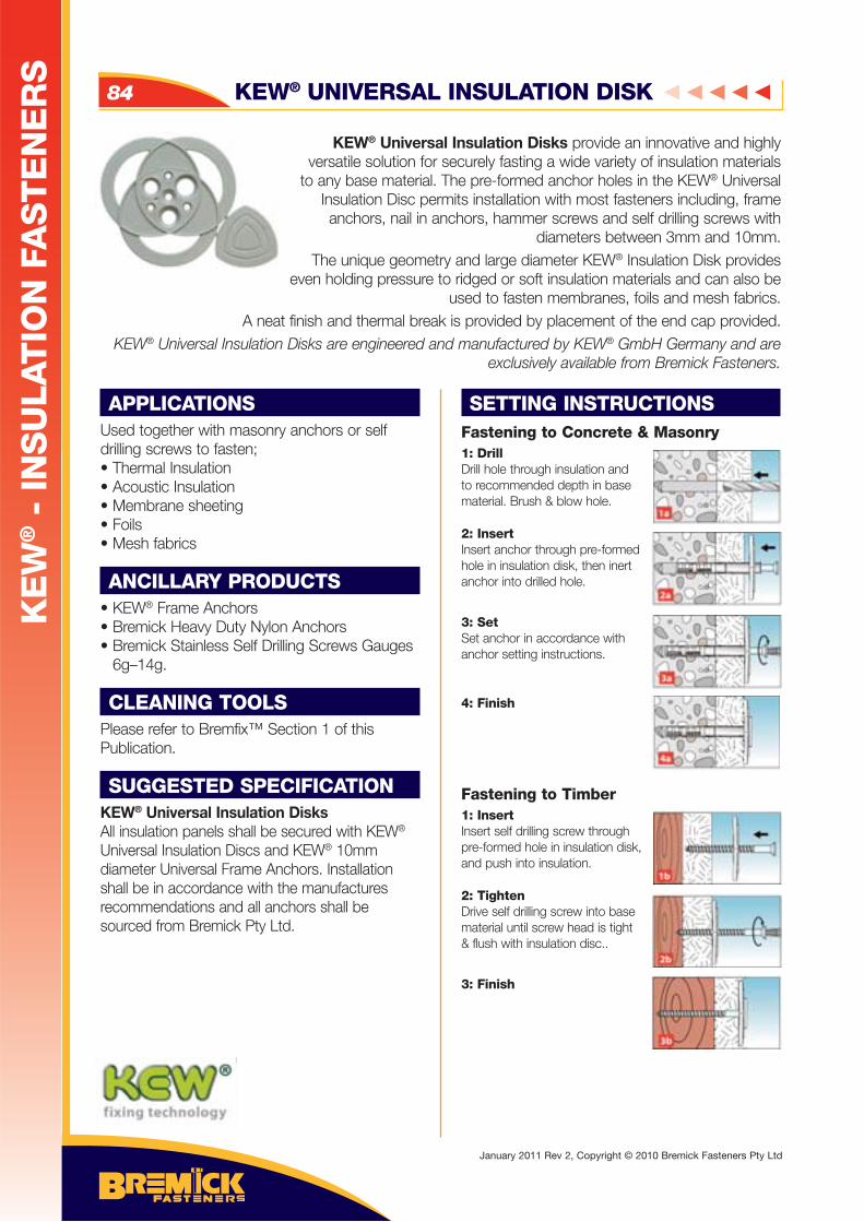
APPLICATIONSUsed together with masonry anchors or self drilling screws to fasten;• Thermal Insulation• Acoustic Insulation• Membrane sheeting• Foils• Mesh fabrics
ANCILLARY PRODUCTS• KEW® Frame Anchors• Bremick Heavy Duty Nylon Anchors• Bremick Stainless Self Drilling Screws Gauges
6g–14g.
CLEANING TOOLSPlease refer to Bremfix™ Section 1 of this Publication.
SUGGESTED SPECIFICATIONKEW® Universal Insulation DisksAll insulation panels shall be secured with KEW® Universal Insulation Discs and KEW® 10mm diameter Universal Frame Anchors. Installation shall be in accordance with the manufactures recommendations and all anchors shall be sourced from Bremick Pty Ltd.
SETTING INSTRUCTIONSFastening to Concrete & Masonry 1: DrillDrill hole through insulation and to recommended depth in base material. Brush & blow hole.
2: InsertInsert anchor through pre-formed hole in insulation disk, then inert anchor into drilled hole.
3: SetSet anchor in accordance with anchor setting instructions.
4: Finish
Fastening to Timber 1: InsertInsert self drilling screw through pre-formed hole in insulation disk, and push into insulation.
2: TightenDrive self drilling screw into base material until screw head is tight & flush with insulation disc..
3: Finish
KEW® Universal Insulation Disks provide an innovative and highly versatile solution for securely fasting a wide variety of insulation materials
to any base material. The pre-formed anchor holes in the KEW® Universal Insulation Disc permits installation with most fasteners including, frame anchors, nail in anchors, hammer screws and self drilling screws with
diameters between 3mm and 10mm. The unique geometry and large diameter KEW® Insulation Disk provides
even holding pressure to ridged or soft insulation materials and can also be used to fasten membranes, foils and mesh fabrics.
A neat finish and thermal break is provided by placement of the end cap provided.KEW® Universal Insulation Disks are engineered and manufactured by KEW® GmbH Germany and are
exclusively available from Bremick Fasteners.
KEW® UNIVERSAL INSULATION DISK84
KE
W® -
IN
SU
LAT
ION
FA
ST
EN
ER
S
January 2011 Rev 2, Copyright © 2010 Bremick Fasteners Pty Ltd
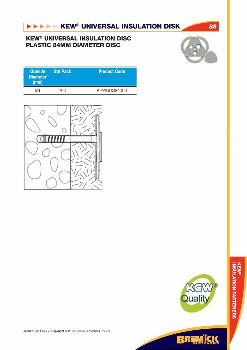
KEW® UNIVERSAL INSULATION DISK 85
January 2011 Rev 2, Copyright © 2010 Bremick Fasteners Pty Ltd
KEW® UNIVERSAL INSULATION DISCPLASTIC 84MM DIAMETER DISC
84 200 KEWUDS84000
Outside Std Pack Product Code Diameter (mm)
KE
W® -
INS
ULAT
ION
FAS
TE
NE
RS
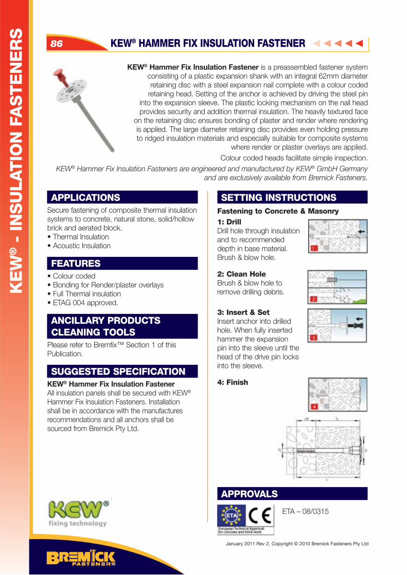
APPLICATIONSSecure fastening of composite thermal insulation systems to concrete, natural stone, solid/hollow brick and aerated block. • Thermal Insulation• Acoustic Insulation
FEATURES• Colour coded • Bonding for Render/plaster overlays• Full Thermal insulation• ETAG 004 approved.
ANCILLARY PRODUCTSCLEANING TOOLS
Please refer to Bremfix™ Section 1 of this Publication.
SUGGESTED SPECIFICATIONKEW® Hammer Fix Insulation FastenerAll insulation panels shall be secured with KEW® Hammer Fix Insulation Fasteners. Installation shall be in accordance with the manufactures recommendations and all anchors shall be sourced from Bremick Pty Ltd.
SETTING INSTRUCTIONSFastening to Concrete & Masonry 1: DrillDrill hole through insulation and to recommended depth in base material. Brush & blow hole.
2: Clean HoleBrush & blow hole to remove drilling debris.
3: Insert & SetInsert anchor into drilled hole. When fully inserted hammer the expansion pin into the sleeve until the head of the drive pin locks into the sleeve.
4: Finish
APPROVALS
ETA – 08/0315
KEW® Hammer Fix Insulation Fastener is a preassembled fastener system consisting of a plastic expansion shank with an integral 62mm diameter retaining disc with a steel expansion nail complete with a colour coded
retaining head. Setting of the anchor is achieved by driving the steel pin into the expansion sleeve. The plastic locking mechanism on the nail head provides security and addition thermal insulation. The heavily textured face
on the retaining disc ensures bonding of plaster and render where rendering is applied. The large diameter retaining disc provides even holding pressure to ridged insulation materials and especially suitable for composite systems
where render or plaster overlays are applied.Colour coded heads facilitate simple inspection.
KEW® Hammer Fix Insulation Fasteners are engineered and manufactured by KEW® GmbH Germany and are exclusively available from Bremick Fasteners.
KEW® HAMMER FIX INSULATION FASTENER86
KE
W® -
IN
SU
LAT
ION
FA
ST
EN
ER
S
January 2011 Rev 2, Copyright © 2010 Bremick Fasteners Pty Ltd
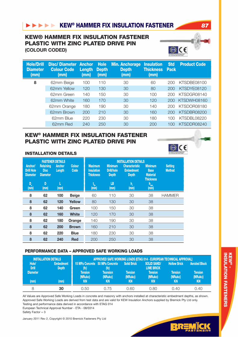
KEW® HAMMER FIX INSULATION FASTENER 87
January 2011 Rev 2, Copyright © 2010 Bremick Fasteners Pty Ltd
KE
W® -
INS
ULAT
ION
FAS
TE
NE
RS
8 62mm Beige 100 110 30 60 200 KTSDBE08100 62mm Yellow 120 130 30 80 200 KTSDYE08120 62mm Green 140 150 30 100 200 KTSDGR08140 62mm White 160 170 30 120 200 KTSDWH08160 62mm Orange 180 190 30 140 200 KTSDOR08180 62mm Brown 200 210 30 160 200 KTSDBR08200 62mm Blue 220 230 30 180 100 KTSDBL08220 62mm Red 240 250 30 200 100 KTSDDR08240
Hole/Drill Disc/ Diameter Anchor Hole Min. Anchorage Insulation Std Product Code Diameter Colour Code Length Depth Depth Thickness Pack (mm) (mm) (mm) (mm) (mm) (mm)
KEW® HAMMER FIX INSULATION FASTENERPLASTIC WITH ZINC PLATED DRIVE PIN (COLOUR CODED)
8 62 100 Beige
8 62 120 Yellow
8 62 140 Green
8 62 160 White
8 62 180 Orange
8 62 200 Brown
8 62 220 Blue
8 62 240 Red
FASTENER DETAILS Anchor/ Retaining Anchor Colour Drill Hole Disc Length Code Diameter Diameter
Do D L (mm) (mm) (mm)
INSTALLATION DETAILS Maximum Minimum Characteristic Minimum Setting Insulation Drill/hole Embedment Base Method Thickness Depth Depth Material Thickness tfi x LB ht hmin (mm) (mm) (mm) (mm)
INSTALLATION DETAILS
60 110 30 38 HAMMER
80 130 30 38
100 150 30 38
120 170 30 38
140 190 30 38
160 210 30 38
180 230 30 38
200 250 30 38
KEW® HAMMER FIX INSULATION FASTENERPLASTIC WITH ZINC PLATED DRIVE PIN
8 30
INSTALLATION DETAILS Hole/ Embedment Drill Depth Diameter (mm) (mm)
APPROVED SAFE WORKING LOADS (ETAG 014 - EUROPEAN TECHNICAL APPROVAL) 15 MPa Concrete 50 MPa Concrete Solid Brick SOLID SAND/ Hollow Brick Aerated Block (fc) (fc) LIME BRICK Tension Teansion Tension Tension Tension Tension (NRukc) (NRukc) (NRukc) (NRukc) (NRukc) (NRukc) KN KN KN KN KN KN
0.50 0.75 0.60 0.80 0.40 0.40
All Values are Approved Safe Working Loads in concrete and masonry with anchors installed at characteristic embedment depths, as shown. Approved Safe Working Loads are derived from test data and are valid for KEW Insulation Anchors supplied by Bremick Pty Ltd only.Testing and performance data derived in accordance with ETAG 014European Technical Approval Number - ETA - 08/0314Safety Factor = 3
PERFORMANCE DATA – APPROVED SAFE WORKING LOADS
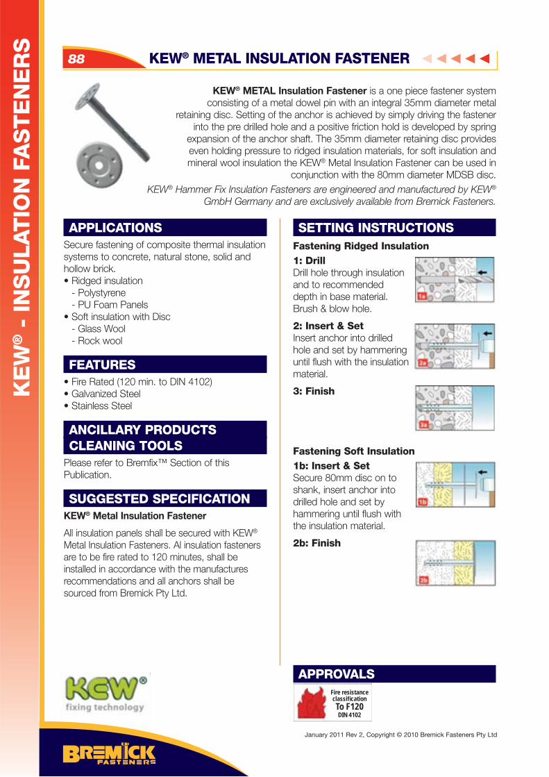
APPLICATIONSSecure fastening of composite thermal insulation systems to concrete, natural stone, solid and hollow brick. • Ridged insulation - Polystyrene - PU Foam Panels• Soft insulation with Disc - Glass Wool - Rock wool
FEATURES• Fire Rated (120 min. to DIN 4102) • Galvanized Steel• Stainless Steel
ANCILLARY PRODUCTSCLEANING TOOLS
Please refer to Bremfix™ Section of this Publication.
SUGGESTED SPECIFICATIONKEW® Metal Insulation Fastener
All insulation panels shall be secured with KEW® Metal Insulation Fasteners. Al insulation fasteners are to be fire rated to 120 minutes, shall be installed in accordance with the manufactures recommendations and all anchors shall be sourced from Bremick Pty Ltd.
SETTING INSTRUCTIONSFastening Ridged Insulation1: DrillDrill hole through insulation and to recommended depth in base material. Brush & blow hole.
2: Insert & SetInsert anchor into drilled hole and set by hammering until flush with the insulation material.
3: Finish
Fastening Soft Insulation1b: Insert & SetSecure 80mm disc on to shank, insert anchor into drilled hole and set by hammering until flush with the insulation material.
2b: Finish
APPROVALS
KEW® METAL Insulation Fastener is a one piece fastener system consisting of a metal dowel pin with an integral 35mm diameter metal
retaining disc. Setting of the anchor is achieved by simply driving the fastener into the pre drilled hole and a positive friction hold is developed by spring
expansion of the anchor shaft. The 35mm diameter retaining disc provides even holding pressure to ridged insulation materials, for soft insulation and mineral wool insulation the KEW® Metal Insulation Fastener can be used in
conjunction with the 80mm diameter MDSB disc. KEW® Hammer Fix Insulation Fasteners are engineered and manufactured by KEW®
GmbH Germany and are exclusively available from Bremick Fasteners.
KEW® METAL INSULATION FASTENER88
KE
W® -
IN
SU
LAT
ION
FA
ST
EN
ER
S
January 2011 Rev 2, Copyright © 2010 Bremick Fasteners Pty Ltd
Fire resistanceclassifi cationTo F120DIN 4102
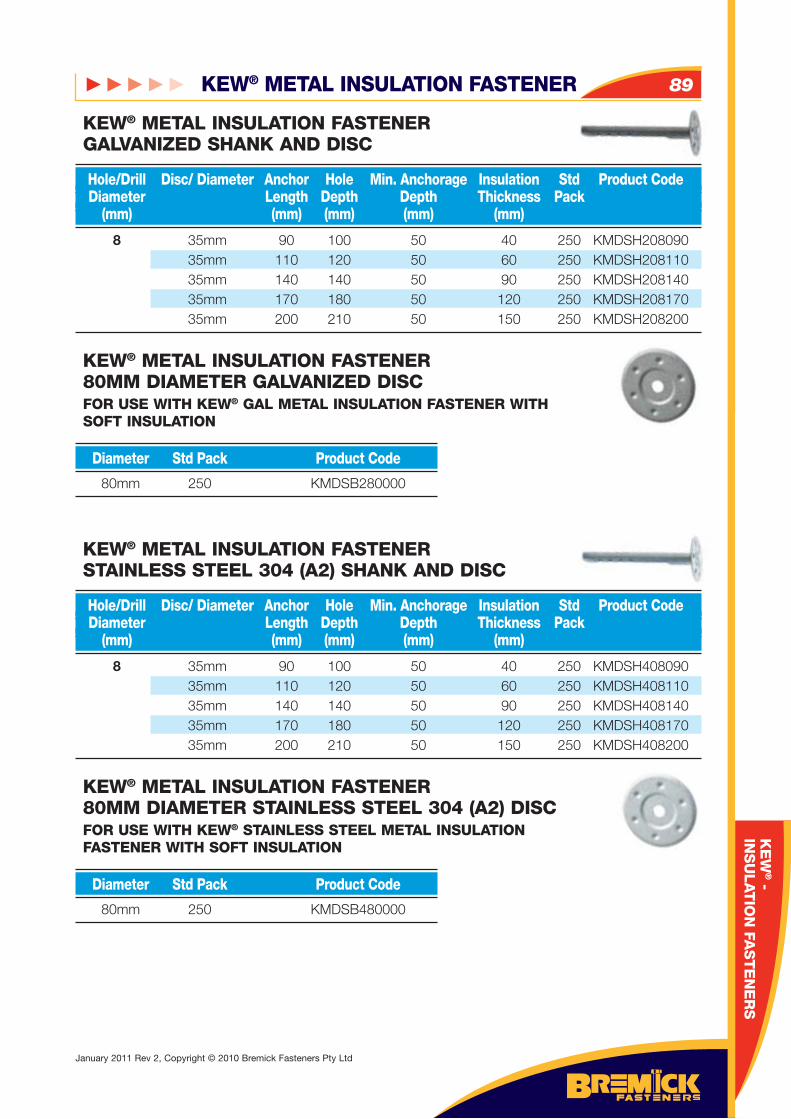
KEW® METAL INSULATION FASTENER 89
January 2011 Rev 2, Copyright © 2010 Bremick Fasteners Pty Ltd
KE
W® -
INS
ULAT
ION
FAS
TE
NE
RS
8 35mm 90 100 50 40 250 KMDSH208090 35mm 110 120 50 60 250 KMDSH208110 35mm 140 140 50 90 250 KMDSH208140 35mm 170 180 50 120 250 KMDSH208170 35mm 200 210 50 150 250 KMDSH208200
8 35mm 90 100 50 40 250 KMDSH408090 35mm 110 120 50 60 250 KMDSH408110 35mm 140 140 50 90 250 KMDSH408140 35mm 170 180 50 120 250 KMDSH408170 35mm 200 210 50 150 250 KMDSH408200
Hole/Drill Disc/ Diameter Anchor Hole Min. Anchorage Insulation Std Product Code Diameter Length Depth Depth Thickness Pack (mm) (mm) (mm) (mm) (mm)
Hole/Drill Disc/ Diameter Anchor Hole Min. Anchorage Insulation Std Product Code Diameter Length Depth Depth Thickness Pack (mm) (mm) (mm) (mm) (mm)
KEW® METAL INSULATION FASTENERGALVANIZED SHANK AND DISC
KEW® METAL INSULATION FASTENERSTAINLESS STEEL 304 (A2) SHANK AND DISC
KEW® METAL INSULATION FASTENER80MM DIAMETER GALVANIZED DISCFOR USE WITH KEW® GAL METAL INSULATION FASTENER WITH SOFT INSULATION
KEW® METAL INSULATION FASTENER80MM DIAMETER STAINLESS STEEL 304 (A2) DISCFOR USE WITH KEW® STAINLESS STEEL METAL INSULATION FASTENER WITH SOFT INSULATION
80mm 250 KMDSB280000
80mm 250 KMDSB480000
Diameter Std Pack Product Code
Diameter Std Pack Product Code
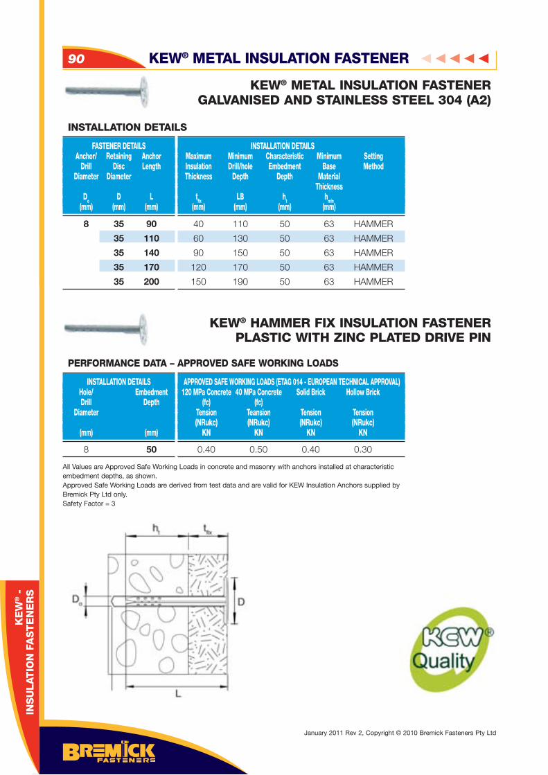
KEW® METAL INSULATION FASTENER90
January 2011 Rev 2, Copyright © 2010 Bremick Fasteners Pty Ltd
KE
W® -
IN
SU
LAT
ION
FA
ST
EN
ER
S
INSTALLATION DETAILS Maximum Minimum Characteristic Minimum Setting Insulation Drill/hole Embedment Base Method Thickness Depth Depth Material Thickness tfi x LB ht hmin (mm) (mm) (mm) (mm)
INSTALLATION DETAILS
40 110 50 63 HAMMER
60 130 50 63 HAMMER
90 150 50 63 HAMMER
120 170 50 63 HAMMER
150 190 50 63 HAMMER
KEW® METAL INSULATION FASTENERGALVANISED AND STAINLESS STEEL 304 (A2)
KEW® HAMMER FIX INSULATION FASTENERPLASTIC WITH ZINC PLATED DRIVE PIN
8 50
INSTALLATION DETAILS Hole/ Embedment Drill Depth Diameter (mm) (mm)
APPROVED SAFE WORKING LOADS (ETAG 014 - EUROPEAN TECHNICAL APPROVAL) 120 MPa Concrete 40 MPa Concrete Solid Brick Hollow Brick (fc) (fc) Tension Teansion Tension Tension (NRukc) (NRukc) (NRukc) (NRukc) KN KN KN KN
0.40 0.50 0.40 0.30
All Values are Approved Safe Working Loads in concrete and masonry with anchors installed at characteristic embedment depths, as shown.Approved Safe Working Loads are derived from test data and are valid for KEW Insulation Anchors supplied by Bremick Pty Ltd only.Safety Factor = 3
PERFORMANCE DATA – APPROVED SAFE WORKING LOADS
8 35 90
35 110
35 140
35 170
35 200
FASTENER DETAILS Anchor/ Retaining Anchor Drill Disc Length Diameter Diameter
Do D L (mm) (mm) (mm)
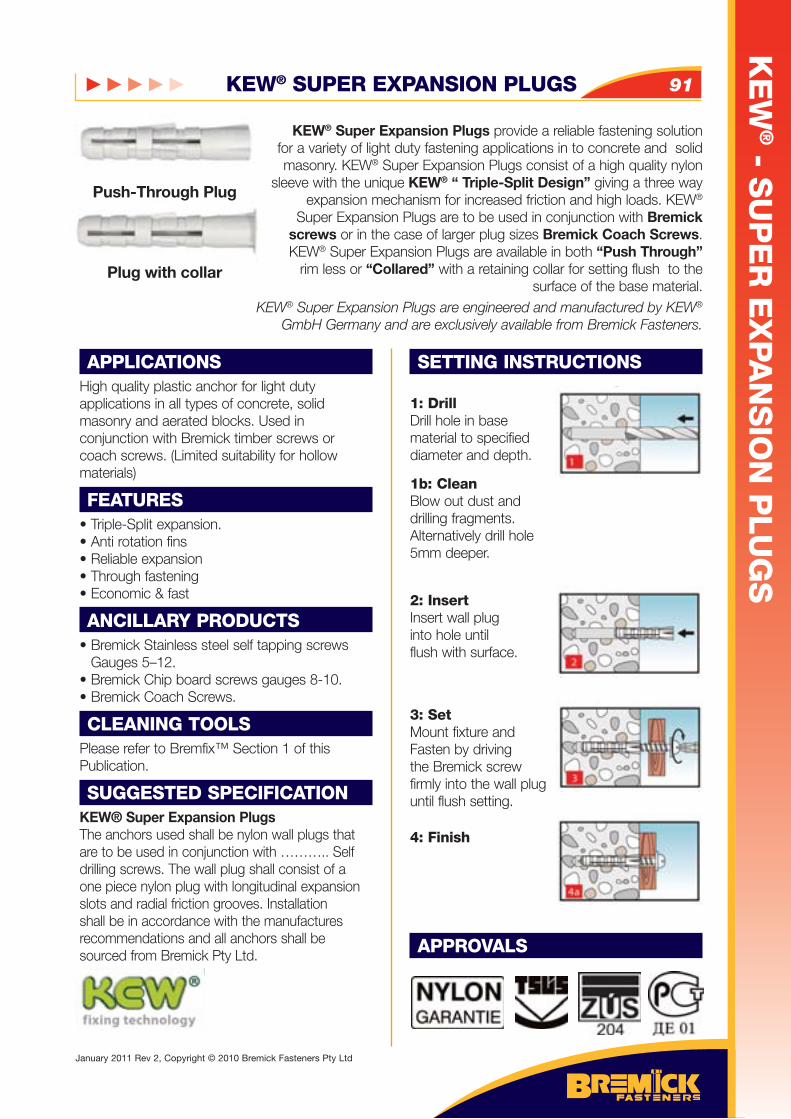
KEW® SUPER EXPANSION PLUGS 91
KE
W® - S
UP
ER
EX
PA
NS
ION
PLU
GS
January 2011 Rev 2, Copyright © 2010 Bremick Fasteners Pty Ltd
APPLICATIONSHigh quality plastic anchor for light duty applications in all types of concrete, solid masonry and aerated blocks. Used in conjunction with Bremick timber screws or coach screws. (Limited suitability for hollow materials)
FEATURES• Triple-Split expansion. • Anti rotation fins • Reliable expansion • Through fastening• Economic & fast
ANCILLARY PRODUCTS• Bremick Stainless steel self tapping screws
Gauges 5–12.• Bremick Chip board screws gauges 8-10.• Bremick Coach Screws.
CLEANING TOOLSPlease refer to Bremfix™ Section 1 of this Publication.
SUGGESTED SPECIFICATIONKEW® Super Expansion PlugsThe anchors used shall be nylon wall plugs that are to be used in conjunction with ……….. Self drilling screws. The wall plug shall consist of a one piece nylon plug with longitudinal expansion slots and radial friction grooves. Installation shall be in accordance with the manufactures recommendations and all anchors shall be sourced from Bremick Pty Ltd.
SETTING INSTRUCTIONS
1: DrillDrill hole in base material to specifieddiameter and depth.
1b: CleanBlow out dust anddrilling fragments.Alternatively drill hole5mm deeper.
2: InsertInsert wall pluginto hole until flush with surface.
3: SetMount fixture andFasten by drivingthe Bremick screwfirmly into the wall pluguntil flush setting.
4: Finish
APPROVALS
KEW® Super Expansion Plugs provide a reliable fastening solution for a variety of light duty fastening applications in to concrete and solid masonry. KEW® Super Expansion Plugs consist of a high quality nylon
sleeve with the unique KEW® “ Triple-Split Design” giving a three way expansion mechanism for increased friction and high loads. KEW®
Super Expansion Plugs are to be used in conjunction with Bremick screws or in the case of larger plug sizes Bremick Coach Screws. KEW® Super Expansion Plugs are available in both “Push Through”
rim less or “Collared” with a retaining collar for setting flush to the surface of the base material.
KEW® Super Expansion Plugs are engineered and manufactured by KEW® GmbH Germany and are exclusively available from Bremick Fasteners.
Push-Through Plug
Plug with collar
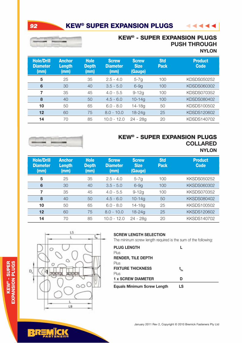
KEW® - SUPER EXPANSION PLUGSPUSH THROUGH
NYLON
KEW® - SUPER EXPANSION PLUGSCOLLARED
NYLON
5 25 35 2.5 - 4.0 5-7g 100 KDSDS050252
6 30 40 3.5 - 5.0 6-9g 100 KDSDS060302
7 35 45 4.0 - 5.5 9-12g 100 KDSDS070352
8 40 50 4.5 - 6.0 10-14g 100 KDSDS080402
10 50 65 6.0 - 8.0 14-18g 50 KDSDS100502
12 60 75 8.0 - 10.0 18-24g 25 KDSDS120602
14 70 85 10.0 - 12.0 24 - 28g 20 KDSDS140702
5 25 35 2.5 - 4.0 5-7g 100 KKSDS050252
6 30 40 3.5 - 5.0 6-9g 100 KKSDS060302
7 35 45 4.0 - 5.5 9-12g 100 KKSDS070352
8 40 50 4.5 - 6.0 10-14g 50 KKSDS080402
10 50 65 6.0 - 8.0 14-18g 25 KKSDS100502
12 60 75 8.0 - 10.0 18-24g 25 KKSDS120602
14 70 85 10.0 - 12.0 24 - 28g 20 KKSDS140702
Hole/Drill Anchor Hole Screw Screw Std Product Diameter Length Depth Diameter Size Pack Code (mm) (mm) (mm) (mm) (Gauge)
Hole/Drill Anchor Hole Screw Screw Std Product Diameter Length Depth Diameter Size Pack Code (mm) (mm) (mm) (mm) (Gauge)
SCREW LENGTH SELECTION The mininum screw length required is the sum of the following:
PLUG LENGTH LPlus RENDER, TILE DEPTH Plus FIXTURE THICKNESS tfix
Plus 1 x SCREW DIAMETER D
Equals Minimum Screw Length LS
KEW® SUPER EXPANSION PLUGS92
January 2011 Rev 2, Copyright © 2010 Bremick Fasteners Pty Ltd
KE
W® -
SU
PE
RE
XPA
NS
ION
PLU
GS
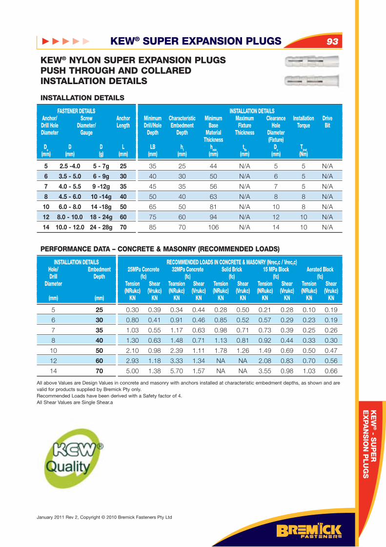
KEW® SUPER EXPANSION PLUGS 93
January 2011 Rev 2, Copyright © 2010 Bremick Fasteners Pty Ltd
KE
W® - S
UP
ER
EX
PA
NS
ION
PLU
GS
5 2.5 -4.0 5 - 7g 25
6 3.5 - 5.0 6 - 9g 30
7 4.0 - 5.5 9 -12g 35
8 4.5 - 6.0 10 -14g 40
10 6.0 - 8.0 14 -18g 50
12 8.0 - 10.0 18 - 24g 60
14 10.0 - 12.0 24 - 28g 70
FASTENER DETAILS Anchor/ Screw Anchor Drill Hole Diameter/ Length Diameter Gauge
Do D D L (mm) (mm) (g) (mm)
INSTALLATION DETAILS Minimum Characteristic Minimum Maximum Clearance Installation Drive Drill/Hole Embedment Base Fixture Hole Torque Bit Depth Depth Material Thickness Diameter Thickness (Fixture) LB ht hmin tfi x Dc Tinst (mm) (mm) (mm) (mm) (mm) (Nm)
INSTALLATION DETAILS
35 25 44 N/A 5 5 N/A
40 30 50 N/A 6 5 N/A
45 35 56 N/A 7 5 N/A
50 40 63 N/A 8 8 N/A
65 50 81 N/A 10 8 N/A
75 60 94 N/A 12 10 N/A
85 70 106 N/A 14 10 N/A
KEW® NYLON SUPER EXPANSION PLUGSPUSH THROUGH AND COLLAREDINSTALLATION DETAILS
5 25
6 30
7 35
8 40
10 50
12 60
14 70
INSTALLATION DETAILS Hole/ Embedment Drill Depth Diameter (mm) (mm)
RECOMMENDED LOADS IN CONCRETE & MASONRY (Nrec,c / Vrec,c) 25MPa Concrete 32MPa Concrete Solid Brick 15 MPa Block Aerated Block (fc) (fc) (fc) (fc) (fc) Tension Shear Teansion Shear Tension Shear Tension Shear Tension Shear (NRukc) (Vrukc) (NRukc) (Vrukc) (NRukc) (Vrukc) (NRukc) (Vrukc) (NRukc) (Vrukc) KN KN KN KN KN KN KN KN KN KN
0.30 0.39 0.34 0.44 0.28 0.50 0.21 0.28 0.10 0.19
0.80 0.41 0.91 0.46 0.85 0.52 0.57 0.29 0.23 0.19
1.03 0.55 1.17 0.63 0.98 0.71 0.73 0.39 0.25 0.26
1.30 0.63 1.48 0.71 1.13 0.81 0.92 0.44 0.33 0.30
2.10 0.98 2.39 1.11 1.78 1.26 1.49 0.69 0.50 0.47
2.93 1.18 3.33 1.34 NA NA 2.08 0.83 0.70 0.56
5.00 1.38 5.70 1.57 NA NA 3.55 0.98 1.03 0.66
All above Values are Design Values in concrete and masonry with anchors installed at characteristic embedment depths, as shown and are valid for products supplied by Bremick Pty only. Recommended Loads have been derived with a Safety factor of 4.All Shear Values are Single Shear.a
PERFORMANCE DATA – CONCRETE & MASONRY (RECOMMENDED LOADS)
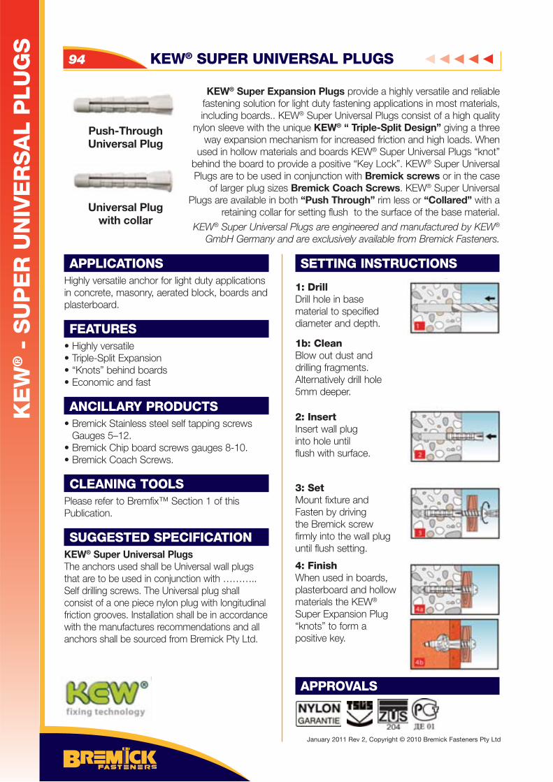
KEW® SUPER UNIVERSAL PLUGS94
KE
W® -
SU
PE
R U
NIV
ER
SA
L P
LU
GS
January 2011 Rev 2, Copyright © 2010 Bremick Fasteners Pty Ltd
APPLICATIONSHighly versatile anchor for light duty applications in concrete, masonry, aerated block, boards and plasterboard.
FEATURES• Highly versatile• Triple-Split Expansion• “Knots” behind boards • Economic and fast
ANCILLARY PRODUCTS• Bremick Stainless steel self tapping screws
Gauges 5–12.• Bremick Chip board screws gauges 8-10.• Bremick Coach Screws.
CLEANING TOOLSPlease refer to Bremfix™ Section 1 of this Publication.
SUGGESTED SPECIFICATIONKEW® Super Universal PlugsThe anchors used shall be Universal wall plugs that are to be used in conjunction with ……….. Self drilling screws. The Universal plug shall consist of a one piece nylon plug with longitudinal friction grooves. Installation shall be in accordance with the manufactures recommendations and all anchors shall be sourced from Bremick Pty Ltd.
SETTING INSTRUCTIONS
1: DrillDrill hole in base material to specifieddiameter and depth.
1b: CleanBlow out dust anddrilling fragments.Alternatively drill hole5mm deeper.
2: InsertInsert wall pluginto hole until flush with surface.
3: SetMount fixture andFasten by drivingthe Bremick screwfirmly into the wall pluguntil flush setting.
4: FinishWhen used in boards, plasterboard and hollow materials the KEW® Super Expansion Plug “knots” to form a positive key.
APPROVALS
KEW® Super Expansion Plugs provide a highly versatile and reliable fastening solution for light duty fastening applications in most materials, including boards.. KEW® Super Universal Plugs consist of a high quality
nylon sleeve with the unique KEW® “ Triple-Split Design” giving a three way expansion mechanism for increased friction and high loads. When
used in hollow materials and boards KEW® Super Universal Plugs “knot” behind the board to provide a positive “Key Lock”. KEW® Super Universal Plugs are to be used in conjunction with Bremick screws or in the case
of larger plug sizes Bremick Coach Screws. KEW® Super Universal Plugs are available in both “Push Through” rim less or “Collared” with a
retaining collar for setting flush to the surface of the base material.KEW® Super Universal Plugs are engineered and manufactured by KEW®
GmbH Germany and are exclusively available from Bremick Fasteners.
Push-Through Universal Plug
Universal Plug with collar
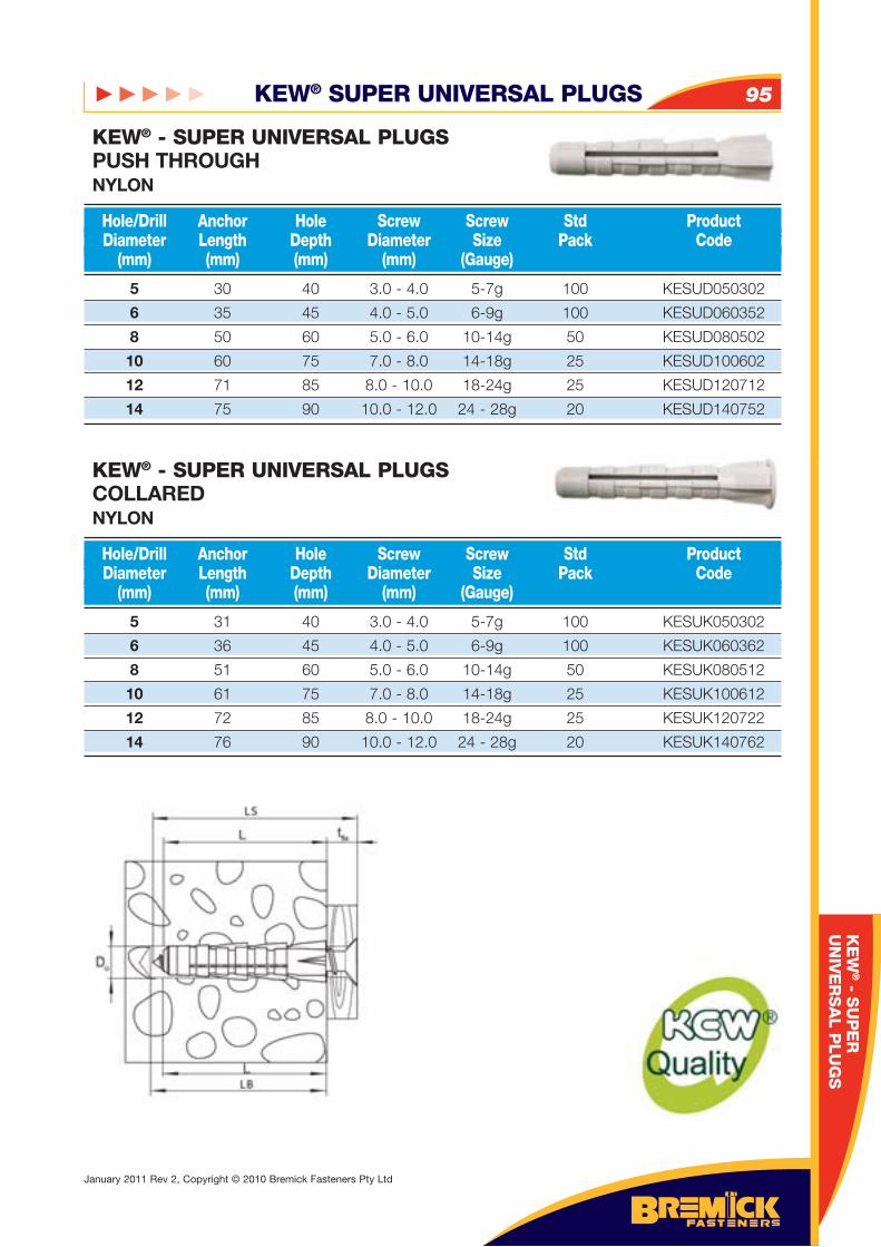
KEW® SUPER UNIVERSAL PLUGS 95
January 2011 Rev 2, Copyright © 2010 Bremick Fasteners Pty Ltd
KE
W® - S
UP
ER
UN
IVE
RS
AL P
LU
GS
KEW® - SUPER UNIVERSAL PLUGSPUSH THROUGHNYLON
KEW® - SUPER UNIVERSAL PLUGSCOLLARED NYLON
5 30 40 3.0 - 4.0 5-7g 100 KESUD050302
6 35 45 4.0 - 5.0 6-9g 100 KESUD060352
8 50 60 5.0 - 6.0 10-14g 50 KESUD080502
10 60 75 7.0 - 8.0 14-18g 25 KESUD100602
12 71 85 8.0 - 10.0 18-24g 25 KESUD120712
14 75 90 10.0 - 12.0 24 - 28g 20 KESUD140752
5 31 40 3.0 - 4.0 5-7g 100 KESUK050302
6 36 45 4.0 - 5.0 6-9g 100 KESUK060362
8 51 60 5.0 - 6.0 10-14g 50 KESUK080512
10 61 75 7.0 - 8.0 14-18g 25 KESUK100612
12 72 85 8.0 - 10.0 18-24g 25 KESUK120722
14 76 90 10.0 - 12.0 24 - 28g 20 KESUK140762
Hole/Drill Anchor Hole Screw Screw Std Product Diameter Length Depth Diameter Size Pack Code (mm) (mm) (mm) (mm) (Gauge)
Hole/Drill Anchor Hole Screw Screw Std Product Diameter Length Depth Diameter Size Pack Code (mm) (mm) (mm) (mm) (Gauge)
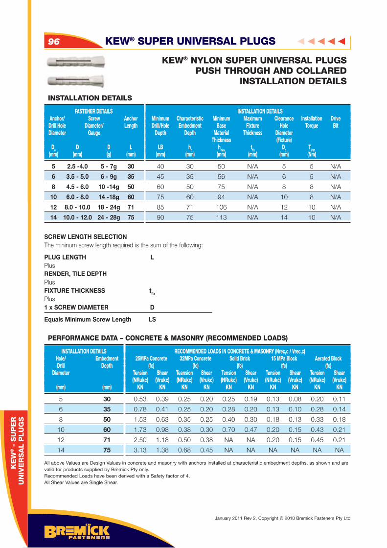
KEW® SUPER UNIVERSAL PLUGS96
January 2011 Rev 2, Copyright © 2010 Bremick Fasteners Pty Ltd
KE
W® -
SU
PE
RU
NIV
ER
SA
L P
LU
GS
5 2.5 -4.0 5 - 7g 30
6 3.5 - 5.0 6 - 9g 35
8 4.5 - 6.0 10 -14g 50
10 6.0 - 8.0 14 -18g 60
12 8.0 - 10.0 18 - 24g 71
14 10.0 - 12.0 24 - 28g 75
FASTENER DETAILS Anchor/ Screw Anchor Drill Hole Diameter/ Length Diameter Gauge
Do D D L (mm) (mm) (g) (mm)
INSTALLATION DETAILS Minimum Characteristic Minimum Maximum Clearance Installation Drive Drill/Hole Embedment Base Fixture Hole Torque Bit Depth Depth Material Thickness Diameter Thickness (Fixture) LB ht hmin tfi x Dc Tinst (mm) (mm) (mm) (mm) (mm) (Nm)
INSTALLATION DETAILS
40 30 50 N/A 5 5 N/A
45 35 56 N/A 6 5 N/A
60 50 75 N/A 8 8 N/A
75 60 94 N/A 10 8 N/A
85 71 106 N/A 12 10 N/A
90 75 113 N/A 14 10 N/A
KEW® NYLON SUPER UNIVERSAL PLUGSPUSH THROUGH AND COLLARED
INSTALLATION DETAILS
5 30
6 35
8 50
10 60
12 71
14 75
INSTALLATION DETAILS Hole/ Embedment Drill Depth Diameter (mm) (mm)
RECOMMENDED LOADS IN CONCRETE & MASONRY (Nrec,c / Vrec,c) 25MPa Concrete 32MPa Concrete Solid Brick 15 MPa Block Aerated Block (fc) (fc) (fc) (fc) (fc) Tension Shear Teansion Shear Tension Shear Tension Shear Tension Shear (NRukc) (Vrukc) (NRukc) (Vrukc) (NRukc) (Vrukc) (NRukc) (Vrukc) (NRukc) (Vrukc) KN KN KN KN KN KN KN KN KN KN
0.53 0.39 0.25 0.20 0.25 0.19 0.13 0.08 0.20 0.11
0.78 0.41 0.25 0.20 0.28 0.20 0.13 0.10 0.28 0.14
1.53 0.63 0.35 0.25 0.40 0.30 0.18 0.13 0.33 0.18
1.73 0.98 0.38 0.30 0.70 0.47 0.20 0.15 0.43 0.21
2.50 1.18 0.50 0.38 NA NA 0.20 0.15 0.45 0.21
3.13 1.38 0.68 0.45 NA NA NA NA NA NA
All above Values are Design Values in concrete and masonry with anchors installed at characteristic embedment depths, as shown and are valid for products supplied by Bremick Pty only. Recommended Loads have been derived with a Safety factor of 4.All Shear Values are Single Shear.
PERFORMANCE DATA – CONCRETE & MASONRY (RECOMMENDED LOADS)
SCREW LENGTH SELECTION The mininum screw length required is the sum of the following:
PLUG LENGTH LPlus RENDER, TILE DEPTH Plus FIXTURE THICKNESS tfix
Plus 1 x SCREW DIAMETER D
Equals Minimum Screw Length LS
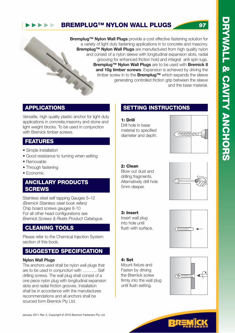
BREMPLUG™ NYLON WALL PLUGS 97
DR
YW
ALL &
CA
VIT
Y A
NC
HO
RS
January 2011 Rev 2, Copyright © 2010 Bremick Fasteners Pty Ltd
Bremplug™ Nylon Wall Plugs provide a cost effective fastening solution for a variety of light duty fastening applications in to concrete and masonry.
Bremplug™ Nylon Wall Plugs are manufactured from high quality nylon and consist of a nylon sleeve with longitudinal expansion slots, radial
grooving for enhanced friction hold and integral anti spin lugs. Bremplug™ Nylon Wall Plugs are to be used with Bremick 8
and 10g timber screws. Expansion is achieved by driving the timber screw in to the Bremplug™ which expands the sleeve
generating controlled friction grip between the sleeve and the base material.
APPLICATIONS
Versatile, high quality plastic anchor for light duty applications in concrete,masonry and stone and light weight blocks. To be used in conjunction with Bremick timber screws.
FEATURES
• Simple installation • Good resistance to turning when setting • Removable • Through fastening• Economic
ANCILLARY PRODUCTSSCREWS
Stainless steel self tapping Gauges 5–12(Bremick Stainless steel book refers)Chip board screws gauges 8-10For all other head configurations seeBremick Screws & Rivets Product Catalogue.
CLEANING TOOLS
Please refer to the Chemical Injection System section of this book.
SUGGESTED SPECIFICATION
Nylon Wall PlugsThe anchors used shall be nylon wall plugs that are to be used in conjunction with ……….. Self drilling screws. The wall plug shall consist of a one piece nylon plug with longitudinal expansion slots and radial friction grooves. Installation shall be in accordance with the manufactures recommendations and all anchors shall be sourced form Bremick Pty Ltd.
SETTING INSTRUCTIONS
1: DrillDrill hole in base material to specifieddiameter and depth.
2: CleanBlow out dust anddrilling fragments.Alternatively drill hole5mm deeper.
3: InsertInsert wall pluginto hole until flush with surface.
4: SetMount fixture andFasten by drivingthe Bremick screwfirmly into the wall pluguntil flush setting.
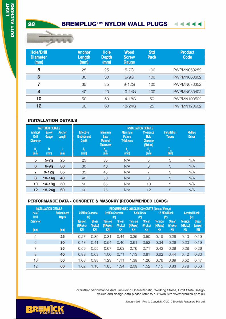
5 25 25 5-7G 100 PWPMN050252
6 30 30 6-9G 100 PWPMN060302
7 35 35 9-12G 100 PWPMN070352
8 40 40 10-14G 100 PWPMN080402
10 50 50 14-18G 50 PWPMN100502
12 60 60 18-24G 25 PWPMN120602
Hole/Drill Anchor Hole Wood Std Product Diameter Length Depth Screw Pack Code (mm) (mm) (mm) Gauge
5 5-7g 25
6 6-9g 30
7 9-12g 35
8 10-14g 40
10 14-18g 50
12 18-24g 60
FASTENER DETAILS Anchor/ Screw Anchor Drill Gauge Length Diameter
Do D L (mm) (mm) (mm)
INSTALLATION DETAILS Effective Minimum Maximum Clearance Installation Phillips Embedment Base Fixture Hole Torque Driver Depth Material Thickness Diameter Thickness (Fixture) ht hmin tfi x Dc Tinst (mm) (mm) (mm) (mm) (Nm)
INSTALLATION DETAILS
25 35 N/A 5 5 N/A
30 40 N/A 6 5 N/A
35 45 N/A 7 5 N/A
40 50 N/A 8 5 N/A
50 65 N/A 10 5 N/A
60 75 N/A 12 5 N/A
5 25
6 30
7 35
8 40
10 50
12 60
INSTALLATION DETAILS Hole/ Embedment Drill Depth Diameter (mm) (mm)
RECOMMENDED LOADS IN CONCRETE (Nrec,c/ Vrec,c) 25MPa Concrete 32MPa Concrete Solid Brick 15 MPa Block Aerated Block (fc) (fc) (fc) (fc) (fc) Tension Shear Tension Shear Tension Shear Tension Shear Tension Shear (NRukc) (Vrukc) (NRukc) (Vrukc) (NRukc) (Vrukc) (NRukc) (Vrukc) (NRukc) (Vrukc) KN KN KN KN KN KN KN KN KN KN
PERFORMANCE DATA - CONCRETE & MASONRY (RECOMMENDED LOADS)
0.27 0.39 0.31 0.44 0.35 0.50 0.19 0.28 0.13 0.19
0.48 0.41 0.54 0.46 0.61 0.52 0.34 0.29 0.23 0.19
0.59 0.55 0.67 0.63 0.76 0.71 0.42 0.39 0.28 0.26
0.88 0.63 1.00 0.71 1.13 0.81 0.62 0.44 0.42 0.30
1.08 0.98 1.23 1.11 1.39 1.26 0.76 0.69 0.52 0.47
1.62 1.18 1.85 1.34 2.09 1.52 1.15 0.83 0.78 0.56
BREMPLUG™ NYLON WALL PLUGS98
LIG
HT
D
UT
Y A
NC
HO
RS
For further performance data, including Characteristic, Working Stress, Limit State Design Values and design data please refer to our Web Site www.bremick.com.au
January 2011 Rev 2, Copyright © 2010 Bremick Fasteners Pty Ltd
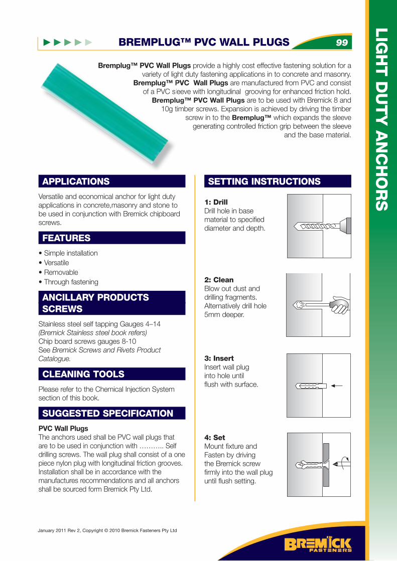
BREMPLUG™ PVC WALL PLUGS 99
LIG
HT
DU
TY
AN
CH
OR
S
January 2011 Rev 2, Copyright © 2010 Bremick Fasteners Pty Ltd
Bremplug™ PVC Wall Plugs provide a highly cost effective fastening solution for a variety of light duty fastening applications in to concrete and masonry.
Bremplug™ PVC Wall Plugs are manufactured from PVC and consist of a PVC sleeve with longitudinal grooving for enhanced friction hold.
Bremplug™ PVC Wall Plugs are to be used with Bremick 8 and 10g timber screws. Expansion is achieved by driving the timber
screw in to the Bremplug™ which expands the sleeve generating controlled friction grip between the sleeve
and the base material.
APPLICATIONS
Versatile and economical anchor for light duty applications in concrete,masonry and stone to be used in conjunction with Bremick chipboard screws.
FEATURES
• Simple installation • Versatile • Removable • Through fastening
ANCILLARY PRODUCTSSCREWS
Stainless steel self tapping Gauges 4–14(Bremick Stainless steel book refers)Chip board screws gauges 8-10See Bremick Screws and Rivets Product Catalogue.
CLEANING TOOLS
Please refer to the Chemical Injection System section of this book.
SUGGESTED SPECIFICATION
PVC Wall PlugsThe anchors used shall be PVC wall plugs that are to be used in conjunction with ……….. Self drilling screws. The wall plug shall consist of a one piece nylon plug with longitudinal friction grooves. Installation shall be in accordance with the manufactures recommendations and all anchors shall be sourced form Bremick Pty Ltd.
SETTING INSTRUCTIONS
1: DrillDrill hole in base material to specifieddiameter and depth.
2: CleanBlow out dust anddrilling fragments.Alternatively drill hole5mm deeper.
3: InsertInsert wall pluginto hole until flush with surface.
4: SetMount fixture andFasten by drivingthe Bremick screwfirmly into the wall pluguntil flush setting.
Bremplug™ PVC Wall Pvariety of lig
Bremplug™ Pof a PVC sl
Brempl10g t
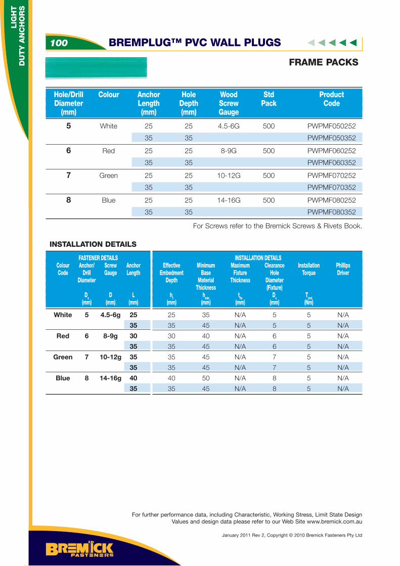
5 White 25 25 4.5-6G 500 PWPMF050252
35 35 PWPMF050352
6 Red 25 25 8-9G 500 PWPMF060252
35 35 PWPMF060352
7 Green 25 25 10-12G 500 PWPMF070252
35 35 PWPMF070352
8 Blue 25 25 14-16G 500 PWPMF080252
35 35 PWPMF080352
For Screws refer to the Bremick Screws & Rivets Book.
Hole/Drill Colour Anchor Hole Wood Std Product Diameter Length Depth Screw Pack Code (mm) (mm) (mm) Gauge
FRAME PACKS
White 5 4.5-6g 25
35
Red 6 8-9g 30
35
Green 7 10-12g 35
35
Blue 8 14-16g 40
35
FASTENER DETAILS Colour Anchor/ Screw Anchor Code Drill Gauge Length Diameter
Do D L (mm) (mm) (mm)
INSTALLATION DETAILS Effective Minimum Maximum Clearance Installation Phillips Embedment Base Fixture Hole Torque Driver Depth Material Thickness Diameter Thickness (Fixture) ht hmin tfi x Dc Tinst (mm) (mm) (mm) (mm) (Nm)
INSTALLATION DETAILS
25 35 N/A 5 5 N/A
35 45 N/A 5 5 N/A
30 40 N/A 6 5 N/A
35 45 N/A 6 5 N/A
35 45 N/A 7 5 N/A
35 45 N/A 7 5 N/A
40 50 N/A 8 5 N/A
35 45 N/A 8 5 N/A
BREMPLUG™ PVC WALL PLUGS100
LIG
HT
D
UT
Y A
NC
HO
RS
For further performance data, including Characteristic, Working Stress, Limit State Design Values and design data please refer to our Web Site www.bremick.com.au
January 2011 Rev 2, Copyright © 2010 Bremick Fasteners Pty Ltd
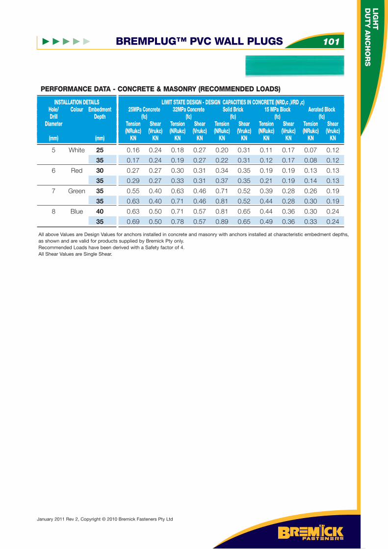
BREMPLUG™ PVC WALL PLUGS 101
LIG
HT
DU
TY
AN
CH
OR
S
January 2011 Rev 2, Copyright © 2010 Bremick Fasteners Pty Ltd
5 White 25
35
6 Red 30
35
7 Green 35
35
8 Blue 40
35
INSTALLATION DETAILS Hole/ Colour Embedment Drill Depth Diameter (mm) (mm)
LIMIT STATE DESIGN - DESIGN CAPACITIES IN CONCRETE (NRD,c ,VRD ,c) 25MPa Concrete 32MPa Concrete Solid Brick 15 MPa Block Aerated Block (fc) (fc) (fc) (fc) (fc) Tension Shear Tension Shear Tension Shear Tension Shear Tension Shear (NRukc) (Vrukc) (NRukc) (Vrukc) (NRukc) (Vrukc) (NRukc) (Vrukc) (NRukc) (Vrukc) KN KN KN KN KN KN KN KN KN KN
0.16 0.24 0.18 0.27 0.20 0.31 0.11 0.17 0.07 0.12
0.17 0.24 0.19 0.27 0.22 0.31 0.12 0.17 0.08 0.12
0.27 0.27 0.30 0.31 0.34 0.35 0.19 0.19 0.13 0.13
0.29 0.27 0.33 0.31 0.37 0.35 0.21 0.19 0.14 0.13
0.55 0.40 0.63 0.46 0.71 0.52 0.39 0.28 0.26 0.19
0.63 0.40 0.71 0.46 0.81 0.52 0.44 0.28 0.30 0.19
0.63 0.50 0.71 0.57 0.81 0.65 0.44 0.36 0.30 0.24
0.69 0.50 0.78 0.57 0.89 0.65 0.49 0.36 0.33 0.24
All above Values are Design Values for anchors installed in concrete and masonry with anchors installed at characteristic embedment depths, as shown and are valid for products supplied by Bremick Pty only.Recommended Loads have been derived with a Safety factor of 4.All Shear Values are Single Shear.
PERFORMANCE DATA - CONCRETE & MASONRY (RECOMMENDED LOADS)
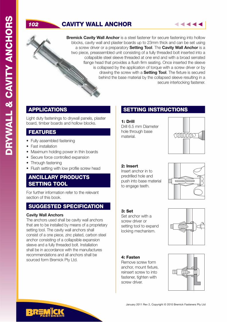
Bremick Cavity Wall Anchor is a steel fastener for secure fastening into hollow blocks, cavity wall and plaster boards up to 23mm thick and can be set using
a screw driver or a preparatory Setting Tool. The Cavity Wall Anchor is a two piece, preassembled unit consisting of a fully threaded bolt inserted into a
collapsible steel sleeve threaded at one end and with a broad serrated flange head that provides a flush firm seating. Once inserted the sleeve
is collapsed by the application of torque with a screw driver or by drawing the screw with a Setting Tool. The fixture is secured behind the base material by the collapsed sleeve resulting in a
secure interlocking fastener.
APPLICATIONS
Light duty fastenings to drywall panels, plaster board, timber boards and hollow blocks.
FEATURES
• Fully assembled fastening • Fast installation • Maximum holding power in thin boards • Secure force controlled expansion• Through fastening• Flush setting with low profile screw head
ANCILLARY PRODUCTSSETTING TOOL
For further information refer to the relevant section of this book.
SUGGESTED SPECIFICATION
Cavity Wall AnchorsThe anchors used shall be cavity wall anchors that are to be installed by means of a proprietary setting tool. The cavity wall anchors shall consist of a one piece, zinc plated, carbon steel anchor consisting of a collapsible expansion sleeve and a fully threaded bolt. Installation shall be in accordance with the manufactures recommendations and all anchors shall be sourced form Bremick Pty Ltd.
SETTING INSTRUCTIONS
1: DrillDrill 6.5 mm Diameterhole through base material.
2: InsertInsert anchor in topredrilled hole andpush into base materialto engage teeth.
3: SetSet anchor with ascrew driver or setting tool to expandlocking mechanism.
4: FastenRemove screw form anchor, mount fixture, reinsert screw to into fastener, tighten withscrew driver.
CAVITY WALL ANCHOR102
DR
YW
ALL &
CA
VIT
Y A
NC
HO
RS
January 2011 Rev 2, Copyright © 2010 Bremick Fasteners Pty Ltd
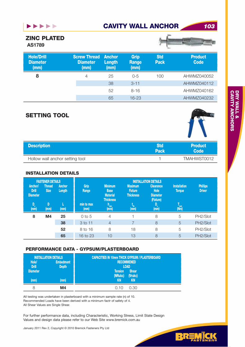
CAVITY WALL ANCHOR 103
DR
Y W
ALL &
C
AV
ITY
AN
CH
OR
S
For further performance data, including Characteristic, Working Stress, Limit State Design Values and design data please refer to our Web Site www.bremick.com.au
January 2011 Rev 2, Copyright © 2010 Bremick Fasteners Pty Ltd
8 4 25 0-5 100 AHWMZ040052
38 3-11 AHWMZ040112
52 8-16 AHWMZ040162
65 16-23 AHWMZ040232
Hole/Drill Screw Thread Anchor Grip Std Product Diameter Diameter Length Range Pack Code (mm) (mm) (mm) (mm)
ZINC PLATED AS1789
Hollow wall anchor setting tool 1 TMAHWST0012
Description Std Product Pack Code
SETTING TOOL
8 M4 25
38
52
65
FASTENER DETAILS Anchor/ Thread Anchor Drill Size Length Diameter
Do D L (mm) (mm) (mm)
INSTALLATION DETAILS Grip Minimum Maximum Clearance Installation Phillips Range Base Fixture Hole Torque Driver Material Thickness Diameter Thickness (Fixture) min to max hmin tfi x Dc Tinst (mm) (mm) (mm) (mm) (Nm)
INSTALLATION DETAILS
0 to 5 4 1 8 5 PH2/Slot
3 to 11 4 7 8 5 PH2/Slot
8 to 16 8 18 8 5 PH2/Slot
16 to 23 10 13 8 5 PH2/Slot
8 M4
INSTALLATION DETAILS Hole/ Embedment Drill Depth Diameter (mm) (mm)
CAPACITIES IN 10mm THICK GYPSUM / PLASTERBOARD RECOMMENED LOAD Tension Shear (NRukc) (Vrukc) KN KN
PERFORMANCE DATA - GYPSUM/PLASTERBOARD
0.10 0.30
All testing was undertaken in plasterboard with a minimum sample rate (n) of 10.Recommended Loads have been derived with a minimum factr of safety of 4.All Shear Values are Single Shear.
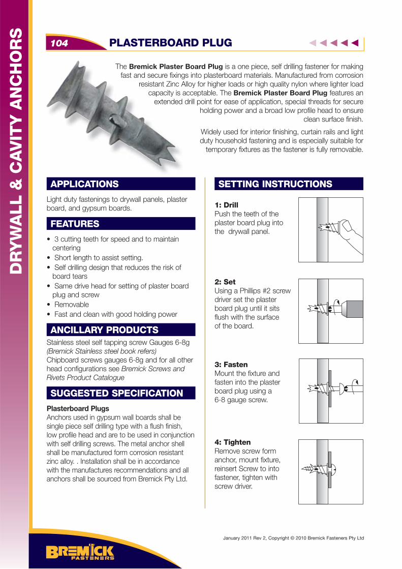
The Bremick Plaster Board Plug is a one piece, self drilling fastener for making fast and secure fixings into plasterboard materials. Manufactured from corrosion
resistant Zinc Alloy for higher loads or high quality nylon where lighter load capacity is acceptable. The Bremick Plaster Board Plug features an
extended drill point for ease of application, special threads for secure holding power and a broad low profile head to ensure
clean surface finish.
Widely used for interior finishing, curtain rails and light duty household fastening and is especially suitable for
temporary fixtures as the fastener is fully removable.
APPLICATIONS
Light duty fastenings to drywall panels, plaster board, and gypsum boards.
FEATURES
• 3 cutting teeth for speed and to maintain centering• Short length to assist setting.• Self drilling design that reduces the risk of board tears • Same drive head for setting of plaster board plug and screw• Removable• Fast and clean with good holding power
ANCILLARY PRODUCTSStainless steel self tapping screw Gauges 6-8g(Bremick Stainless steel book refers)Chipboard screws gauges 6-8g and for all other head configurations see Bremick Screws and Rivets Product Catalogue
SUGGESTED SPECIFICATION
Plasterboard PlugsAnchors used in gypsum wall boards shall be single piece self drilling type with a flush finish, low profile head and are to be used in conjunction with self drilling screws. The metal anchor shell shall be manufactured form corrosion resistant zinc alloy. . Installation shall be in accordance with the manufactures recommendations and all anchors shall be sourced from Bremick Pty Ltd.
SETTING INSTRUCTIONS
1: DrillPush the teeth of the plaster board plug into the drywall panel.
2: Set Using a Phillips #2 screw driver set the plaster board plug until it sits flush with the surface of the board.
3: FastenMount the fixture and fasten into the plaster board plug using a 6-8 gauge screw.
4: TightenRemove screw form anchor, mount fixture, reinsert Screw to into fastener, tighten withscrew driver.
The Bremick Plaster fast and secure fixing
resistant Zinc Acapacity is a
extended
PLASTERBOARD PLUG104
DR
YW
ALL &
CA
VIT
Y A
NC
HO
RS
January 2011 Rev 2, Copyright © 2010 Bremick Fasteners Pty Ltd
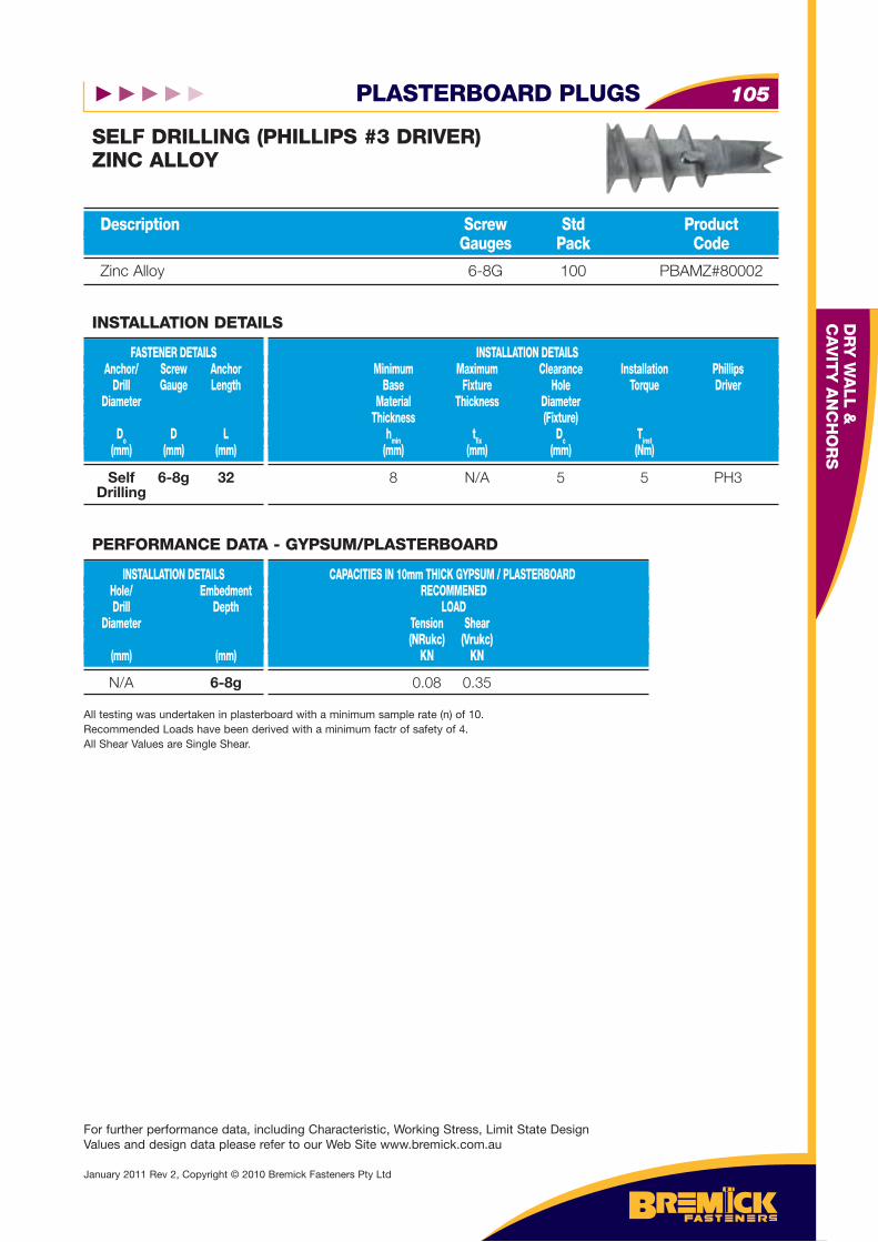
PLASTERBOARD PLUGS 105
DR
Y W
ALL &
C
AV
ITY
AN
CH
OR
S
For further performance data, including Characteristic, Working Stress, Limit State Design Values and design data please refer to our Web Site www.bremick.com.au
January 2011 Rev 2, Copyright © 2010 Bremick Fasteners Pty Ltd
Zinc Alloy 6-8G 100 PBAMZ#80002
Description Screw Std Product Gauges Pack Code
SELF DRILLING (PHILLIPS #3 DRIVER)ZINC ALLOY
Self 6-8g 32 Drilling
FASTENER DETAILS Anchor/ Screw Anchor Drill Gauge Length Diameter
Do D L (mm) (mm) (mm)
INSTALLATION DETAILS Minimum Maximum Clearance Installation Phillips Base Fixture Hole Torque Driver Material Thickness Diameter Thickness (Fixture) hmin tfi x Dc Tinst (mm) (mm) (mm) (Nm)
INSTALLATION DETAILS
8 N/A 5 5 PH3
N/A 6-8g
INSTALLATION DETAILS Hole/ Embedment Drill Depth Diameter (mm) (mm)
CAPACITIES IN 10mm THICK GYPSUM / PLASTERBOARD RECOMMENED LOAD Tension Shear (NRukc) (Vrukc) KN KN
PERFORMANCE DATA - GYPSUM/PLASTERBOARD
0.08 0.35
All testing was undertaken in plasterboard with a minimum sample rate (n) of 10.Recommended Loads have been derived with a minimum factr of safety of 4.All Shear Values are Single Shear.

Bremtoggle™ Gravity Toggles are pre assembled fasteners consisting of a fully threaded screw, steel retaining nut and a hinged pressed steel toggle bar. Fastening is achieved by passing the hinged toggle bar through the drilled
hole and once inserted the toggle bar rotates parallel to the far face of the base material and tightening of the screw draws the
toggle up resulting in a broad, positive interlock to the back face of the base material.
APPLICATIONS
Light duty fastenings to drywall panels, plaster board, timber boards and hollow blocks.
FEATURES
• Fully assembled fastening • Fast installation • Maximum holding power in thin boards • Secure interlocking fastening• Fully removable• Fire resistant
SUGGESTED SPECIFICATION
Bremtoggle Gravity Toggle AnchorsThe anchors used shall be preassembled gravity toggle anchors consisting of a carbon steel toggle hinged onto a carbon steel zinc plated screw. Installation shall be in accordance with the manufactures recommendations and all anchors shall be sourced form Bremick Pty Ltd.
SETTING INSTRUCTIONS
1: DrillDrill hole through base material to specifieddiameter.
2: InsertRemove screw and pass through fixture. Reinstall screw into toggle and insert toggle through hole in base material.
3: SetAllow toggle to fall into place and tighten with a screw driver untilspecified torque isachieved.
Bremtoggle™ Gravithreaded screFastening is a
far face
BREMTOGGLE™ GRAVITY TOGGLE106
DR
YW
ALL &
CA
VIT
Y A
NC
HO
RS
January 2011 Rev 2, Copyright © 2010 Bremick Fasteners Pty Ltd
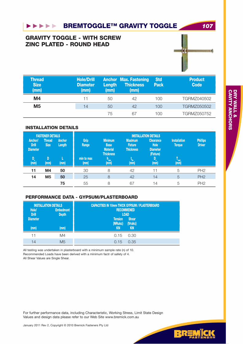
BREMTOGGLE™ GRAVITY TOGGLE 107
DR
Y W
ALL &
C
AV
ITY
AN
CH
OR
S
For further performance data, including Characteristic, Working Stress, Limit State Design Values and design data please refer to our Web Site www.bremick.com.au
January 2011 Rev 2, Copyright © 2010 Bremick Fasteners Pty Ltd
M4 11 50 42 100 TGRMZ040502
M5 14 50 42 100 TGRMZ050502
75 67 100 TGRMZ050752
Thread Hole/Drill Anchor Max. Fastening Std Product Size Diameter Length Thickness Pack Code (mm) (mm) (mm) (mm)
GRAVITY TOGGLE - WITH SCREWZINC PLATED - ROUND HEAD
11 M4 50
14 M5 50
75
FASTENER DETAILS Anchor/ Thread Anchor Drill Size Length Diameter
Do D L (mm) (mm) (mm)
INSTALLATION DETAILS Grip Minimum Maximum Clearance Installation Phillips Range Base Fixture Hole Torque Driver Material Thickness Diameter Thickness (Fixture) min to max hmin tfi x Dc Tinst (mm) (mm) (mm) (mm) (mm)
INSTALLATION DETAILS
30 8 42 11 5 PH2
25 8 42 14 5 PH2
55 8 67 14 5 PH2
11 M4
14 M5
INSTALLATION DETAILS Hole/ Embedment Drill Depth Diameter (mm) (mm)
CAPACITIES IN 10mm THICK GYPSUM / PLASTERBOARD RECOMMENED LOAD Tension Shear (NRukc) (Vrukc) KN KN
PERFORMANCE DATA - GYPSUM/PLASTERBOARD
0.15 0.30
0.15 0.35
All testing was undertaken in plasterboard with a minimum sample rate (n) of 10.Recommended Loads have been derived with a minimum factr of safety of 4.All Shear Values are Single Shear.
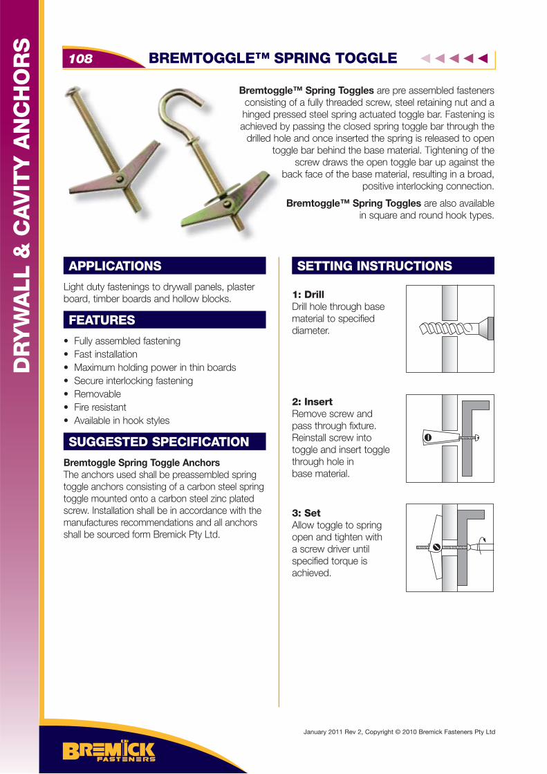
Bremtoggle™ Spring Toggles are pre assembled fasteners consisting of a fully threaded screw, steel retaining nut and a hinged pressed steel spring actuated toggle bar. Fastening is achieved by passing the closed spring toggle bar through the
drilled hole and once inserted the spring is released to open toggle bar behind the base material. Tightening of the
screw draws the open toggle bar up against the back face of the base material, resulting in a broad,
positive interlocking connection.
Bremtoggle™ Spring Toggles are also available in square and round hook types.
APPLICATIONS
Light duty fastenings to drywall panels, plaster board, timber boards and hollow blocks.
FEATURES
• Fully assembled fastening • Fast installation • Maximum holding power in thin boards • Secure interlocking fastening• Removable• Fire resistant• Available in hook styles
SUGGESTED SPECIFICATION
Bremtoggle Spring Toggle AnchorsThe anchors used shall be preassembled spring toggle anchors consisting of a carbon steel spring toggle mounted onto a carbon steel zinc plated screw. Installation shall be in accordance with the manufactures recommendations and all anchors shall be sourced form Bremick Pty Ltd.
SETTING INSTRUCTIONS
1: DrillDrill hole through base material to specifieddiameter.
2: InsertRemove screw and pass through fixture. Reinstall screw into toggle and insert toggle through hole in base material.
3: SetAllow toggle to spring open and tighten with a screw driver untilspecified torque isachieved.
Bremtoggconsistinghinged prachieved b
drilled hotog
BREMTOGGLE™ SPRING TOGGLE108
DR
YW
ALL &
CA
VIT
Y A
NC
HO
RS
January 2011 Rev 2, Copyright © 2010 Bremick Fasteners Pty Ltd
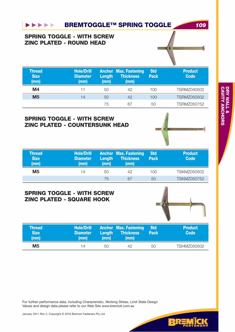
BREMTOGGLE™ SPRING TOGGLE 109
DR
Y W
ALL &
C
AV
ITY
AN
CH
OR
S
For further performance data, including Characteristic, Working Stress, Limit State Design Values and design data please refer to our Web Site www.bremick.com.au
January 2011 Rev 2, Copyright © 2010 Bremick Fasteners Pty Ltd
M5 14 50 42 50 TSHMZ050502
Thread Hole/Drill Anchor Max. Fastening Std Product Size Diameter Length Thickness Pack Code (mm) (mm) (mm) (mm)
SPRING TOGGLE - WITH SCREWZINC PLATED - SQUARE HOOK
M4 11 50 42 100 TSRMZ040502
M5 14 50 42 100 TSRMZ050502
75 67 50 TSRMZ050752
Thread Hole/Drill Anchor Max. Fastening Std Product Size Diameter Length Thickness Pack Code (mm) (mm) (mm) (mm)
SPRING TOGGLE - WITH SCREWZINC PLATED - ROUND HEAD
M5 14 50 42 100 TSKMZ050502
75 67 50 TSKMZ050752
Thread Hole/Drill Anchor Max. Fastening Std Product Size Diameter Length Thickness Pack Code (mm) (mm) (mm) (mm)
SPRING TOGGLE - WITH SCREWZINC PLATED - COUNTERSUNK HEAD
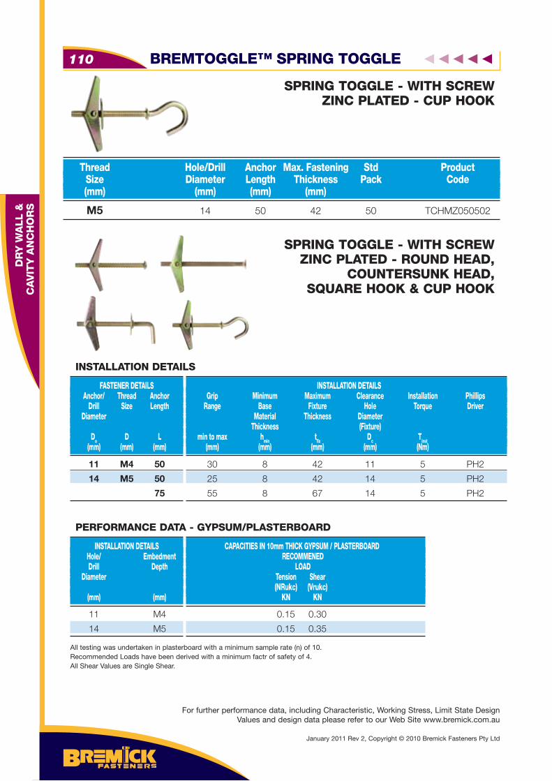
BREMTOGGLE™ SPRING TOGGLE110
DR
Y W
ALL &
C
AV
ITY
AN
CH
OR
S M5 14 50 42 50 TCHMZ050502
Thread Hole/Drill Anchor Max. Fastening Std Product Size Diameter Length Thickness Pack Code (mm) (mm) (mm) (mm)
SPRING TOGGLE - WITH SCREWZINC PLATED - CUP HOOK
SPRING TOGGLE - WITH SCREWZINC PLATED - ROUND HEAD,
COUNTERSUNK HEAD, SQUARE HOOK & CUP HOOK
11 M4 50
14 M5 50
75
FASTENER DETAILS Anchor/ Thread Anchor Drill Size Length Diameter
Do D L (mm) (mm) (mm)
INSTALLATION DETAILS Grip Minimum Maximum Clearance Installation Phillips Range Base Fixture Hole Torque Driver Material Thickness Diameter Thickness (Fixture) min to max hmin tfi x Dc Tinst (mm) (mm) (mm) (mm) (Nm)
INSTALLATION DETAILS
30 8 42 11 5 PH2
25 8 42 14 5 PH2
55 8 67 14 5 PH2
11 M4
14 M5
INSTALLATION DETAILS Hole/ Embedment Drill Depth Diameter (mm) (mm)
CAPACITIES IN 10mm THICK GYPSUM / PLASTERBOARD RECOMMENED LOAD Tension Shear (NRukc) (Vrukc) KN KN
PERFORMANCE DATA - GYPSUM/PLASTERBOARD
0.15 0.30
0.15 0.35
All testing was undertaken in plasterboard with a minimum sample rate (n) of 10.Recommended Loads have been derived with a minimum factr of safety of 4.All Shear Values are Single Shear.
January 2011 Rev 2, Copyright © 2010 Bremick Fasteners Pty Ltd
For further performance data, including Characteristic, Working Stress, Limit State Design Values and design data please refer to our Web Site www.bremick.com.au
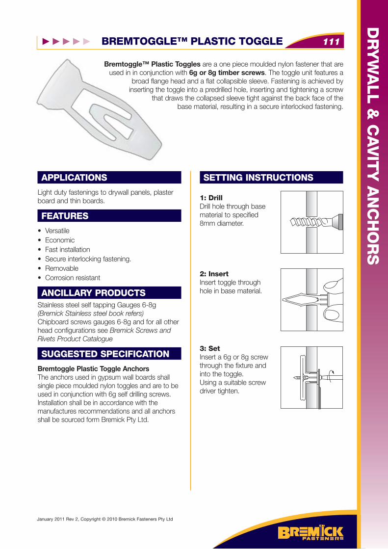
BREMTOGGLE™ PLASTIC TOGGLE 111
DR
YW
ALL &
CA
VIT
Y A
NC
HO
RS
January 2011 Rev 2, Copyright © 2010 Bremick Fasteners Pty Ltd
Bremtoggle™ Plastic Toggles are a one piece moulded nylon fastener that are used in in conjunction with 6g or 8g timber screws. The toggle unit features a
broad flange head and a flat collapsible sleeve. Fastening is achieved by inserting the toggle into a predrilled hole, inserting and tightening a screw
that draws the collapsed sleeve tight against the back face of the base material, resulting in a secure interlocked fastening.
APPLICATIONS
Light duty fastenings to drywall panels, plaster board and thin boards.
FEATURES
• Versatile• Economic• Fast installation• Secure interlocking fastening.• Removable• Corrosion resistant
ANCILLARY PRODUCTSStainless steel self tapping Gauges 6-8g(Bremick Stainless steel book refers)Chipboard screws gauges 6-8g and for all other head configurations see Bremick Screws and Rivets Product Catalogue
SUGGESTED SPECIFICATION
Bremtoggle Plastic Toggle AnchorsThe anchors used in gypsum wall boards shall single piece moulded nylon toggles and are to be used in conjunction with 6g self drilling screws. Installation shall be in accordance with the manufactures recommendations and all anchors shall be sourced form Bremick Pty Ltd.
SETTING INSTRUCTIONS
1: DrillDrill hole through base material to specified8mm diameter.
2: InsertInsert toggle through hole in base material.
3: SetInsert a 6g or 8g screw through the fixture and into the toggle. Using a suitable screw driver tighten.
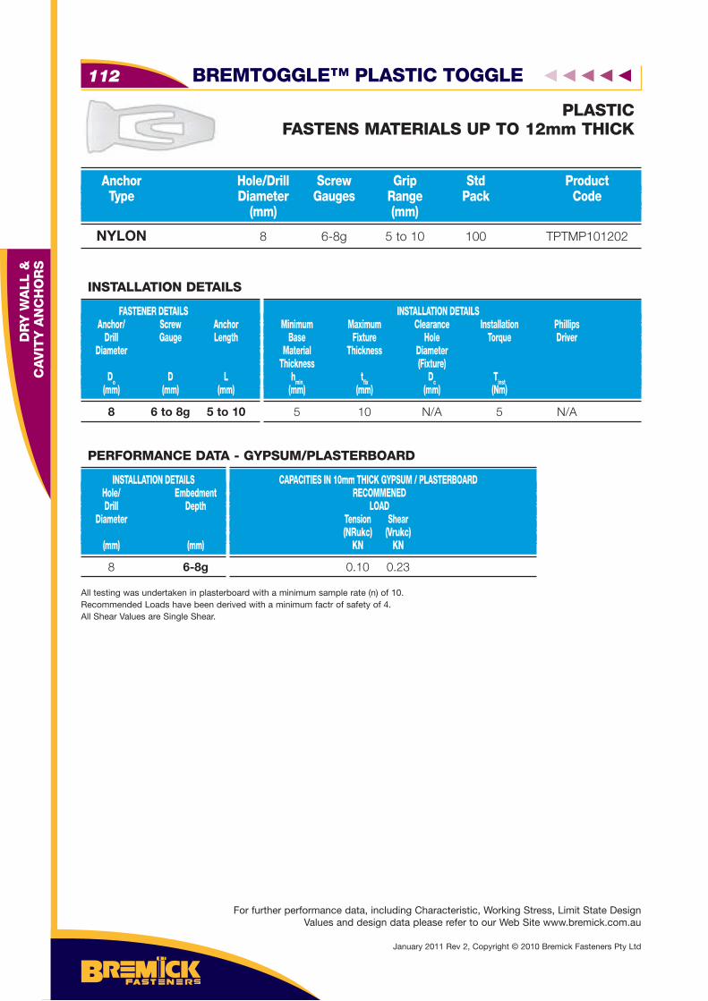
NYLON 8 6-8g 5 to 10 100 TPTMP101202
Anchor Hole/Drill Screw Grip Std Product Type Diameter Gauges Range Pack Code (mm) (mm)
PLASTICFASTENS MATERIALS UP TO 12mm THICK
8 6 to 8g 5 to 10
FASTENER DETAILS Anchor/ Screw Anchor Drill Gauge Length Diameter
Do D L (mm) (mm) (mm)
INSTALLATION DETAILS Minimum Maximum Clearance Installation Phillips Base Fixture Hole Torque Driver Material Thickness Diameter Thickness (Fixture) hmin tfi x Dc Tinst (mm) (mm) (mm) (Nm)
INSTALLATION DETAILS
5 10 N/A 5 N/A
8 6-8g
INSTALLATION DETAILS Hole/ Embedment Drill Depth Diameter (mm) (mm)
CAPACITIES IN 10mm THICK GYPSUM / PLASTERBOARD RECOMMENED LOAD Tension Shear (NRukc) (Vrukc) KN KN
PERFORMANCE DATA - GYPSUM/PLASTERBOARD
0.10 0.23
All testing was undertaken in plasterboard with a minimum sample rate (n) of 10.Recommended Loads have been derived with a minimum factr of safety of 4.All Shear Values are Single Shear.
BREMTOGGLE™ PLASTIC TOGGLE112
DR
Y W
ALL &
C
AV
ITY
AN
CH
OR
S
January 2011 Rev 2, Copyright © 2010 Bremick Fasteners Pty Ltd
For further performance data, including Characteristic, Working Stress, Limit State Design Values and design data please refer to our Web Site www.bremick.com.au
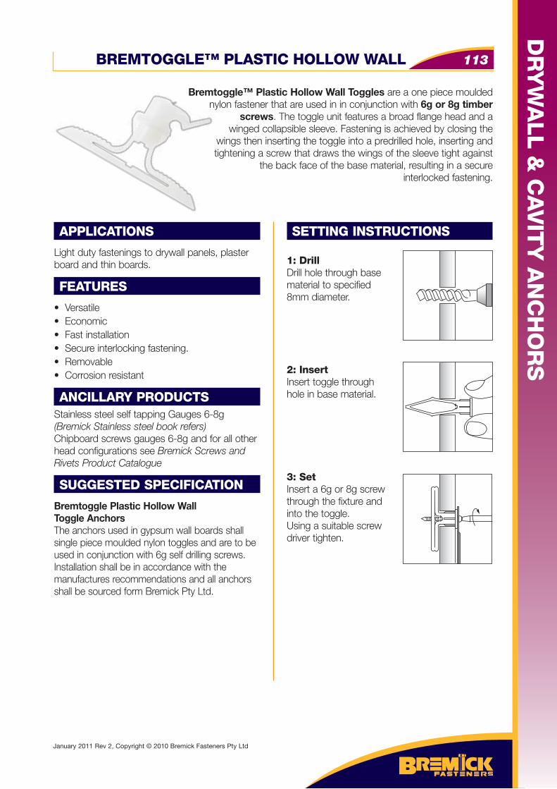
BREMTOGGLE™ PLASTIC HOLLOW WALL 113
DR
YW
ALL &
CA
VIT
Y A
NC
HO
RS
January 2011 Rev 2, Copyright © 2010 Bremick Fasteners Pty Ltd
APPLICATIONS
Light duty fastenings to drywall panels, plaster board and thin boards.
FEATURES
• Versatile• Economic• Fast installation• Secure interlocking fastening.• Removable• Corrosion resistant
ANCILLARY PRODUCTSStainless steel self tapping Gauges 6-8g(Bremick Stainless steel book refers)Chipboard screws gauges 6-8g and for all other head configurations see Bremick Screws and Rivets Product Catalogue
SUGGESTED SPECIFICATION
Bremtoggle Plastic Hollow Wall Toggle AnchorsThe anchors used in gypsum wall boards shall single piece moulded nylon toggles and are to be used in conjunction with 6g self drilling screws. Installation shall be in accordance with the manufactures recommendations and all anchors shall be sourced form Bremick Pty Ltd.
SETTING INSTRUCTIONS
1: DrillDrill hole through base material to specified8mm diameter.
2: InsertInsert toggle through hole in base material.
3: SetInsert a 6g or 8g screw through the fixture and into the toggle. Using a suitable screw driver tighten.
Bremtoggle™ Plastic Hollow Wall Toggles are a one piece moulded nylon fastener that are used in in conjunction with 6g or 8g timber
screws. The toggle unit features a broad flange head and a winged collapsible sleeve. Fastening is achieved by closing the
wings then inserting the toggle into a predrilled hole, inserting and tightening a screw that draws the wings of the sleeve tight against
the back face of the base material, resulting in a secure interlocked fastening.
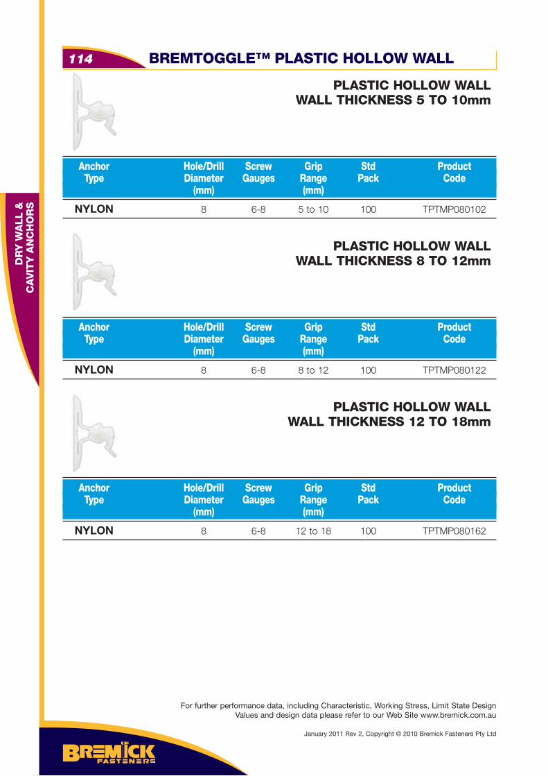
NYLON 8 6-8 5 to 10 100 TPTMP080102
Anchor Hole/Drill Screw Grip Std Product Type Diameter Gauges Range Pack Code (mm) (mm)
PLASTIC HOLLOW WALLWALL THICKNESS 5 TO 10mm
NYLON 8 6-8 8 to 12 100 TPTMP080122
Anchor Hole/Drill Screw Grip Std Product Type Diameter Gauges Range Pack Code (mm) (mm)
PLASTIC HOLLOW WALLWALL THICKNESS 8 TO 12mm
NYLON 8 6-8 12 to 18 100 TPTMP080162
Anchor Hole/Drill Screw Grip Std Product Type Diameter Gauges Range Pack Code (mm) (mm)
PLASTIC HOLLOW WALLWALL THICKNESS 12 TO 18mm
BREMTOGGLE™ PLASTIC HOLLOW WALL114
DR
Y W
ALL &
C
AV
ITY
AN
CH
OR
S
January 2011 Rev 2, Copyright © 2010 Bremick Fasteners Pty Ltd
For further performance data, including Characteristic, Working Stress, Limit State Design Values and design data please refer to our Web Site www.bremick.com.au
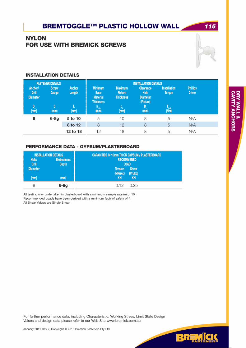
BREMTOGGLE™ PLASTIC HOLLOW WALL 115
DR
Y W
ALL &
C
AV
ITY
AN
CH
OR
S
January 2011 Rev 2, Copyright © 2010 Bremick Fasteners Pty Ltd
For further performance data, including Characteristic, Working Stress, Limit State Design Values and design data please refer to our Web Site www.bremick.com.au
NYLONFOR USE WITH BREMICK SCREWS
8 6-8g 5 to 10
8 to 12
12 to 18
FASTENER DETAILS Anchor/ Screw Anchor Drill Gauge Length Diameter
Do D L (mm) (mm) (mm)
INSTALLATION DETAILS Minimum Maximum Clearance Installation Phillips Base Fixture Hole Torque Driver Material Thickness Diameter Thickness (Fixture) hmin tfi x Dc Tinst (mm) (mm) (mm) (Nm)
INSTALLATION DETAILS
5 10 8 5 N/A
8 12 8 5 N/A
12 18 8 5 N/A
8 6-8g
INSTALLATION DETAILS Hole/ Embedment Drill Depth Diameter (mm) (mm)
CAPACITIES IN 10mm THICK GYPSUM / PLASTERBOARD RECOMMENED LOAD Tension Shear (NRukc) (Vrukc) KN KN
PERFORMANCE DATA - GYPSUM/PLASTERBOARD
0.12 0.25
All testing was undertaken in plasterboard with a minimum sample rate (n) of 10.Recommended Loads have been derived with a minimum factr of safety of 4.All Shear Values are Single Shear.
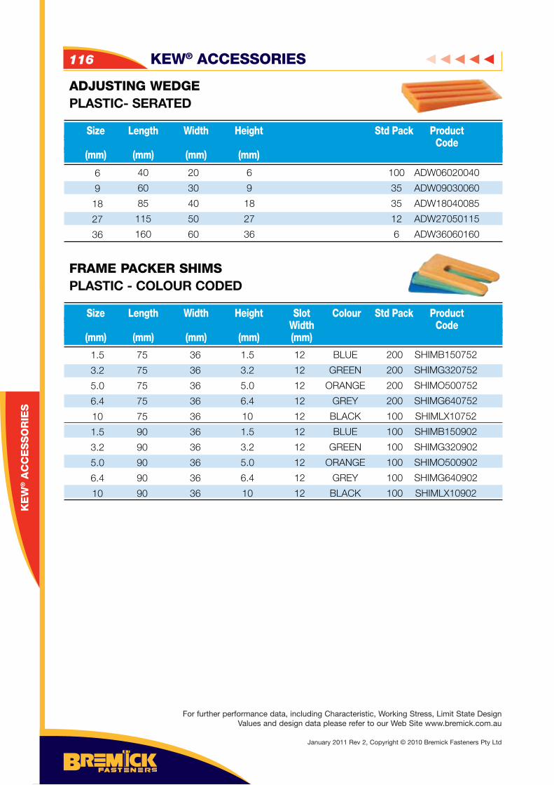
ADJUSTING WEDGEPLASTIC- SERATED
FRAME PACKER SHIMSPLASTIC - COLOUR CODED
Size Length Width Height Std Pack Product Code (mm) (mm) (mm) (mm)
Size Length Width Height Slot Colour Std Pack Product Width Code (mm) (mm) (mm) (mm) (mm)
6
9
18
27
36
1.5
3.2
5.0
6.4
10
1.5
3.2
5.0
6.4
10
75
75
75
75
75
90
90
90
90
90
36
36
36
36
36
36
36
36
36
36
1.5
3.2
5.0
6.4
10
1.5
3.2
5.0
6.4
10
12
12
12
12
12
12
12
12
12
12
BLUE
GREEN
ORANGE
GREY
BLACK
BLUE
GREEN
ORANGE
GREY
BLACK
200
200
200
200
100
100
100
100
100
100
SHIMB150752
SHIMG320752
SHIMO500752
SHIMG640752
SHIMLX10752
SHIMB150902
SHIMG320902
SHIMO500902
SHIMG640902
SHIMLX10902
20
30
40
50
60
6
9
18
27
36
100
35
35
12
6
ADW06020040
ADW09030060
ADW18040085
ADW27050115
ADW36060160
40
60
85
115
160
KEW® ACCESSORIES116
KE
W® A
CC
ES
SO
RIE
S
For further performance data, including Characteristic, Working Stress, Limit State Design Values and design data please refer to our Web Site www.bremick.com.au
January 2011 Rev 2, Copyright © 2010 Bremick Fasteners Pty Ltd