Maryland General Hospital - Pennsylvania State University · Technical Assignment 1 ... Asbestos...
27
CPEP Website: http://www.engr.psu.edu/ae/thesis/portfolios/2009/bwg5000 Maryland General Hospital Central Care Expansion Baltimore, MD Brian Goodykoontz Graphics courtesy of hord|coplan|macht Graphics courtesy of hord|coplan|macht Sponsored by: Construction Management Option Technical Assignment 1 September 29th 2008
Transcript of Maryland General Hospital - Pennsylvania State University · Technical Assignment 1 ... Asbestos...

CPEP Website: http://www.engr.psu.edu/ae/thesis/portfolios/2009/bwg5000
Maryland General HospitalCentral Care Expansion
Baltimore, MD
Brian GoodykoontzGraphics courtesy of hord|coplan|macht
Graphics courtesy of hord|coplan|macht
Sponsored by: Construction Management Option
Technical Assignment 1September 29th 2008

Page 0 of 20
TABLE OF CONTENTS
Executive Summary ………………………………………………………………………………………………… 1 Project Schedule Summary …………………………………………………………………………………….. 2 Building Systems Summary …………………………………………………………………………………….. 4 Project Cost Evaluation…………………………………………………………………………………………… 6 Existing Conditions ………………………………………………………………………………………………… 8 Local Conditions …………………………………………………………………………………………………….. 10 Client Information ………………………………………………………………………………………………….. 11 Project Delivery System …………………………………………………………………………………………. 12 Staffing Plan …………………………………………………………………………………………………………… 14 Appendix A: Project Schedule Summary …………………………………………………………………. 16 Appendix B: D4 Cost Estimate ……………….……………………………………………………………….. 17 Appendix C: RS Means 2008 Square Foot Costs……………………………………………………… 18 Appendix D: Existing Conditions Site Plan ....…………………………………………………………… 19

Page 1 of 20
EXECUTIVE SUMMARY
This technical assignment provides an introduction to the existing conditions of the Maryland General Hospital Central Care Expansion project, and the construction management techniques employed by the Barton Malow Company to successfully deliver the project. This report will present and analyze the project summary schedule, the building systems, project cost, existing conditions, local conditions, project delivery system, and the project staffing plan.
The project is a $57 million dollar addition and partial renovation to Maryland General Hospital located in Baltimore, MD. Barton Malow Company was hired by the owner of Maryland General, University of Maryland Medical System, to act as the construction manager at risk on the project. Hord Coplan Macht is the project architect hired by the University of Maryland. This project is quite unique because the phasing of the project requires the upper floors of the building to be enclosed and fit‐out prior to the excavation of the basement, completion of the floor systems, and fit‐out of the first three floors in the courtyard. The project has been staffed with a team who has strong working relationships and was strong with structural steel experience to work through some of the more complex portions of the project.

Page 2 of 20
PROJECT SCHEDULE SUMMARY
Please see Appendix A for Project Schedule Summary
The project was broken into two phases with the structure, third floor pharmacy, and upper floors being completed in the first phase and the basement through partial third floor in the second phase.
Foundation Sequence
Since the basement of the courtyard infill will not be excavated until the second phase, the caissons were drilled from existing grade level through the area which will be the future basement until they hit their designed depth on rock 65 feet down. Several new spread footings were hand dug at the bottom of existing areaways to the basement in the courtyard. The new spread footings and reinforced footings in the existing building also had be hand dug, in some places up to 16 feet.
The foundation work started with the reinforcing of the existing and new spread footings in the existing building. This process lasted several months, spanning the duration of caisson work in the courtyard. Once the caissons were completed in the courtyard remaining spread footings in the areaways could then be completed.
Caisson Being Drilled Caisson Excavation support
Structural Sequence
The new structural steel could not be set on top of the existing structure until all the columns and footings below had been reinforced. This process of reinforcing the columns and footings required selective demolition of existing walls, removal of any existing fireproofing, and the rerouting of any electric, telecommunication, plumbing, ductwork which were in the way of the column plating. To accommodate the hospital’s needs during the construction, rooms in which columns needed to be reinforced could only be taken a few at a time.

Page 3 of 20
Structural Steel Progress Photos: 9/5/08, 9/15/08, 9/23/08
Knowing this the structural steel was erected starting in the courtyard to allow the reinforcement in the existing building to be completed. The steel worked up five stories in the courtyard, then across the existing building, and finally back to complete courtyard steel.
Finish Sequence
Once the structure has been completed, a temporary enclosure will be constructed so that the interior work can begin as the permanent enclosure is being installed. Additionally, on each floor there will be selective demolition that will need to occur to tie the new building to the old prior to the completion of the finish sequence. For phase one the finishes will start on the third floor over the existing building and work up through the fourth and fifth floors. If phase two is approved, trades will similarly move from the basement up to the third floor in the courtyard.
Before the finish work can begin the MEP risers and over head rough‐ins will be completed. The MEP and fire protection on the project was coordinated through weekly coordination meetings for several months leading up to the work. This process utilized a three dimensional model to produce the two dimensional coordinated drawings.
Once the major overhead MEP work has been completed the finish sequence will be: - Metal Studs - MEP Rough‐in - Gypsum Board - Painting - Electric/Lighting/Telecom Wire Pulls - Ceiling Grid - Ceramic Tile - Diffuser/Electrical Fixtures/Fire Protection Drops to Grid - Casework - Finish Paint - Flooring - Ceiling Tile - Doors & Hardware

Page 4 of 20
BUILDING SYSTEMS SUMMARY
Work Scope Yes/No Demolition Yes Support of Excavation Yes Structural Steel Yes Cast in Place Concrete Yes Precast Concrete No Mechanical System Yes Electrical System Yes Masonry Yes Curtainwall Yes
Demolition Selective Demolition was required for numerous portions of the project including:
- Room Reconfigurations - Column Reinforcement - New/Addition Attachment - Pockets for Steel
Asbestos abetment was necessary in the basement where there was asbestos flooring, and in several of the renovation and column reinforcing areas where pipes were being removed or relocated but had asbestos insulation. Excavation
- Six foot diameter corrugated steel tube was used to as excavation support for the caissons. This support is permanent until phase two when it will get demolished as the excavation proceeds.
- Piles and lagging will be used for the excavation of the basement during phase two.
Structural Steel - Wide flange beams and columns ‐ ASTM A 36A/36M - A 3 ¼” 3000 psi composite concrete slab on metal deck was use for each floor. - Four new braced frames were installed to accept any increased lateral loads on the building. - A 120 ton truck crane was utilized in two locations on the site to set all the members. The crane
started in the south setting the courtyard steel and then moved.

Page 5 of 20
Cast in Place Concrete
- A 3000 psi reinforced concrete was utilized for the caissons. - A 3000 psi reinforced concrete utilized for the new and replacement footings in the basement.
No formwork was necessary for theses footings as the holes were only slightly larger than the required footings.
- 4000 psi concrete was used stick built and modular formwork systems were utilized for the new footings at the courtyard perimeter and the two pilasters along the west wall of the courtyard.
- A 3 ¼” 3000 psi composite concrete slab with welded wire fabric on metal deck was use for each floor slab.
Mechanical System
- Two replacement 650 ton, 1950GPM cooling towers and two replacement 650 ton, 1293 GPM chillers were installed on the roof of the existing seven story building to east of the addition with a truck crane.
- Additionally, two new 380 ton air handling units located in the sixth floor penthouse will supply VAV boxes in the addition with constant air temperature which will then be heated to the appropriate supply temperature and supplied as need to rooms in the addition.
- The addition will utilize a wet type fire suppression system which will be tied into the existing hospital’s system.
Electrical System
- A 2000A 480/277 Volt 3‐phase electrical service will be provided to the hospital from an existing unit substation in the hospital.
- The hospital has an existing generator which will feed the emergency service for this expansion.
Masonry - The majority of the façade consists of a field brick with accent brick and stone on a metal stud
back up. Working from the outside in the system consists of brick/stone, air space, tyveck building wrap, denzglass board, metal studs and insulation, then interior gypsum board. This veneer façade will be installed with the use of a climbing scaffold on the west side of the building. On the north and partial east side of the standard scaffolding will be utilized on top of the existing roof to install the façade.
Curtainwall - A glass curtainwall will be utilized at the south stairwell and the first through the third floors at
the courtyard. This system will include a low‐ e coated, insulated glass with spandrel panels and be supported by mullions.
Conveying Systems
- For phase one the elevator will only service the fourth through the sixth floor. To accommodate this a suspended elevator pit will be utilized so that the elevator can become operational prior to the completion of phase two.

Page 6 of 20
PROJECT COST EVALUATION
Please see Appendix B for D4 Cost Estimate
Cost Summary
Maryland General Hospital: Costs Cost Cost/SF Construction Cost $31,942,172 $330.89Building Cost $33,044,379 $342.31Total Project Cost $57,000,000 $590.47*Construction Cost excludes sitework and permits Building Systems Cost
Maryland General Hospital: Building System Costs Building System Cost Cost/SF Structure $2,801,220 $29.02HVAC/Plumbing $7,768,195 $80.47Electrical $4,576,400 $47.41Fire Protection $349,000 $3.62Conveying System $890,487 $9.22
D4 Cost Estimate:
Historical Data Projects Project Name Size (SF) # of Floors Cost
Mississippi Baptist Health System 87,138 4 $11,672,790Good Samaritan Medical Center 106,943 6 $11,816,795 Using the D4 program I prepared an estimate for Maryland General Hospital based on the above historical data projects. These projects were selected based on their similarity of occupant use, and to cover a range of size and number of floors which covered that of this project. Using the averaging wizard and adjusting for time and location the D4 estimate came out to be $22,414,361 or $232.2/SF This estimate was about $9.5 million less than budgeted cost for Maryland General.

Page 7 of 20
RS Means
Building Attributes Perimeter (ft) *4th Floor 594.5 Total Area (SF) 96534 Basement Area(SF) 6200 I selected to use the 4‐8 story hospital in the 2008 RS Means book. Since the area of the building was below the range of the areas and there was no way to interpolate for the area I assumed that the smallest area of 100,000. Additionally, since RS Means did not have Face Brick on a metal stud backup for Hospitals, I assumed for the proposes of this estimate that the exterior wall was face brick with structural facing tile.
RS Means Calculations
Base Cost per SF 252.95 Per UnitAdjust Notes
Perimeter Adjust 0 4.15 per 100 lf Story Adjust 2.5 1.85 per 1 ft Basement 2.01 31.25 per sf basement Subtotal 257.46 Location Adjust 0.9 Baltimore, MD Total CC/SF 231.714 *Note basement addition was normalized for cost per the total square feet of the building. Comparison Both the D4 and RS Means Estimates were over $100/sf less than the actual construction cost of Maryland General Hospital. There are several factors that I believe contributed to the lard discrepancy among the estimates:
- The extensive and tedious column reinforcing to prepare the existing structure for the added load requires a lot of extra time and money but does not add to the square footage of the building.
- ICRA procedures that had to be followed due to these reinforcing sequences and room reconfigurations which would not typically be necessary for a new construction project such as the ones in the estimating tools.
- Phasing requirements such as added enclosure and concrete encased columns in the courtyard which will be demoed as part of phase two add scope to the project are not taken into accounted.

Page 8 of 20
SITE PLAN OF EXISTING CONDITIONS
Please see Appendix C for Existing Conditions Site Plan
Site Location - The site is located in downtown Baltimore, MD. - Bounded on all sides by streets:
o Martin Luther King, Jr Boulevard and Armory St. to the North. o Linden Avenue to the west. o Howard Road to the east of the existing hosptial
Neighboring Structures
- Two administration buildings (4 and 6 stories), parking garage (4 stories), and parking lot across Linden Ave from the site.
- Parking garage (6 stories) attached to the south end of the hospital. - Brownstone houses (varying in heights), many with little restaurants on the ground floor across
Howard St. from the site. - Light Rail on Howard Street. - Complex interchange among Martin Luther King Jr. Boulevard, Howard Street, and W. Chase
Street to North of the site.
Utility Relocation - Fiber optics feed going through courtyard into the hospital had to be relocated. - Trench drains in the hospital were left in during phase 1 to provide drainage but will have to be
removed during excavation in phase two. - Water and electric lines in the courtyard will also have to be relocated prior to excavation in
phase two.
Page 9 of 20
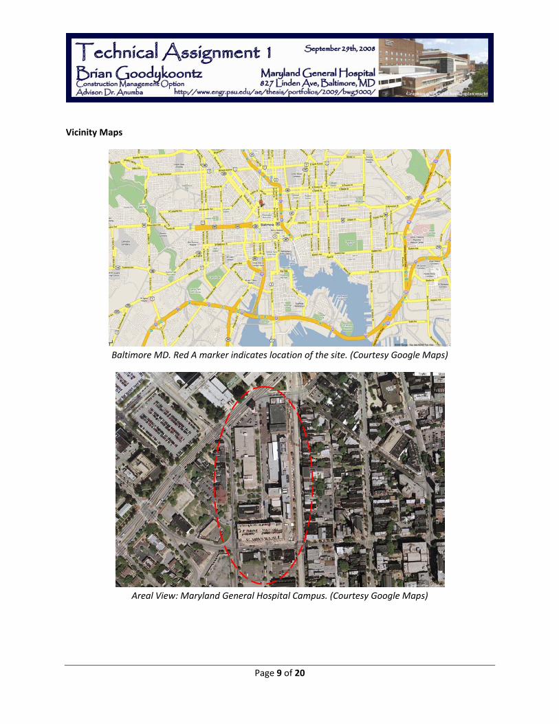
Vicinity Maps
Baltimore MD. Red A marker indicates location of the site. (Courtesy Google Maps)
Areal View: Maryland General Hospital Campus. (Courtesy Google Maps)

Page 10 of 20
LOCAL CONDITIONS
Preferred Method of Construction
Baltimore has a good mix of both concrete and steel structures. For this project however the preferred method of construction was with structural steel since the existing buildings to which the addition will attach are steel structures. Additionally, to complement the architecture of the existing buildings, a brick façade will be utilized.
City of Baltimore Concerns
- A parking and traffic lane on Linden Avenue will be needed for material laydown, deliveries, and installation of various systems. The traffic on Linen Avenue has been shifted into the far parking lane to maintain two‐way traffic on the street for the duration of the project. Appropriate signage, markings, and barriers have been utilized to comply with MOSH and OSHA requirements.
- Trench Drains in the courtyard will be protected from any sediment and debris getting into the storm drains during construction. A class E geotextile with 4‐6 inches of ¾” to 1 ½” stone will be used for the erosion and sediment control.
Availability of Construction Parking
- The hospital has given Barton Malow a surface lot at the corner of Linden and Martin Luther King Boulevard to use for their site trailers, material staging, and some construction parking.
- While there are several parking decks on the same block as the hospital, these lots are reserved strictly for patient and staff parking. The hospital has provided parking for contractors in a surface lot on the other side of the Madison Avenue at the south end of the campus.
Available Recycling and Tipping Fees
- As a provision of the contract with the hospital, dumpsters are provided and removed at the hospital’s expense.
- In Baltimore these tipping fees typically run around $400. There were no recycling dumpsters utilized for the project. Since the project is not seeking LEED certification this was not an issue.
Soil and Groundwater Conditions
- According to the geotechnical report, Amphibolite Bedrock which is suitable for bearing 30tsf was found between 62ft and 63ft in the courtyard area. Additionally, groundwater was found below 44ft in depth.
- During the drilling of the caissons little water was encountered, mainly after a substantial rainfall. Pumps were used to remove the water but no permanent dewatering was necessary.

Page 11 of 20
CLIENT INFORMATION
Maryland General Hospital is one of the numerous hospitals in the University of Maryland Medical System providing healthcare to more than 110,000 patients in northwest Baltimore, annually. In recent years the hospital has received many honors for the extraordinary quality of service which they provide to patients. Such honors include being named one of “America’s Best Hospitals” and in the top 16 percent of hospitals nationwide. This Central Care Expansion addresses the need to update the facility and provides room for the hospital to grow. It is a continuation of their outstanding commitment to the community for present and future healthcare needs as it continues to grow. While the current operating room and intensive care unit facilities have gone through many technology upgrades since they were built in the 1950s and 1960s they are becoming outdated and are located too far apart in the existing hospital. This project brings these operating rooms, intensive care units, and a laboratory currently located in another building much closer together for more efficient operation of the hospital. As part of the funding process for the addition, the hospital has to obtain approval from the Maryland Health Commission. The commission is responsible for reviewing and approving healthcare projects in the state of Maryland. The commission has been a driving factor in some of the schedule requirements as the hospital has to meet certain deadlines. The project was broken into two phases as a risk mitigation strategy in the event that the hospital’s financial situation changed. The phasing allows the hospital to complete the more critical operating rooms and intensive care units without being committed to the completion of phase two. The hospital has several sequencing requirements to meet the needs of their patients. The room reconfigurations required that only a few rooms at a time be taken to renovate so that the department in which the work was being completed could stay operational. Additionally, the third floor pharmacy must be completed prior to the completion of the fourth floor because the existing pharmacy is in a portion of the fourth floor which has some partial demolition and reconfiguration for the new intensive care units.

Page 12 of 20
PROJECT DELIVERY SYSTEM
Project Organizational Chart
Maryland General Hospital Client
Barton Malow Company CM @ Risk
Bob Grottenthaler
Hord Coplan Macht
Project Architect Tim Barnhill
Cagley AssociatesStructural Engineer
University of Maryland Medical System
Owner Daryl Mealy
Leach Wallace Associates
MEP Engineer
Johnson Mirmiran & Thompson
Civil Engineer
Baltimore Steel Structural Steel
Fabricator/Erector
Finishes Inc.General Trades Contractor
Interior Specialists, IncDemolition Contractor
Joseph M. ZimmerMechanical Contractor
Cove ElectricElectrical Contractor
Banner Masonry Masonry Contractor
Capital Contracting Concrete Contractor
Reliance Fire Protection
Fire Protection
Madison Glass Glazing Contractor
Asbestos Specialist Infection Control
ECS Testing Agency
Aria Environment Air Monitoring
FeeLump Sum
Lump Sum

Page 13 of 20
PROJECT DELIVERY SYSTEM
As shown in the project organization chart above there are four key players in the delivery of the project. The University of Maryland Medical System is the building owner while Maryland General Hospital is the client and building occupant. The project is being delivered as a design bid build project. Hord Coplan Macht is the architect and Barton Malow Company is the construction manager at risk on the project. Hord Coplan Macht was selected as the project architect based on their vast experience with healthcare projects and their performance on previous projects for the hospital. Barton Malow has a good and long standing relationship with the University of Maryland and was selected for this project based on their competitive low bid.
As Hord Coplan Macht performed the architectural services out of their office and contracted several consultants for the various other aspects of the project. Johnson Mirmiran and Thompson is the civil engineer on the project and was responsible for the geotechnical analysis, and all site work design. Cagley and Associates is responsible for all the structural design while Leach Wallace Associates is responsible of all mechanical, electrical, and plumbing design for the project. There are several other consultants to the architect who provide acoustic, interior, conveying system, and fire protection design services.
Each subcontractor to Barton Malow on the project was the lowest competitive bid and is in a lump sum contract with Barton Malow. Each of these subcontractors is required to meet minimum MBE requirements in addition to having general liability and builders risk insurances. These subcontractors do not however have to provide a performance bond. In an effort to save the owner cost Barton Malow has purchased Subguard insurance for the project. This eliminates the need for individual performance bonds which should cut down the cost to insure performance on the project. Shown in the organization chart are some of the key subcontractors to the project.

Page 14 of 20
STAFFING PLAN
Barton Malow Company has staffed this job very similarly to other jobs of this size and scope. While this chart shows the general staffing of the project, the plan has been dynamic to accommodate the various stages of construction. As the steel erection approached, another superintendent, and another engineer were brought on to assist with the increased volume of construction in preparation for the steel to go up.
Project Director The project director oversees the project ensuring that the entire team has everything they need to complete their job. Jennifer attends the weekly owners meetings and acts as the liaison between Barton Malow and the University of Maryland Medical System
Project Manager The project manager is ultimately responsible for the successful completion of the project. Scott’s daily responsibilities include: writing all contracts, tracking and processing all change orders and pay applications, tracking all budget items, and ensuring that the long term schedule is met.
Project DirectorJennifer Macks
Project ManagerScott Mull
General Superintendent Michael Fama
Sr. Project EngineerSteven Herckner
Project EngineerKasey Kinney
Accountant Sarah Fisher

Page 15 of 20
Senior Project Engineer The senior project engineer is responsible for setting up and overseeing the submittal and rfi system for the project. Additionally, because of the added complexity of some of the steel on the project, Steve who has extensive experience with structural steel, was the primary reviewer of structural steel submittals.
Project Engineer The project engineer is responsible for tracking and posting all RFIs, submittals, and change bulletins. Additionally, the project engineer is responsible for monitoring and documenting the ICRA procedures throughout the duration of the project.
Superintendent The superintendent is responsible for maintaining creating and maintaining the schedule, scheduling daily activities, maintaining quality throughout the project, and enforcing the ICRA procedures.
Accountant The accountant is responsible for tracking all project costs and issuing subcontractor checks.

Page 16 of 20
Appendix A
Maryland General Hospital: Central care Expansion Project Schedule Summary

ID Task Name Duration Start Finish
1 Design 178 days Tue 1/2/07 Thu 9/6/07
2 Schematic Design/Programming 43 days Tue 1/2/07 Thu 3/1/07
3 Design Development 55 days Fri 3/2/07 Thu 5/17/07
4 Construction/Biding Documents 80 days Fri 5/18/07 Thu 9/6/07
5 Procurement 219 days Fri 9/7/07 Wed 7/9/08
6 Biding/ Selection Period 75 days Fri 9/7/07 Thu 12/20/07
7 Submittals/Shop Drawings/ Release 135 days Thu 1/3/08 Wed 7/9/08
8 Construction 493 days Wed 1/2/08 Fri 11/20/09
9 Phase 1 470 days Wed 1/2/08 Tue 10/20/09
10 NTP 0 days Wed 1/2/08 Wed 1/2/08
11 Mobilization 33 days Wed 1/2/08 Fri 2/15/08
12 Renovation/ Retrofit Existing Bu 266 days Mon 1/28/08 Mon 2/2/09
13 Cooling Tower, Chiller, AHU 84 days Mon 1/28/08 Thu 5/22/08
14 Reinforce Existing Columns/ 125 days Mon 3/3/08 Fri 8/22/08
16 Room Reconfigurations/ Ren 125 days Mon 4/7/08 Fri 9/26/08
15 Replace/Infill Existing Window 80 days Tue 10/14/08 Mon 2/2/09
17 New Construction 397 days Mon 4/14/08 Tue 10/20/09
18 Caissons/ New Foundations 50 days Mon 4/14/08 Fri 6/20/08
19 Steel Erection/ SOMD 60 days Mon 6/23/08 Fri 9/12/08
20 Topping Out 0 days Fri 9/12/08 Fri 9/12/08
21 Enclosure 69 days Tue 9/2/08 Fri 12/5/08
22 Fit-Out 3rd Floor Pharmacy 101 days Mon 9/8/08 Mon 1/26/09
23 3rd Floor Pharmacy Turnove 0 days Thu 1/29/09 Thu 1/29/09
24 Fit-out 4th Floor 272 days Mon 10/6/08 Tue 10/20/09
26 Mechanical Penthouse Fit-Ou 59 days Tue 10/21/08 Fri 1/9/09
25 Fit-out 5th Floor 242 days Mon 11/3/08 Tue 10/6/09
27 Phase 2 295 days Mon 10/6/08 Fri 11/20/09
28 NTP Phase 2 ?? 0 days Mon 10/6/08 Mon 10/6/08
29 Excavation 60 days Mon 10/6/08 Fri 12/26/08
30 Foundation Walls 30 days Mon 12/29/08 Fri 2/6/09
31 1st Floor Steel - Beams/Metal Dec 15 days Mon 2/9/09 Fri 2/27/09
32 Cutainwall Glass 40 days Mon 3/2/09 Fri 4/24/09
33 Fit-out Basement - 3rd Floors 150 days Mon 4/27/09 Fri 11/20/09
34 Closeout 78 days Wed 10/14/09 Fri 1/29/10
35 Commissioning 37 days Wed 10/14/09 Thu 12/3/09
36 Final Inspection, Punchlist 46 days Mon 11/2/09 Mon 1/4/10
37 Owner Furnished Owner Installed Equi 53 days Wed 11/18/09 Fri 1/29/10
38 Certificate of Occupancy 0 days Fri 1/29/10 Fri 1/29/10
Design
Schematic Design/Programming
Design Development
Construction/Biding Documents
Procurement
Biding/ Selection Period
Submittals/Shop Drawings/ Release
Construction
Phase 1
1/2 NTP
Mobilization
Renovation/ Retrofit Existing Building
Cooling Tower, Chiller, AHU Replacement
Reinforce Existing Columns/ Footings
Room Reconfigurations/ Renovations
Replace/Infill Existing Windows
New Construction
Caissons/ New Foundations in Courtyard
Steel Erection/ SOMD
9/12 Topping Out
Enclosure
Fit-Out 3rd Floor Pharmacy
1/29 3rd Floor Pharmacy Turnover/ Partial CO
Fit-out 4th Floor
Mechanical Penthouse Fit-Out, Equip
Fit-out 5th Floor
Phase 2
10/6 NTP Phase 2 ??
Excavation
Foundation Walls
1st Floor Steel - Beams/Metal Deck
Cutainwall Glass
Fit-out Basement - 3rd Floors
Closeout
Commissioning
Final Inspection, Punchlist
Owner Furnished Owner Installed Equipment
1/29 Certificate of Occupancy
e Jan e MarApr a Jun Jul u e Oct o e Jan e MarApr a Jun Jul u e Oct o e Jan e MarApr a Jun Jul u e Oct o e Jan e MarApr a Jun Jul u e Oct o e Jan e Mar00 Qtr 1, 200 Qtr 2, 200 Qtr 3, 200 Qtr 4, 200 Qtr 1, 200 Qtr 2, 200 Qtr 3, 200 Qtr 4, 200 Qtr 1, 200 Qtr 2, 200 Qtr 3, 200 Qtr 4, 200 Qtr 1, 201 Qtr 2, 201 Qtr 3, 201 Qtr 4, 201 Qtr 1, 201
Task
Split
Progress
Milestone
Summary
Project Summary
External Tasks
External Milestone
Deadline
Page 1
Project: Maryland General HospitalDate: Sun 9/28/08

Page 17 of 20
Appendix B
Maryland General Hospital: Central care Expansion D4 Cost Estimate

Statement of Probable CostSaturday, September 27, 2008 Page 1
Maryland General Hospital - Jan 2010 - MD - Baltimore
Prepared By: Brian Goodykoontz Prepared For: Faculty Consultant: Dr. AnumbaAE Senior Thesis: Class of 2009 The Pennsylvannia State UniversityThe Pennsylvannia State University 104 Eng. Unit AUniversity Park, PA 16801 University Park, PA 16801585-269-9551 Fax: 814-865-6394 Fax:814863-4789
Building Sq. Size: 97040 Site Sq. Size: 1306800Bid Date: 12/1/2007 Building use: Medical
No. of floors: 5 Foundation: CASNo. of buildings: 1 Exterior Walls: CON
Project Height: 85.5 Interior Walls: GYP1st Floor Height: Roof Type: BIT
1st Floor Size: Floor Type: VCTProject Type: ADD/REN
Division Percent Sq. Cost Amount 00 Bidding Requirements 2.77 6.40 621,418
Bidding Requirements 2.77 6.40 621,418
01 General Requirements 5.46 12.60 1,222,962General Requirements 5.46 12.60 1,222,962
02 Site Work 7.54 17.41 1,689,911Site Work 7.54 17.41 1,689,911
03 Concrete 11.29 26.08 2,530,875Concrete 11.29 26.08 2,530,875
04 Masonry 2.43 5.61 544,401Masonry 2.43 5.61 544,401
05 Metals 6.07 14.03 1,361,191Metals 6.07 14.03 1,361,191
06 Wood & Plastics 4.08 9.43 915,547Wood & Plastics 4.08 9.43 915,547
07 Thermal & Moisture Protection 5.70 13.18 1,278,634Thermal & Moisture Protection 5.70 13.18 1,278,634
08 Doors & Windows 3.85 8.89 862,245Doors & Windows 3.85 8.89 862,245
09 Finishes 9.63 22.25 2,159,309Finishes 9.63 22.25 2,159,309
10 Specialties 0.22 0.52 50,067Specialties 0.22 0.52 50,067
11 Equipment 11.75 27.15 2,634,733Equipment 11.75 27.15 2,634,733
14 Conveying Systems 0.55 1.28 124,027Conveying Systems 0.55 1.28 124,027
15 Mechanical 19.89 45.93 4,457,514Mechanical 19.89 45.93 4,457,514
16 Electrical 8.75 20.21 1,961,527Electrical 8.75 20.21 1,961,527
Total Building Costs 100.00 230.98 22,414,361
Total Non-Building Costs 100.00 0.00 0
Total Project Costs -- -- 22,414,361

Page 18 of 20
Appendix C
2008 RS Means Square Foot Costs Hospitals 4‐8 Stories


Page 19 of 20
Appendix D
Maryland General Hospital: Central care Expansion Existing Conditions Site Plan

Site Utilities Pl
Notes:
Four Sanitary Lines to the Courtyard are new lines for the addition
Electric
Water
Existing Trench Drain
PlanScale: 1”=20’
are new lines for the additionFiberoptic/Tel
Sanitary

Howard St
Existing Hospital
7 Stories
E i ti H it l
Existing Armory Building Additione Existing Hospital
2 Stories4 Stories 4 Stories Over Existing
6 Stories In Courtyard
Existing
CourtyardEMT
Entra
nce
MainEntranceER
DmpstrLinden AveEntranceER
Entrance
Parking Garage
6 Stories
Parking Garage
Existing Medical Office Building Existing
(Patient/ Staff Parking Only)
Parking Garage
4 Stories
(Patient/Staff Parking Only)
4 Storiesg
Administrative Building
6 Stories
Sea Containers for Material
Parking Only)
Material Storage
C t d St l E tiLegend
FenceSite Logistics
PlGate Pedestrian Route Doctor Parking
Metered ParkingFence Jersey Barrier +
Courtyard Steel Erection
Construction Deliveries
Fence PlanMaterial Laydown
Metered ParkingFence Jersey Barrier + Fence
Scale: 1”=80’

Howard St
Existing Hospital
7 Stories
E i ti H it l
Existing Armory Building Additione Existing Hospital
2 Stories4 Stories 4 Stories Over Existing
6 Stories In Courtyard
Existing
CourtyardEMT
Entra
nce
MainEntranceER
DmpstrLinden AveEntranceER
Entrance
Parking Garage
6 Stories
Parking Garage
Existing Medical Office Building Existing
(Patient/ Staff Parking Only)
Parking Garage
4 Stories
(Patient/Staff Parking Only)
4 Storiesg
Administrative Building
6 Stories
Sea Containers for Material
Parking Only)
Material Storage
N th St l E tiLegend
FenceSite Logistics
PlGate Pedestrian Route Doctor Parking
Metered ParkingFence Jersey Barrier +
North Steel Erection
Construction Deliveries
Fence PlanMaterial Laydown
Metered ParkingFence Jersey Barrier + Fence
Scale: 1”=80’