Marvelmind Indoor Navigation System Operating manual · 4 Version changes V2019_10_31 - Industrial...
172
Marvelmind Indoor Navigation System Operating manual v2019_10_31 www.marvelmind.com
Transcript of Marvelmind Indoor Navigation System Operating manual · 4 Version changes V2019_10_31 - Industrial...

Marvelmind Indoor Navigation System
Operating manual
v2019_10_31
www.marvelmind.com

2
Table of contents 1. Executive summary .................................................................................................................................. 7
1.1 Legend ............................................................................................................................................. 9
2. Basics of the system .............................................................................................................................. 10
2.1 What’s in the box ........................................................................................................................... 10
2.2 Indoor Navigation System architectures ........................................................................................ 11
2.3 Indoor “GPS” System close-up and internal view .......................................................................... 12
3. System elements ................................................................................................................................... 14
3.1 Stationary beacon .......................................................................................................................... 14
3.2 Mobile beacon a.k.a. “hedgehog” .................................................................................................. 15
3.3 Modem/router................................................................................................................................. 16
3.4 Different types of beacons ............................................................................................................. 17
3.4.1 Super-Beacon ................................................................................................................................ 17
3.4.2 Mini-RX beacon ............................................................................................................................. 19
3.4.3 Mini-TX beacon .............................................................................................................................. 21
3.4.4 Beacon Industrial-TX ..................................................................................................................... 22
3.4.5 Beacon Industrial-RX ..................................................................................................................... 24
3.4.6 Industrial Super-Beacon Metal-25kHz ........................................................................................... 26
3.4.7 HW v4.9 beacon ............................................................................................................................ 27
3.5 Beacon comparison ....................................................................................................................... 28
4. Setting up the system (NIA) ................................................................................................................... 29
4.1 Starter Set Super-NIA-3D .............................................................................................................. 29
4.2 Starter Set HW v4.9 ....................................................................................................................... 36
4.3 Starter Set NIA-01-3D .................................................................................................................... 43
4.4 Starter Set NIA-SmallDrone ........................................................................................................... 49
4.5 Starter Set NIA-02-2D .................................................................................................................... 55
4.6 Starter Set Industrial-NIA-01 .......................................................................................................... 62
5. Setting up the system (IA)...................................................................................................................... 69
5.1 Starter Set IA-01-2D ...................................................................................................................... 69
5.2 Starter Set IA-02-3D ...................................................................................................................... 76
6. Dashboard menu and parameters ......................................................................................................... 83
6.1 Dashboard general view ................................................................................................................ 83
6.2 Table of distances .......................................................................................................................... 84
6.3 Devices list ..................................................................................................................................... 86
6.4 Visualization settings ..................................................................................................................... 87
6.5 Map Settings .................................................................................................................................. 88
6.6 Modem/beacon’s quick control panel ............................................................................................ 89
6.7 CEILLING and MIRRORING buttons on the Dashboard ............................................................... 90
6.8 Modem Settings ............................................................................................................................. 91
6.9 Radio frequency band and Carrier frequency .............................................................................. 107
6.10 Different hedgehog colors in the Dashboard ............................................................................... 108

3
6.11 Different stationary beacons’ colors in the Dashboard ................................................................ 109
7. SW feature/settings descriptions ......................................................................................................... 110
7.1 Licenses ....................................................................................................................................... 110
7.2 Floors feature (FN0011) .............................................................................................................. 112
7.3 Submap Settings ......................................................................................................................... 115
7.4 Axis rotation feature (FN0002) ..................................................................................................... 116
7.5 Vertical submaps feature (FN0003) ............................................................................................. 118
7.6 Handover Zones Setting .............................................................................................................. 121
7.7 Submaps feature (FN0004) ......................................................................................................... 122
7.8 Paired beacons (FN0005) ............................................................................................................ 128
7.9 Map settings ................................................................................................................................. 129
7.10 Hedge color change (FN0006) .................................................................................................... 130
7.11 Payload streaming (FN0007) ....................................................................................................... 132
7.12 IMU feature (FN0008) .................................................................................................................. 133
7.13 IMU axis positioning ..................................................................................................................... 135
7.14 Player feature (FN0009) .............................................................................................................. 136
7.15 Real-time player feature (FN0010) .............................................................................................. 139
7.16 CSV format .................................................................................................................................. 141
8. Interfaces ............................................................................................................................................. 142
8.1 Beacon HW v4.9 external interface 4x4 pinout top view ............................................................. 143
8.2 Modem HW v4.9 external interface pinout top view .................................................................... 144
8.3 Super-beacon external interface pinout top view ........................................................................ 145
9. Advanced system settings and optimization ........................................................................................ 146
9.1 Time Division Multiple Access (TDMA) ....................................................................................... 147
9.2 Increasing update rate ................................................................................................................. 149
9.3 Reducing delay ............................................................................................................................ 150
9.4 How to Place Beacons ................................................................................................................. 151
9.5 Using the Oscilloscope ................................................................................................................ 152
9.6 Proper Ultrasonic Signal Detection .............................................................................................. 153
9.7 Using hedgehog.log file ............................................................................................................... 154
9.8 System Accuracy Evaluation ....................................................................................................... 155
9.9 Calibration of the accelerometer .................................................................................................. 156
9.10 Settings to obtain correct north direction ..................................................................................... 158
9.11 Communication of Pixhawk with Marvelmind mobile beacon ...................................................... 159
9.12 Sending path to robot .................................................................................................................. 160
9.13 Proper ultrasonic coverage ......................................................................................................... 164
9.14 Sensors settings: example for 2D and mobile beacon ............................................................... 166
9.15 Powering beacons ....................................................................................................................... 167
10. Frequently Asked Questions ........................................................................................................ 168
11. Troubleshooting check-list ........................................................................................................... 170
12. Contacts ....................................................................................................................................... 172

4
Version changes
V2019_10_31
- Industrial Super-Beacon Metal-25kHz described
- Starting up chapters for every starter set described
- Super-Beacon and Super-Beacon outdoor described
- Improved photos
- Reception diagrams for HW v4.9 improved
- Oscilloscope chapter improved
- Minor fixes and improvements
V2019_07_02
- Troubleshooting improved
- Architectures comparison improved
- Minor fixes and improvements
V2019_06_25
- TDMA modes described
- Stationary beacons’ colors described
- Minor fixes and improvements
V2019_06_13
- Delay tuning described
- Update rate tuning described
- Minor fixes and improvements
V2019_06_07
- F.A.Q. and Troubleshooting improved
- Architectures comparison improved
- Receiving and transmitting angles illustrations added (v4.9 chapter and Mini-RX chapter)
- Ceiling and mirroring buttons described
V2019_06_03
- TDMA described
V2019_05_28
- IMU axis positioning fixed
- IA details added
- Troubleshooting improvements
- Minor fixes and improvements
V2019_05_16
- Introduction of the Legend
- Added missing video on page 34
- Minor fixes and improvements
V2019_04_30
- DFU programming described
- Magnetic reset for Industrial beacons and DFU programming described
- Minor fixes
V2019_04_04
- Starting up the system description for different Starter Sets (NIA, Industrial NIA and IA)
- Sending path to robot described
V2019_03_18

5
- New names for beacons: DSP => Mini-RX, Mini-beacon => Mini-TX, Beacon-TX-25-IMU-
IP67-RS485 => Industrial-TX, Beacon-RX-IMU-IP67-RS485 => Industrial-RX
- Starting up the system description for different Starter Sets
V2019_02_05
- Licenses described
- Minor fixes and improvements
V2019_01_29
- Mini-RX Inverse SW flashing described
- Added new types of beacons
- Minor fixes and improvements
V2019_01_12
- Mini-RX beacon and Mini-TX described
- IMU axis described
- Minor fixes and improvements
V2018_12_02
- Major new feature – support for 255 beacons and 255 submaps per modem
- New feature: user must setup handover zones between submaps to guarantee handover
quality for complex maps with multi-floor and similar
- New feature: default wireless connection is setting is now 153kbps (used to be 38kbps).
Radio profile 153kbps provides radio coverage range nearly as much as 38kbps and
update rate nearly as high 500kbps, i.e. it is a middle of 38kbps and 500kbps, combining
the best of both
- Correction: USB streaming in power save mode improved
- Correction: Zero IMU button in the Dashboard is improved, while button Reset IMU is
removed completely
- Correction: ultrasound TX is not reset to 31kHz when Default button is pressed. Now,
several types of ultrasonic frequencies supported, so 31kHz is not anymore default
ultrasonic frequency for all beacons
- Improved: both energy saving and tracking quality with Power Saving mode enabled
- Improved: only beacons with selected tick in the Dashboard lower menu will be accepted
to the network – not any addresses. This improves predictability of the network, when there
many beacons that may not belong to the network. Their attempts to join the network will
be blocked
- Improved: now, submaps support up to 4 beacons only. More than that – build another
submap. Up to 255 beacons and up to 255 submaps are supported per beacon
- Bug fix: improved map building with active hedgehog
- Bug fix: duplicated address might work incorrectly in some cases
V2018_11_08
- Real-time player feature described
V2018_08_30
- New SW features described
- New Dashboard view described
V2018_08_03
- Calibration of accelerometer described
- F.A.Q. updated
- Troubleshooting guide described
- Refreshed links
- Player feature described
- IMU feature described

6
- Minor fixes
V2017_12_29
- SW features paragraph updates
- General updates
- Sending path to robot
- Radio frequency band switch in latest Dashboard version
- Sending path to robot
- Paired beacons feature described
- Submap feature help video
- Different hedgehog colors in the Dashboard
- FAQ updates
V2017_11_01
- Added Sensors settings
- Added Dashboard features
- FAQ
- Fresh Dashboard screenshots
- General updates
V2017_09_08
- Added estimation of accuracy of distances measurement
- Added Raw inertial sensors data
- Added Communication of Pixhawk with Marvelmind mobile beacon
- Added Optimal settings for stationary beacons in small and big rooms
- Added Optimal settings for noisy environment
V2017_07_20
- Cleaned up description and some corrections were added
- Description of HW v4.5 removed from this manual and given in the previous version of the
manual, which can be found here:
http://www.marvelmind.com/pics/marvelmind_navigation_system_manual_HW_v4.5.pdf
- Description of HW v4.9 added
- Introduced plastic housing for beacons and modem
- Introduced 915MHz variant for the US market (HW v4.9 only)
- General updates and description improvements
- Submaps described
- HEX and DFU firmware general updates + new links
- Obtaining raw data from inertial sensors
- Settings to get correction north direction

7
1. Executive summary
Marvelmind Indoor Navigation System is an off-the-shelf indoor navigation system, designed to provide precise (±2cm) location data to autonomous robots, vehicles (AGV), and copters. It can also be used to track moving objects via mobile beacons attached to them. Other applications include, for example, forklifts, virtual reality (VR) systems, helmets for construction workers or miners, etc.
The navigation system consists of a network of stationary ultrasonic beacons interconnected via radio interface in a license-free band, one or more mobile beacons installed on objects to be tracked and modem providing gateway to the system from PC or other computers.
Mobile beacon’s location is calculated based on a propagation delay of an ultrasonic pulses (Time-Of-Flight or TOF) between stationary and mobile beacons using trilateration algorithm.
The system can build the map of stationary beacons automatically (For Non-Inverse
Architecture). In simple cases, no additional manual data input or any manual
distance measurements are required. This map formed once can be frozen and
stored in modem’s memory and the system becomes fully active within 7 to 10
seconds after the modem is powered.
Minimum configuration requirements (Non-Inverse Architecture) to ensure optimal performance of the Marvelmind Indoor Navigation System:
- For 3D (X, Y, Z) tracking: an unobstructed line of sight (hearing) between
a mobile beacon and 3 or more stationary beacons within 30 meters
- For 2D (X, Y) tracking - an unobstructed line of sight (hearing) between a
mobile beacon and 2 or more stationary beacons within 30 meters
Fig. 1: Example of starter set based on Super-beacons

8
Key capabilities:
Parameter Technical Specifications
Distance between
beacons
- Reaches up to 50 meters in lab conditions (Mini-RX beacon to HW v4.9 with RX4 only)
- Recommended distance is 30 meters (Transducer4 on the first beacon is looking straight at
the Transducer4 on the second beacon, other transducers are switched off)
Coverage area - Reaches up to 1000 m2 with the Starter Set configurations
- Coverage for larger territories is provided using submap – like cells in cellular networks
Location precision - Absolute: 1–3% of the distance to the beacons
- Differential precision: ±2 cm
Location update
rate
- 1/20Hz to 25Hz (Ultrasonic based only)
- 100Hz with ultrasonic + IMU fusion enabled
- Can be set manually via Dashboard software
- Depends on the distance between mobile and stationary beacons (shorter distance—higher update rate)
- Depends on the number of mobile beacons (Non-Inverse Architecture; for Inverse Architecture no such dependency)
- Depends on the radio profile (500kbps vs. 38kbps)
- Slightly depends on the number of stationary beacons—dependence is not the same as for mobile beacons
Power supply
Internal: 1000mAh LiPo battery (HW v4.9)
- Battery lifetime: from 2 days to several months depending on the mode of operations
*For other types of beacons look to the comparison table
External: micro USB – recommended for permanent use
Weight
Mobile beacon (HW v4.9) from the starter set:
- 59 grams (including 1000mAh battery, HW v4.9 housing and 50mm antenna)
- 27 grams (HW v4.9, bare board w/o battery)
*For other types of beacons look to the comparison table
Beacon size Size: 55x55x33 mm (with 50mm antenna: 55x55x65mm) (HW v4.9)
*For other types of beacons look to the comparison table

9
1.1 Legend
Important

10
2. Basics of the system
2.1 What’s in the box
2.1.1 HW v4.9 Starter Set:
- 5 x Super-beacons
- 1 x Modem/Router
2.1.2 Mini-RX Starter Set:
- 4 x Mini-RX beacons
- 1 x Mobile beacon (HW v4.9) + IMU (aka “hedgehog”)
- 1 x Modem/Router
*This is just an example of two starter sets.
More options you can see on our site: Products

11
2.2 Indoor Navigation System architectures
Marvelmind Indoor Navigation System provides high-precision (±2cm) indoor
coordinates for autonomous robots and systems (“indoor GPS”). A brief description
of the key elements of the system is given on the scheme below.
IA and NIA SW differs
For IA you should use stationary beacons with different frequencies
Below you can see 2 types of architectures: Non-Inverse (NIA) and Inverse (IA):

12
2.3 Indoor “GPS” System close-up and internal view
Here, you can see how system elements look like
- Super-beacon
- HW v4.9 modem (without housing)
- Mini-RX beacon
- Mini-TX

13
- HW v4.9 beacon with Mini-TX size comparison
- Beacon Industrial-RX
- Beacon Industrial-Super

14
3. System elements
3.1 Stationary beacon
- Usually, mounted on the walls or ceilings above the robot
with ultrasonic sensors facing down—to provide the most
robust unobstructed ultrasonic signal coverage to the robot.
However, for automatic landing and indoor navigation of
copters, for example, it is recommended to install mobile
beacon horizontally on the belly of the copter so that the
beacon would be looking downwards
- The position and orientation of the beacons should be
chosen in a way that provides maximum ultrasonic signal
coverage. System efficacy strongly depends on the quality
of ultrasonic signal received by stationary beacons
- Stationary beacons emit and receive ultrasound during the map configuration period. Once
the map is formed and frozen, they only work as the receivers
- Stationary beacons have no exterior differences with regard to mobile beacons
- Inertial measurement unit (IMU) is not installed on the stationary beacons
- The mobile and stationary beacons can be easily interchanged by selecting corresponding
option (except for IMU) during configuration in the Dashboard
- There are 433MHz and 915MHz versions available. A proprietary radio protocol is used for
communication and synchronization. Other ISM bands are available upon request as well
- Stationary beacon can be equipped with full-size 165mm antenna (for 433 MHz), which
provides more robust radio connection between modem and beacons (for HW v4.9)
Fig.1: Super-beacon as an example

15
3.2 Mobile beacon a.k.a. “hedgehog”
- The mobile and stationary beacons can be easily
interchanged by selecting the option in the Dashboard
- The mobile beacons designed to be placed on a
robotic vehicle, copter/drone, AGV, or helmet to trace
its location. Formally speaking, location of the mobile
beacon is traced—not the robot itself. Since the sizes
and the location of the central point of the mobile
beacon and the robot are different, the difference
taken into account in the robot’s software (SW)
- It is recommended to place the mobile beacon
horizontally to provide optimal ultrasonic coverage in
the upper hemisphere
- Its sensors must not be covered with anything that can reduce the strength of ultrasonic
signal. For example, the system won’t normally work, if one puts the mobile beacon in a
plastic box
- The beacon’s coordinates are updated according to the rate set on the Dashboard
- The system may contain one or several mobile beacons. Current implementation relies on
a time-division multiple access approach. Thus, if two mobile beacons are activated, they
share the same system bandwidth. It means that, if the 16 Hz update rate is selected in the
Dashboard and there are 2 mobile beacons in the system, each beacon’s location will be
updated with the rate of 16Hz/2 ~ 8Hz. If there are 3 mobile beacons => 16Hz/3 ~ 5Hz, etc.
Future SW implementation may contain different solution that will improve update rates in
setups with multiple mobile beacons
- Location data is obtained either from the “hedgehog” via USB (virtual UART), UART, SPI,
or from the modem/router via USB (virtual UART). More information on interfaces can be
found here (Mini-RX beacon do not have pinouts, only over micro-USB)
- Data from the beacon sent in a streaming format identical to that of GPS (NMEA 0183)
- There are 433MHz and 915MHz (915/868MHz only for Mini-RX beacon) versions available.
Proprietary radio protocol is used for communication and synchronization
- The “hedgehog” has been successfully integrated with Windows PC, Linux machines,
Raspberry Pi, Arduino boards, Intel boards, etc.
Fig.1: Super-beacon as an example

16
3.3 Modem/router
- Modem is the central controller of the system. It must always be
powered when the Navigation System is working. It is recommended
to use an active USB hub for that purpose or even a regular cellular
phone USB power supply. A USB power bank can also be used.
- The modem is also used to set up the system, monitor it, and interact
with the Dashboard.
- It can be placed anywhere within radio coverage for permanent radio
connection with all beacons—usually in the radius of up to 100 meters
with antennas from the Starter Set.
- Radio coverage further extended to a few hundred meters by using a
lower bitrate of 38kbps and full-size (165mm for a 433MHz band)
antennas, which have been tested to provide up to 400 m in ideal
conditions.
- There are 433MHz and 915MHz versions available.
- A proprietary radio protocol used for communication and synchronization
between modem and beacons.
Fig.3: HW v4.9 as an example
17
3.4 Different types of beacons
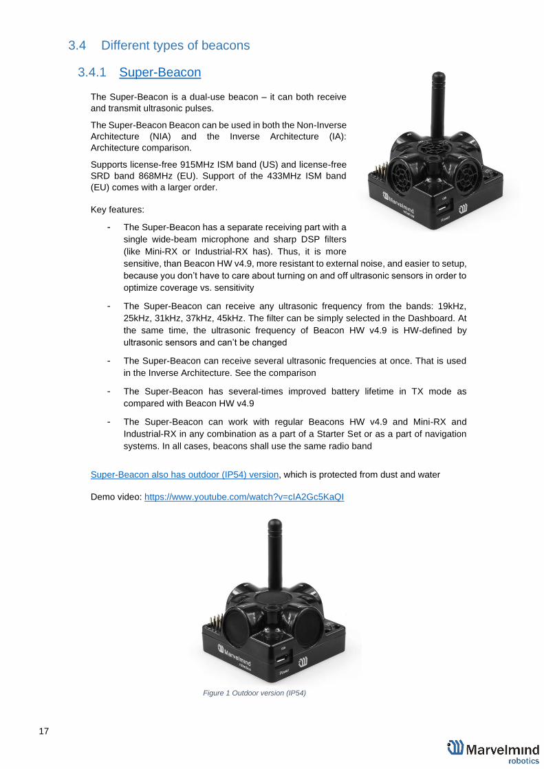
3.4.1 Super-Beacon
The Super-Beacon is a dual-use beacon – it can both receive
and transmit ultrasonic pulses.
The Super-Beacon Beacon can be used in both the Non-Inverse
Architecture (NIA) and the Inverse Architecture (IA):
Architecture comparison.
Supports license-free 915MHz ISM band (US) and license-free
SRD band 868MHz (EU). Support of the 433MHz ISM band
(EU) comes with a larger order.
Key features:
- The Super-Beacon has a separate receiving part with a
single wide-beam microphone and sharp DSP filters
(like Mini-RX or Industrial-RX has). Thus, it is more
sensitive, than Beacon HW v4.9, more resistant to external noise, and easier to setup,
because you don’t have to care about turning on and off ultrasonic sensors in order to
optimize coverage vs. sensitivity
- The Super-Beacon can receive any ultrasonic frequency from the bands: 19kHz,
25kHz, 31kHz, 37kHz, 45kHz. The filter can be simply selected in the Dashboard. At
the same time, the ultrasonic frequency of Beacon HW v4.9 is HW-defined by
ultrasonic sensors and can’t be changed
- The Super-Beacon can receive several ultrasonic frequencies at once. That is used
in the Inverse Architecture. See the comparison
- The Super-Beacon has several-times improved battery lifetime in TX mode as
compared with Beacon HW v4.9
- The Super-Beacon can work with regular Beacons HW v4.9 and Mini-RX and
Industrial-RX in any combination as a part of a Starter Set or as a part of navigation
systems. In all cases, beacons shall use the same radio band
Super-Beacon also has outdoor (IP54) version, which is protected from dust and water
Demo video: https://www.youtube.com/watch?v=cIA2Gc5KaQI
Figure 1 Outdoor version (IP54)

18
Figure 4 Receiving diagram (with digital microphone)
Figure 2 Transmitting diagram (with sensors) Figure 3 Transmitting diagram (with sensors)
Figure 5 Receiving diagram (with digital microphone)

19
3.4.2 Mini-RX beacon
The Mini-RX Beacon can be used in both the Non-Inverse
Architecture (NIA) and in the Inverse Architecture (IA): NIA and IA
comparison
The Mini-RX beacon HW differs from the regular Beacon HW v4.9
in several ways:
- It is an RX-only beacon, i.e. it can receive, but it cannot
transmit ultrasonic signal
- The fact that it is RX-only makes it far more sensitive, i.e. you will get a longer range
between Beacon HW v4.9 and Mini-RX v5.xx than between Beacon HW v4.9 and
Beacon HW v4.9
- Mini-RX beacon can receive any ultrasonic frequency from the bands: 19kHz, 25kHz,
31kHz, 37kHz, 45kHz, 56kHz. The filter can be simply selected in the Dashboard. At
the same time, the working ultrasonic frequency of Beacon HW v4.9 is HW-defined by
ultrasonic sensors and can’t be changed
- Mini-RX beacon can receive several ultrasonic frequencies at once. That is used in
Inverse Architecture. See the comparison: NIA and IA comparison
- The Mini-RX Beacon is significantly smaller than Beacon HW v4.9
- Can play a role of stationary beacon when imputing coordinates manually
- Can play a role of mobile beacon (in inverse system)
- Has digital microphone, which is more sensitive than regular sensors
- Can’t emit ultrasound
- Light weighted
- Can be water-protected
- The component of the Marvelmind Helmet and Marvelmind Watch
- It has 360° reception angle (horizontally) and 180° reception angle (vertically)
Reception diagram. Digital microphone has about 360° (horizontally) and 180° (vertically)
reception angle
Mini-RX beacon may be over discharged. In that case do the following:
Turn off the beacon with DIP switches and charge it for 1 hour. Then turn the beacon on,
flash the latest SW via DFU Programming and charge it for 1 hour again

20
3.4.2.1 External microphone extension
This modification of the Mini-RX beacon allows you to bring the receiving microphone to any place on the
robot or clothing. Due to this, the microphone body itself will not interfere, and will not be visible. It allows
you to create more accurate implantation.
It is also possible to use 2 external microphones to calculate the direction, or to improve and increase the
reception area.
Dual microphones modification:
Mini-RX beacon
External microphone
Mini-RX beacon hidden
inside
External Microphone 2 External Microphone 1
Robot’s head
47mm
210mm

21
3.4.3 Mini-TX beacon
The Mini-TX is a TX only beacon, i.e. it can transmit, but cannot
receive ultrasound
Comparison to Beacon HW v4.9:
- Smaller size and lighter: 47x42x15mm & 25g vs.
55x55x33mm & 62g (or 55x55x64mm with antenna)
- TX only, i.e. Mini-TX can only transmit ultrasonic and cannot
receive. Beacon HW v4.9 is dual use: can receive and transmit ultrasonic
- Battery – 250mAh vs. 1000mAh in a regular beacon. But Mini-TX has a new
more efficient ultrasonic TX module, thus, battery lifetime in TX mode is even
superior to the Beacon HW v4.9
- Tested battery lifetime with 8Hz – 96h. With lower update rate – nearly
proportionally longer. Very efficient ultrasonic TX module
- Mini-TX has only USB (virtual UART) output – no additional pins
- Mini-TXs always have embedded IMU – newer and better, but it has 3D
accelerometer and 3D gyroscope, but no magnetometer (which we do not
recommend using indoors anyway, due to magnetic field distortion indoor)
- Embedded antenna – smaller size, but smaller radio coverage ~50m with
regular Modem HW v4.9 as compared with ~100m of Beacon HW v4.9 with
Modem HW v4.9
- Range in ultrasonic is virtually on par with regular Beacon HW v4.9 – up to
30m with Beacon HW v4.9 as RX beacon. At the same time, for example, a
combination of Mini-RX RX beacon + Mini-TX TX provide a better coverage
and a stronger signal, than Beacon HW v4.9 + Beacon HW v4.9
- This HW is for the 915MHz band (US band) only, i.e. 433MHz (EU band) is
not supported and not planned. Future HW versions will support another ISM
band for the EU – 868MHz. With further limitation of radio coverage, this HW
(the 915MHz version) can be used for the 868MHz band already now

22
3.4.4 Beacon Industrial-TX
- TX-only beacon – can transmit ultrasonic,
but can’t receive it
- Electronics is IP67 protected
- Special IP67-protected 25-kHz transducers
- External antenna with SMA connector for
extended radio range
- Corresponding IP67 connectors (male part)
included
- No battery inside
- Extended working temperature range from -
40°C to +50°C (not tested, provided by
design)
- Embedded reset switch and DFU switch – magnetic control
- Two IP67 external connectors:
RS485 modification pinouts (Before Sep.2019)
RS485 modification pinouts (After Sep.2019)
CAN modification pinouts
- Can work together with modems with corresponding radio (radio bands must match)
- Can work with any Mini-RX beacon or Beacon HW v4.9 with 25kHz ultrasonic sensors
(radio bands must match)
- Most of all designed to work together with Outdoor versions of Mini-RX beacons: Mini-
RX “watch” and heavy outdoor Beacon-RX-IP67 (radio bands must match)
- Up to 30m with Beacon Mini-RX+IMU+Outdoor
Optional external IP67 converter ~110/220V to +12V

23
Uploading Beacon’s Industrial-RX or Beacon’s Industrial-TX SW to Industrial
Super-beacon may permanently damage Industrial Super-beacon board.
Determine carefully the version of your Industrial beacons: it
may be built before September 2019 and after September 2019.
If it is beacon from the late batch, you must use Industrial
Super-beacon SW. if you have beacons from the early batch,
use Industrial-RX or Industrial-TX SW. Stickers’ differences:
Later batch – Ind-RX-S or Ind-TX-S. Early batch – Beacon Ind-
RX or Beacon Ind-TX.

24
3.4.5 Beacon Industrial-RX
- RX-only beacon – can receive ultrasonic,
but can’t transmit it
- Electronics is IP67 protected
- Special IP67-membrane for ultrasonic
sensor
- External antenna with SMA connector for
extended radio range
- Corresponding IP67 connectors (male
part) included
- No battery inside by default – external power bank or external power supply (+12V 0r
+5V). But, optional variant with internal battery is possible
- Two IP67 external connectors:
- RS485 modification pinouts (Before Sep.2019)
- RS485 modification pinouts (After Sep.2019)
- CAN modification pinouts
- Extended working temperature range from -40°C to +50°C (not tested, provided by
design) – only for the version without battery
- Embedded reset switch and DFU switch – magnetic control
- Supports wide range of ultrasonic frequencies: 19/25/31/37/45/56 kHz
- Most of all designed to work together with heavy-outdoor version Beacon-TX-25-IMU-
IP67-RS485 – up to 30m range in ultrasonic
‒ Optional external IP67 converter ~110/220V to +12V

25
Uploading Beacon’s Industrial-RX or Beacon’s Industrial-TX SW to Industrial
Super-beacon may permanently damage Industrial Super-beacon board.
Determine carefully the version of your Industrial beacons: it
may be built before September 2019 and after September
2019. If it is beacon from the late batch, you must use
Industrial Super-beacon SW. if you have beacons from the
early batch, use Industrial-RX or Industrial-TX SW. Stickers’
differences: Later batch – Ind-RX-S or Ind-TX-S. Early batch –
Beacon Ind-RX or Beacon Ind-TX.
26
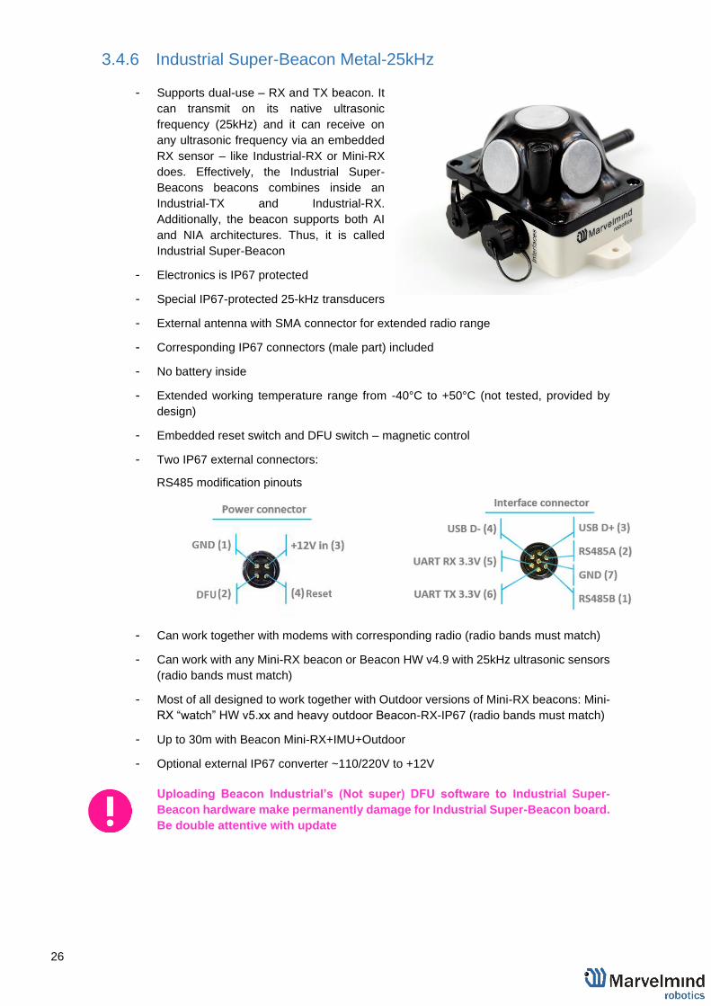
3.4.6 Industrial Super-Beacon Metal-25kHz
- Supports dual-use – RX and TX beacon. It
can transmit on its native ultrasonic
frequency (25kHz) and it can receive on
any ultrasonic frequency via an embedded
RX sensor – like Industrial-RX or Mini-RX
does. Effectively, the Industrial Super-
Beacons beacons combines inside an
Industrial-TX and Industrial-RX.
Additionally, the beacon supports both AI
and NIA architectures. Thus, it is called
Industrial Super-Beacon
- Electronics is IP67 protected
- Special IP67-protected 25-kHz transducers
- External antenna with SMA connector for extended radio range
- Corresponding IP67 connectors (male part) included
- No battery inside
- Extended working temperature range from -40°C to +50°C (not tested, provided by
design)
- Embedded reset switch and DFU switch – magnetic control
- Two IP67 external connectors:
RS485 modification pinouts
- Can work together with modems with corresponding radio (radio bands must match)
- Can work with any Mini-RX beacon or Beacon HW v4.9 with 25kHz ultrasonic sensors
(radio bands must match)
- Most of all designed to work together with Outdoor versions of Mini-RX beacons: Mini-
RX “watch” HW v5.xx and heavy outdoor Beacon-RX-IP67 (radio bands must match)
- Up to 30m with Beacon Mini-RX+IMU+Outdoor
- Optional external IP67 converter ~110/220V to +12V
Uploading Beacon Industrial’s (Not super) DFU software to Industrial Super-
Beacon hardware make permanently damage for Industrial Super-Beacon board.
Be double attentive with update

27
3.4.7 HW v4.9 beacon
HW v4.9 beacon can be used in both the Non-Inverse Architecture (NIA) and in the Inverse
Architecture (IA): NIA and IA comparison
Reception diagram. Each sensor has about 90° reception angle:
Figure 1 Transmitting diagram (with sensors)
Figure 2 Transmitting diagram (with sensors)

28
3.5 Beacon comparison
Here you can see more details about the different types of beacons:
https://marvelmind.com/pics/!_Marvelmind_Precise_Indoor_GPS_beacons_comparison.pdf

29
4. Setting up the system (NIA)
4.1 Starter Set Super-NIA-3D
The steps below describe the very first time you set up of the system. Super-beacons and modem required.
4.1.5 Unpack the system. Watch the help video (video describes unpacking of
the HW v4.9 Starter Set, but the packing is the same):
https://youtu.be/sOce7B2_6Sk
4.1.6 Charge all the beacons using USB cable. Full charging takes about 1-2
hours
4.1.7 Turn the beacons on: Place DIP switches as shown on the picture below
4.1.8 Download SW Pack
4.1.9 Update all the beacons (HEX programming):
‒ Run the Dashboard and update the SW for all beacons and
modem using Dashboard => Firmware => Choose the file =>
Program
30
‒ If you see the message “Not found modem connection to
computer through USB” in the Dashboard or your PC does not
recognize beacons/modem, it usually means that the STM32
driver is not installed. To install the driver, download it with link
at top window in the Dashboard and run the installation file, then
click on the link under and install the driver
Ensure that:
(a) You are programming the modem’s SW to the modem
and the beacon’s SW to the beacon
(b) You are using SW for Super-beacon, if you have Super-
beacon; and you have the SW from the same SW pack,
i.e., the Dashboard SW, modem SW, and beacon SW
must be from the same SW pack. Don’t mix SW
releases
If SW flashed SUCESSUFLY, MOVE DIRECTLY TO 4.1.10. If you have
some problems with HEX programming, use DFU programming:
DFU programming or SW uploading is used when HEX SW uploading in
the Dashboard cannot be used. For example, when you are updating
from a very old SW version or when the SW includes major changes to
the system and the only possible way to update the SW is via DFU
programming
- After the DFU SW upgrade, future SW upgrades can be done in
a regular manner via the Dashboard
- To start programming, move the beacon’s DIP switch to the DFU
programming mode, as described in the paragraph on DIP
switch modes
- Download the latest SW package, unzip it, and select the proper
version of the SW for your HW and for your frequency variant.
Remember that for DFU programming, you should use DFU SW
(DfuSe), not Dashboard’s .hex file
- Download DfuSe
- Here you will find different versions of DfuSe. v3.0.4 or v3.0.5,
whichever works the best for your Windows: DfuSe v3.0.4 or
DfuSe v.3.0.5
DFU Programming:
- Put DIP switch into Power = ON, DFU = ON
- Connect the beacon via USB to your PC
- Run DfuSe
- Press the RESET button on your beacon
- In the upper left corner of the DfuSe program, you will see
a device connected in the DFU mode
31
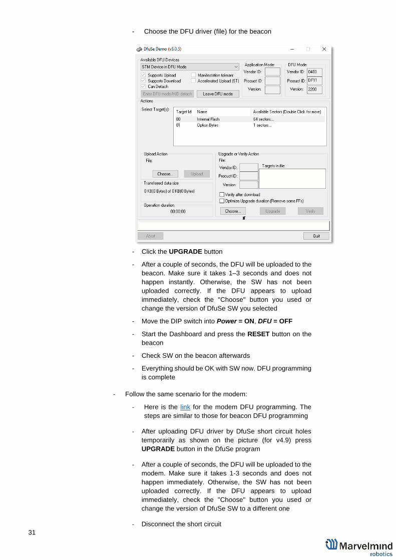
- Choose the DFU driver (file) for the beacon
- Click the UPGRADE button
- After a couple of seconds, the DFU will be uploaded to the
beacon. Make sure it takes 1–3 seconds and does not
happen instantly. Otherwise, the SW has not been
uploaded correctly. If the DFU appears to upload
immediately, check the "Choose" button you used or
change the version of DfuSe SW you selected
- Move the DIP switch into Power = ON, DFU = OFF
- Start the Dashboard and press the RESET button on the
beacon
- Check SW on the beacon afterwards
- Everything should be OK with SW now. DFU programming
is complete
- Follow the same scenario for the modem:
- Here is the link for the modem DFU programming. The
steps are similar to those for beacon DFU programming
- After uploading DFU driver by DfuSe short circuit holes
temporarily as shown on the picture (for v4.9) press
UPGRADE button in the DfuSe program
- After a couple of seconds, the DFU will be uploaded to the
modem. Make sure it takes 1-3 seconds and does not
happen immediately. Otherwise, the SW has not been
uploaded correctly. If the DFU appears to upload
immediately, check the "Choose" button you used or
change the version of DfuSe SW to a different one
- Disconnect the short circuit

32
- Start the Dashboard and press RESET button
- If you experience difficulties in DFU programming, please try
the following:
- Use a different computer with a different version of
Windows or another operating system
- Install a different DfuSe version (whichever works best
with your Windows)
If you have uploaded the latest firmware for all of the boards, you can start to
activate the system:
4.1.10 While the beacon or modem is connected to the Dashboard, click
the DEFAULT button on the Dashboard to upload the default
settings
4.1.11 Write down the beacon’s address for future use or change the
address at your convenience as shown here
4.1.12 Press the RESET button on your beacons and modem after
programming
4.1.13 After programming devices with the latest software, the modem and
beacons are ready for use
4.1.14 Place the stationary beacons on the walls vertically in a way that will
provide optimal ultrasonic coverage. It is recommended that you
start with a simple 4m x6m room or so and place the stationary
beacons on the opposite walls at a height of 1.85m (default). After
familiarizing yourself with the system, more complex configurations
can be made. The help video can be found here
4.1.15 Connect the modem/router via USB to a Windows PC with the
Dashboard installed

33
4.1.16 Run the Dashboard. In the left corner of the Dashboard, the modem
should be shown as connected
4.1.17 Wake up all beacons by selecting them on the Dashboard panel
Only 4 stationary beacons may be in 1 submap. If you wake up
more beacons, create new submap for them or it won’t be
displayed on the map and in the table of distances.
4.1.18 It may take up to 7-10 seconds for the beacons to wake up
4.1.19 Notice, that if the modem is not active and is not powered, the
beacons will go into sleep mode automatically after 1 minute
4.1.20 The system may run the frequency search, if it is the very first time
you are waking up the beacons. If this step does not work,
disconnect the modem and connect that beacon again via USB.
Press the DEFAULT button in the Dashboard and the Read All
button to make sure that the radio settings are the default ones
4.1.21 Check that the radio settings on the modem and the radio settings
on the beacon are the same
4.1.22 Now you can check the height of the beacons, RSSI, radio channel,
threshold, etc. on the panel on the right corner of the Dashboard
4.1.23 In the current version one modem supports 255 beacons. If you do
not see some of your connected beacons on the map, you may need
to scroll to find their addresses
4.1.24 Double click on the device both to put it into sleep mode and to wake
it up
4.1.25 The map will form and zoom in automatically
4.1.26 If the map does not form well, check the table of distances in the left
corner of the Dashboard. The cells must be colored in white; it

34
means the distances between stationary beacons are measured
correctly
4.1.27 If you see in the table some empty cells or marked yellow/red, it is
an indication that distances between Some beacons are measured
inconsistently or not measured at all. Try to re-position them
because usually there is an obstruction of some sort in the between
the beacons. It also may be different height of beacons’ position.
Reset all these beacons.
4.1.28 Use View => Table of distances to monitor the measured distances
between beacons
4.1.29 Freeze the map by clicking the button. Stationary beacons will stop
measuring relative distances and will be ready to measure distance

35
from the mobile beacon(s)
4.1.30 Turn on and wake up the mobile beacon following the same steps
as with the stationary beacon. More details in our video:
https://youtu.be/A4aRsjH2-_E
4.1.31 If you see on the devices’ panel in the Dashboard that the beacon is
colored orange, it means there are some differences in some of the
settings between beacons. For example, some sensors may be off
or some ultrasonic or radio settings may be different. You can
change the settings for sensors manually by clicking on the panel on
the upper right corner of the Dashboard to change the cells from
gray to green to turn on sensor. It is recommended that the default
settings on all beacons and the modem are used if this is your first
time using the system.
4.1.32 After you freeze the map of stationary beacons, wake up the mobile
beacon. After it wakes up, it will be traceable within 5-7 seconds.
4.1.33 The system is now fully operational.
4.1.34 In the dashboard, you can upload a picture / map of your room. You
can use a different picture for every floor. Go to Loading the floorplan

36
4.2 Starter Set HW v4.9
The steps below describe the very first time you set up of the system. Beacons HW v4.9 and modem required.
4.2.1 Unpack the system. Watch the help video:
https://youtu.be/sOce7B2_6Sk
4.2.2 Charge all the beacons using USB cable. Full charging takes about 1-2
hours
4.2.3 Turn the beacons on: Place DIP switches as shown on the picture below
4.2.4 Download SW Pack
4.2.5 Update all the beacons (HEX programming):
‒ Run the Dashboard and update the SW for all beacons and
modem using Dashboard => Firmware => Choose the file =>
Program
‒ If you see the message “Not found modem connection to
computer through USB” in the Dashboard or your PC does not
recognize beacons/modem, it usually means that the STM32
driver is not installed. To install the driver, download it with link

37
at top window in the Dashboard and run the installation file, then
click on the link under and install the driver
Ensure that:
(c) You are programming the modem’s SW to the modem
and the beacon’s SW to the beacon
(d) You are using SW for HW v4.9, if you have HW v4.9;
and you have the SW from the same SW pack, i.e., the
Dashboard SW, modem SW, and beacon SW must be
from the same SW pack. Don’t mix SW releases
If SW flashed SUCESSUFLY, MOVE DIRECTLY TO 4.2.6. If you have
some problems with HEX programming, use DFU programming:
DFU programming or SW uploading is used when HEX SW uploading in
the Dashboard cannot be used. For example, when you are updating
from a very old SW version or when the SW includes major changes to
the system and the only possible way to update the SW is via DFU
programming
- After the DFU SW upgrade, future SW upgrades can be done in
a regular manner via the Dashboard
- To start programming, move the beacon’s DIP switch to the DFU
programming mode, as described in the paragraph on DIP
switch modes
- Download the latest SW package, unzip it, and select the proper
version of the SW for your HW and for your frequency variant.
Remember that for DFU programming, you should use DFU SW
(DfuSe), not Dashboard’s .hex file
- Download DfuSe
- Here you will find different versions of DfuSe. v3.0.4 or v3.0.5,
whichever works the best for your Windows: DfuSe v3.0.4 or
DfuSe v.3.0.5
DFU Programming:
- Put DIP switch into Power = ON, DFU = ON
- Connect the beacon via USB to your PC
- Run DfuSe
- Press the RESET button on your beacon
- In the upper left corner of the DfuSe program, you will see
a device connected in the DFU mode

38
- Choose the DFU driver (file) for the beacon
- Click the UPGRADE button
- After a couple of seconds, the DFU will be uploaded to the
beacon. Make sure it takes 1–3 seconds and does not
happen instantly. Otherwise, the SW has not been
uploaded correctly. If the DFU appears to upload
immediately, check the "Choose" button you used or
change the version of DfuSe SW you selected
- Move the DIP switch into Power = ON, DFU = OFF
- Start the Dashboard and press the RESET button on the
beacon
- Check SW on the beacon afterwards
- Everything should be OK with SW now. DFU programming
is complete
- Follow the same scenario for the modem:
- Here is the link for the modem DFU programming. The
steps are similar to those for beacon DFU programming
- After uploading DFU driver by DfuSe short circuit holes
temporarily as shown on the picture (for v4.9) press
UPGRADE button in the DfuSe program
- After a couple of seconds, the DFU will be uploaded to the
modem. Make sure it takes 1-3 seconds and does not
happen immediately. Otherwise, the SW has not been
uploaded correctly. If the DFU appears to upload
immediately, check the "Choose" button you used or
change the version of DfuSe SW to a different one
- Disconnect the short circuit

39
- Start the Dashboard and press RESET button
- If you experience difficulties in DFU programming, please try
the following:
- Use a different computer with a different version of
Windows or another operating system
- Install a different DfuSe version (whichever works best
with your Windows)
If you have uploaded the latest firmware for all of the boards, you can start to
activate the system:
4.2.6 While the beacon or modem is connected to the Dashboard, click
the DEFAULT button on the Dashboard to upload the default
settings
4.2.7 Write down the beacon’s address for future use or change the
address at your convenience as shown here
4.2.8 Press the RESET button on your beacons and modem after
programming
4.2.9 After programming devices with the latest software, the modem and
beacons are ready for use
4.2.10 Place the stationary beacons on the walls vertically in a way that will
provide optimal ultrasonic coverage. It is recommended that you
start with a simple 4m x6m room or so and place the stationary
beacons on the opposite walls at a height of 1.85m (default). After
familiarizing yourself with the system, more complex configurations
can be made. The help video can be found here
4.2.11 Connect the modem/router via USB to a Windows PC with the
Dashboard installed

40
4.2.12 Run the Dashboard. In the left corner of the Dashboard, the modem
should be shown as connected
4.2.13 Wake up all beacons by selecting them on the Dashboard panel
Only 4 stationary beacons may be in 1 submap. If you wake up
more beacons, create new submap for them or it won’t be
displayed on the map and in the table of distances.
4.2.14 It may take up to 7-10 seconds for the beacons to wake up
4.2.15 Notice, that if the modem is not active and is not powered, the
beacons will go into sleep mode automatically after 1 minute
4.2.16 The system may run the frequency search, if it is the very first time
you are waking up the beacons. If this step does not work,
disconnect the modem and connect that beacon again via USB.
Press the DEFAULT button in the Dashboard and the Read All
button to make sure that the radio settings are the default ones
4.2.17 Check that the radio settings on the modem and the radio settings
on the beacon are the same
4.2.18 Now you can check the height of the beacons, RSSI, radio channel,
threshold, etc. on the panel on the right corner of the Dashboard
4.2.19 In the current version one modem supports 255 beacons. If you do
not see some of your connected beacons on the map, you may need
to scroll to find their addresses
4.2.20 Double click on the device both to put it into sleep mode and to wake
it up
4.2.21 The map will form and zoom in automatically
4.2.22 If the map does not form well, check the table of distances in the left
corner of the Dashboard. The cells must be colored in white; it

41
means the distances between stationary beacons are measured
correctly
4.2.23 If you see in the table some empty cells or marked yellow/red, it is
an indication that distances between Some beacons are measured
inconsistently or not measured at all. Try to re-position them
because usually there is an obstruction of some sort in the between
the beacons. It also may be different height of beacons’ position.
Reset all these beacons.
4.2.24 Use View => Table of distances to monitor the measured distances
between beacons
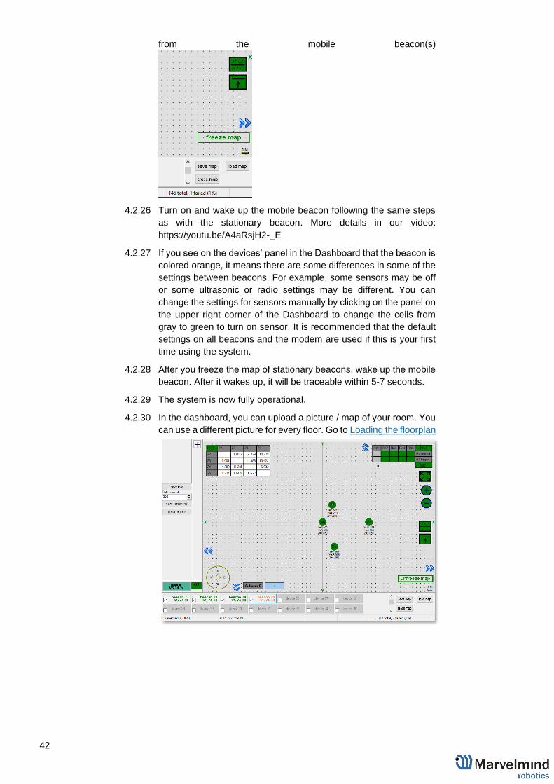
4.2.25 Freeze the map by clicking the button. Stationary beacons will stop
measuring relative distances and will be ready to measure distance
42
from the mobile beacon(s)
4.2.26 Turn on and wake up the mobile beacon following the same steps
as with the stationary beacon. More details in our video:
https://youtu.be/A4aRsjH2-_E
4.2.27 If you see on the devices’ panel in the Dashboard that the beacon is
colored orange, it means there are some differences in some of the
settings between beacons. For example, some sensors may be off
or some ultrasonic or radio settings may be different. You can
change the settings for sensors manually by clicking on the panel on
the upper right corner of the Dashboard to change the cells from
gray to green to turn on sensor. It is recommended that the default
settings on all beacons and the modem are used if this is your first
time using the system.
4.2.28 After you freeze the map of stationary beacons, wake up the mobile
beacon. After it wakes up, it will be traceable within 5-7 seconds.
4.2.29 The system is now fully operational.
4.2.30 In the dashboard, you can upload a picture / map of your room. You
can use a different picture for every floor. Go to Loading the floorplan

43
4.3 Starter Set NIA-01-3D
The steps below describe the very first time you set up the system. Mini-RX, HW v4.9 beacons and modem required.
Mini-RX beacons have different HW and SW from HW v4.9. Use Mini-beacon’s SW for Mini-beacons, HW v4.9’s SW for HW v4.9
4.3.1 Unpack the system. Take a look at a similar unpacking video of HW v4.9.
The videos have certain differences but the basic are the same:
https://youtu.be/sOce7B2_6Sk
4.3.2 Charge all the beacons using USB cable. Full charging takes about 1-2
hours
4.3.3 Turn the beacons on (Valid for HW v4.9. Mini-RX beacons are
permanently ON): Place DIP switches as shown on the picture below (For
HW v4.9)
4.3.4 Download SW Pack
4.3.5 Update all the beacons:
‒ Run the Dashboard and update the SW for all beacons and
modem using Dashboard => Firmware => Choose the file =>
Program

44
‒ If you see the message “Not found modem connection to
computer through USB” in the Dashboard or your PC does not
recognize beacons/modem, it usually means that the STM32
driver is not installed. To install the driver, download it through
the link in the top window in the Dashboard and run the
installation file, then click on the link under and install the driver
Make sure that that:
a. You are programming the modem’s SW to the modem and
the beacon’s SW to the beacon
b. You are using SW for 4.9, if you have HW v4.9; and you
have the SW from the same SW pack, i.e., the Dashboard
SW, modem SW, and beacon SW must be from the same
SW pack. Don’t mix SW releases
If SW flashed SUCESSUFLY, MOVE DIRECTLY TO 4.3.6. If you
have some problems with HEX programming, use DFU
programming:
DFU programming or SW uploading is used when HEX SW uploading in
the Dashboard cannot be used. For example, when you are updating
from a very old SW version or when the SW includes major changes to
the system and the only possible way to update the SW is via DFU
programming
- After the DFU SW upgrade, futures SW upgrades can be done
in a regular manner via the Dashboard
- To start programming, move the beacon’s DIP switch to the DFU
programming mode, as described in the paragraph on DIP
switch modes (DIP switch in Mini-RX and Mini-TX situated
inside the body. Carefully disassemble the body to access it)
- Download the latest SW package, unzip it, and select the proper
version of the SW for your HW and for your frequency variant.
Remember that for DFU programming, you should use DFU SW
(DfuSe), not Dashboard’s .hex file
- Download DfuSe
- Here you will find different versions of DfuSe. v3.0.4 or v3.0.5,
whichever works the best for your Windows: DfuSe v3.0.4 or
DfuSe v.3.0.5
DFU Programming:
- Put DIP switch into Power = ON, DFU = ON (DIP switch
in Mini-RX and Mini-TX situated inside the body. To
switch it, carefully disassemble the body)
- Connect the beacon via USB to your PC
- Run DfuSe
- Press the RESET button on your beacon
- In the upper left corner of the DfuSe program, you will see
a device connected in the DFU mode

45
- Choose the DFU driver (file) for the beacon
- Click the UPGRADE button
- After a couple of seconds, the DFU will be uploaded to the
beacon. Make sure it takes 1–3 seconds and does not
happen instantly. Otherwise, the SW has not been
uploaded correctly. If the DFU appears to upload
immediately, check the "Choose" button you used or
change the version of DfuSe SW you selected
- Move the DIP switch into Power = ON, DFU = OFF
- Start the Dashboard and press the RESET button on the
beacon
- Check SW on the beacon afterwards
- Everything should be OK with SW now. DFU programming
is complete
- Follow the same scenario for the modem:
- Here is the link for the modem DFU programming. The
steps are similar to those for beacon DFU programming
- After uploading DFU driver by DfuSe short circuit holes
temporarily as shown on the picture (for v4.9) press
UPGRADE button in the DfuSe program
- After a couple of seconds, the DFU will be uploaded to the
modem. Make sure it takes 1-3 seconds and does not
happen instantly. Otherwise, the SW has not been
uploaded correctly. If the DFU appears to upload
immediately, check the "Choose" button you used or
change the version of DfuSe SW to a different one
- Disconnect the short circuit
46
- Start the Dashboard and press RESET button
If you have uploaded the latest firmware for all of the boards, you can start to
activate the system:
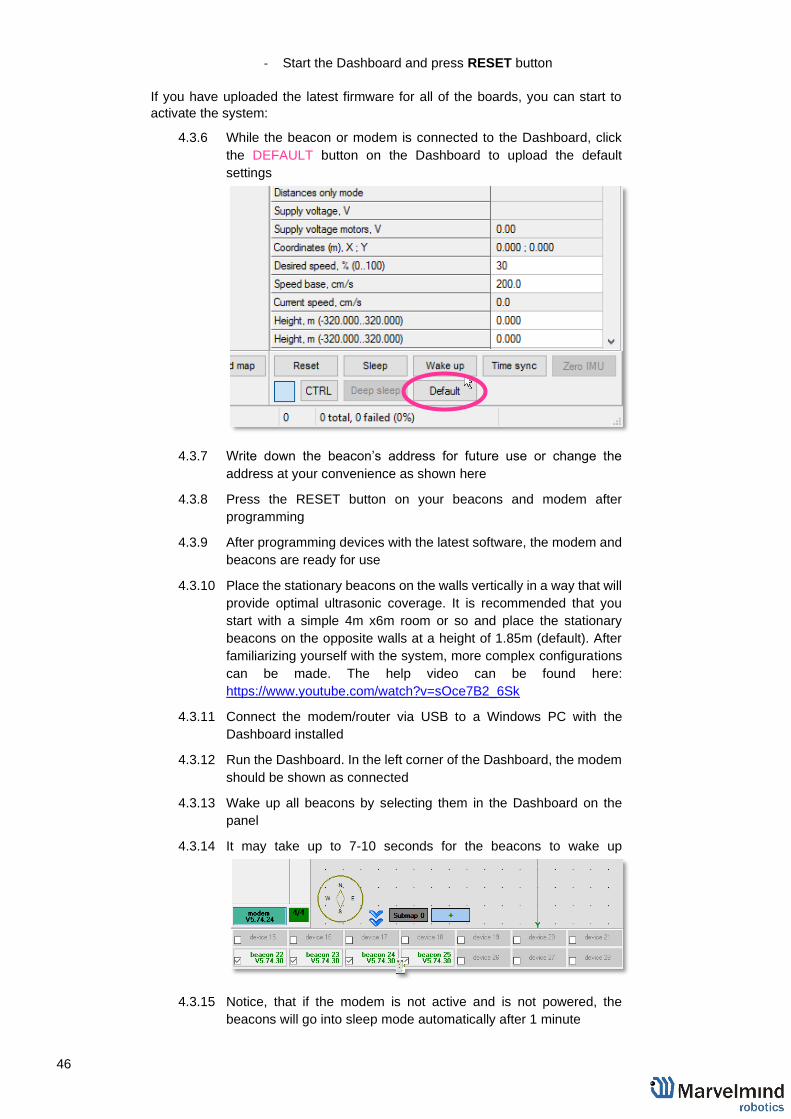
4.3.6 While the beacon or modem is connected to the Dashboard, click
the DEFAULT button on the Dashboard to upload the default
settings
4.3.7 Write down the beacon’s address for future use or change the
address at your convenience as shown here
4.3.8 Press the RESET button on your beacons and modem after
programming
4.3.9 After programming devices with the latest software, the modem and
beacons are ready for use
4.3.10 Place the stationary beacons on the walls vertically in a way that will
provide optimal ultrasonic coverage. It is recommended that you
start with a simple 4m x6m room or so and place the stationary
beacons on the opposite walls at a height of 1.85m (default). After
familiarizing yourself with the system, more complex configurations
can be made. The help video can be found here:
https://www.youtube.com/watch?v=sOce7B2_6Sk
4.3.11 Connect the modem/router via USB to a Windows PC with the
Dashboard installed
4.3.12 Run the Dashboard. In the left corner of the Dashboard, the modem
should be shown as connected
4.3.13 Wake up all beacons by selecting them in the Dashboard on the
panel
4.3.14 It may take up to 7-10 seconds for the beacons to wake up
4.3.15 Notice, that if the modem is not active and is not powered, the
beacons will go into sleep mode automatically after 1 minute
47
4.3.16 The system may run the frequency search if it is the very first time
you are waking up the beacons. If this step does not work,
disconnect the modem and connect that beacon again via USB.
Press the DEFAULT button in the Dashboard and the Read All
button to make sure that the radio settings are the default ones
4.3.17 Compare the radio settings on the modem and the radio settings on
the beacon. They must be the same
4.3.18 Now you can check the height position of the beacons, RSSI, radio
channel, threshold, etc. on the panel on the right corner of the
Dashboard
4.3.19 In the current version one modem supports 255 beacons. If you do
not see some of your connected beacons on the map, you may need
to scroll to find their addresses
4.3.20 Double click on the device to put it into sleep mode or wake it up
Only 4 stationary beacons may be in 1 submap. If you wake up
more beacons, create a new submap for them, otherwise it will
not be displayed on the map and in the table of distances.
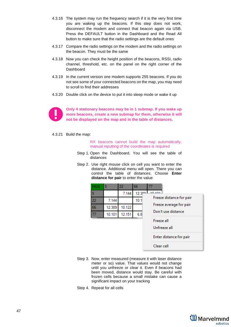
4.3.21 Build the map:
RX beacons cannot build the map automatically, manual inputting of the coordinates is required
Step 1. Open the Dashboard. You will see the table of distances
Step 2. Use right mouse click on cell you want to enter the distance. Additional menu will open. There you can control the table of distances. Choose Enter distance for pair to enter the value
Step 3. Now, enter measured (measure it with laser distance meter or so) value. That values would not change until you unfreeze or clear it. Even if beacons had been moved, distance would stay. Be careful with frozen cells because a small mistake can cause a significant impact on your tracking
Step 4. Repeat for all cells
48
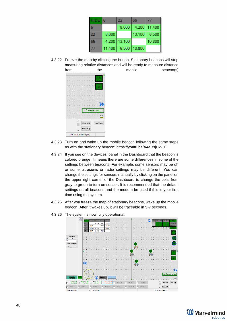
4.3.22 Freeze the map by clicking the button. Stationary beacons will stop
measuring relative distances and will be ready to measure distance
from the mobile beacon(s)
4.3.23 Turn on and wake up the mobile beacon following the same steps
as with the stationary beacon: https://youtu.be/A4aRsjH2-_E
4.3.24 If you see on the devices’ panel in the Dashboard that the beacon is
colored orange, it means there are some differences in some of the
settings between beacons. For example, some sensors may be off
or some ultrasonic or radio settings may be different. You can
change the settings for sensors manually by clicking on the panel on
the upper right corner of the Dashboard to change the cells from
gray to green to turn on sensor. It is recommended that the default
settings on all beacons and the modem be used if this is your first
time using the system.
4.3.25 After you freeze the map of stationary beacons, wake up the mobile
beacon. After it wakes up, it will be traceable in 5-7 seconds.
4.3.26 The system is now fully operational.

49
4.4 Starter Set NIA-SmallDrone
The steps below describe the very first time you set up the system. Mini-RX, Mini-TX beacons and modem required.
Mini-beacons have different HW and SW from HW v4.9. Use Mini-beacon’s SW for Mini-beacons, HW v4.9’s SW for HW v4.9
4.4.1 Unpack the system. Take a look at a similar unpacking video of HW v4.9.
The videos have certain differences but the basic are the same:
https://youtu.be/sOce7B2_6Sk
4.4.2 Charge all the beacons using USB cable. Full charging takes about 1-2
hours
4.4.3 Turn the beacons on (Valid for Mini-TX. Mini-RX beacons are
permanently ON): Place DIP switches as shown on the picture below (For
HW v4.9)
4.4.4 Download SW Pack
4.4.5 Update all the beacons:
‒ Run the Dashboard and update the SW for all beacons and
modem using Dashboard => Firmware => Choose the file =>
Program

50
‒ If you see the message “Not found modem connection to
computer through USB” in the Dashboard or your PC does not
recognize beacons/modem, it usually means that the STM32
driver is not installed. To install the driver, download it through
the link in the top window in the Dashboard and run the
installation file, then click on the link under and install the driver
Make sure that that:
c. You are programming the modem’s SW to the modem and
the beacon’s SW to the beacon
d. You are using SW for Mini-TX, if you have Mini-TX; and
you have the SW from the same SW pack, i.e., the
Dashboard SW, modem SW, and beacon SW must be
from the same SW pack. Don’t mix SW releases
If SW flashed SUCESSUFLY, MOVE DIRECTLY TO 4.4.6. If you
have some problems with HEX programming, use DFU
programming:
DFU programming or SW uploading is used when HEX SW uploading in
the Dashboard cannot be used. For example, when you are updating
from a very old SW version or when the SW includes major changes to
the system and the only possible way to update the SW is via DFU
programming
- After the DFU SW upgrade, futures SW upgrades can be done
in a regular manner via the Dashboard
- To start programming, move the beacon’s DIP switch to the DFU
programming mode, as described in the paragraph on DIP
switch modes (DIP switch in Mini-RX and Mini-TX situated
inside the body. Carefully disassemble the body to access it)
- Download the latest SW package, unzip it, and select the proper
version of the SW for your HW and for your frequency variant.
Remember that for DFU programming, you should use DFU SW
(DfuSe), not Dashboard’s .hex file
- Download DfuSe
- Here you will find different versions of DfuSe. v3.0.4 or v3.0.5,
whichever works the best for your Windows: DfuSe v3.0.4 or
DfuSe v.3.0.5
DFU Programming:
- Put DIP switch into Power = ON, DFU = ON (DIP switch
in Mini-RX and Mini-TX situated inside the body. To
switch it, carefully disassemble the body)
- Connect the beacon via USB to your PC
- Run DfuSe
- Press the RESET button on your beacon
- In the upper left corner of the DfuSe program, you will see
a device connected in the DFU mode

51
- Choose the DFU driver (file) for the beacon
- Click the UPGRADE button
- After a couple of seconds, the DFU will be uploaded to the
beacon. Make sure it takes 1–3 seconds and does not
happen instantly. Otherwise, the SW has not been
uploaded correctly. If the DFU appears to upload
immediately, check the "Choose" button you used or
change the version of DfuSe SW you selected
- Move the DIP switch into Power = ON, DFU = OFF
- Start the Dashboard and press the RESET button on the
beacon
- Check SW on the beacon afterwards
- Everything should be OK with SW now. DFU programming
is complete
- Follow the same scenario for the modem:
- Here is the link for the modem DFU programming. The
steps are similar to those for beacon DFU programming
- After uploading DFU driver by DfuSe short circuit holes
temporarily as shown on the picture (for v4.9) press
UPGRADE button in the DfuSe program
- After a couple of seconds, the DFU will be uploaded to the
modem. Make sure it takes 1-3 seconds and does not
happen instantly. Otherwise, the SW has not been
uploaded correctly. If the DFU appears to upload
immediately, check the "Choose" button you used or
change the version of DfuSe SW to a different one
- Disconnect the short circuit

52
- Start the Dashboard and press RESET button
If you have uploaded the latest firmware for all of the boards, you can start to
activate the system:
4.4.6 While the beacon or modem is connected to the Dashboard, click
the DEFAULT button on the Dashboard to upload the default
settings
4.4.7 Write down the beacon’s address for future use or change the
address at your convenience as shown here
4.4.8 Press the RESET button on your beacons and modem after
programming
4.4.9 After programming devices with the latest software, the modem and
beacons are ready for use
4.4.10 Place the stationary beacons on the walls vertically in a way that will
provide optimal ultrasonic coverage. It is recommended that you
start with a simple 4m x6m room or so and place the stationary
beacons on the opposite walls at a height of 1.85m (default). After
familiarizing yourself with the system, more complex configurations
can be made. The help video can be found here:
https://www.youtube.com/watch?v=sOce7B2_6Sk
4.4.11 Connect the modem/router via USB to a Windows PC with the
Dashboard installed
4.4.12 Run the Dashboard. In the left corner of the Dashboard, the modem
should be shown as connected
4.4.13 Wake up all beacons by selecting them in the Dashboard on the
panel
4.4.14 It may take up to 7-10 seconds for the beacons to wake up
4.4.15 Notice, that if the modem is not active and is not powered, the
beacons will go into sleep mode automatically after 1 minute

53
4.4.16 The system may run the frequency search if it is the very first time
you are waking up the beacons. If this step does not work,
disconnect the modem and connect that beacon again via USB.
Press the DEFAULT button in the Dashboard and the Read All
button to make sure that the radio settings are the default ones
4.4.17 Compare the radio settings on the modem and the radio settings on
the beacon. They must be the same
4.4.18 Now you can check the height position of the beacons, RSSI, radio
channel, threshold, etc. on the panel on the right corner of the
Dashboard
4.4.19 In the current version one modem supports 255 beacons. If you do
not see some of your connected beacons on the map, you may need
to scroll to find their addresses
4.4.20 Double click on the device to put it into sleep mode or wake it up
Only 4 stationary beacons may be in 1 submap. If you wake up
more beacons, create a new submap for them, otherwise it will
not be displayed on the map and in the table of distances.
4.4.21 Build the map:
RX beacons cannot build the map automatically, manual inputting of the coordinates is required
Step 5. Open the Dashboard. You will see the table of distances
Step 6. Use right mouse click on cell you want to enter the distance. Additional menu will open. There you can control the table of distances. Choose Enter distance for pair to enter the value
Step 7. Now, enter measured (measure it with laser distance meter or so) value. That values would not change until you unfreeze or clear it. Even if beacons had been moved, distance would stay. Be careful with frozen cells because a small mistake can cause a significant impact on your tracking
Step 8. Repeat for all cells

54
4.4.22 Freeze the map by clicking the button. Stationary beacons will stop
measuring relative distances and will be ready to measure distance
from the mobile beacon(s)
4.4.23 Turn on and wake up the mobile beacon following the same steps
as with the stationary beacon: https://youtu.be/A4aRsjH2-_E
4.4.24 If you see on the devices’ panel in the Dashboard that the beacon is
colored orange, it means there are some differences in some of the
settings between beacons. For example, some sensors may be off
or some ultrasonic or radio settings may be different. You can
change the settings for sensors manually by clicking on the panel on
the upper right corner of the Dashboard to change the cells from
gray to green to turn on sensor. It is recommended that the default
settings on all beacons and the modem be used if this is your first
time using the system.
4.4.25 After you freeze the map of stationary beacons, wake up the mobile
beacon. After it wakes up, it will be traceable in 5-7 seconds.
4.4.26 The system is now fully operational.

55
4.5 Starter Set NIA-02-2D
The steps below describe the very first time you set up the system. Mini-RX, Mini-TX beacons and modem required.
Mini-beacons have different HW and SW from HW v4.9. Use Mini-beacon’s SW for Mini-beacons, HW v4.9’s SW for HW v4.9, etc.
4.5.1 Unpack the system. Take a look at a similar unpacking video of HW v4.9.
The videos have certain differences but the basic are the same:
https://youtu.be/sOce7B2_6Sk
4.5.2 Charge all the beacons using USB cable. Full charging takes about 1-2
hours
4.5.3 Turn the beacons on (Valid for Mini-TX. Mini-RX beacons are
permanently ON): Place DIP switches as shown on the picture below (For
HW v4.9)
4.5.4 Download SW Pack
4.5.5 Update all the beacons:
‒ Run the Dashboard and update the SW for all beacons and
modem using Dashboard => Firmware => Choose the file =>

56
Program
‒ If you see the message “Not found modem connection to
computer through USB” in the Dashboard or your PC does not
recognize beacons/modem, it usually means that the STM32
driver is not installed. To install the driver, download it through
the link in the top window in the Dashboard and run the
installation file, then click on the link under and install the driver
Make sure that that:
e. You are programming the modem’s SW to the modem and
the beacon’s SW to the beacon
f. You are using SW for Mini-TX, if you have Mini-TX; and
you have the SW from the same SW pack, i.e., the
Dashboard SW, modem SW, and beacon SW must be
from the same SW pack. Don’t mix SW releases
If SW flashed SUCESSUFLY, MOVE DIRECTLY TO 4.5.6. If you
have some problems with HEX programming, use DFU
programming:
DFU programming or SW uploading is used when HEX SW uploading in
the Dashboard cannot be used. For example, when you are updating
from a very old SW version or when the SW includes major changes to
the system and the only possible way to update the SW is via DFU
programming
- After the DFU SW upgrade, futures SW upgrades can be done
in a regular manner via the Dashboard
- To start programming, move the beacon’s DIP switch to the DFU
programming mode, as described in the paragraph on DIP
switch modes (DIP switch in Mini-RX and Mini-TX situated
inside the body. Carefully disassemble the body to access it)
- Download the latest SW package, unzip it, and select the proper
version of the SW for your HW and for your frequency variant.
Remember that for DFU programming, you should use DFU SW
(DfuSe), not Dashboard’s .hex file
- Download DfuSe
- Here you will find different versions of DfuSe. v3.0.4 or v3.0.5,
whichever works the best for your Windows: DfuSe v3.0.4 or
DfuSe v.3.0.5
DFU Programming:

57
- Put DIP switch into Power = ON, DFU = ON (DIP switch
in Mini-RX and Mini-TX situated inside the body. To
switch it, carefully disassemble the body)
- Connect the beacon via USB to your PC
- Run DfuSe
- Press the RESET button on your beacon
- In the upper left corner of the DfuSe program, you will see
a device connected in the DFU mode
- Choose the DFU driver (file) for the beacon
- Click the UPGRADE button
- After a couple of seconds, the DFU will be uploaded to the
beacon. Make sure it takes 1–3 seconds and does not
happen instantly. Otherwise, the SW has not been
uploaded correctly. If the DFU appears to upload
immediately, check the "Choose" button you used or
change the version of DfuSe SW you selected
- Move the DIP switch into Power = ON, DFU = OFF
- Start the Dashboard and press the RESET button on the
beacon
- Check SW on the beacon afterwards
- Everything should be OK with SW now. DFU programming
is complete
- Follow the same scenario for the modem:
- Here is the link for the modem DFU programming. The
steps are similar to those for beacon DFU programming

58
- After uploading DFU driver by DfuSe short circuit holes
temporarily as shown on the picture (for v4.9) press
UPGRADE button in the DfuSe program
- After a couple of seconds, the DFU will be uploaded to the
modem. Make sure it takes 1-3 seconds and does not
happen instantly. Otherwise, the SW has not been
uploaded correctly. If the DFU appears to upload
immediately, check the "Choose" button you used or
change the version of DfuSe SW to a different one
- Disconnect the short circuit
- Start the Dashboard and press RESET button
If you have uploaded the latest firmware for all of the boards, you can start to
activate the system:
4.5.6 While the beacon or modem is connected to the Dashboard, click
the DEFAULT button on the Dashboard to upload the default
settings
4.5.7 Write down the beacon’s address for future use or change the
address at your convenience as shown here
4.5.8 Press the RESET button on your beacons and modem after
programming
4.5.9 After programming devices with the latest software, the modem and
beacons are ready for use
4.5.10 Place the stationary beacons on the walls vertically in a way that will
provide optimal ultrasonic coverage. It is recommended that you
start with a simple 4m x6m room or so and place the stationary
beacons on the opposite walls at a height of 1.85m (default). After
familiarizing yourself with the system, more complex configurations
can be made. The help video can be found here:
https://www.youtube.com/watch?v=sOce7B2_6Sk
4.5.11 Connect the modem/router via USB to a Windows PC with the
Dashboard installed
4.5.12 Run the Dashboard. In the left corner of the Dashboard, the modem
should be shown as connected
4.5.13 Wake up all beacons by selecting them in the Dashboard on the
panel

59
4.5.14 It may take up to 7-10 seconds for the beacons to wake up
4.5.15 Notice, that if the modem is not active and is not powered, the
beacons will go into sleep mode automatically after 1 minute
4.5.16 The system may run the frequency search if it is the very first time
you are waking up the beacons. If this step does not work,
disconnect the modem and connect that beacon again via USB.
Press the DEFAULT button in the Dashboard and the Read All
button to make sure that the radio settings are the default ones
4.5.17 Compare the radio settings on the modem and the radio settings on
the beacon. They must be the same
4.5.18 Now you can check the height position of the beacons, RSSI, radio
channel, threshold, etc. on the panel on the right corner of the
Dashboard
4.5.19 In the current version one modem supports 255 beacons. If you do
not see some of your connected beacons on the map, you may need
to scroll to find their addresses
4.5.20 Double click on the device to put it into sleep mode or wake it up
Only 4 stationary beacons may be in 1 submap. If you wake up
more beacons, create a new submap for them, otherwise it will
not be displayed on the map and in the table of distances.
4.5.21 Build the map:
RX beacons cannot build the map automatically, manual inputting of the coordinates is required
Step 9. Open the Dashboard. You will see the table of distances
Step 10. Use right mouse click on cell you want to enter the distance. Additional menu will open. There you can control the table of distances. Choose Enter distance for pair to enter the value

60
Step 11. Now, enter measured (measure it with laser distance meter or so) value. That values would not change until you unfreeze or clear it. Even if beacons had been moved, distance would stay. Be careful with frozen cells because a small mistake can cause a significant impact on your tracking
Step 12. Repeat for all cells
4.5.22 Freeze the map by clicking the button. Stationary beacons will stop
measuring relative distances and will be ready to measure distance
from the mobile beacon(s)
4.5.23 Turn on and wake up the mobile beacon following the same steps
as with the stationary beacon: https://youtu.be/A4aRsjH2-_E
4.5.24 If you see on the devices’ panel in the Dashboard that the beacon is
colored orange, it means there are some differences in some of the
settings between beacons. For example, some sensors may be off
or some ultrasonic or radio settings may be different. You can
change the settings for sensors manually by clicking on the panel on
the upper right corner of the Dashboard to change the cells from
gray to green to turn on sensor. It is recommended that the default

61
settings on all beacons and the modem be used if this is your first
time using the system.
4.5.25 After you freeze the map of stationary beacons, wake up the mobile
beacon. After it wakes up, it will be traceable in 5-7 seconds.
4.5.26 The system is now fully operational.

62
4.6 Starter Set Industrial-NIA-01
The steps below describe the first set up of the system.
This is a Non-Inverse Architecture. You can find the description and comparison of architectures here.
Pay attention: Industrial beacons have different HW and SW from HW v4.9. It has different connectors, reset and DFU activation. Read more on Industrial beacon page.
Industrial beacons have no battery, use power supply cable.
Use Industrial beacon’s SW for Industrial beacons, v4.9 for v4.9.
4.6.1 Unpack the system. Take a look at the similar unpacking video of HW
v4.9. They are different, but have some similar basics:
https://youtu.be/sOce7B2_6Sk
4.6.2 You do not have to charge Industrial beacons; they have no battery.
4.6.3 You do not have to turn it on - Industrial beacons are permanently ON.
4.6.4 Download SW Pack
4.6.5 Update all the beacons:
‒ Run the Dashboard and update the SW for all beacons and
modem using Dashboard => Firmware => Choose the file =>
Program
‒ If you see the message “Not found modem connection to
computer through USB” in the Dashboard or your PC does not
recognize beacons/modem, it usually means that the STM32
driver is not installed. To install the driver, download it with link
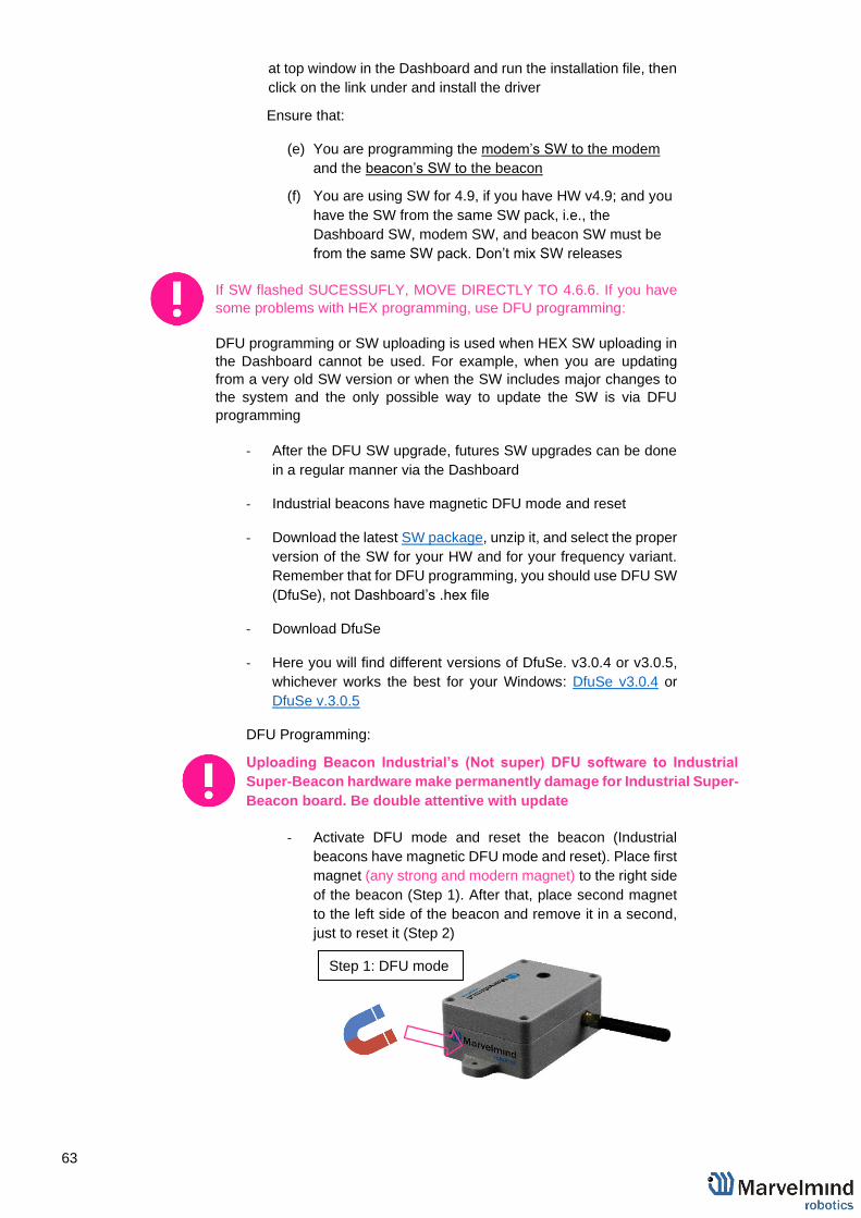
63
at top window in the Dashboard and run the installation file, then
click on the link under and install the driver
Ensure that:
(e) You are programming the modem’s SW to the modem
and the beacon’s SW to the beacon
(f) You are using SW for 4.9, if you have HW v4.9; and you
have the SW from the same SW pack, i.e., the
Dashboard SW, modem SW, and beacon SW must be
from the same SW pack. Don’t mix SW releases
If SW flashed SUCESSUFLY, MOVE DIRECTLY TO 4.6.6. If you have
some problems with HEX programming, use DFU programming:
DFU programming or SW uploading is used when HEX SW uploading in
the Dashboard cannot be used. For example, when you are updating
from a very old SW version or when the SW includes major changes to
the system and the only possible way to update the SW is via DFU
programming
- After the DFU SW upgrade, futures SW upgrades can be done
in a regular manner via the Dashboard
- Industrial beacons have magnetic DFU mode and reset
- Download the latest SW package, unzip it, and select the proper
version of the SW for your HW and for your frequency variant.
Remember that for DFU programming, you should use DFU SW
(DfuSe), not Dashboard’s .hex file
- Download DfuSe
- Here you will find different versions of DfuSe. v3.0.4 or v3.0.5,
whichever works the best for your Windows: DfuSe v3.0.4 or
DfuSe v.3.0.5
DFU Programming:
Uploading Beacon Industrial’s (Not super) DFU software to Industrial
Super-Beacon hardware make permanently damage for Industrial Super-
Beacon board. Be double attentive with update
- Activate DFU mode and reset the beacon (Industrial
beacons have magnetic DFU mode and reset). Place first
magnet (any strong and modern magnet) to the right side
of the beacon (Step 1). After that, place second magnet
to the left side of the beacon and remove it in a second,
just to reset it (Step 2)
Step 1: DFU mode
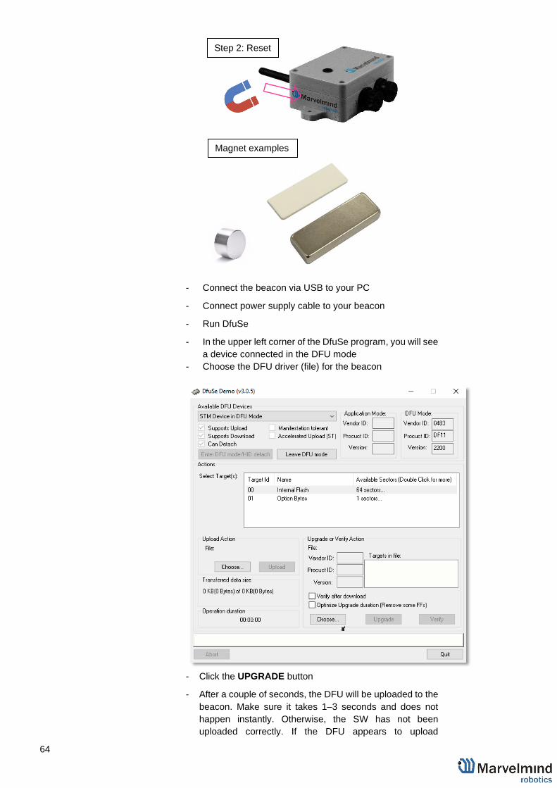
64
- Connect the beacon via USB to your PC
- Connect power supply cable to your beacon
- Run DfuSe
- In the upper left corner of the DfuSe program, you will see
a device connected in the DFU mode
- Choose the DFU driver (file) for the beacon
- Click the UPGRADE button
- After a couple of seconds, the DFU will be uploaded to the
beacon. Make sure it takes 1–3 seconds and does not
happen instantly. Otherwise, the SW has not been
uploaded correctly. If the DFU appears to upload
Step 2: Reset
Magnet examples

65
immediately, check the "Choose" button you used or
change the version of DfuSe SW you selected
- Start the Dashboard
- Reset the beacon again
- Check SW on the beacon afterwards
- Everything should be OK with SW now. DFU programming
is complete.
DFU Programming for the modem:
- Here is the link for the modem DFU programming. The
steps are similar to those for beacon DFU programming.
- After uploading DFU driver by DfuSe short circuit holes
temporarily as shown on the picture (for v4.9) press
UPGRADE button in the DfuSe program.
- After a couple of seconds, the DFU will be uploaded to the
modem. Make sure it takes 1-3 seconds and does not
happen instantly. Otherwise, the SW has not been
uploaded correctly. If the DFU appears to upload
immediately, check the "Choose" button you used or
change the version of DfuSe SW to a different one.
- Disconnect the short circuit.
- Start the Dashboard and press RESET button.
If you have uploaded the latest firmware for all of the boards, you can start to
activate the system:
4.6.6 While the beacon or modem is connected to the Dashboard, click
the DEFAULT button on the Dashboard to upload the default
settings
4.6.7 Write down the beacon’s address for future use or change the
address at your convenience as shown here
4.6.8 Press the RESET (Industrial beacons have magnetic re button on
your beacons and modem after programming
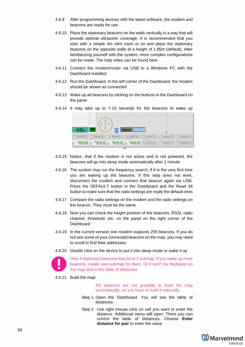
66
4.6.9 After programming devices with the latest software, the modem and
beacons are ready for use
4.6.10 Place the stationary beacons on the walls vertically in a way that will
provide optimal ultrasonic coverage. It is recommended that you
start with a simple 4m x6m room or so and place the stationary
beacons on the opposite walls at a height of 1.85m (default). After
familiarizing yourself with the system, more complex configurations
can be made. The help video can be found here
4.6.11 Connect the modem/router via USB to a Windows PC with the
Dashboard installed
4.6.12 Run the Dashboard. In the left corner of the Dashboard, the modem
should be shown as connected
4.6.13 Wake up all beacons by clicking on the buttons in the Dashboard on
the panel
4.6.14 It may take up to 7-10 seconds for the beacons to wake up
4.6.15 Notice, that if the modem is not active and is not powered, the
beacons will go into sleep mode automatically after 1 minute
4.6.16 The system may run the frequency search, if it is the very first time
you are waking up the beacons. If this step does not work,
disconnect the modem and connect that beacon again via USB.
Press the DEFAULT button in the Dashboard and the Read All
button to make sure that the radio settings are really the default ones
4.6.17 Compare the radio settings on the modem and the radio settings on
the beacon. They must be the same
4.6.18 Now you can check the height position of the beacons, RSSI, radio
channel, threshold, etc. on the panel on the right corner of the
Dashboard
4.6.19 In the current version one modem supports 255 beacons. If you do
not see some of your connected beacons on the map, you may need
to scroll to find their addresses
4.6.20 Double click on the device to put it into sleep mode or wake it up
Only 4 stationary beacons may be in 1 submap. If you wake up more
beacons, create new submap for them. Or it won’t be displayed on
the map and in the table of distances
4.6.21 Build the map:
RX beacons are not possible to build the map automatically, so you have to build it manually
Step 1. Open the Dashboard. You will see the table of distances
Step 2. Use right mouse click on cell you want to enter the distance. Additional menu will open. There you can control the table of distances. Choose Enter distance for pair to enter the value

67
Step 3. Now, enter measured (measure it with laser distance meter or so) value. That values would not change until you unfreeze or clear it. Even if beacons had been moved, distance would stay. Be careful with frozen cells because a small mistake can cause a huge impact on your tracking
Step 4. Repeat for all cells
4.6.22 Freeze the map by clicking the button. Stationary beacons will stop
measuring relative distances and will be ready to measure distance
from the mobile beacon(s)
4.6.23 Turn on and wake up the mobile beacon following the same steps
as with the stationary beacon: https://youtu.be/A4aRsjH2-_E
4.6.24 If you see on the devices’ panel in the Dashboard that the beacon is
colored orange, it means there are some differences in some of the
settings between beacons. For example, some sensors may be off
or some ultrasonic or radio settings may be different. You can
change the settings for sensors manually by clicking on the panel on
the upper right corner of the Dashboard to change the cells from
gray to green to turn on sensor. It is recommended that the default

68
settings on all beacons and the modem be used if this is your first
time using the system
4.6.25 After you freeze the map of stationary beacons, wake up the mobile
beacon. After it wakes up, it will be traceable within 5-7 seconds
4.6.26 The system is now fully operational

69
5. Setting up the system (IA)
5.1 Starter Set IA-01-2D
The steps below describe the very first time you set up of the system. Mini-RX-beacon, HW v4.9 beacons and modem required.
This is Inverse Architecture. Beacons HW v4.9 should have different frequencies. Use IA Software ONLY.
You can’t just switch HW v4.9 beacon to another frequency, it is HW depended
Ultrasonic can't be changed to default. You must check the frequency on the white sticker
5.1.1 Unpack the system. Take a look at the similar unpacking video of HW
v4.9. They are different, but have some similar basics:
https://youtu.be/sOce7B2_6Sk
5.1.2 Charge all the beacons using USB cable. Full charging takes about 1-2
hours
5.1.3 Turn the beacons on (DIP switch in Mini-RX and Mini-TX situated inside
the body. To switch it, carefully disassemble the body): Place DIP
switches as shown on the picture below
5.1.4 Download SW Pack
5.1.5 Update all the beacons
‒ You need Inverse Architecture SW (go to
marvelmind_SW_xxx_xx_xx\Software_ia)
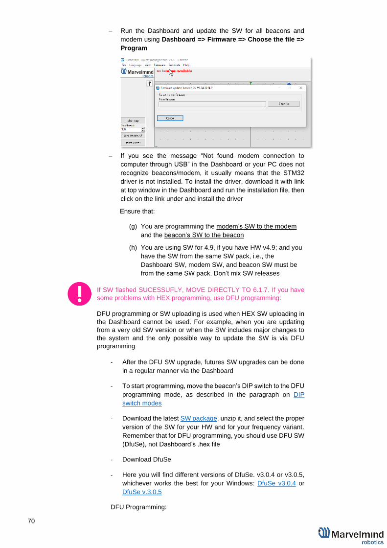
70
‒ Run the Dashboard and update the SW for all beacons and
modem using Dashboard => Firmware => Choose the file =>
Program
‒ If you see the message “Not found modem connection to
computer through USB” in the Dashboard or your PC does not
recognize beacons/modem, it usually means that the STM32
driver is not installed. To install the driver, download it with link
at top window in the Dashboard and run the installation file, then
click on the link under and install the driver
Ensure that:
(g) You are programming the modem’s SW to the modem
and the beacon’s SW to the beacon
(h) You are using SW for 4.9, if you have HW v4.9; and you
have the SW from the same SW pack, i.e., the
Dashboard SW, modem SW, and beacon SW must be
from the same SW pack. Don’t mix SW releases
If SW flashed SUCESSUFLY, MOVE DIRECTLY TO 6.1.7. If you have
some problems with HEX programming, use DFU programming:
DFU programming or SW uploading is used when HEX SW uploading in
the Dashboard cannot be used. For example, when you are updating
from a very old SW version or when the SW includes major changes to
the system and the only possible way to update the SW is via DFU
programming
- After the DFU SW upgrade, futures SW upgrades can be done
in a regular manner via the Dashboard
- To start programming, move the beacon’s DIP switch to the DFU
programming mode, as described in the paragraph on DIP
switch modes
- Download the latest SW package, unzip it, and select the proper
version of the SW for your HW and for your frequency variant.
Remember that for DFU programming, you should use DFU SW
(DfuSe), not Dashboard’s .hex file
- Download DfuSe
- Here you will find different versions of DfuSe. v3.0.4 or v3.0.5,
whichever works the best for your Windows: DfuSe v3.0.4 or
DfuSe v.3.0.5
DFU Programming:

71
- Put DIP switch into Power = ON, DFU = ON (DIP switch
in Mini-RX and Mini-TX situated inside the body. To
switch it, carefully disassemble the body).
- Connect the beacon via USB to your PC.
- Run DfuSe.
- Press the RESET button on your beacon.
- In the upper left corner of the DfuSe program, you will see
a device connected in the DFU mode.
- Choose the DFU driver (file) for the beacon.
- Click the UPGRADE button
- After a couple of seconds, the DFU will be uploaded to the
beacon. Make sure it takes 1–3 seconds and does not
happen instantly. Otherwise, the SW has not been
uploaded correctly. If the DFU appears to upload
immediately, check the "Choose" button you used or
change the version of DfuSe SW you selected
- Move the DIP switch into Power = ON, DFU = OFF
- Start the Dashboard and press the RESET button on the
beacon
- Check SW on the beacon afterwards
- Everything should be OK with SW now. DFU programming
is complete
Follow the same scenario for the modem:
- Here is the link for the modem DFU programming. The
steps are similar to those for beacon DFU programming.

72
- After uploading DFU driver by DfuSe short circuit holes
temporarily as shown on the picture (for v4.9) press
UPGRADE button in the DfuSe program.
- After a couple of seconds, the DFU will be uploaded to the
modem. Make sure it takes 1-3 seconds and does not
happen immediately. Otherwise, the SW has not uploaded
correctly. If the DFU appears to upload immediately, check
the "Choose" button you used or change the version of
DfuSe SW to a different one.
- Disconnect the short circuit.
- Start the Dashboard and press RESET button
If you have uploaded the latest firmware for all the boards, you can start to activate
the system:
5.1.6 While the beacon or modem is connected to the Dashboard, click the
DEFAULT button on the Dashboard to upload the default settings
5.1.7 Write down the beacon’s address for future use or change the address
at your convenience as shown here.
5.1.8 Press the RESET button on your beacons and modem after
programming.
5.1.9 After programming devices with the latest software, the modem and
beacons are ready for use.
5.1.10 Place the stationary beacons on the walls vertically in a way that will
provide optimal ultrasonic coverage. It is recommended that you start
with a simple 4x6m room or so and place the stationary beacons on the
opposite walls at the same height.
5.1.11 Connect the modem/router via USB to a Windows PC with the
Dashboard installed.
5.1.12 Run the Dashboard. In the left corner of the Dashboard, the modem
should be shown as connected.
5.1.13 Wake up all beacons by clicking on the buttons in the Dashboard on the
panel.

73
5.1.14 It may take up to 7-10 seconds for the beacons to wake up.
5.1.15 Notice, that if the modem is not active and is not powered, the beacons
will go into sleep mode automatically after 1 minute.
5.1.16 The system may run the frequency search, if it is the very first time you
are waking up the beacons. If this step does not work, disconnect the
modem and connect that beacon again via USB. Press the DEFAULT
button in the Dashboard and the Read All button to make sure that the
radio settings are really the default ones.
5.1.17 Compare the radio settings on the modem and the radio settings on the
beacon. They must be the same.
5.1.18 Now you can check the height position of the beacons, RSSI, radio
channel, threshold, etc. on the panel on the right corner of the
Dashboard.
5.1.19 It is possible to manage 255 beacons simultaneously. In current version
one modem supports 255 beacons. If you do not see some of your
connected beacons on the map, you may need to scroll to find their
addresses.
Only 4 stationary beacons may be in 1 submap. If you wake up
more beacons, create new submap for them. Or it won’t be
displayed on the map and in the table of distances.
5.1.20 Build the map:
Beacons with different frequencies are not able to build the map automatically, so you have to build it manually
Step 1. Open the Dashboard. You will see the table of distances.
Step 2. Use right mouse click on cell you want to enter the distance. Additional menu will open. There you can control the table of distances. Choose Enter distance for pair to enter the value.

74
Step 3. Now, enter measured (measure it with laser distance meter or so) value. That values would not change until you unfreeze or clear it. Even if beacons had been moved, distance would stay. Be careful with frozen cells because a small mistake can cause a huge impact on your tracking.
Step 4. Repeat for all cells.
5.1.21 Freeze submap and by clicking the button. Stationary beacons will stop
measuring relative distances and will be ready to measure distance from
the mobile beacon(s).
5.1.22 Turn on and wake up the mobile beacon following the same steps as with
the stationary beacon: https://youtu.be/A4aRsjH2-_E
5.1.23 If you see on the devices’ panel in the Dashboard that the beacon is
colored orange, it means there are some differences in some of the
settings between beacons. For example, some sensors may be off or
some ultrasonic or radio settings may be different. You can change the
settings for sensors manually by clicking on the panel on the upper right
corner of the Dashboard to change the cells from gray to green to turn
on sensor. It is recommended that the default settings on all beacons and
the modem be used if this is your first time using the system.
5.1.24 After you freeze the map of stationary beacons, wake up the mobile
beacon. After it wakes up, it will be traceable in 5-7 seconds.
freeze submap

75
5.1.25 The system is now fully operational.

76
5.2 Starter Set IA-02-3D
The steps below describe the very first time you set up of the system. Mini-RX-beacon, HW v4.9 beacons and modem required.
This is Inverse Architecture. Beacons HW v4.9 should have different frequencies. Use IA Software ONLY.
You can’t just switch HW v4.9 beacon to another frequency, it is HW depended
Ultrasonic can't be changed to default. You must check the frequency on the white sticker
5.2.1 Unpack the system. Take a look at the similar unpacking video of HW
v4.9. They are different, but have some similar basics:
https://youtu.be/sOce7B2_6Sk
5.2.2 Charge all the beacons using USB cable. Full charging takes about 1-2
hours
5.2.3 Turn the beacons on (DIP switch in Mini-RX and Mini-TX situated inside
the body. To switch it, carefully disassemble the body): Place DIP
switches as shown on the picture below
5.2.4 Download SW Pack
5.2.5 Update all the beacons
‒ You need Inverse Architecture SW (go to
marvelmind_SW_xxx_xx_xx\Software_ia)

77
‒ Run the Dashboard and update the SW for all beacons and
modem using Dashboard => Firmware => Choose the file =>
Program
‒ If you see the message “Not found modem connection to
computer through USB” in the Dashboard or your PC does not
recognize beacons/modem, it usually means that the STM32
driver is not installed. To install the driver, download it with link
at top window in the Dashboard and run the installation file, then
click on the link under and install the driver
Ensure that:
(i) You are programming the modem’s SW to the modem
and the beacon’s SW to the beacon
(j) You are using SW for 4.9, if you have HW v4.9; and you
have the SW from the same SW pack, i.e., the
Dashboard SW, modem SW, and beacon SW must be
from the same SW pack. Don’t mix SW releases
If SW flashed SUCESSUFLY, MOVE DIRECTLY TO 5.2.6. If you have
some problems with HEX programming, use DFU programming:
DFU programming or SW uploading is used when HEX SW uploading in
the Dashboard cannot be used. For example, when you are updating
from a very old SW version or when the SW includes major changes to
the system and the only possible way to update the SW is via DFU
programming
- After the DFU SW upgrade, futures SW upgrades can be done
in a regular manner via the Dashboard
- To start programming, move the beacon’s DIP switch to the DFU
programming mode, as described in the paragraph on DIP
switch modes
- Download the latest SW package, unzip it, and select the proper
version of the SW for your HW and for your frequency variant.
Remember that for DFU programming, you should use DFU SW
(DfuSe), not Dashboard’s .hex file
- Download DfuSe
- Here you will find different versions of DfuSe. v3.0.4 or v3.0.5,
whichever works the best for your Windows: DfuSe v3.0.4 or
DfuSe v.3.0.5
DFU Programming:

78
- Put DIP switch into Power = ON, DFU = ON (DIP switch
in Mini-RX and Mini-TX situated inside the body. To
switch it, carefully disassemble the body).
- Connect the beacon via USB to your PC.
- Run DfuSe.
- Press the RESET button on your beacon.
- In the upper left corner of the DfuSe program, you will see
a device connected in the DFU mode.
- Choose the DFU driver (file) for the beacon.
- Click the UPGRADE button
- After a couple of seconds, the DFU will be uploaded to the
beacon. Make sure it takes 1–3 seconds and does not
happen instantly. Otherwise, the SW has not been
uploaded correctly. If the DFU appears to upload
immediately, check the "Choose" button you used or
change the version of DfuSe SW you selected
- Move the DIP switch into Power = ON, DFU = OFF
- Start the Dashboard and press the RESET button on the
beacon
- Check SW on the beacon afterwards
- Everything should be OK with SW now. DFU programming
is complete
Follow the same scenario for the modem:
- Here is the link for the modem DFU programming. The
steps are similar to those for beacon DFU programming.

79
- After uploading DFU driver by DfuSe short circuit holes
temporarily as shown on the picture (for v4.9) press
UPGRADE button in the DfuSe program.
- After a couple of seconds, the DFU will be uploaded to the
modem. Make sure it takes 1-3 seconds and does not
happen immediately. Otherwise, the SW has not uploaded
correctly. If the DFU appears to upload immediately, check
the "Choose" button you used or change the version of
DfuSe SW to a different one.
- Disconnect the short circuit.
- Start the Dashboard and press RESET button
If you have uploaded the latest firmware for all of the boards, you can start to activate
the system:
5.2.6 While the beacon or modem is connected to the Dashboard, click the
DEFAULT button on the Dashboard to upload the default settings
5.2.7 Write down the beacon’s address for future use or change the address
at your convenience as shown here.
5.2.8 Press the RESET button on your beacons and modem after
programming.
5.2.9 After programming devices with the latest software, the modem and
beacons are ready for use.
5.2.10 Place the stationary beacons on the walls vertically in a way that will
provide optimal ultrasonic coverage. It is recommended that you start
with a simple 4x6m room or so and place the stationary beacons on the
opposite walls at the same height.
5.2.11 Connect the modem/router via USB to a Windows PC with the
Dashboard installed.
5.2.12 Run the Dashboard. In the left corner of the Dashboard, the modem
should be shown as connected.
5.2.13 Wake up all beacons by clicking on the buttons in the Dashboard on the
panel.

80
5.2.14 It may take up to 7-10 seconds for the beacons to wake up.
5.2.15 Notice, that if the modem is not active and is not powered, the beacons
will go into sleep mode automatically after 1 minute.
5.2.16 The system may run the frequency search, if it is the very first time you
are waking up the beacons. If this step does not work, disconnect the
modem and connect that beacon again via USB. Press the DEFAULT
button in the Dashboard and the Read All button to make sure that the
radio settings are really the default ones.
5.2.17 Compare the radio settings on the modem and the radio settings on the
beacon. They must be the same.
5.2.18 Now you can check the height position of the beacons, RSSI, radio
channel, threshold, etc. on the panel on the right corner of the
Dashboard.
5.2.19 It is possible to manage 255 beacons simultaneously. In current version
one modem supports 255 beacons. If you do not see some of your
connected beacons on the map, you may need to scroll to find their
addresses.
Only 4 stationary beacons may be in 1 submap. If you wake up more
beacons, create new submap for them. Or it won’t be displayed on
the map and in the table of distances.
5.2.20 Build the map:
Beacons with different frequencies are not able to build the map automatically, so you have to build it manually
Step 5. Open the Dashboard. You will see the table of distances.
Step 6. Use right mouse click on cell you want to enter the distance. Additional menu will open. There you can control the table of distances. Choose Enter distance for pair to enter the value.

81
Step 7. Now, enter measured (measure it with laser distance meter or so) value. That values would not change until you unfreeze or clear it. Even if beacons had been moved, distance would stay. Be careful with frozen cells because a small mistake can cause a huge impact on your tracking.
Step 8. Repeat for all cells.
5.2.21 Freeze submap and by clicking the button. Stationary beacons will stop
measuring relative distances and will be ready to measure distance from
the mobile beacon(s).
5.2.22 Turn on and wake up the mobile beacon following the same steps as with
the stationary beacon: https://youtu.be/A4aRsjH2-_E
5.2.23 If you see on the devices’ panel in the Dashboard that the beacon is
colored orange, it means there are some differences in some of the
settings between beacons. For example, some sensors may be off or
some ultrasonic or radio settings may be different. You can change the
settings for sensors manually by clicking on the panel on the upper right
corner of the Dashboard to change the cells from gray to green to turn
on sensor. It is recommended that the default settings on all beacons and
the modem be used if this is your first time using the system.
5.2.24 After you freeze the map of stationary beacons, wake up the mobile
beacon. After it wakes up, it will be traceable in 5-7 seconds.
freeze submap

82
5.2.25 The system is now fully operational.

83
6. Dashboard menu and parameters
6.1 Dashboard general view
- This picture shows the Dashboard’s general interface and items’ positions
Modem/beacon’s
settings bar
Modem/beacon’s
quick control panel
Visualization
window
Table of
distances
Visualization
settings
Devices list
Map settings
Modem
Ceiling and
mirroring buttons

84
6.2 Table of distances
Table of distances shows the measured distance between all beacons. The map and its graphical
visualization depends on distances, which is a very important part of the system.
There are two ways of measuring:
1) Measuring by ultrasound (automatic)
2) Measuring by user (manual)
*Measuring by ultrasound is impossible for Mini-RX beacons
*In noisy cases and cases with long distances it is better to use manual input
1) Measuring by ultrasound:
- In most cases, the system builds the table of distances automatically. If everything is
good, there would be figures in cells, they would be changing a little; the color of each
cell would be white
- If color differs, check the colors’ definitions (next page) and solve the problem
- Freeze the map only if cells are white
2) Measuring by user (necessary for Mini-RX beacons and noisy cases):
- Use manual input if table of distances didn’t build. It may happen if environment is
very noisy, or distances are very huge
- In that case, cells’ color would be green
- Be careful with figures because a small mistake in the values will cause mistakes in
location
How to freeze/enter distance manually:
Step 1. Open the Dashboard. You will see the table of distances
Step 2. Use right mouse click on cell you want to freeze/enter. Additional menu will open. There you can control the table of distances. Choose Freeze distance for pair to freeze it

85
Step 3. Now, cells are frozen. That values would not change until you unfreeze it. Even if beacons had been moved, distance would stay. Be careful with frozen cells because a small mistake can cause a huge impact on your tracking
Step 4. Repeat for all cells
- White means that everything is good, you can freeze the map
- Green means frozen distance, you can freeze the map, but be careful with values
- Yellow means that something seems to be wrong, check distances and sensors before freezing
- Red means some critical misses, DO NOT freeze the map. Manually measure and enter distances

86
6.3 Devices list
Devices list contains information about all the beacons in the system. It also allows to search, add
and delete it.
Devices in this section are divided into two types:
1) Stationary beacon (beacon)
2) Mobile beacon (hedge)
- Devices list allows user to manage devices
- Use double click to put beacon into sleep mode
1) Stationary beacon (beacon)
- Press right mouse button and additional menu will open
- There you can:
- Remove beacon from current submap
- Remove beacon from the whole network
- Manually setup coordinates (x, y, z)
2) Mobile beacon (hedge)
- Press right mouse button and additional menu will open
- There you can:
- Remove beacon from the network
- Setup movement path
- Upload zones (allowed and denied)
- Manually setup coordinates (x, y, z)

87
6.4 Visualization settings
Visualization settings window has some functions to control visualization process:
- Clear map – clear all movement path
- Dots timeout – time of path’s existence (Video: Help: Dots timeout)
- Dots size mode – size of dots
- Save screenshot – files saves to Dashboard’s folder/screenshots
- Freeze screen – The map freeze, no updates of the path

88
6.5 Map Settings
Map Settings offer some helpful tools:
- Save map – saves map as .ini file into Dashboard folder/maps
- Load map – loads map from .ini format file
- Erase map – erases map and clears it

89
6.6 Modem/beacon’s quick control panel
Control panel allows user to interact with devices. It can work with one device, or with all devices in
the system.
List of functions:
Reset – Resets device
Sleep – Send device asleep (battery economy mode)
Wake up – Wakes up device (from sleeping mode)
Default – Drops all device’s settings to factory default
Time sync – Sends time from your PC to hedgehog (for stream it out via UART)
Additional Ctrl feature:
To apply action to all beacons in the system, use Ctrl + left mouse click on button.
Applicable only for buttons that turn bold while Ctrl is pressed.

90
6.7 CEILLING and MIRRORING buttons on the Dashboard
- The MIRRORING button allows the map to be display as a mirror reflection
- The CEILING button shows where the mobile beacon is located with respect to
the stationary beacons
- When the arrow points up, it means that the mobile beacon is below the stationary
beacons
- When the arrow points down, it means that the mobile beacon is above the
stationary beacons

91
6.8 Modem Settings
This bar allows user to adjust devices very precisely. It contains a lot of parameters for advanced usage
Modem Settings
Location update rate settings: 1/20Hz – 16Hz+.
Notice that real update rate may be limited by distances
between beacons or radio profile
TBD
Internal filter. More – faster objects can be tracked. Less –
better filtering against location jumps
Set of power saving features. May not work in all settings or
all SW releases. Keep disabled, if unsure
Averaging between location update measurements. More
value – less location jitter, but higher latency
Filter of distances (as opposed to filter of locations). More –
better filtering, but may be too conservative and “kill” good
measurements
Keep Enabled normally. Switch to cm for backward
compatibility
If map is frozen, new beacons will be accepted in the map,
if enabled
TBD
Unique processor ID for each device (beacon or modem)

92
TBD
Power supply voltage of the device 5V+-0.2V is OK
N/A
Time from the latest reset
Measured temperature of the processor’s crystal
Strength of the radio signal from modem to beacons and
vice versa. Maintain in the range of -25dBm to -80..-
90dBm. Higher value - may overload. Lower – lost packets
Chosen working band
Exact working frequency
Logical address of the device. Keep 2..255 for beacons.
Address
Pre-selected channel – one of the radio channels for
communication between modem and beacons
If enabled, beacons will be seen as green dots on the map.
If disabled, they won’t be seen at all
Enable or disable visibility of Service Areas (Zones)
Make Service Zones active or not active

93
Advanced settings
TBD
Enabling will allow direction along with location:
TBD
TBD
TBD

94
Parameters of radio
Selected radio profile with a set of profile settings.
Choose between 38kbps (better range and interference
immunity, but slower); 153kbps – balanced; and 500kbps –
the fastest, but the lowest radio range and least immune to
interference
Logical address of the device. Distinguish of beacon from
another
One of a predefined radio frequency channels
Modulation – a part of the radio profile. Only for advanced
users
Only for advanced users
Only for advanced users
Only for advanced users
Real carrier frequency

95
Radio profile settings. No need to change manually. Only
for advanced users
Radio profile settings. No need to change manually. Only
for advanced users
Radio profile settings. No need to change manually. Only
for advanced users
Radio profile settings. No need to change manually. Only
for advanced users
Radio profile settings. No need to change manually. Only
for advanced users
Radio profile settings. No need to change manually. Only
for advanced users
Radio profile settings. No need to change manually. Only
for advanced users
Radio profile settings. No need to change manually. Only
for advanced users

96
Beacon’s settings
Unique CPU ID
Enable for mobile beacon and disable for stationary beacon
TBD
TBD
Measured voltage of internal battery
NA
Height – must be set for stationary beacons.
Must also be set for mobile beacons in 1D or 2D modes
Time from the latest reset
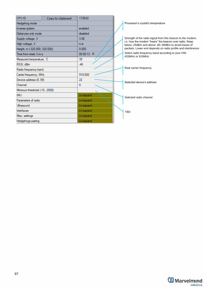
97
Processor’s crystal’s temperature
Strength of the radio signal from this beacon to the modem,
i.e. how the modem “hears” the beacon over radio. Keep
below -25dBm and above -80..90dBm to avoid losses of
packets. Lower end depends on radio profile and interference
Select radio frequency band according to your HW:
433MHz or 915MHz
Real carrier frequency
Selected device’s address
Selected radio channel
TBD

98
IMU
Calibration settings of embedded IMU: X shift
Calibration settings of embedded IMU: Y shift
Calibration settings of embedded IMU: Z shift
Calibration settings of embedded IMU: X scale
Calibration settings of embedded IMU: Y scale
Calibration settings of embedded IMU: Z scale

99
Parameters of radio
Radio profile that is linked with many radio settings below.
Helps to set them at once by choosing the profile. See
similar in modem for more info
Device address – shall be set for each beacon different
under one modem
One of the pre-selected frequency channels
Radio profile settings. No need to change manually. Only
for advanced users
Radio profile settings. No need to change manually. Only
for advanced users
Radio profile settings. No need to change manually. Only
for advanced users
Radio profile settings. No need to change manually. Only
for advanced users
Real carrier frequency

100
Radio profile settings. No need to change manually. Only
for advanced users
Radio profile settings. No need to change manually. Only
for advanced users
Radio profile settings. No need to change manually. Only
for advanced users
Radio profile settings. No need to change manually. Only
for advanced users
Radio profile settings. No need to change manually. Only
for advanced users
Radio profile settings. No need to change manually. Only
for advanced users
Radio profile settings. No need to change manually. Only
for advanced users
Radio profile settings. No need to change manually. Only
for advanced users

101
Ultrasound
TX-RX – regular mode. Use it. The rest - internal
TBD
Power saving features. If not sure, keep default
Power saving features. If not sure, keep default
TBD
Frequency of ultrasonic pulses – set according to your HW
50% - default. 1% … 99% lower strength of ultrasonic.
Keep default
Number of ultrasonic pulses the TX beacon emits. More –
stronger, but longer echo. For small distances – 1-10
periods. 20-30 – for 10-20 meters. For 20+ m – 50 periods
Internal settings
Automatic or manual gain control.
Manual can be useful in special conditions: too high
external audio noise, for example
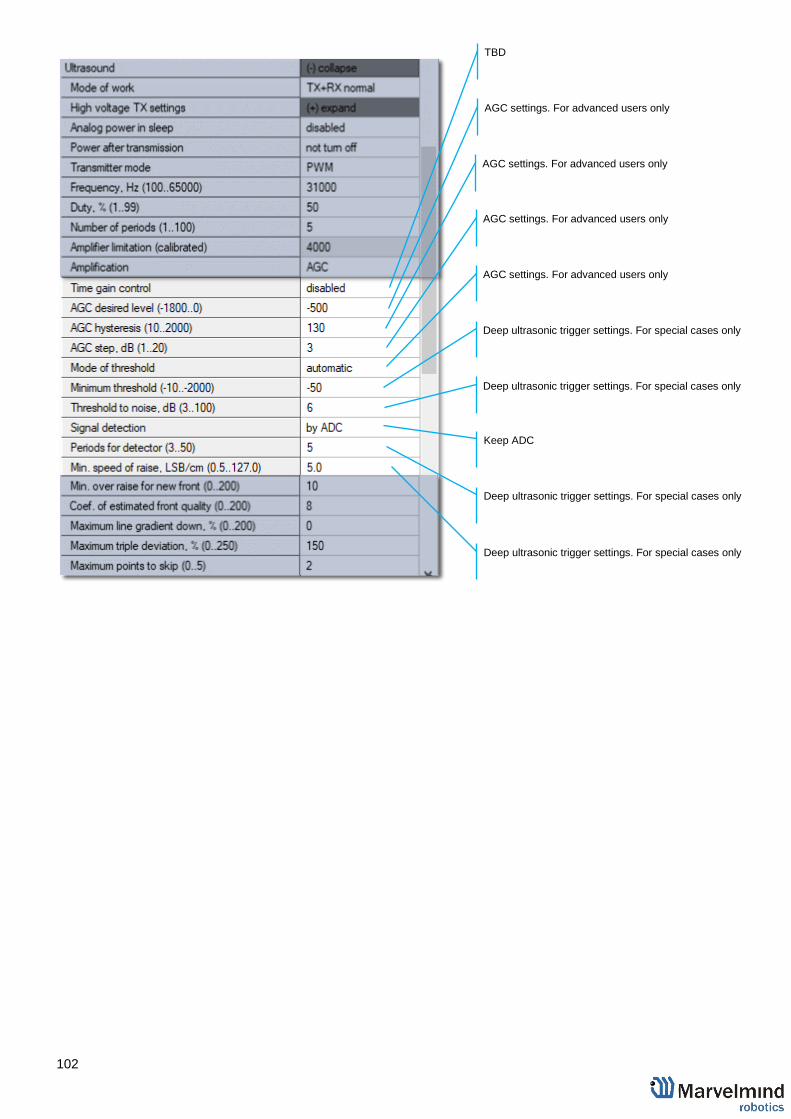
102
TBD
AGC settings. For advanced users only
AGC settings. For advanced users only
AGC settings. For advanced users only
AGC settings. For advanced users only
Deep ultrasonic trigger settings. For special cases only
Deep ultrasonic trigger settings. For special cases only
Keep ADC
Deep ultrasonic trigger settings. For special cases only
Deep ultrasonic trigger settings. For special cases only

103
Deep ultrasonic trigger settings. For special cases only
Deep ultrasonic trigger settings. For special cases only
Deep ultrasonic trigger settings. For special cases only
Deep ultrasonic trigger settings. For special cases only
Deep ultrasonic trigger settings. For special cases only
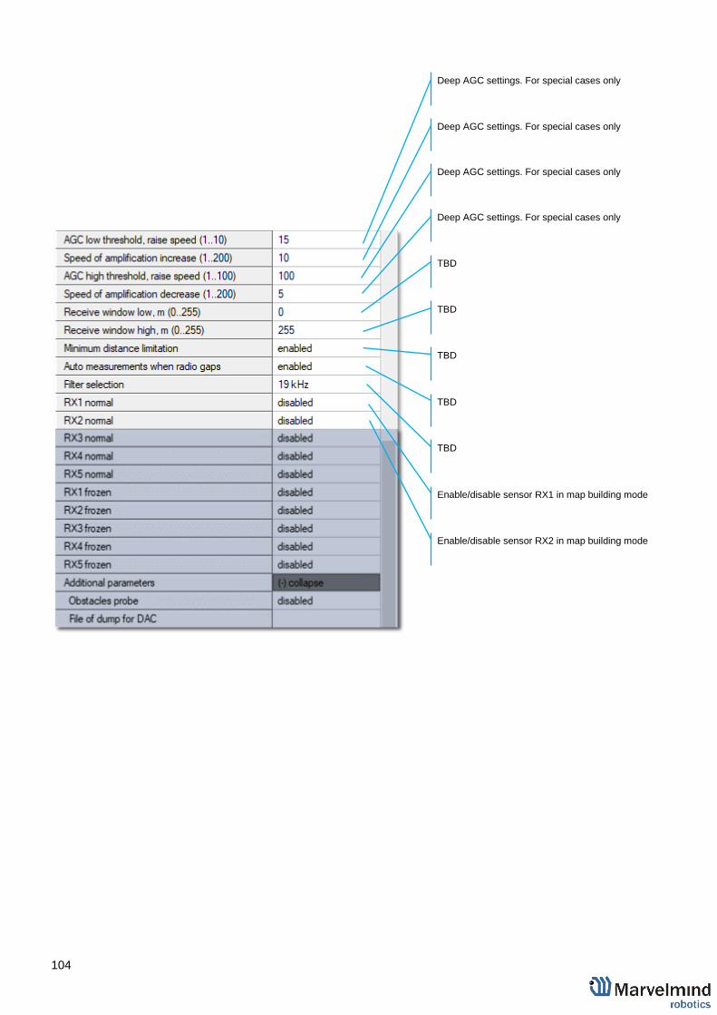
104
Deep AGC settings. For special cases only
Deep AGC settings. For special cases only
Deep AGC settings. For special cases only
Deep AGC settings. For special cases only
TBD
TBD
TBD
TBD
TBD
Enable/disable sensor RX1 in map building mode
Enable/disable sensor RX2 in map building mode

105
Enable/disable sensor RX3 in map building mode
Enable/disable sensor RX4 in map building mode
Enable/disable sensor RX5 in map building mode
Enable/disable sensor RX1 in map frozen/regular work
mode
Enable/disable sensor RX2 in map frozen/regular work
mode
Enable/disable sensor RX3 in map frozen/regular work
mode
Enable/disable sensor RX4 in map frozen/regular work
mode
Enable/disable sensor RX5 in map frozen/regular work
mode
TBD
TBD
TBD

106
Interfaces
Georeferencing
Misc. settings
Hedgehogs pairing
Enable or disable receiving IMU+ultrasonic sensor fusion
data with IMU update rate (100Hz)
Enable or disable receiving raw IMU data with IMU update
rate (100Hz)
TBD
Type of protocol
Speed of UART in hedgehog mode
The same as with modem
The same as with modem
Timeout sleep settings
Enable for Paired Beacons feature:
https://youtu.be/aBWUALT3WTQ
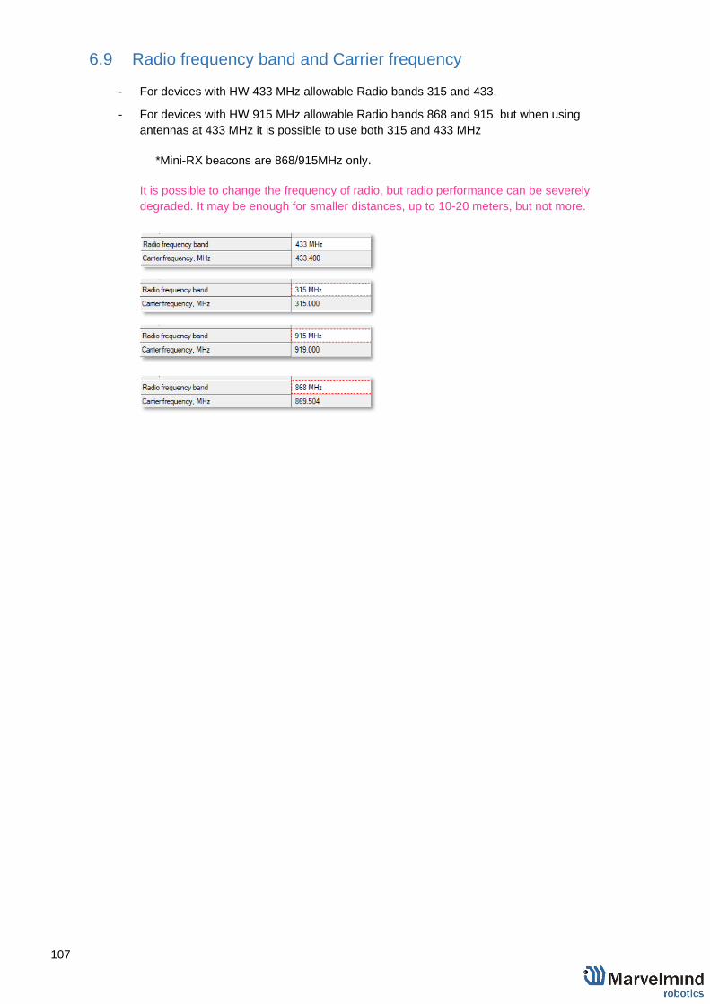
107
6.9 Radio frequency band and Carrier frequency
- For devices with HW 433 MHz allowable Radio bands 315 and 433,
- For devices with HW 915 MHz allowable Radio bands 868 and 915, but when using
antennas at 433 MHz it is possible to use both 315 and 433 MHz
*Mini-RX beacons are 868/915MHz only.
It is possible to change the frequency of radio, but radio performance can be severely
degraded. It may be enough for smaller distances, up to 10-20 meters, but not more.

108
6.10 Different hedgehog colors in the Dashboard
You can choose any color for your hedge, but it still has some permanent colors, which inform you
about some tracking issues:
- Blue - normal mode and confident tracking
- Orange - system provides the best location data possible, but confidence is
lower than blue
- - lost radio packets
- – weak ultrasonic coverage

109
6.11 Different stationary beacons’ colors in the Dashboard
Stationary beacons v4.9 can have different ultrasonic frequency. Because of that, they have
different colors to make it easy to distinguish it:
- 19KHz beacon
- 25KHz beacon
- 31KHz beacon
- 37KHz beacon
- 45KHz beacon

110
7. SW feature/settings descriptions
7.1 Licenses
We added the licenses system. Now, you can order some additional features. It is not
available in the basic Dashboard version, but you can easily purchase it if necessary. You
can see the list on Marvelmind.com -> Products
To order:
- Go to Marvelmind.com -> Products
- Choose features which you want to get (e.g. MMSW0001: 100Hz NMEA0183)
- Make an order.
- Pay for the feature (via PayPal or other methods).
- Order the feature via the Dashboard by providing modem's CPU ID or send us
email with the modem's CPU ID:
- Open Dashboard SW
- Connect modem to the Dashboard via USB
- Go to Licenses → View/activate licenses
- Choose the licenses which you have purchased.
- Press Order licenses.
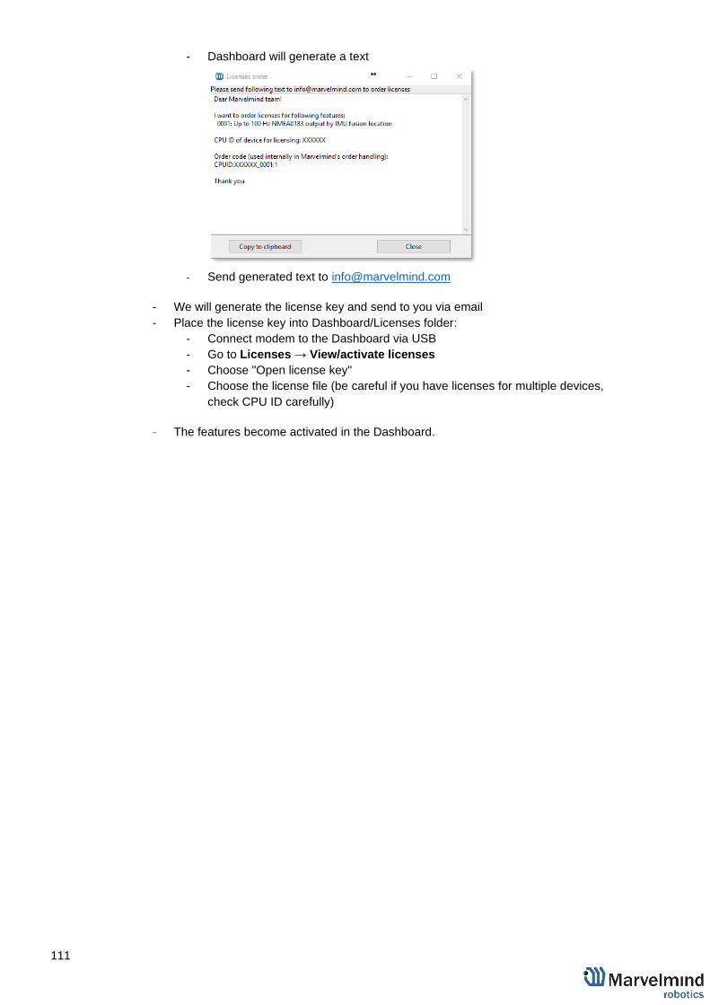
111
- Dashboard will generate a text
- Send generated text to [email protected]
- We will generate the license key and send to you via email
- Place the license key into Dashboard/Licenses folder:
- Connect modem to the Dashboard via USB
- Go to Licenses → View/activate licenses
- Choose "Open license key"
- Choose the license file (be careful if you have licenses for multiple devices,
check CPU ID carefully)
- The features become activated in the Dashboard.
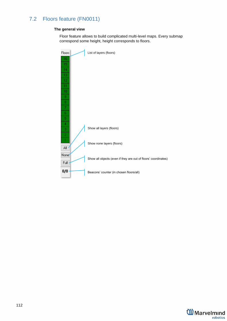
112
7.2 Floors feature (FN0011)
The general view
Floor feature allows to build complicated multi-level maps. Every submap
correspond some height, height corresponds to floors.
Show all layers (floors)
Show none layers (floors)
Show all objects (even if they are out of floors’ coordinates)
List of layers (floors)
Beacons’ counter (in chosen floors/all)

113
Floor Settings
- Every floor has its own adjustable height and its own floor plan
- Use right mouse button on the floor area to see an additional menu. There
you can change floor’s height. You can also insert your floorplan for that
floor (.png, .jpeg, .bmp, .tiff)
Floor 4 and 5 are enabled:

114
Floor 5 is enabled:
Floor 4 is enabled:
Loading the Floorplan (Substrate)
- Right mouse button click on the floor -> Load floorplan -> Choose file
(.png, .jpeg, .bmp, .tiff).
- When the picture is loaded, you can drag the beacons to the points where
they are actually located. After dragging two beacons, the picture with
beacons will be combined in scale.

115
7.3 Submap Settings
Every submap has its own settings. To correspond your submap to a certain floor you
need to adjust the height:
- To open that settings, use left mouse button on the submap icon -
- Change Submap Z shift value

116
7.4 Axis rotation feature (FN0002)
General view
Axis extension allows user to rotate the map. There are 90° gaps between
views. It helps in case of multifloor tracking, when it is important to have a side
view.
There are 3 directions of view:
- To change view, click on the icon
Example of views:
Y, X
X, Y

117
Z, X

118
7.5 Vertical submaps feature (FN0003)
Vertical submap is a new feature for drone flights or some other specific cases. It
gives the user an opportunity to get solid Z data for vertical movement
Example: The drone flight
How to build vertical submap for stable Z:
8.5.1 For this configuration you need 6 stationary beacons

119
8.5.2 Place 4 beacons on the ground, facing each other. (make a square,
where the edge points are beacons, looking in the center)
8.5.3 Place two beacons high on a wall
8.5.4 Turn on RX4 only for beacons on the ground and RX4 and RX2 for
beacons on the wall
8.5.5 Build the first submap (horizontal) consisting of all ground beacons
8.5.6 Change Limitation distance to manual and input the value in the
submap’s settings
8.5.7 Freeze and lock it
8.5.8 Build the second submap (vertical) horizontally consisting of two wall
beacons and two ground beacons (neighboring with wall beacons)
8.5.9 Now, freeze it
8.5.10 Press axis rotation button
8.5.11 Click on the axis you want to rotate your submap along (when you
point the cursor on the axis, it became visible and pink-colored)
8.5.12 Enter the corner value (90° usually)

120
8.5.13 Choose submap 2 and enable “Only for Z coordinates” mode
8.5.14 Change Limitation distance value
8.5.15 Change views and check the map
8.5.16 Wake up mobile beacon
8.5.17 Track

121
7.6 Handover Zones Setting
User must setup handover zones between submaps to guarantee handover
quality for complex maps with multi-floor and similar.
How to setup handover zones:
‒ Choose any submap
‒ Use Alt + Left mouse click on the other submap’s service zone
border (neighboring)
‒ Now, neighboring service zones are colored with green (dark
green for chosen submap and light green for neighboring
submaps)
Alt + Left mouse click

122
7.7 Submaps feature (FN0004)
2D submap example
Submaps is a very powerful feature that allows building large maps (full business
center, factory, warehouse with total area of 10,000..300,000 or more) based on
smaller submaps (30..1000m2).
A submap is a part of the map. It includes a subset of used beacons covering part
of the navigation area. Current version of Marvelmind system can include up to 10
submaps. Please also check our help video.
Follow these steps:
Step 1. Choose the beacons which will be added to certain submap0…submapN
Step 2. Connect the modem and put all the beacons into sleeping mode
Step 3. Click “erase map” button for removing some current settings of beacons and submaps
Step 4. Wake up all the beacons which should be served by submap0
Step 5. Wait a little for map will automatically build. If needed use mirroring function
Step 6. Freeze the submap
Step 7. Add the new submap by clicking “+” button. New submap is automatically chosen as active
Step 8. Wake up the beacons which should be served by submap1. By default, all the beacons are served by the last unfrozen submap
Step 9. If the new submap should include beacons which are at the moment served by previous submaps (intersected submaps) click on each beacon, then right-mouse-click=>Add to current submap
Step 10. If the new submap has 1 or 2 common beacons with previous submaps, it will settle as a part of the already built map. Two common beacons give a tight binding. If there is only one common beacon it’s possible to drag and drop the submap. If submaps do not have common beacons it is needed to drag and drop the selected submap using the mouse and holding down the CTRL button. Rotation of submap can be executed by using the mouse wheel
Step 11. Align submaps using M1/M2 parameter
Step 12. Set Service Zones for each submap
Nose shows direction of the
tracking zone

123
Starting submaps
- Hedgehogs do not belong to any submap and can move between sub-map areas.
Hedgehogs can be served by multiple submaps at the same time. By default, the
map consists of a single submap (Submap0)
- After adding new beacons to the system (waking them up), they appear in the first
not frozen submap or in Submap0 if all beacons are frozen
- Pressing the “+” button will add a new empty submap to the system
- Press the button with the submap number (Submap0, Submap1 etc.) - select the corresponding submap
- In this state, if the modem button is pushed, the list of parameters on the
right side represents some of the parameters of the selected submap, for
example, “Starting beacon trilateration,” “Starting set of beacons,” etc.
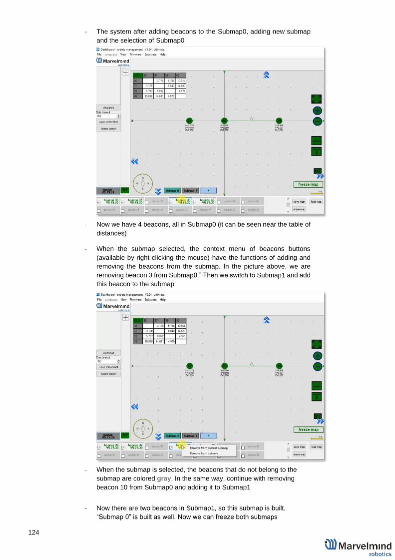
124
- The system after adding beacons to the Submap0, adding new submap
and the selection of Submap0
- Now we have 4 beacons, all in Submap0 (it can be seen near the table of
distances)
- When the submap selected, the context menu of beacons buttons
(available by right clicking the mouse) have the functions of adding and
removing the beacons from the submap. In the picture above, we are
removing beacon 3 from Submap0.” Then we switch to Submap1 and add
this beacon to the submap
- When the submap is selected, the beacons that do not belong to the
submap are colored gray. In the same way, continue with removing
beacon 10 from Submap0 and adding it to Submap1
- Now there are two beacons in Submap1, so this submap is built.
“Submap 0” is built as well. Now we can freeze both submaps

125
- Pressing the “freeze map” button when the submap is selected will only
freeze the selected submap. Pressing the “freeze map” button when the
modem button is selected will freeze all submaps.
- Now we have two good submaps, but they are not correctly located
relative to each other. On the right side exist the parameters of shift and
rotation for the selected submap; they can be filled in by hands. But a
more user friendly way is to drag and drop the selected submap using the
mouse and holding down the CTRL button.
- Rotation of submap can be executed by using the mouse wheel. The
mirroring button can also be used; it affects only submaps that are
selected
- After some movement, rotation, and mirroring of submaps, we can locate
the submaps close to their real relative location
- Now the system is ready to use; we can wake up and track the mobile
hedgehog
- In some cases, the hedgehog can be lost between the submaps if this
area is not covered by any of the submaps.

126
- Submaps can be removed from the system by using the context menu of
the submap selection button (available with a right mouse click) M1/M2
parameter used for precise superposing submaps which do not have
common beacons. This means that submaps cannot be aligned
automatically
To align submaps:
1. Build the system like in previous instruction
2. Put M2 in mode on by clicking the icon. Place the hedgehog near
the boundary between two submaps. You will see 2 orange
hedgehogs blinking, this is how the hedge is seen in two submaps
3. To align submaps correctly (CTRL + scroll/drag) against each
other, until the orange mobile beacons are fully overlapped
4. Replace hedgehog to 1 or 2 points and repeat replacing submap
for better superposing

127
- The next step is to set Service zones, which are zones where tracking is
possible. If a mobile beacon is out of a service zone it cannot be tracked.
If you built a complicated map, you have to make service zones correctly.
Service zones must be crossing in order to provide correct and glide
tracking.
How to create a service zone:
- Choose submap (click on the submap icon)
- Use SHIFT + Left mouse button on the map to create point.
- Use SHIFT + Left mouse button on the point to delete it.
- Put points around submap, move them to provide service area for current
submap. Service areas will cross each other. If hedgehogs get lost
between two submaps expand the service area.

128
7.8 Paired beacons (FN0005)
- Two hedgehogs can be paired and work together as a single beacon without
update rate reduction.
- Moreover, each beacon streams out in this mode not only its own location, but
direction where the pair is facing. This feature hugely simplifies autonomous
driving and flight. Here is an updated protocol with the changes.
- Please, also check our help video.
Follow these steps:
1. Wake up stationary beacons and freeze the map
2. Wake up two hedgehogs which were pre-installed on robot/copter/drone
3. Choose one beacon and go to “Pairing mode” parameter and activate
4. Write the “Address of paired beacon”, means number of the beacon,
current selected hedgehog is paired with
5. Now choose location against center in parameters relatively the second
beacon
6. Go to “Base of the pair” parameter and write actual distance between
paired hedgehogs. Do the same for 2nd hedgehog.

129
7.9 Map settings
Save Map/Load Map feature and buttons are active now. You can build a very complex map with submaps and save all settings for the map, submaps, and all beacons including their ultrasonic gain, triggers, etc.

130
7.10 Hedge color change (FN0006)
If you have multiple mobile beacons you can give each one its own color to make them recognizable on the map
How to change hedgehog color:
‒ Right mouse button click on the hedge in the list of devices -> Setup color

131
‒ Choose any color which suits you and press OK
‒ Now, the hedgehog and its tracking path will be colored

132
7.11 Payload streaming (FN0007)
- Mobile beacon streaming user payload to modem. See the table with speed
vs. payload
- All measurements were made with update rate setting 16 Hz. Real update rate
is limited by distance, radio profile and payload data size.
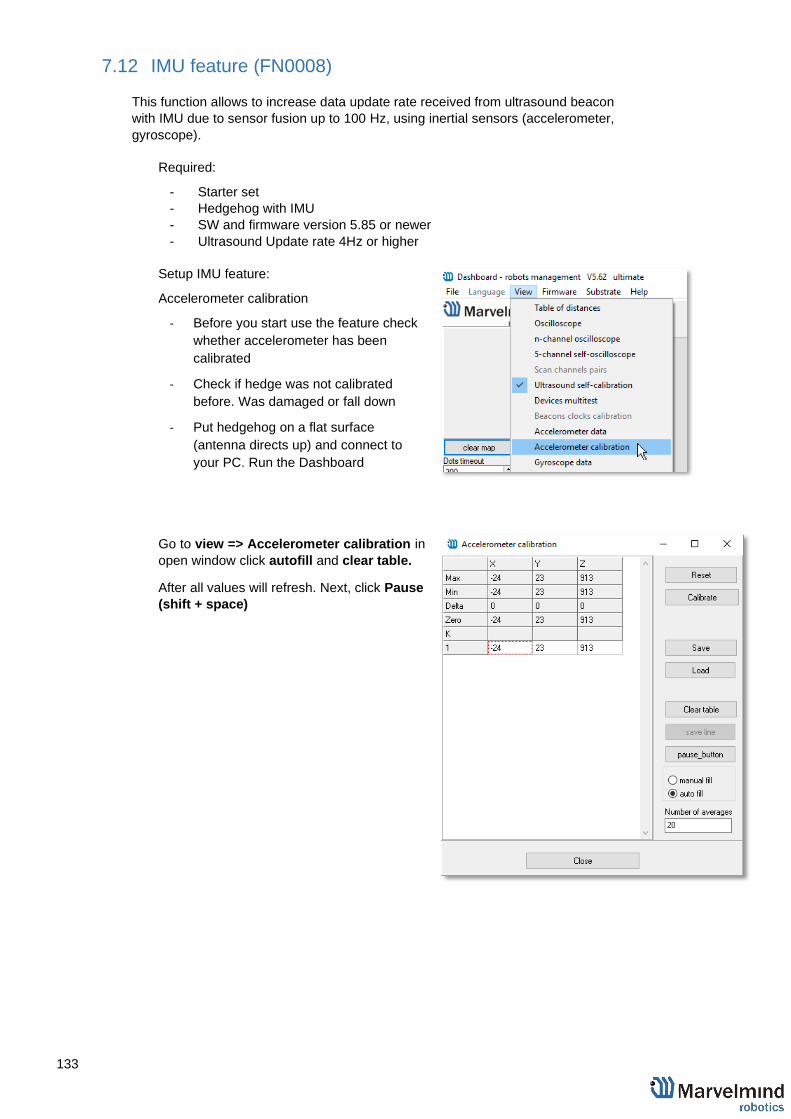
133
7.12 IMU feature (FN0008)
This function allows to increase data update rate received from ultrasound beacon
with IMU due to sensor fusion up to 100 Hz, using inertial sensors (accelerometer,
gyroscope).
Required:
- Starter set
- Hedgehog with IMU
- SW and firmware version 5.85 or newer
- Ultrasound Update rate 4Hz or higher
Setup IMU feature:
Accelerometer calibration
‐ Before you start use the feature check
whether accelerometer has been
calibrated
‐ Check if hedge was not calibrated
before. Was damaged or fall down
‐ Put hedgehog on a flat surface
(antenna directs up) and connect to
your PC. Run the Dashboard
Go to view => Accelerometer calibration in
open window click autofill and clear table.
After all values will refresh. Next, click Pause
(shift + space)
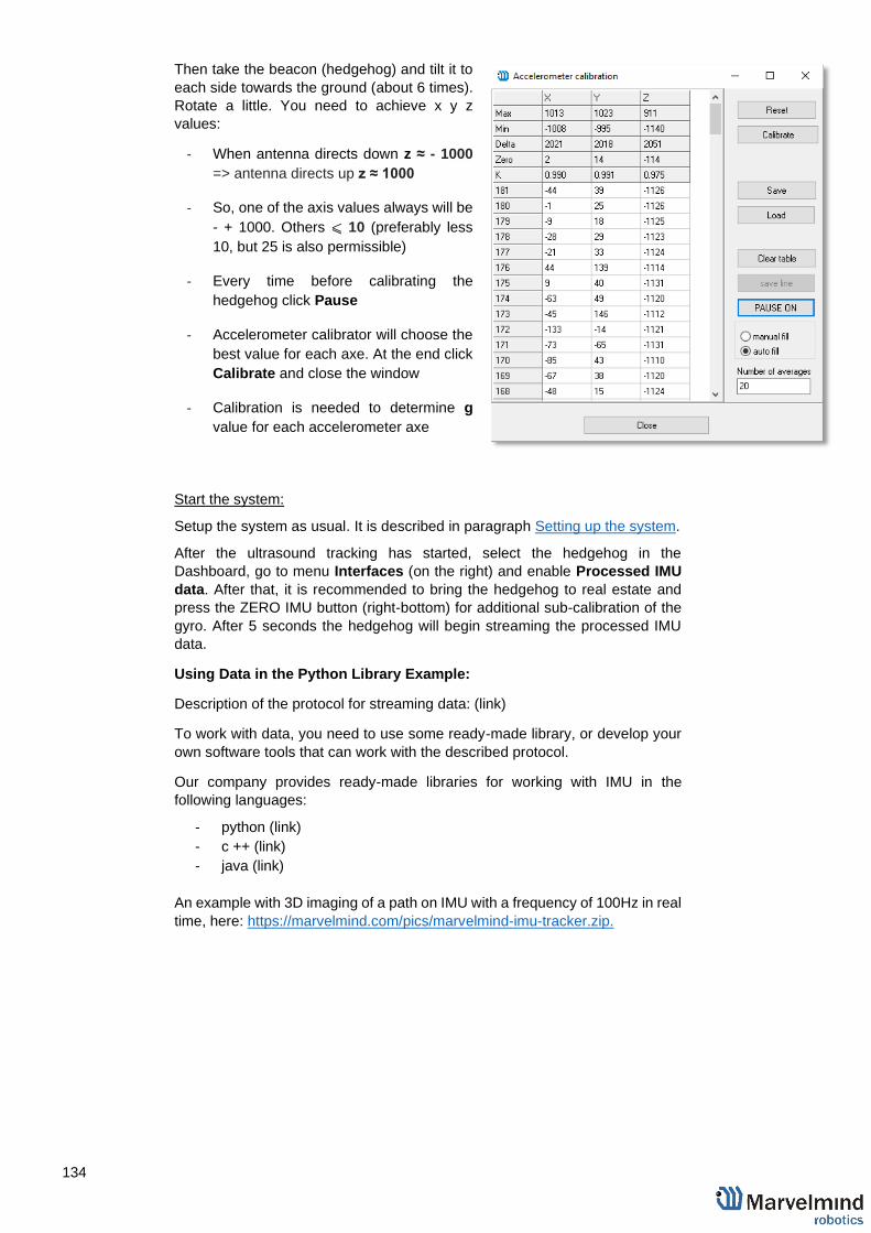
134
Then take the beacon (hedgehog) and tilt it to
each side towards the ground (about 6 times).
Rotate a little. You need to achieve x y z
values:
‐ When antenna directs down z ≈ - 1000
=> antenna directs up z ≈ 1000
‐ So, one of the axis values always will be
- + 1000. Others ⩽ 10 (preferably less
10, but 25 is also permissible)
‐ Every time before calibrating the
hedgehog click Pause
‐ Accelerometer calibrator will choose the
best value for each axe. At the end click
Calibrate and close the window
‐ Calibration is needed to determine g
value for each accelerometer axe
Start the system:
Setup the system as usual. It is described in paragraph Setting up the system.
After the ultrasound tracking has started, select the hedgehog in the
Dashboard, go to menu Interfaces (on the right) and enable Processed IMU
data. After that, it is recommended to bring the hedgehog to real estate and
press the ZERO IMU button (right-bottom) for additional sub-calibration of the
gyro. After 5 seconds the hedgehog will begin streaming the processed IMU
data.
Using Data in the Python Library Example:
Description of the protocol for streaming data: (link)
To work with data, you need to use some ready-made library, or develop your
own software tools that can work with the described protocol.
Our company provides ready-made libraries for working with IMU in the
following languages:
- python (link)
- c ++ (link)
- java (link)
An example with 3D imaging of a path on IMU with a frequency of 100Hz in real
time, here: https://marvelmind.com/pics/marvelmind-imu-tracker.zip.

135
7.13 IMU axis positioning
HW v4.9 IMU axis positions
Mini-TX IMU axis positions
Mini-RX beacon IMU axis positions

136
7.14 Player feature (FN0009)
This function is used to view the distance passed, the flight of the copter, etc. The
player displays statistics on the maximum and average speed, the path traveled
1. Go to File=>player
2. This is how the starting player menu looks like
Select log – opens save log file
Play – launch the player
RAW – if clicked, player shows raw data
Smooth – if clicked, player shows smooth data

137
3. Now log is loaded. Important: for recording log file click Save map for saving
all the beacons locations and attaching all the beacons to the log
At the top of the player you can see 5 outputs:
Limited area distance between black triangles under slider. You can move
triangles and zoom, place cursor on the slider + mouse wheel. Triangles limit the
area in which player works and the statistics is calculated
Starting Log
Start of Playback
Currently Playing
End of Log
End of Playback

138
4. In play mode: grey points – RAW data, blue –
Smooth
Choose the hedgehog will be displayed
In the main Dashboard window, you can turn off
displaying service areas and stationary beacons
by clicking Service areas visible, Stationary
beacons visible.
Statistics displayed depends on the chosen
hedgehog in the list
Max smooth forward, smooth backward –
depth smoothing
Smooth threshold - smoothing ratio.

139
7.15 Real-time player feature (FN0010)
Real-time player is a feature, which makes the tracking path smoother. As far as it looks
backward and forward it certain latency based on the selected parameters.
‒ Real-time player turned on by default
‒ You can turn it off if you need less delay
‒ You can tune it whether you need:
‒ Backward – amount of dots which player ‘looks’ backward to provide
smooth tracking
‒ Forward – amount of dots which player ‘looks’ forward to provide
smooth tracking
Tracking example:
Real-time player turned off

140
Real-time player turned on

141
7.16 CSV format
Current Dashboard version supports additional timestamp. See the attached
screenshot, the UNIX time in milliseconds is the first value.
In each line comma separated values, CSV:
- UNIX time in milliseconds (time since 1970.01.01) - time from previous record in milliseconds - time from running dashboard in milliseconds - address of hedgehog - X coordinate of hedgehog, meters - Y coordinate of hedgehog, meters - Z coordinate of hedgehog, meters - address of stationary beacon - raw distance from hedgehog to stationary beacon, meters
The last pair (beacon address, distance) is repeated n times equal stationary
beacons quantity in the system.

142
8. Interfaces
Indoor “GPS” system supports many external interfaces that can feed measured
location data to an external system (robot, copter, VR, etc.).
There are two different ways to obtain the mobile beacons’ location data from the
system:
1. From the mobile beacons
- Each mobile beacon knows its own position and does not know
the positions of the other mobile beacons
2. From modem/router
- Knows position of every mobile beacon in the system
Data from the mobile beacons and from the modem can be obtained at the same
time, if necessary
A list of the supported interfaces is shown below.
More information on the interfaces can be found here:
http://marvelmind.com/#Interfaces.

143
8.1 Beacon HW v4.9 external interface 4x4 pinout top view
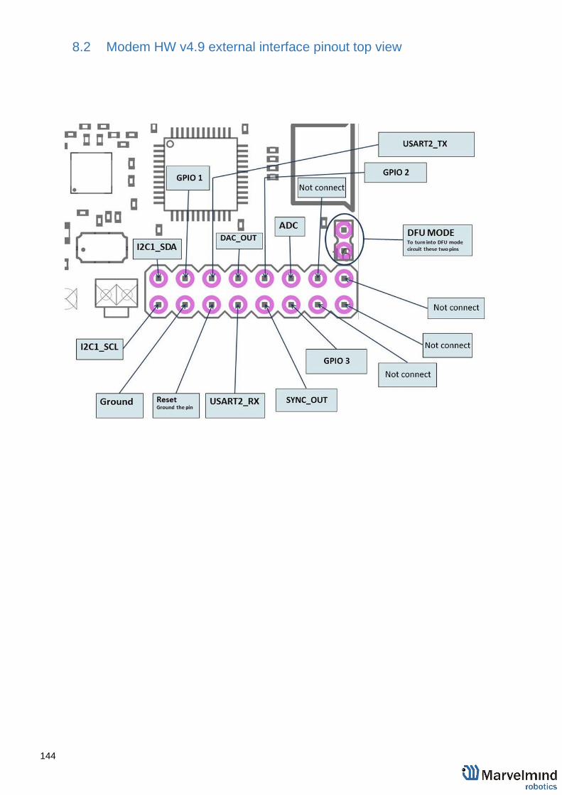
144
8.2 Modem HW v4.9 external interface pinout top view

145
8.3 Super-beacon external interface pinout top view
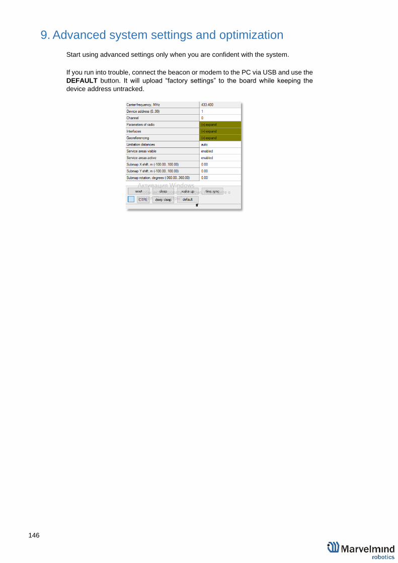
146
9. Advanced system settings and optimization
Start using advanced settings only when you are confident with the system.
If you run into trouble, connect the beacon or modem to the PC via USB and use the
DEFAULT button. It will upload “factory settings” to the board while keeping the
device address untracked.

147
9.1 Time Division Multiple Access (TDMA)
The steps below describe how to run IA with TDMA feature, which helps to improve the tracking quality in complex situations.
Suitable for IA only. Use IA Software
Beacons HW v4.9 should have different frequencies
When you work with two TDMA submaps, update rate reduces twice.
10.1.1. Mount stationary beacons in according to the TDMA chapters in
Placement manual.
10.1.2. Wake up beacons included in Submap0. Enter the values in the table
“distance between beacons”, Freeze it. If necessary, set the shift,
rotation, height, etc. Draw a service zone (More info: Submaps feature
description).
10.1.3. Wake up beacons included in Submap1. If the submap uses beacons
from other submaps, you must add them to the current one. Draw a
service zone, fully crossing with Submap0’s service zone.
10.1.4. If submaps with the same set of frequencies intersect, it is necessary to
use TDMA. (This is the mode of sequential radiation, when for each
stationary beacon the number of the cycle in which it should emit and
the number of cycles of radiation after which these numbers are
repeated is set)
For example, in the room there are beacons 19KHz, 45KHz and two
31KHz and submaps respectively 19KHz+31KHz and 31KHz+45KHz
both include beacon 31KHz, therefore for all beacons the length of the
TDMA sequence is set to 2, while the position in the TDMA sequence
for beacons in 19KHz+31KHz submap is set to 0, and for beacons in
31KHz+45KHz submap is set to 1. As a result, the radiation of beacons
in submaps occurs sequentially, first 19KHz+31KHz submap, then
31KHz+45KHz submap. You can also use absolutely the same set of
frequencies in submaps (Submap0 = 19KHz+31KHz, Submap1 =

148
19KHz+31KHz)
10.1.5. Activate mobile beacons.
10.1.6. Freeze the entire map. Now, you can work with it.
10.1.7. If you have any jumps, that can mean that you have wrong submaps’
positions. Unfreeze all and try to move it until you get their correct
positions.
TDMA modes:
System supports two modes of TDMA:
‒ Mode 1 (Adaptive): Hedge determines which submap sees it better at
the moment, and tracks in it. It can give better tracking, but in bad
conditions, it may cause mistracking
‒ Mode 2 (Classic): Hedge tracks in two submaps one by one. It can give
solid 50/50 tracking in conditions where one submap can’t see the
hedge at all. After measurements, Real-Time Player makes tracking
smooth, filtering out mistracking
Each mode has its pros and cons. Try them both and choose the best suiting
for your case.
How to change modes:
‒ Choose hedge
‒ Go to Ultrasound -> TDMA mode
‒ Left mouse button click to change

149
9.2 Increasing update rate
The update frequency is affected by 2 main parameters:
1) Radio profiles
2) Room dimensions (tracking areas)
If you need to tune the update rate of tracking, do the following:
1) Radio profiles:
There are 3 radio profiles available: 38kbps, 153kbps, 500kbps:
‒ 38kbps is the slowest, but is able to cover a greater distance
‒ 153kbps - average speed, overcomes the average distance (default)
‒ 500kbps is the fastest, but works at a shorter distance
Accordingly, to raise the update rate, we recommend switching to 500kbps.
How to:
In the settings bar of each device in the system (including modem),
change the Radio profile parameter to 500kbps (or any you need). It is
situated in the Dashboard, on the right side of the Dashboard screen.
Tip: Change the beacons’ profile before modem’s, in order not to lose
your beacons. It allows you to do it remotely
2) Room dimensions (tracking areas)
Update rate is also having linear dependence with tracking distance (distance
between stationary and mobile beacon):
Longer distance – lower update rate
Smaller distance – higher update rate
If you have room 10x10m, change maximum distance setting. This will limit
the system to the maximum measurement distance.
How to:
‒ Go to the submap settings (click on the submap icon)
‒ Change maximum distance value in meters (20 is a default)
Tip: Do not enter very small value, use 1-2 meter’s margin. Also, do not
use 20 meters if you have small tracking area. Tune carefully
.

150
9.3 Reducing delay
Exact delay / latency depends on many factors:
‒ IA or NIA
‒ From modem or from the beacon
‒ IMU sensor fusion or regular ultrasonic only
‒ Radio profile
‒ Realized update rate
‒ Any sort averaging or Real-time player enabled or not
The range is from (1) ~12ms for data from a mobile beacon via USB with IMU
fusion enabled and not averaging at all to (b) ~150ms with 30m-submap and
update rate in ultrasonic of 7Hz and not averaging to (c) 2 seconds with the same
settings as in (b), but Real-Time Player with settings 16, i.e. it takes into account
up to 16 previous readings before giving out the new one.
The delay is configured by two main settings:
1) Real Time Player
2) Window of averaging setting (For NIA) and Prefiltration coefficient (For IA)
If you need to tune the delay of tracking, do the following:
1) Turn off the Real-Time Player (works for IA and NIA)
2.1) Change the Window of averaging setting value to 0 (For NIA):
‒ Choose Modem -> Window of averaging (in the right tab) -> Enter
0 value
2.2) Change the Prefiltration coefficient setting value to 0 (For IA):
‒ Choose your mobile Mini-RX beacon. Go to Ultrasound ->
Prefiltration coefficient -> Enter 0 value

151
9.4 How to Place Beacons
Avoid placing beacons on long sound-conducting objects
This is very rare but may happen under some special circumstances.
The best practice is to place beacons (stationary and mobile) in places that would
not result in the transfer of ultrasound energy from the beacon’s board/case directly
to the place it is attached via a medium other than air. For example, solid attachment
of a beacon to a long horizontal metal tube may result in the following:
- Sound emitted from the beacon propagates directly to the metal tube.
- Propagation losses inside metal are much smaller than in the air
Moreover, the tube may act as a low-loss waveguide.
- If the tube is solid enough and long enough, there may be an unusual
effect where the receiving beacon receives the signal sooner than
expected, i.e., sooner than the distance divided by the speed of sound in
air. That happens because the speed of sound in metal is much higher
than the speed of sound in the air. The ultrasound signal may even look
stronger than the real signal propagated through the air due to the lower
amount of losses of ultrasonic in metal than in the air.
- It is good practice to place beacons on something relatively soft or
something that does not conduct sound.
Place beacons in a way that provides the proper ultrasonic coverage. It must
be one beacon in the line of sight of minimum 2 beacons. Try to locate them
under ceilings to avoid shadows, walls etc.
- Optimal settings for stationary beacons in small and big rooms.
- Use 30–50 ultrasonic pulses for larger places and the default 5 pulses for
smaller places.
- Optimal settings for noisy environment.
There are several ways to reduce impact:
- Mobile beacons can be placed very close to the source of noise without
harm, but stationary beacons should be placed further from the noise
because they are receiving the ultrasound, whereas the mobile beacon is
emitting the ultrasound.

152
9.5 Using the Oscilloscope
- Monitor the ultrasonic signal from one beacon to another
- Use Dashboard => View => Oscilloscope to monitor ultrasonic signals from
one beacon to another
- It is a very powerful tool, because it also gives information on the background
noise, level of the signal, echo, etc. With this tool, it is easy to set up the proper
ultrasonic threshold on the Dashboard.
Echo
External noises look
similarly. Thus,
choose the
ultrasonic threshold
below this value, for
example, -500 to -
2000
Type the reference beacon
number. and press
Enter
Choose the beacon to
test
Ultrasonic signal
front
Trigger (red line)
Emittion counter

153
9.6 Proper Ultrasonic Signal Detection
When external noise is high, identify the source. Usual sources include:
- Ultrasonic-based volume or movement detection alarm systems
- Other robots using ultrasonic
- Parktronics
- Sources of very strong white or impulse noise (air guns, air press,
cutters, vacuum cleaner, etc.)
- Rotors of drones/copters
- Marvelmind Indoor Navigation System uses proprietary 31kHz frequency for
ultrasonic signal and employs additional filtering to combat external noise.
This also makes the system rather immune against the “usual suspects.”
However, if the external noise is too strong, its source is too close, or it’s
emitting a strong signal on frequencies close to 31kHz or white noise, the
system functionality can be affected.
- The best things to do in this case are to (1) identify the beacons that are
affected. Usually, they are those that are the closest to the source of noise;
(2) manually reduce the gain of the affected stationary beacons so that the
signal from the mobile beacon would have a 1000–1800 amplitude. That
would give the best signal-to-noise ratio. Don’t make the gain too high. The
noise will be amplified, but the desired signal will be saturated and signal-to-
noise ratio will be poor.
- The gain settings may be very non-linear. There is almost no change at 4000
to 3000. But around 2500, the gain starts reducing very quickly (1200 – for
some HW versions). By setting the gain manually, it is possible to find the
optimal gain to obtain the highest signal to noise ratio so the system can work
even in very challenging external conditions.
- When the map is formed, only the mobile beacon is emitting, whereas
stationary beacons are not. Thus, it does not matter how close the mobile
beacon is to the source of the noise. However, it matters how close the
stationary beacons are to those sources. Select the positions of the stationary
beacons accordingly - place them further away from the noise sources.

154
9.7 Using hedgehog.log file
- The system automatically records all measured positions in the hedgehog.log
file that is stored in the same folder as the Dashboard.exe file
- The data is written in csv format; each line describes the position of one of the
hedgehogs at a certain moment
- The line format is described here.

155
9.8 System Accuracy Evaluation
Accuracy of distance measurement.
- Marvelmind navigation system can measure distances between beacons with accuracy of +/- 2cm if correct ultrasound speed is used.
- The ultrasound speed depends on several factors: temperature, pressure, and humidity. Other factors have an insignificant effect.
- The main factor is temperature. In temperature range of -20…+50 °C the
speed of ultrasound changes on about 0.6 m/ (s* °C). It gives distance
error about (0.6 / 340) *100% ~ 0.17%/ °C. So caused by incorrect
temperature setting absolute error of distance measurement is 0.17% of
real distance between beacons. For example, with distance 30 meters and
5 °C error, this gives 0.85%*30 ~ 0.25 meters’ error. Marvelmind system
allows to setup temperature of air in the system settings.
Accuracy of position measurement.
- Marvelmind system uses trilateration algorithm to calculate position by distances. The inaccuracy of position calculation is related to inaccuracy of distances measurement and to geometry of relative location of stationary and mobile beacons
- Basic trilateration formulas are given in this article:
https://en.wikipedia.org/wiki/Trilateration
- As you see, the position of mobile beacons X, Y, Z is calculated from positions of 3 stationary beacons which are set by values of d, i, j. One of the beacons was shifted to (0,0) position to simplify formulas in the article. In formulas for X, Y we see d and j in denominators. This means that with low values of d and j small error of this value can cause significant position error
- Please see the picture of the beacons in the article - in more simple words, in means that if one of three beacons is close to line connecting other two beacons, it gives increased inaccuracy of locating mobile beacon
- For example:
- assume d= 10, i= 5, j= 0.1, r1= 7, r2= 7, r3= 4.8 - We get x= 5, y= 2.4375, z = 4.25 - If we suppose that j=0.101 (0.1 cm error), we receive x= 5, y= -0.06,
z= 4.89 - You see very large Y error
- Another example for Z. Assume mobile beacon is relative close to plane of stationary beacons:
- d= 8, i= 4, j= 6, r1= 5.02, r2= 5.02, r3= 3.01 - This gives X=4, Y= 3.01169, Z= 0.36 - If we suppose r3= 3.0 (1 cm error), we receive X=4, Y= 3.016, Z=
0.44. Error on Z is about 8 cm
- Also, with r1= 5, r2= 5, r3= 3, Z will be 0. As you see, low change of
distances causes large change of Z value near the plane.

156
9.9 Calibration of the accelerometer
To calibrate an accelerometer on your beacon with IMU, you can do the following steps:
- Connect the mobile beacon via USB to the Dashboard
- Make sure that the beacon has IMU on board: open View / Accelerometer menu
and view / gyro data. In the presence of IMU graphics in these windows should
display the angular velocity and acceleration when moving the mobile beacon
(turn it in hands).
Close the window of the accelerometer and gyro data
- Open the calibration window: View / calibrate the accelerometer
- When calibrating, it measures the data of the free fall (gravity of the Earth)
corresponding to each of the three axes X, Y, Z. The initial ones from these
calculations remember the correction shifts indicated in the table as "Zero" and the
correction factors indicated as "K"
- The switch at the right bottom of the window should be in the AutoFill position
- Before starting the calibration, click the Reset button at the top of the window -
zeroing the current calibration results
- To calibrate: slowly, without jerking, manually turn the beacon in each of the 6
positions and keep it still for 1-2 seconds:
- The starting position - the beacon lies on the table; the antenna is pointing
upwards (calibration Z +)
- The beacon is turned upside down, the antenna pointing down (calibration
Z-)
- The beacon is on the end, the sensor RX1 is pointing towards the table
(calibration Y +)
- The beacon rests on the end, the RX3 sensor points toward the table
(calibration Y-)
- The beacon rests on the end, the RX2 sensor is directed towards the table
(calibration X +). In order not to interfere with the USB connector, the
beacon can be placed on the edge of the table, so that the cable hangs
down
- The beacon rests on the end, the RX5 sensor points toward the table
(calibration X-)
- In each measurement, the readings of the accelerometer are corrected by Zero
and K.
At the end of the measurement of 6 points 7.1 ... 7.6, in the serviceable
accelerometer Zero should be close to zero, and K close to 1, see the screenshot.
If not - check if you forgot any of the points 7.1 ... 7.6.
- To save the results, click Calibrate.

157

158
9.10 Settings to obtain correct north direction
- In some cases, it is necessary to obtain a correct north orientation of the map
for NMEA output from Marvelmind system. For example, when using a
Marvelmind mobile beacon as the navigation data source for Pixhawk installed
on a copter, correct north is required for correct yaw control of the copter. The
Marvelmind system cannot determine north automatically, so the user should
make corrections after building and freezing the map. It can be done in one of
two ways:
1. Rotate the Marvelmind map using the dashboard, as shown on the
attached screenshot
2. You can also view the video:
https://www.youtube.com/watch?v=AsYXrtg7aVU&feature=youtu.be
- Enter the angle correction (the angle shown on screenshot) on the Pixhawk side
from the Mission Planner of APM Planner
- Refer to the parameter "BCN_ORIENT_YAW":
http://ardupilot.org/copter/docs/parameters.html?highlight=bcn_orient_yaw
- Beacons may issue raw sensor data. To learn how to obtain this data, please
check this protocol:
https://marvelmind.com/pics/marvelmind_beacon_interfaces.pdf
- You can receive the data byte-by-byte and check for the required packet header
- See an example here:
http://www.marvelmind.com/downloads/2017_02_08_C_example.zip.

159
9.11 Communication of Pixhawk with Marvelmind mobile beacon
The Marvelmind mobile beacon can be connected to Pixhawk (and to any other
hardware or software that inputs GPS according to the NMEA0183 protocol).
The mobile beacon can send GPS data via UART and USB (virtual UART)
interfaces. For further explanation, please check out this document.

160
9.12 Sending path to robot
1. The dashboard sends request to modem via USB.
Procedure of sending these requests in dashboard is shown on second screenshot.
This format of request is described in section 8 of modem protocol:
hhttps://marvelmind.com/pics/modem_usb_protocol.pdf
Modem transmits data to the hedgehog via radio, using our proprietary protocol

161
2. the hedgehog communicates with robot via UART. Hedgehog sends data according to
section 2.3.1 of this protocol:
https://marvelmind.com/pics/marvelmind_beacon_interfaces.pdf
The robot should confirm receiving data by response packet shown in section 2.3
This communication on the robot side is implemented in the Arduino example on our
site. As you can see in the protocol, robot should not request the waypoints, the
hedgehog will send the waypoints when they will be transmitted from dashboard.
But robot should confirm receiving each waypoint by this packet:
[0x03,0x47,0x01,0x02,0x00, <2 bytes of checksum>]
How to send a path:
‒ Choose mobile beacon in the dashboard

162
‒ Right mouse button on it -> Set movement path
‒ Shift+Left mouse click to add point

163
‒ Shift+Left mouse click on point, to remove that point
‒ Click on Upload path to send it to robot
‒ Path loaded
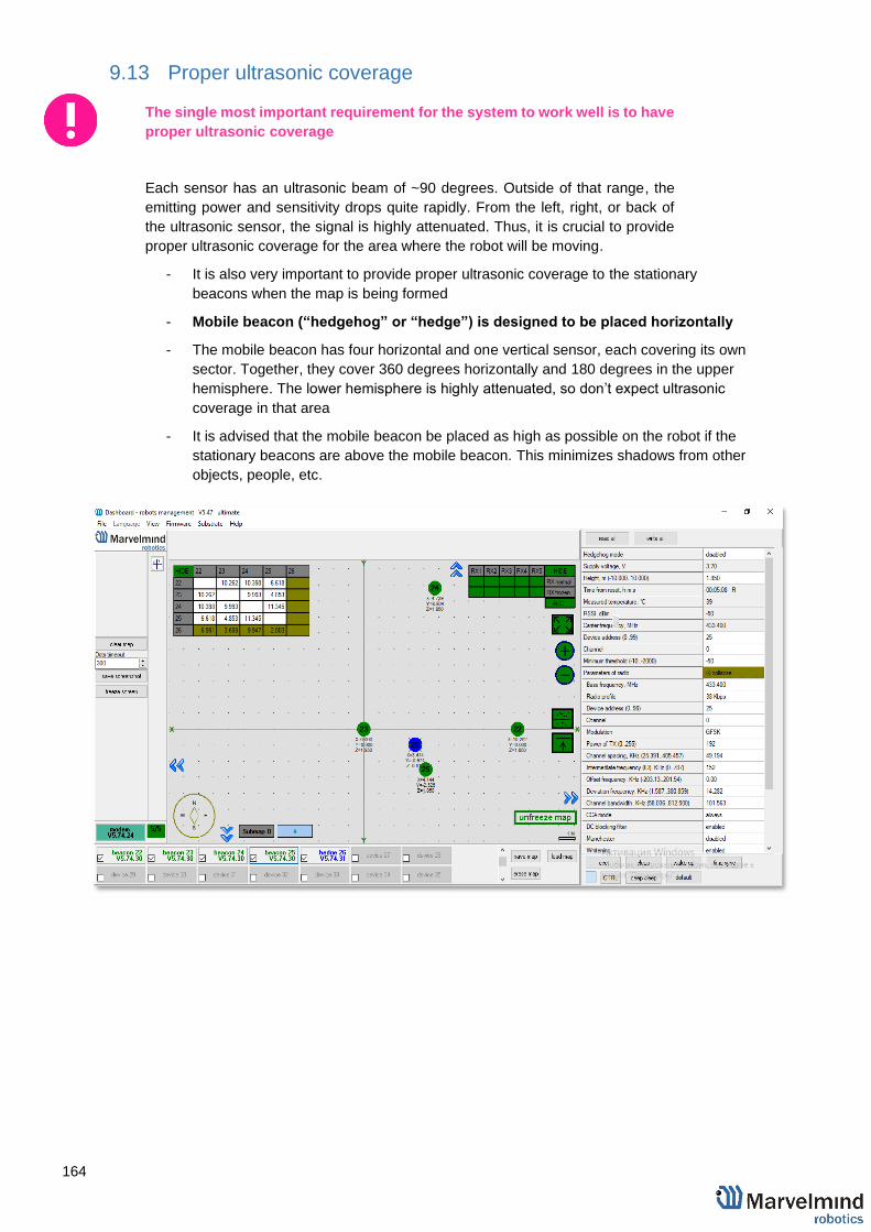
164
9.13 Proper ultrasonic coverage
The single most important requirement for the system to work well is to have
proper ultrasonic coverage
Each sensor has an ultrasonic beam of ~90 degrees. Outside of that range, the
emitting power and sensitivity drops quite rapidly. From the left, right, or back of
the ultrasonic sensor, the signal is highly attenuated. Thus, it is crucial to provide
proper ultrasonic coverage for the area where the robot will be moving.
- It is also very important to provide proper ultrasonic coverage to the stationary
beacons when the map is being formed
- Mobile beacon (“hedgehog” or “hedge”) is designed to be placed horizontally
- The mobile beacon has four horizontal and one vertical sensor, each covering its own
sector. Together, they cover 360 degrees horizontally and 180 degrees in the upper
hemisphere. The lower hemisphere is highly attenuated, so don’t expect ultrasonic
coverage in that area
- It is advised that the mobile beacon be placed as high as possible on the robot if the
stationary beacons are above the mobile beacon. This minimizes shadows from other
objects, people, etc.

165
- Example of proper positioning of the mobile beacon can be found here:
https://youtu.be/PFgNPkLGCDk
- The beacon is placed horizontally and above other objects that can cast a shadow on
the stationary beacons
- Keep the radio signal’s strength under control
- The RSSI (Dashboard => right menu) of any beacon/modem must not be higher than
-25dBm. Otherwise, the system may malfunction
It is recommended the distance between the modem and beacons
be no less than 0.5–1m. Beacons can be placed as close to each
other as needed. If a beacon is extremely close to the modem,
disconnect the antenna from the beacon. Monitor the Received
Signal Strength Indicator (RSSI). It must be in the range of -25 to -
70dBm. An RSSI of less than -70dBm will work too, but packet
losses may start occurring. The quality of the radio connection very
much depends on external interference as well because the used
band is ISM (either 915MHz or 433MHz) and there are numerous
co-existing systems.
Use 30 - 50 periods (pulses) in settings instead of the default 5.
Select:
Ultrasound settings => Number of periods
When you have large errors in position estimation (more than a 1m
inaccuracy), use the embedded Oscilloscope on Dashboard =>
View to determine which stationary beacon is jammed
Reduce the gain of the ultrasonic manually depending on your
system

166
9.14 Sensors settings: example for 2D and mobile beacon
Beacon 2
RX1 and RX4 emit ultrasound in normal mode for better ultrasonic signal exchange with Beacon 3. In frozen mode RX2 added as working sensor. The rest sensors are turned off
Changing sensors’ settings could be found in
the panel in the upper right corner of the
Dashboard during your beacon is connected to
the computer
Beacon 3
RX3 and RX4 emit ultrasound in normal mode
for better ultrasonic signal exchange with
Beacon 2. In frozen mode RX2 added as
working sensor. The rest sensors are turned off
Beacon
Beacon
2D
Hedgehog
7

167
9.15 Powering beacons
Depending on the type of beacon, may be internal battery, or external USB power supply, for
more details check comparison table
Battery lifetime totally depends on the mode of operation and can be varied between several days
to several months (or more for special applications)

168
10. Frequently Asked Questions
Please check this forum for more information. Here we will answer the most
common questions
1 What is the proper way to place the beacons?
- The actual distance between beacons must be ≤ 30 m. Provide the line
of sight from one beacon to minimum two others
2 How far can beacons be located from modem?
- In the open space the distance from the modem to the beacon can reach
several hundred meters
3 What if hedgehog shown as orange circle or inside
in the Dashboard?
- Blue - normal mode and confident tracking
- Orange - system provides the best location data possible, but
confidence is lower, than blue
- - lost radio packets or no ultrasound coverage
4 What is the obstacle for ultrasound?
- The real obstacles for ultrasound are walls (concrete), glass, metal. If
you need to cover a multiple-floor territory you can use our Submap
feature in which case the tracking will not be interrupted
5 How the system works in very low and very high temperatures?
- System is designed for normal office-like conditions and temperatures 0
ºС - 40 ºС
- You can see some other types of beacon (outdoor, explosion safe, etc.)
in the comparison table
- We also possible to produce some special versions, which will suit your
case. Please write to [email protected]
6 Are beacons resistant to explosions, dust, dirt, water, noise?
- - Low-frequency noise (motor noise, industrial equipment) does not
interfere with the normal operation of the system
- You can see some other types of beacon (outdoor, explosion safe, etc.)
in the comparison table
7 What is the time of delay between positioning the object and
respond?
- The delay is directly proportional to the update rate. For example, if
update rate is 16 Hz delay is 1.2:1.5x60ms
- The limit is 1.5x times the maximum distance between the stationary
beacons. To expand the service area, please follow the instructions
shown in the attached screenshot. Notice that positioning the mobile
169
beacon far from stationary beacons and close to their plane may result
in increased positioning error because of bad geometry of measurement
8 How to define IMU or not IMU beacon?
- Check white sticker on the box and on the beacon's bottom /IMU - with
IMU
- Connect beacon via USB: Dashboard => View => Accelerometer data
9 Can we use none-IMU beacon as mobile beacon or not?
- Yes, you can (https://www.youtube.com/watch?v=A4aRsjH2-_E)
10 What is the reason to choose 915Mhz vs 433Mhz?
- The 915MHz version is designed for the US, Canada and Americas in
general. The ISM band (license-free band for industrial, science and
medical applications) in those countries is 915MHz
- In Europe, it is 433MHz
11 Device do not connect via USB?
- Use USB cable with long metal part. If you have any problems with USB
connection, change the cable first. One cable can work for one device
and do not work for other
12 Does the orientation of the beacon matter?
- Yes, it is. Place and orientate it in positions, where sensors can “hear”
each other. v4.9 beacon has ≈90° per sensor coverage(illustration),
Mini-RX and Industrial-RX have ≈180° coverage(illustration)
13 Why Dashboard do not see more than 4 beacons
- System has a limitation of 4 beacons per submap. If you have more than
4 beacons, just create another submap, and beacons will appear

170
11. Troubleshooting check-list
If you have any problems with the system, follow this simple steps:
- Update SW on modem and beacons
- Now, connect all beacons and modem one by one and press Default button in the
Dashboard (When updating the SW, please, press Default button to make sure that
beacons really have default settings. Otherwise, modem may be calling on a wrong
channel or something)
- Press Erase map

171
Check-list before starting the system:
IA and NIA SW differs
For IA you should use stationary beacons with different frequencies
‒ Make sure that you use correct SW. Inverse Architecture(IA) SW for Inverse system, Non-Inverse Architecture(NIA) SW for Non-Inverse system (Architectures comparison)
‒ Make sure that your beacons are 3.5V and higher before using. If not, charge it for 2-3 hours.
‒ Keep modem 1-2m away from beacons. if closer, the beacons radio may be overloaded
‒ Antenna’s recommendations: ‒ The antenna must be kept as straight as possible. Otherwise it will
reduce the effective range ‒ The antennas must be kept away from conductive materials, such as
metal and carbon by at least a half inch ‒ Keep the antennas away from the motors and other noise sources as
much as possible
‒ Use USB cable with long metal part. If you have any problems with USB connection, change the cable first. One cable can work for one beacon and do not work for other
‒ Be sure that you use SW from the same pack
‒ When updating the SW, please, press Default button to make sure that beacons really have default settings. Otherwise, modem may be calling on a wrong channel or something
‒ Start with simple configuration (10x10m square, 4 stationary beacons)
‒ Do not obstruct line of sight between beacons
‒ Build the map first, freeze it, then wake up the “hedge”
‒ Number of periods. By default – 5; For longer distances, you shall put it 10-50
Mini-RX beacon may be over discharged. In that case do the following:
‒ Turn off the beacon with DIP switches
‒ Charge it for 1 hour
‒ Turn the beacon on, flash the latest SW via DFU Programming and charge it for 1 hour again


