mars.umhb.edumars.umhb.edu/~wgt/phys2422/Labs/Lab_8/63Word.docx · Web viewOn a small scale, the...
12
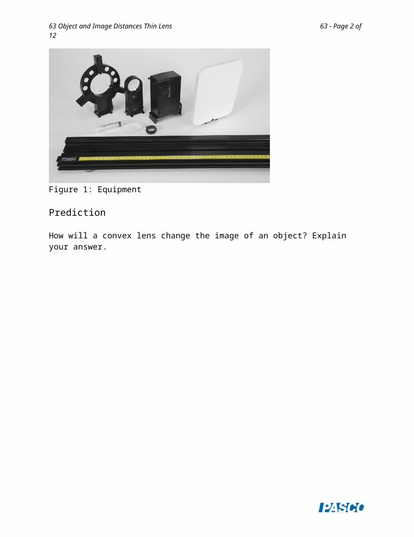
63 Object and Image Distances Thin Lens 63 - Page 1 of 12 Object and Image Distances Thin Lens Equipment 1 Basic Optics Light Source OS- 8470 1 Optics Track OS- 8508 1 Basic Optics Viewing Screen OS- 8460 1 Convex Lens Set OS- 8456 1 Adjustable Lens Holder OS- 8474 1 Adjustable Focal Length Lens OS- 8494 Required but not included: 1 Ruler Water (15 mL) Introduction The purpose of this activity is to determine the relationship between object distance and image distance for a thin convex lens. Use a light source, optics bench, lens, and viewing screen to measure object distance, image distance, and image size.
Transcript of mars.umhb.edumars.umhb.edu/~wgt/phys2422/Labs/Lab_8/63Word.docx · Web viewOn a small scale, the...

63 Object and Image Distances Thin Lens 63 - Page 1 of 8
Object and Image Distances Thin Lens
Equipment
1 Basic Optics Light Source OS-8470 1 Optics Track OS-8508 1 Basic Optics Viewing Screen OS-8460 1 Convex Lens Set OS-8456 1 Adjustable Lens Holder OS-8474 1 Adjustable Focal Length Lens OS-8494
Required but not included:1 Ruler
Water (15 mL)
Introduction
The purpose of this activity is to determine the relationship between object distance and image distance for a thin convex lens. Use a light source, optics bench, lens, and viewing screen to measure object distance, image distance, and image size.
Figure 1: Equipment
Prediction
How will a convex lens change the image of an object? Explain your answer.
63 Object and Image Distances Thin Lens 63 - Page 2 of 8
Background
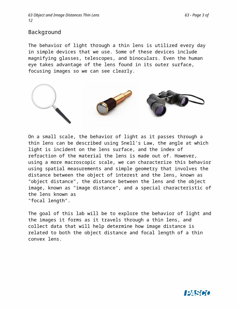
The behavior of light through a thin lens is utilized every day in simple devices that we use. Some of these devices include magnifying glasses, telescopes, and binoculars. Even the human eye takes advantage of the lens found in its outer surface, focusing images so we can see clearly.
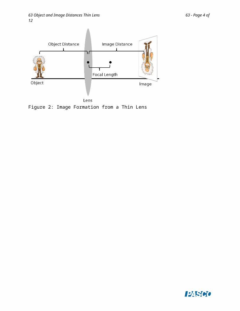
On a small scale, the behavior of light as it passes through a thin lens can be described using Snell's Law, the angle at which light is incident on the lens surface, and the index of refraction of the material the lens is made out of. However, using a more macroscopic scale, we can characterize this behavior using spatial measurements and simple geometry that involves the distance between the object of interest and the lens, known as "object distance", the distance between the lens and the object image, known as "image distance", and a special characteristic of the lens known as "focal length".
The goal of this lab will be to explore the behavior of light and the images it forms as it travels through a thin lens, and collect data that will help determine how image distance is related to both the object distance and focal length of a thin convex lens.
Figure 2: Image Formation from a Thin Lens
63 Object and Image Distances Thin Lens 63 - Page 3 of 8
Setup
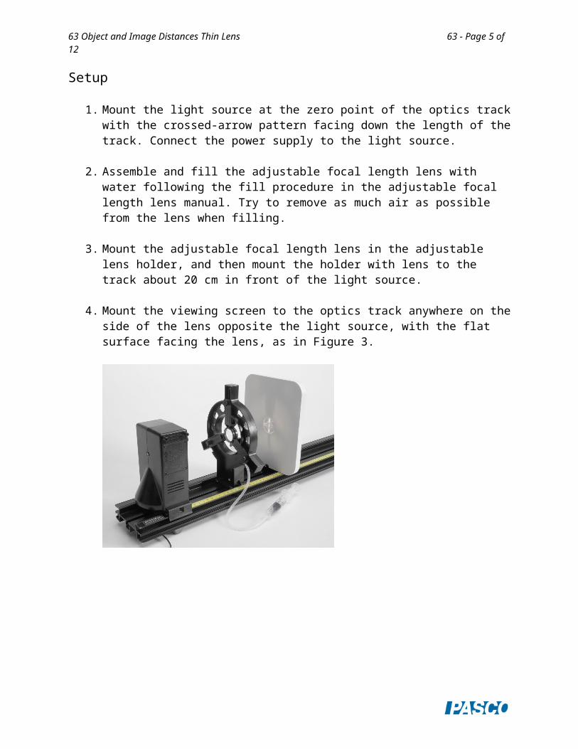
1. Mount the light source at the zero point of the optics track with the crossed-arrow pattern facing down the length of the track. Connect the power supply to the light source.
2. Assemble and fill the adjustable focal length lens with water following the fill procedure in the adjustable focal length lens manual. Try to remove as much air as possible from the lens when filling.
3. Mount the adjustable focal length lens in the adjustable lens holder, and then mount the holder with lens to the track about 20 cm in front of the light source.
4. Mount the viewing screen to the optics track anywhere on the side of the lens opposite the light source, with the flat surface facing the lens, as in Figure 3.
63 Object and Image Distances Thin Lens 63 - Page 4 of 8
Explore
To produce a convex lens, press VERY slightly on the syringe. The harder you press on the syringe, the greater the curvature in the convex lens, but be careful not to press too hard as the lens will pop and water will spill out, or air may get trapped in the lens.
1. With the lens slightly convex, adjust the position of the viewing screen forward or backward until the image of the crossed-arrow pattern is in focus. When the image is in focus, the distance between the lens and the viewing screen is equal to the image distance, and the distance between the crossed-arrow pattern on the light source and the lens is equal to the object distance.
2. A convex lens with greater curvature will have a shorter focal length. How does the image distance change when you increase the curvature of the lens (decrease focal length) while keeping the object distance constant?
3. How does the SIZE of the image change when you decrease the focal length (constant object distance) and does its orientation change?
4. How does the behavior you see compare to your prediction on the first page?
63 Object and Image Distances Thin Lens 63 - Page 5 of 8
5. Setup
1. Make certain the light source is at the zero point on the optics track with the crossed-arrow pattern facing down the length of the track.
2. Mount the viewing screen at the other end of the bench with the flat surface facing the light source.
3. Remove the adjustable lens holder with the adjustable lens and mount the 100-mm glass convex lens to the optics track 500 mm from the light source. Use the metric scale on the optics track and the marks at the base of the light source and lens mount (as in Figure 4) to help set this distance.
Figure 4: Track Markers

63 Object and Image Distances Thin Lens 63 - Page 6 of 8
Procedure
1. In PASCO Capstone, create a table as shown below. Create User-Entered Data sets called “Object Distance”, “Image Distance”, and “Image Height”, all with units of mm.
Table I: Object and Image DistancesObject Distance
(mm)Image Distance
(mm)Image Height
(mm)500475450425400350300250200150125115110
2. The image of the crossed-arrow target should initially appear out of focus. Adjust the position of the viewing screen forward or backward until the image of the crossed-arrow target is in focus.
3. When the image is in focus, measure the distance between the lens and the viewing screen. Record this image distance in Table I.
4. Use the ruler to measure the height of the image. Record the image height in Table I. Use negative values to indicate that the image is inverted.
5. Adjust the position of the 100-mm convex lens to the next object distance listed in Table I of 475 mm.
6. Adjust the position of the viewing screen until the image of the crossed-arrow target is in focus, and then record the image distance and height in Table I.
7. Repeat the same procedure for each object distance value in Table I. Record all values in Table I.

63 Object and Image Distances Thin Lens 63 - Page 7 of 8
Analysis: Distance
1. Create a graph of Image Distance (mm) vs. Object Distance (mm).
2. What value does the image distance approach as the object distance becomes larger (approaches infinity), and what is the significance in this value?
3. What value does the object distance approach as the image distance becomes larger (approaches infinity), and what is the significance in this value?
The graph of image distance versus object distance isn't linear; however, by clicking on either axis label you can select QuickCalcs that will quickly manipulate either axis measurement by operating on it mathematically.
4. Use different QuickCalcs on both axes until the graph shows a linear relationship (you will need to rescale when applying QuickCalcs). What are the x and y variables that show a linear relationship?
5. Apply a linear fit to your data and write the y = mx + b equation that describes the line below (round m to the nearest whole number). Replace y and x using the variables from your answer to the previous question.
6. What is the significance of the y and x-intercepts in your graph/equation?
7. Based on your data and the answers to the previous questions, what is the equation that relates object distance, image distance, and focal length of a thin lens?
Analysis: Magnification
Magnification is a measure of how much an image has been magnified from its original size. Mathematically, magnification is the ratio of image height to object height:
Magnification= Image HeightObject Height
8. In the Capstone calculator, create a calculation for the magnification (it is unitless):
Magnification = [Image Height (mm)]/40
In this calculation, the Object Height has been set to 40 mm. Use the ruler to measure the height of the object, and then enter that value into the magnification.

63 Object and Image Distances Thin Lens 63 - Page 8 of 8
9. Add a column to Table I and select the Magnification calculation in that column:
Table I: Object and Image DistancesObject Distance
(mm)Image Distance
(mm)Image Height
(mm) Magnification
500475
10. Create a graph of Magnification vs. Object Distance (mm) and another graph of Magnification vs. Image Distance (mm).
11. How is magnification related to object distance (proportional, inverse, etc.), and at what object distance is the magnification approximately equal to 1 (object height = image height)?
12. How is magnification related to image distance (proportional, inverse, etc.), and at what image distance is the magnification equal to 1? How does this value compare to the object distance at the same magnification?
13. Based on the responses to the previous two questions, what is the mathematical relationship that relates magnification to object and image distance?
14. What value does magnification approach as object distance approaches the focal length of the lens (100 mm)? What do you think happens to the image when the object distance is less than the focal length of the lens?