MARS: MULTIPLE AUTONOMOUS ROBOTS MARS: MULTIPLE AUTONOMOUS ROBOTS NSF Summer Undergraduate...
18
147 MARS: MULTIPLE AUTONOMOUS ROBOTS NSF Summer Undergraduate Fellowship in Sensor Technologies Kamela Watson (Mechanical Engineering) - Cornell University Advisor: Dr. Vijay Kumar ABSTRACT Robotics is becoming an increasingly important field in engineering research. The MARS (Multiple Autonomous Robots) team at the University of Pennsylvania fabricates small- scale, car-like robots. These robots are fitted with 12 infrared sensors and an omni directional camera for sensing as well as an onboard laptop computer with a wireless network. The robots can perform a variety of functions and tasks that, although seemingly simple individually, can be combined and manipulated to allow the robots to perform more complicated tasks. Over the course of the summer, I have participated heavily in the upgrade of the hardware on the robots. Participating in efforts on calibration, computer casing, and robot chassis, I have helped to make improvements, introduce new ideas, and documenting all of my summer efforts. The following will discuss the overall robot structure and then continue to explain my findings and efforts to the MARS project over the course of the summer. 1. INTRODUCTION Since the early 1980s, many forms of artificial intelligence have become deeply imbedded in our everyday lives. The manufacture of autonomous robots, with the ability to perform tasks that would normally put human life at risk, would be a great societal asset. [3,5] The MARS (Multiple Autonomous Robots) research being conducted at the University of Pennsylvania builds upon and substantially improves existing work. This project has been in existence for about three years. Current technologies allow for supervised robot autonomy, but the MARS objective is to develop capabilities to allow robots to (a) exhibit deliberative and reactive behaviors in autonomous operation, (b) be reprogrammed by a human operator at run-time, and (c) learn and adapt to unstructured terrain. Another goal is to put all of these functions on to an inexpensive robot that is also rather small in size and low on weight. The platform currently being implemented for these robots is Clodbusters. The MARS team has made many progressions towards their objectives. This summer, I had the opportunity to help the team continue with their current work.
-
Upload
nguyennhan -
Category
Documents
-
view
218 -
download
2
Transcript of MARS: MULTIPLE AUTONOMOUS ROBOTS MARS: MULTIPLE AUTONOMOUS ROBOTS NSF Summer Undergraduate...
147
MARS: MULTIPLE AUTONOMOUS ROBOTS
NSF Summer Undergraduate Fellowship in Sensor Technologies Kamela Watson (Mechanical Engineering) - Cornell University
Advisor: Dr. Vijay Kumar
ABSTRACT
Robotics is becoming an increasingly important field in engineering research. The MARS (Multiple Autonomous Robots) team at the University of Pennsylvania fabricates small-scale, car-like robots. These robots are fitted with 12 infrared sensors and an omni directional camera for sensing as well as an onboard laptop computer with a wireless network. The robots can perform a variety of functions and tasks that, although seemingly simple individually, can be combined and manipulated to allow the robots to perform more complicated tasks. Over the course of the summer, I have participated heavily in the upgrade of the hardware on the robots. Participating in efforts on calibration, computer casing, and robot chassis, I have helped to make improvements, introduce new ideas, and documenting all of my summer efforts. The following will discuss the overall robot structure and then continue to explain my findings and efforts to the MARS project over the course of the summer. 1. INTRODUCTION Since the early 1980s, many forms of artificial intelligence have become deeply imbedded in our everyday lives. The manufacture of autonomous robots, with the ability to perform tasks that would normally put human life at risk, would be a great societal asset. [3,5] The MARS (Multiple Autonomous Robots) research being conducted at the University of Pennsylvania builds upon and substantially improves existing work. This project has been in existence for about three years. Current technologies allow for supervised robot autonomy, but the MARS objective is to develop capabilities to allow robots to (a) exhibit deliberative and reactive behaviors in autonomous operation, (b) be reprogrammed by a human operator at run-time, and (c) learn and adapt to unstructured terrain. Another goal is to put all of these functions on to an inexpensive robot that is also rather small in size and low on weight. The platform currently being implemented for these robots is Clodbusters. The MARS team has made many progressions towards their objectives. This summer, I had the opportunity to help the team continue with their current work.
148
2. COORDINATED MOTION CONTROL The abilities of fully autonomous robots to move in prescribed formations can be utilized in many different applications. With formation control capabilities, robots can perform a number of different tasks. For example, the ability to manipulate objects while maintaining formation when moving through a prescribed trajectory can be applied to removing explosives or any other objects from adverse environments. This challenge can be examined in two parts: formation control and cooperative localization/manipulation. All information needed for relative positioning, orientation, and maintaining formation will be received from one or more of the various sensing systems placed on each robot (See Section 3). The robots will first be able to move in a certain formation and then will be able to “trap” an object in order to manipulate it by moving in formation. This has been described as a “trap and flow” method of transporting objects. Three major areas must be investigated to produce a successful “trap and flow” result”: cooperative localization, formation control, and cooperative manipulation. [1,2] 2.1 Cooperative Localization The first major obstacle is how the robots will know where they are relative to each other. Cooperative positioning (the term is from Kurazume et al.) [1] has been studied and built on for our applications. Relative positioning and orientation will be taken from information given by visual imagery rather than just relative positions. One Clodbuster within the formation will be made the reference robot, and the others will be able to determine their relative position from this robot by a cooperative localizer. [1] The cooperative localizer will take images from the omni directional camera on board. Using a catadioptric camera system, vectors to each robot in the formation can be established. A color collar is placed on each robot to identify it, and a color extractor uses these colors to determine distance and direction of each robot. This is accomplished with the use of 3D geometry and linear algebra. This method of localization is easily extended to n robots and is an improvement on decentralization localization methods used before I began work on this project this summer. 2.2 Formation Control Achieving formation control requires the information received from cooperative localization along with added control. Again, one robot is designated the leader of the team, and this robot’s trajectory is determined by a high-level planner. We will also, for now, assume a team of three robots. From the trajectory of the lead robot, the remainder of the team will need to determine their positions and speed. Using linear and angular velocities as inputs, an algorithm is used to determine the team’s route. When the desired separation distances of the second and third robots from the first are determined, then their velocities will be controlled by feedback linearization. In this configuration, it is still possible for the second and third robots to collide, so the distance between these robots must also be set to a desired length.[1]
149
2.3 Cooperative Manipulation Using both cooperative localization and formation control, tests have been run on the robots’ ability to perform cooperative manipulation of an object. Tests ran before this summer by members of the MARS team were for the most part successful. However, these tests used a formation that had been previously determined by a human. How well the robots can perform by choosing their own optimal formation according to object shape is now a subject of interest. [1,2] 3. SENSING Any useful motion or manipulations by a robot require some type of sensing mechanism(s). The Clodbusters’ computer must take from its environment the information it needs and then feed the robots commands to perform their task. The sensing mechanisms on our current robots are omni directional cameras and infrared (IR) sensors. The IR sensors, a recent addition to the sensing technology aboard the robot, have proven very useful for a variety of applications on the robots. Also, replacing the omni directional camera with two or more Web cameras mounted onto the robot is now being considered. The Web cameras are much less expensive than the omni directional cameras and are also less sensitive to damage. They also will need more wires and will take up much more room aboard the robots. An omni directional camera has a great advantage over any other sensing mechanism aboard the robot. These cameras have the ability to see in a full 360º span. Different colors, objects, and distances can all be extracted from the camera, making it a very versatile method of collecting information from the robots’ environment. 3.1 Cooperative Sensing Although a single robot can do many things individually, the number of tasks the robots can complete, and the time needed to complete a task, are greatly improved when all the robots work together as a unit. This is accomplished by giving the robots the ability to communicate with each other and share various information. A wireless network on each computer aboard the robots allows information to be shared using a broadcast protocol. 3.1.1 Inertial Measurement Units Information received from the cameras and IR sensors is very critical in the operation of the robots. But other sensing modalities are needed to gain information not on the robots’ environment, but on their movements. Velocity and acceleration are among these variables. On our robots, velocity is controlled using a Rooster Reversible Speed Controller and sensed using a 2-axis accelerometer. The accelerometer measures acceleration on the plane the robot travels in, and this information can then be integrated to find the actual speed at which the robot is moving.
150
3.2 Dead Reckoning The method of dead reckoning, which can be useful for exploration and localization mapping, would be a valuable tool to integrate onto the Clodbuster platforms. The installation of vehicle odometry could provide position estimation, from which distance traveled, final destination point, and current position can all be measured and the distance left to be traveled can be calculated. Currently there is no odometer on the robots, and this system cannot yet be implemented. 3.3 Range Finders Researchers have used various forms of range finders on their robots, which allow for very accurate reporting of object ranges from the robot. Our team, however, has chosen not to use such devices. The most popular of the ranger finders currently in use is the SICK laser. This device has significant cost as well as weight disadvantages. Since one of the goals of our project is to keep each robot as small and inexpensive as possible, we have opted to not use these types of devices. 3.4 Global Positioning System (GPS) In its current stage, GPS is a potential implementation on the robots. I have done a little research into the benefits and downfalls on applying GPS onto the robots. Currently, there is no need for a system as the robots are being ran mostly indoors with very limited outdoor manipulations. They system is not currently available, but most commercial GPS systems can be easily integrated onto the computer. Although all of the current platforms in use have the ability to operate outside, all of the testing is done indoors and therefore there is no current need for GPS on the robots. 4. USE OF SENSOR TECHNOLOGIES Sensors can be used for countless applications in robotics. We have used the information from our sensors to apply four main functions: obstacle avoidance, wall follower, random wanderer, and blob detection. With these four basic functions, the robots can perform other more complicated tasks. The obstacle avoider ensures that the robot can avoid collisions while in motion while roaming or performing a task. In its current configuration, the obstacle avoider uses the lookup table from the IR sensors to avoid collisions. There are, however, problems with this system. The IR sensors use a very narrow, straight laser to detect objects in their path. If the object is not within the plane that the IRs are set on, the robot cannot “see” the object. In future robots, the camera on board may better be used for the obstacle avoidance task. The omni directional camera has a complete 360º view as well as a much greater range than the IRs. IBots (web cameras) aboard the robot also may prove better than IRs. Their field of vision is limited, at 60º, but their range of approximately 12 meters is over 12 times the range of IR sensors.
151
IRs are also used for the function of the wall follower. Again, look-up tables from the IRs are used to make the robot travel along a wall. These functions works best at slower speeds, as the computer has more time to process the sensor information. At higher speeds, this function may fail, causing a collision. This failure is due to overshoot and the inability of the computer to work fast enough to fix this over-correction. Each robot has also been fitted with a random wanderer function. This function allows the robot to simply wander around its environment, but it will also use its obstacle avoidance function so that it will not collide with any objects. It will either attempt to turn to avoid an object or stop and reverse itself to begin again. The fourth function currently available on our robots is blob detection. The robots can search for a certain color (currently pink) and will advance to that color. This function can be used to make the robot perform other tasks such as a robot/object follower. The robot follower is used in cooperative localization, as described previously. The object follower can be used on any object, moving or stationary. The robot will simply find the color pink attached to it and continue to follow it. This function can be combined with the random wanderer so that the robot will continue to roam until it “sees” the color pink, at which time it will follow the color. 5. DISCUSSION AND CONCLUSIONS My first responsibility of this summer was to improve the design of the last Clodbuster made before my arrival. This design included eight IR sensors taped to the side of the robot, the computer being pinched to keep it stable, and a plastic chassis. Upon leaving this project, my last efforts were towards the third model of aluminum chassis Clodbusters. These robots feature a newly designed “open-air” computer mount, which also includes side mounts for up to twelve IRs. The more open design allows the computer to sufficiently release heat, as there were some problems of the computer over heating. Other problems such as circuit board accessibility, wiring organization, IR calibrations, design flexibility, camera dismount difficulties have all been addressed in the new designs. There are currently still more improvements being made to our designs. A full documentation report has been written to help others who will be working on this project. Included in the documentation are instructions for robot fabrication as well as other useful information for any new researcher to the GRASP lab we work from. 6. RECOMMENDATIONS There are some recommendations for that MARS team at the University of Pennsylvania to continue with their work and look at the previously mentioned improvements as possible implementations to the current robot design. I encourage the team to continue to focus on the objective specifications of the robots, especially small size and weight. There are obvious shortfalls in the performance of our robots with payoffs of size, weight, and cost. These should remain important aspects of the robots’ design.
152
Please see the Appendices for full documentation records including other recommendations. 7. ACKNOWLEDGMENTS I would like to thank some of those people who made my summer experience not only possible, but also an enjoyable learning experience. I would like to first thank my advisor, Dr. Vijay Kumar, who worked very closely with John Spletzer and Camillo Taylor to give us meaningful work to accomplish. I had the wonderful opportunity to work as a team member of the MARS group here at University of Pennsylvania, which included Guilherme Pereira, Aveek Das, Jim Keller, Vito Sabella, and Mike Shall. These people have devoted considerable time and effort to this project, and will continue to work on and improve the Clodbusters. They have worked extensively on all software issues and have been of great help to me when dealing with hardware concerns. Lastly, I would like to thank Sameer Qudsi and fellow SUNFEST student April Harper whom I have worked closely throughout the summer. I would also like to thank the National Science Foundation for their continuing support of the SUNFEST program, which provides undergraduates an opportunity to do meaningful research. 8. REFERENCES 1. J. Spletzer, A.K. Das, R. Fierro, C.J. Taylor, V. Kumar, and J.P. Ostrowski,
Cooperative localization and control for multi-robot manipulation, submitted to IROS 2001.
2. A. K. Das, R. Fierro, V. Kumar, J. P. Ostrowski, J. Spletzer, and C. J. Taylor, A
framework for vision based formation control, Submitted to Multi-Robot Systems: A Special Issue of IEEE Transactions on Robotics and Automation, April 2001.
3. History of Robotics and Robots, www.geocities/com/Eureka/7331/hrorobot.htm. July
2002. 4. Curt Anderson, www.darex.com/indurevo.htm 5. Renato S.M. Sabbatini, PhD., Imitation of Life: A History of the First Robots,
www.epub.org.br/cm/n09/historia/trutrles_i.htm. July 2002
153
9. APPENDICES APPENDIX 1. ASSEMBLING WIRES AND PARTS 1.1 Power Connector Cable Assembly:
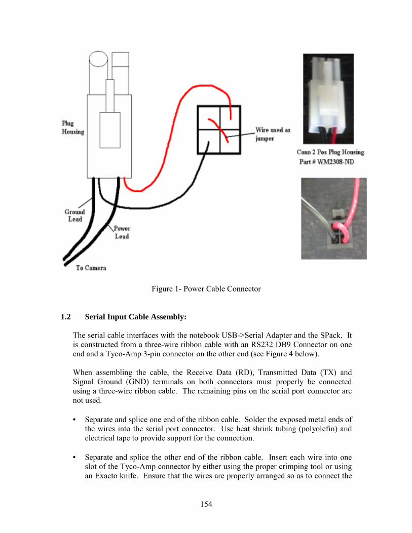
The power connector cable provides power from either an AC adapter or a battery to the SPack board and to the camera on the Clodbuster. The cable must be properly connected to ensure the proper supply of power to each component.
• Splice one end of the power cord wire and splice the ends of two 20 AWG wires
(one red and one black). • Solder together the exposed metal tips of the red wire and the power lead of the
power cord. Also solder together the black wire and the ground lead of the power cord.
• Crimp the soldered ends of the wires into a socket terminal connector (Digikey part # WM2311-ND, Molex mfg. part # 357-28-0201) and insert into the plug housing (Digikey part # WM2308-ND, Molex mfg. part # 351-43-0201)
• Crimp the other ends of the red and black wire into the proper size crimping terminator (Digikey part # WM2311-ND, Molex mfg. part # 43030-0009) and insert into the square connector.
• Use a small piece of wire with crimping terminators on each end as a jumper between the two remaining slots of the square connector.
• Ensure that wires are securely fastened and in the proper order.
WARNING: Improper wiring may damage board.
154
Figure 1- Power Cable Connector
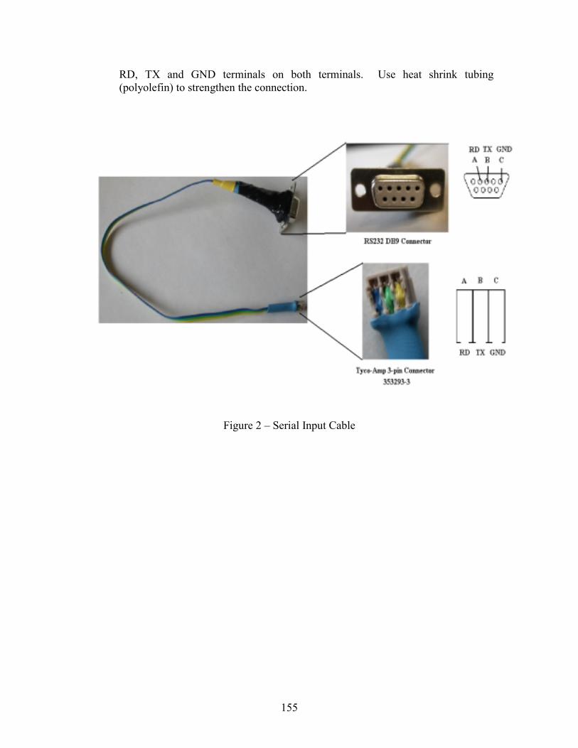
1.2 Serial Input Cable Assembly:
The serial cable interfaces with the notebook USB->Serial Adapter and the SPack. It is constructed from a three-wire ribbon cable with an RS232 DB9 Connector on one end and a Tyco-Amp 3-pin connector on the other end (see Figure 4 below).
When assembling the cable, the Receive Data (RD), Transmitted Data (TX) and Signal Ground (GND) terminals on both connectors must properly be connected using a three-wire ribbon cable. The remaining pins on the serial port connector are not used.
• Separate and splice one end of the ribbon cable. Solder the exposed metal ends of
the wires into the serial port connector. Use heat shrink tubing (polyolefin) and electrical tape to provide support for the connection.
• Separate and splice the other end of the ribbon cable. Insert each wire into one
slot of the Tyco-Amp connector by either using the proper crimping tool or using an Exacto knife. Ensure that the wires are properly arranged so as to connect the
155
RD, TX and GND terminals on both terminals. Use heat shrink tubing (polyolefin) to strengthen the connection.
Figure 2 – Serial Input Cable
156
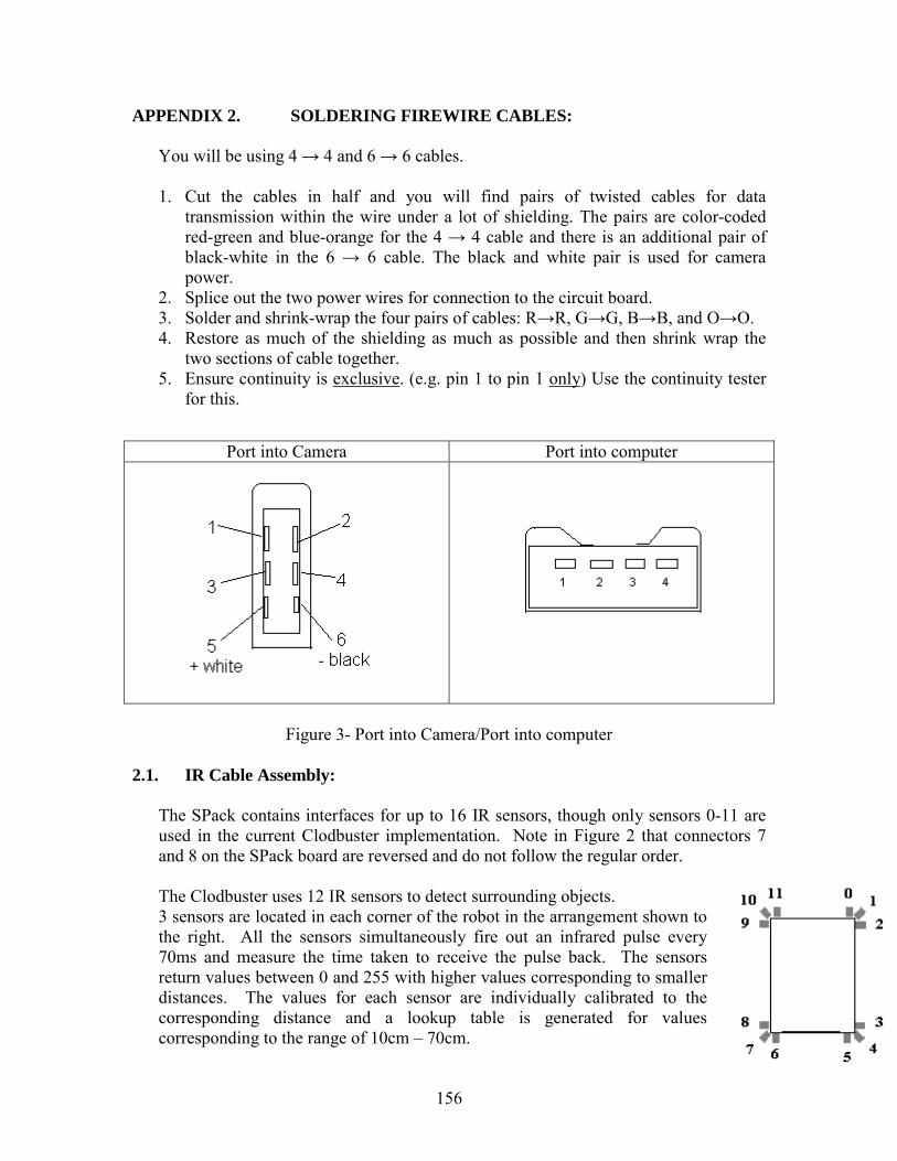
APPENDIX 2. SOLDERING FIREWIRE CABLES:
You will be using 4 → 4 and 6 → 6 cables.
1. Cut the cables in half and you will find pairs of twisted cables for data transmission within the wire under a lot of shielding. The pairs are color-coded red-green and blue-orange for the 4 → 4 cable and there is an additional pair of black-white in the 6 → 6 cable. The black and white pair is used for camera power.
2. Splice out the two power wires for connection to the circuit board. 3. Solder and shrink-wrap the four pairs of cables: R→R, G→G, B→B, and O→O. 4. Restore as much of the shielding as much as possible and then shrink wrap the
two sections of cable together. 5. Ensure continuity is exclusive. (e.g. pin 1 to pin 1 only) Use the continuity tester
for this.
Figure 3- Port into Camera/Port into computer
2.1. IR Cable Assembly:
The SPack contains interfaces for up to 16 IR sensors, though only sensors 0-11 are used in the current Clodbuster implementation. Note in Figure 2 that connectors 7 and 8 on the SPack board are reversed and do not follow the regular order.
The Clodbuster uses 12 IR sensors to detect surrounding objects. 3 sensors are located in each corner of the robot in the arrangement shown to the right. All the sensors simultaneously fire out an infrared pulse every 70ms and measure the time taken to receive the pulse back. The sensors return values between 0 and 255 with higher values corresponding to smaller distances. The values for each sensor are individually calibrated to the corresponding distance and a lookup table is generated for values corresponding to the range of 10cm – 70cm.
Port into Camera Port into computer
157
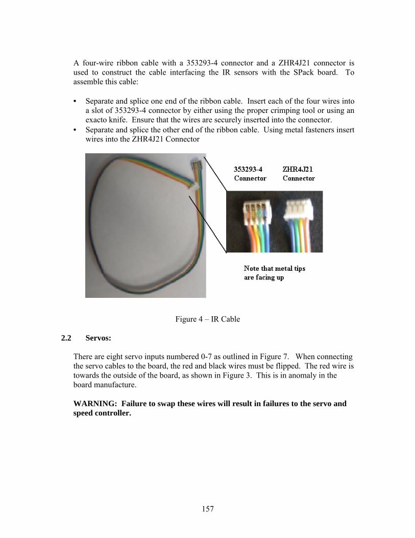
A four-wire ribbon cable with a 353293-4 connector and a ZHR4J21 connector is used to construct the cable interfacing the IR sensors with the SPack board. To assemble this cable:
• Separate and splice one end of the ribbon cable. Insert each of the four wires into
a slot of 353293-4 connector by either using the proper crimping tool or using an exacto knife. Ensure that the wires are securely inserted into the connector.
• Separate and splice the other end of the ribbon cable. Using metal fasteners insert wires into the ZHR4J21 Connector
Figure 4 – IR Cable
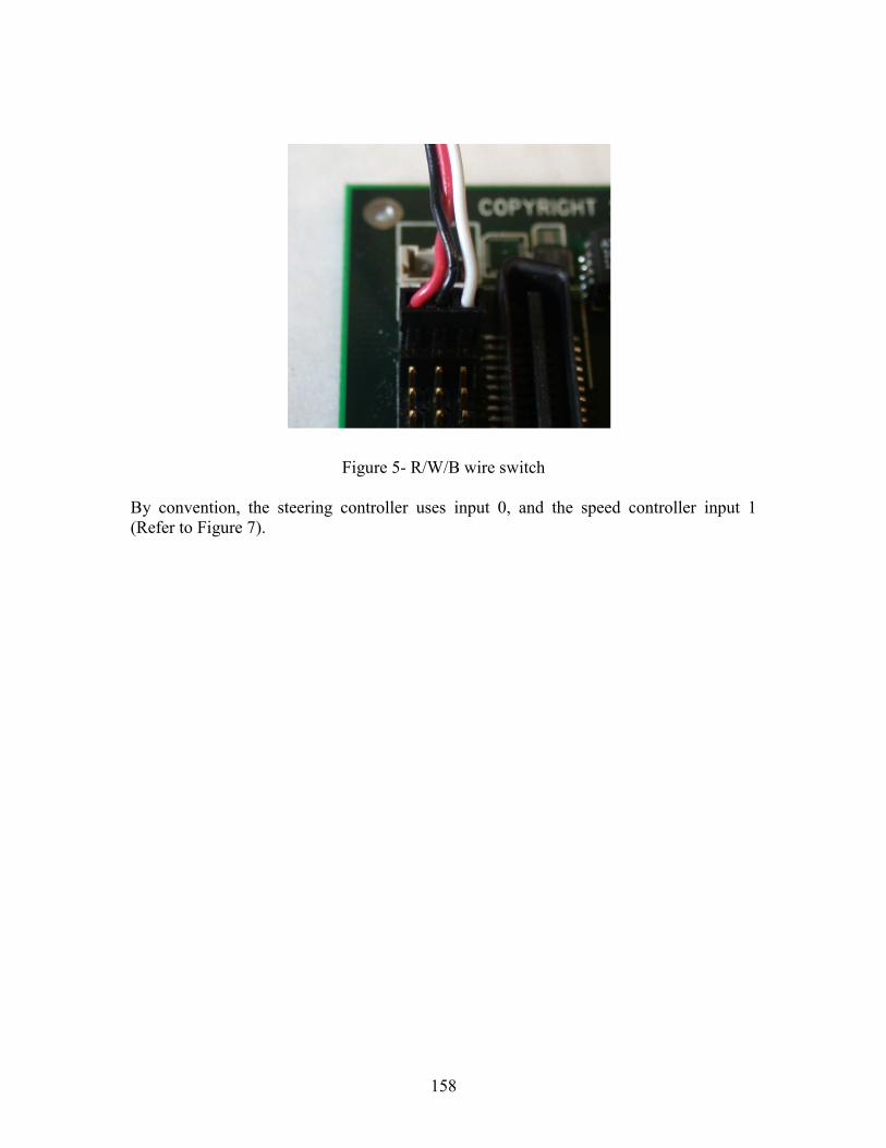
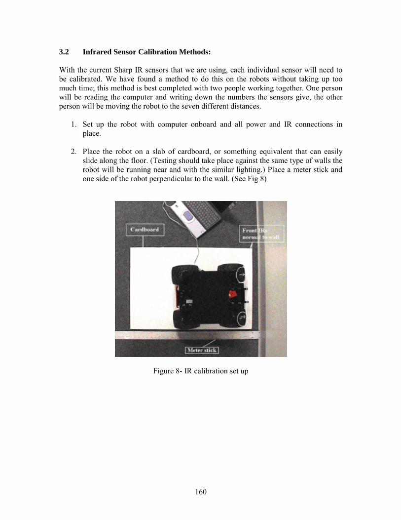
2.2 Servos:
There are eight servo inputs numbered 0-7 as outlined in Figure 7. When connecting the servo cables to the board, the red and black wires must be flipped. The red wire is towards the outside of the board, as shown in Figure 3. This is in anomaly in the board manufacture.
WARNING: Failure to swap these wires will result in failures to the servo and speed controller.
158
Figure 5- R/W/B wire switch By convention, the steering controller uses input 0, and the speed controller input 1 (Refer to Figure 7).
159
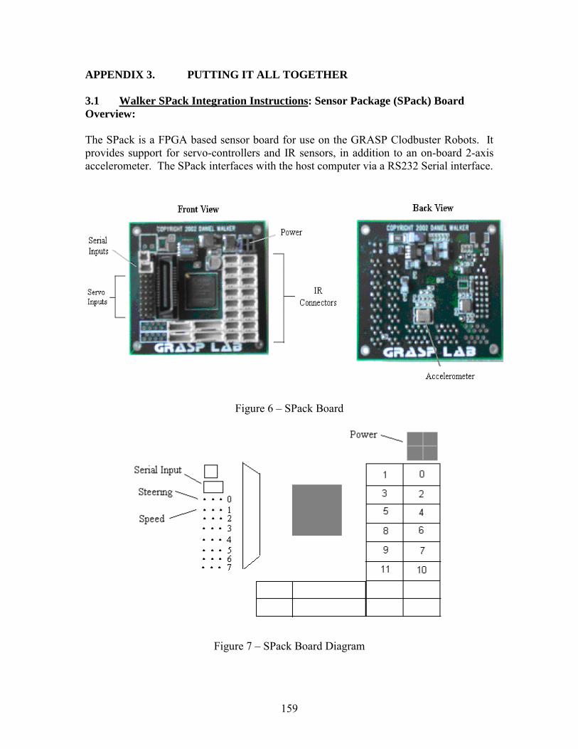
APPENDIX 3. PUTTING IT ALL TOGETHER 3.1 Walker SPack Integration Instructions: Sensor Package (SPack) Board Overview: The SPack is a FPGA based sensor board for use on the GRASP Clodbuster Robots. It provides support for servo-controllers and IR sensors, in addition to an on-board 2-axis accelerometer. The SPack interfaces with the host computer via a RS232 Serial interface.
Figure 6 – SPack Board
Figure 7 – SPack Board Diagram
160
3.2 Infrared Sensor Calibration Methods: With the current Sharp IR sensors that we are using, each individual sensor will need to be calibrated. We have found a method to do this on the robots without taking up too much time; this method is best completed with two people working together. One person will be reading the computer and writing down the numbers the sensors give, the other person will be moving the robot to the seven different distances.
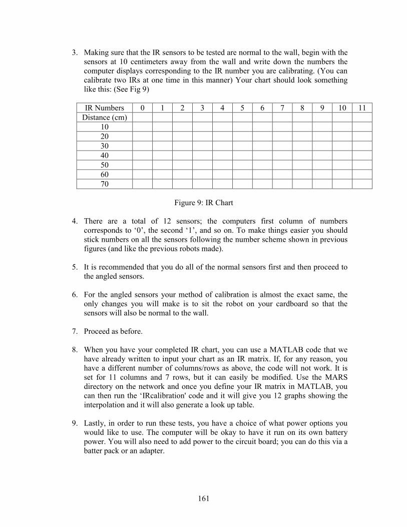
1. Set up the robot with computer onboard and all power and IR connections in place.
2. Place the robot on a slab of cardboard, or something equivalent that can easily
slide along the floor. (Testing should take place against the same type of walls the robot will be running near and with the similar lighting.) Place a meter stick and one side of the robot perpendicular to the wall. (See Fig 8)
Figure 8- IR calibration set up
161
3. Making sure that the IR sensors to be tested are normal to the wall, begin with the sensors at 10 centimeters away from the wall and write down the numbers the computer displays corresponding to the IR number you are calibrating. (You can calibrate two IRs at one time in this manner) Your chart should look something like this: (See Fig 9)
IR Numbers 0 1 2 3 4 5 6 7 8 9 10 11
Distance (cm) 10 20 30 40 50 60 70
Figure 9: IR Chart
4. There are a total of 12 sensors; the computers first column of numbers
corresponds to ‘0’, the second ‘1’, and so on. To make things easier you should stick numbers on all the sensors following the number scheme shown in previous figures (and like the previous robots made).
5. It is recommended that you do all of the normal sensors first and then proceed to
the angled sensors.
6. For the angled sensors your method of calibration is almost the exact same, the only changes you will make is to sit the robot on your cardboard so that the sensors will also be normal to the wall.
7. Proceed as before.
8. When you have your completed IR chart, you can use a MATLAB code that we
have already written to input your chart as an IR matrix. If, for any reason, you have a different number of columns/rows as above, the code will not work. It is set for 11 columns and 7 rows, but it can easily be modified. Use the MARS directory on the network and once you define your IR matrix in MATLAB, you can then run the ‘IRcalibration' code and it will give you 12 graphs showing the interpolation and it will also generate a look up table.
9. Lastly, in order to run these tests, you have a choice of what power options you
would like to use. The computer will be okay to have it run on its own battery power. You will also need to add power to the circuit board; you can do this via a batter pack or an adapter.
162
APPENDIX 4. EXTRA ADVICE 4.1. Things to Think about when Designing: This section is included just to give you an idea of some mistakes that were previously made so you will not have to make them again in order to learn from them.
• Circuit board placement o Needs to be easily accessible o Should be protected
• IR placement o With the current IRs that are used, objects up to 10 cm directly in front of
each IR can not be read accurately o If the sensors are placed approx 10 cm away from its edges, the IRs can
sense the perimeter of the robot • Computer Safety
o The computer needs to be secure with the ports that are needed easily accessible
o The notebook may be sensitive to overheating because of the conditions we run it in; make sure there is sufficient circulation around the computer
• Camera Stability o In the case you are using an omni-camera, information is best processed
with a picture that is not vibrating, make the camera mount as sturdy as possible
• Ease of Assembly/Disassembly o The testing phase of making the robots will call for a lot of assembly and
re-assembling the robot • Design Flexibility
o If your design is flexible to small changes (i.e. computer size change) you will not have to completely redesign the hardware to accommodate these changes
163
4.2 Anticipated Hold-ups Some warnings or frustrations you will come by while trying to get things done in GRASP lab:
• There is currently no hard organization of room 323. It would behoove you to clean it, organize, and become acquainted with it so that you have a better chance to know where things are later when you need them.
• There is always a shortage of parts o Nails/screws, nuts, bolts, etc.
• Tools that are available in room 323 o Epoxy/glue o Machines o Hand drills o Etc.
• Efficient use of “free time” o Construct IR connectors (there are never enough) o Review current hardware design, find areas that need improvement

164
MARS: MULTIPLE AUTONOMOUS ROBOTS ......................................................... 147 Kamela Watson (Mechanical Engineering) - Cornell University Advisor: Dr. Vijay Kumar ABSTRACT.................................................................................................................... 147
1. INTRODUCTION............................................................................................... 147 2. COORDINATED MOTION CONTROL ........................................................... 148
2.1 Cooperative Localization ............................................................................ 148 2.2 Formation Control ....................................................................................... 148 2.3 Cooperative Manipulation........................................................................... 149
3. SENSING............................................................................................................ 149 3.1 Cooperative Sensing.................................................................................... 149
3.1.1 Inertial Measurement Units................................................................. 149 3.2 Dead Reckoning .......................................................................................... 150 3.3 Range Finders.............................................................................................. 150 3.4 Global Positioning System (GPS)............................................................... 150
4. USE OF SENSOR TECHNOLOGIES ............................................................... 150 5. DISCUSSION AND CONCLUSIONS............................................................... 151 6. RECOMMENDATIONS .................................................................................... 151 7. ACKNOWLEDGMENTS................................................................................... 152 8. REFERENCES.................................................................................................... 152 9. APPENDICES..................................................................................................... 153 APPENDIX 1. ASSEMBLING WIRES AND PARTS........................................... 153
1.1 Power Connector Cable Assembly:............................................................. 153 1.2 Serial Input Cable Assembly:...................................................................... 154
APPENDIX 2. Soldering Firewire Cables:.............................................................. 156 2.1. IR Cable Assembly: .................................................................................... 156 2.2 Servos:......................................................................................................... 157
APPENDIX 3. PUTTING IT ALL TOGETHER .................................................... 159 3.1 Walker SPack Integration Instructions: Sensor Package (SPack) Board Overview: ................................................................................................................ 159 3.2 Infrared Sensor Calibration Methods: ......................................................... 160
APPENDIX 4. Extra Advice.................................................................................... 162 4.1. Things to Think about when Designing: ..................................................... 162 4.2 Anticipated Hold-ups .................................................................................. 163