Mark 70 Series - Jordan Valve · The Mark 70 Series is a line of pneumatically-operated ... •...
14
3L/T-2R/S33 Series Mark 70 Series Sliding Gate Control Valves The Mark 70 Series is a line of pneumatically-operated diaphragm control valves that combine multiple spring actuators with the precision of Jordan Valve's ad- vanced sliding gate seat for closer control and greater accuracy. Jordan's unique sliding gate control valve trim teams up with pressure, temperature pH, level, or flow con- trollers for fast response, long term reliability, and high levels of accuracy on steam, gas, liquid and chemical services. Consisting of a modulating disc and stationary plate, the sliding gate seat components are slotted with multiple orifices that align to provide the precise flow needed to maintain the process requirements. The valve strokes in a fraction of the travel required by conventional control valves for rapid correction of any deviation from the process setpoint. This brochure includes the following Series: • MK70: a line of pneumatically-operated dia- phragm control valves that combine multiple spring actuators with the precision of Jordan Valve's advanced sliding gate for closer control and greater metering accuracy • MK70PG: a pump governor with its control port connected to the pump discharge line. The valve throttles to maintain a constant pump discharge by controlling the steam flow to the pump. • MK701/702: for higher capacity requirements. • MK707: features an equal percentage flow characteristic. • MK711: a linear control valve in sizes up to 6" with Cv's to 395 • MK74: controls fugitive emissions while reducing the risks associated with toxic, corrosive, explo- sive and high temperature fluids Pneumatic Control Valves Mark 70 Sliding Gate Control Valves Jordan Valve a division of Richards Industries 3170 Wasson Road • Cincinnati, OH 45209 513.533.5600 • 800.543.7311 • 513.871.0105 (f) [email protected] • www.jordanvalve.com FEATURES • Totally enclosed multi-spring actuator – mini- mizes deadband and is field reversible without the use of special tools or additional parts • Compact design and simple construction – allows fast, simple installation and easy maintenance • Sliding gate seats provide: — Straight-through flow for reduced turbu- lence and quiet operation — Short stroke for fast response and accu- rate control — Easily interchangeable Cv's — Tight shutoff due to overlap of seat closure area • Stem packing is four times deeper then stem travel – for greater protection against leakage CRN Registration Number Available
Transcript of Mark 70 Series - Jordan Valve · The Mark 70 Series is a line of pneumatically-operated ... •...

3L/T-2R/S33 Series
Mark 70 SeriesSliding Gate Control Valves
The Mark 70 Series is a line of pneumatically-operated diaphragm control valves that combine multiple spring actuators with the precision of Jordan Valve's ad-vanced sliding gate seat for closer control and greater accuracy.
Jordan's unique sliding gate control valve trim teams up with pressure, temperature pH, level, or flow con-trollers for fast response, long term reliability, and high levels of accuracy on steam, gas, liquid and chemical services.
Consisting of a modulating disc and stationary plate, the sliding gate seat components are slotted with multiple orifices that align to provide the precise flow needed to maintain the process requirements. The valve strokes in a fraction of the travel required by conventional control valves for rapid correction of any deviation from the process setpoint.
This brochure includes the following Series:
• MK70: a line of pneumatically-operated dia-phragm control valves that combine multiple spring actuators with the precision of Jordan Valve's advanced sliding gate for closer control and greater metering accuracy
• MK70PG: a pump governor with its control port connected to the pump discharge line. The valve throttles to maintain a constant pump discharge by controlling the steam flow to the pump.
• MK701/702: for higher capacity requirements.
• MK707: features an equal percentage flow characteristic.
• MK711: a linear control valve in sizes up to 6" with Cv's to 395
• MK74: controls fugitive emissions while reducing the risks associated with toxic, corrosive, explo-sive and high temperature fluids
Pneum
atic Co
ntrol V
alves
Mark 7
0 S
liding
Gate
Co
ntrol V
alves
Jordan Valve a division of Richards Industries 3170 Wasson Road • Cincinnati, OH 45209 513.533.5600 • 800.543.7311 • 513.871.0105 (f)[email protected] • www.jordanvalve.com
Features
• Totally enclosed multi-spring actuator – mini-mizes deadband and is field reversible without the use of special tools or additional parts
• Compact design and simple construction – allows fast, simple installation and easy maintenance
• Sliding gate seats provide: — Straight-through flow for reduced turbu-
lence and quiet operation — Short stroke for fast response and accu-
rate control — Easily interchangeable Cv's — Tight shutoff due to overlap of seat closure
area
• Stem packing is four times deeper then stem travel – for greater protection against leakage
CRN Registration Number Available

-2-
Mark 70 Sliding gate Control ValVeS
Sizes: (note: 1/4" & 3/8" sizes use 1/2" body with reducers)• Mark 70/70PG: 1/4" through 2" (DN8 through DN50)• Mark 707: 1/2" through 6" (DN8 through DN150)• Mark 711: 2-1/2" through 6" (DN65 through DN150)
End Connections• Threaded (NPT, BSPT, BSPP – through 2" sizes/DN50)• ANSI Flanges (150#, 300#)• DIN Flanges (PN10/16, PN25/40)
Body Materials• Ductile Iron• Bronze (1/2" – 2"/DN15 - DN50)• Carbon Steel (WCB)• Stainless Steel (CF8M)
Trim Materials• 303SS for CI and DI body valves• 316SS for SS body valves
Seat Materials• Jorcote on SST – standard
Yoke Material: Cast Iron Actuator: Steel
speciFications
Diaphragm: Buna-N (standard to 200°F/93°C)
Stem Packing: spring-loaded Teflon (to 450°F/232°C); Graphite (to 1200°F/649°C)
Service: Steam, water, oil, gas, air and chemicals
Shutoff: ANSI Class IV
Ranges• Mark 70/707/711: 3-15, 3-9, 9-15, 6-30 psi
(0,21-1,03; 0,21-0,62; 0,62-1,03; 0,41-2,07 bar)• Mark 70PG: consult factory for ranges
Action• Direct (air signal closes valve)• Reverse (air signal opens valve)
Positioner: side or top-mounted positioners are avail-able to overcome the normal hysteresis for a control valve and actuator, and to ensure that the valve stem position is always directly proportional to the control valve command signal. See the Positioner section for more details.
Rangeability• MK70: 1/2" – 1-1/2", 100:1• MK70: 2", >200:1• MK711: 2-1/2" – 3", >200:1• MK711: 4" – 6", 100:1• MK707: all sizes 100:1

-3-
Mark 70 Sliding gate Control ValVeS
cv values and MaxiMuM allowable diFFerential pressure ratings
• Mark 70Flow Coefficient
Valve Size Seat Material
Maximum Differential Pressure (PSI)
Cv Kv
Std. 35M Actua-tor
35M with Positioner
Optional 55M Actuator
55M with Positioner
Optional 85M Actuator
PSI BAR PSI BAR PSI BAR PSI BAR PSI BAR
2.5 or 4.4
2,2 or 3,8
1/2" & 3/4" (DN15 &
20)
SST 125 8,6 175 12,1 175 12,1 175 12,1 175 12,1
Jorcote 250 17,2 500 34,5 350 24,1 700 48,3 550 37,9
6.4 or 9.5
5,5 or 8,2
1" & 1-1/4"(DN25 &
32)
SST 100 6,9 150 10,3 150 10,3 150 10,3 150 10,3
Jorcote 150 10,3 300 20,7 225 15,5 425 29,3 350 24,1
15 12,9 1-1/2"(DN40)
SST 75 5,2 125 8,6 100 6,9 125 8,6 125 8,6
Jorcote 125 8,6 250 17,2 175 12,1 350 24,1 275 19,0
25 or 30
21,5 or 25,8
2"(DN50)
SST 75 5,2 125 8,6 100 6,9 125 8,6 125 8,6
Jorcote 125 8,6 250 17,2 175 12,1 350 24,1 275 19,0
Based on 45 psi (3,1 bar) to actuator or psi
• Mark 711 — Standard Actuator: 2-1/2" – 3": 55M; 4" – 6" 85M
Flow Coefficient Cv (Kv) Valve Size Seat
MaterialMaximum ∆P, PSI* (BAR)
Standard w/Positioner
85 (73) 2-1/2" (DN65) Jorcote 50 (3,5) 275 (19)
130 (112) 3" (DN80) Jorcote 50 (3,5) 275 (19)
200 (172) 4" (DN100) Jorcote 50 (3,5) 325 (22)
395 (340) 6" (DN150) Jorcote 50 (3,5) 225 (16)
* Higher ∆P's available with optional larger actuators
• Mark 707 — Standard Actuator: 1/2" – 2": 35M; 2" - 8": 55M
Flow Coefficient Cv (Kv) Valve Size Seat
Material
Maximum ∆P* PSI (BAR)
Standard Actuator w/Positioner
2.5 (2,2) 1/2" (DN15) Jorcote 250 (17,2) 500 (34,5)
4.4, 6.4 or 9.5 (3,8; 5,5; or 8,2) 3/4" (DN20) Jorcote 150 (10,3) 300 (20,7)
11.5 (9,9) 1" (DN25)SST 100 (6,9) 175 (6,9)
Jorcote 150 (10,3) 300 (13,8)
13 (11,2) 1-1/4" (DN32)
SST 100 (6,9) 175 (6,9)
Jorcote 150 (10,3) 300 (23,8)
22 (18,9) 1-1/2" (DN40)
SST 100 (6,9) 150 (6,9)
Jorcote 150 (10,3) 150 (6,9)
34 (29,2) 2" (DN50)SST 100 (6,9) 150 (6,9)
Jorcote 150 (10,3) 150 (6,9)
60 (51,6) 2-1/2" (DN65) Jorcote 50 (3,5) 275 (19,0)
80 (68,8) 3" (DN80) Jorcote 50 (3,5) 275 (19,0)
130 (112) 4" (DN100) Jorcote 50 (3,5) 225 (15,5)
230 (198) 6" (DN150) Jorcote 50 (3,5) 150 (6,9)
Low Flow: reduced Cv's can be used in any size valve as long as it is a smaller value than is standard for that size. In addition, these low flow Cv's can be provided:
1.6 0.84 0.42 0.21 0.08 0.04
0,02 0,008 0,004 0,002 0,0008 (N/A in 316SS)

Mark 70 Sliding gate Control ValVeS
MaxiMuM working pressures & teMperatures
• Mark 70 & Mark 707 (1/2" – 2") (DN15 - DN50)Maximum Pressure @ 100°F, PSI/°F
PackingDI Body BRZ Body CS Body SST Body
150# 300# TE 150# 300# TE 150# 300# TE 150# 300# TE
Any 250 640 988 225 500 500 285 740 1480 275 720 1440
Pressure @ Maximum Temperature, PSI/°F
TEF 170/450 495/450 808/450 150/450 325/450 325/450 170/450 600/450 1200/450 170/450 480/450 955/450
GRAF 125/650 450/650 715/650 150/500 325/500 325/500 125/650 535/650 1075/650 125/650 445/650 890/650
Maximum Pressure @ 38°C, BAR/°
PackingDI Body BRZ Body CS Body SST Body
150# 300# TE 150# 300# TE 150# 300# TE 150# 300# TE
Any 17 44 68 16 34 34 20 51 102 19 50 99
Pressure @ Maximum Temperature, PSI/°C
TEF 12/232 34/232 56/232 10/232 22/232 22/232 12/232 41/232 83/232 12/232 33/232 66/232
GRAF 9/343 31/343 49/343 10/343 22/343 22/343 9/343 37/343 74/343 9/343 31/343 61/343
• Mark 711 & Mark 707 (2-1/2" – 6") (DN65 - DN150_Maximum Pressure @ 100°F, PSI/°F
PackingDI Body BRZ Body CS Body SST Body
150# 300# TE 150# 300# TE 150# 300# TE 150# 300# TE
Any 250 640 — — — — 285 740 — 275 720 —
Pressure @ Maximum Temperature, PSI/°F
TEF 170/450 495/450 — 150/450 325/450 — 170/450 600/450 — 170/450 480/450 —
GRAF 125/650 450/650 — 150/500 325/500 — 125/650 535/650 — 125/650 445/650 —
Maximum Pressure @ 38°C, BAR/°
PackingDI Body BRZ Body CS Body SST Body
150# 300# TE 150# 300# TE 150# 300# TE 150# 300# TE
Any 17 44 — — — — 20 51 — 19 50 —
Pressure @ Maximum Temperature, PSI/°F
TEF 12/232 34/232 — 10/232 22/232 — 12/232 41/232 — 12/232 33/232 —
GRAF 9/343 31/343 — 10/343 22/343 — 9/343 37/343 — 9/343 31/343 —
-4-

Mark 70 Sliding gate Control ValVeS
pressure-teMperature charts – Mk70, Mk74
Pres
sure
(PSI
)
0
100
200
300
400
500
600
0 50 100 150 200 250 300 350 400 450 500
Temperature °F
150 CI300/TE BR
• Cast Iron • Bronze
Pres
sure
(PSI
)
0
100
200
300
400
500
600
0 100 200 300 400 500
Temperature °F
150 CI300/TE BR
600
• Ductile Iron
Pres
sure
(PSI
)
0
100
200
300
400
800900
500
600
700
10001100
• Carbon Steel
Pres
sure
(PSI
)
0
200
400
600
800
1600
1400
1200
1000
0 100 200 300 400 500 600 700Temperature °F
150 DI
300 DI
600 DI/TE/DI
SS/Has C Bellows
Std. BoltPTFE Pack.
0 100 200 300 400 500 600 700Temperature °F
150 CS
300 CS
600 CS/TE/SW
SS/Has C Bellows
Std. BoltPTFE Pack.
• Stainless Steel
Pres
sure
(PSI
)400
0
200
400
600
800
1400
1600
0 100 200 300 500 600 700Temperature °F
150 SS
300 SS
600 SS/TE
SS/Has C Bellows
Std. Bolt
PTFE Pack.
1200
1000
-5-

Mark 70 Sliding gate Control ValVeS
diMensions
B
C
A1
A
D
1/4" NPT• Mark 70: Flanged Ends
Size ANSI Flange
Dimensions (inches) Weight(lbs)A1 B C D
1/2"150# 7.25 9.38 2.18 9.50 26
300# 7.50 9.38 2.18 9.50 28
3/4"150# 7.25 9.38 2.18 9.50 26
300# 7.62 9.38 2.18 9.50 28
1"150# 7.25 9.62 2.62 9.50 30
300# 7.75 9.62 2.62 9.50 32
1-1/4"150# 7.87 9.87 2.62 9.50 28
300# 8.37 9.87 2.62 9.50 30
1-1/2"150# 8.75 9.87 2.75 9.50 30
300# 9.25 9.87 2.75 9.50 32
2"150# 10.00 10.00 3.00 9.50 34
300# 10.50 10.00 3.00 9.50 36
• Mark 70: Flanged Ends (metric)
Size ANSI PNDimensions (mm) Weight
(kgs)A1 B C D
DN1510/16 130 238 55 241 11,8
25/40 130 238 55 241 12,7
DN2010/16 150 238 55 241 11,8
25/40 150 238 55 241 12,7
DN2510/16 160 244 67 241 12,7
25/40 160 244 67 241 13,6
DN3210/16 180 251 67 241 12,7
25/40 180 251 67 241 13,6
DN4010/16 200 251 70 241 13,6
25/40 200 251 70 241 14,5
DN5010/16 230 254 76 241 14,8
25/40 230 254 76 241 16,3
-6-
• Mark 70: Threaded Ends
Size MaterialDimensions (inches) Weight
(lbs)A B C D
1/2" & 3/4"
DI/BRZ 3.62 9.38 2.18 9.50 24
CS/SS 3.65 9.38 2.18 9.50 24
1"DI/BRZ 4.12 9.62 2.62 9.50 26
CS/SS 4.12 9.62 2.62 9.50 28
1-1/4" DI/BRZ 4.12 9.87 2.62 9.50 26
1-1/2"DI/BRZ 4.50 9.87 2.62 9.50 27
CS/SS 4.65 9.87 2.75 9.50 28
2"DI/BRZ 4.50 10.00 2.62 9.50 29
CS/SS 5.50 10.00 3.00 9.50 32
• Mark 70: Threaded Ends (metric)
Size MaterialDimensions (mm) Weight
(kgs)A B C D
DN15 & 20"
DI/BRZ 92 238 55 241 10,9
CS/SS 93 238 55 241 10,9
DN25DI/BRZ 105 244 67 241 11,8
CS/SS 105 244 67 241 12,7
DN32 DI/BRZ 105 251 67 241 11,8
DN40DI/BRZ 114 251 67 241 12,2
CS/SS 118 251 70 241 12,7
DN50DI/BRZ 114 254 67 241 13,2
CS/SS 140 254 76 241 14,5

Mark 70 Sliding gate Control ValVeS
diMensions
C
A1
A
D1/4" NPT
• Mark 707: Threaded Ends
Size MaterialDimensions (inches) Weight
(lbs)A B C D
1/2" DI/BRZ 3.62 9.38 2.18 9.50 24
CS/SS 3.65 9.38 2.18 9.50 24
3/4"DI/BRZ 4.12 10.82 2.62 12.50 37
CS/SS 4.12 10.82 2.62 12.50 39
1"DI/BRZ 4.12 10.82 2.62 12.50 37
CS/SS 4.12 10.82 2.62 12.50 39
1-1/4" DI/BRZ 4.12 11.07 2.62 12.50 37
1-1/2"DI/BRZ 4.50 11.07 2.62 12.50 40
CS/SS 4.65 11.20 3.00 12.50 43
2"DI/BRZ 4.50 11.20 2.62 12.50 40
CS/SS 5.50 11.20 3.00 12.50 43
-7-
• Mark 707: Threaded Ends (metric)
Size MaterialDimensions (mm) Weight
(kgs)A B C D
DN15DI/BRZ 92 238 55 241 11
CS/SS 93 238 55 241 11
DN20DI/BRZ 105 205 67 318 17
CS/SS 105 275 67 318 18
DN25DI/BRZ 105 205 67 318 17
CS/SS 105 275 67 318 18
DN32 DI/BRZ 105 281 67 318 17
DN40DI/BRZ 114 281 67 318 18
CS/SS 140 284 76 318 20
DN50DI/BRZ 114 284 67 318 18
CS/SS 140 284 76 318 20
• Mark 707 & Mark 711: Flanged Ends
Size ANSI Flange
Dimensions (inches) Weight(lbs)A1 B C D
2-1/2"125/150# 10.87
19.50 5.12 15.00 210250/300# 11.50
3"125/150# 11.75
19.50 5.37 15.00 255250/300# 12.50
4"125/150# 13.87
20.75 6.00 15.00 325250/300# 14.50
6"125/150# 17.75
21.50 7.00 15.00 410250/300# 18.62
• Mark 707 & Mark 711: Flanged Ends (metric)
Size ANSI Flange
Dimensions (mm) Weight(kgs)A1 B C D
DN6510/16 276
495 130 381 9525/40 290
DN8010/16 298
495 136 381 10225/40 310
DN10010/16 350
527 152 381 15225/40 368
DN15010/16 457
546 178 381 18625/40 480
D
1/4" NPT
B
C
A

ordering scheMatic
Model Size Body Mat'l/
1 2 3 4 5 6 7 8 9 10 11 12 13 14 15 16 17
Mark 70 Sliding gate Control ValVeS
Model70 Standard
70SP Standard with Side Positioner70TP Standard with Top Positioner707 Equal Percentage
707SP Equal Percentage with Side Positioner707TP Equal Percentage with Top Positioner
711 Linear711SP Linear with Side Positioner711TP Linear with Top Positioner
Size050 1/2" (DN15) 200 2" (DN50)075 3/4" (DN20) 250 2-1/2" (DN65)100 1" (DN25) 300 3" (DN80)125 1-1/4" (DN32) 400 4" (DN100)150 1-1/2" (DN40) 600 6" (DN150)
Body MaterialDI Ductile IronBR BronzeCS Carbon Steel (WCB)S6 Stainless Steel (CF8M)
1 & 2 End ConnectionsPT NPTBT BSPTI5 150# IFE DI above 2" or CS or SST valvesF5 150# FE DI below 2-1/2" or BRI7 PN1`0 IFE DI above 2" or CS or SST valvesF7 PN10 FE DI below 2-1/2" or BRI6 PN16 IFE DI above 2" or CS or SST valvesF6 PN16 FE DI below 2-1/2" or BRBP BSPPSW FSWI3 300# IFE DI above 2" or CS or SST valvesF3 300# FE DI below 2-1/2" or BRI8 PN25 IFE DI above 2" or CS or SST valvesF8 PN25 FE DI below 2-1/2" or BRI4 PN40 IFE DI above 2" or CS or SST valvesF4 PN40 FE DI below 2-1/2" BR
6Cv
MK70 & MK711 MK7071 0.21 (0,28) A 25 (22) 5 2.5 (2,2)2 0.42 (0,36) B 30 (26) 6 4.4 (3,8)3 0.84 (0,72) C 50 (43) N 11.5 (9,9)4 1.6 (1,4) F 85 (73) P 13 (11,2)5 2.5 (2,2) G 115 (99) S 22 (19)6 4.4 (3,8) H 130 (112) U 34 (29)7 6.4 (5,5) I 200 (172) 1 60 (52)8 9.5 (8,2) J 395 (341) 2 80 (69)9 15 (13,0) H 130 (112)
3 230 (199)
7, 8, 9, 10, 11, 12Mark 70 Series Range & Actuator
Range ActuatorN3Q3N3 3-15 DIR
35MQ3Q3N3 3-15 REV
7, 8, 9, 10, 11, 12All Mark 70 Models Range & Actuator
Range ActuatorA3B3A3 3-15 DIR
35MB3B3A3 3-15 REVG3B3A3 6-30 DIRH3B3A3 6-30 REVA5B5A5 3-15 DIR
55MB5B5A5 3-15 REVG5B5A5 6-30 DIRH5B5A5 6-30 REVA8B8A8 3-15 DIR
85MB8B8A8 3-15 REVG8B8A8 6-30 DIRH8B8A8 6-30 REV
-8-
5 Seat MaterialV 303SS/JorcoteW 316SS/Jorcote
3 & 4 TrimT3 303SS/TFE PkgT6 316SS/TFE PkgI3 303SS/GraphiteI6 316SS/Graphite

ordering scheMatic, cont.
Model Size Body Mat'l/
1 2 3 4 5 6 7 8 9 10 11 12 13 14 15 16 17
Mark 70 Sliding gate Control ValVeS
13 & 14 Accessories00 NoneAR Air RegulatorH3 Handwheel 35M ActuatorH5 Handwheel 55M ActuatorH8 Handwheel 85M ActuatorS6 316SS Bolting
15 ActionD Air-to-CloseR AIr-to-Open
16 I/P0 None3 I/P 35M Actuator5 I/P 55M Actuator8 I/P 85M Actuator
-9-
17 SMP
0 None
A SMP DIR/REV 3-15
B SMP DIR/REV 3-9
C SMP DIR/REV 9-15
D SMP/IP DIR/REV 4-20
E SMP/IP DIR/REV 4-12
F SMP/IP DIR/REV 12-20
G MK16IQ-S DIR/REV 4-20 (Hart & FM-App)
H MK16IQ-B DIR/REV 4-20 (with gauges)
J MK16IQ-FF DIR/REV 4-20 (Fieldbus w/ gauges)
Z Non-Standard

3L/T-2R/S33 Series
Mark 701/702 SeriesHigh-Flow and Super High-Flow Control Valves
The Mark 701/702 high-flow and super high-flow sliding gate control valves provide:
• Shorter Stroke than a globe or plug-style valve — Faster response — Longer packing and seat life — Stem packing is four times deeper than stem
travel – for greater protection against leakage — Smaller and lighter weight than globe-style
valves
• Straight through flow — Less turbulence, erosion and noise — Fewer spare parts — Self-cleaning seats — No gaskets or o-rings
• Ease of maintenance — Interchangeable seats and Cv's — Fewer spare parts — Self-cleaning seats — No gaskets or o-rings
speciFications
Sizes: 1/2" through 2" (DN15 through DN50)
End Connections• Threaded (NPT, BSPT, BSPP)• ANSI Flanges (150#, 300#)• DIN Flanges (PN10/16; PN25/40)
Body Materials• Ductile Iron• Bronze• Carbon Steel (WCB)• Stainless Steel (CF8M)
Trim Materials• 303SS for CI, DI, BRZ & CS body valves• 316SS for SS body valves
Seat Materials• Jorcote on SST – standard
Yoke: Cast Iron
Actuator: Steel
Diaphragm: Buna-N (standard, to 200°/93°C)
Stem Packing: Spring-loaded Teflon (to 450°F/232°C); Graphite (to 1200°/649°C)
Service: steam, water, oil, gas, air and chemicals
Shutoff: ANSI Class IV
Ranges: 3-15, 3-9, 9-15, 6-30 psi (0,21-1,03; 0,21-0,62; 0,62-1,03; 0,41-2,1 bar)
Action• Direct (air signal closes valve)• Reverse (air signal opens valve)
Positioner: Side or top mounted positioners are available to ensure that the valve stem position is always directly proportional to the control system output signal. See the Positioner section for more details.
Body Rating• Ductile Iron up to 988 psi (68,1 bar) @ 100°F (38°C)
and 715 psi (49,3 bar) @ 650°F (343°C)• Carbon Steel and Stainless Steel up to 1440 psi (99
bar) @ 100°F (38°C) and 890 psi (61 bar) @ 650°F (343°C)
• Bronze up to 500 psi (35 bar) @ 100°F (38°C) and 325 psi (22 bar) @ 500°F (260°C)
• Temperature limit of -20°F (-29°C) on all materials; for other temperatures, consult factory-10-
Mark 701/702 HigH Flow & Super HigH Flow Sliding gate Control ValVeS
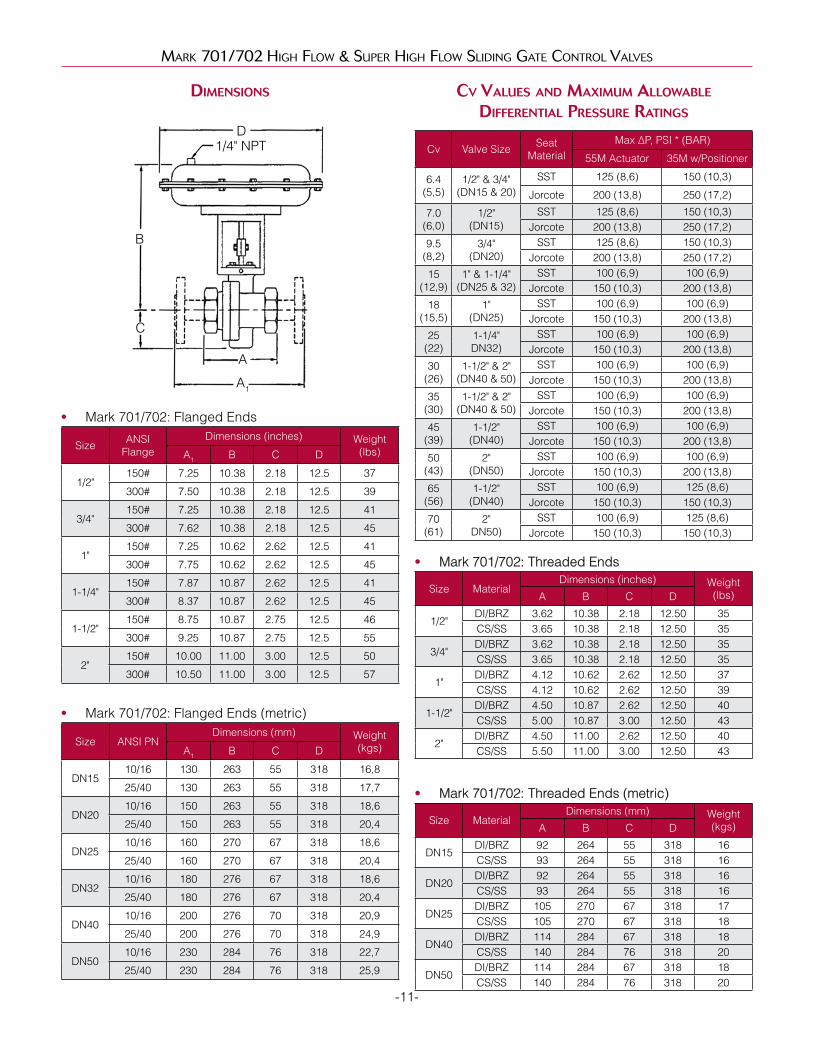
diMensions
B
C
A1
A
D1/4" NPT
• Mark 701/702: Flanged Ends
Size ANSI Flange
Dimensions (inches) Weight(lbs)A1 B C D
1/2"150# 7.25 10.38 2.18 12.5 37
300# 7.50 10.38 2.18 12.5 39
3/4"150# 7.25 10.38 2.18 12.5 41
300# 7.62 10.38 2.18 12.5 45
1"150# 7.25 10.62 2.62 12.5 41
300# 7.75 10.62 2.62 12.5 45
1-1/4"150# 7.87 10.87 2.62 12.5 41
300# 8.37 10.87 2.62 12.5 45
1-1/2"150# 8.75 10.87 2.75 12.5 46
300# 9.25 10.87 2.75 12.5 55
2"150# 10.00 11.00 3.00 12.5 50
300# 10.50 11.00 3.00 12.5 57
• Mark 701/702: Flanged Ends (metric)
Size ANSI PNDimensions (mm) Weight
(kgs)A1 B C D
DN1510/16 130 263 55 318 16,8
25/40 130 263 55 318 17,7
DN2010/16 150 263 55 318 18,6
25/40 150 263 55 318 20,4
DN2510/16 160 270 67 318 18,6
25/40 160 270 67 318 20,4
DN3210/16 180 276 67 318 18,6
25/40 180 276 67 318 20,4
DN4010/16 200 276 70 318 20,9
25/40 200 276 70 318 24,9
DN5010/16 230 284 76 318 22,7
25/40 230 284 76 318 25,9
cv values and MaxiMuM allowable diFFerential pressure ratings
Cv Valve Size Seat Material
Max ∆P, PSI * (BAR)
55M Actuator 35M w/Positioner
6.4 (5,5)
1/2" & 3/4" (DN15 & 20)
SST 125 (8,6) 150 (10,3)
Jorcote 200 (13,8) 250 (17,2)
7.0 (6,0)
1/2" (DN15)
SST 125 (8,6) 150 (10,3)Jorcote 200 (13,8) 250 (17,2)
9.5 (8,2)
3/4" (DN20)
SST 125 (8,6) 150 (10,3)Jorcote 200 (13,8) 250 (17,2)
15 (12,9)
1" & 1-1/4" (DN25 & 32)
SST 100 (6,9) 100 (6,9)Jorcote 150 (10,3) 200 (13,8)
18 (15,5)
1" (DN25)
SST 100 (6,9) 100 (6,9)Jorcote 150 (10,3) 200 (13,8)
25 (22)
1-1/4" DN32)
SST 100 (6,9) 100 (6,9)Jorcote 150 (10,3) 200 (13,8)
30 (26)
1-1/2" & 2" (DN40 & 50)
SST 100 (6,9) 100 (6,9)Jorcote 150 (10,3) 200 (13,8)
35 (30)
1-1/2" & 2" (DN40 & 50)
SST 100 (6,9) 100 (6,9)Jorcote 150 (10,3) 200 (13,8)
45 (39)
1-1/2" (DN40)
SST 100 (6,9) 100 (6,9)Jorcote 150 (10,3) 200 (13,8)
50 (43)
2" (DN50)
SST 100 (6,9) 100 (6,9)Jorcote 150 (10,3) 200 (13,8)
65 (56)
1-1/2" (DN40)
SST 100 (6,9) 125 (8,6)Jorcote 150 (10,3) 150 (10,3)
70 (61)
2" DN50)
SST 100 (6,9) 125 (8,6)Jorcote 150 (10,3) 150 (10,3)
• Mark 701/702: Threaded Ends
Size MaterialDimensions (inches) Weight
(lbs)A B C D
1/2"DI/BRZ 3.62 10.38 2.18 12.50 35CS/SS 3.65 10.38 2.18 12.50 35
3/4"DI/BRZ 3.62 10.38 2.18 12.50 35CS/SS 3.65 10.38 2.18 12.50 35
1"DI/BRZ 4.12 10.62 2.62 12.50 37CS/SS 4.12 10.62 2.62 12.50 39
1-1/2"DI/BRZ 4.50 10.87 2.62 12.50 40CS/SS 5.00 10.87 3.00 12.50 43
2"DI/BRZ 4.50 11.00 2.62 12.50 40CS/SS 5.50 11.00 3.00 12.50 43
• Mark 701/702: Threaded Ends (metric)
Size MaterialDimensions (mm) Weight
(kgs)A B C D
DN15DI/BRZ 92 264 55 318 16CS/SS 93 264 55 318 16
DN20DI/BRZ 92 264 55 318 16CS/SS 93 264 55 318 16
DN25DI/BRZ 105 270 67 318 17CS/SS 105 270 67 318 18
DN40DI/BRZ 114 284 67 318 18CS/SS 140 284 76 318 20
DN50DI/BRZ 114 284 67 318 18CS/SS 140 284 76 318 20
-11-

0 100 200 300 400 500TEmpERaTuRE °F
150 CI300/TE BR
6000 100 200 300 400 500 600 700TEmpERaTuRE °F
150 DI
300 DI
600/TE/SW SS
SS/HaS C BElloWS
STD. BolTpTFE paCk.
0 100 200 300 400 500 600 700TEmpERaTuRE °F
150 DI
300 DI
600 DI/TE/DI
SS/HaS C BElloWS
STD. BolTpTFE paCk.
Mark 701/702 HigH Flow & Super HigH Flow Sliding gate Control ValVeS
pressure-teMperature charts – Mk701/702
pRES
SuR
E (p
SI)
0
100
200
300
400
500
600
• Bronze
• Ductile Iron
pRES
SuR
E (p
SI)
0100200
300
400
800
900
500
600
700
10001100
• Carbon Steel
pRES
SuR
E (p
SI)
0
200
400
600
800
1600
1400
1200
1000
• Stainless Steel
pRES
SuR
E (p
SI)
0
200
400
600
800
0 100 200 300 400 500 600 700TEmpERaTuRE °F
150 DI
300 DI
600 DI/TE/DI
SS/HaS C BElloWS
STD. BolT
pTFE paCk.
1400
1600
1200
1000
-12-

ordering scheMatic
Model Size Body Mat'l/
1 2 3 4 5 6 7 8 9 10 11 12 13 14 15 16 17
Mark 701/702 HigH Flow & Super HigH Flow Sliding gate Control ValVeS
Model701 High Flow
701SP High Flow with Side Positioner701TP High Flow with Top Positioner
702 Super High Flow702SP Super High Flow with Side Positioner702TP Super High Flow with Top Positioner
Size050 1/2" (DN15)075 3/4" (DN20)100 1" (DN25)125 1-1/4" (DN32)150 1-1/2" (DN40)200 2" (DN50)
Body MaterialDI Ductile IronBR BronzeCS Carbon Steel (WCB)S6 Stainless Steel (CF8M)
1 & 2 End ConnectionsPT NPTBT BSPTI5 150# IFE DI above 2" or CS or SST valvesF5 150# FE DI below 2-1/2" or BRI7 PN10 IFE DI above 2" or CS or SST valvesF7 PN10 FE DI below 2-1/2" or BRI6 PN16 IFE DI above 2" or CS or SST valvesF6 PN16 FE DI below 2-1/2" or BRBP BSPPSW FSWI3 300# IFE DI above 2" or CS or SST valvesF3 300# FE DI below 2-1/2" or BRI8 PN25 IFE DI above 2" or CS or SST valvesF8 PN25 FE DI below 2-1/2" or SST valvesI4 PN40 IFE DI above 2" or CS or SST valvesF4 PN40 FE DI below 2-1/2" or BR
6 Cv7 6.4 (5,5) A 25 (22)L 6.4 (5,5) B 30 (26)M 9.0 (7,8) V 35 (31)8 9.5 (8,2) W 45 (39)9 15 (13) C 50 (43)R 18 (15,5) Y 65 (56)T 24 (21) E 70 (60)
7, 8, 9, 10, 11, 12Range & Actuator
Range ActuatorA3B3A3 3-15 DIR
35MB3B3A3 3-15 REVG3B3A3 6-30 DIRH3B3A3 6-30 REVA5B5A5 3-15 DIR
55MB5B5A5 3-15 REVG5B5A5 6-30 DIRH5B5A5 6-30 REVA8B8A8 3-15 DIR
85MB8B8A8 3-15 REVG8B8A8 6-30 DIRH8B8A8 6-30 REV
-13-
5 Seat MaterialA 303SSTB 316SSTV 303SS/JorcoteW 316SS/Jorcote
3 & 4 TrimT3 303SS/TFE PkgT6 316SS/TFE Pkg

ordering scheMatic, cont.
Mark 701/702 HigH Flow & Super HigH Flow Sliding gate Control ValVeS
13 & 14 Accessories00 NoneAR Air RegulatorH3 Handwheel 35M ActuatorH5 Handwheel 55M ActuatorH8 Handwheel 85M ActuatorS6 316SS Bolting
15 ActionD Air-to-CloseR AIr-to-Open
16 I/P0 None3 I/P 35M Actuator5 I/P 55M Actuator8 I/P 85M Actuator
MK70/0517
17 SMP
0 None
A SMP DIR/REV 3-15
B SMP DIR/REV 3-9
C SMP DIR/REV 9-15
D SMP/IP DIR/REV 4-20
E SMP/IP DIR/REV 4-12
F SMP/IP DIR/REV 12-20
G MK16IQ-S DIR/REV 4-20 (Hart & FM-App)
H MK16IQ-B DIR/REV 4-20 (with gauges)
J MK16IQ-FF DIR/REV 4-20 (Fieldbus w/ gauges)
Z Non-Standard
Jordan Valve, a division of Richards Industries3170 Wasson Road • Cincinnati, OH 45209 513.533.5600 • 800.543.7311 • 513.871.0105 (f)[email protected] • www.jordanvalve.com
Jordan Valve reserves the right to make revisions to its product, specifications, literature and related information without notice. Please visit our website at www.jordanvalve.com for the latest information on our products.