Marine Solutions 2012 - Your shorter route to bigger profit
196
ENVIRONMENTAL SOLUTIONS EFFICIENCY SERVICES GAS MARINE SOLUTIONS 2012 SECOND EDITION
Transcript of Marine Solutions 2012 - Your shorter route to bigger profit

WÄRTSILÄ® is a registered trademark. Copyright © 2012 Wärtsilä Corporation.
MA
RIN
E S
OL
UT
ION
S 2012
wartsila.com
Wärtsilä is a global leader in complete lifecycle
power solutions for the marine and energy markets.
By emphasising technological innovation and total
efficiency, Wärtsilä maximises the environmental and
economic performance of the vessels and power
plants of its customers.
In 2011, Wärtsilä’s net sales totalled EUR 4.2 billion
with approximately 18,000 employees. The company
has operations in nearly 170 locations in 70 countries
around the world. Wärtsilä is listed on the NASDAQ
OMX Helsinki, Finland.
SP
-EN
-DB
AC
1362
54 /
08.
2012
/ B
ock
´s O
ffice
/ A
rkm
edia
SE
CO
ND
ED
ITIO
N
ENVIRONMENTAL SOLUTIONS
EFFICIENCY
SERVICES
GAS
MARINE SOLUTIONS
2012
SECOND EDITION

YOUR SHORTER ROUTE TO BIGGER PROFITS IS NOW EVEN SHORTER
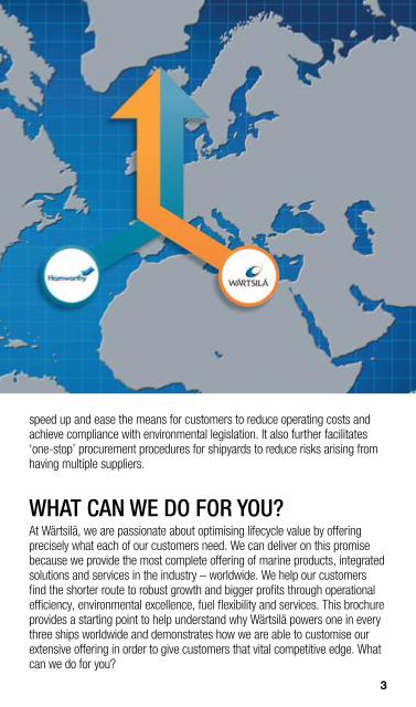
THE MOST COMPLETE OFFERING OF MARINE SOLUTIONS IN THE WORLD Wärtsilä’s acquisition of the British-headquartered, global engineering company Hamworthy plc became effective on 31st January 2012. This acquisition is a major step in Wärtsilä’s strategy to strengthen its position as a total solutions provider, and to be the most valued partner for its customers with a complete range of products, integrated solutions, and services to the marine and offshore industries.
Wärtsilä already has an exceptionally broad offering that covers the complete lifecycle of a vessel, from initial ship design to daily operating requirements, and which is backed by the most extensive global service network in the industry.
Hamworthy’s portfolio of high technology products and systems represents a valuable complementary addition to this range. With the marine and offshore industries undergoing challenging times as a result of economic and environmental restrictions, the combining of the two companies’ strengths will
2
YOUR SHORTERROUTE TOBIGGER PROFITSIS NOW EVENSHORTER
speed up and ease the means for customers to reduce operating costs and achieve compliance with environmental legislation. It also further facilitates ‘one-stop’ procurement procedures for shipyards to reduce risks arising from having multiple suppliers.
WHAT CAN WE DO FOR YOU? At Wärtsilä, we are passionate about optimising lifecycle value by offering precisely what each of our customers need. We can deliver on this promise because we provide the most complete offering of marine products, integrated solutions and services in the industry – worldwide. We help our customers find the shorter route to robust growth and bigger profits through operational efficiency, environmental excellence, fuel flexibility and services. This brochure provides a starting point to help understand why Wärtsilä powers one in every three ships worldwide and demonstrates how we are able to customise our extensive offering in order to give customers that vital competitive edge. What can we do for you?
3
TABLE OF CONTENTS
Fuel Flexibility & Gas Solutions 6
Ship Design Solutions 18
ENVIRONMENTAL SOLUTIONS 24
Emissions Reduction 26
High Efficiency Waste Heat Recovery 26 Scrubber Technology 27 NOX Reducer 32 Water Treatment 36
Ballast Water Management 36 Bilge Water Guard 39 Condensation Plants 39 Evaporators 40 Waste Water Treatment 41
MARINE PRODUCTS 44
Automation 46
Vessel Automation 46 Propulsion Controls 50 Power Electric Systems 51
Electric Propulsion Packages 51 Variable Speed Drives 52 Switchboards 54 Engines & Generating Sets 56
Low Speed Engines 56 Low Speed X-generation Engines 72 Medium Speed Engines 80 Dual Fuel Engines 89 Generating Sets 94 Auxiliary Systems 104 Gears 106
Single input gears 106 Twin input gears 110 Propulsors 112
Controllable Pitch Propellers 112 Fixed Pitch Propellers 116 Steerable Thrusters 120
4

Fuel Flexibility & Gas Solutions 6
Ship Design Solutions 18
ENVIRONMENTAL SOLUTIONS 24
Emissions Reduction 26
High Efficiency Waste Heat Recovery 26Scrubber Technology 27NOX Reducer 32Water Treatment 36
Ballast Water Management 36Bilge Water Guard 39Condensation Plants 39Evaporators 40Waste Water Treatment 41
MARINE PRODUCTS 44
Automation 46
Vessel Automation 46Propulsion Controls 50Power Electric Systems 51
Electric Propulsion Packages 51Variable Speed Drives 52Switchboards 54Engines & Generating Sets 56
Low Speed Engines 56Low Speed X-generation Engines 72Medium Speed Engines 80Dual Fuel Engines 89Generating Sets 94Auxiliary Systems 104Gears 106
Single input gears 106Twin input gears 110 Propulsors 112
Controllable Pitch Propellers 112Fixed Pitch Propellers 116Steerable Thrusters 120
Transverse Thrusters 126 Waterjets 128 Rudders 134 Seals, Bearings & Stern Tubes 136
Sealing Solutions 137 Bearing Solutions 141 Stern Tube Solutions 143 Other Seals and Bearings Products 143
FUEL FLEXIBILITY 146
Gas Systems 146
Gas Recovery 146 LNG Handling 150 LPG Systems 156 Pumps & Valves 158
Booster Pumps 158 Deepwell Pumps 159 Engine Room Pumps 163 Fi Fi Systems 164 Portable Pumps 165 Pump Room Systems 165 Valves 166 Compressors 168
High Pressure Air & Gas 168 Hydrocarbon Gas 171 Inert Gas 172
Flue Gas 172 Inert Gas Generators 172 Mult-Inert 174 Nitrogen Generation 175 Wärtsilä Propac Packages 176
Solutions Comparison Tools 178
SERVICES 180
Wärtsilä WORLDWIDE 184
5

FLEXIBILITY OF FUEL CHOICE Wärtsilä’s dual-fuel engines have exceeded 5 million running hours in both land-based and marine applications. This milestone represents a dualfuel technology track record that cannot be matched by any other engine manufacturer.
Wärtsilä, a global leader in complete lifecycle power solutions for the marine and energy markets, is the recognised frontrunner in dual-fuel engine technology. The Wärtsilä DF engine series is increasingly the power solution choice for utilities and energy companies, as well as for all segments of the marine industry, worldwide.
6

THE ONLY MARINE GAS SOLUTIONS WITH A LONG TRACK RECORD
Dual-fuel engine technology provides the flexibility to switch between the use of natural gas and heavy fuel oil (HFO), light fuel oil (LFO) and various other liquid fuels. This flexibility in fuel choice offers numerous tangible benefits, both economic and environmental. With oil prices fluctuating and environmental regulations becoming increasingly stringent, the operator has the freedom to select the most cost-effective and readily available fuel, whilst also having the ability to utilise natural gas in order to comply with emission limitations.
FUEL FLEXIBILITY
7
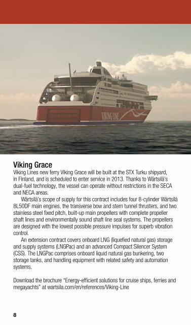
Viking Grace Viking Lines new ferry Viking Grace will be built at the STX Turku shipyard, in Finland, and is scheduled to enter service in 2013. Thanks to Wärtsilä’s dual-fuel technology, the vessel can operate without restrictions in the SECA and NECA areas.
Wärtsilä’s scope of supply for this contract includes four 8-cylinder Wärtsilä 8L50DF main engines, the transverse bow and stern tunnel thrusters, and two stainless steel fixed pitch, built-up main propellers with complete propeller shaft lines and environmentally sound shaft line seal systems. The propellers are designed with the lowest possible pressure impulses for superb vibration control.
An extension contract covers onboard LNG (liquefied natural gas) storage and supply systems (LNGPac) and an advanced Compact Silencer System (CSS). The LNGPac comprises onboard liquid natural gas bunkering, two storage tanks, and handling equipment with related safety and automation systems.
Download the brochure “Energy-efficient solutions for cruise ships, ferries and megayachts” at wartsila.com/en/references/Viking-Line
8
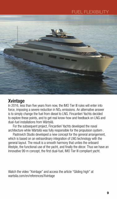
Xvintage In 2016, less than five years from now, the IMO Tier III rules will enter into force, imposing a severe reduction in NOX emissions. An alternative answer is to simply change the fuel from diesel to LNG. Fincantieri Yachts decided to explore these points, and to get real know-how and feedback on LNG and dual-fuel installations from Wärtsilä.
For the subsequent project, Fincantieri Yachts developed the naval architecture while Wärtsilä was fully responsible for the propulsion system .
Pastrovich Studio developed a new concept for the general arrangement, which is based on an extraordinary integration of LNG technology with the general layout. The result is a smooth harmony that unites the onboard lifestyle, the functional use of the yacht, and finally the décor. Thus we have an innovative 99 m concept, the first dual-fuel, IMO Tier III compliant yacht.
Watch the video “Xvintage” and access the article “Gliding high” at wartsila.com/en/references/Xvintage
FUEL FLEXIBILITY
9

Provalys When taken into service in 2006, the 154,000 m3 LNG carrier ‘Provalys’ was the largest LNG carrier in existence. The vessel is propelled by dual-fuel engines and electric propulsion. The solution offers LNG carriers a number of significant advantages, including lower overall fuel consumption, fuel flexibility, and reduced emissions.
The heart of the system is four dual-fuel engines; three 12-cylinder and one 6-cylinder Wärtsilä 50DF, giving a combined output of 39.9 MW.
The vessel is employed to carry liquefied natural gas (LNG) from Norway or Egypt. The propulsion solution for the ‘Provalys’ uses dual-fuel engines for electric power generation. The electric power is supplied to an electric propulsion system, as with the diesel-electric propulsion systems on modern cruise ships.
The ship is designed to be capable of responding to the alternative of trading on the spot market.
Download the brochures “Solutions for Merchant vessels” and “Shipping in the gas age” at wartsila.com/en/references/Provalys
10

FUEL FLEXIBILITY
Bit Viking The 25,000 dwt product tanker ‘Bit Viking’ was the first vessel ever to undergo a conversion by Wärtsilä from heavy fuel oil to liquefied natural gas (LNG) operation. In October 2011, the vessel was handed over to the customer, Tarbit Shipping.
The scope of the conversion package from Wärtsilä included deckmounted gas fuel systems, piping, two six-cylinder Wärtsilä 46 engines converted to Wärtsilä 50DF units with related control systems and all adjustments to the ship’s systems necessitated by the conversion.
The ‘Bit Viking’ utilises Wärtsilä’s new LNGPac system, which enables the safe and convenient onboard storage of LNG. The storage tanks provide the vessel with 12 days of autonomous operation at 80% load, with the option to switch to marine gas oil if an extended range is required. When visiting EU ports, which have a 0.1% limit on sulphur emissions, the vessel operates on gas.
Access the presentation “Bit Viking, first LNG conversion project in the world” at wartsila.com/en/references/Bit-Viking
11

Viking Lady Delivered in 2009, the ‘Viking Lady’ is not like any other offshore supply ship. The LNG-fuelled vessel, which is owned by Eidesvik Offshore, was the very first merchant ship to use a fuel cell as part of its propulsion system. The fuel cell, which generates an electric output of 330 kW, was installed in the autumn of 2009 and has successfully run for more than 18,500 hours. Based on this, the ‘Viking Lady’ is already one of the world’s most environmentally friendly ships.
The ship combines four Wärtsilä 32DF dual-fuel engines with advanced vessel automation and Wärtsilä’s innovative Low Loss Concept, which minimizes electrical losses. The vessel, a Wärtsilä Ship Design, runs on liquefied natural gas (LNG).
In March 2012, DNV announced that a true hybrid energy system is currently being developed for installation on board the offshore supply vessel ‘Viking Lady’.
Download the brochure “Offshore solutions, optimised performance” at wartsila.com/en/references/Viking-Lady
Photo: Eidesvik
12

Viking Prince The ‘Viking Prince’ entered service in March 2012. The environmental friendly LNG dual-fuel engines ensure low emissions of NOX and the reduction of CO2.
The vessel is a Wärtsilä VS 489 Gas PSV design and features outstanding energy efficiency, a unique hull form, fuel flexibility, and outstanding vessel performance in areas such as fuel economy and cargo capacity.
The Eidesvik orders include a unique configuration of the gas electric propulsion system. This is based on a combination comprising the Wärtsilä Low Loss Concept for Electric Propulsion, the Wärtsilä 34DF main engines, and the Wärtsilä 20DF engine.
Wärtsilä has the ability to offer total concept solutions that include the design of the vessel, the propulsion plant, electrics and automation, and a host of fuel saving and environmentally sustainable options.
Access the article “Leading ‘green’ offshore operator chooses Wärtsilä total solution” at wartsila.com/en/references/Viking-Prince
Photo: Harald Valderhaug
FUEL FLEXIBILITY
13
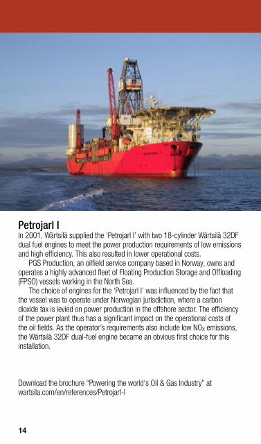
Petrojarl I In 2001, Wärtsilä supplied the ‘Petrojarl I’ with two 18-cylinder Wärtsilä 32DF dual fuel engines to meet the power production requirements of low emissions and high efficiency. This also resulted in lower operational costs.
PGS Production, an oilfield service company based in Norway, owns and operates a highly advanced fleet of Floating Production Storage and Offloading (FPSO) vessels working in the North Sea.
The choice of engines for the ‘Petrojarl I’ was influenced by the fact that the vessel was to operate under Norwegian jurisdiction, where a carbon dioxide tax is levied on power production in the offshore sector. The efficiency of the power plant thus has a significant impact on the operational costs of the oil fields. As the operator’s requirements also include low NOX emissions, the Wärtsilä 32DF dual-fuel engine became an obvious first choice for this installation.
Download the brochure “Powering the world‘s Oil & Gas Industry” at wartsila.com/en/references/Petrojarl-I
14

P-63 FPSO In May 2010, Wärtsilä signed a contract with the Brazilian industrial group QUIP to supply three main power modules for a new P-63 Floating Production Storage and Offloading vessel.
Designed and produced by Wärtsilä, each power module will include two 18-cylinder 50DF tri-fuel engines, as well as alternators and all required auxiliary equipment. The 323,000 dwt ultra-large crude carrier (ULCC), the ‘BW Nisa’, will be utilised for the P-63 project. Wärtsilä is supplying a 100 MW fuel-flexible topside power-module solution, engineered and fabricated by Wärtsilä. The EPC model mitigates completion risks of the project and allows QUIP to focus on the process modules. The gas-fired power solution is estimated to reduce the levels of carbon-dioxide emissions by as much as 93,000 tons per year, compared to conventional technologies.
Watch the video “Wärtsilä powering P-63 FPSO vessel” at wartsila.com/en/references/P-63
FUEL FLEXIBILITY
15
FUEL FLEXIBILITY AND GAS
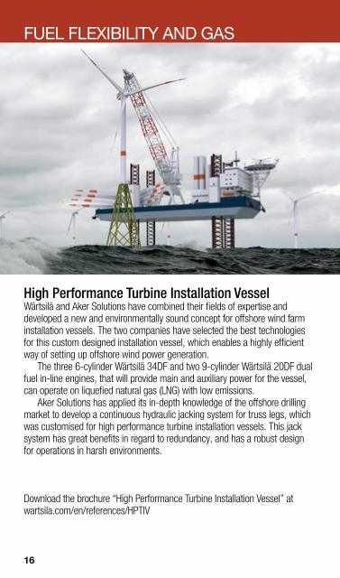
High Performance Turbine Installation Vessel Wärtsilä and Aker Solutions have combined their fields of expertise and developed a new and environmentally sound concept for offshore wind farm installation vessels. The two companies have selected the best technologies for this custom designed installation vessel, which enables a highly efficient way of setting up offshore wind power generation.
The three 6-cylinder Wärtsilä 34DF and two 9-cylinder Wärtsilä 20DF dual fuel in-line engines, that will provide main and auxiliary power for the vessel, can operate on liquefied natural gas (LNG) with low emissions.
Aker Solutions has applied its in-depth knowledge of the offshore drilling market to develop a continuous hydraulic jacking system for truss legs, which was customised for high performance turbine installation vessels. This jack system has great benefits in regard to redundancy, and has a robust design for operations in harsh environments.
Download the brochure “High Performance Turbine Installation Vessel” at wartsila.com/en/references/HPTIV
16
FUEL FLEXIBILITY
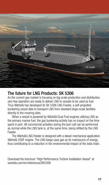
The future for LNG Products: SK 5306 As the current gas market is focusing on big scale production and distribution, very few operators are ready to deliver LNG to vessels to be used as fuel. Thus Wärtsilä has developed its SK 5306 LNG Feeder, a self-propelled bunkering vessel able to transport LNG from standard large-scale facilities directly to the mooring sites.
When a vessel is powered by Wärtsilä Dual-Fuel engines utilizing LNG as the primary marine fuel, the gas bunkering activity has no impact on the time spent in port. All commercial activities during the port call can be performed as normal while the LNG tank is, at the same time, being refilled by the LNG Feeder.
The Wärtsilä LNG Feeder is designed with a diesel-mechanical application Wärtsilä 20DF engine. The LNG barge uses gas as its mainsource of energy, thus contributing to a reduction in the environmental impact of the total chain.
Download the brochure “High Performance Turbine Installation Vessel” at wartsila.com/en/references/SK5306
17

PAST, PRESENT AND FUTURE SUCCESS
SHIP DESIGN PORTFOLIO & SERVICES With the benefit of 50 years of experience, Wärtsilä Ship Design is able to offer a complete range of options; from fully tailor-made unique designs, to standard, well proven, off-the-shelf designs.
A ship is built to last several decades, and decisions made in the early design stages will have consequences that effect the operation of the vessel throughout its entire lifetime. Wärtsilä takes operational considerations, as well as construction friendliness, into account during the design phase. Wärtsilä’s vision is to be its customers’ most valued business partner. We will support our customers in optimising their assets with the best designs, high quality products and system solutions, global services, as well as maintenance and operational assistance.
Wärtsilä primarily provides designs for merchant, offshore and special vessels. Offshore construction vessels, anchor handling vessels, platform supply vessels, cable layers, pipe layers, container vessels, chemical tankers, ice breakers, research vessels, and offshore wind farm installation vessels are amongst our most recent references.
18

SHIP DESIGN SOLUTIONS
We cover the full range of ship design disciplines, including naval architecture, hull optimisation, stability calculations, hull and structural engineering, accommodation and outfitting, machinery and piping engineering, as well as automation and electrical engineering.
Wärtsilä offers basic designs, including classification drawings, detail design, and optimised 3D production drawings for shipyards worldwide. Planning approval, design optimisation, and on-site newbuilding supervision are some of the consultancy services provided to shipyards and owners during the construction phase.
Wärtsilä also offers a comprehensive range of marine consultancy services for shipyards or ship owners who are involved in newbuilding, conversion, and retrofit projects.
Wärtsilä provides technical, operational and commercial feasibility studies, conceptual and initial designs, the preparation of general arrangements, and with all necessary related documents.
Wärtsilä assists its customers with tenders by preparing tendering documents and presentation material, and by participating in the evaluation processes.
Wärtsilä is passionate about optimising lifecycle
value by delivering whatever you need from the total
offering. Let´s work together to find
the right route for you.
19
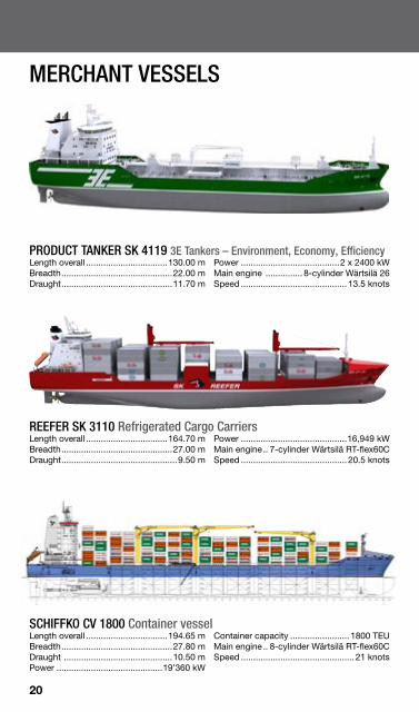
SCHIFFKO CV 1800 Container vessel Length overall .................................194.65 m Breadth.............................................27.80 m Draught ............................................10.50 m Power ...........................................19’360 kW
Container capacity ........................ 1800 TEU Main engine.. 8-cylinder Wärtsilä RT-flex60C Speed .............................................. 21 knots
PRODUCT TANKER SK 4119 3E Tankers – Environment, Economy, Efficiency Length overall .................................130.00 m Breadth.............................................22.00 m Draught.............................................11.70 m
Power ........................................2 x 2400 kW Main engine ............... 8-cylinder Wärtsilä 26 Speed ........................................... 13.5 knots
REEFER SK 3110 Refrigerated Cargo Carriers Length overall .................................164.70 m Breadth.............................................27.00 m Draught...............................................9.50 m
Power ...........................................16,949 kW Main engine.. 7-cylinder Wärtsilä RT-flex60C Speed ........................................... 20.5 knots
MERCHANT VESSELS
20
SHIP DESIGN SOLUTIONS
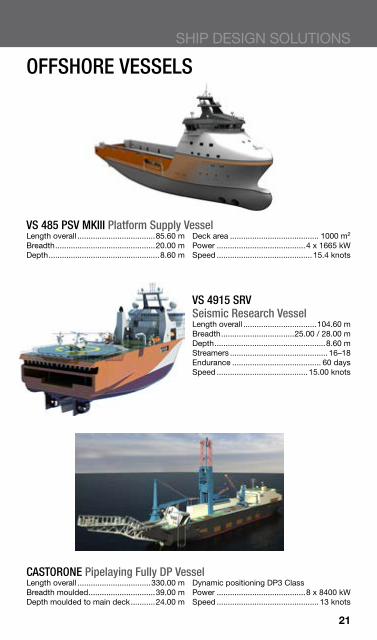
OFFSHORE VESSELS
VS 485 PSV MKIII Platform Supply Vessel Length overall ...................................85.60 m Breadth.............................................20.00 m Depth..................................................8.60 m
Deck area ........................................ 1000 m2
Power ........................................4 x 1665 kW Speed ........................................... 15.4 knots
CASTORONE Pipelaying Fully DP Vessel Length overall .................................330.00 m Breadth moulded..............................39.00 m Depth moulded to main deck...........24.00 m
Dynamic positioning DP3 Class Power ........................................8 x 8400 kW Speed .............................................. 13 knots
VS 4915 SRV Seismic Research Vessel Length overall .................................104.60 m Breadth.................................25.00 / 28.00 m Depth..................................................8.60 m Streamers ............................................ 16–18 Endurance ........................................ 60 days Speed ......................................... 15.00 knots
21

OFFSHORE VESSELS
VS 491 CD AHTS Anchor Handling vessel Length overall ...................................91.00 m Bollard pull............................................300 T Breadth .............................................22.00 m Power ........................................2 x 8000 kW Depth to 1st deck ...............................9.60 m Main engine ............. 16-cylinder Wärtsilä 32
VS 4004 MAS Multipurpose Accommodation Ship Length overall .................................112.80 m Draft designed ......................................5.5 m Breadth .............................................30.00 m Generators .................................4 x 3000 kW Depth .................................................9.00 m Accommodation ......................................400
Carousel .............................................2500 T Main engines: 8-cylinder Wärtsilä 32, 4 x 3800 kW 7-cylinder Wärtsilä 32, 2 x 3300 kW
VS 4616 PLV Pipe Layer Vessel Length over all ................................146.00 m Breadth .............................................30.00 m Depth ................................................12.70 m Crane ....................................................250 T Tensioners w 4 tracks x 2 (total) ...........550 T
22

SHIP DESIGN SOLUTIONS
PRV 120 Polar Research Vessel Length overall .................................129.00 m Breadth moulded..............................29.80 m Depth moulded to main deck...........12.05 m
Endurance ..................20,000 nm or 60 days Power (diesel-electric) ...................23.1 MWe Speed .......................................12 / 15 knots
VS 6208 TR Trawler/Purse Seiner Length overall ...................................86.30 m Breadth.............................................17.60 m Depth................................................10.20 m
RSW capacity.................................. 3284 m3
Power ........................................1 x 5220 kW Speed ......................................... 17.00 knots
CWA 92 m Self-unloading Barge Length overall ...................................92.40 m Breadth.............................................28.00 m Depth..................................................6.50 m
Deadweight ........................................1500 T Transfer hopper ..............................2 x 70 m3
Articulated boom conveyor ...........2000 mt/h
SPECIAL VESSELS
23

ENVIRONMENTAL TECHNOLOGIES Environmental legislation impacting the global shipping industry continues to increase. In response to this, Wärtsilä is developing technologies to strategically meet these new requirements. We have made a long-term commitment to facilitating environmentally sound operations in terms of low emissions, low environmental impact and true sustainability. As this range of new technologies continue to come on line, they will be offered to our customers as standard on newbuilds, and will also be available when retrofitting existing vessels.
THIS IS THE WORLD OF SHIPPING WITHOUT
24

ENVIRONMENTAL SOLUTIONS
Our ever-expanding portfolio of environmental products and services is geared towards meeting the full spectrum of environmental challenges. Wärtsilä Marine has placed particular emphasis on optimising lifecycle efficiency, minimising environmental impact by reducing air and water emissions, and minimising waste volumes.
Read Wärtsilä’s approach to sustainability at http://wartsila.com/en/sustainability/Environmentalresponsibility/Overview
25

M
G
G
G
G
G
Exhaust turbine
Aux. engines
Ship service power
Ship service steam Exhaust gas economizer
Main engine
Steam turbine
Turobchargers Motor/generator
Schematic of a High-Efficiency Waste Heat Recovery plant typical for large container ships.
HIGH-EFFICIENCY WASTE HEAT RECOVERY (WHR) Waste heat recovery is an effective technology for simultaneously cutting exhaust gas emissions and reducing fuel consumption. High-Efficiency Waste Heat Recovery plants can be installed with Wärtsilä engines. This enables up to 12% of the main engine shaft power to be recovered as electrical power for use as additional ship propulsion power and for shipboard services. These WHR plants thus cut exhaust gas emissions and deliver fuel savings of up to 12%.
Steam based WHR has already been successfully fitted in several installations to Wärtsilä RT-flex low-speed marine engines. In the WHR plant, a turbo-generator combines input from a steam turbine and an exhaust gas power turbine to generate electrical power while steam from the economiser is available for ship service heating. Steam based WHR is recommended for vessels with high installed power.
26

ENVIRONMENTAL SOLUTIONS
SCRUBBERS FOR ALL SHIP TYPES Due to existing regulations on emissions to air from the International Maritime Organization (IMO), and with the European Union working towards an alignment with IMO MARPOL Annex VI, the marine industry will need to choose path on how to achieve compliance.
With one of Wärtsilä SOX Exhaust Gas Cleaning Systems installed, you will comply with all existing and proposed regulations from IMO and the EU. Wärtsilä scrubbers are designed to provide flexibility and reliable operations wherever you operate. The systems are suitable for both new buildings and retrofitting of existing vessels having either 2-stroke or 4-stroke engines as well as oil-fired boilers. We can also provide complete ship design and a variety of pump systems.
Having the largest installed base of any marine scrubber supplier and a dedicated test laboratory, has enabled Wärtsilä to optimise their products to be reliable, easy to operate and easy to install.
WÄRTSILÄ HYBRID SCRUBBER SYSTEM In addition to closed and open loop systems, Wärtsilä provides hybrid solutions. These solutions have the flexibility to operate in both open and closed loop.
The hybrid approach enables operation in closed loop mode when required, for instance whilst in port and during maneuvering using NaOH as a buffer. When at sea the switch can be made to open loop using only seawater.
27
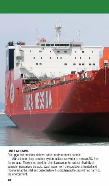
LINEA MESSINA Our upgraded scrubber delivers added environmental benefits
Wärtsilä open loop scrubber system utilises seawater to remove SOX from the exhaust. There is no need for chemicals since the natural alkalinity of seawater neutralizes the acid. Wash water from the scrubber is treated and monitored at the inlet and outlet before it is discharged to sea with no harm to the environment.
28
ENVIRONMENTAL SOLUTIONS
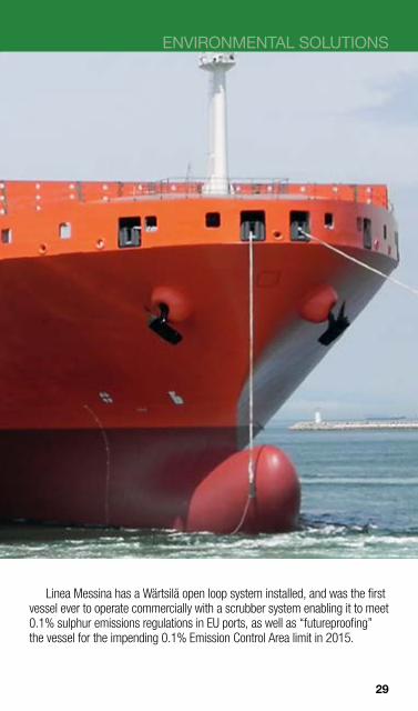
Linea Messina has a Wärtsilä open loop system installed, and was the first vessel ever to operate commercially with a scrubber system enabling it to meet 0.1% sulphur emissions regulations in EU ports, as well as “futureproofing” the vessel for the impending 0.1% Emission Control Area limit in 2015.
29

WÄRTSILÄ CLOSED LOOP SCRUBBER SYSTEM Following the Hamworthy acquisition by Wärtsilä: Wärtsilä Fresh Water Scrubber becomes Wärtsilä Closed Loop Scrubber
Wärtsilä Closed Loop Scrubber operates in a closed loop, i.e. the wash water is being circulated within the scrubber. Exhaust gas enters the scrubber and is sprayed with water that has been mixed with caustic soda (NaOH). The sulphur oxides in the exhaust react with this mixture and are thereby neutralized. A small bleed-off is extracted from the closed loop and treated to fulfil requirements stipulated by IMO. Cleaned effluents can safely be discharged overboard with no harm to the environment. If operation in zero discharge mode is requested, the effluent can be led to a holding tank for scheduled and periodical discharge.
ØD
Øout
H C
U
E
Øin
ØP
B
30

ENVIRONMENTAL SOLUTIONS
SCRUBBER UNIT DIMENSIONS Scrubber
type Capacity
(kg/s) ØD
(mm) ØP
(mm) Øin
(mm) Øout (mm)
H (mm)
C (mm)
B (mm)
E (mm)
Weight dry (kg)
Weight wet (kg)
WM 92 1.46 920 378 365 385 4 400 3 113 459 765 1 100 1 300
WM 98 1.66 980 402 385 400 4 500 3 133 483 785 1 200 1 400
WM 104 1.88 1 040 427 410 430 4 600 3 159 506 810 1 300 1 500
WM 111 2.14 1 110 456 440 460 4 700 3 190 533 840 1 400 1 600
WM 118 2.43 1 180 484 465 485 4 800 3 215 561 865 1 500 1 800
WM 125 2.73 1 250 513 495 520 4 900 3 246 588 895 1 600 1 900
WM 133 3.10 1 330 546 525 550 5 000 3 276 619 925 1 800 2 000
WM 141 3.49 1 410 579 560 585 5 100 3 312 650 960 1 900 2 300
WM 149 3.90 1 490 611 590 620 5 200 3 343 682 990 2 000 2 400
WM 158 4.40 1 580 648 625 655 5 300 3 378 717 1 025 2 200 2 600
WM 167 4.93 1 670 685 660 700 5 400 3 414 752 1 060 2 400 2 800
WM 177 5.55 1 770 726 700 735 5 500 3 455 791 1 100 2 600 3 100
WM 187 6.20 1 870 767 740 775 5 700 3 496 830 1 140 2 800 3 400
WM 198 6.97 1 980 812 785 820 5 900 3 542 873 1 185 3 100 3 700
WM 209 7.78 2 090 857 830 870 6 000 3 588 916 1 230 3 400 4 100
WM 221 8.72 2 210 907 875 915 6 200 3 633 962 1 275 3 700 4 500
WM 233 9.72 2 330 956 925 970 6 400 3 684 1 009 1 325 4 000 4 900
WM 246 10.85 2 460 1 009 975 1 020 6 500 3 735 1 060 1 375 4 300 5 300
WM 259 12.06 2 590 1 062 1025 1 070 6 700 3 786 1 111 1 425 4 700 5 800
WM 273 13.42 2 730 1 120 1080 1 135 6 900 3 843 1 165 1 480 5 100 6 300
WM 287 14.87 2 870 1 177 1140 1 190 7 100 3 904 1 220 1 540 5 500 6 900
WM 302 16.50 3 020 1 239 1195 1 255 7 300 3 960 1 278 1 595 6 000 7 500
WM 317 18.21 3 170 1 300 1255 1 315 7 500 4 021 1 337 1 655 6 500 8 200
WM 333 20.14 3 330 1 366 1320 1 380 7 700 4 088 1 399 1 720 7 100 8 900
WM 350 22.30 3 500 1 435 1385 1 455 7 900 4 154 1 465 1 785 7 700 9 700
WM 367 24.57 3 670 1 505 1 450 1 525 8 200 4 220 1 532 1 850 8 300 10 600
WM 385 27.09 3 850 1 579 1600 1 525 8 400 4 297 1 602 1 925 9 000 11 500
WM 403 29.75 4 030 1 653 1595 1 670 8 700 4 368 1 672 1 995 9 800 12 500
WM 422 32.69 4 220 1 731 1675 1 755 8 900 4 450 1 746 2 075 10 600 13 500
WM 442 35.93 4 420 1 813 1750 1 835 9 200 4 526 1 824 2 150 11 500 14 700
WM 462 39.34 4 620 1 895 1830 1 920 9 500 4 608 1 902 2 230 12 400 15 900
WM 483 43.09 4 830 1 981 1910 2 005 9 700 4 690 1 984 2 310 13 400 17 300
WM 505 47.20 5 050 2 071 2010 2 100 10 000 4 792 2 070 2 410 14 500 18 700
WM 527 51.51 5 270 2 161 2085 2 190 10 300 4 868 2 156 2 485 15 700 20 200
WM 550 56.22 5 500 2 255 2175 2 285 10 600 4 960 2 245 2 575 16 900 21 900
WM 574 61.36 5 740 2 354 2275 2 385 11 000 5 062 2 339 2 675 18 300 23 700
WM 599 66.96 5 990 2 456 2370 2 490 11 300 5 159 2 437 2 770 19 700 25 600
WM 624 72.81 6 240 2 559 2470 2 590 11 600 5 261 2 534 2 870 21 200 27 700
WM 650 79.17 6 500 2 665 2575 2 700 12 000 5 368 2 635 2 975 22 900 29 800
WM 677 86.06 6 770 2 776 2680 2 810 12 400 5 475 2 741 3 080 24 600 32 200
WM 705 93.51 7 050 2 891 2790 2 930 12 700 5 588 2 850 3 190 26 500 34 700
WM 733 101.29 7 330 3 006 2900 3 045 13 100 5 700 2 959 3 300 28 500 37 400
WM 762 109.69 7 620 3 125 3015 3 165 13 500 5 817 3 072 3 415 30 600 40 200
WM 792 118.74 7 920 3 248 3135 3 290 13 900 5 940 3 189 3 535 32 900 43 200
WM 822 128.16 8 220 3 371 3255 3 415 14 300 6 062 3 306 3 655 35 200 46 400
WM 853 138.29 8 530 3 498 3375 3 540 14 800 6 185 3 427 3 775 37 800 49 800
WM 885 149.16 8 850 3 629 3500 3 675 15 200 6 312 3 552 3 900 40 400 53 400
WM 918 160.82 9 180 3 764 3635 3 810 15 600 6 450 3 681 4 035 43 300 57 200
WM 951 172.93 9 510 3 900 3765 3 950 16 100 6 583 3 809 4 165 46 300 61 200
WM 985 185.89 9 850 4 036 3900 4 090 16 500 6 720 3 942 4 300 49 400 65 400
31

WÄRTSILÄ CLOSED LOOP SCRUBBER SYSTEM
Scrubber type
Capacity (kg/s)
Specific exhaust gas flow (kg/kWh)
6 6.5 7 7.5 8 8.5 9 9.5
Diesel engine power (kW)
WM 92 1.46 876 809 751 701 657 618 584 553 WM 98 1.66 996 919 854 797 747 703 664 629
WM 104 1.88 1 128 1 041 967 902 846 796 752 712 WM 111 2.14 1 284 1 185 1 101 1 027 963 906 856 811 WM 118 2.43 1 458 1 346 1 250 1 166 1 094 1 029 972 921 WM 125 2.73 1 638 1 512 1 404 1 310 1 229 1 156 1 092 1 035 WM 133 3.10 1 860 1 717 1 594 1 488 1 395 1 313 1 240 1 175 WM 141 3.49 2 094 1 933 1 795 1 675 1 571 1 478 1 396 1 323 WM 149 3.90 2 340 2 160 2 006 1 872 1 755 1 652 1 560 1 478 WM 158 4.40 2 640 2 437 2 263 2 112 1 980 1 864 1 760 1 667 WM 167 4.93 2 958 2 730 2 535 2 366 2 219 2 088 1 972 1 868 WM 177 5.55 3 330 3 074 2 854 2 664 2 498 2 351 2 220 2 103 WM 187 6.20 3 720 3 434 3 189 2 976 2 790 2 626 2 480 2 349 WM 198 6.97 4 182 3 860 3 585 3 346 3 137 2 952 2 788 2 641 WM 209 7.78 4 668 4 309 4 001 3 734 3 501 3 295 3 112 2 948 WM 221 8.72 5 232 4 830 4 485 4 186 3 924 3 693 3 488 3 304 WM 233 9.72 5 832 5 383 4 999 4 666 4 374 4 117 3 888 3 683 WM 246 10.85 6 510 6 009 5 580 5 208 4 883 4 595 4 340 4 112 WM 259 12.06 7 236 6 679 6 202 5 789 5 427 5 108 4 824 4 570 WM 273 13.42 8 052 7 433 6 902 6 442 6 039 5 684 5 368 5 085 WM 287 14.87 8 922 8 236 7 647 7 138 6 692 6 298 5 948 5 635 WM 302 16.50 9 900 9 138 8 486 7 920 7 425 6 988 6 600 6 253 WM 317 18.21 10 926 10 086 9 365 8 741 8 195 7 712 7 284 6 901 WM 333 20.14 12 084 11 154 10 358 9 667 9 063 8 530 8 056 7 632 WM 350 22.30 13 380 12 351 11 469 10 704 10 035 9 445 8 920 8 451 WM 367 24.57 14 742 13 608 12 636 11 794 11 057 10 406 9 828 9 311 WM 385 27.09 16 254 15 004 13 932 13 003 12 191 11 473 10 836 10 266 WM 403 29.75 17 850 16 477 15 300 14 280 13 388 12 600 11 900 11 274 WM 422 32.69 19 614 18 105 16 812 15 691 14 711 13 845 13 076 12 388 WM 442 35.93 21 558 19 900 18 478 17 246 16 169 15 217 14 372 13 616 WM 462 39.34 23 604 21 788 20 232 18 883 17 703 16 662 15 736 14 908 WM 483 43.09 25 854 23 865 22 161 20 683 19 391 18 250 17 236 16 329 WM 505 47.20 28 320 26 142 24 274 22 656 21 240 19 991 18 880 17 886 WM 527 51.51 30 906 28 529 26 491 24 725 23 180 21 816 20 604 19 520 WM 550 56.22 33 732 31 137 28 913 26 986 25 299 23 811 22 488 21 304 WM 574 61.36 36 816 33 984 31 557 29 453 27 612 25 988 24 544 23 252 WM 599 66.96 40 176 37 086 34 437 32 141 30 132 28 360 26 784 25 374 WM 624 72.81 43 686 40 326 37 445 34 949 32 765 30 837 29 124 27 591 WM 650 79.17 47 502 43 848 40 716 38 002 35 627 33 531 31 668 30 001 WM 677 86.06 51 636 47 664 44 259 41 309 38 727 36 449 34 424 32 612 WM 705 93.51 56 106 51 790 48 091 44 885 42 080 39 604 37 404 35 435 WM 733 101.29 60 774 56 099 52 092 48 619 45 581 42 899 40 516 38 384 WM 762 109.69 65 814 60 751 56 412 52 651 49 361 46 457 43 876 41 567 WM 792 118.74 71 244 65 764 61 066 56 995 53 433 50 290 47 496 44 996 WM 822 128.16 76 896 70 981 65 911 61 517 57 672 54 280 51 264 48 566 WM 853 138.29 82 974 76 591 71 121 66 379 62 231 58 570 55 316 52 405 WM 885 149.16 89 496 82 612 76 711 71 597 67 122 63 174 59 664 56 524 WM 918 160.82 96 492 89 070 82 707 77 194 72 369 68 112 64 328 60 942 WM 951 172.93 103 758 95 777 88 935 83 006 77 819 73 241 69 172 65 531 WM 985 185.89 111 534 102 954 95 601 89 227 83 651 78 730 74 356 70 443
32

ENVIRONMENTAL SOLUTIONS
WÄRTSILÄ OPEN LOOP SCRUBBER SYSTEM Wärtsilä Open Loop Scrubber system operates in an open loop, utilising seawater to remove SOX from the exhaust. Exhaust gas enters the scrubber and is sprayed with water in three different stages. The sulphur oxide in the exhaust reacts with water and forms sulphuric acid. There is no need for chemicals since the natural alkalinity of seawater neutralizes the acid. Wash water from the scrubber is treated and monitored at the inlet and outlet, to make sure it is in line with the discharge criteria of MEPC 184(59), before it is discharged to sea with no harm to the environment. Linea Messina has a Wärtsilä Open Loop Scrubber system installed, and was the first vessel ever to operate commercially with a scrubber system, enabling it to meet 0.1% sulphur emissions regulations in EU ports, as well as “future proofing” the vessel for the impending 0.1% Emission Control Area limit in 2015.
33

EMISSION REDUCTION
Wärtsilä NOX Reducer (NOR).
WÄRTSILÄ NOX REDUCER (NOR) Wärtsilä has developed a NOX Reducer (NOR) based on selective, catalytic reduction technologies. The programme covers Wärtsilä’s medium-speed engine portfolio. The reduction in NOX emissions is 85–95%.
The size of the NOR is optimised in terms of performance and costs. The main components of the SCR installation are the reactor, which is the
core of the installation, a reagent pumping unit, a dosing unit for controlling the reagent fl ow, and an injection unit for feeding the reagent into the duct. The dosing unit is provided with a dedicated control cabinet. An emission monitoring system is available as option.
W
L
H
34

ENVIRONMENTAL SOLUTIONS
WÄRTSILÄ NOX REDUCER OVERALL DIMENSION TABLE
Engine power output
kW Reactor
size Reactor W
mm Reactor H
mm Reactor L
mm
Reactor weight
(including catalyst
elements) kg
Mixing duct total length (includes straight length)*
mm
<400 1
401–550 2 840 1000 3000 1200 3200
551–700 3
701–900 4 1000 1160 3116 1600 3600
901–1100 5
1101–1350 6 1160 1320 3230 2100 3900
1351–1600 7
1601–1850 8 1320 1480 3346 2600 4200
1851–2150 9
2151–2450 10 1480 1640 3460 3100 4500
2451–2800 11
2801–3150 12 1640 1800 3578 3600 4000
3151–3600 13
3601–4000 14 1800 1960 3692 4200 4200
4001–4400 15
4401–4800 16 1960 2120 3808 4800 4300
4801–5300 17
5301–5850 18 2120 2280 3924 5400 4400
5851–6300 19
6301–6800 20 2280 2440 4040 6000 4600
6801–7400 21
7401–8000 22 2440 2600 4156 6800 4700
8001–8600 23
8601–9200 24 2600 2760 4270 7500 4800
9201–9900 25
9901–10600 26 2760 2920 4420 8500 4900
10601–11200 27
11201–11900 28 2920 3080 4688 9600 4600
11901–12700 29
12701–13400 30 3080 3240 4716 10700 5100
13401–14200 31
14201–15000 32 3240 3400 4866 11900 5100
15001–15800 33
15801–16600 34 3400 3560 5014 13000 4900
16601–17500 35
17501–18400 36 3560 3720 5162 14300 5300
18401–19300 37
840
1000
1160
1320
1480
1640
1800
1960
2120
2280
2440
2600
2760
2920
3080
3240
3400
3560
3720
840
1000
1160
1320
1480
1640
1800
1960
2120
2280
2440
2600
2760
2920
3080
3240
3400
3560
3720
3000
3116
3230
3346
3460
3578
3692
3808
3924
4040
4156
4270
4420
4688
4716
4866
5014
5162
5412
1100 3000
1500 3400
2000 3800
2500 3900
3000 4100
3500 4300
4100 4400
4700 4000
5300 4100
5900 4300
6600 4400
7300 4500
8300 4600
9400 4700
10500 4800
11700 4900
12800 5400
14000 5100
17300 5500
19301–20200 38 3720 3880 5412 17500 5700
20201–21200 39 3880 3880 5560 20600 5900
21201–22200 40 3880 4040 5560 20900 6200
*The length of the mixing duct is case dependant. The figures are indicative.
35

BALLAST WATER MANAGEMENT SOLUTIONS FOR ALL SHIP TYPES In recognising that no one solution will be suitable across all ship types Wärtsilä is uniquely placed to offer owners & operators a choice of ballast water management solutions
WÄRTSILÄ AQUARIUS® EC The Wärtsilä AQUARIUS® EC ballast water management system (BWMS) provides robust technology for the treatment of ballast water using in-situ electro chlorination, across the full range of ship operating and environmental conditions.
The Wärtsilä AQUARIUS® EC BWMS is a simple and efficient two stage process involving filtration and electro-chlorination (EC). During uptake, seawater is first passed through a 40 micron back washing screen filter to remove particulate, sediment, zooplankton and phytoplankton. Disinfection of the filtered sea water is then carried out using hypochlorite generated from the side stream EC process, and controlled by the BWMS control system.
Upon discharge, the ballast water bypasses the filter and any residual active substance is neutralised using sodium bisulphite, to ensure that the ballast water is safe to discharge back to the sea in full compliance with MARPOL requirements.
By virtue of its modular design, the system’s inherent flexibility allows application across the full range of ship types and sizes, for both the new build and retrofit markets. Wärtsilä offers customers a range of flexible supply options, from the BWMS equipment only, to a full ‘turnkey’ service covering
36
ENVIRONMENTAL SOLUTIONS
all phases, from the initial review and ship survey, through to the supply, installation, and commissioning of the hardware, and continuing with lifecycle after sales service and support.
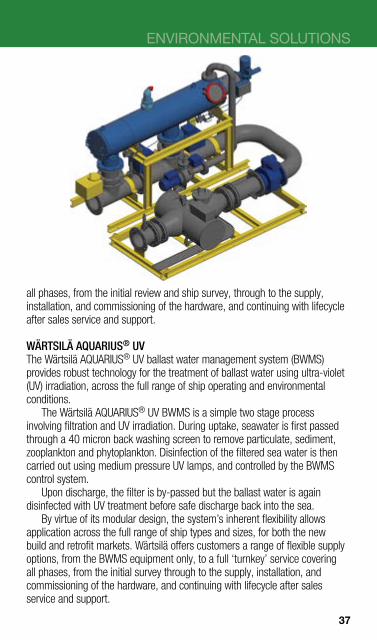
WÄRTSILÄ AQUARIUS® UV The Wärtsilä AQUARIUS® UV ballast water management system (BWMS) provides robust technology for the treatment of ballast water using ultra-violet (UV) irradiation, across the full range of ship operating and environmental conditions.
The Wärtsilä AQUARIUS® UV BWMS is a simple two stage process involving filtration and UV irradiation. During uptake, seawater is first passed through a 40 micron back washing screen to remove particulate, sediment, zooplankton and phytoplankton. Disinfection of the filtered sea water is then carried out using medium pressure UV lamps, and controlled by the BWMS control system.
Upon discharge, the filter is by-passed but the ballast water is again disinfected with UV treatment before safe discharge back into the sea.
By virtue of its modular design, the system’s inherent flexibility allows application across the full range of ship types and sizes, for both the new build and retrofit markets. Wärtsilä offers customers a range of flexible supply options, from the BWMS equipment only, to a full ‘turnkey’ service covering all phases, from the initial survey through to the supply, installation, and commissioning of the hardware, and continuing with lifecycle after sales service and support.
37

WATER TREATMENT
WÄRTSILÄ MARINEX UV The Wärtsilä Marinex UV ballast water management system (BWMS) provides unique technology for the treatment of ballast water using filtration and ultraviolet (UV) irradiation in one integrated housing.
The Wärtsilä Marinex UV BWMS is an integrated two stage process involving filtration and UV irradiation. During uptake, seawater enters the integrated unit and first passes through a self cleaning candle type filter to remove particulate, sediment, zooplankton and phytoplankton. Disinfection of the filtered sea water is then carried out using low pressure UV lamps, and controlled by the BWMS control system.
Upon discharge, the filter is by-passed but the ballast water is again disinfected with UV treatment before safe discharge back into the sea.
By virtue of its integrated design, the system’s inherent flexibility allows application across the full range of ship types and sizes, for both the new build and retrofit markets. Wärtsilä offers customers a range of flexible supply options, from the BWMS equipment only, to a full ‘turnkey’ service covering all phases, from the initial survey through to the supply, installation, and commissioning of the hardware, and continuing with lifecycle after sales service and support.
38
ENVIRONMENTAL SOLUTIONS
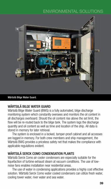
Wärtsilä Bilge Water Guard.
WÄRTSILÄ BILGE WATER GUARD Wärtsilä Bilge Water Guard (BWG) is a fully automated, bilge discharge monitoring system which constantly oversees and monitors the oil content in all discharges overboard. Should the oil content rise above the set limit, the flow will be re-routed back to the bilge tank. The system logs the discharge quantity and oil content as well as time and location of the ship. All data is stored in memory for later retrieval.
The system is enclosed in a locked, tamper-proof cabinet and all accesses are logged in memory. For both crew members and ship management, the Wärtsilä BWG provides a priceless safety net that makes the compliance with applicable regulations evident.
WÄRTSILÄ SERCK COMO CONDENSATION PLANTS Wärtsilä Serck Como air cooler condensers are especially suitable for the liquefaction of turbine exhaust steam at vacuum conditions. The use of lownoise fans enables installation near residential areas.
The use of water in condensing applications provides a highly cost effective solution. Wärtsilä Serck Como water cooled condensers can utilize fresh water, cooling tower water, river water and sea water.
39

WÄRTSILÄ SERCK COMO EVAPORATORS Wärtsilä Serck Como Multi-Stage Flash Evaporators offer extremely reliable thermal seawater desalination and are designed to produce fresh water, well water or industrial water. A particular advantage of our technology is that the specific heat consumption (or thermal efficiency) can be continuously adapted to the individual requirements of each vessel. The multi-stage flash technology is the only evaporation principle where heat transfer and evaporation are strictly separated.
Each Wärtsilä Serck Como Multiple Effect Evaporator is individually designed to the customer’s specific requirements.
Wärtsilä Serck Como Plate Type Evaporators employ a simple but effective process that utilizes the waste heat from the main diesel engine jacket water. Other media, such as steam or thermal oil, may also be used. We also offer various evaporation processes and evaporator designs.
Wärtsilä Serck Como Rising Films Evaporators enable the sea water to flow through the tubes of the vertical tube whilst the heating medium (steam or engine jacket water) flows around the tubes. The vapour produced inside the tubes flows upwards into the upper casing of the unit. Evaporation takes place under vacuum at low temperature.
Wärtsilä Serck Como land based evaporators are used for both ships and land-based installations for producing process and potable water. They are also used to reduce industrial waste water volumes.
40

Wärtsilä OWS oily water treatment unit. Wärtsilä OWS oily water treatment unit.
ENVIRONMENTAL SOLUTIONS
WÄRTSILÄ OILY WATER SEPARATOR The Wärtsilä oily water separator (OWS) gives the operator effective control over all bilge and sludge media as well as over any discharges made into the sea. The technology behind the Wärtsilä OWS is a combination of optimised traditional methods and innovative new solutions.
The separator consists of a four-stage, emulsion-breaking unit, in which each stage handles one key component of the sludge and bilge mix. It can handle input flows with an oil content of between 0 and 100%, making it the most versatile separator on the market.
All Wärtsilä units have successfully passed USCG / IMO type approval in accordance with 46 CFR §162.050 and MEPC.107(49). The amount of oil in water after treatment is guaranteed to be less than 5 ppm.
Technical data OWS 500 OWS 1000 OWS 2500
Capacity, max, m3/day 12 24 60
Length, mm 1185 2344 3210
Width, mm 765 1100 1400
Height, mm 1715 1855 1855
Weight, dry, kg 510 650 950
Weight, wet, kg 775 1950 2700
Power, kW 10 10 10
41

WÄRTSILÄ HAMWORTHY MEMBRANE BIOREACTOR (MBR) SYSTEMS Wärtsilä Hamworthy’s innovative MBR system is an evolution of the company’s proven sewage treatment technology for handling grey and black water waste. The technology is an advanced wastewater treatment process based on biological degradation and membrane separation. It delivers the highest quality discharge without requiring any addition or generation of chemicals hazardous to the maritime or shipboard environment.
WÄRTSILÄ HAMWORTHY miniMBR SYSTEMS Wärtsilä Hamworthy miniMBR systems are smaller, more compact versions of the company’s innovative MBR technology for handling grey and black water waste. By building on our successful experiences and working closely with our customers, we have been able to optimise the miniMBR system to produce an effective compact package. It is ideal for use on smaller cruise and naval vessels, plus ferries with up to a 200 complement, as well as FPSOs and accommodation platforms.
42

ENVIRONMENTAL SOLUTIONS
WÄRTSILÄ HAMWORTHY SEWAGE TREATMENT PLANTS Wärtsilä Hamworthy’s market-leading sewage treatment plants offer easyto-install, trouble-free systems for some of the harshest environments on the planet.
Optimised for the treatment of black and grey wastewater flows, and suitable for conventional gravity and vacuum fed collection systems, all plants in our STA-C and ST-C range are controlled automatically. This allows unattended operation, with reduced maintenance requirements and lower long-term operating costs. The systems are compact and modular in design, suitable for between-deck installations, and are adaptable to customer new build specifications. The STA-C and ST-C series sewage treatment plants are certified to meet IMO MEPC 159(55) guidelines, and are recognised by leading shipbuilders.
WÄRTSILÄ HAMWORTHY VACUUM TOILETS Wärtsilä Hamworthy vacuum toilets use air to drive waste from the toilet to the treatment tank or intermediate collection tank. This contemporarily styled toilet has a built-in vacuum breaker and flush memory, is simple to install, and is supplied ready to connect. The control mechanism can be accessed without removing the bowl. By using only approximately 1 litre of water, the amount of wastewater is dramatically reduced.
43

THE MOST COMPLETE OFFERING OF PRODUCTS, SOLUTIONS AND SERVICES IN THE MARINE INDUSTRY Wärtsilä enhances the business of its customers by providing products, solutions and services for the marine industry that are environmentally sustainable and economically sound. Being a technology leader and through the experience, know-how and dedication of our personnel, we are able to customise solutions according to specific customers’ needs for the benefit of our clients around the world.
YOUR SHORTER ROUTE TO BIGGER PROFITS
44

MARINE PRODUCTS
Wärtsilä has paved the way to improved performance and greater reliability for gas engines. As with many successful innovations, various strands of different technologies have been combined to produce a new and viable solution. The outcome of all this dual-fuel development work is unprecedented flexibility, both in fuel choice and operational performance. Since natural gas has low levels of harmful emissions, and is relatively low in price, such flexibility is increasingly seen as being the key to compliance with environmental legislation and to controlling escalating operational costs. Flexibility allows the most cost-effective and most readily available fuel to be used where possible, and gas to be used when feasible and where environmental regulations restrict the use of conventional liquid fuels.
45
AUTOMATION
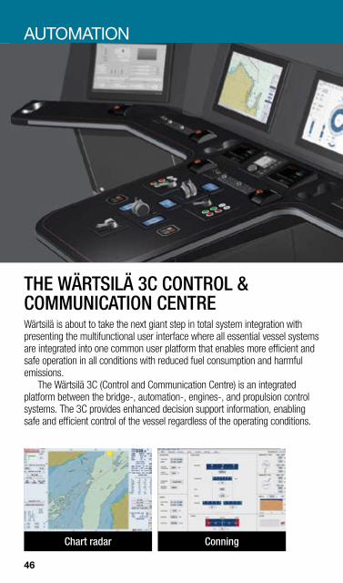
THE WÄRTSILÄ 3C CONTROL & COMMUNICATION CENTRE Wärtsilä is about to take the next giant step in total system integration with presenting the multifunctional user interface where all essential vessel systems are integrated into one common user platform that enables more efficient and safe operation in all conditions with reduced fuel consumption and harmful emissions.
The Wärtsilä 3C (Control and Communication Centre) is an integrated platform between the bridge-, automation-, engines-, and propulsion control systems. The 3C provides enhanced decision support information, enabling safe and efficient control of the vessel regardless of the operating conditions.
Chart radar Conning
46
MARINE PRODUCTS
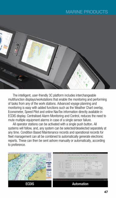
The intelligent, user-friendly 3C platform includes interchangeable multifunction displays/workstations that enable the monitoring and performing of tasks from any of the work stations. Advanced voyage planning and monitoring is easy with added functions such as the Weather Chart overlay, Econometer, Speed Pilot and online NavTex information directly available in ECDIS display. Centralised Alarm Monitoring and Control, reduces the need to mute multiple equipment alarms in case of a single sensor failure.
All operator stations can be activated with a single push button. All systems will follow, and, any system can be selected/deselected separately at any time. Condition Based Maintenance records and operational records for fleet management can all be combined to automatically generate electronic reports. These can then be sent ashore manually or automatically, according to preference.
ECDIS Automation
47
AUTOMATION
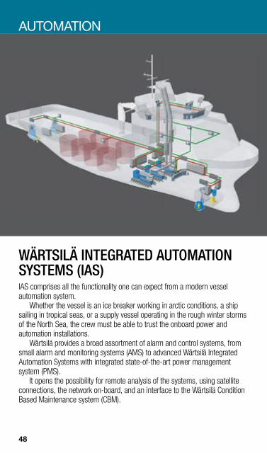
WÄRTSILÄ INTEGRATED AUTOMATION SYSTEMS (IAS) IAS comprises all the functionality one can expect from a modern vessel automation system.
Whether the vessel is an ice breaker working in arctic conditions, a ship sailing in tropical seas, or a supply vessel operating in the rough winter storms of the North Sea, the crew must be able to trust the onboard power and automation installations.
Wärtsilä provides a broad assortment of alarm and control systems, from small alarm and monitoring systems (AMS) to advanced Wärtsilä Integrated Automation Systems with integrated state-of-the-art power management system (PMS).
It opens the possibility for remote analysis of the systems, using satellite connections, the network on-board, and an interface to the Wärtsilä Condition Based Maintenance system (CBM).
48

MARINE PRODUCTS
WÄRTSILÄ POWER MANAGEMENT SYSTEM (PMS) Wärtsilä Power Management System (PMS) is highly integrated with Wärtsilä switchboards and IAS. PMS contains all standard functions like load dependant start/stop, load sharing, synchronising, load shedding etc. And a lot more!
With a complete Wärtsilä package (engines, generators, PMS/power distribution, VSD, gears, and propeller/thrusters) one can be sure to get an optimal tuned system that will reduce the risk of bad performance and blackouts.
Wärtsilä PMS has several advanced options, e.g. control of the patented Low loss concept (LLC) that will reduce distribution losses, increase the energy availability and save space and installation costs.
For use in the offshore market, Wärtsilä PMS has passed stringent tests like Hardware-in-loop (HIL) tests from third party verification companies.
Wärtsilä IAS and PMS together with Wärtsilä products will ensure the optimal way to operate the vessel.
49

Main bridge panel for Waterjet Controls.
AUTOMATION
WÄRTSILÄ PROPULSION CONTROLS Wärtsilä propulsion controls fully support the company’s well proven, worldleading propulsion solutions.
All propulsion solutions need a reliable, easy-to-use, control system for manoeuvring the vessel. Wärtsilä has years of experience in electric and electronic control systems that meet varying customer requirements.
User-focused development ensures that both navigators and engineers will find the Wärtsilä propulsion control system easy to use. The systems are designed in accordance with IMO regulations and the requirements of all leading classification societies. Standardisation of components reduces the cost of engineering, installation and maintenance, while allowing customisation for individual needs and preferences.
A single supplier of the propulsion solution and its control system ensures easy integration and total service.
50

MARINE PRODUCTS
VSD
VSD
Wärtsilä 8L32
Generator
Switchboard
VSD = Variable VSD VSDLLC-unit LLC-unit Speed Drive
Transverse thruster
Steerable thruster
Tunnel Main propulsion thruster Forward thruster azimuth
thruster
WÄRTSILÄ ELECTRIC PROPULSION The Wärtsilä electric propulsion system incorporates state-of-the-art technology in every integrated component and has a unique system configuration to maximise safety and efficiency.
The Wärtsilä low loss concept is a patented solution developed to enhance redundancy and to reduce the number of components in the system. The concept is flexible and can be designed to fit any configuration of power generation units and propulsion units as well as other electric power consumers onboard.
In addition to tailor-made solutions, the low loss concept is available in five standardised systems: Wärtsilä low loss concept 1500, 2700, 3800, 5000 and 10,000 indicating the maximum power of each of the two main propellers.
For vessels with large power generation and power consumption, a medium voltage system is available. The system can be combined with Wärtsilä’s variable speed drives powering up to 10 MW propulsion units.
The system can be combined with any configuration of power generation units and can be tailor-made to meet specific requirements for flexible power distribution in a variety of different applications.
A combination of a medium voltage system for power generation and a low voltage system for power distribution to the ship consumers and to special purposes will enhance the flexibility and increase the operability of the vessel.
51

WÄRTSILÄ MEDIUM VOLTAGE POWER DRIVE Wärtsilä’s new Medium Voltage Power drive is especially designed for marine applications. The modular design allows easy installation and maintenance.
It is available in 12, 18 and 24 pulse configurations, and harmonic currents and voltages injected to the switchboard of a marine application are kept well below the requirements of international standards. The drive is water cooled and the cooling water cabinet, including the de-ionizing unit, can be delivered as an integrated or stand-alone solution.
Together with Wärtsilä’s patented medium voltage low loss concept (LLC), the introduction of next generation medium voltage power drives brings increased efficiency and redundancy to the larger marine electric propulsion market, with the added benefit of reduced weight and space requirements.
Main technical data Motor power 1 000–25 000 kW
Supply voltage 3300–6600 VAC
Control Vector control/PWM output
Efficiency full load >98.8%
Power factor >0.96
Switchboard connection Direct or through propulsion transformer
Cooling method De-ionized fresh water
External cooling water 10–38°C fresh or salt water
Protection IP44
52
MARINE PRODUCTS
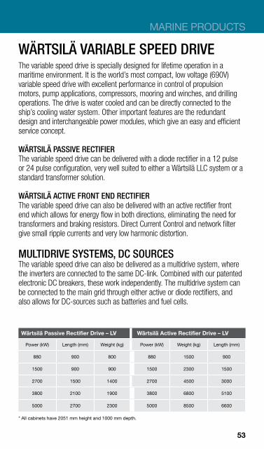
WÄRTSILÄ VARIABLE SPEED DRIVE The variable speed drive is specially designed for lifetime operation in a maritime environment. It is the world’s most compact, low voltage (690V) variable speed drive with excellent performance in control of propulsion motors, pump applications, compressors, mooring and winches, and drilling operations. The drive is water cooled and can be directly connected to the ship’s cooling water system. Other important features are the redundant design and interchangeable power modules, which give an easy and efficient service concept.
WÄRTSILÄ PASSIVE RECTIFIER The variable speed drive can be delivered with a diode rectifier in a 12 pulse or 24 pulse configuration, very well suited to either a Wärtsilä LLC system or a standard transformer solution.
WÄRTSILÄ ACTIVE FRONT END RECTIFIER The variable speed drive can also be delivered with an active rectifier front end which allows for energy flow in both directions, eliminating the need for transformers and braking resistors. Direct Current Control and network filter give small ripple currents and very low harmonic distortion.
MULTIDRIVE SYSTEMS, DC SOURCES The variable speed drive can also be delivered as a multidrive system, where the inverters are connected to the same DC-link. Combined with our patented electronic DC breakers, these work independently. The multidrive system can be connected to the main grid through either active or diode rectifiers, and also allows for DC-sources such as batteries and fuel cells.
Wärtsilä Passive Rectifier Drive – LV Wärtsilä Active Rectifier Drive – LV
Power (kW) Length (mm) Weight (kg) Power (kW) Weight (kg) Length (mm)
880 900 800 880 1500 900
1500 900 900 1500 2300 1500
2700 1500 1400 2700 4500 3000
3800 2100 1900 3800 6800 5100
5000 2700 2300 5000 8500 6600
* All cabinets have 2051 mm height and 1000 mm depth.
53

POWER ELECTRIC SYSTEMS
WÄRTSILÄ SWITCHBOARDS Wärtsilä low and medium voltage switchboard systems are optimised for marine use.
When developing our switchboard systems, the need for easy installation and maintenance is a key consideration. The system is module-based and, therefore, very flexible. Later extensions can also be easily added.
WÄRTSILÄ MARINE SWITCHBOARD – LV Technical data Rated voltage (V) 690 Short circuit test IEC 439–1
Surge current (peak) kA ................................................................... 176 Prospective current (RMS) kA ............................................................. 80 Thermal rated current (1s) .................................................................. 80 Bus bar (A) .................................................................................... 4000
54
MARINE PRODUCTS
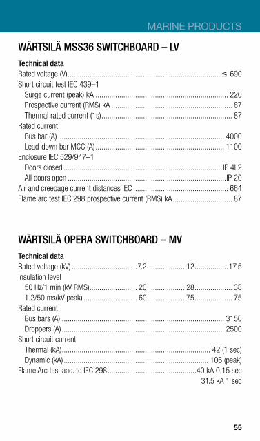
WÄRTSILÄ MSS36 SWITCHBOARD – LV Technical data Rated voltage (V) ............................................................................. 690 Short circuit test IEC 439–1
Surge current (peak) kA ................................................................... 220 Prospective current (RMS) kA ............................................................. 87 Thermal rated current (1s) .................................................................. 87
Rated current Bus bar (A) .................................................................................... 4000 Lead-down bar MCC (A) ................................................................. 1100
Enclosure IEC 529/947–1 Doors closed ................................................................................ IP 4L2 All doors open ................................................................................IP 20
Air and creepage current distances IEC ................................................ 664 Flame arc test IEC 298 prospective current (RMS) kA.............................. 87
WÄRTSILÄ OPERA SWITCHBOARD – MV Technical data Rated voltage (kV) .................................7.2 ................... 12 .................17.5 Insulation level
50 Hz/1 min (kV RMS) ........................ 20 ................... 28 ................... 38 1.2/50 ms(kV peak) ........................... 60 ................... 75 ................... 75
Rated current Bus bars (A) .................................................................................. 3150 Droppers (A) .................................................................................. 2500
Short circuit current Thermal (kA) ........................................................................... 42 (1 sec) Dynamic (kA) ......................................................................... 106 (peak)
Flame Arc test aac. to IEC 298 .............................................40 kA 0.15 sec 31.5 kA 1 sec
55
30 40 60 80
Speed [rpm]
102–127
99–124
84–105
90–105
91–114
76–95
61–76
68–80
68–84
87–102
92–102
142–167
124–146
80-97
69-84
70–80
80–105
8 15 20 104 63Power [MW]
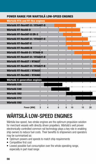
Wärtsilä RT-flex48T-D / RTA48T-D
Wärtsilä RT-flex50-D
Wärtsilä RT-flex58T-D / RTA58T-D
Wärtsilä RT-flex58T-E
Wärtsilä RT-flex60C-B
Wärtsilä RT-flex68-D / RTA68-D
Wärtsilä RT-flex84T-D / RTA84T-D
Wärtsilä RT-flex82T / RTA82T
Wärtsilä RT-flex82T-B / RTA82T-B
Wärtsilä RT-flex82C / RTA82C
Wärtsilä RT-flex96C / RTA96C
Wärtsilä X35
Wärtsilä X40
Wärtsilä X62
Wärtsilä X72
Wärtsilä X92
POWER RANGE FOR WARTSILÄ LOW-SPEED ENGINES
Wärtsilä RT-flex58T-D ER-3
Wärtsilä X-generation engines
Wärtsilä RTA and RT-flex engines
WÄRTSILÄ LOW-SPEED ENGINES Wärtsila low-speed, two-stroke engines are the optimum propulsion solution for merchant vessels with directly driven propellers. Wärtsilä’s well proven electronically-controlled common-rail technology plays a key role in enabling ship owners to reduce fuel costs. Their benefits to shipowners and operators may be summarised as: z Optimum powers and speeds to match ship requirements z Competitive first cost z Lowest possible fuel consumption over the whole operating range,
especially in part-load range
56
8 15 20104 63Power [MW]
Wärtsilä RT-flex48T-D / RTA48T-D
Wärtsilä RT-flex50-D
Wärtsilä RT-flex58T-D / RTA58T-D
Wärtsilä RT-flex58T-E
Wärtsilä RT-flex60C-B
Wärtsilä RT-flex68-D / RTA68-D
Wärtsilä RT-flex84T-D / RTA84T-D
Wärtsilä RT-flex82T / RTA82T
Wärtsilä RT-flex82T-B / RTA82T-B
Wärtsilä RT-flex82C / RTA82C
Wärtsilä RT-flex96C / RTA96C
Wärtsilä X35
Wärtsilä X40
Wärtsilä X62
Wärtsilä X72
Wärtsilä X92
POWER RANGE FOR WARTSILÄ LOW-SPEED ENGINES
Wärtsilä RT-flex58T-D ER-3
Wärtsilä X-generation engines
Wärtsilä RTA and RT-flex engines
MARINE PRODUCTS
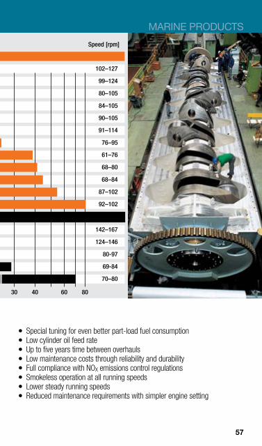
Speed [rpm]
102–127
99–124
80–105
84–105
90–105
91–114
76–95
61–76
68–80
68–84
87–102
92–102
142–167
124–146
80-97
69-84
70–80
30 40 60 80
z Special tuning for even better part-load fuel consumption z Low cylinder oil feed rate z Up to five years time between overhauls z Low maintenance costs through reliability and durability z Full compliance with NOX emissions control regulations z Smokeless operation at all running speeds z Lower steady running speeds z Reduced maintenance requirements with simpler engine setting
57
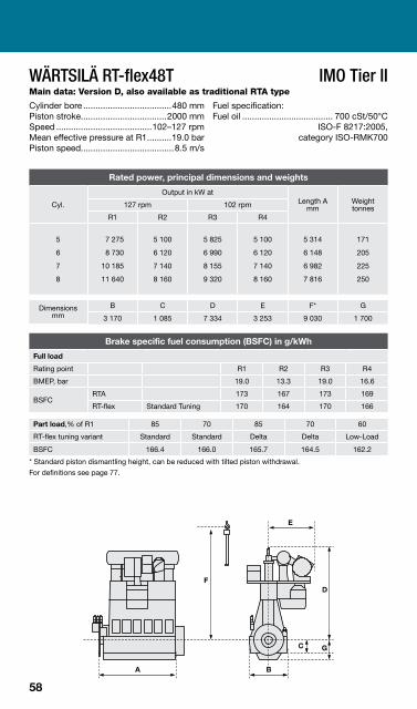
WÄRTSILÄ RT-flex48T IMO Tier II Main data: Version D, also available as traditional RTA type
Cylinder bore ....................................480 mm Fuel specification: Piston stroke...................................2000 mm Fuel oil ..................................... 700 cSt/50°C Speed .......................................102–127 rpm ISO-F 8217:2005,Mean effective pressure at R1..........19.0 bar category ISO-RMK700 Piston speed......................................8.5 m/s
Rated power, principal dimensions and weights
Output in kW at
Cyl. Length A mm
Weight tonnes 127 rpm 102 rpm
R1 R2 R3 R4
5
6
7
8
7 275
8 730
10 185
11 640
5 100
6 120
7 140
8 160
5 825
6 990
8 155
9 320
5 100
6 120
7 140
8 160
5 314
6 148
6 982
7 816
171
205
225
250
Dimensions mm
B C D E F* G
3 170 1 085 7 334 3 253 9 030 1 700
Brake specific fuel consumption (BSFC) in g/kWh
Full load
Rating point R1 R2 R3 R4
BMEP, bar 19.0 13.3 19.0 16.6
BSFC RTA 173 167 173 169
RT-flex Standard Tuning 170 164 170 166
Part load,% of R1 85 70 85 70 60
RT-flex tuning variant Standard Standard Delta Delta Low-Load
BSFC 166.4 166.0 165.7 164.5 162.2
* Standard piston dismantling height, can be reduced with tilted piston withdrawal. For definitions see page 77.
58

MARINE PRODUCTS
WÄRTSILÄ RT-flex48T IMO Tier II Main data: Version D, also available as traditional RTA type
Economy Ratings
Rated power, principal dimensions and weights
Cyl. Output in kW at 127 rpm
Length A mm Weight tonnes ER1 ER2
5
6
7
8
6 900
8 280
9 660
11 040
6 550
7 860
13 125
10 480
5 314
6 148
6 982
7 816
171
205
225
250
Dimensions mm
B C D E F* G
3 170 1 085 7 334 3 253 9 030 1 700
Brake specific fuel consumption (BSFC) in g/kWh
Rating point Tuning variant Load ER1 ER2
BMEP, bar 18.0 17.1
BSFC
RTA 100% 171.4 170.0
RT-flex Standard Tuning 100% 168.4 167.0
RT-flex Standard Tuning 85% 164.8 163.4
RT-flex Standard Tuning 70% 164.4 163.0
RT-flex Delta Tuning 85% 164.3 163.1
RT-flex Delta Tuning 70% 163.3 162.3
RT-flex Low-Load Tuning 60% 161.0 160.5
* Standard piston dismantling height, can be reduced with tilted piston withdrawal. For definitions see page 77.
Engine
layout field
59
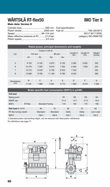
WÄRTSILÄ RT-flex50 IMO Tier II Main data: Version D
Cylinder bore ....................................500 mm Fuel specification: Piston stroke...................................2050 mm Fuel oil ..................................... 700 cSt/50°C Speed .........................................99–124 rpm ISO-F 8217:2005,Mean effective pressure at R1..........21.0 bar category ISO-RMK700 Piston speed......................................8.5 m/s
Rated power, principal dimensions and weights
Output in kW at
Cyl. Length A mm
Length A* mm
Weight tonnes 124 rpm 99 rpm
R1 R2 R3 R4
5
6
7
8
8 725
10 470
12 215
13 960
6 100
7 320
8 540
9 760
6 975
8 370
9 765
11 160
6 100
7 320
8 540
9 760
5 582
6 462
7 342
8 222
6 952
7 950
200
225
255
280
Dimensions mm
B C D E E* F1 G
3 150 1 088 7 646 3 710 1 955 9 270 1 636
Brake specific fuel consumption (BSFC) in g/kWh
Full load
Rating point R1 R2 R3 R4
BMEP, bar 21.0 14.7 21.0 18.4
BSFC RT-flex Standard Tuning 170 164 170 166
Part load,% of R1 85 70 85 70 60
RT-flex tuning variant Standard Standard Delta Delta Low-Load
BSFC 166.4 166.0 165.7 164.5 162.2
1) Standard piston dismantling height, can be reduced with tilted piston withdrawal. For definitions see page 77.
60
MARINE PRODUCTS
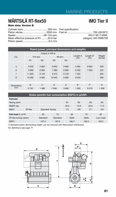
WÄRTSILÄ RT-flex50 IMO Tier II Main data: Version B
Cylinder bore ....................................500 mm Fuel specification: Piston stroke...................................2050 mm Fuel oil ..................................... 700 cSt/50°C Speed .........................................99–124 rpm ISO-F 8217:2005,Mean effective pressure at R1..........20.0 bar category ISO-RMK700 Piston speed......................................8.5 m/s
Rated power, principal dimensions and weights
Output in kW at
Cyl. Length A mm
Length A* mm
Weight tonnes 124 rpm 99 rpm
R1 R2 R3 R4
5
6
7
8
8 300
9 960
11 620
13 280
5 800
6 960
8 120
9 280
6 650
7 980
9 310
10 640
5 800
6 960
8 120
9 280
5 582
6 462
7 342
8 222
6 850
7 900
200
225
255
280
Dimensions mm
B C D E E* F1 G
3 150 1 088 7 646 3 690 1 955 9 270 1 636
Brake specific fuel consumption (BSFC) in g/kWh
Full load
Rating point R1 R2 R3 R4
BMEP, bar 20.0 13.9 20.0 17.5
BSFC RT-flex Standard Tuning 171 165 171 167
Part load,% of R1 85 70 85 70 60
RT-flex tuning variant Standard Standard Delta Delta Low-Load
BSFC 167.4 167.0 166.7 165.5 163.2
1) Standard piston dismantling height, can be reduced with tilted piston withdrawal. For definitions see page 77
61

WÄRTSILÄ RT-flex58T-D ER-3 IMO Tier II Main data: Version D
Cylinder bore ....................................550 mm Fuel specification: Piston stroke...................................2416 mm Fuel oil ..................................... 700 cSt/50°C Speed .........................................80–105 rpm ISO-F 8217:2005,Mean effective pressure at R1..........20.2 bar category ISO-RMK700 Piston speed......................................8.5 m/s
Rated power, principal dimensions and weights
Output in kW at
Cyl. Length A mm
Weight tonnes 105 rpm 80 rpm
R1 R2 R3 R4
5
6
7
10 175
12 210
14 245
7 100
8 520
9 940
7 750
9 300
10 850
5 400
6 480
7 560
6 381
7 387
8 393
281
322
377
Dimensions mm
B C D E F* G
3 820 1 300 8 822 3 475 10 880 2 000
Brake specific fuel consumption (BSFC) in g/kWh
Full load
Rating point R1 R2 R3 R4
BMEP, bar 20.2 14.1 20.2 14.1
BSFC RT-flex Standard Tuning** 167.0 161.0 167.0 161.0
Part load,% of R1 85 70 85 70 60
RT-flex tuning variant Standard Standard Delta Delta Low-Load
BSFC 163.4 163.0 162.7 161.5 159.2
* Standard piston dismantling height, can be reduced with tilted piston withdrawal. ** These BSFC values are for engines equipped with the latest high-efficiency turbochargers. Application of the previous generation of turbochargers leads to BSFC values that are 2 g/kWh higher. For definitions see page 77.
62

MARINE PRODUCTS
WÄRTSILÄ RT-flex58T IMO Tier II Main data: Version E
Cylinder bore ....................................580 mm Fuel specification: Piston stroke...................................2416 mm Fuel oil ..................................... 700 cSt/50°C Speed .........................................90–105 rpm ISO-F 8217:2005,Mean effective pressure at R1.............21 bar category ISO-RMK700 Piston speed......................................8.5 m/s
Rated power, principal dimensions and weights
Output in kW at
Cyl. Length A mm
Weight tonnes 105 rpm 90 rpm
R1 R2 R3 R4
5
6
7
8
11 750
14 100
16 450
18 800
7 900
9 480
11 060
12 640
10 075
12 090
14 105
16 120
7 900
9 480
11 060
12 640
6 381
7 387
8 393
9 399
281
322
377
418
Dimensions mm
B C D E F* G
3 820 1 300 8 822 3 475 10 880 2 000
Brake specific fuel consumption (BSFC) in g/kWh
Full load
Rating point R1 R2 R3 R4
BMEP, bar 21.0 14.1 21.0 16.5
BSFC RT-flex Standard Tuning 169 163 169 163
Part load,% of R1 85 70 85 70 60
RT-flex tuning variant Standard Standard Delta Delta Low-Load
BSFC 165.4 165.0 164.7 163.5 161.2
* Standard piston dismantling height, can be reduced with tilted piston withdrawal. For definitions see page 77.
63

WÄRTSILÄ RT-flex58T IMO Tier II Main data: Version D, also available as traditional RTA type
Cylinder bore ....................................580 mm Fuel specification: Piston stroke...................................2416 mm Fuel oil ..................................... 700 cSt/50°C Speed .........................................84–105 rpm ISO-F 8217:2005,Mean effective pressure at R1..........20.2 bar category ISO-RMK700 Piston speed......................................8.5 m/s
Rated power, principal dimensions and weights
Output in kW at
Cyl. Length A mm
Weight tonnes 105 rpm 84 rpm
R1 R2 R3 R4
5
6
7
8
11 300
13 560
15 820
18 080
7 900
9 480
11 060
12 640
9 050
10 860
12 670
14 480
7 900
9 480
11 060
12 640
6 381
7 387
8 393
9 399
281
322
377
418
Dimensions mm
B C D E F* G
3 820 1 300 8 822 3 475 10 880 2 000
Brake specific fuel consumption (BSFC) in g/kWh
Full load
Rating point R1 R2 R3 R4
BMEP, bar 20.2 14.1 20.2 17.7
BSFC RTA 174 168 174 170
RT-flex Standard Tuning** 169 163 169 165
Part load,% of R1 85 70 85 70 60
RT-flex tuning variant Standard Standard Delta Delta Low-Load
BSFC 165.4 165.0 164.7 163.5 161.2
* Standard piston dismantling height, can be reduced with tilted piston withdrawal. ** These BSFC values are for engines equipped with the latest high-efficiency turbochargers. Application of the previous generation of turbochargers leads to BSFC values that are 2 g/kWh higher. For definitions see page 77.
64

MARINE PRODUCTS
WÄRTSILÄ RT-flex60C IMO Tier II Main data: Version B
Cylinder bore ....................................600 mm Fuel specification: Piston stroke...................................2250 mm Fuel oil ..................................... 700 cSt/50°C Speed .........................................91–114 rpm ISO-F 8217:2005,Mean effective pressure at R1..........20.0 bar category ISO-RMK700 Piston speed......................................8.6 m/s
Rated power, principal dimensions and weights
Output in kW at
Cyl. Length A mm
Weight tonnes 114 rpm 91 rpm
R1 R2 R3 R4
5
6
7
8
9
12 100
14 520
16 940
19 360
21 780
8 450
10 140
11 830
13 520
15 210
9 650
11 580
13 510
15 440
17 370
8 450
10 140
11 830
13 520
15 210
6 638
7 678
8 718
9 758
10 798
268
322
377
428
480
Dimensions mm
B C D E F* G
3 700 1 300 8 570 3 660 10 500 1 955
Brake specific fuel consumption (BSFC) in g/kWh
Full load
Rating point R1 R2 R3 R4
BMEP, bar 20.0 14.0 20.0 17.5
BSFC RT-flex Standard Tuning 171 165 171 167
Part load,% of R1 85 70 85 70 60
RT-flex tuning variant Standard Standard Delta Delta Low-Load
BSFC 167.4 167.0 166.7 165.5 163.2
* Standard piston dismantling height, can be reduced with tilted piston withdrawal. For definitions see page 77.
65
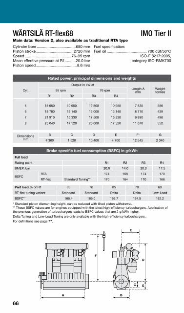
WÄRTSILÄ RT-flex68 IMO Tier II Main data: Version D, also available as traditional RTA type
Cylinder bore ....................................680 mm Fuel specification: Piston stroke...................................2720 mm Fuel oil ..................................... 700 cSt/50°C Speed ...........................................76–95 rpm ISO-F 8217:2005,Mean effective pressure at R1..........20.0 bar category ISO-RMK700 Piston speed......................................8.6 m/s
Rated power, principal dimensions and weights
Output in kW at
Cyl. Length A mm
Weight tonnes 95 rpm 76 rpm
R1 R2 R3 R4
5
6
7
8
15 650
18 780
21 910
25 040
10 950
13 140
15 330
17 520
12 500
15 000
17 500
20 000
10 950
13 140
15 330
17 520
7 530
8 710
9 890
11 070
386
439
496
552
Dimensions mm
B C D E F* G
4 300 1 520 10 400 4 700 12 545 2 340
Brake specific fuel consumption (BSFC) in g/kWh
Full load
Rating point R1 R2 R3 R4
BMEP, bar 20.0 14.0 20.0 17.5
BSFC RTA 174 168 174 170
RT-flex Standard Tuning** 170 164 170 166
Part load,% of R1 85 70 85 70 60
RT-flex tuning variant Standard Standard Delta Delta Low-Load
BSFC** 166.4 166.0 165.7 164.5 162.2
* Standard piston dismantling height, can be reduced with tilted piston withdrawal. ** These BSFC values are for engines equipped with the latest high-efficiency turbochargers. Application of the previous generation of turbochargers leads to BSFC values that are 2 g/kWh higher. Delta Tuning and Low-Load Tuning are only available with the high-efficiency turbochargers. For definitions see page 77.
66
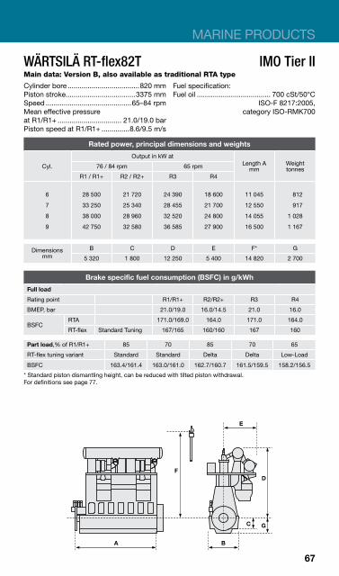
MARINE PRODUCTS
WÄRTSILÄ RT-flex82T IMO Tier II Main data: Version B, also available as traditional RTA type
Cylinder bore ....................................820 mm Fuel specification: Piston stroke...................................3375 mm Fuel oil ..................................... 700 cSt/50°C Speed ...........................................65–84 rpm ISO-F 8217:2005,Mean effective pressure category ISO-RMK700 at R1/R1+ ................................ 21.0/19.0 bar Piston speed at R1/R1+ ..............8.6/9.5 m/s
Rated power, principal dimensions and weights
Output in kW at
Cyl. Length A mm
Weight tonnes 76 / 84 rpm 65 rpm
R1 / R1+ R2 / R2+ R3 R4
6
7
8
9
28 500
33 250
38 000
42 750
21 720
25 340
28 960
32 580
24 390
28 455
32 520
36 585
18 600
21 700
24 800
27 900
11 045
12 550
14 055
16 500
812
917
1 028
1 167
Dimensions mm
B C D E F* G
5 320 1 800 12 250 5 400 14 820 2 700
Brake specific fuel consumption (BSFC) in g/kWh
Full load
Rating point R1/R1+ R2/R2+ R3 R4
BMEP, bar 21.0/19.0 16.0/14.5 21.0 16.0
BSFC RTA 171.0/169.0 164.0 171.0 164.0
RT-flex Standard Tuning 167/165 160/160 167 160
Part load,% of R1/R1+ 85 70 85 70 65
RT-flex tuning variant Standard Standard Delta Delta Low-Load
BSFC 163.4/161.4 163.0/161.0 162.7/160.7 161.5/159.5 158.2/156.5
* Standard piston dismantling height, can be reduced with tilted piston withdrawal. For definitions see page 77.
67

WÄRTSILÄ RT-flex82T IMO Tier II Main data: Also available as traditional RTA type
Cylinder bore ....................................820 mm Fuel specification: Piston stroke...................................3375 mm Fuel oil ..................................... 700 cSt/50°C Speed ...........................................68–80 rpm ISO-F 8217:2005,Mean effective pressure category ISO-RMK700 at R1/R1+ ................................ 20.0/19.0 bar Piston speed at R1/R1+ ..............8.6/9.0 m/s
Rated power, principal dimensions and weights
Output in kW at
Cyl. Length A mm
Weight tonnes 76 / 80 rpm 68 rpm
R1 / R1+ R2 / R2+ R3 R4
6
7
8
9
27 120
31 640
36 160
40 680
21 720
25 340
28 960
32 580
24 300
28 350
32 400
36 450
21 720
25 340
28 960
32 580
11 045
12 550
14 055
16 500
812
917
1 028
1 167
Dimensions mm
B C D E F* G
5 320 1 800 12 250 5 400 14 820 2 700
Brake specific fuel consumption (BSFC) in g/kWh
Full load
Rating point R1/R1+ R2/R2+ R3 R4
BMEP, bar 20.0/19.0 16.0/14.5 20.0 17.9
BSFC RTA 171.0/169.0 164.0 171.0 164.0
RT-flex Standard Tuning** 168/166 162 168 165
Part load,% of R1/R1+ 85 70 85 70 65
RT-flex tuning variant Standard Standard Delta Delta Low-Load
BSFC** 164.4/162.4 164.0/162.0 163.7/161.7 162.5/160.5 159.7/157.7
* Standard piston dismantling height, can be reduced with tilted piston withdrawal. ** These BSFC values are for engines equipped with the latest high-efficiency turbochargers. Application of the previous generation of turbochargers leads to BSFC values that are 2 g/kWh higher. Delta Tuning and Low-Load Tuning are only available with the high-efficiency turbochargers. For definitions see page 77.
68

MARINE PRODUCTS
WÄRTSILÄ RT-flex82C IMO Tier II Main data: Also available as traditional RTA type
Cylinder bore ....................................820 mm Fuel specification: Piston stroke...................................2646 mm Fuel oil ..................................... 700 cSt/50°C Speed .........................................87–102 rpm ISO-F 8217:2005,Mean effective pressure category ISO-RMK700 at R1/R1+ ................................ 20.0/19.0 bar Piston speed at R1/R1+ ..............8.6/9.0 m/s
Rated power, principal dimensions and weights
Output in kW at
Cyl. Length A mm
Weight tonnes 97 / 102 rpm 87 rpm
R1 / R1+ R2 / R2+ R3 R4
6 7 8 9 10 11 12
27 120 31 640 36 160 40 680 45 200 49 720 54 240
21 720 25 340 28 960 32 580 36 200 39 820 43 440
24 300 28 350 32 400 36 450 40 500 44 550 48 600
21 720 25 340 28 960 32 580 36 200 39 820 43 440
11 045 12 550 14 055 16 500 18 005 19 510 21 015
745 840 935
1 005 1 145 1 230 1 335
Dimensions mm
B C D E F* G
4 570 1 600 10 930 5 400 12 700 2 310
Brake specific fuel consumption (BSFC) in g/kWh
Full load
Rating point R1/R1+ R2/R2+ R3 R4
BMEP, bar 20.0/19.0 16.0/15.2 20.0 17.9
BSFC RTA 177/175 171 177 174
RT-flex Standard Tuning** 173/171 167 173 170
Part load,% of R1/R1+ 85 70 85 70 65
RT-flex tuning variant Standard Standard Delta Delta Low-Load
BSFC** 169.4/167.4 169.0/167.0 168.7/166.7 167.5/165.5 164.7/162.7
* Standard piston dismantling height, can be reduced with tilted piston withdrawal. ** These BSFC values are for engines equipped with the latest high-efficiency turbochargers. Application of the previous generation of turbochargers leads to BSFC values that are 2 g/kWh higher. Delta Tuning and Low-Load Tuning are only available with the high-efficiency turbochargers. For definitions see page 77.
69

WÄRTSILÄ RT-flex84T IMO Tier II Main data: Version D, also available as traditional RTA type
Cylinder bore ....................................840 mm Fuel specification: Piston stroke...................................3150 mm Fuel oil ..................................... 700 cSt/50°C Speed ...........................................61–76 rpm ISO-F 8217:2005,Mean effective pressure at R1..........19.0 bar category ISO-RMK700 Piston speed......................................8.0 m/s
Rated power, principal dimensions and weights
Output in kW at
Cyl. Length A mm
Weight tonnes 76 rpm 61 rpm
R1 R2 R3 R4
5
6
7
8
9
21 000
25 200
29 400
33 600
37 800
14 700
17 640
20 580
23 520
26 460
16 850
20 220
23 590
26 960
30 330
14 700
17 640
20 580
23 520
26 460
9 695
11 195
12 695
15 195
16 695
740
870
990
1 140
1 260
Dimensions mm
B C D E F* G
5 000 1 800 12 150 5 105 14 500 2 700
Brake specific fuel consumption (BSFC) in g/kWh
Full load
Rating point R1 R2 R3 R4
BMEP, bar 19.0 13.3 19.0 16.6
BSFC RTA 173 167 173 169
RT-flex Standard Tuning 171 165 171 167
Part load,% of R1 85 70 85 70 65
RT-flex tuning variant Standard Standard Delta Delta Low-Load
BSFC 167.4 167.0 166.7 165.5 162.7
* Standard piston dismantling height, can be reduced with tilted piston withdrawal. For definitions see page 77.
70
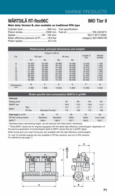
MARINE PRODUCTS
WÄRTSILÄ RT-flex96C IMO Tier II Main data: Version B, also available as traditional RTA type
Cylinder bore ....................................960 mm Fuel specification: Piston stroke...................................2500 mm Fuel oil ..................................... 700 cSt/50°C Speed ....................................... 92 - 102 rpm ISO-F 8217:2005,Mean effective pressure at R1..........18.6 bar category ISO-RMK700 Piston speed......................................8.5 m/s
Rated power, principal dimensions and weights
Cyl.
Output in kW at Length A
mm Weight tonnes 102 rpm 92 rpm
R1 R2 R3 R4
6 7 8 9 10 11 12 13 14
34 320 40 040 45 760 51 480 57 200 62 920 68 640 74 360 80 080
24 000 28 000 32 000 36 000 40 000 44 000 48 000 52 000 56 000
30 960 36 120 41 280 46 440 51 600 56 760 61 920 67 080 72 240
24 000 28 000 32 000 36 000 40 000 44 000 48 000 52 000 56 000
12 240 13 920 16 510 18 190 19 870 21 550 23 230 24 910 26 590
1 160 1 290 1 470 1 620 1 760 1 910 2 050 2 160 2 300
Dimensions mm
B C D E F* G
4 480 1 800 10 925 5 380 12 950 2 594
Brake specific fuel consumption (BSFC) in g/kWh
Full load
Rating point R1 R2 R3 R4 BMEP, bar 18.6 13.0 18.6 14.4
BSFC RTA 177 171 177 171 RT-flex Standard Tuning** 172 166 172 166
Part load,% of R1 85 70 85 70 65 RT-flex tuning variant Standard Standard Delta Delta Low-Load BSFC** 168.4 168.0 167.7 166.5 163.7
* Standard piston dismantling height, can be reduced with tilted piston withdrawal. ** These BSFC values are for engines equipped with the latest high-efficiency turbochargers. Application of the previous generation of turbochargers leads to BSFC values that are 3 g/kWh higher. Delta Tuning and Low-Load Tuning are only available with the high-efficiency turbochargers. 13- and 14-cylinder engines are only available in RT-flex versions, and not in RTA versions. For definitions see page 77.
71

WÄRTSILÄ X35 IMO Tier II Main data:
Cylinder bore ....................................350 mm Fuel specification: Piston stroke...................................1550 mm Fuel oil ..................................... 700 cSt/50°C Speed .......................................142–167 rpm ISO-F 8217:2005,Mean effective pressure at R1..........21.0 bar category ISO-RMK700 Piston speed......................................8.6 m/s
Rated power, principal dimensions and weights
Output in kW at
Cyl. Length A mm
Weight tonnes 167 rpm 142 rpm
R1 R2 R3 R4
5
6
7
8
4 350
5 220
6 090
6 960
3 475
4 170
4 865
5 560
3 700
4 440
5 180
5 920
3 475
4 170
4 865
5 560
4 434
5 046
5 658
6 270
74
84
95
105
Dimensions mm
B C D E F* G
2 264 830 5 556 1 220 6 850 1 326
Brake specific fuel consumption (BSFC) in g/kWh
Full load
Rating point R1 R2 R3 R4
BMEP, bar 21.0 16.8 21.0 19.8
BSFC Standard Tuning 176 170 176 174
Part load,% of R1 85 70 85 70 60
Tuning variant Standard Standard Delta Delta Low-Load
BSFC 172.4 172.0 171.7 170.5 168.2
* Standard piston dismantling height, can be reduced with tilted piston withdrawal. For definitions see page 77.
72
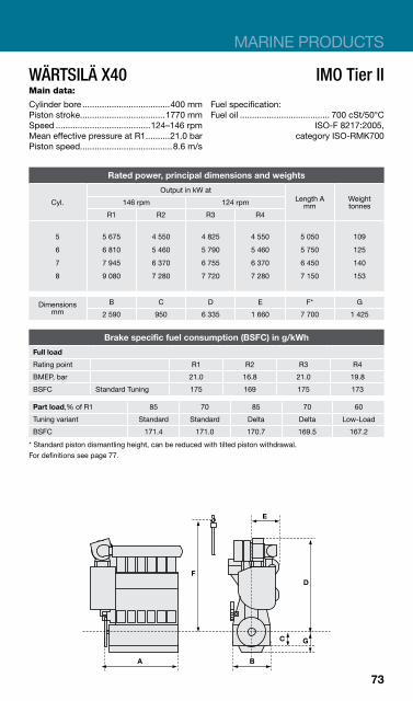
MARINE PRODUCTS
WÄRTSILÄ X40 IMO Tier II Main data:
Cylinder bore ....................................400 mm Fuel specification: Piston stroke...................................1770 mm Fuel oil ..................................... 700 cSt/50°C Speed .......................................124–146 rpm ISO-F 8217:2005,Mean effective pressure at R1..........21.0 bar category ISO-RMK700 Piston speed......................................8.6 m/s
Rated power, principal dimensions and weights
Output in kW at
Cyl. Length A mm
Weight tonnes 146 rpm 124 rpm
R1 R2 R3 R4
5
6
7
8
5 675
6 810
7 945
9 080
4 550
5 460
6 370
7 280
4 825
5 790
6 755
7 720
4 550
5 460
6 370
7 280
5 050
5 750
6 450
7 150
109
125
140
153
Dimensions mm
B C D E F* G
2 590 950 6 335 1 660 7 700 1 425
Brake specific fuel consumption (BSFC) in g/kWh
Full load
Rating point R1 R2 R3 R4
BMEP, bar 21.0 16.8 21.0 19.8
BSFC Standard Tuning 175 169 175 173
Part load,% of R1 85 70 85 70 60
Tuning variant Standard Standard Delta Delta Low-Load
BSFC 171.4 171.0 170.7 169.5 167.2
* Standard piston dismantling height, can be reduced with tilted piston withdrawal. For definitions see page 77.
73

WÄRTSILÄ X62 IMO Tier II Main data
Cylinder bore ....................................620 mm Fuel specification: Piston stroke...................................2658 mm Fuel oil ..................................... 700 cSt/50°C Speed .........................................80–103 rpm ISO-F 8217:2005,Mean effective pressure category ISO-RMK700 at R1/R1+ ................................ 20.5/19.3 bar Piston speed at R1/R1+ ..............8.6/9.1 m/s
Rated power, principal dimensions and weights
Output in kW at
Cyl. Length A mm
Weight tonnes 97 / 103 rpm 80 rpm
R1 / R1+ R2 / R2+ R3 R4
4
5
6
7
8
10 640
13 300
15 960
18 620
21 280
8 000
10 000
12 000
14 000
16 000
8 760
10 950
13 140
15 330
17 520
6 600
8 250
9 900
11 550
13 200
5 895
7 030
8 110
9 215
10 320
270
325
377
435
482
Dimensions mm
B C D E F* G
4 180 1 360 10 050 3 915 11 950 2 070
Brake specific fuel consumption (BSFC) in g/kWh
Full load
Rating point R1/R1+ R2/R2+ R3 R4
BMEP, bar 20.5/19.3 15.4/14.5 20.5 15.4
BSFC Standard Tuning 168/167 161 168 161
Part load,% of R1/R1+ 85 70 85 70 65
Tuning variant Standard Standard Delta Delta Low-Load
BSFC 164.4/163.4 164.0/163.0 163.7/162.7 162.5/161.5 159.2/158.4
* Standard piston dismantling height, can be reduced with tilted piston withdrawal. For definitions see page 77.
74

MARINE PRODUCTS
WÄRTSILÄ X72 IMO Tier II Main data
Cylinder bore ....................................720 mm Fuel specification: Piston stroke...................................3086 mm Fuel oil ..................................... 700 cSt/50°C Speed ...........................................69–89 rpm ISO-F 8217:2005,Mean effective pressure category ISO-RMK700 at R1/R1+ ................................ 20.5/19.4 bar Piston speed at R1/R1+ ..............8.6/9.2 m/s
Rated power, principal dimensions and weights
Output in kW at
Cyl. Length A mm
Weight tonnes 84 / 89 rpm 69 rpm
R1 / R1+ R2 / R2+ R3 R4
4
5
6
7
8
14 440
18 050
21 660
25 270
28 880
10 800
13 500
16 200
18 900
21 600
11 880
14 850
17 820
20 790
23 760
8 880
11 100
13 320
15 540
17 760
6 770
8 060
9 350
10 645
11 935
407
481
561
642
716
Dimensions mm
B C D E F* G
4 850 1 580 11 640 4 380 13 950 2 380
Brake specific fuel consumption (BSFC) in g/kWh
Full load
Rating point R1/R1+ R2/R2+ R3 R4
BMEP, bar 20.5/19.4 15.4/14.5 20.5 15.4
BSFC Standard Tuning 168/167 161 168 161
Part load,% of R1/R1+ 85 70 85 70 65
Tuning variant Standard Standard Delta Delta Low-Load
BSFC 164.4/163.4 164.0/163.0 163.7/162.7 162.5/161.5 159.2/158.4
* Standard piston dismantling height, can be reduced with tilted piston withdrawal. For definitions see page 77.
75
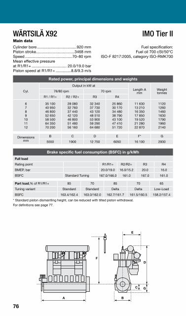
WÄRTSILÄ X92 IMO Tier II Main data
Cylinder bore ....................................920 mm Fuel specification: Piston stroke...................................3468 mm Fuel oil 700 cSt/50°C Speed ...........................................70–80 rpm ISO-F 8217:2005, category ISO-RMK700 Mean effective pressure at R1/R1+ ................................ 20.0/19.0 bar Piston speed at R1/R1+ ..............8.8/9.3 m/s
Rated power, principal dimensions and weights
Output in kW at
Cyl. Length A mm
Weight tonnes 76/80 rpm 70 rpm
R1 / R1+ R2 / R2+ R3 R4
6 7 8 9 10 11 12
35 100 40 950 46 800 52 650 58 500 64 350 70 200
28 080 32 760 37 440 42 120 46 800 51 480 56 160
32 340 37 730 43 120 48 510 53 900 59 290 64 680
25 860 30 170 34 480 38 790 43 100 47 410 51 720
11 630 13 210 16 350 17 850 19 520 21 280 22 870
1120 1260 1460 1630 1790 1960 2140
Dimensions mm
B C D E F* G
5550 1900 12 750 6050 16 100 2930
Brake specific fuel consumption (BSFC) in g/kWh
Full load
Rating point R1/R1+ R2/R2+ R3 R4
BMEP, bar 20.0/19.0 16.0/15.2 20.0 16.0
BSFC Standard Tuning 167.0/166.0 161.0 167.0 161.0
Part load,% of R1/R1+ 85 70 85 70 65
Tuning variant Standard Standard Delta Delta Low-Load
BSFC 163.4/162.4 163.0/162.0 162.7/161.7 161.5/160.5 158.2/157.4
* Standard piston dismantling height, can be reduced with tilted piston withdrawal. For definitions see page 77.
76
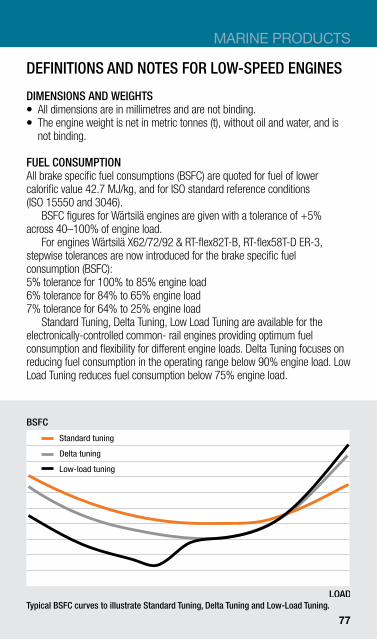
MARINE PRODUCTS
DEFINITIONS AND NOTES FOR LOW-SPEED ENGINES
DIMENSIONS AND WEIGHTS z All dimensions are in millimetres and are not binding. z The engine weight is net in metric tonnes (t), without oil and water, and is
not binding.
FUEL CONSUMPTION All brake specific fuel consumptions (BSFC) are quoted for fuel of lower calorific value 42.7 MJ/kg, and for ISO standard reference conditions (ISO 15550 and 3046).
BSFC figures for Wärtsilä engines are given with a tolerance of +5% across 40–100% of engine load.
For engines Wärtsilä X62/72/92 & RT-flex82T-B, RT-flex58T-D ER-3, stepwise tolerances are now introduced for the brake specific fuel consumption (BSFC): 5% tolerance for 100% to 85% engine load 6% tolerance for 84% to 65% engine load 7% tolerance for 64% to 25% engine load
Standard Tuning, Delta Tuning, Low Load Tuning are available for the electronically-controlled common- rail engines providing optimum fuel consumption and flexibility for different engine loads. Delta Tuning focuses on reducing fuel consumption in the operating range below 90% engine load. Low Load Tuning reduces fuel consumption below 75% engine load.
BSFC
Standard tuning
Delta tuning
Low-load tuning
LOAD Typical BSFC curves to illustrate Standard Tuning, Delta Tuning and Low-Load Tuning.
77

LOW-SPEED ENGINES ISO STANDARD REFERENCE CONDITIONS Total barometric pressure at R11.0 bar Suction air temperature ............................................ 25 °C Relative humidity ............................................ 30% Scavenge air cooling water temperature ................................ 29 °C
EMISSIONS All Wärtsilä low-speed engines included in this booklet are fully compliant with IMO Tier II NOX limits specified in Annex VI of the MARPOL 73/78. They can also be equipped with a SCR catalyst to meet IMO Tier III NOX emission levels and a scrubber to reduce SOX emissions to 0.1% – even with high sulphur fuels.
RATING POINTS FOR WÄRTSILÄ LOW-SPEED ENGINES The engine layout fields for Wärtsilä low-speed engines are defined by the power/speed rating points R1, R2, R3 and R4 (see diagram to the right). In certain engines, the layout field is extended to the points R1+ and R2+.
78
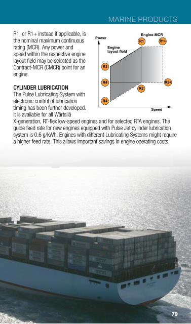
MARINE PRODUCTS
R1, or R1+ instead if applicable, is Engine-MCRPowerthe nominal maximum continuous
rating (MCR). Any power and speed within the respective engine layout field may be selected as the Contract-MCR (CMCR) point for an engine.
CYLINDER LUBRICATION The Pulse Lubricating System with electronic control of lubrication timing has been further developed. It is available for all Wärtsilä X-generation, RT-flex low-speed engines and for selected RTA engines. The guide feed rate for new engines equipped with Pulse Jet cylinder lubrication system is 0.6 g/kWh. Engines with different Lubricating Systems might require a higher feed rate. This allows important savings in engine operating costs.
79
Speed
Enginelayout field
R2+
R4
R1 R1+
R2
R3
R4
79
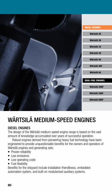
POWER RANGE FOR MEDIUM-SPEED ENGINESWÄRTSILÄ
kW 5000 10,000 15,000 20,000 25,000
Wärtsilä 34DF
Wärtsilä 50DF
Wärtsilä 20
Wärtsilä 26
Wärtsilä 32
Wärtsilä 38
Wärtsilä 46
Wärtsilä 46F
Wärtsilä 64
DIESEL ENGINES
DUAL-FUEL ENGINES
Wärtsilä 20DF
WÄRTSILÄ MEDIUM-SPEED ENGINES DIESEL ENGINES The design of the Wärtsilä medium-speed engine range is based on the vast amount of knowledge accumulated over years of successful operation.
Robust engines derived from pioneering heavy fuel technology have been engineered to provide unquestionable benefits for the owners and operators of Wärtsilä engines and generating sets: z Proven reliability z Low emissions z Low operating costs z Fuel flexibility Benefits for the shipyard include installation friendliness, embedded automation system, and built-on modularised auxiliary systems.
80
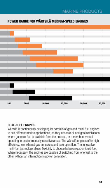
Wärtsilä 34DF
Wärtsilä 50DF
Wärtsilä 20
Wärtsilä 26
Wärtsilä 32
Wärtsilä 38
Wärtsilä 46
Wärtsilä 46F
Wärtsilä 64
DIESEL ENGINES
DUAL-FUEL ENGINES
Wärtsilä 20DF
MARINE PRODUCTS
POWER RANGE FOR WÄRTSILÄ MEDIUM-SPEED ENGINES
kW 5000 10,000 15,000 20,000 25,000
DUAL-FUEL ENGINES Wärtsilä is continuously developing its portfolio of gas and multi-fuel engines to suit different marine applications, be they offshore oil and gas installations where gaseous fuel is available from the process, or a merchant vessel operating in environmentally sensitive areas. The Wärtsilä engines offer high efficiency, low exhaust gas emissions and safe operation. The innovative multi-fuel technology allows flexibility to choose between gas or liquid fuel. When necessary, the engines are capable of switching from one fuel to the other without an interruption in power generation.
81
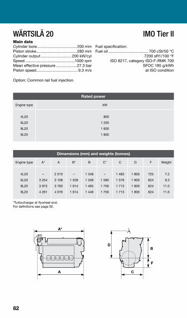
WÄRTSILÄ 20 Main data Cylinder bore ....................................200 mm Piston stroke.....................................280 mm Cylinder output............................ 200 kW/cyl Speed .............................................1000 rpm Mean effective pressure ...................27.3 bar Piston speed......................................9.3 m/s
Option: Common rail fuel injection.
IMO Tier II Fuel specification: Fuel oil .................................... 700 cSt/50 °C
7200 sR1/100 °F ISO 8217, category ISO-F-RMK 700
SFOC 185 g/kWh at ISO condition
Rated power
Engine type kW
4L20
6L20
8L20
9L20
800
1 200
1 600
1 800
Dimensions (mm) and weights (tonnes)
Engine type A* A B* B C* C D F Weight
4L20
6L20
8L20
9L20
–
3 254
3 973
4 261
2 510
3 108
3 783
4 076
–
1 528
1 614
1 614
1 348
1 348
1 465
1 449
–
1 580
1 756
1 756
1 483
1 579
1 713
1 713
1 800
1 800
1 800
1 800
725
624
624
624
7.2
9.3
11.0
11.6
*Turbocharger at flywheel end. For definitions see page 92.
82

MARINE PRODUCTS
WÄRTSILÄ 26 Main data Cylinder bore ....................................260 mm Piston stroke.....................................320 mm Cylinder output............................ 340 kW/cyl Speed .............................................1000 rpm Mean effective pressure ......................24 bar Piston speed....................................10.7 m/s
IMO Tier II Fuel specification: Fuel oil .................................... 700 cSt/50 °C
7200 sR1/100 °F ISO 8217, category ISO-F-RMK 700
SFOC 184 g/kWh at ISO condition
Rated power
Engine type kW
6L26
8L26
9L26
12V26
16V26
2 040
2 720
3 060
4 080
5 440
Dimensions (mm) and weights (tonnes)
Engine type A* A B* B C* C D F
dry sump F
wet sump Weight
dry sump Weight
wet sump
6L26 8L26 9L26
12V26 16V26
4 401 5 304 5 703 5 218 6 223
4 175 4 999 5 389 4 968 5 973
1 882 2 019 2 019 2 074 2 151
1 882 1 882 1 882 2 074 2 151
1 951 2 011 2 011 2 453 2 489
2 021 2 102 2 102 2 453 2 489
2 420 2 420 2 420 2 060 2 060
818 818 818 800 800
950 950 950
1 110 1 110
18.1 22.0 23.9 29.2 33.0
18.4 22.5 24.8 31.9 36.5
*Turbocharger at flywheel end. For definitions see page 92.
83

WÄRTSILÄ 32 Main data Cylinder bore ....................................320 mm Piston stroke.....................................400 mm Cylinder output........ 500 kW/cyl, 580 kW/cyl Speed ...............................................750 rpm Mean effective pressure ....24.9 bar, 28.9 bar Piston speed....................................10.0 m/s
Option: Common rail fuel injection.
IMO Tier II Fuel specification: Fuel oil .................................... 700 cSt/50 °C
7200 sR1/100 °F ISO 8217, category ISO-F-RMK 700
SFOC 176 g/kWh at ISO condition
Rated power
Engine type 500 kW/cyl 580 kW/cyl
6L32 7L32 8L32 9L32 12V32 16V32 18V32
3 000 3 500 4 000 4 500 6 000 8 000 9 000
3480 –
4640 5220 6960 9280
–
Dimensions (mm) and weights (tonnes)
Engine type A* A B* B C D F Weight
6L32 7L32 8L32 9L32 12V32 16V32 18V32
4 980 5 470 5 960 6 450 6 935 8 060 8 620
5 260 5 750 6 245 6 730 6 615 7 735 8 295
2 560 2 560 2 360 2 360 2 715 2 480 2 480
2 490 2 490 2 295 2 295 2 665 2 430 2 430
2 305 2 305 2 305 2 305 3 020 3 020 3 020
2 345 2 345 2 345 2 345 2 120 2 120 2 120
1 155 1 155 1 155 1 155 1 475 1 475 1 475
33.3 39.0 43.4 46.8 58.7 74.1 81.2
*Turbocharger at flywheel end. For definitions see page 92.
84

MARINE PRODUCTS
WÄRTSILÄ 38 Main data Cylinder bore ....................................380 mm Piston stroke.....................................475 mm Cylinder output............................ 725 kW/cyl Speed ..............................................600 rpm Mean effective pressure ...................26.9 bar Piston speed......................................9.5 m/s
IMO Tier II Fuel specification: Fuel oil .................................... 700 cSt/50 °C
7200 sR1/100 °F ISO 8217, category ISO-F-RMK 700
SFOC 176 g/kWh at ISO condition
Rated power
Engine type kW
6L38
8L38
9L38
12V38
16V38
4 350
5 800
6 525
8 700
11 600
Dimensions (mm) and weights (tonnes)
Engine type A* A B* B C D F Weight
6L38
8L38
9L38
12V38
16V38
6 345
7 960
8 560
7 461
9 018
6 215
7 844
8 444
7 344
8 904
2 830
2 996
2 996
3 080
3 281
2 830
2 972
2 972
3 080
3 281
2 122
2 209
2 209
3 030
3 030
3 135
3 135
3 135
2 855
2 855
1 115
1 115
1 115
1 435
1 435
51
63
72
88
110
* Turbocharger at flywheel end. For definitions see page 92.
85

WÄRTSILÄ 46 Main data Cylinder bore ....................................460 mm Piston stroke.....................................580 mm Cylinder output.......................... 1050 kW/cyl Speed ....................................... 500-514 rpm Mean effective pressure ......... 26.1-25.4 bar Piston speed.............................. 9.7, 9.9 m/s
Option: Common rail fuel injection.
IMO Tier II Fuel specification: Fuel oil ................................... 700 cSt/50 °C
7200 sR1/100 °F ISO 8217, category ISO-F-RMK 700
SFOC 173 g/kWh at ISO condition
Rated power
Engine type kW
12V46
16V46
12 600
16 800
Dimensions (mm) and weights (tonnes)
Engine type A* A B C D F Weight
12V46
16V46
10 540
13 185
10 420
13 060
3 890
4 400
4 055
4 730
3600
3600
1 500
1 500
176
220
* Turbocharger at flywheel end. For definitions see page 92.
86

MARINE PRODUCTS
WÄRTSILÄ 46F IMO Tier II Main data Cylinder bore ....................................460 mm Fuel specification: Piston stroke.....................................580 mm Fuel oil .................................... 700 cSt/50 °C Cylinder output......................... 1200 kW/cyl 7200 sR1/100 °F Speed ...............................................600 rpm ISO 8217, category ISO-F-RMK 700 Mean effective pressure ...................24.9 bar SFOC 170 g/kWh Piston speed................................... 11.6 m/s at ISO condition
Option: Lubricating oil Module integrated on engine.
Rated power
Engine type kW
6L46F 7L46F 8L46F 9L46F 12V46F 14V46F 16V46F
7 200 8 400 9 600
10 800 14 400 16 800 19 200
Dimensions (mm) and weights (tonnes)
Engine type A* A B C D F Weight
6L46F 7L46F 8L46F 9L46F 12V46F 14V46F 16V46F
8 430 9 260
10 080 10 900 10 080 11 650 12 700
8 620 9 440
10 260 11 080 10 150 11 729 12 779
3 500 3 800 3 800 3 800 3 820 4 243 4 243
2 930 2 950 2 950 2 950 4 050 4 678 4 678
3 750 3 750 3 750 3 750 3 800 3 800 3 800
1 430 1 430 1 430 1 430 1 620 1 620 1 620
97 113 124 140 173 216 233
* Turbocharger at flywheel end. For definitions see page 92.
87
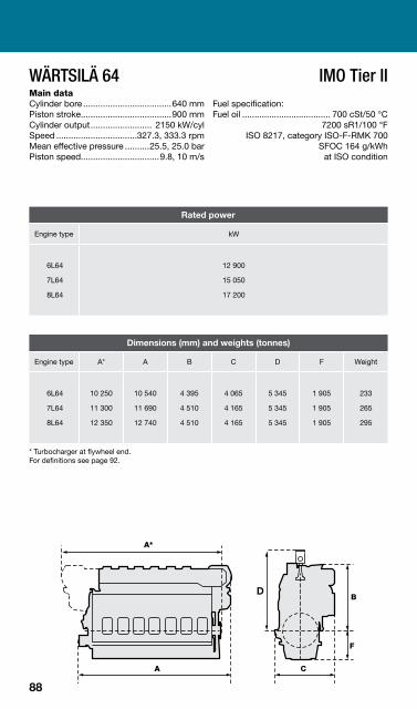
WÄRTSILÄ 64 Main data Cylinder bore ....................................640 mm Piston stroke.....................................900 mm Cylinder output......................... 2150 kW/cyl Speed .................................327.3, 333.3 rpm Mean effective pressure ..........25.5, 25.0 bar Piston speed................................9.8, 10 m/s
IMO Tier II Fuel specification: Fuel oil .................................... 700 cSt/50 °C
7200 sR1/100 °F ISO 8217, category ISO-F-RMK 700
SFOC 164 g/kWh at ISO condition
Rated power
Engine type kW
6L64
7L64
8L64
12 900
15 050
17 200
Dimensions (mm) and weights (tonnes)
Engine type A* A B C D F Weight
6L64
7L64
8L64
10 250
11 300
12 350
10 540
11 690
12 740
4 395
4 510
4 510
4 065
4 165
4 165
5 345
5 345
5 345
1 905
1 905
1 905
233
265
295
* Turbocharger at flywheel end. For definitions see page 92.
88
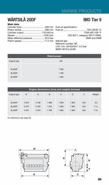
MARINE PRODUCTS
WÄRTSILÄ 20DF Main data Cylinder bore ...................................200 mm Piston stroke.....................................280 mm Cylinder output............................ 176 kW/cyl Speed .............................................1200 rpm Mean effective pressure ...................20.0 bar Piston speed....................................11.2 m/s
IMO Tier II Fuel oil specification: Fuel oil .................................... 700 cSt/50 °C
7200 sR1/100 °F ISO 8217, category ISO-F-DMX,
DMA and DMB Natural gas Methane number: 80 LHV: min. 28 MJ/Nm³, 5.5 bar BSEC 8510 kJ/kWh
Rated power
Engine type kW
6L20DF
8L20DF
9L20DF
1 056
1 408
1 584
Engine dimensions (mm) and weights (tonnes)
Engine type A* A B C D F Weight
6L20DF
8L20DF
9L20DF
3 254
3 973
4 261
3 108
3 783
4 076
1 698
1 815
1 799
1 829
1 963
1 963
1 800
1 800
1 800
624
624
624
9.5
11.2
11.8
For definitions see page 92.
89

WÄRTSILÄ 34DF Main data Cylinder bore ...................................340 mm Piston stroke.....................................400 mm Cylinder output............................ 450 kW/cyl Speed ...............................................750 rpm Mean effective pressure ...................19.8 bar Piston speed....................................10.0 m/s
IMO Tier II Fuel specification: Fuel oil .................................... 700 cSt/50 °C
7200 sR1/100 °F ISO 8217, category ISO-F-DMX,
DMA and DMB Natural gas Methane number: 80 LHV: min. 28 MJ/Nm³, 5.5 bar BSEC 7700 kJ/kWh
Rated power
Engine type kW
6L34DF
9L34DF
12V34DF
16V34DF
2 700
4 050
5 400
7 200
Engine dimensions (mm) and weights (tonnes)
Engine type A B C D F Weight
6L34DF
9L34DF
12V34DF
16V34DF
5 280
6 750
6 615
7 735
2 550
2 550
2 665
2 430
2 385
2 385
3 020
3 020
2 345
2 345
2 120
2 120
1 155
1 155
1 475
1 475
34
47
59
75
For definitions see page 92.
90
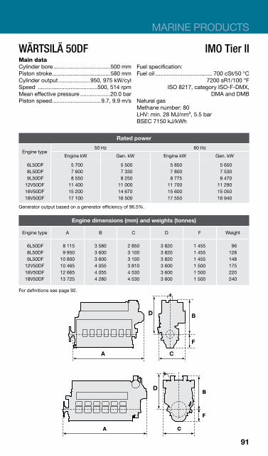
MARINE PRODUCTS
WÄRTSILÄ 50DF IMO Tier II Main data Cylinder bore ....................................500 mm Fuel specification: Piston stroke.....................................580 mm Fuel oil .................................... 700 cSt/50 °C Cylinder output.................... 950, 975 kW/cyl 7200 sR1/100 °F Speed ......................................500, 514 rpm ISO 8217, category ISO-F-DMX,Mean effective pressure ...................20.0 bar DMA and DMB Piston speed...............................9.7, 9.9 m/s Natural gas
Methane number: 80 LHV: min. 28 MJ/nm³, 5.5 bar BSEC 7150 kJ/kWh
Rated power
Engine type 50 Hz 60 Hz
Engine kW Gen. kW Engine kW Gen. kW
6L50DF 8L50DF 9L50DF 12V50DF 16V50DF 18V50DF
5 700 7 600 8 550
11 400 15 200 17 100
5 500 7 330 8 250
11 000 14 670 16 500
5 850 7 800 8 775
11 700 15 600 17 550
5 650 7 530 8 470
11 290 15 050 16 940
Generator output based on a generator efficiency of 96.5%.
Engine dimensions (mm) and weights (tonnes)
Engine type A B C D F Weight
6L50DF 8L50DF 9L50DF 12V50DF 16V50DF 18V50DF
8 115 9 950
10 800 10 465 12 665 13 725
3 580 3 600 3 600 4 055 4 055 4 280
2 850 3 100 3 100 3 810 4 530 4 530
3 820 3 820 3 820 3 600 3 600 3 600
1 455 1 455 1 455 1 500 1 500 1 500
96 128 148 175 220 240
For definitions see page 92.
91

DEFINITIONS AND NOTES FOR MEDIUM-SPEED ENGINES
ENGINE DIMENSIONS
A* Total length of the engine when the turbocharger is located at the flywheel end.
A Total length of the engine when the turbocharger is located at the free end.
B Height from the crankshaft centreline to the highest point.
B* Height from the crankshaft centreline to the highest point when the turbocharger is located at the flywheel end.
C Total width of the engine.
C* Total width of the engine when the turbocharger is located at the flywheel end.
D Minimum height from the crankshaft centreline when removing a piston.
F Distance from the crankshaft centreline to the bottom of the oil sump.
92
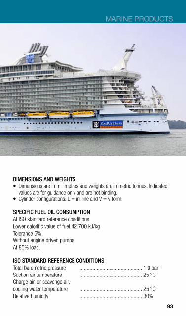
MARINE PRODUCTS
DIMENSIONS AND WEIGHTS z Dimensions are in millimetres and weights are in metric tonnes. Indicated
values are for guidance only and are not binding. z Cylinder configurations: L = in-line and V = v-form.
SPECIFIC FUEL OIL CONSUMPTION At ISO standard reference conditions Lower calorific value of fuel 42 700 kJ/kg Tolerance 5% Without engine driven pumps At 85% load.
ISO STANDARD REFERENCE CONDITIONS Total barometric pressure ............................................ 1.0 bar Suction air temperature ............................................ 25 °C Charge air, or scavenge air, cooling water temperature ............................................ 25 °C Relative humidity ............................................ 30%
93
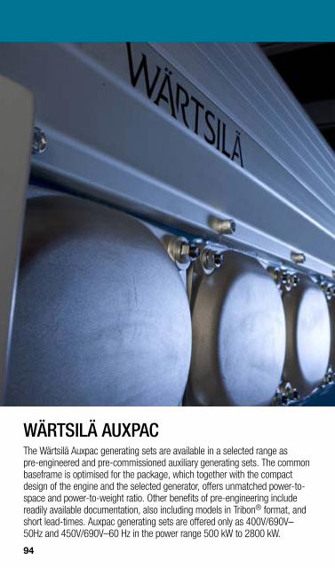
WÄRTSILÄ AUXPAC The Wärtsilä Auxpac generating sets are available in a selected range as pre-engineered and pre-commissioned auxiliary generating sets. The common baseframe is optimised for the package, which together with the compact design of the engine and the selected generator, offers unmatched power-tospace and power-to-weight ratio. Other benefits of pre-engineering include readily available documentation, also including models in Tribon® format, and short lead-times. Auxpac generating sets are offered only as 400V/690V– 50Hz and 450V/690V–60 Hz in the power range 500 kW to 2800 kW.
94

MARINE PRODUCTS
PRE-ENGINEERED MEDIUM-SPEED GENERATING SETS Main data of generators 60 Hz 50 Hz Voltage...........................................450, 690 V 400, 690 V Protection class.............................IP 23, IP 44 * IP 23, IP 44 * Temperature rise and isolation ......Class F Class F Cooling ..........................................Air, water * Air, water * * Option
Fuel oil specification: 700 cSt/50°C, 7200 sR1/100°F, ISO 8217, category ISO-F-RMK 55
60 Hz Output Dimensions (mm) and weights (tonnes)
Type kWe kVA A E L Weight
520W4L20 645W4L20 760W6L20 875W6L20 975W6L20 1050W6L20 1200W8L20 1400W8L20 1600W9L20 1800W6L26 2100W8L26 2400W8L26 2700W9L26
520 645 760 875 975
1 050 1 200 1 400 1 600 1 800 2 100 2 400 2 700
650 806 950
1 094 1 219 1 313 1 500 1 750 2 000 2 250 2 625 3 000 3 375
3 837 4 390 4 988 5 048 5 158 5 083 5 758 5 900 6 513 6 422 7 664 7 744 8 799
1 720 1 720 1 720 1 720 1 720 1 920 1 920 1 920 1 920 2 246 2 332 2 332 2 332
2 243 2 243 2 243 2 243 2 243 2 243 2 490 2 474 2 474 2 938 3 025 3 025 3 090
13.4 14.0 17.0 17.3 17.9 19.1 21.2 21.5 23.6 31.7 41.7 42.3 46.8
50 Hz Output Dimensions (mm) and weights (tonnes)
Type kWe kVA A E L Weight
520W4L20 670W4L20 790W6L20 860W6L20 1000W6L20 1140W6L20 1350W8L20 1550W9L20 1700W9L20 1950W6L26 2250W8L26 2550W9L26 2850W9L26
520 670 790 860
1 000 1 140 1 350 1 550 1 700 1 950 2 250 2 550 2 850
650 838 988
1 075 1 250 1 425 1 688 1 938 2 125 2 438 2 813 3 188 3 563
3 648 3 837 4 988 5 048 5 158 5 288 5 758 6 163 6 513 6 422 7 644 8 809 8 809
1 770 1 770 1 770 1 770 1 770 1 770 1 920 1 920 1 920 2 246 2 332 2 332 2 332
2 243 2 243 2 243 2 243 2 243 2 243 2 490 2 474 2 474 2 938 3 025 3 090 3 090
13.0 13.6 16.2 16.9 17.5 18.1 21.7 22.9 24.4 31.7 41.7 46.5 46.5
95

WÄRTSILÄ GENSETS A wide range of generating sets, comprising generator and diesel engine mounted on a common baseframe, are available for both service power generation and for diesel-electric propulsion. All generating sets listed in this section are based on medium-speed diesel engines designed for operating on heavy fuel oil. The generating sets are resiliently mounted and the generator voltage can be selected in all cases except for the Auxpac generating sets, which are Low Voltage only. Larger diesel generators are delivered for separate mounting of the diesel engine and generator.
POWER RANGE FOR WÄRTSILÄ GENSETS
Wärtsilä Genset 34DF
Wärtsilä Genset 32
Wärtsilä Genset 26
Wärtsilä Genset 20
Wärtsilä Genset 20DF
Wärtsilä Genset 38
kW 0 2000 4000 6000 8000 10,000 12,000
96

MARINE PRODUCTS
WÄRTSILÄ GENSET 20 IMO Tier II Main data Cylinder bore ....................................200 mm Piston stroke.....................................280 mm Cylinder output.................... 185, 200 kW/cyl Engine speed..........................900–1000 rpm Mean effective pressure ..........27.3, 28.0 bar Piston speed...............................8.4, 9.3 m/s Generator voltage....................... 0.4–13.8 kV Generator efficiency ...................... 0.95–0.96
Option: Common rail fuel injection.
Fuel oil specification: 700 cSt/50°C 7200 sR1/100°F ISO 8217, category ISO-F-RMK 700 SFOC 187 g/kWh at ISO condition
Rated power 60 Hz 50 Hz
Engine type 185 kW/cyl, 900 rpm 200 kW/cyl, 1000 rpm
Eng. kW Gen. kW Eng. kW Gen. kW
4L20
6L20
8L20
9L20
740
1 110
1 480
1 665
700
1 055
1 405
1 580
800
1 200
1 600
1 800
760
1 140
1 520
1 710
Dimensions (mm) and weights (tonnes) Engine type A* E* I* K L* Weight*
4L20
6L20
8L20
9L20
4 910
5 325
6 030
6 535
1770/1920
1770/1920/2070
1920/2070
2070/2300
990
895/975/1025
1025/1075
1075/1125
1 800
1 800
1 800
1 800
2338
2243/2323/2373
2474/2524
2524/2574
14.0
16.8
20.7
23.8
* Dependent on generator type and size. For definitions see page103.
97
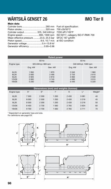
WÄRTSILÄ GENSET 26 IMO Tier II Main data Cylinder bore ....................................260 mm Piston stroke.....................................320 mm Cylinder output.................... 325, 340 kW/cyl Engine speed..........................900, 1000 rpm Mean effective pressure ..........23.0, 25.5 bar Piston speed.............................9.6, 10.7 m/s Generator voltage....................... 0.4–13.8 kV Generator efficiency ...................... 0.95–0.96
Fuel oil specification: 700 cSt/50°C 7200 sR1/100°F ISO 8217, category ISO-F-RMK 700 SFOC 187 g/kWh at ISO condition
Rated power
Engine type
60 Hz 50 Hz
325 kW/cyl, 900 rpm 340 kW/cyl, 1000 rpm
Eng. kW Gen. kW Eng. kW Gen. kW
6L26 8L26 9L26
12V26 16V26
1 950 2 600 2 925 3 900 5 200
1 870 2 495 2 810 3 745 4 990
2 040 2 720 3 060 4 080 5 440
1 960 2 610 2 940 3 915 5 220
Dimensions (mm) and weights (tonnes) Engine type A* E* I* K L* Weight*
6L26
8L26
9L26
12V26
16V26
7 500
8 000
8 500
8 400
9 700
2 300
2 300
2 300
2 700
2 700
1 200
1 200
1 200
1 560
1 560
2 430
2 430
2 430
2 765
2 765
3 081
3 219
3 219
3 634
3 711
40
45
50
60
70
* Dependent on generator type and size. For definitions see page103.
98

MARINE PRODUCTS
WÄRTSILÄ GENSET 32 Main data Cylinder bore ....................................320 mm Piston stroke.....................................400 mm Cylinder output....480, 500, 550, 580 kW/cyl Engine speed............................720, 750 rpm Mean effective pressure ..........24.9, 28.9 bar Piston speed.............................9.6, 10.0 m/s Generator voltage..................... 0.4 – 13.8 kV Generator efficiency .................... 0.95 – 0.97
Options: Common rail fuel injection, crude oil.
IMO Tier II Fuel oil specification: 700 cSt/50°C 7200 sR1/100°F ISO 8217, category ISO-F-RMK 700 SFOC 176 g/kWh at ISO condition
Rated power generating sets
Engine type
60 Hz/720 rpm 50 Hz/750 rpm
480 kW/cyl 550 kW/cyl 500 kW/cyl 580 kW/cyl
Engine kW Gen. kW Engine kW Gen.
kW Engine kW Gen. kW Engine kW Gen.
kW
6L32 7L32 8L32 9L32 12V32 16V32 18V32
2 880 3 360 3 840 4 320 5 760 7 680 8 640
2 760 3 230 3 690 4 150 5 530 7 370 8 290
3300 –
4400 4950 6600 8800
–
3170 –
4220 4750 6340 8450
–
3 000 3 500 4 000 4 500 6 000 8 000 9 000
2 880 3 360 3 840 4 320 5 760 7 680 8 640
3480 –
4640 5220 6960 9280
–
3340 –
4450 5010 6680 8910
–
Dimensions (mm) and weights (tonnes) Engine type A* E* I* K L* Weight*
6L32 7L32 8L32 9L32 12V32 16V32 18V32
8 345 9 215 9 755
10 475 10 075 11 175 11 825
2 290 2 690 2 690 2 890 3 060 3 060 3 360
1 450 1 650 1 630 1 630 1 700 1 850 1 850
2 345 2 345 2 345 2 345 2 120 2 120 2 120
3 940 4 140 3 925 3 925 4 365 4 280 4 280
57 69 77 84 96
121 133
* Dependent on generator type and size. Generator output based on a generator efficiency of 96%. Final measurements might differ depending on selected turbocharger execution. For definitions see page103.
99
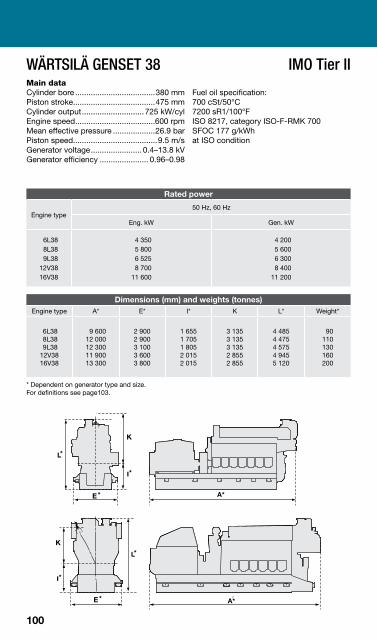
WÄRTSILÄ GENSET 38 IMO Tier II Main data Cylinder bore ....................................380 mm Piston stroke.....................................475 mm Cylinder output............................ 725 kW/cyl Engine speed....................................600 rpm Mean effective pressure ...................26.9 bar Piston speed......................................9.5 m/s Generator voltage....................... 0.4–13.8 kV Generator efficiency ...................... 0.96–0.98
Fuel oil specification: 700 cSt/50°C 7200 sR1/100°F ISO 8217, category ISO-F-RMK 700 SFOC 177 g/kWh at ISO condition
Rated power
Engine type 50 Hz, 60 Hz
Eng. kW Gen. kW
6L38 8L38 9L38
12V38 16V38
4 350 5 800 6 525 8 700
11 600
4 200 5 600 6 300 8 400
11 200
Dimensions (mm) and weights (tonnes) Engine type A* E* I* K L* Weight*
6L38 8L38 9L38 12V38 16V38
9 600 12 000 12 300 11 900 13 300
2 900 2 900 3 100 3 600 3 800
1 655 1 705 1 805 2 015 2 015
3 135 3 135 3 135 2 855 2 855
4 485 4 475 4 575 4 945 5 120
90 110 130 160 200
* Dependent on generator type and size. For definitions see page103.
100
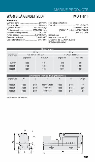
MARINE PRODUCTS
WÄRTSILÄ GENSET 20DF IMO Tier II Main data Cylinder bore ...................................200 mm Fuel oil specification: Piston stroke.....................................280 mm Fuel oil .................................... 700 cSt/50 °C Cylinder output.....................146/176 kW/cyl 7200 sR1/100 °F Engine speed........................ 1000/1200 rpm ISO 8217, category ISO-F-DMX,Mean effective pressure ...................20.0 bar DMA and DMB Piston speed..............................9.3/11.2 m/s Natural gas Generator voltage....................... 0.4–13.8 kV Methane number: 80 Generator efficiency ...................... 0.95–0.96 LHV: min. 28 MJ/Nm³, 5.5 bar
BSEC 8450 kJ/kWh
Rated power
Engine type
60 Hz 50 Hz
176 kW/cyl, 1200 rpm 146 kW/cyl, 1000 rpm
Engine kW Gen. kW Engine kW Gen. kW
6L20DF
8L20DF
9L20DF
1 056
1 408
1 584
1 014
1 352
1 521
876
1 168
1 314
841
1 121
1 261
Dimensions (mm) and weights (tonnes) Engine type A* E I* K L* Weight
6L20DF
8L20DF
9L20DF
5 325
6 030
6 535
2 070
2 070
2 300
900/980/1030
1030/1080
1080/1130
1 800
1 800
1 800
2 688
2 824
2 874
17
20.9
24
For definitions see page103.
101
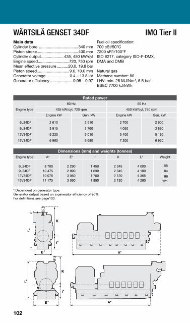
WÄRTSILÄ GENSET 34DF IMO Tier II Main data Cylinder bore ...................................340 mm Piston stroke.....................................400 mm Cylinder output.................... 435, 450 kW/cyl Engine speed............................720, 750 rpm Mean effective pressure ..........20.0, 19.8 bar Piston speed.............................9.6, 10.0 m/s Generator voltage..................... 0.4 – 13.8 kV Generator efficiency .................... 0.95 – 0.97
Fuel oil specification: 700 cSt/50°C 7200 sR1/100°F ISO 8217, category ISO-F-DMX, DMA and DMB
Natural gas Methane number: 80 LHV: min. 28 MJ/Nm³, 5.5 bar BSEC 7700 kJ/kWh
Rated power
Engine type
60 Hz 50 Hz
435 kW/cyl, 720 rpm 450 kW/cyl, 750 rpm
Engine kW Gen. kW Engine kW Gen. kW
6L34DF
9L34DF
12V34DF
16V34DF
2 610
3 915
5 220
6 960
2 510
3 760
5 010
6 680
2 700
4 050
5 400
7 200
2 600
3 890
5 190
6 920
Dimensions (mm) and weights (tonnes) Engine type A* E* I* K L* Weight
6L34DF 9L34DF
12V34DF 16V34DF
8 700 10 475 10 075 11 175
2 290 2 890 3 060 3 060
1 450 1 630 1 700 1 850
2 345 2 345 2 120 2 120
4 000 4 180 4 365 4 280
55
84
96 121
* Dependent on generator type. Generator output based on a generator efficiency of 96%. For definitions see page103.
102
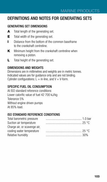
MARINE PRODUCTS
DEFINITIONS AND NOTES FOR GENERATING SETS
GENERATING SET DIMENSIONS
A Total length of the generating set.
E Total width of the generating set.
I Distance from the bottom of the common baseframe to the crankshaft centreline.
K Minimum height from the crankshaft centreline when removing a piston.
L Total height of the generating set.
DIMENSIONS AND WEIGHTS Dimensions are in millimetres and weights are in metric tonnes. Indicated values are for guidance only and are not binding. Cylinder configurations: L = in-line, and V = V-form.
SPECIFIC FUEL OIL CONSUMPTION At ISO standard reference conditions Lower calorific value of fuel 42 700 kJ/kg Tolerance 5% Without engine driven pumps At 85% load.
ISO STANDARD REFERENCE CONDITIONS Total barometric pressure ............................................ 1.0 bar Suction air temperature ............................................ 25 °C Charge air, or scavenge air, cooling water temperature ............................................ 25 °C Relative humidity ............................................ 30%
103
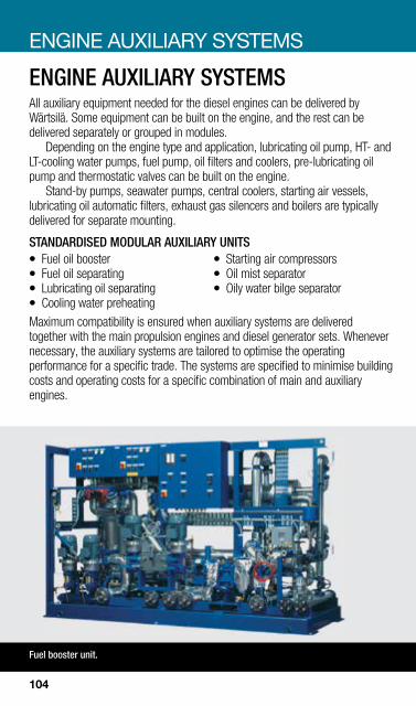
ENGINE AUXILIARY SYSTEMS
ENGINE AUXILIARY SYSTEMS All auxiliary equipment needed for the diesel engines can be delivered by Wärtsilä. Some equipment can be built on the engine, and the rest can be delivered separately or grouped in modules.
Depending on the engine type and application, lubricating oil pump, HT- and LT-cooling water pumps, fuel pump, oil filters and coolers, pre-lubricating oil pump and thermostatic valves can be built on the engine.
Stand-by pumps, seawater pumps, central coolers, starting air vessels, lubricating oil automatic filters, exhaust gas silencers and boilers are typically delivered for separate mounting.
STANDARDISED MODULAR AUXILIARY UNITS z Fuel oil booster z Starting air compressors z Fuel oil separating z Oil mist separator z Lubricating oil separating z Oily water bilge separator z Cooling water preheating Maximum compatibility is ensured when auxiliary systems are delivered together with the main propulsion engines and diesel generator sets. Whenever necessary, the auxiliary systems are tailored to optimise the operating performance for a specific trade. The systems are specified to minimise building costs and operating costs for a specific combination of main and auxiliary engines.
Fuel booster unit.
104
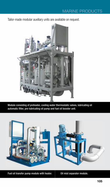
MARINE PRODUCTS
Tailor-made modular auxiliary units are available on request.
Fuel oil transfer pump module with heater. Oil mist separator module.
Module consisting of preheater, cooling water thermostatic valves, lubricating oil automatic filter, pre-lubricating oil pump and fuel oil booster unit.
105

WÄRTSILÄ REDUCTION GEARS – OUTPUT RANGE
0 5 10 15 20 25MW
142/140*
132*
116/118*
110/112*
105
95
85
75
68
62
56
50
46
42
38
Gear size
Single reduction gears – vertical offset SV, SCV
Single reduction gears – horizontal offset SH, SCH
128/125*
*Vertical offset only
WÄRTSILÄ REDUCTION GEARS The core function of a reduction gearbox is to reduce the main engine speed to the optimum propeller speed. The Wärtsilä gears have been designed to meet the highest standards of operational efficiency, reliability and low noise and vibration.
GEAR CONFIGURATIONS The gears can be supplied with built in multidisc clutches. Single input, single output gears are available with vertical or horizontal offsets of the shafts. Twin input single output gears can be delivered with up to 3.8 m horizontal offsets.
POWER TAKE-OFF (PTO) All Wärtsilä gears can be supplied with one or more PTOs for driving the shaft alternator, compressor or pump. For single vertical and horizontal gears, the standard PTO is primary driven. For twin input-single output gears the PTO is optionally primary or secondary driven. z A primary driven PTO is rotating whenever the engine is rotating. z A secondary driven PTO is rotating whenever the propeller shaft is rotating.
Two speed PTOs are available for gear types SCV85-SCV128.
106

MARINE PRODUCTS
Wärtsilä gear type TCH350-S58.
POWER TAKE-IN (PTI) Most Wärtsilä gears can be supplied with a combined PTO/PTI. In PTI mode the shaft alternator can also be used as an electric motor.
PTI is normally used for the following operation modes: z PTI “Booster” mode is used when the main power of the engine is too
small, in order to increase the total propulsion power. For this mode, no clutches are required on the gear.
z PTI “Take me home” mode is used in case of emergency, if the prime mover is out of operation. For this mode a minimum of 2 clutches are required on the gear. Two speed PTO/PTIs are available for gear types SCV85-SCV128.
INTEGRATED OR SEPARATE HYDRAULIC SYSTEM FOR GEAR AND CP PROPELLER Most Wärtsilä gears are purposely-designed with an integrated hydraulic system for both the gear and the CP propeller. As the separate hydraulic power unit for the CP propeller is superfluous, both installation costs for the yard and operational costs for the owner are reduced. For safety reasons the gear mechanically drives the main pump for the propeller. All gears can also be interfaced to a separate hydraulic power unit.
107

WÄRTSILÄ SINGLE INPUT REDUCTION GEARS WÄRTSILÄ VERTICAL OFFSET GEARS – DIMENSIONS SV/SCVsize A B
Std-Max C D E F G H J L N O SCV/SV
Weight tonnes*
SCV38 380 290 1305 115 465 1000 750 530 340 538 230 650 2.1
SCV42 420 320 1435 125 510 1500 830 585 530 558 255 715 2.7
SCV46 460 350 1570 140 560 1580 910 640 570 595 280 785 3.4
SCV50 500 380 1724 150 590 1340 1024 720 470 592 420 1035 4.2
SCV56 560 410 1848 160 645 1500 1110 800 530 650 450 1100 6.0
SCV62 620 440-470 2210 180 740 1580 1240 880 570 662 350 1150 7.0
SCV68 680 460-510 2370 200 800 1720 1360 960 625 720 370 1250 8.5
SCV75 750 480-530 2460 220 880 1850 1480 1040 660 800 450 1300/1095 10.0
SCV85 850 510-560 2720 250 1000 2100 1680 1178 730 915 550 1470/1220 14.5
SCV95 950 580-630 3025 280 1145 2350 1880 1327 800 1025 450 1640/1350 20.0
SCV105 1050 600 3328 250 1124 2628 2192 1668 1410 624 618 970 26.0
SV112 1120 600 3550 260 1198 2804 2272 1772 1500 660 655 800 29.0
SCV112 1120 700 3650 260 1198 2804 2272 1772 1500 660 595 1800 31.0
SV118 1180 600 3610 300 1190 2824 2268 1758 1520 716 655 827 32.0
SCV118 1180 700 3710 300 1190 2824 2268 1758 1520 716 595 1800 35.0
SV125 1250 600 3805 300 1325 2954 2396 1888 1600 808 635 860 35.0
SCV125 1250 700 3905 300 1325 2954 2396 1888 1600 808 595 1950 38.0
SV132 1320 600 3940 300 1390 3084 2516 2018 1630 850 665 875 38.0
SCV132 1320 700 4040 300 1390 3084 2516 2018 1630 850 610 2020 42.0
SV140 1400 600 4250 350 1500 3250 2600 2150 1700 900 720 920 44.0
SCV140 1400 700 4350 350 1500 3250 2600 2150 1700 900 680 2200 47.0
* Not binding
108
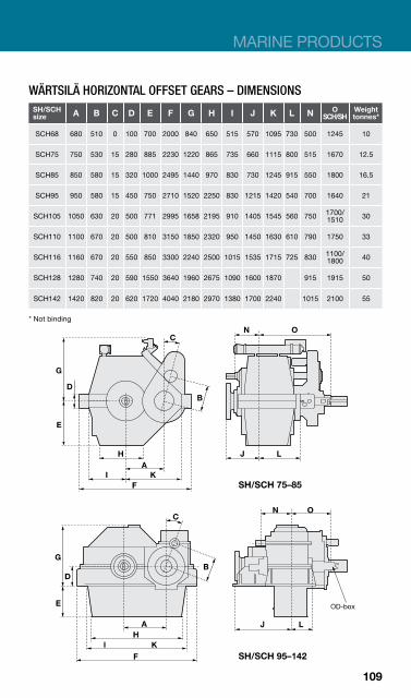
MARINE PRODUCTS
WÄRTSILÄ HORIZONTAL OFFSET GEARS – DIMENSIONS SH/SCH size A B C D E F G H I J K L N O
SCH/SH Weight tonnes*
SCH68 680 510 0 100 700 2000 840 650 515 570 1095 730 500 1245 10
SCH75 750 530 15 280 885 2230 1220 865 735 660 1115 800 515 1670 12.5
SCH85 850 580 15 320 1000 2495 1440 970 830 730 1245 915 550 1800 16.5
SCH95 950 580 15 450 750 2710 1520 2250 830 1215 1420 540 700 1640 21
SCH105 1050 630 20 500 771 2995 1658 2195 910 1405 1545 560 750 1700/ 1510 30
SCH110 1100 670 20 500 810 3150 1850 2320 950 1450 1630 610 790 1750 33
SCH116 1160 670 20 550 850 3300 2240 2500 1015 1535 1715 725 830 1100/ 1800 40
SCH128 1280 740 20 590 1550 3640 1960 2675 1090 1600 1870 915 1915 50
SCH142 1420 820 20 620 1720 4040 2180 2970 1380 1700 2240 1015 2100 55
* Not binding
109

Wärtsilä gear type TCH370-P63.
GEARS
WÄRTSILÄ TWIN INPUT-SINGLE OUTPUT REDUCTION GEARS DIMENSIONS
TCH size A B C D E F G J M N O Weight
tonnes*
TCH190 1900 460 10 320 980 2750 890 555 2300 360 995 15
TCH240 2400 490 20 450 1315 3580 1455 730 3135 570 1220 20
TCH250 2500 530 12.5 450 1400 3700 1150 800 3230 570 1290 28
TCH270 2700 580 10 500 1330 3900 1690 880 3410 600 1560 28
TCH310 3100 630 10 500 1550 4430 1400 880 3730 565 1570 34
TCH350 3500 580 10 700 1855 5370 1630 1270 4380 790 2140 50
TCH370 3700 630 10 700 1855 5565 1645 1270 4580 880 2140 60
TCH380 3800 730 10 760 2015 5800 1760 1380 4770 860 2300 70
* Not binding
110
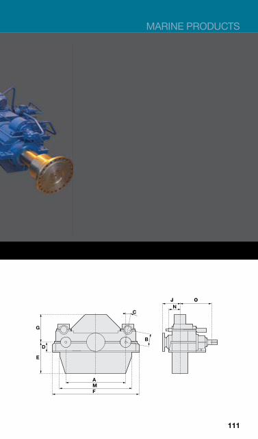
MARINE PRODUCTS
111

WÄRTSILÄ PROPELLERS WÄRTSILÄ CONTROLLABLE PITCH PROPELLERS Wärtsilä controllable pitch propellers offer excellent performance and manoeuvrability. For ships with frequent port calls, Wärtsilä CP propellers are the ideal choice for diesel mechanic propulsion, in combination with both medium-speed and low-speed diesel engines.
Full power is available in heavy and light conditions through automatic pitch adjustment. Engine overload is avoided in all conditions. CP propellers permit high skew angles to minimise noise and vibrations.The combinator curve can be shaped to avoid ship and machinery resonances, and to assure optimum operation of the complete propulsion system. z Compact, well proven, strong hub designs z Few components, robust design z Small overhang weight z Accurate stepless hydraulic pitch control z Reduced hydraulic power requirement z Easy to install, delivered as pre-assembled complete system z Under water replacement of blades
PROPELLER HUB RANGE FOR WÄRTSILÄ D-HUB
4D550
4D600
4D650
4D710
4D775
4D845
4D920
4D1000
4D1095
4D1190
4D1300
4D1415
4D1540
MW 0 2 4 6 8 10 12 14 16
112
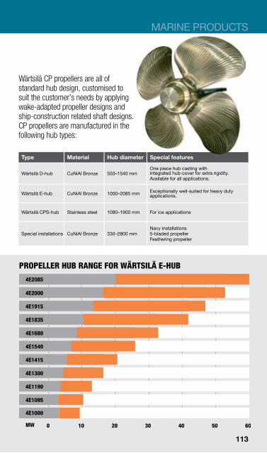
MARINE PRODUCTS
Wärtsilä CP propellers are all of standard hub design, customised to suit the customer’s needs by applying wake-adapted propeller designs and ship-construction related shaft designs. CP propellers are manufactured in the following hub types:
Type Material Hub diameter Special features
Wärtsilä D-hub CuNiAl Bronze 550–1540 mm One piece hub casting with integrated hub-cover for extra rigidity. Available for all applications.
Wärtsilä E-hub CuNiAl Bronze 1000–2085 mm Exceptionally well-suited for heavy duty applications.
Wärtsilä CPS-hub Stainless steel 1080–1900 mm For ice applications
Special installations CuNiAl Bronze 330–2800 mm Navy installations 5-bladed propeller Feathering propeller
PROPELLER HUB RANGE FOR WÄRTSILÄ E-HUB
4E2000
4E1915
4E1835
4E1680
4E1540
4E1415
4E1300
4E1190
4E1095
0 10 20 30 40 50 60 MW
4E2085
4E1000
113
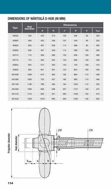
DIMENSIONS OF WÄRTSILÄ D-HUB (IN MM)
Type Hub diameter
Dimensions
a b c d e vmin
4D550 550 402 219 100 506 65 320
4D600 600 432 238 107 546 65 335
4D650 650 467 258 114 586 65 365
4D650 650 467 258 114 586 100 365
4D710 710 506 280 120 636 100 385
4D775 775 550 304 135 690 100 405
4D845 845 574 332 143 745 100 410
4D920 920 631 361 154 824 100 435
4D1000 1000 674 392 162 884 115 460
4D1095 1095 735 427 182 963 115 490
4D1190 1190 798 465 194 1052 115 525
4D1300 1300 859 508 207 1137 130 575
4D1415 1415 933 551 283 1229 130 610
4D1540 1540 1016 600 300 1332 130 655
114
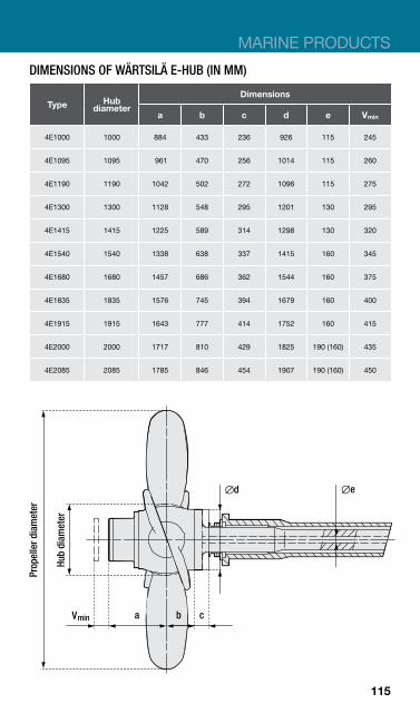
MARINE PRODUCTS
DIMENSIONS OF WÄRTSILÄ E-HUB (IN MM)
Type Hub diameter
Dimensions
a b c d e Vmin
4E1000 1000 884 433 236 926 115 245
4E1095 1095 961 470 256 1014 115 260
4E1190 1190 1042 502 272 1096 115 275
4E1300 1300 1128 548 295 1201 130 295
4E1415 1415 1225 589 314 1298 130 320
4E1540 1540 1338 638 337 1415 160 345
4E1680 1680 1457 686 362 1544 160 375
4E1835 1835 1576 745 394 1679 160 400
4E1915 1915 1643 777 414 1752 160 415
4E2000 2000 1717 810 429 1825 190 (160) 435
4E2085 2085 1785 846 454 1907 190 (160) 450
115

WÄRTSILÄ FIXED PITCH PROPELLERS Each ship’s hull has its own characteristics. In order to achieve the highest possible total efficiency of the vessel, the propeller must be a perfect match with the engine and the hull. A fixed pitch propeller is the choice when optimum efficiency, reliability and robustness are required. Fixed pitch propellers are usually installed for ocean sailing vessels, for example z Container vessels z Tankers z Bulk carriers z Dry cargo vessels Wärtsilä FP propellers for all ship types guarantee maximum efficiency and minimum noise and vibration levels due to tailor-made designs with the latest available technology.
MATERIAL Wärtsilä patented Cunial material provides excellent casting, machining and fatigue properties. An additional advantage is the good repairability.
116
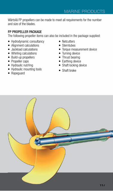
MARINE PRODUCTS
Wärtsilä FP propellers can be made to meet all requirements for the number and size of the blades.
FP PROPELLER PACKAGE The following propeller items can also be included in the package supplied: z Hydrodynamic consultancy z Netcutters z Alignment calculations z Sterntubes z Jackload calculations z Torque measurement device z Whirling calculations z Turning device z Build-up propellers z Thrust bearing z Propeller caps z Earthing device z Hydraulic nut/ring z Shaft locking device z Hydraulic mounting tools z Shaft brake z Ropeguard
3D model FPP package.
117

WÄRTSILÄ FIXED PITCH PROPELLERS FOR DIAMETERS 1000 TO 3500 MM Wärtsilä has developed complete propulsion systems based on fixed pitch propellers, for propeller diameters up to 3500 mm.
The most common ship types for this application are: z Luxury yachts z Government owned ships z Ships designed for inland waterways z Other special ships with diesel mechanic propulsion
For fixed pitch propulsion system the following characteristics apply: z Tailor-made propellers with 3, 4, 5, 6 and 7 blades in ISO class II, I and S
accuracy z Open propeller or propeller in 19A or Wärtsilä HR/HP nozzle z Shafting system complete with sterntube, seals and bearings
118
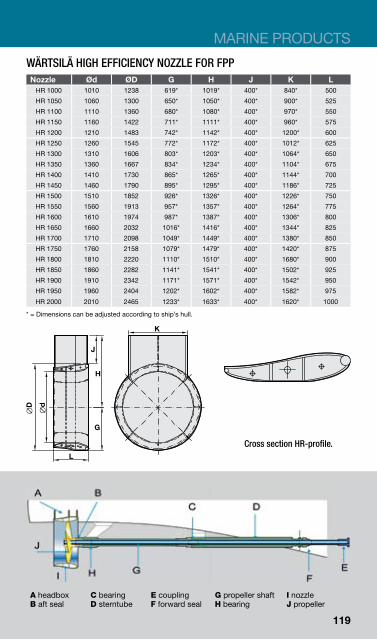
MARINE PRODUCTS
WÄRTSILÄ HIGH EFFICIENCY NOZZLE FOR FPP Nozzle Ød ØD G H J K L
HR 1000 1010 1238 619* 1019* 400* 840* 500
HR 1050 1060 1300 650* 1050* 400* 900* 525
HR 1100 1110 1360 680* 1080* 400* 970* 550
HR 1150 1160 1422 711* 1111* 400* 960* 575
HR 1200 1210 1483 742* 1142* 400* 1200* 600
HR 1250 1260 1545 772* 1172* 400* 1012* 625
HR 1300 1310 1606 803* 1203* 400* 1064* 650
HR 1350 1360 1667 834* 1234* 400* 1104* 675
HR 1400 1410 1730 865* 1265* 400* 1144* 700
HR 1450 1460 1790 895* 1295* 400* 1186* 725
HR 1500 1510 1852 926* 1326* 400* 1226* 750
HR 1550 1560 1913 957* 1357* 400* 1264* 775
HR 1600 1610 1974 987* 1387* 400* 1306* 800
HR 1650 1660 2032 1016* 1416* 400* 1344* 825
HR 1700 1710 2098 1049* 1449* 400* 1380* 850
HR 1750 1760 2158 1079* 1479* 400* 1420* 875
HR 1800 1810 2220 1110* 1510* 400* 1680* 900
HR 1850 1860 2282 1141* 1541* 400* 1502* 925
HR 1900 1910 2342 1171* 1571* 400* 1542* 950
HR 1950 1960 2404 1202* 1602* 400* 1582* 975
HR 2000 2010 2465 1233* 1633* 400* 1620* 1000
* = Dimensions can be adjusted according to ship’s hull.
Cross section HR-profile.
A headbox B aft seal
C bearing D sterntube
E coupling F forward seal
G propeller shaft H bearing
I nozzle J propeller
119

PROPULSORS
WÄRTSILÄ STEERABLE THRUSTERS With steerable thrusters thrust can be applied in any direction, resulting in superior manoeuvrability. Wärtsilä steerable thrusters are durable and reliable. z High thrust-to-power ratio z Modular flexible design or
compact standard design z Fixed pitch propeller or controllable
pitch propeller z With or without nozzle z Variable propeller diameter z Maintenance friendly z Low operating costs
WÄRTSILÄ COMPACT THRUSTERS z Easy mounting by welding z Robust design z High thrust-to-power ratio z Standardised Z- or L-drive design z Diesel or electric driven up to
3000 kW z Maintenance friendly z Optional mounting can
Wärtsilä modular thruster range:
WÄRTSILÄ MODULAR THRUSTERS z Flexible design, L-drive and
Z-drive z Various shaft arrangements z Diesel or electric driven up to
5500 kW z Optional mounting can available
WÄRTSILÄ RETRACTABLE THRUSTERS z L-drive and Z-drive z Retraction system with cylinders
or spindles z Electric driven up to 4500 kW
WÄRTSILÄ UNDERWATER DEMOUNTABLE THRUSTERS z L-drive and Z-drive z Stable three-wire handling z Electric driven up to 5500 kW
120

MARINE PRODUCTS
Wärtsilä compact thruster.
Wärtsilä containerised steerable thrusters.
Wärtsilä modular steerable thruster.
Wärtsilä underwater demountable steerable thrusters.
Wärtsilä retractable steerable thruster.
121
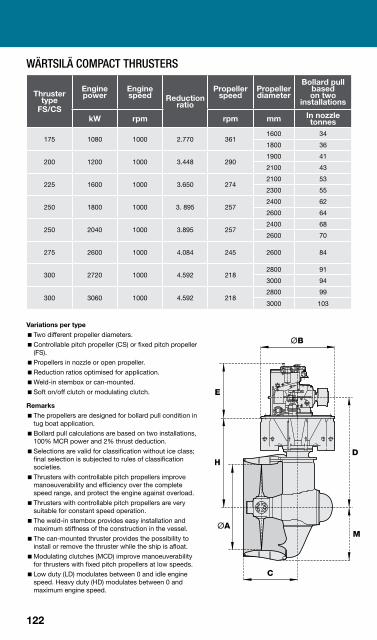
WÄRTSILÄ COMPACT THRUSTERS
Thruster type
FS/CS
Engine power
Enginespeed Reduction
ratio
Propeller speed
Propeller diameter
Bollard pull based on two
installations
kW rpm rpm mm In nozzle tonnes
175 1080 1000 2.770 361 1600 34
1800 36
200 1200 1000 3.448 290 1900 41
2100 43
225 1600 1000 3.650 274 2100 53
2300 55
250 1800 1000 3. 895 257 2400 62
2600 64
250 2040 1000 3.895 257 2400 68
2600 70
275 2600 1000 4.084 245 2600 84
300 2720 1000 4.592 218 2800 91
3000 94
300 3060 1000 4.592 218 2800 99
3000 103
Variations per type �Two different propeller diameters. �Controllable pitch propeller (CS) or fixed pitch propeller
(FS). �Propellers in nozzle or open propeller. �Reduction ratios optimised for application. �Weld-in stembox or can-mounted. �Soft on/off clutch or modulating clutch.
Remarks �The propellers are designed for bollard pull condition in
tug boat application. �Bollard pull calculations are based on two installations,
100% MCR power and 2% thrust deduction. �Selections are valid for classification without ice class;
final selection is subjected to rules of classification societies.
�Thrusters with controllable pitch propellers improve manoeuverability and efficiency over the complete speed range, and protect the engine against overload.
�Thrusters with controllable pitch propellers are very suitable for constant speed operation.
�The weld-in stembox provides easy installation and maximum stiffness of the construction in the vessel.
�The can-mounted thruster provides the possibility to install or remove the thruster while the ship is afloat.
�Modulating clutches (MCD) improve manoeuverability for thrusters with fixed pitch propellers at low speeds.
�Low duty (LD) modulates between 0 and idle engine speed. Heavy duty (HD) modulates between 0 and maximum engine speed.
122
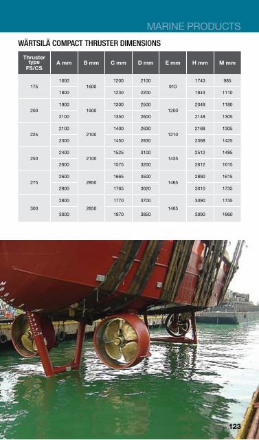
MARINE PRODUCTS
WÄRTSILÄ COMPACT THRUSTER DIMENSIONS
Thruster type
FS/CS A mm B mm C mm D mm E mm H mm M mm
175 1600
1600 1200 2100
910 1743 985
1800 1230 2200 1843 1110
200 1900
1900 1300 2500
1200 2048 1180
2100 1350 2600 2148 1305
225 2100
2100 1400 2630
1210 2168 1305
2300 1450 2830 2368 1425
250 2400
2100 1525 3100
1435 2512 1485
2600 1575 3200 2612 1615
275 2600
2850 1665 3500
1465 2890 1615
2800 1765 3620 3010 1735
300
2800
2850
1770 3700
1465
3090 1735
3000 1870 3850 3090 1860
123
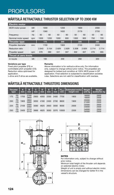
PROPULSORS WÄRTSILÄ RETRACTABLE THRUSTER SELECTION UP TO 2000 KW Electric motor MCR motor power kW 1000 1200 1600 2000
HP 1360 1632 2176 2720
Frequency Hz 50 60 50 60 50 60 50 60
Nominal motor speed rpm 1000 1200 1000 900 1000 900 750 720
175 200 225 250Thruster type Propeller diameter mm 1700 1900 2100 2400
Reduction ratio 2.643 3.154 2.929 2.929 3.308 2.929 2.714 2.714
Propeller speed rpm 378 380 341 307 302 307 276 265
Thrust at zero knots in nozzle kN 165 200 260 320
Variations per type Remarks Fixed pitch propeller (FS) or Above information is for vertical e-drive only. For information controllable pitch propeller (CS). only, subject to change without prior notice. The propellers are Reduction ratios optimised for designed for bollard pull condition at 100% MCR power in DP application. application. Final selection is subjected to classification societies L-drive and Z-drive are available. rules. Selections are not valid for classification with iceclass.
WÄRTSILÄ RETRACTABLE THRUSTERS DIMENSIONS
Thruster A B C D E F Estimated motor Weight Weight Hmin type mm mm mm mm mm mm mm height mm unit kg auxiliaries kg
175 FS CS 1700 2700
2850 2950 4050 2200 2400 7700 1850 18000 19000
2000 2500
200 FS CS 1900 2850
3000 3050 4160 2450 2700 8600 1900 20000 21000
2000 2500
225 FS CS 2100 3300
3450 3590 4625 2650 3000 9000 2000 22000 23000
2000 2500
250 FS CS 2400 3710
3710 3666 4625 3000 3370 10000 2200 34000 32000
2000 2500
NOTES For information only, subject to change without prior notice. Minimum total height of the thruster unit depends on selected electric motor. Weight of unit is empty and without electric motor. Dimensions can be changed for better fit in the vessel’s structure.
124
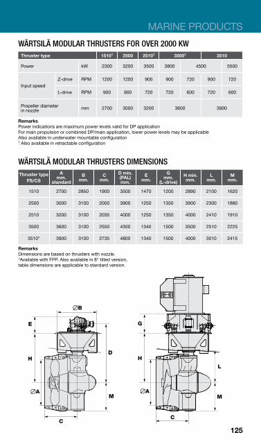
MARINE PRODUCTS
WÄRTSILÄ MODULAR THRUSTERS FOR OVER 2000 KW Thruster type 15101 2500 25101 35001 3510
Power kW 2300 3200 3500 3800 4500 5500
Z-drive RPM 1200 1200 900 900 720 900 720 Input speed
L-drive RPM 900 900 720 720 600 720 600
Propeller diameter in nozzle mm 2700 3000 3200 3600 3900
Remarks Power indications are maximum power levels valid for DP application For main propulsion or combined DP/main application, lower power levels may be applicable Also available in underwater mountable configuration 1 Also available in retractable configuration
WÄRTSILÄ MODULAR THRUSTERS DIMENSIONS A D min. G Thruster type B C E H min. L M mm. (PAL) mm. mm. mm. mm. mm. mm. mm.FS/CS standard mm. (L-drive)
1510 2700 2850 1900 3500 1470 1200 2890 2100 1620
2500 3000 3100 2000 3900 1250 1350 3900 2300 1880
2510 3200 3100 2035 4000 1250 1350 4000 2410 1910
3500 3600 3100 2550 4300 1340 1500 3500 2510 2225
3510* 3900 3100 2735 4800 1340 1500 4000 3010 2415
Remarks Dimensions are based on thrusters with nozzle. *Available with FPP. Also available in 8° tilted version, table dimensions are applicable to standard version.
125

WÄRTSILÄ TRANSVERSE THRUSTERS Bevel-gear driven propeller in a transverse tunnel. z Controllable or fixed pitch propeller z Maximum thrust with small diameter z Robust reliable design z Easy installation z Standard and demountable versions available z Applications for dynamic positioning and manoeuvring purposes
WÄRTSILÄ CT/FT 125-CT/FT 300 M TYPES
Type Electr. freq. Rational frequency Max. power (kW) 1 D L Mass2
(Hz) Input (rpm)
Output (rpm)
Manoeuvring
Dynamic positioning (mm) (mm) (kg)
CT/FT125 H 60 1755 519 614 404
1250 1550 2800 50 1465 433 516 341
CT/FT150 H 60 1755 430 880 589
1500 1800 4200 50 1465 359 735 492
CT/FT175 H 60 1755 379 1025 713
1750 2000 5900 50 1465 316 900 595
CT/FT175 M 60 1170 371 995 995
1750 1926 5600 50 975 309 829 829
CT/FT200 H 60 1170 263 1115 742
2000 2250 8100 50 1465 329 1394 928
CT/FT200 M 60 1170 324 1515 1227
2000 2181 7550 50 975 270 1262 1022
CT/FT225 H 60 1170 287 1785 1201
2250 2350 11500 50 975 239 1487 1001
CT/FT225 M 60 880 266 1649 1478
2250 2285 10600 50 975 295 1827 1502
CT/FT250 H 60 1170 265 2175 1458
2500 2550 13800 50 975 221 1813 1215
CT/FT250 M 60 880 233 1998 1599
2500 2482 12700 50 975 259 2213 1754
CT/FT275 H 60 880 216 2532 1735
2750 2800 17800 50 975 239 2805 1923
CT/FT275 M 60 880 238 2569 2241
2750 2704 15600 50 735 199 2145 1858
CT/FT300 H 60 880 216 3145 2454
3000 3000 22700 50 735 180 2625 2035
CT/FT300 M 60 705 210 3405 2657
3000 2916 22500 50 735 219 3550 2771
1) Max. power is dependent on sailing profile and classification society requirements. 2) Includes a standard tunnel with e-motor support.
126
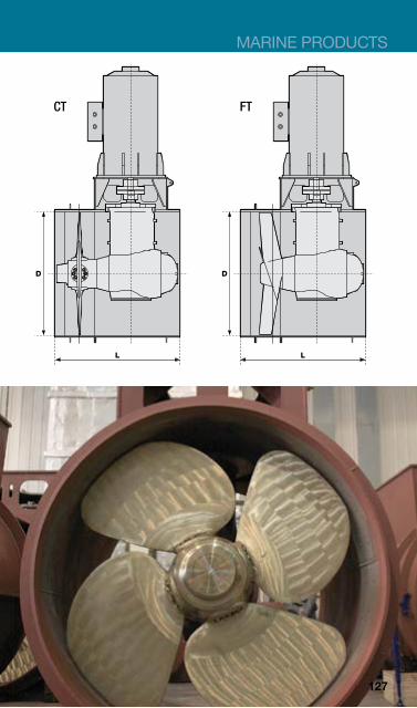
MARINE PRODUCTS
CT FT
127
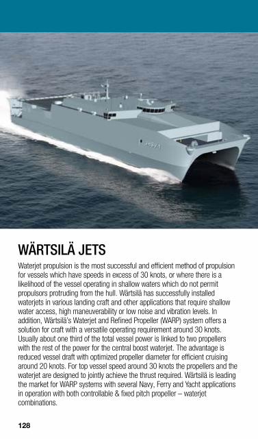
WÄRTSILÄ JETS Waterjet propulsion is the most successful and efficient method of propulsion for vessels which have speeds in excess of 30 knots, or where there is a likelihood of the vessel operating in shallow waters which do not permit propulsors protruding from the hull. Wärtsilä has successfully installed waterjets in various landing craft and other applications that require shallow water access, high maneuverability or low noise and vibration levels. In addition, Wärtsilä’s Waterjet and Refined Propeller (WARP) system offers a solution for craft with a versatile operating requirement around 30 knots. Usually about one third of the total vessel power is linked to two propellers with the rest of the power for the central boost waterjet. The advantage is reduced vessel draft with optimized propeller diameter for efficient cruising around 20 knots. For top vessel speed around 30 knots the propellers and the waterjet are designed to jointly achieve the thrust required. Wärtsilä is leading the market for WARP systems with several Navy, Ferry and Yacht applications in operation with both controllable & fixed pitch propeller – waterjet combinations.
128

MARINE PRODUCTS
WATERJET TYPES Wärtsilä has a unique portfolio of waterjet types available. The right waterjet for your application will be selected based on the operating profile and the required ship interface. The operating profile will determine the type of pump to be selected. For high power dense, high speed applications above 50 knots, a non-axial E-type pump design is available, delivering optimum performance for extreme vessels. For applications that require optimum propulsion efficiency for design speeds below 45–50 knots, our axial geometry waterjet designs are the optimised match. Our axial waterjet design is the most compact and most light weight waterjet design available in the full stainless high-end waterjet market, offering extra thrust at the low end of the speed range for top acceleration.
PRE-ASSEMBLED PACKAGES, WÄRTSILÄ SRF DESIGN For ease of installation with minimum ship interfaces, waterjet sizes up to the 810 can be delivered in an easy install package with all auxiliary systems pre-mounted. The waterjet inlet duct is included in the scope of supply with impeller shaft and bearings delivered pre-aligned on a ready-install skid.
The most compact, easy install waterjet package available in the market with stainless steel impeller and a unique stainless steel stator section for vessel top performance long after initial newbuild sea trials. Other system materials are optimised for use with light weight aluminium or composite crafts.
129
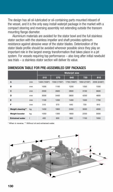
The design has all oil-lubricated or oil-containing parts mounted inboard of the vessel, and it is the only easy install waterjet package in the market with a compact steering and reversing assembly not extending outside the transom mounting flange diameter.
Aluminium materials are avoided for the stator bowl and the full stainless stator section with the stainless impeller and shaft provides optimum resistance against abrasive wear of the stator blades. Deterioration of the stator blade profile should be avoided wherever possible since they play an important role in the largest energy transformation that takes place in a jet system. For vessels requiring top performance – also long after initial newbuild sea trials – a stainless stator section will deliver its value.
DIMENSION TABLE FOR PRE-ASSEMBLED SRF PACKAGES Waterjet size
510 570 640 720 810
A mm 1400 (1500*) 1550 (1700*) 1750 (1900*) 1950 (2100*) 2200 (2400*)
B mm 1000 1100 1200 1350 1550
C mm 2300 2600 2800 3100 3600
D mm 3000 3400 3800 4200 4800
E mm 1100 1200 1400 1500 1700
F mm 510 570 640 720 810
Weight steering** kg 1450 1800 2450 3000 4000
Weight booster kg 1050 1300 1800 2250 3000
Entrained water l 400 600 800 1150 1650
* When in reverse. ** Without oil and entrained water.
A
C
D
E
F
B
130
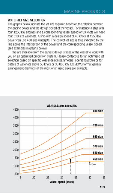
Engin
e pow
er (
BkW
)MARINE PRODUCTS
WATERJET SIZE SELECTION The graphs below indicate the jet size required based on the relation between the engine power and the design speed of the vessel. For instance a ship with four 1250 kW engines and a corresponding vessel speed of 33 knots will need four 510 size waterjets. A ship with a design speed of 40 knots at 1250 kW power can use 450 size waterjets. The correct jet size is thus indicated by the line above the intersection of the power and the corresponding vessel speed (see examples in graphs below).
We are available from the earliest design stages of the vessel to work with you on an optimised propulsion system. Please contact us for an optimised jet selection based on specific vessel design parameters, operating profile or for details of waterjets above 50 knots or 30 000 kW. DXF/DWG format general arrangement drawings of the most often used sizes are available.
WÄRTSILÄ 450–810 SIZES 4500
4000
3500
3000
2500
2000
1500 510 size
1000
500
450 size
510 size
570 size
640 size
720 size
810 size
450 size
15 20 25 30 35 40 Vessel speed (knots)
45
131

Engin
e pow
er (
BkW
)En
gin
e pow
er (
BkW
)
14 000
13 000
12 000
11 000
10 000
9000
8000
7000
6000
5000
4000
3000
2000 15
32 000
30 000
28 000
26 000
24 000
22 000
20 000
18 000
16 000
14 000
12 000
10 000
8000
6000
WÄRTSILÄ 910–1400 SIZES
910 size 1000 size
1100 size
1200 size
1300 size
1400 size
910 size
20 25 30 35 40 45
Vessel speed (knots)
WÄRTSILÄ 1500–2180 SIZES 2180 size
2020 size
1880 size
1720 size
1620 size 1500 size
15 20 25 30 35 40
Vessel speed (knots) 45
132

MARINE PRODUCTS
WÄRTSILÄ AXIAL JET SERIES, 6-BLADED WATERJETS GENERIC WEIGHTS AND DIMENSIONS FOR THE MOST OFTEN USED WATERJET SIZES
Inboard length Outboard length
Waterjet size
Outboard length mm
Inboard length mm 1)
Transom flange
Weight steering kg
Weight Booster kg
510 1300 2300 655 700 500
570 1450 2600 730 950 650
640 1650 2900 820 1200 850
720 1800 3200 920 1650 1150
810 2050 3600 1035 2250 1600
910 2300 4050 1165 3200 2250
1000 2500 4400 1280 4200 2900
1100 2800 4750 1405 5300 3700
1200 3000 5300 1535 7350 5300
1300 3250 5650 1665 8950 6250
1400 3500 6050 1790 11 100 7700
1500 3750 6550 1920 14 250 10 050
1620 4050 7000 2075 17 250 12 000
1720 4250 6800 2200 20 850 14 800
1880 4650 8050 2405 28 950 20 600
2020 5000 8550 2585 34 350 24 150
Note 1) Inboard length may vary depending on the optimised shape of the inlet duct.
133

Two Wärtsilä FP propellers in HR nozzles.
WÄRTSILÄ HIGH EFFICIENCY NOZZLE Fitting a nozzle increases the thrust at relatively low ship speeds. Significant savings can be achieved in terms of fuel consumption, depending on the number of revolutions and the capacity of the engine.
The improved Wärtsilä high efficiency nozzle, type HR and HP, combined with a Wärtsilä propeller, can produce up to 10% more thrust than conventional nozzles, both in bollard pull and in free sailing condition. The nozzle profile offers a double profiled cross section (outside and innerside). This sophisticated shape improves the water flow both into and out of the nozzle, increasing thrust performance.
ENERGOPAC Energopac is the optimised propulsion and manoeuvring solution for coastal and sea going vessels. The key objective is to reduce the vessel’s fuel consumption by integrating both propeller and rudder design. Each Energopac is designed to fit the vessel and to meet its specific requirements; this allows Energopac to be optimised fully for energy efficiency, whilst not compromising on either manoeuvrability or comfort levels. FUEL SAVINGS Energopac reduces fuel consumption because it reduces flow separation behind the propeller hub in an effective way. Extended studies show that for
134

MARINE PRODUCTS
the same course-keeping capabilities, Energopac will create less drag than conventional rudder systems.
Especially when using small – corrective – steering forces to keep your vessel on course, the difference in rudder resistance is significant. The high-lift performance of Energopac requires smaller steering angles and consequently reduces the rudder resistance.
DESIGN SPACE The application of Energopac gives more freedom to optimise between conflicting requirements. High performance propeller designs are often a compromise between increased efficiency and reduced vibration levels. Energopac allows for a propeller design, that gives the optimal balance between these requirements. TYPICAL APPLICATIONS Energopac will effectively reduce the operational costs for any vessel with a considerable share of free sailing time in its operational profile. Additionally, it will work very well for propellers with a relatively large propeller hub.
The potential savings are large for vessels with highly loaded controllable pitch propeller systems such as RoRo-vessels, ferries, container / multipurpose vessels and vessels with an ice class notation. COST SAVINGS WITH ENERGOPAC The reduction in fuel consumption depends very much on the vessel type, the operational profile of the vessel and also on the reference propeller and rudder. For any application, the power savings can be estimated by Wärtsilä. The estimate is based on the vessel design, operational profile and other requirements.
Proven savings in required power for a vessel’s trial speed vary between 2–9% with Energopac.
135

WÄRTSILÄ SEALS, BEARINGS, STERNTUBES & OTHERS Wärtsilä’s range of solutions is unequalled in the market. Reliable and efficient products are available for any type and for any size of vessel, for naval and for commercial applications.
The acquisition of Cedervall in 2011, one of the leading manufacturers of shaft seal and bearing systems for the marine industry, has further strengthened Wärtsilä’s leading position. WÄRTSILÄ SEALING SOLUTIONS Our comprehensive range of marine seals is designed for use in various propulsion applications covering both Commercial and Military vessels. Bespoke solutions can also be designed for special applications such as Tidal turbines or Industrial applications. WÄRTSILÄ BEARING SOLUTIONS Our comprehensive bearing portfolio includes traditional white-metal and latest generation composites for use with oil or water lubricated sterntube applications. Also including a range of Intermediate Shaft, Thrust and Generator Bearings. WÄRTSILÄ STERN TUBE SOLUTIONS Our products cover both oil or water lubricated systems and can be packaged in accordance with the customers specification. WÄRTSILÄ OTHER SEALS & BEARINGS PRODUCTS Wärtsilä water supply, filtration & temperature control systems. HYDRAULIC COUPLING NUTS AND BOLTS
136136
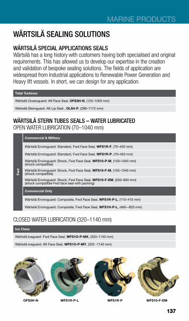
MARINE PRODUCTS
WÄRTSILÄ SEALING SOLUTIONS
WÄRTSILÄ SPECIAL APPLICATIONS SEALS Wärtsilä has a long history with customers having both specialised and original requirements. This has allowed us to develop our expertise in the creation and validation of bespoke sealing solutions. The fields of application are widespread from Industrial applications to Renewable Power Generation and Heavy lift vessels. In short, we can design for any application.
Tidal Turbines
Wärtsilä Oceanguard: Aft Face Seal, OFS3H-N, (125–1000 mm)
Wärtsilä Sternguard: Aft Lip Seal , OLS4-P, (286–1172 mm)
WÄRTSILÄ STERN TUBES SEALS – WATER LUBRICATED OPEN WATER LUBRICATION (70–1040 mm)
Fwd
Commercial & Military
Wärtsilä Enviroguard: Standard, Fwd Face Seal, WFS1R-F, (70–450 mm)
Wärtsilä Enviroguard: Standard, Fwd Face Seal, WFS1R-P, (70–450 mm)
Wärtsilä Enviroguard: Shock, Fwd Face Seal, WFS10-P-M, (150–1040 mm) (shock compatible)
Wärtsilä Enviroguard: Shock, Fwd Face Seal, WFS10-F-M, (150–1040 mm) (shock compatible)
Wärtsilä Enviroguard: Shock, Fwd Face Seal, WFS10-F-EM, (250–900 mm) (shock compatible Fwd face seal with packing)
Commercial Only
Wärtsilä Enviroguard: Composite, Fwd Face Seal, WFS1R-P-L, (110–410 mm)
Wärtsilä Enviroguard: Composite, Fwd Face Seal, WFS1H-P-L, (460–-820 mm)
CLOSED WATER LUBRICATION (320–1140 mm) Ice Class
Wärtsilä Iceguard: Fwd Face Seal, WFS1O-P-MX, (320–1140 mm)
Wärtsilä Iceguard: Aft Face Seal, WFS1O-P-MY, (320 -1140 mm)
OFS3H-N WFS1R-P-L WFS1R-P WFS10-F-EM
137137

WÄRTSILÄ STERN TUBES SEALS – OIL LUBRICATED STANDARD
Fwd
Inland Waterways & Coastal
Wärtsilä Sternguard: Fwd Face Seal, OFS1R-N-Z, (50–320 mm)
Wärtsilä Sternguard: Fwd Compact Lip Seal, OLS2-P-C, (136–362 mm)
Conventional Commercial
Wärtsilä Sternguard: Fwd Lip Seal, OLS2-P, (80–1172 mm)
Wärtsilä Sternguard: Fwd Face Seal, OFS1HW-F Seaqual, (205–1004 mm)
Wärtsilä Sternguard: Fwd Face Seal, OFS1HW-P Seaqual, (205–1004 mm)
Wärtsilä Sternguard: Fwd Face Seal, OFS1HW-N Seaqual, (66–1029 mm)
Special & Offshore
Wärtsilä Sternguard: Fwd Face Seal, OFS1HW-F Seaqual, (205–1004 mm)
Wärtsilä Sternguard: Fwd Face Seal, OFS1HW-P Seaqual, (205–1004 mm)
Wärtsilä Sternguard: Fwd Face Seal, OFS1HW-N Seaqual, (66–1029 mm)
Aft
Inland Waterways & Coastal
Wärtsilä Sternguard: Aft Face Seal, OFS1R-N, (50–320 mm)
Wärtsilä Sternguard: Aft Compact Lip Seal, OLS3-P-C, (136–362 mm)
Conventional Commercial
Wärtsilä Sternguard: Aft Lip Seal, OLS3-P, (80–1172 mm) Wärtsilä Sternguard: Aft Lip Seal, OLS4-P, (286–1172 mm) (extra redundancy-stand-by) Wärtsilä Sternguard: Aft Face Seal, OFS1H-F Seaqual, (205–1004 mm)
Wärtsilä Sternguard: Aft Face Seal, OFS1H-N Seaqual, (205–1004 mm)
Wärtsilä Sternguard: Aft Face Seal, OFS1H-P Seaqual, (205–1004 mm)
Special & Offshore
Wärtsilä Sternguard: Aft Face Seal, OFS1H-F Seaqual, (205–1004 mm)
Wärtsilä Sternguard: Aft Face Seal, OFS1H-N Seaqual, (205–1004 mm)
Wärtsilä Sternguard: Aft Face Seal, OFS1H-P Seaqual, (205–1004 mm)
OLS3-P
ANTI-POLLUTION
Aft
Merchant
Wärtsilä Airguard: Aft Lip Seal, OLS3A-P, (286–1172 mm)
Wärtsilä Airguard: Aft Lip Seal, OLS4A-P, (286–1172 mm) (extra redundancy)
ABRASION RESISTANT
Aft
Inland Waterways & Coastal
Wärtsilä Sternguard: Aft Face Seal, OFS1R-N-X, (50–320 mm)
Dredgers
Wärtsilä Sandguard: Aft Lip Seal, OLS3W-P, (286–1172 mm)
Wärtsilä Sandguard: Aft Lip Seal, OLS4W-P, (286–1172 mm) (extra redundancy) OFS1H-F-Seaqual
138 138

MARINE PRODUCTS
ABRASION RESISTANT & ANTI-POLLUTION
Aft
Cruise, Ferry & Offshore
Wärtsilä Oceanguard: Aft Face Seal, OFS3H-P, (400–760 mm)
Dredgers & Ocean Going
Wärtsilä Sandguard: Aft Lip Seal, OLS3AW-P, (286–1172 mm)
Wärtsilä Sandguard: Aft Lip Seal, OLS4AW-P, (286–1172 mm) (extra redundancy)
WÄRTSILÄ BULKHEAD SEALS STANDARD
Commercial & Military
Wärtsilä Floodguard: Standard Bulkhead Face seal, WFB1-F-M, (50–680 mm)
HIGH SPEED Commercial & Military
Wärtsilä Floodguard: High-Speed Bulkhead Face seal, WFB1-F-MS, (50–680 mm)
WÄRTSILÄ SUBMARINE SEALS SUBMARINE
Wärtsilä Diveguard: Single Barrier Fwd Face seal, WFS1H-P-M, (200–700 mm)
Wärtsilä Diveguard: Tandem Barrier Fwd Face seal, WFS2H-P-M, (200–700 mm)
WÄRTSILÄ WATERJETS SEALS WATERJETS
Commercial
Wärtsilä Jetguard: Standard, Waterjet Face Seal, WFS1R-P-J, (110–410 mm)
Wärtsilä Jetguard: Composite, Waterjet Face Seal, WFS1R-P-LJ, (110–410 mm)
Military
Wärtsilä Jetguard: Standard, Shock, Waterjet Face Seal, WFS1R-P-M, (120–380 mm) (shock compatible)
Wärtsilä Jetguard: Waterjet Face Seal, WFS1R-F-M, (120–380 mm) (shock compatible)
WATERJET HUBS Wärtsilä Hubguard: Compact, Face Seal, OFS1H-N-CJ, (50–300 mm) (oil lubricated waterjet hubs)
Wärtsilä Hubguard: Standard, Face Seal, OFS1H-NJ, (70–510 mm) (oil lubricated waterjet hubs)
WFB1-F-M WFS1H-P-M WFS1R-F-M WFS1R-P-LJ
139 139
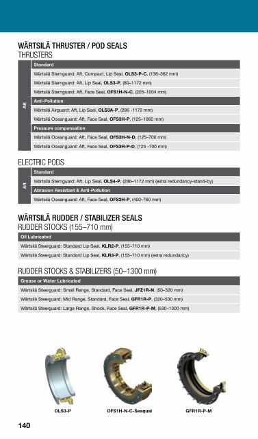
WÄRTSILÄ THRUSTER / POD SEALS THRUSTERS
Aft
Standard
Wärtsilä Sternguard: Aft, Compact, Lip Seal, OLS3-P-C, (136–362 mm)
Wärtsilä Sternguard: Aft, Lip Seal, OLS3-P, (80–1172 mm)
Wärtsilä Sternguard: Aft, Face Seal, OFS1H-N-C, (205–1004 mm)
Anti-Pollution
Wärtsilä Airguard: Aft, Lip Seal, OLS3A-P, (286 -1172 mm)
Wärtsilä Oceanguard: Aft, Face Seal, OFS3H-P, (125–1060 mm)
Pressure compensation
Wärtsilä Oceanguard: Aft, Face Seal, OFS3H-N-D, (125–700 mm)
Wärtsilä Oceanguard: Aft, Face Seal, OFS3H-P-D, (125 -700 mm)
ELECTRIC PODS
Aft
Standard
Wärtsilä Sternguard: Aft, Lip Seal, OLS4-P, (286–1172 mm) (extra redundancy-stand-by)
Abrasion Resistant & Anti-Pollution
Wärtsilä Oceanguard: Aft, Face Seal, OFS3H-P, (400–760 mm)
WÄRTSILÄ RUDDER / STABILIZER SEALS RUDDER STOCKS (155–710 mm)
Oil Lubricated
Wärtsilä Steerguard: Standard Lip Seal, KLR2-P, (155–710 mm)
Wärtsilä Steerguard: Standard Lip Seal, KLR3-P, (155–710 mm) (extra redundancy)
RUDDER STOCKS & STABILIZERS (50–1300 mm) Grease or Water Lubricated
Wärtsilä Steerguard: Small Range, Standard, Face Seal, JFZ1R-N, (50–320 mm)
Wärtsilä Steerguard: Mid Range, Standard, Face Seal, GFR1R-P, (320–530 mm)
Wärtsilä Steerguard: Large Range, Shock, Face Seal, GFR1R-P-M, (530–1300 mm)
OLS3-P OFS1H-N-C-Seaqual GFR1R-P-M
140
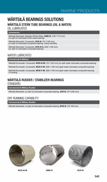
MARINE PRODUCTS
WÄRTSILÄ BEARINGS SOLUTIONS WÄRTSILÄ STERN TUBE BEARINGS (OIL & WATER) OIL LUBRICATED
Commercial
Wärtsilä Sternsafe: Standard White Metal, OMS-N, (136–1172 mm) (un-split oil lubricated white metal bearing)
Wärtsilä Sternsafe: Composite, OCS-N, (70–1100 mm) (un-split oil lubricated composite bearing, mainly retrofits)
Wärtsilä Sternsafe: Composite, OCS-N-X, (200–1100 mm) (un-split oil lubricated composite bearing)
WATER LUBRICATED Commercial & Military
Wärtsilä Envirosafe: Composite, WCS-N-M, (70–1100 mm) (un-split water lubricated composite bearing)
Wärtsilä Envirosafe: Composite, WCS-P-M, (200–1100 mm) (split water lubricated composite bearing)
Wärtsilä Envirosafe: Composite, WCS-F-M, (300–1100 mm) (split water lubricated composite bearing) O housing
WÄRTSILÄ RUDDER / STABILIZER BEARINGS STANDARD
Commercial & Military Rudder
Wärtsilä Steersafe: un-split oil lubricated composite bearing, JCR-N, (70–1200 mm)
DRY RUNNING CAPABILITY Commercial & Military Rudder
Wärtsilä Steersafe: un-split oil lubricated composite bearing, DCR-N, (70–705 mm)
WCS-N-M OMS-N DCR-N
141
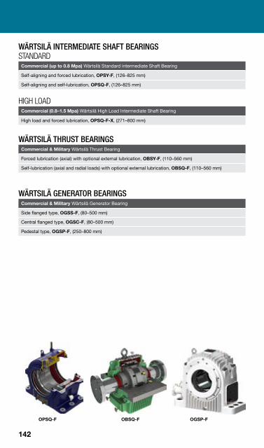
WÄRTSILÄ INTERMEDIATE SHAFT BEARINGS STANDARD
Commercial (up to 0.8 Mpa) Wärtsilä Standard intermediate Shaft Bearing
Self-aligning and forced lubrication, OPSY-F, (126–825 mm)
Self-aligning and self-lubrication, OPSQ-F, (126–825 mm)
HIGH LOAD Commercial (0.8–1.5 Mpa) Wärtsilä High Load Intermediate Shaft Bearing
High load and forced lubrication, OPSQ-F-X, (271–800 mm)
WÄRTSILÄ THRUST BEARINGS Commercial & Military Wärtsilä Thrust Bearing
Forced lubrication (axial) with optional external lubrication, OBSY-F, (110–560 mm)
Self-lubrication (axial and radial loads) with optional external lubrication, OBSQ-F, (110–560 mm)
WÄRTSILÄ GENERATOR BEARINGS Commercial & Military Wärtsilä Generator Bearing
Side flanged type, OGSS-F, (80–500 mm)
Central flanged type, OGSC-F, (80–500 mm)
Pedestal type, OGSP-F, (250–800 mm)
OPSQ-F OBSQ-F OGSP-F
142

MARINE PRODUCTS
WÄRTSILÄ STERN TUBES SOLUTIONS All packages designed against standards and bespoke requirements to suit each application. Options include oil lubricated sterntubes with white metal or composite bearings or water lubricated sterntube with composite bearings.
OT-M OT
WÄRTSILÄ OTHER SEALS & BEARINGS PRODUCTS
WÄRTSILÄ WATER QUALITY SYSTEMS Pumped water flush supply systems with various filtration and temperature control options to improve & increase life of the seal and bearing products installed. Systems are adapted to suit applications either by filtering to required standards in silty/ gritty water environments or controlling closed water temperature in ice-class type applications. Suitable for both open and closed water lubricated sterntubes.
WYS-M
WATER QUALITY SYSTEMS Flush Supply & Filtration
Wärtsilä Water Quality System: open water (clear), WYS-M
Wärtsilä Water Quality System: open water (high performance- silty), WYS-MX
Flush Supply, Filtration & Temperature Control
Wärtsilä Water Quality System: closed water system, WQS-M
143
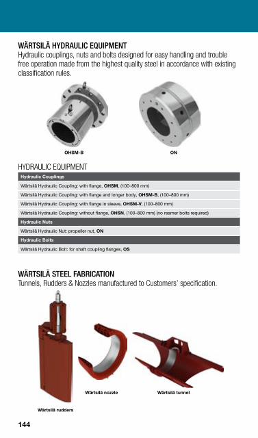
WÄRTSILÄ HYDRAULIC EQUIPMENT Hydraulic couplings, nuts and bolts designed for easy handling and trouble free operation made from the highest quality steel in accordance with existing classification rules.
OHSM-B ON
HYDRAULIC EQUIPMENT Hydraulic Couplings
Wärtsilä Hydraulic Coupling: with flange, OHSM, (100–800 mm)
Wärtsilä Hydraulic Coupling: with flange and longer body, OHSM-B, (100–800 mm)
Wärtsilä Hydraulic Coupling: with flange in sleeve, OHSM-V, (100–800 mm)
Wärtsilä Hydraulic Coupling: without flange, OHSN, (100–800 mm) (no reamer bolts required)
Hydraulic Nuts
Wärtsilä Hydraulic Nut: propeller nut, ON
Hydraulic Bolts
Wärtsilä Hydraulic Bolt: for shaft coupling flanges, OS
WÄRTSILÄ STEEL FABRICATION Tunnels, Rudders & Nozzles manufactured to Customers’ specification.
Wärtsilä nozzle Wärtsilä tunnel
Wärtsilä rudders
144

MARINE PRODUCTS
All our products can be described with an acronym:
W F S 1 O - P - M * * * Example of
LUBRICATION: W = WATER
PRODUCT TYPE: F = FACE SEAL
POSITION: S = SHAFT
NO. OF SEALING INTERFACES: 1
SEAL SPRING TYPE OR BASIC F : O = OMEGA SPRINGS
SERVICEABILITY: P = SERVICEABLE WITH SHAFT IN-SITU
ADDITIONAL FEATURES: M = SHOCK COMPATIBLE
W
F
S
1
O -
P
-
M
*
*
*
SEAL SPRING TYPE OR BASIC FUNCTION (seals, line/shaft/thrust/generator bearings only) A H O Q R W Y AW M N C S P
Air flush Helical spring Omega spring Self oil lubrication Rubber bellows/body Water flush Forced oil lubrication Air and water flush Flange mounted No flange Central flange Side flanged Pedestal
= = = = = = = = = = = = =
ADDITIONAL FEATURES (if applicable) C D E L M S X Y Z B V J
Compact Damper/lip system Emergency packing Lightweight composite Shock compatible High speed High performance Outboard water Inboard oil Longer body Flange in sleeve Jet version
= = = = = = = = = = = =
SERVICEABILITY (if applicable) F
N P
Replaceable and serviceable with shaft in-situ Non serviceable in-situ Serviceable with shaft in-situ
=
= =
POSITION (if applicable) B R S Z
Bulkhead Rudder Shaft Stabilizer or rudder
= = = =
LUBRICATION (internal operating) D G J K O W
Dry, grease, oil or water Grease or water Grease, oil or water Grease or oil Oil Water
= = = = = =
PRODUCT TYPE C F L M P Y
Q
T H N S B G
Composite bearing Face seal Lip seal White metal bearing Line shaft/plummer bearing Flush supply & filtration system Flush supply, filtration & temperature control Stern tube Hydraulic coupling Hydraulic nut Hydraulic bolt Thrust bearing Generator bearing
= = = = = =
=
= = = = = =
NO. OF SEALING INTERFACES (seals only) OR COMPOSITE BEARING MATERIAL DESIGNATION Sealing interfaces: 1, 2, 3 or 4 (as applicable) Bearing material: 01, 02, 03 etc. (as applicable)
WÄRTSILÄ SEALS AND BEARINGS DESCRIPTVE PRODUCT NAMES (WFS1O-P-M***)
145

146
WÄRTSILÄ HAMWORTHY FLARE GAS RECOVERY The Wärtsilä Hamworthy technology safely captures and handles flare gas, which can then be re-utilised for other purposes.
Flaring gas emits some 400 million tons of CO2 annually to the atmosphere, and has a notable impact on the environment. Our Flare Gas Recovery System offers a substantial reduction in such emissions. It allows the previously flared gas to be available for re-utilisation as fuel or export gas re-injected, as feed for boilers, and for many other gas related applications.
The closing of the flare line during normal operations results in significantly decreased flare tip wear, allowing it to typically last for the lifetime of the field. The concept comprises flare header isolation equipment, a gas recovery system, and a reliable flare gas ignition system.
Our systems can be designed to meet the specific process conditions of the plant.
146

147
WÄRTSILÄ HAMWORTHY FLARE GAS IGNITION Our Flare Gas Ignition System ensures the safe and reliable ignition of the flare whenever required.
The Wärtsilä Hamworthy system is suitable for all flare tips and may ignite several flares on a single flare deck. It is installed at a safe distance from the flare stack, with a guide pipe leading to the flare tip. The system combines high reliability and availability over the lifetime of the facility with low maintenance requirements, and is easily retrofitted into existing installations.
Pilot burners are not necessary, and there is no heat sensitive equipment, such as cables, instrumentation and electrodes, on the flare deck.
WÄRTSILÄ HAMWORTHY HYDROCARBON VENT GAS (VOC) RECOVERY Our VOC Recovery system for Hydrocarbon Gas is based on the principle of condensation. This allows organic components in the vent gas to be separated and returned to their place of origin, or used as valuable and clean fuel for both increased product output and environmental benefits.
When used in combination with a power generation system, emissions of VOC are totally eliminated. The system thus becomes a net provider of steam or electric power during operation by utilizing the lightest non condensable fractions of VOC as fuel. The plant operates on electric power and a cooling source, such as water or air. The compact modular design, which is assembled and tested prior to delivery, ensures fast and easy installation.
FUEL FLEXIBILITY
147
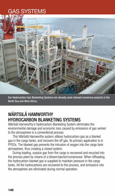
Our Hydrocarbon Gas Blanketing Systems are already used onboard numerous projects in the North Sea and West Africa.
GAS SYSTEMS
WÄRTSILÄ HAMWORTHY HYDROCARBON BLANKETING SYSTEMS Wärtsilä Hamworthy’s Hydrocarbon Blanketing System eliminates the environmental damage and economic loss caused by emissions of gas vented to the atmosphere in a conventional process
This Wärtsilä Hamworthy system utilises hydrocarbon gas as a blanket gas in the cargo tanks, and recovers the off gas. Its primary application is in FPSOs. The blanket gas prevents the intrusion of oxygen into the cargo tank atmosphere, thus creating a closed system.
During loading, surplus gas from the cargo is recovered and recycled into the process plant by means of a blower/ejector/compressor. When offloading, the hydrocarbon blanket gas is supplied to maintain pressure in the cargo tanks. All the hydrocarbons are recovered to the process, and emissions into the atmosphere are eliminated during normal operation.
148

FUEL FLEXIBILITY
The first VOC condensation system with zero emissions was installed on the shuttle tanker Stena Alexita, operated by ExxonMobil in the North Sea oil fields.
WÄRTSILÄ HAMWORTHY VOC RECOVERY Our field proven VOC recovery system is self supplied with energy and results in zero VOC emissions.
Volatile Organic Compound (VOC) emissions from the global sea transportation of crude oil and associated products, account for a total of more than 5 million tons per year. The Wärtsilä Hamworthy VOC plant ensures that cargo tank pressures are maintained low enough to keep the vent valve closed. This prevents VOC from being emitted to the atmosphere, and the gas is instead fed to the VOC recovery module, where it is treated by compression and condensation. The liquefied gas is then fed to the VOC fuel tank.
We have also developed a for VOC recovery in offshore oil loading applications. It exceeds the Norwegian authorities’ requirements for NMVOCs by reducing VOC emissions by 100 per cent, including methane, which is not currently specified in the regulatory requirements.
149
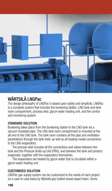
WÄRTSILÄ LNGPac The design philosophy of LNGPac is based upon safety and simplicity. LNGPac is a complete system that includes the bunkering station, LNG tank and tank room compartment, process skid, glycol-water heating unit, and the control and monitoring system.
STANDARD SOLUTION Bunkering takes place from the bunkering station to the LNG tank via a vacuum insulated pipe. The LNG tank room compartment is mounted at the aft end of the LNG tank. The tank room contains all the pipe and ventilation penetrations through the tank shell, as well as all heating media connections to the LNG evaporators.
The process skid includes all the connections and valves between the tank and the Pressure Build-up Unit (PBU), and between the tank and product evaporator, together with the evaporators themselves.
The evaporators are heated by glycol-water that is circulated within a glycol-water heating unit.
CUSTOMISED SOLUTION LNGPac gas supply system can be customized to the needs of each project on a case to case basis by Wärtsilä gas fuelled vessel expert team. Some
150
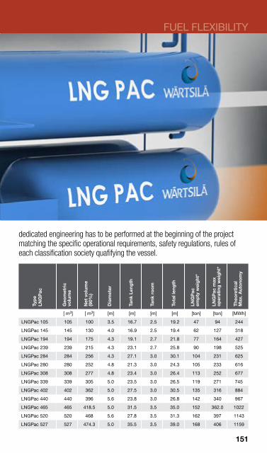
FUEL FLEXIBILITY
dedicated engineering has to be performed at the beginning of the project matching the specific operational requirements, safety regulations, rules of each classification society quafifying the vessel.
Typ
e LN
GP
ac
Geo
met
ric
volu
me
Net
vo
lum
e(9
0%)
Dia
met
er
Tank
Len
gth
Tank
ro
om
Tota
l len
gth
LNG
Pac
em
pty
wei
ght
*
LNG
Pac
max
o
per
atin
g w
eig
ht*
The
ore
tical
M
ax. A
uto
nom
y
[ m3] [ m3] [m] [m] [m] [m] [ton] [ton] [MWh]
LNGPac 105 105 100 3.5 16.7 2.5 19.2 47 94 244
LNGPac 145 145 130 4.0 16.9 2.5 19.4 62 127 318
LNGPac 194 194 175 4.3 19.1 2.7 21.8 77 164 427
LNGPac 239 239 215 4.3 23.1 2.7 25.8 90 198 525
LNGPac 284 284 256 4.3 27.1 3.0 30.1 104 231 625
LNGPac 280 280 252 4.8 21.3 3.0 24.3 105 233 616
LNGPac 308 308 277 4.8 23.4 3.0 26.4 113 252 677
LNGPac 339 339 305 5.0 23.5 3.0 26.5 119 271 745
LNGPac 402 402 362 5.0 27.5 3.0 30.5 135 316 884
LNGPac 440 440 396 5.6 23.8 3.0 26.8 142 340 967
LNGPac 465 465 418.5 5.0 31.5 3.5 35.0 152 362.0 1022
LNGPac 520 520 468 5.6 27.8 3.5 31.3 162 397 1143
LNGPac 527 527 474.3 5.0 35.5 3.5 39.0 168 406 1159
151

WÄRTSILÄ HAMWORTHY LNG FUEL SYSTEMS Wärtsilä Oil & Gas Systems (formerly Hamworthy Oil & Gas Systems) can deliver LNG fuel gas systems for propulsion and power generation for any applicable types of ship or engine, both low pressure and high pressure.
Our LNG fuel gas systems are typically delivered as complete skids, ready for shipboard installation. The skids comprise all equipment and systems for LNG storage, evaporation, heating, and pressure control. Each skid normally has the capacity to supply either 50% or 100% of the gas engine’s requirement, and will supply natural gas at the required pressure and temperature to the engine’s gas regulation unit.
We work closely with our customers to develop technological solutions that meet their needs for increased fuel flexibility, energy efficiency and environmental performance in today’s fast changing LNG markets.
152
Our LNG production facility in Snurrevarden, Norway was the first freestanding small scale LNG plant in Northern Europe. It is fully automated with remote monitoring and control capabilities.
Since then we have delivered a number of complete onshore LNG production facilities, including the introduction of an improved liquefaction system with double expanders based on the reversed Brayton cycle.
The LNG production plant for Gasum in Finland, delivered in 2010, uses surplus liquid nitrogen (LIN) for the LNG generation and incorporates new technology that reduces LIN consumption by 50%.
Wärtsilä Hamworthy will deliver a biogas liquefaction plant to the Municipality of Oslo during spring 2013.
WÄRTSILÄ HAMWORTHY LNG LIQUEFACTION Our industry leading natural gas liquefaction solutions combine high energy efficiency and plant reliability with operational robustness, flexibility, and ease of operation.
Wärtsilä Hamworthy’s innovative LNG production plant solutions suitable for small to medium size liquefaction capacities, are based on well proven equipment and process control principles.
Wärtsilä Hamworthy has also developed the energy efficient NewMR liquefaction technology for even lower capacities than our usual small and mid-scale LNG plants. For production capacities below 50 tonnes per day, the NewMR technology uses a mixed refrigerant in combination with standard equipment to achieve low investment costs and fast manufacture of the liquefaction unit. In the growing liquid biogas fuel market, this technology adds to the value chain.
FUEL FLEXIBILITY
153

WÄRTSILÄ HAMWORTHY LNG REGASIFICATION Our portfolio of LNG regasification technologies represents an industry benchmark in terms of energy efficiency, robustness, and operational flexibility. It is available either as multi-skid deliveries, or as complete turnkey and singlelift topside modules.
We have delivered and put into operation numerous floating LNG regasification plants based on either closed loop regasification technology, using steam with water/glycol as the intermediate heating medium, or open loop regasification technology using sea water with propane as the intermediate heating medium. We have also delivered modularized regasification plants for jetty installations. These facilitate a much shorter construction time compared to the traditional land based LNG regasification terminal project.
154

WÄRTSILÄ HAMWORTHY LNG RELIQUEFACTION Wärtsilä Oil & Gas Systems is an established leading designer, developer, and supplier of energy efficient LNG Boil-Off Gas (BOG) reliquefaction plants that are reliable, safe, robust and flexible.
Wärtsilä has by far the highest number of BOG reliquefaction plants installed in the global LNG carrier fleet. They offer owners and operators unsurpassed lifecycle efficiency, and are backed by a full range of complementary services, including operation & maintenance training, remote monitoring & diagnostics, and customized service and support agreements.
Wärtsilä Oil & Gas Systems has commercialised and improved the reliquefaction technology since it was originally patented by Kværner and licensed by Hamworthy in the late 1990s. Our boil-off gas (BOG) reliquefaction plants have been installed on numerous vessels, including the entire Q-Flex fleet of 216,000 m3 LNG carriers. The 31 Wärtsilä Hamworthy LNG BOG reliquefaction plants delivered to the Q-Flex fleet are installed on ships driven by slow speed diesel propulsion engines. The process is based on the reversed nitrogen Brayton cycle refrigeration technology, combined with a process solution for separating nitrogen from the BOG. We have also delivered the same type of systems to a number of LNG carriers with dual-fuel diesel electric (DFDE) propulsion. The liquefaction of BOG on LNG carriers results in increased cargo deliveries, and allows owners and operators to choose the most optimal propulsion system and operating profile.
We work closely with our customers to develop technological solutions that meet their needs for increased fuel flexibility, energy efficiency, and environmental performance in today’s fast changing LNG market.
FUEL FLEXIBILITY
155

WÄRTSILÄ HAMWORTHY LPG & ETHYLENE CARGO HANDLING Our reliable and innovative LPG & Ethylene cargo handling technology is vital for gas carriers and includes reliquefaction plants.
For LPG and Ethylene carriers we offer services including engineering of complete cargo handling systems, tank design and supply cargo handling equipment such as reliquefaction and cooling systems for liquid gas, inert gas plants and nitrogen generator systems, deepwell and booster pumps. All equipment is designed and engineered in-house.
We have recently developed newly patented cargo handling reliquefaction technology conferring to a number of operational and cost benefits for owners. The system has been developed for larger LPG carriers, typically ships above 60,000 m3, aimed to reduce installation, operation and maintenance costs.
156
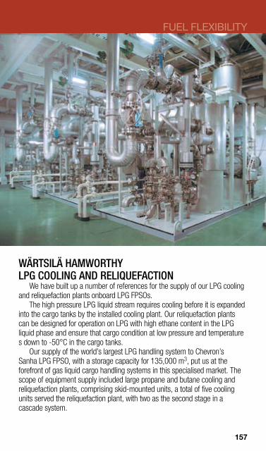
FUEL FLEXIBILITY
WÄRTSILÄ HAMWORTHY LPG COOLING AND RELIQUEFACTION
We have built up a number of references for the supply of our LPG cooling and reliquefaction plants onboard LPG FPSOs.
The high pressure LPG liquid stream requires cooling before it is expanded into the cargo tanks by the installed cooling plant. Our reliquefaction plants can be designed for operation on LPG with high ethane content in the LPG liquid phase and ensure that cargo condition at low pressure and temperature s down to -50°C in the cargo tanks.
Our supply of the world’s largest LPG handling system to Chevron’s Sanha LPG FPSO, with a storage capacity for 135,000 m3, put us at the forefront of gas liquid cargo handling systems in this specialised market. The scope of equipment supply included large propane and butane cooling and reliquefaction plants, comprising skid-mounted units, a total of five cooling units served the reliquefaction plant, with two as the second stage in a cascade system.
157

158
The Wärtsilä Svanehøj range of pumps and pumping systems with frequency converter regulated electric motors is based on more than a century of experience and ongoing development activities. For liquid cargo handling, there is no better business partner.
WÄRTSILÄ SVANEHØJ BOOSTER PUMPS Wärtsilä Svanehøj Booster Pumps are available in both horizontal and vertical execution. The pumps are manufactured in stainless steel AlSl 304 for cargo temperatures down to -104°C. The horizontal booster pump is also available in a multi-stage format for high delivery head applications.
Our booster pumps are delivered as complete units (i.e. mounted on a base plate) and manufactured with flanges according to EN 1092.
158

159
WÄRTSILÄ SVANEHØJ DEEPWELL BALLAST PUMPS Wärtsilä Svanehøj deepwell ballast pumps have been installed on a number of FPSOs.
The deepwell ballast pump is a single suction in-line centrifugal pump, designed for a reliable and efficient operation and consists of a submerged pump head, transmission to deck and electric motor. The compact design of the pump ensures low weight handling.
The pump is designed for direct-on-line starting and can also be operated with a frequency converter or other means of variable speed regulation. The motor will be delivered with a PTB certificate and class certificate where required.
WÄRTSILÄ SVANEHØJ DEEPWELL CARGO & PROCESS PUMPS We offer a wide range of deepwell pumps for process and cargo handling for offshore applications.
For FPSOs/FSOs requiring a distributed pump system, the Wärtsilä Svanehøj range of electrically driven deepwell pumps represents an efficient and cost effective crude handling system. In providing the long term benefits of lower maintenance and less downtime, our deepwell pumps also use less energy than other comparable distributed pump systems.
Our shaft lubrication system enables less onboard maintenance to the electric system. The pump housing is easily dismantled, and cards on the converters are easily interchanged. During the operational phase, the electrical equipment offers environmental sustainability, since CO2 emissions are minimal due to the higher efficiency and lower power utilization, and there is no risk of hydraulic oil spills.
Wärtsilä Svanehøj deepwell process and cargo pumps are designed for continuous operation with pumping mediums such as crude oil and produced water and oil. The type OPC pumps can be delivered according to API 610, and are designed with a capacity from 20–1800 m3/h.
FUEL FLEXIBILITY
159

WÄRTSILÄ SVANEHØJ DEEPWELL CARGO PUMPS FOR GAS CARRIERS Wärtsilä Svanehøj deepwell and booster pumps are intended for the four basic designs of LPG, ammonia, ethylene, ethylene/chemical and LNG carriers. z Fully pressurised tankers, with the cargo at ambient temperatures and a
tank pressure of up to 18 bar. z Fully refrigerated atmospheric tankers, with the cargo cooled down to the
saturation temperature, typically -48°C. z Semi-refrigerated tankers, with the cargo maintained in liquefied form by a
combined cooling/pressure process at temperatures down to -104°C. z LNG tankers, with the cargo cooled down to -163°C Our deepwell pumps are designed to meet the requirements for low temperature resistant materials, using a gas-tight shaft sealing system with a pressurised quenching fluid, and an extremely low NPSH to pump gases at a condition very close to their boiling point
160

WÄRTSILÄ SVANEHØJ DEEPWELL CARGO PUMPS FOR TANKERS Wärtsilä Svanehøj Deepwell cargo pumps have been developed to achieve the highest possible efficiencies, and to meet the latest environmental legislation.
We offer both cargo lubricated and oil lubricated pumps for oil and chemical tankers. These pumps are designed to handle all kinds of cargo while meeting IMO and all major classification society requirements.
Our production facilities enable full scale testing of the cargo pumps. Even pumps of more than 30 meters can be tested in our String test tower.
In addition to deepwell cargo pumps, we also offer all necessary components for the complete cargo pumping system. These include portable cargo pumps, electrical switchboards, frequency converters, explosion proof electrical motors, and cargo control systems.
We have the engineering capabilities to supply a custom made turnkey solution to yards as well as ship owners.
FUEL FLEXIBILITY
161

WÄRTSILÄ SVANEHØJ DEEPWELL SEAWATER LIFT & FIRE WATER PUMPS The Wärtsilä Svanehøj range of deepwell seawater lifting and fire pumps has been designed specifically for the offshore market.
Our seawater lift pumps feature a capacity of up to 2300 m3/hr with a differential pressure of up to 180 mlc. These pumps are driven by dry mounted explosion-proof electric motors via a pipestack with a transmission shaft and seawater lubricated bearings.
For seawater lift and fire pumps installed in caissons, Wärtsilä Svanehøj offers an inflatable intermediate support system. This has been developed in order to secure a proper installation and to support the pump in the caisson. The caisson installed deepwell pump is typically delivered for FPSOs, semisubmersible production units and platforms, and are available according to API 610 upon request.
162
WÄRTSILÄ HAMWORTHY CENTRIFUGAL PUMPS A simple design and few components ensure that Wärtsilä Hamworthy centrifugal pumps are cost-effective and reliable.
Wärtsilä Hamworthy’s centrifugal pumps come in a broad range of sizes to meet a variety of needs. The simple design allows fast and easy servicing and repairs. z We offer a complete range of ballast pumps for all types of vessels, with
capacities ranging from 100 m3/hr to 5,000 m3/hr. The single suction open impeller (C2G model), or double suction impeller (CA model) enable high suction performance (NPSHr).
z The Wärtsilä Hamworthy C2G pump is a single-suction in-line centrifugal pump providing reliable and efficient operation. The compact design means less weight and easier handling, and offers both high suction performance and a low power requirement.
z The CA single stage centrifugal pump is available in both vertical and horizontal designs for capacities from 380 m3/hr to 6000 m3/hr at total heads up to 50 m.w.g.
z The CB single stage centrifugal pumps are available in both vertical and horizontal designs for capacities from 500 m3/h to 7,000 m3/h at total heads up to 200m.w.g.
z Model CG is noted for its robust construction and operating reliability. Its unique hydraulic design gives a compact profile with modest space requirements and less weight for easier handling.
z Dolphin pumps meet the increasing need for alternative forms of pump construction. The range is based on a single entry pump covering capacities from 10 to 500 m3/h, and a larger capacity double entry pump which extends the capability to 2500 m3/h, sufficient to cover any marine pumping duty likely to occur.
FUEL FLEXIBILITY
163
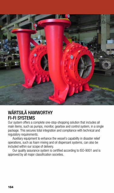
WÄRTSILÄ HAMWORTHY FI-FI SYSTEMS Our system offers a complete one-stop-shopping solution that includes all main items, such as pumps, monitor, gearbox and control system, in a single package. This secures total integration and compliance with technical and regulatory requirements.
Auxiliary equipment to enhance the vessel’s capability in disaster relief operations, such as foam mixing and oil dispersant systems, can also be included within our scope of delivery.
Our quality assurance system is certified according to ISO-9001 and is approved by all major classification societies.
164
WÄRTSILÄ SVANEHØJ PORTABLE PUMPS Wärtsilä Svanehøj hydraulically driven portable pumps are widely used in oil product and chemical tanker applications.
Our single-stage centrifugal pumps are mounted with mechanical shaft seals and a hydraulic motor, built together in an acid-proof housing and protected in such a way that the pump stands submersion into most liquids.
The hydraulically driven portable cargo pumps have an outer diameter that is less than a standard 12” butterworth hatch and can, therefore, be submerged into the cargo tank.
The pumps can be connected either to the ship’s hydraulic system or to a hydraulic power pack unit via a ring line. They are easy to connect using quick couplings, while the manoeuvring of the pump by a flow regulating valve makes for fast and trouble-free handling.
WÄRTSILÄ HAMWORTHY PUMP ROOM SYSTEMS Important features of the Wärtsilä Hamworthy system include compact and space-saving configurations for optimal pump room layouts, combined with high operational efficiency.
Wartsila Hamworthy’s extensive experience, coupled with its ongoing research and development programme, ensures that our pump room systems meet current and anticipated customer requirements, including the latest improvements in FPSOs/FSOs and modern tanker design and operation.
The traditional pump room system is characterised by a separate room for pumping equipment located between the engine room and the cargo hold – an arrangement that provides easy access to all key components for regular inspection and maintenance.
FUEL FLEXIBILITY
165
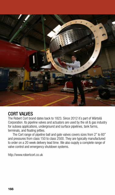
CORT VALVES The Robert Cort brand dates back to 1823. Since 2012 it´s part of Wärtsilä Corporation. Its pipeline valves and actuators are used by the oil & gas industry for subsea applications, underground and surface pipelines, tank farms, terminals, and floating jetties.
The Cort range of pipeline ball and gate valves covers sizes from 2” to 60” and pressures from class 150 to class 2500. They are typically manufactured to order on a 20 week delivery lead time. We also supply a complete range of valve control and emergency shutdown systems.
http://www.robertcort.co.uk
166

JOHN MILLS VALVES The John Mills Valve company dates back to 1828. Since 2012 it´s part of Wärtsilä Corporation. Today its range of products includes bronze and nickel aluminium bronze gate, globe, ball, and check valves for seawater applications in the marine, oil and gas, nuclear, water treatment and chemical industries.
With its own pattern shop, Lloyd’s approved foundry, machine shop, assembly and testing facilities, John Mills has become the chosen partner for engineering valve houses across Europe. We offer non-ferrous valves for the petrochemical and marine industries backed by flexible manufacturing and speedy customer response.
http://www.johnmills-valves.com
SHIPHAM VALVES For more than 200 years, Shipham Valves has supplied quality products. Since 2012 it´s part of Wärtsilä Corporation. Its non-ferrous, composite, and high alloy valve solutions for handling sea water and other severe fluids are available in sizes from 1/2” to 88”, and in materials from bronze to zirconium.
For 80 years a key supplier to the British Royal Navy and Ministry of Defence, Shipham Valves is a global leader in the design and manufacture of valves for handling sea water. Applications include fire fighting and cooling lines in the oil & gas, FPSO, and petro-chemical industries.
Shipham offers the most diverse range of valves by type, material, and size, of any single valve manufacturer in the world. We offer gate, globe, ball, swing check, dual plate check, butterfly and hydrant valves, in sizes from 1/2” to 88” and in materials from bronze to zirconium.
http://www.shipham-valves.com/
FUEL FLEXIBILITY
167

WÄRTSILÄ HAMWORTHY HP AIR AND GAS COMPRESSORS Our high pressure compressors suit a diverse range of marine, industrial and offshore application.
Our compressors can be configured to suit a diverse range of high pressure applications for both air and other compressible gases.
Our compressors can handle the following gases; z Air z Argon z Biogas z Carbon Dioxide z Helium z Heliox z Hydrogen z Methane z Natural Gas z Nitrogen (both compression and generation)
168

WÄRTSILÄ HAMWORTHY SEISMIC COMPRESSORS Our seismic compressors offer an integrated and compact solution to your high-pressure needs.
Wärtsilä Hamworthy seismic compressors feature a low lift concentric valve and generous inter-stage cooling to minimise the amount of absorbed power. This results in very high overall efficiency.
Each machinery package includes a choice of drive, skid base and control system, and is engineered to suit your seismic requirements.
The low unit noise and vibration improves reliability and reduces interference with survey results. Flexibility in vessel utilization is available to contractors and operators via the containerised option. Thanks to the easy access features and simple modular construction, it enables low and easy maintenance. A multiple unit control system provides local and remote operation of two or more compressors.
FUEL FLEXIBILITY
169

WÄRTSILÄ HAMWORTHY RIG TENSIONING COMPRESSORS Our rig tensioning compressors and heave compensation compressor packages are fully integrated, lightweight, compact and engineered for the offshore environment.
The combination of a 4-stage compressor, dryer, and filtration package with a contained cooling system, produces filtered and dry, high pressure air or gas suitable for riser tensioning and other offshore applications. The packages are designed to ensure that upgrades, refurbishment, and servicing can be easily carried out.
We also offer high pressure nitrogen booster compressors, along with nitrogen generation systems, for riser tensioning and other applications.
These units can be supplied as integrated packages, fully assembled, tested and ready for installation. The module also meets the requirements of the major marine classification societies.
170
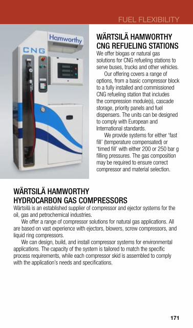
WÄRTSILÄ HAMWORTHY CNG REFUELING STATIONS We offer biogas or natural gas solutions for CNG refueling stations to serve buses, trucks and other vehicles.
Our offering covers a range of options, from a basic compressor block to a fully installed and commissioned CNG refueling station that includes the compression module(s), cascade storage, priority panels and fuel dispensers. The units can be designed to comply with European and International standards.
We provide systems for either ‘fast fill’ (temperature compensated) or ‘timed fill’ with either 200 or 250 bar g filling pressures. The gas composition may be required to ensure correct compressor and material selection.
WÄRTSILÄ HAMWORTHY HYDROCARBON GAS COMPRESSORS Wärtsilä is an established supplier of compressor and ejector systems for the oil, gas and petrochemical industries.
We offer a range of compressor solutions for natural gas applications. All are based on vast experience with ejectors, blowers, screw compressors, and liquid ring compressors.
We can design, build, and install compressor systems for environmental applications. The capacity of the system is tailored to match the specific process requirements, while each compressor skid is assembled to comply with the application’s needs and specifications.
FUEL FLEXIBILITY
171
WÄRTSILÄ MOSS FLUE GAS The unique design of the Wärtsilä Moss Flue Gas System has been proven through thousands of installations.
The system’s unique design incorporates high efficiency, low maintenance costs, safe and easy operation, combined with minimum space requirements. High quality materials and an excellent control system assure long life and reliability.
The Wärtsilä Moss Flue Gas System is tailor made for use on board crude oil carriers. Its design is based on compact modules, offering valuable savings in space and installation costs, both for new buildings and for retrofitting to existing vessels.
An efficient topping up generator is also used in conjunction with the Flue Gas System, making high inert gas quality possible by a purpose designed combustion chamber.
WÄRTSILÄ MOSS INERT GAS GENERATORS Our inert gas generator systems ensures the correct atmosphere in the cargo tanks and pipes to minimize the risk of explosion.
Wärtsilä Hamworthy has over 20 years experience in the design and manufacturing of inert gas generator systems . These unique systems are well known for their high quality with regard to material selection and inert gas quality.
The Moss design includes special features such as burner/scrubber units that require less deck space than conventional blower units, inert gas cooling, inert gas drying and a control system.
Our years of experience in operating under extreme conditions allow us to efficiently handle upgrades to system regulation, component cooling and capacity tuning. The design is based on compact modules, offering important savings in space and installation time.
172
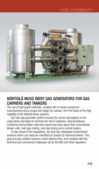
WÄRTSILÄ MOSS INERT GAS GENERATORS FOR GAS CARRIERS AND TANKERS The use of high grade materials, coupled with in-house component manufacturing and a unique two-stage fan solution, form the basis of the high reliability of the Wärtsilä Moss systems.
Our inert gas generator system ensures the correct atmosphere in the cargo tanks and pipes to minimize the risk of explosion. Special features include burner/scrubber units that require less deck space than conventional blower units, inert gas cooling, inert gas drying and a control system.
To stay ahead of the regulations, we have also developed containerized solutions which can easily be retrofitted on product & chemical tankers. This plug and play solution ensures a short delivery time, and complies with the technical and commercial challenges set by the IMO and other regulators.
FUEL FLEXIBILITY
173
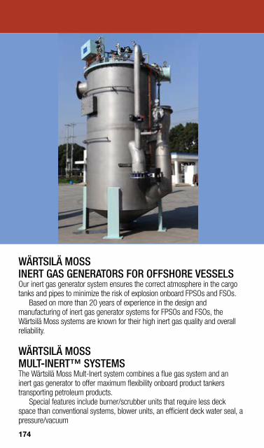
WÄRTSILÄ MOSS INERT GAS GENERATORS FOR OFFSHORE VESSELS Our inert gas generator system ensures the correct atmosphere in the cargo tanks and pipes to minimize the risk of explosion onboard FPSOs and FSOs.
Based on more than 20 years of experience in the design and manufacturing of inert gas generator systems for FPSOs and FSOs, the Wärtsilä Moss systems are known for their high inert gas quality and overall reliability.
WÄRTSILÄ MOSS MULT-INERT™ SYSTEMS The Wärtsilä Moss Mult-Inert system combines a flue gas system and an inert gas generator to offer maximum flexibility onboard product tankers transporting petroleum products.
Special features include burner/scrubber units that require less deck space than conventional systems, blower units, an efficient deck water seal, a pressure/vacuum
174

FUEL FLEXIBILITY
WÄRTSILÄ MOSS NITROGEN GENERATORS Our nitrogen generators are compact and highly efficient systems based on air separation using hollow fibre membrane modules which utilise state-of-the-art membrane technology.
Wärtsilä Moss nitrogen generators utilise state-of-the-art membrane technology, and have served marine market applications for many years. The system is particularly suited for chemical carriers, gas carriers and offshore vessels.
We also supply niche, supplementary, small-volume systems with a capacity of 2,000N m3/h to 3,750N m3/h with 95% purity, and have now further developed our technology to enable our nitrogen generators to become efficient large-scale main inert gas units.
For the offshore market, Wärtsilä Moss nitrogen generation systems supply dry and oil-free inert gas for purging, pressurising, and blanketing functions for various top site applications. These systems consist of two 100% inlet air filters, a pre-heater with thyristor control, separator membranes, an O2 analyser, UCP, and the controls and instruments for safe and automatic operation.
175
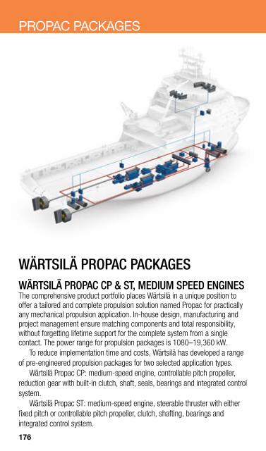
PROPAC PACKAGES
WÄRTSILÄ PROPAC PACKAGES WÄRTSILÄ PROPAC CP & ST, MEDIUM SPEED ENGINES The comprehensive product portfolio places Wärtsilä in a unique position to offer a tailored and complete propulsion solution named Propac for practically any mechanical propulsion application. In-house design, manufacturing and project management ensure matching components and total responsibility, without forgetting lifetime support for the complete system from a single contact. The power range for propulsion packages is 1080–19,360 kW.
To reduce implementation time and costs, Wärtsilä has developed a range of pre-engineered propulsion packages for two selected application types.
Wärtsilä Propac CP: medium-speed engine, controllable pitch propeller, reduction gear with built-in clutch, shaft, seals, bearings and integrated control system.
Wärtsilä Propac ST: medium-speed engine, steerable thruster with either fixed pitch or controllable pitch propeller, clutch, shafting, bearings and integrated control system.
176
WÄRTSILÄ PROPAC LS, LOW-SPEED ENGINES Wärtsilä propulsion packages that combine low-speed engines and controllable or fixed pitch propellers are available. They are integrated mechanical propulsion system products with lifetime support. The packages are tailor-engineered to suit individual project requirements.
The Wärtsilä low-speed propulsion packages are based on timeproven technological expertise, an unrivalled range of leading products and close customer support. Customer support extends from initial design to construction and operation.
Scope of low-speed propulsion packages: z Two-stroke, low-speed engine, designed for marine installation z State-of-the-art controllable pitch or fixed pitch propeller z Shafting with intermediate bearings z Sterntube with bearings z Shaft seals z Integrated propulsion control systems
Benefits to shipowners and shipyards: z Turnkey responsibility for complete package z In-house design, manufacturing and project management z Rapid implementation z Highly reliable seaworthy low-speed main engine for unrestricted service z Low fuel consumption with heavy fuel oil z Easy installation – simple mechanical and automation interfaces z Comprehensive documentation and user manuals z Lifetime support – best worldwide service network
177

SOLUTIONS COMPARISON TOOLS
Bow thrusters
Bridge control panel
Ship design
Manoeuvring thruster
Main engine generator sets
Gas valve units
Coldbox
Bunkering stations
Switch gear Engine control room
LNG storage tank
Azimuth main propulsion units
SOLUTIONS COMPARISON TOOLS Wärtsilä has set forward a new approach to the lifecycle of the vessel by getting involved at all stages, from ship design to new buildings or repowering of the complete propulsion system and finally for the services of the ship.
The global question behind the design of a vessel is the efficiency of the propulsion system.
According to Wärtsilä, everything starts from the interaction between the hull and the propulsors.
Then significant total savings can be found by optimizing the propeller design and matching it with the prime movers.
Engine selection is another key element to improve the overall efficiency. Wärtsilä offers the configuration which provides the ability to match and run the engines close to optimum efficiency.
The propulsion packages are developed according to the mission profile of the vessel as defined by the end-user.
178

Wärtsilä develop solutions comparison tools where solutions can be compared in terms of fuel consumption, emissions, investment cost, payback time, profitability. We can help customer to select the solution which fits the most with his needs according to ship operation profile and selected machinery concepts.
179

180

SERVICES
THREE SERVICES ROUTES TO BIGGER PROFITS
Wärtsilä Services improve lifecycle efficiency
by preventing the unexpected, improving environmental efficiency and optimising
performance. Let’s work together to find
the right route for you.
181

WÄRTSILÄ SERVICES: LIFECYCLE EFFICIENCY SOLUTIONS Wärtsilä Services supports its customers by offering the most comprehensive portfolio of services in the industry, thereby optimising their operations and the lifecycle performance of their installations. Our services network is the broadest in the industry, consisting of more than 11,000 service professionals in over 160 locations in more than 70 countries. We offer expertise, local availability, responsiveness, and environmentally sound actions for all customers, regardless of the make of their equipment.
WE OFFER LIFECYCLE EFFICIENCY SOLUTIONS IN THE FOLLOWING AREAS OF EXPERTISE: z Engine services z Propulsion services z Electrical & automation services z Boiler services z Environmental services z Service agreements z Service projects z Training services
182
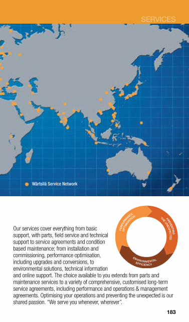
SERVICES
Our services cover everything from basic support, with parts, field service and technical support to service agreements and condition based maintenance; from installation and commissioning, performance optimisation, including upgrades and conversions, to environmental solutions, technical information and online support. The choice available to you extends from parts and maintenance services to a variety of comprehensive, customised long-term service agreements, including performance and operations & management agreements. Optimising your operations and preventing the unexpected is our shared passion. “We serve you whenever, wherever”.
Wärtsilä Service Network
183
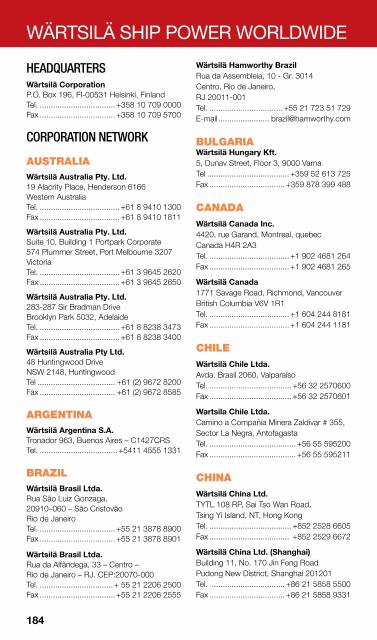
WÄRTSILÄ SHIP POWER WORLDWIDE
HEADQUARTERS Wärtsilä Corporation P.O. Box 196, FI-00531 Helsinki, Finland Tel. .................................. +358 10 709 0000 Fax .................................. +358 10 709 5700
CORPORATION NETWORK
AUSTRALIA Wärtsilä Australia Pty. Ltd. 19 Alacrity Place, Henderson 6166 Western Australia Tel. .................................... +61 8 9410 1300 Fax .................................... +61 8 9410 1811
Wärtsilä Australia Pty. Ltd. Suite 10, Building 1 Portpark Corporate 574 Plummer Street, Port Melbourne 3207 Victoria Tel. .................................... +61 3 9645 2620 Fax .................................... +61 3 9645 2650
Wärtsilä Australia Pty. Ltd. 283-287 Sir Bradman Drive Brooklyn Park 5032, Adelaide Tel. .................................... +61 8 8238 3473 Fax .................................... +61 8 8238 3400
Wärtsilä Australia Pty Ltd. 48 Huntingwood Drive NSW 2148, Huntingwood Tel ................................... +61 (2) 9672 8200 Fax .................................. +61 (2) 9672 8585
ARGENTINA Wärtsilä Argentina S.A. Tronador 963, Buenos Aires – C1427CRS Tel. ................................... +5411 4555 1331
BRAZIL Wärtsilä Brasil Ltda. Rua São Luiz Gonzaga, 20910–060 – São Cristovão Rio de Janeiro Tel. .................................. +55 21 3878 8900 Fax .................................. +55 21 3878 8901
Wärtsilä Brasil Ltda. Rua da Alfândega, 33 – Centro – Rio de Janeiro – RJ. CEP:20070-000 Tel. ................................. + 55 21 2206 2500 Fax .................................. +55 21 2206 2555
Wärtsilä Hamworthy Brazil Rua da Assembleia, 10 - Gr. 3014 Centro, Rio de Janeiro, RJ 20011-001 Tel. ................................. +55 21 723 51 729 E-mail ....................... [email protected]
BULGARIA Wärtsilä Hungary Kft. 5, Dunav Street, Floor 3, 9000 Varna Tel ..................................... +359 52 613 725 Fax .................................. +359 878 399 488
CANADA Wärtsilä Canada Inc. 4420, rue Garand, Montreal, quebec Canada H4R 2A3 Tel. .................................... +1 902 4681 264 Fax .................................... +1 902 4681 265
Wärtsilä Canada 1771 Savage Road, Richmond, Vancouver British Columbia V6V 1R1 Tel. .................................... +1 604 244 8181 Fax .................................... +1 604 244 1181
CHILE Wärtsilä Chile Ltda. Avda. Brasil 2060, Valparaíso Tel. ..................................... +56 32 2570600 Fax ..................................... +56 32 2570601
Wartsila Chile Ltda. Camino a Compañía Minera Zaldívar # 355, Sector La Negra, Antofagasta Tel. ....................................... +56 55 595200 Fax ....................................... +56 55 595211
CHINA Wärtsilä China Ltd. TYTL 108 RP, Sai Tso Wan Road, Tsing Yi Island, NT, Hong Kong Tel. ..................................... +852 2528 6605 Fax .................................... +852 2529 6672
Wärtsilä China Ltd. (Shanghai) Building 11, No. 170 Jin Feng Road Pudong New District, Shanghai 201201 Tel. ................................. +86 21 5858 5500 Fax .................................. +86 21 5858 9331
184
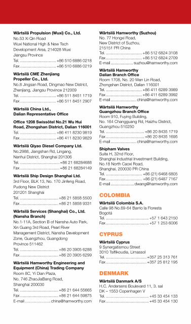
WÄRTSILÄ SHIP POWER WORLDWIDE
Wärtsilä Propulsion (Wuxi) Co., Ltd. No.53 Xi Qin Road Wuxi National High & New Tech Development Area, 214028 Wuxi Jiangsu Province Tel. ................................ +86 510 6886 0218 Fax ................................ +86 510 6886 0219
Wärtsilä CME Zhenjiang Propeller Co., Ltd. No.8 Jingsan Road, Dingmao New District, Zhenjiang, Jiangsu Province 212009 Tel. ................................ +86 511 8451 1719 Fax ................................ +86 511 8451 2907
Wärtsilä China Ltd., Dalian Representative Office
Office 1208 Swissôtel No.21 Wu Hui Road, Zhongshan District, Dalian 116001 Tel. ................................ +86 411 8230 9819 Fax ................................ +86 411 8230 9829
Wärtsilä Qiyao Diesel Company Ltd. No.2988, Jiangshan Rd, Lingang, Nanhui District, Shanghai 201306 Tel. ................................... +86 21 68284688 Fax ................................... +86 21 68284149
Wärtsilä Ship Design Shanghai Ltd. 3rd Floor, BLK 13, No. 170 Jinfeng Road, Pudong New District 201201 Shanghai Tel. .................................. +86 21 5858 5500 Fax .................................. +86 21 5858 9331
Wärtsilä Services (Shanghai) Co., Ltd. (Nansha Branch) No.1-11A, Section B of Nansha Auto Park, Xin Guang 3rd Road, Pearl River Management District, Nansha Development Zone, Guangzhou, Guangdong Province 511462 Tel. .................................. +86 20 3905 6288 Fax .................................. +86 20 3905 6299
Wärtsilä Hamworthy Engineering and Equipment (China) Trading Company Room 8C, Yi Dian Plaza, No. 746 ZhaoJiaBang Road, Shanghai 200030 Tel. .................................. +86 21 644 55665 Fax .................................. +86 21 644 59875 E-mail ....................... [email protected]
Wärtsilä Hamworthy (Suzhou) No. 77 Hongxi Road, New District of Suzhou, 215151 PR China Tel. ................................ +86 512 6824 3108 Fax ................................ +86 512 6824 2709 E-mail .................... [email protected]
Wärtsilä Hamworthy Dalian Branch Office Room 1708, No. 20 Wen Lin Road, Zhongshan District, Dalian 116001 Tel. ................................ +86 411 6289 3989 Fax ................................ +86 411 6289 3992 E-mail ....................... [email protected]
Wärtsilä Hamworthy Guangzhou Branch Office Room 910, Fuying Building, No. 164 Changguang Rd, Haizhu District, Guangzhou 510250 Tel. .................................. +86 20 8435 1719 Fax .................................. +86 20 8435 1695 E-mail ....................... [email protected]
Shipham Valves Suite H, 32nd Floor, Shanghai Industrial Investment Building, No.18 North Caoxi Road, Shanghai, 200030 PR China Tel. ................................ +86 (21) 6468 6805 Fax ................................ +86 (21) 6487 7167 E-mail [email protected]
COLOMBIA Wärtsilä Colombia S.A. Calle 98 No.69-64 Barrio la Floresta Bogotá Tel. ...................................... +57 1 643 2150 Fax ...................................... +57 1 253 6006
CYPRUS Wärtsilä Cyprus 9 Synergatismou Street 3010 Tsiflikoudia, Limassol Tel. .................................... +357 25 313 761 Fax .................................... +357 25 812 195
DENMARK Wärtsilä Danmark A/S H.C. Andersens Boulevard 11, 3. sal DK – 1553 Copenhagen V Tel. ...................................... +45 33 454 133 Fax ...................................... +45 33 454 130

WÄRTSILÄ SHIP POWER WORLDWIDE
Wärtsilä Danmark A/S Jens Munksvej 1, P.O.Box 67, DK-9850 Hirtshals Tel. ...................................... +45 99 569 956 Fax ...................................... +45 98 944 016
Wärtsilä Hamworthy Svanehøj PO Box 30, 6 Fabriksparken, DK-9230 Svenstrup J Tel. ..................................... +45 96 37 22 00 Fax ..................................... +45 98 38 31 56 E-mail [email protected]
DOMINICAN REPUBLIC Wärtsilä Dominicana, SRL C/El Recodo #4, Bella Vista Santo Domingo Dominican Republic Tel. .................................. +1 (809) 564 4440 Fax .................................. +1 (809) 372 7968
Wärtsilä Dominicana, SRL Km 13 ½ Aut. Duarte, Alameda Santo Domingo Oeste Dominican Republic Tel. .................................. +1 (809) 561 2022 Fax .................................. +1 (809) 372 7968
FINLAND Wärtsilä Finland Oy Järvikatu 2–4, P.O. Box 244 FI-65101 Vaasa Tel. ................................. +358 10 709 0000 Fax .................................... +358 6 317 1906
Wärtsilä Finland Oy Tarhaajantie 2 FI-65380 Vaasa Tel. .................................. +358 10 709 0000 Fax .................................... +358 6 356 7188
Wärtsilä Finland Oy Stålarminkatu 45, P.O. Box 50, FI-20811 Turku Tel. ................................. +358 10 709 0000 Fax .................................... +358 2 234 2419
FRANCE Wärtsilä France S.A.S. 3 Boulevard de la Loire, PO Box 97511 FR-44275 Nantes cedex 2 Tel. .................................... +33 2 4041 1602 Fax .................................... +33 2 4041 1600
Wärtsilä France S.A.S. La Combe, Boîte postale 1213 F - 17700 Surgeres Cedex Tel. .................................. +33 5 46 30 31 32 Fax .................................. +33 5 46 07 35 37
GERMANY Wärtsilä Deutschland GmbH Bernhard-Nocht-Str. 113 20359 Hamburg Tel. .................................. +49 40 75190 222 Fax .................................. +49 40 75190 249
Wärtsilä Ship Design Germany GmbH Bernhard-Nocht-Str. 113 20359 Hamburg Tel. ..................................... +49 40 37 60 90 Fax ..................................... +49 40 37 33 15
Wärtsilä Hamworthy Serck Como GmbH Pankower Str. 16-18, D-21502 Geesthacht Tel. ...................................... +49 4152 805 0 Fax .................................. +49 4152 805 105 E-mail .............. [email protected]
GREAT BRITAIN Wärtsilä UK Ltd. 11a Peterseat Drive, Altens, Aberdeen AB12 3HT, Scotland Tel. ................................... +44 1224 871166 Fax ................................... +44 1224 871188
Wärtsilä UK Ltd. 4 Marples Way, Havant, Hants PO9 1NX Tel. ................................. +44 2392 400 121 Fax .................................. +44 2392 492 470
Wärtsilä Hamworthy Water Systems Fleets Corner, Poole, Dorset BH17 0JT, England. Tel. ................................... +44 1202 662600 Fax ................................... +44 1202 668793 E-mail .......................... [email protected]
Wärtsilä Hamworthy Krystallon Channel View Road Dover, Kent CT17 9TP, England. Tel. ................................... +44 1304 245820 E-mail [email protected]
John Mills Valves 509 Shields Road, Walkergate Newcastle Upon Tyne NE6 4PX Tel. ................................... +44 191 2656550 Fax ................................... +44 191 2651002 E-mail [email protected]
186

WÄRTSILÄ SHIP POWER WORLDWIDE
Leeds Valve Town End, Gildersome Leeds, West Yorkshire LS27 7HF Tel. ................................... +44 113 2525051 Fax ................................... +44 113 2525986 E-mail ....................... [email protected]
Robert Cort Valves Ltd 30 Robert Cort Industrial Estate, Britten Road, Reading, Berkshire RG2 0AU Tel .................................... +44 118 9874311 Fax ................................... +44 118 9866592 E-mail [email protected]
Shipham Valves Hawthorn Avenue, Hull East Yorkshire HU3 5JX Tel. ................................... +44 1482 323163 Fax ................................... +44 1482 224057 E-mail [email protected]
GREECE Wärtsilä Greece S.A. 25 Akti Miaouli 185 35 Piraeus Tel. ................................. +30 2 10 413 5450 Fax ................................. +30 2 10 411 7902
ICELAND Vélar og Skip ehf. Hólmaslóð 4, 101 Reykjavik Tel. ...................................... +354 56 200 95 Fax ...................................... +354 56 210 95
INDIA Wärtsilä India Ltd. Kesar Solitaire, Plot no 5, Sector-19 Sanpada, Navi Mumbai - 400705 Tel. ........................+91 22 2781 8300 /8550 Fax ................................... +91 22 27818468
Wärtsilä Ship Design India Ltd. Raaji Towers # 10/14, 8th Street, Gopalapuram, Chennai - 600 086 Tel. .................................. +91 44 4297 2000 Fax .................................. +91 44 4297 2022
Wärtsilä Hamworthy (India) 35, Mittal Chambers, Nariman Point Mumbai - 400 021 Tel. ..............................+91 22 30287711-15 Fax ................................... +91 22 30287710 E-mail ........................ [email protected]
INDONESIA P.T. Wärtsilä Indonesia Cikarang Industrial Estate JL. Jababeka XVI, Kav. W-28 Bekasi 17530, Jawa Barat Tel. ................................... +62 21 893 76 54 Fax ................................... +62 21 893 76 60
P.T. Wärtsilä Indonesia Graha Surya Internusa 10th Fl. Suite 1006, Jl. H.R. Rasuna Said Kav. X-O Jakarta 12950 Tel. ................................... +62 21 57930515 Fax ................................... +62 21 57930516
IRAN Rahpooyan Company Wärtsilä representative of Ship Power and Services, Unit 4, 11th floor, Pam TowerDastgerdi, St.Afarica Blvd. P.O. Box 14335 – 656, Tehran Tel. ................................ +9821 8887 0220 1 Tel. ................................ +9821 8879 1940 1 Fax ................................. +9821 8866 01016
ITALY Wärtsilä Italia S.p.A. Via dei Pescatori , IT-16128 Genova Tel. ..................................+39 010-2530 863 Fax ..................................+39 010-2543 902
Wärtsilä Italia S.p.A. Bagnoli della Rosandra, 334 San Dorligo della Valle, 34018 Trieste Tel ................................... +39 040 319 5000 Fax .................................. +39 040 319 5728
JAPAN Wärtsilä Japan Ltd. 5th Floor, NTC Building, 1–11–2 Kyobashi, Chuo-ku, Tokyo 104–0031 Tel. .................................... +81 3 5159 8700 Fax .................................... +81 3 5159 8710
Wärtsilä Japan Ltd. 6–7–2, Minatojima Chuo-ku, Kobe 650–0045 Tel. .................................... +81 78 304 7511 Fax .................................... +81 78 302 5143

WÄRTSILÄ SHIP POWER WORLDWIDE
Wärtsilä Japan Ltd. Toyama Factory 14–37, 7-Chome, Mukaishinjyo-machi Toyama 930–0916 Tel. .................................... +81 76 451 3150 Fax .................................... +81 76 451 3161
KOREA Wärtsilä Korea Ltd. 651-16, Eomgung-dong, Sasang-gu, Busan 617–831 Tel. .................................... +82 51 329 0500 Fax .................................... +82 51 324 4349
Wärtsilä Hamworthy Korea 8th Floor, Yoosung Plaza Building #655-6 Woo-dong, Haeundae-Gu, Busan 612-020 Tel. .................................... +82 51 741 3724 Fax .................................... +82 51 741 9961 E-mail [email protected]
MALAYSIA Wärtsilä Malaysia Sdn Bhd. 55-02 Jalan Molek, 3/1 Taman Molek, 81100 Johore Bahru Tel. .................................. +60 (07) 355 5560 Fax .................................. +60 (07) 355 5560
CWA Marine Sdn Bhd 55-02 Jalan Molek 3/1 Taman Molek, 81100, Johore Bahru
MOROCCO Société Salva 93, Boulevard de la Résistance Casablanca 21700 Tel. .................................... +212 2 2304 038 Fax .................................... +212 2 2306 675
NEW ZEALAND Wärtsilä New Zealand Ltd. HMNZ Dockyard, Queens Parade Devonport, Auckland, NZ 0624 Tel. ...................................... +64 9 445 3495
THE NETHERLANDS Wärtsilä in the Benelux Hanzelaan 95, P.O. Box 10608, 8000 GB Zwolle Tel. .................................... +31 38 4253 253 Fax .................................... +31 38 4253 352
Wärtsilä Netherlands B.V. Lipsstraat 52, P.O. Box 6, 5150 BB Drunen Tel. ..................................... +31 416 388115 Fax ..................................... +31 416 373162
Wärtsilä Hamworthy Rotterdam Aploniastraat 33, 3084 CC Rotterdam Tel. .................................... +31 10 462 4777 Fax .................................... +31 10 415 9046 E-mail ............. [email protected]
NORWAY Wärtsilä Norway AS
Verftsvegen 115, P.O. Box 684, NO-5404 Stord Tel. ..................................... +47 53 42 25 00 Fax ..................................... +47 53 42 25 01
Wärtsilä Norway AS NO-5420 Rubbestadneset Tel. ..................................... +47 53 42 25 00 Fax ..................................... +47 53 42 25 01
Wärtsilä Norway AS Stenersgata 2, P.O.Box 8905 Youngstorget NO-0028 Oslo Tel. ..................................... +47 53 42 28 40 Fax ..................................... +47 53 42 28 41
Wärtsilä Norway AS Jåttåvågveien 7, N-4065 Stavanger, Norway P.O. Box 130, N-4065 Stavanger, Tel. ..................................... +47 53 42 25 00 Fax ..................................... +47 53 42 25 01
Wärtsilä Norway AS Stiklestadveien 1, 7041 Trondheim Tel ...................................... +47 53 42 25 00 Fax ..................................... +47 53 42 25 01
Wärtsilä Ship Design Norway AS 5419 Fitjar Tel. ..................................... +47 53 45 70 00 Fax ..................................... +47 53 45 70 01
Wärtsilä Hamworthy Oil & Gas Systems P.O. Box 144, NO-1371 Asker Tel. ...................................... +47 815 48 500 Fax ...................................... +47 815 48 510 E-mail [email protected]
Wärtsilä Hamworthy Moss PO Box 1053, NO-1510 Moss Tel. ..................................... +47 69 27 99 00 Fax ..................................... +47 69 25 45 78 E-mail [email protected]
188

WÄRTSILÄ SHIP POWER WORLDWIDE
PANAMA Wärtsila Panama,S.A. Panama Pacífico, Flex #2, Local #3, Brujas Ave., Former Howard Air Force Base Veracruz, Arraijan Tel. .........................................507-304-7400 Fax .........................................507-304-7494
PAPUA NEW GUINEA Wärtsilä PNG Ltd. Porebada Road, Motukea Island Port Moresby Tel. ....................................+675 321 8160/8 Fax ....................................... +675 321 8169
PERU Wärtsilä Perú S.A.C. Pasaje Mártir Olaya N° 129 Centro Empresarial José Pardo Torre “A”, Piso 11, Oficina 1101 Miraflores, Lima-18 Tel. ...................................... +51 1 241 7030 Fax ...................................... +51 1 444 6867
PHILIPPINES Wärtsilä Philippines Inc. No 6, Diode Street, Light Industry and Science Park Bo, Diezmo, Cabuyao, Laguna Tel. ...................................... +63 2 843 7301 Fax .................................... +63 49 543 0381
POLAND Wärtsilä Polska Sp. z o.o. Branch Office in Gdańsk Ul. Twarda 12 80–871 Gdańsk Tel. ................................... +48 58 345 23 44 Fax ................................... +48 58 341 67 44
Wärtsilä Polska Sp. z o.o. Ul. Jakuba Kubickiego 13, 02–954 Warszawa Tel. .................................... +48 22 550 6171 Fax .................................... +48 22 550 6173
Wärtsilä Ship Design Poland Sp. z o.o. ul. Łużycka 2, 81-537 Gdańsk Tel. ................................... +48 58 622 63 13 Fax ................................... +48 58 622 62 65
Wärtsilä Hamworthy Baltic Design Centre Luzycka Str 6e, 81-537 Gdynia Tel. ................................... +48 58 718 61 50 Fax ................................... +48 58 718 61 50 E-mail ..................... [email protected]
PORTUGAL Wärtsilä Portugal, S.A. Zona Industrial Maia I – Sector X – Lotes 362, 363, 4471-909 MAIA Tel ................................... +351 229 439 720 Fax .................................. +351 229 439 729
RUSSIA Wärtsilä Vostok LLC Business centre Linkor 36 A Petrogradskaya naberezhnaya 197101 St. Petersburg Tel. .................................... +7 812 448 3248 Fax .................................... +7 812 448 3241
Wärtsilä Vostok LLC Branch in Vladivostok Utkinskaya str., 9, 1st floor, RU-690091 Vladivostok Tel. ..................................... +7 4232 401600 Fax ..................................... +7 4232 432004
Wärtsilä Ship Design Russia CJSC Office 3, bld 16/9, Sisters Rukavishnikovy’s Nizhni Novgorod, Russia 603146 Tel. ..................................... +47 53 45 81 00
SAUDI ARABIA Wärtsilä Power Contracting Company Ltd. Khalid Bin Al Waleed St., P.O.Box 2132, Jeddah 21451 Tel. .................................... +966 2 651 9001 Fax .................................... +966 2 650 3882
SINGAPORE Wärtsilä Singapore Pte Ltd. 14 Benoi Crescent Singapore 629977 Tel. ....................................... +65 6265 9122 Fax ....................................... +65 6264 0802
Wärtsilä Ship Design Singapore Ptd Ltd. 14 Benoi Crescent Singapore 629977 Tel. ........................................+65-65621138 Fax ........................................+65-65621238

WÄRTSILÄ SHIP POWER WORLDWIDE
Wärtsilä Hamworthy Singapore 15 Benoi Crescent, Singapore 629978 Tel. ....................................... +65 6261 6066 Fax ....................................... +65 6261 6011 E-mail ................ [email protected]
SERBIA Wärtsilä Ship Design Serbia d.o.o Vrsacka 67, 21000 Novi Sad Tel. .................................... +381 21 500 101
SOUTH AFRICA Wärtsilä South Africa (Pty) Ltd. 20 Dorsetshire Street, Cape Town Paarden Eiland 7405 P.O. Box 356, Cape Town Paarden Eiland 7420 Tel. .................................... +27 21 511 1230 Fax .................................... +27 21 511 1412
SPAIN Wärtsilä Ibérica, S.A. Polígono Industrial Landabaso, s/n, 48370 Bermeo Tel. .................................... +34 94 6170 100 Fax .................................... +34 94 6170 105
Wärtsilä Ibérica, S.A. Avda. Juan Carlos 1, No. 3, Apartado 46 ES-39600 Maliaño (Cantabria) Tel. .................................... +34 94 6170 100 Fax .................................... +34 942 254 548
Wärtsilä Hamworthy Pump Systems Avda Doctor Tourón 1, ES-36600 Villagarcia de Arosa (PO) Tel. .................................... +34 986 566 538 Fax .................................... +34 986 566 539 E-mail ....................... [email protected]
SWEDEN Wärtsilä Sweden AB Götaverksgatan 10, P.O. Box 8006 SE-40277 Gothenburgh Tel. .................................... +46 31 744 4600 Fax .................................... +46 31 744 4670
SWITZERLAND Wärtsilä Switzerland Ltd. Zürcherstrasse 12, P.O. Box 414 CH-8401 Winterthur Tel. ................................... +41 52 262 49 22 Fax ................................... +41 52 262 07 18
TAIWAN Wärtsilä Taiwan Ltd. 4F, No. 68, Sec 2, Zhongshan N Road Zhongshan District, Taipei City Tel. .................................. +886 2 2522 2239 Fax .................................. +886 2 2522 2550
TURKEY Wärtsilä Enpa Dis Ticaret A.S. Aydıntepe Mah. D-100 Karayolu (E-5) Cad. No. 14/D, Bahar Is Merkezi. 34947 Tuzla – Istanbul Tel. .................................. +90 216 494 5050 Fax .................................. +90 216 494 5048
Aliağa Workshop: Aliağa Organize Sanayi Bölgesi Necati Atıl Akkan Bulvarı No :8/1 35800 Aliağa – İzmir – Türkiye Tel. ................................. +90 232 621 51 30 Fax ................................. +90 232 621 51 31 24 hours service ............. +90 533 695 05 77
UNITED ARAB EMIRATES Wärtsilä Gulf FZE DIP Plot 597-572, Dubai Investment Park 2, Dubai, United Arab Emirates Tel. ..................................... +9714 885 7222 Fax ..................................... +9714 885 7020
Wärtsilä Hamworthy Middle East PO Box 120691, W/H P6-86, SAIF Zone, Sharjah, United Arab Emirates Tel. ..................................... +971 655 74806 Fax ..................................... +971 655 74807 E-mail [email protected]
U.S.A. Wärtsilä North America, Inc. 900 Bestgate Road, Suite 400, Annapolis Maryland 21401 Tel. .................................... +1 410 573 2100 Fax .................................... +1 410 573 2200
Wärtsilä Defense, Inc. 3617 Koppens Way, Chesapeake Virginia 23323 Tel. .................................... +1 757 966 5410 Fax .................................... +1 757 487 3658 Wärtsilä North America, Inc. 2900 S.W. 42nd Street, Ft. Lauderdale FL 33312 Tel. .................................... +1 954 327 4700 Fax .................................... +1 954 327 4773
190

WÄRTSILÄ SHIP POWER WORLDWIDE
Wärtsilä North America, Inc. 16330 Air Center Boulevard, Houston, TX 77032 Tel. .................................... +1 281 233 6200 Fax .................................... +1 281 233 6233
Wärtsilä North America, Inc. 819 Central Avenue, Jefferson, LA 70121 Tel. .................................... +1 504 733 2500 Fax .................................... +1 504 734 7730
Wärtsilä Defense, Inc. 26264 Twelve Trees Lane, Poulsbo Washington 98370–9435 Tel. .................................... +1 360 779 1444 Fax .................................... +1 360 779 5927
Wärtsilä North America, Inc. 6306 215th Street SW, Suite 3 Mountlake Terrace, WA 98043 Tel. .................................... +1 425 640 8280 Fax .................................... +1 425 640 5162
Wärtsilä North America, Inc. 2140 Technology Place, Bldg #5 Long Beach, CA 90810 Tel. .................................... +1 562 495 8484 Fax .................................... +1 562 495 8430
Wärtsilä Hamworthy Inc (Houston) 11111 Katy Freeway, Suite 910 Houston, TX 77079 Tel. .................................... +1 281 759 3280 Fax .................................... +1 281 759 8308 E-mail [email protected]
Wärtsilä Hamworthy Inc (Miami) 8000 NW 31 Street, Unit 13 Miami, Florida 33122 Tel. .................................... +1 305 597 7520 Fax .................................... +1 305 597 7524 E-mail ...................... [email protected]
Shipham Valves 5506 Evening Shore Drive, Houston, Texas 77041 Tel. .................................... +1 713 466 1181 Fax .................................... +1 713 466 1031 E-mail [email protected]
VENEZUELA Wärtsilä Venezuela C.A. Av. Branger Zona Industrial II, C.E.I. Arturo Michelena L-13. Valencia-Edo. Carabobo - Venezuela Tel. .................................. +58 241 838 4659 Fax .................................. +58 241 838 8443
VIETNAM Wärtsilä Vietnam Co., Ltd Unit 503, Saigon Trade Center 37 Ton Duc Thang, Dist 1, Ho Chi Minh City Tel. ........................... +84 83945 0814 15 16 Fax ..................................... +84 83945 0950
WÄRTSILÄ TWO-STROKE ENGINE LICENSEES
BRAZIL Nuclebrás Equipamentos Pesados S. A. Av. General Euclydes de Oliveira Figueiredo 500 – Itaguai – RJ CEP 23825–410 Tel. ................................... +55 21 26883313 Fax ................................... +55 21 26883076
CHINA CSSC-MES Diesel Co Ltd. (CMD) No.6, Xinyuan Rd (S), Lingang Shanghai, 201306 Tel. .................................. +86 21 6118 6666 Fax .................................. +86 21 6118 8088
CSSC Guangzhou Marine Diesel Engine Co., Ltd (GMD) 8/F, 126 Gexin Road, Guangzhou 510250 Tel. ................................... +86 20 84279670 Fax ................................... +86 20 84278069
Dalian Marine Diesel Works (DMD) No.1-2 Hai Fang Street, 116021 Dalian Tel. ................................ +86 411 8441 7273 Fax ................................ +86 411 8441 7499
Hefei Rong’an Power Machinery Co Ltd. (RPM) Hefei Works: No. 9166 Susong Rd, Hefei Economic and Technological Development Area, 230601 Hefei Tel. .................................. +86 551 878 8888 Fax .................. +86 551 878 8888 ext. 1001
Shanghai office: No.31, Lane 168, Daduhe Road, Putuo District, 200062 Shanghai, China Tel. .................................. +86 21 5119 8888 Fax .................................. +86 21 3135 7788
Hudong Heavy Machinery Co Ltd. (HHM) 2851 Pudong Dadao, 200129 Shanghai Tel. .................................. +86 21 5131 0000 Fax .................................. +86 21 5846 2023

WÄRTSILÄ SHIP POWER WORLDWIDE
Qingdao Qiyao Wärtsilä MHI Linshan Marine Diesel Co Ltd. (QMD) 501 Li Jiang East Rd, Economic and Technological Development Zone, Qingdao 266520 Tel. ................................ +86 532 8670 8080 Fax .......................+86 532 8070 8080 - 788
Yichang Marine Diesel Engine Co Ltd. (YMD) 93, Xiling 2 Road, 443 002 Yichang Tel. .................................. +86 717 686 8882 Fax .................................. +86 717 646 9152
Zhenjiang CME Co Ltd. (CME) Guantang Qiao, Zhenjiang, Jiangsu 212001 Tel. ................................ +86 511 8451 1273 Fax ................................ +86 511 8451 0033
Yuchai Marine Power Co Ltd (YCMP) Fushan Industrial Park, Zhuhai, Guangdong Province, 519175 Tel. .................................. +86 756 588 8600 Fax .................................. +86 756 588 8985
CROATIA 3. Maj Shipbuilding Industry Ltd. Tel. .................................... +385 51 611 000 Fax .................................... +385 51 611 870
JAPAN Diesel United, Ltd. (Head Office) 8th Floor, Prime Kanda Building 8, 2-chome, Kanda Suda-cho Chiyoda-ku, Tokyo 101–0041 Tel. .................................... +81 3 3257 8222 Fax .................................... +81 3 3257 8220
For the works of: Diesel United, Ltd. (Aioi Works) 5292 Aioi, Aioi City, Hyogo Pref. 678–0041 Tel. .................................... +81 791 24 2650 Fax .................................... +81 791 24 2648
Hitachi Zosen Corporation (Head Office) 7–89, Nanko-kita, Suminoe-ku Osaka 559–8559 Tel. .................................... +81 6 6569 0001 Fax .................................... +81 6 6569 0002
For the works of: Hitachi Zosen Corporation Nagasu-machi, Tamana-gun Kumamoto 869–0113 Tel. .................................... +81 968 78 2179 Fax .................................... +81 968 78 7037
Hitachi Zosen Corporation (Tokyo Office) 15th floor, Omori Bellport, 26–3, Minami-Ohi, 6-chome Shinagawa-ku, Tokyo 140–0013 Tel. .................................... +81 3 6404 0800 Fax .................................... +81 3 6404 0809
Mitsubishi Heavy Industries, Ltd. (Head office) Mitsubishijuko Yokohama Bldg. 3-1, Minatomirai 3-chome, Nishi-ku Yokohama, Kanagawa, 220-8401 Tel. .................................... +81 45 200 6195 Fax .................................... +81 45 200 7189 For the works of: Mitsubishi Heavy Industries, Ltd. (Kobe Shipyard & Machinery Works) 1–1, Wadasaki-Cho 1-chome Hyogo-ku, Kobe 652–8585 Tel. .................................... +81 78 672 3771 Fax .................................... +81 78 672 3705
SOUTH KOREA Hyundai Heavy Industries Co. Ltd. 1000 Bangeojinsunhwan-doro Dong-Gu, Ulsan, 682-792 Tel. Domestic:.................... +82 52 202 7291 Fax Domestic: ................... +82 52 202 7300 Tel. Export: ........................ +82 52 202 7281 Fax Export: ........................ +82 52 202 7427
Doosan Engine Co Ltd. 18 Gongdan-ro 21beon-gil, Seongsan-gu, Changwon-si, Gyeongnam, 642-370 Tel. Domestic:.................... +82 55 260 6377 Fax Domestic: ................... +82 55 260 6381 Tel. Overseas:.................... +82 55 260 6641 Fax Overseas:.................... +82 55 261 9477
POLAND H. Cegielski-Poznań SA (HCP) 60-965 Poznań, P.O. Box 41 Tel. ................................... +48 61 831 21 16 ......................................... +48 61 831 11 02 Fax ................................... +48 61 831 13 91 ......................................... +48 61 831 14 43
192

WÄRTSILÄ SHIP POWER WORLDWIDE
RUSSIA Bryansk Engineering Works (BMZ) Ulyanova Street, 26, 241015 Bryansk Tel. .................................... +7 4832 548 180 Fax .................................... +7 4832 687 829
VIETNAM Vietnam Shipbuilding Industry Corporation (Vinashin) 172 Ngoc Khanh Str, Badinh Dist, Hanoi Tel. ...................................... +84 437711212 Fax ...................................... +84 437711535
Information in this publication is subject to change without notice. ©2012 Wärtsilä Corporation. All rights reserved.
193

NOTES
. . . . . . . . . . . . . . . . . . . . . . . . . . . . . . . . . . . . . . . . .
. . . . . . . . . . . . . . . . . . . . . . . . . . . . . . . . . . . . . . . . .
. . . . . . . . . . . . . . . . . . . . . . . . . . . . . . . . . . . . . . . . .
. . . . . . . . . . . . . . . . . . . . . . . . . . . . . . . . . . . . . . . . .
. . . . . . . . . . . . . . . . . . . . . . . . . . . . . . . . . . . . . . . . .
. . . . . . . . . . . . . . . . . . . . . . . . . . . . . . . . . . . . . . . . .
. . . . . . . . . . . . . . . . . . . . . . . . . . . . . . . . . . . . . . . . .
. . . . . . . . . . . . . . . . . . . . . . . . . . . . . . . . . . . . . . . . .
. . . . . . . . . . . . . . . . . . . . . . . . . . . . . . . . . . . . . . . . .
. . . . . . . . . . . . . . . . . . . . . . . . . . . . . . . . . . . . . . . . .
. . . . . . . . . . . . . . . . . . . . . . . . . . . . . . . . . . . . . . . . .
. . . . . . . . . . . . . . . . . . . . . . . . . . . . . . . . . . . . . . . . .
. . . . . . . . . . . . . . . . . . . . . . . . . . . . . . . . . . . . . . . . .
. . . . . . . . . . . . . . . . . . . . . . . . . . . . . . . . . . . . . . . . .
. . . . . . . . . . . . . . . . . . . . . . . . . . . . . . . . . . . . . . . . .
. . . . . . . . . . . . . . . . . . . . . . . . . . . . . . . . . . . . . . . . .
. . . . . . . . . . . . . . . . . . . . . . . . . . . . . . . . . . . . . . . . .
. . . . . . . . . . . . . . . . . . . . . . . . . . . . . . . . . . . . . . . . .
. . . . . . . . . . . . . . . . . . . . . . . . . . . . . . . . . . . . . . . . .
. . . . . . . . . . . . . . . . . . . . . . . . . . . . . . . . . . . . . . . . .
194

NOTES
. . . . . . . . . . . . . . . . . . . . . . . . . . . . . . . . . . . . . . . . .
. . . . . . . . . . . . . . . . . . . . . . . . . . . . . . . . . . . . . . . . .
. . . . . . . . . . . . . . . . . . . . . . . . . . . . . . . . . . . . . . . . .
. . . . . . . . . . . . . . . . . . . . . . . . . . . . . . . . . . . . . . . . .
. . . . . . . . . . . . . . . . . . . . . . . . . . . . . . . . . . . . . . . . .
. . . . . . . . . . . . . . . . . . . . . . . . . . . . . . . . . . . . . . . . .
. . . . . . . . . . . . . . . . . . . . . . . . . . . . . . . . . . . . . . . . .
. . . . . . . . . . . . . . . . . . . . . . . . . . . . . . . . . . . . . . . . .
. . . . . . . . . . . . . . . . . . . . . . . . . . . . . . . . . . . . . . . . .
. . . . . . . . . . . . . . . . . . . . . . . . . . . . . . . . . . . . . . . . .
. . . . . . . . . . . . . . . . . . . . . . . . . . . . . . . . . . . . . . . . .
. . . . . . . . . . . . . . . . . . . . . . . . . . . . . . . . . . . . . . . . .
. . . . . . . . . . . . . . . . . . . . . . . . . . . . . . . . . . . . . . . . .
. . . . . . . . . . . . . . . . . . . . . . . . . . . . . . . . . . . . . . . . .
. . . . . . . . . . . . . . . . . . . . . . . . . . . . . . . . . . . . . . . . .
. . . . . . . . . . . . . . . . . . . . . . . . . . . . . . . . . . . . . . . . .
. . . . . . . . . . . . . . . . . . . . . . . . . . . . . . . . . . . . . . . . .
. . . . . . . . . . . . . . . . . . . . . . . . . . . . . . . . . . . . . . . . .
. . . . . . . . . . . . . . . . . . . . . . . . . . . . . . . . . . . . . . . . .
. . . . . . . . . . . . . . . . . . . . . . . . . . . . . . . . . . . . . . . . .
195
ENVIRONMENTALSOLUTIONS
EFFICIENCY
SERVICES
GAS
MARINE SOLUTIONS
2012
MA
RIN
E S
OLU
TIO
NS
2012
SECOND EDITION
SE
CO
ND
ED
ITIO
N
WÄRTSILÄ® is a registered trademark. Copyright © 2012 Wärtsilä Corporation.
wartsila.com
Wärtsilä is a global leader in complete lifecycle
power solutions for the marine and energy markets.
By emphasising technological innovation and total
efficiency, Wärtsilä maximises the environmental and
economic performance of the vessels and power
plants of its customers.
In 2011, Wärtsilä’s net sales totalled EUR 4.2 billion
with approximately 18,000 employees. The company
has operations in nearly 170 locations in 70 countries
around the world. Wärtsilä is listed on the NASDAQ
OMX Helsinki, Finland.
SP
-EN
-DB
AC
1362
54 /
08.
2012
/ B
ock´
s O
ffi ce
/ A
rkm
edia