
Marine Cable Trenching Addendum: PEI – NB Cable ... · Marine Cable Trenching Addendum: PEI –...
37
Marine Cable Trenching Addendum: PEI – NB Cable Interconnection Upgrade Project Project No. 121811475 Prepared for: Maritime Electric Company, Limited 180 Kent Street Charlottetown PE C1A 7N2 Prepared by: Stantec Consulting Ltd. 165 Maple Hills Avenue Charlottetown PE C1C 1N9 March 22, 2017
Transcript of Marine Cable Trenching Addendum: PEI – NB Cable ... · Marine Cable Trenching Addendum: PEI –...

Marine Cable Trenching Addendum: PEI – NB Cable Interconnection Upgrade Project
Project No. 121811475
Prepared for: Maritime Electric Company, Limited 180 Kent Street Charlottetown PE C1A 7N2
Prepared by: Stantec Consulting Ltd. 165 Maple Hills Avenue Charlottetown PE C1C 1N9
March 22, 2017


MARINE CABLE TRENCHING ADDENDUM: PEI – NB CABLE INTERCONNECTION UPGRADE PROJECT
i
Table of Contents
ABBREVIATIONS .......................................................................................................................... III
1.0 INTRODUCTION ................................................................................................................ 1 1.1 OVERVIEW OF THE PROJECT TO DATE .............................................................................. 1
1.1.1 Overhead Transmission Lines .......................................................................... 2 1.1.2 Substation Upgrades ........................................................................................ 2 1.1.3 Cable Riser Stations .......................................................................................... 2 1.1.4 Cable Landfall Sites .......................................................................................... 5 1.1.5 Twin Submarine Cables ................................................................................... 5
2.0 OPTIONS ANALYSIS FOR CABLE BURIAL IN THE OFFSHORE ......................................... 11 2.1 ADDITIONAL TROV MODIFICATIONS ............................................................................... 17
3.0 FUTURE PROJECT ACTIVITIES FOR SPRING 2017 ........................................................... 18
4.0 MONITORING ................................................................................................................. 26
5.0 REFERENCES.................................................................................................................... 27
LIST OF TABLES Table 1 Summary of the TROV with Jetting Swords and the Chain Cutter
TROV with MMFE Trenching Conducted in December 2016 ........................ 17 Table 2 Predicted Range of TSS Associated with Jet Trenching ................................. 22 Table 3 Sediment Transport Rates .................................................................................... 25
LIST OF FIGURES Figure 1 Project Overview ..................................................................................................... 3 Figure 2 Status of Cable Trenching ..................................................................................... 9 Figure 3 TROV with Jetting Swords .................................................................................... 12 Figure 4 Cable Burial Depth Using One Cutting Pass (a) and a Subsequent
MFFE Pass (b) [all distances in metres]. ............................................................ 15 Figure 5 Cable burial depth using one cutting pass (grey circle is the cable),
a subsequent pass with MMFE (black circle is the cable), and a second pass with MMFE (pink circle is the cable). ......................................... 16
Figure 6 Alternative Backfill Methodology Once Cable is to Depth in the Trench ..................................................................................................................... 20
Figure 7 Potential Scallop Exclusion Zone ........................................................................ 23

MARINE CABLE TRENCHING ADDENDUM: PEI – NB CABLE INTERCONNECTION UPGRADE PROJECT
ii
LIST OF PHOTOS Photo 1 Chain Cutter on the TROV ...................................................................................................... 7 Photo 2 TROV with MMFE Attached ...................................................................................... 12
LIST OF APPENDICES Appendix A Cable Installers Schedule of Works for 2017

MARINE CABLE TRENCHING ADDENDUM: PEI – NB CABLE INTERCONNECTION UPGRADE PROJECT
Introduction March 22, 2017
iii
Abbreviations
CEAA Canadian Environmental Assessment Act
EIA Environmental Impact Assessment
kV Kilovolt
MECL Maritime Electric Company, Limited
MMFE Mini mass flow excavation
MW Megawatt
NB Power New Brunswick Power
RoW Right-of-Way


MARINE CABLE TRENCHING ADDENDUM: PEI – NB CABLE INTERCONNECTION UPGRADE PROJECT
Introduction March 22, 2017
1
1.0 INTRODUCTION
On behalf of Maritime Electric Company, Limited (MECL; the construction agent and Applicant) and PEI Energy Corporation (PEIEC; the Proponent), Stantec Consulting Ltd. (Stantec; construction agent’s consultant) is hereby submitting this addendum for the marine cable trenching in the Northumberland Strait in spring 2017.
PEIEC, with MECL as the construction agent, is completing the PEI – NB Cable Interconnection Upgrade Project “the Project”. An EIA was completed for both the PEI and NB provincial governments and the Canadian federal government. The EIA and resulting environmental assessment approvals can be found on the respective provincial government websites:
• PEI: http://www.gov.pe.ca/environment/undertakings • NB: http://www2.gnb.ca/content/gnb/en/departments/elg/environment.html
In addition to the environmental assessment approvals, numerous permits, approvals and licenses were obtained from provincial and federal regulatory agencies for the Project.
1.1 OVERVIEW OF THE PROJECT TO DATE
MECL initiated construction of the electrical power transmission system between New Brunswick and Prince Edward Island in spring 2016. The Project involves the construction and operation of a high voltage alternating current (HVAC) transmission system, the main elements of which include:
• transmission lines within New Brunswick • two riser stations (In PEI and NB, for converting power from the submarine cables to the
overhead transmission lines) • two landfall sites (In PEI and NB, where the submarine cable trench is brought ashore) • two 180 megawatt (MW), 138 kilovolt (kV) submarine cables • expansion of a MECL substation in Borden-Carleton, PEI and upgrading of the New Brunswick
Power Corporation (NB Power) substation in Memramcook, NB
The Project spans three geographic regions:
1. Prince Edward Island – a landfall site, riser station and substation expansion adjacent to the existing MECL substation in Borden-Carleton.
2. The Northumberland Strait – two high voltage alternating current submarine cables spanning 17 km from Cape Tormentine, NB to Borden-Carleton, PE.
3. New Brunswick – a landfall site and riser station constructed in Cape Tormentine and approximately 57 km of overhead transmission lines within new and existing easements to carry power from the existing NB Power substation in Memramcook.
Figure 1 illustrates the footprint for the entire Project.

MARINE CABLE TRENCHING ADDENDUM: PEI – NB CABLE INTERCONNECTION UPGRADE PROJECT
Introduction March 22, 2017
2
1.1.1 Overhead Transmission Lines
New transmission lines in NB were designed as per NB Power specifications, which are constructed in accordance with CSA Standard C22.3 Design Criteria for Overhead Systems. The structures include wood pole H-Frame installed to a height of 75 ft. (approximately 23 m). The span between H-Frame structures is on average 200 m. Approximately 57 km of land-based transmission line corridor construction will be required in NB, which will occur in two phases.
Phase 1: Cape Tormentine, NB to Melrose, NB
Phase 1 includes the construction of two new 138 KV transmission lines within a 60 m wide Right of Way (RoW) from Cape Tormentine, NB to Melrose, NB. Clearing of the 16 km RoW started in early September 2016 and was completed in late October 2016. Wood pole structures were assembled on site and installation of the structures commenced shortly after tree clearing started. Construction resources concentrated on completing one of the two new 138 KV transmission lines (Line 1143) by the end of November 2016. Stringing of the conductor along Line 1143 commenced in mid-October 2016 and was completed by mid-December 2016. The second, new 138 KV transmission line (Line 1244) will be completed by the end of March 2017. To date, completed construction components of Line 1244 include: clearing, installation of wood pole structures, and stringing of approximately 5 km of conductor.
Phase 2: Melrose, NB to Memramcook, NB
Phase 2 is the continuation of Line 1244 from Phase 1 and consists of one new 138 KV transmission line within a 30 m wide RoW from Melrose, NB to Memramcook, NB. Clearing of the 42 km RoW began in late February, followed by wood pole structure installation and stringing of the conductor. The estimated time for completion of Phase 2 is late summer 2017.
1.1.2 Substation Upgrades
As a result of the additional electrical power transmitted between Memramcook and Borden-Carleton, upgrades and expansions are required to the Borden-Carleton, PEI substation and Memramcook, NB substation. The Borden-Carleton substation expansion was built on lands owned by MECL. Construction of this substation began in summer 2016 and is anticipated to be completed in late winter/early spring 2017. The Memramcook, NB substation upgrade was designed by NB Power to fit within land owned by NB Power. Construction for this substation is anticipated to begin in spring 2017.
1.1.3 Cable Riser Stations
Construction of riser stations at Cape Tormentine, NB and Borden-Carleton, PE are required to transition from submarine cables to overhead transmissions or substations. These riser stations consist of a riser pole and overhead switches. The termination structures on both ends of the submarine cables were completed in fall 2016.

!
!
!
!
!
!!!
!
!
! !!
!!
!
!! ! !
!
!
!
!!
!
!
!
!
!
!!
!
!!
!!
!!
!
! !!
!
!!! !
!!
!
!
!!
!
!
!
!
!
!
!
!
! !
!
!
!
!
! !
!
!!
!
!
!!
!
!
!
! !!
!
!!
!
!
!
!!!
!
!
!
!
!
!!!
!!!
!
!
!
!
!!!
!
!!
!
!
!!
! !!
!
!!! !!
!
!
!
!
!
!
!
!
!
!
!
!
!
!
!!!!
!
!
!
!
!
!
!
!!
!
!
!
!
!
!
!
!
!
!
!
!!
!
!
!
!
!
!
!
!
!
!
!!
!!!!!!
!!
!
!
!
!
!!
!!
!!
!
!
!
!
!
!!!!
!
!
!
!
!!!
!
!
!
!
!
!
!
!
!
!
!
!
!
!
!
!
!!!
!
!
! !!
!!
!
!! ! !
!
!
!
!!
!
!
!
!
!
!!
!
!!
!!
!!
!
! !!
!
!!
!
!!! !
!!
!
!
!!
!
!
!!
!
!
!
!
!
!
!
!
! !
!
!
!
!
! !
!
!
!! !
!
!!
!
!
!!
!
!
!
! !!
!
!!
!
!
!
!!!
!
!
!
!
!
!!!
!!!
!
!
!
!
!
!
!!!
!
!!
!
!
!!
! !!
!
!!! !!
!
!
!
!
!
!
!
!
!
!
!
!
!
!
!!!!
!
!
!
!
!
!
!
!!
!
!
!
!
!
!
!
!
!
!
!
!!
!
!
!
!
!
!
!
!
!
!
!!
!!!!!!
!!
!
!
!
!
!!
!!
!!
!
!
!
!
!
!!!!
!
!
!
!
!!
!!
!
!
!
!
!
!
!!
!!
!
!
!
!
!
!
!
!
!
!
!
Northumberland Strait
NEW BRUNSWICK
Sackville
Shediac
Scoudouc
Cap-Pele
Dorchester
UV1A
UV133UV134
UV11
UV132UV15
UV106
UV15
UV16UV2
UV1
UV16
NB
NS
QC
PE
USA
Figure 1
Area ofInterest
-
121811475 - PEI-NB Marine Cable Interconnection - Maritime Electric Company Limited
Project Overview
Disclaimer: This map is for illustrative purposes to support this project; questions can be directed to the issuing agency.Sources: Base Data - Natural Resources (2011).Project Data from Stantec or provided by NB Power / MECL. Imagery - ArcGIS Map Service World Imagery, PEI Government (2010), Natural Resources (2011),
NAD 1983 CSRS UTM Zone 20N
0 2 4 6 8 10
Kilometres
PEI Project ComponentsAccess RoadTemporary Road by OthersCable Storage BuildingContractor Laydown AreaSubstation Footprint
NB Project ComponentsStage 1 Transmission Line ConstructionStage 2 Transmission Line Construction
@? Planned Pole Structure LocationAccess Road (RoW)Riser Station
Project Components in theNorthumberland Strait
Submarine Cable #3Submarine Cable #4
! Existing Transmission Line121811475-0137_Project_Overview
@?
@?
@?
@?
@?
@?@?@?
0 100 200 300 40050
Metres
0 125 250 375 500
Metres


MARINE CABLE TRENCHING ADDENDUM: PEI – NB CABLE INTERCONNECTION UPGRADE PROJECT
Introduction March 22, 2017
5
1.1.4 Cable Landfall Sites
The submarine cables were brought ashore at Cape Tormentine, NB and within Borden-Carleton, PE. The landfall trench (300 m in PEI; 1,000 m in NB) was excavated from the riser station and through the intertidal zone where it connected with the subtidal marine trench. The cables were trenched into place, buried by backfilling with native soil, and erosion and sedimentation controls placed on exposed soil. This was completed in December 2016; recently, local contractors completed the installation of shoreline protection in the form of rip-rap on the PEI shorelines and are presently working to complete shoreline protection on the NB side.
1.1.5 Twin Submarine Cables
Two submarine cables capable of transmitting 360 MW combined power at 138 kV each were laid in the Northumberland Strait in fall 2016. The cables consist of a solid dielectric, three-core cable with a medium- or high-density polyethylene (MHPE or HDPE) jacket and galvanized steel armour.
The two cables were laid on the seafloor prior to trenching and burial. Cable burial depths are dependent on the potential hazards present. Nearshore hazards from ice scour and erosion are present, while offshore interactions with commercial fishing gear and anchors may occur. The depth of cable burial in the nearshore area is 2 m from the top of the cable to the seafloor. In the offshore area, cable burial depth is 0.6 m from the top of the cable to the seafloor.
Cable Trenching and Backfilling in the Nearshore
The nearshore area is the area defined by the depth limitations for the use of the Trenching Remotely Operated Vehicle (TROV) described further below. The nearshore area extends from a water depth of -8 m to 0 m low normal tide (LNT) in NB, and -12 m to 0 m LNT in PEI. These areas were trenched using a marine excavator and a barge-mounted clamshell dredge. Preliminary trenching (pre-trenching) was conducted in the NB and PEI nearshore marine environments during spring 2016. This identified that the native material in some nearshore sections of the cable route consists of sand, clay and glacial till with some large rubble and boulder size rock that have the potential to damage the subsea electrical cables if used to backfill the trenches. To decrease the risk of damage, a 0.5 m thick gravel layer or layer of sandbags over the cable in the nearshore areas was used. Gravel was placed using the clamshell dredge in shallow water and using a split hopper in the deeper water, sandbags were placed by divers in areas that were inaccessible to the gravel barges. The additional effort required to layer the trench with gravel and sandbags did not allow sufficient time to completely backfill the entire pre-trenched areas prior to ice formation in late 2016. Therefore, backfilling activities will need to resume in spring 2017 once the ice has left the Northumberland Strait.

MARINE CABLE TRENCHING ADDENDUM: PEI – NB CABLE INTERCONNECTION UPGRADE PROJECT
Introduction March 22, 2017
6
As of January 2017, the submarine cables in the nearshore areas were in the trenches and buried by 0.5 m of gravel or sandbags. The sidecast material that was placed adjacent to the trenches will be left in place until the barge-mounted clamshell dredges return after ice-out in 2017 to backfill the trenches in NB. The sidecast material on the PEI side will not be backfilled as local fishers have agreed to leave the trench to backfill naturally. The exception to this is in water depths less than 3 m where the marine excavator completed backfilling.
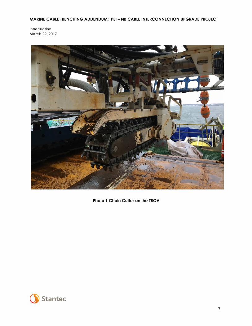
Cable Trenching in the Offshore
In water depths between -8 m LNT (NB) to -12 m LNT(PEI), the submarine cable was laid on the seafloor from the cable laying vessel prior to trenching. The trenching method identified by the cable installer used a Trenching Remotely Operated Vehicle (TROV) with a chain cutter to excavate a trench and install the cable 0.6 m below the seafloor. See Photo 1 showing the chain cutter TROV. The cables were laid in fall 2016 and the TROV subsequently initiated trenching using a chain cutter implement. During trenching, the TROV encountered material along sections of the route that was not conducive to trenching with the chain cutter; the material was either too loose and the trench collapsed, or too firm and adequate penetration could not be achieved. Subsequently the 4 km section of sand bottom (i.e., identified as “Sand Hills”) on the NB side were partially trenched (prior to vessel demobilization due to ice) using the TROV with jetting swords as it was determined that the chain cutter could not create a trench in the sand. As a result, the cable from -8 to -12 m LNT is buried only in areas where the seafloor material was favorable to trenching or jetting. The extent of cable trenching is shown graphically in Figure 2. Cable trenching in sections identified as ‘partially trenched’ (i.e., a single cutting pass has been completed but the cable has not been lowered adequately, therefore a 2nd or possibly 3rd pass using jetting or MMFE will be required) or ‘requires trenching’(i.e., no cutting, jetting or MMFE passes have been completed) in Figure 2 will be completed in spring 2017.
Inspection and Energizing
Physical inspection of the cable burial was conducted by an ROV during the cable burial process. The primary purpose of physical inspection was to ensure the cable is adequately protected and not damaged during installation. Conductivity of the conductors, and optical fiber communication line as well as resistivity of insulation within the cables has been tested on land by LS Cable Engineers; the results of these tests indicated the cables are capable of being energized. If required, the cables are currently capable of transmitting electricity.
MARINE CABLE TRENCHING ADDENDUM: PEI – NB CABLE INTERCONNECTION UPGRADE PROJECT
Introduction March 22, 2017
7
Photo 1 Chain Cutter on the TROV

MARINE CABLE TRENCHING ADDENDUM: PEI – NB CABLE INTERCONNECTION UPGRADE PROJECT
Introduction March 22, 2017
8

Cable Trenching Status as of March 2017
Figure 2121811475 - PEI-NB Interconnection - Maritime Electric Company, Limited
U:\121811475\3_drawings\3_draft_figures\mxd\pln\121811475-0135_Trench_Status.mxd
Disclaimer: This map is for illustrative purposes to support this Stantec project; questions can be directed to the issuing agency.Source: Esri, DigitalGlobe, GeoEye, Earthstar Geographics, CNES/Airbus DS, USDA, USGS, AEX, Getmapping, Aerogrid, IGN, IGP, swisstopo, and the GIS User Community, NB Power, Maritime Electric Company, Limited, Canadian Seabed Research (2014), Canadian Hydrographic Service (1972)
NAD 1983 CSRS UTM Zone 20N 121811475-0135_Trench_Status
!
!
!
!
!
!!
!
!
!
!
!
!
!
!
!
!
!
!
!
!
!
!
!
!
!
!
!
!
!
!
!
!
!
!
!
!
!
!
!
!
!!
!
!!
!
NEW BRUNSWICKCape
Tormentine
PRINCE EDWARDISLAND
Borden
Northumberland Strait
SubmarineCable #3 Submarine
Cable #4
Borden
Route10
Norri
ngRo
ad
Route 955
Highway
RiverRoad
Route 955Highway
Route10 Route
10
Chemin
Immigrant Road
Route 10
Route 955Highway
Highway10
Chem
in An
n'sAc
res Ro
ad
Route 10
Route 10
Route 960
Highway
Chemin
Bayfiel
d Road
Route 955HighwayRoute 955
Highway
Rive
rRo
ad
CheminImmigrant Road
UV16
UV1UV1
UV1
1 km2 km
3 km
4 km
5 km
6 km
7 km
8 km
9 km
10 km
11 km
12 km
13 km
14 km
15 km
16 km
17 km
1 km2 km
3 km
4 km
5 km
6 km
7 km
8 km
9 km
10 km
11 km
12 km
13 km
14 km
15 km
16 km
17 km¯
0 1 2 3 4
Kilometres
PE
Northumberland Strait
Bay of Fundy
Gulf of St. Lawrence
NB
NS
Area ofInterest
Project ComponentsStage 1 Transmission Line Construction
Bathymetry Depth ChartDatum (m)
0 - 55 - 1010 - 1515 - 2020 - 2525 - 3030 - 35
7.8 km - Completed Trenching7.1 km - Partially Trenched2.8 km - Require Trenching
7.6 km - Completed Trenching9.9 km - Require Trenching


MARINE CABLE TRENCHING ADDENDUM: PEI – NB CABLE INTERCONNECTION UPGRADE PROJECT
Options Analysis For Cable Burial in the Offshore March 22, 2017
11
2.0 OPTIONS ANALYSIS FOR CABLE BURIAL IN THE OFFSHORE
After the difficulties in meeting the required burial depth for the cable in the offshore areas that are predominately glacial till, an analysis of burial and protection methods in these particular areas was conducted by the cable contractor. Three options were reviewed:
• Depositing rock along the entire cable length • Modified chain cutter TROV then TROV with jetting swords • Modified chain cutter TROV then TROV with mini mass flow excavation (MMFE)
The rock cover would be placed using a fallpipe vessel, which is a large, self-propelled vessel that is equipped with a flexible fallpipe. The vessel's design allows the fallpipe to be lowered into the water beneath the vessel to accurately place rock released from the vessel’s holds. The fallpipe’s position can be remotely operated by the vessel operator to ensure the rock would be deposited over the cables. The rock would be sourced from a quarry in the Atlantic Region and transported by vessel to the Project Area. Quality control would be completed to verify the rock was free from clay, silt, chalk, vegetation and coal or coal residue. The process of quarrying, transportation, and laying rock over the cable would take approximately nine weeks, not including time for weather delays and equipment maintenance or repairs. This option was not considered further because of the size of the rock mounds required on top of the two cables (approximately 1 to 2 m of cover), the potential for impacts to scallop fishing gear due to the gravel mounds, the overall time required to complete the proposed works and annual inspection and maintenance requirements.
The second option was to bring a modified chain cutter TROV followed by the TROV with jetting swords capable of hydro-jetting. The chain cutter TROV would make the initial pass to loosen and partially excavate the trench material, then the TROV would be modified with two “jetting swords” or perforated pipes. The perforations or jets release pressurized seawater and are setup for different tasks. The top third of each sword fluidize the trench material, the middle third cuts the material from the trench, with the lower third jets flushing the cut material backward out of the cut and away from the trench. Figure 3 shows the TROV with Jetting Swords. This option of modified chain cutting TROV combined with the use of jetting swords in the glacial till is not the preferred option for trenching and burial in the glacial till but may be used where necessary. The determination was based on the results of the jetting work that was completed in December 2016 in the sand hill areas on the NB side of the Northumberland Strait.

MARINE CABLE TRENCHING ADDENDUM: PEI – NB CABLE INTERCONNECTION UPGRADE PROJECT
Options Analysis For Cable Burial in the Offshore March 22, 2017
12
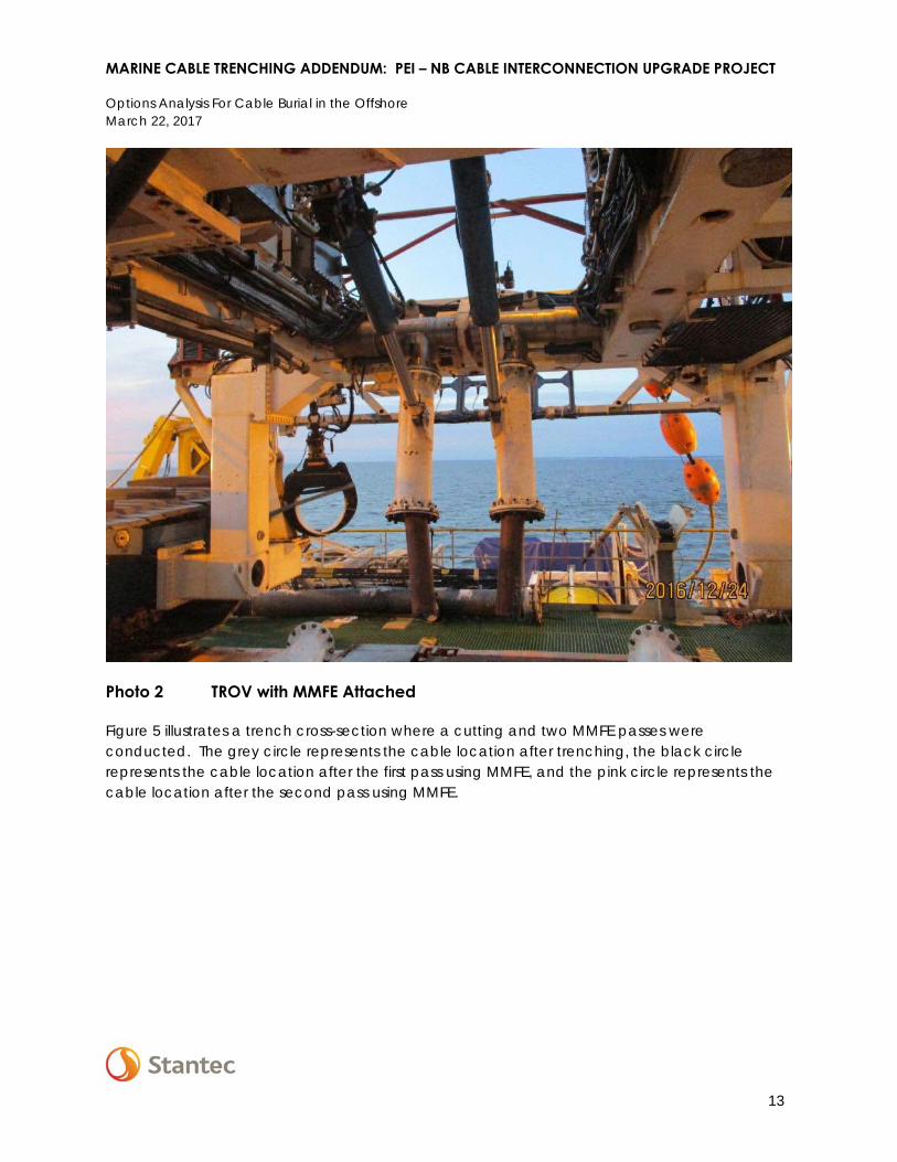
The third option was to bring a modified chain cutter TROV followed by TROV with a mini mass flow excavator (MMFE). The chain cutter TROV would make the initial pass to loosen and partially excavate the trench material. The MMFE would then make a maximum of two jetting passes, releasing high pressure seawater on either side of the cable. This release of seawater is directed down on both sides of the cable to break up the soil surface to fluidize the area and allow the cable to sink in place. Photo 2 shows the TROV in the MMFE mode with two pipes pointing down and set at a distance to be on either side of the cable.
Figure 3 TROV with Jetting Swords
The proposed MMFE pass would increase the trench dimensions from the cutting pass. A test was carried out in December 2016 to determine if the MMFE process would bury the cable to the desired depth of 0.6 m and to identify the size of the trench that would be created, if any, from the MMFE. Figure 4 illustrates two trench cross-sections, with a) representing a location where only the cutting pass was conducted, and b) representing a location where a cutting and a MMFE pass was conducted. The black circle in the figure represents the cable location after one cutting pass and the pink circle represents the cable location after the MMFE pass.
MARINE CABLE TRENCHING ADDENDUM: PEI – NB CABLE INTERCONNECTION UPGRADE PROJECT
Options Analysis For Cable Burial in the Offshore March 22, 2017
13
Photo 2 TROV with MMFE Attached
Figure 5 illustrates a trench cross-section where a cutting and two MMFE passes were conducted. The grey circle represents the cable location after trenching, the black circle represents the cable location after the first pass using MMFE, and the pink circle represents the cable location after the second pass using MMFE.

MARINE CABLE TRENCHING ADDENDUM: PEI – NB CABLE INTERCONNECTION UPGRADE PROJECT
Options Analysis For Cable Burial in the Offshore March 22, 2017
14

MARINE CABLE TRENCHING ADDENDUM: PEI – NB CABLE INTERCONNECTION UPGRADE PROJECT
Options Analysis For Cable Burial in the Offshore March 22, 2017
15
Figure 4 Cable Burial Depth Using One Cutting Pass (a) and a Subsequent MFFE Pass (b) [all distances in metres].
Initial Cutting Pass
Subsequent MMFE Pass
a)
b)

MARINE CABLE TRENCHING ADDENDUM: PEI – NB CABLE INTERCONNECTION UPGRADE PROJECT
Options Analysis For Cable Burial in the Offshore March 22, 2017
16
Figure 5 Cable burial depth using one cutting pass (grey circle is the cable), a subsequent pass with MMFE (black circle is the cable), and a second pass with MMFE (pink circle is the cable).

MARINE CABLE TRENCHING ADDENDUM: PEI – NB CABLE INTERCONNECTION UPGRADE PROJECT
Options Analysis For Cable Burial in the Offshore March 22, 2017
17
A summary of the TROV with jetting swords and the chain cutter TROV with MMFE trenching completed in December 2016 is provided in Table 1.
Table 1 Summary of the TROV with Jetting Swords and the Chain Cutter TROV with MMFE Trenching Conducted in December 2016
Single Jetting Swords Pass
Second Jetting Swords Pass
Single Chain Cutter TROV Pass and
Single MMFE Pass Second MMFE Pass
• After single jetting pass, the cable is lowered to a burial depth of approx. 0.4 to 0.6 m.
• Almost no material cover remains on top of the cable.
• The width of the trench at the surface of the seabed is approx. 2 to 3 m.
• After second jetting pass, the cable is lowered to a burial depth of approx. 1.3 m.
• A layer of 0.4 to 0.5 m of material cover remains on top the cable.
• The width of the trench at the surface of the seabed is approx. 2 to 3 m.
• After single TROV and a single MMFE pass, the cable is lowered to a burial depth of approx. 0.6 m.
• A material cover between 0 and 0.6 m remains on top of the cable.
• The width of the trench at the surface of the seabed is 0 to approx. 2 m.
• After a second MMFE pass, the cable is lowered to a burial depth of about 0.6 to 1.3 m.
• A material cover between 0 and 1.3 m remains on top of the cable.
• The width of the trench at the surface of the seabed is 0 to approx. 3 m.
The MMFE method, overall, results in more coverage and depth than the jetting swords method and is therefore the preferred option to be used in conjunction with the TROV in spring 2017. In addition, the impacts on the trench opening are anticipated to be less using the MMFE method, as the material would remain in the trench rather than being blown out when using the jetting sword method.
2.1 ADDITIONAL TROV MODIFICATIONS
Based on the TROV operation completed in November and December 2016, modifications have been made to the TROV to help expedite spring season trenching and will include the following:
• teeth on the cutting chain have been modified to allow for quicker replacement reducing downtime for maintenance
• additional plates (I.e., Grouser plates) are being welded perpendicular to the cutting chain to improve the removal of loose material being cut with the cutting chain
• optimized water flow through the discharge hoses allowing for easier removal of the cut material from the trench
• improved design for the jetting swords for second pass and remaining cables to be buried in the sand hill areas

MARINE CABLE TRENCHING ADDENDUM: PEI – NB CABLE INTERCONNECTION UPGRADE PROJECT
Future Project Activities for Spring 2017 March 22, 2017
18
3.0 FUTURE PROJECT ACTIVITIES FOR SPRING 2017
A general overview of the construction activities to be undertaken is presented in this section. The description includes the cable trenching, burial and backfilling activities to occur in 2017. These proposed trenching activities with the modified chain cutter TROV with additional passes over the trenched cables using the MMFE to achieve the required burial depth of the cables are a change to the original trenching scope outlined in the Marine Supplemental No. 2 submitted in February 2016.
3.1 TWIN SUBMARINE CABLES
Trenching, burial and backfilling activities will begin as soon as ice-out in spring 2017 following government approval and the receipt of all necessary permits and authorizations. The following is a brief description of construction activities that are proposed for the burial of the submarine cables. These activities will be managed by MECL in accordance with permit/approval conditions and the Project’s Environmental Protection Plan.
3.1.1 Trenching and Burial (Offshore)
In mid-March 2017, the cable installation company is planning to complete sea trials on the TROV using the jetting sword modifications as well as the modified chain cutter TROV off the coast of Nova Scotia (NS). Once ice has migrated out of the Project Area, the cable installation company will mobilize from Halifax, NS and start trenching operation immediately.
The remaining sand hills area will be trenched first using the modified jetting swords. To help reduce the amount of time on site using the modified TROV and MMFE, the cable installer will continue into the glacial till area using the modified jetting swords until the till begins to push the swords up, thus reducing the depth of the cut. This will reduce the total amount of area that will require multiple passes with the modified TROV and MMFE. Once the swords can no longer maintain the necessary cable burial depth, the MMFE method will be used to jet the cable in place in the area that was trenched in the fall, followed by cutting the remaining areas and then switching back to MMFE. A second pass will be conducted, as required, to obtain the desired cable depth.
The initial Project Description (Stantec 2015a) indicated the trench width will range from 1 to 5 m. This range was reduced in the Marine Supplemental Report (Stantec 2016) and Disposal at Sea permit application to Environment Canada as the trenching method was identified following completion of the EIS. In the Marine Supplemental No. 2 and subsequent Disposal at Sea permit application, the trench was predicted to be 0.35 m wide, which was the width of the trench created by the chain cutter implement.

MARINE CABLE TRENCHING ADDENDUM: PEI – NB CABLE INTERCONNECTION UPGRADE PROJECT
Future Project Activities for Spring 2017 March 22, 2017
19
The trench dimensions after the completion of the pass using MMFE are approximately 0 to 3 m, with a cable depth of about 0.6 to 1.3 m. The material cover on top of the cable would be between 0 and 1.3 m, with 0 m cover indicating no material remains on top of the cable after the MMFE pass. The trench dimensions after the completion of the MMFE passes are within the initial EIS predictions (i.e., width of 1 to 5 m), though larger than that described in the Marine Supplemental No. 2 and Disposal at Sea permit application (i.e., 0.35 m wide).
3.1.2 Backfilling (Nearshore)
Backfilling and burial of the cable in the nearshore areas (<-8 m LNT in NB and <-12 m LNT in PEI) was partially completed in fall 2016. Backfilling of the cable trench from 0 to -3 m LNT has been completed in PEI and from 0 to -3 m LNT in NB. Gravel protection was laid in both PEI from -3 to -12 m LNT (a final survey was not completed on cable 3 in PEI as the ice formed before this could be completed. It is expected that when work resumes in the Spring there will be enough gravel/sediment cover to begin backfilling operations on cable 3 but there is a possibility that additional gravel protection will be required. This area will be surveyed after ice-out and a determination will be made at that time) and NB from -3 to -8 m LNT in the fall 2016. Backfilling of the trench from -3 to -12 m LNT in PEI will not be undertaken. Backfilling with the excavated material will be completed in the NB nearshore waters from -3 m to -8 m LNT (approx. 1,450 m/cable) in spring 2017. To complete backfilling operations, the cable contractor is proposing to use barge-mounted clamshell dredges to move the sidecast material excavated from the trench back into the trench.
3.1.3 Backfilling (Offshore)
Cable burial in the offshore will be completed as necessary using a combination of the modified chain cutter TROV and MMFE. Following post-trenching surveys, portions of the trench which did not naturally slump or infill to protect the cable will be backfilled using material from the trench sidewall. This will be conducted, if necessary, by placing water jets on either side of the trench (i.e., each jet would be 1.9 m from the centerline of the original trench) and directing water flow outside the trenched area to destabilize the wall and have material collapse into the trench. Figure 6 presents this backfilling method with water jet placement and cut sections collapsing into the trench. The result is a backfilled trench similar in shape to that illustrated in Figure 4 (b).

MARINE CABLE TRENCHING ADDENDUM: PEI – NB CABLE INTERCONNECTION UPGRADE PROJECT
Future Project Activities for Spring 2017 March 22, 2017
20
Figure 6 Alternative Backfill Methodology Once Cable is to Depth in the Trench
3.1.4 Post-trenching Surveys
Following the nearshore and offshore backfilling activities, post-trenching surveys will be completed along the entire route using an ROV to ensure cable burial. The TSS 350 Cable Survey System mounted to the ROV will be used to provide accurate survey data, verifying the location and burial status of the cable. Any sections with incomplete burial will be noted and identified. Depending on the extent of cable exposure, additional MMFE passes or backfilling operations as provided in Section 3.1.3 will be implemented to increase coverage, and/or additional measures may be conducted for cable burial such as the use of concrete mats in areas were bedrock was encountered above a trench depth of 0.6 m.
3.2 PROJECT SCHEDULE
The second round of cable trenching and backfilling is proposed to begin mid-March 2017, or as soon as the Strait is clear of ice and following the receipt of all necessary permits and authorizations. The best-case scenario proposes that trenching begins mid-March and is anticipated to take 26 days, not including time for weather delays and equipment maintenance or repairs. The proposed start date after ice-out was selected to avoid as much as possible the May scallop fishing season in Scallop Fishing Area (SFA 22). Refer to Appendix A for the cable installers schedule of works for 2017. Depending on the ice-out date, there is also the potential

MARINE CABLE TRENCHING ADDENDUM: PEI – NB CABLE INTERCONNECTION UPGRADE PROJECT
Future Project Activities for Spring 2017 March 22, 2017
21
for the cable burial activities to interact with the groundfish and herring fisheries which typically start in April. If ice leaves later in April, the cable burial activities could interact with Scallop fishing season. In addition, trenching activities could extend into May and June due to weather, general equipment maintenance and repairs or even slower than expected progress. The actual start dates for trenching and backfilling may need to be adjusted based on ice presence or receipt of regulatory permits and authorizations. Current ice modeling predictions show that the ice will be gone from the strait in mid to late March.
3.3 INTERACTIONS WITH COMMERCIAL FISHERIES
The current schedule may result in project interaction with commercial fisheries. Currently, with the cable partially buried on the seafloor, a potential fisheries exclusion zone of 500 m on either side of the cables maybe proposed for both sides of the cable and around the cable burial vessel. Figure 7 presents the currently proposed exclusion zone within SFA 22. This fishery exclusion zone would remain in place until the cable is buried to reduce the risk for entanglement or damage to commercial fishing gear or the cable. Following verification of cable burial after the post-trenching surveys, the exclusion zone would be lifted. Information meetings with local fishers and rights holders will be conducted in the first few weeks of March. The information presented in this addendum is the information that will be shared with the fishers and rights holders.
The jetting/MMFE TROV has the potential to increase localized TSS concentrations near the cable burial operations. Model predictions of sediment plumes from jetting/MMFE operations carried out for similar projects are included in Table 2. The distance a sediment plume travels is dependent on water depth, currents, sea state, and ambient total suspended solid (TSS) concentration and turbidity. Based on modelling jet trenching activities in seabeds with different substrate types (ASA 2006; ASA 2011; Jiang et al. 2007; Leeper 2005; TRC 2011) that are summarized in Table 2, the suspended sediment plumes from jetting/MMFE in the Northumberland Strait are more similar to those for a material containing medium to coarse sand because of the glacial till in which trenching will occur. The substrate sampled in the deeper waters (>20 m) of Northumberland Strait contained 54% to 85% sand and 10% to 34% gravel, with silt or clay generally less than 5% (Stantec 2015b). Therefore, the TSS is likely to range from 4 to 35 mg/L about 50 m from the jetting activity (Table 2). The background TSS concentration in the Northumberland Strait can range from 2 to 19 mg/L, and increase to 14 to 27 mg/L after wind and precipitation events (Stantec 2015b). Therefore, jetting and the resulting increase in TSS is likely limited to only a localized effect.

MARINE CABLE TRENCHING ADDENDUM: PEI – NB CABLE INTERCONNECTION UPGRADE PROJECT
Future Project Activities for Spring 2017 March 22, 2017
22
Table 2 Predicted Range of TSS Associated with Jet Trenching
Activity Trenching Rate (m/hour)
Trench Volume (m3/m) Material TSS Range at 50 m from
source(mg/L)
Jet Trenching 91 3.0 50% coarse sand 50% fine sand
<50 mg/L, peaks at 500 mg/L
Jet Trenching 198 0.72 fine sand and silt 100 to 200 mg/L, peaks at 400 mg/L
Jet Trenching 300 1.0 fine to medium sand 500 to 1,000 mg/L
peaks at 1,800 mg/L
0.2 fine to medium sand 40 to 100 mg/L peaks at 300 mg/L
Jet Trenching undefined 1.54 medium to coarse sand
4 to 35 mg/L peaks at 310 mg/L
Jet Trenching 100 2.0 undefined 200 to 750 mg/L peaks at 1,200 mg/L
Based on data from: ASA 2006; ASA 2011; Jiang et al. 2007; Leeper 2005; TRC 2011.
Excavation of soft sediment in the marine environment will infill naturally over time based on slumping, the movement of the seabed (bedload transport), and deposition from naturally occurring suspended sediment and from re-suspended bottom sediments. To decrease the time the trenches remain open after laying the cable, the cable contractor may backfill the offshore trenches using water jets if the post-trenching survey shows large areas of exposed cable in the trenches. For the offshore areas where the modified chain cutter TROV and MMFE will be used, the trench will be left to infill naturally if the post survey shows acceptable levels of material on top of the trenched cables. To estimate the time required to infill the remaining trench, a sediment transport model (Sedtrans05) was used to calculate total bedload transport per hour per metre of trench. Infilling time was calculated for two scenarios, assuming trench infilling would come entirely from predominately bedload movement compared to other infilling processes noted above. The first scenario used the predicted maximum dimensions of the trench after the MMFE has completed two passes (1.3 m deep and 3.0 m wide). The second scenario used the predicted maximum dimensions of the trench after the MMFE has completed one pass (0.6 m deep and 2 m wide).

Proposed Scallop Exclusion Zone
Figure 7121811475 - PEI-NB Interconnection - Maritime Electric Company, Limited
U:\121811475\3_drawings\3_draft_figures\mxd\pln\121811475-0136_Fishing_Restriction_Zone.mxd
Disclaimer: This map is for illustrative purposes to support this Stantec project; questions can be directed to the issuing agency.Source: Esri, DigitalGlobe, GeoEye, Earthstar Geographics, CNES/Airbus DS, USDA, USGS, AEX, Getmapping, Aerogrid, IGN, IGP, swisstopo, and the GIS User Community, NB Power, Maritime Electric Company, Limited, Canadian Seabed Research (2014), Canadian Hydrographic Service (1972)
NAD 1983 CSRS UTM Zone 20N 121811475-0136_Fishing_Restriction_Zone
!
!
!
!
!
!
!
!
!
!
!
!
!
!
!
!
!
!
!
!
!
!
!
!
!
!
!
!
!
!
!
!
!
!
!
!
!
!
!
!
!
!
!
!
!
!
!
!
!
!
!
!
!
!
!
!
!
!
!
!
!
!
!
!
!
!
!
!
!
!
!
!
!
!
!
!
!
!
!
!
!
!
!
!
!
!
!
!
!
!
!
!
!
!
!
!
!
!
Charlottetown
Saint-Joseph
Douglastow n
Pugw ash
MiddleSackville
Saint-Anselme
ChapmanCorner
Chatham
Sackville
Rogersville
Kensington
Saint-Antoine
Riverview
Dieppe
ShediacBridge
Nelson-Miramichi
Shediac
Bouctouche
Keppoch
Petitcodiac
Miscouche
NorthRustico
Har risville
Tignish
Lakeville
ChathamHead
EastAmherst
Manuels
Cocagne
Moncton
Hillsborough
Robichaud
Lakeburn
SlemonPark
Big Cove
Richibucto
Memr amcook
Buctouche-Sud
Scoudouc
Grande-Aldouane
Summer side
Amherst
Cornwall
MagneticHill
Cap-Pele
Dorchester
Saint-Louisde Kent
St.Eleanor s
Highfield
HillsboroughPark
O'Leary
Salisbury
Rexton
Alberton
Southport
ReadsCorner
NorthRiver
Bunbury
Pointe-du-C hêne
Low erCoverdale
Hildegar de
MiltonvalePark
Borden
Miramichi
UV2
UV1
UV1
UV112
UV126
UV1
UV118
UV1
UV1
UV1UV1
UV134
UV1
UV1
UV2
UV2
UV117
UV1
UV115
UV11
UV1
UV114
UV126
UV2
UV1
UV1
UV6
UV150
UV1
UV16
UV133
UV6
UV1
UV16
UV15
UV128
UV106
UV1
UV112
UV1
UV112
UV1A
UV1
UV2
UV114
UV8
UV132
UV1
UV106
UV1
UV116
UV2
UV8
UV15
UV3
UV2
UV15
UV2
UV11
UV2
UV2
UV2
UV2
UV1A
UV106
UV15
UV104
UV104
UV133
UV1
UV15
UV1
UV11
UV142
UV134
MurrayBeach
ParleeBeach
TheRocks
¯
0 5 10 15 20 25
Kilometres
PE
Northumberland Strait
Bay of Fundy
Gulf of St. Lawrence
NB
NS
Area ofInterest
Proposed Fishing Restriction Zone (1200 m Wide Corridor )Scallop Fishing Area 22 /Lobster Fishing Area 25
Project Components in theNorthumberland Strait
Submarine Cable #3Submarine Cable #4
Project ComponentsStage 1 Transmission Line ConstructionStage 2 Transmission Line Construction
!Borden
UV16
UV1


MARINE CABLE TRENCHING ADDENDUM: PEI – NB CABLE INTERCONNECTION UPGRADE PROJECT
Future Project Activities for Spring 2017 March 22, 2017
25
Sediment transport rates are presented in Table 3 as the resulting volume of sediment moved per hour per linear metre of trench. The sediment transport rates are listed for each station using the baseline currents and sediment grain size obtained during the EIA (Stantec 2015b) and the maximum predicted currents from the Abegweit Passage Current Tables for April/May 2017 (CHS 2017).
Table 3 Sediment Transport Rates
Sediment Transport Station A
Coordinates (NAD 83) Water Depth
(m)
Baseline Currents (Nov. 2015)B,C
Max Predicted CurrentsC,D
Sediment Transport (m3/hr/m)
Sediment Transport (m3/hr/m) Easting (m) Northing (m)
S8 (NB) 441821 5111396 13.9 0.0047 0.0738
S7 442192 5112513 19.4 0.0079 0.0620
S6 442564 5113626 27.6 <0.0004 0.0378
S5 443014 5115010 25.7 <0.0004 0.0324
S4 443510 5116505 23.5 <0.0004 0.0477
S3 445006 5117524 23.1 <0.0004 0.0482
S2 (PEI) 446101 5119487 16.4 0.0018 0.0605 Notes: A S2 is close to PEI, S8 is close to NB and the remaining location are along the cable route in the Northumberland
Strait. B Baseline currents collected during a flooding tide between Borden and Cape Tourmentine C Wave height and period taken from MSC50 Averages for April/May (Grid Point 009946) D Maximum predicted currents from Abegweit Passage Current Charts (CHS 2017)
Using the bedload transport rates to estimate sediment transport, the completely void (worst-case scenario modified chain cutter TROV with two passes of the MMFE) trench (1.3 m deep x 3 m wide) is estimated to infill within three to six days under sustained maximum currents and three weeks to three months with sustained baseline (tidal) currents. In deeper water depths of the cable with no predicted bedload transport (<0.0004 m3/hr/m), a time to infill cannot be estimated. The timelines for the partial trench infilling (Scenario 2) ranged from one day to one month under sustained maximum and baseline tidal currents, respectively, and taking into account tidal currents are at their peak for only a couple hours per day. A realistic time to infill the trench using a combination of the calculated results is likely in the range of several weeks to months. Localized bathymetry and geology conditions may also reduce or increase these infilling times.
These results are comparable to the findings in the 2014 Marine Geophysical Survey Report (CSR 2015) which assessed ice scour (the trenches left by ice movement) within the Northumberland Strait. The report indicated that 75% of ice scour in sandy substrate was completely removed within 6 months and two thirds of the ice scour in gravel substrate were either severely infilled or completely removed in the same period of time (CSR 2015).

MARINE CABLE TRENCHING ADDENDUM: PEI – NB CABLE INTERCONNECTION UPGRADE PROJECT
Monitoring March 22, 2017
26
4.0 MONITORING
Prior to commencing cable trenching and burial in 2017, MECL is proposing to conduct an underwater survey to visually identify the trenching completed in 2016. This survey will serve to further the understanding of sediment accumulation and trench infilling in the Project Area. Visual surveys will be conducted using divers in the nearshore areas and the partially trenched portion of Cable #4 specifically to identify the amount of infilling that occurred from January to March 2017.
During backfilling operations in the nearshore New Brunswick between -3 m and -8 m LNT, TSS and turbidity samples will continue to be collected as per the sampling program initiated in 2016. During trenching and backfilling operations in 2016, periodic TSS and turbidity samples were collected at distances of 100, 200, 500, 1000 and 1500 m east and west of the excavation equipment.

MARINE CABLE TRENCHING ADDENDUM: PEI – NB CABLE INTERCONNECTION UPGRADE PROJECT
References March 22, 2017
27
5.0 REFERENCES
Applied Science Associates (ASA), 2006. Simulation of Sediment Transport and Deposition from Cable Burial Operations for the Alternative Site of the Cape Wind Energy Project.
Applied Science Associates (ASA), 2011. Results of Sediment Dispersion Analysis for the Mid Atlantic Power Pathway: Chesapeake Bay Crossing – Jet Plow Embedment.
Canadian Hydrographic Service (CHS), 2017. Canadian Tide and Current Tables. Accessed at: http://www.charts.gc.ca/publications/tables-eng.asp on February 9, 2017.
Canadian Seabed Research (CSR), 2015. Northumberland Strait Cable Route Assessment 2014 Marine Geophysical Survey.
Jiang, J., D.B Fissel, K. Borg, 2007. Sediment Plume and Deposition Modeling of Removal and Installation of Underwater Electrical Cables on Roberts Bank, Strait of Georgia, British Columbia, Canada.
Leeper, P.C. 2005. Monitoring of Suspended Solids: Fox Island Electric Cooperative Inc. Submarine Cable Installation Clam Cove to North Haven Island Penobscot Bay, Maine.
McGregor GeoScience Limited, 2015. Survey and Geotechnical Report NB-PEI Interconnector.
Stantec Consulting Ltd., 2015a. PEI-NB Cable Interconnection Upgrade Project – VOLUME 1 Project Description.
Stantec Consulting Ltd., 2015b. PEI-NB Cable Interconnection Upgrade Project – VOLUME 3 The Northumberland Strait.
Stantec Consulting Ltd.,2016. PEI-NB Cable Interconnection Upgrade Project EIA: Marine Supplemental Report No. 2.
TRC Environmental Corporation, 2011. Sediment Dispersion and Deposition Modeling Study for Vermont Green Lin Submarine Cable.


MARINE CABLE TRENCHING ADDENDUM: PEI – NB CABLE INTERCONNECTION UPGRADE PROJECT
March 22, 2017
CABLE INSTALLERS SCHEDULE OF
WORKS FOR 2017


ID Task Name Duration Start Finish Predecessors Resource
Names
% Complete
1 ICE SEASON 2017 97.98 days 08/01/2017 15/04/2017 68%
2 Onshore and Nearshore Works 10 days 02/01/2017 12/01/2017 55%
3 Onshore Works 10 days 02/01/2017 12/01/2017 85%
4 Rock Revetment Installation 48 days 09/01/2017 26/02/2017 85%
5 Rock Revetment PEI 29 days 09/01/2017 07/02/2017 100%
6 Rock Revetment NB 5 days 21/02/2017 26/02/2017 0%
7 Nearshore Works 28 days 15/04/2017 13/05/2017 21%
8 Gravel Protection Installation 7.98 days 15/04/2017 22/04/2017 21%
9 Gravel Protection PEI 5 days 15/04/2017 20/04/2017 1 90%
10 Gravel Protection NB 2 days 20/04/2017 22/04/2017 9 90%
11 Weather provision Gravel Protection Installation (Waiting
feedback of Ocean)
0%
12 Backfilling Works 21 days 22/03/2017 12/04/2017 0%
13 Backfilling PEI 15 days 22/04/2017 07/05/2017 10 0%
14 Backfilling NB 6 days 07/05/2017 13/05/2017 13 0%
15 Weather provision Backfilling Works (Waiting feedback
of Ocean)
0%
16 Post-Lay Trenching Works 120.11 days 12/01/2017 12/05/2017 2%
17 Standby TSV Spread (UTV1200) during Ice Season 68 days 12/01/2017 21/03/2017 1%
18 Sailing from Site to Halifax 2 days 12/01/2017 14/01/2017 0%
19 Standby for Ice / Trials in Halifax 64.98 days 14/01/2017 19/03/2017 18 0%
20 Sailing from Halifax to Site 2 days 19/03/2017 21/03/2017 19 50%
21 Offshore sections (between -12m LAT lines) 27.11 days 01/04/2017 28/04/2017 4%
22 Trenching Works 20.06 days 01/04/2017 21/04/2017 6%
23 Cable Route 4 (approx. 2,500m) - Cutting 1.86 days 01/04/2017 02/04/2017 20 33%
24 Cable Route 3 (approx. 10,000m) - Cutting 6.39 days 02/04/2017 09/04/2017 23 0%
25 Wear and Tear Provision Cutting Works 3 days 09/04/2017 12/04/2017 24 0%
26 Cable Route 4 (approx. 10,000m) - Jetting short swords or
MFE after cutting
3.56 days 12/04/2017 15/04/2017 25 17%
27 Cable Route 3 (approx. 10,000m) - Jetting short swords or
MFE after cutting
3.68 days 15/04/2017 19/04/2017 26 0%
28 Wear and Tear Provision Jetting Works 0.83 days 19/04/2017 20/04/2017 27 0%
29 Environmental Downtime Provision Trenching Works 0.99 days 20/04/2017 21/04/2017 28 0%
30 Post Trench Survey 7.05 days 21/04/2017 28/04/2017 0%
31 Cable Route 3 (approx. 11,000m) 2.47 days 21/04/2017 23/04/2017 29 0%
32 Cable Route 4 (approx. 11,000m) 2.58 days 23/04/2017 26/04/2017 31 0%
33 Downtime Provision Post Trench Survey (environment,
processing)
2 days 26/04/2017 28/04/2017 32 0%
34 Demobilization TSV Spread (UTV1200) 14 days 24/04/2017 08/05/2017 0%
35 Demobilization TSV Spread 14 days 28/04/2017 12/05/2017 33 0%
36 0%
Jan Feb Mar Apr May Jun Jul
Qtr 1, 2017 Qtr 2, 2017
Project Schedule: PEI-NB Interconnector Cables