Marine and Petroleum Geology · 2019-10-09 · L.LeiandJ.C.Santamarina Marine and Petroleum Geology...
13
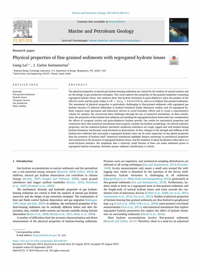
Contents lists available at ScienceDirect Marine and Petroleum Geology journal homepage: www.elsevier.com/locate/marpetgeo Research paper Physical properties of fine-grained sediments with segregated hydrate lenses Liang Lei a,∗ , J. Carlos Santamarina b a National Energy Technology Laboratory, U.S. Department of Energy, Morgantown, WV, 26507, USA b Earth Science and Engineering, KAUST, Thuwal, Saudi Arabia ARTICLE INFO Keywords: Fine-grained sediments Hydrate lenses Cryogenic suction Gas production Slope stability ABSTRACT The physical properties of natural gas hydrate-bearing sediments are critical for the analysis of natural systems and for the design of gas production strategies. This work explores the properties of fine-grained sediments containing segregated hydrate lenses. Our analyses show that hydrate formation is grain-displacive when the product of the effective stress and the grain radius is σ′R < 2πΓ hw ≈ 0.2-to-0.3 N/m, such as in shallow fine-grained sediments. The assessment of physical properties is particularly challenging in fine-grained sediments with segregated gas hydrate because (1) inherent difficulties in hydrate formation hinder laboratory studies, and (2) segregated hy- drate requires large specimens and laboratory devices to avoid boundary effects and to create a representative volume for analysis. We circumvent these challenges through the use of numerical simulations. In these simula- tions, the properties of the hydrate-free sediment surrounding the segregated hydrate lenses take into consideration the effects of cryogenic suction and grain-displacive hydrate growth. Our results for mechanical properties and conduction show that numerical simulations must properly consider the hydrate morphology, the altered sediment properties, and the sediment-hydrate interfacial conditions (interfaces are rough, jagged and well bonded during hydrate formation, but become weak-frictional on dissociation). In fact, changes in the strength and stiffness of the hydrate-free sediment that surrounds a segregated hydrate mass can be more important on the global properties than the presence of hydrate itself. Numerical simulations highlight distinct anisotropy in mechanical properties and conduction in the presence of segregated hydrate lenses, and the tendency to shear localization when there is a weak-frictional interface. We emphasize that a relatively small fraction of fines can make sediments prone to segregated hydrate formation, therefore proper sediment classification is critical. 1. Introduction Gas hydrate accumulations in marine sediments and the permafrost are a vast potential energy resource (Boswell, 2009; Collett, 2002). In addition, natural gas hydrate dissociation can contribute to climate change (Archer, 2007; Ruppel and Pohlman, 2008), cause ground subsidence and trigger seafloor landslides (Grozic, 2010; Hornbach et al., 2007; Kvalstad et al., 2005). The mechanical, thermal, and hydraulic properties of gas hydrate- bearing sediments are critical to both the analysis of natural gas hydrate reservoirs and the design of gas extraction strategies. The transmission of heat and fluids control hydrate dissociation and gas migration (Makogon, 1997; Sloan and Koh, 2007). In addition, the mechanical properties of hy- drate-bearing sediments can be markedly different before and after dis- sociation, thus, initially stable systems can become unstable during hydrate dissociation (Kwon et al., 2008; Moridis et al., 2011; Waite et al., 2009). A number of difficulties limit the accurate characterization and direct measurement of the physical properties of hydrate-bearing sediments. Pressure cores are expensive, and mechanical sampling disturbances are inherent to all coring techniques (Dai and Santamarina, 2014; Hvorslev, 1949). In-situ measurements only assess a small area around the well- logging tool, which is disturbed by the insertion of the device itself. Laboratory hydrate formation is challenging in all sediments (Spangenberg et al., 2005; Waite and Spangenberg, 2013), particularly in fine-grained sediments (Lei and Santamarina, 2018). Furthermore, hy- drate tends to form as a segregated mass in fine-grained sediments and the length-scale of natural hydrate lenses and veins exceeds the cen- timeter-scale of laboratory devices (Collett et al., 2008; Lee et al., 2013; Yamamoton et al., 2012; Yun et al., 2011). Studies of physical properties of hydrate-bearing fine-grained sediments are thus limited to geophysical logs, e.g. (Cook et al., 2008; Tréhu et al., 2004), some pressure core based measurements (Yun et al., 2011), and numerical simulations that explore segregated hydrate geometries but neglect the effect of hydrate forma- tion on surrounding sediments (Ghosh et al., 2010). Most hydrate accumulations involve fine-grained sediments (Boswell and Collett, 2011). Therefore, there is a need for an enhanced https://doi.org/10.1016/j.marpetgeo.2019.08.053 Received 19 February 2019; Received in revised form 24 August 2019; Accepted 30 August 2019 ∗ Corresponding author. E-mail address: [email protected] (L. Lei). Marine and Petroleum Geology 109 (2019) 899–911 Available online 03 September 2019 0264-8172/ © 2019 Elsevier Ltd. All rights reserved. T
Transcript of Marine and Petroleum Geology · 2019-10-09 · L.LeiandJ.C.Santamarina Marine and Petroleum Geology...
Contents lists available at ScienceDirect
Marine and Petroleum Geology
journal homepage: www.elsevier.com/locate/marpetgeo
Research paper
Physical properties of fine-grained sediments with segregated hydrate lensesLiang Leia,∗, J. Carlos Santamarinab
a National Energy Technology Laboratory, U.S. Department of Energy, Morgantown, WV, 26507, USAb Earth Science and Engineering, KAUST, Thuwal, Saudi Arabia
A R T I C L E I N F O
Keywords:Fine-grained sedimentsHydrate lensesCryogenic suctionGas productionSlope stability
A B S T R A C T
The physical properties of natural gas hydrate-bearing sediments are critical for the analysis of natural systems andfor the design of gas production strategies. This work explores the properties of fine-grained sediments containingsegregated hydrate lenses. Our analyses show that hydrate formation is grain-displacive when the product of theeffective stress and the grain radius is σ′R < 2πΓhw ≈ 0.2-to-0.3 N/m, such as in shallow fine-grained sediments.The assessment of physical properties is particularly challenging in fine-grained sediments with segregated gashydrate because (1) inherent difficulties in hydrate formation hinder laboratory studies, and (2) segregated hy-drate requires large specimens and laboratory devices to avoid boundary effects and to create a representativevolume for analysis. We circumvent these challenges through the use of numerical simulations. In these simula-tions, the properties of the hydrate-free sediment surrounding the segregated hydrate lenses take into considerationthe effects of cryogenic suction and grain-displacive hydrate growth. Our results for mechanical properties andconduction show that numerical simulations must properly consider the hydrate morphology, the altered sedimentproperties, and the sediment-hydrate interfacial conditions (interfaces are rough, jagged and well bonded duringhydrate formation, but become weak-frictional on dissociation). In fact, changes in the strength and stiffness of thehydrate-free sediment that surrounds a segregated hydrate mass can be more important on the global propertiesthan the presence of hydrate itself. Numerical simulations highlight distinct anisotropy in mechanical propertiesand conduction in the presence of segregated hydrate lenses, and the tendency to shear localization when there is aweak-frictional interface. We emphasize that a relatively small fraction of fines can make sediments prone tosegregated hydrate formation, therefore proper sediment classification is critical.
1. Introduction
Gas hydrate accumulations in marine sediments and the permafrostare a vast potential energy resource (Boswell, 2009; Collett, 2002). Inaddition, natural gas hydrate dissociation can contribute to climatechange (Archer, 2007; Ruppel and Pohlman, 2008), cause groundsubsidence and trigger seafloor landslides (Grozic, 2010; Hornbachet al., 2007; Kvalstad et al., 2005).
The mechanical, thermal, and hydraulic properties of gas hydrate-bearing sediments are critical to both the analysis of natural gas hydratereservoirs and the design of gas extraction strategies. The transmission ofheat and fluids control hydrate dissociation and gas migration (Makogon,1997; Sloan and Koh, 2007). In addition, the mechanical properties of hy-drate-bearing sediments can be markedly different before and after dis-sociation, thus, initially stable systems can become unstable during hydratedissociation (Kwon et al., 2008; Moridis et al., 2011; Waite et al., 2009).
A number of difficulties limit the accurate characterization and directmeasurement of the physical properties of hydrate-bearing sediments.
Pressure cores are expensive, and mechanical sampling disturbances areinherent to all coring techniques (Dai and Santamarina, 2014; Hvorslev,1949). In-situ measurements only assess a small area around the well-logging tool, which is disturbed by the insertion of the device itself.Laboratory hydrate formation is challenging in all sediments(Spangenberg et al., 2005; Waite and Spangenberg, 2013), particularly infine-grained sediments (Lei and Santamarina, 2018). Furthermore, hy-drate tends to form as a segregated mass in fine-grained sediments andthe length-scale of natural hydrate lenses and veins exceeds the cen-timeter-scale of laboratory devices (Collett et al., 2008; Lee et al., 2013;Yamamoton et al., 2012; Yun et al., 2011). Studies of physical propertiesof hydrate-bearing fine-grained sediments are thus limited to geophysicallogs, e.g. (Cook et al., 2008; Tréhu et al., 2004), some pressure core basedmeasurements (Yun et al., 2011), and numerical simulations that exploresegregated hydrate geometries but neglect the effect of hydrate forma-tion on surrounding sediments (Ghosh et al., 2010).
Most hydrate accumulations involve fine-grained sediments(Boswell and Collett, 2011). Therefore, there is a need for an enhanced
https://doi.org/10.1016/j.marpetgeo.2019.08.053Received 19 February 2019; Received in revised form 24 August 2019; Accepted 30 August 2019
∗ Corresponding author.E-mail address: [email protected] (L. Lei).
Marine and Petroleum Geology 109 (2019) 899–911
Available online 03 September 20190264-8172/ © 2019 Elsevier Ltd. All rights reserved.
T
understanding of the physical properties of hydrate-bearing fine-grained sediments. This study uses numerical simulations to estimatethe conductivity, stiffness and strength of sediments with segregatedhydrate lenses. In particular, we take into consideration the effects ofgrain-displacive hydrate formation and cryogenic suction on the prop-erties of the surrounding hydrate-free sediments, and explore differenthydrate morphologies observed in natural fine-grained sediments. Thefinal section discusses the dominant effect of fines on the sedimentresponse, assesses the applicability of effective media models and the-oretical bounds, and summarizes lessons learned from this study into aprocedure to estimate the physical properties of fine-grained hydrate-bearing sediments.
2. Segregated hydrate in fine-grained sediments
Hydrate nucleates on mineral grain surfaces or at gas-water inter-faces and eventually fills pores in coarse-grained sediments (Waiteet al., 2009). However, field evidence shows that hydrate displacesgrains in fine-grained sediments and forms segregated lenses, veins andnodules (Dai et al., 2012).
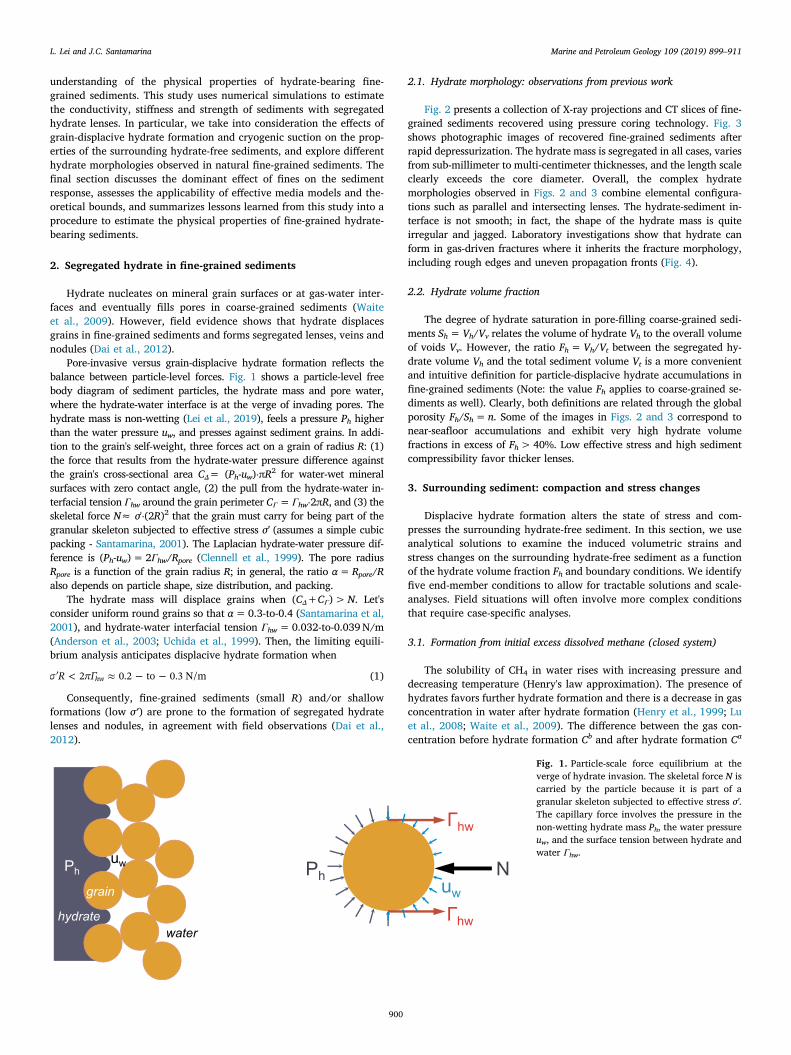
Pore-invasive versus grain-displacive hydrate formation reflects thebalance between particle-level forces. Fig. 1 shows a particle-level freebody diagram of sediment particles, the hydrate mass and pore water,where the hydrate-water interface is at the verge of invading pores. Thehydrate mass is non-wetting (Lei et al., 2019), feels a pressure Ph higherthan the water pressure uw, and presses against sediment grains. In addi-tion to the grain's self-weight, three forces act on a grain of radius R: (1)the force that results from the hydrate-water pressure difference againstthe grain's cross-sectional area CΔ= (Ph-uw)⋅πR2 for water-wet mineralsurfaces with zero contact angle, (2) the pull from the hydrate-water in-terfacial tension Γhw around the grain perimeter CΓ = Γhw⋅2πR, and (3) theskeletal force N≈ σ'⋅(2R)2 that the grain must carry for being part of thegranular skeleton subjected to effective stress σ' (assumes a simple cubicpacking - Santamarina, 2001). The Laplacian hydrate-water pressure dif-ference is (Ph-uw) = 2Γhw/Rpore (Clennell et al., 1999). The pore radiusRpore is a function of the grain radius R; in general, the ratio α=Rpore/Ralso depends on particle shape, size distribution, and packing.
The hydrate mass will displace grains when (CΔ+CΓ) >N. Let'sconsider uniform round grains so that α= 0.3-to-0.4 (Santamarina et al,2001), and hydrate-water interfacial tension Γhw = 0.032-to-0.039 N/m(Anderson et al., 2003; Uchida et al., 1999). Then, the limiting equili-brium analysis anticipates displacive hydrate formation when
<R 2 0.2 to 0.3 N/mhw (1)
Consequently, fine-grained sediments (small R) and/or shallowformations (low σ′) are prone to the formation of segregated hydratelenses and nodules, in agreement with field observations (Dai et al.,2012).
2.1. Hydrate morphology: observations from previous work
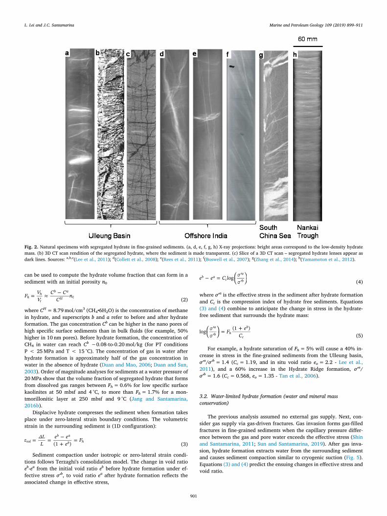
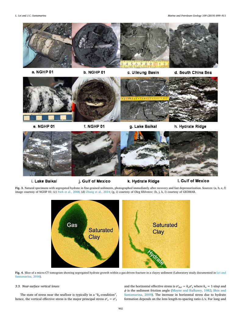
Fig. 2 presents a collection of X-ray projections and CT slices of fine-grained sediments recovered using pressure coring technology. Fig. 3shows photographic images of recovered fine-grained sediments afterrapid depressurization. The hydrate mass is segregated in all cases, variesfrom sub-millimeter to multi-centimeter thicknesses, and the length scaleclearly exceeds the core diameter. Overall, the complex hydratemorphologies observed in Figs. 2 and 3 combine elemental configura-tions such as parallel and intersecting lenses. The hydrate-sediment in-terface is not smooth; in fact, the shape of the hydrate mass is quiteirregular and jagged. Laboratory investigations show that hydrate canform in gas-driven fractures where it inherits the fracture morphology,including rough edges and uneven propagation fronts (Fig. 4).
2.2. Hydrate volume fraction
The degree of hydrate saturation in pore-filling coarse-grained sedi-ments Sh =Vh/Vv relates the volume of hydrate Vh to the overall volumeof voids Vv. However, the ratio Fh =Vh/Vt between the segregated hy-drate volume Vh and the total sediment volume Vt is a more convenientand intuitive definition for particle-displacive hydrate accumulations infine-grained sediments (Note: the value Fh applies to coarse-grained se-diments as well). Clearly, both definitions are related through the globalporosity Fh/Sh = n. Some of the images in Figs. 2 and 3 correspond tonear-seafloor accumulations and exhibit very high hydrate volumefractions in excess of Fh > 40%. Low effective stress and high sedimentcompressibility favor thicker lenses.
3. Surrounding sediment: compaction and stress changes
Displacive hydrate formation alters the state of stress and com-presses the surrounding hydrate-free sediment. In this section, we useanalytical solutions to examine the induced volumetric strains andstress changes on the surrounding hydrate-free sediment as a functionof the hydrate volume fraction Fh and boundary conditions. We identifyfive end-member conditions to allow for tractable solutions and scale-analyses. Field situations will often involve more complex conditionsthat require case-specific analyses.
3.1. Formation from initial excess dissolved methane (closed system)
The solubility of CH4 in water rises with increasing pressure anddecreasing temperature (Henry's law approximation). The presence ofhydrates favors further hydrate formation and there is a decrease in gasconcentration in water after hydrate formation (Henry et al., 1999; Luet al., 2008; Waite et al., 2009). The difference between the gas con-centration before hydrate formation Cb and after hydrate formation Ca
Fig. 1. Particle-scale force equilibrium at theverge of hydrate invasion. The skeletal force N iscarried by the particle because it is part of agranular skeleton subjected to effective stress σ'.The capillary force involves the pressure in thenon-wetting hydrate mass Ph, the water pressureuw, and the surface tension between hydrate andwater Γhw.
L. Lei and J.C. Santamarina Marine and Petroleum Geology 109 (2019) 899–911
900
can be used to compute the hydrate volume fraction that can form in asediment with an initial porosity n0
=F VV
C CC
nhh
t
b a
H 0 (2)
where CH = 8.79 mol/cm3 (CH4•6H2O) is the concentration of methanein hydrate, and superscripts b and a refer to before and after hydrateformation. The gas concentration Cb can be higher in the nano pores ofhigh specific surface sediments than in bulk fluids (for example, 50%higher in 10 nm pores). Before hydrate formation, the concentration ofCH4 in water can reach Cb ∼0.08-to-0.20 mol/kg (for PT conditionsP < 25 MPa and T < 15 °C). The concentration of gas in water afterhydrate formation is approximately half of the gas concentration inwater in the absence of hydrate (Duan and Mao, 2006; Duan and Sun,2003). Order of magnitude analyses for sediments at a water pressure of20 MPa show that the volume fraction of segregated hydrate that formsfrom dissolved gas ranges between Fh = 0.6% for low specific surfacekaolinites at 50 mbsf and 4 °C, to more than Fh = 1.7% for a mon-tmorillonitic layer at 250 mbsf and 9 °C (Jang and Santamarina,2016b).
Displacive hydrate compresses the sediment when formation takesplace under zero-lateral strain boundary conditions. The volumetricstrain in the surrounding sediment is (1D configuration):
= =+
=LL
e ee
F(1 )vol
b a
b h (3)
Sediment compaction under isotropic or zero-lateral strain condi-tions follows Terzaghi's consolidation model. The change in void ratioeb-ea from the initial void ratio eb before hydrate formation under ef-fective stress σ′b, to void ratio ea after hydrate formation reflects theassociated change in effective stress,
=e e C logb ac
a
b (4)
where σ′a is the effective stress in the sediment after hydrate formationand Cc is the compression index of hydrate free sediments. Equations(3) and (4) combine to anticipate the change in stress in the hydrate-free sediment that surrounds the hydrate mass:
= +F eC
log (1 )a
b hb
c (5)
For example, a hydrate saturation of Fh = 5% will cause a 40% in-crease in stress in the fine-grained sediments from the Ulleung basin,σ′a/σ′b= 1.4 (Cc = 1.19, and in situ void ratio eo = 2.2 - Lee et al.,2011), and a 60% increase in the Hydrate Ridge formation, σ′a/σ′b= 1.6 (Cc = 0.568, eo = 1.35 - Tan et al., 2006).
3.2. Water-limited hydrate formation (water and mineral massconservation)
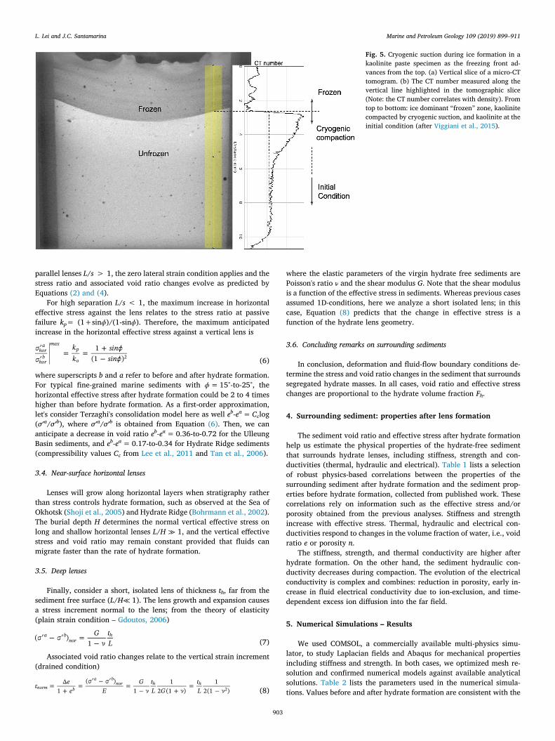
The previous analysis assumed no external gas supply. Next, con-sider gas supply via gas-driven fractures. Gas invasion forms gas-filledfractures in fine-grained sediments when the capillary pressure differ-ence between the gas and pore water exceeds the effective stress (Shinand Santamarina, 2011; Sun and Santamarina, 2019). After gas inva-sion, hydrate formation extracts water from the surrounding sedimentand causes sediment compaction similar to cryogenic suction (Fig. 5).Equations (3) and (4) predict the ensuing changes in effective stress andvoid ratio.
Fig. 2. Natural specimens with segregated hydrate in fine-grained sediments. (a, d, e, f, g, h) X-ray projections: bright areas correspond to the low-density hydratemass. (b) 3D CT scan rendition of the segregated hydrate, where the sediment is made transparent. (c) Slice of a 3D CT scan – segregated hydrate lenses appear asdark lines. Sources: a,b,c(Lee et al., 2011); d(Collett et al., 2008); e(Rees et al., 2011); f(Boswell et al., 2007); g(Zhang et al., 2014); h(Yamamoton et al., 2012).
L. Lei and J.C. Santamarina Marine and Petroleum Geology 109 (2019) 899–911
901
3.3. Near-surface vertical lenses
The state of stress near the seafloor is typically in a “ko-condition”,hence, the vertical effective stress is the major principal stress σ′z = σ′1
and the horizontal effective stress is σ′hor = koσ′z where ko ≈ 1-sinϕ andϕ is the sediment friction angle (Mayne and Kulhawy, 1982; Shin andSantamarina, 2009). The increase in horizontal stress due to hydrateformation depends on the lens length-to-spacing ratio L/s. For long and
Fig. 3. Natural specimens with segregated hydrate in fine-grained sediments, photographed immediately after recovery and fast depressurization. Sources: (a, b, e, f)image courtesy of NGHP 01; (c) Park et al., 2008; (d) Zhang et al., 2014; (g, i) courtesy of Oleg Khlvstov; (h, j, k, l) courtesy of GEOMAR.
Fig. 4. Slice of a micro-CT tomogram showing segregated hydrate growth within a gas-driven fracture in a clayey sediment (Laboratory study documented in Lei andSantamarina, 2018).
L. Lei and J.C. Santamarina Marine and Petroleum Geology 109 (2019) 899–911
902
parallel lenses L/s > 1, the zero lateral strain condition applies and thestress ratio and associated void ratio changes evolve as predicted byEquations (2) and (4).
For high separation L/s < 1, the maximum increase in horizontaleffective stress against the lens relates to the stress ratio at passivefailure kp= (1+sinϕ)/(1-sinϕ). Therefore, the maximum anticipatedincrease in the horizontal effective stress against a vertical lens is
= = +kk
sinsin
1(1 )
hora
horb
maxp
o2 (6)
where superscripts b and a refer to before and after hydrate formation.For typical fine-grained marine sediments with ϕ = 15°-to-25°, thehorizontal effective stress after hydrate formation could be 2 to 4 timeshigher than before hydrate formation. As a first-order approximation,let's consider Terzaghi's consolidation model here as well eb-ea=Cclog(σ′a/σ′b), where σ′a/σ′b is obtained from Equation (6). Then, we cananticipate a decrease in void ratio eb-ea = 0.36-to-0.72 for the UlleungBasin sediments, and eb-ea = 0.17-to-0.34 for Hydrate Ridge sediments(compressibility values Cc from Lee et al., 2011 and Tan et al., 2006).
3.4. Near-surface horizontal lenses
Lenses will grow along horizontal layers when stratigraphy ratherthan stress controls hydrate formation, such as observed at the Sea ofOkhotsk (Shoji et al., 2005) and Hydrate Ridge (Bohrmann et al., 2002).The burial depth H determines the normal vertical effective stress onlong and shallow horizontal lenses L/H ≫ 1, and the vertical effectivestress and void ratio may remain constant provided that fluids canmigrate faster than the rate of hydrate formation.
3.5. Deep lenses
Finally, consider a short, isolated lens of thickness th, far from thesediment free surface (L/H≪ 1). The lens growth and expansion causesa stress increment normal to the lens; from the theory of elasticity(plain strain condition – Gdoutos, 2006)
= G tL
( )1
a bnor
h(7)
Associated void ratio changes relate to the vertical strain increment(drained condition)
=+
= =+
=ee E
G tL G
tL1
( )1
12 (1 )
12(1 )norm b
a bnor h h
2 (8)
where the elastic parameters of the virgin hydrate free sediments arePoisson's ratio ν and the shear modulus G. Note that the shear modulusis a function of the effective stress in sediments. Whereas previous casesassumed 1D-conditions, here we analyze a short isolated lens; in thiscase, Equation (8) predicts that the change in effective stress is afunction of the hydrate lens geometry.
3.6. Concluding remarks on surrounding sediments
In conclusion, deformation and fluid-flow boundary conditions de-termine the stress and void ratio changes in the sediment that surroundssegregated hydrate masses. In all cases, void ratio and effective stresschanges are proportional to the hydrate volume fraction Fh.
4. Surrounding sediment: properties after lens formation
The sediment void ratio and effective stress after hydrate formationhelp us estimate the physical properties of the hydrate-free sedimentthat surrounds hydrate lenses, including stiffness, strength and con-ductivities (thermal, hydraulic and electrical). Table 1 lists a selectionof robust physics-based correlations between the properties of thesurrounding sediment after hydrate formation and the sediment prop-erties before hydrate formation, collected from published work. Thesecorrelations rely on information such as the effective stress and/orporosity obtained from the previous analyses. Stiffness and strengthincrease with effective stress. Thermal, hydraulic and electrical con-ductivities respond to changes in the volume fraction of water, i.e., voidratio e or porosity n.
The stiffness, strength, and thermal conductivity are higher afterhydrate formation. On the other hand, the sediment hydraulic con-ductivity decreases during compaction. The evolution of the electricalconductivity is complex and combines: reduction in porosity, early in-crease in fluid electrical conductivity due to ion-exclusion, and time-dependent excess ion diffusion into the far field.
5. Numerical Simulations – Results
We used COMSOL, a commercially available multi-physics simu-lator, to study Laplacian fields and Abaqus for mechanical propertiesincluding stiffness and strength. In both cases, we optimized mesh re-solution and confirmed numerical models against available analyticalsolutions. Table 2 lists the parameters used in the numerical simula-tions. Values before and after hydrate formation are consistent with the
Fig. 5. Cryogenic suction during ice formation in akaolinite paste specimen as the freezing front ad-vances from the top. (a) Vertical slice of a micro-CTtomogram. (b) The CT number measured along thevertical line highlighted in the tomographic slice(Note: the CT number correlates with density). Fromtop to bottom: ice dominant “frozen” zone, kaolinitecompacted by cryogenic suction, and kaolinite at theinitial condition (after Viggiani et al., 2015).
L. Lei and J.C. Santamarina Marine and Petroleum Geology 109 (2019) 899–911
903

sediment compaction process and the hydrate volume fraction, as dis-cussed above, and reflect physical correlations summarized in Table 1.
5.1. Conduction phenomena
Let's consider conduction phenomena so that flow q is a linearfunction of the gradient in the potential Ψ along the xi direction,
=q K x Ax
( )i ii (9)
where K is the conductivity and A is the cross sectional area (Note: thesame analysis applies to thermal, hydraulic and electrical conduction).
Heat transfer studies in COMSOL modelled the medium with∼60,000 triangular 2D-elements (mesh size varies with lens config-uration). The thermal conductivity is 2.6 Wm−1K−1 for the water-sa-turated hydrate-free sediment, and 0.57 Wm−1K−1 for the segregatedhydrate mass (Note: the hydrate thermal conductivity KT is similar tothat of water, and four times smaller than the thermal conductivity ofice (Rosenbaum et al., 2007; Warzinski et al., 2008)).
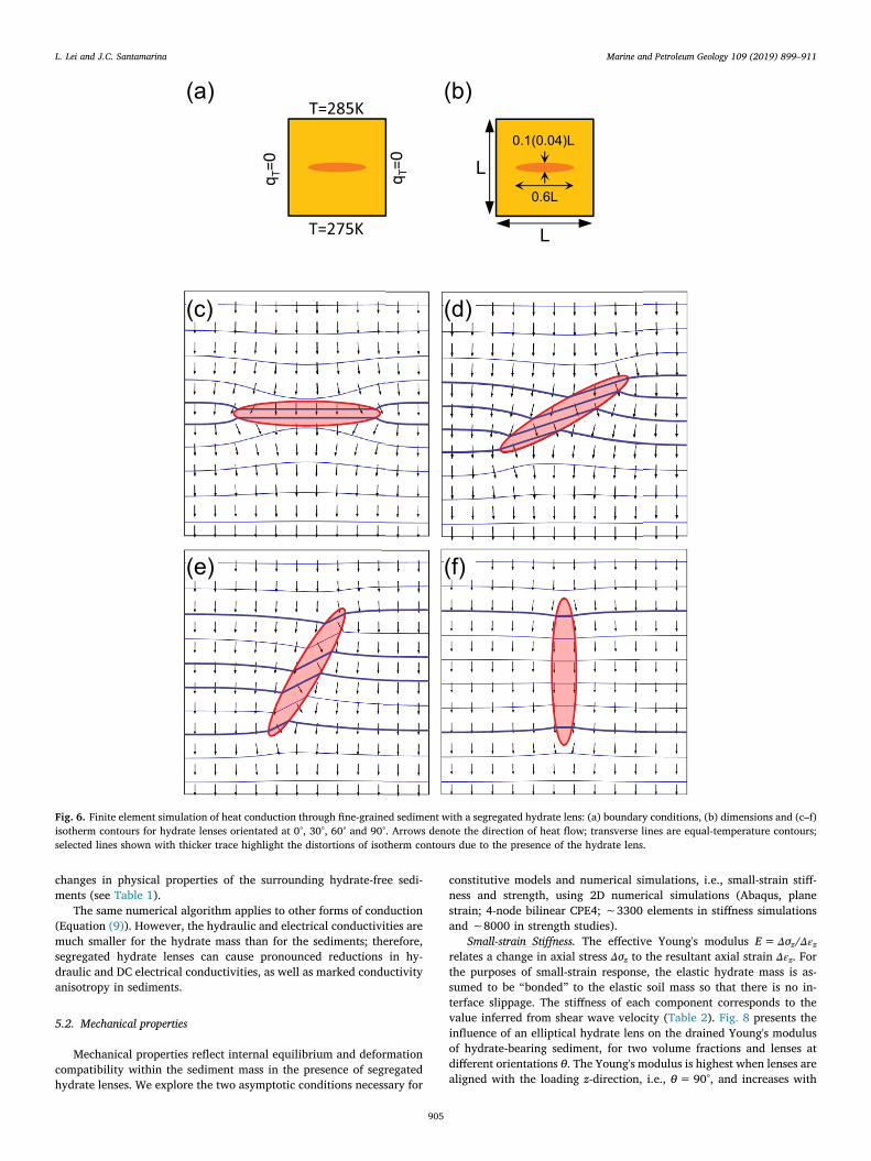
Fig. 6 demonstrates the influence of a segregated hydrate lens on thetemperature field: thermal conduction is significantly lower across thehydrate mass than in the surrounding sediment, therefore, temperaturecontour lines are closer to each other within the hydrate mass.
Fig. 7 compiles numerical simulation results for the effective thermal
conductivity KT as a function of lens orientation θ and hydrate volumefraction Fh. A single lens confers anisotropy to thermal conductivity, andthe effective thermal conductivity KT of the hydrate-bearing sedimenttracks the analytical solution for anisotropy in layered media,
= = +
= +
K KK K K
K K K
[cos sin ] 00
cossin cos sin
( ) sin
T0
900
290
2
0 90 02 (10)
where K0 and K90 are the effective thermal conductivities of hydrate-bearing sediments when the lens is perpendicular θ= 0° and parallelθ= 90° to the thermal gradient. We simulated other segregated hydratemorphologies, such as two intersecting lenses that form a cross-shapedhydrate mass (refer to Figs. 2 and 3); in this case, the effective thermalconductivity of the hydrate-bearing sediment was not sensitive to or-ientation. These results correspond to elemental configurations that canbe assembled to simulate hydrate morphologies in Figs. 2 and 3.
In general, the effect of sediment compaction around the hydratelens can be equally or more important to the effective thermal con-ductivity of the medium than the orientation of the lens (refer to KTb
and KTa in Fig. 7 and Table 2). The change in thermal conductivityΔKT =KTa–KTb is 0.2 Wm−1K−1, while the effect of lens orientation isΔKT =K90–K0 is 0.17 Wm−1K−1 (thick lens - Fig. 7). This result high-lights the effect of displacive hydrate formation and the ensuing
Table 1Change in the physical properties of hydrate-free sediments due to changes in effective stress and/or porosity after displacive hydrate formation - Physics-basedcorrelations extracted from previous studies.
Property Based on Property(after)/Property(before) Constitutive parameters (References)
Shear stiffness Hertz= ( )G kPa = ( )Ga
Gbab
β= 0.25–0.45 (Cha et al., 2014)
Shear strength Coulomb = tan• =ab
ab
Thermal conductivity Geometric mean =K K K•T mn
fn1
=KT
a
KTb
KmKf
nb na Km/Kf = 3–5 for clay (Horai and Simmons, 1969; Waite et al., 2009)
Hydraulic conductivity Kozeny-Carman = ( )K eHSs 2
= ( )KHa
KHb
ea
ebχ= 4–6 (Ren and Santamarina, 2018)
Electrical conductivity Archie =K n KE f = ( )KEa
KEb
na
nb= 1.36 3.5(Lovell, 1985)
Note.•Porosity n= Vv/Vt; void ratio e= Vv/Vs. Then: n= e/(1 + e).•Expressions assume that same constitutive parameters apply to the sediment before and after hydrate formation – Example: λ, β, tanϕ, χ, φ, ς, and specific surface Ss.•The pore fluid electrical conductivity Kf increases due to ion exclusion during hydrate formation. However, we assume that ionic diffusion brings the pore fluidconductivity back to its original values in the long term, and Kf cancels in the final expression for the electrical conductivity ratio.
Table 2Parameters used in analyses and numerical simulations. Values for sediments correspond to conditions after hydrate formation (Refer to Table 1).Sources: (1) Huang and Fan, 2005, (2) Cortes et al., 2009, (3) Waite et al., 2009, (4) Helgerud et al., 2009, (5) Durham et al., 2003.
Property Hydrate Water-saturated sediment before hydrate formation Water-saturated sediment after hydrate formation
Sediment Change (hydrate volume fraction Fh = 5% → σ′a/σ′b = 1.5)Void ratio n/a 0.76 0.67Stress [kPa] n/a 300 450ThermalConductivity KT [W m−1 K−1] 0.57 (1) 2.4 (2) 2.6 (2)
Heat Capacity Cp [J kg−1 K−1] 2031 (3) 1636c 1568c
Density ρ [kg m−3] 937 1937 1986MechanicalShear Modulus G [MPa] 3700 (4) 65 89Elastic Modulus E [MPa] 9600 (4) 157 (drained)a 214 (drained)a
Bulk Modulus B [MPa] 8400 (4) 87 (drained)a 119 (drained)a
Poisson's Ratio v [ ] 0.31 (4) 0.3 (large strain) 0.3 (large strain)Yield, failure criterion Elasto-plastic
σ′y = 25 MPa (5)Cam Clayb q= Μ p'
a From G assuming drained conditions and small-strain Poissons ratio of ν = 0.2.b Cam-clay parameters: compression index Cc = 0.5, void ratio at 1 kPa e1kPa = 2.0, swelling index Cs = 0.05; failure stress ratio Mf = 0.98.c Calculated by heat capacities of clay mineral Cpm = 894 J kg−1 K−1 and water Cpw = 4218 J kg−1 K−1 and their weight fractions Cp = Cpm(1/(1 + w)) + Cpw(w/
(1 + w)), where w is the water content.
L. Lei and J.C. Santamarina Marine and Petroleum Geology 109 (2019) 899–911
904
changes in physical properties of the surrounding hydrate-free sedi-ments (see Table 1).
The same numerical algorithm applies to other forms of conduction(Equation (9)). However, the hydraulic and electrical conductivities aremuch smaller for the hydrate mass than for the sediments; therefore,segregated hydrate lenses can cause pronounced reductions in hy-draulic and DC electrical conductivities, as well as marked conductivityanisotropy in sediments.
5.2. Mechanical properties
Mechanical properties reflect internal equilibrium and deformationcompatibility within the sediment mass in the presence of segregatedhydrate lenses. We explore the two asymptotic conditions necessary for
constitutive models and numerical simulations, i.e., small-strain stiff-ness and strength, using 2D numerical simulations (Abaqus, planestrain; 4-node bilinear CPE4; ∼3300 elements in stiffness simulationsand ∼8000 in strength studies).
Small-strain Stiffness. The effective Young's modulus E= Δσz/Δεzrelates a change in axial stress Δσz to the resultant axial strain Δεz. Forthe purposes of small-strain response, the elastic hydrate mass is as-sumed to be “bonded” to the elastic soil mass so that there is no in-terface slippage. The stiffness of each component corresponds to thevalue inferred from shear wave velocity (Table 2). Fig. 8 presents theinfluence of an elliptical hydrate lens on the drained Young's modulusof hydrate-bearing sediment, for two volume fractions and lenses atdifferent orientations θ. The Young's modulus is highest when lenses arealigned with the loading z-direction, i.e., θ= 90°, and increases with
Fig. 6. Finite element simulation of heat conduction through fine-grained sediment with a segregated hydrate lens: (a) boundary conditions, (b) dimensions and (c–f)isotherm contours for hydrate lenses orientated at 0°, 30°, 60° and 90°. Arrows denote the direction of heat flow; transverse lines are equal-temperature contours;selected lines shown with thicker trace highlight the distortions of isotherm contours due to the presence of the hydrate lens.
L. Lei and J.C. Santamarina Marine and Petroleum Geology 109 (2019) 899–911
905
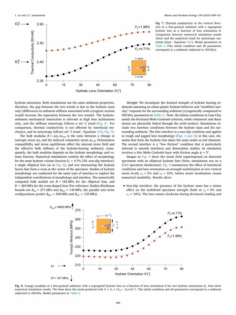
hydrate saturation. Both simulations use the same sediment properties,therefore, the gap between the two trends is due to the hydrate massonly (differences in sediment stiffness associated with cryogenic suctionwould increase the separation between the two trends). The hydrate-sediment mechanical interaction is relevant at high lens inclinationsonly, and the stiffness anisotropy follows a sin2 trend (Fig. 8 - Forcomparison, thermal conductivity is not affected by interfacial me-chanics, and its anisotropy follows sin6 trend - Equation (10), Fig. 7).
The bulk modulus B= Δσo/Δεvol is the ratio between a change inisotropic stress Δσo and the induced volumetric strain Δεvol. Deformationcompatibility and stress equilibrium affect the internal stress field andthe effective bulk stiffness of the hydrate-bearing sediment; conse-quently, the bulk modulus depends on the hydrate morphology and vo-lume fraction. Numerical simulations confirm the effect of morphologyfor the same hydrate volume fraction Fh = 4.7% (3D, non-slip interface):a single elliptical lens (as in Fig. 6), and two intersecting flat hydratelayers that form a cross at the center of the specimen. Studies of hydratemorphology are conducted for the same type of interface to explore theindependent contributions of morphology and interface. The numericallycomputed bulk moduli are B= 182 MPa for the elliptical lens, andB= 269 MPa for the cross-shaped lens (For reference: Hashin-Shtrikmanbounds are Bup = 271 MPa and Blow = 130 MPa; the parallel and seriesconfigurations predict Bpar = 509 MPa and Bser = 125 MPa).
Strength. We investigate the drained strength of hydrate bearing se-diments assuming an elasto-plastic hydrate behavior and “modified cam-clay” response for the surrounding sediment (cryogenically compacted to450 kPa; parameters in Table 2 – Note: the failure conditions in Cam-Claysatisfy the frictional Mohr-Coulomb criterion, while volumetric and shearstrains are physically linked through the yield surface). Simulations in-clude two interface conditions between the hydrate mass and the sur-rounding sediment. The first interface is a non-slip condition and appliesto rough and jagged lens morphology (Figs. 2 and 3); in this case, ele-ments that form the hydrate lens share the same nodes as soil elements.The second interface is a “low friction” condition that is particularlyrelevant to smooth interfaces and dissociation studies; its simulationinvolves a thin Mohr-Coulomb layer with friction angle ϕ = 5°.
Images in Fig. 9 show the strain field superimposed on distortedspecimens with an elliptical hydrate lens (Note: simulations run on a2.5:1 specimen slenderness). Fig. 9 summarizes the effect of interfacialconditions and lens orientation on strength mobilization at two verticalstrain levels εz = 5% and εz = 10%, before strain localization causesnumerical instability. Results show:
• Non-slip interface: the presence of the hydrate mass has a minoreffect on the mobilized specimen strength (both at εz = 5% andεz = 10%). The lens rotates clockwise during deviatoric loading and
Fig. 7. Thermal conductivity in the vertical direc-tion in a fine-grained sediment with a segregatedhydrate lens as a function of lens orientation θ.Comparison between numerical simulation results(dots) and the analytical trend for anisotropic ma-terials (lines - Equation (10)). Model parameters inTable 2 (The initial condition and all parameterscorrespond to a sediment subjected to 450 kPa).
Fig. 8. Young's modulus of a fine-grained sediment with a segregated hydrate lens as a function of lens orientation θ for two hydrate saturations Fh. Dots shownumerical simulation results. The lines show the trend predicted with = +E E E E( ) sin0 90 0
6 . The initial condition and all parameters correspond to a sedimentsubjected to 450 kPa. Model parameters in Table 2.
L. Lei and J.C. Santamarina Marine and Petroleum Geology 109 (2019) 899–911
906
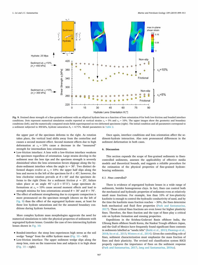
the upper part of the specimen deforms to the right. As rotationtakes place, the vertical load shifts away from the centerline andcauses a second moment effect. Second moment effects due to highdeformation at εz = 10% cause a decrease in the “measured”strength for intermediate lens orientations.
• Low-friction interface: A lens with a low-friction interface weakensthe specimen regardless of orientation. Large strains develop in thesediment near the lens tips and the specimen strength is severelydiminished when the lens orientation favors slippage along the hy-drate-sediment interface when the angle is ≈ 30°. Two distinct de-formed shapes evolve at εz = 10%: the upper half slips along thelens and moves to the left of the specimen for θ≤ 45°; however, thelens clockwise rotation prevails at θ≥ 60° and the specimen de-forms to the right (Note: for a sediment friction ϕ = 25°, failuretakes place at an angle 45°+ϕ/2 = 57.5°). Large specimen de-formations at εz = 10% cause second moment effects and lead tostrength minima for lens orientations around θ≈ 30° and θ≈ 70°.
• The effect of sediment strengthening due to cryogenic compaction ismore pronounced on the specimen strength (shown on the left ofFig. 9) than the effect of the segregated hydrate mass, at least forthese low hydrate saturations and for the assumed boundary con-ditions during hydrate formation.
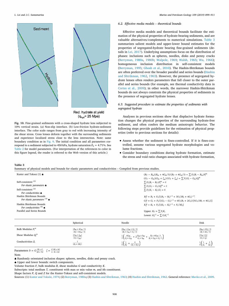
More complex hydrate mass morphologies aggravate the need fornumerical simulations to infer the physical properties of sediments withsegregated hydrate lenses. Consider the case of two-intersecting hydratelenses shown in Fig. 10:
• Bonded-interface: the steep lens experiences high stress as the soilwedge “hangs” from the stiffer hydrate mass (Fig. 10 – left).
• Low-friction interface: The upper sediment wedge slips along thesteep lens, rests on the transverse lens and subjects it to high shear(Fig. 10 – right).
Once again, interface conditions and lens orientation affect the se-diment-hydrate interaction. Also note pronounced differences in thesediment deformation in both cases.
6. Discussion
This section expands the scope of fine-grained sediments to fines-controlled sediments, assesses the applicability of effective mediamodels and theoretical bounds, and suggests a reliable procedure forthe estimation of the physical properties of fine-grained hydrate-bearing sediments.
6.1. Fines controlled?
There is evidence of segregated hydrate lenses in a wide range ofsediments, besides homogeneous clays. In fact, fines can control boththe mechanical and hydraulic properties of sediments even at relativelysmall mass fractions. For example, less than 10% of low-plasticitykaolinite is enough to control the hydraulic conductivity of sand, and bythe time the kaolinite mass fraction reaches ∼30%, the fines determineboth mechanical and fluid flow properties (Park and Santamarina,2017). These critical fines fractions are even lower for higher plasticityfines. Therefore, the fines fraction and the type of fines play a criticalrole on hydrate formation and ensuing properties.
Expeditions in the Krishna-Godavari Basin offshore India, theUlleung Basin offshore South Korea, the Nankai Trough offshore Japan,and the Gulf of Mexico have frequently found significant fines contentsin sediments labelled as “sands/silts” (Bahk et al., 2013; Flemings et al.,2018; Ito et al., 2015; Winters et al., 2014). Given the controlling role offines, sediment characterization must emphasize the mass fraction offines and their plasticity. The revised soil classification system RSCSproperly captures the importance of fines on the sediment response(Park and Santamarina, 2017; Jang and Santamarina, 2016a).
Fig. 9. Drained shear strength of a fine-grained sediment with an elliptical hydrate lens as a function of lens orientation θ for both low-friction and bonded interfaceconditions. Dots represent numerical simulation results reported at vertical strains εz = 5% and εz = 10%. The upper images show the geometry and boundaryconditions (left), and the numerically computed strain fields superimposed on two deformed specimens (right). The initial condition and all parameters correspond toa sediment subjected to 450 kPa, hydrate saturation Fh = 4.71%. Model parameters in Table 2.
L. Lei and J.C. Santamarina Marine and Petroleum Geology 109 (2019) 899–911
907
6.2. Effective media models – theoretical bounds
Effective media models and theoretical bounds facilitate the esti-mation of the physical properties of hydrate-bearing sediments, and arevaluable alternatives/complements to numerical simulations. Table 3summarizes salient models and upper-lower bound estimates for theproperties of segregated-hydrate bearing fine-grained sediments (de-tails in Lei, 2017). Underlying assumptions focus on the distribution ofphases: inclusions such as spheres, needles, disks and penny cracks(Berryman, 1980a, 1980b; Walpole, 1969; Walsh, 1965; Wu, 1966);homogeneous inclusion distribution in self-consistent models(Berryman, 1995; Ghosh et al., 2010). The Hashin-Shtrikman boundsare often preferred over the broader parallel and series bounds (Hashinand Shtrikman, 1962, 1963). However, the presence of segregated hy-drate lenses often renders parameters that fall closer to the outer par-allel and series bounds (for example, see thermal conductivity data inCortes et al., 2009); in other words, the narrower Hashin-Shtrikmanbounds do not always constrain the physical properties of sediments inthe presence of segregated hydrate lenses.
6.3. Suggested procedure to estimate the properties of sediments withsegregated hydrate
Analyses in previous sections show that displacive hydrate forma-tion changes the physical properties of the surrounding hydrate-freesediment, and often confers the medium anisotropic behavior. Thefollowing steps provide guidelines for the estimation of physical prop-erties (refer to previous sections for details):
• Assess whether the sediment is fines-controlled. If it is fines-con-trolled, assume various segregated hydrate morphologies and vo-lume fractions.
• Consider boundary conditions during hydrate formation, estimatethe stress and void ratio changes associated with hydrate formation,
Fig. 10. Fine-grained sediments with a cross-shaped hydrate lens subjected to10% vertical strain. (a) Non-slip interface. (b) Low-friction hydrate-sedimentinterface. The color scale ranges from gray to red with increasing intensity ofthe shear stress. Cross lenses deform together with the surrounding sedimentsand experience localized stress close to the lens intersection. Note: sameboundary condition as in Fig. 9. The initial condition and all parameters cor-respond to a sediment subjected to 450 kPa, hydrate saturation Fh = 4.71%. SeeTable 2 for model parameters. (For interpretation of the references to color inthis figure legend, the reader is referred to the Web version of this article.)
Table 3Summary of physical models and bounds for elastic parameters and conductivities – Compiled from previous studies.
Kuster and Toksoz (1) ♣ + + =B B B G B G F B B P( )( 4 /3)/( 4 /3) ( )T m m m T m i i m im
+ + =G G G G F G G Q( )( )/( ) ( )T m m m T m i i m im
Self-consistent (2)
For elastic parameters ♣=F B B P( ) 0i i T i
m
=F G G Q( ) 0i i T im
Self-consistent (2)
For conductivities ♣=F K K Z( ) 0i i T i
Hashin Shtrikman BoundsFor elastic parameters (3) ♠
= + + +±B B F B B F B G/[( ) 3 (3 4 ) ]T 1 2 2 1 1 1 1 1 1
= + + + +±G G F G G F B G G B G/[( ) 6 ( 2 )/[5 (3 4 )]]T 1 2 2 1 1 1 1 2 1 1 1Hashin Shtrikman Bounds
For conductivities (4) ♠= + +±K K F K K F K/[( ) /3 ]T 1 2 2 1 1 1 2
Parallel and Series Bounds Upper: =K F KT i i
Lower: =K F KT i i1 1
Spherical Needle Disk
Bulk Modulus Pim ++
Bm GmBi Gm
( 4 / 3)( 4 / 3)
+ ++ +
Bm Gm GiBi Gm Gi
( / 3)( / 3)
++
Bm GiBi Gi
( 4 / 3)( 4 / 3)
Shear Modulus Qim +
+Gm mGi m
( )( ) + ++
++
++ +( )2Gm
Gi GmGm mGi m
Bi GmBi Gm Gi
15
4 4 / 3/ 3
++
Gm iGi i
( )( )
Conductivities Zi+Ki KT
1( 2 ) + +( )KT Ki KT
19
1 4( ) +( )Ki KT
19
1 2
Parameters = =++
++G B G
B GG B G
B G3
3 7 69 8
2Note.♣ Randomly orientated inclusion shapes: spheres, needles, disks and penny crack.♠ Upper and lower bounds: switch components.Volume fraction F, bulk modulus B, shear modulus G and conductivity K.Subscripts: total medium T, constituent with max or min value m, and ith constituent.Shape factors P, Q and Z for the Kuster-Toksoz and self-consistent models.Sources: (1) Kuster and Toksöz, 1974; (2) Berryman, 1980a; (3) Hashin and Shtrikman, 1963; (4) Hashin and Shtrikman, 1962. General reference: Mavko et al., 2009.
L. Lei and J.C. Santamarina Marine and Petroleum Geology 109 (2019) 899–911
908
and compute the modified properties for the hydrate-free sedimentthat surrounds the hydrate mass.
• Use numerical simulations or analytical models to compute theproperties of the hydrate-bearing sediment. Consider hydrate con-figurations that are both parallel and normal to the imposed gradientsor stresses. Vary hydrate-sediment interfacial conditions to representfield conditions of interest (e.g., rough and weak-frictional).
• Adopt an anisotropic variation with lens orientation θ that reflectsthe morphology of the hydrate mass.
7. Conclusions
The physical properties of hydrate-bearing sediments are critical forthe analysis of mechanical stability and settlement, heat and fluid flowevaluations, and the design of gas production strategies. However, theassessment of physical properties is particularly challenging in fine-grained sediments due to (1) inherent difficulties in hydrate formationin the laboratory, and (2) specimen size requirements for a re-presentative volume in fine-grained sediments with segregated gashydrate. This study has circumvented these limitations by combiningconceptual models and numerical simulations, leading to the conclu-sions below:
• Hydrate formation is grain-displacive when σ′R < 2πΓhw≈ 0.2-to-0.3 N/m. Therefore, segregated hydrate is to be expected in fine-grained sediments (small R) and/or shallow formations (low σ′).Field evidence confirms this observation.
• Fines control the sediment mechanical and transport responses evenat a relatively small fines fraction. Fines-controlled sediments areprone to segregated hydrate formation. In fact, sediments may ex-hibit hydrate lenses even when 80–90% of their mass is sand.
• Grain-displacive hydrate growth and cryogenic suction alter thephysical properties of the “hydrate-free” sediment that surroundsthe segregated hydrate mass. Stress and fluid flow boundary con-ditions determine the changes in effective stress and void ratio for agiven hydrate volume fraction.
• The physical changes in the surrounding hydrate-free sediment canbe more important on overall sediment properties than the presenceof hydrate itself, as shown for the cases of strength and thermalconductivity. Thus, numerical simulations and effective mediamodels need to consider both the hydrate morphology and the up-dated properties of the sediments around segregated hydrates.
• The effect of segregated hydrate on effective media properties re-flects the hydrate morphology (shape, persistence, thickness, or-ientation), the physical properties of both the hydrate and sediment,and the interaction between the hydrate mass with the sediment. Inthe case of mechanical properties, this interaction implies compat-ibility of deformations and equilibrium (as highlighted by bulkmodulus estimations); in the case of transport properties it impliescontinuity and conservation (heat, mass, and charge).
• Sediments with parallel hydrate lenses exhibit anisotropic conduc-tion and mechanical properties, however anisotropy is less pro-nounced when lenses form intersecting cross-configurations.
• Laboratory formation and recovered cores show that the interfacebetween the segregated hydrate and the surrounding sediment isrough and jagged. Yet, hydrate-sediment interaction evolves duringdissociation and very low frictional resistance is anticipated at thehydrate-sediment interface.
Acknowledgements
Support for this research was provided by the U.S. Department ofEnergy, the Goizueta Foundation, and the KAUST endowment. LingliPan tested numerical simulations. Gabrielle E. Abelskamp edited themanuscript. All the data used in this article are included in the tablesand figures.
Notation
A Cross sectional areaB Bulk modulus (Subscripts: low & up: Hashin-Shtrikman
bounds; par & ser: parallel and series)CΔ Hydrate-water pressure difference against the grain's cross-
sectional areaCΓ Pull due to hydrate-water interfacial tension Γhw around the
grain perimeterC Gas concentration (Superscripts: b= before and a= after
hydrate formation)Cc Compression index of hydrate free sedimentsCH Concentration of methane in hydratee Void ratio (Superscripts b&a= before and after hydrate for-
mation. Subscript: 0 = in situ)E Young's modulusFh Hydrate volume fractionG Shear modulus of virgin sedimentsH Burial depthko Lateral earth pressure coefficient (Subscripts: o= at rest,
p= at passive failure)K ConductivityKT Thermal conductivity (Subscripts: hyd= hydrate, ice= ice,
w= water. Superscripts: b= before and a= after hydrateformation)
K0 Effective thermal conductivity of hydrate-bearing sediment(Subscript: 0 = when the lens is perpendicular and90=when the lens is parallel to the thermal gradient)
L Hydrate lens lengthn Global porosity (Subscript 0 = initial)N Skeletal forcePh Pressure in the hydrate massq Flow rateR Grain radiusRpore Pore throat radiuss Spacing between adjacent lensesSh Hydrate saturationth Lens thicknessuw Pressure in waterV Volume (Subscripts: h= hydrate, t= total sediment volume,
v= voids)xi ith direction in the coordinationα Ratio between pore radius and grain radiusε Strain (Subscript: z= axial in z direction, vol= volumetric)ϕ Sediment friction angleΓhw Hydrate-water interfacial tensionν Poisson's ratio of virgin sedimentsθ Lens orientationσ′ Effective stress (Superscripts: b= before and a= after hy-
drate formation. Subscripts: 0 = isotropic, z= vertical,hor= horizontal, nor= normal to lens, 1 = major principal)
Ψ Potential
References
Anderson, R., Llamedo, M., Tohidi, B., Burgass, R.W., 2003. Experimental measurementof methane and carbon dioxide clathrate hydrate equilibria in mesoporous silica. J.Phys. Chem. B 107 (15), 3507–3514. https://doi.org/10.1021/jp0263370.
Archer, D., 2007. Methane hydrate stability and anthropogenic climate change.Biogeosciences 4 (4), 521–544. https://doi.org/10.5194/bg-4-521-2007.
Bahk, J.J., Kim, D.H., Chun, J.H., Son, B.K., Kim, J.H., Ryu, B.J., et al., 2013. Gas hydrateoccurrences and their relation to host sediment properties: results from secondUlleung basin gas hydrate drilling expedition, East Sea. Mar. Pet. Geol. 47, 21–29.https://doi.org/10.1016/j.marpetgeo.2013.05.006.
Berryman, J.G., 1980a. Long-wavelength propagation in composite elastic media I.Spherical inclusions. J. Acoust. Soc. Am. 68 (6), 1809–1819. https://doi.org/10.1121/1.385171.
Berryman, J.G., 1980b. Long-wavelength propagation in composite elastic media II.Ellipsoidal inclusions. J. Acoust. Soc. Am. 68 (6), 1820–1831. https://doi.org/10.
L. Lei and J.C. Santamarina Marine and Petroleum Geology 109 (2019) 899–911
909
1121/1.385172.Berryman, J.G., 1995. Mixture theories for rock properties. In: Ahrens, T.J. (Ed.), Rock
Physics & Phase Relations: A Handbook of Physical Constants. American GeophysicalUnion, Washington, DC, pp. 205–228. https://doi.org/10.1029/RF003p0205.
Bohrmann, G., Suess, E., Greinert, J., Teichert, B., Naehr, T., 2002. Gas hydrate carbo-nates from Hydrate Ridge, cascadia convergent margin: indicators of near-seafloorclathrate deposits. In: Proceedings of the 4th International Conference on GasHydrates (ICGH 2002), Yokohama, Japan.
Boswell, R., 2009. Is gas hydrate energy within reach? Science 325 (5943), 957–958.https://doi.org/10.1126/science.1175074.
Boswell, R., Collett, T.S., 2011. Current perspectives on gas hydrate resources. EnergyEnviron. Sci. 4 (4), 1206–1215. https://doi.org/10.1039/C0EE00203H.
Boswell, R., Kleinberg, R., Collett, T., Frye, M., 2007. Exploration priorities for marine gashydrate resources. Fire in the Ice 7 (2), 11–13. https://www.netl.doe.gov/sites/default/files/publication/HMNewsSpringSummer07.pdf.
Cha, M., Santamarina, J.C., Kim, H.-S., Cho, G.-C., 2014. Small-strain stiffness, shear-wave velocity, and soil compressibility. J. Geotech. Geoenviron. Eng. 140 (10),06014011. https://doi.org/10.1061/(ASCE)GT.1943-5606.0001157.
Clennell, M.B., Hovland, M., Booth, J.S., Henry, P., Winters, W.J., 1999. Formation ofnatural gas hydrates in marine sediments: 1. Conceptual model of gas hydrate growthconditioned by host sediment properties. J. Geophys. Res.: Solid Earth 104 (B10),22985–23003. https://doi.org/10.1029/1999JB900175.
Collett, T.S., 2002. Energy resource potential of natural gas hydrates. AAPG (Am. Assoc.Pet. Geol.) Bull. 86 (11), 1971–1992. https://doi.org/10.1306/61EEDDD2-173E-11D7-8645000102C1865D.
Collett, T.S., Riedel, M., Cochran, J.R., Boswell, R., Kumar, P., Sathe, A.V., 2008. Indiancontinental margin gas hydrate prospects: results of the Indian national gas hydrateprogram (NGHP) expedition 01. In: Proceedings of the 6th International Conferenceon Gas Hydrates (ICGH 2008), Vancouver, British Columbia, Canada.
Cook, A.E., Goldberg, D., Kleinberg, R.L., 2008. Fracture-controlled gas hydrate systemsin the northern Gulf of Mexico. Mar. Pet. Geol. 25 (9), 932–941. https://doi.org/10.1016/j.marpetgeo.2008.01.013.
Cortes, D.D., Martin, A.I., Yun, T.S., Francisca, F.M., Santamarina, J.C., Ruppel, C., 2009.Thermal conductivity of hydrate-bearing sediments. J. Geophys. Res.: Solid Earth 114(B11), B11103. https://doi.org/10.1029/2008JB006235.
Dai, S., Santamarina, J.C., 2014. Sampling disturbance in hydrate-bearing sedimentpressure cores: NGHP-01 expedition, Krishna–Godavari Basin example. Mar. Pet.Geol. 58, 178–186. https://doi.org/10.1016/j.marpetgeo.2014.07.013.
Dai, S., Santamarina, J.C., Waite, W.F., Kneafsey, T.J., 2012. Hydrate morphology: phy-sical properties of sands with patchy hydrate saturation. J. Geophys. Res.: Solid Earth117 (B11), B11205. https://doi.org/10.1029/2012JB009667.
Duan, Z., Mao, S., 2006. A thermodynamic model for calculating methane solubility,density and gas phase composition of methane-bearing aqueous fluids from 273 to523K and from 1 to 2000bar. Geochem. Cosmochim. Acta 70 (13), 3369–3386.https://doi.org/10.1016/j.gca.2006.03.018.
Duan, Z., Sun, R., 2003. An improved model calculating CO2 solubility in pure water andaqueous NaCl solutions from 273 to 533 K and from 0 to 2000 bar. Chem. Geol. 193(3), 257–271. https://doi.org/10.1016/S0009-2541(02)00263-2.
Durham, W.B., Kirby, S.H., Stern, L.A., Zhang, W., 2003. The strength and rheology ofmethane clathrate hydrate. J. Geophys. Res.: Solid Earth 108 (B4), 2182. https://doi.org/10.1029/2002JB001872.
Flemings, P.B., Phillips, S.C., Collett, T., Cook, A., Boswell, R., the UT-GOM2-1 ExpeditionScientists, 2018. UT-GOM2-1 hydrate pressure coring expedition hole GC 955 H002.In: Flemings, P.B. (Ed.), UT-GOM2-1 Hydrate Pressure Coring Expedition Report(Chap. 3). University of Texas Institute for Geophysics, Austin, TX. http://www-udc.ig.utexas.edu/gom2/Chapter%203%20-%20H002.pdf.
Gdoutos, E.E., 2006. Fracture Mechanics: an Introduction, second ed. Springer,Dordrecht, The Netherlands. https://doi.org/10.1007/1-4020-3153-X.
Ghosh, R., Sain, K., Ojha, M., 2010. Effective medium modeling of gas hydrate-filledfractures using the sonic log in the Krishna-Godavari basin, offshore eastern India. J.Geophys. Res.: Solid Earth 115 (B6), B06101. https://doi.org/10.1029/2009JB006711.
Grozic, J.L.H., 2010. Interplay between gas hydrates and submarine slope failure. In:Mosher, D.C. (Ed.), Submarine Mass Movements and Their Consequences (Chap. 2).Springer Science & Business Media, Dordrecht, The Netherlands, pp. 11–30. https://doi.org/10.1007/978-90-481-3071-9_2.
Hashin, Z., Shtrikman, S., 1962. A variational approach to the theory of the effectivemagnetic permeability of multiphase materials. J. Appl. Phys. 33 (10), 3125–3131.https://doi.org/10.1063/1.1728579.
Hashin, Z., Shtrikman, S., 1963. A variational approach to the theory of the elastic be-haviour of multiphase materials. J. Mech. Phys. Solids 11 (2), 127–140. https://doi.org/10.1016/0022-5096(63)90060-7.
Helgerud, M.B., Waite, W.F., Kirby, S.H., Nur, A., 2009. Elastic wave speeds and moduli inpolycrystalline ice Ih, sI methane hydrate, and sII methane-ethane hydrate. J.Geophys. Res.: Solid Earth 114 (B2), B02212. https://doi.org/10.1029/2008JB006132.
Henry, P., Thomas, M., Clennell, M.B., 1999. Formation of natural gas hydrates in marinesediments: 2. Thermodynamic calculations of stability conditions in porous sedi-ments. J. Geophys. Res.: Solid Earth 104 (B10), 23005–23022. https://doi.org/10.1029/1999JB900167.
Horai, K.-i., Simmons, G., 1969. Thermal conductivity of rock-forming minerals. EarthPlanet. Sci. Lett. 6 (5), 359–368. https://doi.org/10.1016/0012-821X(69)90186-1.
Hornbach, M.J., Lavier, L.L., Ruppel, C.D., 2007. Triggering mechanism and tsunamo-genic potential of the Cape Fear Slide complex, U.S. Atlantic margin. Geochem.Geophys. Geosyst. 8 (12), Q12008. https://doi.org/10.1029/2007GC001722.
Huang, D., Fan, S., 2005. Measuring and modeling thermal conductivity of gas hydrate-
bearing sand. J. Geophys. Res.: Solid Earth 110 (B1), B01311. https://doi.org/10.1029/2004JB003314.
Hvorslev, M.J., 1949. Subsurface Exploration and Sampling of Soils for Civil EngineeringPurposes. Soil Mechanics and Foundations Division, American Society of CivilEngineers, Vicksburg, Mississippi.
Ito, T., Komatsu, Y., Fujii, T., Suzuki, K., Egawa, K., Nakatsuka, Y., et al., 2015.Lithological features of hydrate-bearing sediments and their relationship with gashydrate saturation in the eastern Nankai Trough, Japan. Mar. Pet. Geol. 66, 368–378.https://doi.org/10.1016/j.marpetgeo.2015.02.022.
Jang, J., Santamarina, J.C., 2016a. Fines classification based on sensitivity to pore-fluidchemistry. J. Geotech. Geoenviron. Eng. 142 (4), 06015018. https://doi.org/10.1061/(ASCE)GT.1943-5606.0001420.
Jang, J., Santamarina, J.C., 2016b. Hydrate bearing clayey sediments: formation and gasproduction concepts. Mar. Pet. Geol. 77, 235–246. https://doi.org/10.1016/j.marpetgeo.2016.06.013.
Kuster, G.T., Toksöz, M.N., 1974. Velocity and attenuation of seismic waves in two-phasemedia: Part I. Theoretical formulations. Geophysics 39 (5), 587–606. https://doi.org/10.1190/1.1440450.
Kvalstad, T.J., Andresen, L., Forsberg, C.F., Berg, K., Bryn, P., Wangen, M., 2005. TheStoregga slide: evaluation of triggering sources and slide mechanics. Mar. Pet. Geol.22 (1), 245–256. https://doi.org/10.1016/j.marpetgeo.2004.10.019.
Kwon, T.-H., Cho, G.-C., Santamarina, J.C., 2008. Gas hydrate dissociation in sediments:pressure-temperature evolution. Geochem. Geophys. Geosyst. 9 (3), Q03019. https://doi.org/10.1029/2007GC001920.
Lee, C., Yun, T.S., Lee, J.-S., Bahk, J.J., Santamarina, J.C., 2011. Geotechnical char-acterization of marine sediments in the Ulleung basin, East Sea. Eng. Geol. 117 (1),151–158. https://doi.org/10.1016/j.enggeo.2010.10.014.
Lee, J.Y., Jung, J.W., Lee, M.H., Bahk, J.J., Choi, J., Ryu, B.J., Schultheiss, P., 2013.Pressure core based study of gas hydrates in the Ulleung Basin and implication forgeomechanical controls on gas hydrate occurrence. Mar. Pet. Geol. 47, 85–98.https://doi.org/10.1016/j.marpetgeo.2013.05.021.
Lei, L., 2017. Gas Hydrate in Fine-Grained Sediments—Laboratory Studies and CoupledProcesses Analyses. (PhD). Georgia Institute of Technology, Atlanta Retrieved from.http://hdl.handle.net/1853/58215.
Lei, L., Santamarina, J.C., 2018. Laboratory strategies for hydrate formation in fine-grained sediments. J. Geophys. Res.: Solid Earth 123 (4), 2583–2596. https://doi.org/10.1002/2017JB014624.
Lei, L., Seol, Y., Choi, J.-H., Kneafsey, T.J., 2019. Pore habit of methane hydrate and itsevolution in sediment matrix – laboratory visualization with phase-contrast micro-CT. Mar. Pet. Geol. 104, 451–467. https://doi.org/10.1016/j.marpetgeo.2019.04.004.
Lovell, M.A., 1985. Thermal conductivity and permeability assessment by electrical re-sistivity measurements in marine sediments. Mar. Geotechnol. 6 (2), 205–240.https://doi.org/10.1080/10641198509388187.
Lu, W., Chou, I.M., Burruss, R.C., 2008. Determination of methane concentrations inwater in equilibrium with sI methane hydrate in the absence of a vapor phase by insitu Raman spectroscopy. Geochem. Cosmochim. Acta 72 (2), 412–422. https://doi.org/10.1016/j.gca.2007.11.006.
Makogon, Y.F., 1997. Hydrates of Hydrocarbons. Pennwell Books, PennWell PublishingCompany, Tulsa, Oklahoma.
Mavko, G., Mukerji, T., Dvorkin, J., 2009. The Rock Physics Handbook: Tools for SeismicAnalysis of Porous Media, second ed. Cambridge University Press, Cambridge.https://doi.org/10.1017/CBO9780511626753.
Mayne, P.W., Kulhawy, F.H., 1982. Ko-OCR relationships in soil. J. Geotech. Eng. Div. 108(GT6), 851–869.
Moridis, G., Collett, T.S., Pooladi-Darvish, M., Hancock, S.H., Santamarina, C., Boswell,R., et al., 2011. Challenges, uncertainties, and issues facing gas production from gas-hydrate deposits. SPE Reserv. Eval. Eng. 14 (01), 76–112. https://doi.org/10.2118/131792-PA.
Park, J., Santamarina, J.C., 2017. Revised soil classification system for coarse-fine mix-tures. J. Geotech. Geoenviron. Eng. 143 (8), 04017039. https://doi.org/10.1061/(ASCE)GT.1943-5606.0001705.
Park, K.-P., Bahk, J.-J., Kwon, Y., Kim, G.Y., Riedel, M., Holland, M., et al., 2008. Koreannational program expedition confirms rich gas hydrate deposit in the Ulleung Basin,East Sea. Fire in the Ice 8 (2), 6–9. https://www.netl.doe.gov/sites/default/files/publication/HMNewsSpring08.pdf.
Rees, E.V.L., Priest, J.A., Clayton, C.R.I., 2011. The structure of methane gas hydratebearing sediments from the Krishna–Godavari Basin as seen from Micro-CT scanning.Mar. Pet. Geol. 28 (7), 1283–1293. https://doi.org/10.1016/j.marpetgeo.2011.03.015.
Ren, X.W., Santamarina, J.C., 2018. The hydraulic conductivity of sediments: a pore sizeperspective. Eng. Geol. 233, 48–54. https://doi.org/10.1016/j.enggeo.2017.11.022.
Rosenbaum, E.J., English, N.J., Johnson, J.K., Shaw, D.W., Warzinski, R.P., 2007.Thermal conductivity of methane hydrate from experiment and molecular simula-tion. J. Phys. Chem. B 111 (46), 13194–13205. https://doi.org/10.1021/jp074419o.
Ruppel, C., Pohlman, J.W., 2008. Climate change and the global carbon cycle: perspec-tives and opportunities. Fire in the Ice 8 (1), 5–8. https://www.netl.doe.gov/sites/default/files/publication/HMNewsWinter08.pdf.
Santamarina, J.C., 2001. Soil behavior at the microscale: Particle forces. In: Symposiumon Soil Behavior and Soft Ground Construction Honoring Charles C. "Chuck" Ladd,Cambridge, Massachusetts, United States, . https://doi.org/10.1061/40659(2003)2.
Santamarina, J.C., Klein, K.A., Fam, M.A., 2001. Soils and Waves: Particulate MaterialsBehavior, Characterization and Process Monitoring. John Wiley and Sons Ltd,Hoboken, United States.
Shin, H., Santamarina, J.C., 2009. Mineral dissolution and the evolution of k0. J. Geotech.Geoenviron. Eng. 135 (8), 1141–1147. https://doi.org/10.1061/(ASCE)GT.1943-
L. Lei and J.C. Santamarina Marine and Petroleum Geology 109 (2019) 899–911
910
5606.0000053.Shin, H., Santamarina, J.C., 2011. Open-mode discontinuities in soils. Géotech. Lett. 1 (4),
95–99. https://doi.org/10.1680/geolett.11.00014.Shoji, H., Minami, H., Hachikubo, A., Sakagami, H., Hyakutake, K., Soloviev, V., et al.,
2005. Hydrate-bearing structures in the sea of Okhotsk. Eos, Trans. Am. Geophys.Union 86 (2), 13–18. https://doi.org/10.1029/2005EO020001.
Sloan, E.D., Koh, C.A., 2007. In: Heinemann, H. (Ed.), Clathrate Hydrates of NaturalGases, third ed. CRC Press, Boca Raton, FL. https://www.crcpress.com/Clathrate-Hydrates-of-Natural-Gases-Third-Edition/Sloan-Jr-Koh/p/book/9780849390784.
Spangenberg, E., Kulenkampff, J., Naumann, R., Erzinger, J., 2005. Pore space hydrateformation in a glass bead sample from methane dissolved in water. Geophys. Res.Lett. 32 (24), L24301. https://doi.org/10.1029/2005GL024107.
Sun, Z., Santamarina, J.C., 2019. Grain-displacive gas migration in fine-grained sedi-ments. J. Geophys. Res.: Solid Earth 124 (3), 2274–2285. https://doi.org/10.1029/2018JB016394.
Tan, B., Germaine, J.T., Flemings, P.B., 2006. Data report: consolidation and strengthcharacteristics of sediments from ODP Site 1244, Hydrate Ridge, Cascadia con-tinental margin. In: Proceedings of the Ocean Drilling Program, Scientific Results, .http://www-odp.tamu.edu/publications/204_SR/VOLUME/CHAPTERS/102.PDF.
Tréhu, A.M., Long, P.E., Torres, M.E., Bohrmann, G., Rack, F.R., Collett, T.S., et al., 2004.Three-dimensional distribution of gas hydrate beneath southern Hydrate Ridge:constraints from ODP Leg 204. Earth Planet. Sci. Lett. 222 (3), 845–862. https://doi.org/10.1016/j.epsl.2004.03.035.
Uchida, T., Ebinuma, T., Ishizaki, T., 1999. Dissociation condition measurements ofmethane hydrate in confined small pores of porous glass. J. Phys. Chem. B 103 (18),3659–3662. https://doi.org/10.1021/jp984559l.
Viggiani, G., Andò, E., Takano, D., Santamarina, J.C., 2015. Laboratory X-ray tomo-graphy: a valuable experimental tool for revealing processes in soils. Geotech. Test J.38 (1), 61–71. https://doi.org/10.1520/GTJ20140060.
Waite, W.F., Santamarina, J.C., Cortes, D.D., Dugan, B., Espinoza, D.N., Germaine, J.,et al., 2009. Physical properties of hydrate-bearing sediments. Rev. Geophys. 47 (4),
RG4003. https://doi.org/10.1029/2008RG000279.Waite, W.F., Spangenberg, E., 2013. Gas hydrate formation rates from dissolved-phase
methane in porous laboratory specimens. Geophys. Res. Lett. 40 (16), 4310–4315.https://doi.org/10.1002/grl.50809.
Walpole, L.J., 1969. On the overall elastic moduli of composite materials. J. Mech. Phys.Solids 17 (4), 235–251. https://doi.org/10.1016/0022-5096(69)90014-3.
Walsh, J.B., 1965. The effect of cracks on the compressibility of rock. J. Geophys. Res. 70(2), 381–389. 1896-1977. https://doi.org/10.1029/JZ070i002p00381.
Warzinski, R.P., Gamwo, I.K., Rosenbaum, E.J., Myshakin, E.M., Jiang, H., Jordan, K.D.,et al., 2008. Thermal properties of methane hydrate by experiment and modeling andimpacts upon technology. In: Proceedings of the 6th International Conference on GasHydrates (ICGH 2008), Vancouver, British Columbia, Canada.
Winters, W.J., Wilcox-Cline, R.W., Long, P., Dewri, S.K., Kumar, P., Stern, L., Kerr, L.,2014. Comparison of the physical and geotechnical properties of gas-hydrate-bearingsediments from offshore India and other gas-hydrate-reservoir systems. Mar. Pet.Geol. 58, 139–167. https://doi.org/10.1016/j.marpetgeo.2014.07.024.
Wu, T.T., 1966. The effect of inclusion shape on the elastic moduli of a two-phase ma-terial. Int. J. Solids Struct. 2 (1), 1–8. https://doi.org/10.1016/0020-7683(66)90002-3.
Yamamoton, K., Inada, N., Kubo, S., Fujii, T., Suzuki, K., Konno, Y., Shipboard Scientistsfor the Methane Hydrate Offshore Production Test, 2012. Pressure core sampling inthe eastern Nankai Trough. Fire in the Ice 12 (2), 1–6. https://www.netl.doe.gov/sites/default/files/publication/MHNews_2012_Oct.pdf.
Yun, T.S., Lee, C., Lee, J.-S., Bahk, J.J., Santamarina, J.C., 2011. A pressure core basedcharacterization of hydrate-bearing sediments in the Ulleung Basin, Sea of Japan(East Sea). J. Geophys. Res.: Solid Earth 116 (B2), B02204. https://doi.org/10.1029/2010JB007468.
Zhang, G., Yang, S., Zhang, M., Liang, J., Lu, J., Holland, M., et al., 2014. GMGS2 ex-pedition investigates rich and complex gas hydrate environment in the South ChinaSea. Fire in the Ice 14 (1), 1–5. https://www.netl.doe.gov/sites/default/files/publication/MHNews_2014_February.pdf.
L. Lei and J.C. Santamarina Marine and Petroleum Geology 109 (2019) 899–911
911