Marc Prat and Tristan Agaësse - CRC Press Online...89 4Thin Porous Media Marc Prat and Tristan...
24
89 4 Thin Porous Media Marc Prat and Tristan Agaësse 4.1 INTRODUCTION Thin porous media are common and of great importance for various industries and products. These include papers and cartons, filters and filtration cakes, porous coatings, fuel cells, textiles, and diapers and wipes, to name only a few. A thin porous medium is obviously characterized by lateral dimensions much greater than its thickness. As an example, the thickness of the so-called gas dif- fusion layers (GDLs) of proton exchange membrane fuel cells is typically on the order of 200 μm, whereas its lateral dimension is on the order of 20 cm (see Section 4.3), leading here to a ratio lateral dimension/thickness on the order of 10 3 . Suppose we wish to compute some transfer within such a system assuming that the transfer in question is governed by a known PDE within the framework of the continuum approach to porous media. Consider a uniform computational mesh with a minimum of 10 grid points over the thickness. This leads to a grid containing about 10 9 computational nodes over the whole layer. Thus, clearly adapted modeling and adequate approximations are needed to determine the transfer over the whole domain. Furthermore, relying on the traditional contin- uum approach to porous media can of course lead to poor results when the traditional length scale separation criterion is not met over the thickness. As an example, a GDL is only a few pore sizes thick. This type of situation, where classical length scale separation criteria are not met, is one of the distinguishing features of thin porous media. Actually, this leads to a possible and convenient stricter definition of thin porous media. Accordingly, a thin porous medium could be defined as a medium whose thickness is on the order of the pore dimension, typically less than 10 pore sizes. However, introducing such a purely geometrical definition can be considered as a bit too simplistic CONTENTS 4.1 Introduction ............................................................................................................................ 89 4.2 Brinkman Equation and Thin Porous Media ......................................................................... 90 4.2.1 Brinkman Equation .................................................................................................... 90 4.2.2 Flow through an Array of Cylinders Confined between Two Plates .......................... 90 4.2.3 Filtration Cake at Early Stages ................................................................................... 92 4.3 Two-Phase Flow in Thin Porous Media: Examples from PEMFC ........................................ 95 4.4 Mixed Wettability ................................................................................................................... 98 4.5 Thin Porous-Layer Assembly: The Concept of Third Layer ................................................ 100 4.6 Thin Porous Media and Liquid Film Flows ......................................................................... 104 4.7 Impact of a Thin Salt Crust on Drying ................................................................................. 106 4.8 Brief Review of Other Situations Involving TPM ................................................................ 107 4.9 Research Opportunities ........................................................................................................ 108 4.10 Conclusions ........................................................................................................................... 109 Acknowledgments.......................................................................................................................... 110 References ...................................................................................................................................... 110 Copyrighted Materials - Taylor and Francis
Transcript of Marc Prat and Tristan Agaësse - CRC Press Online...89 4Thin Porous Media Marc Prat and Tristan...

89
4 Thin Porous Media
Marc Prat and Tristan Agaësse
4.1 IntroductIon
Thin porous media are common and of great importance for various industries and products. These include papers and cartons, filters and filtration cakes, porous coatings, fuel cells, textiles, and diapers and wipes, to name only a few. A thin porous medium is obviously characterized by lateral dimensions much greater than its thickness. As an example, the thickness of the so-called gas dif-fusion layers (GDLs) of proton exchange membrane fuel cells is typically on the order of 200 μm, whereas its lateral dimension is on the order of 20 cm (see Section 4.3), leading here to a ratio lateral dimension/thickness on the order of 103. Suppose we wish to compute some transfer within such a system assuming that the transfer in question is governed by a known PDE within the framework of the continuum approach to porous media. Consider a uniform computational mesh with a minimum of 10 grid points over the thickness. This leads to a grid containing about 109 computational nodes over the whole layer. Thus, clearly adapted modeling and adequate approximations are needed to determine the transfer over the whole domain. Furthermore, relying on the traditional contin-uum approach to porous media can of course lead to poor results when the traditional length scale separation criterion is not met over the thickness. As an example, a GDL is only a few pore sizes thick. This type of situation, where classical length scale separation criteria are not met, is one of the distinguishing features of thin porous media. Actually, this leads to a possible and convenient stricter definition of thin porous media. Accordingly, a thin porous medium could be defined as a medium whose thickness is on the order of the pore dimension, typically less than 10 pore sizes. However, introducing such a purely geometrical definition can be considered as a bit too simplistic
contents
4.1 Introduction ............................................................................................................................ 894.2 Brinkman Equation and Thin Porous Media .........................................................................90
4.2.1 Brinkman Equation ....................................................................................................904.2.2 Flow through an Array of Cylinders Confined between Two Plates ..........................904.2.3 Filtration Cake at Early Stages ...................................................................................92
4.3 Two-Phase Flow in Thin Porous Media: Examples from PEMFC ........................................954.4 Mixed Wettability ...................................................................................................................984.5 Thin Porous-Layer Assembly: The Concept of Third Layer ................................................ 1004.6 Thin Porous Media and Liquid Film Flows ......................................................................... 1044.7 Impact of a Thin Salt Crust on Drying ................................................................................. 1064.8 Brief Review of Other Situations Involving TPM ................................................................ 1074.9 Research Opportunities ........................................................................................................ 1084.10 Conclusions ........................................................................................................................... 109Acknowledgments .......................................................................................................................... 110References ...................................................................................................................................... 110
Copyrighted Materials - Taylor and Francis

90 Handbook of Porous Media
since the limit between a thin porous medium and a thick porous medium can be in fact transport process dependent. This will be illustrated in Section 4.3. Thus, we believe that further studies are still needed before everyone agrees with the same definition.
At first sight, thin porous media research area can be seen as a disparate collection of quite dif-ferent situations. For instance, fuel cells are electrochemical devices that seem to have very little in common with paper processing technology or paper printing or the biomedical porous coatings used at a bone–implant interface. Yet an increasing number of people agreed that sharing modeling or experimental experiences coming from the various thin porous media applications can be ben-eficial. In other terms, thin porous media are emerging as a possible research area where specific questions of common interest to many applications can be addressed.
This chapter is in line with this tendency. The objectives are first to show that thin porous media can behave differently from ordinary porous media. Then the idea is to identify generic aspects from the consideration of selected examples.
4.2 BrInkman equatIon and thIn Porous medIa
4.2.1 Brinkman Equation
Brinkman equation is a variant of momentum conservation equation that reads, for example (Nield and Bejan 1992),
∇ = − + ∇P
K
µ µv v� 2 , (4.1)
whereP is the pressureK is the permeabilityv is the filtration velocityμ is the fluid dynamic viscosity�µ is an effective viscosity
This equation can be derived using homogenization, for example, Levy (1981), but the conclusion of the theory is that keeping the Laplacian term is only justified for unrealistically highly porous material, that is, ε ≈ 1, where ε is the porosity. However, the homogenization technique considers spatially periodic medium far from walls. Although the Laplacian term in Equation 4.1 cannot be rigorously justified, the Brinkman equation can be an interesting approximation in the context of thin porous media because of the influence of the walls that often border the thin porous layer. This is illustrated in what follows through two examples.
4.2.2 Flow through an array oF CylindErs ConFinEd BEtwEEn two PlatEs
As sketched in Figure 4.1, consider a periodic array of short cylinders confined between two par-allel walls as model thin porous medium. The flow within this system was studied by Tsay and Weinbaum (1991) in relation with the capillary filtration through the clefts between endothelial cells in continuous capillaries; see Tsay and Weinbaum (1991) for more details. It can be also a good model for flow in a single fracture partially occupied by particles or trapped droplets or bubbles, for example, Chauvet et al. (2012). The objective is to compute the flow through the fracture, taking into account both the presence of the cylinders and the friction on the confinement walls. As shown in details by Tsay and Weinbaum (1991), the Brinkman equation can be used to obtain a reasonably good estimate of the viscous resistance in this system.
Copyrighted Materials - Taylor and Francis

91Thin Porous Media
According to the Brinkman approximation and assuming �µ = μ, the effective permeability of the thin porous medium can be estimated as
K K
Da
Daeff p( ) ( )
tanh( ),η η= −
1 (4.2)
whereKp is the permeability of the unconfined array of cylindersη is the surface fraction of the cylinderη = πr²/�2, where r is the cylinder radius (see Figure 4.1)Da = a/(2(Kp(η))1/2), where a is the spacing between the two confinement walls
Top view
Side view
(a)
2r
2r ℓ
a
Flow direction
Square periodicarray of cylinders
ℓ
ℓ
10 100 1000
a (nm)(b)
0
0.2
0.4
0.6
0.8
1
K e�
(η)/K
e� (0
)
η = 0.07
η = 0.2
η = 0.44
η = 0.71
FIgure 4.1 (a) Periodic array of cylinders (gray plots) confined between two solid plates. (b) Ratio between Keff(η) and the permeability of a Hele-Shaw slit K(0).
Copyrighted Materials - Taylor and Francis

92 Handbook of Porous Media
The permeability Kp of a square periodic array of cylinders of infinite length can be deduced from the work of Sangani and Acrivos (1982):
K
fp( )
( ),η
η= �2
2 (4.3)
whereℓ is the center-to-center distance between two cylindersf(η) is a coefficient depending on the surface fraction of the cylinder (compacity)
Discrete values of f(η) are provided in Sangani and Acrivos (1982). Intermediate values can be obtained from linear interpolation. The liquid flow rate q through a cross section of width ℓ can then be linked to the pressure gradient within the thin porous medium using Darcy’s law:
q
a
K dP
dxeff
�= −
( ),
ηµ
(4.4)
where x is the flow direction (see Figure 4.1).Considering as an example the case depicted in Figure 4.1a, we varied the cylinder radius r and
plotted in Figure 4.1b the effective permeability Keff as a function of gap distance a.This leads to a counterintuitive result when the porous layer is sufficiently thin. As can be seen
from Figure 4.1b, the effective permeability (Equation 4.2) does not depend on the presence of the cylinders when the system is very thin (gaps lower than 100 nm). At these very small scales, the effective permeability Keff is actually very close to the Hele-Shaw permeability K(0) = a2/12. Thus, here, the friction on the confinement walls completely dominates the flow resistance compared to the cylinder contribution. By contrast, the effective permeability becomes lower than K(0) for still thin but less confined systems owing to the additional flow resistance due to the cylinders (parts of the curves on the right-hand side in Figure 4.1b).
4.2.3 Filtration CakE at Early stagEs
As it is well known, particle filtration processes, for example (Elimelech et al. 1995), often lead to the formation of a filtration cake at the filter inlet. As sketched in Figure 4.2, the filtration cake is formed by particles accumulating at the inlet. The cake causes an additional flow resistance, which is impor-tant to characterize for operating a filtration system. Of particular interest is the additional resistance due to the capture of first particles at the filter surface. Detecting the beginning of cake formation can be indeed a desirable objective for cleaning the filter before any important increase of the overall pressure drop due to cake development. A filtration cake at the early stages of its development is an example of thin porous medium with a poor length scale separation between the particle size and the
ℓ
d
Particle
Wall pore
FIgure 4.2 Sketch of particles forming a thin porous medium at the inlet of a filter or a filtration membrane.
Copyrighted Materials - Taylor and Francis
93Thin Porous Media
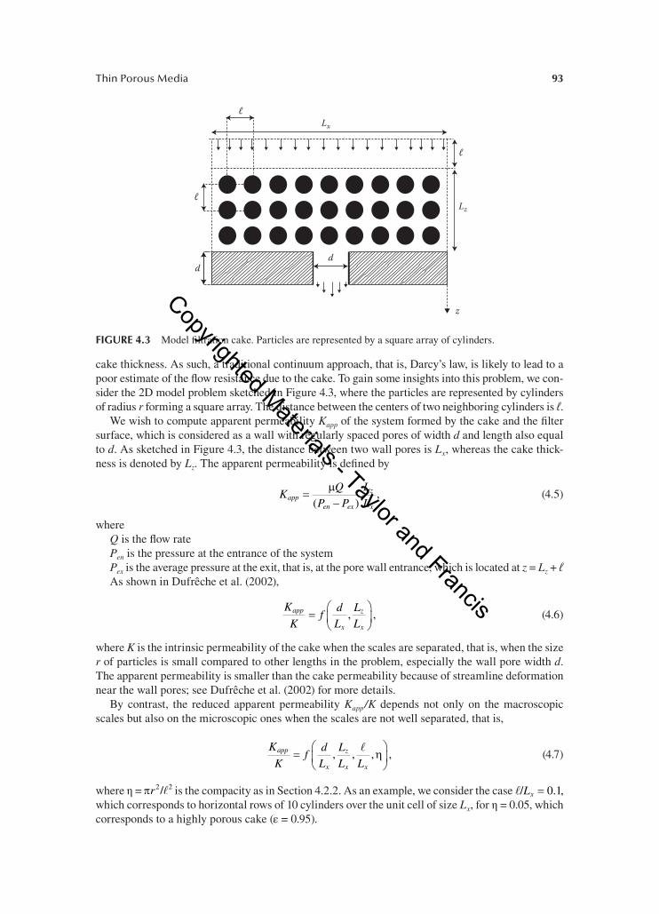
cake thickness. As such, a traditional continuum approach, that is, Darcy’s law, is likely to lead to a poor estimate of the flow resistance due to the cake. To gain some insights into this problem, we con-sider the 2D model problem sketched in Figure 4.3, where the particles are represented by cylinders of radius r forming a square array. The distance between the centers of two neighboring cylinders is ℓ.
We wish to compute apparent permeability Kapp of the system formed by the cake and the filter surface, which is considered as a wall with regularly spaced pores of width d and length also equal to d. As sketched in Figure 4.3, the distance between two wall pores is Lx, whereas the cake thick-ness is denoted by Lz. The apparent permeability is defined by
K
Q
P P
L
Lapp
en ex
z
x
=−µ
( ), (4.5)
whereQ is the flow ratePen is the pressure at the entrance of the systemPex is the average pressure at the exit, that is, at the pore wall entrance, which is located at z = Lz + ℓAs shown in Dufrêche et al. (2002),
K
Kf
d
L
L
Lapp
x
z
x
=
, , (4.6)
where K is the intrinsic permeability of the cake when the scales are separated, that is, when the size r of particles is small compared to other lengths in the problem, especially the wall pore width d. The apparent permeability is smaller than the cake permeability because of streamline deformation near the wall pores; see Dufrêche et al. (2002) for more details.
By contrast, the reduced apparent permeability Kapp /K depends not only on the macroscopic scales but also on the microscopic ones when the scales are not well separated, that is,
K
Kf
d
L
L
L Lapp
x
z
x x
=
, , , ,
� η (4.7)
where η = πr2 2/� is the compacity as in Section 4.2.2. As an example, we consider the case �/ . ,Lx = 0 1 which corresponds to horizontal rows of 10 cylinders over the unit cell of size Lx, for η = 0.05, which corresponds to a highly porous cake (ε = 0.95).
dd
z
Lz
Lx
ℓ
ℓ
ℓ
FIgure 4.3 Model filtration cake. Particles are represented by a square array of cylinders.
Copyrighted Materials - Taylor and Francis

94 Handbook of Porous Media
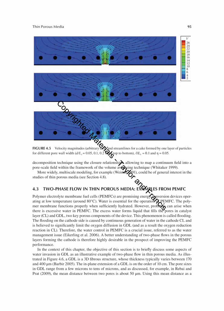
The reduced apparent permeability is shown in Figure 4.4 as a function of the pore wall width. Comparison is made between the values computed from the solution of Stokes equation (considered as reference solution since pore Reynolds number is generally small in the related applications), Brinkman equation, and Darcy equation; see Noel (2006) for the method of solution corresponding to each problem. All the solutions lead to about the same result when d = Lx, that is, when there is no wall. Thus, the entrance/exit effects, which are captured by the Stokes equation but not the Darcy equation, are negligible here. As can be seen, both Brinkman equation and Darcy equation signifi-cantly overestimate the apparent permeability when the cake is very thin (formed by only one row of particles). As shown in Figure 4.5, the overall pressure drop is in fact dominated by the pressure drop in the passage right above the pore wall. This quite localized pressure drop cannot obviously be captured properly by the continuum approaches.
As expected, the discrepancy between the Stokes solution and the continuum approaches decreases as the cake grows. Also, it can be noted that the Brinkman equation leads to better results compared to the Darcy model. This is because the friction on the solid surface of filter is taken into account with the Brinkman equation but not with the Darcy equation. The discrepancy with Stokes solution increases with decreasing wall pore aperture. The picture is similar to the one shown in Figure 4.5. For narrow wall pores, whose size is on the order of one or two particle diameters, the length scale separation is particularly weak, and not surprisingly, the continuum approaches are unable to capture the very localized pressure drop right above the wall pore.
An alternative to the solution of the Stokes equation over the whole computational domain when the cake is not very thin, that is, it is formed by several layers of particles, is to combine continuum model and pore-scale model. This multiscale or hybrid approach consists in solving the Stokes equation in the region of the cake adjacent to the filter inlet, whereas the Darcy model is solved in the region further away from the filter inlet; see Dufrêche et al. (2003) for more details. As reported in Dufrêche et al. (2003), the coupling between the two models can be performed through a domain
0 0.2 0.4 0.6 0.8 1
d/Lx
0
0.2
0.4
0.6
0.8
1
K app
/K
Stokes (1 row)
Darcy (1 row)
Brinkman (1 row)
Stokes (10 rows)
Brinkman (10 rows)
Darcy (10 rows)
FIgure 4.4 Reduced apparent permeability as a function of wall pore width for η = 0.05 and �/ .Lx = 0 1 for a thin porous layer formed by 1 or 10 rows of 10 cylinders.
Copyrighted Materials - Taylor and Francis
95Thin Porous Media
decomposition technique using the closure relationships, allowing to map a continuum field into a pore-scale field within the framework of the volume averaging technique (Whitaker 1999).
More widely, multiscale modeling, for example (Weinan 1991), could be of general interest in the studies of thin porous media (see Section 4.8).
4.3 two-Phase Flow In thIn Porous medIa: examPles From PemFc
Polymer electrolyte membrane fuel cells (PEMFCs) are promising energy conversion devices oper-ating at low temperature (around 80°C). Water is essential for the operation of PEMFC. The poly-mer membrane functions properly when sufficiently hydrated. However, problems can arise when there is excessive water in PEMFC. The excess water forms liquid that fills the pores in catalyst layer (CL) and GDL, two key porous components of the device. This phenomenon is called flooding. The flooding on the cathode side is caused by continuous generation of water in the cathode CL and is believed to significantly limit the oxygen diffusion in GDL (and as a result the oxygen reduction reaction in CL). Therefore, the water control in PEMFC is a crucial issue, referred to as the water management issue (Eikerling et al. 2006). A better understanding of two-phase flows in the porous layers forming the cathode is therefore highly desirable in the prospect of improving the PEMFC performance.
In the context of this chapter, the objective of this section is to briefly discuss some aspects of water invasion in GDL as an illustrative example of two-phase flow in thin porous media. As illus-trated in Figure 4.6, a GDL is a 3D fibrous structure, whose thickness typically varies between 170 and 400 μm (Barbir 2005). The in-plane extension of a GDL is on the order of 10 cm. The pore sizes in GDL range from a few microns to tens of microns, and as discussed, for example, in Rebai and Prat (2009), the mean distance between two pores is about 50 μm. Using this mean distance as a
V2624222018161412108642
FIgure 4.5 Velocity magnitudes (arbitrary unit) and streamlines for a cake formed by one layer of particles for different pore wall width (d/Lx = 0.05, 0.1, 0.2 from top to bottom), �/ .Lx = 0 1 and η = 0.05.
Copyrighted Materials - Taylor and Francis

96 Handbook of Porous Media
unit of length, the GDL thickness is only 4–10 units of length, thus a perfect example of thin system with a lack of length scale separation in the through-plane direction.
A GDL is generally treated with a hydrophobic fluoropolymer so as to render it hydrophobic on the grounds that this improves the PEMFC performances (see Section 4.4). Water that forms in the CL (a porous layer adjacent to the GDL) should be transported through the GDL without blocking the gas transport across the GDL. Hence, roughly, the problem is to evacuate through the GDL the water that forms in excess in the CL while minimizing the impact of liquid water in the pores on the gas access to the CL.
Water invasion in an initially dry hydrophobic porous medium is a drainage process where the invading nonwetting fluid is liquid water and the displaced wetting fluid is gas. Water invasion flow rates are sufficiently low in a PEMFC for the displacement to be analyzed as a quasistatic displace-ment; see Rebai et al. (2009) for a discussion. According to Lenormand et al. (1988), the type of displacement is characterized by the formation of a fractal pattern, referred to as capillary finger-ing. This is illustrated in Figure 4.7. Standard continuum models, based on the concept of relative permeability and retention curve, are unable to simulate correctly this type of displacement for which there is no representative elementary volume (REV) since the phase (liquid–gas) distribution is fractal. Thus, here, there are two good reasons for not using the continuum approach to porous media: (1) the length scale separation is poor for the dry material, and (2) the two-phase invasion pattern is not compatible with a standard continuum modeling.
Among the alternatives to continuum modeling (Perré 2011), pore network (PN) models are par-ticularly well adapted to study two-phase flows in thin systems. As discussed in Joekar-Niasar et al. (2010), they are much less computational time demanding than direct simulations while sufficiently accurate for obtaining valuable results. Thus, here, we consider that the GDL can be represented as a usual network or pores connected by throats. For simplicity, structured networks, that is, square or cubic, are considered.
200 µm Mag= 266×
FIgure 4.6 Example of GDL. (Image courtesy of CEA/LITEN.)
FIgure 4.7 Two-dimensional invasion pattern in a model GDL. The liquid in blue is injected from the bot-tom. Liquid breakthrough occurs at the layer’s top edge.
Copyrighted Materials - Taylor and Francis
97Thin Porous Media
It turns out that the mechanisms leading possibly to the flooding of GDL are not completely delineated. There are two main options: phase change phenomenon (condensation) and invasion directly in liquid phase from the CL. Evaluation of the relative significance of each mechanism is still under study. Here, we simply discuss one aspect of the second scenario, that is, invasion in liquid phase from the adjacent CL. Since the expected invasion regime is capillary fingering, the invasion percolation algorithm (Wilkinson and Willemsen 1983) is well adapted to simulate the water invasion in the network. The distinguishing feature that must be discussed is the bound-ary condition at the inlet. The traditional boundary condition, used, for example, to compute the capillary pressure curve, is to consider that the porous layer is in contact with a liquid reservoir at uniform pressure. This traditional boundary condition seems not to be adapted to the GDL invasion problem.
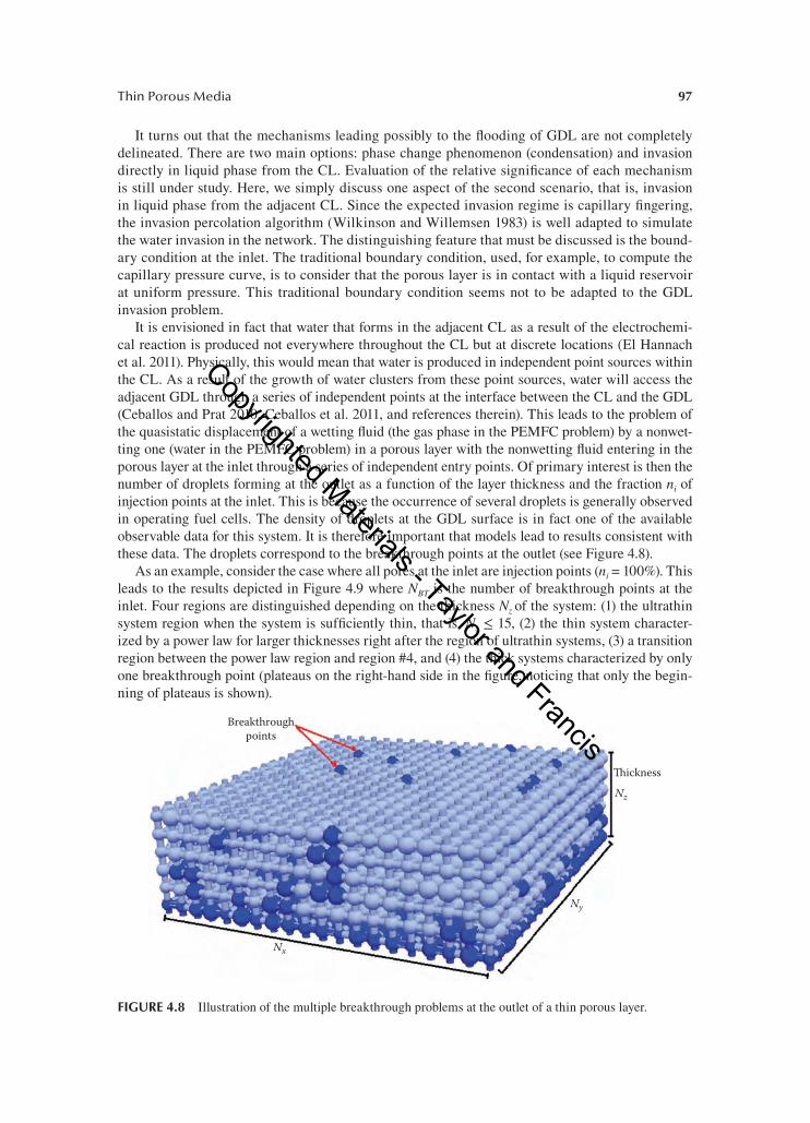
It is envisioned in fact that water that forms in the adjacent CL as a result of the electrochemi-cal reaction is produced not everywhere throughout the CL but at discrete locations (El Hannach et al. 2011). Physically, this would mean that water is produced in independent point sources within the CL. As a result of the growth of water clusters from these point sources, water will access the adjacent GDL through a series of independent points at the interface between the CL and the GDL (Ceballos and Prat 2010, Ceballos et al. 2011, and references therein). This leads to the problem of the quasistatic displacement of a wetting fluid (the gas phase in the PEMFC problem) by a nonwet-ting one (water in the PEMFC problem) in a porous layer with the nonwetting fluid entering in the porous layer at the inlet through a series of independent entry points. Of primary interest is then the number of droplets forming at the outlet as a function of the layer thickness and the fraction ni of injection points at the inlet. This is because the occurrence of several droplets is generally observed in operating fuel cells. The density of droplets at the GDL surface is in fact one of the available observable data for this system. It is therefore important that models lead to results consistent with these data. The droplets correspond to the breakthrough points at the outlet (see Figure 4.8).
As an example, consider the case where all pores at the inlet are injection points (ni = 100%). This leads to the results depicted in Figure 4.9 where NBT is the number of breakthrough points at the inlet. Four regions are distinguished depending on the thickness Nz of the system: (1) the ultrathin system region when the system is sufficiently thin, that is, Nz ≤ 15, (2) the thin system character-ized by a power law for larger thicknesses right after the region of ultrathin systems, (3) a transition region between the power law region and region #4, and (4) the thick systems characterized by only one breakthrough point (plateaus on the right-hand side in the figure, noticing that only the begin-ning of plateaus is shown).
Breakthroughpoints
Nx
Ny
Nz
�ickness
FIgure 4.8 Illustration of the multiple breakthrough problems at the outlet of a thin porous layer.
Copyrighted Materials - Taylor and Francis

98 Handbook of Porous Media
A major conclusion is that the behavior of thin systems is distinct from thicker ones. There is eventually only one breakthrough point in sufficiently thick systems because of the successive merging of various liquid paths emanating from the various injection points. By contrast, several breakthrough points are observed in sufficiently thin systems. As discussed in Ceballos and Prat (2010), the number of breakthrough points for a layer of thickness similar to a GDL thickness is consistent with the droplet density observed in an operating PEMFC (Zhang et al. 2006).
Further results are presented in Ceballos et al. (2011) and Ceballos and Prat (2013).In summary, the illustrative result presented in this section first shows that thin system behavior
can be markedly different from thicker systems. The second major conclusion is that PN mod-els can be very well adapted to the studies of thin systems. They can offer an optimal trade-off between accuracy (no issue of length scale separation) and computational effort. (The results shown in Figure 4.9 are obtained from ensemble averaging over many realizations. It is impossible in prac-tice to perform a similar statistical study from direct simulations, i.e., LBM simulations, etc., owing to the much higher computational times.)
4.4 mIxed wettaBIlIty
Mixed wettability can be an important feature in thin porous media. Mixed wettability refers to sys-tems in which the wettability properties change spatially within the pore space. For instance, some regions of the medium can be hydrophobic, whereas others are hydrophilic. The wettability proper-ties can also change in time as the result, for example, of the interaction with the liquid. A system originally entirely hydrophobic can evolve into a system of a mixed wettability or even become entirely hydrophilic. The change can have a great impact of the transport properties of a thin porous medium. The control of wettability properties can therefore be a crucial issue. This is illustrated in this section from examples related to the PEMFC water management issue.
As discussed in Section 4.3, water invasion in a hydrophobic porous medium in the quasistatic limit that is expected to prevail for flows in fuel cells leads to capillary fingering. By contrast, the invasion pattern is compact in a fully hydrophilic medium (Chapuis et al. 2008). The capillary
0.0001
0.001
0.01
0.1
1Ultrathin �in
1 10Nz
NzNx
Ny
<NBT>/Nx2= 1.24/Nz
2
<NBT>/
Nx2
100
Intermed. �ick
FIgure 4.9 Probability that an outlet bond is a breakthrough point as a function of network thickness Nz
when all inlet bonds are injection bonds (ni = 100%). These results were obtained considering 40 × 40 × Nz
cubic networks, Ceballos et al. (2011).
Copyrighted Materials - Taylor and Francis

99Thin Porous Media
fingering pattern leaves many pores not invaded by the liquid and therefore available for the gas transport. By contrast, the compact invasion pattern blocks rapidly the gas transport across the GDL. This explains why a hydrophobic GDL is a better option.
Suppose now that the layer is entirely hydrophobic when the system starts. Then as illustrated in Figure 4.10a, the gas access across the layer is good because, as just discussed, the capillary finger-ings leave many pores not occupied by the liquid water (the gas access is in fact much better than suggested by Figure 4.10a because the gas access is much better in a 3D network than in the 2D network shown in Figure 4.10a). Suppose a progressive lost of hydrophobic agent carpeting initially the pore walls. Furthermore, assume that the loss of hydrophobic agent is not uniform but randomly localized. Thus, for simplicity, we assume that the wettability can be characterized by the fraction f of pores that are hydrophilic. The fraction of pores still hydrophobic is therefore 1-f. As the result of the increase in the fraction of hydrophilic pores f, the invasion pattern becomes eventually more compact, which can severely limit the gas access. This is schematically illustrated in Figure 4.10b.
As reported in Pulloor Kuttanikkad et al. (2011) and Ceballos and Prat (2013), the somewhat surprising result is that the impact of hydrophobic loss is strongly nonlinear according to this model. This is illustrated in Figure 4.11, which shows the variation of the apparent overall diffusion con-ductivity GD of the whole layer as a function of f. GD is defined by
J AG CD= ∆ , (4.8)
whereJ is the diffusive mass rate through the porous layer when a concentration difference ΔC is
applied across the porous layerA is the in-plane cross-sectional area of the porous layerGD is computed numerically using a PN model
The concentration C0 is imposed in the first plane of pores occupied by the gas phase at the gas inlet (note that the inlet for the gas phase corresponds to the outlet for liquid water), and the
(a)
(b)
FIgure 4.10 Schematic illustration of the impact of a change in wettability. Liquid water (in blue) is injected at the bottom and invades the layer up to break through. The red arrow symbolizes the gas access between the top and bottom edges. The change in wettability in (b) leads to a more compact invasion pattern forming a barrier to the gas access.
Copyrighted Materials - Taylor and Francis

100 Handbook of Porous Media
concentration C0 − ΔC in each pore occupied by the gas at the gas outlet. J is computed from the solution of the diffusion problem over the gas phase under steady-state condition. The computation is made at breakthrough, that is, at the end of water invasion. The results shown in Figure 4.11 were obtained using the invasion percolation algorithm with the reservoir condition at the water inlet for simulating the water invasion. One can refer to Ceballos and Prat (2013) for more details and to Pulloor Kuttanikkad et al. (2011) as regards the method of solution of the diffusion problem over the network.
As can be seen from Figure 4.11, the gas access is in fact not affected by the change in wettabil-ity as long as the fraction f of hydrophilic pores is lower than about 0.7. As discussed in Pulloor Kuttanikkad et al. (2011) and Ceballos and Prat (2013), this value corresponds to the percolation threshold of the hydrophilic PN. Thus, here, a significant change in wettability, that is, f varying from 0 to 0.7, has no effect on the gas access. This can be explained looking at the variation of the water invasion pattern with f as reported in the two aforementioned references. By contrast, the change in wettability has a major impact on gas accesses for f above 0.7, that is, when the network becomes sufficiently hydrophilic for the invasion pattern to become increasingly compact.
The analysis of the change in wettability can also help to analyze aging problems in PEMFC (Pulloor Kuttanikkad et al. 2011).
Naturally, the change in wettability of a given system can be different from that considered in this simple model. For example, the change can occur at smaller scales than the pore scale. The hydrophilic pore localization can also be not random with, for instance, a greater probability in the middle of the layer than at the periphery. The detailed experimental characterization of wettability variation at the scale of the microstructure is in fact an open issue as briefly discussed in Section 4.9.
4.5 thIn Porous-layer assemBly: the concePt oF thIrd layer
Thin porous media are often made of several layers of different properties. For example, the GDL discussed in the previous sections is often used in conjunction with another thin porous medium called the microporous layer (MPL) (Weber and Newman 2005). The bilayer gas diffusion medium (GDM) consists of a coarse GDL coated with a fine MPL. Compared to the GDL, the MPL, com-posed of carbon powder and hydrophobic agent, has smaller pores and a lower porosity. It has been
0.001
GD
/(D/a
)
0.01
0.1Nz = 5
Nz = 11
1
f
0.200.0001
0.4 0.6 0.8 1
FIgure 4.11 Variation of gas-phase diffusive conductance GD as a function of fraction of hydrophilic pores. The computations were performed over a 20 × 20 × Nz network (Nz is the porous-layer thickness mea-sured in lattice spacing unit). D is the binary diffusion coefficient in the free fluid, and a is the lattice spacing (distance between two pores).
Copyrighted Materials - Taylor and Francis

101Thin Porous Media
shown that using the bilayer GDM can increase the fuel cell performance, especially at high current density (Qi and Kaufman 2002). This type of system is illustrated in Figure 4.12.
Diapers are another example of multilayer thin porous media of practical interest (Diersch et al. 2011).There is first a geometry problem. Owing to the fabrication processes, a multilayer thin porous
medium is rarely a simple juxtaposition of different layers. Often there is interpenetration between the various layers (see Figure 4.13b). For instance, the grains of the carbon powder used to make the MPL can penetrate into the larger pores of the GDL. This leads to envision a bilayer thin porous medium as in fact as a three-layer porous medium, where the third layer is the transition region at the interface between the two layers. The extension of the concept to multilayer thin porous media is straightforward. We only consider bilayer systems in this chapter.
An illustrative example is given in Figure 4.13. The technique to generate this type of bilayer cel-lular porous medium is a simple extension of the methods described in Gostick (2013) for a single layer. As can be seen from Figure 4.13a, the interface between the two layers forms here an ultrathin intermediate porous layer with pores of intermediate size.
The importance of the third layer can be also illustrated as follows. As depicted in Figure 4.14, suppose the presence of a defect in the transition region between the two layers. The defect can be a single big pore or a collection of big pores larger than the pores in both the adjacent fine and coarse porous layers or a collection of hydrophilic pores. As an example, consider again the quasistatic inva-sion process of liquid water in the system depicted in Figure 4.14 assuming hydrophobic pores every-where except in the defect region where the pores are hydrophilic. The invasion capillary threshold of the pores in the defect being smaller than the ones of other pores, the result is the preferential filling
MPL
GDL
FIgure 4.12 Computer-generated model of bilayer thin porous medium.
(a)
FIgure 4.13 Bilayer thin porous medium model. (a) A porous layer with large pores is in contact with a layer with smaller pores. The interface between the two layers forms an intermediate porous layer with pores of intermediate size. The blue cells are pores invaded by a nonwetting fluid injected at the bottom of the bilayer system. (Continued)
Copyrighted Materials - Taylor and Francis

102 Handbook of Porous Media
(b)
FIgure 4.13 (continued) Bilayer thin porous medium model. (b) Illustration of the interpenetration between a fibrous layer with small pores (in blue) and a coarser fibrous layer (in red).
(a1) (a2)
(b1) (b2)
(c1) (c2)
FIgure 4.14 Influence of a defect (in red) on the invasion pattern at breakthrough (in blue) in a bilayer thin porous system. Water (in blue) is injected at the bottom. (Continued)
Copyrighted Materials - Taylor and Francis

103Thin Porous Media
of the defect. This is illustrated in Figure 4.14 for a defective region of increasing size. The defective region is shown in red in Figure 4.14. The defective zone was created in this example by positioning an ellipse of increasing size at the interface between the two media. All pores contained in the ellipse were considered as hydrophilic. We again consider a slow (quasistatic) invasion from the bottom edge and use the standard invasion percolation algorithm. To take into account the defective zone, we sim-ply impose a very small capillary invasion threshold in all pores located in the defective zone. This leads to the preferential invasion of the defective zone as soon as the liquid reaches the periphery of the defective zone. As can be seen from Figure 4.14, the presence of the defect can first modify the location of the breakthrough point (e.g., compare Figure 4.14a and c).
Suppose we are again interested in the gas transfer. The partial flooding of the third layer can obviously have a detrimental consequence on the gas access between the top and bottom edges of system and thus the performance of the system using this type of bilayer thin porous medium. The gas transfer is characterized from the computation of the overall gas diffusion conductivity similarly as in Section 4.4 (see Equation 4.8 and the associated text in Section 4.4). The results cor-responding to the various patterns shown in Figure 4.14 are presented in Table 4.1.
(d1) (d2)
(e1) (e2)
FIgure 4.14 (continued) Influence of a defect (in red) on the invasion pattern at breakthrough (in blue) in a bilayer thin porous system. Water (in blue) is injected at the bottom.
taBle 4.1liquid saturation (S) and overall gas diffusion conductivity corresponding to the Various Patterns shown in Figure 4.14. GDref Is the conductivity in the absence of defect (Figure 4.14a)
Pattern S GD/GDref
Figure 4.14a 0.142 1
Figure 4.14b 0.142 1
Figure 4.14c 0.176 0.87
Figure 4.14d 0.161 0.96
Figure 4.14e 0.204 0.79
Copyrighted Materials - Taylor and Francis

104 Handbook of Porous Media
As expected, the gas conductivity globally decreases as the defect size increases. However, the variation can be nonmonotonous as indicated in Table 4.1. This can be easily explained from the variation of saturation and the liquid invasion pattern. For example, compare the invasion pat-tern in the bottom fine layer between Figure 4.14c and d. The fine layer is clearly less invaded in Figure 4.14d compared to Figure 4.14c. This explains the increase in the gas diffusion conductivity between the situation corresponding to Figure 4.14c and the one corresponding to Figure 4.14d. The change in the invasion pattern is a consequence of the change in the capillary invasion threshold occurring in the pores of the fine layer located in the interfacial region between the two layers when they become pores belonging to the defective zone.
In this section, we briefly discussed the concept of third layer, that is, the possible transition region forming the interface between two thin porous layers in contact. The impact of the so-called third layer was illustrated through PN simulations of two-phase flow in the quasistatic limit and the computation of the diffusive transport in the region free of liquid. Naturally, many other trans-port processes can be of interest, and other modeling techniques are certainly worth considering depending on the process to be studied. Regarding the modeling aspect, the works dedicated to the study of transport phenomena at the interface between two porous media or a porous medium and a free fluid could be a source of inspiration (D’Hueppe et al. 2012, Jamet et al. 2009, and refer-ences therein).
4.6 thIn Porous medIa and lIquId FIlm Flows
To illustrate the possible impact of liquid film flows on transfers in a thin porous medium, we con-sider the problem of slow drying of a thin porous layer initially fully saturated by a wetting liquid. Drying is ubiquitous in industry and one of the most energy-consuming unit operations (Plumb 2000). This holds also for thin porous media. For instance, the teflonization process rendering hydrophobic the GDL evoked in previous sections usually involves a drying step. Drying processes have been the subject of many works. Among the advances made over the last decade is the full recognition that liquid film flows can have a major impact on the drying process (Yiotis et al. 2004, Prat 2007, Chauvet et al. 2009, Yiotis et al. 2012). They notably contribute to significantly extend the duration of the period of intense evaporation, referred to as the constant rate period (Plumb 2000). This is so because the hydraulic connectivity to the surface is maintained via the liquid films, even when the bulk-phase connectivity ends. Also the films can be a vector for transporting species, colloidal particles, ions, etc., up to the surface of porous medium (Camassel et al. 2005).
The fact that the liquid films can extend over a significant region of a drying porous medium is illustrated in Figure 4.15. As can be seen, the liquid film region is by far the region of largest spatial extent in this example.
Dry region Liquid �lm region Liquidsaturatedregion
FIgure 4.15 Phase distribution within a thin porous layer drying from the left-hand side. This medium consists of a monolayer of glass beads sandwiched between two glass plates.
Copyrighted Materials - Taylor and Francis

105Thin Porous Media
As discussed in Chauvet et al. (2009), the extended liquid films are controlled by the competition between the capillary forces, the viscous forces generated by the liquid flow within the films, and the gravity forces. In a thin medium, gravity forces can be expected to be negligible. Therefore, the extent of the films is expected to be controlled by the competition between viscous forces and capil-lary forces. According to the currently available model of liquid films in a drying porous medium (Yiotis et al. 2004, Prat 2007), the maximum extent Lf of film regions for a perfectly wetting liquid can be estimated as
L
rf Caf ≈ − − −1 1 3χ , (4.9)
wherer is a mean pore sizeχ = 1.885f = 528
Ca = 3µ ρ γj/ � where j, μ, γ, and ρ� are the evaporation flux, the liquid dynamic viscosity, surface tension, and liquid density, respectively
A typical evaporation flux for water at the room temperature is on the order of 1 cm/day. This corresponds to j ≈ 10−4 kg/m2/s. Application of Equation 4.9 then leads to the result shown in Figure 4.16. In accordance with Equation 4.9, the maximum size of film region varies linearly with the mean pore size. As can be seen from Figure 4.16, Lf varies about between 6 mm and 6 m when the mean pore size varies between 0.1 and 100 μm. Since the thickness of a thin porous medium is typically less than 1 mm in many applications, thus shorter than Lf, this result shows that the hydraulic conductivity to the surface of porous medium will be maintained via liquid films over practically all drying duration in such systems. Thus, it is expected that slow drying of thin porous media will be essentially characterized by a long constant rate period over which all pores will be eventually invaded in the bulk by the gas phase. After this constant rate period, a very short falling rate period corresponding to the evaporation of liquid films still present all over the pore space at the end of the constant rate period is expected. The falling rate period is expected to be short for two reasons: (1) the liquid mass corresponding to the films is small compared to the mass of liquid initially present in the medium, and (2) the external mass transfer length scale (the mass external
0.1
0.01
0.1
1
1 10010
r (μm)
L f (
m)
FIgure 4.16 Film region maximum size as a function of pore mean radius for an evaporation flux of 1 cm/day.
Copyrighted Materials - Taylor and Francis

106 Handbook of Porous Media
boundary layer typically) is typically greater than the thickness of the medium (this implies that the mass transfer resistance due to the receding of film tips within the medium is weak compared to the external mass transfer resistance).
It must be pointed out that Equation 4.9 gives an overestimate of the film region maximum size. Depending on the contact angle, pore space geometry, evaporation rate (the film extent is inversely proportional to the evaporation rate), etc., the extent of film regions might be less than anticipated from Equation 4.9. However, this does not change the main conclusion since Lf in Figure 4.16 is much greater than the expected thickness of typical thin porous media.
In summary, while liquid films can be often ignored in thick porous media because the main phases of drying are dominated by the changes in the hydraulic connectivity of the network formed by the fully saturated pores, the situation can be completely different in thin porous media with drying kinetics entirely controlled by the liquid films.
4.7 ImPact oF a thIn salt crust on dryIng
Here, we consider the special case where the liquid solution saturating a (thick) porous medium is an aqueous solution containing a dissolved salt (sodium chloride in what follows). The considered situation is sketched in Figure 4.17. As discussed in Hidri et al. (2013), this is a subject of interest in relation with soil physics, the underground storage of CO2, civil engineering issues, and the protec-tion of our cultural heritage, the latter because of the damages that can be induced in a porous mate-rial by the salt crystallization process. In the context of this chapter, this particular drying situation is interesting because the drying process can result in the formation of a thin porous medium at the top of the underlying porous material. Thus, this is an example of self-generation of a thin porous medium on top of a thick porous medium. The fact that the precipitation of the salt occurs on top, that is, at the evaporative surface of the porous medium, is well understood (Hidri et al. 2013 and references therein). The ions are transported by the flow induced in the liquid phase by the evapora-tion process. This flow is directed toward the evaporation surface where the ions accumulate until the ion concentration marking the onset of crystallization is reached. Then the salt precipitation continues, and salt efflorescence develops at the porous medium surface. As reported in Eloukabi et al. (2013) and Dueñas Velasco et al. (2013), two main types of efflorescence can be distinguished, namely, crusty and patchy. As sketched in Figure 4.17b, the crusty efflorescence forms a thin salt crust eventually covering all the surface of the porous medium. By contrast, the patchy efflores-cence only partially covers the porous medium surface and is characterized by the formation of well-individualized crystallized salt structures. The impact of the two types of efflorescence on evaporation is quite different. The patchy efflorescence leads to evaporation rates comparable to the ones observed for pure water, whereas, as shown in Figure 4.18, the development of salt crust severely reduces the evaporation rate.
Evaporation
Porousmedium
Salt crust
(a) (b)
FIgure 4.17 Sketch of drying situation discussed in this section.
Copyrighted Materials - Taylor and Francis

107Thin Porous Media
The crust is in fact not compact but forms a thin porous medium. As shown in Figure 4.19, the average thickness of the crust formed in the experiment discussed in this section is on the order of 500 μm. Crust internal porous structure is not known, and its characterization is one the numerous open questions in this field.
In summary, the salt crust discussed in this section has a great impact on the drying process. The evaporation rate is considerably reduced compared to pure water drying. The crust is an example of thin porous medium, whose internal porous structure is in fact not known. This piece of information is, however, crucial if one wishes to explain the observed evaporation rate reduction. More widely, this poses the question of the characterization of thin porous media. This point is briefly discussed in more details in Section 4.9.
In addition to the previously mentioned references, the reader interested in this problem can also refer to Veran-Tissoires et al. (2012a,b), Veran-Tissoires and Prat (2014), Gupta et al. (2014), and references therein.
4.8 BrIeF reVIew oF other sItuatIons InVolVIng tPm
In addition to the examples considered in previous sections, thin porous media are encountered in many other situations. Some of them are evoked in this section. Porous-layer coatings are a good example of thin porous media developed for improving heat transfer performance (Liter and
20000
0.1
0.2
0.3
0.4 Pure water
NaCl solution
0.5
400 600Time (min)
Evap
orat
ed m
ass (
g)
800 1000 1200 1400
FIgure 4.18 Evaporated mass as a function of time. Comparison between a sample initially saturated with pure water (solid line) and the same sample initially saturated with a nearly saturated NaCl solution (dashed line). These results were obtained with a porous medium consisting of sintered glass beads. The porous cyl-inder is 10.0 mm ± 0.2 mm long and has a diameter of 10.0 mm ± 0.25 mm. The pore sizes are distributed in the range 1.0–1.6 μm; see Dueñas Velasco et al. (2013) for more details.
–2
Z
YX
–4–6
13.012.812.612.412.212.011.8
FIgure 4.19 Topography obtained by x-ray tomography along a vertical slice of the crust formed in the experiment described in the caption of Figure 4.18; the figures along the z-axis are in millimeters; see Dueñas Velasco et al. (2013) for more details.
Copyrighted Materials - Taylor and Francis
108 Handbook of Porous Media
Kaviany 2001). The porous layers considered in Liter and Kaviany (2001) are typically formed by conical particle stacks. Each cone is less than 10 particle diameters in height. This type of coating can be very effective with an enhancement of the critical heat flux by a factor of three compared to a flat surface.
Another problem having received quite a lot of attention is the absorption of droplets in thin media (e.g., printing). The last stage of the ink-jet printing process, the spreading and solidification of droplets on a substrate, determines to a large extent the final print quality. In this context, the development of numerical codes aiming at simulating the printing process can be regarded as an important development tool for next generations of the ink-jet printing technology (Markicevic and Navaz 2010, Siregar et al. 2013, and references therein). Naturally, there are also basic questions that need to be answered (Shikhmurzaev and Sprittles 2013).
Beyond the droplet problem, the various operations involved in the processing of paper are also a source of interesting problems (Iliev et al. 2012, Karlsson 2000, and references therein).
Hygiene products, such as diapers and wipes, are also a subject of investigations (Mirnyy et al. 2013). Often the transport problem in a thin porous medium cannot be decoupled from the problem of the deformation of the porous layer(s) (Mirnyy et al. 2013). This is often the case with the paper or hygiene product–related problems. Deformation of the layers can be also an issue in PEMFC (Lin et al. 2008). Owing to their small thickness, thin porous media can often deform easily. Thus, deformation of thin porous media can be regarded as a quite important issue, not only from a purely mechanical standpoint (Taber 1992), but also because of the impact of deformation on transport phenomena.
Textiles and associated processes are also a source of interesting thin porous media–related problems. This has long been identified (Cassie 1944), and this field is still a very active domain of innovative research (Yang et al. 2010). Thin porous media are also encountered in thermal insula-tion systems (Fricke et al. 2006, Arambakam et al. 2014).
Some bioengineering-related problems can also be considered as good examples of thin porous media problems. This notably includes the porous coatings used in order to increase the attachment of bone to metal implants (Hanzlik and Day 2013) or biomechanics problem at the scale of arterial walls, which can be addressed using techniques similar as for other classes of thin porous media (Chung and Vafai 2013).
This short list is of course far from being exhaustive.
4.9 research oPPortunItIes
Research opportunities in the domain of thin porous media are numerous for several reasons. Firstly, specific applications, for example, fuel cells, filters, and hygiene products, are of course themselves often very interesting. Secondly, the field is king of emerging as a well-identified research field. This means that trying to identify theoretical, numerical, or experimental techniques or specific problems of common interest to various applications involving thin porous media is recognized as a specific field of interest. For instance, tools developed for the study of a specific application can be of wider interest and worth considering for other situations involving thin porous media. Thirdly, the fact that the porous medium is thin can be an advantage. For instance, direct numerical simulations at pore scale can be performed only over a small region of an ordinary porous sample because of the computational cost. When the system is only a few pore sizes thick, the use of direct simulations can be a possible option for understanding and characterizing transport processes at the scale of the whole system, that is, over its entire thickness. The same holds of course for less computational time demanding techniques, such as PN simulations. This was illustrated in Section 4.3. This is in contrast with the ordinary porous media where the PN simulations are often used only to compute the mac-roscopic parameters, that is, the relative permeabilities or the retention curve, involved in the Darcy’s scale equations (Blunt et al. 2002). Similarly, the modern imaging techniques, such as x-ray microto-mography, can image a given thin material over its whole thickness (Rolland du Roscoat et al. 2007).
Copyrighted Materials - Taylor and Francis

109Thin Porous Media
There are many open scientific problems associated with the study of thin porous media. Some of them are in fact not specific to thin porous media. For example, fibrous materials are often encountered in thin porous systems. The GDLs of PEMFC, textiles, and paper are just three obvi-ous examples. Yet the question of the modeling of two-phase flow in fibrous materials using the PN technique is generic and not specific to thin porous media. Despite recent advances (Gostick 2013), this is still a subject of controversy. The microstructure of a fibrous material is obviously quite different from the microstructures of mineral rocks or packings of particles mostly considered in previous works on PN modeling. The applicability of traditional PN modeling concepts to fibrous materials is therefore a question.
Naturally, there are also many specific questions. For example, it is often not possible to use an experimental setup designed for ordinary porous samples in order to characterize a thin porous medium. An example is the characterization of the retention curve of GDL. Specific setups must be developed (Gostick et al. 2008). A yet not-well-solved issue is the characterization of wettability of thin porous media, especially when the system is of mixed wettability. GDLs are most probably an example of thin porous media of mixed wettability in spite of its treatment by a hydrophobic agent. Methods can be used to characterize its mean apparent contact angle (Gurau et al. 2006). By contrast, although this piece of information would be extremely useful to modelers, the experimental character-ization of the wettability variations at smaller scales within the GDL is out of reach for the moment.
On the modeling side, the lack of length scale separation over the thickness can require the development of specific models. When the lack of length scale separation is not an issue, the fact that the thickness is much smaller than the other dimensions can motivate specific modeling upscal-ing studies (Feng and Weinbaum 2000, Qin and Hassanizadeh 2014). Often there are also in-plane heterogeneities that need appropriate modeling to be taken into account properly.
In some multilayer thin systems, such as a PEMFC, a continuum approach can be acceptable in one layer, whereas another approach, PN modeling or direct simulation for instance, is more suitable in an adjacent layer. This type of situation requires combining models expressed at different scales. As mentioned in Section 4.2, this can be done using mixed or hybrid numerical methods; see, for instance, Sun et al. (2012) and references therein.
In brief, thin porous media can be regarded as a widely open field for innovative experimental, numerical, and theoretical studies. To a certain extent, thin porous media can be even regarded as a (virtual) laboratory for testing innovative methods whose development can be in fact motivated by the studies of thick/ordinary porous media. A given method can be tested with reduced computa-tional times owing to the small size of thin porous media in the through-plane direction.
4.10 conclusIons
Thin porous media are first interesting because they often behave differently than thicker porous media. This was illustrated through the droplet formation problem discussed in Section 4.3. This is often so because some physical phenomena whose impact is weak or even negligible in an ordinary porous medium can become dominant in a thin medium. Liquid films in drying are an example (see Section 4.6).
As discussed in this chapter, thin porous media are encountered in many applications. Each application, for example, PEMFC, paper printing, porous coatings, insulation, and filters, possesses its own specificities, scientific questions, and bottlenecks.
However, thin porous media are also emerging as a specific research area encompassing the vari-ous applications. This is so because experimental, numerical, and theoretical problems of common interest can be identified. The possible lack of length separation over the medium thickness, the problem of coupling models at different scales, the need of developing models taking advantage of the small ratio between the medium thickness and the other spatial dimensions, the inherent in-plane and through-plane heterogeneities, the possible existence of defects between layers in multilayer thin media, and swelling and shrinking phenomena are just a few examples of generic problems.
Copyrighted Materials - Taylor and Francis

110 Handbook of Porous Media
Thin porous media are also in fact of wider interest because they offer excellent opportunities to develop and test innovative methods. Hybrid methods, that is, coupling models at various scales, are an example.
acknowledgments
The first author (M.P.) is thankful to the students and colleagues he has worked with over the years on thin porous media–related problem. Their contribution is greatly appreciated. Works on PEMFC have been developed in close collaboration with J. Pauchet from CEA. His contribution and support are also greatly appreciated. Financial supports for PEMFC-related studies from GIP ANR (Project No. ANR-06-PANH-022-02 “Chameau”), CEA, and CNRS are gratefully acknowledged.
reFerences
Arambakam, R., H. Vahedi Tafreshi, and B. Pourdeyhimi. 2014. Modeling performance of multi-component fibrous insulations against conductive and radiative heat transfer. International Journal of Heat and Mass Transfer 71: 341–348.
Barbir, F. 2005. PEM Fuel Cells: Theory and Practice. Elsevier Academic Press, Amsterdam, the Netherlands.Blunt, M.J., M.D. Jackson, M. Piri, and P.H. Valvatne. 2002. Detailed physics, predictive capabilities and
macroscopic consequences for pore-network models of multiphase flow. Advances in Water Resources 25: 1069–1089.
Camassel, B., N. Sghaier, M. Prat, and S. Ben Nasrallah. 2005. Ions transport during evaporation in capillary tubes of polygonal cross section. Chemical Engineering Science 60: 815–826.
Cassie, A.B.D. 1944. Physics and textiles. Reports of Progress in Physics 10: 141–171.Ceballos, L. and M. Prat. 2010. Invasion percolation with multiple inlet injections and the water management
problem in proton exchange membrane fuel cells. Journal of Power Sources 195: 825–828.Ceballos, L. and M. Prat. 2013. Slow invasion of a fluid from multiple inlet sources in a thin porous layer:
Influence of trapping and wettability. Physical Review E 87: 043005.Ceballos, L., M. Prat, and P. Duru. 2011. Slow invasion of a nonwetting fluid from multiple inlet sources in a
thin porous layer. Physical Review E 84: 056311.Chapuis, O., M. Prat, M. Quintard, E. Chane-Kane, O. Guillot, and N. Mayer. 2008. Two-phase flow and
evaporation in model fibrous media. Application to the gas diffusion layer of PEM fuel cells. Journal of Power Sources 178: 258–268.
Chauvet, F., P. Duru, S. Geoffroy, and M. Prat, 2009, Three periods of drying of a single square capillary tube. Physical Review Letters 103: 124502.
Chauvet, F., S. Geoffroy, A. Hamoumi, M. Prat, and P. Joseph. 2012. Role of gas in capillary filling of nanoslits. Soft Matter 8: 10738.
Chung, S. and K. Vafai. 2013. Low-density lipoprotein transport within a multi-layered arterial wall-effect of the atherosclerotic plaque/stenosis. Journal of Biomechanics 46: 574–585.
D’Hueppe A., M. Chandesris, D. Jamet, and B. Goyeau. 2012. Coupling a two-temperature model and a one-temperature model at a fluid-porous interface. International Journal of Heat and Mass Transfer 55: 2510–2538.
Diersch, H.-J.G., V. Clausnitzer, V. Myrnyy, R. Rosati, M. Schmidt, H. Beruda, B.J. Ehrnsperger, and R. Virgilio. 2011. Modeling unsaturated flow in absorbent swelling porous media: Part 2. Numerical simulation. Transport in Porous Media 86: 753–776.
Dueñas Velasco, M., P. Duru, M. Marcoux, and M. Prat. 2013. Efflorescence fairy ring and salt centripetal colonization at the surface of a drying porous medium containing a salt solution. Impact on drying curve. Proceedings of Eurodrying’2013, Paris, France, October, 2–4.
Dufrêche, J., M. Prat, and P. Schmitz. 2003. A two–scale domain decomposition method for computing the flow through a porous layer limited by a perforated plate. International Journal Numerical Methods in Fluids 42: 623 –639.
Dufrêche, J., M. Prat, P. Schmitz, and J.D. Sherwood. 2002. On the apparent permeability of a porous layer backed by a perforated plate. Chemical Engineering Science 57: 2933–2944.
Eikerling, M., A.A. Kornyshev, and A.R. Kucernak. 2006. Water in polymer electrolyte fuel cells: Friend or foe? Physics Today 59 (10): 38–44.
Copyrighted Materials - Taylor and Francis

111Thin Porous Media
El Hannach, M., M. Prat, and J. Pauchet. 2011. Pore network modelling: Application to multiphase trans-port inside the cathode catalyst layer of proton exchange membrane fuel cell. Electrochimica Acta 56: 10796–10808.
Elimelech, M., X. Jia, J. Gregory, and R. William. 1995. Particle Deposition & Aggregation: Measurement, Modelling and Simulation. Butterworth-Heinemann, Boston, MA.
Eloukabi, H., N. Sghaier, S. Ben Nasrallah, and M. Prat.2013. Experimental study of the effect of sodium chloride on drying of porous media: The crusty-patchy efflorescence transition. International Journal of Heat and Mass Transfer 56: 80–93.
Feng J. and S. Weinbaum. 2000. Lubrication theory in highly compressible porous media: The mechanics of skiing, from red cells to humans. Journal of Fluid Mechanics 422: 281–317.
Fricke, J., H. Schwab, and U. Heinemann. 2006. Vacuum insulation panel-exciting thermal properties and most challenging applications. International Journal Thermophysics 27: 1123–1139.
Gostick, J.T. 2013. Random pore network modeling of fibrous PEMFC gas diffusion media using Voronoi and Delaunay tessellations. Journal of the Electrochemical Society 160 (8): F731–F743.
Gostick, J.T., M.A. Ioannidis, M.W. Fowler, and M.D Pritzker. 2008. Direct measurement of the capillary pressure characteristics of water–air–gas diffusion layer systems for PEM fuel cells. Electrochemistry Communications 10: 1520–1523.
Gupta, S., H. Huinink, M. Prat, L. Pel, and K. Kopinga. 2014. Paradoxical drying due to salt crystallization. Chemical Engineering Science.
Gurau, V., M.J. Bluemle, E.S. De Castro, Y.-M. Tsou, J.A. Mann Jr., and T.A. Zawodzinski Jr. 2006. Characterization of transport properties in gas diffusion layers for proton exchange membrane fuel cells 1. Wettability (internal contact angle to water and surface energy of GDL fibers). Journal of Power Sources 160: 1156–1162.
Hanzlik, J.A. and J.S. Day. 2013. Bone ingrowth in well-fixed retrieved porous tantalum implants. The Journal of Arthroplasty 28: 922–922.
Hidri, F., N. Sghaier, H. Eloukabi, M. Prat, and S. Ben Nasrallah. 2013. Porous medium coffee ring effect and other factors affecting the first crystallization time of sodium chloride at the surface of a drying porous medium. Physics of Fluids 25: 127101.
Iliev, O., G. Printsypar, and S. Rief. 2012. On mathematical modeling and simulation of the pressing section of a paper machine including dynamic capillary effects: One-dimensional model. Transport in Porous Media 92: 41–59.
Jamet, D., M. Chandesris, and B. Goyeau. 2009. On the equivalence of the discontinuous one- and two-Domain Approaches for the modeling of transport phenomena at a fluid/porous interface. Transport in Porous Media 78 (3): 419–438.
Joekar-Niasar, V., S.M. Hassanizadeh, and H. Dahle. 2010. Dynamic pore-network modeling of drainage in two-phase flow. Journal of Fluid Mechanics 655: 38–71.
Karlsson, M. 2000. Drying. Chapter 9 in Papermaking Science and Technology: Papermaking Part 2. Published by Finnish Engineers’ Association and Tappi.
Lenormand, R., E. Touboul, and C. Zarcone. 1988. Numerical models and experiments on immiscible displace-ments in porous media. Journal of Fluid Mechanics 189: 165–187.
Levy, T. 1981. Loi de Darcy ou loi de Brinkman? C.R.Acad.Sci. Paris Série II 292: 872–874.Lin, J., W. Chen, Y. Su, and T. Ko. 2008. Effect of gas diffusion layer compression on the performance in a
proton exchange membrane fuel cell. Fuel 87 (12): 2420–2424.Litter, S.G. and M. Kaviany. 2001. Pool boiling CHF enhancement by modulated porous-layer coating: Theory
and experiment. International Journal of Heat and Mass Transfer 44: 4287–4311.Markicevic, B. and H.K. Navaz. 2010. The influence of capillary flow on the fate of evaporating wetted imprint
of the sessile droplet in porous medium. Physics of Fluids 22: 122103.Mirnyy V., V. Clausnitzer, H.J.G. Diersch, R. Rosati, M. Schmidt, and H. Beruda. 2013. Wicking in absorbent
swelling porous materials. Chapter 7 in Wicking in Porous Materials: Traditional and Modern Modeling Approaches, eds. R. Masoodi and K.M. Pillai. CRC Press/Taylor & Francis, Boca-Raton, FL.
Nield, D.A. and A. Bejan. 1992. Convection in Porous Media. Springer-Verlag, NewYork.Noel, F. 2006. Simulation directe d’écoulements à travers un réseau d’obstacles situé près d’une singularité de
paroi. Application à la filtration. PhD dissertation, INPT.Perré, P. 2011. A review of modern computational and experimental tools relevant to the field of drying. Drying
Technology 29 (13): 1529–1541.Plumb, O.A. 2000. Transport phenomena in porous media: Modeling the drying process. In Handbook of
Porous Media, ed. K. Vafai. Marcel Dekker, NewYork.
Copyrighted Materials - Taylor and Francis

112 Handbook of Porous Media
Prat, M. 2007. On the influence of pore shape, contact angle and film flows on drying of capillary porous media. International Journal of Heat and Mass Transfer 50: 1455–1468.
Pulloor Kuttanikkad, S., M. Prat, and J. Pauchet. 2011. Pore-network simulations of two-phase flow in a thin porous layer of mixed wettability: Application to water transport in gas diffusion layers of proton exchange membrane fuel cells. Journal of Power Sources 196: 1145–1155.
Qi, Z. and A. Kaufman. 2002. Improvement of water management by a microporous sublayer for PEM fuel cells. Journal of Power Sources 109: 38–46.
Qin, C.Z. and S.M. Hassanizadeh. 2014. Multiphase flow through multilayers of thin porous media: General balance equations and constitutive relationships for a solid–gas–liquid three-phase system. International Journal of Heat and Mass Transfer 70: 693–708.
Rebai, M. and M. Prat. 2009. Scale effect and two-phase flow in a thin hydrophobic porous layer. Application to water transport in gas diffusion layers of PEM fuel cells. Journal of Power Sources 192: 534–543.
Rolland du Roscoat, S., M. Decain, X. Thibault, C. Geindreau, and J.-F. Bloch. 2007. Estimation of micro-structural properties from synchrotron x-ray microtomography and determination of the REV in paper materials. Acta Materialia 55: 2841–2850.
Sangani, A.S. and A. Acrivos. 1982. Slow flow past periodic arrays of cylinders with application to heat trans-fer. International Journal of Multiphase Flow 8: 193–206.
Shikhmurzaev, Y.D. and J.E. Sprittles. 2013. Dynamic contact angle of a liquid spreading on an unsaturated wettable porous substrate. Journal of Fluid Mechanics 715: 273–282.
Siregar, D.P., J.G.M. Kuerten, and C.W.M. van der Geld. 2013. Numerical simulation of the drying of inkjet-printed droplets. Journal of Colloid and Interface Science 392: 388–395.
Sun, T., Y. Mehmani, and M.T. Balhoff. 2012. Hybrid multi scale modeling through direct substitution of pore-scale models into near-well reservoir simulators. Energy & Fuels 26 (9): 5828–5836.
Taber, L.A. 1992. A Theory for transverse deflection of poroelastic Plates. Journal of Applied Mechanics 59: 628–634.
Tsay, R.-Y. and S. Weinbaum. 1991. Viscous flow in a channel with periodic cross-bridging fibres: Exact solu-tions and Brinkman approximation. Journal of Fluid Mechanics 226: 125–148.
Veran-Tissoires, S., M. Marcoux, and M. Prat. 2012a. Discrete salt crystallization at the surface of a porous medium. Physical Review Letters 108: 054502.
Veran-Tissoires, S., M. Marcoux, and M. Prat. 2012b. Salt crystallization at the surface of a heterogeneous porous medium. Europhysics Letters 98: 34005.
Veran-Tissoires, S. and M. Prat. 2014. Evaporation of a sodium chloride solution from a saturated porous medium with efflorescence formation. Journal of Fluid Mechanics 749: 701–749.
Weber, A.Z. and J. Newman. 2005. Effects of microporous layers in polymer electrolyte fuel cells. Journal of the Electrochemical Society 152: A677–A688.
Weinan, E. 2011. Principles of Multiscale Modeling, 1st edn. Cambridge University Press, Cambridge, U.K.Whitaker, S. 1999. The Method of Volume Averaging. Kluwer Academic Publishers, Dordrecht, the Netherlands.Wilkinson, D. and J.F. Willemsen. 1983. Invasion percolation: A new form of percolation theory. Journal of
Physics A: Mathematical and General 16: 3365–3376.Yang, Y.-L., M.-C. Chuang, S.-L. Lou, and J. Wang. 2010. Thick-film textile-based amperometric sensors and
biosensors. Analyst 135: 1230–1234Yiotis, A.G., A.G. Boudouvis, A.K. Stubos, I.N. Tsimpanogiannis, and Y.C. Yortsos. 2004. The effect of liquid
films on the drying of porous media. AIChE Journal 50 (11): 2721–2737.Yiotis, A.G., D. Salin, E.S. Tajerand, and Y.C. Yortsos, 2012. Drying in porous media with gravity-stabilized
fronts: Experimental results. Physical Review E 86: 026310.Zhang, F.Y., X.G. Yang, and C.Y Wang. 2006. Liquid water removal from a polymer electrolyte fuel cell.
Journal of the Electrochemical Society 153 (2): A225–A232.
Copyrighted Materials - Taylor and Francis