Mapping Guide for a European Urban Atlas
36
GSE Land Document-No. ITD-0421-GSELand-TN-01 Infoterra GmbH Version: I1.02 Date: 08.05.2008 © GSE Land Consortium Page: 1 of 36 Mapping Guide for a European Urban Atlas ITD-0421-GSELand-TN-01 Issue 1.02 GSE Land Information Services ESRIN/Contract No. 19407/05/I-LG Stage 2 of the Earthwatch GMES Service Element Scaling Up Consolidated GMES Services Author: Susanne Meirich Contributor: GSE Land Consortium
Transcript of Mapping Guide for a European Urban Atlas

GSE Land
Document-No. ITD-0421-GSELand-TN-01 Infoterra GmbH Version: I1.02 Date: 08.05.2008 © GSE Land Consortium Page: 1 of 36
Mapping Guide for a
European Urban Atlas
ITD-0421-GSELand-TN-01
Issue 1.02
GSE Land Information Services
ESRIN/Contract No. 19407/05/I-LG
Stage 2 of the Earthwatch GMES Service Element Scaling Up Consolidated GMES Services
Author: Susanne Meirich Contributor: GSE Land Consortium

GSE Land
Document-No. ITD-0421-GSELand-TN-01 Infoterra GmbH Version: I1.02 Date: 08.05.2008 © GSE Land Consortium Page: 2 of 36
Document Release Sheet
Author: Susanne Meirich (ITD) Sign Date
Task Manager: Stefan Kleeschulte (Geoville) Sign Date
Project Manager Steffen Kuntz (ITD) Sign Date
Approval: F.M. Seifert (ESA-ESRIN) Sign Date
Distribution:
DG Regio
ESA-ESRIN
ETC-LUSI
GSE Land Consortium
GSE Land
Document-No. ITD-0421-GSELand-TN-01 Infoterra GmbH Version: I1.02 Date: 08.05.2008 © GSE Land Consortium Page: 3 of 36
Change Record
Issue/Rev Date Page(s) Description of Change Release
- 03/2006 All Release of Draft D1.00
D1.00 10/2006 All Several updates D2.00
D2.00 06/2007 All Updates after service providers meeting in Brussels D3.00
D3.00 07/2007 All Updates after service providers qualification training in Brussels
D3.20
D3.20 25.10.2007 All Several updates D4.00
D4.00 29.10.2007 All Several updates D4.10
D4.10 06.11.2007 All Several updates D4.20
D4.20 29.04.2008 All Release of Issue 1.00 I1.00
I1.00 07.05.2008 All Update of service specification according to minutes of meeting from Jan. 14., 2008
I1.01
I1.01 08.05.2008 All Correction of typos; exchange of legend p. 36 I1.02

GSE Land
Document-No. ITD-0421-GSELand-TN-01 Infoterra GmbH Version: I1.02 Date: 08.05.2008 © GSE Land Consortium Page: 4 of 36
TABLE OF CONTENTS
1. EXECUTIVE SUMMARY..........................................................................................................5
2. SCOPE ...............................................................................................................................6
3. RELATED DOCUMENTS.................................. .......................................................................7 3.1 INPUT ................................................................................................................................................7 3.2 OUTPUT .............................................................................................................................................7
4. MAPPING GUIDE ....................................................................................................................8 4.1 PRODUCT DESCRIPTION.................................................................................................................8 4.2 GENERAL GUIDELINES ....................................................................................................................9
4.2.1 Pre-processing and geocoding of EO data.............................................................9 4.2.2 Pre-processing and geometric adaptation of COTS navigation data ......................9 4.2.3 Pre-processing of Topographic Maps.....................................................................9 4.2.4 Classification and Interpretation ...........................................................................10 4.2.5 Application of FTS Sealing layer ..........................................................................10 4.2.6 Accuracy Assessment and Validation...................................................................10 4.2.7 Data Format of final product.................................................................................10 4.2.8 Interpretation rules ...............................................................................................11 4.2.9 Minimum mapping units .......................................................................................12 4.2.10 Priority rules .........................................................................................................12 4.2.11 Good practice for data display for delineation.......................................................12
4.3 VISUAL EXAMPLES FOR RANDOM DISTRIBUTIONS...................................................................13 4.4 LEGEND TABLE ...............................................................................................................................14 4.5 DECISION RULES............................................................................................................................16 4.6 DESCRIPTION OF MAPPING UNITS URBAN ATLAS ....................................................................17
5. ANNEX .............................................................................................................................33 5.1 PRE-PROCESSING AND GEOMETRIC ADAPTATION OF COTS NAVIGATION DATA...............33

GSE Land
Document-No. ITD-0421-GSELand-TN-01 Infoterra GmbH Version: I1.02 Date: 08.05.2008 © GSE Land Consortium Page: 5 of 36
1. EXECUTIVE SUMMARY
This document contains the product description, mapping guidance and class description for the product “Urban Atlas” within the GSE Land framework.
The service specification was updated according to the Minutes of Meeting of the discussion with DG REGIO in January 14, 2008.

GSE Land
Document-No. ITD-0421-GSELand-TN-01 Infoterra GmbH Version: I1.02 Date: 08.05.2008 © GSE Land Consortium Page: 6 of 36
2. SCOPE
This Mapping guide shall guide the service providers generating an Urban Atlas mapping product. In particular it shall provide a guidance to achieve:
• Congruent product attributes such as file format, file attributes
• Common nomenclature
• Common look&feel of the product
• Comparable quality of the product

GSE Land
Document-No. ITD-0421-GSELand-TN-01 Infoterra GmbH Version: I1.02 Date: 08.05.2008 © GSE Land Consortium Page: 7 of 36
3. RELATED DOCUMENTS
3.1 INPUT
Overview of former deliverables acting as inputs to this document.
Document ID Descriptor
ITD-0421-RP-0015-S5 S5-Service Portfolio Specifications
ITD-0421-RP-0003-C5 C5-Service Validation Protocol
3.2 OUTPUT
Overview of other deliverables for which this document is an input.
Document ID Descriptor
ITD-0421-RP-0013-S3 S3 Service Prospectus
ITD-0421-RP-0004-C6 C6-Service Validation Reports

GSE Land
Document-No. ITD-0421-GSELand-TN-01 Infoterra GmbH Version: I1.02 Date: 08.05.2008 © GSE Land Consortium Page: 8 of 36
4. MAPPING GUIDE
4.1 PRODUCT DESCRIPTION
The Urban Atlas service offers a high resolution land use map of urban areas.
The product described in this mapping guide is adapted to European needs (discussed and agreed with DG Regional Policy) and contains information that can be derived mainly from Earth Observation (EO) data with support by other reference data, such as COTS navigation data and topographic maps.
Table 4.1-1: Product features
Product features:
Digital thematic map
Thematic classes based on CORINE LC nomenclature and GUS Legend.
Input data sources
Earth Observation (EO) Data with 2.5 m spatial resolution multispectral or pan-sharpened (multispectral merged with panchromatic) data. Multispectral data includes near-infrared band.
Topographic Maps at a scale of 1: 50 000 or larger.
COTS navigation data for the road network. (Methodology applied will be defined)
Areas of Interest for Urban Atlas Mapping will be determined by DG Regio.
Sealing layer based on FTS specifications for degree of sealing for level 3 classes 111 and 112 and level 4 classes (, 1.1.2.1, 1.1.2.2, 1.1.2.3, 1.1.2.4)
All input data should be described by metadata.
Ancillary data optional for all classes
COTS navigation data: points of interest, land use, land cover, water areas
Google Earth (only for interpretation, not for delineation)
Local city maps
Ancillary data required for certain classes
Local zoning data (e.g. cadastral data)
Field check (on-site visit)
Very high resolution imagery (better than 1m ground resolution, e.g. aerial photographs)
Geometric resolution (Scale)
1:10.000 ; MinMU = 0,25 ha
Geographic projection / Reference system
As per user request but uniform within project area.

GSE Land
Document-No. ITD-0421-GSELand-TN-01 Infoterra GmbH Version: I1.02 Date: 08.05.2008 © GSE Land Consortium Page: 9 of 36
Product features:
Positional accuracy
+ / - 5 m
Thematic accuracy (in %)
Minimum overall accuracy for level 1 class 1 “Artificial Surfaces”: 85 %
Minimum overall accuracy (all classes): 80 %
Methodology for quality control has to be defined
Up-date frequency
t.b.d.
Base data topicality
t.b.d
Delivery format
Topological correct GIS file
Single part features
Data type
Vector
4.2 GENERAL GUIDELINES
4.2.1 Pre-processing and geocoding of EO data
t.b.d.
4.2.2 Pre-processing and geometric adaptation of CO TS navigation data
The EO data are the basis for interpretation. In case of geometrical differences between EO data and COTS navigation data, the COTS navigation data has to be corrected towards the EO data.
The pre-processing and application of the COTS navigation data shall be done according to the methodology defined in the Annex.
4.2.3 Pre-processing of Topographic Maps
Topographic maps are used for interpretation of objects. Topographic maps should be used in digital form with precise geo-coding. The usage of printed (analogue) maps is not recom-mended. In case of geometrical differences between EO data and topographic maps, the er-roneous data (either RS-data or topo-maps) needs to be identified using reliable datasets

GSE Land
Document-No. ITD-0421-GSELand-TN-01 Infoterra GmbH Version: I1.02 Date: 08.05.2008 © GSE Land Consortium Page: 10 of 36
providing spatial reference information. Then the geometry of the mapping product shall be congruent with the correct dataset.
4.2.4 Classification and Interpretation
Application of automatic classification routines, as segmentation and clustering may be ap-plied whenever appropriate:
• Automated segmentation and classification to achieve a first differentiation into basic land cover classes (urban vs. forest vs. water vs. other land cover) is possible and upon decision of the service providers.
• As backbone for the object geometry the COTS navigation data network is recom-mended but only with the method defined in the Annex.
Fulfilling the interpretation rules and data format definitions according to this mapping guide is essential (see below).
4.2.5 Application of FTS Sealing layer
The FTS - sealing layer is used:
For classification of the sealing densities of class 1.1 Urban fabric in level 3 and level 4.
A uniform methodology to be applied by each service provider will be provided. As it will de-pend to a high extend on DG REGIO demands (i.e. appropriate look and feel) examples will be produced by the SPs to allow the final decision by DG REGIO. (Annex)
4.2.6 Accuracy Assessment and Validation
t.b.d.
4.2.7 Data Format of final product
ESRI ArcInfo or ArcGIS compatible vector format with polygon topology:
� Complete coverage in a single map single layer.
� No overlapping polygons, no gaps, duplicate or missing polygon labels and node overshoots.
� Final Vectors need to have smooth appearance (no pixel-shaped polygons are al-lowed). The smoothing shall be done by the service provider by methods still t.b.d. It is to ensure that smoothed vectors still are conformal with the minimum width and minimum mapping units required for objects.
Attribute table:
GSE Land
Document-No. ITD-0421-GSELand-TN-01 Infoterra GmbH Version: I1.02 Date: 08.05.2008 © GSE Land Consortium Page: 11 of 36
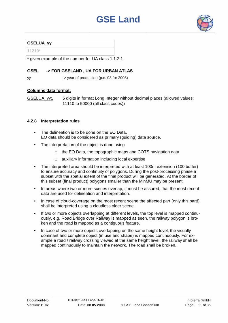
GSELUA_yy
11210*
* given example of the number for UA class 1.1.2.1
GSEL -> FOR GSELAND , UA FOR URBAN ATLAS
yy -> year of production (p.e. 08 for 2008)
Columns data format:
GSELUA_yy:, 5 digits in format Long Integer without decimal places (allowed values: 11110 to 50000 (all class codes))
4.2.8 Interpretation rules
• The delineation is to be done on the EO Data. EO data should be considered as primary (guiding) data source.
• The interpretation of the object is done using
o the EO Data, the topographic maps and COTS navigation data
o auxiliary information including local expertise
• The interpreted area should be interpreted with at least 100m extension (100 buffer) to ensure accuracy and continuity of polygons. During the post-processing phase a subset with the spatial extent of the final product will be generated. At the border of this subset (final product) polygons smaller than the MinMU may be present.
• In areas where two or more scenes overlap, it must be assured, that the most recent data are used for delineation and interpretation.
• In case of cloud-coverage on the most recent scene the affected part (only this part!) shall be interpreted using a cloudless older scene.
• If two or more objects overlapping at different levels, the top level is mapped continu-ously, e.g. Road Bridge over Railway is mapped as seen, the railway polygon is bro-ken and the road is mapped as a contiguous feature.
• In case of two or more objects overlapping on the same height level, the visually dominant and complete object (in use and shape) is mapped continuously. For ex-ample a road / railway crossing viewed at the same height level: the railway shall be mapped continuously to maintain the network. The road shall be broken.
GSE Land
Document-No. ITD-0421-GSELand-TN-01 Infoterra GmbH Version: I1.02 Date: 08.05.2008 © GSE Land Consortium Page: 12 of 36
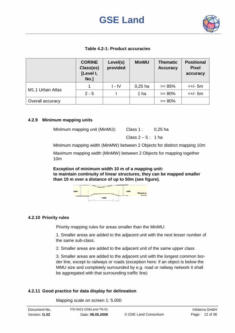
Table 4.2-1: Product accuracies
CORINE Class(es) [Level I,
No.]
Level(s) provided
MinMU Thematic Accuracy
Positional Pixel
accuracy
1 I - IV 0,25 ha >= 85% <+/- 5m M1.1 Urban Atlas
2 - 5 I 1 ha >= 80% <+/- 5m
Overall accuracy >= 80%
4.2.9 Minimum mapping units
Minimum mapping unit (MinMU): Class 1 : 0,25 ha
Class 2 – 5 : 1 ha
Minimum mapping width (MinMW) between 2 Objects for distinct mapping 10m
Maximum mapping width (MinMW) between 2 Objects for mapping together 10m
Exception of minimum width 10 m of a mapping unit: to maintain continuity of linear structures, they c an be mapped smaller than 10 m over a distance of up to 50m (see figure) .
4.2.10 Priority rules
Priority mapping rules for areas smaller than the MinMU:
1. Smaller areas are added to the adjacent unit with the next lesser number of the same sub-class.
2. Smaller areas are added to the adjacent unit of the same upper class
3. Smaller areas are added to the adjacent unit with the longest common bor-der line, except to railways or roads (exception here: if an object is below the MMU size and completely surrounded by e.g. road or railway network it shall be aggregated with that surrounding traffic line)
4.2.11 Good practice for data display for delineati on
Mapping scale on screen 1: 5.000

GSE Land
Document-No. ITD-0421-GSELand-TN-01 Infoterra GmbH Version: I1.02 Date: 08.05.2008 © GSE Land Consortium Page: 13 of 36
4.3 VISUAL EXAMPLES FOR RANDOM DISTRIBUTIONS
from CLC 2000 Mapping Guide Add.2000

GSE Land
Document-No. ITD-0421-GSELand-TN-01 Infoterra GmbH Version: I1.02 Date: 08.05.2008 © GSE Land Consortium Page: 14 of 36
4.4 LEGEND TABLE
Table 4.4-1: UA nomenclature (in bold: classes with out any further subdivision)
GSELand M1.1 Urban Atlas
UrbanAtlas No.
Vector Data Code
Nomenclature Additional Information
GSELUA_yy
1 Artificial surfaces
1.1 Urban fabric
1.1.1 11100 Continuous Urban fabric (S.L. > 80%) FTS required *
1.1.2 11200 Discontinuous urban fabric (S.L. 10% - 80%)
1.1.2.1 11210 Discontinuous Dense Urban Fabric (S.L.: 50% - 80%)
FTS required
1.1.2.2 11220 Discontinuous Medium Density Urban Fab-ric (S.L.: 30% - 50%)
FTS required
1.1.2.3 11230 Discontinuous Low Density Urban Fabric (S.L.: 10% - 30%)
FTS required
1.1.3 11300 Isolated Structures
1.2 Industrial, commercial, public, military, private and transport units
1.2.1 12100 Industrial, commercial, public, military and private units
zoning data / field check recommended
1.2.2 12200 Road and rail network and associated land COTS navigation data re-quired **
1.2.2.1 12210 Fast transit roads and associated land COTS navigation data re-quired
1.2.2.2 12220 Other roads and associated land COTS navigation data re-quired
1.2.2.3 12230 Railways and associated land COTS navigation data re-quired
1.2.3 12300 Port areas zoning data / field check recommended
1.2.4 12400 Airports zoning data / field check recommended
GSE Land
Document-No. ITD-0421-GSELand-TN-01 Infoterra GmbH Version: I1.02 Date: 08.05.2008 © GSE Land Consortium Page: 15 of 36
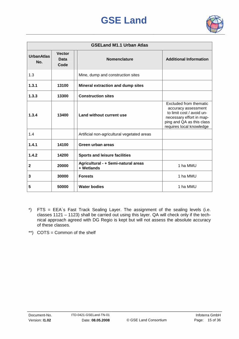
GSELand M1.1 Urban Atlas
UrbanAtlas No.
Vector Data Code
Nomenclature Additional Information
1.3 Mine, dump and construction sites
1.3.1 13100 Mineral extraction and dump sites
1.3.3 13300 Construction sites
1.3.4 13400 Land without current use
Excluded from thematic accuracy assessment to limit cost / avoid un-
necessary effort in map-ping and QA as this class requires local knowledge
1.4 Artificial non-agricultural vegetated areas
1.4.1 14100 Green urban areas
1.4.2 14200 Sports and leisure facilities
2 20000 Agricultural - + Semi-natural areas + Wetlands
1 ha MMU
3 30000 Forests 1 ha MMU
5 50000 Water bodies 1 ha MMU
*) FTS = EEA´s Fast Track Sealing Layer. The assignment of the sealing levels (i.e. classes 1121 – 1123) shall be carried out using this layer. QA will check only if the tech-nical approach agreed with DG Regio is kept but will not assess the absolute accuracy of these classes.
**) COTS = Common of the shelf

GSE Land
Document-No. ITD-0421-GSELand-TN-01 Infoterra GmbH Version: I1.02 Date: 08.05.2008 © GSE Land Consortium Page: 16 of 36
4.5 DECISION RULES
GSE Land
Document-No. ITD-0421-GSELand-TN-01 Infoterra GmbH Version: I1.02 Date: 08.05.2008 © GSE Land Consortium Page: 17 of 36
4.6 DESCRIPTION OF MAPPING UNITS URBAN ATLAS
1 Artificial Surfaces
Surfaces with dominant human influence but without agricultural land use.
These areas include all artificial structures and their associated non-sealed and vege-tated surfaces.
Artificial structures are defined as buildings, roads, all constructions of infrastruc-ture and other artificially sealed or paved areas.
Associated non-sealed and vegetated surfaces are functionally related areas to human activities, except agriculture.
Also the areas where the natural surface is replaced by extraction and / or deposition or designed landscapes ( as urban parks or leisure parks) are mapped herein this class.
The land use is dominated by permanently populated areas and/ or traffic, explora-tion, non-agricultural production, sports, recreation and leisure.
1.1 Urban fabric
Built-up areas and their associated land, such as gardens, parks, planted ar-eas and non-surfaced public areas and the infrastructure, if these areas are not suitable to be mapped separately w.r.t. MinMU size.
At least 10 % of the area should be covered by artificial structures.
Basically the classes 1.1.1 and 1.1.2.x are distinguished by their degree of soil sealing.
Residential structures and patterns are predominant, but also downtown areas and city centres, with the central business districts (CBD) and with partial resi-dential use are included.
The Urban Fabric classes (1.1.x) are distinguished only by their degree of soil sealing not by their type of buildings (single family houses or apartment blocks).
The detailed descriptions of the different classes below are given to the interpreters to support the delineation of mapping objects with homogeneous sealing density (without being required to assign the exact density classes)
Using the COTS navigation data as a skeleton for the urban area, in many cases it is necessary to subdivide the blocks formed by the COTS navigation data due to differ-ent sealing density of the residential areas or different functions of the buildings and their associated land.
After completion of the interpretation the sealing level information from the FTS seal-ing layer is integrated into the data.

GSE Land
Document-No. ITD-0421-GSELand-TN-01 Infoterra GmbH Version: I1.02 Date: 08.05.2008 © GSE Land Consortium Page: 18 of 36
1.1.1 Continuous Urban Fabric
Special Note:
Mapping the 3 rd level is done only with the defined application of the FTS Sealing layer.
MinMU 0,25 ha, Minimum width: 10 m
Land Cover:
Average degree of soil sealing: > 80%
Built-up areas and their associated land, if these areas are not suitable to be mapped separately w.r.t. MinMU size.
Buildings, roads and sealed areas cover most of the area, non-linear areas of vegetation and bare soil are exceptional.
Land Use:
Predominant residential use: areas with a high degree of soil sealing, inde-pendent of their housing scheme. (Single family houses or high rise dwellings, city centre or suburb).
Included are downtown areas and city centres, central business districts (CBD) as long there is partial residential use.
1.1.2 Discontinuous Urban Fabric
Special Note:
Mapping the 4 th level of density classes is done only with the def ined application of the FTS Sealing layer.
Land Cover:
Average degree of soil sealing: 10 - 80%
Built-up areas and their associated land (small roads, sealed areas including non-linear areas of vegetation and bare soil), if these areas are not suitable to be mapped separately w.r.t. MinMU size.
This type of land cover can be distinguished from continuous urban fabric by a larger fraction of non-sealed and / or vegetated surfaces: gardens, parks, planted areas and non-surfaced public areas.

GSE Land
Document-No. ITD-0421-GSELand-TN-01 Infoterra GmbH Version: I1.02 Date: 08.05.2008 © GSE Land Consortium Page: 19 of 36
Land Use:
Predominant residential usage. Contains more than 20 % non – sealed areas, independent their housing scheme. (Single family houses or high rise dwell-ings, city centre or suburb).
The non – sealed areas might be private gardens or common green areas.
A feature of clear urban use if located within the urban fringe can be classi-fied as 1.1.2.3., even though if the sealed surface is below 10%.
The vegetated areas might be predominant, but the land is not dedicated to forestry or agriculture.
Not included are:
Farms with large buildings (agro-industrial production), � class 1.2.1.
Nurseries with dominant areas of greenhouses (no or only small fields) � class 1.2.1.
Allotment gardens � class 1.4.2
Holiday villages (“Club Med”) � class 1.4.2
1.1.2.1 Discontinuous Dense Urban Fabric
MinMU 0,25 ha, Minimum width: 10 m
Average degree of soil sealing: >50 - 80%
Predominant residential buildings, roads and other artificially surfaced areas.
1.1.2.2 Discontinuous Medium Density Urban Fabric
MinMU 0,25 ha, Minimum width: 10 m
Average degree of soil sealing: >30 - 50%
Predominant residential buildings, roads and other artificially surfaced areas.
The vegetated areas are predominant, but the land is not dedicated to forestry or agriculture.
1.1.2.3 Discontinuous Low Density Urban Fabric
MinMU 0,25 ha, Minimum width: 10 m
Average degree of soil sealing: 10 - 30%
Predominant residential buildings, roads and other artificially surfaced areas.

GSE Land
Document-No. ITD-0421-GSELand-TN-01 Infoterra GmbH Version: I1.02 Date: 08.05.2008 © GSE Land Consortium Page: 20 of 36
A feature of clear urban use if located within the urban fringe can be classified as 1.1.2.3., even though the sealed surface is below 10%.
The vegetated areas are predominant, but the land is not dedicated to forestry or agriculture. Example: exclusive residential areas with large gardens.
1.1.3 Isolated Structures
MinMU 0,25 ha, MaxMU: 2ha , Minimum width: 10 m
Isolated artificial structures with a residential component, as such as (small) indi-vidual farm houses and related buildings.
The mapping unit will never be surrounded by any urban class other than transporta-tion network.
The mapping unit is not larger than 2 ha.
Exception: Border blocks / polygons in housing developments (they may adjacent to roads and non-urban classes).
1.2 Industrial, commercial, public, military, priva te and transport units
At least 30% of the ground is covered by artificial surfaces. More than 50% of those artificial surfaces are occupied by buildings and / or artificial structures with non-residential use, i.e. industrial, commercial or transport related uses are dominant
1.2.1 Industrial, commercial, public, military and private units
MinMU 0,25 ha, Minimum width: 10 m
Land Cover:
Artificial structures (e.g. buildings) or artificial surfaces (e.g. concrete, asphalt, tar, macadam, (tarmac) or otherwise stabilised surface, e.g. compacted soil, devoid of vegetation), occupy most of the surface.
Included are associated areas, such as roads, sealed areas, vegetated areas, if these areas are not suitable to be mapped separately w.r.t. MinMU size.
Land Use:
Industrial, commercial, public, military or private units. The administrative boundaries of the production or service unit is mapped, included associated features larger than the MinMU. (e.g. sporting areas or transport structures).
Comprised are also:

GSE Land
Document-No. ITD-0421-GSELand-TN-01 Infoterra GmbH Version: I1.02 Date: 08.05.2008 © GSE Land Consortium Page: 21 of 36
• Bare soil and/or grassland potentially used for storage of material or standing-out of livestock.
• Compounds with significant amount of green or natural areas but with industrial, commercial, military or public use. Example: Communication Tower, Antennas or wind motors and their associated land.
This class contains:
a) Industrial uses and related areas:
Sites of industrial activities, including their related areas. Production sites, energy plants: nuclear, solar, hydroelectric, thermal, electric and wind farms sewage-treatment plants farming industries. (Farms with large buildings or / and greenhouses, not fields of production) Antennas, even with predominant vegetated areas. The vegetated areas may be predominant, but the land is not dedicated to forestry or agriculture.
• Water treatment plants
• Sewage plants
• Seawater desalination plants
The industrial units can be distinguished from residential build up areas by the type of buildings, their access to transport features and the surroundings:
• Large area buildings, (inside not all rooms need day light as in dwelling houses)
• Good access to traffic ways and parking for customers
• Industrial areas are often outside the historical city centre
b) Commercial uses, retail parks and related areas
Surfaces purely occupied by commercial activities, including their related ar-eas (e.g. parking sites even larger as MinMU).
High rise office buildings;
Petrol and service stations within built-up areas.
The commercial units can be distinguished from residential build up areas by the type of large buildings, their access to transport features and the sur-roundings:
• large area buildings, (inside not all rooms need day light as in dwelling houses)
• Good access to traffic ways and parking for customers

GSE Land
Document-No. ITD-0421-GSELand-TN-01 Infoterra GmbH Version: I1.02 Date: 08.05.2008 © GSE Land Consortium Page: 22 of 36
• Pure Commercial areas are often outside the historical city centre
Not included are:
Petrol stations along fast transit and main roads with access only from this road. They are mapped together with the road transport system � class 1.2.2 1 or 1.2.2.2
c) Public, military and private services not relate d to the transport system
Surfaces purely occupied by general government, public or private administra-tions including their related areas (access ways, lawns, parking areas).
Included are:
• Schools and universities
• Hospitals and other sanitary services/buildings
• Places of worship (churches/cathedrals/religious buildings)
• Cemeteries
• Archaeological sites and museums
• Administration buildings, ministries
• Penitentiaries
• Military areas including bases and airports
• Military exercising areas fenced and under current use
• Castles etc. not primarily used for residential purposes (building man-agement, gardeners etc. living there is not residential use in this sense)
• Private storage areas without residential component as compounds of garages.
Not included are:
Public parks � class 1.4.1
Holiday resorts including their hotels � class 1.4.2
Sport Centres or bathing centres � class 1.4.2
d) Civil protection and supply infrastructure
• Dams, dikes, irrigation and drainage canals and ponds and other tech-nical public infrastructure, to be mapped including the roads, embank-ments and associated land.

GSE Land
Document-No. ITD-0421-GSELand-TN-01 Infoterra GmbH Version: I1.02 Date: 08.05.2008 © GSE Land Consortium Page: 23 of 36
• Includes also breakwaters, piers and jetties. sea walls and flood de-fences
• (Ancient) City walls, other protecting walls, bunkers
• Avalanche barriers
Not included are:
Noise barriers � class 1.2.2.x
Water courses (within e.g. diked canals) if water area is wider than 10m � class 5
Reservoirs along natural water courses � class 5
1.2.2 Road and Rail network and associated land
Special Note:
The road and railway network (COTS navigation data) is ingested into the classifica-tion database according to the method given in the Annex.
Parts of the COTS navigation data that are obviously not congruent with the corre-sponding traffic line in the EO data and topomap need to be corrected
Roads which are not contained in the COTS navigation data are mapped by the Ser-vice provider according the mapping criterias defined herein this mapping guide.
Roads or Railroads does not necessarily have to form a closed network. Isolated traf-fic lines are possible, but they are to be mapped w.r.t. MinMU criterium.
Associated land is mapped towards the roads/railways as it is visible in the EO data and topographic maps.
Associated lands are:
• Slopes of embankments or cuts
• Enclosed areas by roads, railways without direct access and without ag-ricultural land use
• Fenced areas along roads (protection against wild animals)
• Areas enclosed by motorways, exits or service roads with no detectable access
• Noise barriers (fences, walls, earth walls)
• Rest areas, service stations and parkings only accessible from the fast transit roads
• Railroad facilities including stations, cargo stations and service areas.
• Foot- bicycle paths parallel to the traffic line
• Green strips, alleys (with trees or bushes)

GSE Land
Document-No. ITD-0421-GSELand-TN-01 Infoterra GmbH Version: I1.02 Date: 08.05.2008 © GSE Land Consortium Page: 24 of 36
1.2.2.1 Fast transit roads and associated land
MinMU 0,25 ha, Minimum width: 10 m
Motorways with COTS navigation data attribute “Motorways” and motorway rest and service areas and parkings, only accessible from the motor-ways.
Motorways that are not included in the COTS navigation data are to be mapped by the Service provider.
1.2.2.2 Other roads and associated land
MinMU 0,25 ha, Minimum width: 10 m
Roads, crossings, intersections and parking, including roundabouts, sealed areas with “road surface”
1.2.2.3 Railways and associated land
MinMU 0,25 ha, Minimum width: 10 m
Railroad facilities including stations, cargo stations and service areas.
1.2.3 Port areas
MinMU 0,25 ha, Minimum width: 10 m
Special Note:
Ancillary data is recommended to identify the administrative boundary of the port area. The delineation itself is to be done on the EO data:
• Detailed city / tourist maps or
• Field check (On site visit) or
• Local zoning data
Administrative area of inland harbours, sea ports. Infrastructure of port areas, includ-ing quays, dockyards, transport and storage areas and associated areas.
Not included are:
Marinas � class 1.4.2.

GSE Land
Document-No. ITD-0421-GSELand-TN-01 Infoterra GmbH Version: I1.02 Date: 08.05.2008 © GSE Land Consortium Page: 25 of 36
1.2.4 Airports
MinMU 0,25 ha, Minimum width: 10 m
Special Note:
Ancillary data is recommended to identify the administrative boundary of the port area. The delineation itself is to be done on the EO data:
• Detailed city / tourist maps or
• Field check (On site visit) or
• Local zoning data
Administrative area of airports, mostly fenced.
Included all airport installations: runways, buildings and associated land.
Not included are:
Aerodromes without sealed runway � class 1.4.2.
1.3 Mine, dump and construction sites
1.3.1 Mineral extraction and Dump sites
MinMU 0,25 ha, Minimum width: 10 m
Special Note:
Ancillary data is recommended to identify the administrative boundary. The delinea-tion itself is to be done on the EO data:
• Detailed city / tourist maps or
• Field check (On site visit) or
• Local zoning data
Included are: open pit extraction (sand, quarries) incl. water surface, if < MinMU, open-cast mines, inland salinas, oil and gas fields
Included are: their protecting dikes and / or vegetation belts and associated land as e.g. service areas, storage depots.
Included are: public, industrial or mine dump sites, raw or liquid wastes, legal or ille-gal, their protecting dikes and / or vegetation belts and associated land as e.g. ser-vice areas.

GSE Land
Document-No. ITD-0421-GSELand-TN-01 Infoterra GmbH Version: I1.02 Date: 08.05.2008 © GSE Land Consortium Page: 26 of 36
Not included are:
Water bodies > MinMU � class 5
Exploited peat bogs � class 2
Coastal salinas � class 2
Re-cultivated areas (mapped according their actual land cover) � class 2 or 3
River bed extraction � class 2
Decanting basins of biological water treatment plants � class 1.2.1.
1.3.3 Construction sites
MinMU 0,25 ha, Minimum width: 10 m
Spaces under construction or development, soil or bedrock excavations for construc-tion purposes or other earthworks visible in the image.
Clear evidences of actual construction need to be identifiable in the data, such as ac-tual excavations and machinery on site, or ongoing construction of any stage etc.
In case of doubt: � class 1.3.4
1.3.4 Land without current use
MinMU 0,25 ha, Minimum width: 10 m
Areas in the vicinity of artificial surfaces still waiting for being used or re-used. The area obviously in a transitional position, “waiting for being used”.
Waste land, removed former industry areas, (“brown fields”) gaps in between new construction areas or left over land in the urban context (“green fields”)..
No actual agricultural or recreational use.
No construction is visible, without maintenance, but no undisturbed fully natural or semi-natural vegetation, (secondary ruderal vegetation)
Also areas where street network is already finished, but actual erection of buildings still not visible
Not included are:
“Left over areas”, areas too small / narrow for any construction w.r.t. MinMU size. � map to the appropriate neighbour class as associated land

GSE Land
Document-No. ITD-0421-GSELand-TN-01 Infoterra GmbH Version: I1.02 Date: 08.05.2008 © GSE Land Consortium Page: 27 of 36
1.4 Artificial non-agricultural vegetated areas
Vegetation planted and regularly worked by man, strongly human influenced.
Sporting facilities as functional units independent of being not sealed, sealed or build up.
1.4.1 Green urban areas
MinMU 0,25 ha, Minimum width: 10 m
Public green areas, predominant recreational use as gardens, zoos, parks, castle parks,
Suburban natural areas that have become and are managed as urban parks.
Forests or green areas extending from the surrounding into urban areas are mapped as green urban areas when at least two sides are bordered by urban areas and struc-tures and traces of recreational use are visible.
Not included are:
Private gardens within housing areas � class 1.1
Cemeteries � class 1.2.1
Buildings within parks as castles or museum � class 1.2.1
Patches of natural vegetation or agricultural areas being enclosed by built up areas without being managed as green urban area � class 1.x
1.4.2 Sports and leisure facilities
MinMU 0,25 ha, Minimum width: 10 m
All sports and leisure facilities including associated land, independent if public or commercially managed: e.g. Theresienwiese (Munich), Public arenas for any kind of sports incl. associated green areas, parking places etc.:
• Golf courses
• Sports fields (also outside the settlement area)
• Camp grounds
• Leisure parks
• Riding grounds
• Racecourses
• Amusement parks
• Swimming resorts etc.
• Holiday villages (“Club Med”)

GSE Land
Document-No. ITD-0421-GSELand-TN-01 Infoterra GmbH Version: I1.02 Date: 08.05.2008 © GSE Land Consortium Page: 28 of 36
• Allotment gardens1.
• Glider or sporting airports, aerodromes without sealed runway.
• Marinas
Not included are:
Private gardens within housing areas � class 1.1
motor racing courses within industrial zone used for test purposes � class 1.2 1
caravan parking used for commercial activities � class 1.2.1
Soccer fields etc. within e.g. military bases or within university campus � class 1.2.1
2 Agricultural + Semi-natural + Wetland areas MinMU 1 ha
a) Arable land:
• Fields under rotation system. Can be non-irrigated or permanently irri-gated. Includes also rice field.
• Fields laid in fallow are included.
b) Permanent crops:
• Fruit orchards, scattered fruit trees with pasture,
• Vineyards and their nurseries,
• Roses
• Olive groves
• Berries and hop plantations
c) Pasture & natural grassland:
• Grassland
• Pasture and meadow under agricultural use, grazed or mechanically harvested.
1 Allotment gardens are complexes of few up to hundreds of land parcels assigned to residential peo-ple. Most of the parcels contain individual cultivation areas with fruits, mainly vegetables as well as a shed for tools and shelter.
GSE Land
Document-No. ITD-0421-GSELand-TN-01 Infoterra GmbH Version: I1.02 Date: 08.05.2008 © GSE Land Consortium Page: 29 of 36
d) Shrubs and / or herbaceous Vegetation incl. tran sitional woodland
• Vegetation cover more than 50%, ground coverage of trees with height > 5 m: < 30%, areas with minor / without artificial or agricultural influ-ence.
• Sclerophyllous vegetation
• bushy Sclerophyllous vegetation (e.g. maquis, garrigue)
• Abandoned arable land with bushes
• Woodland degradation: storm, snow, insects or air pollution
• Forest regeneration / re-colonisation: Clear cuts, new forest plantations,
• Areas under power transmission lines inside forest;
• Fire breaks
• Steep bushy slopes of eroded areas;
• Abandoned vineyards or orchards, arable land and pasture land under natural colonisation.
• Dehesas with bush proliferation indicating no agricultural or farming use for a rather long time.
• Bushy areas along creeks;
e) Moors and Heathland:
• Bushes, shrubs and herbaceous plants, dwarf forest in alpine or coastal regions (Pinus Mugo forests) Height is maximum 3 m in climax stage.
f) Beaches, dunes, sands:
• < 10% vegetation cover
• Beaches, dunes and sand plains, (coastal or inland location), gravels along rivers.
• Seasonal rivers, if water is characteristic in shorter part of the year (< 2 months).
g) Bare rocks:
• > 90% of the land surface bare rocks, (i.e. < 10% vegetation)
• Rocks, gravel fields, landslides Scree, (fragments resulting from mechanical & chemical erosion. Wea-thering rocks forming heaps of coarse debris at the foot of steep slopes), cliffs, rocks

GSE Land
Document-No. ITD-0421-GSELand-TN-01 Infoterra GmbH Version: I1.02 Date: 08.05.2008 © GSE Land Consortium Page: 30 of 36
h) Sparsely vegetated areas:
• Steppes, tundra, badlands, scattered high altitude vegetation. Bare soils inside military training areas. Vegetation cover 10 - 50%
i) Burnt areas:
• Recently burnt forest or shrubs (but not natural grassland), still mainly black on EO data
j) Snow and ice
• Glacier and perpetual snow.
k) Inland wetlands:
• areas flooded or liable to flooding during a great part of the year by fresh, brackish or standing water with specific vegetation coverage made of low shrub, semi-ligneous or herbaceous species;
• Water fringe vegetation, reed beds of lakes, rivers and brooks. Sedge and fen-sedge beds, swamps;
• Peat bogs, with or without peat extracting areas
• Shallow water areas covered with reed
• Seasonal rivers, if water course is not visible in the EO Data
l) Coastal wetlands:
• areas, flooded or liable to flooding during the great part of the year by brackish or saline water, susceptible to flooding by sea water. Often in the process of filling in and gradually being colonized by halophytic plants.
• Specific vegetation coverage made of low shrub, semi-ligneous or her-baceous species.
• Alluvial planes, marshes and intertidal flats.
• Salinas (salt production sites by evaporation)
not included are:
Military exercising areas fenced and under current use � class 1.2.1
Greenhouses � class 1.2.1
Inland salinas � class 1.3 1

GSE Land
Document-No. ITD-0421-GSELand-TN-01 Infoterra GmbH Version: I1.02 Date: 08.05.2008 © GSE Land Consortium Page: 31 of 36
3. Forest (natural and plantation) MinMU 1 ha
• With grounds coverage of tree canopy > 30%, tree height > 5 m, includ-ing bushes and shrubs at the fringe of the forest.
• Included are plantations as Populus plantations, Christmas tree planta-tions.
not included are:
Forest within urban areas and human pressure respectively � class 1.4.1
5. Water
MinMU 1 ha
The visible water surface area on the EO Data is delineated. EO data should be considered as primary (guiding) data source.
• Sea
• Lakes
• Fish ponds (natural, artificial)
• Rivers, incl. channelled rivers
• Canals Default source for delineation is the EO data. If no clear delineation is possible using EO data the other reference datasets may be used for that. Examples are:
• Reservoirs
• Water courses or ponds with strongly variable surface level
All of water bodies and water courses visible in the imagery are mapped as long as they exceed an extent of 1 ha.
Water courses are mapped continuously also when water surface is covered by vegetation. If the water is partly obscured e.g. by vegetation the delineation shall be oriented at other parts of the water where it is not obscured.
Included are: seasonal rivers, if the water course is visible in the EO Data, otherwise � class 2.
Fish ponds with distance < 10 m are mapped together.
COTS navigation data water layer may be used as reference for interpretation. How-ever, delineation of water areas must be done using the EO data, as the geometric of accuracy of COTS navigation data water object is too coarse for mapping in scale 1:10.000.

GSE Land
Document-No. ITD-0421-GSELand-TN-01 Infoterra GmbH Version: I1.02 Date: 08.05.2008 © GSE Land Consortium Page: 32 of 36
Not included are:
Shallow water areas covered with reed > MinMU � class 2
Seasonal rivers, if water course is not visible in the EO Data � class 2

GSE Land
Document-No. ITD-0421-GSELand-TN-01 Infoterra GmbH Version: I1.02 Date: 08.05.2008 © GSE Land Consortium Page: 33 of 36
5. ANNEX
5.1 PRE-PROCESSING AND GEOMETRIC ADAPTATION OF COTS NAVIGATION DATA
The COTS navigation data by default comes with a certain categorisation of its street network. Two basic categories are important within the context of the Urban Atlas. The first category gives informa-tion about the Functional Road Class (FRC) of each road, the second one gives information about the importance of each road within the city traffic network (Net2Class)
The COTS navigation data currently used shows the following categories for FRC and Net2Class:
FRC Full name
0 Motorway, Freeway or other Major Road
1 Major Road less important than a Motorway
2 Other Major Road
3 Secondary Road
4 Local Connecting Road
5 Local Road of high importance
6 Local Road
7 Local Road of minor importance
8 Other Road
Net2Class Importance Level
0 First class (Highest)
1 Second class
2 Third class
3 Fourth class
4 Fifth class
5 Sixth class
6 Seventh class (Lowest)
Usage of COTS navigation data for the Urban Atlas:
The COTS navigation data will be used to generate the street and railroad network of the mapping product. This network will serve as a “backbone” and is decisive for the look & feel of the final product.
The data is delivered in line vector format by the data provider. These lines need to be widened so that the traffic line network of the final product covers the transport areas in the EO data.

GSE Land
Document-No. ITD-0421-GSELand-TN-01 Infoterra GmbH Version: I1.02 Date: 08.05.2008 © GSE Land Consortium Page: 34 of 36
For that purpose a usage and buffering strategy was developed to implement the COTS navigation data into the product.
The integration of the traffic network shall be done in advance to all other visual or (semi) automatic delineation and labelling of objects.
The goal of the traffic line implementation process is to ingest a traffic line network into the mapping product that covers all traffic lines wider than 10m (including their associated land – see traffic line de-scription: chapter 6, class 1.2.2) and – on the other hand – being cost-efficient to integrate.
To achieve that goal the following strategy was developed:
• The railway network is delineated individually if it exceeds a minimum width of 10m incl. its as-sociated land.
• The most important roads (FRC classes 0, 1) will be delineated individually.
• The majority of the roads (FRC classes 2 to 5) will be ingested by buffering the line vectors. The buffered roads will have an overall width of at least 10m. The buffering width for each FRC class will be adapted to the local conditions of each individual city to resemble the overall characteristics of the local traffic network.
• Certain roads (FRC class 6) will be mapped (by buffering) or left out according to the decision of the service provider. This is to preserve a common look & feel of the mapping products of different cities.
• The other roads (FRC classes 7, 8) are not foreseen to be ingested into the mapping product. The default width of these roads or paths does not exceed the minimum width of 10 meters.
• The importance of each road is resembled by the attribute “Net2Class”. This importance level is also considered during the buffering of the road network
The following table gives an overview on the treatment of the COTS road network:
Net2Class
FRC 1 2 3 4
0 Manual
1 Manual
2 Estimated buffer
width
Estimated buffer
width
Estimated buffer
width
Estimated buffer
width
3 Estimated buffer
width
Estimated buffer
width
Estimated buffer
width
Estimated buffer
width
4 Estimated buffer
width
Estimated buffer
width
Estimated buffer
width
Estimated buffer
width
5 Estimated buffer
width
Estimated buffer
width
Estimated buffer
width
Estimated buffer
width
6 Mapping decided on city basis
7 Not mapped

GSE Land
Document-No. ITD-0421-GSELand-TN-01 Infoterra GmbH Version: I1.02 Date: 08.05.2008 © GSE Land Consortium Page: 35 of 36
The general procedure for the road buffering is as follows:
PRE-PROCESSING
• Identification of the different combinations for fields NET2CLASS and FRC.
• Decision whether to include FRC=6 or not based on visual inspection.
• Sampling of a number of streets (up to service provider) for each combination.
• Estimation of mean width for each combination.
• Recommended is the use of VHR imagery (e.g. GoogleEarth). If city not available at VHR, a city with similar morphology in the same country may be used along with the EO data for pro-duction).
PROCESSING
• Buffering implementation
• Manual delineation of streets FRC=0 and 1
POST-PROCESSING
• Manual delineation of streets wider than 10m that have not been buffered previously (i.e. not present in the street network layer or belonging to combinations not considered for buffering).
• Correction (elimination/edition) of errors due to inaccuracies of the line street network or buff-ering process.
Post-processing will be implemented according to SP’s production chain

GSE Land
Document-No. ITD-0421-GSELand-TN-01 Infoterra GmbH Version: I1.02 Date: 08.05.2008 © GSE Land Consortium Page: 36 of 36
Figure 1: Example for the expected “Look & Feel” of the final Urban Atlas product from City of Bremen.
Note: To enhance general visibility the following modifications towards default nomenclature were made: Streets are in dark colours (classes 122x0)