Mapping Greece’s
72
i Mapping Greece’s Network Infrastructure Student Name: Xenakis Konstantinos SID: 3301130018 SCHOOL OF SCIENCE & TECHNOLOGY A thesis submitted for the degree of Master of Science (MSc) in Information and Communication Systems NOVEMBER 2014 THESSALONIKI – GREECE
Transcript of Mapping Greece’s

i
Mapping Greece’s
Network Infrastructure
Student Name: Xenakis Konstantinos
SID: 3301130018
SCHOOL OF SCIENCE & TECHNOLOGY
A thesis submitted for the degree of
Master of Science (MSc) in Information and Communication Systems
NOVEMBER 2014
THESSALONIKI – GREECE

ii
Mapping Greece’s
Network Infrastructure
Student Name: Xenakis Konstantinos
SID: 330110018
Supervisor: Prof. Nick Savage
Supervising Committee Mem-
bers:
Assoc. Prof. Name Surname
Assist. Prof. Name Surname
SCHOOL OF SCIENCE & TECHNOLOGY
A thesis submitted for the degree of
Master of Science (MSc) in Information and Communication Systems
NOVEMBER 2014
THESSALONIKI – GREECE

iii
Abstract
This dissertation was written as a part of the MSc in ICT Systems at the International
Hellenic University.
This dissertation tries and succeeds to map Greece’s ISP Network Infrastructure
with the use of a script that executes numerous traceroutes to Greek IP ranges. The
script was hosted in a Linux-Based server located in International Hellenic University’s
Infrastructure and was scheduled to run every three minutes for a period of three weeks.
During this period the script executed 17376 traceroutes and managed to discover 38
different ISPs both Greek and European and 983 routers in total. Also discovered rout-
ers and their connections are visualized as shown in chapter 5. For the visualization of
the collected data, Gephi Software and Google Maps were used. Through the visualiza-
tion and the collected data, it becomes easier for the reader to understand how Greece’s
Internet Topology is designed, the role Greece plays to the World Wide Web and the
Redundancy of Greece’s Network Infrastructure.
Finally, I would like to express my deepest gratitude to my supervisor, Dr Nick
Savage for his excellent guidance, patience and for helping me to deepen into the do-
main of ISPs topologies.
Last, I would like to thank my mother. She was always supporting me and en-
couraging me with her best wishes.
This dissertation is dedicated to the memory of my beloved father Col. Georgios K
Xenakis.
Thank you for everything.
Konstantinos G. Xenakis
22/11/14
iv
Contents
Abstract ........................................................................................................................................ iii
1. Introduction ........................................................................................................................... - 1 -
2. Background-Literature Review ............................................................................................. - 7 -
2.1 Internet Topology ............................................................................................................ - 7 -
2.1.1 Inter-Domain Topology ............................................................................................ - 8 -
2.1.2 Point of Presence (POP Level) ................................................................................. - 8 -
2.1.3 Router level topology ............................................................................................... - 9 -
2.1.4 Internet Routing Policies ........................................................................................ - 11 -
2.2 BGP (Border Gateway Protocol) ................................................................................... - 11 -
2.3 EGP (Exterior Gateway Protocol) ................................................................................. - 13 -
3. Related Work ....................................................................................................................... - 15 -
3.1 Routeviews Archive ...................................................................................................... - 15 -
3.2 Traceroute ...................................................................................................................... - 16 -
3.2.1 How traceroute works ............................................................................................ - 16 -
3.3 Related Traceroute based studies .................................................................................. - 18 -
3.4 Rocketfuel ..................................................................................................................... - 18 -
3.4.1 Path Reductions ...................................................................................................... - 19 -
3.4.2 Ingress Reduction ................................................................................................... - 20 -
3.4.3 Egress Reduction .................................................................................................... - 20 -
3.4.4 Next Hop AS Reduction ......................................................................................... - 20 -
3.4.5 Alias Resolution ..................................................................................................... - 21 -
3.5 AROMA ........................................................................................................................ - 22 -
3.5.1 Selection of Targeted IP Addresses ........................................................................ - 22 -
3.5.2 Probing Servers Selection ...................................................................................... - 24 -
3.5.3 Probing ................................................................................................................... - 24 -
3.5.4 AROMA’s Alias Resolution .................................................................................. - 25 -
3.6 Summary ....................................................................................................................... - 26 -
4. Methodology ....................................................................................................................... - 27 -
4.1 Traceroute ...................................................................................................................... - 27 -

v
4.1.1 Script ...................................................................................................................... - 28 -
4.2 Processing the data ........................................................................................................ - 29 -
4.3 Server ............................................................................................................................ - 30 -
4.4 Gephi ............................................................................................................................. - 31 -
4.4.1 Importing data ........................................................................................................ - 31 -
4.4 Autonomous Systems .................................................................................................... - 33 -
4.5 Geo Layout .................................................................................................................... - 34 -
4.6 Adding Map .................................................................................................................. - 36 -
4.7 Grouping ....................................................................................................................... - 38 -
5. Findings ............................................................................................................................... - 41 -
5.1 Internet Exchange Service ............................................................................................. - 41 -
5.2 Routers in numbers ....................................................................................................... - 43 -
5.3 Connectivity .................................................................................................................. - 44 -
5.4 Backbone Topologies .................................................................................................... - 45 -
5.5 POP findings ................................................................................................................. - 47 -
5.5.1 Summary ................................................................................................................ - 49 -
5.6 Router Findings ............................................................................................................. - 50 -
5.7 Redundancy ................................................................................................................... - 50 -
5.7.1 OTE SA Network ................................................................................................... - 50 -
5.7.2 GRNET Network Topology ................................................................................... - 52 -
5.7.3 Summary ................................................................................................................ - 54 -
5.8 Traffic Crossroad .......................................................................................................... - 55 -
6. Conclusions and future works ............................................................................................. - 57 -
6.1 Conclusions ................................................................................................................... - 57 -
6.1.1 Gathering of data .................................................................................................... - 57 -
6.1.2 Processing the data ................................................................................................. - 57 -
6.1.3 Visualization of data .............................................................................................. - 58 -
6.2 Future work ................................................................................................................... - 58 -
Bibliography............................................................................................................................ - 59 -
APPENDIX ............................................................................................................................. - 61 -
Script ................................................................................................................................... - 62 -


- 1 -
1. Introduction
Τhe Internet started as an experimental project for the purpose of serving the needs of
the United States Army. Through the years the Internet has evolved from a small classi-
fied technology called ARPANET [1] with few hosts and routers to an enormous net-
work with million nodes and links that users around the world use, providing services
such as voice, video, browsing with great speeds that no one could imagine at the be-
ginning.
Although the Internet is used by millions of people on a daily basis very few ef-
forts have been made to map the Internet Network infrastructure of the world. Also, this
dissertation is the first effort for mapping Greece’s ISP1 network topology since no one
has ever tried before.
Through the understanding of the Network infrastructure we can improve the
network management capabilities and implement new network simulators. By building
new network simulators, we can understand the vulnerabilities of networks and propose
new methods to counter any future problems. The reason behind this is that it is much
easier to test the Internet in a simulated environment rather than test it directly in real
time. Building an efficient model is a complex task since accurate data are needed; such
data can be obtained by mapping the Internet network so the more accurate the data the
better simulation model will be built.
The purpose of this dissertation is to Map Greece’s Internet Network Infrastruc-
ture with the use of different tools which are explained in the chapters that follows.
Since Greece is considered new to the Internet, till now no previous attempt has
been made by other researchers to map Greece’s Network Infrastructure. Only little in-
formation is available about Greece’s network topology, since the Internet Service Pro-
viders except the GRNET [2] prefer not to publish such information.
1 ISP: Internet Service Provider.

- 2 -
The network topology of ISPs influences in a great degree the dynamics of rout-
ing protocols, the scalability and of course its resilience. Also by having a clear picture
about a network topology gives you the ability to act fast and counter any failures and
future problems that will show up in the future.
Mapping Greece’s network has many advantages and can be very useful for re-
searchers and students to understand how the “Internet” works and especially in Greece.
Also by mapping the Greek network will give us the ability to see if and how Greece is
acting as an intermediate node for Internet communication among other countries and
how Greece is connected to other countries and especially to Europe.
Another problem that this dissertation is trying to solve is to see how different
Autonomous Systems (AS) are connected and interact with one another. Different ASes
are connected through routers that run the Border Gateway Protocol (BGP) and act as
border routers, Routers that are located inside the AS are called backbone routers.
Traceroute2 is a very powerful tool for network troubleshooting and provides
much information about how packets travel through the network. Therefore, I chose to
use Traceroute to map Greece’s network. In order to map such large networks require
numerous traceroutes to different ISPs, of course this solution unless it is automated can
become very time consuming and demands a lot of resources.
Like all previous attempts, I decided to use the traceroute command to gain in-
formation about the ISP routers, of course it was not so simple since thousands of trac-
eroutes should be produced to gain an accurate ISP network map, based on the trac-
eroute command I divided the whole effort into three steps. Although the ideas behind
these steps were simple I had to make many back steps and rethink every step more than
once.
The first step was to create a script that would produce numerous traceroutes to
numerous IP addresses. For obvious reasons producing the traceroutes manually would
require enormous time and effort thus I chose to write a script that would randomly pro-
duce IP addresses and traceroutes to the whole spectrum of IP ranges all around the
world, of course private IP addresses had to be excluded. The script should be light-
weight, fast and require few processing and network resources, therefore I chose to
2 Traceroute: Computer Network Diagnostic tool.

- 3 -
write the script in bash script, this was an easy effort with few lines of code. Next It was
decided to choose a server that would run this script and store the output data into a .txt
file. The first thought was to run the script into a Linux desktop computer housed local-
ly in my house, but this idea was rejected almost immediately since this would require
my PC running 24 hours a day and seven days a week, also this implementation would
put my ISP into suspicion since it might be thought that I was producing these trac-
eroutes for malicious reasons.
The choice that I made was to lease an Amazon server 3 located in the United
States, although this choice seemed good at the beginning it proved wrong since it pro-
duced many unnecessary data with little useful information about Greece’s Network. To
be more specific, only about two per cent of the total traceroutes contained information
about Greek ISPs. Therefore, it was decided to rewrite the script in order to be focused
only on Greek IP addresses. Although this idea proved correct the traceroutes still pro-
duced many unnecessary data since the source of traceroutes was located on the East
Coast of United States and traveled through Europe in order to reach their final destina-
tion, filing the traceroute output with many unnecessary hops.
For the above reason it was decided to transfer my script into a Greek Linux
based server. In this effort I got help from the IT department of the International Hel-
lenic University (IHU) where they offered me access into a Linux based Server housed
in the University’s Campus4. During this step a lot of time was consumed and I had to
speed up the process, therefore I rescheduled the cronjob5 run by the server from five to
three minutes. The Cronjob produced 20 traceroutes per hour, but again this proved not
the best solution since as it will be described in chapter six it would be best to use sim-
ultaneously different Servers, located in different places in Greece and would not be-
long to the GRNET ISP. GRNET is an ISP that connects the Greek Universities and
Schools to the Internet. Also, it was discovered later that all the traffic was served from
the city of Athens. In other words, although the International Hellenic University is lo-
cated in the city of Thessaloniki almost all its traffic has to be served from a router lo-
cated in the city of Athens.
3Amazon Web Services. http://aws.amazon.com/
4IHU Campus Location http://www.ihu.edu.gr/index.php/contact.html
5is a time-based job scheduler in Unix-like computer operating systems

- 4 -
The next step was to decide which of the data that were gathered were useful
and which had to be ruled out. The choice that was made was to use only the hops that
contained information about the hostnames of the routers that the traceroutes were go-
ing through. After excluding these traceroutes a linked list had to be made for every
traceroute in order every traceroute to be stored in one line of the .txt file. Also dupli-
cate traceroutes were excluded since duplicates would not be in use. Also only few trac-
eroutes reached their final destination. But this was not a problem since I wanted to map
the ISP routers and the client routers would be useless in my dissertation.
The third step was to find a way to visualize the data in a way that the output
could be easily be understood by the readers in order to have a clear image about how
backbone routers are connected to one another and how different Autonomous Systems
interact among them. There were many thoughts about this step, but since the time was
limited I decided to use Gephi6 which is an open source software with many tools and
capabilities.
First the txt file that contains the traceroute output was converted into a .csv file,
also the headers “source” and “target” had to be added, in this way Gephi would be in
the position to create edge lists visualizing all the links and nodes creating a graph, but
this was not enough since although the connection would be clear I would not able to
understand the boundaries of each AS and also where every node is located. Therefore
more columns were added that contained information about the AS, location and the
ISP of every node. After that, using a tool on Gephi I was able to create a graph with the
routers relocated based on their coordinates.
Since all the routers did not contain information about their location some of
them had to be excluded, of course, only the routers that were acting as end points into
the map where excluded while for some others their location had to be presumed based
on the location of their neighbors. For instance, if a router was between two routers that
were both located in Athens it was presumed that the router itself was located in Athens
also.
This process gave a much clearer image of the links and nodes, but it still
doesn’t help the user since unless he is familiar with the locations of the cities of Greece
6 http://gephi.github.io/

- 5 -
he will not be able to understand fully where the ISP routers are housed and which cities
are connected to one another. So it was decided to add in the background an image with
the map of Europe. This thought, despite the fact that was correct the user would not be
able to interact with the routers and the map itself. Therefore, it was decided to import
the graph that it was created in Google Maps since Google offers this service to users.
The final output is presented clearly in chapter five.


- 7 -
2. Background-Literature Review
In this chapter, I am going to present and analyze the basic components of the Internet
Topology and the Routing Protocols that it uses. Also, I am going to refer into meas-
urement methods that previous researchers used for mapping ISP router Topologies.
Readers should already be familiar with network terminologies.
2.1 Internet Topology
Network topology is consisted of graphs and nodes. The internet is consisted of several
different types of topologies; these topologies can be organized by level of granularity.
In this section, I am going to describe three levels of network topology. These levels are
the Inter-domain, Point of Presence Level (POP), and the Router Level Topology.
Figure 1 shows an inter-domain topology. Largest ISPs in tier-1 are connected to a group,
Smaller tier-1 ISPs connect to some of tier-1 ISPs and they might be connected to each other.
- 8 -
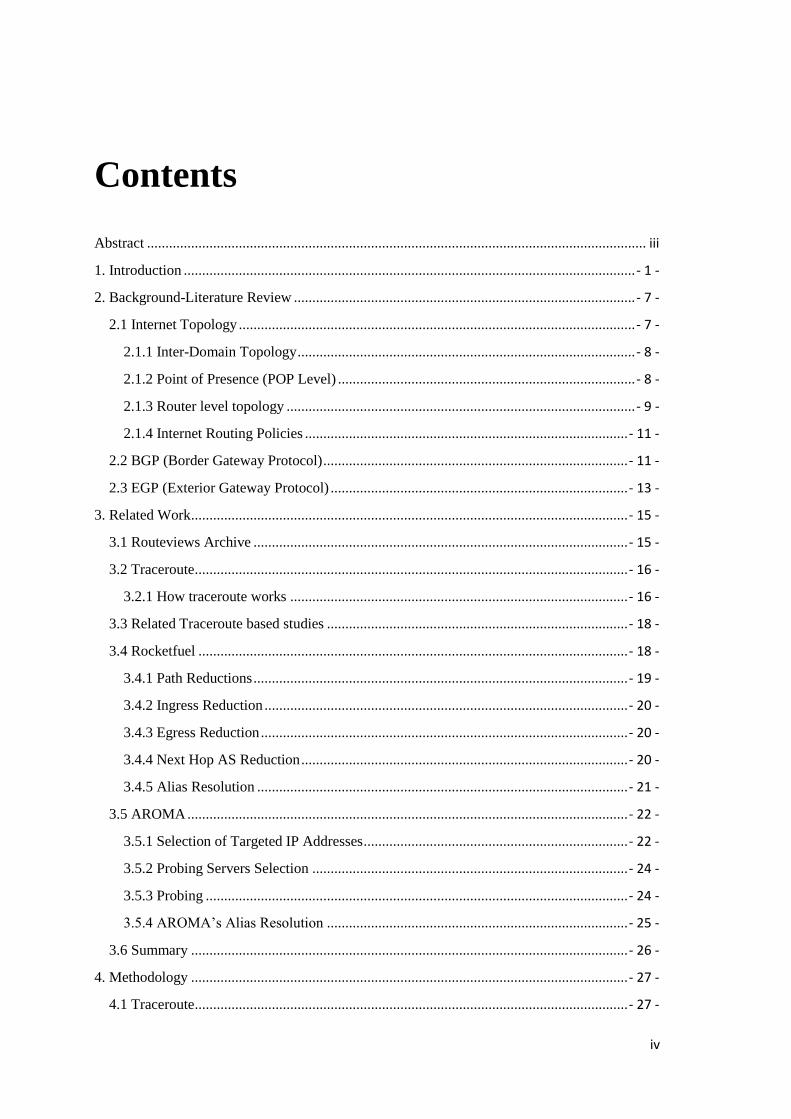
The clouds in the bottom represent customer ASs. Large customers may be connected directly
to tier-1 group.
2.1.1 Inter-Domain Topology
Figure 1 represents an inter-domain topology. Each Autonomous System is represented
by a cloud in the figure. The ASes provide services to others are called Internet Service
Providers. Each edge among the clouds represents a business relationship that is respon-
sible for the exchange of traffic among the ASes.
The Internet may be divided into different sub-networks that are connected to
each other. Each sub-network is handled by different administrative authorities, in most
cases these authorities are the Internet Service Providers. Each sub-network is called
domain or Autonomous System. At this level, every AS is represented in a graph by a
node and the connection to other ASes as links. Of course not all ASes act the same.
There are some ASes that act as cores in the Inter Domain Topology.
2.1.2 Point of Presence (POP Level)
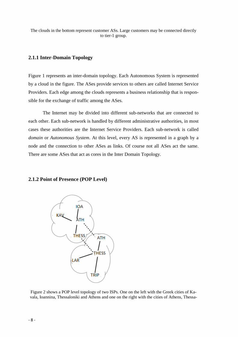
Figure 2 shows a POP level topology of two ISPs. One on the left with the Greek cities of Ka-
vala, Ioannina, Thessaloniki and Athens and one on the right with the cities of Athens, Thessa-

- 9 -
loniki, Larisa and Tripoli. Solid lines represent POP connections within an ISP while dotted
lines represent peering links between POPs in different ISPs.
POP level topology is the same as inter-domain topology with added geographical loca-
tion information. Each Internet Service Provider houses collections of Routers in differ-
ent geographical locations; a Point Of Presence consists of a summary of routers that
are housed in the same building by an ISP in a specific geographical location. There are
cases and Greece is such, where different ISPs house their routers in the same building;
these buildings are called exchange points or co-location facilities. This happens for
many reasons and one of them might be that in some cases Greek ISP shares the same
medium to connect their POPs together. A POP is illustrated in Figure 2. The edges be-
tween POPs represent backbone links within the ISPs or peering links to other ISPs. By
understanding the way that POP level topology is designed and works, we can under-
stand the routes that connect different geographical locations.
2.1.3 Router level topology
In the router level topology, every node is router and links represent IP-level connectivi-
ty among different routers. Routers have processors and use operating systems also in
order to allow connectivity to other routers have many network interfaces. Router’s
main task is to forward packets. In plain words, routers are constructed and programmed
to receive packets from one interface and forward them through another. Routers that
consumers use in everyday life are smaller versions of the routers that ISPs use, with the
difference that they have different types of interfaces, both wired and wireless. Every
interface is assigned to an IP address and according to the receivers IP address routers,
decide from which interface to forward the packet.

- 10 -
Figure 3 shows a small office network topology. The box represents a router with three interfac-
es. The bottom interface is a wireless interface, the top in the connection to the Internet and the
left is used for desktop computers. The table on the left illustrates the routing table.
In order to describe how IP addresses are allocated to the interfaces I use a small
example as shown in Figure 3. The box in the middle represents a router with three in-
terfaces, the upper interface is for connection to the Internet, the lower is used for wire-
less connection and the left is for providing connection to the office’s desktop comput-
ers. The table on the right illustrates the routing table that is stored inside the router. I
am not going to describe what the subnet prefixes in the IP addresses represent since I
except that readers are familiar with this terminology.
Every router maintains a routing table where in this example has five entries.
Routing tables provide information to routers on how to handle the outgoing packets.
For instance, let’s suppose that the router receives a packet with the field of destination
address equal to 1.2.3.15, the router will read its routing table and then it will decide to
forward the packet to the left interface. In another case when a packet is received with a
destination IP address that is not included in the routing table, then the router is config-
ured to forward this packet to the upper interface. There are numerous ways and meth-
ods that a router creates its routing table depending on the routing protocol that it uses.
For example routing tables can be inserted manually into the router and there are other
more intelligent routing protocols where routers form and create neighbor relationships

- 11 -
on their own and their routing table is automatically created by the updates that they re-
ceive from their neighbors.
Networks run by the ISPs are like the network illustrated in Figure 3 only that it
differs in many ways. First routers that ISPs use have many more interfaces, but the
subnets are much smaller. Second the routing tables are configured by the routing pro-
tocol, unlike the network in Figure 3 which is small enough and can be configured
manually.
Every router has a role to play in the topology. Routers that are used to connect
to other POPs are called backbone routers. The links between backbone routers are usu-
ally high-capacity links and are few in number. The routers that are used to aggregate
many low-capacity connections are called access routers, also known as gateway rout-
ers.
2.1.4 Internet Routing Policies
Each router is configured to use a Routing Protocol. Routing protocols deter-
mine how routers communicate with each other by processing multiple information that
assists them to determine which route to follow. These decisions are made by the rout-
ing algorithms. Also, routers exchange information about the state of network and any
possible link failures. The policies of the ISP dictate through configuration of the router
which routes to follow based on different information. Such a routing protocol is Border
Gateway Protocol (BGP) [3] which I am about to explain in the next section.
2.2 BGP (Border Gateway Protocol)
In this section, the Border Gateway Protocol [3] is described. The main purpose of BGP
protocol Systems is to exchange network reachability information to other BGP Sys-
tems.

- 12 -
BGP is an inter-Domain routing Protocol, which ISPs run in order to choose the
best paths inside the inter-domain topology. The Border Gateway Protocol is a Distance
Vector protocol. Distance Vector Protocols, advertise routes as vectors of (distance, di-
rection), in other words Distance Vector Protocols use hops to count the distance and
which router is the next hop in order to determine the direction. Since each router relies
on the information that he receives from his neighbor routers we sometimes refer to
these protocols as “routing by rumor”.
BGP is considered a simple protocol, but is has some important features [4]. Af-
ter two neighbors have established connection, communicate and exchange their full
routing tables, they exchange only updates about changes to the routing tables that they
previously exchanged. Second routes are advertised at the prefix level, third the BGP
update messages may contain numerous fields, including a list of prefixes being adver-
tised, withdrawn a list of attributes with various characteristics.
ISPs have several alternative routes to a destination. In case that no routing poli-
cy was used, the Routers will choose the shortest path to reach a destination, but in or-
der the ISP to have more control on the route selection, many additional attributes are
added during the updates allowing routers to change their routing decisions based on
these updates. The final result is shown in Table 1.
Table 1 shows router’s decision table

- 13 -
The above table shows the decision process of the router. The router reads the list and
compares its attribute in the list across two routers. In case where the routers have dif-
ferent values the router chooses the one with the most desirable attribute.
2.3 EGP (Exterior Gateway Protocol)
In this section, I am going to describe the Exterior Gateway Protocol [5]. “The purpose
of the Exterior Gateway Protocol (EGP) is to enable one or more autonomous sys-
tems to be used as transport media for traffic originating in some other autonomous sys-
tem and destined for yet another, while allowing the end-user to see the composite of
all the autonomous systems as a single internet, with a flat, uniform address space.”
[5]
Regardless of the fact that EGP is considered as a dynamic routing protocol, it
uses a very simple mechanism and design, since it doesn’t use metrics or other functions
in order to determine the best route. EGP routers send updates which contain network
reachability information which specify the networks that are reachable through certain
routers.
EGP runs three simple main functions. First routers speaking EGP establish their
neighbors. Neighbors are EGP speaking routers that share reachability information.
Second EGP routers survey their neighbors in order to determine whether they are up
and running. And last EGP routers constantly exchange update messages that containing
information about the reachability of networks within their ASes.
As previously mentioned, we can see the simplicity of the EGP routing protocol
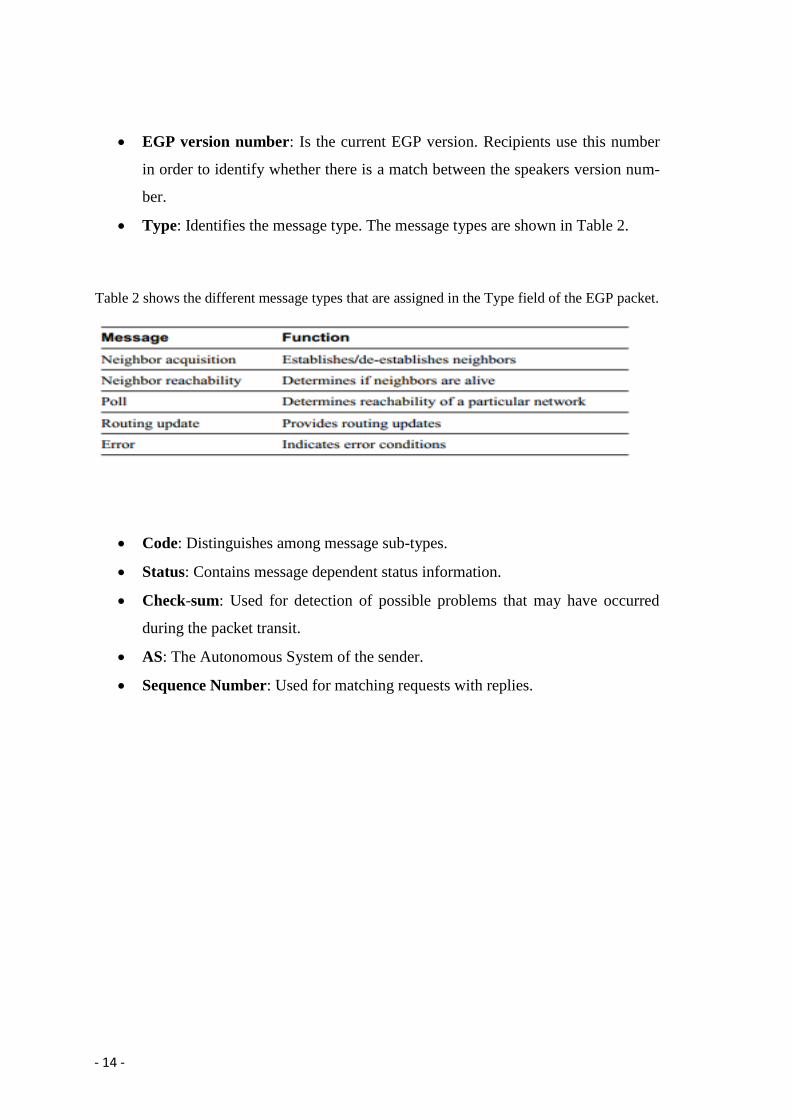
just by looking at the structure of the EGP packets. Figure 4 shows an EGP packet.
Figure 4 shows the architecture of an EGP packet.
- 14 -
EGP version number: Is the current EGP version. Recipients use this number
in order to identify whether there is a match between the speakers version num-
ber.
Type: Identifies the message type. The message types are shown in Table 2.
Table 2 shows the different message types that are assigned in the Type field of the EGP packet.
Code: Distinguishes among message sub-types.
Status: Contains message dependent status information.
Check-sum: Used for detection of possible problems that may have occurred
during the packet transit.
AS: The Autonomous System of the sender.
Sequence Number: Used for matching requests with replies.

- 15 -
3. Related Work
In this chapter I am going to describe the main information sources that I use in this dis-
sertation. Such information is traceroute measurements, host-Linux command, Routing
tables, and router address names. Also, I am going to describe previous efforts for map-
ping ISP routing topologies.
3.1 Routeviews Archive
In this section follows a small description of RouteViews project [6].
Routeviews is a project that collects and stores BGP Routing tables from multi-
ple ISPs. The project was launched from the University of Oregon in the year 1999. In
order to receive update information they set BGP routers to connect with other BGP
routers located all around the world.
The University of Oregon through Routeviews continuously publishes updates.
Archives of GBP updates from 53 Internet Service Providers. Since not all ISPs ex-
change info with the University’s BGP routers we can say that the information about
inter-domain is partial.
The BGP routing protocol, is a path vector routing protocol thus in every adver-
tisement routers exchange a list of Autonomous Systems used to reach a destination, by
collecting and combining multiple paths from multiple IP prefixes from ISPs the
RouteViews archive is created. This process is based on the BGP routing tables.
When to BGP neighbors establish connection they become peers or neighbors as
we commonly refer to them. After they become neighbors both of them start to ex-
change their routing tables. In this is how Routeviews archive is created.
As a result, BGP information is provided directly to end-hosts that participate in
network measurement. Such example, are the nodes in PlanetLab [7], [8].

- 16 -
3.2 Traceroute
In this section the history and functionality of traceroute command are described.
Traceroute is a simple but powerful computer network diagnostic tool that net-
work administrators use in order to obtain information about a network state and deter-
mine if any failures occur. It was first written by Van Jacobson in 1988 at the Lawrence
Berkeley National Laboratory [9]. In this section I will make a brief description on how
traceroute works for mapping Network Topologies and present previous related efforts.
3.2.1 How traceroute works
All IP packets that travel through the Internet have a field called TTL; TTL stands for
Time To Live. Time to Live is measured by the maximum number of hops that a packet
can travel across the Internet, before it is discarded. The default value that traceroute
command uses is 30.
Every time that a packet is forwarded by a Router the TTL is increased, when it
reaches 30 which is the default maximum value, the receiving router will drop the
packet, before doing this the router will inform the sender that the TTL value was ex-
ceeded.
The Internet policy dictates that when you send something to a receiver, the re-
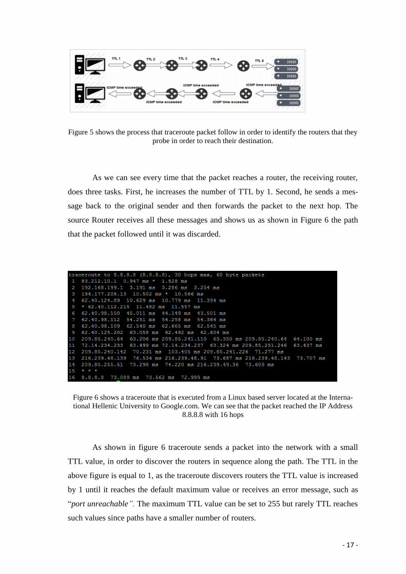
ceiver will be in a position to know the address of the sender. Figure 5 illustrates this
function.
- 17 -
Figure 5 shows the process that traceroute packet follow in order to identify the routers that they
probe in order to reach their destination.
As we can see every time that the packet reaches a router, the receiving router,
does three tasks. First, he increases the number of TTL by 1. Second, he sends a mes-
sage back to the original sender and then forwards the packet to the next hop. The
source Router receives all these messages and shows us as shown in Figure 6 the path
that the packet followed until it was discarded.
Figure 6 shows a traceroute that is executed from a Linux based server located at the Interna-
tional Hellenic University to Google.com. We can see that the packet reached the IP Address
8.8.8.8 with 16 hops
As shown in figure 6 traceroute sends a packet into the network with a small
TTL value, in order to discover the routers in sequence along the path. The TTL in the
above figure is equal to 1, as the traceroute discovers routers the TTL value is increased
by 1 until it reaches the default maximum value or receives an error message, such as
“port unreachable”. The maximum TTL value can be set to 255 but rarely TTL reaches
such values since paths have a smaller number of routers.

- 18 -
Traceroute is a fundamental network tool that administrators use in order to test
the ISP routing policies and discover any potential problems or faults. Unfortunately
traceroute is only capable to discover the outgoing path and cannot discover the incom-
ing path. This drawback of traceroute created the need for public traceroute servers.
Public traceroute servers are web servers that execute traceroutes to any given IP
address. Nowadays, numerous traceroute servers exist located around the world.
3.3 Related Traceroute based studies
In this section, previous related Internet mapping approaches are described. Τhe works
of Sangmin Kim and Khaled Harfoush (AROMA) [10] and Spring, Mahajan, Wetherall,
Anderson (Rocketfuel) [11] are illustrated and contrasted .
Prior internet mapping efforts relied on the choice of their traceroute destina-
tions, such as their choice of IP or router level mapping. Also some of them developed
techniques for efficient network mapping and alias resolution.
Most of the mapping projects chose to use a small number of destinations. They
based on the idea that they should traceroute to as many as possible responsive destina-
tions, since unresponsive destinations would be useless and cause overhead to their da-
ta.
3.4 Rocketfuel
Spring, Mahajan, Wetherall and Anderson on Rocketfuel [11] in order to reduce the re-
quired number of measurements decided to use two classes of techniques. These tech-
niques are called Directed Probing and Path Reduction.
Since real topologies of ISPs are not public, Rocketfuel wanted to discover the
router level connectivity and POP structure with as much as minimum effort. Rocket-
fuel researchers decided that for selecting measurements, they needed intelligent trac-

- 19 -
eroutes that were expected to transit the ISPs, also when two or more traceroutes enter
and leave the ISP at the same point, they measured only one of them since the duplicate
traceroutes would not offer more useful information. For this reason they decided to use
Directed Probing and Path Reductions. Also by this method they managed to map 40-
80% of the routers in the United States by using only 0.1% of the traced required by a
brute force mapping.
Directed Probing is used for identifying traceroutes that will transit the ISP
Network. Since BGP routing tables are not available, they decided to use RouteViews
[6] for their effort since it provides BGP views from 60 different points around the In-
ternet. With directed probing the traceroutes will travel through the ISP in three cases.
First, if the traces are sent to a destination within the ISP. Second in case the traceroute
server is in the ISP and third traceroutes that are likely to transit the ISP based on same
AS-path are called up/down traces.
3.4.1 Path Reductions
Not all the traceroutes that were chosen by directed probing were expected to take
unique paths in the ISP. In order to reduce more the measurements, they decided to ex-
clude the traceroutes that were expected to have an identical path inside the ISP. They
created a list with three techniques. Ingress Reduction, Egress Reduction, Next Hop AS
Reduction.
(a) (b) (c)

- 20 -
Figure 7 : Path reductions find traceroutes likely to traverse the same path through an ISP. (a)
Ingress Reduction: Only one traceroute needs to be taken per destination when two vantage
points (T’s) share an ingress. (b) Egress Reduction: Only one traceroute needs to be taken when
two dependent prefixes (P’s) share an egress router. (c) Next-hop AS Reduction: Only one trac-
eroute needs to be taken if two prefixes are reached through the same next-hop AS.
3.4.2 Ingress Reduction
There are cases where if traceroutes from two different traceroute servers to the same
destination enter the ISP at the same point, it is very likely that the path through the ISP
to be the same. As illustrated in figure 7 (a) the traceroute from T2 to the destination
could be redundant with the traceroute from T1, of course it is easily understood that
only one of them is needed. The idea is that when a traceroute enters frequently the ISP
from one router and treaceroutes from other servers enter at the same point, then the
traceroute path that will be discovered will be equivalent.
3.4.3 Egress Reduction
On the contrary, when two destination prefixes are reached using the same egress router
(point) they are considered equivalent. This is illustrated in figure 7 (b).
3.4.4 Next Hop AS Reduction
When prefixes are reached outside the ISP the path usually depends on the next hop AS.
In figure 7 (c) are illustrated the prefixes that are reached using the same next-hop AS.
The idea is the same like Egress Reduction but next-hop Reduction finds prefixes that
share a next-hop AS.
The difference between Egress Reduction and next-hop AS is discrete since in
one case the exit point for a dependent prefix is an egress router while for the other is
another Autonomous System and identified by next-hop AS.

- 21 -
These three methods are used in order to predict the point where traceroutes will
enter and exit the ISP. When a path has already been discovered, these mechanisms will
skip this traceroute and Rocketfuel will select another.
3.4.5 Alias Resolution
The first technique for Alias Resolution as previously mentioned was introduced by
Pansion and Grand and was in the Mercator Project [12]. Alias resolution detects aliases
by sending a traceroute probe directly to an IP address using high UDP port number and
TTL equal to 255. In this way routers are expected to send the message “UDP port un-
reachable” including a field with the outgoing IP address as the source IP address. In
this way two aliases will respond using the same IP address. In Rocketfuel they used
another method in order to identify any aliases which is called, IP Identifier.
The IP identifier is used in the reassembly packet process. It is commonly im-
plemented by a counter that increases its value when a packet is generated. This implies
that when packets are sent in a row it expected that will have consecutively IP Identifi-
ers.
Figure 8 shows Alias resolution using IP identifiers. A solid arrow represents messages to and
from one IP address, a dotted arrow messages to the other.
As shown in figure 8 ally sends a probe packet to the two potential aliases. The
port unreachable responses, including the IP IDs x and y. Ally then sends a third packet

- 22 -
to one of the potential aliases and receives IP ID equal to z. In case that x<y<z and are
consecutive these addresses are potential aliases. Rocketfuel also used a fourth packet in
order the results to be more accurate.
3.5 AROMA
Sangmin Kim and Khaled Harfoush of the North Carolina State University tried to cre-
ate more detailed Internet IP maps using fewer resources than previous methods like
Rocketfuel. They named their project AROMA [10] which is an Internet Router Level
Mapping tool that tries to identify all interfaces from every router inside a targeted Au-
tonomous System.
In the next section I am going to present the methodology that AROMA [10] is
using in order to penetrate deeper inside an Autonomous Systems and reveal as many
routers as possible using fewer resources.
3.5.1 Selection of Targeted IP Addresses
Since Address space information is public through many registry services like ARIN
[13], APNIC [14] and RIPE [15] AROMA uses these resources in order to fed its
mechanism as shown in Figure 9.

- 23 -
Figure 9 shows the steps of the AROMA mechanism.
As shown in figure 9 AROMA process constitutes of 5 steps. Firstly AROMA is
fed with the IP address space corresponding to a targeted AS from registry services like
[13] [14] [15]. The choice of IP address doesn’t occur randomly since this could lead to
unnecessary results.
AROMA tries and succeeds in most cases to select IP addresses that correspond
to real routers by excluding unused IP addresses and end points of the network. This
process happens with the use of Domain Name System [16] since typically network
administrators assign meaningful names to the routers for managerial reasons.
By selecting only the IP addresses that have assigned names referring to the AS
the unused IP addresses and those that belong to customers are excluded. There are
some cases thaw that customers of an AS have assigned hostnames to their IP addresses,
in these cases those IP addresses were included. Table 3 illustrates the numbers of IP
addresses corresponding to the four ISPs (Sprintlik, Level3, Verio, Abovenet) with as-
signed names and those that were chosen to be probed.

- 24 -
Table 3 shows the number of IP addresses corresponding to five US ISPs
We can clearly see in table 3 that the number of targeted IP addresses is significantly
smaller the IP addresses with assigned names.
3.5.2 Probing Servers Selection
AROMA has access to almost 280 probing servers that are located all around the world
in the PlanetLab Facility [7]. Although they have access to such an enormous number of
traceroute servers only a few was decided to be used in every probe of a targeted AS.
The idea behind this is that only a fraction of servers is able to discover a path inside the
AS since if traceroute probes to the same destination enter at the same ingress point it is
almost certain that they will follow the same path in order to reach their destination.
AROMA randomly picks a small number of IP addresses that belong to the tar-
geted AS and probes them through all 280 probe servers. Then the servers that enter the
AS from different ingress points are selected for probing.
3.5.3 Probing
In this step, every IP address in the list becomes a destination for traceroutes from mul-
tiple probing servers. This process has a drawback since the possibility of overwhelm-
ing a single router is very possible. In order to workaround this problem they decided to
randomize the order in which the IP addresses are probed and also probing traffic was
rate-limited.
By comparing the interface’s IP address against the pool of IP addresses of tar-
geted AS obtained by [14] [13] [15], they succeeded to identify whether an IP address
- 25 -
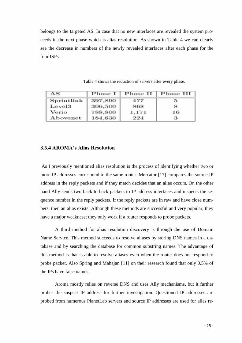
belongs to the targeted AS. In case that no new interfaces are revealed the system pro-
ceeds in the next phase which is alias resolution. As shown in Table 4 we can clearly
see the decrease in numbers of the newly revealed interfaces after each phase for the
four ISPs.
Table 4 shows the reduction of servers after every phase.
3.5.4 AROMA’s Alias Resolution
As I previously mentioned alias resolution is the process of identifying whether two or
more IP addresses correspond to the same router. Mercator [17] compares the source IP
address in the reply packets and if they match decides that an alias occurs. On the other
hand Ally sends two back to back packets to IP address interfaces and inspects the se-
quence number in the reply packets. If the reply packets are in raw and have close num-
bers, then an alias exists. Although these methods are successful and very popular, they
have a major weakness; they only work if a router responds to probe packets.
A third method for alias resolution discovery is through the use of Domain
Name Service. This method succeeds to resolve aliases by storing DNS names in a da-
tabase and by searching the database for common substring names. The advantage of
this method is that is able to resolve aliases even when the router does not respond to
probe packet. Also Spring and Mahajan [11] on their research found that only 0.5% of
the IPs have false names.
Aroma mostly relies on reverse DNS and uses Ally mechanisms, but it further
probes the suspect IP address for further investigation. Questioned IP addresses are
probed from numerous PlanetLab servers and source IP addresses are used for alias re-

- 26 -
solving. In this way more accuracy is succeeded since aliases might be revealed from
other vantage points.
Table 5 compares the findings from Rocket with AROMA.
We can clearly see the difference between the two methods as shown in Table 5.
The most significant difference is shown in the third row of the table where AROMA
managed to discover almost 75000 Verio Routers while Rocketfuel only 6.523. In order
to be fair, it worth saying that AROMA focused only on four ISP routers while Rocket-
fuel on ten.
3.6 Summary
The methods that were presented in this chapter were designed to map selected
ISP maps of the United States. Both of the methods used public traceroute serv-
ers in order to probe targeted IP address. The approach that was used for the pur-
poses of this dissertation is described in the next chapter. The main idea was to
create a script that would randomly produce IP addresses in order to be tracerout-
ed from a Linux-based server located in Greece. In other words I tried to map the
ISP network topology from the inside out.

- 27 -
4. Methodology
In this chapter, I am going to present and analyze the methodology that was used in or-
der to Map Greece’s ISP Network Topology. In order to measure router level ISP topol-
ogies efficiently, I developed several techniques that can easily be used by anyone on
the Internet.
As previous researchers did, I used different methods in this dissertation in order
to map Greece’s ISP Network infrastructure. These methods include, traceroute, reverse
DNS resolve and Gephi software which is graph visualization software.
This chapter is organized into three parts. The first part refers to how I was able
to efficiently traceroute in order to map ISP networks. The second part refers to how I
used router hostnames in order to retrieve geographical information about a router and
the third part describes by effort to visualize my findings.
4.1 Traceroute
All work that previous researchers did so far was using the traceroute command in order
to penetrate inside an ISP’s network infrastructure and discover the routes that are used
in order a packet to reach its destination.
Previous researchers like [11] [10] used public traceroute servers fed with IP ad-
dresses for their data collection. For the purposes of this dissertation, a different ap-
proach was chosen to be used. The reason behind this is that Greece is a small country
with few Internet Service Providers and with a relatively small number of routers and
links. Also Greece is connected to the rest of the world with only a couple of links as it
will later present in the next chapter.
As it was mentioned instead of using public traceroute servers it was decided to
use a Linux Based server located in Greece that automatically produces traceroutes eve-

- 28 -
ry few minutes to IP address from specific IP ranges that belong to Greek ISPs. In order
to achieve this, a script that would automatically do the above had to be created.
4.1.1 Script
First, it had to be decided which programming language had to be used in order to write
the script, there were many thoughts at the beginning but finally it was decided to write
a simple bash script. Although the idea was relatively simple many modifications had to
be made in the original script that was written since the results did not provide the need-
ed information for this dissertation.
The original script that was created, randomly produced an IP address, stored it
in a value and then a traceroute was executed to the produced IP address. The script was
executed almost for three weeks but the collected data were not sufficient since only a
very small percentage of all the probes were targeting Greek IP addresses. Since Greece
is a small country with small population it was expected that the IP addresses that Greek
ISPs hold will be also very small. In a period of three weeks with 288 traceroutes per
day, only five Greek IP addresses in total were randomly produced. For this reason, I
had to rewrite my script in order to produce only IP addresses that Greek ISPs own.
In order to discover the Greek IP ranges I used the Regional Internet Registries
Statistics database [18]. From this database a .txt file was created that stores all the
Greek IP ranges. From this .txt file the script randomly chooses an IP range that will
become the targeted IP range.
In order to produce random traceroutes the script randomly picks a line from the
.txt file and splits it into five pieces. Every piece is assigned into a variable. For exam-
ple, if the IP range 185.16.164.0/22 is selected the script reads the line, isolates every
part of the IP range and then assigns it into a variable. In this case, $sub=22, $ip4=0,
$ip3=164, $ip2=16 and $ip1=185. Then the script reads the $sub variable and after
running some “if conditions” produces the minimum and the maximum IP address in
order to choose randomly an IP address. In this case, the minimum IP address is
185.16.164.1 and the maximum is 185.16.167.254. IP address 185.16.164.0 can’t be
selected since is considered as the network.

- 29 -
Figure 10 shows a traceroute performed from the International Hellenic University to IP address
185.16.166.216. The asterisk indicates that the router that forwarded the packet didn’t return
any information.
The randomly generated IP address is stored in a variable and then a traceroute
is executed to the specific IP address. The results are stored in a .txt file for further pro-
cessing.
4.2 Processing the data
As shown in figure 10 we can see that the result from the traceroute contains much in-
formation that not all of them are useful, such information is the hop number and the
time that the packet needs in order to reach its destination.
For the above reason it was decided to remove all the unnecessary information
and keep only the IP address of every hop, another thing I decided to do was to repre-
sent every traceroute into one line in order to make something like a linked list with IP
addresses. In order to achieve this I used a simple “awk” command in Linux: awk -
F'[()]' '/^ / {printf "%s ", $2; next} /^[^[:space:]]/{print ""}' logfilev2.txt > finalv2.txt.
Another issue was the duplicate traceroutes that were produced. Duplicates were
produced in random and not by tracerouting the same IP address twice or more. In most

- 30 -
cases this occurred from the fact that some traceroutes were not probed after a specific
router. The reason behind this was that some IP addresses were not in use or they might
be protected from actions like traceroute. In order to delete all the duplicate traceroutes I
again used a simple command and significantly reduced their number. Totally 17376
traceroute were produced and after the duplicate deletion only 2836 were left. After this
the data were more clean and easier to handle.
4.3 Server
In this section are described and analyzed the reasons that lead me to choose a Linux
Based Server housed In International Hellenic University’s Infrastructure.
Previous researchers in order to produce their results, used public traceroute
servers located all around the world, but since Greece is a small county it was decided
to use only one server that would produce traceroutes every 5 minutes. Again, this
number was not randomly selected since there was a probability the server to be seen as
malicious.
Firstly, it was chosen to be used an Amazon Linux Based server that was located
on the East Coast of the United States. This proved to be a wrong choice since it pro-
duced a lot of unnecessary data. Imagine a packet travelling from the United States how
many hops it should pass through in order to reach the target IP address located in
Greece. For his reason I decided to shut down this server and relocate it into Greece.
The IT department of the International Hellenic University 7 provided me a
Linux based server in order to upload my script. International Hellenic University is lo-
cated in Thermi a city near Thessaloniki and like all Greek Universities belongs to the
AS5408 which is the GR-NET autonomous system.
Although that IHU is located in Thessaloniki, is directly connected to the web
through the GRNET that is located in Athens. For this reason all the traffic is firstly
probed to Athens and then to its final destination, so it is like the server is located in
7 http://www.itc.ihu.edu.gr/

- 31 -
Athens since there is no other connection from Athens to IHU for the specific link. So
although the first three hops are the same for all the traceroutes, number of hops de-
creased significantly, making the process of the data even easier to handle. In order to
access the Linux based server, putty8 was used and for file browsing I use WinSCP
9.
4.4 Gephi
In this section I am going to present the software that I used to visualize the data pro-
duced from the traceroutes.
The visualization of the data was the most difficult and the most interesting part
of my dissertation, since all the data that were collected should be visualized in a way
that would be presentable and easy to understand.
There were many thoughts on which software should be used to visualize the
collected data. The first thought was to use the Neo4j visualization software, 10
but un-
fortunately I had to give up on this idea since there were many compatibility issues that
had to be solved. Finally, it was decided to use Gephi which is open source visualization
software with many add-ons and capabilities.
Gephi takes as input .csv files and creates nodes and links, also has the capabil-
ity of multiple visualization and grouping methods that were very useful for the purpos-
es of this dissertation.
4.4.1 Importing data
As I previously mentioned in order to input my data into Gephi I had to convert my .txt
file into a .csv file. This process was simple since there are many ways to do this. The
8 http://www.putty.org/
9 http://winscp.net/eng/download.php
10 http://neo4j.com/

- 32 -
method that I chose was by using the Microsoft excel software11
. After converting the
file and imported it, for every IP address/Router unique node and the links that connects
them were created. The result is shown in Figure 11.
Figure 11 shows the graph created by Gephi using Yihan Fu proportional method. Different
colors represent different Autonomous Systems.
As I previously mentioned Gephi has many options about Layouts. Firstly, I
made the choice to use Yihan Fu proportional Layout since it presents my topology in a
way more meaningful. Figure 11 shows the produced results, in which every router ap-
pears as a node and also the links that connect them. Different colors as mentioned be-
fore represent different Autonomous Systems.
Although the graph provided useful connectivity information it did not provide
me any information about the nodes except its IP address. For this reason I had to find a
way to obtain extra information such as the host name, the location and the Autonomous
Systems that it belongs. For this reason it was decided to export all the IP addresses into
a txt file and run for every line the Linux hostname command. In this way every IP ad-
dress in the txt file would be replaced by the Hostname of the router that belongs. Of
course not all IP addresses correspond to a hostname. For this reason routers that didn’t
offer hostname information were left with the hostname column blank.
11
http://office.microsoft.com/en-gb/excel/

- 33 -
After obtaining the hostname of every IP address I created another column into
Gephi where I imported all the hostnames as shown in Figure 12.
Figure 12 shows how the column “hostname” appears in a small portion of our network nodes.
4.4 Autonomous Systems
In this section I am going to present how I managed to extract information about every
router’s Autonomous System.
As I mentioned in the previous chapters, by reading the hostname of a router, we
can get much useful information about its owner, AS, city and the purpose that this
router serves.
For example, the router with the hostname “athe7609b-athe-crsb-
1.backbone.otenet.net” is a backbone, Cisco 7609 router [19], located in Athens belong-
ing to OTE S.A. Also, knowing that OTE S.A belongs to the Autonomous System
AS6799 we can assume that also this router belongs to the AS6799.

- 34 -
In this step I created two extra columns, one for the autonomous system that the
router belongs and one for the city that the router is located. As in the previous step I
left blank all the routers that did not share information about their location I did not do
the same for their AS since through the RIRS database [18] we know in which AS every
IP address range belongs. There were some cases that I had to presume the location of a
router by looking into its neighbor’s location. For instance, if one router connects two
routers that are both located in Thessaloniki I can presume that this router is also located
in Thessaloniki. Figure13 shows the data after the city and the location columns are cre-
ated. As we can see there are some cases that the city column is left blank. These entries
had to be excluded as I will explain later.
Figure 13 shows the datasheet from Gephi including the two added columns that provide infor-
mation about the Autonomous System and the City that the router is located.
4.5 Geo Layout
In this section I am going to describe how I managed to add coordinates into Gephi in
order to create a clearer and easier to understand map.

- 35 -
Although I had much information about every node and its connections to other
nodes the graph did not provide clear information about the location of every node.
Luckily Gephi provides the option to import coordinates of every node. I again exported
all my data to a .csv in order to be easier to modify.
After exported all my data I imported them into Microsoft excel for further pro-
cess. I created two extra columns, one for the latitude and one for the longitude in order
to assign the coordinates of every node. Finding the coordinates the location of every
node was easy since I already have the City where they are located. Also, there are
many sites online where you input the name of the City or the building and the site out-
puts the coordinates. I decided to use worldatlas, 12
but there also many other reliable
sites to use.
After importing all the data I was able to choose the GeoLayout 13
option in
Gephi in order to make a graph based on the coordinates that I imported. The resulting
graph is shown in Figure 14. This option after inserting the coordinates of every node
relocates the nodes based on their geographical location.
Figure 14 shows all the nodes with assigned coordinates. Different colors represent the different
ASs. Nodes on the bottom of the picture have no assigned coordinates.
Of course, as I mentioned not all geographical information of the nodes were
available and many fields had to be left blank. Gephi gathers all these nodes at the bot-
tom of the graph as it appears in Figure 14.
12
http://www.iplocationfinder.com/worldatlas.com 13
https://marketplace.gephi.org/plugin/geolayout/

- 36 -
4.6 Adding Map
In this step I am going to explain how I managed to add a map on the background of my
Graph since as shown in the figure above the readers might not be able to understand
fully the topology of the Greek ISP Network unless they are fully aware of Greece’s
geography.
There were many thoughts at the beginning on how I would be able to import a
map on my graph. The first thought was to add an image of the map of Europe in the
background, but this idea was rejected early since the map would not be interactive and
would not provide any information about the nodes and the links.
After a lot of thinking I decided to use GoogleMaps14
since it has many capabili-
ties and offers many features. The problems that I faced at the beginning was how I
would be able to export my graph into a file that would be compatible with Google
Maps and how I would treat the nodes that had the coordinate fields blank. For the sec-
ond problem I decided to leave out all the nodes that have blank fields since these nodes
didn’t provide any useful information for the purposes of this dissertation. After using a
filter on Gephi I managed to exclude all the blank nodes. Now the only problem that I
needed to solve was the compatibility issue of the exported file.
Again for this step Gephi offers an addon “ExportToEarth”15
which is a free ad-
don that allows the users to export their Graph into a .kmz file which is compatible with
Google Earth. After exporting the file I managed very easily to import it into Google
Earth created the result shown in Figure 15.
14
https://www.google.gr/maps 15
https://marketplace.gephi.org/plugin/exporttoearth/

- 37 -
Figure 15 shows how the final map looks on Google Earth. Routers appear as nodes, including
their hostnames. The colors differ depending the AS that belongs
Another useful feature on Google Maps is that by clicking on a node a label
pops up, showing all the nodes that located in the same city. Also, we can get much in-
formation by clicking on a link that connects two nodes. These two features are shown
in Figures 16 and 17.
Figure 16 shows the information of the selected router.

- 38 -
Figure 17 shows which routers the link connects, in this case the connection is between two
routers that one is located in Athens and the other in Ampelokipous Thessaloniki. The picture is
from Google maps and shows the area near Macedonia Airport.
4.7 Grouping
In this section I am going to describe the reason that I chose to exclude the nodes that
had null values into the coordinate’s fields.
Since I wanted to overlay my findings on top of Google Maps, I needed to ex-
clude all the nodes that did not provide me information about their geographical loca-
tion. As I previously mentioned in case that these nodes where located between two
known locations I assumed that their location would be the same, but in case that these
nodes where end-nodes I decided to exclude them since I wanted to create an ISP Rout-
er Topology. Also, there were some cases that the end-nodes provided information
about their geographical location. Such cases were businesses that used static IP ad-

- 39 -
dresses for administrative reasons. In Figure 18 we can see the graph that was created
after I excluded the nodes with null values.
Figure 18 shows the only the nodes that provided geographical information. Different colors
represent different ASes.
Another grouping method that I used was to assign different colors for every
Autonomous System. In this way it will be easier for the readers to understand in which
AS every node belongs and how different ASes connect to each other. This was
achieved through the partitioning method that Gephi Software offers. In this way, it will
be easier for the readers to understand how different Internet Service Providers connect
to each other. Figure 19 illustrates on the left the different partitions with their colors
according the AS that every node belongs. Also, I want to specify that the colors are
changeable.

- 40 -
Figure 19 shows the different colors assigned to every node, depending on the Autonomous
System that belongs
.

- 41 -
5. Findings
In this chapter I am going to present and analyze the different findings and the conclu-
sions that I made while I was processing my collected data. I divided this chapter in
eight sections based on the different findings and conclusions that I made.
5.1 Internet Exchange Service
In this section, I am going to analyze the Internet Exchange Service of Greece. Also, I
am going to present how different ISPs use it in order to connect and communicate with
each other.
One thing that I expected to discover while I was collecting my data was how
different Internet Service Providers connect to each other. Since different ISPs belong to
different AS’es it would be difficult for them to connect with each other without having
someone to do this for them.
GR-IX was founded in 2009 and is the successor of AIX (Athens Internet Ex-
change. GR-IX is managed by the Greek Research & Technology Network (GRNET).
The main task of GR-IX is to handle the exchange of IP traffic between different ISP’s.
In Figure 20 we can see how different Autonomous Systems connect to the GR-IX. GR-
IX uses the Exterior Gateway Protocol [20].

- 42 -
Figure 20 shows GR-IX where different ISPs connect to each other. The map is from Google-
Maps.
It is obvious that if internet exchange services did not exist, the communication
between ISPs and different Autonomous Systems would be very difficult. For example,
let’s consider a traceroute that is executed from IHU to a router that belongs to the
AS6799. In this case, the packet would be served from the GR-IX [20] in order to enter
the AS6799. Figure 21 illustrates such an example.
Figure 21 shows a connection example. Clouds represent different Autonomous Systems, circles
routers and lines the links between them. Circle (a) is a GRNET router (b) the forthnet.gr-ix.gr,
(c): otenet-2.gr-ix.gr and d: is athe7609a-athe-crsb-1.backbone.otenet.net.

- 43 -
In this dissertation almost all traceroutes had to be probed through the GR-IX
since all were originated from a server that belongs to the GR-NET Internet Service
Provider.
5.2 Routers in numbers
In this section, I am going to present the number of routers that I managed to discover
during my data collection, for all Greek Internet Service Providers. As I mention earlier
out of all the traceroutes I kept only 2836 since all the others were duplicates or did not
provide the required information. Table 6 shows the number of routers discovered for
Greece’s major ISP’s. In order to count the number of routers for every ISP separately I
had to apply filters in Gephi Software. In this way I was able to isolate every time only
the ISP that I wanted to produce the statistics for.
Table 6 Table shows the number of routers discovered per Internet Service Provider.
ISP OTE Forthnet HOL GR-IX TELLAS Vodafone GRNET GEANT
AS
number AS6799 AS1241 AS3329 AS19399 AS26472 AS12361 AS5408 AS20965
Routers 211 95 65 11 76 24 82 6
In Table 6 we can clearly see that OTE SA dominates, although was not the first
Internet service provider in Greece it managed to dominate in Greek Internet market.
Forthnet was the first ISP in Greece [21] and as shown in the table above is second in
my findings regarding its router numbers. The other companies have small differences
in numbers and the last one is Vodafone Gr, but this was expected since Vodafone is
relatively new to the market of Internet Service Providers [22]. I intentionally not con-
sider last the GEANT since is a foreign ISP responsible for the internet connectivity of
Greek Universities to Europe [23]. The above table shows the routers of the ISP in total
without excluding those that are not assigned with hostnames. For the purposes of this
- 44 -
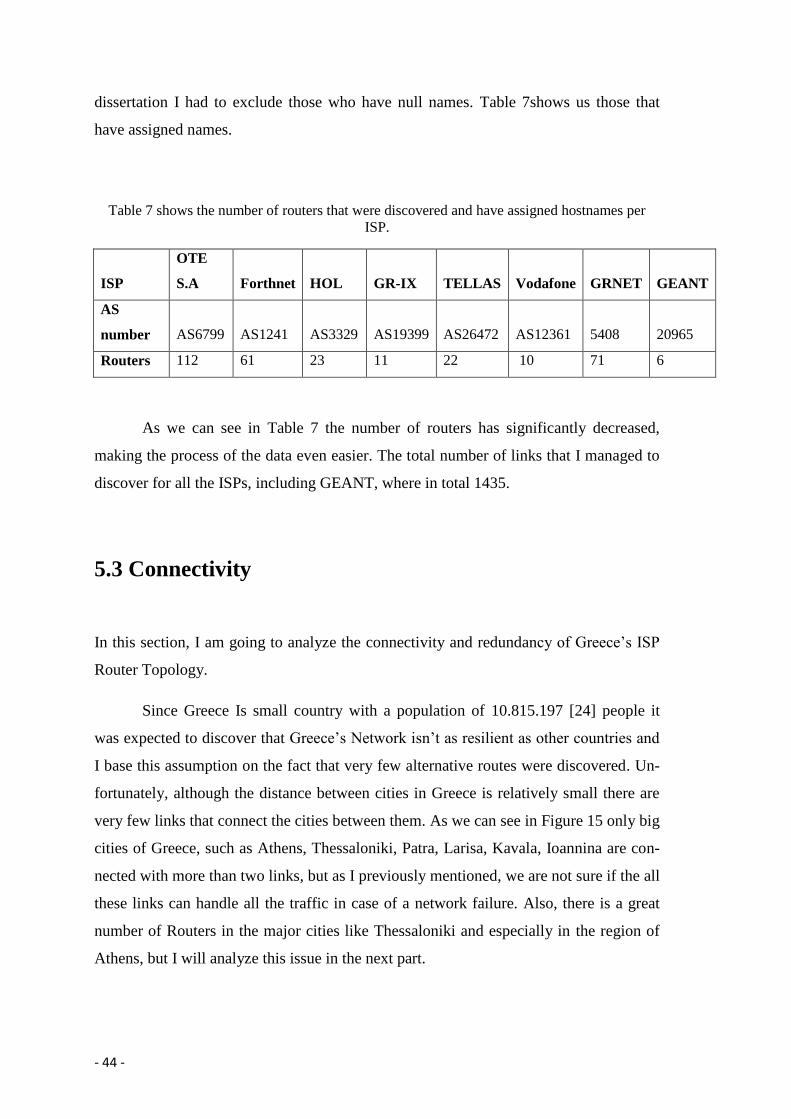
dissertation I had to exclude those who have null names. Table 7shows us those that
have assigned names.
Table 7 shows the number of routers that were discovered and have assigned hostnames per
ISP.
ISP
OTE
S.A Forthnet HOL GR-IX TELLAS Vodafone GRNET GEANT
AS
number AS6799 AS1241 AS3329 AS19399 AS26472 AS12361 5408 20965
Routers 112 61 23 11 22 10 71 6
As we can see in Table 7 the number of routers has significantly decreased,
making the process of the data even easier. The total number of links that I managed to
discover for all the ISPs, including GEANT, where in total 1435.
5.3 Connectivity
In this section, I am going to analyze the connectivity and redundancy of Greece’s ISP
Router Topology.
Since Greece Is small country with a population of 10.815.197 [24] people it
was expected to discover that Greece’s Network isn’t as resilient as other countries and
I base this assumption on the fact that very few alternative routes were discovered. Un-
fortunately, although the distance between cities in Greece is relatively small there are
very few links that connect the cities between them. As we can see in Figure 15 only big
cities of Greece, such as Athens, Thessaloniki, Patra, Larisa, Kavala, Ioannina are con-
nected with more than two links, but as I previously mentioned, we are not sure if the all
these links can handle all the traffic in case of a network failure. Also, there is a great
number of Routers in the major cities like Thessaloniki and especially in the region of
Athens, but I will analyze this issue in the next part.

- 45 -
Another problem that I phased during processing the data was that I was unable
to discover many links between the Islands of Greece and the mainland. I managed to
discover only a few links that half of them corresponded to links between Universities
that belong to the GR-NET [2]. The reason behind this is that many islands of Greece
are deserted or in remote locations. For the larger islands the connection with the main-
land is executed threw fiber optics which are very difficult to implement and those that
are closer to the mainland of Greece the connection is done by using wireless links. Of
course, there are cases where the residents of remote islands use mobile internet connec-
tions or satellite systems.
By reading the above findings is it easy to understand that Greece’s ISP network
is sensitive to failures since its redundancy doesn’t provide the necessary safety in case
of a failure.
5.4 Backbone Topologies
In this section I am going to present a sample of measurements for the backbone topol-
ogies of Internet Service Providers of Greece. The lesson that is learned in this section
is that the backbone design is relatively similar to the POP design.
Figure 22 shows four measured ISP backbones overlaid on a map of Greece. We
can see that backbone topologies, design and policy varies from ISP to ISP. O.T.E S.A
for example, has hubs in all the major cities of Greece while GR-NET has hubs only to
cities that have Educational Institutes and schools. Unfortunately, I was not in a position
to discover more backbone routers in order to have more detailed results.

- 46 -

- 47 -
Figure 22 shows measured backbone topologies of Greece ISPs with inferred geographic loca-
tions from DNS names. From top to bottom. OTE SA, Forthnet, GR-NET, Tellas SA. The
background image is taken from Google Earth.
Not all ISPs were included in this figure since my intention was to prese3nt
those that provided sufficient data.
5.5 POP findings
In this section, I am going to present my findings regarding the POP locations and num-
bers for every ISP.
POP designs are relatively similar in their design. As I previously mentioned
each POP is a physical location where an ISP houses its routers.

- 48 -
Figure 23 shows a sample of a POP topology from GR-NET. The names are the hostnames of
the routers. Most POPs from all ISPs are relatively similar.
There are cases where backbone routers are not connected with full mesh topol-
ogy. This case happens mostly on large POPs. In most of the countries access routers
connect to other ISP routers, including customers to with more than one link. This hap-
pens for security reasons and redundancy. Unfortunately I cannot support this fact for
Greece since I don’t have the required data in order to support this idea.
There are cases that some neighboring routers may not use point-to point links in
order to connect to an access router. Instead a layer 2 device or a multi-access medium
is used in order to aggregate neighboring routers that connect to an access router. Unfor-
tunately traceroute method is unable to recognize whether a point-to-point or a layer 2
link is used.
As an example, figure 23 shows a measured map of GR-NET POP. I chose this
POP since is relatively small and it is very hard to illustrate in details large POPs. It
worth’s also to mention that there are cases where different internet service providers
use the same location in order to house their routers. This thing happens for many rea-
sons; economy is one of them. Also, smaller ISP’s prefer to house their routers into
larger ISP’s infrastructure. For example, many ISP’s house their routers into OTE S.A

- 49 -
infrastructure since smaller ISPs lease lines from OTE SA [25]. The reason behind this
is that OTE S.A is one of the larger ISPs in Greece and many other companies use its
infrastructures.
Table 8 shows in numbers the POPs that I was able to discover from my collect-
ed data, of course, there are more but not all routers provided geographical information.
We clearly see that the most Point of Presences belong to OTE S.A but these could be
completely random since the script that created produced random taceroutes without the
checking if the previous traceoure was executed to the same Autonomous System. Sec-
ond follows the GRNET and third Forthnet.
Table 8 shows the number of POPs discovered per ISP
ISP OTE SA GRNET Forthnet Tellas Panafonet HOL TEE
POPs 16 12 5 6 2 3 1
Since the topology of backbone routers is almost identical to the POP topology
we can say by looking at the Figure 22 that it obvious that ISPs own their POPs into
large cities. This conclusion is based on that no POP was discovered been located in a
small city
5.5.1 Summary
In summary, I can say given the findings I was able to collect that OTE SA leads as far
for the number of Points of Presence but as I mentioned before, I can’t support this ar-
gument with confidence since the number of traceroutes was not equal for every IP
range Also some ISP own more IP ranges than the others.
.

- 50 -
5.6 Router Findings
As I mentioned in previous chapters during the period of collecting data, I managed to
produce 17376 traceroutes which for convenience reasons I had to delete the duplicate
and the traceroutes that offered no useful findings leaving me with almost 2500 trac-
eroutes. These traceroutes led to the discovery of numerous nodes and links. In total, I
managed to discover 983 routers for all the Greek ISPs.
Table 9 shows the in numbers the discovered routers for every case.
Routers Hostnames Geographical Info Total
422 396 979
Table shows the total number of discovered routers, the number of routers that
had assigned hostnames and those that provided geographical information.
5.7 Redundancy
In this section, I am going to present and analyze the redundancy of Greece’s ISP topol-
ogy. In the beginning I would like to say that the data that I managed to collect were
sufficient enough in order to fully support my opinion in this matter. In the sections that
follows I am presenting the redundancy of OTE SA and GRNET.
5.7.1 OTE SA Network
Almost in all cases ISP router topologies around the world are using a full mesh topolo-
gy as shown in Figure 24. I chose to show the OTE SA router topology map since I was
able to discover the most routers including geographical location.

- 51 -
Figure 24 shows the POP topology of the O.T.E S.A ISP. Lines that are thicker based on the
traffic that they manage. Figure doesn’t show city names since I only wanted to show the topol-
ogy.
As shown in figure 24 we can see that OTE SA POP topology map is using a
full mesh topology in order to connect different POPs around Greece. As I mentioned
before, I wasn’t able to collect as much data as I wanted in order to have a clearer image
on the redundancy of Greece’s network. We can see that most POPs (cities) have more
than one link connecting them to other POPs that could be used as back up routes in
case of failure. For example, we can see that Larisa is connected with Thessaloniki,
Athens, Patra and the island of Mytilini. Also Thessaloniki is directly connected to Ath-
ens, but also has a link that goes through Ioannina, Larisa and ends in Athens. So based
on those findings, we can say that we have a redundant network. Since we don’t have
data about the network capacity, we cannot say for sure how this network will behave in
case of a failure.
Supposing that the whole network of Greece was the network shown in figure 24
from a first look we could say that this topology is redundant and can handle most of the

- 52 -
failures that could occur, but just looking at the topology map doesn’t provide us
enough information in order to support this with certainty, since we are not in a position
to know how much traffic these links can handle. For example, if the direct link be-
tween Thessaloniki and Athens fails, we could suppose that all the data traveling from
Athens to Thessaloniki and vice versa could be forwarded through Ioannina and Patra in
order to reach their destination, but known that the failed link connects the biggest and
most populated cities in Greece, we cannot say with certainty that the backup link will
behave normally and even if it does the QoS(Quality of Service) at the end users might
significantly decrease.
Another peculiarity that Greece has, is the number of islands. Of course, many
of those are remote and deserted and those that are settled might be very far from the
mainland. Unfortunately again the data that I managed to collect doesn’t allow me to
make certain conclusions but only speculations. It is easy to say that it is not expected
all the islands of Greece to be connected with fiber optic cables, but even if they were it
would be very difficult and expensive to have many back up routes. In this case, failures
are very difficult to handle since if a failure occurs with no back up routes it would be
very likely to be left without a connection.
5.7.2 GRNET Network Topology
In this section, I am going to present the redundancy of GRNET network. As previously
mentioned, I was not able to collect sufficient amount of data so I am going to use the
data that are published on the GRNET home page.
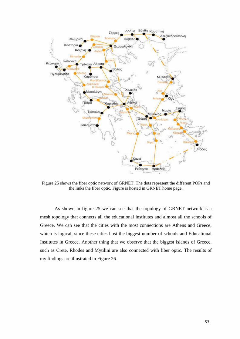
- 53 -
Figure 25 shows the fiber optic network of GRNET. The dots represent the different POPs and
the links the fiber optic. Figure is hosted in GRNET home page.
As shown in figure 25 we can see that the topology of GRNET network is a
mesh topology that connects all the educational institutes and almost all the schools of
Greece. We can see that the cities with the most connections are Athens and Greece,
which is logical, since these cities host the biggest number of schools and Educational
Institutes in Greece. Another thing that we observe that the biggest islands of Greece,
such as Crete, Rhodes and Mytilini are also connected with fiber optic. The results of
my findings are illustrated in Figure 26.

- 54 -
Figure 26 shows the discovered network of GRNET
As far for the redundancy of GRNET network, we can see that the connections
between the islands can offer redundancy since there are alternative routes that the traf-
fic can follow in case of a network failure. On the other hand, we can’t support the same
argument for Northern Greece, since we can see that there is only one link that connects
Thessaloniki to Alexandroupoli and only speculations can be made about what will
happen in case of failure. Of course, there must be a backup that connects these cities,
but in case that this also fails, there is no obvious route to follow.
5.7.3 Summary
The reason that I chose to present these two ISP’s was that the data that I managed to
gather didn’t allow me to discuss the redundancy of other ISP networks. Also, as I pre-
viously mentioned the Internet is relatively new to Greece and during the last years

- 55 -
ISP’s are making efforts to connect as many locations as possible. It worth’s to mention
that still there are many remote villages in Greece that connect to the Internet through
wireless technologies or they might not even have any connection at all. Usually this
happens to locations that have high altitude or to remote islands.
Increasing the redundancy of Greece’s network is an expensive and difficult job
and the reason behind this is the morphology of Greece. We should only consider that
Greece owns over 6000 islands, of course not all of them are inhabited, only 227 but we
should think that they are scattered all around the Aegean and the Ionian Pelagos mak-
ing the connection even more difficult. During the past year large ISPs in Greece started
to offer satellite solutions to customers [26] but regardless from the fact that the prices
are relatively high, it will give the opportunity for Internet access even to the most re-
mote places of Greece. Though this is a good solution these satellite links can’t increase
the redundancy of Greece’s Network, since there are many issues, such as latency and
bandwidth during the rush hours.
5.8 Traffic Crossroad
In this section is presented the role that Greece plays to the Internet Topology Globally.
As previously mentioned, I relocated my script into a different server but in par-
allel I left the original script running for a period of three months in Amazon’s Server.
Through this process I wanted to discover whether any traffic will be forwarded through
Greek Internet Service Providers. During this period, the server executed more than
51840 traceroutes to IP addresses located all around the world. Again, although the pe-
riod was significantly larger very few traceroutes were executed targeting Greek IP ad-
dresses, but as I mentioned before the intention was to see whether Greece serves traffic
destined to other countries.
Again the results were not encouraging since only a couple of traceroutes probed
Greek Routers and in both cases the targeted IP addresses belonged to Kuwait. Analyz-
ing the facts, we can support that unlike the Geostrategic location Greece plays a small
role in the World Wide Web. Of course, we don’t know for sure what will happen in
case of a network failure and if Greece will act as a backup route.


- 57 -
6. Conclusions and future work
In this chapter, I review this thesis and describe future work in network meas-
urement.
6.1 Conclusions
In this section, I am about to present the conclusions that I came up during the gather-
ing, the process and the visualization of my collected data.
6.1.1 Gathering of data
As mentioned in the methodology chapter, the first thing that I should perform was the
creation of a script that would randomly select an IP range from a given list and then
perform a traceroute to a targeted random IP from the selected IP range.
Through trial and error, I can say with confidence that as previous researchers
that used the traceroute method for mapping ISP router topology, it is possible and effi-
cient to collect the data required for this task. Of course, the success of this effort relies
on the choices that will be made by the researcher. These choices have to do with the
way that the traceroutes are produced and the choice of server.
6.1.2 Processing the data
The process of the data is not an easy task since the amount of data is enormous and a
lot of precaution is required. The most challenging task was to find a way on how to
process the data without losing any critical information. Again the success of this effort
relies completely the way that the researchers approach this effort.

- 58 -
6.1.3 Visualization of data
The visualization of data can be performed in various ways, since there are many and
different softwares that provide this ability. The most difficult part of this effort was to
find a way to add geographical information for every router. Gephi software gave me
this ability.
6.2 Future works
The work presented in this dissertation gave me the ability to understand different tech-
niques that have used and to add my contribution in the effort of my mapping ISPs To-
pology network.
In this chapter, I am going to present ideas that will help me to improve any fu-
ture effort on mapping Greece’s Network Infrastructure.
As was presented in my findings the approach of using one server to try to map
the network topology, although it was proven correct, it did not provide me sufficient
data in order to support my arguments with more confidence. Therefore, I strongly be-
lieve that it would be better to use multiple servers located around Greece. Also, these
servers would be best if they belonged to different Autonomous Systems. Of course,
this approach would require many resources that translate to money. To overcome this
problem I will try to find volunteers that are willing to host and run my script for a cer-
tain time period. In this way I will be able to probe Greece’s Network from multiple
vantage points, providing a more detailed image.
Another matter that I faced was the amount of unnecessary data produced by my
traceroute policy. I had to exclude many duplicate traceroutes and also many did not
provide routers geographical information. Thus the next step is to insert inside my script
a command that will check if the targeted IP address contains this information. This ap-
proach will also provide me more “useful” traceroutes and will exclude those that don’t
provide geographical information or routers that are end-hosts. Also in the future, I will
try to perform equal traceroutes for every IP range. In this way, all IP ranges will be
“tracerouted” in an even way and the randomization will be reduced.

- 59 -
Bibliography
[1] Bolt Beranek and Newman Inc,, "A History of ARPANET: The fist decade," Defenced
Advanced Research Projects Agency., 1981.
[2] Greek Research and Technology Network, "grnet," [Online]. Available:
https://www.grnet.gr/en.
[3] Y. Rekhter and L. Tony, "A border gateway protocol 4 (BGP-4)," Internet Engineering Task
Force Request for Comments RFC-1771, 1995.
[4] M. Caserar and J. Rexforf, BGP Routing Policies in ISP Networks.
[5] Eric C. Rosen, Bolt Beranek and Newman Inc, "EXTERIOR GATEWAY PROTOCOL (EGP),"
1982.
[6] David Meyer. University of Oregon , 1999. [Online]. Available: http://routevies.org.
[7] L. Peterson and A. Nakao, "BGP feed configuration memo. Technical Report PDN–03–
011," PlanetLab Consortium, 2003.
[8] L. Peterson, T. Anderson, D. Culler and T. Roscoe, A blueprint for introducing disruptive
technology into the Internet. In Proceedings of the ACM Workshop on Hot Topics in
Networks (HotNets), NJ: Princeton, 2002, p. 59–64.
[9] V. Jacobnson. [Online]. Available: ftp://ftp.ee.lbl.gov.
[10] K. Sangmin and H. Khaled, Efficient Estimation of More Detailed Internet IP Maps.,
Department of Computer Science North Carolina.
[11] N. Spring, R. Mahajan, D. Wetherall and T. Anderson, Measuring ISP Topologies With
Rocketfuel.
[12] J. Grand and D. Pansiot, On routes and multicast trees in the Internet, ACM SIGCOMM<
Comput, Commun, 1998, pp. 41-50.
[13] "American Registry for Internet Numbers," [Online]. Available: https://www.arin.net/.
[14] "APNIC," [Online]. Available: http://www.apnic.net/.
[15] "RIPE Network Coordination Centre," [Online]. Available: http://www.ripe.net/.
[16] P. Mockapetris, "DOMAIN NAMES - CONCEPTS AND FACILITIES, RFC 1034," 1987.

- 60 -
[17] R. Govindan, and H. Tangmunarunkit, "Heuristics for internet map," IEEE INFOCOM 2000,,
p. 1371–1380, March 2000.
[18] P. Maigron, "Regional Internet Registries Statistics," [Online]. Available: http://www-
public.it-sudparis.eu/~maigron/RIR_Stats/.
[19] "Cisco," Cisco Technologies, [Online]. Available:
http://www.cisco.com/c/en/us/products/routers/7609-router/index.html. [Accessed
2014].
[20] "Greek Internet Exchange Service," [Online]. Available: GR-IX .
[21] "Forthnet," [Online]. Available: Forthnet .
[22] "Vodafone Greece," [Online]. Available: http://www.vodafone.gr/.
[23] "GEANT," [Online]. Available: http://www.geant.net/.
[24] "statistics.gr," 28 December 2012. [Online]. Available:
http://www.statistics.gr/portal/page/portal/ESYE/BUCKET/General/A1602_SAM01_DT_D
C_00_2011_02_F_GR.pdf. [Accessed 2014].
[25] EETT, December 2007. [Online]. Available:
http://www.eett.gr/opencms/export/sites/default/admin/downloads/Consultations/tele
coms/ades_prosv_ston_topiko_brogxo/TROPOPOIHSH_RUO_DD.pdf. [Accessed 2014].
[26] "OTE SATELITE," 2014. [Online]. Available:
https://www.ote.gr/en/web/guest/consumer/products-services/ote-satellite-internet.
[27] "IT Services," Internation Hellenic University, 2007. [Online]. Available:
http://www.itc.ihu.edu.gr/. [Accessed 2014].
[28] [Online]. Available: https://www.ote.gr/.

- 61 -
APPENDIX
Table 10 shows discovered Internet Service Providers and their Autonomous Systems.
A.S I.S.P
5408 Grnet
1241 forthnet
41920 ONTELECOMS
12361 PANAFONET
8396 TEE-GR
3329 HOL-GR
25472 TELLAS
702 Verizon
6799 Ote SA
1299 TELIANET
24735 Antenna S.A,GR
5408 Grnet
198477 MEDGR-NET
8670 University of Sarajevo
198188 MTEL,GR
1299 TELIANET
12653 Impuls Hellas S.A.
5522 OMNITEL
3491 Beyond The Network America,
2119 Telenor Norge AS
20965 GEANT DANTE Ltd
2852 CESNET2
24897 QTELECOM-AS
702 Verizon
8643 University of Athens
174 Cogent Communications,US
199399 GR-IX-AS
199789 ETHERLAND
6866 Cyta
702 Verizon
198252 ELTAKABEL-AS
174 Cogent Communications,US
198497 ACSELEKTRONIK
3356 Level 3 Communications
8280 SYNAPSECOM S.A,GR

- 62 -
1654 Skogen Network,SE
16022 COSMOLINE TELECOMMUNICATION
SERVICES
15544 Dataways Hellas
Script
ip=$(shuf -n 1 < ips.txt)
echo $ip
thir=7
four=3
fif=7
sev=127
eig=63
nin=31
twen=15
tone=7
ttwo=3
high=255
sub="${ip##*/} " x="${ip%/*}"
ip4="${x##*.}" ; x="${x%.*}"
ip3="${x##*.}" ; x="${x%.*}"
ip2="${x##*.}" ; x="${x%.*}"
ip1="${x##*.}"
echo "THE SUBNET IS /$sub"
#echo "IP IS $x"
echo " 4TH PART $ip4"
echo " 3TH PART $ip3"
echo " 2TH PART $ip2"
echo " 1TH PART $ip1"
echo "THE IP RANGE IS $ip1.$ip2.$ip3.$ip4/$sub"
- 63 -
if [ $sub -eq 13 ];
then ip2h=$(($thir + $ip2))
ip3h=$(($high + $ip3))
ip4h=$(($high + $ip4))
echo "MAXIMUM $ip1.$ip2h.$ip3h.$ip4h"
ip2r=$(shuf -i $ip2-$ip2h -n 1)
ip3r=$(shuf -i $ip3-$ip3h -n 1)
ip4r=$(shuf -i $ip4-$ip4h -n 1)
echo "TRACE ROUTING TO: $ip1.$ip2r.$ip3r.$ip4r"
traceroute $ip1.$ip2r.$ip3r.$ip4r >> logfilev2.txt
elif [ $sub -eq 14 ];
then ip2h=$(($four + $ip2))
ip3h=$(($high + $ip3))
ip4h=$(($high + $ip4))
echo "MAXIMUM $ip1.$ip2h.$ip3h.$ip4h"
ip2r=$(shuf -i $ip2-$ip2h -n 1)
ip3r=$(shuf -i $ip3-$ip3h -n 1)
ip4r=$(shuf -i $ip4-$ip4h -n 1)
echo "TRACE ROUTING TO: $ip1.$ip2r.$ip3r.$ip4r"
traceroute $ip1.$ip2r.$ip3r.$ip4r >> logfilev2.txt
elif [ $sub -eq 15 ];
then ip3h=$(($fif + $ip3))
ip4h=$(($high + $ip4))
echo "MAXIMUM $ip1.$ip2.$ip3h.$ip4h"
ip3r=$(shuf -i $ip3-$ip3h -n 1)
ip4r=$(shuf -i $ip4-$ip4h -n 1)
echo "TRACE ROUTING TO: $ip1.$ip2.$ip3r.$ip4r"
traceroute $ip1.$ip2.$ip3r.$ip4r >> logfilev2.txt
elif [ $sub -eq 16 ];
then ip3h=255
ip4h=255

- 64 -
echo "MAXIMUM $ip1.$ip2.$ip3h.$ip4h"
ip3r=$(shuf -i $ip3-$ip3h -n 1)
ip4r=$(shuf -i $ip4-$ip4h -n 1)
echo "TRACE ROUTING TO: $ip1.$ip2.$ip3r.$ip4r"
traceroute $ip1.$ip2.$ip3r.$ip4r >> logfilev2.txt
elif [ $sub -eq 17 ];
then ip3h=$(($sev + $ip3))
ip4h=255
if [ $ip3h -gt 255 ];
then ip3h=255
fi
echo "MAXIMUM $ip1.$ip2.$ip3h.$ip4h"
ip3r=$(shuf -i $ip3-$ip3h -n 1)
ip4r=$(shuf -i $ip4-$ip4h -n 1)
echo "TRACE ROUTING TO: $ip1.$ip2.$ip3r.$ip4r"
traceroute $ip1.$ip2.$ip3r.$ip4r >> logfilev2.txt
elif [ $sub -eq 18 ];
then ip3h=$(($eig + $ip3))
ip4h=255
if [ $ip3h -gt 255 ];
then ip3h=255
fi
echo "MAXIMUM $ip1.$ip2.$ip3h.$ip4h"
ip3r=$(shuf -i $ip3-$ip3h -n 1)
ip4r=$(shuf -i $ip4-$ip4h -n 1)
echo "TRACE ROUTING TO: $ip1.$ip2.$ip3r.$ip4r"
traceroute $ip1.$ip2.$ip3r.$ip4r >> logfilev2.txt
elif [ $sub -eq 19 ];

- 65 -
then ip3h=$(($nin + $ip3))
ip4h=255
if [ $ip3h -gt 255 ];
then ip3h=255
fi
echo "MAXIMUM $ip1.$ip2.$ip3h.$ip4h"
ip3r=$(shuf -i $ip3-$ip3h -n 1)
ip4r=$(shuf -i $ip4-$ip4h -n 1)
echo "TRACE ROUTING TO: $ip1.$ip2.$ip3r.$ip4r"
traceroute $ip1.$ip2.$ip3r.$ip4r >> logfilev2.txt
elif [ $sub -eq 20 ];
then ip3h=$(($twen + $ip3))
ip4h=255
if [ $ip3h -gt 255 ];
then ip3h=255
fi
echo "MAXIMUM $ip1.$ip2.$ip3h.$ip4h"
ip3r=$(shuf -i $ip3-$ip3h -n 1)
ip4r=$(shuf -i $ip4-$ip4h -n 1)
echo "TRACE ROUTING TO: $ip1.$ip2.$ip3r.$ip4r"
traceroute $ip1.$ip2.$ip3r.$ip4r >> logfilev2.txt
elif [ $sub -eq 21 ];
then ip3h=$(($tone + $ip3))
ip4h=255
if [ $ip3h -gt 255 ];
then ip3h=255
fi
echo "MAXIMUM $ip1.$ip2.$ip3h.$ip4h"
ip3r=$(shuf -i $ip3-$ip3h -n 1)
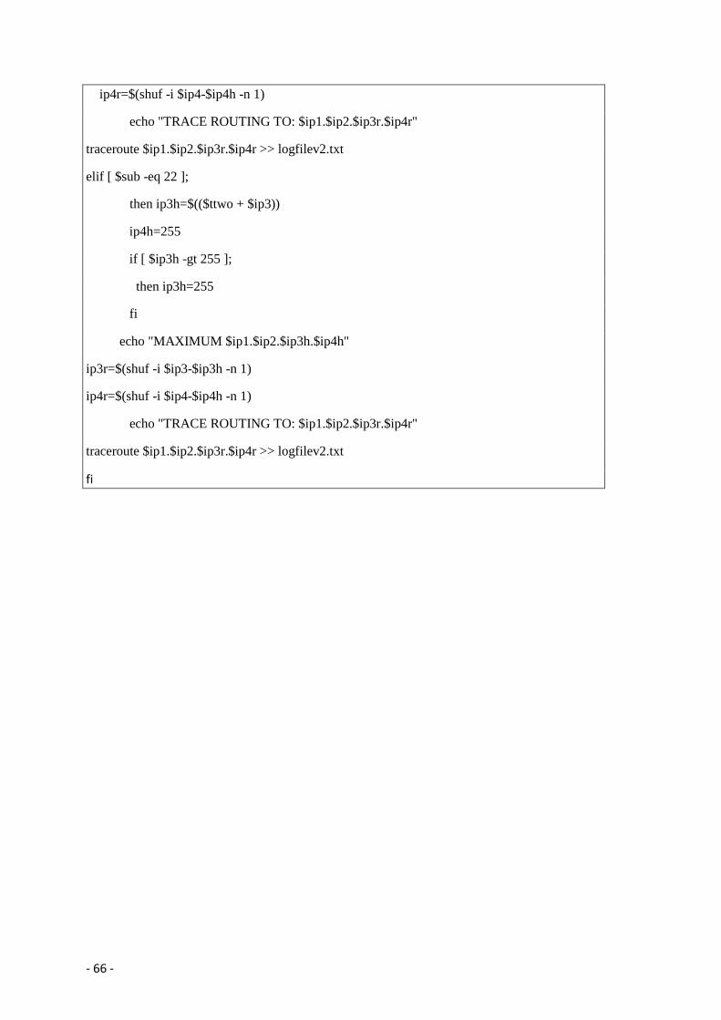
- 66 -
ip4r=$(shuf -i $ip4-$ip4h -n 1)
echo "TRACE ROUTING TO: $ip1.$ip2.$ip3r.$ip4r"
traceroute $ip1.$ip2.$ip3r.$ip4r >> logfilev2.txt
elif [ $sub -eq 22 ];
then ip3h=$(($ttwo + $ip3))
ip4h=255
if [ $ip3h -gt 255 ];
then ip3h=255
fi
echo "MAXIMUM $ip1.$ip2.$ip3h.$ip4h"
ip3r=$(shuf -i $ip3-$ip3h -n 1)
ip4r=$(shuf -i $ip4-$ip4h -n 1)
echo "TRACE ROUTING TO: $ip1.$ip2.$ip3r.$ip4r"
traceroute $ip1.$ip2.$ip3r.$ip4r >> logfilev2.txt
fi