Map Projections Francisco Olivera, Ph.D., P.E. Srikanth Koka Department of Civil Engineering Texas...
48
Map Projections Francisco Olivera, Ph.D., P.E. Srikanth Koka Department of Civil Engineering Texas A&M University
-
date post
21-Dec-2015 -
Category
Documents
-
view
217 -
download
2
Transcript of Map Projections Francisco Olivera, Ph.D., P.E. Srikanth Koka Department of Civil Engineering Texas...

Map Projections
Francisco Olivera, Ph.D., P.E.Srikanth Koka
Department of Civil EngineeringTexas A&M University
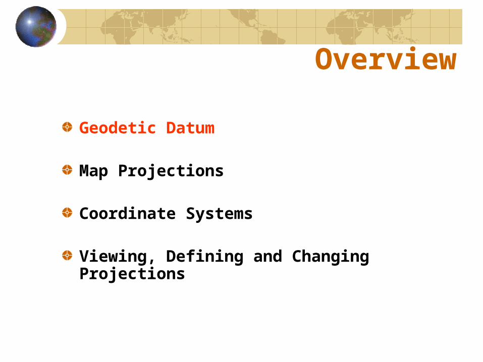
Overview
Geodetic Datum
Map Projections
Coordinate Systems
Viewing, Defining and Changing Projections

Shape of the Earth
We think of the earth as a sphere ...
... when it is actually an ellipsoid, slightly larger in
radius at the equator than at the poles.

Definitions
A geodetic datum defines the size and shape of the earth and the origin and orientation of the axis used to define the location of points.
Over time, geodetic data have evolved from simple flat surfaces to spheres to complex ellipsoids.
Flat earth models can be accurate for short distances (i.e., less than 10 km), spherical earth models for approximate global distance calculations, and ellipsoidal earth models for accurate global distance calculations.

O a
b
X
Ellipse
An ellipse is defined by:Focal length = Flattening ratio: f = (a-b)/aDistance F1-P-F2 is constant for all points P on ellipseWhen = 0 then ellipse = circle
For the earth:Major axis: a = 6378 kmMinor axis: b = 6357 kmFlattening ratio: f = 1/300
Z
F1 F2
P

Ellipsoid or Spheroid
O
X
Z
Ya ab
Rotational axis
Rotate an ellipse around one of its axis.

Standard Ellipsoids
Ellipsoid Major axis, a (m)
Minor axis, b (m)
Flattening ratio, f
Clarke (1866) 6,378,206 6,356,584 1/294.98
GRS80 6,378,137 6,356,752 1/298.57
Ref: Snyder, Map Projections, A working manual, USGS Professional Paper 1395, p.12

Standard Horizontal Geodetic Data
NAD27 (North American Datum of 1927) uses the Clarke (1866) ellipsoid.
NAD83 (North American Datum of 1983) uses the GRS80 ellipsoid.
WGS84 (World Geodetic System of 1984) uses GRS80.

Earth Surfaces
Geoid is a surface of constant gravity.
Topographic surface
EllipsoidSea surface
Geoid

Earth Surfaces
Ocean
Geoid
Topographic surface
EllipsoidGravity Anomaly
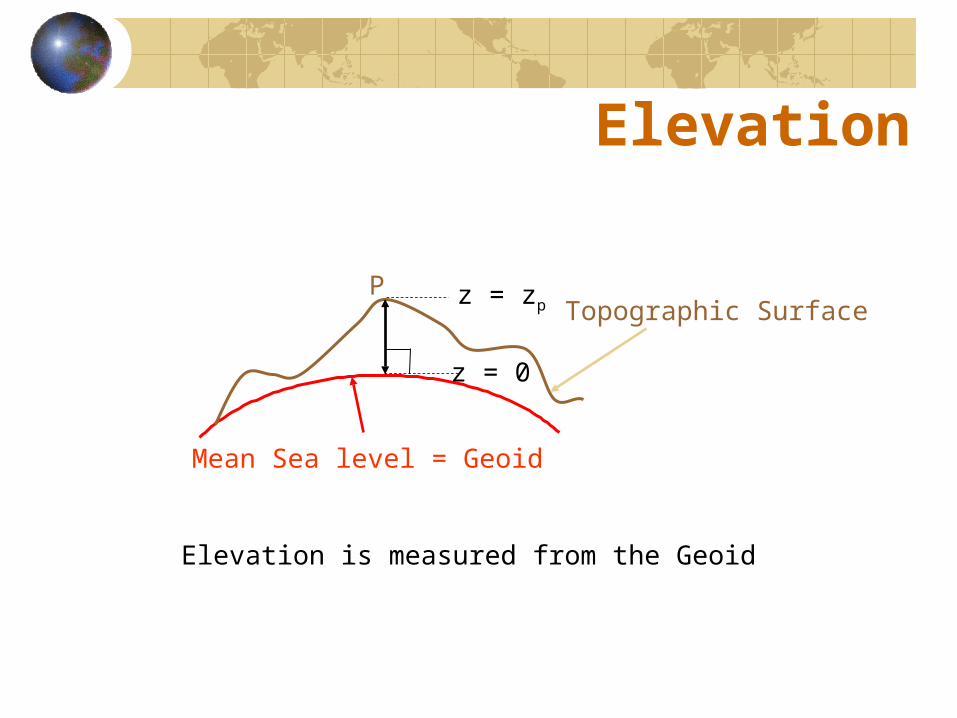
Elevation
P z = zp
z = 0
Mean Sea level = Geoid
Topographic Surface
Elevation is measured from the Geoid

Standard Vertical Geodetic Data
A vertical datum defines elevation z, taking into account a map of gravity anomalies between the ellipsoid and the geoid.
NGVD29 (National Geodetic Vertical Datum of 1929)
NAVD88 (North American Vertical Datum of 1988)
Overview
Geodetic Datum
Map Projections
Coordinate Systems
Viewing, Defining and Changing Projections

Map Projections
A map projection is a mathematical algorithm to transform locations defined on the curved surface of the earth into locations defined on the flat surface of a map.
The earth is first reduced to a globe and then projected onto a flat surface.

Map Projection
Representative Fraction
Globe distanceEarth distance
Scale Projection
(e.g. 1:24,000) (e.g. 0.9996)
Scale Fraction
Map distanceGlobe distance
Map Distortion
In the process of transforming a curved surface into a flat surface, some geometric properties are modified.
The geometric properties that are modified are:Area (important for mass balances)ShapeDirectionLength
The difference between map projections has to do with which geometric properties are modified.
Depending on the type of analysis, preserving one geometric property might be more important than preserving another.

Map Distortion
Conformal projections: Preserves shapes.
Equal area projections: Preserves area.
Equidistant projections: Preserves the distances between certain points.

Types of Projections
Conic: Screen is a conic surface. Lamp at the center of the earth. Examples: Albers Equal Area, Lambert Conformal Conic. Good for East-West land areas.
Cylindrical: Screen is a cylindrical surface. Lamp at the center of the earth. Example: Transverse Mercator. Good for North-South land areas.
Azimuthal: Screen is a flat surface tangent to the earth. Lamp at the center of the earth (gnomonic), at the other side of the earth (stereographic), or far from the earth (orthographic). Examples: Lambert Azimuthal Equal Area. Good for global views.

Conic Projections
Albers and Lambert

Cylindrical Projections
Transverse
Oblique
Tangent Secant
Mercator

Azimuthal
Lambert

Albers Equal-Area Conic
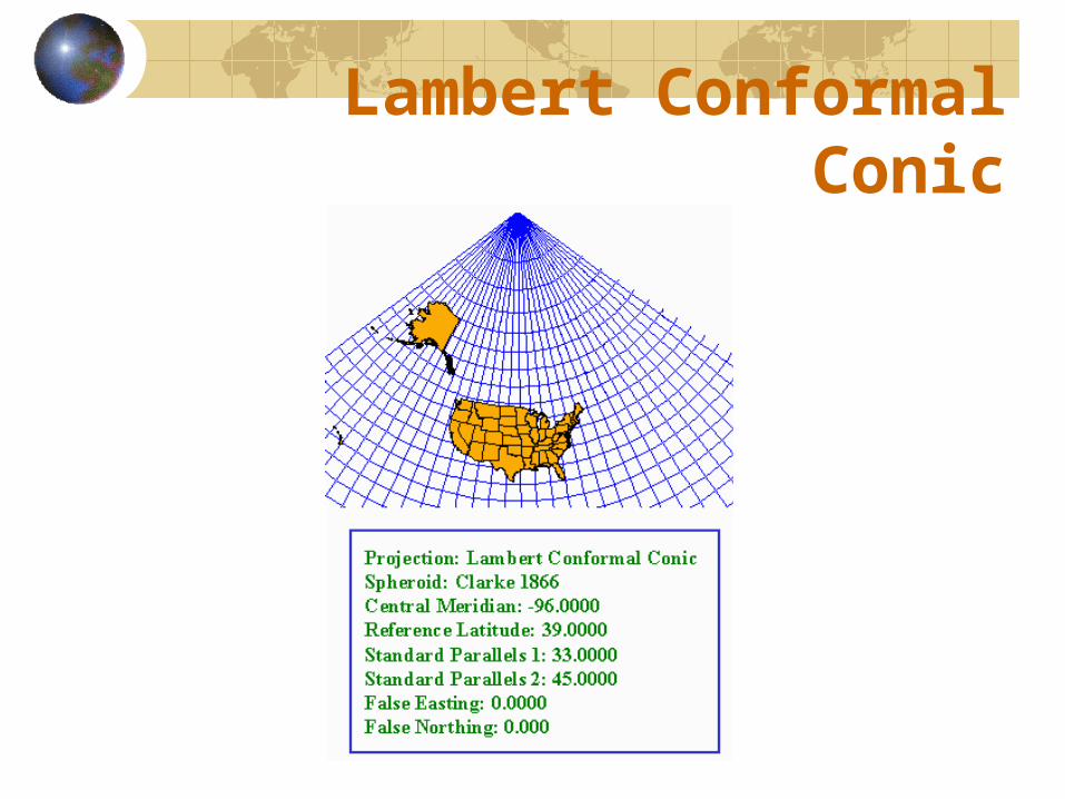
Lambert Conformal Conic

Universal Transverse Mercator

Lambert Azimuthal Equal-Area
Overview
Geodetic Datum
Map Projections
Coordinate Systems
Viewing, Defining and Changing Projections

Coordinate Systems
A coordinate system is used to locate a point of the surface of the earth.

Coordinate Systems
Global Cartesian coordinates (x, y, z) for the whole earth
Geographic coordinates (,, z) for the whole earth
Projected coordinates (x, y, z) on a local area of the earth’s surface

Global Cartesian Coordinates
O
X
Z
Y
GreenwichMeridian
Equator
•

Geographic Coordinates
90 W120 W 60 W
30 N
0 N
60 N

Geographic Coordinates
Longitude line (Meridian)
N
S
W E
Range: 180ºW - 0º - 180ºE
Latitude line (Parallel)
Range: 90ºS - 0º - 90ºN
N
S
W E
(0ºN, 0ºE) Equator, Prime Meridian

Geographic Coordinates
Earth datum defines the standard values of the ellipsoid and geoid.
Latitude () and longitude () are defined using an ellipsoid.
Elevation (z) is defined using a geoid.

Latitude Take a point S on the surface of the ellipsoid and define there the tangent plane mn.
Define the line pq through S and normal to the tangent plane.
Angle pqr is the latitude , of point S.
Sm
n
q
p
r

If Earth were a Sphere ...
Length on a Meridian:AB = R (same for all latitudes)
Length on a Parallel: CD = r = R Cos (varies with latitude) 0 N R
rr
A
BC
D

Example:What is the length of a 1º increment on a meridian and on a parallel at 30N, 90W? Radius of the earth R = 6370 km.
Solution: • A 1º angle has first to be converted to radians: radians = 180°, so 1º = /180° = 3.1416/180° = 0.0175 radians
• For the meridian: L = R = 6370 Km * 0.0175 = 111 km
• For the parallel: L = R Cos= 6370 * Cos30° * 0.0175 = 96.5 km
• Meridians converge as poles are approached
If Earth were a Sphere ...

Cartesian CoordinatesA planar cartesian coordinate system is defined by a pair of orthogonal (x, y) axes drawn through an origin.
(o, o)(xo, yo)
X
Y
Origin

Coordinate Systems
Universal Transverse Mercator (UTM) - a global system developed by the US Military Services.
State Plane - civilian system for defining legal boundaries.

Universal Transverse Mercator
Uses the Transverse Mercator projection.
60 six-degree-wide zones cover the earth from East to West starting at 180° West.
Each zone has a Central Meridian (o).
Reference Latitude (o) is the equator.
(Xshift, Yshift) = (xo,yo) = (500,000, 0).
Units are meters.
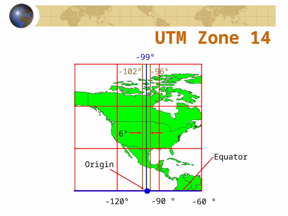
UTM Zone 14
Equator
-120° -90 ° -60 °
-102° -96°
-99°
Origin
6°

State Plane
Defined for each state or part of a state in the United States
Texas has five zones (North, North Central, Central, South Central and South) to give accurate representation.
East-West States (e.g. Texas) use Lambert Conformal Conic; North-South States (e.g. California) use Transverse Mercator
Greatest accuracy for local measurements

Overview
Geodetic Datum
Map Projections
Coordinate Systems
Viewing, Defining and Changing Projections
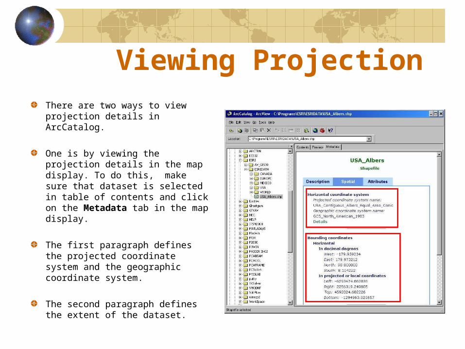
Viewing Projection There are two ways to view projection details in ArcCatalog.
One is by viewing the projection details in the map display. To do this, make sure that dataset is selected in table of contents and click on the Metadata tab in the map display.
The first paragraph defines the projected coordinate system and the geographic coordinate system.
The second paragraph defines the extent of the dataset.
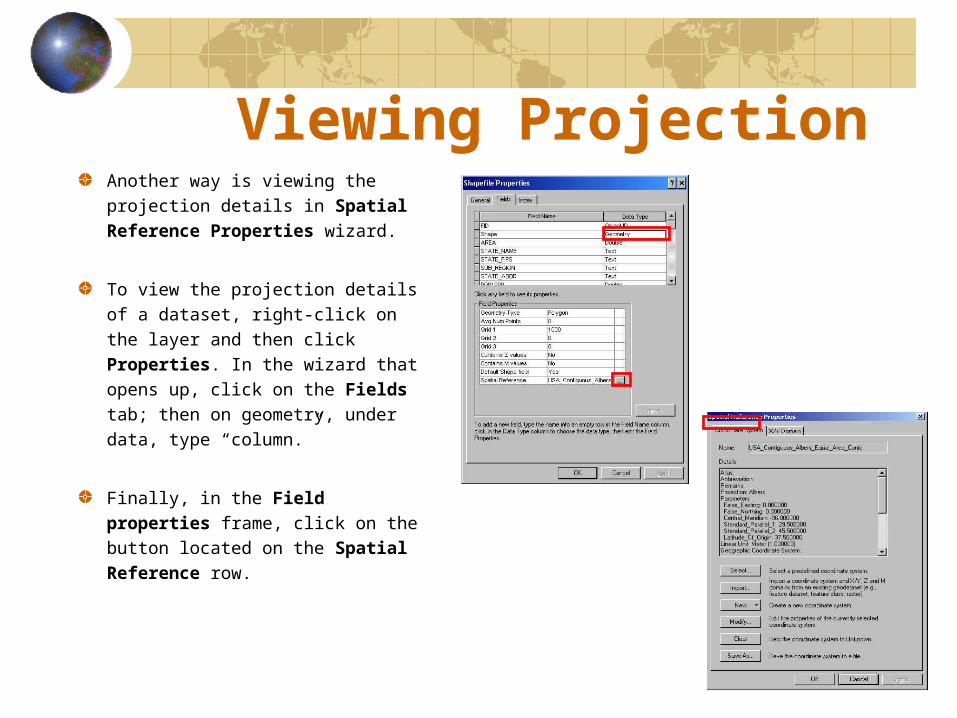
Viewing Projection Another way is viewing the projection details in Spatial Reference Properties wizard.
To view the projection details of a dataset, right-click on the layer and then click Properties. In the wizard that opens up, click on the Fields tab; then on geometry, under data, type “column.”
Finally, in the Field properties frame, click on the button located on the Spatial Reference row.

Viewing Projection
Defines the extent of the shapefile and feature class.

Defining ProjectionBefore moving feature classes into a feature dataset, the spatial reference of the feature dataset should be defined.
In the Spatial Reference Properties wizard:
Select can be used to select a coordinate system available.
Import can be used to define the projection using an existing projection from a feature dataset, feature class or shape file.
New can be used to assign custom projection.

Projecting On-The-FlyEach data frame in an ArcMap document has its own projection.
The projection of the data frame can be defined using Data Frame Properties/Coordinate System.
Data (with map projection defined) added to a data frame is re-projected on-the-fly to the data frame’s projection.
A layer in a data frame can be exported either with its original projection or with data frame’s projection.

Defining and Changing the Projection
ArcToolBox contains tools for data conversion and data management.
Projection definition and projection change can be accomplished using ArcToolBox
ArcCatalog can also be used for defining the data projection.

Projecting Data
ArcToolBox can be used for changing projections.
To change the projection of a dataset, its original coordinate system should be known.