
MANUFACTURING TECHNOLOGY - BrainZorp · PDF fileUNIT – II Hot & Cold Working –...
50
UNIT – II Hot & Cold Working – Forging & Rolling MANUFACTURING TECHNOLOGY Department of Automobile Engineering
-
Upload
truongmien -
Category
Documents
-
view
218 -
download
3
Transcript of MANUFACTURING TECHNOLOGY - BrainZorp · PDF fileUNIT – II Hot & Cold Working –...

UNIT – II
Hot & Cold Working – Forging & Rolling
MANUFACTURING TECHNOLOGY
Department of Automobile Engineering

Manufacturing Technology Mechanical Working of Metals
In this method no machining process is carried out, but it is used
to achieve optimum mechanical properties in the metal.
The wastage of material in metal working process is negligible or
very small. But the production is very high compared to other
process.
Department of Automobile Engineering

Manufacturing Technology Types of Metal Working or Processing Methods
• Mechanical processing
– Hot working
– Cold working
• Thermal processing
– Annealing
• Recovery, recrystallization and growth
– Heat treatments
• Both of these are used to control properties of the final product
Department of Automobile Engineering

Hot Working: T>0.5Tm
• Mechanical working of a metal above the recrystallization
temperature but below the melting point is known as hot working.
• The temperature at which the complete recrystallization of a metal
take place with in a specified time
• The recrystallization temperature of metal will be about 30 to 40% of
its melting temperature.
Types
• Forging
• Rolling
• Extrusion
• Drawing
Manufacturing Technology
Department of Automobile Engineering
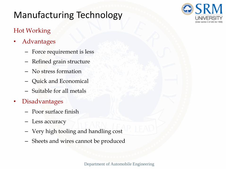
Hot Working
• Advantages
– Force requirement is less
– Refined grain structure
– No stress formation
– Quick and Economical
– Suitable for all metals
• Disadvantages
– Poor surface finish
– Less accuracy
– Very high tooling and handling cost
– Sheets and wires cannot be produced
Manufacturing Technology
Department of Automobile Engineering

Cold Working :T<0.3Tm
Mechanical working of a metal below the recrystallization
temperature (Room Temperature) is known as cold working.
Reduces the amount of plastic deformation that a material can
undergo in subsequent processing and requires more power for
further working
Types
Drawing
Squeezing
Bending
Manufacturing Technology
Department of Automobile Engineering
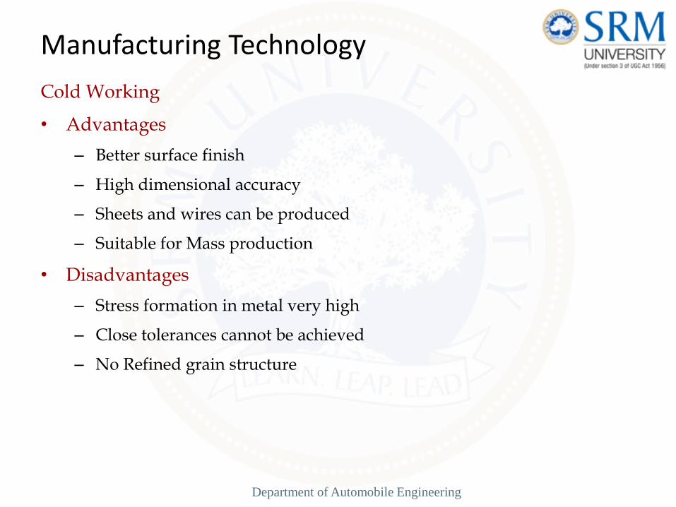
Cold Working
• Advantages
– Better surface finish
– High dimensional accuracy
– Sheets and wires can be produced
– Suitable for Mass production
• Disadvantages
– Stress formation in metal very high
– Close tolerances cannot be achieved
– No Refined grain structure
Manufacturing Technology
Department of Automobile Engineering
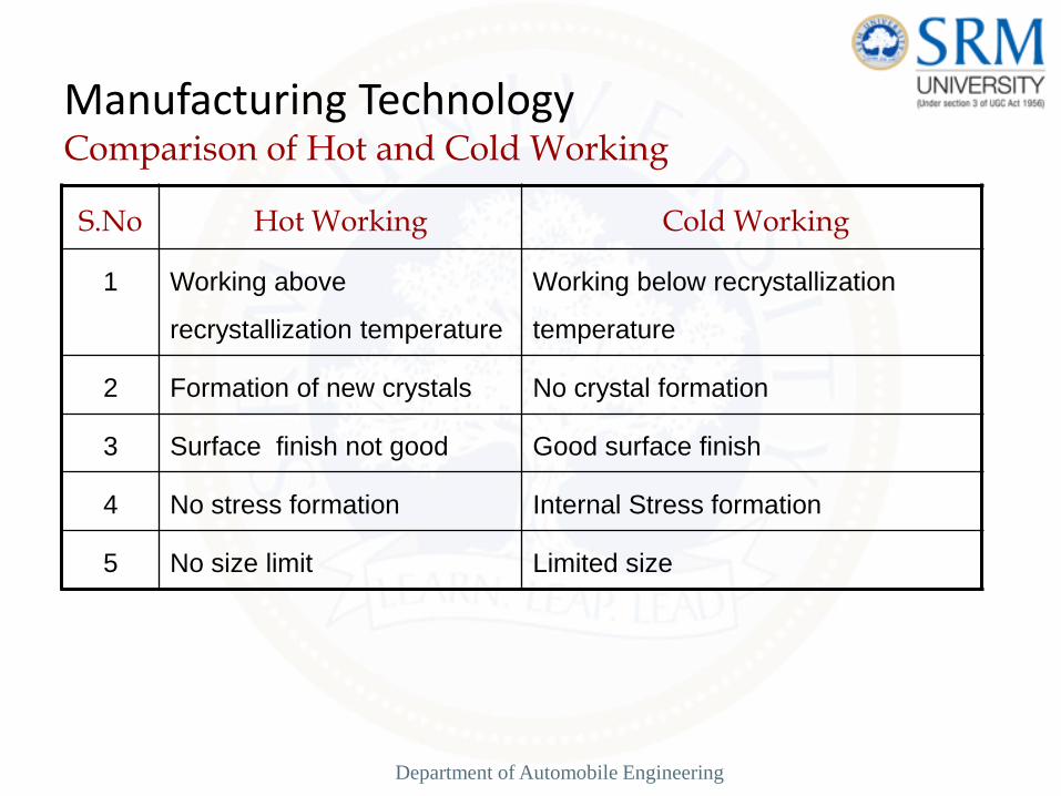
Manufacturing Technology Comparison of Hot and Cold Working
S.No Hot Working Cold Working
1 Working above
recrystallization temperature
Working below recrystallization
temperature
2 Formation of new crystals No crystal formation
3 Surface finish not good Good surface finish
4 No stress formation Internal Stress formation
5 No size limit Limited size
Department of Automobile Engineering
Forging
Forging is a process in which the work piece is shaped by
compressive forces applied through various dies and tools. It is one
of the oldest metalworking operations. Most forgings require a set
of dies and a press or a forging hammer.
Unlike rolling operations, which generally produce continuous
plates, sheets, strip, or various structural cross-sections, forging
operations produce discrete parts.
Typical forged products are bolts and rivets, connecting rods, shafts
for turbines, gears, hand tools, and structural components for
machinery, aircraft, railroads and a variety of other transportation
equipment.
Manufacturing Technology
Department of Automobile Engineering

Manufacturing Technology Forging
Department of Automobile Engineering

Manufacturing Technology Forging Methods
Open-Die Forging
• Compression of work part between two flat dies
• Deformation operation reduces height and increases diameter of
work
• Common names include upsetting or upset forging
Department of Automobile Engineering
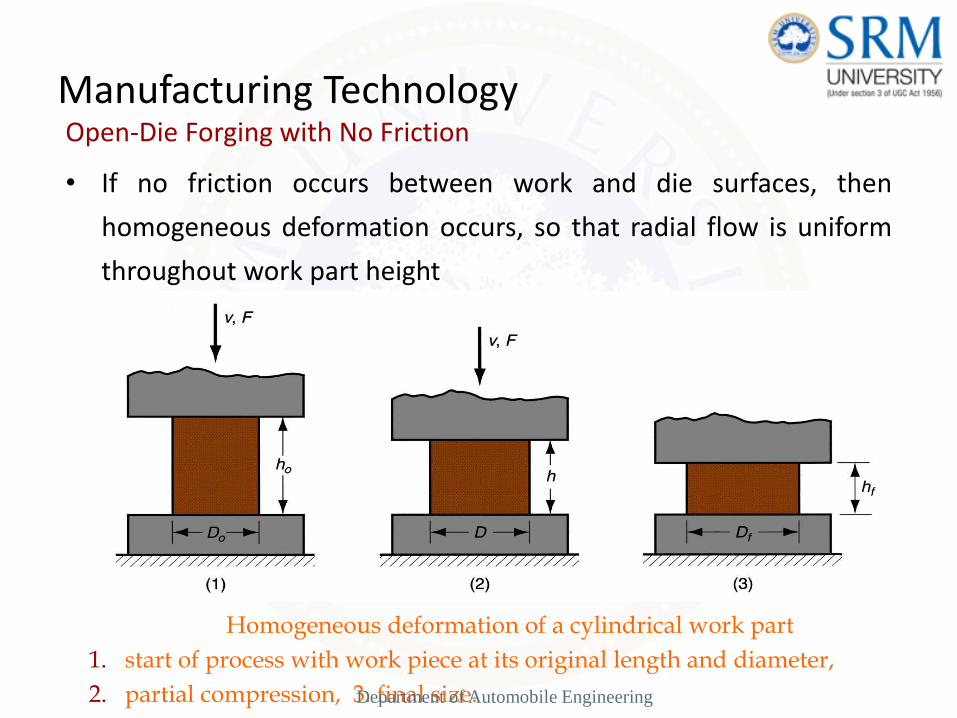
Manufacturing Technology Open-Die Forging with No Friction
• If no friction occurs between work and die surfaces, then
homogeneous deformation occurs, so that radial flow is uniform
throughout work part height
Homogeneous deformation of a cylindrical work part
1. start of process with work piece at its original length and diameter,
2. partial compression, 3. final size. Department of Automobile Engineering
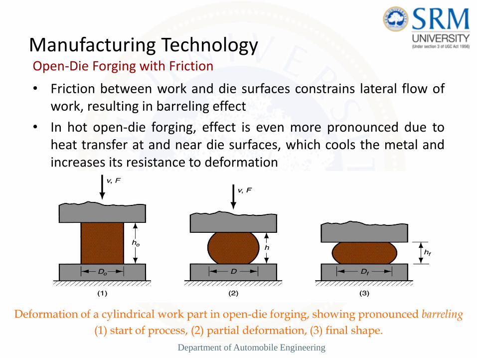
Manufacturing Technology Open-Die Forging with Friction
• Friction between work and die surfaces constrains lateral flow of work, resulting in barreling effect
• In hot open-die forging, effect is even more pronounced due to heat transfer at and near die surfaces, which cools the metal and increases its resistance to deformation
Deformation of a cylindrical work part in open-die forging, showing pronounced barreling
(1) start of process, (2) partial deformation, (3) final shape.
Department of Automobile Engineering

Manufacturing Technology Impression-Die Forging
• Compression of work part by dies with inverse of desired part shape
• Flash is formed by metal that flows beyond die cavity into small gap between die plates
• Flash serves an important function:
– As flash forms, friction resists continued metal flow into gap, constraining material to fill die cavity
– In hot forging, metal flow is further restricted by cooling against die plates
Department of Automobile Engineering

Manufacturing Technology Impression-Die Forging
(1) just prior to initial contact with raw work piece, (2) partial compression, and (3) final die closure, causing flash to form in gap between die plates.
Department of Automobile Engineering

Manufacturing Technology
Trimming After Impression-Die Forging
• Trimming operation (shearing process) to remove the flash after impression-die forging.
Department of Automobile Engineering

• Advantages of impression-die forging compared to
machining from solid stock:
– Higher production rates
– Less waste of metal
– Greater strength
– Favorable grain orientation in the metal
• Limitations:
– Not capable of close tolerances
– Machining often required to achieve accuracies and
features needed
Manufacturing Technology
Department of Automobile Engineering

Flash less Forging
• Compression of work in punch and die tooling whose cavity does not allow for flash
• Starting work part volume must equal die cavity volume within very close tolerance
• Process control more demanding than impression-die forging
• Best suited to part geometries that are simple and symmetrical
• Often classified as a precision forging process
Manufacturing Technology
Department of Automobile Engineering
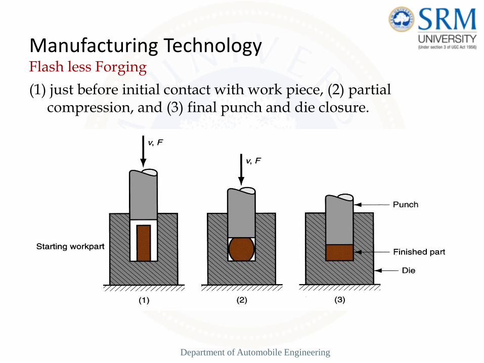
Manufacturing Technology Flash less Forging
(1) just before initial contact with work piece, (2) partial compression, and (3) final punch and die closure.
Department of Automobile Engineering

Forging Hammers (Drop Hammers)
• Apply impact load against work part
Two types
– Gravity drop hammers - impact energy from falling
weight of a heavy ram
– Power drop hammers - accelerate the ram by
pressurized air or steam
• Disadvantage: impact energy transmitted through anvil
into floor of building
• Commonly used for impression-die forging
Manufacturing Technology
Department of Automobile Engineering

Manufacturing Technology Drop Hammer Details
Diagram showing details of a drop hammer for
impression-die forging. Department of Automobile Engineering

Forging Presses
• Apply gradual pressure to accomplish compression operation
Types
– Mechanical press - converts rotation of drive motor into linear motion of ram
– Hydraulic press - hydraulic piston actuates ram
– Screw press - screw mechanism drives ram
Manufacturing Technology
Department of Automobile Engineering
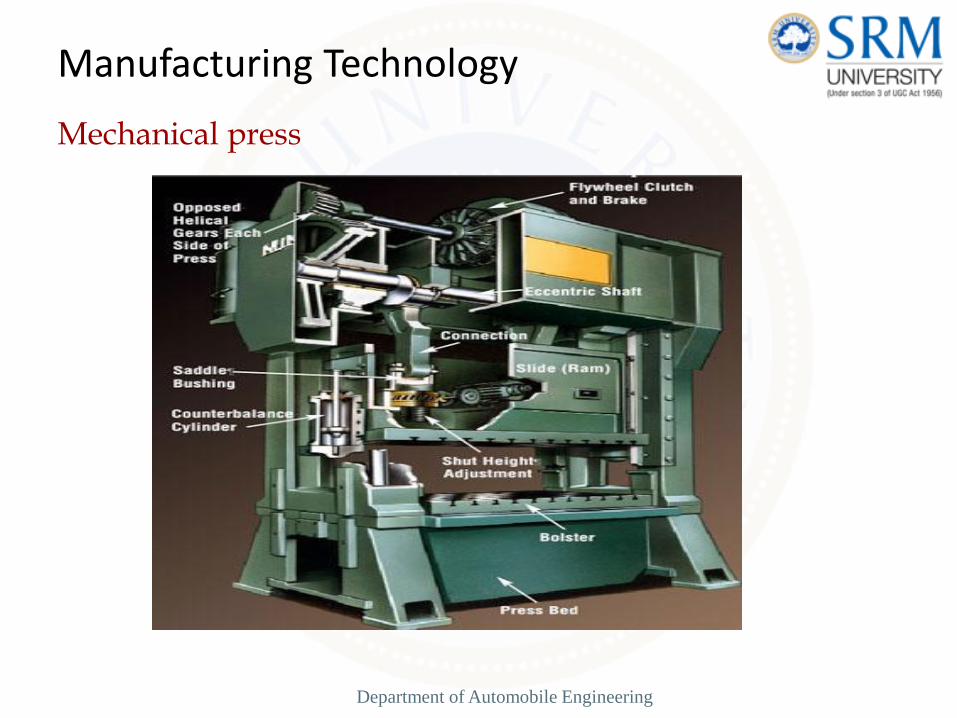
Mechanical press
Manufacturing Technology
Department of Automobile Engineering
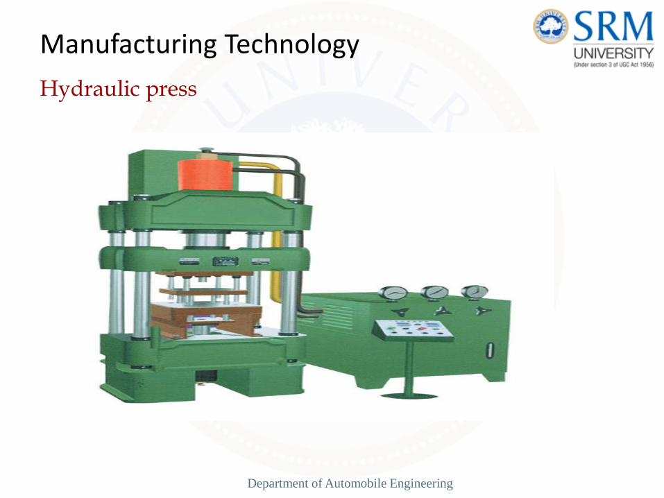
Hydraulic press
Manufacturing Technology
Department of Automobile Engineering

Upsetting and Heading
• Forging process used to form heads on nails, bolts, and similar hardware products
• More parts produced by upsetting than any other forging operation
• Performed cold, warm, or hot on machines called headers or formers
• Wire or bar stock is fed into machine, end is headed, then piece is cut to length
• For bolts and screws, thread rolling is then used to form threads
Manufacturing Technology
Department of Automobile Engineering
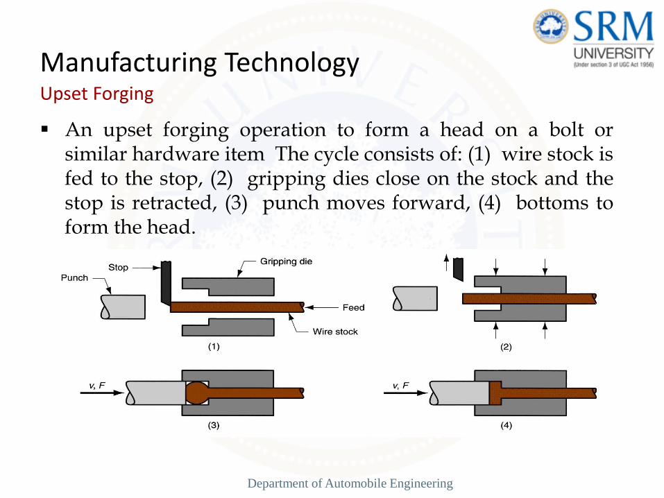
Manufacturing Technology Upset Forging
An upset forging operation to form a head on a bolt or similar hardware item The cycle consists of: (1) wire stock is fed to the stop, (2) gripping dies close on the stock and the stop is retracted, (3) punch moves forward, (4) bottoms to form the head.
Department of Automobile Engineering

Manufacturing Technology
Heading
Examples of heading (upset forging) operations: (a) heading a nail using open dies, (b) round head formed by punch, (c) and (d) two common head styles for screws formed by die, (e) carriage bolt head formed by punch and die.
Department of Automobile Engineering

Forging Defects
• Fracture
– Exhausted ductility
– Inter-granular fracture
• Barreling - Friction
Solution
– limited deformation per step
– Process anneal between steps
Manufacturing Technology
Department of Automobile Engineering

Manufacturing Technology
Rolling
• Deformation process in which work thickness is reduced by compressive forces exerted by two opposing rolls
The rolling process (specifically, flat rolling) Department of Automobile Engineering

Rolling • The initial breaking down of an ingot or of a continuously cast slab is
done by hot rolling. A cast structure includes coarse and non-uniform grains. This structure is usually brittle and may contain porosities.
• Hot rolling converts the cast structure to a wrought structure. This structure has finer grains and enhanced ductility, both resulting from the breaking up of brittle grain boundaries and the closing up of internal defects, especially porosity.
• The product of the first hot rolling operation is called bloom or slab. A bloom usually has a square cross-section, at least 150 mm (6in) on the side; a slab is usually rectangular in cross section. Blooms are processed further, by shape rolling, into structural shapes, such as I-beams and railroad rails. Slabs are rolled into planes and sheet.
• Billets are usually square, with a cross-sectional area smaller than blooms; they are later rolled into various shapes, such as round rods and bars, by the use of shaped rolls. Hot-rolled round rods are used as the starting material for rod and wire drawing. They are called wire rods.
Manufacturing Technology
Department of Automobile Engineering
Rolling
• One of the primary first process to convert raw material into finished
product.
• Starting material (Ingots) are rolled into blooms, billets, or slabs by
feeding material through successive pairs of rolls.
• Bloom - square or rectangular cross section with a thickness
greater than 6” and a width not greater than 2x’s the
thickness
• Billets - square or circular cross section - - smaller than a
bloom
• Slabs - rectangular in shape (width is greater than 2x’s the
thickness), slabs are rolled into plate, sheet, and strips.
Manufacturing Technology
Department of Automobile Engineering

Rolling
Manufacturing Technology
Department of Automobile Engineering

Manufacturing Technology Rolled Products Made of Steel
Some of the steel products made in a rolling mill
.
Department of Automobile Engineering

Rotating rolls perform two main functions:
• Pull the work into the gap between them by friction
between work part and rolls
• Simultaneously squeeze the work to reduce its cross
section
Manufacturing Technology
Department of Automobile Engineering

Types of Rolling
• Based on work piece geometry :
– Flat rolling - used to reduce thickness of a rectangular
cross section
– Shape rolling - square cross section is formed into a shape
such as an I-beam
• Based on work temperature :
– Hot Rolling – most common due to the large amount of
deformation required
– Cold rolling – produces finished sheet and plate stock
Manufacturing Technology
Department of Automobile Engineering

Manufacturing Technology Flat Rolling
Heated metal is passed between rotating rolls to reduce the cross-section.
Side view of flat rolling, indicating before and after thicknesses, work
velocities, angle of contact with rolls, and other features.
Department of Automobile Engineering

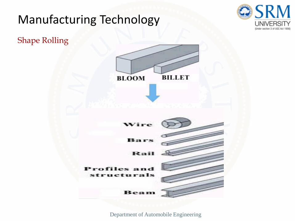
Shape Rolling
• Work is deformed into a contoured cross section rather than
flat (rectangular)
• Accomplished by passing work through rolls that have the
reverse of desired shape
• Products include:
– Construction shapes such as I-beams, L-beams, and
U-channels
– Rails for railroad tracks
– Round and square bars and rods
Manufacturing Technology
Department of Automobile Engineering
Shape Rolling
Manufacturing Technology
Department of Automobile Engineering
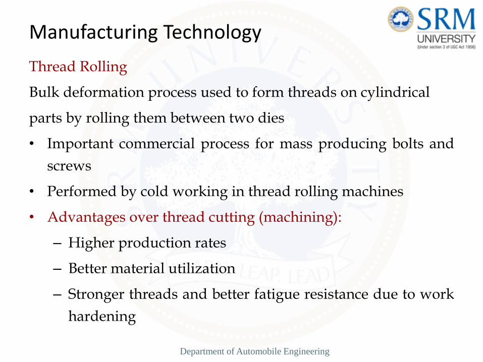
Thread Rolling
Bulk deformation process used to form threads on cylindrical
parts by rolling them between two dies
• Important commercial process for mass producing bolts and
screws
• Performed by cold working in thread rolling machines
• Advantages over thread cutting (machining):
– Higher production rates
– Better material utilization
– Stronger threads and better fatigue resistance due to work
hardening
Manufacturing Technology
Department of Automobile Engineering
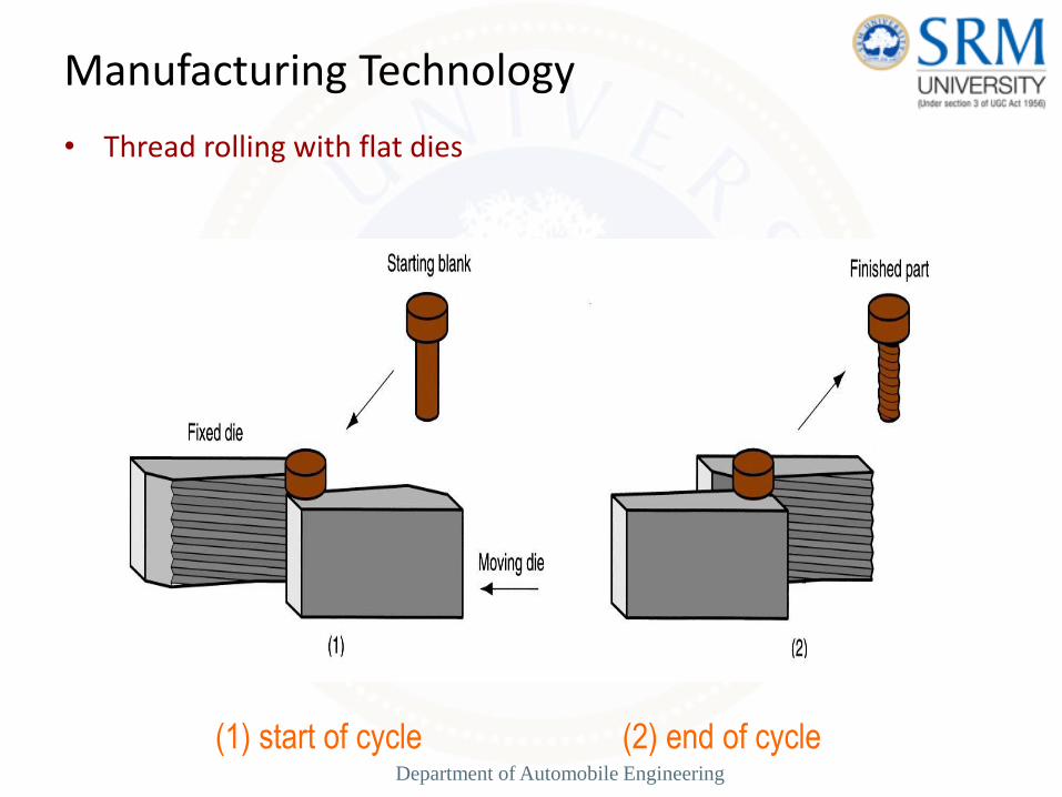
• Thread rolling with flat dies
Manufacturing Technology
(1) start of cycle (2) end of cycle Department of Automobile Engineering
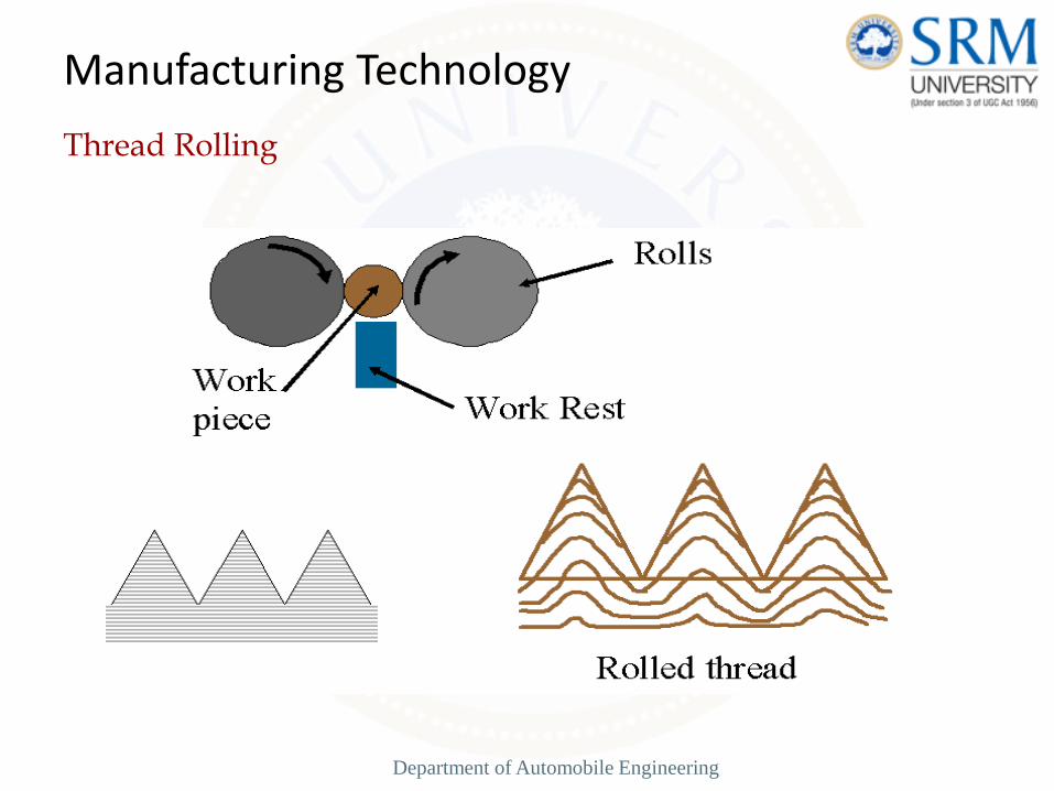
Thread Rolling
Manufacturing Technology
Department of Automobile Engineering
Rolling Mills
• Equipment is massive and expensive
• Rolling mill configurations:
– Two-high – two opposing rolls
– Three-high – work passes through rolls in both directions
– Four-high – backing rolls support smaller work rolls
– Cluster mill – multiple backing rolls on smaller rolls
– Tandem rolling mill – sequence of two-high mills
Manufacturing Technology
Department of Automobile Engineering

Two-High Rolling.
Manufacturing Technology
a -2-high rolling mill. Department of Automobile Engineering
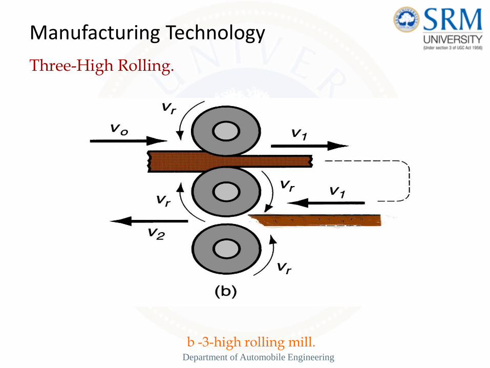
Three-High Rolling.
Manufacturing Technology
b -3-high rolling mill. Department of Automobile Engineering

Four-High Rolling.
Manufacturing Technology
b -4-high rolling mill. Department of Automobile Engineering

Cluster Mill
Manufacturing Technology
d -Cluster mill. Department of Automobile Engineering
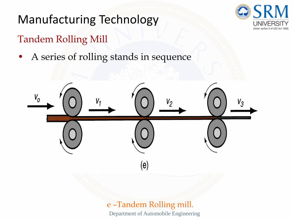
Tandem Rolling Mill
• A series of rolling stands in sequence
Manufacturing Technology
e –Tandem Rolling mill. Department of Automobile Engineering
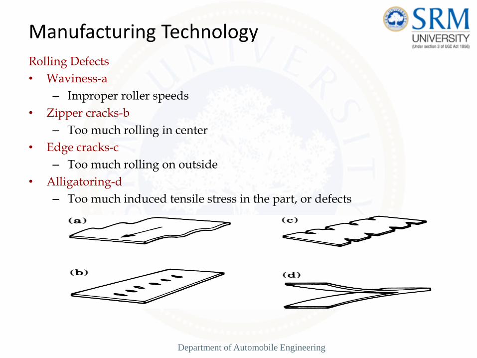
Rolling Defects
• Waviness-a
– Improper roller speeds
• Zipper cracks-b
– Too much rolling in center
• Edge cracks-c
– Too much rolling on outside
• Alligatoring-d
– Too much induced tensile stress in the part, or defects
Manufacturing Technology
Department of Automobile Engineering

DEFECTS IN FORGED PARTS
Defects commonly found in forged parts that have been subjected to plastic deformation are as follows.
(i) Defects resulting from the melting practice such as dirt, slag and blow holes.
(ii) Ingot defects such as pikes, cracks scabs, poor surface and segregation.
(iii) Defect due to faulty forging design.
(iv) Defects of mismatched forging because of improper placement of the metal in the die.
(v) Defects due to faulty design drop forging die.
(vi) Defects resulting from improper forging such as seams cracks laps. etc.
(vii) Defects resulting from improper heating and cooling of the forging part such as burnt metal and decarburized steel.
Some well identified common forging defects along with their reason are given as under.
Department of Automobile Engineering
1. Mismatched forging
Reasons
Due to non alignment of proper die halves.
2. Brunt and overheated metal
Reasons
This is caused by improper heating the metal at high temperature or for a long time.
3. Fibred flow lines discontinued
Reasons
This will occur because of very rapid plastic flow of metal.
4. Scale pits
Reason
These are formed by squeezing of scale into the metal surface during forging.
5. Oversize components
Reasons
Due to worn out dies, incorrect dies, misalignment of die halves.
Department of Automobile Engineering


![[XLS] · Web viewComputer Integrated Manufacturing (PLTW) ADMF 116 Automation & Robotics in Manufacturing Civil Enginnering & Architecture (PLTW) Marketing 4250 Cardinal Ritter High](https://static.fdocuments.in/doc/165x107/5a9f9ccf7f8b9a89178cf32f/xls-viewcomputer-integrated-manufacturing-pltw-admf-116-automation-robotics.jpg)


