Manufacturing Inc. Installation, Operation, and ... Operation, and Maintenance ENG00018621 Rev A ......
16
Installation, Operation, and Maintenance ENG00018621 Rev A Air Cooled Fluid Coolers When you want Quality, specify COLMAC! Manufacturing Inc. COLMAC COIL Contents 1. SAFETY INSTRUCTIONS .......................................................................................................... 1 2. MODEL NOMECLATURE........................................................................................................... 3 3. GENERAL DESCRIPTION ......................................................................................................... 4 4. INSTALLATION .......................................................................................................................... 4 5. OPERATION ............................................................................................................................... 7 6. MAINTENANCE .......................................................................................................................... 8
Transcript of Manufacturing Inc. Installation, Operation, and ... Operation, and Maintenance ENG00018621 Rev A ......

Installation, Operation, and Maintenance ENG00018621 Rev A
Air Cooled Fluid Coolers
When you want Quality, specify COLMAC!
Manufacturing Inc.
COLMACCOIL
Contents 1. SAFETY INSTRUCTIONS .......................................................................................................... 1
2. MODEL NOMECLATURE ........................................................................................................... 3
3. GENERAL DESCRIPTION ......................................................................................................... 4
4. INSTALLATION .......................................................................................................................... 4
5. OPERATION ............................................................................................................................... 7
6. MAINTENANCE .......................................................................................................................... 8


1 ENG00018621 Rev A, 10-6-15
COLMAC
1. SAFETY INSTRUCTIONS To avoid serious personal injury, accidental death, or major property damage, read and follow all safety instructions in the manual and on the equipment. Maintain all safety labels in good condition. If necessary, replace labels using the provided part numbers.
This is the safety alert symbol. It is used to alert you to potential personal injury hazards. Obey all safety messages that follow this symbol to avoid possible injury or death.
DANGER indicates a hazardous situation which, if not avoided, will result in death or serious injury.
WARNING indicates a hazardous situation which, if not avoided, could result in death or serious injury.
CAUTION indicates a hazardous situation which, if not avoided, could result in minor or moderate injury.
NOTICE indicates instructions that pertain to safe equipment operation. Failure to follow these instructions could result in equipment damage.
PUR00019535
PUR00019560
PUR00019561

2 ENG00018621 Rev A, 10-6-15
COLMAC
PUR00019536
PUR00019634
3 ENG00018621 Rev A, 10-6-15
COLMAC
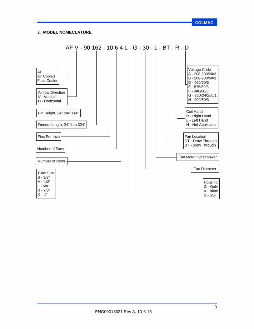
2. MODEL NOMECLATURE
AF V - 90 162 - 10 6 4 L - G - 30 - 1 - BT - R - D
AF Air Cooled Fluid Cooler
Airflow Direction V - Vertical H - Horizontal
Fin Height, 24” thru 114”
Finned Length, 24” thru 324”
Fins Per Inch
Number of Fans
Number of Rows
Tube Size S - 3/8” M - 1/2" L - 5/8” R - 7/8” X – 1"
Voltage Code A - 208-230/60/3B - 208-230/60/3D - 460/60/3 E - 575/60/3 F - 380/60/3 G - 220-240/50/1H - 200/50/3
Coil Hand R - Right Hand L - Left Hand N - Not Applicable
Fan Location DT - Draw ThroughBT - Blow Through
Fan Motor Horsepower
Fan Diameter
HousingG - GalvA - AlumS - SST

4 ENG00018621 Rev A, 10-6-15
COLMAC
3. GENERAL DESCRIPTION
3.1. Colmac Fluid Coolers are multiple row compact finned tube coolers with direct drive fans. The fluid circulates in multiple passes through the tubes and cooling air flows over the exterior finned surface. They are designed to provide cooling of Water, Ethylene Glycol/Water, and Propylene Glycol/Water solutions in a variety of closed loop applications. Closed loop cooling eliminates the cost of fluid treatment usually associated with the use of cooling towers. The compact plate fin heat transfer surface provides a compact and efficient air cooled fluid cooler.
3.2. The fan motors are heavy-duty, rigid foot mounted, direct drive, totally enclosed fan
motors with moisture protected rain shields (slingers) suitable for an industrial environment.
3.3. The published fan sound level is based on free field conditions with no sound reflecting
surfaces. If the cooler sound level is important, avoid installing the cooler within 30 feet of any large reflecting surface such as a building or wall. If this is not possible, the installed sound level must be recalculated for the actual site condition.
4. INSTALLATION
4.1. Inspection
4.1.1. Damage or Shortage – Upon receipt of equipment, inspect for shortages and damage. Any shortage or damage found during initial inspection should be noted on delivery receipt. This action notifies the carrier that you intend to file a claim. Any damaged equipment is the responsibility of the carrier, and should not be returned to Colmac Coil without prior notification. If any shortage or damage is discovered after unpacking the unit, call the deliverer for a concealed damage or shortage inspection. The inspector will need related paperwork, delivery receipt, and any information indicating his liability for the damage.
4.1.2. Specified Equipment – Check unit nameplate for: Electrical specifications to
ensure compatibility with electrical power supply. Check model nomenclature and other information to ensure that the equipment matches the original order.
4.2. Mounting & Rigging
4.2.1. NOTICE: In no circumstances should coil headers or return bends be used
in lifting or moving condensers.
4.2.2. NOTICE: Use shipping container, or use hangers to lift unit into mounting position.
4.2.3. The fluid coolers are fitted with lifting eyes on the top face of the cooler. Use lifting
beams as illustrated in Figures 1 and 2.
4.2.4. All lifting must be done perpendicular to top of coil face with lifting straps attached to the lifting brackets in a vertical configuration as illustrated in Figures 1 and 2.
4.2.5. NOTICE: Do not lift units with lifting straps attached to the lifting brackets in
an A-frame configuration.
4.3. Mechanical
4.3.1. Level the fluid cooler and install steel shims to fill any gaps under the support feet.
5 ENG00018621 Rev A, 10-6-15
COLMAC
4.3.2. NOTICE: The fluid inlet must always be connected to the header on the air
outlet side for counterflow operation.
4.3.3. After the flange bolts are installed, tighten snug but do not torque. Next install the mechanical anchors at all support lets and tighten down and then tighten the flange bolts.
4.3.4. NOTICE: Do not force flanges to come together. If flanges are not parallel,
they will require adjustments with either application of heat to the nozzle or by removal and re-welding. Contact Colmac for instructions.
4.4. Electrical
4.4.1. Each Colmac AFV/AFH fluid cooler is factory wired for single-point connections in
the field to the weatherproof terminal box on each cooler or to each individual motor at each fan bay depending on customer specification. Fan motors greater than 1 Hp do not have internal thermal overload protection controls; they must be provided by others. Fan Motors 1 Hp and smaller do have internal thermal overload protection. Standard construction does not include fan cycling and fused disconnects which must be supplied by others. Individual motor protection and fan cycling controls are available as optional extras.
4.4.2. All field wiring must comply with National Electrical Code and all other state and
local regulations. This includes providing proper and safe motor protection, fusing, disconnects, and other basic equipment.
4.4.3. Check that the supply voltage matches the motor rated voltage. After the motors
are connected, jog them to check for fan clearance and for proper fan rotation. Rotation can be reversed by swapping two of the three incoming line conductors on a three phase system. Operate all the fan motors for several hours to allow the motors to dry.
4.4.4. For fluid coolers equipped with FC (fan cycling) controls, refer to the wiring diagram
included with the unit for control and connection details.
4.5. Location
4.5.1. Colmac fluid coolers have been designed primarily for outdoor installations. When locating the unit on a roof, it must be mounted on support beams which span load-bearing walls. Failure to do so may lead to excessive vibration on a resilient roof and possible damage to the unit. Refer to unit weights indicated on the submittal drawing or shipping documents and to the refrigerant line weights referenced below.
4.5.2. Locate the fluid cooler no closer than the unit’s width from a wall or other
obstruction. When two or more units occupy the same area, space them apart by a minimum distance of one unit’s width to allow free air circulation around the coils.
4.5.3. The fluid cooler must be installed level and be securely anchored to the building
structure or concrete pad.

6 ENG00018621 Rev A, 10-6-15
COLMAC
Table 1
Weight of Ethylene Glycol in Type L Copper Lines
Line Size O.D.
Pounds per 100 Lineal Ft, Ethelene Glycol
0% Glycol 20% Glycol 40% Glycol
100°F / 135°F 100°F / 135°F 100°F / 135°F
5/8 7/8
1 1/8 1 3/8 1 5/8 2 1/8 2 5/8 3 1/8 3 5/8 4 1/8
10.0 / 10.0 20.3 / 20.1 35.5 / 35.2 54.1 / 53.6 76.5 / 75.9
133.1 / 132.0 205.3 / 203.6 293.1 / 290.6 396.4 / 393.1 515.3 / 511.0
10.3 / 10.2 20.8 / 20.7 36.5 /36.1 55.5 / 55.0 78.6 / 77.9
136.8 / 135.5 210.9 / 209.0 301.0 / 298.3 407.2 / 403.5 529.3 / 524.5
10.6 / 10.5 21.4 / 21.2 37.1 / 36.7 57.0 / 56.5 80.7 / 79.9
140.4 / 139.0 216.5 / 214.4 309.1 / 306.0 418.0 / 413.9 543.4 / 538.1
Table 2
Weight of Propylene Glycol in Type L Copper Lines
Line Size O.D.
Pounds per 100 Lineal Ft, Propylene Glycol
0% Glycol 20% Glycol 40% Glycol
100°F / 135°F 100°F / 135°F 100°F / 135°F
5/8 7/8
1 1/8 1 3/8 1 5/8 2 1/8 2 5/8 3 1/8 3 5/8 4 1/8
10.0 / 9.9 20.3 / 20.1 35.5 / 35.2 54.1 / 53.6 76.5 / 75.9
133.1 / 132.0 205.3 / 203.6 293.1 / 290.6 396.4 / 393.1 515.3 / 511.0
10.2 / 10.1 20.7 / 20.5 36.1 /35.8 55.1 / 54.5 77.9 / 77.1
135.6 / 134.2 209.1 / 207.0 298.4 / 295.4 403.6 / 399.5 524.7 / 519.4
10.4 / 10.3 21.0 / 20.7 36.7 / 36.3 55.9 / 55.2 79.1 / 78.2
137.6 / 136.0 212.2 / 209.7 302.9 / 299.3 409.7 / 404.9 532.6 / 526.3
4.6. Filling
4.6.1. Clean water is suitable for flushing and testing in warm weather, but when the temperature is below freezing, a glycol/water solution is required.
4.6.2. All system piping must be flushed before connecting it to the fluid cooler.
4.6.3. NOTICE: Do not flush the system through the fluid cooler as dirt and
welding debris from the piping can cause fowling of the internal surfaces of the tubing and potentially block the tubes.
4.6.4. Vent all air from the piping and cooler during filling.

7 ENG00018621 Rev A, 10-6-15
COLMAC
4.6.5. When the air is all vented, pressurize the system, and check all of the flange joints
for leaks, and retighten flange bolts where necessary.
4.6.6. After testing, drain the flushing fluid and replace with clean demineralized water and glycol solution of the specified ratio prior to operation.
4.7. Storage
4.7.1. If the fluid coolers are to be stored or not operated for an extended period of time,
the fan motors may ingress moisture if they are not protected or operated regularly. In severe cases, the moisture will reduce the insulation level of the windings or cause rusting of the bearings necessitating removal for repairs at a motor repair facility. This is a common problem with large generating installations when the coolers are often ready but commissioning of the main turbine-generator is delayed for several months.
4.7.2. The simplest remedy for installed coolers is to operate the fan motors for a few
hours every week during the downtime period until regular operation resumes. The fan motors on stored coolers must be protected from the elements by covering them with waterproof tarps.
5. OPERATION
5.1. Before Startup
5.1.1. Make sure unit voltage agrees with supply voltage.
5.1.2. Make sure system is wired correctly and in accordance with the guidelines laid out in this IOM, as well as local and national standards that may apply.
5.1.3. Check torque on all electrical connections.
5.1.4. Make sure all piping is done completely and in accordance with the guidelines laid
out in this IOM, as well as in accordance with standard good practice.
5.1.5. Make sure unit is mounted securely using all hangers, and is level.
5.1.6. Make sure that all fan set screws are tight.
5.2. After Startup
5.2.1. Check fan rotation of all fans to make sure air is moving in proper direction.
5.3. Fan Cycling Setup Checklist
5.3.1. Heating/Cooling Mode Adjustment: As shipped from the factory, the fan cycling controller is set up for cooling mode.
5.3.2. Setpoint Adjustment: Set point is defined as the temperature setting at which the
temperature controller output relay will de-energize.
5.3.3. Differential Adjustment: Differential is defined as the change in sensor temperature between energization and de-energization of the relay. In cooling mode, the temperature controller will energize the output relay at a temperature equal to the

8 ENG00018621 Rev A, 10-6-15
COLMAC
setpoint plus the differential. The temperature controller will de-energize the output relay at a temperature equal to the setpoint.
5.3.4. Offset: On temperature controllers with offset functionality, the offset adjustment sets the temperature offset from the control module setpoint, at which the stage module’s output relay will de-energize.
5.3.5. Temperature Sensor
For sensing fluid temperature: Insert sensor into sensor well in outlet header
utilizing thermal paste to ensure good heat transfer.
For sensing ambient temperature: Attach sensor to unit leg away from fan induced air flow and out of direct sunlight.
5.3.6. Control Settings
Master Setpoint & Differential Table
(Values supplied by sales and/or engineering) Type F.C Controls
Setpoint 1 Differential 1
Bulb Location
Cond. Leaving Fluid Temp.
Ambient Air Temp.
Stage Differential & Offset Table (Values supplied by sales and/or engineering)
Type F.C Controls
Offset 1 Differential 1
Offset 2 Differential 2
Offset 3 Differential 3
Offset 4 Differential 4
Offset 5 Differential 5
Offset 6 Differential 6
Offset 7 Differential 7
Offset 8 Differential 8
Offset 9 Differential 9 6. MAINTENANCE
6.1. The direct Drive fan motors are provided with double sealed shaft bearings. Periodic lubrication is not required.
6.2. Check the fan blades annually and remove any accumulations of dirt.
6.3. Cleaning inside: When the glycol/water solution is maintained in its original condition,
the inside of the tubes will not require regular cleaning. If the glycol/water solution is allowed to deteriorate, the inside of the tubes may become corroded or fouled and

9 ENG00018621 Rev A, 10-6-15
COLMAC
require cleaning. Disconnect the cooler from the pipe connections and fill with chemical cleaners suitable for copper tubes. Drain and flush with clean water after cleaning.
6.4. Cleaning Outside: Remove any debris that collects on the air inlet side of the finned
tubes as this will reduce the airflow. The debris can often be removed by shutting off the fans and blowing air or a water spray in the reverse direction. A soft bristled brush with a water-detergent solution may be required to remove oily deposits followed by rinsing with clean water. Straighten any fins that may have bent during cleaning.
6.5. Replacement Parts
6.5.1. Replacement parts which are covered under the conditions of Colmac Coil’s
warranty (see Limited Warranty) will be reimbursed at the part cost only. For replacement parts, warranted or otherwise, contact Colmac Coil directly. When contacting Colmac Coil with the explanation of failure, have the complete model number, serial number, date of installation, and date of failure at hand.

10 ENG00018621 Rev A, 10-6-15
COLMAC
FIGURE 1
Vertical Fluid Cooler Rigging

11 ENG00018621 Rev A, 10-6-15
COLMAC
FIGURE 2
Horizontal Fluid Cooler Rigging

12 ENG00018621 Rev A, 10-6-15
COLMAC

13 ENG00018621 Rev A, 10-6-15
COLMAC

Manufacturing Inc.
COLMACCOIL
Colmac reserves the right to change product design and specifications without notice.
For more information on Colmac products call us at 1-800-845-6778 or visit us online at:
WWW.COLMACCOIL.COM