DIGITAL MULTIFUNCTIONAL SYSTEM Software Setup GuideSSoftware Setup
Manufacturer HSM Installation and Setup
User Guide
For Libero SoC v11.7 SP1
Revision 1 2
Table of Contents
Introduction . . . . . . . . . . . . . . . . . . . . . . . . . . . . . . . . . . . . . . . . . . . . . . . . . . . . . . . . . . . . . . . . . . . . . . . . . 3Referenced Documents . . . . . . . . . . . . . . . . . . . . . . . . . . . . . . . . . . . . . . . . . . . . . . . . . . . . . . . . . . . . . . . . . . . . . . 3
1 M-HSM Server . . . . . . . . . . . . . . . . . . . . . . . . . . . . . . . . . . . . . . . . . . . . . . . . . . . . . . . . . . . . . . . . . . . . 4Server Components . . . . . . . . . . . . . . . . . . . . . . . . . . . . . . . . . . . . . . . . . . . . . . . . . . . . . . . . . . . . . . . . . . . . . . . . . 4
Security World and HSM Modules . . . . . . . . . . . . . . . . . . . . . . . . . . . . . . . . . . . . . . . . . . . . . . . . . . . . . . . . . . . . . . 4
System Requirements . . . . . . . . . . . . . . . . . . . . . . . . . . . . . . . . . . . . . . . . . . . . . . . . . . . . . . . . . . . . . . . . . . . . . . . 7
2 M-HSM Installation and Setup Scenarios . . . . . . . . . . . . . . . . . . . . . . . . . . . . . . . . . . . . . . . . . . . . . . . 9
3 Initial M-HSM Server Installation and Setup . . . . . . . . . . . . . . . . . . . . . . . . . . . . . . . . . . . . . . . . . . . . 10Software Installation . . . . . . . . . . . . . . . . . . . . . . . . . . . . . . . . . . . . . . . . . . . . . . . . . . . . . . . . . . . . . . . . . . . . . . . . 10
M-HSM Server Software Installation . . . . . . . . . . . . . . . . . . . . . . . . . . . . . . . . . . . . . . . . . . . . . . . . . . . . . . . . . . . 10
HSM Hardware Module Installation . . . . . . . . . . . . . . . . . . . . . . . . . . . . . . . . . . . . . . . . . . . . . . . . . . . . . . . . . . . . 10
M-HSM Server Provisioning . . . . . . . . . . . . . . . . . . . . . . . . . . . . . . . . . . . . . . . . . . . . . . . . . . . . . . . . . . . . . . . . . . 14
FTP Server Setup . . . . . . . . . . . . . . . . . . . . . . . . . . . . . . . . . . . . . . . . . . . . . . . . . . . . . . . . . . . . . . . . . . . . . . . . . 22
4 M-HSM Reconfiguration and Post-Installation Actions . . . . . . . . . . . . . . . . . . . . . . . . . . . . . . . . . . . . 31HSM Module Replacement . . . . . . . . . . . . . . . . . . . . . . . . . . . . . . . . . . . . . . . . . . . . . . . . . . . . . . . . . . . . . . . . . . 31
Import the Public Key of the U-HSM . . . . . . . . . . . . . . . . . . . . . . . . . . . . . . . . . . . . . . . . . . . . . . . . . . . . . . . . . . . 32
Export the Public Key for Sending to an M-HSM . . . . . . . . . . . . . . . . . . . . . . . . . . . . . . . . . . . . . . . . . . . . . . . . . . 32
Import the New DFK DB and Manufacturing Keys from the U-HSM . . . . . . . . . . . . . . . . . . . . . . . . . . . . . . . . . . . . . . . . . . . . . . . . . . . . . . . . . . . . . . . . . . . . . . . . . . . . . . . 32
Upgrade the HSM Module Firmware . . . . . . . . . . . . . . . . . . . . . . . . . . . . . . . . . . . . . . . . . . . . . . . . . . . . . . . . . . . 32
5 M-HSM Server Replication . . . . . . . . . . . . . . . . . . . . . . . . . . . . . . . . . . . . . . . . . . . . . . . . . . . . . . . . . 33Install the Software . . . . . . . . . . . . . . . . . . . . . . . . . . . . . . . . . . . . . . . . . . . . . . . . . . . . . . . . . . . . . . . . . . . . . . . . 33
Copy Over the Security World . . . . . . . . . . . . . . . . . . . . . . . . . . . . . . . . . . . . . . . . . . . . . . . . . . . . . . . . . . . . . . . . 33
Copy Over the M-HSM Server . . . . . . . . . . . . . . . . . . . . . . . . . . . . . . . . . . . . . . . . . . . . . . . . . . . . . . . . . . . . . . . . 33
Install a New HSM Module . . . . . . . . . . . . . . . . . . . . . . . . . . . . . . . . . . . . . . . . . . . . . . . . . . . . . . . . . . . . . . . . . . . 33
Start the M-HSM Server . . . . . . . . . . . . . . . . . . . . . . . . . . . . . . . . . . . . . . . . . . . . . . . . . . . . . . . . . . . . . . . . . . . . . 33
Set Up the FTP Server . . . . . . . . . . . . . . . . . . . . . . . . . . . . . . . . . . . . . . . . . . . . . . . . . . . . . . . . . . . . . . . . . . . . . . 33
A Product Support . . . . . . . . . . . . . . . . . . . . . . . . . . . . . . . . . . . . . . . . . . . . . . . . . . . . . . . . . . . . . . . . . 34Customer Service . . . . . . . . . . . . . . . . . . . . . . . . . . . . . . . . . . . . . . . . . . . . . . . . . . . . . . . . . . . . . . . . . . . . . . . . . 34
Customer Technical Support Center . . . . . . . . . . . . . . . . . . . . . . . . . . . . . . . . . . . . . . . . . . . . . . . . . . . . . . . . . . . 34
Technical Support . . . . . . . . . . . . . . . . . . . . . . . . . . . . . . . . . . . . . . . . . . . . . . . . . . . . . . . . . . . . . . . . . . . . . . . . . 34
Website . . . . . . . . . . . . . . . . . . . . . . . . . . . . . . . . . . . . . . . . . . . . . . . . . . . . . . . . . . . . . . . . . . . . . . . . . . . . . . . . . 34
Contacting the Customer Technical Support Center . . . . . . . . . . . . . . . . . . . . . . . . . . . . . . . . . . . . . . . . . . . . . . . 34
ITAR Technical Support . . . . . . . . . . . . . . . . . . . . . . . . . . . . . . . . . . . . . . . . . . . . . . . . . . . . . . . . . . . . . . . . . . . . . 35

Revision 1 3
Introduction
This User Guide provides installation and setup instructions for the Manufacturer HSM (M-HSM) Server.
The M-HSM server is used for all tasks related to execution of programing jobs by the Contract Manufacturer as a part of the Microsemi SPPS flow.
This User Guide contains the following chapters:
Chapter 1, "M-HSM Server", describes the M-HSM server components and system requirements.
Chapter 2, "M-HSM Installation and Setup Scenarios", provides a general description of the installation scenarios.
Chapter 3, "Initial M-HSM Server Installation and Setup", explains the installation and setup process.
Chapter 4, "M-HSM Reconfiguration and Post-Installation Actions", provides instructions for the setup and maintenance actions that can be performed on an installed and provisioned M-HSM server.
Chapter 5, "M-HSM Server Replication", explains how to replicate an existing M-HSM server to one or more new M-HSM servers.
For more information about the SPPS flow, refer to the Secure Production Programming Solution (SPPS) User Guide.
For installation and setup instructions for the User HSM (U-HSM), refer to the User HSM Installation and Setup Guide.
Referenced DocumentsThis User Guide references the following documents:
• Secure Production Programming Solution (SPPS) User Guide (Microsemi SOC)
• Programming Job Manager User Guide (Microsemi SOC)
• FlashPro Express User’s Guide (Microsemi SOC)
• Libero User’s Guide (Microsemi SOC)
• nShield Edge and Solo User Guide for Windows (Thales)
• User HSM Installation and Setup Guide (Microsemi SOC)
1 – M-HSM Server
The M-HSM server is used by the FlashPro Express tool to generate security protocol data during the manufacturing process. FlashPro Express must be configured to work with the M-HSM. For more information, refer to the FlashPro Express User’s Guide.
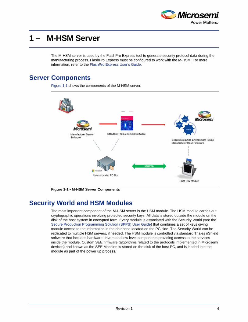
Server ComponentsFigure 1-1 shows the components of the M-HSM server.
Security World and HSM ModulesThe most important component of the M-HSM server is the HSM module. The HSM module carries out cryptographic operations involving protected security keys. All data is stored outside the module on the disk of the host system in encrypted form. Every module is associated with the Security World (see the Secure Production Programming Solution (SPPS) User Guide) that combines a set of keys giving module access to the information in the database located on the PC side. The Security World can be replicated to multiple HSM servers, if needed. The HSM module is controlled via standard Thales nShield software that includes hardware drivers and low level components providing access to the services inside the module. Custom SEE firmware (algorithms related to the protocols implemented in Microsemi devices) and known as the SEE Machine is stored on the disk of the host PC, and is loaded into the module as part of the power up process.
Figure 1-1 • M-HSM Server Components
Revision 1 4
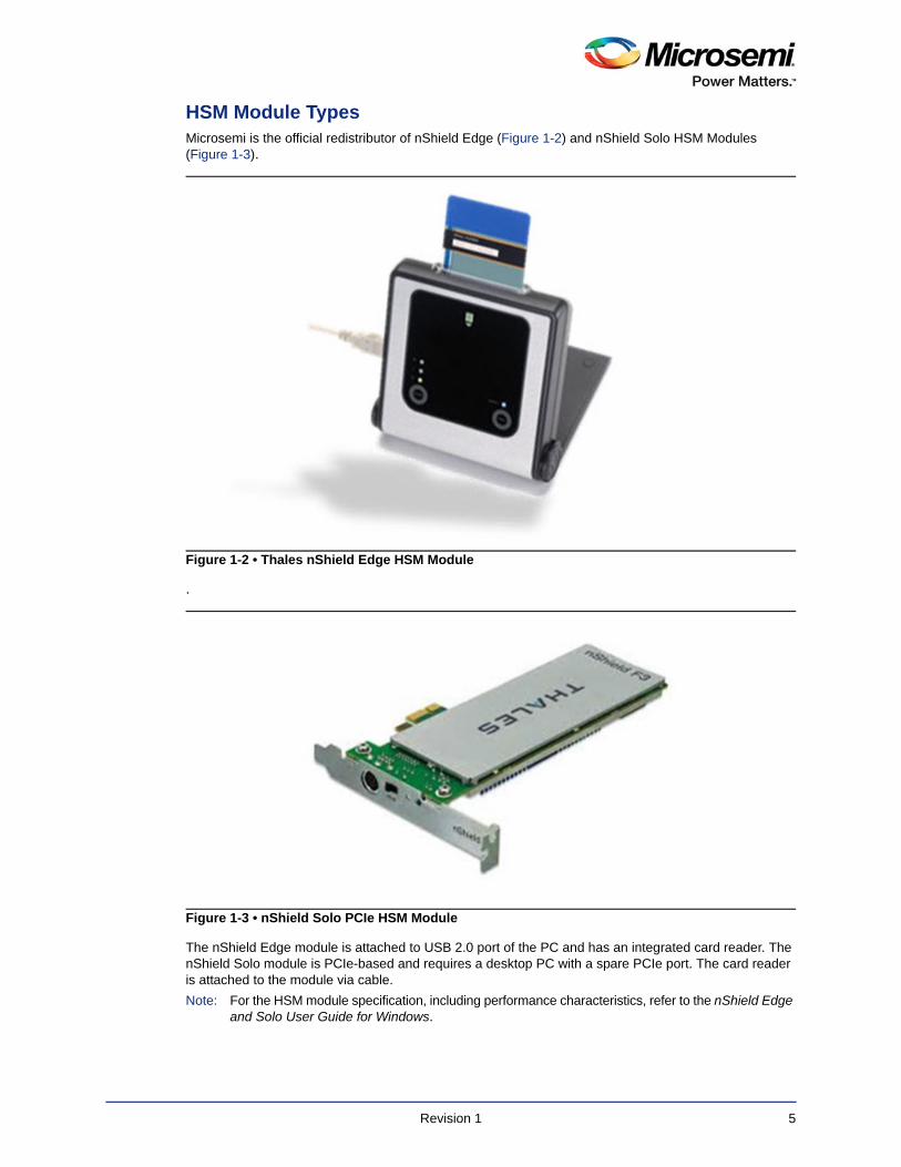
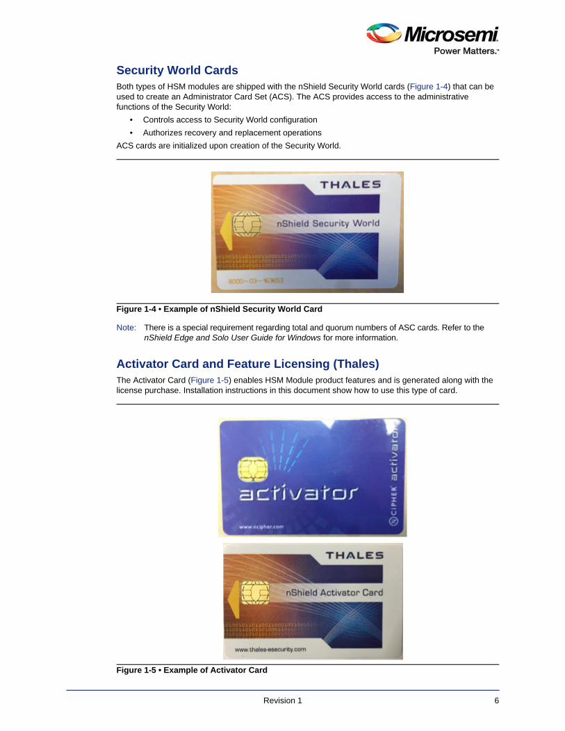
HSM Module TypesMicrosemi is the official redistributor of nShield Edge (Figure 1-2) and nShield Solo HSM Modules (Figure 1-3).
.
The nShield Edge module is attached to USB 2.0 port of the PC and has an integrated card reader. The nShield Solo module is PCIe-based and requires a desktop PC with a spare PCIe port. The card reader is attached to the module via cable.
Note: For the HSM module specification, including performance characteristics, refer to the nShield Edge and Solo User Guide for Windows.
Figure 1-2 • Thales nShield Edge HSM Module
Figure 1-3 • nShield Solo PCIe HSM Module
Revision 1 5
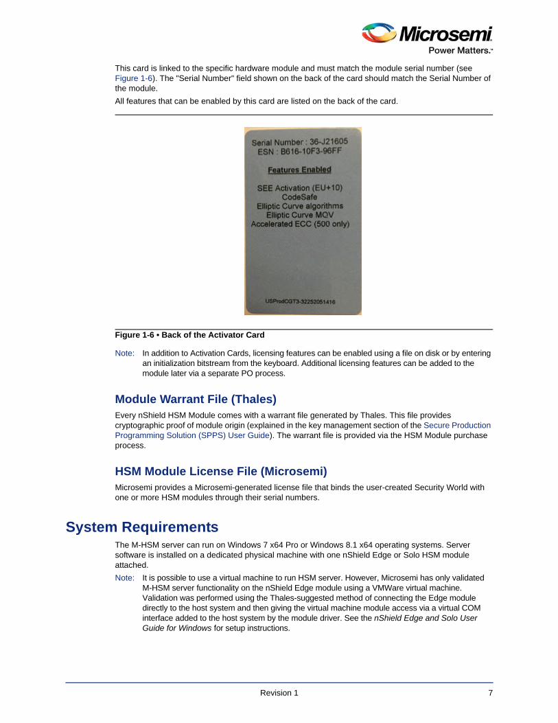
Security World CardsBoth types of HSM modules are shipped with the nShield Security World cards (Figure 1-4) that can be used to create an Administrator Card Set (ACS). The ACS provides access to the administrative functions of the Security World:
• Controls access to Security World configuration
• Authorizes recovery and replacement operations
ACS cards are initialized upon creation of the Security World.
Note: There is a special requirement regarding total and quorum numbers of ASC cards. Refer to the nShield Edge and Solo User Guide for Windows for more information.
Activator Card and Feature Licensing (Thales)The Activator Card (Figure 1-5) enables HSM Module product features and is generated along with the license purchase. Installation instructions in this document show how to use this type of card.
Figure 1-4 • Example of nShield Security World Card
Figure 1-5 • Example of Activator Card
Revision 1 6
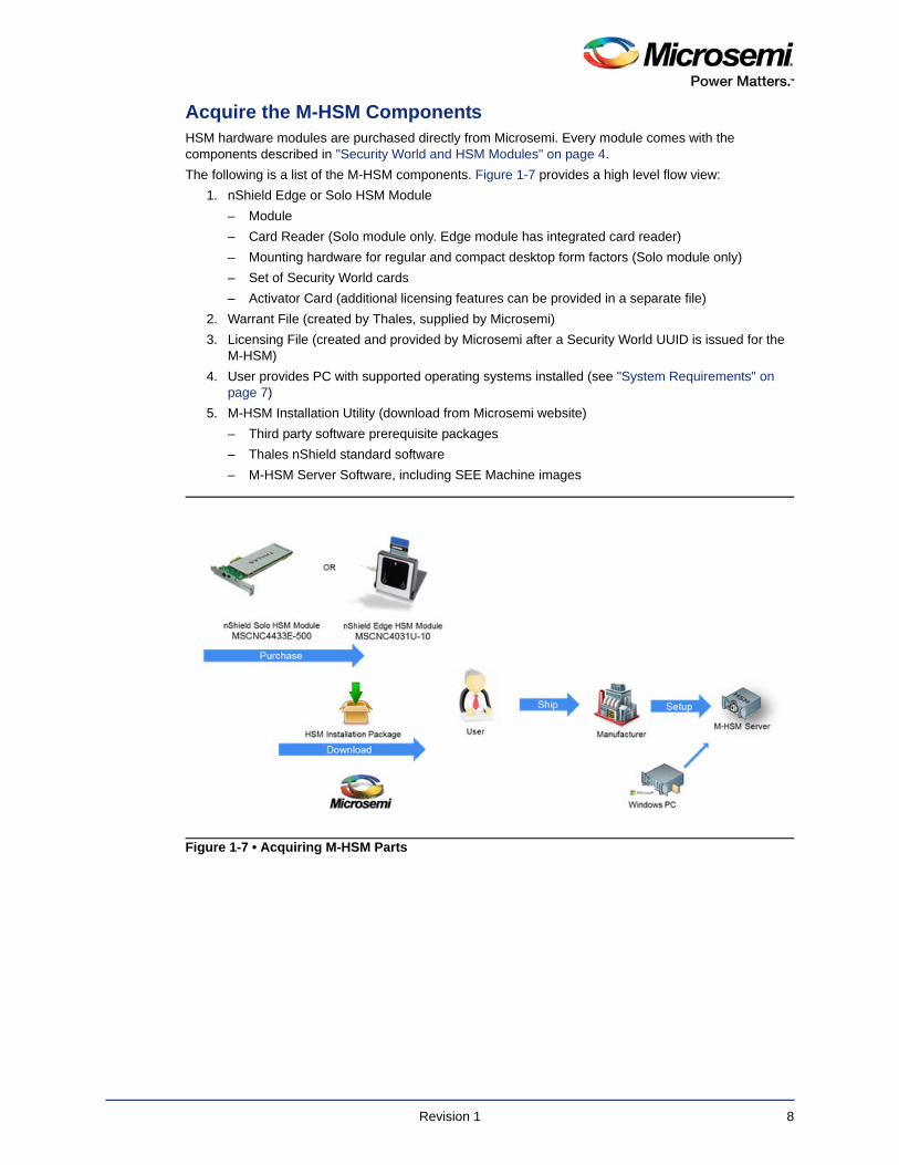
This card is linked to the specific hardware module and must match the module serial number (see Figure 1-6). The "Serial Number" field shown on the back of the card should match the Serial Number of the module.
All features that can be enabled by this card are listed on the back of the card.
Note: In addition to Activation Cards, licensing features can be enabled using a file on disk or by entering an initialization bitstream from the keyboard. Additional licensing features can be added to the module later via a separate PO process.
Module Warrant File (Thales)Every nShield HSM Module comes with a warrant file generated by Thales. This file provides cryptographic proof of module origin (explained in the key management section of the Secure Production Programming Solution (SPPS) User Guide). The warrant file is provided via the HSM Module purchase process.
HSM Module License File (Microsemi)Microsemi provides a Microsemi-generated license file that binds the user-created Security World with one or more HSM modules through their serial numbers.
System RequirementsThe M-HSM server can run on Windows 7 x64 Pro or Windows 8.1 x64 operating systems. Server software is installed on a dedicated physical machine with one nShield Edge or Solo HSM module attached.
Note: It is possible to use a virtual machine to run HSM server. However, Microsemi has only validated M-HSM server functionality on the nShield Edge module using a VMWare virtual machine. Validation was performed using the Thales-suggested method of connecting the Edge module directly to the host system and then giving the virtual machine module access via a virtual COM interface added to the host system by the module driver. See the nShield Edge and Solo User Guide for Windows for setup instructions.
Figure 1-6 • Back of the Activator Card
Revision 1 7
Acquire the M-HSM ComponentsHSM hardware modules are purchased directly from Microsemi. Every module comes with the components described in "Security World and HSM Modules" on page 4.
The following is a list of the M-HSM components. Figure 1-7 provides a high level flow view:
1. nShield Edge or Solo HSM Module
– Module
– Card Reader (Solo module only. Edge module has integrated card reader)
– Mounting hardware for regular and compact desktop form factors (Solo module only)
– Set of Security World cards
– Activator Card (additional licensing features can be provided in a separate file)
2. Warrant File (created by Thales, supplied by Microsemi)
3. Licensing File (created and provided by Microsemi after a Security World UUID is issued for the M-HSM)
4. User provides PC with supported operating systems installed (see "System Requirements" on page 7)
5. M-HSM Installation Utility (download from Microsemi website)
– Third party software prerequisite packages
– Thales nShield standard software
– M-HSM Server Software, including SEE Machine images
Figure 1-7 • Acquiring M-HSM Parts
Revision 1 8
Revision 1 9
2 – M-HSM Installation and Setup Scenarios
This User Guide describes the following installation and setup options:
1. Initial setup
a. Install all required software components.
b. Update all required configuration files.
c. Install the HSM module.
d. Provision the M-HSM server.
– Create new Security World and Administrator Card Set (ACS).
– Generate all required keys.
– Exchange public keys with the U-HSM and send public key to the Microsemi MFG server .
– Import Diversified Factory Key Database (DFK DB) and the manufacturing keys received from the U-HSM.
2. Post-installation (maintenance) steps
a. Upgrade the HSM Module Firmware.
b. Replace the HSM module.
c. Import the public key of another U-HSM.
d. Export the public key for sending to a U-HSM.
e. Import new DFK DB and Manufacturing keys for the target Microsemi device(s).
3. Replication of the existing M-HSM server (creates a copy of already provisioned M-HSM server)
a. Install all required software components.
b. Copy over Security World from the source M-HSM server.
c. Copy over the M-HSM server software.
d. Copy over the existing DFK DB.
e. Install and connect new HSM module to the Security World and install module license file.
3 – Initial M-HSM Server Installation and Setup
This chapter describes how to install and set up a new M-HSM server.
Note: Text highlighted in red in this chapter indicates commands and other information to take note of.
Software InstallationM-HSM server software installation is normally done using the Microsemi M-HSM installation utility. This section explains the manual installation process.
One of the supported operating systems must be installed with all security and stability updates applied.
1. Microsoft Visual C++ 2010 Redistributable Package (x64) available from Microsoft
2. Visual C++ Redistributable for Visual Studio 2012 (x64) available from Microsoft
3. .NET Framework 4.0 or up available from Microsoft
4. FTP Server (e.g. FileZilla)
5. Java Runtime 2 available from Oracle
6. Latest version of the nShield Security World Software (comes with the HSM modules).
– The installation disk contains a folder with documentation in PDF format.
– Installation of SNMP client can be ignored as the software for this implementation does not use it.
– The default installation directory for the Security World is C:\Program Files (x86)\nCipher\nfast.
– All Security World utilities referred to in this guide are located in %NFAST_HOME%\bin.
– The Microsemi SPPS solution is tested against the specific version of the Security World. Refer to the M-HSM server Release Notes for the compatible version number.
M-HSM Server Software Installation1. Create the top level directory.
Note: This User Guide uses C:\Microsemi as an example
2. Unpack all files and subdirectories from the provided zip file under the M-HSM directory and copy to C:\Microsemi.
3. Verify that the following additional subdirectories exist:
– C:\Microsemi\DFKDB - This location will be used for storing imported DFK databases
– C:\Microsemi\JobDB - This location will store job ticket database files
– C:\Microsemi\JobDB\JobDBArchive - Folder for archiving completed job ticket database files
– C:\Microsemi\Logs - For log files
HSM Hardware Module InstallationNote: This section provides the steps to connect a new HSM module to the PC. If you are replacing the
HSM module on a configured M-HSM server, start from "HSM Module Replacement" on page 31. If you are replicating the M-HSM server, refer to "Set Up a New HSM Module" on page 31.
The M-HSM server requires the presence of a single HSM module. After the installation of nShield software, as shown in "Software Installation" on page 10, the system should have module drivers and all nShield utilities installed.
Revision 1 10
Connect the HSM Module to the PCFollow the instructions in the nShield Edge and Solo User Guide for Windows to physically connect the module to the PC.
Once the module is connected, read module status with the nfkminfo utility. The output of nfkminfo shows information about the attached module, such as ESN (serial number), status, etc. If the module is not detected or in the "failed" state, restart the nfast server and read the module status again:
net stop "nfast server"
net start "nfast server"
Note: If necessary, the HSM module can be erased to the factory state using the new-world command. Example: new-world -e -m1 erases the module with the ID=1 to the factory state. This operation is done in the pre-initialization mode.
Upgrade HSM Module Firmware This section provides instructions for Thales firmware upgrade. This firmware physically resides inside the HSM module and is different from the Microsemi-provided SEE machine.
Firmware RevisionsThe firmware revision of the HSM module that is used in SPPS must be approved by Microsemi. The list of the approved firmware revisions is available in the M-HSM Release Notes. Additional instructions about firmware revisions may be published via Microsemi security advisories.
Note: Any HSM firmware revision that is not approved by Microsemi is not guaranteed to work and is not guaranteed to satisfy security requirements of the SPPS solution. The use of such firmware revisions is done at customer's own risk.
Thales HSM module firmware images are available in the HSM Installation media, or can be obtained directly from Thales customer service.
Note: Installation media may include various versions of the firmware that may be FIPS certified or awaiting FIPS certification. Your choice depends on the security policies of your organization.
Compatibility of Firmware RevisionsWarning! The firmware upgrade may be non-reversible. Read this section for important details.
Thales HSM module firmware has two versioning characteristics:
• Firmware revision number
• Version Security Number (VSN)
The firmware revision number identifies the individual version of the firmware, while the VSN can group multiple revisions together and is used to restrict revision downgrade, so that intruders cannot move a module to the firmware with known security issues. The downgrade is possible to any firmware revision with the same VSN as the one in the module. The upgrade can be done to any revision with the same or higher VSN number.
Information about firmware revisions and their respective VSN numbers is available on the Security World installation media of firmware upgrade media distributed as part of Thales security advisories.
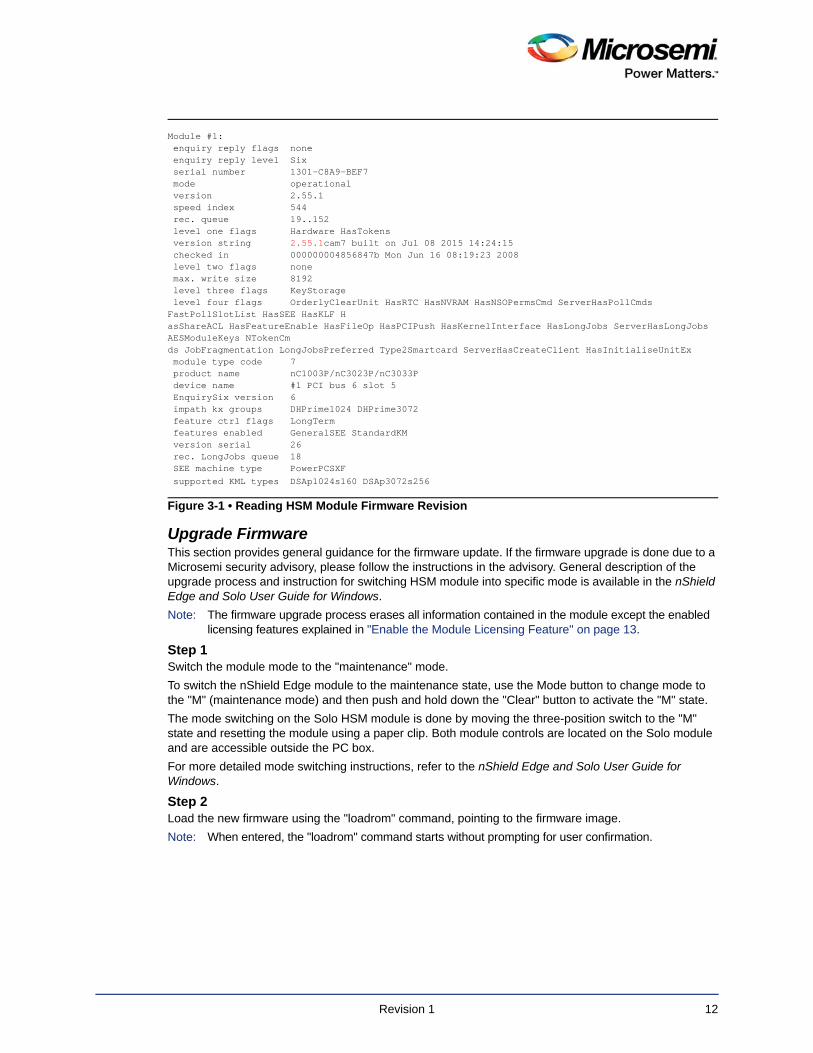
Read the HSM Module Firmware Revision InfoThe current revision of the HSM firmware can be checked using the "enquiry" Security World utility.
An example of reading the firmware revision number is shown in Figure 3-1.
Revision 1 11
Upgrade Firmware This section provides general guidance for the firmware update. If the firmware upgrade is done due to a Microsemi security advisory, please follow the instructions in the advisory. General description of the upgrade process and instruction for switching HSM module into specific mode is available in the nShield Edge and Solo User Guide for Windows.
Note: The firmware upgrade process erases all information contained in the module except the enabled licensing features explained in "Enable the Module Licensing Feature" on page 13.
Step 1Switch the module mode to the "maintenance" mode.
To switch the nShield Edge module to the maintenance state, use the Mode button to change mode to the "M" (maintenance mode) and then push and hold down the "Clear" button to activate the "M" state.
The mode switching on the Solo HSM module is done by moving the three-position switch to the "M" state and resetting the module using a paper clip. Both module controls are located on the Solo module and are accessible outside the PC box.
For more detailed mode switching instructions, refer to the nShield Edge and Solo User Guide for Windows.
Step 2Load the new firmware using the "loadrom" command, pointing to the firmware image.
Note: When entered, the "loadrom" command starts without prompting for user confirmation.
Module #1: enquiry reply flags none enquiry reply level Six serial number 1301-C8A9-BEF7 mode operational version 2.55.1 speed index 544 rec. queue 19..152 level one flags Hardware HasTokens version string 2.55.1cam7 built on Jul 08 2015 14:24:15 checked in 000000004856847b Mon Jun 16 08:19:23 2008 level two flags none max. write size 8192 level three flags KeyStorage level four flags OrderlyClearUnit HasRTC HasNVRAM HasNSOPermsCmd ServerHasPollCmds FastPollSlotList HasSEE HasKLF HasShareACL HasFeatureEnable HasFileOp HasPCIPush HasKernelInterface HasLongJobs ServerHasLongJobs AESModuleKeys NTokenCmds JobFragmentation LongJobsPreferred Type2Smartcard ServerHasCreateClient HasInitialiseUnitEx module type code 7 product name nC1003P/nC3023P/nC3033P device name #1 PCI bus 6 slot 5 EnquirySix version 6 impath kx groups DHPrime1024 DHPrime3072 feature ctrl flags LongTerm features enabled GeneralSEE StandardKM version serial 26 rec. LongJobs queue 18 SEE machine type PowerPCSXF supported KML types DSAp1024s160 DSAp3072s256
Figure 3-1 • Reading HSM Module Firmware Revision
Revision 1 12
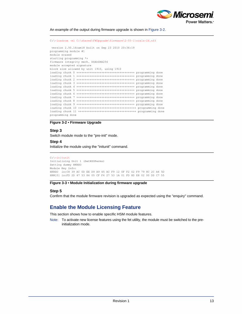
An example of the output during firmware upgrade is shown in Figure 3-2.
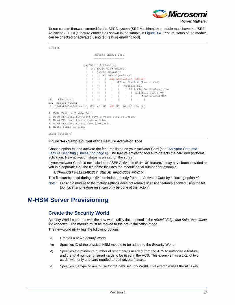
Step 3Switch module mode to the "pre-init" mode.
Step 4Initialize the module using the "initunit" command.
Step 5Confirm that the module firmware revision is upgraded as expected using the "enquiry" command.
Enable the Module Licensing Feature This section shows how to enable specific HSM module features.
Note: To activate new license features using the fet utility, the module must be switched to the pre-initialization mode.
C:\>loadrom -m1 C:\shared\FWUpgrade\firmware\2-55-1\ncx1z-26.nff
version 2.50.16cam18 built on Sep 23 2010 20:36:19programming module #1module erasedstarting programming *+firmware integrity mech. DSAhSHA256module accepted signatureblock size allowed by unit 1910, using 1910loading chunk 0 +++++++++++++++++++++++++++++++++++ programming doneloading chunk 1 +++++++++++++++++++++++++++++++++++ programming doneloading chunk 2 +++++++++++++++++++++++++++++++++++ programming doneloading chunk 3 +++++++++++++++++++++++++++++++++++ programming doneloading chunk 4 +++++++++++++++++++++++++++++++++++ programming doneloading chunk 5 +++++++++++++++++++++++++++++++++++ programming doneloading chunk 6 +++++++++++++++++++++++++++++++++++ programming doneloading chunk 7 +++++++++++++++++++++++++++++++++++ programming doneloading chunk 8 +++++++++++++++++++++++++++++++++++ programming doneloading chunk 9 +++++++++++++++++++++++++++++++++++ programming doneloading chunk 10 +++++++++++++++++++++++++++++++++++ programming doneloading chunk 11 +++++++++++++++++++++++++++++++++++ programming doneprogramming done
Figure 3-2 • Firmware Upgrade
C:\>initunitInitialising Unit 1 (SetNSOPerms)Setting dummy HKNSOModule Key Info:HKNSO is:C8 39 AC 0D EE D9 A9 65 AC F9 12 0F F2 02 F9 79 8C 2C A4 5DHKM[0] is:FD 2D 47 53 86 05 CF F4 27 53 1A 01 FD 8D E8 02 00 DD C7 55
Figure 3-3 • Module Initialization during firmware upgrade
Revision 1 13
To run custom firmware created for the SPPS system (SEE Machine), the module must have the "SEE Activation (EU+10)" feature enabled as shown in the sample in Figure 3-4. Feature status of the module can be checked or activated using fet (feature enabling tool).
Choose option #1 and activate the features listed on your Activator Card (see "Activator Card and Feature Licensing (Thales)" on page 6). The feature activating tool auto-detects the card and performs activation. New activation status is printed on the screen.
If your Activator Card did not include the "SEE Activation (EU+10)" feature, it may have been provided to you in a separate file. The file name includes the module serial number, for example:
USProdCGT3-01253481317_SEEUE_8FD6-2609-F7A2.txt
This file can be used during activation independently from the Activator Card by selecting option #2.
Note: Erasing a module to the factory settings does not remove licensing features enabled using the fet tool. Licensing feature reset can only be done at the factory.
M-HSM Server Provisioning
Create the Security WorldSecurity World is created with the new-world utility documented in the nShield Edge and Solo User Guide for Windows . The module must be moved to the pre-initialization mode.
The new-world utility has the following options.
C:\>fet
Feature Enable Tool ===================
payShield Activation | ISO Smart Card Support | | Remote Operator | | | Korean Algorithms | | | | SEE Activation (EU+10) | | | | | SEE Activation (Restricted) | | | | | | CodeSafe SSL | | | | | | | Elliptic Curve algorithms | | | | | | | | Elliptic Curve MQV | | | | | | | | | Accelerated ECCMod Electronic | | | | | | | | | |No. Serial Number 1 586F-B963-9146 -- NO NO NO NO YES NO NO NO NO NO
0. Exit Feature Enable Tool.1. Read FEM certificate(s) from a smart card or cards.2. Read FEM certificate from a file.3. Read FEM certificate from keyboard.4. Write table to file.
Enter option :
Figure 3-4 • Sample output of the Feature Activation Tool
-i Creates a new Security World.
-m Specifies ID of the physical HSM module to be added to the Security World.
-Q Specifies the minimum number of smart cards needed from the ACS to authorize a feature and the total number of smart cards to be used in the ACS. This example has a total of two cards, with only one card needed to authorize a feature.
-c Specifies the type of key to use for the new Security World. This example uses the AES key.
Revision 1 14

The example shown in Figure 3-5 creates a new Security World.
During creation of the Security World, the user is prompted to insert and initialize all ACS cards specified by the -Q option.
Tip: The values of the hknso parameters can be used to uniquely identify the Security World.
Tip: If the module is not in the pre-initialization state, creation of the Security World may encounter an error, as shown in Figure 3-6.
The new Security World is a file that is created in the following location: %NFAST_KMDATA%\local
Note: This location also contains all other related security keys.
Once the Security World is created, the module must be moved to the operational mode.
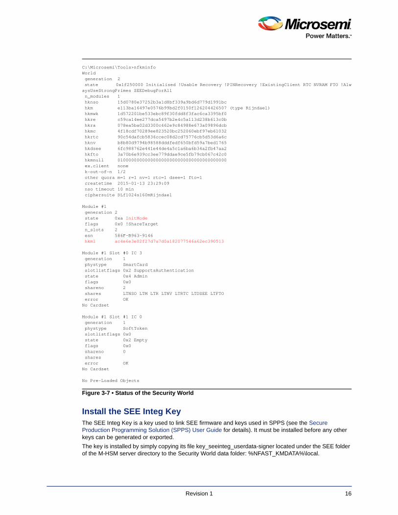
Read the Status of the Security World The status information related to the existing Security World and attached module(s) can be viewed using the nfkminfo utility. Refer to the nShield Edge and Solo User Guide for Windows for more information.
This status information contains several important fields. The hknso and hkm fields allow the user to uniquely identify the specific Security World.
Once a module is moved to the operational state, the module status read by nfkminfo should indicate "usable" module state.
Figure 3-7 shows sample output of the nfkminfo utility.
C:\Microsemi\Tools>new-world -i -m 1 -Q 1/2 -c DLf1024s160mRijndael dseeall
Create Security World: Module 1: 0 cards of 2 written Module 1 slot 0: empty Module 1 slot 0: unknown card Module 1 slot 0:- no passphrase specified - overwriting card Module 1: 1 card of 2 written Module 1 slot 0: remove already-written card #1 Module 1 slot 0: empty Module 1 slot 0: unknown card Module 1 slot 0:- no passphrase specified - overwriting cardCard writing complete.
security world generated on module #1; hknso = 15d0780e37252b3a1d8bf339a9bd6d779d1991bc
Figure 3-5 • Sample output from creation of new Security World
12:46:57 WARNING: Module #1: Module has failednew-world: module 1 not suitable: module key type Rijndael not supportednew-world: Aborting world operation.
Figure 3-6 • Error message if module is not in pre-initialization state
Revision 1 15
Install the SEE Integ KeyThe SEE Integ Key is a key used to link SEE firmware and keys used in SPPS (see the Secure Production Programming Solution (SPPS) User Guide for details). It must be installed before any other keys can be generated or exported.
The key is installed by simply copying its file key_seeinteg_userdata-signer located under the SEE folder of the M-HSM server directory to the Security World data folder: %NFAST_KMDATA%\local.
C:\Microsemi\Tools>nfkminfoWorld generation 2 state 0x1f250000 Initialised !Usable Recovery !PINRecovery !ExistingClient RTC NVRAM FTO !AlwaysUseStrongPrimes SEEDebugForAll n_modules 1 hknso 15d0780e37252b3a1d8bf339a9bd6d779d1991bc hkm e113ba16497e0576b99bd2f0150f126204426507 (type Rijndael) hkmwk 1d572201be533ebc89f30fdd8f3fac6ca3395bf0 hkre c59ca14ee277dca5497b2e4c5a113d238b613c0b hkra 078ea5ba02d3300c462e9c84988e673a09896dcb hkmc 4f18cdf70289ee823520bc252060ebf97eb61032 hkrtc 90c54dafcb5836ccec08d2cd75776cb5d53d6a6c hknv b8b80d9794b98588dddfedf650bfd59a7bed1765 hkdsee 6fc988762e441e44de4a5c1a6ba6b34a2fb47aa2 hkfto 3a70b6e939cc3ee779ddae9ce5fb79cb067c42c0 hkmnull 0100000000000000000000000000000000000000 ex.client none k-out-of-n 1/2 other quora m=1 r=1 nv=1 rtc=1 dsee=1 fto=1 createtime 2015-01-13 23:29:09 nso timeout 10 min ciphersuite DLf1024s160mRijndael
Module #1 generation 2 state 0xa InitMode flags 0x0 !ShareTarget n_slots 2 esn 586F-B963-9146 hkml ac4e6e3e02f27d7a7d0a182077546a62ec390513
Module #1 Slot #0 IC 3 generation 1 phystype SmartCard slotlistflags 0x2 SupportsAuthentication state 0x4 Admin flags 0x0 shareno 2 shares LTNSO LTM LTR LTNV LTRTC LTDSEE LTFTO error OKNo Cardset
Module #1 Slot #1 IC 0 generation 1 phystype SoftToken slotlistflags 0x0 state 0x2 Empty flags 0x0 shareno 0 shares error OKNo Cardset
No Pre-Loaded Objects
Figure 3-7 • Status of the Security World
Revision 1 16
Example: copy C:\Microsemi\SEE\key_seeinteg_userdata-signer %NFAST_KMDATA%\local
Proper installation of the SEE Signer Key can be confirmed using the "nfkminfo -k" command, as shown in Figure 3-8.
Get Hash of the SEE Integ KeyThe hash of the signer key is used for key identification and referencing key signer during various operations such as creation of the HSM private/public key pairs.
The hash value of the key signer can be retrieved using nfkminfo:
nfkminfo -k seeinteg userdata-signer | find "hash"
See the example below:
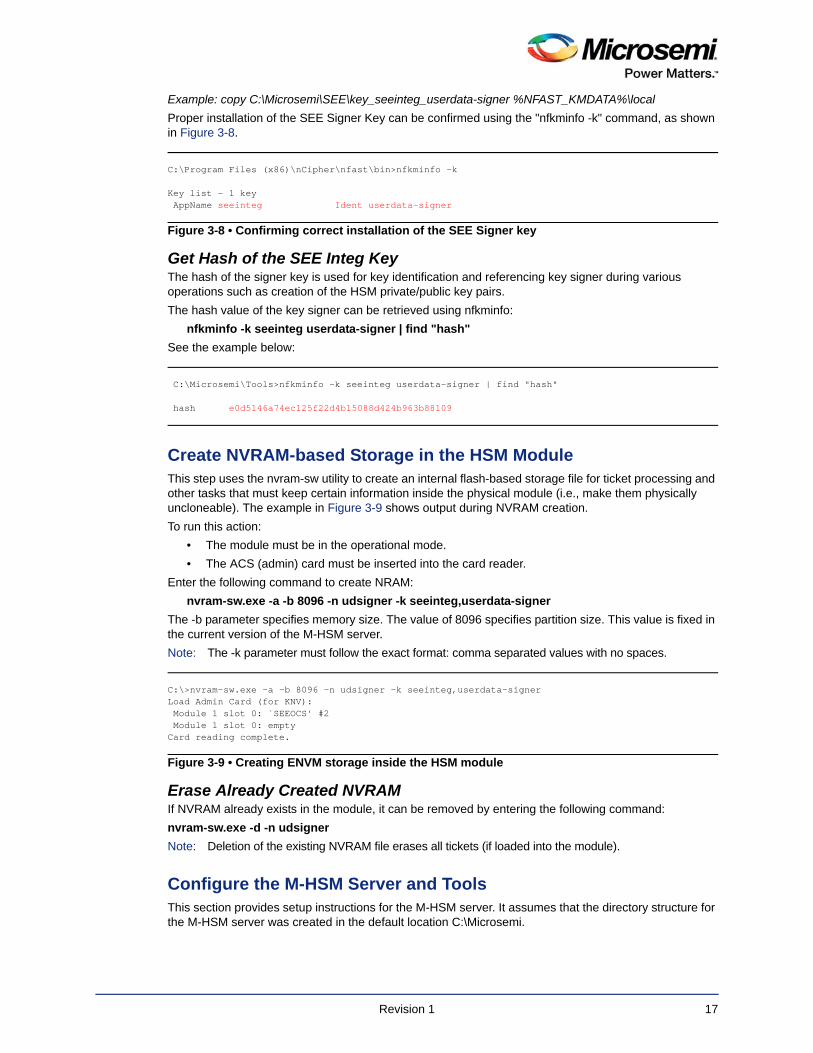
Create NVRAM-based Storage in the HSM ModuleThis step uses the nvram-sw utility to create an internal flash-based storage file for ticket processing and other tasks that must keep certain information inside the physical module (i.e., make them physically uncloneable). The example in Figure 3-9 shows output during NVRAM creation.
To run this action:
• The module must be in the operational mode.
• The ACS (admin) card must be inserted into the card reader.
Enter the following command to create NRAM:
nvram-sw.exe -a -b 8096 -n udsigner -k seeinteg,userdata-signer
The -b parameter specifies memory size. The value of 8096 specifies partition size. This value is fixed in the current version of the M-HSM server.
Note: The -k parameter must follow the exact format: comma separated values with no spaces.
Erase Already Created NVRAMIf NVRAM already exists in the module, it can be removed by entering the following command:
nvram-sw.exe -d -n udsigner
Note: Deletion of the existing NVRAM file erases all tickets (if loaded into the module).
Configure the M-HSM Server and Tools This section provides setup instructions for the M-HSM server. It assumes that the directory structure for the M-HSM server was created in the default location C:\Microsemi.
C:\Program Files (x86)\nCipher\nfast\bin>nfkminfo -k
Key list - 1 key AppName seeinteg Ident userdata-signer
Figure 3-8 • Confirming correct installation of the SEE Signer key
C:\Microsemi\Tools>nfkminfo -k seeinteg userdata-signer | find "hash"
hash e0d5146a74ec125f22d4b15088d424b963b88109
C:\>nvram-sw.exe -a -b 8096 -n udsigner -k seeinteg,userdata-signerLoad Admin Card (for KNV): Module 1 slot 0: `SEEOCS' #2 Module 1 slot 0: emptyCard reading complete.
Figure 3-9 • Creating ENVM storage inside the HSM module
Revision 1 17
Update Server and Tools Configuration FileThe M-HSMMaster.config file contains settings for the M-HSM server. Currently, there are two separate config files with the same name and identical content. For the default installation location, the file path is:
C:\Microsemi\Server\M-HSMMaster.config
and
C:\Microsemi\Tools\M-HSMMaster.config
Change the following settings as shown:
1. DFK database location - confirm the location matches actual path:
<add key="G4HSMAPI.DFKDBPath" value="C:\Microsemi\DFKDB" />
2. Ticket database location - confirm the location matches actual path:
<add key="G4HSMAPI.JobTicketDBPath" value="C:\Microsemi\JobDB"/>
3. Ticket archive directory:
<add key="G4HSMAPI.JTPLogArchivePath" value="C:\Microsemi\JobDB\JobDBArchive"/>
4. M-HSM UUID 40 symbols long hex string obtained from Microsemi (00..02 in this example):
<add key="My_UUID" value="0000000000000000000000000000000000000002"/>
5. SEEK Secret key: g4cm-seesk-<M_HSM_UUID> (00..02 in this example):
<add key="G4HSMAPI.CSEEKey" value="g4cm-seesk-0000000000000000000000000000000000000002" />
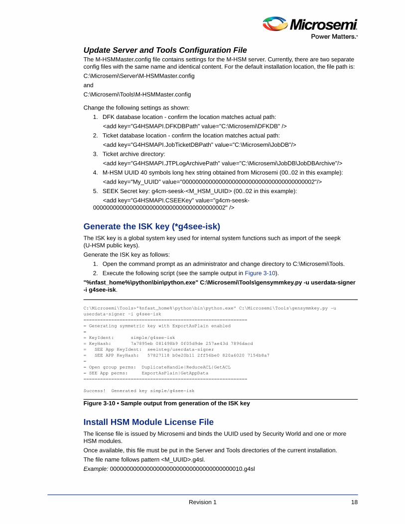
Generate the ISK key (*g4see-isk)The ISK key is a global system key used for internal system functions such as import of the seepk (U-HSM public keys).
Generate the ISK key as follows:
1. Open the command prompt as an administrator and change directory to C:\Microsemi\Tools.
2. Execute the following script (see the sample output in Figure 3-10).
"%nfast_home%\python\bin\python.exe" C:\Microsemi\Tools\gensymmkey.py -u userdata-signer -i g4see-isk.
Install HSM Module License FileThe license file is issued by Microsemi and binds the UUID used by Security World and one or more HSM modules.
Once available, this file must be put in the Server and Tools directories of the current installation.
The file name follows pattern <M_UUID>.g4sl.
Example: 0000000000000000000000000000000000000010.g4sl
C:\Microsemi\Tools>"%nfast_home%\python\bin\python.exe" C:\Microsemi\Tools\gensymmkey.py -u userdata-signer -i g4see-isk============================================================ Generating symmetric key with ExportAsPlain enabled== KeyIdent: simple/g4see-isk= KeyHash: 7a7895eb 081498b9 0f05d9de 257ae43d 7896dacd= SEE App KeyIdent: seeinteg/userdata-signer= SEE APP KeyHash: 57827118 b0e20b11 2ff56be0 820a6020 7154b8a7== Open group perms: DuplicateHandle|ReduceACL|GetACL= SEE App perms: ExportAsPlain|GetAppData===========================================================
Success! Generated key simple/g4see-isk
Figure 3-10 • Sample output from generation of the ISK key
Revision 1 18
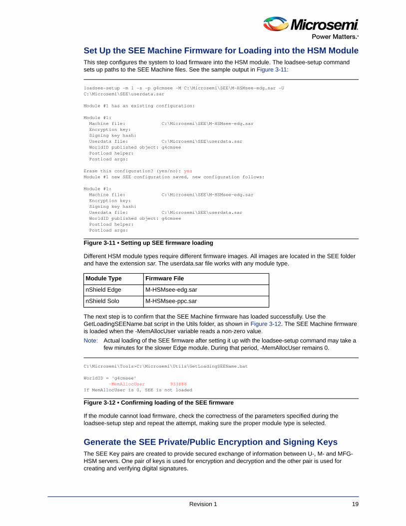
Set Up the SEE Machine Firmware for Loading into the HSM ModuleThis step configures the system to load firmware into the HSM module. The loadsee-setup command sets up paths to the SEE Machine files. See the sample output in Figure 3-11:
Different HSM module types require different firmware images. All images are located in the SEE folder and have the extension sar. The userdata.sar file works with any module type.
The next step is to confirm that the SEE Machine firmware has loaded successfully. Use the GetLoadingSEEName.bat script in the Utils folder, as shown in Figure 3-12. The SEE Machine firmware is loaded when the -MemAllocUser variable reads a non-zero value.
Note: Actual loading of the SEE firmware after setting it up with the loadsee-setup command may take a few minutes for the slower Edge module. During that period, -MemAllocUser remains 0.
If the module cannot load firmware, check the correctness of the parameters specified during the loadsee-setup step and repeat the attempt, making sure the proper module type is selected.
Generate the SEE Private/Public Encryption and Signing KeysThe SEE Key pairs are created to provide secured exchange of information between U-, M- and MFG-HSM servers. One pair of keys is used for encryption and decryption and the other pair is used for creating and verifying digital signatures.
loadsee-setup -m 1 -s -p g4cmsee -M C:\Microsemi\SEE\M-HSMsee-edg.sar -U C:\Microsemi\SEE\userdata.sar
Module #1 has an existing configuration:
Module #1: Machine file: C:\Microsemi\SEE\M-HSMsee-edg.sar Encryption key: Signing key hash: Userdata file: C:\Microsemi\SEE\userdata.sar WorldID published object: g4cmsee Postload helper: Postload args:
Erase this configuration? (yes/no): yesModule #1 new SEE configuration saved, new configuration follows:
Module #1: Machine file: C:\Microsemi\SEE\M-HSMsee-edg.sar Encryption key: Signing key hash: Userdata file: C:\Microsemi\SEE\userdata.sar WorldID published object: g4cmsee Postload helper: Postload args:
Figure 3-11 • Setting up SEE firmware loading
Module Type Firmware File
nShield Edge M-HSMsee-edg.sar
nShield Solo M-HSMsee-ppc.sar
C:\Microsemi\Tools>C:\Microsemi\Utils\GetLoadingSEEName.bat
WorldID = 'g4cmsee' -MemAllocUser 933888If MemAllocUser is 0, SEE is not loaded
Figure 3-12 • Confirming loading of the SEE firmware
Revision 1 19
Obtain the Manufacturer UUID from MicrosemiManufacturer UUID (M_UUID) is a 40-symbol hex string identifier that is assigned by Microsemi via the Microsemi Portal (see the Secure Production Programming Solution (SPPS) User Guide for details).
Example of the Manufacturer UUID: "38629b7388554a0381b85617329425e8678c384b"
Note: UUID must have all lower case characters.
Private/Public SEE keys must use the Manufacturer UUID assigned by Microsemi.
Once the UUID value is available, update the tag in both M-HSMMaster.config files, under the server and tools directories, as explained in "Update Server and Tools Configuration File" on page 18.
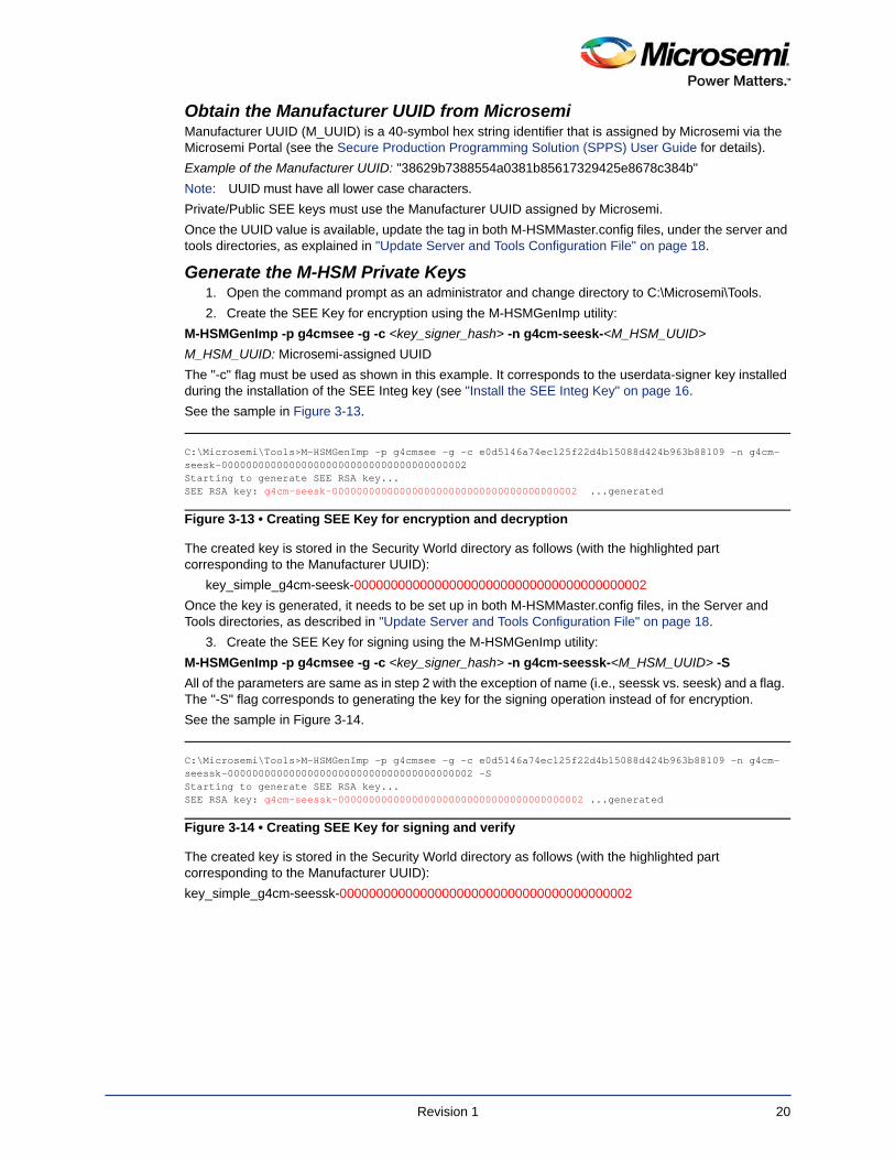
Generate the M-HSM Private Keys1. Open the command prompt as an administrator and change directory to C:\Microsemi\Tools.
2. Create the SEE Key for encryption using the M-HSMGenImp utility:
M-HSMGenImp -p g4cmsee -g -c <key_signer_hash> -n g4cm-seesk-<M_HSM_UUID>
M_HSM_UUID: Microsemi-assigned UUID
The "-c" flag must be used as shown in this example. It corresponds to the userdata-signer key installed during the installation of the SEE Integ key (see "Install the SEE Integ Key" on page 16.
See the sample in Figure 3-13.
The created key is stored in the Security World directory as follows (with the highlighted part corresponding to the Manufacturer UUID):
key_simple_g4cm-seesk-0000000000000000000000000000000000000002
Once the key is generated, it needs to be set up in both M-HSMMaster.config files, in the Server and Tools directories, as described in "Update Server and Tools Configuration File" on page 18.
3. Create the SEE Key for signing using the M-HSMGenImp utility:
M-HSMGenImp -p g4cmsee -g -c <key_signer_hash> -n g4cm-seessk-<M_HSM_UUID> -S
All of the parameters are same as in step 2 with the exception of name (i.e., seessk vs. seesk) and a flag. The "-S" flag corresponds to generating the key for the signing operation instead of for encryption.
See the sample in Figure 3-14.
The created key is stored in the Security World directory as follows (with the highlighted part corresponding to the Manufacturer UUID):
key_simple_g4cm-seessk-0000000000000000000000000000000000000002
C:\Microsemi\Tools>M-HSMGenImp -p g4cmsee -g -c e0d5146a74ec125f22d4b15088d424b963b88109 -n g4cm-seesk-0000000000000000000000000000000000000002Starting to generate SEE RSA key...SEE RSA key: g4cm-seesk-0000000000000000000000000000000000000002 ...generated
Figure 3-13 • Creating SEE Key for encryption and decryption
C:\Microsemi\Tools>M-HSMGenImp -p g4cmsee -g -c e0d5146a74ec125f22d4b15088d424b963b88109 -n g4cm- seessk-0000000000000000000000000000000000000002 -SStarting to generate SEE RSA key...SEE RSA key: g4cm-seessk-0000000000000000000000000000000000000002 ...generated
Figure 3-14 • Creating SEE Key for signing and verify
Revision 1 20
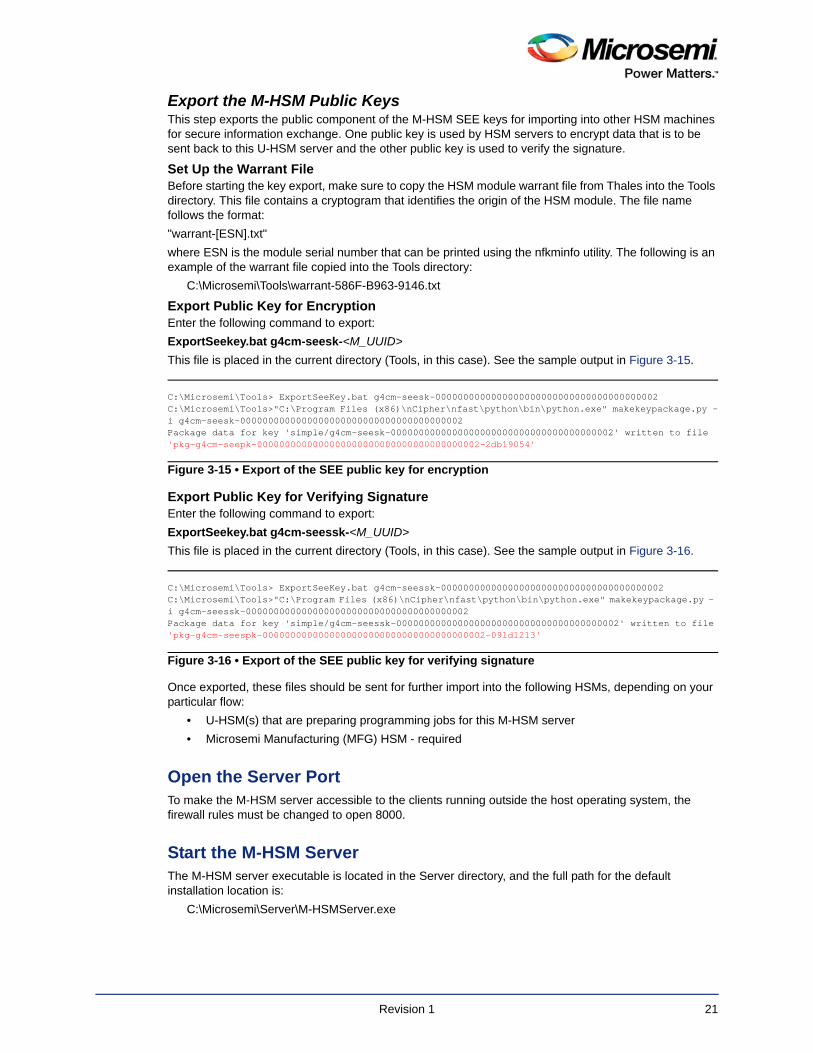
Export the M-HSM Public KeysThis step exports the public component of the M-HSM SEE keys for importing into other HSM machines for secure information exchange. One public key is used by HSM servers to encrypt data that is to be sent back to this U-HSM server and the other public key is used to verify the signature.
Set Up the Warrant FileBefore starting the key export, make sure to copy the HSM module warrant file from Thales into the Tools directory. This file contains a cryptogram that identifies the origin of the HSM module. The file name follows the format:
"warrant-[ESN].txt"
where ESN is the module serial number that can be printed using the nfkminfo utility. The following is an example of the warrant file copied into the Tools directory:
C:\Microsemi\Tools\warrant-586F-B963-9146.txt
Export Public Key for EncryptionEnter the following command to export:
ExportSeekey.bat g4cm-seesk-<M_UUID>
This file is placed in the current directory (Tools, in this case). See the sample output in Figure 3-15.
Export Public Key for Verifying SignatureEnter the following command to export:
ExportSeekey.bat g4cm-seessk-<M_UUID>
This file is placed in the current directory (Tools, in this case). See the sample output in Figure 3-16.
Once exported, these files should be sent for further import into the following HSMs, depending on your particular flow:
• U-HSM(s) that are preparing programming jobs for this M-HSM server
• Microsemi Manufacturing (MFG) HSM - required
Open the Server PortTo make the M-HSM server accessible to the clients running outside the host operating system, the firewall rules must be changed to open 8000.
Start the M-HSM ServerThe M-HSM server executable is located in the Server directory, and the full path for the default installation location is:
C:\Microsemi\Server\M-HSMServer.exe
C:\Microsemi\Tools> ExportSeeKey.bat g4cm-seesk-0000000000000000000000000000000000000002C:\Microsemi\Tools>"C:\Program Files (x86)\nCipher\nfast\python\bin\python.exe" makekeypackage.py -i g4cm-seesk-0000000000000000000000000000000000000002Package data for key 'simple/g4cm-seesk-0000000000000000000000000000000000000002' written to file 'pkg-g4cm-seepk-0000000000000000000000000000000000000002-2db19054'
Figure 3-15 • Export of the SEE public key for encryption
C:\Microsemi\Tools> ExportSeeKey.bat g4cm-seessk-0000000000000000000000000000000000000002C:\Microsemi\Tools>"C:\Program Files (x86)\nCipher\nfast\python\bin\python.exe" makekeypackage.py - i g4cm-seessk-0000000000000000000000000000000000000002Package data for key 'simple/g4cm-seessk-0000000000000000000000000000000000000002' written to file'pkg-g4cm-seespk-0000000000000000000000000000000000000002-091d1213'
Figure 3-16 • Export of the SEE public key for verifying signature
Revision 1 21
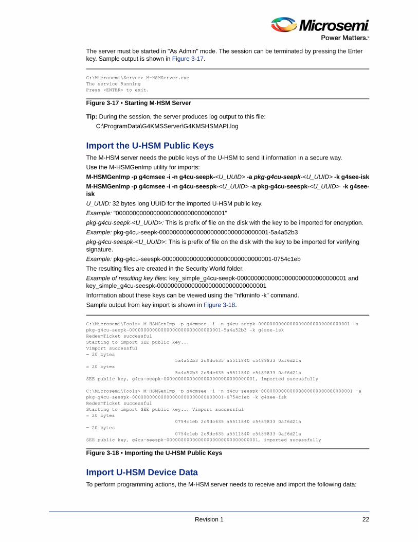
The server must be started in "As Admin" mode. The session can be terminated by pressing the Enter key. Sample output is shown in Figure 3-17.
Tip: During the session, the server produces log output to this file:
C:\ProgramData\G4KMSServer\G4KMSHSMAPI.log
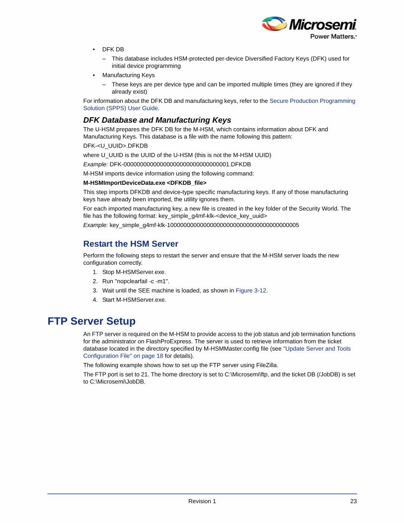
Import the U-HSM Public KeysThe M-HSM server needs the public keys of the U-HSM to send it information in a secure way.
Use the M-HSMGenImp utility for imports:
M-HSMGenImp -p g4cmsee -i -n g4cu-seepk-<U_UUID> -a pkg-g4cu-seepk-<U_UUID> -k g4see-isk
M-HSMGenImp -p g4cmsee -i -n g4cu-seespk-<U_UUID> -a pkg-g4cu-seespk-<U_UUID> -k g4see-isk
U_UUID: 32 bytes long UUID for the imported U-HSM public key.
Example: "00000000000000000000000000000001"
pkg-g4cu-seepk-<U_UUID>: This is prefix of file on the disk with the key to be imported for encryption.
Example: pkg-g4cu-seepk-00000000000000000000000000000001-5a4a52b3
pkg-g4cu-seespk-<U_UUID>: This is prefix of file on the disk with the key to be imported for verifying signature.
Example: pkg-g4cu-seespk-00000000000000000000000000000001-0754c1eb
The resulting files are created in the Security World folder.
Example of resulting key files: key_simple_g4cu-seepk-00000000000000000000000000000001 and key_simple_g4cu-seespk-00000000000000000000000000000001
Information about these keys can be viewed using the "nfkminfo -k" command.
Sample output from key import is shown in Figure 3-18.
Import U-HSM Device DataTo perform programming actions, the M-HSM server needs to receive and import the following data:
C:\Microsemi\Server> M-HSMServer.exeThe service RunningPress <ENTER> to exit.
Figure 3-17 • Starting M-HSM Server
C:\Microsemi\Tools> M-HSMGenImp -p g4cmsee -i -n g4cu-seepk-00000000000000000000000000000001 -a pkg-g4cu-seepk-00000000000000000000000000000001-5a4a52b3 -k g4see-iskRedeemTicket successfulStarting to import SEE public key...Vimport successful= 20 bytes
5a4a52b3 2c9dc635 a5511840 c5489833 0af6d21a= 20 bytes
5a4a52b3 2c9dc635 a5511840 c5489833 0af6d21aSEE public key, g4cu-seepk-00000000000000000000000000000001, imported sucessfully
C:\Microsemi\Tools> M-HSMGenImp -p g4cmsee -i -n g4cu-seespk-00000000000000000000000000000001 -a pkg-g4cu-seespk-00000000000000000000000000000001-0754c1eb -k g4see-iskRedeemTicket successfulStarting to import SEE public key... Vimport successful= 20 bytes
0754c1eb 2c9dc635 a5511840 c5489833 0af6d21a= 20 bytes
0754c1eb 2c9dc635 a5511840 c5489833 0af6d21a SEE public key, g4cu-seespk-00000000000000000000000000000001, imported sucessfully
Figure 3-18 • Importing the U-HSM Public Keys
Revision 1 22
• DFK DB
– This database includes HSM-protected per-device Diversified Factory Keys (DFK) used for initial device programming
• Manufacturing Keys
– These keys are per device type and can be imported multiple times (they are ignored if they already exist)
For information about the DFK DB and manufacturing keys, refer to the Secure Production Programming Solution (SPPS) User Guide.
DFK Database and Manufacturing KeysThe U-HSM prepares the DFK DB for the M-HSM, which contains information about DFK and Manufacturing Keys. This database is a file with the name following this pattern:
DFK-<U_UUID>.DFKDB
where U_UUID is the UUID of the U-HSM (this is not the M-HSM UUID)
Example: DFK-00000000000000000000000000000001.DFKDB
M-HSM imports device information using the following command:
M-HSMImportDeviceData.exe <DFKDB_file>
This step imports DFKDB and device-type specific manufacturing keys. If any of those manufacturing keys have already been imported, the utility ignores them.
For each imported manufacturing key, a new file is created in the key folder of the Security World. The file has the following format: key_simple_g4mf-klk-<device_key_uuid>
Example: key_simple_g4mf-klk-1000000000000000000000000000000000000005
Restart the HSM ServerPerform the following steps to restart the server and ensure that the M-HSM server loads the new configuration correctly.
1. Stop M-HSMServer.exe.
2. Run "nopclearfail -c -m1".
3. Wait until the SEE machine is loaded, as shown in Figure 3-12.
4. Start M-HSMServer.exe.
FTP Server SetupAn FTP server is required on the M-HSM to provide access to the job status and job termination functions for the administrator on FlashProExpress. The server is used to retrieve information from the ticket database located in the directory specified by M-HSMMaster.config file (see "Update Server and Tools Configuration File" on page 18 for details).
The following example shows how to set up the FTP server using FileZilla.
The FTP port is set to 21. The home directory is set to C:\Microsemi\ftp, and the ticket DB (/JobDB) is set to C:\Microsemi\JobDB.
Revision 1 23
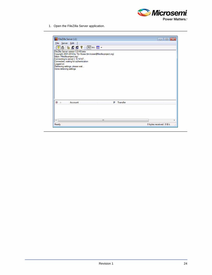
1. Open the FileZilla Server application.
Revision 1 24
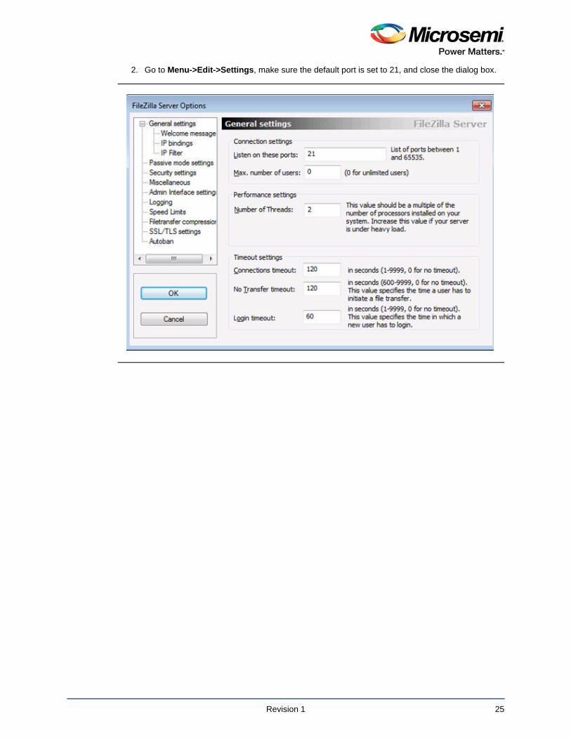
2. Go to Menu->Edit->Settings, make sure the default port is set to 21, and close the dialog box.
Revision 1 25

3. Open user settings: Menu->Edit->Users.
4. Click Add and enter the new user name, for example, "hsm".
5. Click OK.
Revision 1 26
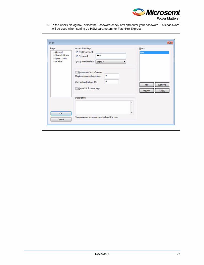
6. In the Users dialog box, select the Password check box and enter your password. This password will be used when setting up HSM parameters for FlashPro Express.
Revision 1 27
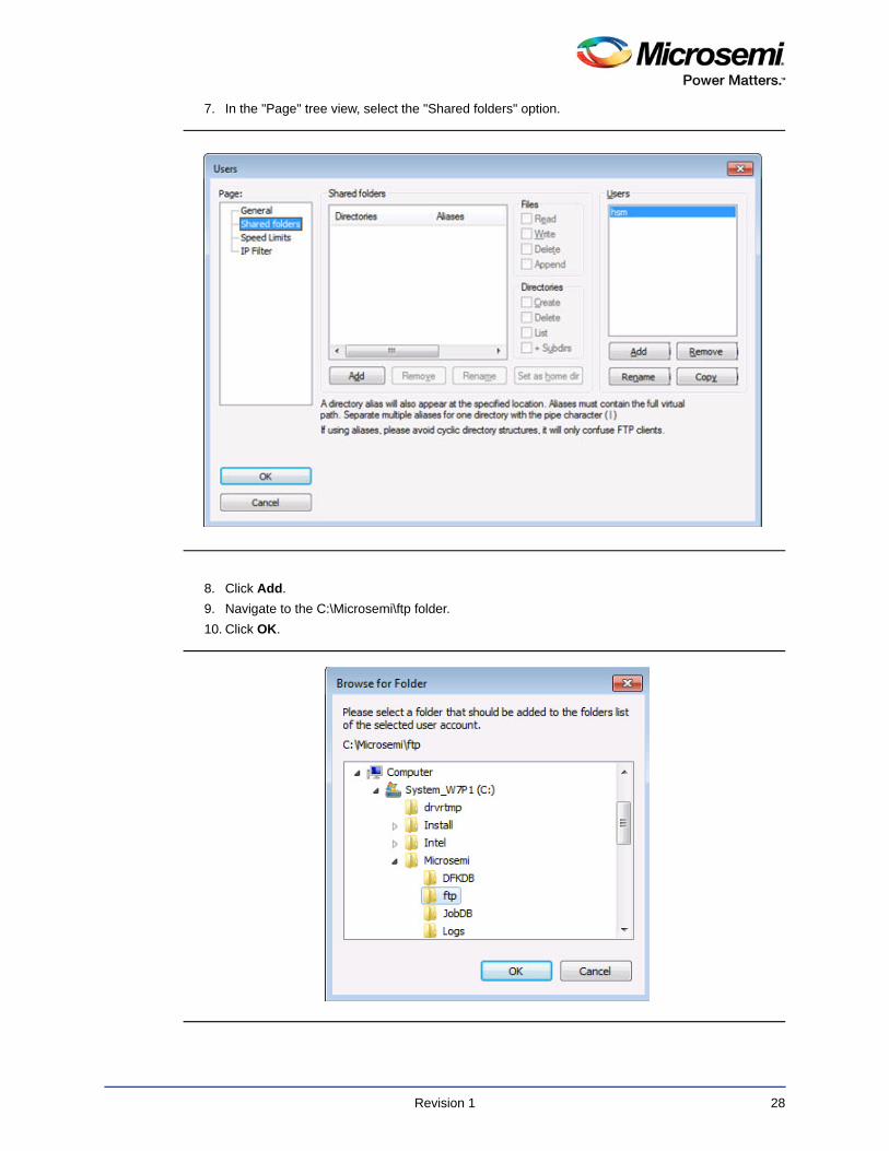
7. In the "Page" tree view, select the "Shared folders" option.
8. Click Add.
9. Navigate to the C:\Microsemi\ftp folder.
10. Click OK.
Revision 1 28
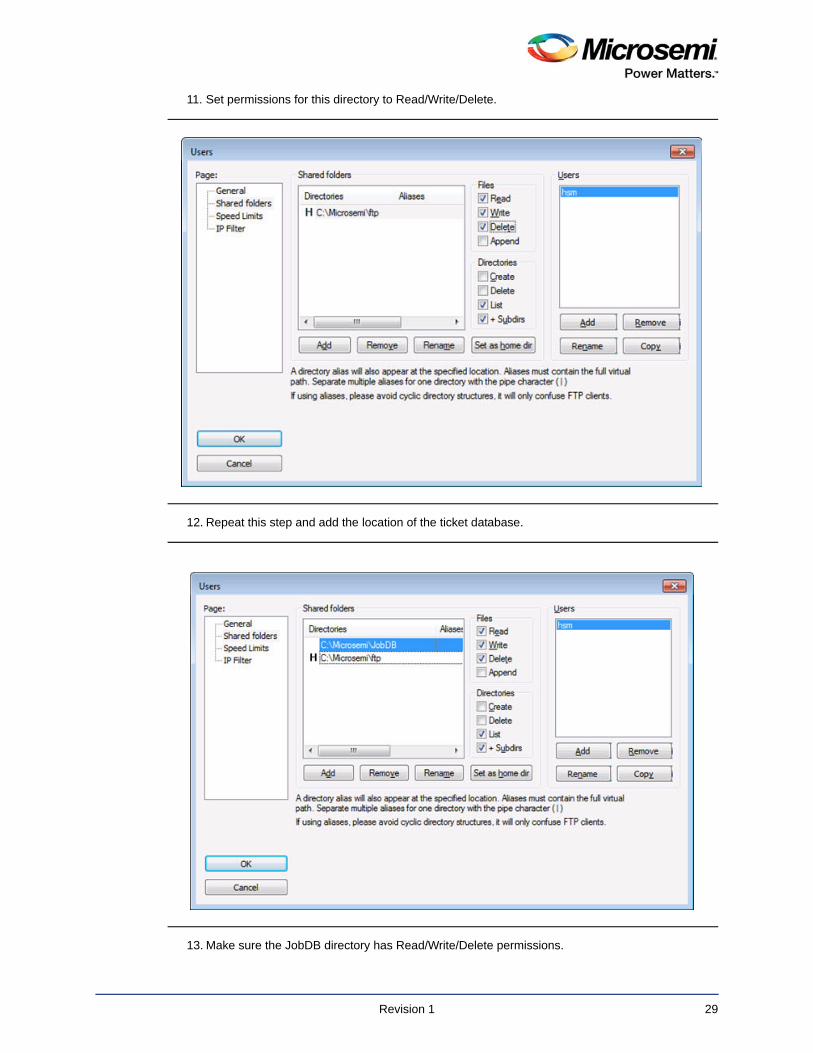
11. Set permissions for this directory to Read/Write/Delete.
12. Repeat this step and add the location of the ticket database.
13. Make sure the JobDB directory has Read/Write/Delete permissions.
Revision 1 29
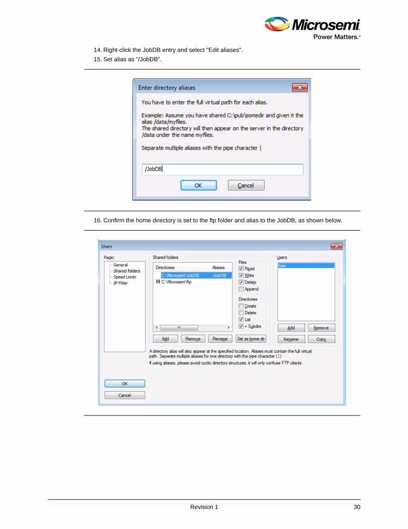
14. Right-click the JobDB entry and select "Edit aliases".
15. Set alias as "/JobDB".
16. Confirm the home directory is set to the ftp folder and alias to the JobDB, as shown below.
Revision 1 30
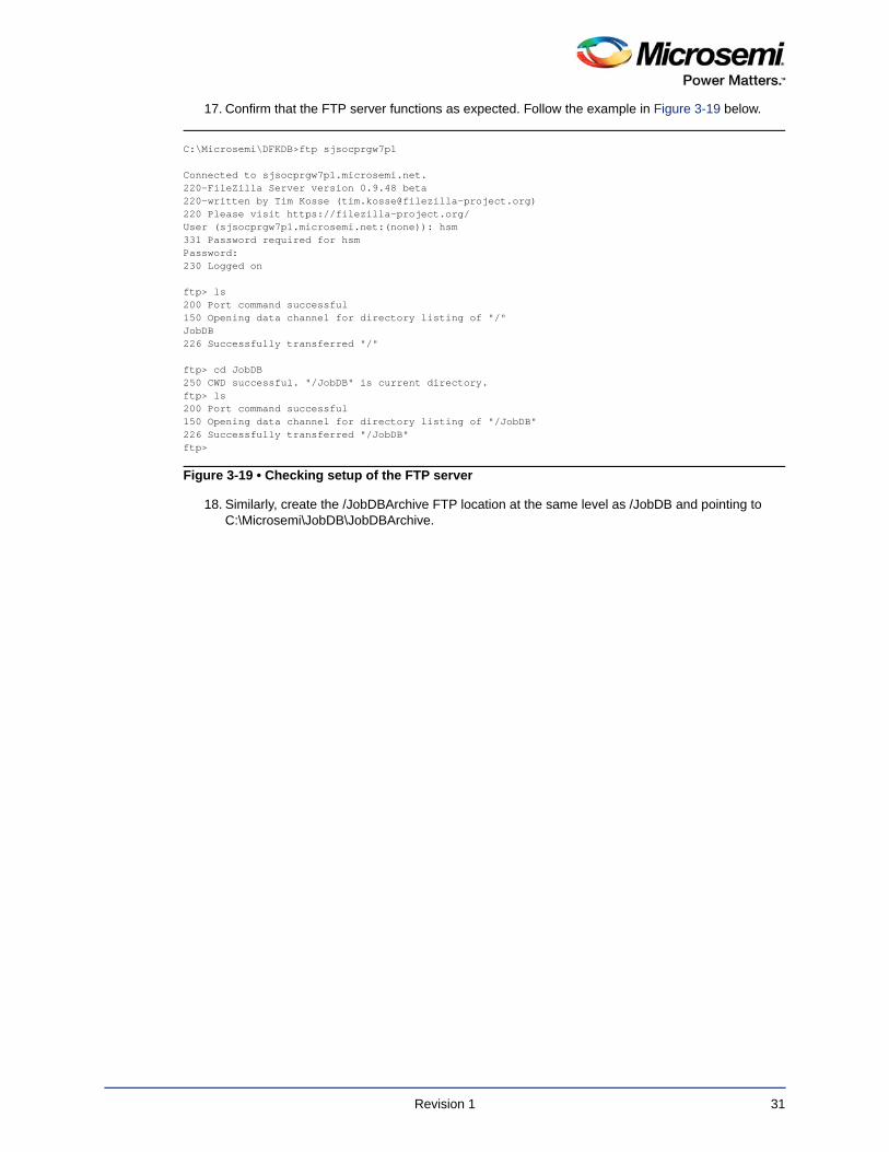
17. Confirm that the FTP server functions as expected. Follow the example in Figure 3-19 below.
18. Similarly, create the /JobDBArchive FTP location at the same level as /JobDB and pointing to C:\Microsemi\JobDB\JobDBArchive.
C:\Microsemi\DFKDB>ftp sjsocprgw7p1
Connected to sjsocprgw7p1.microsemi.net.220-FileZilla Server version 0.9.48 beta220-written by Tim Kosse ([email protected])220 Please visit https://filezilla-project.org/User (sjsocprgw7p1.microsemi.net:(none)): hsm331 Password required for hsmPassword:230 Logged on
ftp> ls200 Port command successful150 Opening data channel for directory listing of "/"JobDB226 Successfully transferred "/"
ftp> cd JobDB250 CWD successful. "/JobDB" is current directory.ftp> ls200 Port command successful150 Opening data channel for directory listing of "/JobDB"226 Successfully transferred "/JobDB"ftp>
Figure 3-19 • Checking setup of the FTP server
Revision 1 31
4 – M-HSM Reconfiguration and Post-Installation Actions
This chapter provides instructions for the setup and maintenance actions that can be performed on an installed and provisioned M-HSM.
HSM Module ReplacementNote: Only one module at a time can be connected to the M-HSM.
Overbuild Protection During Module MaintenanceNote: If the old module is removed or erased from the M-HSM, unfinished programming jobs will
not be able to proceed.
For any jobs in progress, certain ticket information is stored inside the NVRAM of the HW module, which makes job tickets physically uncloneable.
Module maintenance, such as replacement, firmware upgrades, and erase invalidate unfinished jobs. The user must submit a new job to continue manufacturing. However, issuing a new job without having a proof or termination of previous job(s) creates a potential threat of overbuilding. To minimize this risk, before undertaking such module maintenance actions, any active job(s) should be terminated using the complete_prog_job Tcl command (see the FlashPro Express User’s Guide). This job termination command will generate a Job End Certifier that can be validated on the U-HSM. This certifier is protected by the HSM and cannot be modified. It provides the user with assurance that further device programming is not possible from the old job. Once the Job End certifier has been validated by the user on the U-HSM, it is safe to issue a new job after maintenance has completed.
Remove the Old HSM ModulePhysically disconnect the old module. The M-HSM Security World contains a file with the module information. While this file can co-exist with the files for other modules added to the system, the user can choose to remove it for security reasons. The file is located in the Security World directory: %NFAST_KMDATA%\local directory. The file name follows the pattern "module_<module_ESN>". If needed, the user can also remove the licensing file from the Server and Tools directories: <M_UUID>.g4sl.
Set Up a New HSM ModuleAfter the module is installed on the system, it must be added to the Security World and set up to load SEE Machine firmware per module type.
Module Installation1. Install a new HSM module (see "HSM Hardware Module Installation" on page 10)
2. Install the Microsemi-issued HSM module license (see "Install HSM Module License File" on page 18)
3. Install the module warrant file (see "HSM Hardware Module Installation" on page 10)
Add the HSM Module to the Security WorldThe following steps require the Administrative Card Set (ACS). The number of required cards and their respective passphrases depend on the settings specified during Security World creation (see "Create the Security World" on page 14)
1. Set the module to the pre-init state.
Revision 1 31
2. Add the HSM module to the security world using the new-world command:
new-world --program --no-remoteshare-cert -m 1
3. Create a new NVRAM file (see "Create NVRAM-based Storage in the HSM Module" on page 17).
4. Set module to the operational state.
5. Set up the HSM module to load SEE Machine firmware: follow instructions in "Set Up the SEE Machine Firmware for Loading into the HSM Module" on page 19.
Import the Public Keys of the U-HSMFollow the instructions in "Import the U-HSM Public Keys" on page 22.
Export the Public Keys for Sending to a U-HSMFollow the instructions in "Export the M-HSM Public Keys" on page 21.
Import the New DFK DB and Manufacturing Keys from the U-HSM
Follow the instructions in "Import U-HSM Device Data" on page 22.
Upgrade the HSM Module FirmwareThis step shows how to upgrade HSM module firmware (not SEE Machine firmware). The firmware upgrade may be necessary in the following cases:
• The HSM module has a firmware revision that is not supported by the FlashProExpress version used (see M-HSM release notes for the supported revisions).
• The user wants to switch to another revision of Microsemi-supported firmware.
• Microsemi issues a security advisory.
Note: If the M-HSM has any active programming jobs, they will be disabled through the firmware upgrade. Also, the firmware upgrade will erase NVRAM and any information about module association with the Security World. Follow the steps below to upgrade the firmware of the HSM module and restore the HSM module on the M-HSM server:
1. Read the important notes in "Upgrade HSM Module Firmware" regarding the firmware upgrade procedure and firmware revisions compatibilities.
Note: If the firmware upgrade is initiated by a Microsemi security advisory, the instructions in the advisory shall supersede the instructions in this guide.
2. Terminate any active job(s) and forward job end certifier to the U-HSM.
Read important information regarding overbuild protection during HSM module maintenance operations in "Overbuild Protection During Module Maintenance" on page 31.
3. Upgrade the HSM module firmware.
HSM module firmware upgrade instructions are provided in "Upgrade HSM Module Firmware" on page 11.
4. Restore the module association with the Security World.
Follow the instructions in "Add the HSM Module to the Security World".
5. Start the M-HSM server.
Follow the instructions in "Start the M-HSM Server" on page 21 and confirm successful server startup.
6. Resubmit new programming jobs, if necessary.
Revision 1 32
Revision 1 33
5 – M-HSM Server Replication
An existing M-HSM server can be replicated to one or more new M-HSM servers. As a result, the replicated server gets a copy of the Security World, all HSM keys, imported public keys, the DFK DB, and manufacturing keys already existing on the source system.
Note: Programming jobs cannot be replicated, but they can be transferred. The overbuild protection does not allow cloning of any job that may exist in the source system. Job tickets reside inside the physical HSM module, and can only be transferred to the new system along with the physical module.
The following sections provide instructions for M-HSM server replication:
Install the SoftwareFollow the instructions in "Software Installation" on page 10 and install all required software packages.
Copy Over the Security World Copy the content of the Security World directory from the source to the destination machine. The location of the security world directory is: %NFAST_KMDATA%\local.
This step copies over the entire security environment:
• Security World data
• Created M-HSM keys
• Imported public keys
• Imported MFG keys
Copy Over the M-HSM Server1. Copy HSM server software components from the source HSM to the destination folder of the new
server (the default location is C:\Microsemi)
2. On the destination machine, delete the ticket db files (job cannot be replicated):
– C:\Microsemi\JobDB and
– C:\Microsemi\JobDB\JobDBArchive
Install a New HSM ModuleFollow the instructions in "Set Up a New HSM Module" on page 31.
Start the M-HSM ServerFollow the instructions in "Start the M-HSM Server" on page 21.
Set Up the FTP ServerFollow the instructions in "FTP Server Setup" on page 23.
A – Product Support
Microsemi SoC Products Group backs its products with various support services, including Customer Service, Customer Technical Support Center, a website, electronic mail, and worldwide sales offices. This appendix contains information about contacting Microsemi SoC Products Group and using these support services.
Customer ServiceContact Customer Service for non-technical product support, such as product pricing, product upgrades, update information, order status, and authorization.
From North America, call 800.262.1060From the rest of the world, call 650.318.4460Fax, from anywhere in the world, 650.318.8044
Customer Technical Support CenterMicrosemi SoC Products Group staffs its Customer Technical Support Center with highly skilled engineers who can help answer your hardware, software, and design questions about Microsemi SoC Products. The Customer Technical Support Center spends a great deal of time creating application notes, answers to common design cycle questions, documentation of known issues, and various FAQs. So, before you contact us, please visit our online resources. It is very likely we have already answered your questions.
Technical SupportFor Microsemi SoC Products Support, visit http://www.microsemi.com/products/fpga-soc/design-support/fpga-soc-support.
WebsiteYou can browse a variety of technical and non-technical information on the Microsemi SoC Products Group home page, at www.microsemi.com/soc.
Contacting the Customer Technical Support CenterHighly skilled engineers staff the Technical Support Center. The Technical Support Center can be contacted by email or through the Microsemi SoC Products Group website.
EmailYou can communicate your technical questions to our email address and receive answers back by email, fax, or phone. Also, if you have design problems, you can email your design files to receive assistance. We constantly monitor the email account throughout the day. When sending your request to us, please be sure to include your full name, company name, and your contact information for efficient processing of your request.
The technical support email address is [email protected].
Revision 1 34
MOCA
WOSaFa
E-
©2reloCosere
Microsemi makes no warranty, representation, or guarantee regarding the information contained herein orthe suitability of its products and services for any particular purpose, nor does Microsemi assume anyliability whatsoever arising out of the application or use of any product or circuit. The products soldhereunder and any other products sold by Microsemi have been subject to limited testing and should notbe used in conjunction with mission-critical equipment or applications. Any performance specifications arebelieved to be reliable but are not verified, and Buyer must conduct and complete all performance andother testing of the products, alone and together with, or installed in, any end-products. Buyer shall not relyon any data and performance specifications or parameters provided by Microsemi. It is the Buyer'sresponsibility to independently determine suitability of any products and to test and verify the same. Theinformation provided by Microsemi hereunder is provided "as is, where is" and with all faults, and the entirerisk associated with such information is entirely with the Buyer. Microsemi does not grant, explicitly orimplicitly, to any party any patent rights, licenses, or any other IP rights, whether with regard to such
About Microsemi
Microsemi Corporation (Nasdaq: MSCC) offers a comprehensive portfolio of semiconductorand system solutions for communications, defense & security, aerospace and industrialmarkets. Products include high-performance and radiation-hardened analog mixed-signalintegrated circuits, FPGAs, SoCs and ASICs; power management products; timing andsynchronization devices and precise time solutions, setting the world's standard for time; voiceprocessing devices; RF solutions; discrete components; Enterprise Storage andCommunication solutions, security technologies and scalable anti-tamper products; Ethernetsolutions; Power-over-Ethernet ICs and midspans; as well as custom design capabilities andservices. Microsemi is headquartered in Aliso Viejo, Calif. and has approximately 4,800employees globally. Learn more at www.microsemi.com.icrosemi Corporate Headquarters
ne Enterprise, Aliso Viejo, 92656 USA
ithin the USA: +1 (800) 713-4113 utside the USA: +1 (949) 380-6100les: +1 (949) 380-6136 x: +1 (949) 215-4996
mail: [email protected]
016 Microsemi Corporation. All rights served. Microsemi and the Microsemi go are trademarks of Microsemi rporation. All other trademarks and
My CasesMicrosemi SoC Products Group customers may submit and track technical cases online by going to My Cases.
Outside the U.S.Customers needing assistance outside the US time zones can either contact technical support via email ([email protected]) or contact a local sales office.
Visit About Us for sales office listings and corporate contacts.
Sales office listings can be found at www.microsemi.com/soc/company/contact/default.aspx.
ITAR Technical SupportFor technical support on RH and RT FPGAs that are regulated by International Traffic in Arms Regulations (ITAR), contact us via [email protected]. Alternatively, within My Cases, select Yes in the ITAR drop-down list. For a complete list of ITAR-regulated Microsemi FPGAs, visit the ITAR web page.
5-02-00707-1/09.16
information itself or anything described by such information. Information provided in this document isproprietary to Microsemi, and Microsemi reserves the right to make any changes to the information in thisdocument or to any products and services at any time without notice.
rvice marks are the property of their spective owners.