MANUFACTURE, PRE-ASSEMBLY, AND INSTALLATION OF ... · quality standards manufacture, pre-assembly,...
33
QUALITY STANDARDS MANUFACTURE, PRE-ASSEMBLY, AND INSTALLATION OF GEOMEMBRANES 2009 WATERSAVER COMPANY, INC. P.O. Box 16465 PH: (800) 525-2424 Denver, CO 80216-0465 (303) 289-1818 FX: (303) 287-3136 www.watersaver.com [email protected] An Equal Opportunity Employer
Transcript of MANUFACTURE, PRE-ASSEMBLY, AND INSTALLATION OF ... · quality standards manufacture, pre-assembly,...

QUALITY STANDARDS
MANUFACTURE, PRE-ASSEMBLY, AND INSTALLATION
OF
GEOMEMBRANES
2009
WATERSAVER COMPANY, INC.
P.O. Box 16465 PH: (800) 525-2424 Denver, CO 80216-0465 (303) 289-1818 FX: (303) 287-3136
www.watersaver.com [email protected]
An Equal Opportunity Employer
TABLE OF CONTENTS 1 GENERAL INFORMATION .................................................................. 4
1.1 PURPOSE ................................................................................................................................ 4 1.2 CONFORMANCE WITH PROJECT SPECIFICATIONS ......................................................... 4
2 GEOMEMBRANE MANUFACTURING ................................................ 4 2.1 RAW MATERIALS ................................................................................................................... 4 2.2 ROLL GOODS ......................................................................................................................... 4
3 GEOMEMBRANE FABRICATION ....................................................... 5 3.1 FACTORY FABRICATION ...................................................................................................... 5 3.2 IN-FACTORY SEAM TESTING ............................................................................................... 5 3.3 FACTORY SEAM REQUIREMENTS ...................................................................................... 5
4 PACKAGING, HANDLING, AND TRANSPORTATION ....................... 6 4.1 PACKAGING AND HANDLING .............................................................................................. 6 4.2 TRANSPORTATION................................................................................................................ 6
5 INSTALLATION ................................................................................... 6 5.1 ANCHORAGE SYSTEM .......................................................................................................... 6 5.2 SUBGRADE ............................................................................................................................. 7
5.2.1 Preparation ................................................................................................................ 7 5.2.2 Repair and Maintenance ........................................................................................... 7
5.3 GEOMEMBRANE PANEL PLACEMENT ............................................................................... 7 5.3.1 Panel Location........................................................................................................... 7 5.3.2 Weather Conditions .................................................................................................. 7 5.3.3 Geomembrane Panel Deployment .......................................................................... 7 5.3.4 Preparation for Seaming .......................................................................................... 8
5.4 FIELD SEAMING ..................................................................................................................... 8 5.4.1 Seam Preparation ..................................................................................................... 8
5.4.1.1 Repairs ........................................................................................................ 8 5.4.2 Chemical Fusion Field Seaming .............................................................................. 9 5.4.3 Cold Weather Chemical Fusion Field Seaming ..................................................... 9 5.4.4 Thermal Fusion Field Seaming (Continuous Width) ............................................. 9 5.4.5 Pipe Penetrations .................................................................................................... 10
5.5 LINING SYSTEM ACCEPTANCE ......................................................................................... 10 6 FIELD QUALITY ASSURANCE ......................................................... 10
6.1 OVERVIEW ............................................................................................................................ 10 6.2 TEST STRIP/TRIAL SEAMS ................................................................................................. 10 6.3 NON-DESTRUCTIVE SEAM TESTING ................................................................................ 11
6.3.1 Test Methods ........................................................................................................... 11 6.3.2 Remedial Action ...................................................................................................... 12
6.4 DESTRUCTIVE SEAM TESTING .......................................................................................... 12 6.4.1 Sampling Frequency ............................................................................................... 12 6.4.2 Sampling Procedure ............................................................................................... 12 6.4.3 Sample Geometry ................................................................................................... 12 6.4.4 Disposition of Samples .......................................................................................... 12 6.4.5 Sampling and Testing ............................................................................................. 13
6.4.5.1 Conditioning ............................................................................................. 13 6.4.5.2 Sampling ................................................................................................... 13 6.4.5.3 Testing ...................................................................................................... 13
6.4.6 Acceptance of Destructive Test Results .............................................................. 14 6.4.7 Remedial Action – Destructive Test Failure ......................................................... 14 6.4.8 Verification of Repairs ............................................................................................ 14 6.4.9 Deployment of Cover Soils over Geomembranes ............................................... 14

REFERENCES .................................................................................................................... 16 APPENDIX I PRODUCT SPECIFICATIONS .................................................................. 17 APPENDIX II NDT METHODS FOR FIELD SEAMS ....................................................... 26 APPENDIX III FIELD SEAM DETAIL ............................................................................... 28 APPENDIX IV SEAM REQUIREMENTS ........................................................................... 29 APPENDIX V RAW MATERIAL QUALIFICATIONS ......................................................... 30 APPENDIX VI PGI 1104 APPENDIX B ............................................................................. 31 APPENDIX VII ENHANCED TESTING INFO FOR REINFORCED GEOMEMBRANES .... 33

P.O. Box 16465 Denver, CO 80216 • PH 303-289-1818 • FX 303-287-3136 An Equal Opportunity Employer
4 QAQC MANUAL 01/09
1 GENERAL INFORMATION
1.1 PURPOSE
The purpose of this manual is to provide details of Manufacturing Quality Control (MQC), Manufacturing Quality Assurance (MQA), Construction Quality Control (CQC), and Construction Quality Assurance (CQA) for the manufacture, pre-assembly, and installation of geomembrane products supplied by Watersaver Company, Inc (WCI).
1.2 CONFORMANCE WITH PROJECT SPECIFICATIONS
It is the intent of WCI to comply with the generally recognized MQC, MQA, CQC and CQA standards and practices for governmental, manufacturing, pre-assembly and installing industries. If required, modification to this manual can be made via addendum in order to accommodate individual job specific requirements.
2 GEOMEMBRANE MANUFACTURING
2.1 RAW MATERIALS
WCI requires all manufacturers to certify that their sheeting is formulated and manufactured from 100% virgin raw materials that are specifically compounded for use in hydraulic structures. See Appendix V for additional raw material qualifications.
The manufacturers are required to submit written certification that each lot of material meets or exceeds WCI specifications located in Appendix I.
2.2 ROLL GOODS
All roll goods received from WCI suppliers are visually inspected for imperfections and contaminants. Manufacturer certifications show that physical property testing is conducted on each lot of roll goods. Materials tested must meet or exceed the values specified. The following properties are evaluated:
PROPERTY TEST METHOD TEST METHOD (Non-reinforced) (Reinforced) Thickness (inches, nominal) ASTM D751 ASTM D751
Breaking Factor (lbs/in) ASTM D882 ASTM D751
Elongation at Break (percent) ASTM D882 ASTM D751
Modulus @ 100% Elongation ASTM D882 N/A

P.O. Box 16465 Denver, CO 80216 • PH 303-289-1818 • FX 303-287-3136 An Equal Opportunity Employer
5 QAQC MANUAL 01/09
3 GEOMEMBRANE FABRICATION
3.1 FACTORY FABRICATION
Individual calendered widths (roll goods) are factory pre-assembled into large panels to minimize field seaming during installation.
Factory seams are produced using chemical, dielectric or thermal method. Each seaming method is tailored for optimum seam strength.
Nominal seam widtvhs, Non-reinforced 1” / Reinforced 1 ½” scrim to scrim.
Factory pre-assembly production records identify each panel by panel number, size, date of pre-assembly, material lot number and seam station identification. Each panel is prominently marked with the panel number and panel size to coincide with production records.
3.2 IN-FACTORY SEAM TESTING
Visual and non-destructive inspection is performed on 100% of factory pre-assembled seams, including ASTM D4545, through a combined use of sections 7.1.1 (OSHA limits) and 7.1.4. Every 50 l.f., factory seams are marked with: seam number, machine number, operator number and air lance/QC number. All factory seams are warranted for two (2) years.
In addition, WCI performs destructive testing on factory fabricated seams in order to verify quality compliance.
Destructive seam samples are taken at the beginning and end of each production shift. All seams are tested for compliance and the results are archived at the WCI facility. Test results are available upon request (job specific).
3.3 FACTORY SEAM REQUIREMENTS
All factory seams are tested for Bonded Seam and Peel strength in accordance with the appropriate (ASTM) standards. Specified values and test methods are listed in Appendix I.
Primary and secondary seaming methods are listed by material in Appendix IV.

P.O. Box 16465 Denver, CO 80216 • PH 303-289-1818 • FX 303-287-3136 An Equal Opportunity Employer
6 QAQC MANUAL 01/09
4 PACKAGING, HANDLING, AND TRANSPORTATION
4.1 PACKAGING AND HANDLING
After factory pre-assembly, the geomembrane panels are double accordion folded on a pallet or rolled on a cardboard core. Folded panels are shrink wrapped (light reflectant) using a water and UV resistant polymer sheeting with outer cardboard insert banded to a heavy duty wooden pallet. Rolled panels are wrapped in a protective layer and shrink wrapped (light reflectant). All pallets/rolls are identified by panel size, type, and number. Geomembrane panels delivered to the jobsite are unloaded on level ground, stored in their original, unopened containers in a secure, dry area, and protected from weathering. Whenever possible, a six-inch minimum air space between the pallets should be maintained, especially when the geomembrane panels are to be stored over an extended period of time. Pallets must not be stacked. Banding is not to be removed from the pallet until actual deployment, to insure stability.
Material Safety Data Sheets (MSDS) to be provided on all chemicals which include handling and personal protection during usage.
4.2 TRANSPORTATION
Transportation of the geomembrane will be arranged by WCI through an independent trucking firm, and will be shipped via a closed or flat bed trailer. Adequate tarps (flat bed) are recommended during transport. It is the responsibility of the receiver at the time of delivery to indicate condition of shipment on the Bill of Lading. Any visual damage MUST be noted in WRITING and WCI should be contacted within 24 hours or (extreme conditions) before accepting delivery.
5 INSTALLATION
5.1 ANCHORAGE SYSTEM
Unless otherwise specified, the anchor trench should be excavated by the earthwork contractor or others to the lines and grades shown on the design drawings. Store excavated material away from the area to be lined.
Complete trenching process prior to geomembrane placement.
A smooth transition surface from anchor trench to subgrade should be provided.
Following the completion of the seaming operation, the anchor trench shall be backfilled and compacted (as soon as possible) by the earthwork contractor to lock in the geomembrane. During ongoing backfilling operations, backfill should be kept a minimum of 10 feet from un-seamed areas.

P.O. Box 16465 Denver, CO 80216 • PH 303-289-1818 • FX 303-287-3136 An Equal Opportunity Employer
7 QAQC MANUAL 01/09
5.2 SUBGRADE
5.2.1 Preparation
Surfaces to be lined shall be smooth and free of all rocks, stones, roots, sharp objects, or debris of any kind. No stones or other hard objects that will not pass through a 3/8” screen shall be present in the top 1” of the surfaces to be covered. The surface shall provide a firm, unyielding foundation for the membrane with no sudden, sharp or abrupt changes or break in grade.
If an herbicide is required, it must be suitable for use with geomembranes and shall be applied as per the manufacturer recommendations. Suitability for use with the geomembrane shall be confirmed by the herbicide manufacturer.
5.2.2 Repair and Maintenance
Prior to geomembrane installation, the surfaces to be lined shall be inspected for
acceptability by the installers. Any necessary repairs will be made by the owner or earthwork contractor. It is the responsibility of the owner or earthwork contractor to maintain the integrity of the subgrade prior to, and during the geomembrane installation. This includes the control of ground water in the area to be lined.
5.3 GEOMEMBRANE PANEL PLACEMENT
5.3.1 Panel Location
Install the geomembrane as indicated in the approved layout drawing. The installer
may modify the proposed layout to best meet the intent of the project specification and/or to accommodate existing site conditions.
5.3.2 Weather Conditions
Consideration must be given to low temperature (<40°F) handling characteristics of the geomembrane before installation, in some cases, before the liner is actually ordered. Please contact Watersaver Company, Inc. if the above condition exists.
5.3.3 Geomembrane Panel Deployment
The number of panels to be deployed in any day shall be limited to the number of panels which can be seamed or secured that day.
The geomembrane shall be installed in a relaxed manner and free of tension and stress. In areas where grade transitions occur, “bridging” or “trampolining” of the geomembrane shall not be allowed. To accommodate grade transition, adequate slack is necessary. Wrinkling of the geomembrane is acceptable and indicates proper slack consideration.
Deploy geomembrane panels to meet a minimum panel overlap of six inches. During cold weather deployment, consideration must be given to residual packaging geometry (ability to lay flat) as it relates to installation quantity. Shingle all panels in the down gradient direction whenever possible.
P.O. Box 16465 Denver, CO 80216 • PH 303-289-1818 • FX 303-287-3136 An Equal Opportunity Employer
8 QAQC MANUAL 01/09
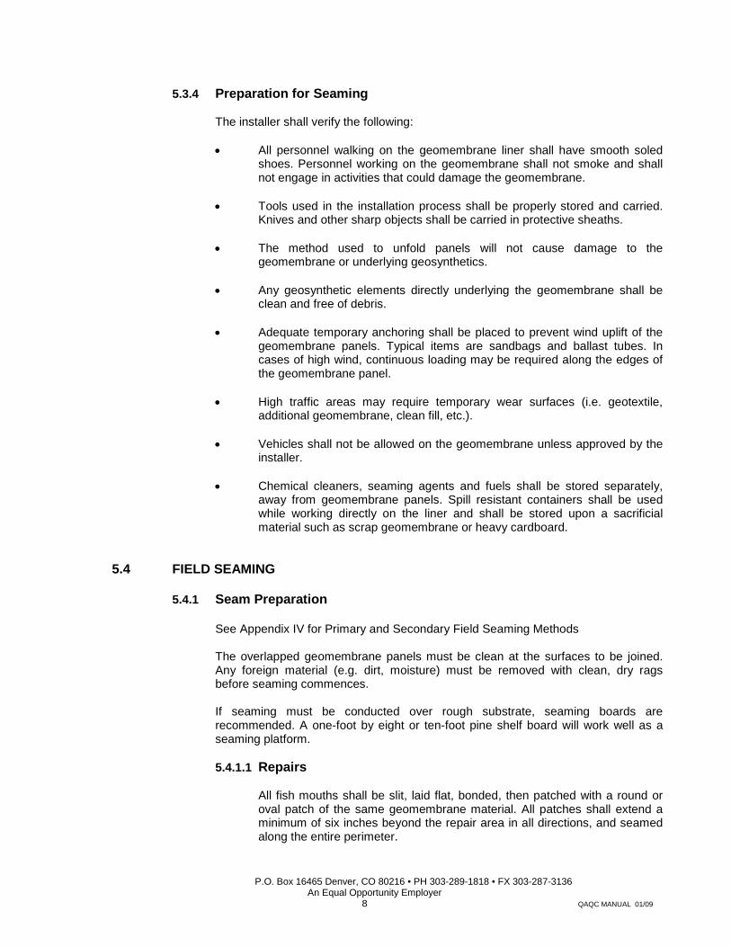
5.3.4 Preparation for Seaming
The installer shall verify the following:
• All personnel walking on the geomembrane liner shall have smooth soled shoes. Personnel working on the geomembrane shall not smoke and shall not engage in activities that could damage the geomembrane.
• Tools used in the installation process shall be properly stored and carried.
Knives and other sharp objects shall be carried in protective sheaths.
• The method used to unfold panels will not cause damage to the geomembrane or underlying geosynthetics.
• Any geosynthetic elements directly underlying the geomembrane shall be
clean and free of debris.
• Adequate temporary anchoring shall be placed to prevent wind uplift of the geomembrane panels. Typical items are sandbags and ballast tubes. In cases of high wind, continuous loading may be required along the edges of the geomembrane panel.
• High traffic areas may require temporary wear surfaces (i.e. geotextile,
additional geomembrane, clean fill, etc.).
• Vehicles shall not be allowed on the geomembrane unless approved by the installer.
• Chemical cleaners, seaming agents and fuels shall be stored separately,
away from geomembrane panels. Spill resistant containers shall be used while working directly on the liner and shall be stored upon a sacrificial material such as scrap geomembrane or heavy cardboard.
5.4 FIELD SEAMING
5.4.1 Seam Preparation
See Appendix IV for Primary and Secondary Field Seaming Methods
The overlapped geomembrane panels must be clean at the surfaces to be joined. Any foreign material (e.g. dirt, moisture) must be removed with clean, dry rags before seaming commences.
If seaming must be conducted over rough substrate, seaming boards are
recommended. A one-foot by eight or ten-foot pine shelf board will work well as a seaming platform.
5.4.1.1 Repairs
All fish mouths shall be slit, laid flat, bonded, then patched with a round or
oval patch of the same geomembrane material. All patches shall extend a minimum of six inches beyond the repair area in all directions, and seamed along the entire perimeter.
P.O. Box 16465 Denver, CO 80216 • PH 303-289-1818 • FX 303-287-3136 An Equal Opportunity Employer
9 QAQC MANUAL 01/09
5.4.2 Chemical Fusion Field Seaming
Chemical fusion agent shall be applied between the two surfaces to be joined. These surfaces shall be mated together and pressure applied to the upper surface by means of a roller (high durometer rubber, nylon, or steel).
A sufficient amount of chemical fusion agent shall be applied between the two
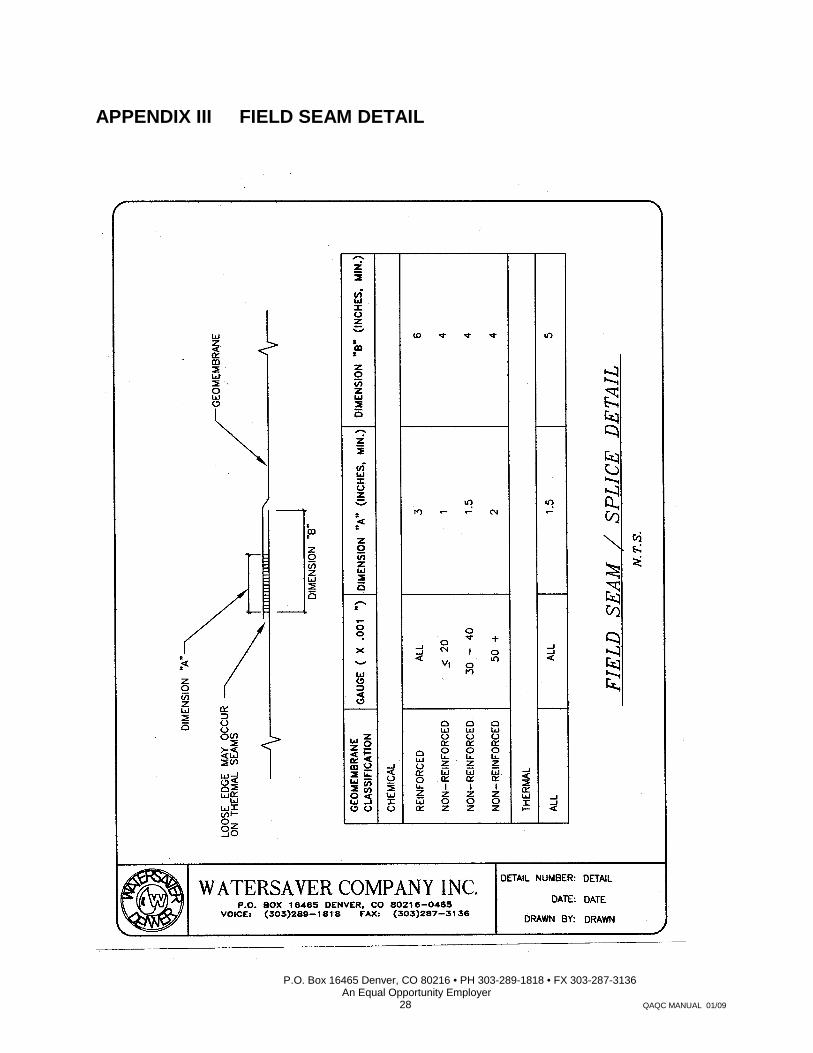
geomembrane surfaces to be joined so when rolled, a thin excess of agent will be forced out of the seam. Any excess chemical agent shall be wiped from the geomembrane. The lower of the two surfaces to be joined shall be completely wet by the chemical fusion agent. See Field Seam Geometry Table in Appendix III.
If any discontinuities are noted, allow approximately ½ hour before reapplying agent.
This process can be expedited by using artificial heat.
5.4.3 Cold Weather Chemical Fusion Field Seaming
Generally for cold weather seaming, when the geomembrane surface is below 50°F, the surfaces to be joined must be preheated.
If the soil beneath the geomembrane is frozen, the application of heat to the area to
be seamed may result in moisture condensing between the surfaces to be joined. This condition may be eliminated by placing a seaming board, or slip-sheet made from the same geomembrane material, between the frozen surface and the geomembrane to be seamed.
See Field Seam Geometry Table in Appendix III.
5.4.4 Thermal Fusion Field Seaming (Continuous Width) The two most common seaming methods are Hot Wedge and Hot Air. Either method
is capable of producing a quality seam. These units are equipped with speed and temperature controls with digital (LED) readout along with pressure adjustment.
• Thin gauge materials (<30 Mil) combined with high ambient temperatures
can affect seam quality.
• Hand Held Leister or equal can be used for pipe boots, details and patching for the majority of non-crystalline geomembranes.
• Each method must be capable of producing sufficient amount of controlled
heat and pressure applied to the seam overlap contact zone, resulting in a continuous thermal weld.
• Pressure squeeze out along seam edge to be kept to a minimum in order to
maximize overall seam thickness.
• Exercise caution when operating welder in direct contact with subgrade. Drive (pressure) rollers must be kept clean at all times.

P.O. Box 16465 Denver, CO 80216 • PH 303-289-1818 • FX 303-287-3136 An Equal Opportunity Employer
10 QAQC MANUAL 01/09
5.4.5 Pipe Penetrations Penetrations are sealed via the use of WCI factory fabricated pipe seals. Pipe seals
are thermally constructed using the same material as the specified geomembrane. For reinforced material, the tube section of the pipe seal can be constructed using non-reinforced parent material. The method of bonding is as outlined in the field seaming section.
5.5 LINING SYSTEM ACCEPTANCE
The installer shall retain responsibility for the geomembrane installation until acceptance by the Engineer and/or Owner.
The geomembrane liner installation will be accepted by the Owner when the following conditions have been met:
1. Installation of the geomembrane is complete.
2. Verification of the integrity of all seams and repairs, as required by the
specifications, is complete.
3. All documentation pertaining to the geomembrane installation is completed and submitted to the Owner/Engineer.
6 FIELD QUALITY ASSURANCE
6.1 OVERVIEW
Field seam quality shall be demonstrated by non-destructive (NDT) and destructive (DT) test methods.
The primary purpose of the NDT method is to demonstrate continuity along the entire length and to validate 100% of the field seam. NDT methodology is described in section 6.3 below.
The purpose of the DT method is to determine the quality of a given seam by removing a representative seam sample, and testing the given sample for compliance with accepted applicable industry standards. Testing may be conducted either at the job site, or at a remote testing laboratory. DT methodology is discussed in section 6.4 below.
6.2 TEST STRIP/TRIAL SEAMS
A general requirement of most CQA Documents is that “test seams” or “test strips” be made on a periodic basis. Test strips generally reflect the quality of field seams but should never be used solely for the final field seam acceptance. Final field seam acceptance requirements should be specified in the contract specification and should include a minimum level of destructive testing of the field seams. Test strips are made to minimize the amount of destructive sampling/testing on the finished panels. Typically these test seams, for each seaming crew, are made once per day, or every time equipment is changed, or if significant changes in site conditions are noted, or as required in the contract specification. The purpose of these tests is to establish that proper seaming materials, temperatures, pressures, rates, and techniques along with the necessary geomembrane pre-seaming preparation are being accomplished. Test strips may be used for CQA/CQC evaluation, and must be of sufficient size in order to conduct required testing.

P.O. Box 16465 Denver, CO 80216 • PH 303-289-1818 • FX 303-287-3136 An Equal Opportunity Employer
11 QAQC MANUAL 01/09
While cursory test seams are evaluated, the seaming crew may begin and continue to work as long as the field seam being constructed is completely traceable and identifiable. If a test seam fails to meet the field seam design specification, then an additional test seam sample is constructed and re-tested by the same seaming crew, equipment, and materials.
Field seams will not be accepted unless CQC seam test result criteria as per the design specification are met.
One of the following procedures shall apply whenever a sample fails a destructive test:
1. The field seam shall be reconstructed between two test locations shown to have
acceptable results; one located on either side of the failed sample.
2. The seam shall be traced outward to intermediate points (a maximum of 10 feet from the failed sample in each direction) and sampled for additional testing. If the samples are found to provide acceptable test results, the seam is reconstructed between these two sample locations. If an intermediate sample fails, the process is repeated to establish the zone in which the seam is to be reconstructed. All reconstructed seams shall be defined by two locations from which samples passing other destructive tests have been taken.
Reconstruction of field seams shall be accomplished by removing the suspect seam, repositioning panels and re-seaming, or by installing a cap strip to cover the seam under reconstruction. Cap stripping shall extend a minimum of six inches beyond the reconstructed seam in all directions.
For geomembrane seams that are bonded by the chemical fusion method, the seams must be cured prior to testing. Without the application of heat, the cure times can range from a few hours to a few days. Accelerated curing for on site CQC testing requires the use of an oven or other suitable heat source to condition the seam samples from 1 to 16 hours in a temperature range of 122°F to 158°F. Following the accelerated cure period, a post-cure conditioning period of at least ½ hour at ambient conditions prior to testing is required.
During the CQC and CQA test requirement periods, a liner should not be covered, and it cannot be placed into service. This will insure the ease of repairing or reconstructing in the event it is required. During this period, it is imperative that the liner be properly ballasted and otherwise secured so as to prevent wind or unusual weather damage.
6.3 NON-DESTRUCTIVE SEAM TESTING
6.3.1 Test Methods
The following test methods are acceptable for non-destructive testing of field seams:
A. Air Lance B. Vacuum Chamber
See Appendix II for application of these methods based on seam type or location.
Testing Reference Refer to ASTM D 4437-8

P.O. Box 16465 Denver, CO 80216 • PH 303-289-1818 • FX 303-287-3136 An Equal Opportunity Employer
12 QAQC MANUAL 01/09
6.3.2 Remedial Action
If unbonded areas are located, they can often be repaired by using detail method 5.4
or 5.4.1.1. All patches shall extend a minimum of six inches beyond the area in all directions.
6.4 DESTRUCTIVE SEAM TESTING
6.4.1 Sampling Frequency
Destructive seam testing can be conducted along completed field seams at intervals of 1000 feet (or at intervals indicated in the project specification, and as addressed by addendum to this document). Wherever possible, test strips should be taken out of the anchor trenches so as not to disturb the integrity of the functional lining system.
6.4.2 Sampling Procedure
Samples shall be removed from the completed geomembrane seam by the installer. The sample shall be labeled in a clear and logical manner. The sample location must be identified and recorded.
Any holes in the geomembrane resulting from destructive seam sampling shall be
immediately repaired by patching the sampled area with identical geomembrane material. The patch must extend a minimum of six inches beyond the repair area in all directions. The continuity of repaired sampling locations shall be confirmed via NDT methods described above.
6.4.3 Sample Geometry
The minimum sample geometry shall be as follows:
Sample width shall be determined as the width of the field seam plus six inches on both sides of the seam.
Sample length can be up to forty-eight (48”) inches for non-reinforced material and
can be up to one hundred four (104”) inches for reinforced material.
See Appendix III for seam diagram.
6.4.4 Disposition of Samples
The sample described above shall be cut into three equal segments. One segment of the sample shall be submitted for laboratory (or field) testing; one segment to the installer, and the remaining segment to the owner.

P.O. Box 16465 Denver, CO 80216 • PH 303-289-1818 • FX 303-287-3136 An Equal Opportunity Employer
13 QAQC MANUAL 01/09
6.4.5 Sampling and Testing
6.4.5.1 Conditioning Conditioning of all samples prior to testing is imperative. Field seams
produced using a chemical fusion agent must be allowed to cure until the required strength values can be achieved. *Accelerated curing can be accomplished by conditioning the samples at temperature of 122°F-158°F for sixteen hours. Following the accelerated cure period, a post-cure conditioning period of at least ½ hour at ambient conditions prior to testing is required. *Ref: EPA/530/SW-91-051-5/91
Chemical seam samples shall be considered ready for testing when
the chemical fusion agent odor is no longer detectable.
6.4.5.2 Sampling
Test specimens shall be prepared as per Section 6.4.3.
6.4.5.3 Testing
Specimens shall be tested in order to determine bonded seam strength and peel adhesion. Testing Methods per ASTM procedures indicated by Appendix I.
A. Bonded Seam Strength (ASTM D882)
Non-reinforced Material
Specimen dimensions shall be one inch in width and shall extend a
distance of four inches (4”) on both sides of field seam. Samples must be cut in a manner which eliminates nicks or tears in the specimen which could cause premature failure (refer to ASTM D882 for further information). Specimens must be cut so that the long dimension of the specimen is perpendicular to the length of the seamed sample.
Reinforced Material (ASTM D751)
Specimen dimensions shall be four inches (4”) in width and shall
extend a distance of four and one-half (4-1/2”) on both sides of field seam. Samples must be cut in a manner which eliminates nicks or tears in the specimen which could cause premature failure (refer to ASTM D882 for further information). Specimens must be cut so that the long dimension of the specimen is perpendicular to the length of the seamed sample.
B. Peel Adhesion (ASTM D882)
Non-reinforced and reinforced material.
Prepare specimens as described above for bonded seam strength.

P.O. Box 16465 Denver, CO 80216 • PH 303-289-1818 • FX 303-287-3136 An Equal Opportunity Employer
14 QAQC MANUAL 01/09
C. Quantity of Specimens
A total of ten specimens shall be cut from the sample. Five specimens will be used to perform bonded seam strength testing with the remaining five specimens to be used for peel adhesion testing. Details of the test procedures are outlined in ASTM D751, Modified (Bonded Seam Strength), and ASTM D413, Modified (Peel Adhesion). Specimens to be selected (cut) alternately from samples (i.e. peel, shear, peel).
6.4.6 Acceptance of Destructive Test Results
See Appendix I for minimum specified seam strength values.
6.4.7 Remedial Action – Destructive Test Failure
One of the following procedures shall apply whenever a sample fails a destructive test:
1. The field seam shall be reconstructed between two test locations shown to
have acceptable results; one located on either side of the failed sample.
2. The seam shall be traced outward to intermediate points (a maximum of 10 feet from the failed sample in each direction) and sampled for additional testing. If the samples are found to provide acceptable test results, the seam is reconstructed between these two sample locations. If an intermediate sample fails, the process is repeated to establish the zone in which the seam is to be reconstructed. All reconstructed seams shall be defined by two locations from which samples passing other destructive tests have been taken.
Reconstruction of field seams shall be accomplished by either removing the suspect
seam, repositioning panels and re-seaming, or by installing a cap strip to cover the seam under reconstruction. Cap stripping shall extend a minimum of six inches beyond the reconstructed seam in all directions.
6.4.8 Verification of Repairs
Any repair requiring a patch or cap strip shall be identified on the as-built drawing. Each repair shall undergo non-destructive testing as described in section 6.3 above. Repairs which pass the NDT shall be taken as an indication of proper repair. Failed NDT’s will result in reconstruction and re-testing of the repair area until a passing result is obtained.
6.4.9 Deployment of Cover Soils over Geomembranes Cover soils deployed over synthetic liners should be free of all sharp objects-sharp
rocks, and sharp sticks. The stones present in the soil shall be rounded and smooth and no larger than ¾ inch in diameter.

P.O. Box 16465 Denver, CO 80216 • PH 303-289-1818 • FX 303-287-3136 An Equal Opportunity Employer
15 QAQC MANUAL 01/09
Cover materials should be deployed using bulldozers separated from the membrane
by at least one foot of cover soil for the smallest size dozers, and at least 18 inches of cover soil separation for the larger size dozers. The spreading operation should begin with placement of a mound of soil such that as the dirt covers the liner, it must ascend up the mount and then down the mound suppressing the formation of wrinkles. The movement of the soil must have this vertical decent to it as the dirt is spread over the membrane, rather than be pushed horizontally across the membrane. This type of action will suppress the formation of wrinkles in the path of the cover soil as it is being spread over the membrane and avoid burying the wrinkles in the liner. Alternatively, a front-end loader can be used to place the cover soil out ahead of the path of the dozer to minimize spreading of the dirt and suppress wrinkle formation. If these procedures are followed, there should be no threat of puncture to the membrane due to cover soil operations, and buried wrinkles should be minimized.

P.O. Box 16465 Denver, CO 80216 • PH 303-289-1818 • FX 303-287-3136 An Equal Opportunity Employer
16 QAQC MANUAL 01/09
REFERENCES ENVIRONMENTAL PROTECTION AGENCY (EPA) Lining for Waste Containment and Other Impoundment Facilities EPA/600/2-88/052 Inspection Techniques for the Fabrication of Geomembrane Field Seams EPA/530/SW-91/051 – 5/91 AMERICAN SOCIETY FOR TESTING AND MATERIALS NATIONAL SANITATION FOUNDATION (NSF) Joint Committee on Flexible Membrane Liners Standard 54-1991 PVC Geomembrane Institute ASTM Committee D – 35.10
P.O. Box 16465 Denver, CO 80216 • PH 303-289-1818 • FX 303-287-3136 An Equal Opportunity Employer
17 QAQC MANUAL 01/09
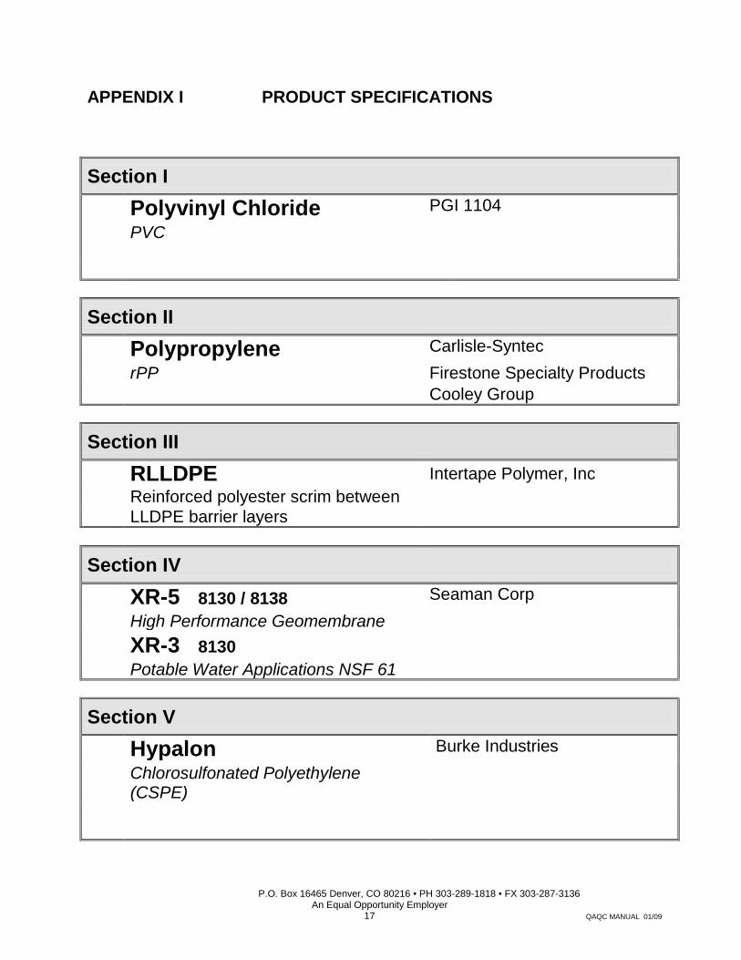
APPENDIX I PRODUCT SPECIFICATIONS
Section I
Polyvinyl Chloride PGI 1104 PVC
Section II
Polypropylene Carlisle-Syntec rPP Firestone Specialty Products Cooley Group
Section III
RLLDPE Intertape Polymer, Inc Reinforced polyester scrim between LLDPE barrier layers
Section IV
XR-5 8130 / 8138 Seaman Corp High Performance Geomembrane
XR-3 8130
Potable Water Applications NSF 61
Section V
Hypalon Burke Industries Chlorosulfonated Polyethylene (CSPE)

APPENDIX 1 – SECTION 1
P.O. Box 16465 Denver, CO 80216 • PH 303-289-1818 • FX 303-287-3136 An Equal Opportunity Employer
18 QAQC MANUAL 01/09
WATERSAVER PVC
GEOMEMBRANE LINER ENGINEERING SPECIFICATION GUIDE
POLYVINYL CHLORIDE (PVC)
PROPERTIES TEST METHOD SPECIFIED VALUES
Thickness ASTM D 5199 20 ± 1 mil
0.51 ± 0.03 mm 30 ± 1.5 mil
.76 ± .04 mm 40 ± 2 mil
1.02 ± .05 mm 50 ± 2.5 mil
1.27 ± .06 mm 60 ± 3 mils
1.52 ± .08 mm
Tensile Properties Strength at Break
ASTM D 882 Min
48 lbs/in 8.4 kN/m
73 lbs/in
12.8 kN/m
97 lbs/in
17.0 kN/m
116 lbs/in 20.3 kN/m
137 lbs/in 24.0 kN/m
Elongation
360% 380% 430% 430% 450%
Modulus @ 100% 21 lbs/in
3.7 kN/m 32 lbs/in 5.6 kN/m
40 lbs/in 7.0 kN/m
50 lbs/in 8.8 kN/m
60 lbs/in 10.5 kN/m
Tear Strength ASTM D 1004 Min.
6 lbs 27 N
8 lbs 35 N
10 lbs 44 N
13 lbs 58 N
15 lbs 67 N
Dimensional Stability ASTM D 1204 Max Chg 4% 3% 3% 3% 3%
Low Temperature Impact
ASTM D 1790 Pass
-15ºF -26ºC
-20ºF -29 ºC
-20ºF -29ºC
-20ºF -29ºC
-20ºF -29ºC
Index Properties
Specific Gravity ASTM D 792 Typical 1.2 g/cc 1.2 g/cc 1.2 g/cc 1.2 g/cc 1.2 g/cc
Water Extraction % loss (max.)
ASTM D 1239 Max Loss 0.15% 0.15% 0.20% 0.20% 0.20%
Average Plasticizer Molecular Weight ASTM D 2124 400 400 400 400 400
Volatility Loss ASTM D 1203 Max Loss 0.9% 0.7% 0.5% 0.5% 0.5%
Soil Burial Break Strength Elongation Modulus at 100%
G160 Max Chg
5%
20% 20%
5%
20% 20%
5%
20% 20%
5%
20% 20%
5%
20% 20%
Hydrostatic Resistance ASTM D 751 Min.
68 psi 470 kPa
100 psi 690 kPa
120 psi 830 kPa
150 psi 1030 kPa
180 psi
Seam Strengths
Shear Strength Peel Strength
ASTM D 882 Min ASTM D-882 Min
38.4 lbs/in 6.7 kN/m
12.5 lbs/in 2.2 kN/m
58.4 lbs/in 10 kN/m
15 lbs/in 2.6 kN/m
77.6 lbs/in 14 kN/m
15 lbs/in 2.6 kN/m
92.8 lbs/in 16 kN/m
15 lbs/in 2.6 kN/m
109.6 lbs/in 20 kN/m
15 lbs/in 2.6 kN/m
The information contained herein is offered free of charge, and is, to our best knowledge, true and accurate; however, all recommendations or suggestions are made without guarantee, since the conditions of use are beyond our control. There is no expressed warranty and no implied warranty of merchantability or of fitness for purpose of the product or products described herein. In submitting this information, no liability is assumed or license or other rights implied given with respect to any existing or pending patent, patent applications or trademarks. The observance of all legal regulations and patents is the responsibility of the user.

APPENDIX 1 – SECTION 2
P.O. Box 16465 Denver, CO 80216 • PH 303-289-1818 • FX 303-287-3136 An Equal Opportunity Employer
19 QAQC MANUAL 01/09
WATERSAVER rPP
GEOMEMBRANE LINER ENGINEERING SPECIFICATION GUIDE
POLYPROPYLENE Reinforced Geomembrane
PROPERTY TEST METHOD SPECIFIED VALUES
Property of Unaged Sheet
Property After Aging 672 hrs (28 days @
240ºF (116°C)
Tolerance on nominal thickness, % ASTM D 5199 36 mil (0.91mm) ± 10 45 mil (1.14 mm) ± 10 60 mil (1.52 mm) ± 10
Thickness over scrim, in (mm) 36-mil (0.91 mm) 45-mil (1.14 mm) 60-mil (1.52 mm)
ASTM D 4637 Optical Method
0.010 (0.254) min. 0.013 (0.330) min. 0.030 (0.762) min.
Mass per unit area, lb/ft2 (g/ft2) (kg/m2) 36-mil (0.91 mm) 45-mil (1.14 mm) 60-mil (1.52 mm)
ASTM D 5261
0.17 (77) (0.83) typical 0.21 (95) (1.03) typical 0.25 (117) (1.22) typical
Breaking strength, lbf (kN) (grab tensile at strain rate of 12 in./min.) 36-mil (0.91 mm, 45 mil (1.14 mm) & 60-mil (1.52 mm)
ASTM D 7004
200 (0.9) min. 260 typ. 250 (1.1) min. 300 typ.
200 (0.9) min. 260 typ. 250 (1.1) min. 300 typ.
Elongation at break of fabric, % ASTM D 7004 25 typical 25 typical Tearing strength, lbf (N) (2 in/min strain rate) 36-mil (0.91mm), 45 mil (1.14mm) & 60-mil (1.52mm)
ASTM D 5884 (max. load)
80 (356) min 130 (578) typ. 100 (445) typ. 160 (712) typ.
Low temperature flexibility, ºF (ºC) ASTM D2136
1/8 in mandrel 4 hour @ Temp.)
-40 (-40) max. -50 (-46) typical
Linear Dimensional Change (shrinkage), % 6 h @ 158°F (70°C) or 1 hr @ 212°F (100°C) ASTM D 1204 ± 1.0 max. - 0.5 typical
Ozone resistance, 100 pphm, 168 hrs ASTM D 1149 No cracks No cracks Resistance to water (distilled) absorption After 30 days immersion 122ºF (50ºC) Change in mass, %
ASTM D 471 (coating compound only)
1.0 max. 0.5 typical
Hydrostatic resistance, lbf/in2 or psi (MPa) (Mullen burst) 36-mil (0.91 mm) 45-mil (1.14 mm) 60-mil (1.52 mm)
ASTM D 751 Procedure A
350 (2.4) min
400 (2.8) typical 450 (3.1) typical 500 (3.4) typical
350 (2.4) min
400 (2.8) typical 450 (3.1) typical 500 (3.1) typical
Field seam strength, lbf/in. (kN/m) Seam tested in peel after weld
ASTM D 413 1 in. wide
22 (3.9) min. 45 (7.9) typical peak load
Water vapor permeance, Perms ASTM E 96 0.10 max. 0.05 typical Puncture resistance, lbs (N) 36-mil (0.91 mm) 45-mil (1.14 mm) 60-mil (1.52 mm)
ASTM D 4833 (index puncture)
85 (378) min. 110 (489) typical 120 (534) typical 118 (525) typical
Resistance to xenon-arc weathering1 Xenon-Arc, 10,080 kJ/m2 total radiant exposure, visual condition at 10X
ASTM G 155 0.70 W/m2
80ºC B.P.T.
No cracks No loss of breaking or tearing strength
Potable Water Accepted NSF-61 Passes
Chronic Toxicity Screening EPA/600/4-89/001
ASTM E-729 Method 1000.0
Passes Passes
1 Approximately equivalent to 8000 hours exposure at 0.35 W/m2 irradiance B.P.T. is black panel temperature. 2 Factory bonded seam strength is the responsibility of the fabricator.
The information contained herein is offered free of charge, and is, to our best knowledge, true and accurate; however, all recommendations or suggestions are made without guarantee, since the conditions of use are beyond our control. There is no expressed warranty and no implied warranty of merchantability or of fitness for purpose of the product or products described herein. In submitting this information, no liability is assumed or license or other rights implied given with respect to any existing or pending patent, patent applications or trademarks. The observance of all legal regulations and patents is the responsibility of the user.

APPENDIX 1 – SECTION 3
P.O. Box 16465 Denver, CO 80216 • PH 303-289-1818 • FX 303-287-3136 An Equal Opportunity Employer
20 QAQC MANUAL 01/09
WATERSAVER RLLDPE
GEOMEMBRANE LINER
ENGINEERING SPECIFICATION GUIDE
RLLDPE 24 Reinforcing polyester scrim between LLDPE
barrier layers
Physical Property Test Method Property of Unaged Sheet
Min. Average Roll Value Typical Average Roll Value
Thickness, in (mm) ASTM D 5199 0.021 (0.53) 0.023 (0.58)
Mass per unit area, lb/ft2 (g/ft2) (kg/m2) ASTM D 5261 0.10 (48) (0.55) 0.11 (51) (0.55)
Breaking strength, lbf (kN) (grab tensile at strain rate of 12 in./min.)
ASTM D 751 Grab Method A 214 (0.93) 258 (1.1)
Elongation at break of fabric, % ASTM D 751 28.0 29.9
Tearing strength, lbf (N) (2 in/min strain rate)
ASTM D 5884 (large scale
“tongue tear”) 109 (483) 130 (577)
Low temperature flexibility, ºF (ºC) ASTM D2136 1/8 in mandrel
4 hour @ Temp.) -40 (-40) -40 (-40)
Linear Dimensional Change (shrinkage), % ASTM D 1204 (100ºC for 1 hr) ± 1.0 max. -0.33
Hydrostatic resistance, lbf/in2 or psi (MPa) (Mullen burst)
ASTM D 751 Procedure A 180 (1.2) 392 (2.7)
Field seam strength, lb/in (kN/m) seam tested in peel after weld
ASTM D 4437 1 in. wide 40 (7.1) 40 (7.1)
Water vapor permeance, Perms ASTM E 96 Proc. BW 0.051 0.054
Puncture resistance, lbs (N) ASTM D 4833 68 (303) 76 (339)
Resistance to UVA weathering 1600 hrs UVA 0.72 W/m2/nm @ 340nm Cycle 20 hrs light at 75ºC, 4 hrs dark at 60ºC HPOIT before, after (percent retained)
GRI GM 11 GRI GM 13 1686, 1388 (82%) 1686, 1388 (82%)
The information contained herein is offered free of charge, and is, to our best knowledge, true and accurate; however, all recommendations or suggestions are made without guarantee, since the conditions of use are beyond our control. There is no expressed warranty and no implied warranty of merchantability or of fitness for purpose of the product or products described herein. In submitting this information, no liability is assumed or license or other rights implied given with respect to any existing or pending patent, patent applications or trademarks. The observance of all legal regulations and patents is the responsibility of the user.

APPENDIX 1 – SECTION 4
P.O. Box 16465 Denver, CO 80216 • PH 303-289-1818 • FX 303-287-3136 An Equal Opportunity Employer
21 QAQC MANUAL 01/09
WATERSAVER XR-5
GEOMEMBRANE LINER
ENGINEERING SPECIFICATION GUIDE
XR-5 8130 High Performance Reinforced Geomembrane
PROPERTY TEST METHOD SPECIFIED VALUES Standard Metric Base Fabric Type Polyester Basic Fabric Weight (nominal) 6.5 oz/yd2 220 g/m2 Thickness ASTM D751 30 mils nominal 0.75 mm min. Weight ASTM D751 30.0 ± 2 oz/yd2 1020 ± 70 g/m2 Tear Strength ASTM D4533 Trapezoid Tear 40/55 lbs min 175 / 245 N min.
Breaking Yield Strength ASTM D751 Grab Tensile 550/550 lbs min 2448/2448 N min.
Low Temperature ASTM D2136 4 hr – 1/8” mandrel Pass @ -30º F Pass @ -34º C
Dimensional Stability ASTM D1204 212º F – 1 hr
0.5% max each direction
Adhesion Heat Sealed Seam ASTM D751 Dielectric Weld 40 lb / 2 in min 175 daN/5 cm min
Dead Load - Seam Shear Strength ASTM D 751 4-hour test
Pass 240 lb/in @ 70ºF Pass 120 lb/in @ 160ºF
Pass 1068 N/2,54cm @ 21º C Pass 534 N/2.54cm @ 70 º C
Bursting Strength ASTM D751 Ball Tip 750 lb min 3330 N min.
Hydrostatic Resistance ASTM D751 Method A 800 psi min 5.51 MPa min
Blocking Resistance ASTM D751 (180ºF/82ºC) #2 Rating max.
Adhesion – Ply ASTM D413 Type A
15 lbs /in min or Film Tearing Bond
13 daN/5 cm min. or Film Tearing Bond
Bonded Seam Strength ASTM D751, Grab Test Method, Procedure A 550 lb min 2450 N min.
Abrasion Resistance ASTM D3389 (H-18 Wheel, 1 kg Load)
2000 cycles (min) before fabric exposure 50 mg/100 cycles max weight loss
Weathering Resistance Carbon-Arc ASTM G153
8000 hrs (min)-No appreciable changes or stiffening or cracking of coating
Water Absorption ASTM D471 Section 12, 7 Days
0.025 kg/m2 @ 70ºF/21ºC 0.14 kg/m2 max @ 212ºF/100ºC
Wicking ASTM D 751 1/8 in max. 0.3 cm max. Puncture Resistance ASTM D4833 275 lb min 1200 N min. Coefficient of Thermal Expansion/Contraction ASTM D696 8 x 10⁻⁶ in/in/ºF max 1.4 X 10⁻⁵ cm/cm/ºC max.
Puncture Resistance FED-STD-101C Method 2031 350 lb (approx) 1550 N (approx) The information contained herein is offered free of charge, and is, to our best knowledge, true and accurate; however, all recommendations or suggestions are made without guarantee, since the conditions of use are beyond our control. There is no expressed warranty and no implied warranty of merchantability or of fitness for purpose of the product or products described herein. In submitting this information, no liability is assumed or license or other rights implied given with respect to any existing or pending patent, patent applications or trademarks. The observance of all legal regulations and patents is the responsibility of the user.

APPENDIX 1 – SECTION 4
P.O. Box 16465 Denver, CO 80216 • PH 303-289-1818 • FX 303-287-3136 An Equal Opportunity Employer
22 QAQC MANUAL 01/09
WATERSAVER XR-5
GEOMEMBRANE LINER ENGINEERING SPECIFICATION GUIDE
XR-5 8138 High Performance Reinforced Geomembrane
PROPERTY TEST METHOD SPECIFIED VALUES Standard Metric Base Fabric Type Polyester Basic Fabric Weight (nominal) 6.5 oz/yd2 220/g/m2 Thickness ASTM D751 40.0 mils min 1.0 mm min. Weight ASTM D751 38.0 ± 2 oz/yd2 1288 ± 70 g/m2 Tear Strength ASTM D4533 Trap Tear 40/55 lbs min 175 / 245 N min.
Breaking Yield Strength ASTM D751 Grab Tensile 550/550 lbs min 2448/2448 N min.
Low Temperature ASTM D2136 4 hr – 1/8” mandrel Pass @ -30º F Pass @ -34º C
Dimensional Stability ASTM D1204 212º F – 1 hr
0.5% max each direction
Adhesion Heat Sealed Seam ASTM D751 Dielectric Weld 40 lb / 2 in min 175 daN/5 cm min
Dead Load - Seam Shear Strength
ASTM D 751 4-hour test
Pass 240 lb/in @ 70ºF Pass 120 lb/in @ 160ºF
Pass 1068 N/2.54cm @ 21º C Pass 534 N/2.54cm @ 70 º C
Bursting Strength ASTM D751 Ball Tip 750 lb min 3330 N min.
Hydrostatic Resistance ASTM D751 Method A 800 psi min 5.51 MPa min
Blocking Resistance ASTM D751 (180ºF/82ºC) #2 Rating max.
Adhesion – Ply ASTM D413 Type A
15 lbs/in min or Film Tearing Bond
13 daN/5 cm min. or Film Tearing Bond
Bonded Seam Strength ASTM D751, Grab Test Method, Procedure 550 lb min 2450 N min.
Abrasion Resistance ASTM D3389 (H-18 Wheel 1 kg Load)
2000 cycles (min) before fabric exposure 50 mg/100 cycles max weight loss
Weathering Resistance Carbon-Arc ASTM G 153
8000 hrs (min)-No appreciable changes Or stiffening or cracking of coating
Water Absorption ASTM D471 Section 12, 7 Days
0.025 kg/m2 @ 70ºF/21ºC 0.14 kg/m2 max @ 212ºF/100ºC
Wicking ASTM D 751 1/8 in max. 0.3 cm max. Puncture Resistance ASTM D4833 275 lb min 1200 N min. Coefficient of Thermal Expansion/Contraction ASTM D696 8 x 10⁻⁶ in/in/ºF max 1.4 X 10⁻⁵ cm/cm/ºC max.
Puncture Resistance FED-STD-101C Method 2031 350 lb (approx) 1550 N (approx) The information contained herein is offered free of charge, and is, to our best knowledge, true and accurate; however, all recommendations or suggestions are made without guarantee, since the conditions of use are beyond our control. There is no expressed warranty and no implied warranty of merchantability or of fitness for purpose of the product or products described herein. In submitting this information, no liability is assumed or license or other rights implied given with respect to any existing or pending patent, patent applications or trademarks. The observance of all legal regulations and patents is the responsibility of the user.
APPENDIX 1 – SECTION 4
P.O. Box 16465 Denver, CO 80216 • PH 303-289-1818 • FX 303-287-3136 An Equal Opportunity Employer
23 QAQC MANUAL 01/09
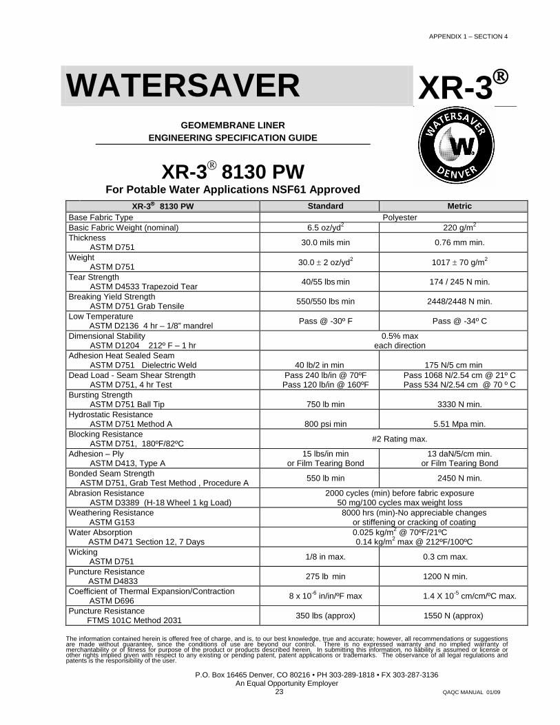
WATERSAVER XR-3
GEOMEMBRANE LINER ENGINEERING SPECIFICATION GUIDE
XR-3 8130 PW For Potable Water Applications NSF61 Approved
XR-3 8130 PW Standard Metric Base Fabric Type Polyester Basic Fabric Weight (nominal) 6.5 oz/yd2 220 g/m2 Thickness
ASTM D751 30.0 mils min 0.76 mm min.
Weight ASTM D751 30.0 ± 2 oz/yd2 1017 ± 70 g/m2
Tear Strength ASTM D4533 Trapezoid Tear 40/55 lbs min 174 / 245 N min.
Breaking Yield Strength ASTM D751 Grab Tensile 550/550 lbs min 2448/2448 N min.
Low Temperature ASTM D2136 4 hr – 1/8” mandrel Pass @ -30º F Pass @ -34º C
Dimensional Stability ASTM D1204 212º F – 1 hr
0.5% max each direction
Adhesion Heat Sealed Seam ASTM D751 Dielectric Weld 40 lb/2 in min 175 N/5 cm min
Dead Load - Seam Shear Strength ASTM D751, 4 hr Test
Pass 240 lb/in @ 70ºF Pass 120 lb/in @ 160ºF
Pass 1068 N/2.54 cm @ 21º C Pass 534 N/2.54 cm @ 70 º C
Bursting Strength ASTM D751 Ball Tip 750 lb min 3330 N min.
Hydrostatic Resistance ASTM D751 Method A 800 psi min 5.51 Mpa min.
Blocking Resistance ASTM D751, 180ºF/82ºC #2 Rating max.
Adhesion – Ply ASTM D413, Type A
15 lbs/in min or Film Tearing Bond
13 daN/5/cm min. or Film Tearing Bond
Bonded Seam Strength ASTM D751, Grab Test Method , Procedure A 550 lb min 2450 N min.
Abrasion Resistance ASTM D3389 (H-18 Wheel 1 kg Load)
2000 cycles (min) before fabric exposure 50 mg/100 cycles max weight loss
Weathering Resistance ASTM G153
8000 hrs (min)-No appreciable changes or stiffening or cracking of coating
Water Absorption ASTM D471 Section 12, 7 Days
0.025 kg/m2 @ 70ºF/21ºC 0.14 kg/m2 max @ 212ºF/100ºC
Wicking ASTM D751 1/8 in max. 0.3 cm max.
Puncture Resistance ASTM D4833 275 lb min 1200 N min.
Coefficient of Thermal Expansion/Contraction ASTM D696 8 x 10⁻⁶ in/in/ºF max 1.4 X 10⁻⁵ cm/cm/ºC max.
Puncture Resistance FTMS 101C Method 2031 350 lbs (approx) 1550 N (approx)
The information contained herein is offered free of charge, and is, to our best knowledge, true and accurate; however, all recommendations or suggestions are made without guarantee, since the conditions of use are beyond our control. There is no expressed warranty and no implied warranty of merchantability or of fitness for purpose of the product or products described herein. In submitting this information, no liability is assumed or license or other rights implied given with respect to any existing or pending patent, patent applications or trademarks. The observance of all legal regulations and patents is the responsibility of the user.

P.O. Box 16465 Denver, CO 80216 • PH 303-289-1818 • FX 303-287-3136 An Equal Opportunity Employer
24 QAQC MANUAL 01/09
WATERSAVER HYPALON
GEOMEMBRANE LINER
ENGINEERING SPECIFICATION GUIDE
36 mil HYPALON Black, Reinforced - Polyester
10x 10x 1,000d
PROPERTY TEST METHOD SPECIFIED VALUES
MINIMUM SPEC TYPICAL VALUES
Thickness 1) Overall (Mils) ASTM D-751 34 36 2) Min over Scrim Optical method 11 pass Test Properties (each direction) ASTM D-751 Grab Method Breaking Strength (lbs) Machine Direction 225 280 Cross Direction Elongation at Break (%) 50 90 Tear Popagation (lbs) ASTM D-751 Tongue Tear 70 90 (8x8 sample) Hydrostatic Resistance (psi) ASTM D-751 Method A 300 425 Procedure 1 Puncture resistance, (lbs) FTMS 101C, Method 2031 200 240 Bonded Seam Strength (lbs) ASTM D751 Modified (12 in./min.) 200 90% of parent material Ply Adhesion (lbs/in width) ASTM D413 Machine Method, 8 lbs 10 Type A, (12 in./mm)
Ozone resistance ASTM D-1149, 1/8” Bent loop, 100 pphm @ 104° F., 7 days No effect Pass
Low Temperature ASTM D2136, 1/8” Mandrel 4 hrs. @ -40 deg F. Pass Pass
The information contained herein is offered free of charge, and is, to our best knowledge, true and accurate; however, all recommendations or suggestions are made without guarantee, since the conditions of use are beyond our control. There is no expressed warranty and no implied warranty of merchantability or of fitness for purpose of the product or products described herein. In submitting this information, no liability is assumed or license or other rights implied given with respect to any existing or pending patent, patent applications or trademarks. The observance of all legal regulations and patents is the responsibility of the user.

P.O. Box 16465 Denver, CO 80216 • PH 303-289-1818 • FX 303-287-3136 An Equal Opportunity Employer
25 QAQC MANUAL 01/09
WATERSAVER HYPALON
GEOMEMBRANE LINER
ENGINEERING SPECIFICATION GUIDE
45 mil HYPALON Black, Reinforced - Polyester 1,000d
Membrane is .045in nominal thickness, scrim-reinforced,
uncured (thermoset) black Hypalon
PROPERTY TEST METHOD SPECIFIED VALUES
MINIMUM SPEC TYPICAL VALUES
Thickness 1) Overall (Mils) ASTM D-751 34 36 2) Min over Scrim Optical method 11 pass Test Properties (each direction) ASTM D-751 Grab Method Breaking Strength (lbs) Machine Direction 225 280 Cross Direction Elongation at Break (%) 50 90 Tear Popagation (lbs) ASTM D-751 Tongue Tear 70 90 (8x8 sample) Hydrostatic Resistance (psi) ASTM D-751 Method A 300 425 Procedure 1 Puncture resistance, (lbs) FTMS 101C, Method 2031 200 240 Bonded Seam Strength (lbs) ASTM D751 Modified (12 in./min.) 200 90% of parent material Ply Adhesion (lbs/in width) ASTM D413 Machine Method, 8 lbs 10 Type A, (12 in./mm)
Ozone resistance ASTM D-1149, 1/8” Bent loop, 100 pphm @ 104° F., 7 days No effect Pass
Low Temperature ASTM D2136, 1/8” Mandrel 4 hrs. @ -40 deg F. Pass Pass
The information contained herein is offered free of charge, and is, to our best knowledge, true and accurate; however, all recommendations or suggestions are made without guarantee, since the conditions of use are beyond our control. There is no expressed warranty and no implied warranty of merchantability or of fitness for purpose of the product or products described herein. In submitting this information, no liability is assumed or license or other rights implied given with respect to any existing or pending patent, patent applications or trademarks. The observance of all legal regulations and patents is the responsibility of the user.

P.O. Box 16465 Denver, CO 80216 • PH 303-289-1818 • FX 303-287-3136 An Equal Opportunity Employer
26 QAQC MANUAL 01/09
APPENDIX II NDT METHODS FOR FIELD SEAMS
A. Air Lance Testing This method is applicable for all field seams, including seams around pipe penetrations, repairs and accessories. A description of the air lance test follows.
All field seams shall be non-destructively tested over their full length. An air lance apparatus shall be used for this testing as described in this Appendix. The air lance shall be capable of supplying 30 psi through a 3/16 inch diameter nozzle. The air stream shall be directed at the edge of the seam no more than two inches from the seam edge. Enough time shall be allowed for the seams to develop adequate strength before commencement of testing. Any defects found during testing shall be marked, repaired, and retested with the air lance. All repairs shall be performed as described in Section 6.3.2 (Remedial Action).
B. Vacuum Box Testing for Hot Air Field Welds
For areas where air lance or pressurized seam testing is inappropriate, vacuum box testing may be used.
This method consists of creating a pressure differential across a seam and observing for bubbles in a film of liquid medium over the low pressure side, within the vacuum chamber. The vacuum chamber has a viewing port that allows observation of the seam area being tested. The sensitivity of the method is dependent on the pressure differential and the liquid used for testing. As long as the pressure differential can be maintained across the area tested, this method can be used. (ASTM E515, 5/90)
The following equipment comprises the vacuum box apparatus:
Vacuum Pump. The vacuum pump shall be fuel or electric powered and capable of sustaining the required vacuum for the duration of the test. Vacuum Gauge. The vacuum gauge shall be capable of registering, as a minimum to 70kPa (10 psi) in increments of 5 kPa (3/4 psi). Calibration and adjustment. The calibration of the vacuum gauge shall be checked and adjusted periodically, and routinely at a minimum of once every 12 months. Foaming Solution. The foaming solution shall be pre-mixed with water at a ratio conducive to the formation of bubbles. It shall be dispensed by spray, brush, or any other convenient means. The foaming solution should not be detrimental to the geomembrane. NOTE: If the component to be tested has parts made of polyethylene or structural plastics, the test fluid must not promote environmental stress cracking (E.S.C.) (ASTM E515, 5/90) Vacuum Chamber. The vacuum chamber shall have an open bottom and a clear viewing panel on top. It shall be an appropriate and convenient size and shape, made of rigid materials and equipped with a vacuum gauge, valve, and soft, pliable gasket around the periphery of the open bottom.
Testing of the field seam proceeds as follows:
The area of the seam to be evaluated should be clean and free of soil or foreign objects which might prohibit a good seal from being formed between the vacuum chamber and the geomembrane. Energize the vacuum pump.

P.O. Box 16465 Denver, CO 80216 • PH 303-289-1818 • FX 303-287-3136 An Equal Opportunity Employer
27 QAQC MANUAL 01/09
Wet an area immediately adjacent to and including the geomembrane seam measuring approximately twice the width and length of the vacuum chamber with a foaming solution.
Place and center the long axis of the vacuum chamber over the long axis of the seam or defect with the gasket in contact with the geomembrane surface over the wet area of geomembrane seam or test area.
For evaluation of geomembrane defects, center the vacuum chamber over the defect.
Apply a normal force to the top of the vacuum chamber to affect a seal and open the vacuum valve.
Ensure that a leak tight seal is created between the vacuum chamber gasket and the geomembrane material. For most cases, minimum vacuum of 28 to 55 kPa (4 to 8 psi) should be registered on the vacuum gauge is appropriate.
With the vacuum applied, maintain the normal force and observe the geomembrane seam through the viewing port for bubbles resulting from the flow of air through defects in the seam. The vacuum should be held over the test site for a duration of not less than 10 seconds. If the vacuum cannot be held for the minimum 10 seconds, the test area shall be marked as untested. If bubbles appear on the geomembrane seam, turn the three-way vacuum valve to vent the chamber and remove the vacuum chamber from the seam. The defective area should then be marked for later repair. If bubbles do not appear through the geomembrane seam within the specified dwell time, turn the vacuum valve to vent the chamber and remove the vacuum chamber from the seam. Move the vacuum chamber to the adjoining portion of the seam length overlapping the previously tested area by a distance no less than 10 percent of the minimum chamber length or at least 50mm (2 inches), whichever is the greater and repeat the procedure until the entire seam has been tested.
Any defects found during testing shall be marked, repaired, and retested with the vacuum box. All repairs shall be performed as described in Section 6.3.2 (Remedial Action).
P.O. Box 16465 Denver, CO 80216 • PH 303-289-1818 • FX 303-287-3136 An Equal Opportunity Employer
28 QAQC MANUAL 01/09
APPENDIX III FIELD SEAM DETAIL

P.O. Box 16465 Denver, CO 80216 • PH 303-289-1818 • FX 303-287-3136 An Equal Opportunity Employer
29 QAQC MANUAL 01/09
APPENDIX IV SEAM REQUIREMENTS
PRIMARY FACTORY SEAM METHODS
PVC - Chemical <1% Solids
rPP - Thermal
RLLDPE - Thermal
CSPE - Thermal
XR PRODUCTS - Thermal
SECONDARY FACTORY SEAM METHODS
PVC - Thermal
PRIMARY FIELD SEAMING METHODS
PVC - Chemical <1% Solids or Thermal
rPP - Thermal
RLLDPE - Thermal
CSPE - Thermal
XR PRODUCTS - Thermal
PRIMARY DETAIL & REPAIR METHODS
PVC - Chemical <1% Solids or Thermal
Rpp - Thermal
RLLDPE - Thermal
CSPE - Thermal
XR PRODUCTS - Thermal

P.O. Box 16465 Denver, CO 80216 • PH 303-289-1818 • FX 303-287-3136 An Equal Opportunity Employer
30 QAQC MANUAL 01/09
APPENDIX V RAW MATERIAL QUALIFICATIONS
2.1 RAW MATERIAL QUALIFICATION
2.1.1 PVC
Only first quality phthalate and/or phosphate plasticizers shall be used. The compound must also contain a biocide at a viable formation level. The use of water soluble ingredients is prohibited.
2.1.2 CSPE
Hypalon pond liners are made from a special polymer that is compounded,
fabricated and installed in a thermoplastic state. Factory seam fabrication, under controlled conditions, is done by a precise combination of heat and pressure.

P.O. Box 16465 Denver, CO 80216 • PH 303-289-1818 • FX 303-287-3136 An Equal Opportunity Employer
31 QAQC MANUAL 01/09
APPENDIX VI PGI 1104 Appendix B Testing Clarifications and Details This appendix lists the clarifications and details of the testing methods used in the PGI specification. In some cases multiple test procedures exist within test methods and testing choices are required. This appendix makes note of the test criteria that was used to compile these specifications. General When both US and metric values are shown the value for acceptance is the US value. Metric values are conversions and may contain rounding errors. Test Method Clarification and Details ASTM D751 Test Methods for Coated Fabrics
o o For Hydrostatic Burst use Section 33, Procedure A, “Pressure Application by Mullen Type Hydrostatic Tester”
o o Units of pressure in pounds per square inch (psi) or kiloPascals (kPa) ASTM D882 Tensile Properties of Thin Plastic Sheeting
o o Use Method A o o D882 method may be used for PVC film up to 60 mil (1.5mm) thick o o Units are in pounds of force per inch of width (lbs/in) o o Metric units are in kiloNewtons per meter of width (kN/m), or Newtons per millimeter of width
(N/mm) which are equivalent units o o Factory Seam Shear Testing
- - Use ASTM D882 Method A - - ASTM D882 may be used for thicknesses greater than 1.0 mm (40 mil)
for seam testing - - Use 25.4 mm wide (1”) specimens - - Use grip separation of 51 mm (2 in) plus the seam width - - Crosshead speed of 510 mm/min (20 in/min)
o o Factory Seam Peel Testing - - Use ASTM D882 Method A - - Use 25.4 mm wide (1”) specimens - - Position grips 13 mm (1/2”) on either side of seam - - Crosshead speed of 51 mm/min (2 in/min)
ASTM D1004 Initial Tear Resistance of Plastic Film and Sheeting
o o Units are in pounds of force to initiate tear in the specially die-cut specimen (lbs) or in Newtons of force (N)
ASTM D1203 Volatile Loss from Plastics Using Activated Carbon Methods
o o Use method A ASTM D1204 Linear Dimensional Changes of Thermoplastic Film at Elevated Temp.
o o Test specimens at 100C for 15 minutes o o Measure percent change in lineal dimensions
ASTM D1239 Resistance of Plastic Films to Extraction by Chemicals
- - ASTM D1239 may be used for thicknesses greater than 1.0 mm (40 mil) o o Test specimens in 50° C (122° F) water for twenty-four hours o o Measure percent change in weight
ASTM D1790 Brittleness Temperature of Plastic Sheeting by Impact
o o 50% of specimens must pass at specified temperature ASTM D 2124 For plasticizer extraction, followed by GC or GCMS for identification and molecular weight
determination.

P.O. Box 16465 Denver, CO 80216 • PH 303-289-1818 • FX 303-287-3136 An Equal Opportunity Employer
32 QAQC MANUAL 01/09
ASTM D5199 Measuring the Nominal Thickness of Geosynthetics
o o US units of thousandths of an inch (0.001 inches = 1 mil) o o Metric unit of millimeters of thickness (mm)
ASTM G160 Evaluating Microbial Susceptibility of Nonmetallic Materials by Soil Burial
o o Bury sample in prepared soil for 30 days o o Perform test on actual liner sheet samples o o Measure maximum change in properties as shown in specification

P.O. Box 16465 Denver, CO 80216 • PH 303-289-1818 • FX 303-287-3136 An Equal Opportunity Employer
33 QAQC MANUAL 01/09
APPENDIX VII Enhanced Testing Information For Reinforced Geomembranes. ASTM D751 Test Methods for Coated Fabrics Dimensions and Mass - (Thickness & Weight) Breaking Strength Procedure A - (Grab) 4” wide specimen / 1” Grip Procedure B - (Strip) 1” wide specimen / 1” Grip Elongation - % at fabric break Bursting Strength - Tension Testing Machine with Ring Clamp (1.000” Dia. Steel Ball) Hydrostatic Resistance Procedure/Method A – Mullen Type Tester Adhesion Coating (to fabrics) - Two 1” wide Specimens welded together leaving two free ends for peel. “It can be difficult to separate the polymer directly from the scrim” Seam Strength - NSF Modified – 4” Wide Specimen - Most field tensiometers are only wide enough for 1” Wide Specimens. Dead Load Seam Test - TD & MD ASTM D3776 - Mass Per Unit Area ASTM D2136 – Low Temp - 5X Magnifier, 1” x 4” samples. ASTM D5884 – Tear - D-35 Committee (index test) Typically, the higher value indicates ganging of fibers, Lower values indicate fibers breaking one at a time. Standard strain rate (12 +/- 0.5”/min) ASTM D4833 – Puncture – D-35 Committee (index test) Rod Diameter 0.35”/flat end chamfered 45 deg. May be inappropriate for some large interstices. UV Resistance (Weathering Wet/Dry Cycle) ASTM G26 withdrawn, replaced by G155 Weathering Resistance (Carbon-Arc) –ASTM G23 withdrawn, replaced by G152 &G153 See ASTM – D151 for detailed information covering difference between Carbon & Xenon – Arc. Ply Adhesion (Modified Machine Method) Under ASTM D 413 Similar To ASTM D 751 ADHESIVE COATING. FTMS 101C cancelled. Incorporated into Mil-Std-3010, Puncture Resistance – Method 2065 Puncture Probe 1/8” Spherical Radius W \ 2” Long Taper. http://assist.daps.dla.mil ASTM 1204 – Linear Dimensional Changes % (MFG Specified Test Temperatures)
UV Resistance (General *)
Shorter wavelengths of radiation contain more energy. Narrow Band wavelengths used for testing in the US. Broad Band wave lengths used for testing in Europe.
* Sun Spots, Atlas Testing.