Manuale Uso EN - Krypto Security Smart...Total zones 10 30 100 200 Relay outputs on control-panel...
60
CEI 79-2 EN 50131-3 EN 50131-6 CEB T014 SmartLiving Anti-intrusion control panels and security systems User’s manual
Transcript of Manuale Uso EN - Krypto Security Smart...Total zones 10 30 100 200 Relay outputs on control-panel...

User’s manual
1
CEI 79-2EN 50131-3EN 50131-6CEB T014
SmartLivingAnti-intrusion control panels and security systemsUser’s manual

2
Anti-intrusion control panels
WarrantyINIM Electronics s.r.l. (Seller, Our, Us) warrants the original purchaser that thisproduct shall be free from defects in materials and workmanship under normaluse for a period of 24 months. As INIM Electronics s.r.l. does not install thisproduct directly, and due to the possibility that it may be used with otherequipment not approved by Us; INIM Electronics s.r.l. does not warrant againstloss of quality, degradation of performance of this product or actual damage thatresults from the use of products, parts or other replaceable items (such asconsumables) that are neither made nor recommended by INIM Electronics.Seller obligation and liability under this warranty is expressly limited to repairingor replacing, at Seller's option, any product not meeting the specifications. In noevent shall INIM Electronics s.r.l. be liable to the purchaser or any other personfor any loss or damage whether direct ot indirect or consequential or incidental,including without limitation, any damages for lost profits, stolen goods, or claimsby any other party caused by defective products or otherwise arising from theincorrect or otherwise improper installation or use of this product.This warranty applies only to defects in parts and workmanship relating to normaluse. It does not cover:• damage arising from improper maintenance or negligence• damage caused by fire, flood, wind or lightning• vandalism• fair wear and tearINIM Electronics s.r.l. shall, at its option, repair or replace any defective products.Improper use, that is, use for purposes other than those mentioned in thismanual will void the warranty. Contact Our authorized dealer, or visit our websitefor further information regarding this warranty.
Limited warranty
INIM Electronics s.r.l. shall not be liable to the purchaser or any other person fordamage arising from improper storage, handling or use of this product.Installation of this Product must be carried out by qualified persons appointed byINIM Electronics. Installation of this Product must be carried out in accordancewith Our instructions in the product manual.
CopyrightThe information contained in this document is the sole property of INIMElectronics s.r.l. No part may be copied without written authorization from INIMElectronics s.r.l.All rights reserved.
European Directive compliance
Hereby INIM Electronics s.r.l. declares that the SmartLiving series of intrusion-control panels, the Air2 series of devices and the SmartLink product are incompliance with the essential requirements and other relevant provisions ofDirective 1999/5/CE.Moreover, INIM Electronics s.r.l. also declares that all other devices mentioned inthis manual are in compliance with the essential requirements and other relevantprovisions of Directive 2004/108/CE.The full declarations of conformity can be found at URL: www.inim.biz/dc.html.
State-of-the-art installations (DM 37/08)
The devices described in this manual, in accordance with the settings selectedduring the installation phase and the following illustrated guidelines are,alternatively, in compliance with the the Italian Normative CEI 79-2:1998+Ab:2000 performance level 2 or European Normative CEI EN 50131-3:2009 (in reference to Control and indicating equipment - intrusion controlpanels) and CEI EN 50131-6:2008 (in reference to Power supplies) security grade2.In support of research, development, installation, testing, commissioning andmaintenance of intrusion alarm systems installed in buildings please refer to thefollowing normative documents:CEI 79-3 e CEI CLC/TS 50131-7.When installing INIM systems, it is up to the installer company to install systemsequipped with Normative CEI 79-2 compliant devices rather than devicescompliant with European Normatives series EN50131 within and not over theDOWs summarized in amendment CEI 79-2;V1:2010.

User’s manual
3
Table of contents
Warranty . . . . . . . . . . . . . . . . . . . . . . . . . . . . . . . . . . . . . . . 2Limited warranty . . . . . . . . . . . . . . . . . . . . . . . . . . . . . . . . . 2Copyright . . . . . . . . . . . . . . . . . . . . . . . . . . . . . . . . . . . . . . 2European Directive compliance. . . . . . . . . . . . . . . . . . . . . . . . 2State-of-the-art installations (DM 37/08) . . . . . . . . . . . . . . . . 2Table of contents . . . . . . . . . . . . . . . . . . . . . . . . . . . . . . . . . 3
Chapter 1 General information . . . . . . . . . . . . . . . . . . . . . . . . . . . . . 51-1 Manufacturer's details . . . . . . . . . . . . . . . . . . . . . . . . . . . . . . . . . . 51-2 Description of the product and various models . . . . . . . . . . . . . . . . . 51-3 Environmental Conditions . . . . . . . . . . . . . . . . . . . . . . . . . . . . . . . . 61-4 Products certified and conforming to directives . . . . . . . . . . . . . . . . . 61-5 Manuals . . . . . . . . . . . . . . . . . . . . . . . . . . . . . . . . . . . . . . . . . . . . 71-6 Operator Qualifications . . . . . . . . . . . . . . . . . . . . . . . . . . . . . . . . . . 71-7 Access Levels . . . . . . . . . . . . . . . . . . . . . . . . . . . . . . . . . . . . . . . . 81-8 Conventions – Glossary . . . . . . . . . . . . . . . . . . . . . . . . . . . . . . . . . 8
Chapter 2 The SmartLiving System. . . . . . . . . . . . . . . . . . . . . . . . . . 92-1 Introduction . . . . . . . . . . . . . . . . . . . . . . . . . . . . . . . . . . . . . . . . . 92-2 The Technologies . . . . . . . . . . . . . . . . . . . . . . . . . . . . . . . . . . . . . . 102-3 Keypads . . . . . . . . . . . . . . . . . . . . . . . . . . . . . . . . . . . . . . . . . . . . 102-4 Reader - nBy. . . . . . . . . . . . . . . . . . . . . . . . . . . . . . . . . . . . . . . . . 172-5 User Codes . . . . . . . . . . . . . . . . . . . . . . . . . . . . . . . . . . . . . . . . . . 192-6 Keys . . . . . . . . . . . . . . . . . . . . . . . . . . . . . . . . . . . . . . . . . . . . . . 202-7 Multi-system access . . . . . . . . . . . . . . . . . . . . . . . . . . . . . . . . . . . . 212-8 Telephone functions . . . . . . . . . . . . . . . . . . . . . . . . . . . . . . . . . . . . 212-9 WEB / e-mail functions . . . . . . . . . . . . . . . . . . . . . . . . . . . . . . . . . . 22
2-10 AlienMobile Application . . . . . . . . . . . . . . . . . . . . . . . . . . . . . . . . . . 222-11 Arming scenarios . . . . . . . . . . . . . . . . . . . . . . . . . . . . . . . . . . . . . . 22
Chapter 3 Shortcuts . . . . . . . . . . . . . . . . . . . . . . . . . . . . . . . . . . . . 243-1 Keypad shortcuts. . . . . . . . . . . . . . . . . . . . . . . . . . . . . . . . . . . . . . 243-2 Shortcut with code. . . . . . . . . . . . . . . . . . . . . . . . . . . . . . . . . . . . . 253-3 Key and Reader shortcuts . . . . . . . . . . . . . . . . . . . . . . . . . . . . . . . . 253-4 Shortcut list . . . . . . . . . . . . . . . . . . . . . . . . . . . . . . . . . . . . . . . . . 26
Chapter 4 Voice functions . . . . . . . . . . . . . . . . . . . . . . . . . . . . . . . . 27
Chapter 5 Using the system. . . . . . . . . . . . . . . . . . . . . . . . . . . . . . . 285-1 Managing alarms . . . . . . . . . . . . . . . . . . . . . . . . . . . . . . . . . . . . . . 285-2 Arming and disarming partitions . . . . . . . . . . . . . . . . . . . . . . . . . . . 295-3 Voice box and intercom functions . . . . . . . . . . . . . . . . . . . . . . . . . . 315-4 Activations . . . . . . . . . . . . . . . . . . . . . . . . . . . . . . . . . . . . . . . . . . 325-5 View. . . . . . . . . . . . . . . . . . . . . . . . . . . . . . . . . . . . . . . . . . . . . . . 345-6 Activating/Deactivating outputs. . . . . . . . . . . . . . . . . . . . . . . . . . . . 375-7 Change date and time . . . . . . . . . . . . . . . . . . . . . . . . . . . . . . . . . . 385-8 Keypad settings. . . . . . . . . . . . . . . . . . . . . . . . . . . . . . . . . . . . . . . 385-9 Change PIN. . . . . . . . . . . . . . . . . . . . . . . . . . . . . . . . . . . . . . . . . . 40
5-10 Change telephone numbers. . . . . . . . . . . . . . . . . . . . . . . . . . . . . . . 40

4
Anti-intrusion control panels
5-11 Teleservice request . . . . . . . . . . . . . . . . . . . . . . . . . . . . . . . . . . . . 415-12 Overtime request . . . . . . . . . . . . . . . . . . . . . . . . . . . . . . . . . . . . . 415-13 Thermostat . . . . . . . . . . . . . . . . . . . . . . . . . . . . . . . . . . . . . . . . . . 425-14 Teleservice via Nexus. . . . . . . . . . . . . . . . . . . . . . . . . . . . . . . . . . . 435-15 Codes . . . . . . . . . . . . . . . . . . . . . . . . . . . . . . . . . . . . . . . . . . . . . 435-16 Listen-in. . . . . . . . . . . . . . . . . . . . . . . . . . . . . . . . . . . . . . . . . . . . 455-17 Partition status enquiry . . . . . . . . . . . . . . . . . . . . . . . . . . . . . . . . . 455-18 Commands over-the-phone . . . . . . . . . . . . . . . . . . . . . . . . . . . . . . 465-19 Alien function keys . . . . . . . . . . . . . . . . . . . . . . . . . . . . . . . . . . . . 475-20 Using the SmartLAN/G . . . . . . . . . . . . . . . . . . . . . . . . . . . . . . . . . . 495-21 Using AlienMobile application . . . . . . . . . . . . . . . . . . . . . . . . . . . . . 505-22 Photo frame . . . . . . . . . . . . . . . . . . . . . . . . . . . . . . . . . . . . . . . . . 51
Appendix A Technical terminology and Glossary. . . . . . . . . . . . . . . . . . 52
Appendix B Shortcuts at default . . . . . . . . . . . . . . . . . . . . . . . . . . . . . 56
Appendix C Fault signals . . . . . . . . . . . . . . . . . . . . . . . . . . . . . . . . . . 57Notes . . . . . . . . . . . . . . . . . . . . . . . . . . . . . . . . . . . . . . . . . 59

User’s manual
General information 5
Chapter 1
GENERALINFORMATION
1-1Manufacturer's detailsManufacturer: INIM Electronics s.r.l.Production plant: Via Fosso Antico - Centobuchi
63076 Monteprandone (AP) - ItalyTel: +39 0735 705007Fax: +39 0735 704912e-mail: [email protected]: www.inim.bizThe persons authorized by the manufacturer to repair or replace the parts of thissystem, hold authorization to work on INIM Electronics brand devices only.
1-2Description of the productand various models
Description: Intrusion control panelModels: SmartLiving 505
SmartLiving 515SmartLiving 1050SmartLiving 1050LSmartLiving 10100L
Applied Normative: CEI 79-2:1998+Ab:2000, CEI EN 50131-3:2009 and CEI EN50131-6:2008
Certification agency: IMQ - Security systemsSecurity rating: 2The following table describes the main features of the various models of the controlpanels:
Table 1: Control panel - Main FeaturesSmartLiving intrusion control panels 505 515 1050 1050L 10100L
Total terminals 5 15 50 100Terminals on panel 5 10
Terminals on panel configurable as inputs 5 10Terminals on panel configurable as Rollerblind/Shock 2
Terminals on panel configurable as outputs 0 5Total zones 10 30 100 200
Relay outputs on control-panel motherboard 1Open-collector outputs on panel motherboard 2 (150mA) 2 (500mA)
Partitions 5 10 15Keypads (Joy, nCode/G, Concept/G, Alien) 5 10 15
nBy Readers 10 20 30Digital keys and keyfobs 50 100 150
Possible key combinations 4294967296Codes 30 50 100
Scenarios 30Timer 10 20
Recordable Events 500 1000

6 General information
Anti-intrusion control panels
1-3Environmental ConditionsThe Joy/GR, Joy/MAX, nCode/G, Concept/G, Alien/S, Alien/G, IB100, FLEX5, Nexus andnBy/X peripheral devices are for indoor installation only and operate best under thefollowing environmental conditions:• Temperature: from -10° to +40°C• Maximum humidity: 75% (without condensation)• Environmental class: IIThe nBy/S reader is suitable for outdoor installation and operates best under thefollowing conditions:• Temperature: from -25° to +70°C• Maximum humidity: 93% (without condensation)• Protection grade: IP34• Environmental class: IV
1-4Products certified andconforming to directives
When duly programmed, the SmartLiving intrusion control panel and the devicesdescribed in this manual have been certified by the IMQ - Security Systems agency ascompliant with CEI 79-2:1998+Ab:2000, CEI EN 50131-3:2009 and CEI EN 50131-6:2008.The Control panel enclosure houses the following certified devices:• INIM Electronics switching-power supply• Motherboard (IN082 or IN088)• SmartLogos30M voice board (accessory item)• FLEX5/U input/output expansion board (accessory item)• AUXREL32 relay board (accessory item)• SmartLAN/SI and SmartLAN/G LAN interface boards (accessory items)• IB100/RU BUS isolator board (accessory item)• ProbeTH thermal-probe kit for battery-charge optimization (accessory item)• TamperNO tamper-protection kit (accessory item)• Backup battery, 12 V @ 17 Ah• Motherboard (IN082 and IN088) integrated Type B notification apparatusThe control panel compliancy is also guaranteed when connected to the followingcertified devices:• FLEX5/P input/output expansion boards• Joy/MAX, Joy/GR, Concept/G, nCode/G keypads• nBy/S outdoor-mount proximity readers• nBy/X universal-mount proximity readers• IB100/RP BUS isolator• Self-powered IB100/A BUS isolator• nCard access-control card for proximity readers• Tag for nKey or nBoss proximity readers• Self-powered sounderflashers for outdoor installation: Ivy, Ivy-F, Ivy-M, Ivy-FM, Ivy-
B, Ivy-BF, Ivy-BM, Ivy-BFM• Wireless system devices: AIR2, AIR2-BS100 (transceiver), Air2-IR100 (PIR
detector), Air2-MC100 (magnetic contact)
TYPE B NOTIFICATION APPARATUS
ATS2 notification apparatus (refer to EN50131-1:2008-02, paragraph 8.6 Notification,Table 10, page 46, Grade 2 and EN50136) characterized by:• Transmission time - classification D2 (60 seconds)• Transmission time - max. values M2 (120 seconds)• Classification time - classification T2 (25 hours)• S0 Substitution security (no detection of device substitution)• I0 Information security (no detection of message substitution)

User’s manual
General information 7
1-5Manuals
1-5-1Installer's manualThis manual (not included in the package) can be purchased from your retailer. You (theinstaller) should read carefully through it in order to become familiar with all thecomponents and operating procedures of the SmartLiving system.In order to provide adequate protection, the installer must adhere to all themanufacturer's guidelines relating to the active and passive security devices of thissystem.
1-5-2Installation andprogramming guide
This guide is included in the control panel package and provides all the instructions andillustrations necessary for fast installation and programming of the SmartLiving system.It provides step by step descriptions of the procedures required for the system wiring,the various connections and first powerup. It also provides a table for the peripheraladdressing process and a quick guide indicating default parameters and values and howto programme/change them directly from the keypad.
1-5-3User's Manual(this manual)
MANUAL CODEDCMUINE0SLIVINGE
REVISION5.10The installer should read carefully through the user's manual (supplied with eachcontrol panel). Once the system has been installed, you must ensure that the User'sManual is available to the users for consultation, and that they fully understand how thesystem works and are aware of all the functions, settings and procedures.It is the installer's responsibility to inform the system users that, regardless of itscapabilities, an intrusion alarm system is not a substitute for the necessary precautionsbuilding occupants must take to prevent intrusion.
1-6Operator Qualifications
1-6-1InstallerThe installer is the person (or group of persons) who sets up and programs the entiresecurity system in accordance with the purchaser's requirements and in respect of thesafety laws in force. As the only individual in contact with system users, it is theinstaller's responsibility to instruct them on how to use the security system properly.Under normal circumstances, the installer is not allowed to arm/disarm the systemwithout previous authorization from the user. All the system partitions must bedisarmed before accessing the parameter programming phase.The access code of the installer is a level 3 access code.
1-6-2UserThe users are the occupants of the building where this intrusion control panel isinstalled. Only authorized users can access and operate the system.Thanks to the extreme flexibility of the system, the most common operations can becarried out without authorization. This operating method must be expressly requestedby the main user, as it considerably lowers the security level of the system and maycause false alarms, accidental arm/disarm operations, etc.A system access code can be associated with each user. The programming processallows you to define the code hierarchy:• User • Manager • Master
The system codes can carry out, in accordance with their assigned level in thesystem hierarchy (the "User" being the lowest level), the following operations on allother codes that are inferior hierarchically:

8 General information
Anti-intrusion control panels
•• enable/disable•• change PIN•• change the programming parameters
If the system programming complies with security grade 3 of EN 50131, some partitionarming or delete memory operations, requested from a keypad, may be authorized bythe entry of a level 3 code (installer code) as well as by a user code.
1-7Access LevelsThe normative defines the following system-access levels, regardless of system-accesslimitations:• Level 1 - access by any person (e.g. passer-by)• Level 2 - user access• Level 3 - installer or maintenance operator access (authorized by user - level 2)• Level 4 - manufacturer access
1-8Conventions – GlossaryIn order to understand the terminology used in this manual and improve yourknowledge of this system and its operating procedures, read carefully through theGlossary (refer to Appendix A, Technical terminology and Glossary).The appendix contains the definitions of technical terms commonly used in the field ofsecurity, therefore, relevant to the SmartLiving system.

User’s manual
The SmartLiving System 9
Chapter 2
THE SMARTLIVINGSYSTEM
2-1IntroductionINIM Electronics wishes to thank you for choosing this SmartLiving intrusion controlsystem. Its advanced technology and user-friendly operations provide an extremelyhigh level of protection combined with ease-of use.INIM Electronics recommends that all parts of this manual be read thoroughly beforestarting up SmartLiving system. Once you have become accustomed to the day-to-dayoperations, your installer will explain and if required, program the advanced functionsprovided by the system.A typical system comprises:• SmartLiving control panel• intrusion detection devices (PIR or microwave detectors, magnetic contacts, linear
beam detectors, etc.)• system control peripherals: proximity readers, keypads• alarm signaling devices which generally signal the events detected by the system
(sounders, flashers, etc.)The keypad (Joy/GR, Joy/MAX, nCode/G, Concept/G, Alien/S or Alien/G) is anextremely flexible peripheral device which allows users to manage the system withease. The graphic display shows all the necessary information and provides anadvanced user-interface based on icons for instant and clear indications relating to theoperations to be performed. All users have PINs which allow them to access and controlthe system via the keypad in accordance with their permitted access level.Advanced voice technology guides you through the operations by means of clear voiceprompts which explain the operations you must undertake.nBy readers (2 versions available: nBy/S wall-mount and By/X flush-mount) allow youto access and control the system. Although these devices are not as flexible as keypads,they provide a quick and easy way of carrying out day-to-day operations such asarming and disarming the system. Authorized digital-key users can operate the systemin accordance with their programmed access level (enabled functions, etc.) by holdingthe key in front of the proximity key reader.All SmartLiving control panels are capable of managing INIM's “Air2” two-way wirelesssystem. This system integrates wireless devices (detectors, keyfobs, etc.) into thehardwired environment.SmartLiving control panels are capable of managing various event types (alarms, faults,tamper, code/key identification, arm/disarm operations, etc.) and event-responseactions (audible/visual signaling, telephone calls, SMS text messages over the GSMnetwork and, with the addition of the optional SmartLAN/G board, e-mails withattachments). The calls can be:
1. report calls to alarm receiving centres - via the most widely used reporting proto-cols.
2. voice calls to contact numbers - using advanced voice technology to inform con-tact persons of the active alarm condition.
Events can also be announced on JOY/MAX and Alien keypads.The SmartLiving intrusion control panel also provides automatic features, such as:• arm and disarm operations set up on a weekly basis• simple yet useful access-control functions which allow the system to deny access to
specific keys/codes at certain times• pre-set activation/deactivation of household devices (building automation) such as
courtesy lights• other similar automatic facilities.

10 The SmartLiving System
Anti-intrusion control panels
2-2The TechnologiesExpertise in the arena of total security and a commitment to precision and high qualityallow INIM's R & D professionals to deliver excellence in design technology anddependability through time.
2-2-1EASY4UThis user-friendly tool provides an interesting array of graphic features and functions.All SmartLiving intrusion control panels are controlled by keypads equipped with 96x32pixel graphic displays. The four-line alphanumeric display screen (16 characters perline) can be edited or used to view the icons associated with various customized user-operations. The keypad shortcuts allow time-consuming sequences to be transformedinto simple keystroke actions. They can be used for a variety of tasks and makeoperations less tedious and less error-prone. In this way, INIM has eliminated therepetitive sequences of keystrokes required by other systems available on the market.The use of customizable graphic-objects, which indicate the system status, helps usersto understand what is happening on the system.Besides accepting various commands (Away Arm, Stay Arm, Disarm, etc.), the nByreader also allows users to manage the "shortcuts" programmed on the keypad.The Joy/MAX and Alien keypads both have built-in nBy proximity readers.
2-2-2VOIBThis is an acronym for Voice Over Inim-Bus. VOIB technology allows the system tomanage end-to-end digitized voice transmissions at extremely high-speed over theIBUS. Voice transmissions can be carried to all points of the IBUS. The JOY/MAX andAlien keypads have built-in microphones and speakers for message recording andplayback. The 30 minute capacity voice board allows each event to be associated with amessage. Voice digitizing and compression allow the signal to be transmitted in datapackets over the bus to recipient keypads where it is announced. Voice digitizing andthe characteristics of the I-BUS allow end-to-end “noise-immune” voice transmissionswithout the need of any additional wiring.
2-3KeypadsThe keypad allow users to manage all aspects of the security system. SmartLivingcontrol panels support JOY/GR, JOY/MAX, nCode/G, Concept/G, Alien/S and Alien/Gkeypads. The features of these keypads are described in the following table:
Table 2: Keypads - functionsModels Joy/MAX Joy/GR nCode/G Concept/G Alien/S Alien/G
Graphic display Monochromatic96x32
65536 colour touch screen4.3 inches480x272
7 inches800x480
Keys 23(in soft rubber)
23(touch) No
Signaling LEDs 4 NoBuzzer Yes
Terminals 2 1 No 2Microphone Yes No Yes
Speaker Yes No YesBuilt-in proximity reader Yes No Yes
Temperature sensor Yes No YesBacklight activated by proximity
sensor No Yes No
Keypad lock-out No Yes YesUSB port No YesSD card No Max. 32 GByte

User’s manual
The SmartLiving System 11
KEYSThe various keypad models have different functions, casings and key access. The keyson Joy keypads are protected a flip-cover which protects them from accidental pressingand dust; whereas, the keys of the nCode/G and Concept/G keypads are on view. TheConcept/G is a touch-screen keypad. Alien keypads are not equipped with keys butinstead have a colour touch screen that allows access to the system via touch or touch-screen pen (supplied with Alien/G).The installer assigns the partitions and portions/sections of the system that users, withassigned codes, will have access to via the keypad in use.
SHORTCUTSIt is possible to extend the use of some of the system shortcuts to users withoutassigned codes. In this way, SmartLiving control panels add further operating modes tothat of the traditional user menu which is only accessible after code entry.It is possible to use the shortcuts at the keypads (refer to “Shortcuts” in the Glossary)associated with keys . Generally, intrusion control panels do notallow access to the system via keypad without code entry. However, by means of theshortcuts associated with keys , ..., it is possible to enable building occupantsto access and operate on the system without code entry.The Alien touch screen user interface provides shortcuts such as the activation ofscenarios, and also applications such as device settings, which can be activated by thebuttons displayed on the screen without code entry.The installer must program the shortcuts to suit the system requirements and explainhow they are used. For example, it may be useful to allow all the building occupants toarm the system without code entry, as this operation increases the level of systemsecurity. However, operations which lower the level of system security should bereserved for code users only (thus allowing identification of users who disarm thesystem). Under normal circumstances, operations which increase system security canbe allowed without valid-code entry whereas, operations which lower system security(Disarm, Delete Alarm/Tamper memory, Deactivate Alarm/Tamper outputs) should beallowed only after valid-code entry.
CHRONOTHERMOSTATJOY/MAX and Alien keypads also provide a programmable chronothermostat function.This function allows you to set up zone management (one zone per keypad) of theheating/air-conditioning system.The temperature is gauged by a built-in temperature sensor. The hysteresis is fixed at0.4°C.
CONCEPT/G ACCESSThe Concept/G keypad provides a further two options relating to direct user access.A special feature allows activation of the backlight of the display and keys when usersapproach the keypad. This is achieved through a proximity sensor which can be
activated by pressing keys and simultaneously and deactivated by pressing and .
The other option, block/unblock keypad, can be achieved by pressing key for 3seconds. If the block keypad option is enabled, the display will show the icon opposite.
2-3-1The Joy, nCode andConcept keypad display
The brightness and contrast of the backlit-graphic LCD (96 x 32 pixel) can be adjustedby way of the respective options on the user menu (refer to paragraph 5-8 Keypadsettings).It is divided into four lines which continually provide information regarding the status ofthe system and control panel, without need of user-code entry.
1° line: 2° line: 3° line: 4° line:
The following table describes the messages which are shown on the keypad display, inaccordance with the actual status of the control panel:• Standby - shown when the control panel is functioning normally and there are no
alarm, tamper of fault events present on the system.• Zone alarm or tamper - shown when the control panel detects or signals violation on
a zone, both in the event of intrusion or detection of a lost device• Maintenance - shown when the control panel is in service mode for or maintenance
or programming purposes
18:23 01/02/2014DASIDASI--

12 The SmartLiving System
Anti-intrusion control panels
The icons which appear on the right side of the second line, provide informationregarding the system, therefore, their presence or status (fixed or flashing) depends onthe status they must signal:
Table 3: Display visualizationDis-play line
Control panel status
Standby Alarm or tamper Maintenance
1
The first line of the display shows the date and time.If at least one of the keypad partitions has saved an alarm or tamper event to the memory, the first line of the screen will flash the descriptions of the zones
concerned every 3 seconds.
NoteOpen zones are signaled by blinking onthe red LED .
If the control panel is in Service mode, a string will be shown indicating the address of the keypad in use (in the figure, the keypad is at address 3).
If you are using a JOY/MAX keypad, the date and room tem-perature will alternate on the screen every 3 seconds.
If you are using a Joy/MAX keypad, the string will also show the address of its built-in proximity reader (in the fig-
ure, the reader is at address 5).
If the “View open zones” control-panel option is enabled, the descriptions of zones that are not in standby status
when the keypad partitions disarm will be shown in sequen-tial order approximately every 3 seconds.
Any auto-bypassable zones will be shown in white on black background.
If the control panel is in Service mode and at least one of the keypad partitions has saved an alarm or tamper event to the memory, the above-described strings
will alternate on the display.
2left
The left side of the second line shows the characters that indicate the current status of the partitions the keypad is
assigned to:• D = partition disarmed• A = partition armed in Away mode (interior and
perimeter zones armed)• S = partition armed in Stay mode (perimeter
zones armed)• I = partition armed in Instant mode (perimeter
zones armed with no delay)• - = partition does not belong to the keypad
In the case of the SmartLiving 505 or 515, 5 characters indicating the status of partitions 1 to 5 will be shown.
In the case of the SmartLiving 1050 or 1050L, 10 characters indicating the status of partitions 1 to 10 will be shown.
• The display of the SmartLiving 10100L model,alternates at 3 second intervals, between 10 characters,indicating the status of partitions 1 to 10, and 5characters indicating the status of partitions 11 to 15.
In the event of a partition alarm or tam-per memory, the red LED on the
keypad and the characters correspond-ing to the partitions concerned will
blink.
The line is the same as when the con-trol panel is in standby condition.
If the “Show scenario” control panel parameter is active, the left side of the second line on the screen will display the current scenario.
2right The right side of the second line allows you to view several icons which provide visual information regarding the system.
For a detailed description of these icons refer to Table 4: Information icons.
3
4 Lines three and four on the display are occupied by the icons which correspond to the shortcuts assigned to the function keys , ..., .If no shortcuts are programmed on the keypad function keys, the respective spaces on the display will remain empty.
18:23 01/02/2014
Panel T03 K03 Service
18:23 PM 25.4 C
Mainten K03 P05
Panel T03
Panel T03
Panel T03
Mainten K03 P05
DASIDASI--
DASIDASI--
D SIDASI--
SCENARIO 001
DASIDASI--
Table 4: Information iconsKeypads Alien Name Not present On solid Blinking or interchanging icons
Telephone line Telephone line busy Telephone line down
Peripheral LossAll the peripherals in the system
configuration are responding properly (Present).
At least one peripheral (keypad, reader, expansion) is not
responding properly.
All the peripherals in the system configuration are responding prop-erly, however, loss of a peripheral
has been detected and cleared (Peripheral Loss memory).
Answerphone Answerphone function disabled Answerphone function enabled

User’s manual
The SmartLiving System 13
NoteIf duly programmed by the installer, the icon will be shown when Teleservice is enabled.
2-3-2 Using the keypadThe following section describes how the keys are normally used. Some of the keys mayhave specific functions which will be indicated when necessary.
Teleservice Teleservice disabled Teleservice enabled
Key False key
Peripheral tamperAll peripherals are properly
placed and all enclosures covers are closed.
At least one peripheral (keypad, reader, expansion) is in tamper status (enclosure open or device
dislodged).
All peripherals are properly placed and all enclosure covers are
closed, however, tamper was pre-viously detected and cleared
(Tamper memory).
Control panel Tam-per
The Control panel is properly placed and the enclosure is
closed.
The Control panel is in tamper status (enclosure open or device
dislodged).
The Control panel is properly placed and the enclosure is closed, however, panel tamper has been detected and cleared (Panel tam-
per memory).
Call on Nexus The Nexus/G communicator is engaged in a call
Sending SMS The Nexus/G dialer is sending an SMS text message
LAN A SIA-IP event report is being sent through the LAN The LAN board cannot be found
SIA-IP on Nexus
An event is being transmitted through the Nexus/G in SIA-IP reporting format or a teleser-vice request is being sent over
the GPRS network.
Thermostat:Winter mode
The thermostat option is dis-abled.
The keypad thermostat option is enabled in Winter mode (Heat-
ing).
Thermostat:Summer mode
The keypad thermostat option is enabled in Summer mode (Air-
conditioning).Thermostat:
Heating/Air-condi-tioning
Heating/Air-conditioning Off Heating/Air-conditioning On
Table 4: Information iconsKeypads Alien Name Not present On solid Blinking or interchanging icons
Table 5: The keypad keysKeys Name Typical application
Number keys Used to type in User PINs
OK Confirms the selected item (parameter, etc.)
UP, DOWN These keys allow you to scroll the menu lists and/or adjust graphically displayed parameters (for example, keypad or volume adjustment).
LEFT, RIGHT These keys allow you to scroll along the parameters or data being viewed (for example, when viewing partitions in the events log or when selecting partitions in the arm/disarm menu).
CThis key allows you to step back on the open menu without confirming any selected items
(parameters, etc.), or after entering a user PIN and pressing , to run through the 3 user-menus (refer to paragraph 2-5 User Codes).
ESC This key exits the user menu definitely without confirming any selected items (parameters, etc.).
ENABLE Enables options (refer to paragraph 5-4 Activations)
DISABLE Disables options
F1, F2, F3, F4or function keys
Activate the shortcuts which correspond to the associated icons.Can be used also as Emergency keys (refer to paragraph 2-3-3 Emergency functions).

14 The SmartLiving System
Anti-intrusion control panels
2-3-3Emergency functionsThe control panel provides 3 special functions which can be activated from the keypad:• Fire Emergency• Ambulance Emergency• Police EmergencyActivation of these keys will generate the associated events and actions (e.g. activationof outputs and calls).To activate an emergency request, press an hold for 3 seconds the required keycombination and wait for the confirmation beep, as follows:
NoteIf any two function keys are pressed at the same time, the functions relating to the iconsassociated with the keys will not be activated.
2-3-4Visual signals on thekeypad LEDs
The following table describes the signals on the LEDs of the Joy, nCode and Conceptkeypads, or the icons which represent them on the display of the Alien keypad.
The list of faults signaled on the yellow fault LED can be found in the table inAppendix C, Fault signals.
Following is the list of events which cause the Red System Alarm LED to blink:
• Open panel tamper• Dislodged panel tamper• Expansion tamper• Keypad Tamper• Reader Tamper• Expansion Loss• Keypad Loss• Reader Loss• False key
Table 6: Emergency keys
Emergency Combination keys on Joy, NCode, Concept Alien keys
Fire +
Ambulance +
Police +
Table 7: Keypad LEDs
LED/Icon activation Red Yellow Blue Green
OFFIcon not present
All the keypad partitions are disarmed. No faults present. Open zones on the keypad par-
titions.Primary power failure (230V
a.c.)
ONIcon on solid
At least one of the keypad par-titions is armed. At least one fault is present.
All the zones on the keypad partitions are in standby sta-
tus: Ready to arm.Primary power OK (230V a.c.)
Slow blink-ing
(ON: 0.5secOFF: 0.5sec)
All the keypad partitions are disarmed.
Memory of alarm/tamper on at least one of the keypad parti-tions or memory of a system
alarm is present.
No faults present.At least one of the zones
belonging to the keypad parti-tions is either disabled (inhib-
ited) or is in Test status
All the zones belonging to the keypad partitions are in
standby status.An unplayed voice message is
present in the memo box.
Fast blink-ing
(ON: 0.15secOFF: 0.15sec)
At least one of the keypad par-titions is armed.
Memory of alarm/tamper on at least one of the keypad parti-tions or memory of a system
alarm is present.
At least one fault is active and at least one zone belonging to the keypad partitions is either
disabled (inhibited) or is in Test status.
Open zones on the keypad par-titions.
An unplayed voice message is present in the memo box.

User’s manual
The SmartLiving System 15
“FALSE KEY”If the “False key” event is configured as a “Silent event”, the red LED will not blink.
“50131STATHIDDEN”If this option is enabled, the status of the partitions will be hidden. If a valid code isentered at a keypad, the real-time status will be indicated on the keypad concerned for30 seconds. Additionally:• If the partitions are armed, the status of the system will be hidden from non-
authorized users.•• Red keypad LED Off•• Yellow keypad LED Off•• Green keypad LED On solid•• Status icons not present•• Alarm and Tamper memory hidden•• If a particular event occurs more than 5 times when the partitions are armed, it
will not be signaled as having occurred more than 5 times. This is due to the limitation placed on the counter of each event. The counters will reset to zero each time all the partitions are disarmed.
• If the partitions are DISARMED:•• The LEDs will function normally.•• Status icons present•• Alarm and Tamper memory visible
2-3-5Emergency statusIn the event of a keypad configuration or communication error between the systemperipherals, the display will show one of the templates opposite.If you are using an Alien user interface, the above-mentioned information will be shownon the bottom bar on the home page.If this occurs, you must contact your installer immediately and get the fault cleared.
2-3-6Alien keypadAlien is a colour touch-screen user interface. Two versions are available, the 4.3 inchAlien/S model and the 7 inch Alien/G model. The Alien touch screen enables the user tointeract directly with the strings and icons which indicate the functions and signal thestatus of the system. In each case, the Alien touch screen immediately displays thebuttons necessary to react to the specific situation.By just tapping the screen you can activate one of the scenarios (programmed by theinstaller on the control panel), access information relating to the various parts of thesystem (zones, outputs, etc.) or view the events log.The structured graphics control provides ample room for customization, with skin andbackground selection and image gallery slideshow management. You can also control thescreen brightness, contrast and image transparency.The Alien keypad has a built-in microphone and speaker for voice functions.A temperature sensor indicates the room temperature on the screen and activates theChronthermostat functions.The built-in proximity reader reads tags and cards and allows easy access to the systemwithout the need of code entry.The Alien keypad has an SD card slot (up to 32GB) for storing photos and slideshowimages (in photoframe mode) and a USB interface.
2-3-7The Alien keypad screenAccess to the Alien keypad functions is achieved by tapping the respective buttonsdisplayed on the screen.Although the functions provided by the different versions of the Alien keypads are theysame, the devices differ in screen size and the layout of the icons and buttons.Following is the description of the Alien/S screen layout; the presence of the variouselements described depends on the activated functions and the accessed window:
- JOY/MAX -FW RELEASE 5.00NO COMMUNICATIONK01 P14
- JOY/MAX -FW RELEASE 5.00NOT ENROLLEDK01 P14

16 The SmartLiving System
Anti-intrusion control panels
Further objects displayed on the Alien screen depend on the section/page beingaccessed by means of the buttons. The layout of such pages depends on the functionsand buttons available and how they are used (paragraph 5-19 Alien function keys).There are also alerts which the control panel activates automatically and that appear aspop-ups during the following events:• Zone alarm or tamper
If any of the keypad partitions has alarm or tamper event memory, a pop-up willappear showing:•• an “ALARM” warning and the description of the zone which generated the alarm
or tamper signal•• the Disarm button, to disarm all the armed partitions that the code and keypad
in use have in common•• the Stop alarms button, to deactivate the outputs activated by the alarm signal•• the Clear call queue button, to cancel the calls in the outgoing call queue•• the Home button, to provide direct access to the home page
• Activation of the entry time• Activation of the exit time
If an entry or exit time is activated, a pop-up will appear showing:•• a string indicating the remaining seconds of the running entry/exit time•• the Disarm button, to disarm all the armed partitions that the code and keypad
in use have in common•• the Scenarios button, to access the scenarios available for activation•• the Home button provides direct access to the home page
• icon which appears when you tap the display and the keypad is blocked dueto 5 consecutive entries of an invalid code.
• icon which is shown when you tap the display and the keypad is blocked dueto 5 consecutive entries of an invalid code.
CLEANING THE DISPLAYTouching the "Settings" option on the home page for at least 7 seconds disables thesensitivity of the display for 20 seconds. During this interval, the "CLEAN SCREEN"message is shown to indicate that it is possible to clean the screen.
REBOOTINGTouching any part of the screen for 50 seconds will restore touch screen sensitivity.
Table 8: Alien - screen
AData and Time of the SmartLiving control panel.
If the control panel is in Service status, this field will show the address of the Alien and its built-in reader.
B Keypad LED icons (Table 7: Keypad LEDs).
C Temperature read by the thermometer of the Alien user interface.
DIcon which indicates the presence of an SD card in the card slot.
After the entry of a valid user code, the Logout key which appears will allow you to close the session.
E
Section for active functions, with the buttons for access to the Alien user interface, its applications and the SmartLiving system.
The home page of the Alien/S (shown in the figure) shows the function buttons indicated in Table 15: Alien menu. In the Alien/G, these but-
tons are shown in a section on the left and are always visible regardless of the active function.
F
String showing the arming status of the control panel, in accordance with the active scenario or status of the partitions.
If a keypad partition changes its arming status in relation to the active scenario, or when the control panel is in service/maintenance mode,
this string will show the characters which indicate the real arming sta-tus of the partitions, as described in Table 3: Display visualization.
G System information icons, as described in Table 4: Information icons.After the entry of a valid user code, tapping this section on the display will open (for 3 seconds) a window containing a list of the active scenarios.
HIf you are inside a section, this field will show the following buttons which may cover the information buttons:
• Back This key allows you to step back to the previously active function.• Home Button, present only on the Alien/S model, which allows you to go directly to the home page.
CA DB
E
F G H
G

User’s manual
The SmartLiving System 17
2-3-8Signalling on theBuzzer
Keypads equipped with buzzers provide you with audible signals, that is, if the soundhas not been switched off.If the keypad has voice function capacity, the buzzer will also signal incoming intercomcalls from another keypad.The buzzer signals the running entry, exit and pre-arm times (refer to Appendix A,Technical terminology and Glossary) of enabled partitions. The activation these signalscan be set up by means of the keypad options described in paragraph 5-8 Keypadsettings.
2-4Reader - nBySmartLiving intrusion control panels can manage nBy/S and nBy/X readers and also thebuilt-in readers of JOY/MAX and Alien keypads.The proximity reader is the easiest way for users to interact with the SmartLivingintrusion control system.The wall-mount nBy/S model can be attached to any flat surface by means of twoscrews, it is IP34 rated and therefore suitable for outdoor use.It is equipped with a buzzer and 4 LEDs:• F1- Red• F2 - Blue• F3 - Green• F4 - YellowThe Universal flush-mount nBy/X (Patent Pending) has been especially designed tointegrate with all brands of cover plates.It is equipped with 4 LEDs (red, blue, green and yellow).Readers do not provide the same extent of system control as keypads, however, thesedevices are quick and easy-to-use and are extremely useful when carrying out day-to-day operations (arm/disarm partitions, etc.).Readers are usually located near the main entry/exit points of the protected building.These devices allow system access to valid keys only. The system readers are capableof recognizing a large number of keys, each characterized by customized parameters.Each reader is enabled to operate on specific partitions, whereas each key is enabled tooperate only on the partitions the user is allowed to control. Therefore, if a key is heldin the vicinity of a reader, it will be possible to control only the partitions which the twodevices have in common.Each reader can be programmed with up to 4 shortcuts (one per LED).Each key can be programmed with up to 4 shortcuts.Unlike most traditional readers (which generally carry out arm/disarm operations only),nBy readers also manage a series of useful shortcut commands. For example, it ispossible to associate two shortcuts to the red and blue LEDs for arm and disarmoperations, and a shortcut to the green LED for gate control, and yet another to theyellow LED for "Clear call queue" operations.The buzzer signals the running Entry, Exit and Pre-arm time of the reader partitions(refer to paragraph 2-3-8 Signalling on the Buzzer).
Table 9: Signalling and types of signalSignalling Type of signal
Button pressed Single pulse (beep)
Entry time running 8 pulses + 5 second pause
Exit time running 3 pulses + 5 second pause;4 short pulses + 5 second pause during the final 20 seconds of the exit Time
Pre-arm time running 1 pulse + 5 second pause
Activation of the output connected to terminal “T1” on the keypad Continuous audible signal for the entire duration of output activation
Intercom call Two-tone pulse

18 The SmartLiving System
Anti-intrusion control panels
2-4-1Signaling on thereader LEDs
The LEDs have two distinct operating in modes:
1. When no key is present at the reader (refer to Table 10: Reader LEDs with no keyat reader), the LEDs will indicate the current status of the associated shortcut.
2. When a key is present at the reader (refer to Table 11: Reader LEDs with key atreader), the LEDs will indicate (in rapid succession) the available shortcuts.
NoteIf a key is present, all operations (arm, disarm, etc.) will apply only to the partitions common toboth the key and reader.
“50131READERLEDOFF”If this option is enabled and there are no keys present at the reader, the reader LEDswill be Off.
Table 10: Reader LEDs with no key at readerLED Red Blue Green Yellow
OFF(All LEDs Off)
All the reader partitions are disarmed. No alarm/tamper memory on the reader partitions or system tamper memory.
ON / OFF
(in accor-dance with the
associated shortcut)
The scenario associated with the arming-shortcut of the red
LED is active/inactive.The output associated with
the output-activation shortcut of the red LED is active/inac-
tive.Faults are present/not pres-
ent.
The scenario associated with the arming-shortcut of the blue LED is active/inactive.The output associated with
the output-activation shortcut of the blue LED is active/inac-
tive.Faults are present/not pres-
ent.
The scenario associated with the arming-shortcut of the
green LED is active/inactive.The output associated with
the output-activation shortcut of the green LED is active/
inactive.Faults are present/not pres-
ent.
The scenario associated with the arming-shortcut of the
yellow LED is active/inactive.The output associated with
the output-activation shortcut of the yellow LED is active/
inactive.Faults are present/not pres-
ent.
Intermittent blinking
(ON: 2.3secOFF: 0.1sec)
At least one Reader-partition is armed.
Slow blinking(ON: 0.5secOFF: 0.5sec)
The reader partitions are dis-armed.
Alarm/tamper memory on at least one of the reader parti-
tions, or system tamper memory.
The scenario associated with the last key used is active.
Fast blinking(ON: 0.15secOFF: 0.15sec)
At least one Reader-partition is armed.
Alarm/tamper memory on at least one of the reader parti-
tions, or system tamper memory.
Table 11: Reader LEDs with key at readerLED Red Blue Green Yellow
OFF(no light) Request to arm ALL the partitions common to both the key and reader.
ON(only one LED
On)
Request to activate the short-cut associated with the red
LED on the reader or the first shortcut of the key
Request to activate the short-cut associated with the blue
LED on the reader or the sec-ond shortcut of the key
Request to activate the short-cut associated with the green LED on the reader or the third
shortcut of the key
Request to activate the short-cut associated with the yellow
LED on the reader or the fourth shortcut of the key
ON(All the LEDs
On).Request to activate the shortcut associated with the key.
Fast blinking(ON: 0.15secOFF: 0.15secone LED only)
If the shortcut associated with the red LED is an arming
operation, one of the parti-tions concerned is not-ready-to-arm due to zones which are
not in standby status.
If the shortcut associated with the blue LED is an arming operation, one of the parti-
tions concerned is not-ready-to-arm due to zones which are
not in standby status.
If the shortcut associated with the green LED is an arming operation, one of the parti-
tions concerned is not-ready-to-arm due to zones which are
not in standby status.
If the shortcut associated with the yellow LED is an arming operation, one of the parti-
tions concerned is not-ready-to-arm due to zones which are
not in standby status.
Fast blinking(ON: 0.15secOFF: 0.15sec
ALL LEDs)
If the shortcut associated with the key is an arming operation, one of the partitions concerned is not-ready-to-arm due to zones which are not in standby status.

User’s manual
The SmartLiving System 19
2-5User CodesEach User Code comprises a PIN for identification purposes and a group of parameterswhich determine its rank in the system code hierarchy and the operations the user isentitled to perform.The PIN is made up of 4, 5 or 6 digits that the user must enter in order to allowidentification.The PIN of the only user code enabled at default is 0001. The PINs of the successivecodes are 0002, 0003, etc.
NoteThe PINs of user codes can be changed by the installer or by other hierarchically superior code.The installer provides the system users with default user PINs which they must changeimmediately to PIN codes of their choice.
Each user code has the following parameters, to be programmed by the installer or byother user codes of hierarchically superior level.• The partitions the user can control.
If a user code is entered at a keypad, the user can control only the partitions whichare common to both the code and keypad concerned. For example, if a code enabledon partitions 1, 2, 3, 4 and 5 is entered at a keypad which enabled on partitions 4, 5,6 and 7, it will be able to operate on partitions 4 and 5 only.
• The type of user code.Each code can be assigned a specific level in the system hierarchy:•• User •• Manager •• Master The system codes can carry out, in accordance with their assigned level in thesystem hierarchy (the "User" being the lowest level), the following operations on allother codes that are inferior hierarchically:
- enable/disable- change PIN- change the programming parameters
• The ways of accessing the user menu.Each code can access its customized menu in 3 different ways (refer to paragraph 2-5-1Ways of accessing the user menu).
• The commands over the phone.This option enables access to the system via remote telephone. If this option isenabled, the User can send commands to the control panel over-the-phone.Commands can be sent during calls to/from the control panel. After a valid PIN entryon the telephone keypad the user can activate specific shortcuts (refer to Chapter 3- Shortcuts). This method of entering commands will affect the code partitions only.
• Timer Restriction (codes limited to a timeframe)If a code is associated with one of the timers, it will be able to operate the systemonly when the timer is On.
• The group of outputs which can be activated/deactivated manuallyAfter accessing the Outputs ON/OFF section (user menu) you can activate/deactivate the duly programmed outputs.
• The menu sections the user can access (refer to paragraph 2-5-1 Ways ofaccessing the user menu, point 1.)
• Customized shortcuts.Each code can be programmed to manage:•• up to 12 customized (personal) shortcuts assigned to keys , ..., •• up to 10 customized (personal) shortcuts assigned to keys , ...,
These shortcuts are available to the code user only after accessing the user menu.
2-5-1Ways of accessing theuser menu
In order for code users to access their user menus, they must first validate their codes.
This can be done by typing-in the code PIN and pressing .
“FIXED LENGTH”If the installer has enabled the “Fixed length” option on a user code, the user must firstpress and then type-in their PIN.
At this point, there are 3 different ways of allowing first-access to the user menu,depending on the system setup, as follows:
Type in code ***---
User CodeManage alarmsArm/Disarm op.Voice functions

20 The SmartLiving System
Anti-intrusion control panels
1. The user can access the menu directly, as shown in the figure opposite (1.); bymeans of keys and , the user can select the desired menu section and
then press for access. Following is a the list of available user-menu sections:
• Manage alarms• Arm/Disarm op.• Voice functions• Activations• View• Outputs ON/OFF• Set date/time• Keypad settings• Change PIN• TelephoneNumbers• Teleservice req.• Overtime request• Thermostat• Teleservice Nexus• Codes
2. The keypad deletes the shortcut icons associated with keys , ..., andreplaces them with the customized shortcut icons associated with the code, asillustrated opposite (2.). Keys , ..., and , ..., , will allow theuser to select the desired shortcut.
3. You can access a descriptive menu of the customized shortcuts assigned to keys, ..., , as shown opposite (3.). To activate the shortcut, use keys
and to select the description then press .
These methods, show how you can access the menu after code validation, in otherwords, on first access. At this point, each time you press key , 3 different objectswill appear, select the one that applies to the operation concerned and then continue.
2-6KeysThe SmartLiving system is capable of managing INIM's contact-free digital-keys, whichare available in three versions:• nKey, nBoss - tag fro proximity readers• nCard - proximity card• Air2-KF100 - remote control keyEach key is unique and is identified by a random code selected from over 4 billion codecombinations. During the installation phase, each key is enrolled on the system in orderto allow it to operate.Each key is characterized by the following parameters (programmed by the installer) inaccordance with the requirements of the key user.• Partitions - user codes can control only the partitions they are assigned to. If a key
is used at a reader, it can operate only on the partitions the two devices have incommon. For example, if the key controls partitions 1, 3, and 5 and the readercontrols partitions 1, 2 and 6, the key can operate on partition 1 only, as it is theonly partition the key and reader have in common. If a button on the remote-controlis pressed, the user will be allowed access only to the partitions the device isassigned to.
• Up to 4 Shortcuts.• A Timer can be set up to restrict the use of a key. A key associated with a timer will
only be accepted by the system during the timeframe set for the timer involved.• The Patrol option is usually enabled on keys used by security personnel or night
watchmen who must patrol the protected premises at regular intervals. This type ofkey does not allow the user to select the “Arm Type”. When a key with this attributeis recognized, the system will perform the following operations:
1. Disarm the partitions common to the key and reader concerned.2. Activate the respective Patrol Time for the partitions concerned.3. Re-arm the partitions (as before) when the Patrol Time expires.If the patrol key is held in the vicinity of the reader while the Patrol Time is stillrunning (for example, if the inspection ends ahead of time), the Patrol Time will endimmediately and the partitions will arm as before.
• The Service (maintenance) option allows keys to deactivate instantly any outputsassociated with zone and partition alarm/tamper events (on the Partitions the keyand reader have in common). This type of key can select the reader shortcuts and itscustomized (personal) shortcuts.
User Code
User CodeManage alarmsArm/Disarm op.Voice functions
User CodeStop alarmsDelete memoryNexus status
(1.)
(2.)
(3.)

User’s manual
The SmartLiving System 21
2-6-1Air2-KF100 Wireless keyfobsThe KF100 remote-control has 4 buttons which can each be programmed with ashortcut (ask your installer for details). The graphic-choice feature allows you toidentify the buttons by numbers or icons.The remote-control also provides 4 button-associated LEDs and a confirmation LED. Asa result of two-way communications with the BS100 transceiver, the KF100 remote-control imparts audible and visual feedback signals (beep and LED signals) which notifythe user of the outcome of requested operations.
NoteIf an operation is successful, but the corresponding LED fails to light, it is an indication that thebattery is low. The battery must be replaced before it runs out completely.
2-7Multi-system accessUsers can access several systems using the same code/key/remote-control device. Theuser code, key or remote-control device must be enrolled separately on the controlpanels concerned, and can be programmed with different attributes and functions inaccordance with the requirements of each specific system.The keys and codes provide the systems with random codes (for keys) or PINs (forcodes) which the system associates with the respective attributes and functionsprogrammed by the installer. For example, a user key/code may be enabled onpartitions 1 and 2 on system A, on partitions 7, 8 and 9 on system B and on partitions 4and 5 on system C.This operating method is possible for all keys and codes.
2-8Telephone functionsThe SmartLiving control panel events can be programmed to trigger report calls to anAlarm receiving Centre (via digital dialer) and also voice calls and SMS messages tocontact numbers.The SmartLiving control panel also accepts commands over-the-phone. Shortcutcommands can be sent during calls to/from the control panel, after valid PIN entry onthe telephone keypad.The commands can be activated by keys “0” to “9” on the telephone keypad, which thesystem associates with various shortcut actions. Each code can be programmed withcustomized shortcuts, such as: arm, disarm, activate/deactivate outputs, delete alarmmemory, etc. If the system is equipped with a SmartLogos30M voice board, the code shortcutsassigned to keys “0” to “9” will be announced over-the-phone, in order to facilitateoperations.
Table 12: Feedback signals provided by KF100 wireless remote-controlKey Icon LED 1 LED 2 LED 3 LED 4 Buzzer signal Operation
1 flash beep Shortcut activation 1
1 flash beep Shortcut activation 2
1 flash beep Shortcut activation 3
1 flash beep Shortcut activation 4
+ + 1 flash 1 flash beep Block/Unblock remote-control device
Any 4 flashes 4 flashes Remote-control device blocked
Table 13: Control panel signals over wireless keyfob
Feedback from panel Confirmation LED - green Confirmation LED - red Buzzer signal
Command not received 1 flash
Operation not done 4 flashes bop (audible error signal)
Operation done 3 flashes long beep
22 The SmartLiving System
Anti-intrusion control panels
Additionally, the Listen-in function allows you to eavesdrop on the protected premisesby means of the keypad microphones.When a user requests an operation, via a correctly formatted SMS message or voice callto the SIM card of the Nexus, the control panel will activate the respective shortcut andsend confirmation (feedback) of the successfully implemented command.
2-9WEB / e-mail functionsAll SmartLAN/G equipped SmartLiving control panels are capable of sending eventassociated e-mails (SmartLAN/G is an optional accessory board).The e-mail text, subject, attachments and recipients must be edited by your installer.No changes whatsoever should be made to the e-mail structure. Each e-mail text iscapable of containing a direct link to a website or to an IP addressable device such asan IP camera, and an attachment document/file.For a description of a typical e-mail format, refer to paragraph 5-20-1 e-mail.In addition to e-mails, the SmartLAN/G board allows you to interface with the controlpanel from any computer or mobile phone device (PDA, mobile phone, etc.) via anyInternet browser. The SmartLAN/G board integrates a web-server which allows users tooperate the control panel from remote locations without the need of authentication.For further details regarding the web-server, refer to paragraph 5-20-2 Access to anduse of the Web interface.
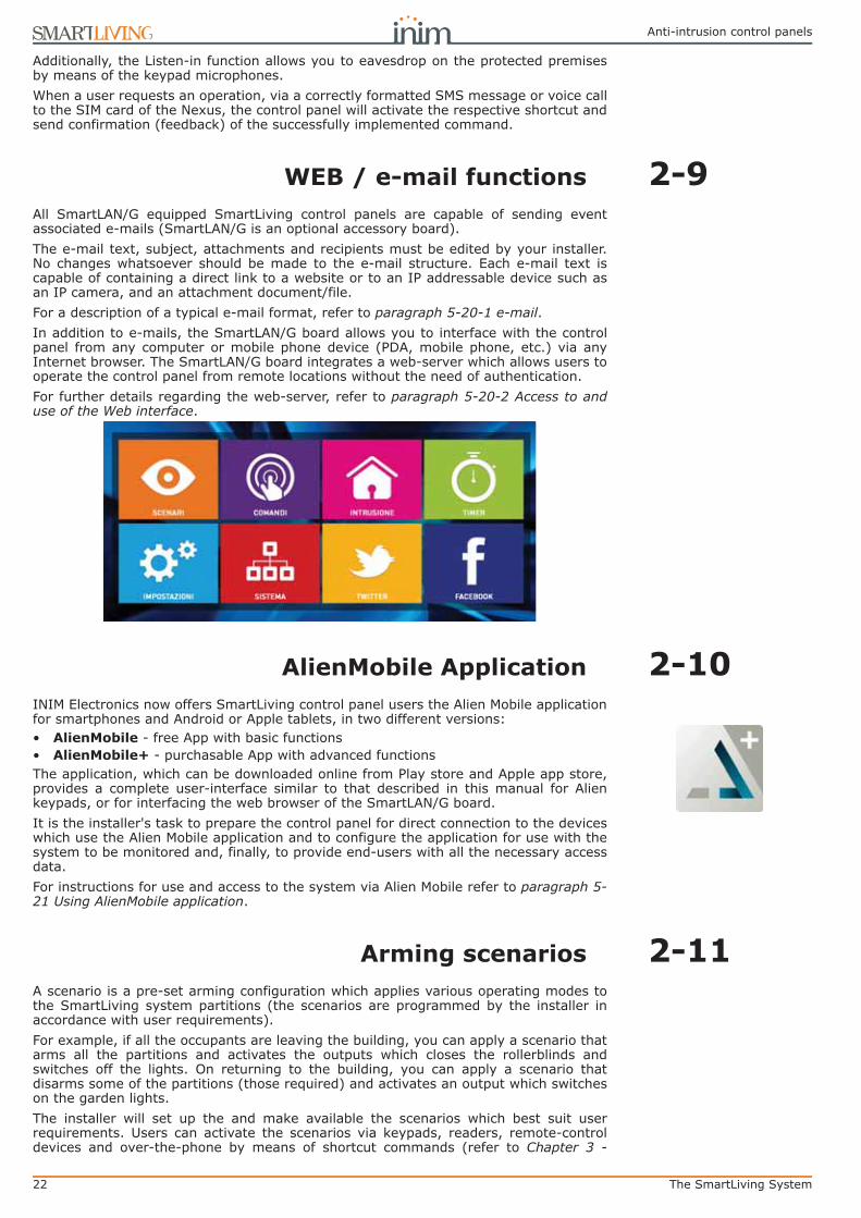
2-10AlienMobile ApplicationINIM Electronics now offers SmartLiving control panel users the Alien Mobile applicationfor smartphones and Android or Apple tablets, in two different versions:• AlienMobile - free App with basic functions• AlienMobile+ - purchasable App with advanced functionsThe application, which can be downloaded online from Play store and Apple app store,provides a complete user-interface similar to that described in this manual for Alienkeypads, or for interfacing the web browser of the SmartLAN/G board.It is the installer's task to prepare the control panel for direct connection to the deviceswhich use the Alien Mobile application and to configure the application for use with thesystem to be monitored and, finally, to provide end-users with all the necessary accessdata.For instructions for use and access to the system via Alien Mobile refer to paragraph 5-21 Using AlienMobile application.
2-11Arming scenariosA scenario is a pre-set arming configuration which applies various operating modes tothe SmartLiving system partitions (the scenarios are programmed by the installer inaccordance with user requirements).For example, if all the occupants are leaving the building, you can apply a scenario thatarms all the partitions and activates the outputs which closes the rollerblinds andswitches off the lights. On returning to the building, you can apply a scenario thatdisarms some of the partitions (those required) and activates an output which switcheson the garden lights.The installer will set up the and make available the scenarios which best suit userrequirements. Users can activate the scenarios via keypads, readers, remote-controldevices and over-the-phone by means of shortcut commands (refer to Chapter 3 -

User’s manual
The SmartLiving System 23
Shortcuts). Scenarios can also be activated via a Web server with an interface formobile phones or PCs, or through the Alien Mobile application by accessing the“Scenarios” section (paragraph 5-2 Arming and disarming partitions).
“SHOW SCENARIO”If the “Show scenario” control panel parameter is active, the left side of the second lineon the screen will display the current scenario.
“VIEW PARTITION STATUS”
If you are using an Alien keypad, the "View partition status" option (refer to paragraph3-3-3 Remote-control shortcuts) will allow you to select the visualization mode of theoperating status on the bottom bar of the display:• Single partition - the characters relating to the operating status of the partitions will
be shown, as described in Table 3: Display visualization• Single scenario - the description of the active scenario will be shownAfter the entry of a valid user code, tapping the bottom bar on the home page will open(for 3 seconds) a window containing a list of the active scenarios.

24 Shortcuts
Anti-intrusion control panels
Chapter 3
SHORTCUTS
3-1Keypad shortcutsThe installer can programme each Joy, nCode and Concept keypad with up to 12shortcuts associated with 4 function keys . The shortcuts areidentified by icons which appear on the lower part of the display. Arrows to the right and
left of the icons indicate that keys , , will allow you to view and use other shortcuts(if programmed).The 12 keypad shortcuts can be activated in 4 different ways, as follows.
1. By ALL. Pressing the respective key , ..., will activate the shortcutinstantly without code entry. The shortcut will affect all the keypad partitions.
2. By ALL with confirmation request. Pressing the respective key , ..., will prompt the system to ask you if you want to continue or not. If you press
the shortcut will activate instantly, if you press or the operation willbe abandoned. This method protects against accidental operations. The shortcutwill affect all the keypad partitions.
3. Code users only. Press the respective key , ..., , then enter a validcode, the shortcut will activate after code recognition. The shortcut will affect thepartitions common to both the keypad and code.
4. Code users only when activation of the shortcut lowers system security.If a shortcut involves a scenario that completely disarms a partition, or switches apartition from Away mode to Stay mode, the security of your system will obvi-ously be at risk, therefore, the system will request code entry. The shortcut willaffect the partitions common to both the keypad and code.
To activate a shortcut, press the key which corresponds to the shortcut icon: , ...,. The system will either activate the shortcut instantly (case 1.) or will request
confirmation (case 2.) or code entry (cases 3. and 4.) before carrying out the operation.
Alien user interfaces do not have function keys , nor do theyprovide access to certain functions via shortcuts. However, the screen provides buttonswhich, with a single tap, activate functions and applications. For further details refer toparagraph 5-19 Alien function keys.
CONTINUE?OK=YES
18:23 01/02/2014DASIDASI--
18:23 01/02/2014DASIDASI--
(1.)
18:23 01/02/2014DASIDASI--
Type in code ******
(3./4.)
Shortcut activation
(2.)
Shortcut activation
Shortcut activation

User’s manual
Shortcuts 25
3-2Shortcut with codeBesides the shortcuts provided by keys , each user code canhave as many as 22 customized (personal) shortcuts.Users will be able to access their code-shortcuts only after validating their PINs (refer toparagraph 2-5-1 Ways of accessing the user menu). Each code can be programmed tomanage:• Up to 12 shortcuts can be activated by keys , ..., and identified by explicit
icons.• Up to 10 shortcuts can be activated by keys , ..., . If a code is enabled to
operate the system over-the-phone, these shortcuts will also be available on thetelephone number-keys.
Entry of a code associated with shortcut no.9: at a Joy/MAX keypad, prompts thevoice announcement of all the shortcuts assigned to the number keys.
Via Keypad1. Validating your PIN2. Access the user menu, using the method described in paragraph 2-5-1 Ways of
accessing the user menu at point 2.3. Press the key , ..., which corresponds to the shortcut icon or press the
key , ..., which is assigned to the shortcut.
“FIXED LENGTH”If the installer has enabled the “Fixed length” option on a user code, the shortcutassigned to F12 will activate as soon as the user types-in their PIN without need oftouching any other key.
Over-the-phone1. Establish communication with the control panel.2. Type in your code followed by “#”.3. Listen to the voice prompts regarding the available shortcuts.4. Press the number key which corresponds to the required shortcut.
3-3Key and Reader shortcuts
3-3-1nBy/S and nBy/XReader shortcuts
Hold a valid key in the vicinity of the reader, as soon as the reader accepts the key, aseries of visual signals on the reader LEDs will indicate the various shortcuts.When the required shortcut is indicated, remove the key to activate the correspondingshortcut action.The visual signals on the Reader LEDs are as follows (refer to Table 11: Reader LEDswith key at reader).
1. Red LED on for 3 seconds - shortcut associated with the red LED of the readeror first shortcut of the key
2. Blue LED on for 3 seconds - shortcut associated with the blue LED of thereader or second shortcut of the key
3. Green LED on for 3 seconds - shortcut associated with the green LED of thereader or third shortcut of the key
4. Yellow LED on for 3 seconds - shortcut associated with the yellow LED of thereader or fourth shortcut of the key
5. All LEDs on for 3 seconds - first shortcut associated with the user key 6. All LEDs off for 3 seconds - disarm all the partitions.7. If the key is not removed, the reader will run through the entire sequence again
starting from the red LED. Selection of the desired shortcut (indicated by a spe-cific LED) will not occur until the key is removed.
If, during this phase, any of the partitions are armed, the LED sequence will start atpoint 6.

26 Shortcuts
Anti-intrusion control panels
“50131READERLEDOFF”If the installer has enabled option “50131ReadLedOFF”, the reader LEDs will be off,therefore, if you wish to activate a shortcut, you must:
1. Wave the key across the sensitive area of the reader: the LEDs will signal therespective status for 30 seconds.
2. During this 30 second period, hold a valid key in the vicinity of the reader in orderto generate the visual signals on the reader LEDs. Remove the key when therequired operation or pre-set scenario is indicated on the LEDs.
3-3-2Shortcuts on the built-in readers ofJoy/MAX and Alien keypads
Users must hold their digital keys in the vicinity of the built-in reader (on the Joy/MAXkeypad, the position of the reader is indicated by , instead, on the Alien keypad it ispositioned on the lower right-hand corner of the frontplate).The key and reader shortcuts will flash one-by-one at 3 second intervals on the keypaddisplay. When the required shortcut is indicated, remove the key to activate thecorresponding action.The shortcuts appear on the display in the following order:
1. Description of the first reader shortcut for 3 seconds2. Description of the second reader shortcut for 3 seconds3. Description of the third reader shortcut for 3 seconds4. Description of the fourth reader shortcut for 3 seconds5. Description of the fourth reader shortcut for 3 seconds6. “Disarm” (disarms all the partitions) for 3 seconds7. Then back to point 1. if the key is not removed.
If, during this phase, any of the partitions are armed, the LED sequence will start atpoint 6.
3-3-3Remote-controlshortcuts
To activate the installer-programmed shortcuts assigned to the 4 keys , ..., onthe remote-control device, simply push the button which corresponds to the desiredcommand. The successful outcome of the operation will be signaled by audible andvisual feedback (refer to Table 12: Feedback signals provided by KF100 wirelessremote-control).
3-4Shortcut listFor the complete list of shortcuts refer to the table in Appendix B, Shortcuts at default.Shortcuts 0 to 8, shown in the table, carry out the specified actions instantly.
Shortcut 9 can be activated over-the-phone only (telephone shortcut).
Shortcut 17 can be activated over-the-phone or at a keypad.
All other shortcuts (from 10 to 16 and from 18 to 37) provide direct access to specifiedsections in the user menu, therefore, can be activated at keypads only.
User keyArm/DisarmScenario 004Partit. notReady
User keyActivate outputCancel
User keyArm/DisarmScenario 003Partitions ready
3 seconds
3 seconds

User’s manual
Voice functions 27
Chapter 4
VOICE FUNCTIONS
If the SmartLiving control panel is equipped with a SmartLogos30M voice board, youwill be able to take advantage of all the voice functions provided by the JOY/MAX andAlien keypads, including the over-the-phone voice guide.Your installer will program the voice messages you require:• for event-associated calls• for event-associated announcements on the keypad at address 1All keypads with voice functions provides a voice memo-box for the recording andplayback of messages. This handy function will allow you to leave messages for otherusers who have access to the keypad; refer to paragraph 5-3 Voice box and intercomfunctions. You can record, play and delete messages at your own discretion.The presence of a new memo in the memo-box will be indicated on the blue LED on thekeypad, as described in Table 7: Keypad LEDs.The SmartLogos30M voice board provides a total of 60 seconds memo time (shared byall the voice-capable keypads in the system).
Note15 memo slots are available.

28 Using the system
Anti-intrusion control panels
Chapter 5
USING THE SYSTEM
This chapter describes all the operations users can carry out with or withoutauthorization (user PIN entry). The tools and methods which allow access the systemoperations are as follows.The system can be accessed:• via Keypad - Joy/GR, Joy/MAX, nCode/G, Concept/G
in which case the user can operate the system in two ways:
1. by means of shortcuts (refer to paragraph 3-1 Keypad shortcuts);2. by means of access codes via the user menu (refer to paragraph 2-5 User Codes
and paragraph 3-2 Shortcut with code). Users have various ways of viewing theirpersonal menus (refer to paragraph 2-5-1 Ways of accessing the user menu).However, this chapter describes only the procedures starting from the menu withvisual information relating to the sections described at point 1 in paragraph 2-5-1Ways of accessing the user menu.
• via Keypad Alien/S, Alien/Gin this case, users are provided with buttons, displayed on the screen, that with asingle tap activate functions and applications. For further details refer to paragraph5-19 Alien function keys.
• via Reader (nBy/X, nBy/S, built-in reader on Joy/MAX and Alien)The proximity-key reader provides users with only one way of accessing the system,as described in paragraph 3-3 Key and Reader shortcuts.
• Over-the-phoneDuring a call from/to the control panel after valid code (PIN) entry.
• Via Command ZoneAfter violation of a duly-programmed zone which sends a command to the controlpanel.
• Via Wireless remote-control deviceby means of keys , ..., , as described in paragraph 2-6-1 Air2-KF100 Wirelesskeyfobs.
• Via Webby means of the integrated web-server on the SmartLAN/G (if installed) via anybrowser (refer to paragraph 5-20-2 Access to and use of the Web interface).
• Via AlienMobile ApplicationIn this case, users are provided with buttons, displayed on the screen of theirsmartphones, which activate functions and applications from remote locations (referto paragraph 5-21 Using AlienMobile application).
5-1Managing alarmsThis paragraph describes the actions users can take during typical alarm and tamperconditions:• Stop alarms - deactivates instantly the outputs activated by zone/partition alarm and
tamper events and system tamper events.The system tamper events are:•• Open panel•• Dislodged panel•• Peripheral tamper (expansion, keypad, reader)•• Peripheral loss (expansion, keypad, reader)
• Clear call queue - clears the outgoing call queue and stops any ongoing calls.• DeleteAlarm mem. - implements a “Stop alarms” operation and, at the same time,
deletes memory of system and partition alarm and tamper events.

User’s manual
Using the system 29
Via KeypadMethod 1Activate the shortcuts associated with keys , ..., shown on the display, withor without code entry:• The shortcut which is assigned to “Alarm menu” menu operations (shortcut n.13:
) allows you to view the respective section. You can select one of the following
options, using keys and and activate it by means of the key:•• Stop alarms •• Clear call queue •• DeleteAlarm mem.
• The following shortcuts activate the associated commands:
•• Shortcut n.2: “Stop alarms”
•• Shortcut n.3: “Clear call queue”
•• Shortcut n.4: “DeleteAlarm mem.”;
Method 2Access the “Alarm management” section (user menu) by means of a valid PIN.Follow the instructions described in Method 1.
Via Alien touch screen
Access the “Menu” section by pressing , type-in the user code and then access the“Actions” section.This section contains a list of control panel commands which can be activated bypressing ON, commands such as:• Stop alarms • Clear call queue • Clear alarm memory
Via ReaderHold a valid key in the vicinity of the reader until the reader LEDs or display indicates"Stop alarms" (shortcut n.2), “Clear call queue” (shortcut n.3) or “DeleteAlarm mem.”(shortcut n.4).
Over-the-phoneType-in the PIN of a user code followed by “#” (the user code must be enabled tooperate the system over-the-phone), then press the key (from “0” to “9”) which theinstaller has programmed to activate “Stop alarms” (Shortcut n.2), “Clear call queue”(shortcut n.3) or “DeleteAlarm mem.” (shortcut n.4).
Via Wireless remote-control devicePush the respective button on the remote-control device and verify the outcome of therequested operation, as described in paragraph 2-6-1 Air2-KF100 Wireless keyfobs.
Via Web and AlienMobileFirst access the “Intrusion” section, then the “Partitions” section.This section contains the list of partitions the user can control, the SET button opens awindow containing a list of commands for the partition. The RESET button deletes
the alarm memory and, if allowed, also tamper memory.
5-2Arming and disarming partitionsYou can arm/disarm the system partitions via keypad, reader, over-the-phone, zonecommand, wireless command, Internet, as follows.If you request an arm-partition command at a keypad (for one or more partitions) andnot all the zones involved are in standby status (thus execution of the command wouldgenerate an instant alarm), the keypad will provide a list of the zones concerned.You can scroll the list and check the zones which are not in standby status (openzones). If you wish to implement the command, the visualized zones will generate aninstant alarm.
User CodeManage alarmsArm/Disarm op.Voice functions
Manage alarmsStop alarmsClear call queueDeleteAlarm mem.
Type in code ******
Method 2
Alarm stopped
Method 2
Method 2
Method 1
18:23 01/02/2014DDDDDDD
Call queue cleared
Memory deleted
Zone not readyPanel T01Panel T02Panel T03

30 Using the system
Anti-intrusion control panels
If you request an arm-partition command at a keypad (for one or more partitions) andconditions (programmed by the installer) which lower the security of the system arepresent, the keypad will provide a list of the conditions concerned, as shown in thefigure opposite.You can scroll the list and view the conditions which lower the security of the system.If you wish to implement the command, you must use a Joy, nCode or Concept keypadand press . Arming the system under such circumstances will generate a “Forcedarming” on partition event. This event highlights the fact that partitions were armedwhen conditions which lowered the security of the system were present (for example,“Low battery” or “Mains failure”). If, however, the installer included the“LossTamp.ongoing” event in the list of conditions which lower security, and thiscondition is active, you can cancel the operation by pressing .
Via KeypadMethod 1Activate the shortcuts associated with keys , ..., (shown on the display) withor without code entry:
• The shortcut which is assigned to “Arm/Disarm” operations (shortcut n.1: )applies the pre-set scenario.
If the shortcut is activated by the entry of a code PIN with the “Fixed Length”attribute, and if all the partitions the user controls are disarmed, they will switchstatus and arm; likewise, if all the partitions the user controls are armed they willswitch status and disarm.
• The shortcut assigned to “Arm/Disarm Menu” (shortcut n.12: ), allows you toview the respective section and arm (in Stay or Away mode) or disarm each partitionseparately.
1. Select the desired partition, using keys and .2. Select the required operating mode for the selected partition, using keys and
.3. Once you have set up the required operations for all the partitions, press .
Method 2Access the “Arm/Disarm” section of the user menu by means of a valid code PIN. Followthe instructions described in Method 1.
Method 3While the entry time is still running (refer to “Entry time” in Appendix A, Technicalterminology and Glossary), type in a valid code (the code must have access to the“Arm/Disarm” section of the user menu), the partitions the code and keypad concernedhave in common will disarm instantly.
Via Alien touch screenThe Alien keypad allow users to activate the programmed scenarios and also set up thearming mode of the partitions they control (have access to):
• Access the “Scenarios” section by pressing . This section provides a list of thescenarios which can be activated by means of the ACTIVATE button.
• Access the “Intrusion” section by pressing , type-in the user code and thenaccess the “Partitions” section.This section displays the partitions separately. You can scroll and select a partitionby means of the right/left scroll keys and then select the arming mode by means ifup/down keys. To apply the selected arming mode press OK.
Via ReaderHold a valid key in the vicinity of the reader and remove it when “Arm/Disarm”(shortcut n.1) is indicated on the LEDs (the system will apply the pre-set scenario).
Over-the-phoneType in a valid code PIN followed by “#”. Press the number key (from “0” to “9”)associated with the “Arm/Disarm” shortcut (shortcut n.1) in order to apply the pre-setscenario.
Faults presentLow batteryTel. line down
18:23 01/02/2014DDDDDDD
User CodeManage alarmsArm/Disarm op.Voice functions
Arm/Disarm op.PARTITION 001 AwayADS-------
Type in code ******
Method 2Armed in
Away mode Method 1
Method 2
Method 2
Method 1

User’s manual
Using the system 31
Via Command ZoneUnder normal circumstances, a command zone comprises a mechanical key-lock or callpoint which activates an electrical contact wired to the command zone. In accordancewith how the command zone is configured, it is possible to:• arm the partitions the zone belongs to• disarm the partitions the zone belongs to• switch the status of the partitions (arm any disarmed partitions and disarm any
armed partitions, refer to “Switch Zone” in Appendix A, Technical terminology andGlossary)
• arm the partitions the zone belongs to when the command zone is violated, anddisarm the partitions the zone belongs to when it restores to standby
Via Wireless remote-control devicePush the respective button on the remote-control device and verify the outcome of therequested operation, as described in paragraph 2-6-1 Air2-KF100 Wireless keyfobs.
Via Auto-arm operationsIf a partition is associated with a timer which controls automatic-arming operations, itwill arm when the timer switches ON and disarm when the timer switches OFF. Userswho are enabled to control Auto-arm operations (refer to paragraph 5-4 Activations)must:• activate the timer associated with the Auto-arm operations• enable the Auto-arm option for the partitions concerned
Via Web and AlienMobileThis method of access allow users to activate the programmed scenarios and also setup the arming mode of the partitions the users can control (have access to):• Access “Scenarios” section This section provides a list of the scenarios which can be
activated by the ON button.The description of the current scenario is displayed on the bar on the bottom left ofthe screen.
• First access “Intrusion” the section and then the “Partitions” section.This section contains the list of partitions the user can control, the SET button opensa window containing the buttons for the arming mode settings.
•• AWAY arming mode arms the perimeter and internal zones and the icon becomes
•• STAY arming mode arms the perimeter zones of the partition and the icon becomes
•• INSTANT arming mode arms the partition in instant mode and the icon becomes
•• DISARM switches off the perimeter and internal zones and the icon becomes
The button indicating the selected arming mode will be highlighted by a different colour to the other buttons.
5-3Voice box and intercomfunctions
Voice communication during keypad-to-keypad intercom calls is one-way, therefore,only one person should speak while the other listens. The user who wishes to speakmust activate the intercom function on the keypad they are using.The voice functions are:• Record - starts the recording phase of the memo in the memo-box of the keypad
you are working on.• Playback - starts the playback phase of the message in the memo-box of the
keypad you are working on.• Delete - deletes the memo in the memo-box of the keypad you are working on.• Intercom - allows voice communication with another voice-capable keypad.
Via KeypadMethod 1Activate the shortcuts associated with keys , ..., (shown on the display) withor without code entry:
18:23 01/02/2014DDDDDDD
IntercomKEYP. 002KEYP. 003KEYP. 004
Ongoing callKEYP. 001OK = ANSWEREsc = END
Caller keypad “KEYP.001” 1
Recipient keypad “KEYP.002” 1

32 Using the system
Anti-intrusion control panels
• The shortcut assigned to the “Voice functions menu” (shortcut n.14: ) allowsyou to view the “Voice functions” section. Select the required function by means of
and then press .•• Record/Playback - the operation time-out (expressed in seconds) will be
signaled by a counter and a progress bar on the display. If you wish to interrupt the record/playback operation manually, press , otherwise, it will end automatically when the pre-set time-out expires. You can adjust the volume during the playback phase using keys and .
•• Delete - this operation must be confirmed by pressing .•• IntercomCall - the display provides the list of keypads you can call. Use
and to select the keypad you wish to contact, then press to start the call. The recipient keypad will emit an audible signal to indicate the incoming call and the display will appear as shown in the figure. The recipient can press to answer the call or to reject it. Both the caller and the call recipient can end the call by pressing . The volume can be adjusted during the listen phase by pressing keys and .
• The “IntercomCall" shortcut (shortcut n.11: ) allows you to view the previouslydescribed “Intercom call" section.
Method 2Access the "Voice functions" section of the user menu by entering a valid PIN code.Follow the instructions described in Method 1.
Via Alien touch screenWhen accessing voice functions via the Alien touch screen, first access the “Apps”section by pressing the button then access the “Voice functions” section.Following is a list of the sections relating to each function which can be activated bypressing the respective ON button:• Record • Play • Delete The sections accessed through the touch screen reproduce the same voice functions asthose previously described for keypads with keys.
5-4ActivationsThe activation/deactivation of the SmartLiving system peripherals and elements(described in the following section) enables them to operate in accordance with theirsettings (activation) or disables their functions completely (deactivation). The user hasfull control over activation/deactivation of the SmartLiving system peripherals andelements.The following section describes the consequences of activation/deactivation.• Zone - disabled zones cannot generate alarms (bypassed).• Auto-arm operations - can be activated/deactivated separately on each single
partition. If this option is enabled on a partition, it will arm and disarm in accordancewith the On/Off settings of the respective timer.
• Codes - deactivated (disabled) codes cannot access the system.Activation/Deactivation can be achieved only on hierarchically inferior codes (refer toparagraph 2-5 User Codes).
• Keys - deactivated (disabled) keys cannot access the system.• Keypads - deactivated (disabled) keypads do not permit code entry (or access to
the menu), therefore, they cannot manage shortcuts. However, the LEDs and displaywill be refreshed.
• Readers - deactivated (disabled) readers cannot provide access to the system,therefore, cannot accept keys or generate commands. However, the LEDs willindicate the current status of the system.
• Timers - activated timers (On) manage their associated elements (partitions, codes,keys) in accordance with their settings. Deactivated timers cannot time-managetheir associated elements, therefore, they will function in accordance with Timer Offstatus.
NoteAll the timers will be activated automatically when you exit the programming session. You mustdeactivate timers which are not used for system control purposes.
• Dialer - a deactivated (disabled) dialer cannot send voice or digital calls. However, ifduly programmed, it will be able to manage incoming calls.
18:23 01/02/2014DDDDDDD
User CodeManage alarmsArm/Disarm op.Voice functions
Voice functionsRecordPlayDelete
Type in code ******
Method 2
Method 2
Method 2
Method 1

User’s manual
Using the system 33
• Answerphone function - if activated (enabled), the control panel will answer incomingcalls with the pre-recorded voice message (“Answerphone message”).
• InternetTeleser. - if activated when the Answerphone option is enabled, thecontrol panel will answer incoming calls with the pre-recorded voice message.
• Teleservice - if activated (enabled), the installer will be able to access the systemvia modem. The teleservice call allows the installer to work on the control panelparameters. Teleservice operations involve a request from you and the installersacceptance, therefore, this option needs to be enabled only when required.
NoteIf the “Answerphone” and “Teleservice” functions are both enabled, the control panel will giveincoming-call priority to the teleservice call. After picking up the call, the control panel will allow theinstaller-company modem 30 seconds to establish communication. If the modem fails to communicatewithin this period, the control panel will play the pre-recorded “Answerphone” voice message.
• Internet access - if this option is enabled, and the system is equipped with aSmartLAN/G board, the control panel will allow user-authorized access to the systemvia LAN/Internet. If this option is disabled, the control panel will allow user-authorized access to the system via teleservice (if authorized).
• Enable install. - if enabled, the Installer PIN will be accepted by the system and theinstaller will have access to the Installer menu. If disabled, entry of the installer PINwill generate an “Invalid Code” event and the installer will be denied access to therespective menu.
• Sync IP2RX - if activated, the control panel will send a specific string to the IP2RXsoftware in order to allow its identification.
Via Keypad
Method 1Activate the shortcuts associated with keys , ..., (shown on the display) withor without code entry:
• The shortcut assigned to the “Activations menu” (shortcut n.15: ), allows youto view the respective section in the user menu, where you can:
1. Use keys and followed by to select the category of elements youwish to activate/deactivate (zones, codes, etc.).
2. Use keys and followed by to select the single element you wish toactivate/deactivate.
3. Use to activate the selected element or to deactivate it.
• Other shortcuts which provide direct access to sub-sections of the “Activations”section are:
•• Shortcut n.19 ( ) accesses “Activations/Zones”
•• Shortcut n.22 ( ) accesses “Activations/Answerphone”
•• Shortcut n.23 ( ) accesses “Activations/Teleservice”
•• Shortcut n.24 ( ) accesses “Activations/Codes”
•• Shortcut n.25 ( ) accesses “Activations/Keys”
•• Shortcut n.26 ( ) accesses “Activations/Timers”
•• Shortcut n.27 ( ) accesses “Activations/Auto-arm”
Method 2Access the “Activations” section of the user menu by means of a valid code PIN.Follow the instructions described in Method 1.
Via Alien touch screen
Access the “Menu” section by pressing , type-in the user code and then access the“Activations” section.Following is a list of the sections relating to the elements you can activate by pressingthe ACTIVATE button. Each section presents its own elements arranged in list form.Each element is associated with two buttons - ON for activation and OFF for inhibition,and an icon which changes in accordance with the status:• - activated/enabled• - deactivated/disabled
18:23 01/02/2014DDDDDDD
User CodeArm/Disarm op.Voice functionsActivations
ACTIVATIONSZonesCodesKeys
Type in code ******
Method 2
Method 2
Method 2
ZONE ACTIVATIONSPanel T01Panel T02Panel T03
Method 1

34 Using the system
Anti-intrusion control panels
Via Web and AlienMobileFirst access the “Intrusion” section, then the “Zones” section.“Zones” section contains a list of the zones available to the user, and each zoneprovides the following keys:
• ON - enables the zone and the corresponding icon becomes
• OFF - inhibits the zone and the corresponding icon becomes
5-5ViewThis section allows you to view the events log and the current status of some of thesystem peripherals and elements.The “Events log”, “Alarms log”, “Faults log” and “Arm/Disarm op.” allow you to view thestart and end of the corresponding events in chronological order.The “Nexus status” section shows (on the display) some of the parameters of the Nexusdialer.The “System voltage” section allows you to view the respective voltage panel.The “Zone Status” section shows the status of the zone (Standby, Alarm, Shorted,Tamper) and its inhibited status (Unbypassed - capable of generating alarms, orBypassed - incapable of generating alarms).The “Faults” section allows you to view current faults only (refer to Appendix C, Faultsignals).The “Panel version” section allows you to view the firmware version and model of yourSmartLiving control panel.When viewing the wireless zones, the last line on the display indicates the level of signalstrength on a scale of 0 to 7; the higher the value the better the signal.If you access the control panel via browser, it will be possible to view the status of:• Partitions• zones• outputs• timer• events log
Via KeypadMethod 1Activate the shortcuts associated with keys , ..., (shown on the display) withor without code entry:
• Shortcut n.28 ( ) accesses “View/Events log”
• Shortcut n.29 ( ) accesses “View/Alarms log”
• Shortcut n.30 ( ) accesses “View/Faults log”
• Shortcut n.31 ( ) accesses “View/Arm/Disarm op.”
User access to the information in the “Logs” is filtered. For example, a user can viewonly the zone alarms relating to the partitions the code and keypad concerned havein common.Use key or to scroll the chronological events list.
For some events, key allows you to view the partitions details. For example, thedetails of an “Arm” command will show the code and keypad concerned and, if youpress , the list of partitions involved.
Zone n.77Standby Unbypsed
PanelVersion
5.10 01050
Method 2
Method 1
User CodeVoice functions ActivationsView
Type in code ******
VIEWEvents logAlarms logFaults log
Valid Code18:23 01/02/2014 PARTITION 001
Valid code18:23 01/02/2014 User CodeKEYP. 001
18:23 01/02/2014DDDDDDDD--

User’s manual
Using the system 35
• Shortcut n.16 ( ) accesses “View/NexusStatus”:
1° line: GSM network provider (Wind, Tim, Vodafone, etc.), on the left side and BUS connections on the right side of the string:- if nothing appears, it means that the Nexus/G is connected to the BUS- if the letter “G” appears, it means that the Nexus/G is connected to the BUS and that the GPRS service is available- if the letter “C” appears, it means that the Nexus/G is connected to the BUS and that a teleservice request (TCP connection) or SIA-IP event report is being sent- if “--” appears, it means that the Nexus is connected to the BUS
2° line: GSM signal reception (value between 1 and 100)3° line: balance, at the last operation (expressed in the local currency)4° line: faults present - access the “View-Faults” section for details.
• Shortcut n.32 ( ) accesses “View/System voltage”
• Shortcut n.33 ( ) accesses “View/Zone status”
Use keys and to scroll the list of accessible zones. The display shows thefollowing zone parameters:
1° line: zone description2° line: zone status (“Standby”, “Alarm”, “Short”, “Tamper”), its activation status (“un-
bypassed” - capable of generating alarms, or “bypassed” - incapable of gen-erating alarms)
3° line: various indications depending on the device type:- wireless zone; wireless signal reception level- level of smoke present in the smoke detection chamber of the Air2-FD100
smoke detector, expressed in mdB/m4° line: level of contamination present in the smoke detection chamber of Air2-FD100
smoke detector (%)
NoteIt is advisable to clean the detector when the value exceeds 90%.
• Shortcut n.36 ( ) accesses “View/Faults”
Method 2Access the “View” section of the User menu by means of a valid PIN. Follow theinstructions described in Method 1.
Via Alien touch screenIt is possible to view the status of the system elements through the various section theuser has access to:
• Access the “Intrusion” section by pressing the button, enter the user code. Thefollowing sections will be available:•• “Zones” - the zones are listed in this section along with their status icons
(positioned to the left of each zone description):• - green spot - standby status• - red spot - alarm status• - yellow triangle - fault/tamper
Each zone is associated with two buttons, ON for activation and OFF for inhibition, and an icon which changes in accordance with the status:• - activated/enabled• - deactivated/disabled
•• “Events Log” - all the events saved to the log are displayed one at a time. However, the up/down keys will allow you to scroll the entire list of events.Each event shows the relative details and, where possible, allows you to view the partitions involved by means of the PARTITIONS button.
• Access the “System” section by pressing the button, enter the user code. Thefollowing sections will be available:•• “Faults” - this section allows you to view all the faults present on the system
and, where possible, the fault details by means of the DETAILS button.•• “Voltage” - this section allows you to view the control panel power-supply
voltage.•• “GSM info” - this section allows you to view the parameters of the Nexus GSM
communicator.
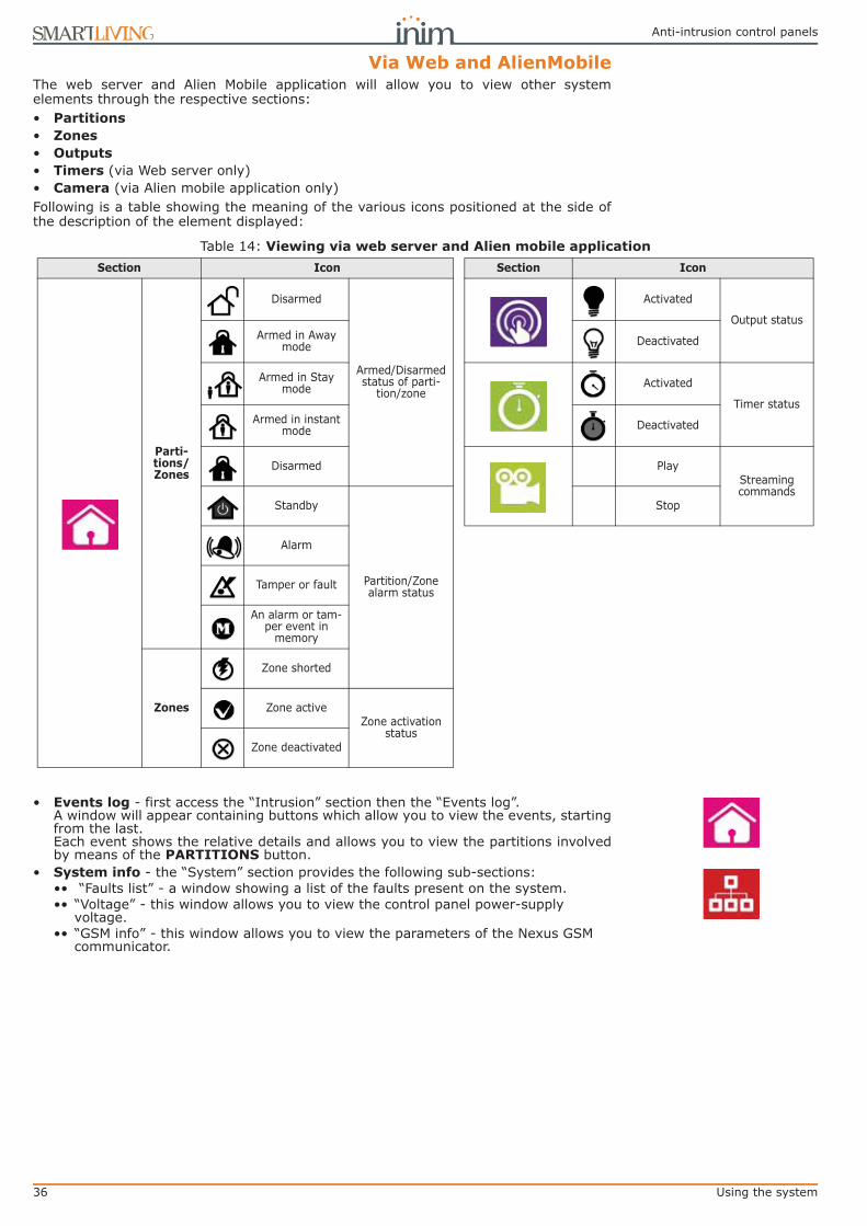
36 Using the system
Anti-intrusion control panels
Via Web and AlienMobileThe web server and Alien Mobile application will allow you to view other systemelements through the respective sections:• Partitions • Zones • Outputs • Timers (via Web server only)• Camera (via Alien mobile application only)Following is a table showing the meaning of the various icons positioned at the side ofthe description of the element displayed:
• Events log - first access the “Intrusion” section then the “Events log”.A window will appear containing buttons which allow you to view the events, startingfrom the last.Each event shows the relative details and allows you to view the partitions involvedby means of the PARTITIONS button.
• System info - the “System” section provides the following sub-sections:•• “Faults list” - a window showing a list of the faults present on the system.•• “Voltage” - this window allows you to view the control panel power-supply
voltage.•• “GSM info” - this window allows you to view the parameters of the Nexus GSM
communicator.
Table 14: Viewing via web server and Alien mobile applicationSection Icon Section Icon
Parti-tions/Zones
Disarmed
Armed/Disarmed status of parti-
tion/zone
Activated
Output statusArmed in Away
mode Deactivated
Armed in Stay mode Activated
Timer statusArmed in instant
mode Deactivated
Disarmed PlayStreaming commands
Standby
Partition/Zone alarm status
Stop
Alarm
Tamper or fault
An alarm or tam-per event in
memory
Zones
Zone shorted
Zone activeZone activation
statusZone deactivated

User’s manual
Using the system 37
5-6Activating/Deactivatingoutputs
This section allows you to activate/deactivate manually the outputs the code is enabledto work on.
Via KeypadMethod 1Activate the shortcuts associated with keys , ..., (shown on the display) withor without code entry:
• The shortcut assigned to “Output control” (shortcut n.21: ), allows you to viewthe “Outputs ON/OFF” section of the user menu where you can:
1. Use keys and to select the output you wish to activate/deactivate.2. Press to activate the selected output or to deactivate it.
• The shortcut assigned to the “Activate outputs” operation (shortcut n.5: ) willactivate the output when the respective button is pressed.
• The shortcut assigned to the “Deactiv. outputs” (shortcut n.6: ) will deactivatethe output when the respective button is pressed.
Method 2Access the “Outputs ON/OFF” section of the user menu by typing-in a valid PIN.Follow the instructions described in Method 1.
Via Alien touch screen
Access the “Commands” section by pressing the button, then select the requiredsub-section:• “Domotics” - accesses the outputs of the home automation system without the need
of code entry.• “Intrusion” - accesses the outputs of the intrusion control system after typing-in a
valid user code.Both sub-sections provides lists of the available outputs, each of which is associatedwith two buttons, ON for activation and OFF for deactivation, and an icon whichchanges in accordance with status:• - output activated• - output deactivated
Via ReaderHold a valid digital key in the vicinity of the reader until the reader LEDs or displayindicates "Activate outputs” (shortcut n.5) or “Deactiv. outputs” (shortcut n.6).
Over-the-phoneType-in the PIN of a user code followed by “#” then press the key (from “0” to “9”)which the installer has programmed to trigger “Activate outputs” (shortcut n.5) or“Deactiv. outputs” (shortcut n.6).
Via Wireless remote-control devicePush the respective button on the remote-control device and verify the outcome of therequested operation, as described in paragraph 2-6-1 Air2-KF100 Wireless keyfobs.
Via Web and AlienMobileAccess the “Commands” section.This section provides a list of the control panel outputs. Each output is associated withtwo buttons:
• ON to activate the output, when activated the corresponding icon becomes
• OFF to deactivate the output, when deactivated the corresponding icon becomes
18:23 01/02/2014DDDDDDD
User CodeActivationsViewOutputs ON/OFF
Type in code ******
Method 2
Method 2
Method 2
Outputs ON/OFFRELAY 001OUTPUT 001OUTPUT 002
Method 1
Output deactivate
Output activated

38 Using the system
Anti-intrusion control panels
5-7Change date and timeThis option allows you to set the date and time in accordance with the selected format.
Via Keypad
Method 1
Activate the “Date/Time” shortcut (shortcut n.35 ), associated with one of the keys, ..., shown on the display, with or without code entry, to access the user
menu at the “Set date/time” section.
1. Use keys and to select the programming field you wish to change (hour, min-utes, etc.).
2. Use keys and to make any changes in the selected field.
3. Press to save the setting.
Method 2Access the “Keypad date/time” section on the User menu by means of a valid PIN.Follow the instructions described in Method 1.
Via Alien touch screen
Access the “Settings” by pressing the , button, type-in a valid user code , thenaccess the “Date/Time - Change PIN - Tel. Numbers” section.This section allows you to access and change the date and time of the control panelclock. Changes can be made using the left/right and up/down scroll keys and confirmedby the OK key.
5-8Keypad settingsThis option allows you to configure the displays and buzzers of the keypads whichaccess to the SmartLiving system.The parameters which are available depend on the type of keypad.• Brightness - for the adjustment of the brightness of the display backlight and key
LEDs when any key is pressed (duration 20 seconds).• Standby brightness - for the adjustment of the brightness of the display backlight
and key LEDs when the keypad is in standby status.• Contrast - for the adjustment of the black/white contrast.• Volume - for the adjustment of the buzzer volume (3 levels available).
•• Off•• Low volume•• High volume
• Keypad options:•• Temperature off - if enabled, the temperature value read by the built-in
temperature sensor will not be shown (only on temperature-sensor equipped keypads).
•• NoExitTimeSignal - if enabled, the buzzer will not emit audible signals during partition Exit time.
•• NOEntryTimeSignal - if enabled, the buzzer will not emit audible signals during partition Entry time.
•• Beep on output - if enabled, the buzzer will emit audible signals during partition Exit time.
•• Disable chime - if enabled, the buzzer will not emit audible signals when a bell zone is violated.
These settings apply only to the keypad you are working on, and will be saved even inthe event of panel shutdown.
18:23 01/02/2014DDDDDDD
User CodeViewOutputs ON/OFFSet date/time
Type in code ******
Method 2
Method 2
Method 2
18:23 01/02/2014dd/mm/yyyy
Method 1

User’s manual
Using the system 39
Via KeypadMethod 1
Activate the shortcut assigned to “Keypad settings” (shortcut n.18: ), associatedwith one of the following keys , ..., (shown on the display), with or withoutcode entry, to access the “Keypad settings” section of the user menu.
1. Use and , followed by to select the parameters to be programmed.2. Use keys and to increase or decrease the value of the selected
parameter. To activate the selected option press , to deactivate it press.
3. Press to save.
Method 2Access the “Keypad settings” section of the user menu by typing-in a valid code PIN.Follow the instructions described in Method 1.
Via Alien touch screen
Access the “Settings” section by pressing the button , type-in a valid user codein order to access the “Alien” section.This section will allow you to view the firmware version of the keypad in use on theconnected control panel and change the parameter settings of the keypad you areworking on.The settings will be saved even in the event of control-panel shutdown.• Transparency - for the adjustment of the transparency effect• Brightness - for the adjustment of screen brightness when touched (duration 45
seconds)• Standby brightness - for the adjustment of screen brightness when the keypad is
in standby status• Volume - for the adjustment of buzzer loudness• Volume voice - for the adjustment of the speaker loudness• Skin - for the selection of one of the skins for the Alien touch screen• Delay photof. - waiting time before the automatic startup of the photoframe
application during standby status• Photo int. - interval between the display of photos used by the photoframe
application• Language - for the selection of the language used by the Alien touch screen
interface• Temperature adjustment - for the adjustment of the temperature shown on the
display• View partitions - for the visualization of the operating status of the partitions on
the bottom bar of the display• Exit time - enables/disables the audible signal during exit time• Entry time - enables/disables the audible signal during entry time• Bell - enables/disables the audible signal for the bell function• Temperature - enables/disables the visualization of the temperature on the display• Tamper - enables/disables the device tamper function (Alien/G only)If the SmartLiving control panel is in maintenance status, a list of the followingparameters will be shown:• Keypad address • Keypad address - this is the address of the Alien keypad and its integrated reader• Tamper - enables/disables the device tamper function (Alien/S only)You can select the parameter by means of “+” and “-”. To confirm changes and exit thesection press SAVE.
NoteEnglish is the default language of the Alien keypad.
5-9Change PINThis section allows you to change the User Code PIN you used for access and also thePINs of other users with a lower rank in the system hierarchy (refer to paragraph 2-5
18:23 01/02/2014DDDDDDD
User CodeOutputs ON/OFFSet date/timeKeypad settings
Type in code ******
Method 2
Method 2
Method 2
Keypad settingsBrightnessBrightnessStdbyContrast
Method 1

40 Using the system
Anti-intrusion control panels
User Codes).In order to be EN50131 compliant, all PINs must have 6 figures.
Via Keypad
Method 1
Activate the shortcut assigned to the “Change PIN” (shortcut n.34: ) andassociated with one of the following keys , ..., (shown on the display), with orwithout code entry, to access the “Change PIN” section of the User Menu.
1. Use keys and followed by to select the user code you wish tochange.
2. Type-in the new PIN (4, 5 or 6 digits) using keys , ..., then press .
3. Type-in the new PIN again using keys , ..., and press to save.
Method 2Access the “Change PIN” section of the user menu by typing-in a valid code PIN.Follow the instructions described in Method 1.
Via Alien touch screen
Access the “Settings” section by pressing , enter a valid user code, then go to“Date/Time - Change PIN - Tel. Numbers” section, then select “Tel.Numbers”.Select the code you desire from those available on the list. The next step is to changethe code using the screen buttons, press OK to confirm.
5-10Change telephone numbersUsers can change the contact numbers used by the dialer of the SmartLiving controlpanel.Only contact numbers with at least one partition in common with the entered PIN andkeypad in use will be shown.
Via KeypadAccess the phonebook:
1. Use keys and to select the required phone number then press ;each programming field accepts a 20 digit phone number.
2. Use keys and to select the field you wish to change, then use the numberkeys ( , etc.) to edit the number. The following characters are also accepted:“,” (= 2 second pause), “*” and “#”.
3. Press to confirm and exit.
Via Alien touch screen
Access the “Settings” section by pressing , enter a valid user code, then go to“Date/Time - Change PIN - Tel. Numbers”, then to the “Tel. Numbers” section.Select the telephone number you desire from those available on the list. The next stepis to change the number using the screen buttons, press OK to confirm.
5-11Teleservice requestThis command sends a call to the installer company.
18:23 01/02/2014DDDDDDD
User CodeDate/TimeKeypad settingsChange PIN
Type in code ******
Method 2
Method 2
Method 2
Change PINCODE 001CODE 002CODE 003
Method 1
Type in code ******
User CodeKeypad settingsChange PINTelephoneNumbers
TelephoneNumbersNUMBER 001NUMBER 002NUMBER 003
18:23 01/02/2014DDDDDDDD--

User’s manual
Using the system 41
Your installer must enable control panel option “Num15ForTeleserv”, otherwise thisfunction will not be available.
Via Keypad
Method 1
Activate theshortcut assigned to the “Teleservice req.” (shortcut n.8: ).
Method 2Access the “Teleservice request” section of the user menu by typing-in a valid code PIN.
Via Alien touch screen
Access the “Menu” section by pressing , type-in the user code and then access the“Actions” section.This section contains a list of control panel commands which can be activated bypressing ACTIVATE, among them is the “Teleservice”.
Via ReaderHold a valid digital key in the vicinity of the reader until the reader LEDs or displayindicates "Teleservice Request" (shortcut n.8).
5-12Overtime requestThis operation can be carried out under the following conditions only.• The partition concerned must be timer-controlled.• The auto-arm option must be enabled (refer paragraph 5-4 Activations).Each overtime request postpones the auto-arming operation by 30 minutes.
Via Keypad
Method 1
Activate the shortcut assigned to the “Overtime” (shortcut n.7: ).
Method 2Access the “Overtime req.” section of the user menu by typing in a valid code PIN.
Via Alien touch screen
Access the “Menu” section by pressing , type-in the user code and then access the“Actions” section.This section contains a list of control panel commands which can be activated bypressing ACTIVATE, among them is the “NEXUS”.
Via ReaderHold a valid digital key in the vicinity of the reader until the reader LEDs or displayindicates "Overtime" (shortcut n.7).
Over-the-phoneType-in the PIN of a user code followed by “#”, then press the key (from “0” to “9”)which the installer has programmed to activate “Overtime” (shortcut n.7).
Via Wireless remote-control devicePush the respective button on the remote-control device and verify the outcome of therequested operation, as described in paragraph 2-6-1 Air2-KF100 Wireless keyfobs.
18:23 01/02/2014DDDDDDD
User CodeChange PINTelephoneNumbersTeleservice req.
Type in code ******
Method 2
Method 2
Service call activated
Method 1
18:23 01/02/2014DDDDDDD
User CodeTelephoneNumbersTeleservice req.Overtime request
Type in code ******
Method 2
Method 2
Auto-arming postponed
Method 1

42 Using the system
Anti-intrusion control panels
5-13ThermostatThe “Thermostat” function, provided by JOY/MAX and Alien keypads, manages theheating or air-conditioning system in accordance with its setting.
• - Summer/Cooling: when the sensor detects that the temperature hasrisen above the value set by the user, the output connected to the air-conditioningsystem will activate (indicated on the display by ).
• - Winter/Heating: when the sensor detects that the temperature hasfallen below the value set by the user, the output connected to the heating systemwill activate (indicated on the display by ).
This function provides 5 operating modes for the user to choose from:• Off - the thermostat is off; the output associated with the heating or air-conditioning
system is deactivated.• Manual - the temperature set by the user is valid for 24 hours per day, for 7 days
per week.• Daily - the temperature set by the user is valid during the selected hours for 7 days
per week.• Weekly - the temperature set by the user is valid during the selected hours on
specific days of the week.• Antifreeze - this is a forced operation. If the temperature drops below 5°C, the
output connected to the heating system will activate.
Via Keypad
Method 1
Activate the shortcut assigned to the “Thermostat” (shortcut n.37: ), associatedwith one of the following keys , ..., (shown on the display), with or withoutcode entry, to access the “Thermostat” section of the user menu.
1. Use the number keys to select the operating mode of the thermostat:
• - thermostat Off• - “Manual”• - “Daily”• - “Weekly”• - “Antifreeze”
The display will show the:1° line: operating mode of the thermostat and day of the week2° line: pre-set temperature gauge and the “Summer/Winter” operating mode icon3° line: temperature setting and operating hours4° line: temperature reading and the status of the heating system/air-conditioning sys-
tem (ON/OFF)
2. Select the operating mode (“Summer/Winter”) of the thermostat using .3. Select the temperature, using keys and .
4. Select the timeframe, using and .5. Select the day of the week, using and .
6. Press to confirm and exit.
Method 2Access the “Thermostat” section of the user menu by typing-in a valid code PIN.Follow the instructions described in Method 1.
Via Alien touch screen
Access the “Climate” section by pressing .The “CLIMA” option will be displayed and the current operating mode of the thermostat.The 5 setting options will be shown below the “CLIMA” title.
18:23 01/02/2014DDDDDDD
User CodeTeleservice req.Overtime requestThermostat
Type in code ******
Method 2
Method 2
Method 1
Week Friday
25.0 c H18-19 18.5 c - OFF -
Off

User’s manual
Using the system 43
Select the button which corresponds to the section you require, then set the parametersof the selected operating mode. You can change the temperature using “+”and “-”, andalso the timeframe and day (where available) by means of the arrow keys.Options for Heat/Cool operations can also be selected for the winter and summeroperating modes.The icons corresponding to the thermostat options are displayed of the upper bar on thehome page.
5-14Teleservice via NexusRequests for teleservice can be made over the GSM network by means of the “NexusTeleserv.” option.This option allows the installer to carry out remote programming operations over theGPRS network.
NoteThis is a service provided by the installer company with the user's collaboration.
Via KeypadAccess the “Nexus Teleserv.” section of the user menu by typing-in a valid code PIN.
Via Alien touch screen
Access the “Menu” section by pressing , type-in the user code and then access the“Actions” section.This section contains a list of control panel commands which can be activated bypressing ACTIVATE, among them is the “Nexus teleserv.” option.
5-15CodesThe user menu provides a section for the programming of the parameters ofhierarchically lower user codes (refer to paragraph 2-5 User Codes).The parameters which can be changed in this section are also available in other sub-sections.
Via KeypadAccess the “Codes” section of the user menu by typing-in a valid code PIN.
1. Use keys and followed by to select the user code you wish tochange.
2. Use keys and followed by to select the parameter you wish tochange.
3. Change the parameter then press to save the changes.
• Description: edit field for the code description.• Partitions - select the partitions the user code is assigned to. Press , to enable
the partition and to disable it.• Options - use and to enable/disable the code options.
•• Partition filter - if this option is enabled, the code will be able to change the parameters only of codes with a lower rank in the system hierarchy whose partitions are amongst the partitions assigned to the code being programmed.For example, if a code is configured as “Master” with “Partition filter” and is assigned to partitions 1, 3, 5 and 7, it will be able to enable/disable or change the PIN of a “User” code assigned to partitions 1 and 5 but not the PIN of a “User” code assigned to partitions 1, 2, and 3.
User CodeOvertime requestThermostatTeleservice Nex-us
User CodeThermostatTeleservice Nex-usCodes

44 Using the system
Anti-intrusion control panels
•• Text menu and User menu - the combination of these two options allows immediate visualization of the menu screens on the keypad displays after acceptance of a valid user PIN. Refer to the following table.
NoteIn all methods of access (A, B or C), the key allows you to access/view the other cases via acircular buffer, see figure.
•• AnnounceShortcut - if enabled on a voice capable keypad, the descriptions of all the shortcuts assigned to the code and associated with the number keys will be announced after acceptance of the entered PIN.
•• Remote access - if enabled, the code PIN can be used to operate the system from any remote telephone.If the code PIN is entered on a remote telephone keypad, only the shortcuts associated with keys 0 to 9 can be used to:- Arm/Disarm- Stop alarms- Clear call queue- Delete memory- Activate output- Deactiv. outputs- Listen-in- Arming statusAny other type of command will have no effect.
•• Patrol - if enabled, the code will be able to disable the system for the pre-set “Patrol time”.
•• Fixed length - if enabled, after typing in a PIN and without pressing the key, the user will be able to activate the shortcut associated with function key “F12”, programmed via the “F1/4KeyShortcuts”, described later.If this shortcut is number 1 (“Arm/disarm”) and all the partitions assigned to the user code in question are disarmed, the command will arm them, otherwise it will disarm them.A user code with this option enabled has access to its own menu only after pressing the key and PIN entry.
• F1/4KeyShortcuts - this section allows you to configure up to 12 shortcutsassociated with keys , ..., . .After valid PIN entry the keypad will show theicons that correspond to keys , ..., and which are associated with theseshortcuts. The respective shortcut will activate when the corresponding key ispressed.
• 0/9 Key shortcuts - this section allows you to configure up to 10 shortcutsassociated with keys , ..., . After PIN acceptance, the code user canactivate the shortcut by pressing the respective number key.
To assign the shortcuts to the function keys, work through the following steps.
1. Use keys and to select the key you wish to associate with the shortcut
then press .
2. Press then, using keys and , select from the “Type” list the shortcutyou wish to associate with the function key.
Case Text menu User menu Description
A Disabled Enabled
Accesses the user-menu (shown as a list of oper-ations the user is enabled to perform); at this
point the user can scroll the list using and and select the required option.
B Disabled DisabledVisualization of the user-icons associated with
function keys , ..., ; at this point the user can press the required function key and acti-
vate the associated shortcut.
C Enabled Disabled
Shows the descriptions of the personalized user-icons associated with function keys. The shortcut descriptions will be shown instead of the shortcut icons, at this point the user can use and
to scroll the list of shortcut descriptions and select the shortcut, which can be activated by
means of the key.
D Enabled Enabled The same as “C”
User Code
User CodeManage alarmsArm/Disarm op.Voice functions
User CodeStop alarmsDelete memoryNexus status
(A)
(B)
(C)

User’s manual
Using the system 45
3. Press to confirm and exit. 4. If the shortcut is associated with “Arm/Disarm” operations, the application will
ask you to select a scenario. If the associated shortcut is “Activate output” or“Deactiv. output”, the application will ask you to select the output.
• ActivatableOutputs - this section allows the user to enable/disable the outputs thecode is allowed to control manually:
User menu, Outputs ON/OFF .
1. Use keys and to select the desired output.2. Use keys and to enable/disable manual control of the output for the
code concerned.
3. Press to confirm and exit.
• Timers - this section allows you to assign a timer to the code. The code will beoperative only at the pre-set times.
• Type - this section allows you to assign a level (rank) in the system hierarchy to theselected code.
• Enablements - this section allows you to enable/disable access to the varioussections of the user menu.The programming steps are identical to those of “Outputs ON/OFF”.
5-16Listen-inThis function can be activated over-the-phone only.Users communicating with the control panel over-the-phone can activate the Listen-infunction and eavesdrop on the protected premises. This is made possible by themicrophones on voice-capable keypads which have at least one partition in commonwith the entered telephone code.Shortcut n.10 must be assigned (by your installer) to one of the number keys relatingto the code that generates this operation.
Over-the-phoneType-in the PIN of a user code followed by “#”, then press the key (from “0” to “9”)which the installer has programmed to activate “Listen-in” (shortcut n.10). The controlpanel will open a listen-in channel between the users telephone and the first voice-capable keypad with at least one partition on common with the entered code. Duringthe listen-in phase, the user can open a voice-communication channel with anotherkeypad by pressing the number key which corresponds to the address of the selectedkeypad. Also in this case, the selected keypad must have at least one partition incommon with the entered code.Press “*”, to end the listen-in phase and step back to the voice-announced Shortcutmenu.
5-17Partition status enquiryThis function can be activated over-the-phone only.The Partition status enquiry function allows users to listen to voice announcementsregarding of the armed/disarmed status of the partitions during telephonecommunications with the control panel, or by activating the corresponding shortcutfrom a voice-capable keypad. The control panel will announce the armed/disarmedstatus of the partitions the entered PIN is assigned to.
NoteIf you activate this shortcut from a keypad, the control panel will announce the armed/disarmedstatus of the partitions the entered PIN is assigned to, regardless of the partitions assigned to thekeypad.
The user code must be enabled (by the installer) to activate shortcut n.17 via keys, ..., or the number keys relative to the code.
Over-the-phoneType-in the PIN of a user code followed by “#” then press the key (from “0” to “9”)which the installer has programmed to activate “Arming status” (shortcut n.17). Thecontrol panel will announce (in order) the descriptions of the partitions the entered PINis assigned to and their current armed/disarmed status.

46 Using the system
Anti-intrusion control panels
Press “*”, to step back to the main menu to listen to all the voice announcementsrelating to the shortcuts assigned to the entered PIN.
Via KeypadAfter entering a valid user-code PIN, press the key which is assigned to the “Armingstatus” shortcut (shortcut n.17). The control panel will announce (in order) thedescriptions of the partitions the entered PIN is assigned to and their current armed/disarmed status.
5-18Commands over-the-phone
5-18-1Panel to user callsYour installer will instruct you as to which events generate voice calls. Event report callswill be sent to the programmed contact numbers of your choice when the event occursand, in most cases, also when it ends.During the call, the call recipient can:• press “*” to go to the next message or, if there is only one message, end the
successful call.• Type-in a valid PIN followed by “#” and access the customized shortcuts assigned to
the code. The control panel will activate the voice guide which will announce theavailable shortcuts and the number keys to press. The respective shortcut willactivate when the key indicated by the voice guide is pressed.
5-18-2User to panel callsIf the “Answerphone” function (refer to paragraph 5-4 Activations) is enabled, users cancall the control panel from any remote telephone and send commands to the system(refer to paragraph 3-2 Shortcut with code) and/or activate Listen-in sessions (refer toparagraph 5-16 Listen-in) in the following way.
1. Dial the control panel telephone number.2. Allow the phone to ring for the pre-established number of rings. The control panel
will answer and will play message n.216.3. Type in your PIN followed by “#”.4. The control panel will activate the voice function which will announce the avail-
able shortcuts and the number keys to press.5. As soon as the selected number is pressed on the telephone keypad, the control panel
will activate the corresponding shortcut.If the system is equipped with a Nexus dialer, the user can operate on the control panelvia voice call to the SIM card of the Nexus. If duly configured (by the installer), the userwill receive feedback (SMS text message or ring) from the Nexus relating tosuccessfully implemented commands.
5-18-3SMS text message tothe user
If the system is equipped with a duly programmed Nexus dialer, the user may receiveSMS text messages signaling that events have occurred.If an event (which has been duly configured by the installer) occurs or restores, thecontrol panel will send notification to the programmed users via SMS.
5-18-4SMS text message tothe control panel
If the system is equipped with a duly programmed Nexus dialer, the user can operate onthe control panel by sending SMS text commands to SIM card of the Nexus.Users who wish to activate a command via SMS text must enter the command detailsas follows:
<xxxxxx> <SMS Text>where:• <xxxxxx> stands for the PIN of a control panel user• a blank space must be keyed in after PIN entry• <SMS Text> which is the command identifier - this parameter must be provided by
your installer.

User’s manual
Using the system 47
If duly configured (by the installer), the user will receive feedback (SMS text messageor ring) from the Nexus relating to successfully implemented commands.
SMS TEXT AT DEFAULTThe SmartLiving control panel is programmed with five predefined default commands:• Balance enquiry relating to the SIM card of the Nexus
If the following SMS text message is sent:<xxxxxx> CREDIT BALANCE
where <xxxxxx> stands for the user's PIN - the user will receive an SMS textmessage indicating the remaining credit (balance).
• Status enquiry relating to the NexusIf the following SMS text message is sent:
<xxxxxx> STATUSwhere <xxxxxx> stands for the user-access PIN - the user will receive an SMS textmessage indicating the:•• device name and firmware revision•• GSM network provider•• GSM signal reception level•• device tamper status•• BUS status•• Balance (remaining credit)
• Inhibition (using the “EXC” or “ESC” command) or activation (using the “INC”command) of the control panel zonesIf the following SMS text message is sent:
<xxxxxx> EXC <zone description>where:•• <xxxxxx> is the PIN of a control-panel user coded, followed by a blank space•• “EXC” (or “ESC” or “INC”) is the command to be implemented on the zone,
followed by a space•• <zone description> is the name zone to be inhibited or activated••
5-19Alien function keysThe Alien touch screen user interface provides a function key menu similar to that ofthe web server of the SmartLAN/G board and the Alien Mobile application. The keys arevisualized as icons which, when tapped, activate the respective functions on the Alientouch screen and Alien Mobile application or, in the case of the web server, when clickedby means of the mouse.The following table provides a description of the function keys displayed on the homepage. The home page of the Alien/S, coincides with the page that is displayed when theuser has not activated any function or application, or has simply not touched the displayfor at least 45 seconds. The keys coincide with those present in the section on the right-hand side of the display of the Alien/G.Some of these keys activate their assigned functions after entry of a user code thatopens a session, which is closed by pressing “Logout” button on the top right of theHome page or after 45 seconds inactivity on the keypad.In the case of the web browser and the Alien Mobile application, this page is displayedafter the user access is achieved via a valid login operation.
Table 15: Alien menu
Icon/keyFunction
Alien keypad Web browser AlienMobile
Scenarios
Accesses the section containing the list of programmed scenarios which can be activated.Refer to paragraph 5-2 Arming and disarming partitions.
No code required for access.Depending on programming, the activation of
scenarios may require code entry./ Available for AlienMobile+ only
Com-mands
Accesses a section containing the list of outputs which can be activated.Refer to paragraph 5-6 Activating/Deactivating outputs.
The outputs are divided in two sections:• “Domotic” outputs for the management of
home automationNo code requested
• “Intrusion” outputs programmed through theintrusion-control systemUser code required.
/ Available for AlienMobile+ only

48 Using the system
Anti-intrusion control panels
Intrusion
Accesses a section which allows you, where possible, to view and change the status of parts of the intrusion-control sys-tem:
• “Partitions” - where it is possible to view and change the status of the partitions.• “Zones” - where it is possible to view and change the status of the zones.• “Events Log” - where it is possible to view the events saved to the events memory (after indicating the number of
events you wish to view).Refer to paragraphs 5-1, 5-2 and 5-5.
User code required.• The “Partitions” section allows you to reset the partition alarm
memory.• The “Events log” section allows you to indicate the number of
events you wish.
Menu
Accesses two sections:• “Actions” - containing a list of the control
panel commands in the event of alarm ortamper events or requests for teleservice andovertime. Refer to paragraphs 5-1, 5-11, 5-12and 5-14.
• “Activations” - where it is possible to view andenable the activations described in paragraph5-4 Activations.
User code required.
Not present Not present
Timer Not presentAccesses a section where it is
possible to view the timers and their status.
Refer to paragraph 5-5 View.Not present
Camera Not present Not present
Accesses a section which allows you to view in real-time the video recording made the camera con-figured in the “Settings” section of the Alien Mobile application.Refer to paragraph 5-5 View.
Available for AlienMobile+ only
Settings
Accesses the sections for the settings of the key-pad and the SmartLiving control panel:
• “Alien” - provides information regarding thesetting-up of the Alien touch screen interfaceyou are using.It shows the model, firmware revision and theaddress of the keypad and built-in reader.Furthermore, it allows you to modify thescreen by means of the + and - keys.Refer to paragraph 5-8 Keypad settings.
• “Date/Time”, “Change PIN”, “Tel.Numbers” -these sections allow you to change the dateand time on the control panel clock, the userPINs and the contact phone numbers saved tothe memory.Refer to paragraphs 5-7, 5-9 and 5-10.
• “Installer” - this section allows access to theinstaller menu after entry of a valid installerPIN, thus putting the control panel inprogramming mode.
User code required.Installer code required for the “Installer”.
Accesses a section where it is possible to:
• select the language of theweb server interface
• upgrade the web serverinterface
• open an online guide
Accesses a section where it is possible to:
• change the settings of theAlienMobile application
• set up a connection with theSmartLiving control panel tobe monitored
• Set the IP address of thecamera viewable in the“Camera” section
System
Accesses a section where it is possible to view the system parts:• List of ongoing faults• Power-supply voltage of the control panel• Information relating the GSM communications board
Refer to paragraph 5-5 View.
User code required. / Available for AlienMobile+ only
Apps
Accesses the applications of the Alien touch screen interface:
• “Photo frame” - application that starts aslideshow of the images contained in theinserted SD-card (see paragraph 5-22 Photoframe).
• “Voice functions” accesses a section where itis possible to activate the control panel voiceboard functions or the “Intercom” function.Refer to paragraph 5-3 Voice box andintercom functions.
No code requested
Not present Not present
Twitter Not present Link to the Twitter page of INIM Electronics.
Table 15: Alien menu
Icon/keyFunction
Alien keypad Web browser AlienMobile

User’s manual
Using the system 49
5-20Using the SmartLAN/G
5-20-1e-mailThe event-related e-mail sent to the user via the SmartLAN/G board must beprogrammed entirely by the installer.Below is an example of an e-mail associated with a “Valid Code” event.
5-20-2Access to and use ofthe Web interface
The security of the connection with the computer is guaranteed by integratedcryptography. The security of the connection of mobile-phone devices is guaranteed bythe SSL protocol used for HTTPS connections.
LOGINFollowing is a description of the method of access to the interface which allows remotemanagement of the control panel.
1. Type in the IP address on the navigation bar of the browser.If you wish to use HTTPS protocol, simply add the letter “s” to the “http” prefix(for example: “http://192.168.1.92” would become “https://192.168.1.92”).
2. At this point the control panel will display the access page template whichrequires the following data (provided by the installer):- Username- Password- Code (user code valid for the control panel)
If the installer code is entered, it will be accepted only if the Teleservice function is enabled (paragraph 5-4 Activations).
3. Press “Login” to start the connection.
ClimateAccesses the thermostat functions section Refer
to paragraph 5-13 Thermostat.No code requested
Not present Not present
Facebook Not present Link to the Facebook page of INIM Electronics
Table 15: Alien menu
Icon/keyFunction
Alien keypad Web browser AlienMobile
Table 16: E-mail parametersOption Example
Subject SmartLiving control panel [Valid code ]
Text, edited by the installer, associated with the respective event (in square brackets).
Sender [email protected] set by the installer
Recipient [email protected], [email protected]
Message text
---------------------2/1/2014 18:23:00
Valid codeCODE 001
KEYP. 005[PARTITION 001]---------------------
The first part of the e-mail shows the date and time of the event (when saved to the events
log) and any relative details.
Access with valid code entry saved to
log. Optional text Link to an Internet website or IP address (if applicable).
http://www.inim.biz
Attach-ment map.pdf Document/file sent with the e-mail
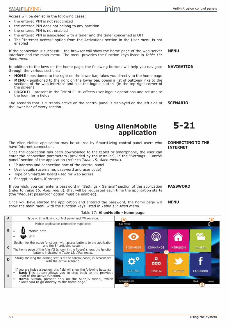
50 Using the system
Anti-intrusion control panels
Access will be denied in the following cases:• the entered PIN is not recognized• the entered PIN does not belong to any partition• the entered PIN is not enabled• the entered PIN is associated with a timer and the timer concerned is OFF.• The “Internet Access” option from the Activations section in the User menu is not
enabled
MENUIf the connection is successful, the browser will show the home page of the web-serverinterface and the main menu. The menu provides the function keys listed in Table 15:Alien menu.
NAVIGATIONIn addition to the keys on the home page, the following buttons will help you navigatethrough the various sections:• HOME - positioned to the right on the lower bar, takes you directly to the home page• MENU - positioned to the right on the lower bar, opens a list of buttons/links to the
sections of the web interface and also the logout button (in the top right corner ofthe screen)
• LOGOUT - present in the “MENU” list, effects user logout operations and returns tothe login form fields.
SCENARIOThe scenario that is currently active on the control panel is displayed on the left side ofthe lower bar of every section.
5-21Using AlienMobileapplication
CONNECTING TO THE INTERNET
The Alien Mobile application may be utilized by SmartLiving control panel users whohave Internet connection.Once the application has been downloaded to the tablet or smartphone, the user canenter the connection parameters (provided by the installer), in the “Settings - Controlpanel” section of the application (refer to Table 15: Alien menu).• IP address and connection port of the control panel• User details (username, password and user code)• Type of SmartLAN board used for web access• Encryption data, if present
PASSWORDIf you wish, you can enter a password in “Settings - General” section of the application(refer to Table 15: Alien menu), that will be requested each time the application starts(the “Request password” option must be enabled).
MENUOnce you have started the application and entered the password, the home page willshow the main menu with the function keys listed in Table 15: Alien menu.
Table 17: AlienMobile - home pageA Type of SmartLiving control panel and FW revision.
B
Mobile application connection-type icon:
• Mobile data
• WiFi
CSection for the active functions, with access buttons to the application
and the SmartLiving system.The home page of the Alien/G (shown in the figure) shows the function
buttons indicated in Table 15: Alien menu.
D String showing the arming status of the control panel, in accordance with the active scenario.
E
If you are inside a section, this field will show the following buttons:• Back This button allows you to step back to the previous
level of the active function.• Home Button, present only on the Alien/S model, which
allows you to go directly to the home page.D
A B
C
E

User’s manual
Using the system 51
5-22Photo frame“Photo frame” is an Alien keypad application that plays a slideshow of images.The image files must be stored in the folder “images” under root on the micro SD cardwhich is inserted in the appropriate slot on the Alien keypad. Visualization image fileformat: JPG, GIF and BMP.
NoteFor optimum visualization, it is advisable to keep the size of each file below 500 kbytes.
There are two ways of starting Photo frame:
• From the Alien keypad - access the “Apps” section by pressing the button ,then press the “Photo frame” button.
• Automatically, if the value set for the “Delay photo” parameter is different from“Disabled”.In order to change this parameter and others of the Alien keypad and theapplication, access the “Settings” section by pressing the button , type-in a
user code and then access the “Alien” section (see paragraph 5-8 Keypad settings).
The slideshow can be stopped by simply tapping the screen, which then returns to thehome page.

52 Technical terminology and Glossary
Anti-intrusion control panels
Appendix A
TECHNICALTERMINOLOGY AND
GLOSSARY
These are 4, 5 or 6 digit PINs which allow the building occupants (users) to access the system.Each code can be programmed to control specific functions only, and to operate the system tosuit the requirements of the Main user.Code types• Installer code: assigned to the installer of the security system• User code: assigned to the end-users of the system
ACCESS CODES
Detection of non-authorized entry into the protected building. More specifically, activation ofalarm signaling devices (detectors).
ALARM
In the event of:• Zone Alarm• terminal tamper• open panel or dislodged panel• peripheral tamper (keypads, expansions, readers)• peripheral loss (keypads, expansions, readers)• false keyThe red LEDs on the system keypads and readers go On each time one of the previously-mentioned events occur. This visual warning signal is held even after the event ends (alarmmemory), in order to warn you that an event occurred during your absence. This visual warningsignal will be held until you clear the event memory (refer to Delete Memory).
ALARM OR TAMPER MEMORY
This is a private service that monitors premises protected by intrusion control systems equipped withdigital or voice dialers.Alarm Receiving Centres receive alarm reports from monitored systems and take all thenecessary actions to protect the occupants of the protected premises.
ALARM RECEIVING CENTRE (ARC)
The “Answerphone” function, if enabled by the user, allows the control panel to answer incomingcalls after a pre-set number of rings. The control panel will pick-up and play the recorded answermessage.During the call, the recipient can type-in a valid PIN (enabled for over-the-phone control) andaccess the authorized functions.
ANSWERPHONE
User operations on one or more partitions. These generally indicate also the status of thepartitions. Under normal circumstances, the zones of armed partitions can generate alarms.Under normal circumstances, the zones of disarmed partitions cannot generate alarms. Thesystem generates tamper alarms even when partitions are disarmed.
ARM/DISARM
You can enable/disable the Auto-arm function on each separate partition.If the auto-arm option is enabled on a timer-controlled partition, the partition will arm/disarm inaccordance with the ON/OFF settings of the timer.
AUTO-ARM
This is the secondary power source of the system. If primary (230 Vac) power failure occurs, thebattery will take over.
BACKUP BATTERY
A list of outgoing event-associated calls the control panel must send to programmed contactnumbers.Enabled users can clear the call queue manually.
CALL QUEUE
Violation of a zone with this configuration will not generate an alarm but will trigger theassociated Timer (Entry time). If the user does not disarm the partition/s within the set “Entrytime”, the system will generate an alarm.For example, the zone that monitors the main door of a building is usually configured as aDelayed Entry Zone, in order to give building occupants time to enter the building and disarm thepartition without generating an alarm.
DELAYED ENTRY ZONE
Violation of a zone with this configuration will not generate an alarm but will trigger the associatedTimer (refer to Exit time).For example, the zone that monitors the main door of a residence or building is usuallyconfigured as a delayed exit zone, in order to give occupants time to leave the partition after anarming operation. If the user does not leave the zone within the set “Exit time”, the system willgenerate an alarm.
DELAYED EXIT ZONE

User’s manual
Technical terminology and Glossary 53
This is an explicit user-command which ends signaling on the red keypad/reader LEDs of thefollowing events:• Zone Alarm• terminal tamper• open panel or dislodged panel• peripheral tamper (keypads, expansions, readers)• peripheral loss (keypads, expansions, readers)• false keyIf you delete the alarm/tamper memory, the visual signals on the red reader/keypad LEDs willclear.
DELETE ALARM/TAMPER MEMORY
This device allows the control panel to send report calls to Alarm Receiving centres (ARC).SmartLiving control panels provide a built-in digital dialer which supports all the most widelyused protocols.
DIGITAL DIALER
The time (expressed in minutes or seconds) that the system allows the user to disarm thepartition after zone violation. It the system is not disarmed within the set time it will generate analarm.Each partition can be programmed with its own Entry time.
ENTRY TIME (OR ENTRY DELAY)
An operative status recognized by the system.For example: detector alarm, mains failure, blown fuse, user-code recognition, etc., are allevents recognized by the control panel.Each event (e.g. mains failure) can be associated with an activation event (when the eventoccurs) and a restoral event (when the event ends).Each event can be programmed to generate the following actions:• activation of one or more outputs• transmission of one or more e-mails• send one or more SMS messages• activation of one or more voice calls• activation of one or more digital calls
EVENT
This is the non-volatile portion of the memory the panels saves events to. The events are savedin chronological order with the following details:• event description - with details regarding new events and restorals• information regarding the user or the cause of event• event location• event date and timeThe events log can be viewed by the system users and the installer.Partition events (zone alarms, partition alarms, arm/disarm operations, recognized codes andkeys, etc.) can be viewed by users with at least one partition in common with the event element.For example, if a user arms several partitions from a keypad, the events log will show:• description of the event - “Arm request”• description of the code and partitions involved• description (label) of the keypad involved• date and time of the request
EVENTS LOG (OR EVENTS MEMORY)
A short period (expressed in minutes or seconds) during which the user must disarm the partitionafter violation (for example, after opening the front door) otherwise the system will generate analarm.Each partition can be programmed with its own Exit time.
EXIT TIME (OR EXIT DELAY)
These boards can be used to increase the number of terminals (zones or outputs) and/or the size ofthe system (in order to extend it over a larger area). Expansion boards can be connected to thesystem via the I-BUS.
EXPANSION BOARDS
A condition which indicates that a system component is not working properly.Some faults can jeopardize the performance of the entire system. Mains failure (230V a.c.),telephone line-down and low battery are typical faults.
FAULT
A device which allows the control panel to make telephone calls over the GSM network and alsoallows users to interact with the control panel over-the-phone or by means of SMS textmessages.
GSM DIALER
This is the two-way communication line (4 wires only) which connects the peripheral devices(keypads, readers, expansions, etc.) to the control panel.The 4 easily identifiable wires, on the control panel motherboard and on the expansions, are:• “+” power 12 Volt• “D” data• “S” data• “-” Ground
I-BUS
A bypassed (disabled) zone cannot generate alarms. Activation/Deactivation of zones can becarried out manually by users or, under certain circumstances, automatically by the controlpanel.
INHIBITION - DEACTIVATION OF A ZONE
The Installer code is generally a 4, 5 or 6 digit PIN that allows the installer to access the systemProgramming Menu either from a keypad or via the respective software programme, on conditionthat all the system partitions are disarmed.
INSTALLER CODE

54 Technical terminology and Glossary
Anti-intrusion control panels
List of system functions and respective parameters accessed via keypad.This menu allows the installer to program, check and change nearly all of the system parameters.The installer menu can be accessed from any keypad after entry of a valid installer PIN, and oncondition that all the system partitions are disarmed, or can be accessed via a computerequipped with the SmartLeague software.
INSTALLER MENU
A zone that monitors the inside of the protected building.For example, the interior zones of an office building are the zones that monitor offices andentrance points.If a partition that a zone belongs to is armed in Stay mode, it will be unable to generate alarms.
INTERIOR ZONE
A portable control device (card or keyfob) which allows the authorized user to access the system.The key must be held in the vicinity of the reader in such a way to allow the system to read it andpermit access to authorized operations.Each key is programmed with:• A random code selected from over 4 billion possible combinations.• A label (usually the name of the user).• The partitions it controls (arms, disarms, etc.).• A group of pre-set parameters which allow the key user to operate the system in accordance
with the authorized access level (for example, a key can be programmed to arm or disarm thesystem only at certain times of the day).
KEY
This device allows users to access and control the system. Keypads can be connected to thesystem via the I-BUS.The keypad allows users to access and control the partitions which are common to both the codeand keypad in use. The user can arm/disarm partitions, view the status of the zones, stop visualand audible signaling devices.
KEYPAD
A generic magnetic-contact is a detector/sensor based on an magnet which, when placed nearthe sensor, provokes the mechanical closure of an electrical contact.
MAGNETIC CONTACT
An electrical output point connected to a signaling or control device activated/deactivated by thecontrol panel in response to programmed events.
OUTPUT
Signaling that may be associated with a state of emergency perceived by the user and signaledto the intrusion control panel by means of a button or the activation of a shortcut.This type of signaling generates an event which activates the programmed outputs and calls. Thistype of signaling does not activate the red LEDs on the keypads and readers nor is it visualizedon the keypad displays.
PANIC
A group of zones.A partition identifies a group of zones that belong to a spatial or logical portion of the protectedpremises. For example, a partition may comprise all the zones that protect the downstairspartition of a house (spatial partition), or all the entrances of an office building (logical partition).
PARTITION
This refers to the status of a partition as requested by the user.The user can carry out the following operations.• Disarm - this operation disables the partition completely. In this way, none of the zones
belonging to the partition can generate alarms.• Away mode - this operation enables the interior and perimeter zones of the partition. In this
way, all of the zones of the partition can generate alarms.• Stay mode - this operation enables only the perimeter zones of the partition. In this way,
only the perimeter zones of the partition can generate alarms.• Instant mode - this operation enables the partition perimeter zones only and annuls delays.
In this way, violation of the perimeter zones of the partition will generate instant alarms.• Hold - this operation forces the partition to hold its current status.
PARTITION ARM/DISARM OPERATIONS
A periodic inspection of the protected premises carried out by authorized security staff. PATROLA zone that monitors the entrance points of the protected building.Perimeter zones are usually direct entrance points such as doors and windows. For example, thefront door of an apartment and windows that allow access from outside.
PERIMETER ZONE
Devices connected to the control panel via the I-BUS.SmartLiving control panels manage the following peripherals:• Keypads (Joy, nCode, Concept, Alien)• Proximity Readers (nBy)• Expansions (Flex5)• Transceiver (Air2-BS100)• Sounderflashers (Ivy)• Isolators (IB100)• GSM dialer (Nexus)
PERIPHERALS
The period (expressed in minutes) before an automatic arming operation.For example, if a partition is set to arm automatically at 10:30 with a Pre-arm time of 5 minutes,all the partition keypads and readers will initiate an audible countdown at 10:25 in order to warnusers of the forthcoming arming operation.Each partition can be programmed with its own Pre-arm time.
PRE-ARM TIME
The installation site.Identifies the building or part protected by the intrusion control system, generally, a house oroffice.
PREMISES

User’s manual
Technical terminology and Glossary 55
Under normal circumstances, the mains power supply (230Vac) 50 Hz (110V a.c. 60Hz in somecountries).Usually connected to a switching power supply or transformer (depending on the model) thatprovides the stabilized voltage to the system and the charge source to the batteries.
PRIMARY POWER SOURCE
This device allows users to access and control the system. The system readers are connected tothe control panel via the I-BUS.The readers allows users to arm/disarm the partitions which are common to both the reader andkey in use (refer to Shortcuts). The key (TAG) must be held in the vicinity of the reader in such away to allow the system to read it and permit access to authorized operations. Although readersprovide a more limited access to the system, they are easiest way of carrying out day-to-dayoperations (arm, disarm, etc.).
READER
A pre-set arming configuration which applies various operating modes to the system partitions. SCENARIOThe shortcuts allow direct access to the user menu sections and various operations whichnormally require several steps inside the user menu.
SHORTCUTS
Optical smoke detectors are equipped with sampling chambers (based on light scattering mass -Tyndall effect). They are capable of sensing the presence of smoke particles and thus detecting afire in its early stages.These detectors have low power absorption during standby. The current absorption increasesduring alarm status and thus signals the danger of fire to the control panel.
SMOKE DETECTORS
The “supervision time” is the interval during which the wireless-system devices (in general wirelessdetectors in permanent placements) must signal to the control panel that they are operating in thenetwork. If a wireless device fails to signal before the “supervision time” expires, it will be classifiedas “Lost” and the control panel will trigger a “peripheral-loss” fault event.
SUPERVISION
Detection of a serious condition that jeopardizes the operating capacity of the device concernedand thus puts the system at risk.Tamper conditions are detected by tamper switches connected to the system zones, keypads,readers, expansions and control panel. Generally, these events are triggered by system violationsuch as unauthorized opening of a keypad cover.
TAMPER
These are calls sent to programmed contact numbers when specific events start and end(restoral).
TELEPHONE ACTIONS
This is a service provided by the installer company with the user's collaboration. The installerconnects to the control panel over-the-phone or via a GPRS or Internet connection and, in thisway, can check and/or change the control panel programming data.
TELESERVICE
A zone with this attribute cannot generate alarms (activate audible and visual signaling devices).However, any alarm events that occur will be saved to the events memory.If zones are not operating properly, the “Test” option will allow the installer to check themwithout the risk of generating false alarms
TEST ZONE
A logical entity for automatic time-management of programmed peripherals or elements.SmartLiving control panels provide 10 timers.
TIMER
Transceiver-equipped devicesIn two-way wireless systems, all the devices are equipped with transceivers. In one-way wirelesssystems, the main unit is equipped with a receiver module whereas the peripheral devices areequipped with transmitters.
TRANSCEIVER
Each code is programmed with:• A 4, 5 or 6 digit PIN which allows access the system.• A label which identifies the user (usually the user's name).• The group of partitions it controls (arms, disarms, etc.).• A group of pre-set parameters which allow the operator to work on the system in accordance
with its authorized access level (for example, a code can be enabled to consult the events logbut not to change the date and time).
• A hierarchical level, that may allow the user to change to parameters of codes on a lower level in the system hierarchy.- User (the lowest level)- Manager- Master
USER CODE
List of functions available to the user after entry of a valid code at the keypad. USER MENUThis device allows the control panel to send voice calls to programmed contact numbers.In SmartLiving control panels the voice dialer function is provided by the SmartLogos30M board(accessory item).
VOICE DIALER
If the system is equipped with a SmartLogos30M voice board, all keypads with voice functionspresent in the system configuration will allow users to record memos. Messages can be recorded,played and deleted as required.
VOICE MEMO
An intrusion control system whose devices (detectors, keypads, keyfobs) communicate with thecontrol panel over radio waves.Usually, only the control panel of wireless-systems is mains powered (220Va.c.) while, thewireless devices are battery powered. The battery life is of utmost importance in the designlayout and operational capacity of these systems.
WIRELESS
An electrical input point used for the management/supervision of signals coming from anintrusion detection device.
ZONE

56 Shortcuts at default
Anti-intrusion control panels
Appendix B
SHORTCUTS AT DEFAULT
n. Icon description function parameter n. Icon description function
1 Arm/Disarm Applies a pre-set scenario which sce-nario 20 Voice memo Accesses the user menu
section: Voice functions
2 Stop alarms
Immediately deactivates the outputs relative to
zone/partition alarm and tamper events and system
tamper events.
21 Output control Accesses the user menu section: Outputs ON/OFF
3 Clear call queueCancels the entire call
queue and stops ongoing calls (if any).
22 Enab.answer-phone
Accesses the user menu section: Activations/
Answerphone
4 Delete memory
Carries out a “Stop alarms” operation and, at the same time, deletes memory of
system and partition alarm and tamper events.
23 Enab.teleserviceAccesses the user menu section: Activations/Tele-
service
5 Activate output Activates one of the pro-grammed outputs. Output 24 Enable codes Accesses the user menu
section: Activations/Codes
6 Deactiv. outputs Deactivates one of the pro-grammed outputs. Output 25 Enable keys Accesses the user menu
section: Activations/Keys
7 Overtime Delays auto-arming time of partitions by 30 minutes. 26 Enable timers Accesses the user menu
section: Activations/Timers
8 Teleservice req.Sends a call to the Installer company number (Teleser-
vice number).27 Enab. auto-arm
Accesses the user menu section: Activations/Auto-
arming
9 Voice menuPlays a recorded voice mes-sage which announces the shortcuts assigned to the
number keys.User code 28 View events log Accesses the user menu
section: View/Events log
10 Listen-inAllows eavesdropping over-the-phone by means of a
microphone located on suit-ably placed keypad.
Keypad 29 View alarm log Accesses the user menu section: View/Alarms log
11 Intercom CallAccesses the user menu section: Voice functions/
intercom Call30 View faults log Accesses the user menu
section: View/Faults log
12 Arm/disarm menu
Accesses the user menu section: Arm/Disarm 31 View arm ops log
Accesses the user menu section: View/Arm/Disarm
op.
13 Alarm menu Accesses the user menu section: Manage alarms 32 ViewSystemSta-
tusAccesses the user menu
section: View/System sta-tus
14 Voice func. menu
Accesses the User Menu section: Voice functions 33 View zone status Accesses the user menu
section: View/Zone status
15 Activations menu
Accesses the user menu section: Activations 34 Change PIN Accesses the user menu
section: Change PIN
16 View Nexus sta-tus
Accesses the user menu section: View/Nexus status 35 Time/Date Accesses the user menu
section: Time/Date
17 Arming statusProvides voice information regarding the armed/dis-armed status of the parti-
tions.36 View faults Accesses the user menu
section: View/Faults
18 Keypad sett.menu
Accesses the user menu section: Keypad settings 37 Thermostat
menuAccesses the user menu
section: Thermostat
19 ZoneBypass menu
Accesses the user menu section: Activations/Zones 19 38 Panic Activates a “Panic” event

User’s manual
Fault signals 57
Appendix C
FAULT SIGNALS
The following table shows the system faults which are signaled on the yellow LED on thekeypad :
DCM
UIN
E0SLI
VIN
GE-
R51
0-20
1402
24
FAULT Message on the User menu, “View/Faults” Probable cause Note
Zone fuse blown Zone fuse fault Excessive current draw on the “+AUX” terminals of the control panel
BUS fuse blown IBUS fuse fault Excessive current draw on the “+” terminal of the control panel
Backup battery ineffi-cient or not connected Low battery The backup battery of the control panel is almost
empty or disconnected.Primary power-source
loss Mains failure The primary power source voltage (230 Vac) has failed or has been disconnected
The PSTN landline is unavailable Tel. line down Trouble on the PSTN landline
Interference Jamming Wireless transmission is poor
Wireless detector bat-tery low Low battery WLS
The battery of at least one wireless detector is running out
To view “LowBatt. battery WLS” and “WLS zone loss” signaling, access the user menu, go to
“View/Faults”, press to view the list of devices involved.
Wireless detector not operative WLS zone loss At least one wireless detector is not operating
Nexus GSM dialer faults
Nexus fault / Low signal
The GSM network signal is insufficient
Press on “Nexus fault” to access the list of current faults.
Nexus fault / GSM module fault
The GSM module of the Nexus dialer is not oper-ating properly. Call your Installer company
Nexus fault / SIM commun.fault
The SIM card does not respond or is not present.The SIM card PIN is not disabled.
Nexus fault / Low Credit
The credit left on the SIM card is below the mini-mum credit threshold.
Nexus fault / Pro-viderUnavailable
The GSM network provider of the SIM in use is unavailable.
Nexus fault /GPRS conn. lost
NEXUS/G detects problems on GPRS network communications
IP connection loss IP conn. lost The verification of the IP connection fails.
Device loss or tamper in progress LossTamp.ongoing
One of the following events has occurred:• Control panel open• Dislodged panel• Expansion tamper• Keypad tamper• Reader tamper• Sound.flash.Tamp• Expansion loss• Keypad loss• Reader loss• Sound.flash.Loss
Faults on IVY-BUS sounderflasher
Sounder faults / Horn fault
A defect/damage has been detected on the horn/sounder.
Press on “Sounder faults” to access the list of devices which have at least one fault present.
Press on the selected sound-erflasher to access the list of cur-
rent faults on the device concerned.
Sounderflasher faults / LowBatt.Soundfl.
A low-voltage value has been detected on the sounderflasher battery.
If the voltage drops below 10V, the device will inhibit the sounder and activate only the flasher (in the event of an alarm). If the voltage drops
below 8V, the device will inhibit both the sounder and the flasher.
Sounderflasher Faults / Battery resist.
An excessive internal resistance has been detected on the sounderflasher battery. This type of deep fault indicates corrosion inside the bat-tery, therefore, the battery must be replaced.
Violation of zones with faults Faults on zones Violation has occurred on one or more zones
with the “Fault zone” option enabled.Press to access the list of
zones involved.Contaminated smoke sensor Detector dusty
The smoke chamber of at least one of the Air2-FD100 smoke detectors is contaminated by dirt
or dust.

58 Fault signals
Anti-intrusion control panels

Installation and programming manual
59
Notes

60
Anti-intrusion control panels
Azienda certifi cata ISO 9001: 2008
via Fosso Antico Loc. Centobuchi63076 Monteprandone (AP) ITALYTel. +39 0735 705007 _ Fax +39 0735 704912
[email protected] _ www.inim.biz FM 530352
ISO 9001:2008 registered company