Manual XT-360 L - extremausa.com · Direction of Rotation 9 Speed Selection ... The machine was...
57
XT XT XT XT- - -360(L) 360(L) 360(L) 360(L) EXTREMA MACHINERY COMPANY, INC EXTREMA MACHINERY COMPANY, INC EXTREMA MACHINERY COMPANY, INC EXTREMA MACHINERY COMPANY, INC PO BOX 1450, ALBANY, LOUISIANA 70711 PO BOX 1450, ALBANY, LOUISIANA 70711 PO BOX 1450, ALBANY, LOUISIANA 70711 PO BOX 1450, ALBANY, LOUISIANA 70711 (877) 398 (877) 398 (877) 398 (877) 398- - -7362 (225) 567 7362 (225) 567 7362 (225) 567 7362 (225) 567- - -2966 FAX 2966 FAX 2966 FAX 2966 FAX
Transcript of Manual XT-360 L - extremausa.com · Direction of Rotation 9 Speed Selection ... The machine was...

XTXTXTXT----360(L)360(L)360(L)360(L)
EXTREMA MACHINERY COMPANY, INCEXTREMA MACHINERY COMPANY, INCEXTREMA MACHINERY COMPANY, INCEXTREMA MACHINERY COMPANY, INC PO BOX 1450, ALBANY, LOUISIANA 70711PO BOX 1450, ALBANY, LOUISIANA 70711PO BOX 1450, ALBANY, LOUISIANA 70711PO BOX 1450, ALBANY, LOUISIANA 70711
(877) 398(877) 398(877) 398(877) 398----7362 (225) 5677362 (225) 5677362 (225) 5677362 (225) 567----2966 FAX2966 FAX2966 FAX2966 FAX

1
TABLE OF CONTENTS Machine Identification 3 Notes for User 3 Specifications 4 Noise Level 5 Safety Warnings 5 General Safety Rules 6 Specific Safety Rules 7 Safe Working Practice 8 Operator Training 8 Stability 8 Machine Setting & Adjustment 8 Handling of Tools 8 Setting the Tool in the Machine 8 Fence Adjustments 8 Direction of Rotation 9 Speed Selection 9 Machine Operation, Guard Selection & Adjustment 9 Straight Work Where the Molding Extends Over Full Length of Work Piece 9 Stopped Work 10 Curved Work 10 Bevel Cutting 10 Climb Cutting 10 Other Work 10 Use of Safety Appliances 10 Noise Reduction 11 Warning Labels 11 Unpacking & Cleanup 12 Unpacking 12 Transportation After Unpacking 12 Cleaning the Machine 12 Installation & Leveling 13 Electrical Safety Rules 13 Grounding Information & Power Connections 14 Control Unit 15 Electrical Controls 15 Speed Change & Belt Adjustment 16 Guide Values for Cutting Speed 16 Spindle Lock 18 Basic Type 18 Standard Type A 18 Standard Type B 19 Lock Pedal 19 Interchangeable Spindle with Draw Bar 20
For Interchangeable Spindle with Draw Bar 20 For Interchangeable Spindle without Draw Bar 20
Spindle Vertical Travel Adjustment 22

2
Type A 22 Type B 22 Type C 23 Spindle Tilting Adjustment 24 Forward Tilt Type 24 Backward Tilt Type 24 Assembly Cutters to Spindle 25 Table Rings 25 Assembling & Installing Fence & Dust Hood 26 Assembling Fence 26 Assembling Guards to Fence Body 26 Fence Controls & Adjustments 27 Assembling Dust Hood 27 Assembling Miter Gauge & Clamp 28 Assembling Miter Gauge 28 Assembling Stop Rod/Fence & Stop to Miter Gauge 29 Miter Gauge Clamp 29 Stop Fence for Sliding Table (Optional) 29 Sliding Table Adjustment (for Sliding Table Only) 30 Sliding Table Lock 30 Installing Tenoning Hood (Optional) 30 Set-Up & Operation of Control System 31 Control Panel/Function of Keys 31 Power Connections 32 Enter a New Spindle Height Setting 32 Checking Settings Already Set-Up in System 32 Setting Zero Reference Point 32 Automatic Operation 33 Warning Signal 33 Presetting Parameter 33 Straight Work Operations 34 Position of Collars 35 Tenoning Operations 36 Curved Work 36 Machining with Jig (Copying) 36 Machining without Jig 36 Lubrication 37 Periodical Maintenance 37 Troubleshooting 38 Parts 40

3
MACHINE IDENTIFICATION Machine model and serial number are punched onto a metallic plate placed on the machine frame (refer to Fig. 1). For information concerning specifically the electric system you must specify the data punched on the metallic plate.
NOTES FOR THE USER The machine was designed for shaping, tenoning wood as well as wood material; therefore the user is responsible for any damages due to the different use of the machine. The handbook describes all the operations usually required for the machine maintenance. Do not carry out operations not described in the handbook. Only authorized technicians should carry out operations that require the demounting of machine members as well as maintenance operations.

4
SPECIFICATIONS
Spindle Shaper XT-360/XT-360L
Dimension of working table 850mm x 1300mm
Dimension of extension table 850mm x 2500mm
Spindle vertical stroke 250mm
Max tool diameter: Below table top Above table top
320mm 360mm
Spindle speed 3000/4000/6000/8000/10000 RPM
Motor power 10 HP
Net weight 1640 lbs/ 1860 lbs

5
NOISE LEVEL
Measurement of the Sound Emission
Measured according to prEN848-1:1994
Utilization: Free Running
Background Noise LWA Declaration Constant K
57.5dB 78.1dB 4dB
The figures quoted for noise are emission levels and not necessarily safe working levels. Whilst there is a correlation between emission levels and exposure levels, this cannot be used reliably to determine whether or not further precautions are required. Factors that influence the actual level of exposure to the work force include the duration of exposure, the characteristics of the workroom, other sources of dust and noise, etc., for example, the number of machines and other adjacent processes. Also the permissible exposure levels can vary from country to country. This information, however, will enable the user of the machine to make a better evaluation of the hazard and risk. SAFETY WARNINGS Woodworking can be dangerous if safe and proper operating procedures are not followed. As with all machinery, there are certain hazards involved with the operation of the product. Using the machine with respect and caution will considerably lessen the possibility of personal injury. However, if normal safety precautions are overlooked or ignored, personal injury to the operator may result. Safety equipment such as guards, push sticks, hold-downs, feather boards, goggles, dust masks and hearing protection can reduce your potential for injury. But even the best guard won’t make up for poor judgment, carelessness or inattention. Always use common sense and exercise caution in the workshop. If a procedure feels dangerous, don’t try it. Figure out an alternative procedure that feels safer. Remember, your personal safety is your responsibility. This machine was designed for certain applications only. We strongly recommend that this machine not be modified and/or used for any application other than that for which it was designed. If you have any questions relative to a particular application, do not use the machine until you have first contacted us to determine if it can or should be performed on the product.

6
GENERAL SAFETY RULES There is a certain amount of hazard involved with the use of woodworking machinery. Using the machine with the respect and caution demanded as far as safety precautions are concerned will considerably lessen the possibility of personal injury. However, if normal safety precautions are overlooked or ignored, severe personal injury to the operator can occur. 1. Read the operation manual before operating this machine. 2. If you are not thoroughly familiar with the machine operation, obtain advice from a
supervisor or other qualified person. 3. The machine should be disconnected from the power source before performing
maintenance or adjustments to the internal mechanisms, or when making repairs. 4. After maintenance job is finished, check to see if there are any tools or objects left on the
machine. Close all safety guards. 5. Before leaving the machine, make sure the work area is clean. 6. Check timber for loose knots, nails, or other items, which may cause a hazard or affect the
machine’s performance. 7. Learn the machine’s applications and limitations, as well as the specific potential hazards
peculiar to it. Keep the machine in top condition for best and safest performance. 8. Keep all guards in place and in working order. 9. Do not force the machine. It will do the job better and be safer working at the rate for which
it was designed, 10. All children and visitors should be dept a safe distance from the working area. 11. The operator should keep proper footing and balance at all times. 12. Do not operate the machine while under the influence of drugs, alcohol, or any other
medication. 13. Avoid awkward operations and hand positions where a sudden slip could cause your hand
to move into the cutterhead. 14. Never leave the machine until it comes to a complete stop, and never leave the machine
running unattended. 15. The employer is responsible for selecting for selecting competent and qualified employees. 16. The employer must make sure that employees study and utilize this safety information. 17. Supervisors must alert personnel of any unsafe practices they observe. 18. All employees should be aware of first aid facilities and be encouraged to use them,
regardless of the severity of the injury. 19. Fire prevention must be practiced and fire protection must be available to prevent loss of
life, personal injury, and property damage. 20. Safety shoes should be worn to provide protection against rolling objects, falling objects,
and sharp edges in the workplace. 21. Eye protection should be worn and such devices should be carefully selected, fitted and
used. Compulsory wearing of glasses with impact resistant lenses and side shields is a good safety policy. All eye protection should conform to ANSI 87 standards.
22. Wear hearing protection when operating the machine. 23. Do not wear rings, necklaces or jewelry around moving machinery. 24. Do not wear loose fitting clothes. Clothing should be comfortable, but long sleeves,
neckties, etc. should not be worn. 25. Do not wear gloves or other hand covering articles around moving machinery. 26. Cover long hair with a hair net or cap.

7
27. Protective guards and shields must be in place at all times unless they must be removed for specific service or maintenance. They should be immediately replaced when service or maintenance is completed.
28. Make sure that operator clearly knows how to stop the machine before starting work. 29. Never clean or remove chips while the machine is running. 30. Maintain the machine in good operating condition. Report unusual conditions or machine
malfunctions immediately. 31. Do not alter or remove guards and warning labels. 32. Keep the immediate area clean. Do not allow the floor to become slippery, or covered with
dust or obstacles. Dust that accumulates in the work area is a hazard that can cause you to fall or slip against the machine or its controls.
33. Employees should be required to report to their supervisors any hazardous condition of the machine or in the immediate area.
SPECIFIC SAFETY RULES 1. Never run the stock between the fence and the cutting tool. 2. The fence halves should be adjusted endwise so the opening is never more than is
required to clear the cutter. 3. The cutter should be positioned below the work piece whenever possible. This lessens the
possibility of injury or a damaged work piece, which could occur if the work piece becomes trapped between the cutter and table.
4. Always use the miter gauge and clamp attachment when edge shaping work less than 150mm wide.
5. Make sure the keyed washer is positioned directly under spindle nut and that spindle nut is securely tightened before operating.
6. Do not use awkward hand positions. 7. Make certain spindle lock is released before starting machine. 8. When shaping with collars, the cutter should be positioned below the collar whenever
possible. 9. Check speed setting to make sure it is proper for the cutter and work piece. 10. Always feed work piece against the cutter rotation. 11. Make sure spindle draw bar and draw bar nuts are securely tightened before operating. 12. Turn the main switch to zero, indicate so with a sign and padlock the main switch before
making all adjustments or servicing.
8
SAFE WORKING PRACTICE Operator Training It is essential that all operators of vertical spindle shapers are adequately trained in the use, adjustment and operation of the machine, this covers in particular:
1. The dangers associated with the operation of the machine. 2. The principles of machine operation, correct use and adjustment of the fence, jigs and
safeguards. 3. The correct selection of tools for each operation. 4. The safe handling of the work piece when cutting. 5. The position of the hands relative to the cutters and the safe stacking of the work pieces
before and after cutting. Stability For the machine to be used safely the machine should be stable and securely fixed to the floor or a stable structure. Machine Setting & Adjustment 1. The machine should be disconnected from the power source before any adjustments are
made. 2. For clamping and setting of tools refer tool manufacturers recommendations. 3. For safe and efficient cutting the tooling should be suitable for the material being cut. The
tools should be sharp and properly set with tools holders carefully balanced. Handling of Tools Care should be exercised when handling tools. Tool carriers should be used whenever practicable. Setting the Tool in the Machine Use special equipment, for example, gauges, for setting the tool when machine is standstill. Table rings should be used to close the gap between the table and the spindle to a minimum. Fence Adjustments 1. The fence should always be used for straight work cutting to provide adequate guiding work
piece. 2. A false fence should be used wherever possible to minimize the gap between the cutters
and the main fence. 3. A power feed device should be used wherever possible. 4. When hand feeding against the fence a push stick to aid feeding should be used in
conjunction with the guard. 5. Roller trestles or extension table should be used to support long work pieces.

9
Direction of Rotation It is most important that the tooling is fitted to the machine to operate in the correct direction of rotation. The operator should ensure that the work piece is fed to the tools against the direction of spindle rotation. Speed Selection The operator must ensure that the correct rotational speed has been selected and is appropriate for the tooling being used on the machine. Machine Operation, Guard Selection & Adjustment Because of the wide variety of work which can be undertaken on vertical spindle shapers using different types of top spindles, cutter blocks and cutters, no one type of safeguard can be considered effective for all conditions. Each operation should be considered separately and the best practicable safeguard selected for that particular job. Also, the type of cutter block, the cutter projection and the height at which the block is set, will determine the minimum size of the hole in the tale. This can be obtained by using the loose rings provided so as to give the smallest possible hole, thus reducing the risk of the work piece dipping and catching the edge as it passes over the gap. Guarding should enclose the cutters to the greatest extent permitted by the nature of the operation. A power feed unit fitted to a vertical spindle shaper with a straight fence can have the effect of enclosing the cutters to the greatest extent practicable and often represents the best method of guarding on these machines. Such feed units should be easily adjustable to suit different sizes of work pieces and should not in themselves create a trapping hazard. If a power feed is not used, pressure pads with the table and fence spring loaded pressures forming a tunnel through which the work piece can be fed should be used in conjunction with a false fence or other means of closing the gap between fences. Straight Work Where the Molding Extends Over the Full Length of the Work Piece Work of this type is done with the aid of a straight fence and, in most cases, the work pieces are of regular rectangular section throughout their length. The work pieces, can, therefore, be guided in the angle formed by the table and the fence. Vertical and horizontal spring loads pressure pads can be arranged to form a tunnel through which the work piece can be fed. A following piece can be used to feed the previous one, with the final piece being completed by using a push stick. When machining thin panels the top spring pressure pad only may be necessary, providing its width is adequate. Specialized shoes should be used according to the work piece dimension. On a vertical spindle shaper the gap between the two halves of the straight fence has to be wide enough to give clearance for the cutters. This allows unnecessary exposure of the cutters, the cutter block and the spindle, and in addition the leading end of the work piece may foul the edge of the take-off half of the fence. These risks are eliminated by the use of a false fence or by a suitable proprietary alternative, which fills the gap between the fences. Care

10
should be taken in the making of a false fence. It is recommended that te cutter opening should be made by a controlled screw adjustment on the fence on to the cutter and not by pushing the fence on to the cutter by hand. Stopped Work Straight work where the cut extends over part of the length of the work piece is usually referred to as stopped work. The cutters have to break into the solid face, instead of starting the cut at the beginning of the work piece, and/or have to break out before reaching the end. Unless the work piece is large enough to provide safe and adequate hand hold a jig or work holder should be used together with a guard, which protects the cutters as far as practicability. A solidly fixed back and/or front stop should also be used. The jig should permit the work piece to be located quickly and accurately and to be held firmly in position. The most convenient means of holding the work piece is to use manually operated quick acting clamps, which operate with either a toggle or a cam action. Back and/or front stops fixed to the fence or table allow for greater control of the jig and a lead in and out may be provided by means of a template on the jig. Curved Work A jig should be used for all curved work unless the nature of the operation makes it impracticable; that is where the work piece is so large that the addition of a jig would make the job unmanageable, or where the work piece is so small, or so complicated that it cannot be held securely in a jig. Bevel Cutting Where bevel cutting is done firm support should be provided either by a special jig or by an adjustable canting fence. Push sticks should be used at the end of the cut. Climb Cutting Climb cutting is a highly dangerous operation because the operator cannot exceed any force to resist the sudden forward movement of the work piece if the cutter snatches. It should be discouraged even if a jig or work holder is used. Other Work Where other work is produced on a machine, for example, tenon or comb joints, proprietary jigs or work holders must be used to reduce the risk of accident.

11
Use of Safety Appliances The following appliances may be used to assist the operator when machining:
• Jigs or work holder
• Push sticks
• Demountable power feed
• Extension tables
• Lead in guide
Noise Reduction 1. The condition of the tools is important to minimize noise levels. 2. The material and positioning of guards should be such to reduce noise levels. 3. Selection of speed tooling should be used to reduce noise levels. 4. Selection of speed tooling should be used to reduce the noise levels. 5. Use of personal protection equipment is not an alternative to the above. WARNING LABELS This machine has warning labels attached on it as shown below to ensure proper and safe operation. These warning labels are very important, so do not damage or remove them. If damage or lost, contact your dealer or the manufacturer and quote the warning label identification number for servicing. Please refer to Fig 1.2
Label No Remarks
1 Safety Rules
2 Never try to contact a turning spindle and cutters
3 Do not engage spindle lock while machine is running
4 Optimum speed range
5 Hazardous voltage

12
UNPACKING & CLEANUP
Unpacking To ensure maximum performance from your spindle shaper, clean it properly; and install it accurately before use. As soon as you receive the spindle shaper, we recommend you follow these procedures:
1. Inspect packing crate for damage in transit. Record damage on the bill of lading, and report it immediately to shipper.
2. Open crate and check that machine arrived in good condition. If not, record damage on the bill of lading and report it immediately to your distributor or the shipper.
3. Before lifting machine, remove all foot bolts locking it to its shipping pallet. 4. Transport machine to location with a hand truck or dolly. 5. Do not use solvents on plastic parts and electric cord; solvents dissolve or damage
plastic and electric cord. Transportation After Unpacking Crane or Fork Lift Recommended for Transportation The machine can be lifted by using a crane placing the cables as shown in Fig. 2.1 or with a forklift inserting the forks as close as possible to the supports. Refer to Fig. 2.2. Hoist must mach with drop hanger to move machine. Their cables should be capable of lifting 2 tons. Two ends of sling should be at an angle or under 60 degrees. Forklift, two forks, should be capable of lifting 2 tons. To move the machine must slow down, especially pay attention to it’s balance. The machine is lifted by crane or removed by forklift and the removal of pallet packing is achieved.

13
CLEANING THE MACHINE The machine is coated with rust preventative oil before shipment. When the machine has been moved to the proper work site, wipe the oil from the machine using a soft cloth soaked in kerosene. Do not use gasoline, lacquer thinner, or any other volatile solvent, as these may damage the paint surface of the machine. INSTALLATION & LEVELING The spindle shaper comes assembled except interchangeable spindle, fence assembly, dust chute, miter gauge, clamp attachment and some other loose items. Carefully remove machine from wooden shipping skid. For best shaping performance, locate spindle shaper on a solid, level foundation. With machine in position, check table surface left to right and front to back with a machine level. If necessary, place metal shims under the corners of the machine to insure that the machine is level. Check to be sure that all four corners of the machine are supported and fasten the machine to the floor using lag screws. Re-check to make sure table is level and readjust if necessary.

14
ELECTRICAL SAFETY RULES 1. Do not alter or bypass any protective interlock. 2. Before starting the machine, read and observe all warning labels and markings such as
nameplates and identification plates. 3. Only personnel who are properly trained and have adequate knowledge and skill should
undertake all electrical/electronic troubleshooting and repair. 4. Use extra precautions in damp areas to prevent yourself from accidental grounding. 5. Make sure your body and your tools are clear of electrical grounding. 6. The control panel doors should be opened only when it is necessary to check the electrical
equipment or electrical wiring. 7. Before applying power to any equipment, establish without a doubt that all persons are
clear. 8. Be alert and be sure you can work with no outside distractions. 9. Avoid wearing metal frame glasses or wearing a metallic necklace or chain, and never work
on electrical equipment while wearing rings, watches, or bracelets. 10. When replacing conductors, make sure they conform to the manufacturer’s specifications,
including proper color-coding. 11. Do not alter the electrical circuits. If machine damage is caused by an unauthorized
alteration, the user is responsible, not the manufacturer. 12. Always assume the electrical power is ON and treat circuit as live. This caution develops a
habit that may prevent an accident. 13. Give capacitors time to discharge. Otherwise, it should be done manually with care. 14. Use proper test equipment to make certain you have an open circuit. Test equipment must
be checked and calibrated at regular intervals. 15. Open the control panel doors only when it is necessary to check the electrical equipment or
wiring. After closing the door, make sure the disconnecting means are operating with the disconnecting handle mechanism in its proper position.
16. All covers on junction boxes must be closed before leaving any job.
15
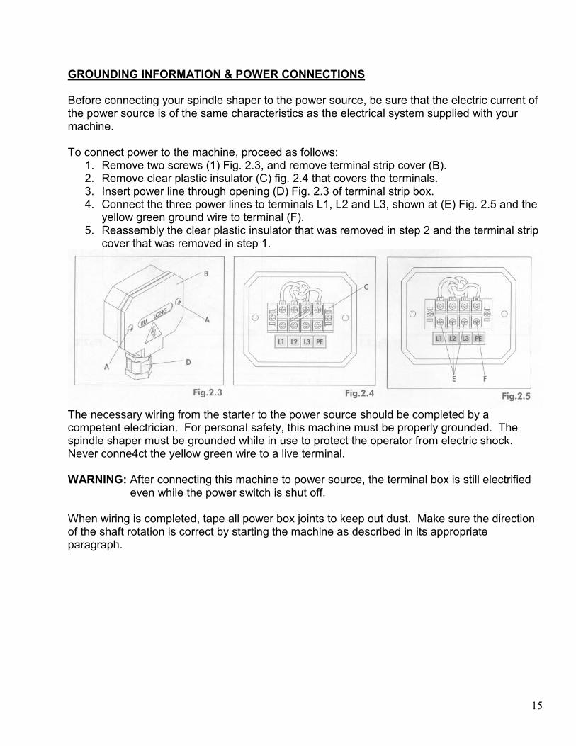
GROUNDING INFORMATION & POWER CONNECTIONS Before connecting your spindle shaper to the power source, be sure that the electric current of the power source is of the same characteristics as the electrical system supplied with your machine. To connect power to the machine, proceed as follows:
1. Remove two screws (1) Fig. 2.3, and remove terminal strip cover (B). 2. Remove clear plastic insulator (C) fig. 2.4 that covers the terminals. 3. Insert power line through opening (D) Fig. 2.3 of terminal strip box. 4. Connect the three power lines to terminals L1, L2 and L3, shown at (E) Fig. 2.5 and the
yellow green ground wire to terminal (F). 5. Reassembly the clear plastic insulator that was removed in step 2 and the terminal strip
cover that was removed in step 1.
The necessary wiring from the starter to the power source should be completed by a competent electrician. For personal safety, this machine must be properly grounded. The spindle shaper must be grounded while in use to protect the operator from electric shock. Never conne4ct the yellow green wire to a live terminal. WARNING: After connecting this machine to power source, the terminal box is still electrified
even while the power switch is shut off. When wiring is completed, tape all power box joints to keep out dust. Make sure the direction of the shaft rotation is correct by starting the machine as described in its appropriate paragraph.

16
CONTROL UNIT A control panel is provided with your spindle shaper as shown in Fig. 3.1.
A. Power Indicator (CE) B. On-Off Switch C. Forward/Reverse Switch D. Star Indicator (CE) E. Emergency Stop
ELECTRICAL CONTROLS The control unit should be used as the following to operate your machine:
1. Make certain the spindle lock is disengaged as explained in the section “Spindle Lock” and that the cabinet door is in the closed position.
2. Rotate the forward/reverse switch (C) Fig. 3.1 to either the forward rotation, or the reverse rotation. Rotate the start switch (B) to the right to start the machine. Switch (B) is a magnetic switch and as soon as the machine is started the switch will return to the center position as shown.
3. To stop the machine, push the mushroom shaped stop button (E), or turn the start/stop switch (B) to the left, or simply step on brake pedal (B) Fig 3.12, to stop the machine in seconds if this device is available.
To reverse the rotation of the spindle simply shut off the motor; then rotate the forward/reverse switch after the spindle stops completely. For CE machine, a main switch is mounted on the right side of the machine frame. Turning the switch to zero, indicates so with a sign and padlock it before servicing. The electrical cabinet door is lockable. Always close and lock this door except for service. WARNING: Never attempt to reverse the rotation of the spindle with the motor/spindle running. CAUTION: Do not use the forward/reverse switch to stop the machine or it will damage the
electrical controls. Use stop push button or brake pedal for normal stop. WARNING: Open the electrical cabinet door only while the main switch is shut off, or it may
result in electric shock.

17
SPEED CHANGE & BELT ADJUSTMENT Your machine is supplied with a 5-step motor pulley and a 5-step spindle pulley that provides spindle speeds of 3000, 4000, 6000, 8000, and 10000 RPM as standard. A large speed chart Fig. 3.3, is located on the inside of the cabinet door for easy reference of the belt position on the pulleys for the five speeds available. Check machine speed setting before operating. Make sure cutter meets or exceeds speed rating of tool. In the diagram Fig. 3.4 a concrete example of choosing a speed in function to the diameter of the utensil, and the most opportune peripheral speed for the type of material to be worked on.
Guide Values for Cutting Speed
Material Cutter HS (x s-¹) Cutter HW (m x-¹)
Softwood 50-80 60-90
Hardwood 40-60 50-80
Chipboard -- 60-80
Coreboard -- 60-80
Hard Fibreboard -- 40-60
Plastic-Coated Board -- 40-60
Example: Cutter: 160 mm diameter, vc=76m s-¹→n=9000 min-¹ The cutting speed should always exceed 40 m/s to lessen kickback risk but should never exceed 70 m/s to lessen the risk of tool damage. To change the speed and adjust the proper belt tension, proceed as follows:
1. Disconnect machine from the power source. 2. Open the door guard.
NOTE: A limit switch is provided which prevents the machine from being turned on when the
cabinet door is in the open position.

18
CAUTION: The normal stop (B) Fig. 3.1, should not be replaced by this above-mentioned
limit switch inside the door guard.
3. Move belt tension lever (A) fig. 3.5, to the right as shown, to loosen belt tension. The belt (B) can then be moved to the desired steps of the motor pulley (C) and spindle pulley (D), while at the same time, rotate knob (A) fig. 3.5.1 to slide speed bar (B) up or down so that the belt will be positioned in the cut-out in speed bar if this device is available on your machine.
4. After the belt (B) fig. 3.6, is positioned on the desired steps of the motor pulley (C) and spindle pulley (D), move tension lever (A) to the left to apply belt tension as shown.
5. Close the door guard. During the first work phase, the belt will settle and thus a reduction of the tension. Turn the two nuts (E & F) fig. 3.6, to obtain the best tension of the belt. Tension is checked by pressing the center of the belt span with a force of 3 kg; tension is correct when a 5 mm deflection is observed.

19
SPINDLE LOCK A spindle lock is provided with your machine in one of the following types to assist you when changing spindle or installing and removing cutters. CAUTION: Spindle lock can be engaged only while the machine stop completely. Basic Type 1. Open rear cover of the machine. Rotate lock knob (A) fig. 3.9, until the hole on the knob
engages the pin on the other end of the knob. The knob (A) will then be latched in “lock spindle”.
2. Close rear cover.
Standard Type A 1. To position the spindle in “loose spindle” (where the spindle will rotate freely), pull out knob
(A) fig. 3.10, and turn it clockwise. The knob (A) will then be latched in “loose spindle”. Fig. 3.10 illustrates the knob (A) pulled out in the loose spindle position.
2. To engage the spindle lock, turn knob (A) fig. 3.11, counterclockwise and push into the locked position, as shown in fig. 3.11.

20
Standard Type B 1. To position the spindle in “loose spindle” (where the spindle will rotate freely), turn knob (A)
fig. 3.10, and push into the loose position. 2. To engage the spindle lock, pull out knob (A) and turn spindle by hand till the spindle is
locked, and then turn knob. The knob will then be latched in “locked spindle”. CAUTION: Make sure spindle lock knob is in the loose position before turning “on”
the machine. Lock Pedal Simply step on lock pedal (A) fig. 3.12, on the right side to lock the spindle from running.

21
INTERCHANGEABLE SPINDLE INSTALLATION & REPLACEMENT One of the features of this machine is that it can replace the different sizes of the spindle and uses router bits. To install the spindle, proceed as follows: For Interchangeable Spindle with Draw Bar
1. Disconnect the machine from the power source and remove the table rings. 2. Turn the spindle raising and lowering hand wheel and raise the main shaft all the way to
the top. 3. The taper of the interchangeable spindle, and the internal taper of the shaft must be
cleaned thoroughly using a cloth moistened with kerosene or mineral spirits. Do not use gasoline or lacquer thinner for this purpose.
4. Thread the short threaded end of the draw bar (B) fig. 3.13, into the threaded hole in the bottom of the interchangeable spindle (A) and remove the two lock nuts and special bevel washer from the other end of the draw bar (B).
5. Very carefully insert the draw bar (B) and spindle (A) fig. 3.13, down through the shaft as shown. Make sure the tang (C), on the spindle, is engaged with the notch (D), and thread spindle nut (E) onto threads (F).
6. Engage spindle lock as explained in the section “Spindle Lock”. 7. Using the special spanner wrench (G) fig. 3.14, supplied, tighten spindle nut (E) as
shown. 8. Open the cabinet door and assemble the special bevel washer (H) to the bottom of the
draw bar (B), as shown in fig. 3.15. The bevel washer (H) was removed from the draw bar in Step 4.
9. Assemble and securely tighten the two lock nuts (I) fig. 3.15 as shown. The two lock nuts (I) were removed from the draw bar (B) in Step 4.
10. Disengage the spindle lock.
For Interchangeable Spindle Without Draw Bar
1. Disconnect machine from the power source and remove the table rings. 2. Turn the spindle raising and lowering hand wheel and raise the main shaft all the way to
the top. 3. Engage spindle lock as explained in the section “spindle lock”. 4. The taper of the spindle and the internal taper of the shaft must be cleaned thoroughly
using a cloth moistened with kerosene or mineral spirits. Do not use gasoline or lacquer thinner for this purpose.

22
5. Very carefully insert the spindle (A) fig. 3.16 to the hole of main shaft. Make sure the tang (B) on the spindle is engaged with the notch, then lock it with nut (C), and lock nut (D) in reverse direction.
6. At the upper part of the lock nut (D) tightly in order to prevent the spindle form loosening when it is used in the forward and reverse direction.
To take off spindle:
1. Before lock nut (D) is loosened, two screws (E) must be loosened first. 2. The lock nut (D) cannot be taken away alone. Only loosen the lock nut by turning
twice only, then loosen the nut (C) until the spindle is taken off.

23
SPINDLE VERTICAL TRAVEL ADJUSTMENT The spindle vertical travel adjustment can be made by means of the following methods: Type A
1. Loosen hand wheel lock (A) fig. 3.17, before making adjustment of spindle height. 2. To raise the spindle, turn hand wheel (B) counterclockwise and to lower the spindle,
turn hand wheel (B) clockwise. 3. Tighten hand wheel lock (A) when desired spindle height is obtained. 4. One complete turn of the hand wheel moves the spindle up or down by 1 or 2.5 mm
indicated on the machine frame.
Type B
1. Loosen lock lever (A) and knob (B) fig. 3.18, before making adjustment of spindle height.
2. To raise the spindle, turn hand wheel (C) counterclockwise and to lower the spindle, turn hand wheel (C) clockwise.
3. Tighten knob (B) and locking lever (A) when desired spindle height is obtained. 4. The dial indicator (D) is for the use of micro-adjustment of spindle. 5. One complete turn of the hand wheel moves the spindle up or down by 1 or 2.5 mm
indicated on the machine frame.
24
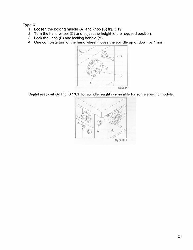
Type C 1. Loosen the locking handle (A) and knob (B) fig. 3.19. 2. Turn the hand wheel (C) and adjust the height to the required position. 3. Lock the knob (B) and locking handle (A). 4. One complete turn of the hand wheel moves the spindle up or down by 1 mm.
Digital read-out (A) Fig. 3.19.1, for spindle height is available for some specific models.

25
SPINDLE TILTING ADJUSTMENT Stop the machine before tilting the spindle. Unlock the spindle. Be sure that the cutter does not touch the table and the fences.
Forward Tilt Type The dial indicator of tilting degree indicates the figures from –5 or –10 to 45 degrees. When adjusting the tilt of spindle:
1. Replace the table rings and install the one for use with tilting spindle. 2. Loosen the knob (B) fig. 3.21 on the hand wheel (A). 3. Loosen the two locking handles © on the both sides of machine. 4. Turn the hand wheel (A) to the required tilting degree and position. 5. Tighten the knob (B) and locking handles (C).
Backward Tilt Type
The dial indicator of tilting degree indicated the figures from 10 to –45 degrees. When adjusting the tilt of spindle:
1. Replace the table rings and install the one for use with tilting spindle. 2. Loosen the knob (C) fig. 3.21.1 on the hand wheel (B). 3. Loosen the locking handle (D) on the right side of machine. 4. Turn the hand wheel (B) to the required tilting degree and position. A dial indicator
showing existing tilting degree is provided for your convenient adjustment. 5. Tighten the knob (C) and locking handle (D).

26
ASSEMBLING CUTTERS TO SPINDLE 1. Disconnect the machine from the power source and engage the spindle lock as explained
in the section “SPINDLE LOCK”. 2. Place the cutter (A) fig. 3.22 and desired spindle rings (B) on the spindle as shown. 3. Tighten nut (D) using the wrench supplied and Disengage spindle lock.
WARNING:
• Whenever possible, the cutter should be positioned on the spindle in such a way that the cut is being performed from under the surface of the work piece.
• Always place the “keyed” washer (C) fig. 3.22, on spindle before threading on nut (D). The “keyed” washer (C) prevents the nut (D), from loosening when spindle turns counterclockwise.
• After installing and replacing cutter please check one more time carefully. Be sure that the direction of cutter is correct and the keyed washer, spindle rings are directly under spindle nut and spindle nut is tightened securely.
TABLE RINGS A set of table rings is supplied with your machine and can be removed individually for use with various size cutters. A table ring for use with a tilting spindle is also available.

27
ASSEMBLING & INSTALLING FENCE & DUST HOOD Assembling Fence 1. Place fence body (A) fig. 3.23 on the table. Fasten bar (C) to the front of the fence half
using the locking lever (B) and washer. Assemble the remaining bar to the other fence half in the same manner.
NOTE: Locking levers (B) are spring-loaded and can be repositioned by pulling out the
handle and repositioning it on the nut located underneath the hub of the handle.
2. Locate the two fence locking handles (D) fig. 3.24 and washers, and fasten fence body (A) to one of the two sets of holes located on the machine table.
3. Loosen locking lever (B) fig. 3.23, and slide rear of fence half (E) fig. 3.24 onto locking bar (C) fig. 3.23. Assemble remaining fence half in the same manner. Then tighten locking lever (B).
4. Assemble top cover (F) fig. 3.24, to top of fence body using the two locking knobs (G) and washers.
Assembling Guards to Fence Body 1. Assembly spring guard (A) fig. 3.25, hold-down (B) and clear plastic guard (C) to mounting
rod (D) located on top of fence cover or fence body using rod (E) and clamps (F). 2. The spring guard (A), hold-down (B), and clear plastic guard (C) can be flipped up out of
the way when not in use or when making adjustments.

28
Fence Controls and Adjustments WARNING: The fence halves (E) fig. 3.24 should be adjusted endwise so the opening at
the spindle is never more than is required to clear the cutter. 1. To adjust the fence halves (E) fig. 3.24 endwise, loosen the two fence locking levers, slide
the fence halves to the required positions and tighten locking levers (B). 2. Each fence half (E) can be moved independently, on or out, depending on the type of
shaping operation that is being performed. To move the fence halves in or out, loosen one of the locking knobs (H) and turn one of the adjusting knob (I), depending on which fence half is being moved.
3. The complete fence assembly can be rapidly positioned on the table by loosening two locking handles (D), moving the fence assembly to the desired position and tightening the two locking handles (D).
Assembling Dust Hood Assembly dust hood (A) fig. 3.26 to rear of machine table, using the two screws and washers (B) as shown.

29
ASSEMBLING MITER GAUGE & CLAMP Assembling Miter Gauge For 5-speed Spindle Shaper with Fixed Table
1. Locate the miter gauge bar (A) fig. 3.28, and insert washer end (B) of bar into T-slot (C) of machine table.
2. Fig. 3.29 illustrates the miter gauge bar (A) in the table slot. Place the miter gauge (D) on the bar with stud (E) of bar protruding up through opening in miter gauge body as shown. Fasten in place using washer (F) and lock knob (G).
For 5-speed Spindle Shaper with Sliding Table
1. Insert post (A) fig. 3.30 of the clamp assembly down through hole (B) of the miter gauge body (C), and thread post (A) into hole (D) of sliding table.
2. Insert shaft of locking handle (E) down through opening (F) of miter gauge and thread shaft into hole (G) of sliding table.

30
Assembling Stop Rod/Fence and Stop to Miter Gauge Stop Rod for 5-speed Spindle Shaper
1. Insert stop rod (A) fig. 3.35, into hole on side of miter gauge body and lock in place with locking knobs (B).
2. Assemble stop (C) to stop rod (A) as shown, and tighten locking knob (D). Miter Gauge Clamp A clamp (E) fig. 3.35, is supplied with your miter gauge to securely hold work pieces when shaping small pieces across the grain. The clamp (E) can be moved up or down as required on post (F).
Stop Fence for Sliding Table (Optional) 1. Insert two nuts (A) fig. 3.36 of locking levers (B) into fence channel (C). 2. Position fence (E) fig. 3.37 on miter gauge with two screws (D) fig. 3.36 of locking levers
engaged into two notch (F) fig. 3.37 on top of miter gauge. 3. To slide fence (E) fig. 3.37, to the left or right, loosen locking levers (B), slide fence (E) to
the desired position and tighten locking levers (B). To tilt the fence (E), loosen locking handle (G).
4. Loosen locking levers (I) fig. 3.38, and insert nut (J) of stock stop assembly into channel on end of fence as shown.
5. Slide stock stop (K) fig. 3.39, to desired position on fence and tighten locking levers (I).

31
SLIDING TABLE ADJUSTMENT (For Sliding Table Only) There are six adjustable eccentric roller (A) fig. 3.40, on sliding table. Wherever the table is unstable or not traveling in line, adjust the sliding table as follows:
1. Use open-end wrench (B) to adjust the rollers. 2. Lock the rollers by using the hex wrench (C).
Sliding Table Lock To operate the sliding table (G) fig. 3.40, pull out and rotate knob (D) until it stays in the out position as shown. The sliding table can then be moved back and forth. To lock the sliding table, preventing it from moving, simply rotate knob (D), until knob (D) moves to the up position and the pin on the other end of the knob engages a hole underneath the table. INSTALLING TENONING HOOD (Optional) 1. Lean the hood on the table, regulate the distance from the cutters and secure the position
by tightening the locking levers (A) fig. 3.41. 2. Regulate the height of the protection in respect of the cutters by turning the knobs (B).
WARNING: The machine should be equipped with the tenoning hood when doing
tenoning work.

32
EXTENSION SUPPORT ADJUSTMENT (For extension table only) 1. Loosen the two locking knobs (A) Fig 3.43 to loosen the extension bars. 2. Pull the extension support to the desired position. 3. Tighten the two locking knobs to lock it.
SET-UP & OPERATION OF CONTROL SYSTEM FOR XT-360L Control Panel/Function of Keys Fig. 3.45 illustrates the control panel of programmable spindle shaper XT-360L
A. Power On B. Power Off C. Forward/Reverse Switch—for Spindle Rotation D. Emergency Stop E. Mai Motor Start F. Main Motor Stop
NOTE: Main motor will not start if forward/reverse switch is in neutral (“O”)
position.

33
G. Manual Operation for Spindle Height Adjustment H. Automatic Operation for Spindle Height Adjustment I. Spindle Height Adjustment Brake/Lock (Automatic Display) J. Shaft Sleeve Lock (Automatic Display) K. Spindle Height Adjustment—Up L. Spindle Height Adjustment—Down
NOTE: When manuall y depressing the “up” or “down” spindle height adjusting
keys, the shaft sleeve lock works automatically—the operator does not need to separately operate the “LOCK” and “TIGHTEN” keys.
M. Param/Now Key—used to set/check up to 10 different spindle height settings and zero reference point(s).
N. Next Key—each time next key is depressed digital readout advances to next parameter (setting).
O. Negative Signal P. Edit/Run Key—used to change “EDIT” or “RUN” mode. Flashing L.E.D. indicates
“EDIT” mode. Q. Number Keys (0-9) R. Clear Key—used to remove value and negative signal currently on digital display. S. Enter Key T. Spindle Height U. Spindle Height Position.
Power Connections Before connecting from the starter to the power source, be sure that the voltage is of the same characteristics as the electrical system supplied with your machine. “EDIT/RUN” key should be on “RUN” (with no flashing L.E.D.) Depress “UP” and/or “DOWN” key to check for proper direction. If motion is backwards change by reconnecting supply line(s) for proper direction. Enter a New Spindle Height Setting 1. “EDIT/RUN” key should be set on “EDIT” (flashing L.E.D.). 2. Key in desired spindle height setting on position “1” then depress “ENTER” key. The first
preset is now set. 3. Follow steps 1 and 2 to enter additional presets. 4. After all settings are made depress “EDIT/RUN” key till set on “RUN” mode (with no
flashing L.E.D.). From this point on each time the “ENTER” key on the control panel is depressed the spindle height setting will advance one setting.
Checking Settings Already Set-Up in System 1. “EDIT/RUN” key should be set on “RUN” (with no flashing L.E.D.). 2. Depress the “PARAM/NOW” key to view digital readout of current spindle height setting. 3. Depress the “NEXT” key to view digital readout all other settings currently in the system.
34
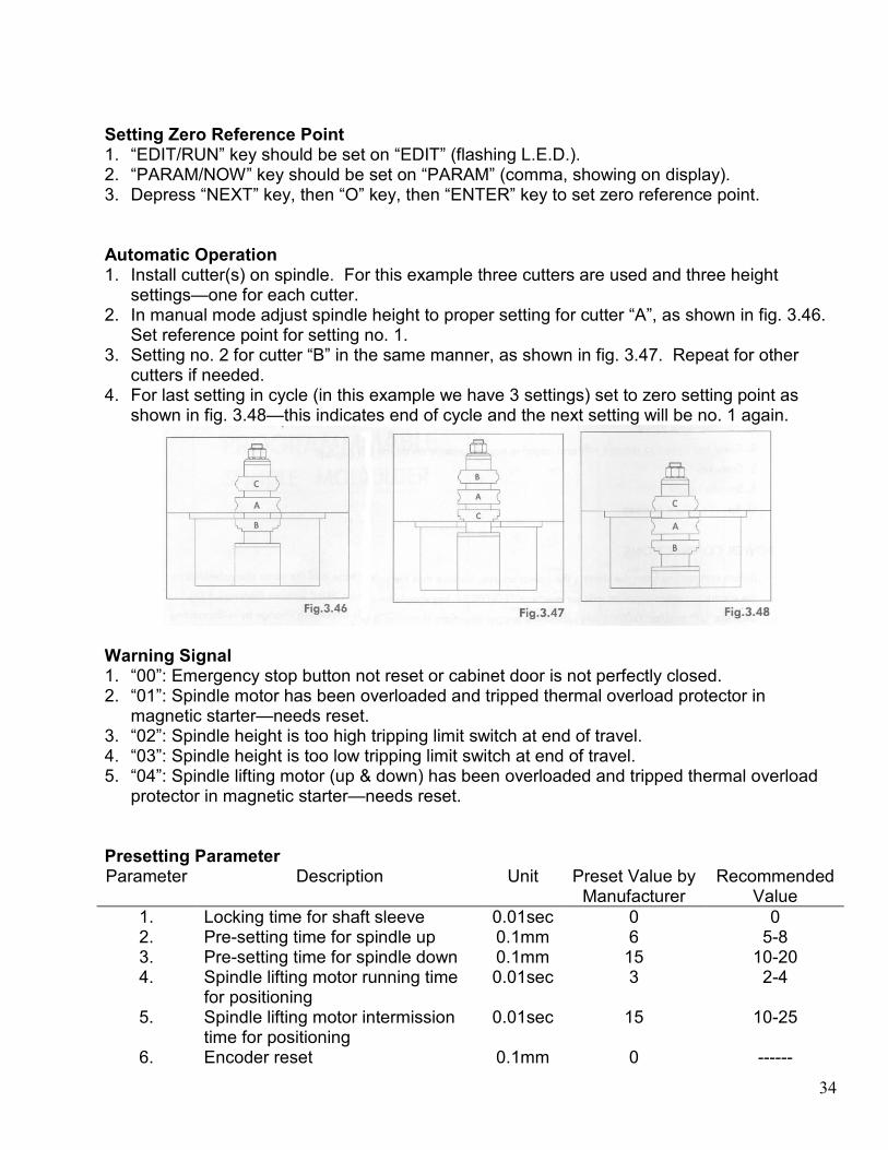
Setting Zero Reference Point 1. “EDIT/RUN” key should be set on “EDIT” (flashing L.E.D.). 2. “PARAM/NOW” key should be set on “PARAM” (comma, showing on display). 3. Depress “NEXT” key, then “O” key, then “ENTER” key to set zero reference point. Automatic Operation 1. Install cutter(s) on spindle. For this example three cutters are used and three height
settings—one for each cutter. 2. In manual mode adjust spindle height to proper setting for cutter “A”, as shown in fig. 3.46.
Set reference point for setting no. 1. 3. Setting no. 2 for cutter “B” in the same manner, as shown in fig. 3.47. Repeat for other
cutters if needed. 4. For last setting in cycle (in this example we have 3 settings) set to zero setting point as
shown in fig. 3.48—this indicates end of cycle and the next setting will be no. 1 again.
Warning Signal 1. “00”: Emergency stop button not reset or cabinet door is not perfectly closed. 2. “01”: Spindle motor has been overloaded and tripped thermal overload protector in
magnetic starter—needs reset. 3. “02”: Spindle height is too high tripping limit switch at end of travel. 4. “03”: Spindle height is too low tripping limit switch at end of travel. 5. “04”: Spindle lifting motor (up & down) has been overloaded and tripped thermal overload
protector in magnetic starter—needs reset. Presetting Parameter Parameter Description Unit Preset Value by
Manufacturer Recommended
Value
1. Locking time for shaft sleeve 0.01sec 0 0 2. Pre-setting time for spindle up 0.1mm 6 5-8 3. Pre-setting time for spindle down 0.1mm 15 10-20 4. Spindle lifting motor running time
for positioning 0.01sec 3 2-4
5. Spindle lifting motor intermission time for positioning
0.01sec 15 10-25
6. Encoder reset 0.1mm 0 ------

35
NOTE: When the actual value/position exceeds the target value/position, please adjust the parameter by increasing the value of PARAMETER 2 or reducing the value of PARAMETER 4. When the target value/position exceeds the actual value/position, please adjust the parameter by reducing the value of PARAMETER 2 or increasing the value of PARAMETER 4.
STRAIGHT WORK OPERATIONS Using the fence is the safest and most satisfactory method of shaping, and should always be used when the work permits. Almost all straight work can be done with the fence.
1. For normal work, where a portion of he original edge of the stock is not touched by the cutter, both the infeed and outfeed fences are in a straight line, as shown in fig. 4.1.
2. When the shaping operation removes the entire edge of the stock, e.g. in jointing or making a full bead, the shaped edge will not be supported by the outfeed fence then both fences are in line, as shown in fig. 4.2. In this case, the stock should be advanced to the position shown in fig. 4.2 and stopped. The outfeed fence should then be moved forward to contact the work, as shown in fig. 4.3. The outfeed fence will then be in line with the cutting circle, and the operation can continue.
WARNING: Keep guards in place and in working order. Always use fence assembly
when the work permits.

36
POSITION OF COLLARS When shaping with collars, the collar must have sufficient bearing surface, as shown in fig. 4.4. Also the work must be fairly heavy relative to the cut being made. Under no circumstances should a short, light work piece be shaped against the collars, as shown in fig. 4.5.
The collars may be used in any of the following positions;
1. When the collar is used below the cutter, as shown in fig. 4.6, the progress of the cut can be seen throughout the operation. However, any accidental lifting of the work will gouge the wood and ruin the work piece.
2. When the collar is used above the cutter, as shown in fig. 4.7, the cut cannot be seen, but this method offers an advantage in that the cut is not affected by slight variations in the thickness of the stock. Also, accidental lifting of the work piece will not gouge the work piece; simply repeat the operation to correct the mistake.
3. Using the collar between two cutters has the advantages and disadvantages of the first two procedures, and is frequently used where both edges of the work are to be molded, see fig. 4.8.
NOTE: It is advisable to place the cutter as low as possible on the spindle to reduce spindle
deflection and ensure the best possible finish. Also make sure that the contacting surfaces of the cutter are smooth, clean and without dents.

37
TENONING OPERATIONS The provided miter gauge and clamp can be used for tenoning operations. The tenoning hood fitted with adjustable sections shall be used to guard the tool from above the work piece and from the sides. WARNING: Keep guards in place and in working order. Always use tenoning hood
when processing tenoning machining. CURVED WORK Machining with Jig (Copying) When using the same procedure on multiple work pieces, a jig or template can be made to facilitate the operation:
1. Prepare the jig (A) fig. 4.9, to accommodate your original work piece. 2. Place the jig (A) against the table ring guide shoulder (B). 3. Fasten the new work piece (C) on the jig (A) with the clamp (D) and push the assembly
past the cutter.
Machining without Jig
1. Assembly the curved work guiding to machine table. 2. Place the curved work piece on table and with the shaping side in contact with the
vertical reference of the ring guide. 3. Use the starting strip as a start point to process the machining. WARNING: Keep guards in place and in working order. Always use curved work
guiding when processing curved work.

38
LUBRICATION Do not operate machine until properly lubricated.
1. Apply a drop of light machine oil occasionally on the ledge and wall of the table opening to facilitate the changing of table rings.
2. The spindle bearings should be lubricated every 200 hours of use by using the grease gun supplied (A) fig. 5.1.
3. Two grease fittings, one of which is shown at (B), are supplied on the spindle housing for this purpose. The other fitting is directly opposite fitting (B). Before lubricating, clean grease fittings (B) thoroughly and lubricate the spindle bearings with two pumps of one of the following greases:
Shell Alvania Grease R2 Dow Corning MolyKote R BR2 Esso-Becon 2 Mobile—Mobilplex 47 Texaco—Startex 2
PERIODICAL MAINTENANCE Periodically clean the inside of the machine from eventual presence of shaving or dust. Machine cleaning increases the machine life and its performance. To replace the ball bearings you should call a skilled technician. Clean the spindle with compressed air. Do not get oil on the pulleys and belts. If they are dirty, use paper or a soft rag to clean and dry them. Never place the v-belt under excessive strain, as this can overload the motor and damage the bearings, spindle or belt.

39
TROUBLESHOOTING
Trouble Possible Cause Solution
Fuse blown or circuit breaker tripped
Replace fuse or reset circuit breaker
Machine will not start
Cord damaged Have cord replaced by authorized service person
Extension cord too light or too long
Replace with adequate size cord
Feed stock too fast Feed stock more slowly
Overload kicks out frequently
Cutter is dull or has gum on it Clean or replace cutter
Extension cord too light or too long
Replace with adequate size cord
Low current Contact local electric company
Motor not wired for correct voltage
Refer to motor nameplate for correct wiring
Tool does not come up to speed
Spindle is locked Release spindle lock knob
Dull cutter Replace cutter
Gum or pitch on cutter Remove cutter and clean with turpentine and steel wool
Gum or pitch on table causing erratic feed
Clean table with turpentine and steel wool
Machine makes unsatisfactory cuts
Feeding work in wrong direction
Feed work against cutter rotation
Dull cutter Sharpen by honing on flat side
Cutter too deep On hardwoods take light cuts; attain full depth of cut with several passes
Stock burns
Forcing work Feed slowly and steadily
Damaged tool Replace tool
Stand or bench on uneven floor
Reposition on flat, level surface
Bad v-belt Replace belt
V-belt not tensioned correctly Adjust belt tension by moving motor bracket
Bent pulley Replace pulley
Machine vibrates excessively
Improper motor mounting Check and adjust motor mounting
Make cross-grain cuts first then finish with grain
Edge splits off on cross-grain cut
Characteristic of cut
Use scrap block to support at end of cut

40
Keep work firmly against fence or collars throughout pass
Raised areas on shaped edge Variation in pressure which holds work against cutter
Use hold-downs
Use miter gauge with hold-down to start cut when shaping freehand; hold work firmly against fence
Work pulled from hand of cut No support
Adjust the tension of spring plate
Misalignment Adjust outfeed fence Depth of cut not uniform
Side pressure not uniform Use hold-downs; keep pressure against fence or collars consistent
Keep pressure firm throughout pass
Use hold-downs
Make pass slowly and steadily
Variation in height of cut Variation in pressure which holds work down on table
Whenever possible, keep cutter under stock
Wrong RPM Use faster speed
Feeding too fast Pass stock more slowly
Working against grain Work with grain whenever possible
Cuts not smooth
Cutting too deep On very deep cuts make several passes
Spindle does not raise freely Sawdust and dirt in raising mechanisms
Brush or blow out loose dust and dirt

41
PARTS LIST FA-03-3D

42
FA-03-3D
No Description Qty Part No
1 Guide 1 5112410
2 M6x10 Hex Soc Head Screw 2
3 M8 Spring Washer 3
4 Cap RH 1 5122280
5 Guide 2 5122210
6 Fence RH 1 5122224
7 Fence LH 1 5122223
8 Cap LH 1 5122281
9 Guide 1 5112420
10 Bar Horz 1 FA31120
11 Block 4 FA31010
12 Bar Vert 1 FA31100
13 Bar Vert 1 FA31110A
14 Knob w/ Stud 7
15 Clip 8 FA31040
16 Warning Label 1
17 Shield 1 5112400
18 M6 Spring Washer 1
19 M6x20 Cheese HD Screw 1
20 Bar Horz 1 FA31090
21 M8 Hex Nut 1
22 Block 1 FA31020
23 Bar Horz 1 FA31080
24 Bar Vert 1 FA31070
25 M8 Hex Nut 1
26 M8x35 Hex Soc Set Screw 1
27 M5 Spring Washer 2
28 M5 Lock Nut 2
29 Latch 1 FA31050
30 M5x10 Hex Soc Head Screw 2
31 Cam Washer 2 5112430
32 M5x10 Hex Soc Head Screw 2
33 Bracket 1 FA31030
34 M6x20 Hex Soc Head Screw 4
35 Plate 1 5122150
36 Lock Handle 1 FA31140
37 M14 Washer 1
38 Fence Body 1 FA31060
39 M10x35 Lock Lever 1
40 M8 Flat Washer 1
41 M6x30 Hex Soc Head Screw 2
42 Block 1 FA31130
43 Ram 1 FA22080

43
44 Adjusting Screw 1 FA22090
45 Housing 1 FA22100
46 M8x8 Hex Soc Set Screw 2
47 Bushing 1 FA22120
48 Dial Indicator 1
49 Knob w/ Stud 1 FA22110
50 M8x8 Hex Soc Set Screw 1
51 M6x20 Hex Soc Head Screw 2
52 Guide 1 FA22400
53 M6x25 Hex Soc Head Screw 2
54 Cover 1 FA22230
55 Nut 1 FA22140
56 M4x10 Hex Soc Flat Head Screw 4
57 Cover 1 FA22210
58 Worm Shaft 1 FA22200
59 Bolt 2
60 Retaining Ring 1
61 Bearing 1
62 M8x8 Hex Soc Set Screw 1
63 Worm Shaft 1 FA22180
64 M8x8 Hex Soc Set Screw 1
65 Retainer 1 FA22170
66 M8x16 Hex Soc Set Screw 1
67 Busing 1 55F1100
68 Lock Knob 1
69 M8x8 Hex Soc Head Screw 1
70 M10x30 Hex Soc Head Screw 3
71 Worm Base 1 FA22220
72 Gear 1 FA22270
73 M8x16 Hex Soc Set Screw 1
74 Bushing 1 FA22250
75 M8 Flat Washer 2
76 Knob w/ Stud 2
77 M5.4 Hex Soc Set Screw 1
78 Bushing 1 FA22260
79 M5x12 Cheese Head Screw 4
80 M5 Flat Washer 4
81 Bolt 1 FA22410
82 Handle 1 FA22300
83 Hand Wheel 1 FA22290
84 Dust Collector 1
85 M6x6 Hex Soc Set Screw 1
86 M6x6 Hex Soc Set Screw 1
87 Dial Indicator 1
88 M5x12 Hex Soc Head Screw 2

44
SS-520-101A

45
SS-520-101A
No Description Qty Part No
101 Spindle Nut 1 5111521
102 Keyed Washer 1 5111570
40mm Spacer Set 1 5117156 103
50mm Spacer Set 1 11C2050B
104 M5x10 hex Soc Head Screw 2
105 Retaining Nut 1 5131100
106 Retaining Nut 1 5131090
107 Bushing 1 5131080
6mm Retaining Ring 1 5131730
8mm Retaining Ring 1 5131731
9mm Retaining Ring 1 5131732
108
12mm Retaining Ring 1 5131733
109 Collet Chuck 1 5131070
110 Interchangeable Spindle 1 5131065
111 M5x16 Hex Soc Head Screw 4
112 Plate 1 5151520
113 Bearing 2
114 6x54 Key 1
115 Retaining Ring 1
Spindle (7.5 HP) 1 5151511 116
Spindle (10 HP) 1 55F6010
117 Disk Spring 2
118 Bearing 1
Retainer Nut (7.5 HP) 1 5151270 119
Retainer Nut (10 HP) 1 55F6030
Spindle Pulley (7.5 HP) 1 5111160 120
Spindle Pulley (10 HP) 1 5131140A
Nut (7.5 HP) 1 5111170 121
Nut (10 HP) 1 5131151
122 M6x6 Hex Soc Set Screw 1
123 Belt 1
Spindle (7.5 HP) 1 55F6021 124
Spindle (10 HP) 1 5151444
125 Bearing 2
126 Spacer 1 13C3010A
40mm Ring Washer 1 5111120 127
50mm Ring Washer 1 5111530

46
SS-520T-212

47
SS-520T-212
No Description Qty Part No
201 Insert Ring 1 5157110A
202 Insert Ring 1 5157120A
203 Insert Ring 1 5157130A
204 Insert Ring 1 5157140A
205 Insert Ring 1 5157150A
206 Insert Ring 1 5203180
207 M5x10 Cheese Head Screw 4
208 M5 Washer 4
209 Dust Collector 1 5201070A
210 Table 1 5203200
211 M6x12 Cheese Head Screw 4
212 Cover 1 5203040
213 M12 Washer 4
214 M12 Washer 4
215 M12x45 Hex Soc Screw 4
216 Cabinet 1 5203060
217 Cover 1 5203160
218 Cover 1 5203260
219 Panel 1 5204010
220 M4x10 Cheese Head Screw 8
221 Cover 1 5203220A
222 Block 1 12C1050
223 M6 Hex Nut 1
224 M6x55 Cheese Head Screw 1
225 M5x10 Hex Soc Head Screw 2
226 Bracket 1 12C1061
227 Handle 1
228 Latch 1
229 Knob 1 55F1111A
230 Spring 1 55F1112
231 Fixed Screw 1 55F1113A
232 M10 Hex Nut 1
233 M10 Hex Nut 1
234 M12 Cup Nut 1
235 M12 Washer 1
236 Hand Wheel 1 5203050A
237 Knob w/ Stud 1
238 M5x16 Cheese Head Screw 2
239 Terminal Base 1
240 M4x10 Cheese Head Screw 2
241 Seal 1
242 Cover 1
243 M6x16 Cheese Head Screw 2

48
244 M5x12 Cheese Head Screw 2
245 Indicator Scale Base 1 5203070
246 Label 1
247 Control Box 1 55F3010A
248 M6x22 Cheese Head Screw 4
249 Pin 1
250 Bracket 1 5112320
251 M6x12 Hex Soc Set Screw 1
252 Pad 1 5112350
253 Lever 1 5112360
254 Plunger 1 5112330
255 Spring 1 5112340
256 M8x12 Hex Soc Set Screw 1
257 Rod Horz 1 5112310
258 Rod Vert 1 5112291
259 Block 1 5112300
260 M10 Lock Washer 2
261 M10x35 Hex Soc Screw 2
262 Knob 1 5112280A
263 Stud 1 5112260
264 M10 Washer 1
265 Body 1 5112270A
266 M8x12 Hex Soc Set Screw 1
267 Pivot Stud 1
268 Guide Bar 1 5112240
269 Knob w/ Stud 2
270 M4x10 Hex Soc Flat Head Screw 1
271 Retainer Nut 1 5112250
272 Rod 1 5112370
273 Knob w/ Stud 1 5112540
274 Stop Block 1 5112380A
49
SS-520S-311

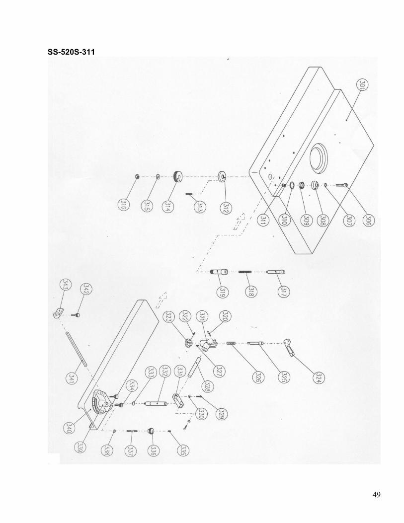
50
SS-520S-311
No Description Qty Part No
301 Table 1 5203010
302 Spacer Ring 8 5114210
303 M5x45 Cheese Head Screw 8
304 M5 washer 8
305 Cover 2 55F3050
306 M8x50 Hex Soc Head Screw 6
307 Ring Nut 6 5114100
308 Bearing Race 6 5114110
309 Ball Bearing 6
310 Retaining Ring 6
311 Bushing 6 5114140
312 Nut 1 5114060
313 M5x30 Hex Soc Set Screw 1
314 Ring 1 5114080
315 M10 Lock Washer 1
316 M10 Hex Nut 1
317 Pin 1 5134030
318 Spring 1
319 Housing 1 5134050
320 Roll Pin 1
321 Bracket 1 5112320
322 M6x12 Hex Soc Set Screw 1
323 Pad 1 5112350
324 Lever 1 5112360
325 Plunger 1 5112330
326 Spring 1 5112340
327 M8x12 Hex Soc Set Screw 1
328 Rod Horz 1 5112310
329 M10x35 Hex Head Screw 2
330 M10 Lock Washer 2
331 Block 1 5112300
332 Rod Vert 1 5112290
333 Ext Ret Ring 1
334 Knob w/ Stud 2
335 M8x10 Hex Soc Set Screw 1
336 Knob 1 5112280A
337 Stud 1 5112260
338 M10 Flat Washer 1
339 Body 1 5112271A
340 Sliding Table 1 5127010
341 Rod 1 5112370
342 Knob w/ Stud 1 5112540
343 Stop Block 1 5112380A
51
SS-520T-501

52
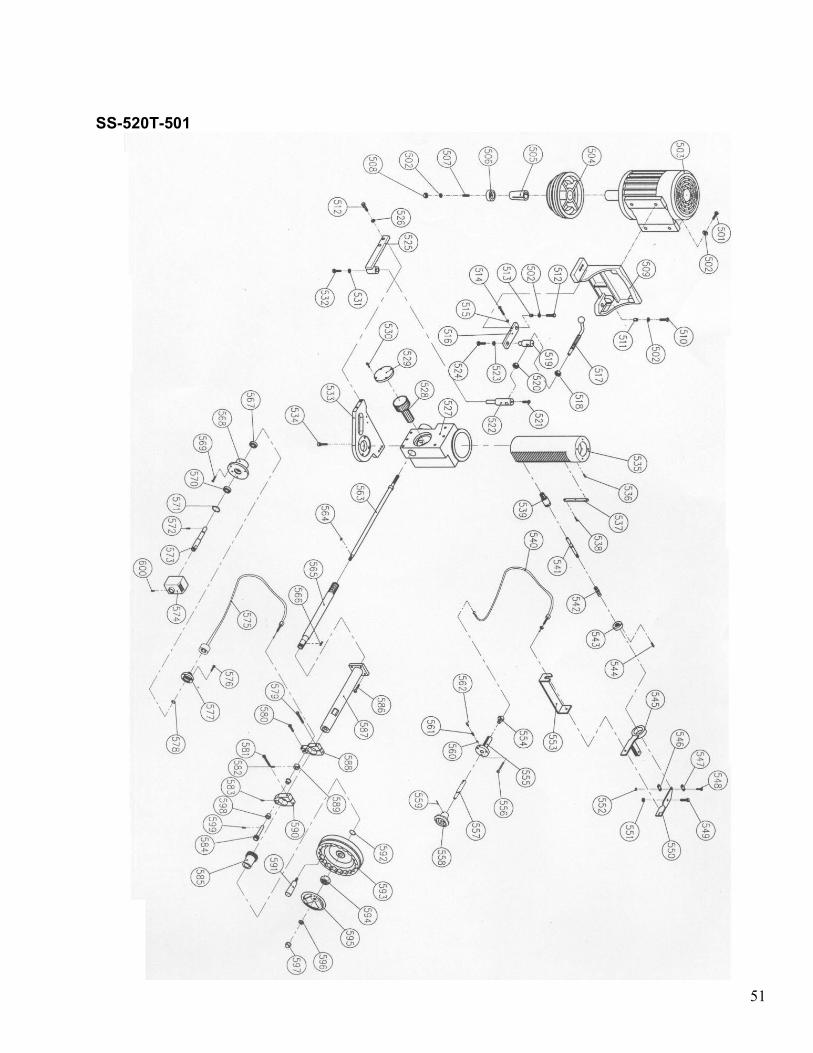
SS-520T-501
No Description Qty Part No
501 M10x35 Hex Soc Head Screw 4
502 M10 Spring Washer 7
503 Motor 1
50 HZ Motor Pulley (7.5 HP) 1 5111230 504
50 HZ Motor Pulley (10 HP) 1 5131213
Bushing 1 5121220 505
Bushing 1 5131200
Retainer 1 5111550 506
Retainer 1 5131201
507 M10x35 Hex Soc Set Screw 1
508 M10 Nut 1
509 Motor Plate 1 5133380
510 M10x50 Hex Soc Head Screw 1
511 Spacer 1 5111480
512 M10x30 Hex Soc Head Screw 1
513 Spacer 1 5111470
514 M8x16 Cheese Head Screw 1
515 M8 Hex Nut 1
516 Link 1 5121430
517 Handle 1 5111460
518 M16 Hex Nut 1
519 Stud 1 5111440
520 M16 Hex Nut 1
521 M8x30 Hex Soc Head Screw 1
522 Stud 1 5131680
523 M8 Washer 1
524 M8x30 Hex Soc Head Screw 1
525 Link 1 5133210
526 M10 Washer 1
527 Sleeve 1 5203030
528 Gear 1 5111250A
529 Cover 1 5111260
530 M5x20 Hex Soc Head Screw 4
531 M8 Washer 1
532 M8x16 Hex Soc Head Screw 1
533 Support 1 5203171A
534 M10x40 Hex Soc Head Screw 4
535 Shaft 1 5203210
536 Grease Fitting 1
537 Key 1 5203150
538 M6x20 Hex Soc Head Screw 2
539 Bushing 1 5121330
540 Cable Assembly 1 55F3060

53
541 Shaft 1 5121340
542 Spring 1
543 Nut 1 5111360
544 Nut 1
545 Support 1
546 Joint Block 1 5123200
547 Joint Block 1 5123191
548 M4x20 Hex Soc Head Screw 1
549 M8x20 Hex Soc Head Screw 1
550 Link 1 5123171
551 M8 Hex Nut 1
552 M4 Washer 1
553 Support 1 5203290
554 Housing 1 11C3030
555 Housing 1 11C3040A
556 M5x16 Hex Soc Set Screw 1
557 Plunger 1 511-1045
558 Knob 1 511-1047
559 M8x12 Hex Soc Set Screw 1
560 8mm Steel Ball 1
561 Spring 1
562 M10x10 Hex Soc Set Screw 1
563 Shaft 1 5203230
564 4x12 Key 1
565 Worm Shaft 1 5203240
566 4x24 Key 1
567 Bearing 1
568 Housing 1 5201040
569 M5x16 Cheese Head Screw 3
570 Bearing 1
571 Retaining Ring 1
572 M5x16 Hex Soc Set Screw 1
573 Shaft 1 5201030
574 Dial Indicator 1
575 Cable Assembly 1
576 M5x16 Hex Soc Head Screw 4
577 Cover 1 5203190A
578 Retaining Ring 1
579 M8x50 Hex Soc Screw 1
580 M8x40 Hex Soc Screw 1
581 M8x50 Hex Soc Screw 1
582 M6x30 Hex Soc Set Screw 1
583 M5x12 Hex Soc Set Screw 2
584 Gear 1 5203090A
585 Gear 1 5203080
586 M6x25 Hex Soc Head Screw 4

54
587 Housing 1 5203130
588 Housing 1 5203120A
589 Spacer 1 5203100
590 Housing 1 5203110
591 Handle 1
592 Retaining Ring 1
593 11” Hand Wheel (mm) 1 5203350
594 Hex Nut 1
595 5” Handle Wheel 1 5111320
596 M12 Washer 1
597 M12 Cap Nut 1
598 Bushing 2 5203310

55
SS-520T-601

56
SS—520T-601
No Description Qty Part No
601 Lock Lever 1 513-4009
602 Bushing 1 513-4005
603 Guide 1 513-4001
604 Slide LH 1 513-4003
605 Slide Body 1 513-4004
606 M12x50 Hex Soc Screw 5
607 M6x20 Hex Soc Head Screw 6
608 M10x25 Hex Soc Head Screw 6
609 Plate 1 5203020
610 M5x20 Hex Soc Head Screw 4
611 Cover 1 5111260
612 Gear 1 5111250A
613 Sleeve 1 5203030
614 M6x16 Hex Soc Head Screw 1
615 Special Nut 1 513-4007
616 Guide 1 513-4001
617 Bushing 1 513-4006
618 Lock Lever 1 513-4008
619 M8x35 Hex Soc Head Screw 3
620 M8 Washer 3
621 Gear 1 5203270
622 Slide RH 1 513-4002
623 M5x16 Hex Soc Set Screw 1
624 Chain 1
625 Gear 1 5201050
626 Retaining Ring 1
627 Bearing 1
629 M5x16 Cheese Head Screw 3
630 Bearing 1
631 Retaining Ring 1
632 Shaft 1 5201030
633 Dial indicator 1
634 M6x25 Hex Soc Head Screw 4
635 Housing 1 5203340
636 6204Z Bearing 1
637 Gear 1 5203140
638 M5x30 Hex Soc Set Screw 1
639 Gear Shaft 1 5203300A
640 6204Z Bearing 1
641 Housing 1 5203330
642 M6x25 Hex Soc Head Screw 4
643 Housing 1 5203370
644 Housing 1 5203380
645 M8x30 Hex Soc Set Screw 2