Manual V8 ver.2 - Vivid Racing V8 ver.2.pdf · 1 MANUAL INSTALLATION OF KLEEMANN Comfort Power...
28
1 MANUAL INSTALLATION OF KLEEMANN Comfort Power COMPRESSOR KIT V8 MERCEDES-BENZ ENGINE 113 Introduction These fitting instructions constitute a helping hand for the installation of the KLEEMANN Compressor System. It is recommended to read the instructions before installing the kit, so that you can gain an overview of the entire installation before you begin. If questions arise during the installation, you are welcome to contact us. KLEEMANN A/S will be ready to answer questions and provide assistance. Please do not hesitate to call us with any inquiries. It is essential to all of us that the final installation results in a properly tuned car and a satisfied customer. Yours faithfully Soren Jess President, KLEEMANN A/S Kleemann Guarantee After installing the KLEEMANN Compressor System please fill in the warranty form. Send or fax a copy to KLEEMANN, keep a copy for yourself and give the original to the customer. For the Kleemann warranty to be effective the form must be returned to KLEEMANN after the 1500 km service. Professional and qualified persons should only carry out the installation. The responsibility for correct installation rests solely with the mechanic installer, and KLEEMANN A/S is not responsible for injuries that may be inflicted upon equipment or persons due to insufficient installation. The installation instructions and the belonging instructions are only intended as a guide and cannot be regarded as exhaustive. The information in these instructions has been carefully revised and is considered correct. However KLEEMANN A/S assumes no responsibility for the contents in case of inaccuracies, and KLEEMANN A/S cannot under any circumstances be made responsible for any loss or damage occurring as a direct or indirect consequence of the application of the material. KLEEMANN A/S is not under obligation to update the material or inform the purchasers about any updates. Copyright law protects this material. Any copying modification or change is not allowed. The material may only be used to the extent agreed with KLEEMANN A/S.
Transcript of Manual V8 ver.2 - Vivid Racing V8 ver.2.pdf · 1 MANUAL INSTALLATION OF KLEEMANN Comfort Power...
1
MANUAL INSTALLATION OF
KLEEMANN Comfort Power COMPRESSOR KIT V8 MERCEDES-BENZ ENGINE 113
Introduction
These fitting instructions constitute a helping hand for the installation of the KLEEMANN Compressor System. It is recommended to read the instructions before installing the kit, so that you can gain an overview of the entire installation before you begin. If questions arise during the installation, you are welcome to contact us. KLEEMANN A/S will be ready
to answer questions and provide assistance. Please do not hesitate to call us with any inquiries. It is essential to all of us that the final installation results in a properly tuned car and a satisfied customer.
Yours faithfully Soren Jess
President, KLEEMANN A/S
Kleemann Guarantee
After installing the KLEEMANN Compressor System please fill in the warranty form. Send or fax a copy to KLEEMANN, keep a copy for yourself and
give the original to the customer. For the Kleemann warranty to be effective the form must be returned to KLEEMANN after the 1500 km service.
Professional and qualified persons should only carry out the installation. The responsibility for correct installation rests solely with the mechanic installer, and KLEEMANN A/S is not responsible for injuries that may be inflicted upon equipment or persons due to insufficient installation. The installation instructions and the belonging instructions are only intended as a guide and cannot be regarded as exhaustive. The information in these instructions has been carefully revised and is considered correct. However KLEEMANN A/S assumes no responsibility for the contents in case of inaccuracies, and KLEEMANN A/S cannot under any circumstances be made responsible for any loss or damage occurring as a direct or indirect consequence of the application of the material. KLEEMANN A/S is not under obligation to update the material or inform the purchasers about any updates. Copyright law protects this material. Any copying modification or change is not allowed. The material may only be used to the extent agreed with KLEEMANN A/S.
2
KLEEMANN A/S Rugmarken 27 B
3520 Farum Denmark
Tel. +45 70 109 109 - Fax +45 70 109 108
www.Kleemann.dk
Last update September 2007 This manual depicts the installation on an S Class (W 220) ME 2.8
Edited by Morten Piil Gøttrup
IMPORTANT while the car is still stock, use star diagnosis tester to make sure that there are no current faults regarding the engine function.
Before the installation of the KLEEMANN Compressor System the engine and engine bay should be thoroughly cleaned.

3
Dismount :
The plastic cover over the engine.
The intake pipe between the throttle body and air filter box, including the airflow meter.
The clip holding the water hose near the oil filter.
The wiring harness connections to: EGR valve Ignition coils, injectors Throttle body The manifold adjustment valve.
All vacuum connections to the intake manifold, throttle body, brake booster, and fuel line.
The intake manifold.
The knock sensor wires (disconnect the plug and run it under the water hose at the left rear cylinder head, and reconnect).
The accessory belt. Remove the idler pulley that sits at the highest point of the engine. The long bolt holding this idler pulley will be used again.
Install new spark plugs – Use only Kleemann certified spark plugs
Empty the cooling system
4
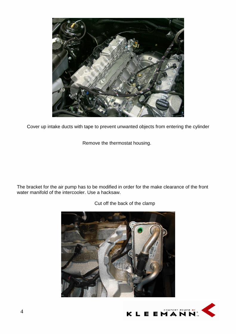
Cover up intake ducts with tape to prevent unwanted objects from entering the cylinder
Remove the thermostat housing.
The bracket for the air pump has to be modified in order for the make clearance of the front water manifold of the intercooler. Use a hacksaw.
Cut off the back of the clamp

5
Cut the bracket down the middle as shown
Remove the thermostat with a pair of needle nose pliers. It is important to remove the thermostat as shown in the picture or permanent damage to the thermostat will be the result!
.
Install the thermostat in the KLEEMANN thermostat housing.
On the SLK you have to use the O.E thermostat housing and rotate it so it clears the SC and fit bigger washers to the screws. Note that the screws do not fit the holes anymore but are lined up against the edge of the holes which is why we recommend bigger washers.

6
A M8 tread has to be made in the O.E. water pump to fit the Kleemann bracket, use the long M 8 torx bolt from the O.E. pulley wheel in the other side.
Fit the Kleemann support pulley wheel to the bracket and fit the belt

7
Mill down the tap, so that temp. sensor can be turned horizontally.
Cut off the breather hose as shown, and install it onto the throttle body.

8
Remove the EGR pipe from the factory manifold. Cut off the of the EGR pipe that fits inside the manifold. Make sure that the pipe is cut flush with the flange. Install the EGR pipe on the
KLEEMANN manifold. Use the original screws and gasket. Apply sealant.
Remove the throttle body from the original manifold. Clean the throttle body valve/housing thoroughly using brake cleaner etc. and install it onto the KLEEMANN manifold. Install spacer between throttle unit and inlet. Connect the breather hose to the TB before mounting the TB on the Compressor. Use the original screws and new gasket/sealing. When installing on compressor apply a small bed of sealant between spacer and compressor.
9
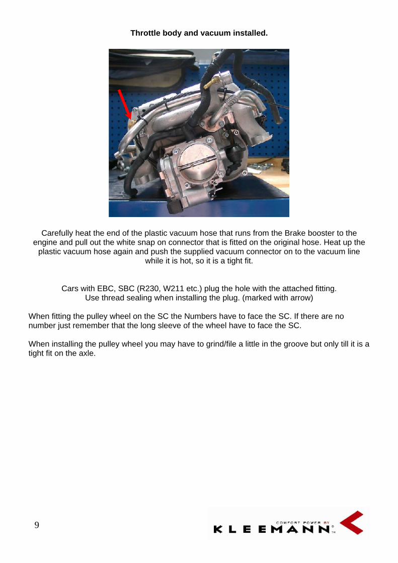
Throttle body and vacuum installed.
Carefully heat the end of the plastic vacuum hose that runs from the Brake booster to the engine and pull out the white snap on connector that is fitted on the original hose. Heat up the
plastic vacuum hose again and push the supplied vacuum connector on to the vacuum line while it is hot, so it is a tight fit.
Cars with EBC, SBC (R230, W211 etc.) plug the hole with the attached fitting. Use thread sealing when installing the plug. (marked with arrow)
When fitting the pulley wheel on the SC the Numbers have to face the SC. If there are no number just remember that the long sleeve of the wheel have to face the SC.
When installing the pulley wheel you may have to grind/file a little in the groove but only till it is a tight fit on the axle.

10
Tank ventilation
Connect the supplied hose to the 8mm pipe on the inlet housing using the supplied cobra
clamps, in order to connect the tank ventilation. Next to the 8 mm tap there is two 4 mm taps. Mount the vacuum line so that it is long enough to reach the front of the compressor.
Remove the original fuel injector rail and
dismount all of the injectors from the rail:
Cut off the locating tab on the inlet
end of the fuel injectors so that it’s
possible to reinstall each injector and
rotate it 360 degrees. (note. Arrow)
Lubricate both o-rings on all injectors
so they are not cut or pinched. ( USE
Silicone grease)
Install the fuel injectors in the
KLEEMANN fuel injector rail.
Install the KLEEMANN fuel rail with
the injectors onto the KLEEMANN
manifold.
Apply sealant to the four fuel injector rail screws and
install them into the KLEEMANN manifold. The fuel rail
mounting holes are tapped through the manifold and
using sealant ensures that there are no vacuum/ pressure
leaks.

11
locating tab is cut off.
Turn the KLEEMANN manifold upside down. To check for leaks: Spray a small amount of brake cleaner into the injector seat holes. Use an air gun (as shown) to apply air pressure to the upper
side of the seat to se any leaks between the O-ring and the seat. Make sure that the injectors are sealed fully against the fuel rail and that the injector clip is locked
12
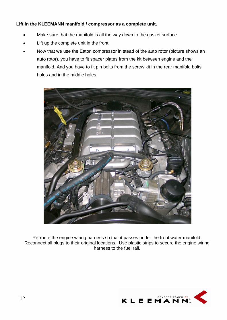
Lift in the KLEEMANN manifold / compressor as a complete unit.
Make sure that the manifold is all the way down to the gasket surface
Lift up the complete unit in the front
Now that we use the Eaton compressor in stead of the auto rotor (picture shows an
auto rotor), you have to fit spacer plates from the kit between engine and the
manifold. And you have to fit pin bolts from the screw kit in the rear manifold bolts
holes and in the middle holes.
Re-route the engine wiring harness so that it passes under the front water manifold. Reconnect all plugs to their original locations. Use plastic strips to secure the engine wiring
harness to the fuel rail.
13
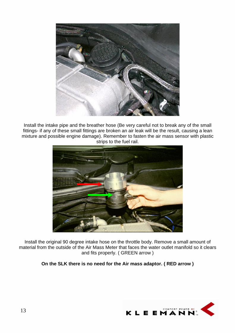
Install the intake pipe and the breather hose (Be very careful not to break any of the small fittings- if any of these small fittings are broken an air leak will be the result, causing a lean
mixture and possible engine damage). Remember to fasten the air mass sensor with plastic strips to the fuel rail.
Install the original 90 degree intake hose on the throttle body. Remove a small amount of material from the outside of the Air Mass Meter that faces the water outlet manifold so it clears
and fits properly. ( GREEN arrow )
On the SLK there is no need for the Air mass adaptor. ( RED arrow )

14
Remove the 4 rubber mounts from the valve covers.
Install the rubber mounts onto the KLEEMANN extension arms and mount on the valve cover again.
When installing compressor on SLK the extensions arms are not needed.
Install the magnetic valve from the original manifold. Loop the air hose as shown on the picture and connect to the O.E wiring harness.

15
Cut the coolant line from the expansion tank. Install the plastic T-piece connection. Connect the supplied hose between the third leg of the connector and the outlet water manifold stub on the
back of the SC. ( One Way Valve has to be fitted also so do not connect to the stub yet.)
Mount the One Way Valve between the hose coming from the third leg of the T-piece and the SC. Important; the arrows on the valve ( red arrow ) MUST be pointing towards the SC outlet.
( One Way Valve must be assembled using Thread sealing )

16
Air pump and vacuum lines
Take the vacuum lines from the SC and mount one on the MAP sensor ( GREEN arrow ) in the front of the engine and one on the air pump valve ( RED arrow ). Mount the O.E vacuum lines
between the vacuum dash pots ( BLUE arrows ) and the Air pump valve. Use the supplied KLEEMANN hose to attach the air pump to the dash pots hose. Extend the positive lead to
reach the auxiliary air pump, ground to the chassis. Due to a wide variety of equipment available on different vehicles a definitive location cannot be suggested.

17
Remove the front bumper. You may have to remove some of the radiator covers for access to install the KLEEMANN radiator. Install the KLEEMANN radiator as shown in the picture. On
some models the O.E radiator has to be lifted in order to install the intercooler. On other models the intercooler can be bolted directly on to the front bridge.
Electric water pump installation
The water pump is mounted in the lower right front side of the engine bay, just behind the fog light. On some cars a different location maybe preferred due to the wide variety of equipment on
MB cars. Place the pump on the side member, using the water pump bracket and the rubber damper. On the side member there are pre-fabricated holes on all cars that fit the bracket. This location is universal on all V8 cars except on the ML, where it’s placed inside the engine bay, on
the other side of the side member.
18
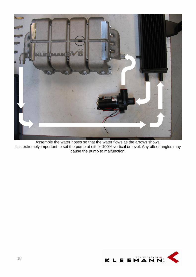
Assemble the water hoses so that the water flows as the arrows shows. It is extremely important to set the pump at either 100% vertical or level. Any offset angles may
cause the pump to malfunction.

19
To prolong the life expectancy of the pump, do a loop that faces down, on the wires from the pump, so if the water should run along the lines it will drip instead of going in to the pump and
cause malfunction.
A wire is drawn form the pump+ to the relay box where it is joined in the kit relay as shown.
20
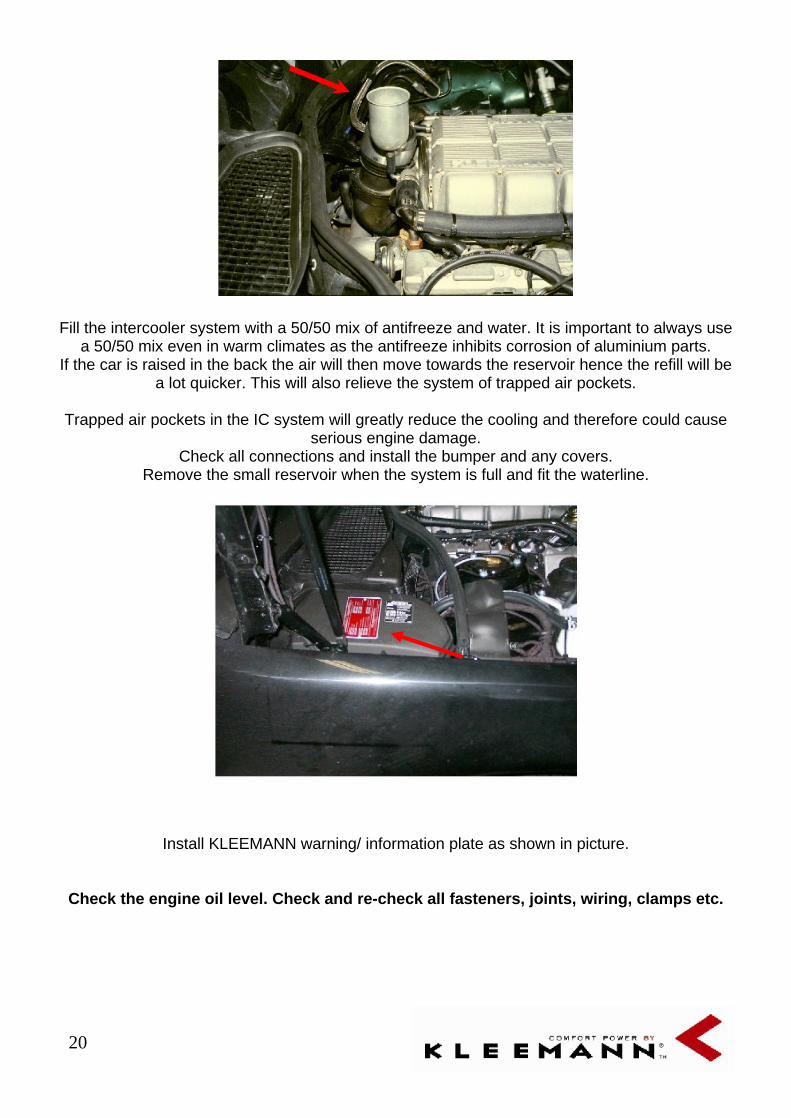
Fill the intercooler system with a 50/50 mix of antifreeze and water. It is important to always use a 50/50 mix even in warm climates as the antifreeze inhibits corrosion of aluminium parts.
If the car is raised in the back the air will then move towards the reservoir hence the refill will be a lot quicker. This will also relieve the system of trapped air pockets.
Trapped air pockets in the IC system will greatly reduce the cooling and therefore could cause serious engine damage.
Check all connections and install the bumper and any covers. Remove the small reservoir when the system is full and fit the waterline.
Install KLEEMANN warning/ information plate as shown in picture.
Check the engine oil level. Check and re-check all fasteners, joints, wiring, clamps etc.
21
Kleemann Air Mass resistor
(Air mass resistor is only needed on 5 speed gearbox or without EMS.) Locate the yellow/white air mass lead and cut the wire. Then install the Kleemann resistor between the wires. Doesn’t matter which lead goes where. When measuring, the voltage must not exceed 4,85 volts when driving full throttle all the way to the gearshift. Exceeding 4,85 volts could result in engine damage. Always measure on the wire going towards the ECU (after Kleemann resistor).( Only 5 speed gearbox or without EMS.)
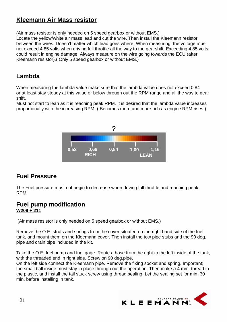
Lambda
When measuring the lambda value make sure that the lambda value does not exceed 0,84 or at least stay steady at this value or below through out the RPM range and all the way to gear shift. Must not start to lean as it is reaching peak RPM. It is desired that the lambda value increases proportionally with the increasing RPM. ( Becomes more and more rich as engine RPM rises )
?
Fuel Pressure
The Fuel pressure must not begin to decrease when driving full throttle and reaching peak RPM.
Fuel pump modification
W209 + 211
(Air mass resistor is only needed on 5 speed gearbox or without EMS.)
Remove the O.E. struts and springs from the cover situated on the right hand side of the fuel tank, and mount them on the Kleemann cover. Then install the tow pipe stubs and the 90 deg. pipe and drain pipe included in the kit.
Take the O.E. fuel pump and fuel gage. Route a hose from the right to the left inside of the tank, with the threaded end in right side. Screw on 90 deg.pipe. On the left side connect the Kleemann pipe. Remove the fixing socket and spring. Important; the small ball inside must stay in place through out the operation. Then make a 4 mm. thread in the plastic, and install the tail stuck screw using thread sealing. Let the sealing set for min. 30 min. before installing in tank.
0,84
1,16
1,00
0,68
0,52
LEAN
RICH

22
Kleemann fuel regulator
1. Fuel inlet 2. Fuel out
Sever the fuel line between the fuel filter and the fuel tank and inset the fuel regulator. The pipe on the filter marked as “Tank” is used for the tank return.
On the back of the regulator you will find the vacuum/pressure connector
2 - Tank return
1 - Fuel filter ”Tank”
23
Installing the KLEEMANN fuel regulator:
C (W202), E (W210), S (W220), CLK (W208) and SLK (R170): C (W203) see special instruction on page 20 - ML (W163) see special instruction on page 24
Dismount the cover around the fuel pump and fuel filter Mainly situated the car in the rear end .( On the SL it´s above the Differential, G-class above the transfercase, CL left side of differential etc).
Feed the supplied plastic vacuum line from the engine bay to the rear of the car. Route the line in such a way that it does not come in contact with sharp or hot objects. This vacuum line is the actuator for the fuel pressure regulator, If damaged in any way there will be a lean condition under boost causing serious engine damage.
Attach one end of the vacuum line to the port on cylinder number 4. The opposite end of the vacuum line will be attached to the vacuum outlet on the KLEEMANN fuel regulator.
On the fuel filter there is a hose marked “TANK”. This is the fuel return line. Cut the hose and install the KLEEMANN fuel regulator. The regulator is installed between the fuel filter and the fuel tank. The hose from the fuel filter is connected to the port on the side of the regulator. The hose to the tank is connected to the port on the bottom of the regulator. Attach the vacuum signal line to the port on top of the regulator.
When adjusting the fuel regulator you have to fit a fuel pressure gauge to the end of the fuel rail and observe pressure while adjusting in idle.
You then turn the little regulator screw clockwise until the fuel pressure starts to build up. When pressure starts to increase rapidly you mark the setting of the screw and turn it 1 revolution counter clockwise. It is important that the pressure is able to build up when turning clockwise.
( After it has been turned 1 revolution counter clockwise the pressure should be around 3.8 to 4.0 bars which is O.E Fuel pressure )
When road testing the installation check the fuel pressure again and make sure it only starts to increase when driving with boost. Must not starts to build up pressure when driving vacuum or atmospheric pressure. This is because it will make the O.E Engine management system lean the engine because it will detect a rich mixture in partial load and therefore begin to lean the fuel.

24
IMPORTANT :
Before road testing the vehicle the following steps MUST be carried out! Failure to follow these simple instructions can lead to serious engine damage.
At full acceleration
Full acceleration from 3000 rpm.
.
0
200
400
600
800
1000
1200
1400
050
010
0015
0020
0025
0030
0035
0040
0045
0050
0060
00
rpm
mili
volt
Lambda signal ME 2,8
Lambda signal ME 2,1
Airmass Sensor signal(measured on wire no. 5)
0
1
2
3
4
5
6
0 1000 2000 3000 4000 5000 6000
rpm
Vo
lt
K with resistance
K without resistance
Standard
Oxygen Sensor(measured on black wire)

25
Start up procedure without EMS:
Reset the engine management system with Star Diagnose, CarSoft or similar product.
Check the water pump and the O.E. air pump for functioning correctly.
Check again to see that the intercooler is completely filled. If there are air pockets with-in the system the coolant will not circulate and the intercooler is out of function.
Adjust the fuel pressure ( note fuel regulator procedure )
Check for appropriate vacuum in idle (0,5bar).
Start the engine, check for air, oil, fuel and water leaks.
Fuel pressure must start to increase when pressing the accelerator and going from vacuum/ atmospheric pressure to boost. Just as soon as the compressor starts to build up boost. This is checked on the road, as it is not possible to detect boost pressure when car is standing still.
It is very very important that all of the necessary data are at the, by KLEEMANN, recommended values. ( Lambda, Knocking sensor, adaptations, fuel pressure )
Start up procedure for cars with EMS:
Reset the engine management system with Star Diagnose, CarSoft or similar product.
Check the water pump and the O.E. air pump for functioning correctly.
Check again to see that the intercooler is completely filled. If there are air pockets with-in then the coolant will not circulate and the intercooler is out of function.
Check for appropriate vacuum in idle (0,5bar).
Start the engine, check for air, oil, fuel and water leaks.
It is very very important that all of the necessary data are at the, by KLEEMANN, recommended values. ( Lambda, Knocking sensor, Adaptations, Fuel pressure ).

26

27
This document was created with Win2PDF available at http://www.daneprairie.com.The unregistered version of Win2PDF is for evaluation or non-commercial use only.