Manual system for proportional mixing of plural component ... · Repair-Parts ProMix® 2KS Plural...
60
Repair-Parts ProMix ® 2KS Plural Component Proportioner 312777H EN Manual system for proportional mixing of plural component coatings. For professional use only. For use in explosive atmospheres (except the EasyKey). TI12504a See page 4 for model information, including maximum working pressure. Equipment approval labels are on page 3. Some components shown are not included with all systems. Important Safety Instructions Read all warnings and instructions in this manual. Save these instructions. II 2 G 0359
Transcript of Manual system for proportional mixing of plural component ... · Repair-Parts ProMix® 2KS Plural...

Repair-Parts
ProMix® 2KSPlural Component Proportioner
312777HEN
Manual system for proportional mixing of plural component coatings. For professional use only.
For use in explosive atmospheres (except the EasyKey).
TI12504a
See page 4 for model information, including maximum working pressure. Equipment approval labels are on page 3. Some components shown are not included with all systems.
Important Safety InstructionsRead all warnings and instructions in this manual. Save these instructions.
II 2 G0359
2 312777H
ContentsRelated Manuals . . . . . . . . . . . . . . . . . . . . . . . . . . . 3Equipment Approvals . . . . . . . . . . . . . . . . . . . . . . . 3System Configuration and Part Numbers . . . . . . . 4
Configurator Key . . . . . . . . . . . . . . . . . . . . . . . . . 4Standard Features . . . . . . . . . . . . . . . . . . . . . . . 6
Accessories . . . . . . . . . . . . . . . . . . . . . . . . . . . . . . . 62KS Accessories . . . . . . . . . . . . . . . . . . . . . . . . . 62KS Acid Compatible Accessories . . . . . . . . . . . 6
Warnings . . . . . . . . . . . . . . . . . . . . . . . . . . . . . . . . . 7Important Two-Component Material Information . 9
Isocyanate Conditions . . . . . . . . . . . . . . . . . . . . . 9Material Self-ignition . . . . . . . . . . . . . . . . . . . . . . 9Keep Components A and B Separate . . . . . . . . . 9Moisture Sensitivity of Isocyanates . . . . . . . . . . 10Changing Materials . . . . . . . . . . . . . . . . . . . . . . 10
Important Acid Catalyst Information . . . . . . . . . . 11Acid Catalyst Conditions . . . . . . . . . . . . . . . . . . 11Moisture Sensitivity of Acid Catalysts . . . . . . . . 11
Grounding . . . . . . . . . . . . . . . . . . . . . . . . . . . . . . . 12Check Resistance . . . . . . . . . . . . . . . . . . . . . . . . . 12Pressure Relief Procedure . . . . . . . . . . . . . . . . . . 12Troubleshooting . . . . . . . . . . . . . . . . . . . . . . . . . . 15
Alarm Codes . . . . . . . . . . . . . . . . . . . . . . . . . . . 15Solenoid Troubleshooting . . . . . . . . . . . . . . . . . 16Fluid Manifold Troubleshooting . . . . . . . . . . . . . 18EasyKey Barrier Board Diagnostics . . . . . . . . . 19EasyKey Display Board Diagnostics . . . . . . . . . 20Fluid Station Control Board Diagnostics . . . . . . 23Booth Control Troubleshooting . . . . . . . . . . . . . 26Color Change Board Diagnostics . . . . . . . . . . . 28
Schematic Diagrams . . . . . . . . . . . . . . . . . . . . . . . 30System Pneumatic Schematic . . . . . . . . . . . . . . 30EasyKey Electrical Schematic . . . . . . . . . . . . . . 31System Electrical Schematic . . . . . . . . . . . . . . . 32Tubing Schematic . . . . . . . . . . . . . . . . . . . . . . . 34
Service . . . . . . . . . . . . . . . . . . . . . . . . . . . . . . . . . . 36Before Servicing . . . . . . . . . . . . . . . . . . . . . . . . 36After Servicing . . . . . . . . . . . . . . . . . . . . . . . . . . 36Servicing EasyKey . . . . . . . . . . . . . . . . . . . . . . . 37Replacing Air Filter Element . . . . . . . . . . . . . . . 41Wall Mount Fluid Station . . . . . . . . . . . . . . . . . . 42Servicing Flow Meters . . . . . . . . . . . . . . . . . . . . 46Servicing Fluid Manifold . . . . . . . . . . . . . . . . . . 47Servicing Color Change Module, Color/Catalyst
Valves, and Dump Valves . . . . . . . . . . . . . . 47Parts . . . . . . . . . . . . . . . . . . . . . . . . . . . . . . . . . . . . 48
Configurator Key . . . . . . . . . . . . . . . . . . . . . . . . 48ProMix 2KS Manual System . . . . . . . . . . . . . . . 50EasyKey Controls . . . . . . . . . . . . . . . . . . . . . . . 52Available Cables . . . . . . . . . . . . . . . . . . . . . . . . 53Wall Mount Fluid Station . . . . . . . . . . . . . . . . . . 54Color Change Accessory Kits . . . . . . . . . . . . . . 56
Technical Data . . . . . . . . . . . . . . . . . . . . . . . . . . . . 59Graco Standard Warranty . . . . . . . . . . . . . . . . . . . 60Graco Information . . . . . . . . . . . . . . . . . . . . . . . . . 60
Related Manuals
312777H 3
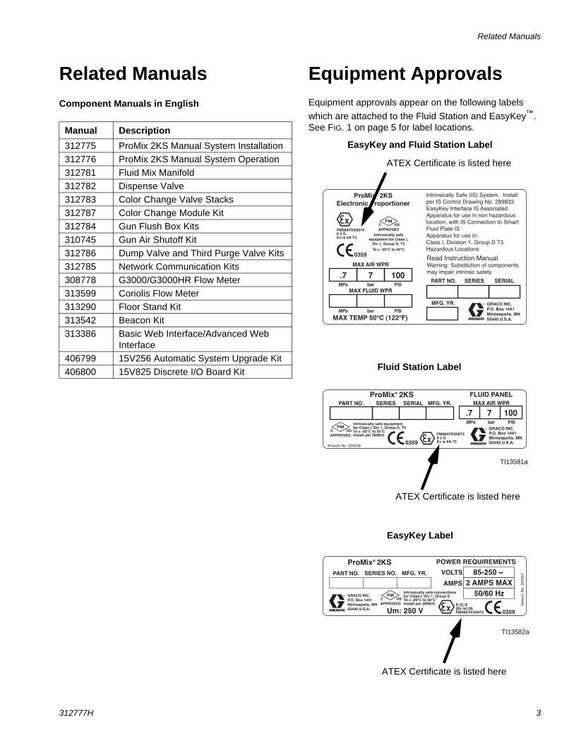
Related ManualsComponent Manuals in English
Equipment ApprovalsEquipment approvals appear on the following labels which are attached to the Fluid Station and EasyKey™. See FIG. 1 on page 5 for label locations.Manual Description
312775 ProMix 2KS Manual System Installation312776 ProMix 2KS Manual System Operation312781 Fluid Mix Manifold312782 Dispense Valve312783 Color Change Valve Stacks312787 Color Change Module Kit312784 Gun Flush Box Kits310745 Gun Air Shutoff Kit312786 Dump Valve and Third Purge Valve Kits312785 Network Communication Kits308778 G3000/G3000HR Flow Meter313599 Coriolis Flow Meter313290 Floor Stand Kit313542 Beacon Kit313386 Basic Web Interface/Advanced Web
Interface406799 15V256 Automatic System Upgrade Kit406800 15V825 Discrete I/O Board Kit
�� � ��������� �
� � ��� ��������� �
� � ��� �
������ �����
��������� ������������������������������� ������������������������ ������
�����
���������� !"#��$�" ��%��#��$!�
������ &�'()���'�*
������ ��������������������������������������������� ����!���"#$#%%�&��'��������� �����(� ����(���������������������)�*������� ����+� �)��������� �����������,�����-������(����������������������+���.�����/+�0�������1%2�*������3� ����
$#��$+�"� ,+�-!!./�%0!$#-��( �++1
��2�13��/%�1�4
��56��'(#�&�'(
( �����7�������8�3������4
3��(��(� ���9���88���$$!�%� �+1��&&88�������
��3�:��
Art
wor
k N
o. 2
9346
7 SERIES NO. MFG. YR.PART NO.
AMPS
VOLTS 85-250 ~ 2 AMPS MAX
POWER REQUIREMENTS
GRACO INC.P.O. Box 1441Minneapolis, MN 55440 U.S.A.
II (2) G[Ex ia] IIAFM08ATEX0072
Intrinsically safe connectionsfor Class I, Div 1, Group DTa = -20°C to 50°CInstall per 289833
C US50/60 Hz
ProMix 2KS®
Um: 250 V
Artwork No. 293538
GRACO INC.P.O. Box 1441Minneapolis, MN 55440 U.S.A.
.7 7MAX AIR WPR
MPa bar PSI
FLUID PANELProMix 2KS
100PART NO. SERIES SERIAL MFG. YR.
C US
Intrinsically safe equipmentfor Class I, Div 1, Group D, T3Ta = -20°C to 50°CInstall per 289833 FM08ATEX0073
II 2 GEx ia IIA T3
®
ATEX Certificate is listed here
ATEX Certificate is listed here
ATEX Certificate is listed here
TI13581a
TI13582a
EasyKey Label
Fluid Station Label
EasyKey and Fluid Station Label
System Configuration and Part Numbers
4 312777H
System Configuration and Part Numbers
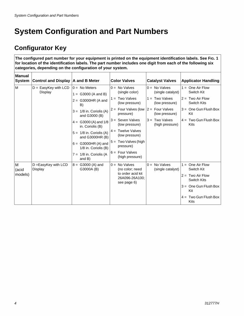
Configurator KeyThe configured part number for your equipment is printed on the equipment identification labels. See FIG. 1 for location of the identification labels. The part number includes one digit from each of the following six categories, depending on the configuration of your system.
Manual System Control and Display A and B Meter Color Valves Catalyst Valves Applicator Handling
M D = EasyKey with LCD Display
0 = No Meters
1 = G3000 (A and B)
2 = G3000HR (A and B)
3 = 1/8 in. Coriolis (A) and G3000 (B)
4 = G3000 (A) and 1/8 in. Coriolis (B)
5 = 1/8 in. Coriolis (A) and G3000HR (B)
6 = G3000HR (A) and 1/8 in. Coriolis (B)
7 = 1/8 in. Coriolis (A and B)
0 = No Valves (single color)
1 = Two Valves (low pressure)
2 = Four Valves (low pressure)
3 = Seven Valves (low pressure)
4 = Twelve Valves (low pressure)
5 = Two Valves (high pressure)
6 = Four Valves (high pressure)
0 = No Valves (single catalyst)
1 = Two Valves (low pressure)
2 = Four Valves (low pressure)
3 = Two Valves (high pressure)
1 = One Air Flow Switch Kit
2 = Two Air Flow Switch Kits
3 = One Gun Flush Box Kit
4 = Two Gun Flush Box Kits
M(acid models)
D =EasyKey with LCD Display
8 = G3000 (A) and G3000A (B)
0 = No Valves (no color; need to order acid kit 26A096-26A100; see page 6)
0 = No Valves (single catalyst)
1 = One Air Flow Switch Kit
2 = Two Air Flow Switch Kits
3 = One Gun Flush Box Kit
4 = Two Gun Flush Box Kits
System Configuration and Part Numbers
312777H 5
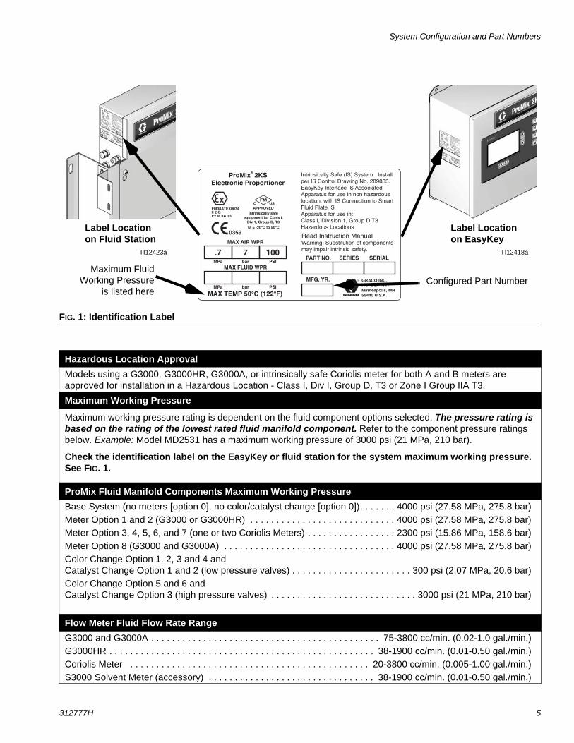
FIG. 1: Identification Label
Hazardous Location ApprovalModels using a G3000, G3000HR, G3000A, or intrinsically safe Coriolis meter for both A and B meters are approved for installation in a Hazardous Location - Class I, Div I, Group D, T3 or Zone I Group IIA T3.
Maximum Working Pressure
Maximum working pressure rating is dependent on the fluid component options selected. The pressure rating is based on the rating of the lowest rated fluid manifold component. Refer to the component pressure ratings below. Example: Model MD2531 has a maximum working pressure of 3000 psi (21 MPa, 210 bar).
Check the identification label on the EasyKey or fluid station for the system maximum working pressure. See FIG. 1.
ProMix Fluid Manifold Components Maximum Working PressureBase System (no meters [option 0], no color/catalyst change [option 0]). . . . . . . 4000 psi (27.58 MPa, 275.8 bar)Meter Option 1 and 2 (G3000 or G3000HR) . . . . . . . . . . . . . . . . . . . . . . . . . . . . 4000 psi (27.58 MPa, 275.8 bar)Meter Option 3, 4, 5, 6, and 7 (one or two Coriolis Meters) . . . . . . . . . . . . . . . . . 2300 psi (15.86 MPa, 158.6 bar)Meter Option 8 (G3000 and G3000A) . . . . . . . . . . . . . . . . . . . . . . . . . . . . . . . . . 4000 psi (27.58 MPa, 275.8 bar)Color Change Option 1, 2, 3 and 4 and Catalyst Change Option 1 and 2 (low pressure valves) . . . . . . . . . . . . . . . . . . . . . . . 300 psi (2.07 MPa, 20.6 bar)Color Change Option 5 and 6 and Catalyst Change Option 3 (high pressure valves) . . . . . . . . . . . . . . . . . . . . . . . . . . . . 3000 psi (21 MPa, 210 bar)
Flow Meter Fluid Flow Rate RangeG3000 and G3000A . . . . . . . . . . . . . . . . . . . . . . . . . . . . . . . . . . . . . . . . . . . . 75-3800 cc/min. (0.02-1.0 gal./min.)G3000HR . . . . . . . . . . . . . . . . . . . . . . . . . . . . . . . . . . . . . . . . . . . . . . . . . . . 38-1900 cc/min. (0.01-0.50 gal./min.)Coriolis Meter . . . . . . . . . . . . . . . . . . . . . . . . . . . . . . . . . . . . . . . . . . . . . . 20-3800 cc/min. (0.005-1.00 gal./min.)S3000 Solvent Meter (accessory) . . . . . . . . . . . . . . . . . . . . . . . . . . . . . . . . 38-1900 cc/min. (0.01-0.50 gal./min.)
�� � ��������� �
� � ��� ��������� �
� � ��� �
������ �����
��������� ������������������������������� ������������������������ ������
�����
���������� !"#��$�" ��%��#��$!�
������ &�'()���'�*
������ ��������������������������������������������� ����!���"#$#%%�&��'��������� �����(� ����(���������������������)�*������� ����+� �)��������� �����������,�����-������(����������������������+���.�����/+�0�������1%2�*������3� ����
$#��$+�"� ,+�-!!./�%0!$#-��( �++1
��2�13��/%�1�4
��56��'(#�&�'(
( �����7�������8�3������4
3��(��(� ���9���88���$$!�%� �+1��&&88�������
��3�:��
Label Location on EasyKey
Label Location on Fluid Station
Maximum FluidWorking Pressure
is listed here
TI12418aTI12423a
Configured Part Number
Accessories
6 312777H
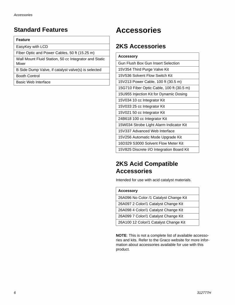
Standard Features Accessories
2KS Accessories
2KS Acid Compatible AccessoriesIntended for use with acid catalyst materials.
NOTE: This is not a complete list of available accesso-ries and kits. Refer to the Graco website for more infor-mation about accessories available for use with this product.
Feature
EasyKey with LCD
Fiber Optic and Power Cables, 50 ft (15.25 m)
Wall Mount Fluid Station, 50 cc Integrator and Static Mixer
B Side Dump Valve, if catalyst valve(s) is selected
Booth Control
Basic Web Interface
Accessory
Gun Flush Box Gun Insert Selection
15V354 Third Purge Valve Kit
15V536 Solvent Flow Switch Kit
15V213 Power Cable, 100 ft (30.5 m)
15G710 Fiber Optic Cable, 100 ft (30.5 m)
15U955 Injection Kit for Dynamic Dosing
15V034 10 cc Integrator Kit
15V033 25 cc Integrator Kit
15V021 50 cc Integrator Kit
24B618 100 cc Integrator Kit
15W034 Strobe Light Alarm Indicator Kit
15V337 Advanced Web Interface
15V256 Automatic Mode Upgrade Kit
16D329 S3000 Solvent Flow Meter Kit
15V825 Discrete I/O Integration Board Kit
Accessory
26A096 No Color /1 Catalyst Change Kit
26A097 2 Color/1 Catalyst Change Kit
26A098 4 Color/1 Catalyst Change Kit
26A099 7 Color/1 Catalyst Change Kit
26A100 12 Color/1 Catalyst Change Kit
Warnings
312777H 7
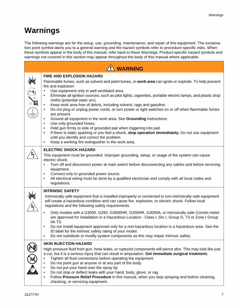
WarningsThe following warnings are for the setup, use, grounding, maintenance, and repair of this equipment. The exclama-tion point symbol alerts you to a general warning and the hazard symbols refer to procedure-specific risks. When these symbols appear in the body of this manual, refer back to these Warnings. Product-specific hazard symbols and warnings not covered in this section may appear throughout the body of this manual where applicable.
WARNINGFIRE AND EXPLOSION HAZARD Flammable fumes, such as solvent and paint fumes, in work area can ignite or explode. To help prevent fire and explosion:• Use equipment only in well ventilated area.• Eliminate all ignition sources; such as pilot lights, cigarettes, portable electric lamps, and plastic drop
cloths (potential static arc). • Keep work area free of debris, including solvent, rags and gasoline.• Do not plug or unplug power cords, or turn power or light switches on or off when flammable fumes
are present.• Ground all equipment in the work area. See Grounding instructions.• Use only grounded hoses.• Hold gun firmly to side of grounded pail when triggering into pail.• If there is static sparking or you feel a shock, stop operation immediately. Do not use equipment
until you identify and correct the problem.• Keep a working fire extinguisher in the work area.
ELECTRIC SHOCK HAZARD This equipment must be grounded. Improper grounding, setup, or usage of the system can cause electric shock.• Turn off and disconnect power at main switch before disconnecting any cables and before servicing
equipment.• Connect only to grounded power source.• All electrical wiring must be done by a qualified electrician and comply with all local codes and
regulations.
INTRINSIC SAFETYIntrinsically safe equipment that is installed improperly or connected to non-intrinsically safe equipment will create a hazardous condition and can cause fire, explosion, or electric shock. Follow local regulations and the following safety requirements.
• Only models with a G3000, G250, G3000HR, G250HR, G3000A, or intrinsically safe Coriolis meter are approved for installation in a Hazardous Location - Class I, Div I, Group D, T3 or Zone I Group IIA T3.
• Do not install equipment approved only for a non-hazardous location in a hazardous area. See the ID label for the intrinsic safety rating of your model.
• Do not substitute or modify system components as this may impair intrinsic safety.
SKIN INJECTION HAZARD High-pressure fluid from gun, hose leaks, or ruptured components will pierce skin. This may look like just a cut, but it is a serious injury that can result in amputation. Get immediate surgical treatment.• Tighten all fluid connections before operating the equipment.• Do not point gun at anyone or at any part of the body.• Do not put your hand over the spray tip.• Do not stop or deflect leaks with your hand, body, glove, or rag.• Follow Pressure Relief Procedure in this manual, when you stop spraying and before cleaning,
checking, or servicing equipment.
Warnings
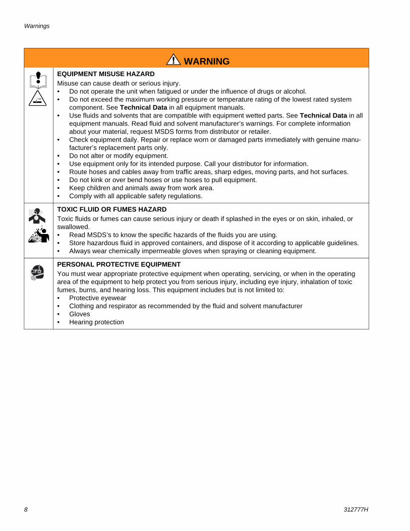
8 312777H
EQUIPMENT MISUSE HAZARD Misuse can cause death or serious injury.• Do not operate the unit when fatigued or under the influence of drugs or alcohol.• Do not exceed the maximum working pressure or temperature rating of the lowest rated system
component. See Technical Data in all equipment manuals.• Use fluids and solvents that are compatible with equipment wetted parts. See Technical Data in all
equipment manuals. Read fluid and solvent manufacturer’s warnings. For complete information about your material, request MSDS forms from distributor or retailer.
• Check equipment daily. Repair or replace worn or damaged parts immediately with genuine manu-facturer’s replacement parts only.
• Do not alter or modify equipment.• Use equipment only for its intended purpose. Call your distributor for information.• Route hoses and cables away from traffic areas, sharp edges, moving parts, and hot surfaces.• Do not kink or over bend hoses or use hoses to pull equipment.• Keep children and animals away from work area.• Comply with all applicable safety regulations.
TOXIC FLUID OR FUMES HAZARD Toxic fluids or fumes can cause serious injury or death if splashed in the eyes or on skin, inhaled, or swallowed.• Read MSDS’s to know the specific hazards of the fluids you are using.• Store hazardous fluid in approved containers, and dispose of it according to applicable guidelines.• Always wear chemically impermeable gloves when spraying or cleaning equipment.
PERSONAL PROTECTIVE EQUIPMENT You must wear appropriate protective equipment when operating, servicing, or when in the operating area of the equipment to help protect you from serious injury, including eye injury, inhalation of toxic fumes, burns, and hearing loss. This equipment includes but is not limited to:• Protective eyewear • Clothing and respirator as recommended by the fluid and solvent manufacturer• Gloves• Hearing protection
WARNING
Important Two-Component Material Information
312777H 9
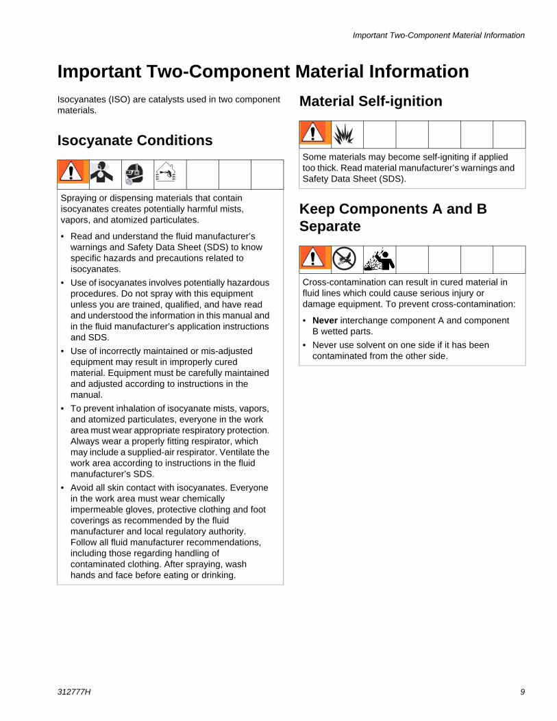
Important Two-Component Material InformationIsocyanates (ISO) are catalysts used in two component materials.
Isocyanate Conditions
Material Self-ignition
Keep Components A and B Separate
Spraying or dispensing materials that contain isocyanates creates potentially harmful mists, vapors, and atomized particulates.
• Read and understand the fluid manufacturer’s warnings and Safety Data Sheet (SDS) to know specific hazards and precautions related to isocyanates.
• Use of isocyanates involves potentially hazardous procedures. Do not spray with this equipment unless you are trained, qualified, and have read and understood the information in this manual and in the fluid manufacturer’s application instructions and SDS.
• Use of incorrectly maintained or mis-adjusted equipment may result in improperly cured material. Equipment must be carefully maintained and adjusted according to instructions in the manual.
• To prevent inhalation of isocyanate mists, vapors, and atomized particulates, everyone in the work area must wear appropriate respiratory protection. Always wear a properly fitting respirator, which may include a supplied-air respirator. Ventilate the work area according to instructions in the fluid manufacturer’s SDS.
• Avoid all skin contact with isocyanates. Everyone in the work area must wear chemically impermeable gloves, protective clothing and foot coverings as recommended by the fluid manufacturer and local regulatory authority. Follow all fluid manufacturer recommendations, including those regarding handling of contaminated clothing. After spraying, wash hands and face before eating or drinking.
Some materials may become self-igniting if applied too thick. Read material manufacturer’s warnings and Safety Data Sheet (SDS).
Cross-contamination can result in cured material in fluid lines which could cause serious injury or damage equipment. To prevent cross-contamination:
• Never interchange component A and component B wetted parts.
• Never use solvent on one side if it has been contaminated from the other side.
Important Two-Component Material Information
10 312777H
Moisture Sensitivity of IsocyanatesExposure to moisture (such as humidity) will cause ISO to partially cure; forming small, hard, abrasive crystals, which become suspended in the fluid. Eventually a film will form on the surface and the ISO will begin to gel, increasing in viscosity.
NOTE: The amount of film formation and rate of crystal-lization varies depending on the blend of ISO, the humidity, and the temperature.
Changing Materials
NOTICEPartially cured ISO will reduce performance and the life of all wetted parts.
• Always use a sealed container with a desiccant dryer in the vent, or a nitrogen atmosphere. Never store ISO in an open container.
• Keep the ISO pump wet cup or reservoir (if installed) filled with appropriate lubricant. The lubricant creates a barrier between the ISO and the atmosphere.
• Use only moisture-proof hoses compatible with ISO.
• Never use reclaimed solvents, which may contain moisture. Always keep solvent containers closed when not in use.
• Always lubricate threaded parts with an appropriate lubricant when reassembling.
NOTICEChanging the material types used in your equipment requires special attention to avoid equipment damage and downtime.
• When changing materials, flush the equipment multiple times to ensure it is thoroughly clean.
• Always clean the fluid inlet strainers after flushing.
• Check with your material manufacturer for chemical compatibility.
• When changing between epoxies and urethanes or polyureas, disassemble and clean all fluid components and change hoses. Epoxies often have amines on the B (hardener) side. Polyureas often have aminies on the A (resin) side.
Important Acid Catalyst Information
312777H 11
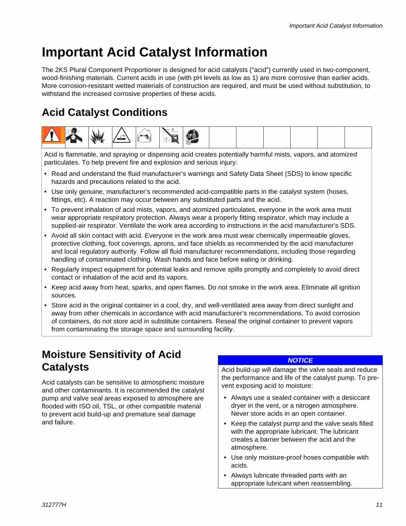
Important Acid Catalyst InformationThe 2KS Plural Component Proportioner is designed for acid catalysts (“acid”) currently used in two-component, wood-finishing materials. Current acids in use (with pH levels as low as 1) are more corrosive than earlier acids. More corrosion-resistant wetted materials of construction are required, and must be used without substitution, to withstand the increased corrosive properties of these acids.
Acid Catalyst Conditions
Moisture Sensitivity of Acid CatalystsAcid catalysts can be sensitive to atmospheric moisture and other contaminants. It is recommended the catalyst pump and valve seal areas exposed to atmosphere are flooded with ISO oil, TSL, or other compatible material to prevent acid build-up and premature seal damage and failure.
Acid is flammable, and spraying or dispensing acid creates potentially harmful mists, vapors, and atomized particulates. To help prevent fire and explosion and serious injury:
• Read and understand the fluid manufacturer’s warnings and Safety Data Sheet (SDS) to know specific hazards and precautions related to the acid.
• Use only genuine, manufacturer’s recommended acid-compatible parts in the catalyst system (hoses, fittings, etc). A reaction may occur between any substituted parts and the acid.
• To prevent inhalation of acid mists, vapors, and atomized particulates, everyone in the work area must wear appropriate respiratory protection. Always wear a properly fitting respirator, which may include a supplied-air respirator. Ventilate the work area according to instructions in the acid manufacturer’s SDS.
• Avoid all skin contact with acid. Everyone in the work area must wear chemically impermeable gloves, protective clothing, foot coverings, aprons, and face shields as recommended by the acid manufacturer and local regulatory authority. Follow all fluid manufacturer recommendations, including those regarding handling of contaminated clothing. Wash hands and face before eating or drinking.
• Regularly inspect equipment for potential leaks and remove spills promptly and completely to avoid direct contact or inhalation of the acid and its vapors.
• Keep acid away from heat, sparks, and open flames. Do not smoke in the work area. Eliminate all ignition sources.
• Store acid in the original container in a cool, dry, and well-ventilated area away from direct sunlight and away from other chemicals in accordance with acid manufacturer’s recommendations. To avoid corrosion of containers, do not store acid in substitute containers. Reseal the original container to prevent vapors from contaminating the storage space and surrounding facility.
NOTICEAcid build-up will damage the valve seals and reduce the performance and life of the catalyst pump. To pre-vent exposing acid to moisture:
• Always use a sealed container with a desiccant dryer in the vent, or a nitrogen atmosphere. Never store acids in an open container.
• Keep the catalyst pump and the valve seals filled with the appropriate lubricant. The lubricant creates a barrier between the acid and the atmosphere.
• Use only moisture-proof hoses compatible with acids.
• Always lubricate threaded parts with an appropriate lubricant when reassembling.
Grounding
12 312777H
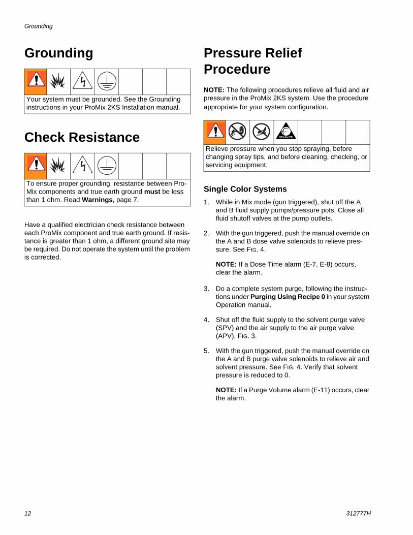
Grounding
Check Resistance
Have a qualified electrician check resistance between each ProMix component and true earth ground. If resis-tance is greater than 1 ohm, a different ground site may be required. Do not operate the system until the problem is corrected.
Pressure Relief ProcedureNOTE: The following procedures relieve all fluid and air pressure in the ProMix 2KS system. Use the procedure appropriate for your system configuration.
Single Color Systems1. While in Mix mode (gun triggered), shut off the A
and B fluid supply pumps/pressure pots. Close all fluid shutoff valves at the pump outlets.
2. With the gun triggered, push the manual override on the A and B dose valve solenoids to relieve pres-sure. See FIG. 4.
NOTE: If a Dose Time alarm (E-7, E-8) occurs, clear the alarm.
3. Do a complete system purge, following the instruc-tions under Purging Using Recipe 0 in your system Operation manual.
4. Shut off the fluid supply to the solvent purge valve (SPV) and the air supply to the air purge valve (APV), FIG. 3.
5. With the gun triggered, push the manual override on the A and B purge valve solenoids to relieve air and solvent pressure. See FIG. 4. Verify that solvent pressure is reduced to 0.
NOTE: If a Purge Volume alarm (E-11) occurs, clear the alarm.
Your system must be grounded. See the Grounding instructions in your ProMix 2KS Installation manual.
To ensure proper grounding, resistance between Pro-Mix components and true earth ground must be less than 1 ohm. Read Warnings, page 7.
Relieve pressure when you stop spraying, before changing spray tips, and before cleaning, checking, or servicing equipment.
Pressure Relief Procedure
312777H 13
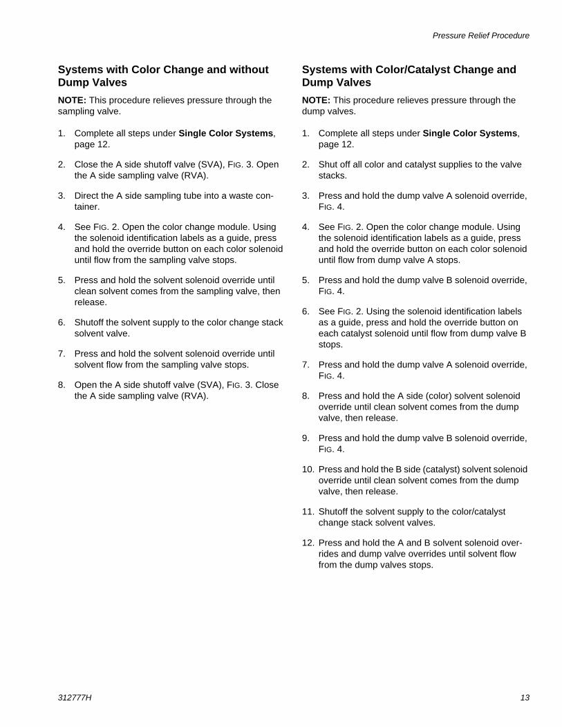
Systems with Color Change and without Dump ValvesNOTE: This procedure relieves pressure through the sampling valve.
1. Complete all steps under Single Color Systems, page 12.
2. Close the A side shutoff valve (SVA), FIG. 3. Open the A side sampling valve (RVA).
3. Direct the A side sampling tube into a waste con-tainer.
4. See FIG. 2. Open the color change module. Using the solenoid identification labels as a guide, press and hold the override button on each color solenoid until flow from the sampling valve stops.
5. Press and hold the solvent solenoid override until clean solvent comes from the sampling valve, then release.
6. Shutoff the solvent supply to the color change stack solvent valve.
7. Press and hold the solvent solenoid override until solvent flow from the sampling valve stops.
8. Open the A side shutoff valve (SVA), FIG. 3. Close the A side sampling valve (RVA).
Systems with Color/Catalyst Change and Dump ValvesNOTE: This procedure relieves pressure through the dump valves.
1. Complete all steps under Single Color Systems, page 12.
2. Shut off all color and catalyst supplies to the valve stacks.
3. Press and hold the dump valve A solenoid override, FIG. 4.
4. See FIG. 2. Open the color change module. Using the solenoid identification labels as a guide, press and hold the override button on each color solenoid until flow from dump valve A stops.
5. Press and hold the dump valve B solenoid override, FIG. 4.
6. See FIG. 2. Using the solenoid identification labels as a guide, press and hold the override button on each catalyst solenoid until flow from dump valve B stops.
7. Press and hold the dump valve A solenoid override, FIG. 4.
8. Press and hold the A side (color) solvent solenoid override until clean solvent comes from the dump valve, then release.
9. Press and hold the dump valve B solenoid override, FIG. 4.
10. Press and hold the B side (catalyst) solvent solenoid override until clean solvent comes from the dump valve, then release.
11. Shutoff the solvent supply to the color/catalyst change stack solvent valves.
12. Press and hold the A and B solvent solenoid over-rides and dump valve overrides until solvent flow from the dump valves stops.
Pressure Relief Procedure
14 312777H
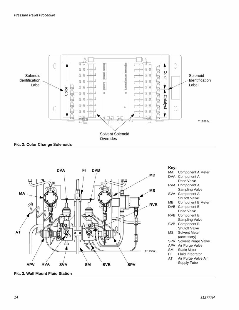
FIG. 2: Color Change Solenoids
TI12826a
Solvent Solenoid Overrides
Solenoid Identification Label
SolenoidIdentification
Label
Col
or
Color
Catalyst
FIG. 3. Wall Mount Fluid Station
Key:MA Component A MeterDVA Component A
Dose ValveRVA Component A
Sampling ValveSVA Component A
Shutoff ValveMB Component B MeterDVB Component B
Dose ValveRVB Component B
Sampling ValveSVB Component B
Shutoff ValveMS Solvent Meter
(accessory)SPV Solvent Purge ValveAPV Air Purge ValveSM Static MixerFI Fluid IntegratorAT Air Purge Valve Air
Supply Tube
TI12556b
MA
MBDVB
MS
SPV
DVA
APV SM
FI
SVA SVB
RVB
RVA
AT
Troubleshooting
312777H 15
Troubleshooting
NOTE: Do not use the fluid in the line that was dis-pensed off ratio as it may not cure properly.
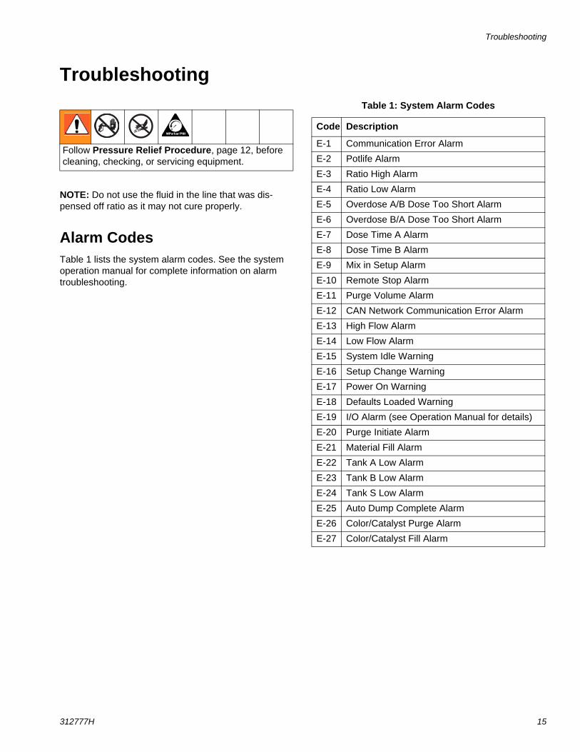
Alarm CodesTable 1 lists the system alarm codes. See the system operation manual for complete information on alarm troubleshooting.
Follow Pressure Relief Procedure, page 12, before cleaning, checking, or servicing equipment.
Table 1: System Alarm Codes
Code Description
E-1 Communication Error Alarm
E-2 Potlife Alarm
E-3 Ratio High Alarm
E-4 Ratio Low Alarm
E-5 Overdose A/B Dose Too Short Alarm
E-6 Overdose B/A Dose Too Short Alarm
E-7 Dose Time A Alarm
E-8 Dose Time B Alarm
E-9 Mix in Setup Alarm
E-10 Remote Stop Alarm
E-11 Purge Volume Alarm
E-12 CAN Network Communication Error Alarm
E-13 High Flow Alarm
E-14 Low Flow Alarm
E-15 System Idle Warning
E-16 Setup Change Warning
E-17 Power On Warning
E-18 Defaults Loaded Warning
E-19 I/O Alarm (see Operation Manual for details)
E-20 Purge Initiate Alarm
E-21 Material Fill Alarm
E-22 Tank A Low Alarm
E-23 Tank B Low Alarm
E-24 Tank S Low Alarm
E-25 Auto Dump Complete Alarm
E-26 Color/Catalyst Purge Alarm
E-27 Color/Catalyst Fill Alarm
Troubleshooting
16 312777H
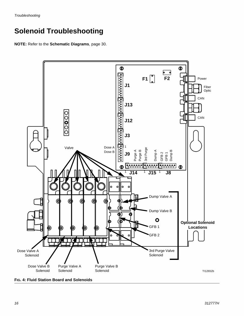
Solenoid Troubleshooting
NOTE: Refer to the Schematic Diagrams, page 30.
FIG. 4: Fluid Station Board and Solenoids
TI12652b
GFB 1
GFB 2
Dump Valve A
Purge Valve B Solenoid
Purge Valve A Solenoid
Dose Valve BSolenoid
Dose Valve ASolenoid
Optional Solenoid Locations
1
Dose ADose B
Pur
ge B
Dum
p A
3rd
Pur
ge
Dum
p B
GF
B 2
GF
B 1
Power
Fiber Optic
CAN
CAN
J1
J13
J12
J3
J9
J14 J15 J8
3rd Purge Valve Solenoid
Dump Valve B
Valve
Pur
ge A
1 1
1
F2F1
Troubleshooting
312777H 17
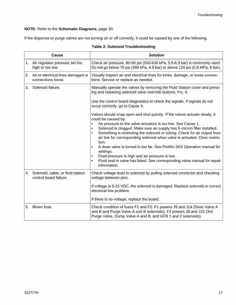
NOTE: Refer to the Schematic Diagrams, page 30.
If the dispense or purge valves are not turning on or off correctly, it could be caused by one of the following.
Table 2: Solenoid Troubleshooting
Cause Solution
1. Air regulator pressure set too high or too low.
Check air pressure. 80-90 psi (550-630 kPa, 5.5-6.3 bar) is commonly used. Do not go below 70 psi (490 kPa, 4.9 bar) or above 120 psi (0.8 MPa, 8 bar),
2. Air or electrical lines damaged or connections loose.
Visually inspect air and electrical lines for kinks, damage, or loose connec-tions. Service or replace as needed.
3. Solenoid failure. Manually operate the valves by removing the Fluid Station cover and press-ing and releasing solenoid valve override buttons. FIG. 4.
Use the control board diagnostics to check the signals. If signals do not occur correctly, go to Cause 4.
Valves should snap open and shut quickly. If the valves actuate slowly, it could be caused by:• Air pressure to the valve actuators is too low. See Cause 1.• Solenoid is clogged. Make sure air supply has 5 micron filter installed.• Something is restricting the solenoid or tubing. Check for air output from
air line for corresponding solenoid when valve is actuated. Clear restric-tion.
• A dose valve is turned in too far. See ProMix 2KS Operation manual for settings.
• Fluid pressure is high and air pressure is low.• Fluid seal in valve has failed. See corresponding valve manual for repair
information.
4. Solenoid, cable, or fluid station control board failure.
Check voltage level to solenoid by pulling solenoid connector and checking voltage between pins.
If voltage is 9-15 VDC, the solenoid is damaged. Replace solenoid or correct electrical line problem.
If there is no voltage, replace the board.
5. Blown fuse. Check condition of fuses F1 and F2. F1 powers J9 and J14 (Dose Valve A and B and Purge Valve A and B solenoids). F2 powers J8 and J15 (3rd Purge Valve, Dump Valve A and B, and GFB 1 and 2 solenoids).
Troubleshooting
18 312777H
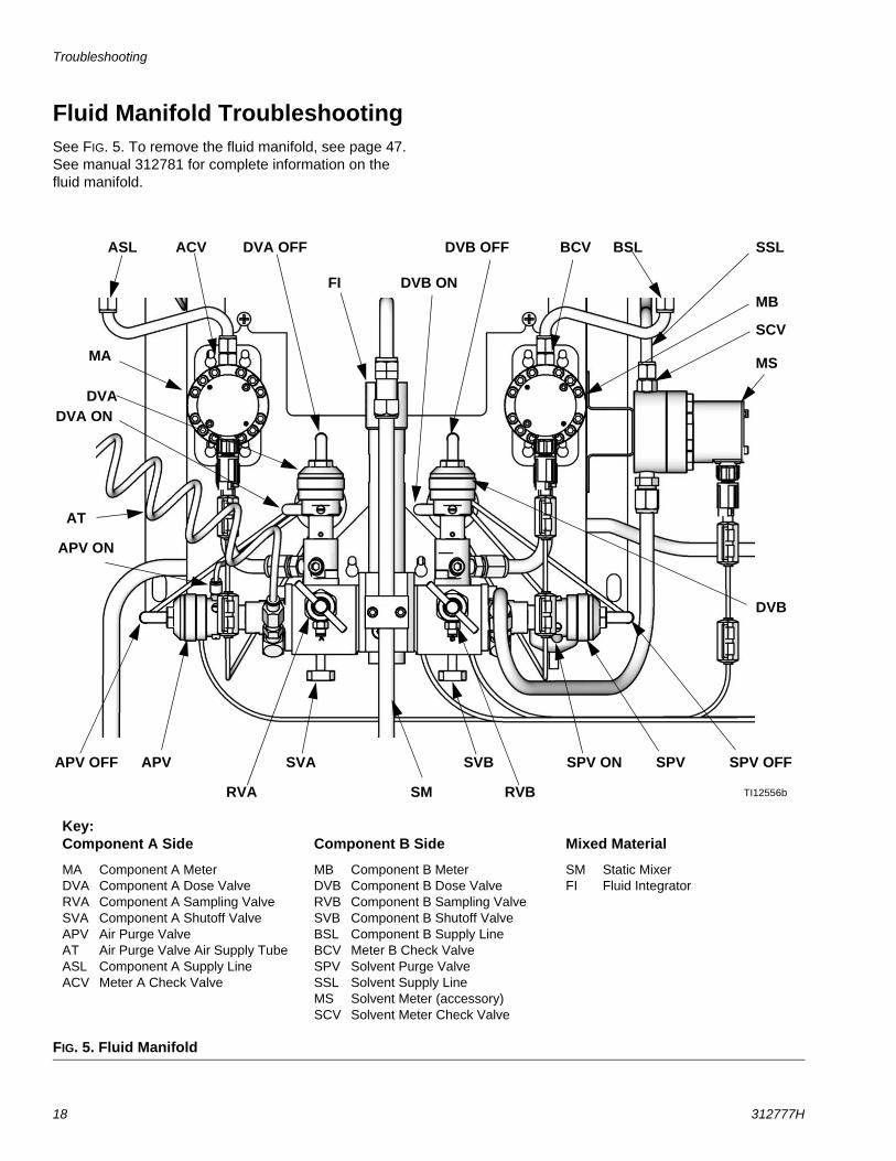
Fluid Manifold TroubleshootingSee FIG. 5. To remove the fluid manifold, see page 47. See manual 312781 for complete information on the fluid manifold.
FIG. 5. Fluid Manifold
Key:Component A Side
MA Component A MeterDVA Component A Dose ValveRVA Component A Sampling ValveSVA Component A Shutoff ValveAPV Air Purge ValveAT Air Purge Valve Air Supply TubeASL Component A Supply LineACV Meter A Check Valve
Component B Side
MB Component B MeterDVB Component B Dose ValveRVB Component B Sampling ValveSVB Component B Shutoff ValveBSL Component B Supply LineBCV Meter B Check ValveSPV Solvent Purge ValveSSL Solvent Supply LineMS Solvent Meter (accessory)SCV Solvent Meter Check Valve
Mixed Material
SM Static MixerFI Fluid Integrator
TI12556b
MA
MB
DVB
MS
SPV
DVA
APV
SM
FI
SVA SVB
RVBRVA
AT
DVA OFF
DVA ON
APV ON
APV OFF SPV OFFSPV ON
DVB OFF
DVB ON
ASL BSL SSLACV BCV
SCV
Troubleshooting
312777H 19
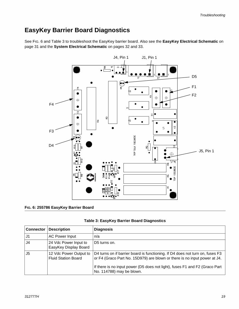
EasyKey Barrier Board Diagnostics
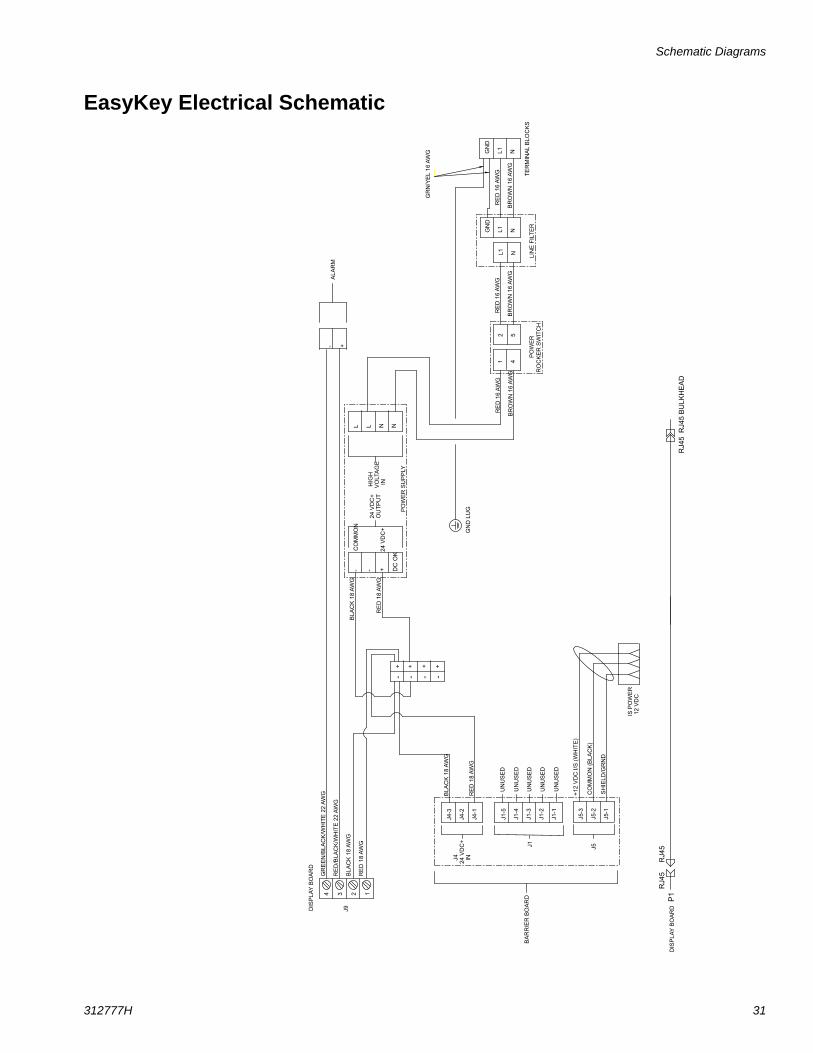
See FIG. 6 and Table 3 to troubleshoot the EasyKey barrier board. Also see the EasyKey Electrical Schematic on page 31 and the System Electrical Schematic on pages 32 and 33.
FIG. 6: 255786 EasyKey Barrier Board
J5, Pin 1
J1, Pin 1J4, Pin 1
D4
D5
F4
F3
F2
F1
Table 3: EasyKey Barrier Board Diagnostics
Connector Description Diagnosis
J1 AC Power Input n/a
J4 24 Vdc Power Input to EasyKey Display Board
D5 turns on.
J5 12 Vdc Power Output to Fluid Station Board
D4 turns on if barrier board is functioning. If D4 does not turn on, fuses F3 or F4 (Graco Part No. 15D979) are blown or there is no input power at J4.
If there is no input power (D5 does not light), fuses F1 and F2 (Graco Part No. 114788) may be blown.
Troubleshooting
20 312777H
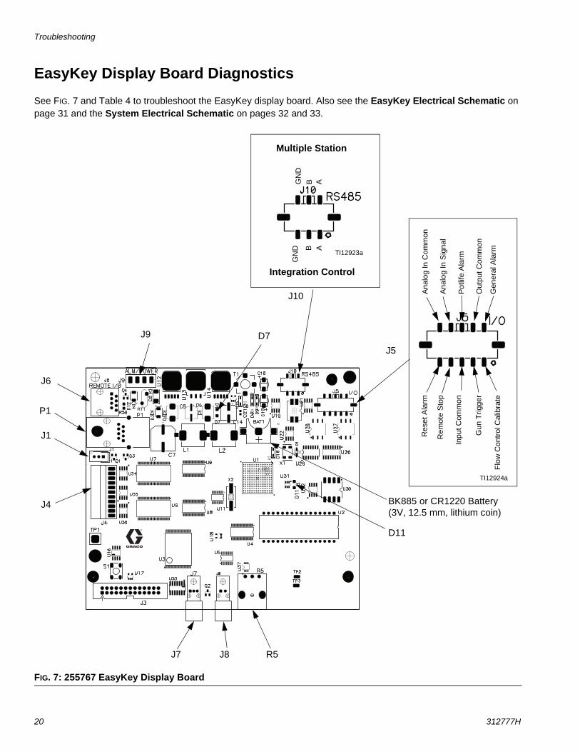
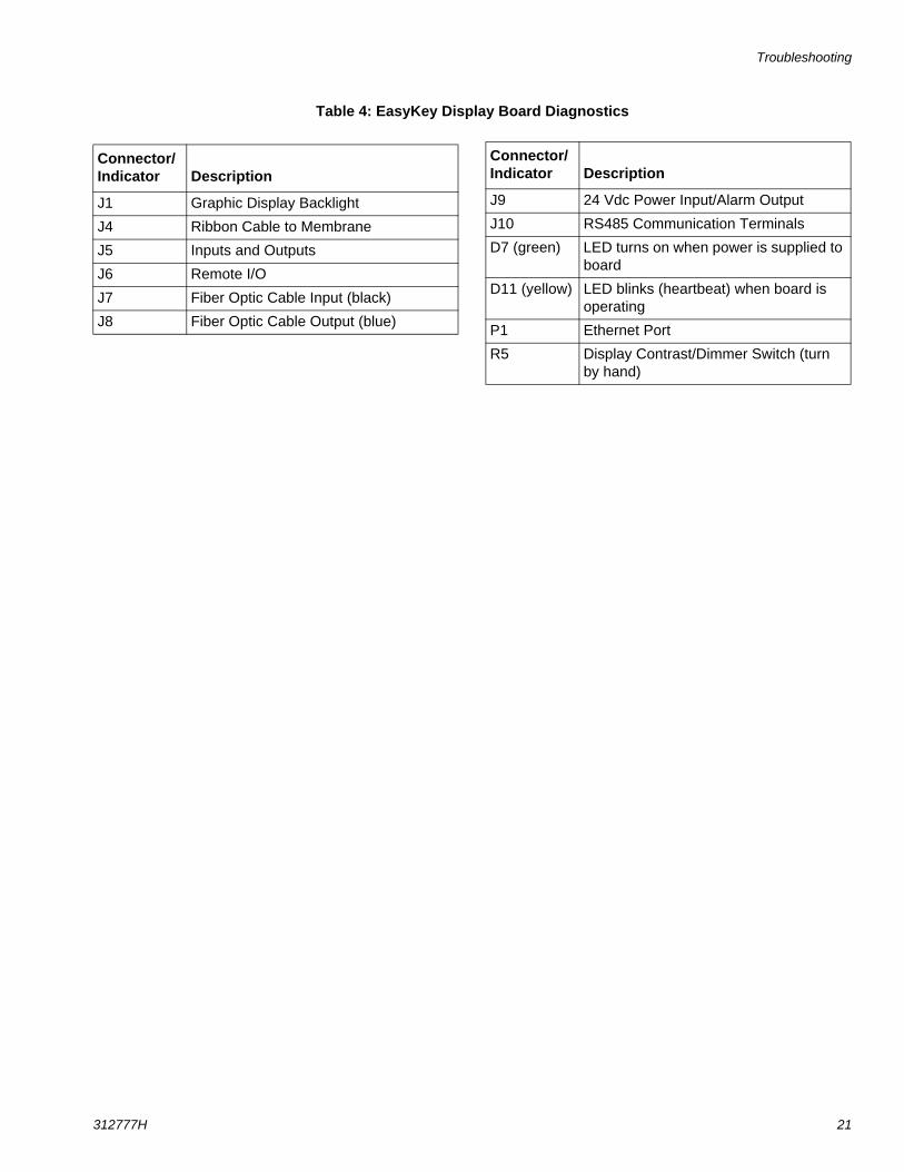
EasyKey Display Board Diagnostics
See FIG. 7 and Table 4 to troubleshoot the EasyKey display board. Also see the EasyKey Electrical Schematic on page 31 and the System Electrical Schematic on pages 32 and 33.
FIG. 7: 255767 EasyKey Display Board
TI12924a
Ana
log
In C
omm
onR
eset
Ala
rm
Rem
ote
Sto
p
Inpu
t Com
mon
Gun
Trig
ger
Flo
w C
ontr
ol C
alib
rate
Ana
log
In S
igna
l
Pot
life
Ala
rm
Out
put C
omm
on
Gen
eral
Ala
rm
RT1
J4
J9
J8J7
J1
D11
D7
TI12923a
Multiple Station
Integration Control
GN
DG
ND
ABAB
BK885 or CR1220 Battery (3V, 12.5 mm, lithium coin)
R5
P1
J6
J5
J10
Troubleshooting
312777H 21
Table 4: EasyKey Display Board Diagnostics
Connector/Indicator Description
J1 Graphic Display Backlight
J4 Ribbon Cable to Membrane
J5 Inputs and Outputs
J6 Remote I/O
J7 Fiber Optic Cable Input (black)
J8 Fiber Optic Cable Output (blue)
J9 24 Vdc Power Input/Alarm Output
J10 RS485 Communication Terminals
D7 (green) LED turns on when power is supplied to board
D11 (yellow) LED blinks (heartbeat) when board is operating
P1 Ethernet Port
R5 Display Contrast/Dimmer Switch (turn by hand)
Connector/Indicator Description

Troubleshooting
22 312777H
Troubleshooting
312777H 23
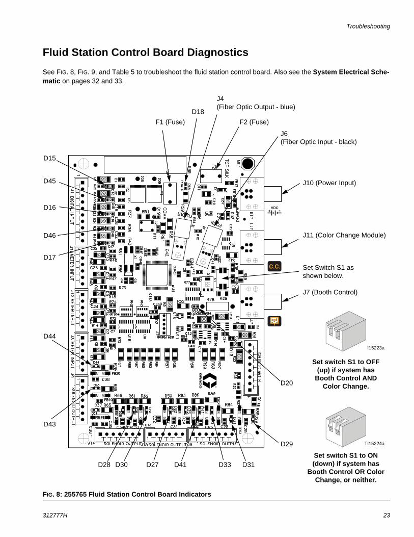
Fluid Station Control Board Diagnostics
See FIG. 8, FIG. 9, and Table 5 to troubleshoot the fluid station control board. Also see the System Electrical Sche-matic on pages 32 and 33.
FIG. 8: 255765 Fluid Station Control Board Indicators
Set switch S1 to ON (down) if system has
Booth Control OR Color Change, or neither.
TI15224a
J10 (Power Input)
J11 (Color Change Module)
J7 (Booth Control)
D15
D45
D16
D46
D17
D44
D43
D28 D30 D27 D41 D33 D31
D29
D20
D18
J4(Fiber Optic Output - blue)
J6(Fiber Optic Input - black)
F2 (Fuse)
Set switch S1 to OFF (up) if system has
Booth Control AND Color Change.
TI15223a
Set Switch S1 as shown below.
F1 (Fuse)
Troubleshooting
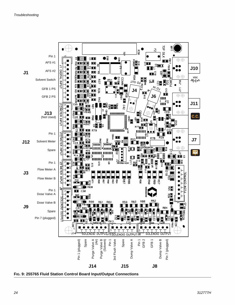
24 312777H
FIG. 9: 255765 Fluid Station Control Board Input/Output Connections
+ ++ + ++ + ++
+
+
+
+
s
G+
s
G
AFS #1
AFS #2
Solvent Switch
GFB 1 PS
GFB 2 PS
(Not Used)
Solvent Meter
Spare
Flow Meter A
Spare
Flow Meter B
Dose Valve A
Dose Valve B
Spa
re
Pur
ge V
alve
A(A
ir)
Pur
ge V
alve
B(S
olve
nt)
Spa
re
Dum
p V
alve
A
3rd
Flus
h V
alve
Dum
p V
alve
B
GF
B 2
GF
B 1
J1
J13
J12
J3
J9
J14 J15 J8
+
s
G+
s
G
Pin 1
J6J4
J10
J11
J7Pin 1
Pin 1
Pin 1
Pin
1 (p
lugg
ed)
Pin 7 (plugged)
Pin
1
Pin
1
Pin
7 (p
lugg
ed)
Troubleshooting
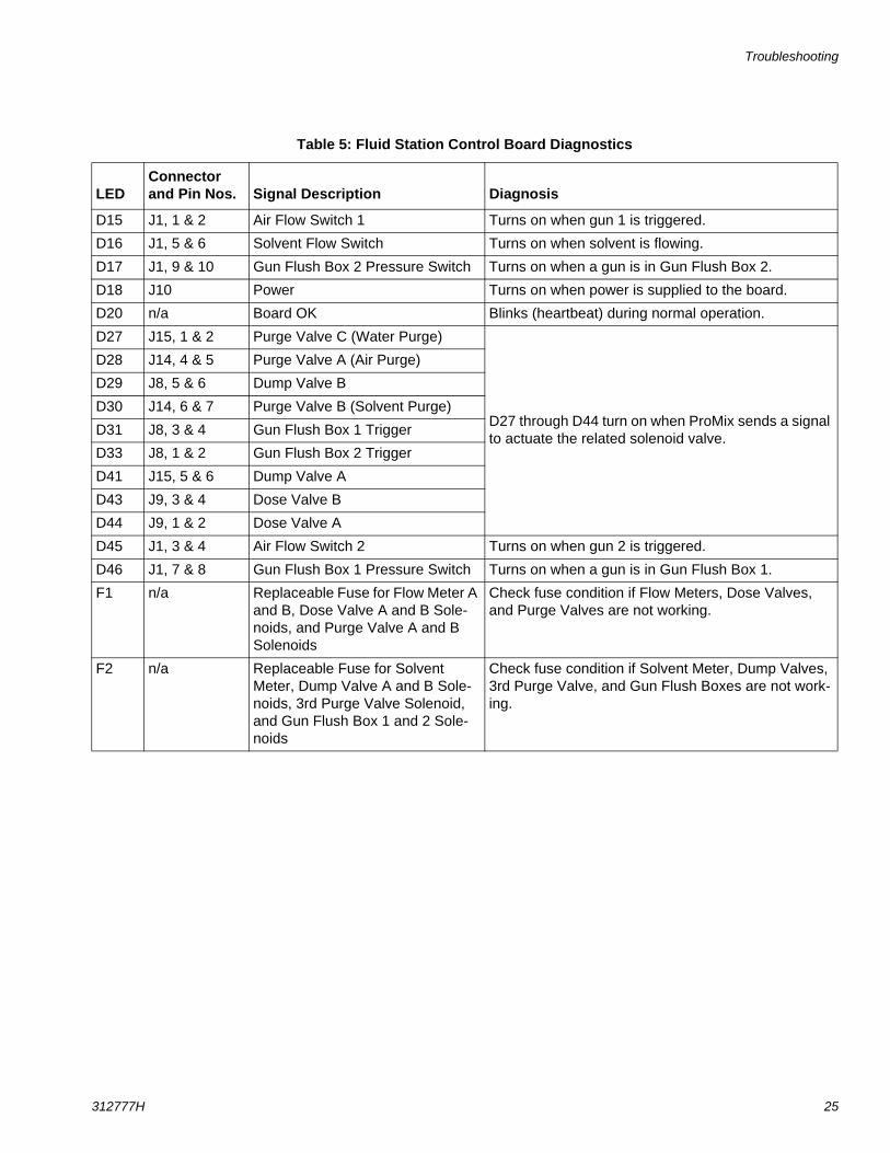
312777H 25
Table 5: Fluid Station Control Board Diagnostics
LED Connector and Pin Nos. Signal Description Diagnosis
D15 J1, 1 & 2 Air Flow Switch 1 Turns on when gun 1 is triggered.
D16 J1, 5 & 6 Solvent Flow Switch Turns on when solvent is flowing.
D17 J1, 9 & 10 Gun Flush Box 2 Pressure Switch Turns on when a gun is in Gun Flush Box 2.
D18 J10 Power Turns on when power is supplied to the board.
D20 n/a Board OK Blinks (heartbeat) during normal operation.
D27 J15, 1 & 2 Purge Valve C (Water Purge)
D27 through D44 turn on when ProMix sends a signal to actuate the related solenoid valve.
D28 J14, 4 & 5 Purge Valve A (Air Purge)
D29 J8, 5 & 6 Dump Valve B
D30 J14, 6 & 7 Purge Valve B (Solvent Purge)
D31 J8, 3 & 4 Gun Flush Box 1 Trigger
D33 J8, 1 & 2 Gun Flush Box 2 Trigger
D41 J15, 5 & 6 Dump Valve A
D43 J9, 3 & 4 Dose Valve B
D44 J9, 1 & 2 Dose Valve A
D45 J1, 3 & 4 Air Flow Switch 2 Turns on when gun 2 is triggered.
D46 J1, 7 & 8 Gun Flush Box 1 Pressure Switch Turns on when a gun is in Gun Flush Box 1.
F1 n/a Replaceable Fuse for Flow Meter A and B, Dose Valve A and B Sole-noids, and Purge Valve A and B Solenoids
Check fuse condition if Flow Meters, Dose Valves, and Purge Valves are not working.
F2 n/a Replaceable Fuse for Solvent Meter, Dump Valve A and B Sole-noids, 3rd Purge Valve Solenoid, and Gun Flush Box 1 and 2 Sole-noids
Check fuse condition if Solvent Meter, Dump Valves, 3rd Purge Valve, and Gun Flush Boxes are not work-ing.
Troubleshooting
26 312777H
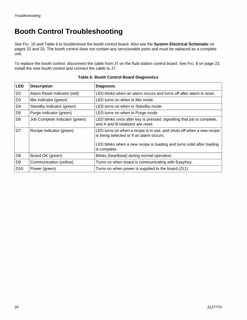
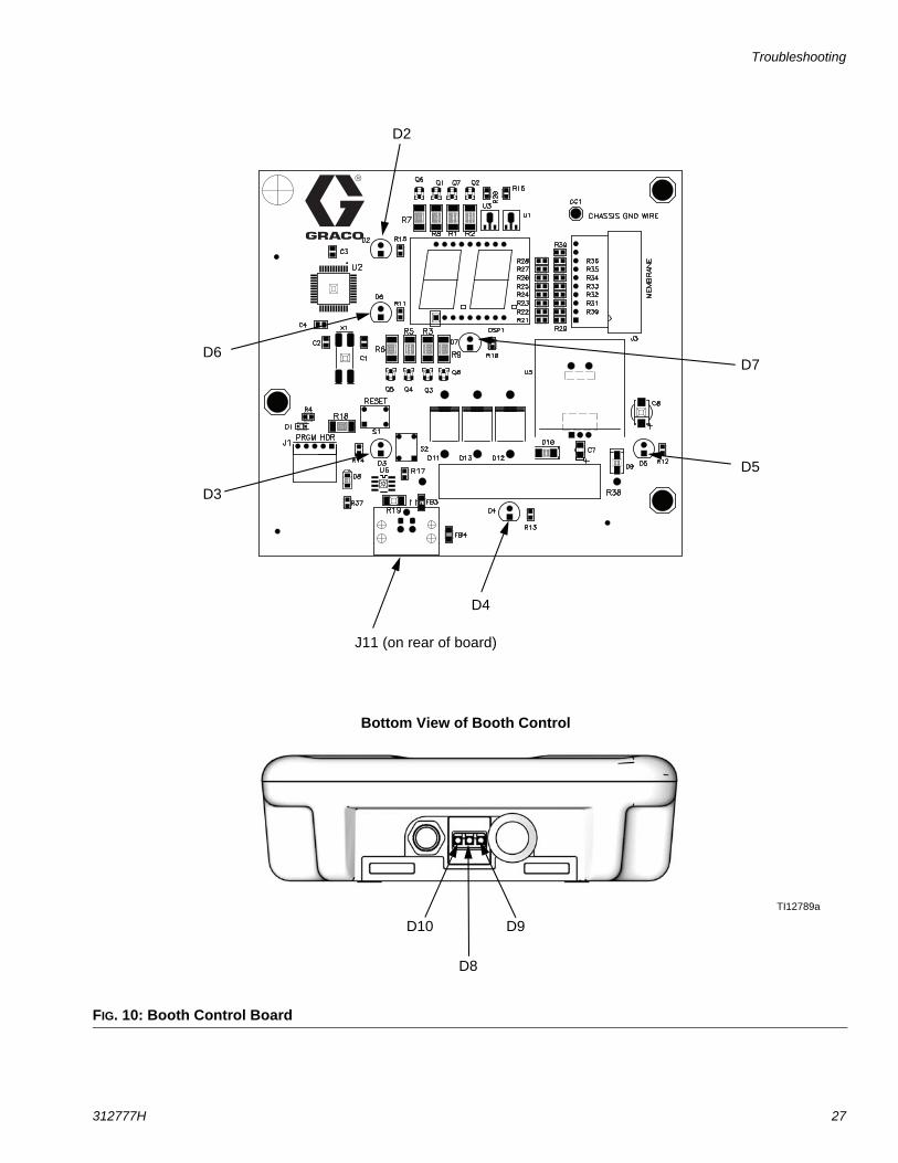
Booth Control TroubleshootingSee FIG. 10 and Table 6 to troubleshoot the booth control board. Also see the System Electrical Schematic on pages 32 and 33. The booth control does not contain any servciceable parts and must be replaced as a complete unit.
To replace the booth control, disconnect the cable from J7 on the fluid station control board. See FIG. 8 on page 23. Install the new booth control and connect the cable to J7.
Table 6: Booth Control Board Diagnostics
LED Description Diagnosis
D2 Alarm Reset Indicator (red) LED blinks when an alarm occurs and turns off after alarm is reset.
D3 Mix Indicator (green) LED turns on when in Mix mode.
D4 Standby Indicator (green) LED turns on when in Standby mode.
D5 Purge Indicator (green) LED turns on when in Purge mode.
D6 Job Complete Indicator (green) LED blinks once after key is pressed, signalling that job is complete, and A and B totalizers are reset.
D7 Recipe Indicator (green) LED turns on when a recipe is in use, and shuts off when a new recipe is being selected or if an alarm occurs.
LED blinks when a new recipe is loading and turns solid after loading is complete.
D8 Board OK (green) Blinks (heartbeat) during normal operation.
D9 Communication (yellow) Turns on when board is communicating with EasyKey.
D10 Power (green) Turns on when power is supplied to the board (J11).
Troubleshooting
312777H 27
FIG. 10: Booth Control Board
D7D6
D3
D4
D5
D2
J11 (on rear of board)
TI12789a
Bottom View of Booth Control
D8
D9D10
Troubleshooting
28 312777H
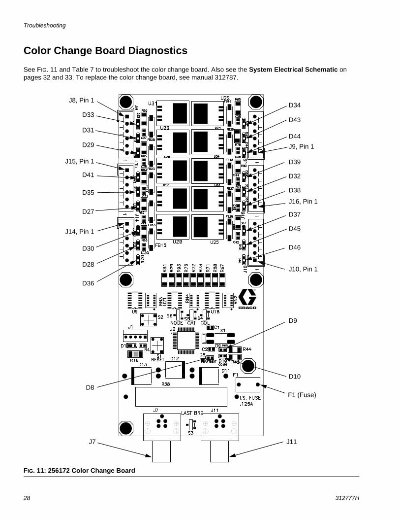
Color Change Board Diagnostics
See FIG. 11 and Table 7 to troubleshoot the color change board. Also see the System Electrical Schematic on pages 32 and 33. To replace the color change board, see manual 312787.
FIG. 11: 256172 Color Change Board
J8, Pin 1
J9, Pin 1
J14, Pin 1
J15, Pin 1
D45
D36
D46
D37
D44
D8
D29
D41
D35
D31
D9
J16, Pin 1
J10, Pin 1
D34
D43
D39
D32
D38
D28
D30
D27
D33
D10
J7 J11
F1 (Fuse)
Troubleshooting
312777H 29
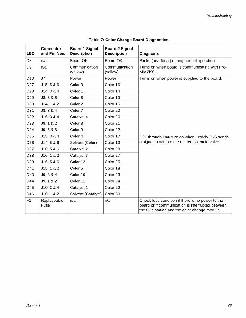
Table 7: Color Change Board Diagnostics
LED Connector and Pin Nos.
Board 1 Signal Description
Board 2 Signal Description Diagnosis
D8 n/a Board OK Board OK Blinks (heartbeat) during normal operation.
D9 n/a Communication (yellow)
Communication (yellow)
Turns on when board is communicating with Pro-Mix 2KS.
D10 J7 Power Power Turns on when power is supplied to the board.
D27 J15, 5 & 6 Color 3 Color 16
D27 through D46 turn on when ProMix 2KS sends a signal to actuate the related solenoid valve.
D28 J14, 3 & 4 Color 1 Color 14
D29 J8, 5 & 6 Color 6 Color 19
D30 J14, 1 & 2 Color 2 Color 15
D31 J8, 3 & 4 Color 7 Color 20
D32 J16, 3 & 4 Catalyst 4 Color 26
D33 J8, 1 & 2 Color 8 Color 21
D34 J9, 5 & 6 Color 9 Color 22
D35 J15, 3 & 4 Color 4 Color 17
D36 J14, 5 & 6 Solvent (Color) Color 13
D37 J10, 5 & 6 Catalyst 2 Color 28
D38 J16, 1 & 2 Catalyst 3 Color 27
D39 J16, 5 & 6 Color 12 Color 25
D41 J15, 1 & 2 Color 5 Color 18
D43 J9, 3 & 4 Color 10 Color 23
D44 J9, 1 & 2 Color 11 Color 24
D45 J10, 3 & 4 Catalyst 1 Color 29
D46 J10, 1 & 2 Solvent (Catalyst) Color 30
F1 Replaceable Fuse
n/a n/a Check fuse condition if there is no power to the board or if communication is interrupted between the fluid station and the color change module.
Schematic Diagrams
30 312777H
Schematic Diagrams
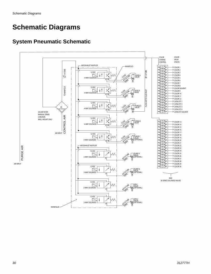
System Pneumatic Schematic
3/8 AIR FILTERMANUAL DRAIN5 MICRONWALL MOUNT ONLY
FLUS
H AI
R TO
FLUI
D IN
LET
1/4 T
UBE
TO M
ANIFO
LD
1/4 T
UBE
4-WAY SOLENOID
12 VDC
PURGE AVALVE
DUMP AVALVE(OPTIONAL)
4-WAY SOLENOID
12 VDC
3-WAY SOLENOID
12 VDC
3-WAY SOLENOID
12 VDC
MANIFOLDAIR EXHAUST MUFFLER
OPEN
CLOSE
OPEN5/32 TUBE
5/32 TUBE
PURGE BVALVE
4-WAY SOLENOID
12 VDC
CLOSE
OPEN5/32 TUBE
DUMP BVALVE(OPTIONAL)
4-WAY SOLENOID
12 VDC
OPEN5/32 TUBE
A B
A B
A B
A B
A
A
DOSE AVALVECLOSE
OPEN5/32 TUBE
DOSE BVALVECLOSE
OPEN5/32 TUBE
3-WAY SOLENOID
12 VDCGFB 1VALVE(OPTIONAL)5/32 TUBE
A
COLOR 1COLOR 2COLOR 3COLOR 4COLOR 5COLOR 6COLOR 7COLOR 8COLOR SOLVENTCOLOR 9COLOR 10COLOR 11COLOR 12CATALYST 1CATALYST 2CATALYST 3CATALYST 4CATALYST SOLVENT
COLORCHANGECONTROL
COLORVALVESTACKS
MAC36 SERIES SOLENOID VALVES
05
COLOR 13COLOR 14COLOR 15COLOR 16COLOR 17COLOR 18COLOR 19COLOR 20COLOR 21COLOR 22COLOR 23COLOR 24COLOR 25COLOR 26COLOR 27COLOR 28COLOR 29COLOR 30
PURGE CVALVE(OPTIONAL)4-WAY SOLENOID
12 VDC
CLOSE
OPEN5/32 TUBE
A B
AIR EXHAUST MUFFLER
3-WAY SOLENOID
12 VDCGFB 2VALVE(OPTIONAL)
OPEN5/32 TUBE
A
OPEN
MANIFOLD
AIR INPUT
AIR INPUT
PU
RG
E A
IR
CO
NT
RO
L A
IR
Schematic Diagrams
312777H 31
EasyKey Electrical Schematic
J9
4 3 2 1
GR
EE
N/B
LA
CK
/WH
ITE
22 A
WG
RE
D/B
LA
CK
/WH
ITE
22 A
WG
B
LA
CK
18 A
WG
RE
D 1
8 A
WG
- +
ALA
RM
- - + DC
OK
P
OW
ER
SU
PP
LY
CO
MM
ON
24
VD
C+
BA
RR
IER
BO
AR
D
J4-3
J4-2
J4-1
J1-5
J1-4
J1-3
J1-2
J1-1
TE
RM
INA
L B
LO
CK
SP
OW
ER
RO
CK
ER
SW
ITC
H
L L N N
24
VD
C+
OU
TP
UT
HIG
HV
OLTA
GE
IN
J4
24
VD
C+
IN
J1
GN
D L1
N
J5-3
J5-2
J5-1
J5
IS P
OW
ER
12 V
DC
DIS
PLA
Y B
OA
RD
BLA
CK
18 A
WG
RE
D 1
8 A
WG
GR
N/Y
EL 1
6 A
WG
R
ED
16 A
WG
B
RO
WN
16 A
WG
+1
2 V
DC
I/S
(W
HIT
E)
CO
MM
ON
(B
LA
CK
)
SH
IEL
D/G
RN
D
RJ4
5R
J4
5
P1
RJ4
5R
J4
5 B
UL
KH
EA
D
DIS
PLA
Y B
OA
RD
+ + + +
- - - -
GN
D L1
N
L1
N
LIN
E F
ILT
ER
R
ED
16 A
WG
B
RO
WN
16 A
WG
2 5
1 4
R
ED
16 A
WG
BR
OW
N 1
6 A
WG
GN
D L
UG
RE
D 1
8 A
WG
BLA
CK
18 A
WG
UN
US
ED
UN
US
ED
UN
US
ED
UN
US
ED
UN
US
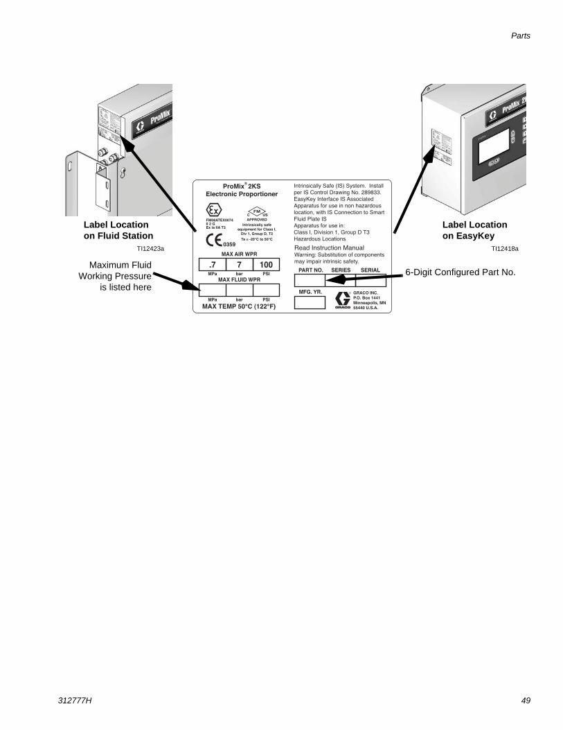
ED
Schematic Diagrams
32 312777H
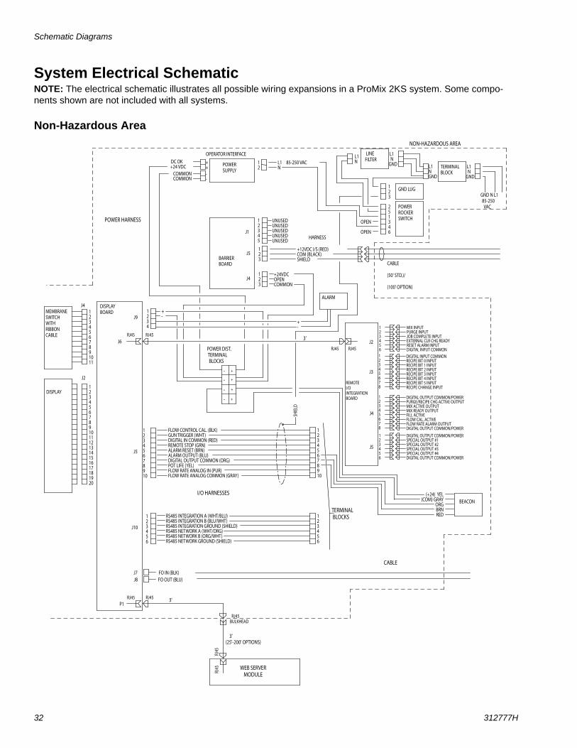
System Electrical SchematicNOTE: The electrical schematic illustrates all possible wiring expansions in a ProMix 2KS system. Some compo-nents shown are not included with all systems.
Non-Hazardous Area
BARRIERBOARD
OPERATOR INTERFACE
12
L1N
85-250 VAC
GND N L1
85-250 VAC
123
J5+12VDC I/S (RED)COM (BLACK)SHIELD
123
J4+24VDCOPENCOMMON
DISPLAYBOARD
NON-HAZARDOUS AREA
1234
J9 +-
FO IN (BLK)FO OUT (BLU)
1234567891011
J4
1234567891011121314151617181920
DISPLAY
MEMBRANESWITCHWITHRIBBONCABLE
CABLE
HARNESS
TERMINALBLOCK
123
GND LUG
251346
POWERROCKERSWITCH1
2345
J1
OPEN OPEN
ALARM
CABLE
(50' STD.)/
(100' OPTION)
123456
J10
12345678910
J5
J7J8
RJ45
MIX INPUTPURGE INPUTJOB COMPLETE INPUTEXTERNAL CLR CHG READYRESET ALARM INPUTDIGITAL INPUT COMMON
123456
RJ45
POWERSUPPLY
RS485 INTEGRATION A (WHT/BLU)RS485 INTEGRATION B (BLU/WHT)RS485 INTEGRATION GROUND (SHIELD)RS485 NETWORK A (WHT/ORG)RS485 NETWORK B (ORG/WHT)RS485 NETWORK GROUND (SHIELD)
FLOW CONTROL CAL. (BLK)GUN TRIGGER (WHT)DIGITAL IN COMMON (RED)REMOTE STOP (GRN)ALARM RESET (BRN)ALARM OUTPUT (BLU)DIGITAL OUTPUT COMMON (ORG)POT LIFE (YEL)FLOW RATE ANALOG IN (PUR)FLOW RATE ANALOG COMMON (GRAY)
12345678
DIGITAL INPUT COMMONRECIPE BIT 0 INPUTRECIPE BIT 1 INPUTRECIPE BIT 2 INPUTRECIPE BIT 3 INPUTRECIPE BIT 4 INPUTRECIPE BIT 5 INPUTRECIPE CHANGE INPUT
12345678
DIGITAL OUTPUT COMMON/POWERPURGE/RECIPE CHG ACTIVE OUTPUTMIX ACTIVE OUTPUTMIX READY OUTPUTFILL ACTIVEFLOW CAL. ACTIVEFLOW RATE ALARM OUTPUTDIGITAL OUTPUT COMMON/POWER
DIGITAL OUTPUT COMMON/POWERSPECIAL OUTPUT #1SPECIAL OUTPUT #2SPECIAL OUTPUT #3SPECIAL OUTPUT #4DIGITAL OUTPUT COMMON/POWER
123456
REMOTEI/O INTEGRATIONBOARD
J2
J3
J4
J5
RJ45RJ45P1
J6
WEB SERVERMODULE
RJ45
RJ45
RJ45RJ45
TERMINAL BLOCKS
++--
DC OK
COMMON
+24 VDCCOMMON
+-
J2
SHIE
LD
+
+
+
+
-
-
-
-
POWER DIST. TERMINAL BLOCKS
3'
3'(25'-200' OPTIONS)
12345678910
123456
RJ45BULKHEAD
3'
I/O HARNESSES
POWER HARNESS
BEACON(+24) YEL
(COM) GRAY ORG BRN RED
UNUSEDUNUSEDUNUSEDUNUSEDUNUSED
L1 NGND
L1N
LINEFILTER
L1NGND
L1 NGND
Schematic Diagrams
312777H 33
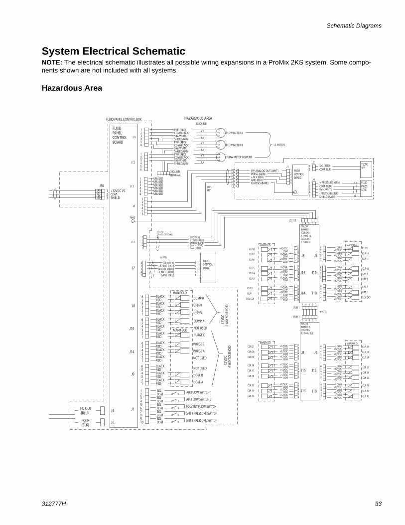
System Electrical SchematicNOTE: The electrical schematic illustrates all possible wiring expansions in a ProMix 2KS system. Some compo-nents shown are not included with all systems.
Hazardous Area
HAZARDOUS AREA
+12VDC I/SCOMSHIELD
J10123
123456
J3
PWR (RED)COM (BLACK)SIG (WHITE)SHIELD/GRNPWR (RED)COM (BLACK)SIG (WHITE)SHIELD/GRNPWR (RED)COM (BLACK)SIG (WHITE)SHIELD/GRN
FLUIDPANELCONTROLBOARD
FLUID PANEL CONTROL BOX
FLOW METER A
FLOW METER B
123456
J5
12345
FLOWCONTROLBOARD
654321
J9
BLACKREDBLACKREDBLACKRED
MANIFOLD
NOT USED
DOSE B
DOSE A
12345678910
J1
SIGCOMSIGCOMSIGCOMSIGCOMSIGCOM
AIR FLOW SWITCH 1
FO OUT (BLU)
FO IN(BLK)
12
J1J2
3X CABLE
FLOW METER SOLVENT
12345
TECNOV/P
FLUIDPRESS.SENS.
J4
SIG (RED)COM (BLK)
+ PRESSURE (GRN)COM (RED)EX+ (WHT)- PRESSURE (BLK)SHIELD (BARE)
32541
J11
GRD (BLK)+12VDC (RED)SHIELD (BARE)CAN H (WHT)CAN L (BLU)
J7/J111 4 5 2 3
COLORBOARD 1(COLORS1 THRU 12, CATALYST1 THRU 4)
CLR 9
CLR 10
CLR 11
1 4 5 2 3
V/P ANALOG OUT (WHT)PRESS. (GRN)+12 V (RED)GND (BLK)CHASSIS (BARE)
MH2
(10')/(40')
6' STD.
6' STD.(3'-100' OPTIONS)
I.S. METERS
32541
GRD (BLK)+12VDC (RED)SHIELD (BARE)CAN H (WHT)CAN L (BLU)
32541
BOOTHCONTROLBOARD
654321
J14
BLACKREDBLACKREDBLACKRED
AIR FLOW SWITCH 2
SOLVENT FLOW SWITCH
GFB 1 PRESSURE SWITCH
GFB 2 PRESSURE SWITCH
PURGE B
PURGE A
NOT USED
654321
BLACKREDBLACKREDBLACKRED
DUMP A
NOT USED
PURGE C
MANIFOLD654321
BLACKREDBLACKREDBLACKRED
DUMP B
GFB #1
GFB #2
12
VDC
3-WAY
SOLENO
ID
J15
J8
12
VDC
4-WAY
SOLENO
ID
123456
J12
J13
123456
UNUSEDUNUSEDUNUSEDUNUSEDUNUSEDUNUSED
GROUNDTERMINAL
50' STD.
123456
+12VDC COM
+12VDC COM
+12VDC COM
MANIFOLD
123456
+12VDC COM
+12VDC COM
+12VDC COM
123456
+12VDC COM
+12VDC COM
+12VDC COM
1 4 5 2 3
MANIFOLD654321
COM+12VDC
COM+12VDC
COM+12VDC
COM
+12VDC COM
+12VDC COM
+12VDC
COM+12VDC
COM+12VDC
COM+12VDC
654321
654321
CLR 12
CAT 4
CAT 3
CAT 2
CAT 1
SOL CAT
CLR 8
CLR 7
CLR 6
CLR 5
CLR 4
CLR 3
CLR 2
CLR 1
SOL CLR
COLORBOARD 2(COLORS13 THRU 30)
CLR 22
CLR 23
CLR 24
123456
+12VDC COM
+12VDC COM
+12VDC COM
MANIFOLD
123456
+12VDC COM
+12VDC COM
+12VDC COM
123456
+12VDC COM
+12VDC COM
+12VDC COM
MANIFOLD654321
COM+12VDC
COM+12VDC
COM+12VDC
COM
+12VDC COM
+12VDC COM
+12VDC
COM+12VDC
COM+12VDC
COM+12VDC
654321
654321
CLR 25
CLR 26
CLR 27
CLR 28
CLR 29
CLR 30
CLR 21
CLR 20
CLR 19
CLR 18
CLR 17
CLR 16
CLR 15
CLR 14
CLR 13
J8
J8
J15
J15
J14
J14
J9
J9
J16
J10
J10
J16
J4
J6
J7
J7/J11
J7/J11
Schematic Diagrams
34 312777H
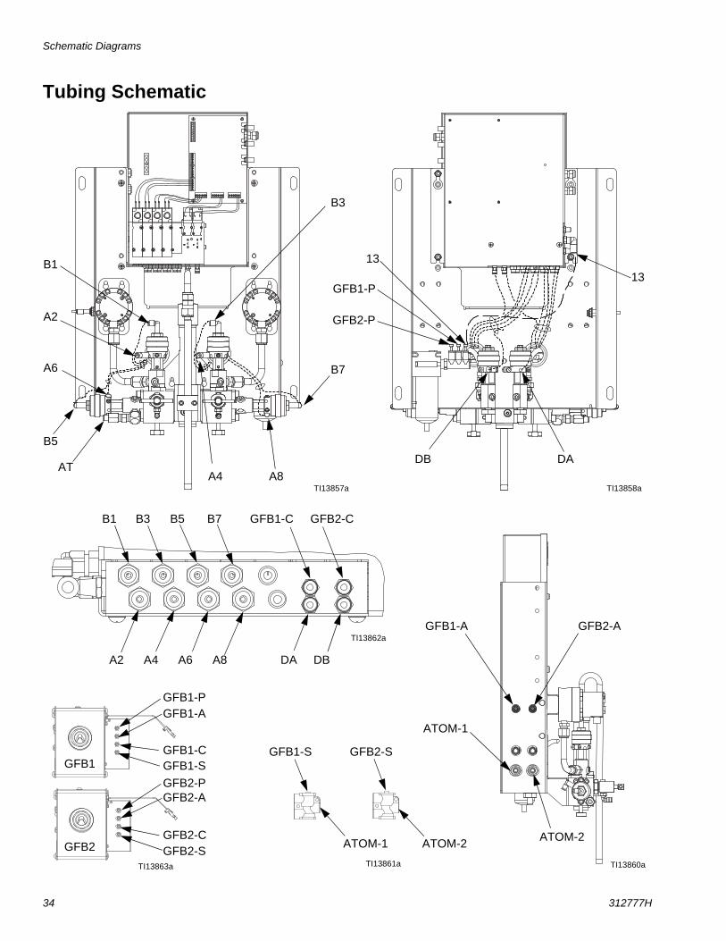
Tubing Schematic
TI13862a
TI13857a TI13858a
A2
A4
A6
A8
A2 A4 A6 A8
B1 B3 B5 B7
B1
B3
B5
B7
13
13
DA DB
DADB
TI13861a TI13860aTI13863a
GFB1-C GFB2-C
GFB1-S
GFB2-S
GFB1-P
GFB2-P
GFB1-A
GFB2-A
ATOM-1
ATOM-2ATOM-1 ATOM-2
GFB1-C
GFB2-C
GFB1-S GFB2-S
GFB1-P
GFB2-P
GFB1-A GFB2-A
GFB1
GFB2
AT
Schematic Diagrams
312777H 35
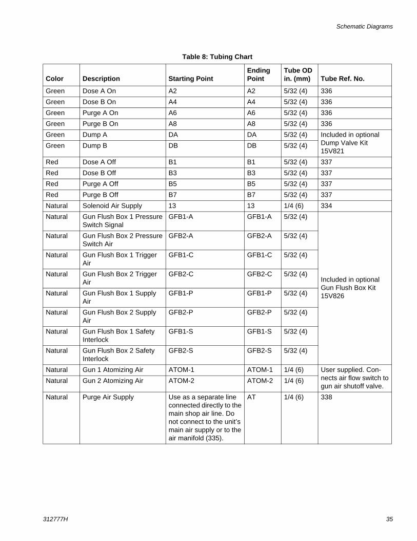
Table 8: Tubing Chart
Color Description Starting PointEnding Point
Tube OD in. (mm) Tube Ref. No.
Green Dose A On A2 A2 5/32 (4) 336
Green Dose B On A4 A4 5/32 (4) 336
Green Purge A On A6 A6 5/32 (4) 336
Green Purge B On A8 A8 5/32 (4) 336
Green Dump A DA DA 5/32 (4) Included in optional Dump Valve Kit 15V821
Green Dump B DB DB 5/32 (4)
Red Dose A Off B1 B1 5/32 (4) 337
Red Dose B Off B3 B3 5/32 (4) 337
Red Purge A Off B5 B5 5/32 (4) 337
Red Purge B Off B7 B7 5/32 (4) 337
Natural Solenoid Air Supply 13 13 1/4 (6) 334
Natural Gun Flush Box 1 Pressure Switch Signal
GFB1-A GFB1-A 5/32 (4)
Included in optional Gun Flush Box Kit 15V826
Natural Gun Flush Box 2 Pressure Switch Air
GFB2-A GFB2-A 5/32 (4)
Natural Gun Flush Box 1 Trigger Air
GFB1-C GFB1-C 5/32 (4)
Natural Gun Flush Box 2 Trigger Air
GFB2-C GFB2-C 5/32 (4)
Natural Gun Flush Box 1 Supply Air
GFB1-P GFB1-P 5/32 (4)
Natural Gun Flush Box 2 Supply Air
GFB2-P GFB2-P 5/32 (4)
Natural Gun Flush Box 1 Safety Interlock
GFB1-S GFB1-S 5/32 (4)
Natural Gun Flush Box 2 Safety Interlock
GFB2-S GFB2-S 5/32 (4)
Natural Gun 1 Atomizing Air ATOM-1 ATOM-1 1/4 (6) User supplied. Con-nects air flow switch to gun air shutoff valve.
Natural Gun 2 Atomizing Air ATOM-2 ATOM-2 1/4 (6)
Natural Purge Air Supply Use as a separate line connected directly to the main shop air line. Do not connect to the unit’s main air supply or to the air manifold (335).
AT 1/4 (6) 338
Service
36 312777H
Service
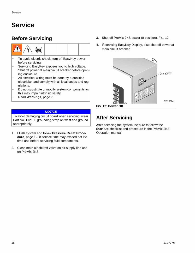
Before Servicing
1. Flush system and follow Pressure Relief Proce-dure, page 12, if service time may exceed pot life time and before servicing fluid components.
2. Close main air shutoff valve on air supply line and on ProMix 2KS.
3. Shut off ProMix 2KS power (0 position). FIG. 12.
4. If servicing EasyKey Display, also shut off power at main circuit breaker.
After ServicingAfter servicing the system, be sure to follow the Start Up checklist and procedure in the ProMix 2KS Operation manual.
• To avoid electric shock, turn off EasyKey power before servicing.
• Servicing EasyKey exposes you to high voltage. Shut off power at main circuit breaker before open-ing enclosure.
• All electrical wiring must be done by a qualified electrician and comply with all local codes and reg-ulations.
• Do not substitute or modify system components as this may impair intrinsic safety.
• Read Warnings, page 7.
NOTICETo avoid damaging circuit board when servicing, wear Part No. 112190 grounding strap on wrist and ground appropriately.
FIG. 12: Power Off
0 = OFF
TI12657a
Service
312777H 37
Servicing EasyKey
Updating SoftwareTo update software, upload new software from your PC using the basic web interface. See manual 313386.
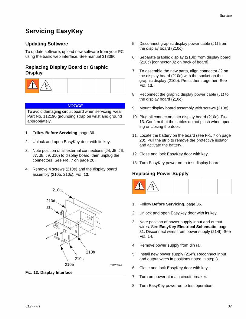
Replacing Display Board or Graphic Display
1. Follow Before Servicing, page 36.
2. Unlock and open EasyKey door with its key.
3. Note position of all external connections (J4, J5, J6, J7, J8, J9, J10) to display board, then unplug the connectors. See FIG. 7 on page 20.
4. Remove 4 screws (210e) and the display board assembly (210b, 210c). FIG. 13.
5. Disconnect graphic display power cable (J1) from the display board (210c).
6. Separate graphic display (210b) from display board (210c) [connector J2 on back of board].
7. To assemble the new parts, align connector J2 on the display board (210c) with the socket on the graphic display (210b). Press them together. See FIG. 13.
8. Reconnect the graphic display power cable (J1) to the display board (210c).
9. Mount display board assembly with screws (210e).
10. Plug all connectors into display board (210c). FIG. 13. Confirm that the cables do not pinch when open-ing or closing the door.
11. Locate the battery on the board (see FIG. 7 on page 20). Pull the strip to remove the protective isolator and activate the battery.
12. Close and lock EasyKey door with key.
13. Turn EasyKey power on to test display board.
Replacing Power Supply
1. Follow Before Servicing, page 36.
2. Unlock and open EasyKey door with its key.
3. Note position of power supply input and output wires. See EasyKey Electrical Schematic, page 31. Disconnect wires from power supply (214f). See FIG. 14.
4. Remove power supply from din rail.
5. Install new power supply (214f). Reconnect input and output wires in positions noted in step 3.
6. Close and lock EasyKey door with key.
7. Turn on power at main circuit breaker.
8. Turn EasyKey power on to test operation.
NOTICETo avoid damaging circuit board when servicing, wear Part No. 112190 grounding strap on wrist and ground appropriately.
FIG. 13: Display Interface
210a
TI12554a210e210c
210d
210b
J1
Service
38 312777H
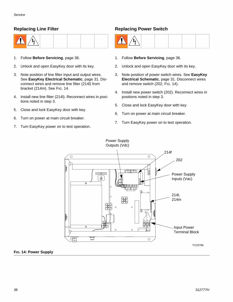
Replacing Line Filter
1. Follow Before Servicing, page 36.
2. Unlock and open EasyKey door with its key.
3. Note position of line filter input and output wires. See EasyKey Electrical Schematic, page 31. Dis-connect wires and remove line filter (214l) from bracket (214m). See FIG. 14.
4. Install new line filter (214l). Reconnect wires in posi-tions noted in step 3.
5. Close and lock EasyKey door with key.
6. Turn on power at main circuit breaker.
7. Turn EasyKey power on to test operation.
Replacing Power Switch
1. Follow Before Servicing, page 36.
2. Unlock and open EasyKey door with its key.
3. Note position of power switch wires. See EasyKey Electrical Schematic, page 31. Disconnect wires and remove switch (202, FIG. 14).
4. Install new power switch (202). Reconnect wires in positions noted in step 3.
5. Close and lock EasyKey door with key.
6. Turn on power at main circuit breaker.
7. Turn EasyKey power on to test operation.
FIG. 14: Power Supply
TI12578b
214f
Power Supply Outputs (Vdc)
202
Power Supply Inputs (Vac)
214l, 214m
Input Power Terminal Block
Service
312777H 39
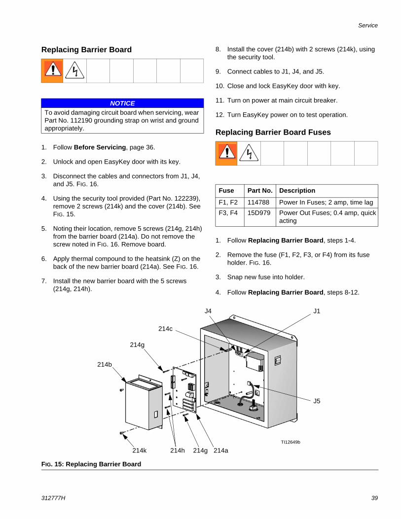
Replacing Barrier Board
1. Follow Before Servicing, page 36.
2. Unlock and open EasyKey door with its key.
3. Disconnect the cables and connectors from J1, J4, and J5. FIG. 16.
4. Using the security tool provided (Part No. 122239), remove 2 screws (214k) and the cover (214b). See FIG. 15.
5. Noting their location, remove 5 screws (214g, 214h) from the barrier board (214a). Do not remove the screw noted in FIG. 16. Remove board.
6. Apply thermal compound to the heatsink (Z) on the back of the new barrier board (214a). See FIG. 16.
7. Install the new barrier board with the 5 screws (214g, 214h).
8. Install the cover (214b) with 2 screws (214k), using the security tool.
9. Connect cables to J1, J4, and J5.
10. Close and lock EasyKey door with key.
11. Turn on power at main circuit breaker.
12. Turn EasyKey power on to test operation.
Replacing Barrier Board Fuses
1. Follow Replacing Barrier Board, steps 1-4.
2. Remove the fuse (F1, F2, F3, or F4) from its fuse holder. FIG. 16.
3. Snap new fuse into holder.
4. Follow Replacing Barrier Board, steps 8-12.
NOTICETo avoid damaging circuit board when servicing, wear Part No. 112190 grounding strap on wrist and ground appropriately.
Fuse Part No. Description
F1, F2 114788 Power In Fuses; 2 amp, time lag
F3, F4 15D979 Power Out Fuses; 0.4 amp, quick acting
FIG. 15: Replacing Barrier Board
TI12649b
214c
214g 214a214k
214b
214h
214g
J1J4
J5
Service
40 312777H
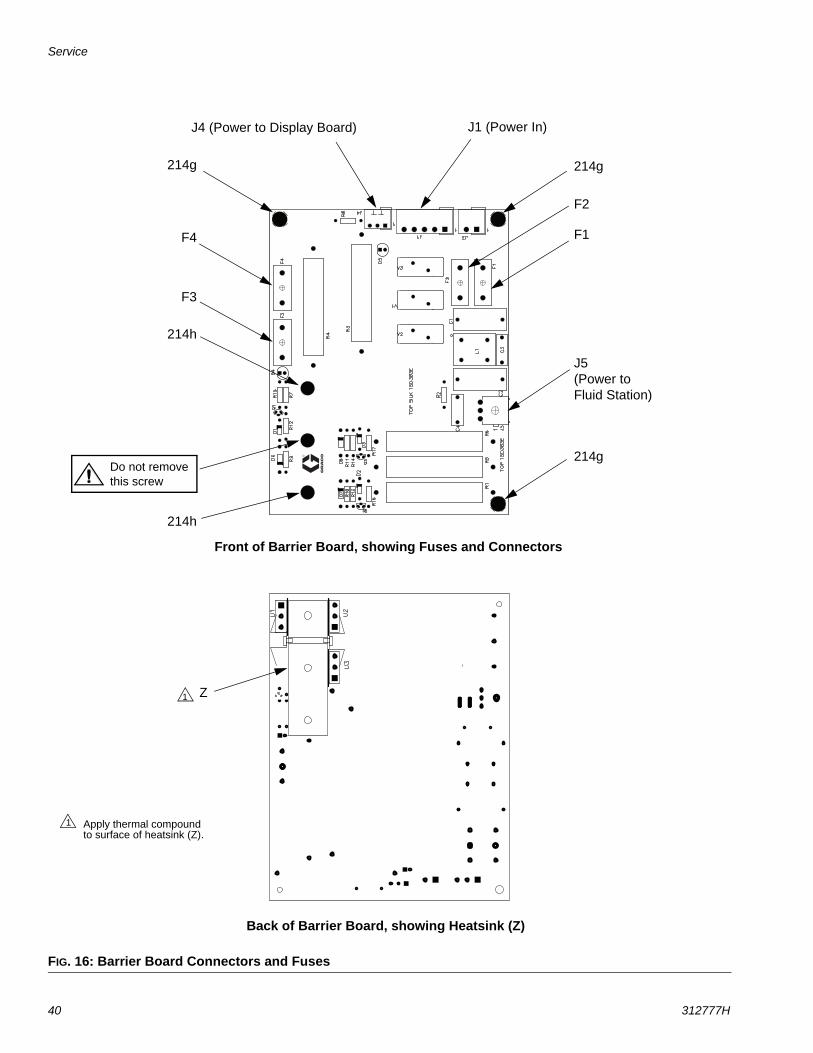
FIG. 16: Barrier Board Connectors and Fuses
Do not remove this screw
J1 (Power In)J4 (Power to Display Board)
J5(Power to Fluid Station)
F1
F2
F3
F4
214h
214h
214g
214g
214g
Back of Barrier Board, showing Heatsink (Z)
Z1
Front of Barrier Board, showing Fuses and Connectors
Apply thermal compound to surface of heatsink (Z).
1
Service
312777H 41
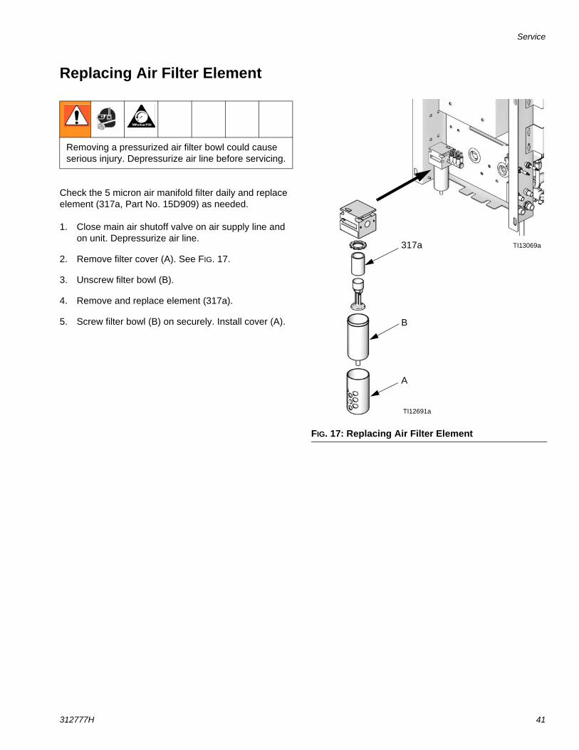
Replacing Air Filter Element
Check the 5 micron air manifold filter daily and replace element (317a, Part No. 15D909) as needed.
1. Close main air shutoff valve on air supply line and on unit. Depressurize air line.
2. Remove filter cover (A). See FIG. 17.
3. Unscrew filter bowl (B).
4. Remove and replace element (317a).
5. Screw filter bowl (B) on securely. Install cover (A).
Removing a pressurized air filter bowl could cause serious injury. Depressurize air line before servicing.
FIG. 17: Replacing Air Filter Element
TI12691a
317a
A
B
TI13069a
Service
42 312777H
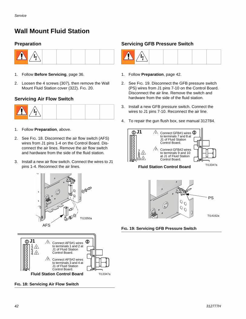
Wall Mount Fluid Station
Preparation
1. Follow Before Servicing, page 36.
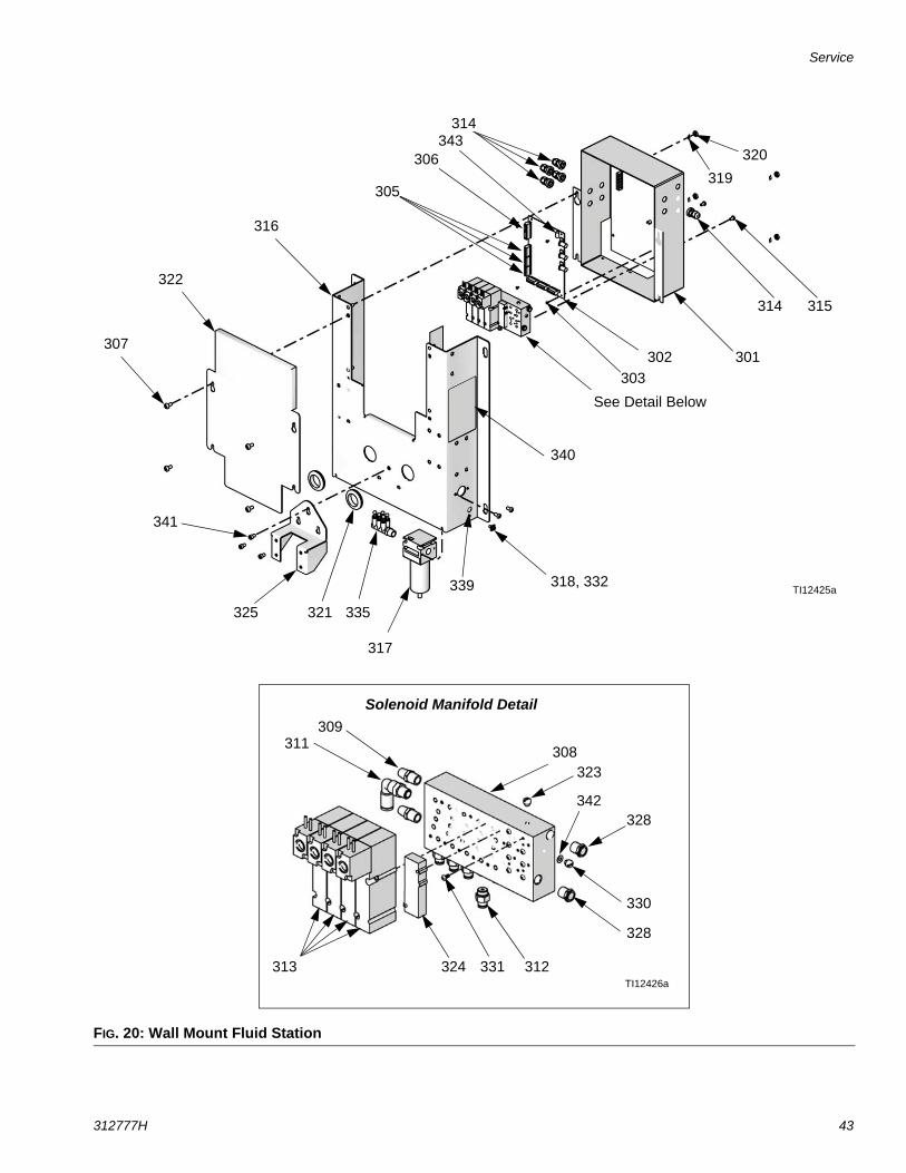
2. Loosen the 4 screws (307), then remove the Wall Mount Fluid Station cover (322). FIG. 20.
Servicing Air Flow Switch
1. Follow Preparation, above.
2. See FIG. 18. Disconnect the air flow switch (AFS) wires from J1 pins 1-4 on the Control Board. Dis-connect the air lines. Remove the air flow switch and hardware from the side of the fluid station.
3. Install a new air flow switch. Connect the wires to J1 pins 1-4. Reconnect the air lines.
Servicing GFB Pressure Switch
1. Follow Preparation, page 42.
2. See FIG. 19. Disconnect the GFB pressure switch (PS) wires from J1 pins 7-10 on the Control Board. Disconnect the air line. Remove the switch and hardware from the side of the fluid station.
3. Install a new GFB pressure switch. Connect the wires to J1 pins 7-10. Reconnect the air line.
4. To repair the gun flush box, see manual 312784.
FIG. 18: Servicing Air Flow Switch
TI13347a
AFS
TI13350a
1
2
J1
Fluid Station Control Board
Connect AFS#1 wires to terminals 1 and 2 at J1 of Fluid Station Control Board.
Connect AFS#2 wires to terminals 3 and 4 at J1 of Fluid Station Control Board.
1
2
1234
FIG. 19: Servicing GFB Pressure Switch
TI13347a
PS
TI14162a
1
2
J1
Fluid Station Control Board
Connect GFB#1 wires to terminals 7 and 8 at J1 of Fluid Station Control Board.
Connect GFB#2 wires to terminals 9 and 10 at J1 of Fluid Station Control Board.
1
2789
10
Service
312777H 43
FIG. 20: Wall Mount Fluid Station
331
301
323
315314
313
316
321
311
302
322
303
319
309
308
307
305
306
312
320
324
328
330
335
339
340
314
See Detail Below
318, 332
328
TI12425a
TI12426a
Solenoid Manifold Detail
317
341
325
342
343
Service
44 312777H
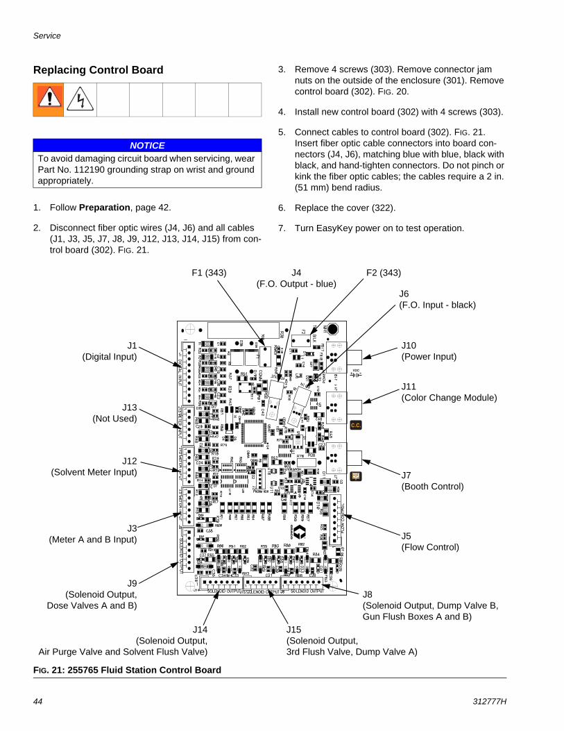
Replacing Control Board
1. Follow Preparation, page 42.
2. Disconnect fiber optic wires (J4, J6) and all cables (J1, J3, J5, J7, J8, J9, J12, J13, J14, J15) from con-trol board (302). FIG. 21.
3. Remove 4 screws (303). Remove connector jam nuts on the outside of the enclosure (301). Remove control board (302). FIG. 20.
4. Install new control board (302) with 4 screws (303).
5. Connect cables to control board (302). FIG. 21. Insert fiber optic cable connectors into board con-nectors (J4, J6), matching blue with blue, black with black, and hand-tighten connectors. Do not pinch or kink the fiber optic cables; the cables require a 2 in. (51 mm) bend radius.
6. Replace the cover (322).
7. Turn EasyKey power on to test operation.
NOTICETo avoid damaging circuit board when servicing, wear Part No. 112190 grounding strap on wrist and ground appropriately.
FIG. 21: 255765 Fluid Station Control Board
J6(F.O. Input - black)
J4(F.O. Output - blue)
J10(Power Input)
J5(Flow Control)
J11(Color Change Module)
J7(Booth Control)
J15(Solenoid Output,3rd Flush Valve, Dump Valve A)
J8(Solenoid Output, Dump Valve B, Gun Flush Boxes A and B)
J14(Solenoid Output,
Air Purge Valve and Solvent Flush Valve)
J1(Digital Input)
J9(Solenoid Output,
Dose Valves A and B)
J3(Meter A and B Input)
J12(Solvent Meter Input)
J13(Not Used)
F2 (343)F1 (343)
Service
312777H 45
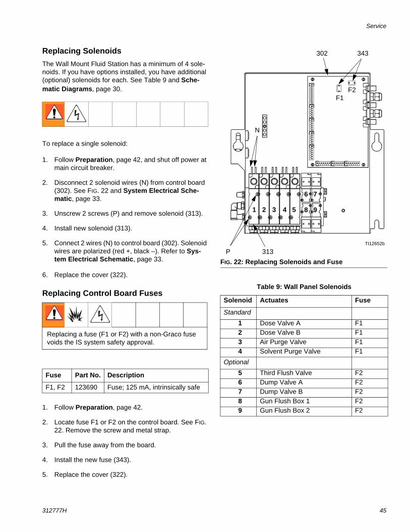
Replacing SolenoidsThe Wall Mount Fluid Station has a minimum of 4 sole-noids. If you have options installed, you have additional (optional) solenoids for each. See Table 9 and Sche-matic Diagrams, page 30.
To replace a single solenoid:
1. Follow Preparation, page 42, and shut off power at main circuit breaker.
2. Disconnect 2 solenoid wires (N) from control board (302). See FIG. 22 and System Electrical Sche-matic, page 33.
3. Unscrew 2 screws (P) and remove solenoid (313).
4. Install new solenoid (313).
5. Connect 2 wires (N) to control board (302). Solenoid wires are polarized (red +, black –). Refer to Sys-tem Electrical Schematic, page 33.
6. Replace the cover (322).
Replacing Control Board Fuses
1. Follow Preparation, page 42.
2. Locate fuse F1 or F2 on the control board. See FIG. 22. Remove the screw and metal strap.
3. Pull the fuse away from the board.
4. Install the new fuse (343).
5. Replace the cover (322).
Replacing a fuse (F1 or F2) with a non-Graco fuse voids the IS system safety approval.
Fuse Part No. Description
F1, F2 123690 Fuse; 125 mA, intrinsically safe
FIG. 22: Replacing Solenoids and Fuse
Table 9: Wall Panel Solenoids
Solenoid Actuates Fuse
Standard
1 Dose Valve A F12 Dose Valve B F13 Air Purge Valve F14 Solvent Purge Valve F1
Optional
5 Third Flush Valve F26 Dump Valve A F27 Dump Valve B F28 Gun Flush Box 1 F29 Gun Flush Box 2 F2
TI12652b
N
P 313
4321
302
7
85
6
9
343
F1F2
Service
46 312777H
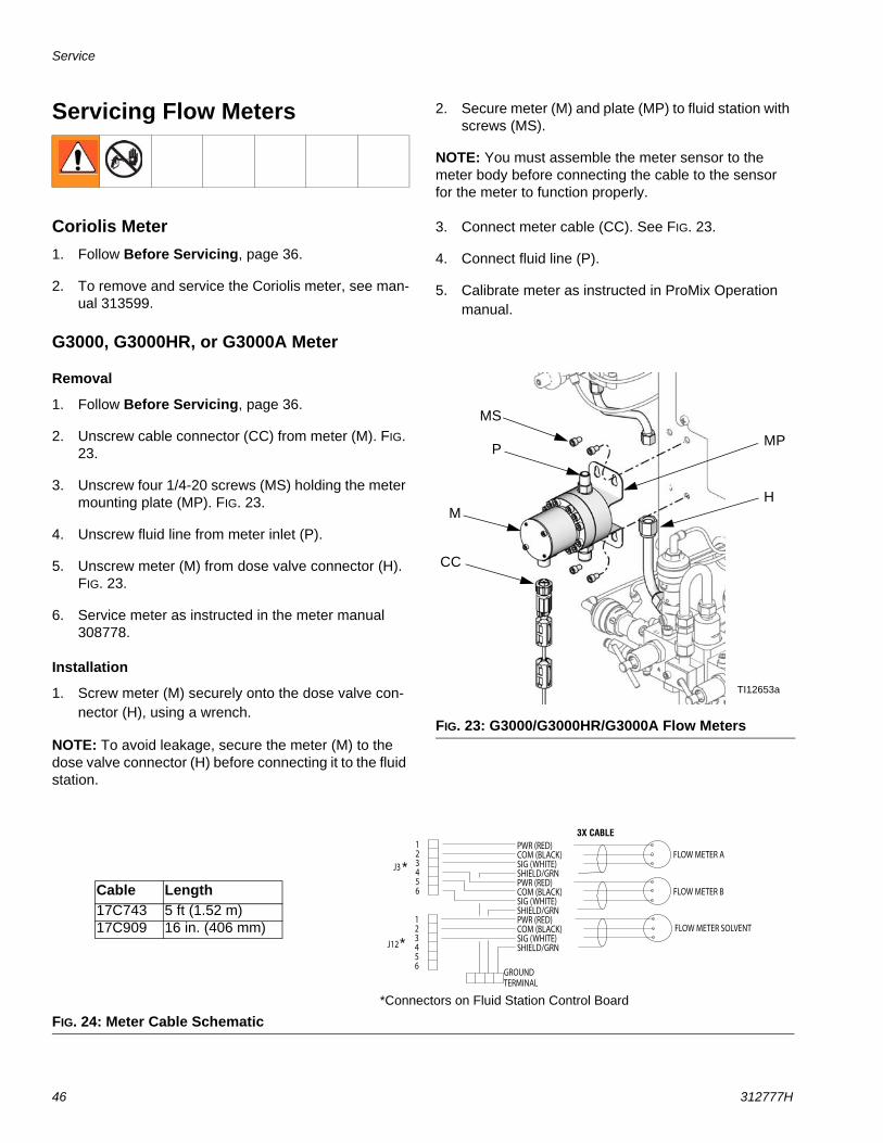
Servicing Flow Meters
Coriolis Meter1. Follow Before Servicing, page 36.
2. To remove and service the Coriolis meter, see man-ual 313599.
G3000, G3000HR, or G3000A Meter
Removal
1. Follow Before Servicing, page 36.
2. Unscrew cable connector (CC) from meter (M). FIG. 23.
3. Unscrew four 1/4-20 screws (MS) holding the meter mounting plate (MP). FIG. 23.
4. Unscrew fluid line from meter inlet (P).
5. Unscrew meter (M) from dose valve connector (H). FIG. 23.
6. Service meter as instructed in the meter manual 308778.
Installation
1. Screw meter (M) securely onto the dose valve con-nector (H), using a wrench.
NOTE: To avoid leakage, secure the meter (M) to the dose valve connector (H) before connecting it to the fluid station.
2. Secure meter (M) and plate (MP) to fluid station with screws (MS).
NOTE: You must assemble the meter sensor to the meter body before connecting the cable to the sensor for the meter to function properly.
3. Connect meter cable (CC). See FIG. 23.
4. Connect fluid line (P).
5. Calibrate meter as instructed in ProMix Operation manual.
FIG. 23: G3000/G3000HR/G3000A Flow Meters
TI12653a
CC
MH
MPP
MS
FIG. 24: Meter Cable Schematic
123456
J3
PWR (RED)COM (BLACK)SIG (WHITE)SHIELD/GRNPWR (RED)COM (BLACK)SIG (WHITE)SHIELD/GRNPWR (RED)COM (BLACK)SIG (WHITE)SHIELD/GRN
FLOW METER A
FLOW METER B
3X CABLE241799-801
FLOW METER SOLVENT123456
J12
GROUNDTERMINAL
*Connectors on Fluid Station Control Board
*
*
Cable Length17C743 5 ft (1.52 m)17C909 16 in. (406 mm)
3X CABLE
Service
312777H 47
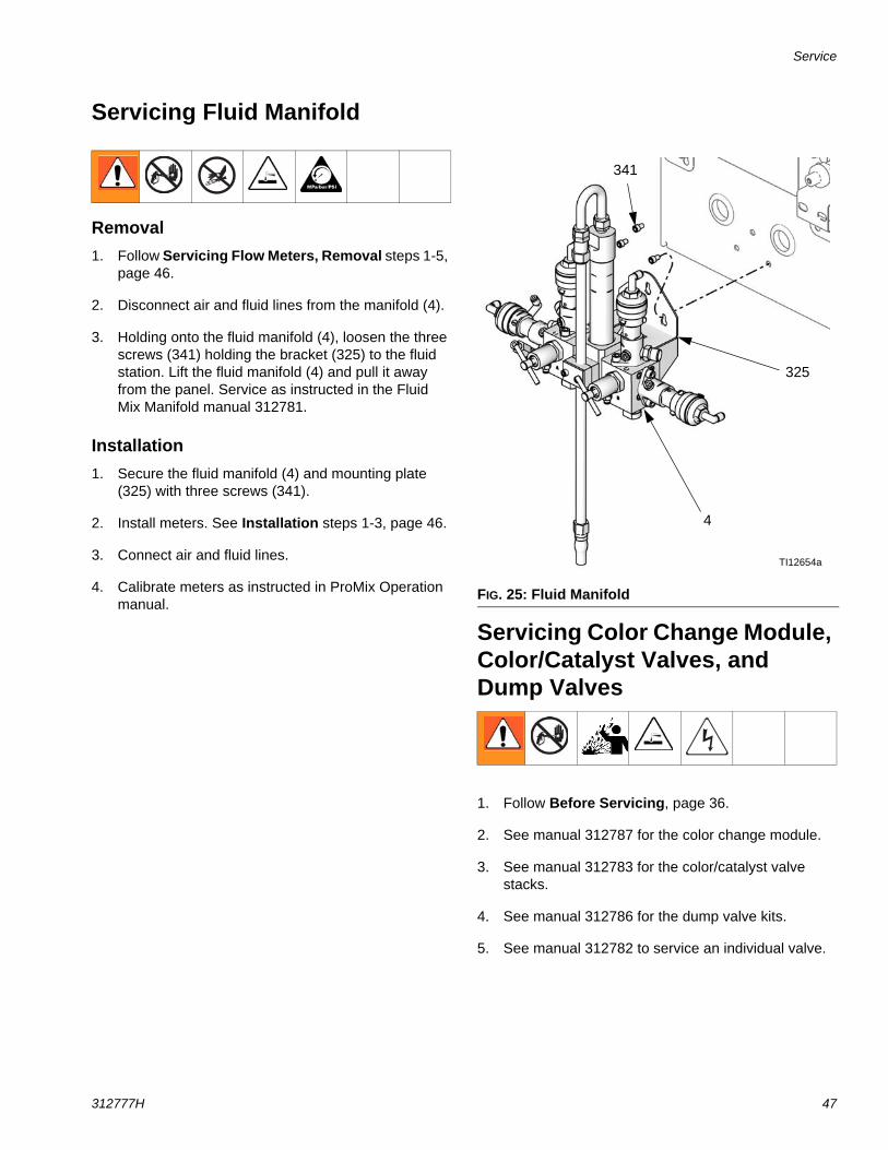
Servicing Fluid Manifold
Removal1. Follow Servicing Flow Meters, Removal steps 1-5,
page 46.
2. Disconnect air and fluid lines from the manifold (4).
3. Holding onto the fluid manifold (4), loosen the three screws (341) holding the bracket (325) to the fluid station. Lift the fluid manifold (4) and pull it away from the panel. Service as instructed in the Fluid Mix Manifold manual 312781.
Installation1. Secure the fluid manifold (4) and mounting plate
(325) with three screws (341).
2. Install meters. See Installation steps 1-3, page 46.
3. Connect air and fluid lines.
4. Calibrate meters as instructed in ProMix Operation manual.
Servicing Color Change Module, Color/Catalyst Valves, and Dump Valves
1. Follow Before Servicing, page 36.
2. See manual 312787 for the color change module.
3. See manual 312783 for the color/catalyst valve stacks.
4. See manual 312786 for the dump valve kits.
5. See manual 312782 to service an individual valve.
FIG. 25: Fluid Manifold
4
325
TI12654a
341
Parts
48 312777H
Parts
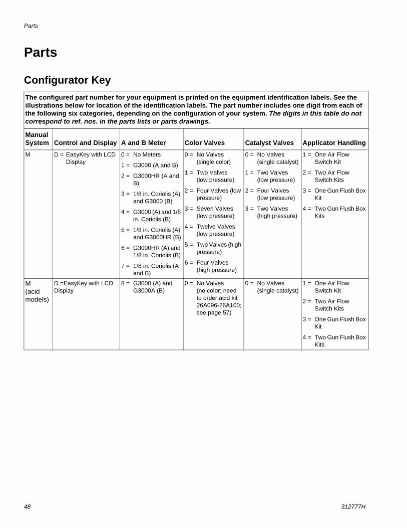
Configurator KeyThe configured part number for your equipment is printed on the equipment identification labels. See the illustrations below for location of the identification labels. The part number includes one digit from each of the following six categories, depending on the configuration of your system. The digits in this table do not correspond to ref. nos. in the parts lists or parts drawings.
Manual System Control and Display A and B Meter Color Valves Catalyst Valves Applicator Handling
M D = EasyKey with LCD Display
0 = No Meters
1 = G3000 (A and B)
2 = G3000HR (A and B)
3 = 1/8 in. Coriolis (A) and G3000 (B)
4 = G3000 (A) and 1/8 in. Coriolis (B)
5 = 1/8 in. Coriolis (A) and G3000HR (B)
6 = G3000HR (A) and 1/8 in. Coriolis (B)
7 = 1/8 in. Coriolis (A and B)
0 = No Valves (single color)
1 = Two Valves (low pressure)
2 = Four Valves (low pressure)
3 = Seven Valves (low pressure)
4 = Twelve Valves (low pressure)
5 = Two Valves (high pressure)
6 = Four Valves (high pressure)
0 = No Valves (single catalyst)
1 = Two Valves (low pressure)
2 = Four Valves (low pressure)
3 = Two Valves (high pressure)
1 = One Air Flow Switch Kit
2 = Two Air Flow Switch Kits
3 = One Gun Flush Box Kit
4 = Two Gun Flush Box Kits
M(acid models)
D =EasyKey with LCD Display
8 = G3000 (A) and G3000A (B)
0 = No Valves (no color; need to order acid kit 26A096-26A100; see page 57)
0 = No Valves (single catalyst)
1 = One Air Flow Switch Kit
2 = Two Air Flow Switch Kits
3 = One Gun Flush Box Kit
4 = Two Gun Flush Box Kits
Parts
312777H 49
�� � ��������� �
� � ��� ��������� �
� � ��� �
������ �����
��������� ������������������������������� ������������������������ ������
�����
���������� !"#��$�" ��%��#��$!�
������ &�'()���'�*
������ ��������������������������������������������� ����!���"#$#%%�&��'��������� �����(� ����(���������������������)�*������� ����+� �)��������� �����������,�����-������(����������������������+���.�����/+�0�������1%2�*������3� ����
$#��$+�"� ,+�-!!./�%0!$#-��( �++1
��2�13��/%�1�4
��56��'(#�&�'(
( �����7�������8�3������4
3��(��(� ���9���88���$$!�%� �+1��&&88�������
��3�:��
6-Digit Configured Part No.
Label Location on EasyKey
Label Location on Fluid Station
Maximum FluidWorking Pressure
is listed here
TI12418aTI12423a
Parts
50 312777H
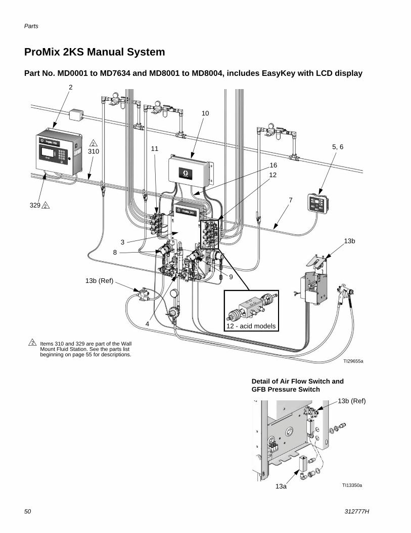
ProMix 2KS Manual System
Part No. MD0001 to MD7634 and MD8001 to MD8004, includes EasyKey with LCD display
TI29655a
Items 310 and 329 are part of the Wall Mount Fluid Station. See the parts list beginning on page 55 for descriptions.
2
2
10
2
310
329
11
38
4
1612
13b (Ref)
13b
9
2 5, 6
7
TI13350a
13b (Ref)
13a
Detail of Air Flow Switch and GFB Pressure Switch
12 - acid models
Parts
312777H 51
Ref. No.
Configured Digit (see page 48) or
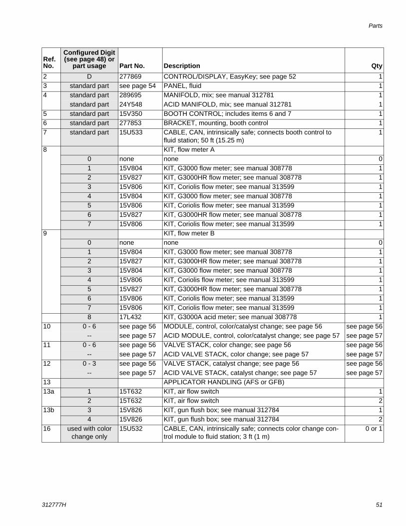
part usage Part No. Description Qty2 D 277869 CONTROL/DISPLAY, EasyKey; see page 52 13 standard part see page 54 PANEL, fluid 14 standard part 289695 MANIFOLD, mix; see manual 312781 1
standard part 24Y548 ACID MANIFOLD, mix; see manual 312781 15 standard part 15V350 BOOTH CONTROL; includes items 6 and 7 16 standard part 277853 BRACKET, mounting, booth control 17 standard part 15U533 CABLE, CAN, intrinsically safe; connects booth control to
fluid station; 50 ft (15.25 m)1
8 KIT, flow meter A0 none none 01 15V804 KIT, G3000 flow meter; see manual 308778 12 15V827 KIT, G3000HR flow meter; see manual 308778 13 15V806 KIT, Coriolis flow meter; see manual 313599 14 15V804 KIT, G3000 flow meter; see manual 308778 15 15V806 KIT, Coriolis flow meter; see manual 313599 16 15V827 KIT, G3000HR flow meter; see manual 308778 17 15V806 KIT, Coriolis flow meter; see manual 313599 1
9 KIT, flow meter B0 none none 01 15V804 KIT, G3000 flow meter; see manual 308778 12 15V827 KIT, G3000HR flow meter; see manual 308778 13 15V804 KIT, G3000 flow meter; see manual 308778 14 15V806 KIT, Coriolis flow meter; see manual 313599 15 15V827 KIT, G3000HR flow meter; see manual 308778 16 15V806 KIT, Coriolis flow meter; see manual 313599 17 15V806 KIT, Coriolis flow meter; see manual 313599 18 17L432 KIT, G3000A acid meter; see manual 308778 1
10 0 - 6 see page 56 MODULE, control, color/catalyst change; see page 56 see page 56-- see page 57 ACID MODULE, control, color/catalyst change; see page 57 see page 57
11 0 - 6 see page 56 VALVE STACK, color change; see page 56 see page 56-- see page 57 ACID VALVE STACK, color change; see page 57 see page 57
12 0 - 3 see page 56 VALVE STACK, catalyst change; see page 56 see page 56-- see page 57 ACID VALVE STACK, catalyst change; see page 57 see page 57
13 APPLICATOR HANDLING (AFS or GFB)13a 1 15T632 KIT, air flow switch 1
2 15T632 KIT, air flow switch 213b 3 15V826 KIT, gun flush box; see manual 312784 1
4 15V826 KIT, gun flush box; see manual 312784 216 used with color
change only15U532 CABLE, CAN, intrinsically safe; connects color change con-
trol module to fluid station; 3 ft (1 m)0 or 1
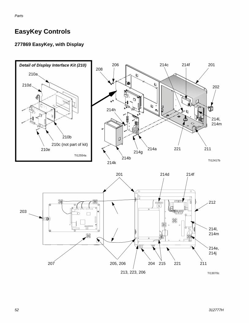
Parts
52 312777H
EasyKey Controls
277869 EasyKey, with Display
201
215
214f
213, 223, 206
211
221 211
202
203
204
214c 214f
218
209
208
207 205, 206
206
210a
212
221
TI13070c
TI12417b
TI12554a
214d
214e,214j
210e
210d
210b
Detail of Display Interface Kit (210) 201
214g214a
214k214b
214h
214l, 214m
214l, 214m
210c (not part of kit)
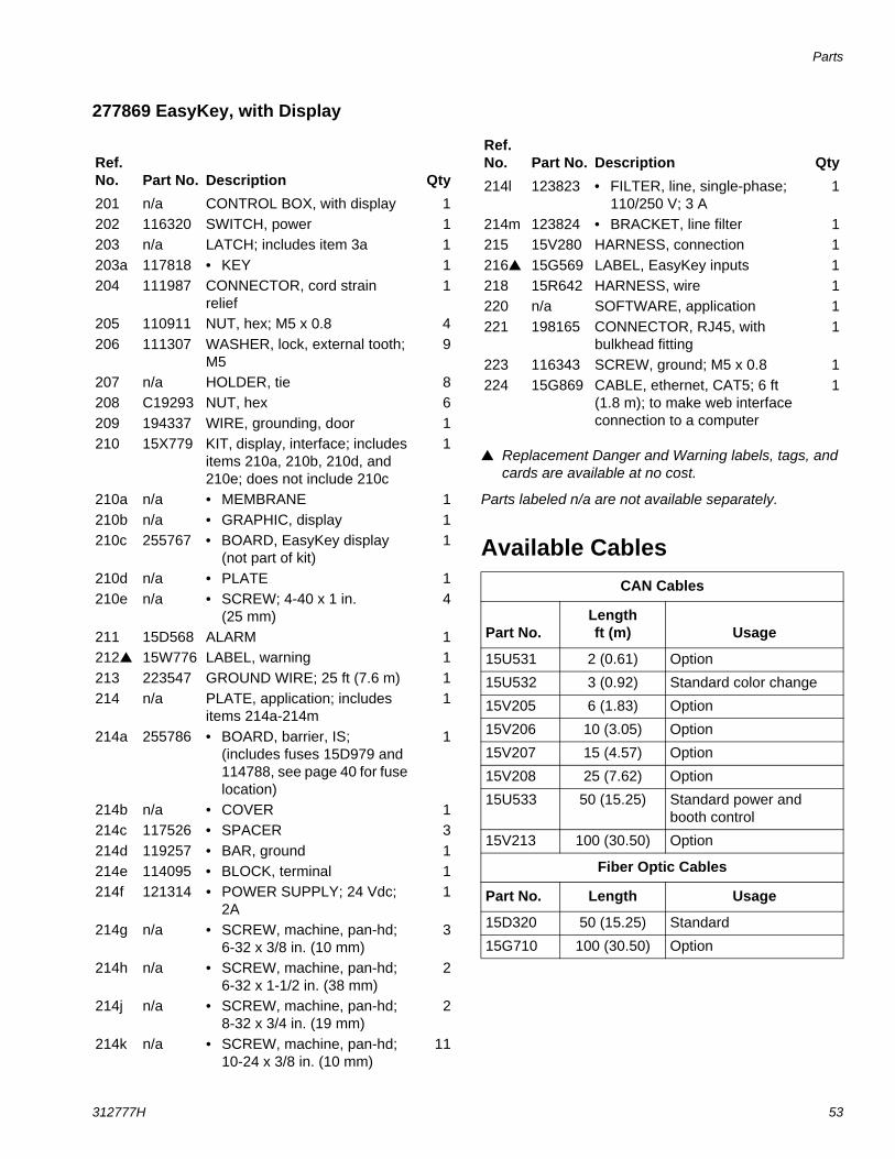
Parts
312777H 53
277869 EasyKey, with Display
Replacement Danger and Warning labels, tags, and cards are available at no cost.
Parts labeled n/a are not available separately.
Available Cables
Ref. No. Part No. Description Qty201 n/a CONTROL BOX, with display 1202 116320 SWITCH, power 1203 n/a LATCH; includes item 3a 1203a 117818 • KEY 1204 111987 CONNECTOR, cord strain
relief1
205 110911 NUT, hex; M5 x 0.8 4206 111307 WASHER, lock, external tooth;
M59
207 n/a HOLDER, tie 8208 C19293 NUT, hex 6209 194337 WIRE, grounding, door 1210 15X779 KIT, display, interface; includes
items 210a, 210b, 210d, and 210e; does not include 210c
1
210a n/a • MEMBRANE 1210b n/a • GRAPHIC, display 1210c 255767 • BOARD, EasyKey display
(not part of kit)1
210d n/a • PLATE 1210e n/a • SCREW; 4-40 x 1 in.
(25 mm)4
211 15D568 ALARM 1212 15W776 LABEL, warning 1213 223547 GROUND WIRE; 25 ft (7.6 m) 1214 n/a PLATE, application; includes
items 214a-214m1
214a 255786 • BOARD, barrier, IS; (includes fuses 15D979 and 114788, see page 40 for fuse location)
1
214b n/a • COVER 1214c 117526 • SPACER 3214d 119257 • BAR, ground 1214e 114095 • BLOCK, terminal 1214f 121314 • POWER SUPPLY; 24 Vdc;
2A1
214g n/a • SCREW, machine, pan-hd; 6-32 x 3/8 in. (10 mm)
3
214h n/a • SCREW, machine, pan-hd; 6-32 x 1-1/2 in. (38 mm)
2
214j n/a • SCREW, machine, pan-hd; 8-32 x 3/4 in. (19 mm)
2
214k n/a • SCREW, machine, pan-hd; 10-24 x 3/8 in. (10 mm)
11
214l 123823 • FILTER, line, single-phase; 110/250 V; 3 A
1
214m 123824 • BRACKET, line filter 1215 15V280 HARNESS, connection 1216 15G569 LABEL, EasyKey inputs 1218 15R642 HARNESS, wire 1220 n/a SOFTWARE, application 1221 198165 CONNECTOR, RJ45, with
bulkhead fitting1
223 116343 SCREW, ground; M5 x 0.8 1224 15G869 CABLE, ethernet, CAT5; 6 ft
(1.8 m); to make web interface connection to a computer
1
CAN Cables
Part No.Lengthft (m) Usage
15U531 2 (0.61) Option
15U532 3 (0.92) Standard color change
15V205 6 (1.83) Option
15V206 10 (3.05) Option
15V207 15 (4.57) Option
15V208 25 (7.62) Option
15U533 50 (15.25) Standard power and booth control
15V213 100 (30.50) Option
Fiber Optic Cables
Part No. Length Usage
15D320 50 (15.25) Standard
15G710 100 (30.50) Option
Ref. No. Part No. Description Qty
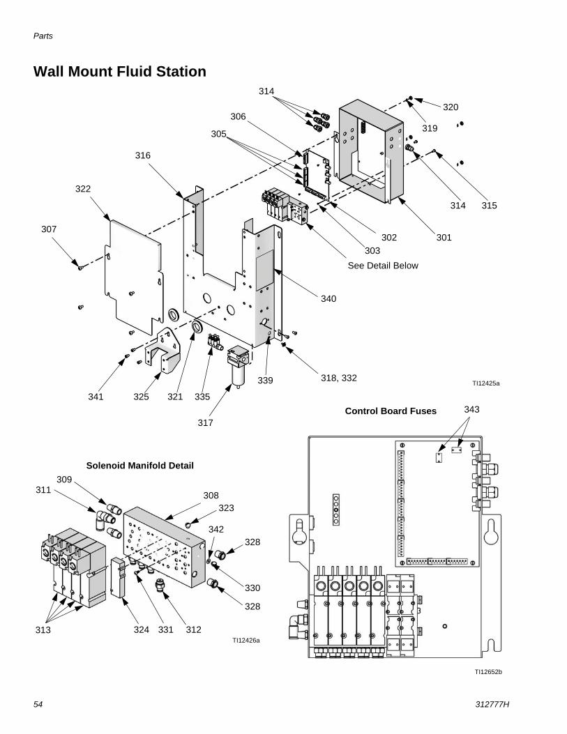
Parts
54 312777H
Wall Mount Fluid Station
331
301
323
315314
313
316
321
311
302
322
303
319
317
309
308
307
305
306
312
320
324
328
330
335
339
340
314
See Detail Below
318, 332
328
TI12425a
TI12426a
Solenoid Manifold Detail
342
325341
TI12652b
343Control Board Fuses
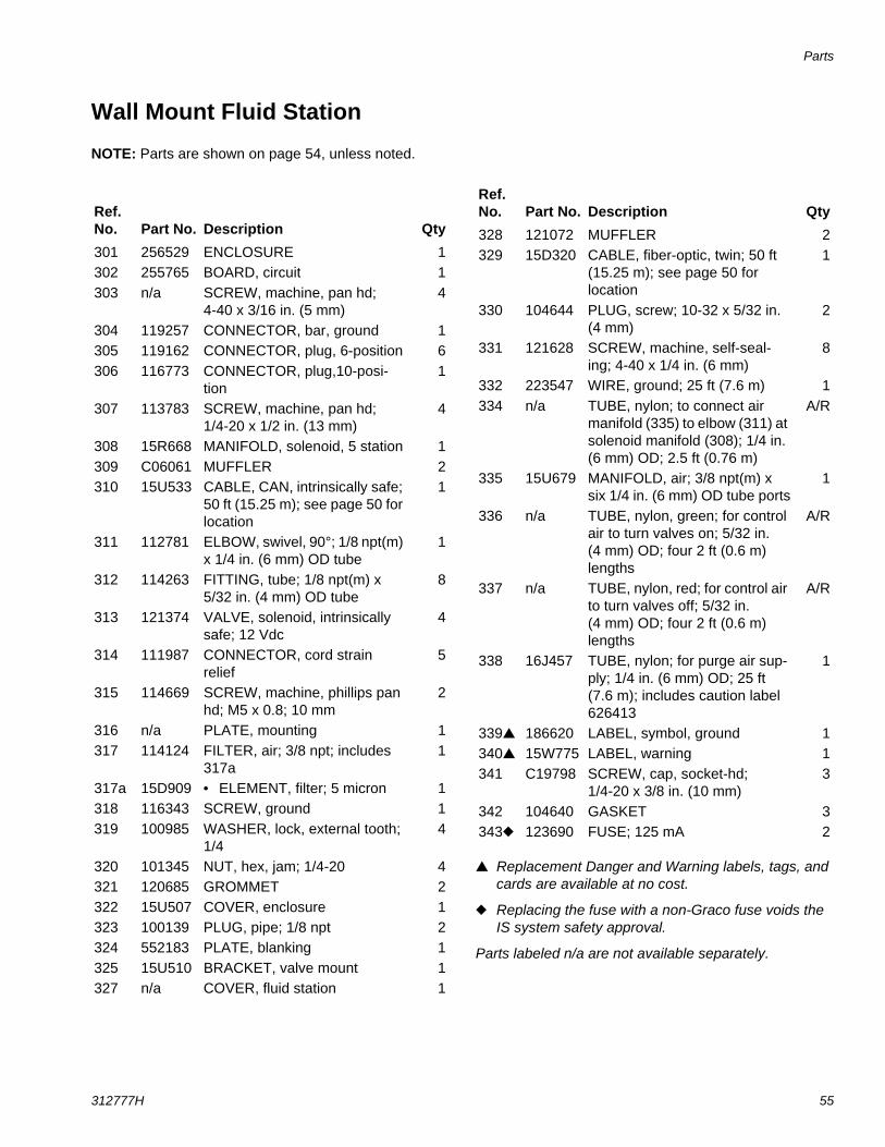
Parts
312777H 55
Wall Mount Fluid Station
NOTE: Parts are shown on page 54, unless noted.
Replacement Danger and Warning labels, tags, and cards are available at no cost.
Replacing the fuse with a non-Graco fuse voids the IS system safety approval.
Parts labeled n/a are not available separately.
Ref. No. Part No. Description Qty301 256529 ENCLOSURE 1302 255765 BOARD, circuit 1303 n/a SCREW, machine, pan hd;
4-40 x 3/16 in. (5 mm)4
304 119257 CONNECTOR, bar, ground 1305 119162 CONNECTOR, plug, 6-position 6306 116773 CONNECTOR, plug,10-posi-
tion1
307 113783 SCREW, machine, pan hd; 1/4-20 x 1/2 in. (13 mm)
4
308 15R668 MANIFOLD, solenoid, 5 station 1309 C06061 MUFFLER 2310 15U533 CABLE, CAN, intrinsically safe;
50 ft (15.25 m); see page 50 for location
1
311 112781 ELBOW, swivel, 90°; 1/8 npt(m) x 1/4 in. (6 mm) OD tube
1
312 114263 FITTING, tube; 1/8 npt(m) x 5/32 in. (4 mm) OD tube
8
313 121374 VALVE, solenoid, intrinsically safe; 12 Vdc
4
314 111987 CONNECTOR, cord strain relief
5
315 114669 SCREW, machine, phillips pan hd; M5 x 0.8; 10 mm
2
316 n/a PLATE, mounting 1317 114124 FILTER, air; 3/8 npt; includes
317a1
317a 15D909 • ELEMENT, filter; 5 micron 1318 116343 SCREW, ground 1319 100985 WASHER, lock, external tooth;
1/44
320 101345 NUT, hex, jam; 1/4-20 4321 120685 GROMMET 2322 15U507 COVER, enclosure 1323 100139 PLUG, pipe; 1/8 npt 2324 552183 PLATE, blanking 1325 15U510 BRACKET, valve mount 1327 n/a COVER, fluid station 1
328 121072 MUFFLER 2329 15D320 CABLE, fiber-optic, twin; 50 ft
(15.25 m); see page 50 for location
1
330 104644 PLUG, screw; 10-32 x 5/32 in. (4 mm)
2
331 121628 SCREW, machine, self-seal-ing; 4-40 x 1/4 in. (6 mm)
8
332 223547 WIRE, ground; 25 ft (7.6 m) 1334 n/a TUBE, nylon; to connect air
manifold (335) to elbow (311) at solenoid manifold (308); 1/4 in. (6 mm) OD; 2.5 ft (0.76 m)
A/R
335 15U679 MANIFOLD, air; 3/8 npt(m) x six 1/4 in. (6 mm) OD tube ports
1
336 n/a TUBE, nylon, green; for control air to turn valves on; 5/32 in. (4 mm) OD; four 2 ft (0.6 m) lengths
A/R
337 n/a TUBE, nylon, red; for control air to turn valves off; 5/32 in. (4 mm) OD; four 2 ft (0.6 m) lengths
A/R
338 16J457 TUBE, nylon; for purge air sup-ply; 1/4 in. (6 mm) OD; 25 ft (7.6 m); includes caution label 626413
1
339 186620 LABEL, symbol, ground 1340 15W775 LABEL, warning 1341 C19798 SCREW, cap, socket-hd;
1/4-20 x 3/8 in. (10 mm)3
342 104640 GASKET 3343 123690 FUSE; 125 mA 2
Ref. No. Part No. Description Qty
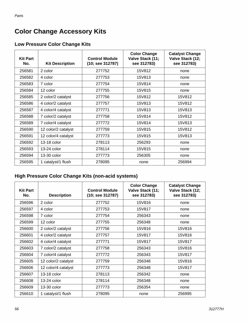
Parts
56 312777H
Color Change Accessory Kits
Low Pressure Color Change Kits
High Pressure Color Change Kits (non-acid systems)
Kit Part No. Kit Description
Control Module (10; see 312787)
Color Change Valve Stack (11;
see 312783)
Catalyst Change Valve Stack (12;
see 312783)
256581 2 color 277752 15V812 none
256582 4 color 277753 15V813 none
256583 7 color 277754 15V814 none
256584 12 color 277755 15V815 none
256585 2 color/2 catalyst 277756 15V812 15V812
256586 4 color/2 catalyst 277757 15V813 15V812
256587 4 color/4 catalyst 277771 15V813 15V813
256588 7 color/2 catalyst 277758 15V814 15V812
256589 7 color/4 catalyst 277772 15V814 15V813
256590 12 color/2 catalyst 277759 15V815 15V812
256591 12 color/4 catalyst 277773 15V815 15V813
256592 13-18 color 278113 256293 none
256593 13-24 color 278114 15V815 none
256594 13-30 color 277773 256305 none
256595 1 catalyst/1 flush 278095 none 256994
Kit Part No. Description
Control Module (10; see 312787)
Color Change Valve Stack (11;
see 312783)
Catalyst Change Valve Stack (12;
see 312783)
256596 2 color 277752 15V816 none
256597 4 color 277753 15V817 none
256598 7 color 277754 256343 none
256599 12 color 277755 256348 none
256600 2 color/2 catalyst 277756 15V816 15V816
256601 4 color/2 catalyst 277757 15V817 15V816
256602 4 color/4 catalyst 277771 15V817 15V817
256603 7 color/2 catalyst 277758 256343 15V816
256604 7 color/4 catalyst 277772 256343 15V817
256605 12 color/2 catalyst 277759 256348 15V816
256606 12 color/4 catalyst 277773 256348 15V817
256607 13-18 color 278113 256342 none
256608 13-24 color 278114 256348 none
256609 13-30 color 277773 256354 none
256610 1 catalyst/1 flush 278095 none 256995
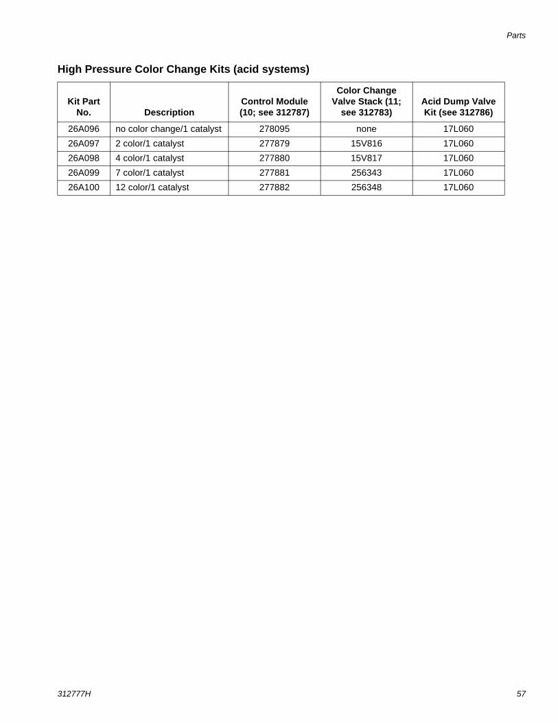
Parts
312777H 57
High Pressure Color Change Kits (acid systems)
Kit Part No. Description
Control Module (10; see 312787)
Color Change Valve Stack (11;
see 312783)Acid Dump Valve Kit (see 312786)
26A096 no color change/1 catalyst 278095 none 17L060
26A097 2 color/1 catalyst 277879 15V816 17L060
26A098 4 color/1 catalyst 277880 15V817 17L060
26A099 7 color/1 catalyst 277881 256343 17L060
26A100 12 color/1 catalyst 277882 256348 17L060

Parts
58 312777H
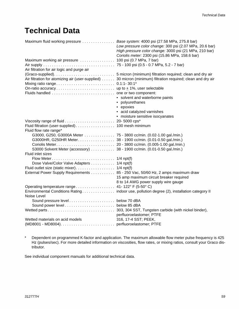
Technical Data
312777H 59
Technical Data
* Dependent on programmed K-factor and application. The maximum allowable flow meter pulse frequency is 425 Hz (pulses/sec). For more detailed information on viscosities, flow rates, or mixing ratios, consult your Graco dis-tributor.
See individual component manuals for additional technical data.
Maximum fluid working pressure . . . . . . . . . . . . . . . Base system: 4000 psi (27.58 MPa, 275.8 bar)Low pressure color change: 300 psi (2.07 MPa, 20.6 bar)High pressure color change: 3000 psi (21 MPa, 210 bar)Coriolis meter: 2300 psi (15.86 MPa, 158.6 bar)
Maximum working air pressure . . . . . . . . . . . . . . . . 100 psi (0.7 MPa, 7 bar)Air supply . . . . . . . . . . . . . . . . . . . . . . . . . . . . . . . . . 75 - 100 psi (0.5 - 0.7 MPa, 5.2 - 7 bar)Air filtration for air logic and purge air (Graco-supplied). . . . . . . . . . . . . . . . . . . . . . . . . . . . 5 micron (minimum) filtration required; clean and dry airAir filtration for atomizing air (user-supplied) . . . . . . 30 micron (minimum) filtration required; clean and dry airMixing ratio range. . . . . . . . . . . . . . . . . . . . . . . . . . . 0.1:1- 30:1*On-ratio accuracy . . . . . . . . . . . . . . . . . . . . . . . . . . . up to + 1%, user selectableFluids handled . . . . . . . . . . . . . . . . . . . . . . . . . . . . . one or two component:
• solvent and waterborne paints• polyurethanes• epoxies• acid catalyzed varnishes• moisture sensitive isocyanates
Viscosity range of fluid . . . . . . . . . . . . . . . . . . . . . . . 20- 5000 cps*Fluid filtration (user-supplied) . . . . . . . . . . . . . . . . . . 100 mesh minimumFluid flow rate range*
G3000, G250, G3000A Meter . . . . . . . . . . . . . .G3000HR, G250HR Meter. . . . . . . . . . . . . . . . .Coriolis Meter. . . . . . . . . . . . . . . . . . . . . . . . . . .S3000 Solvent Meter (accessory) . . . . . . . . . . .
75 - 3800 cc/min. (0.02-1.00 gal./min.)38 - 1900 cc/min. (0.01-0.50 gal./min.)20 - 3800 cc/min. (0.005-1.00 gal./min.)38 - 1900 cc/min. (0.01-0.50 gal./min.)
Fluid inlet sizesFlow Meter . . . . . . . . . . . . . . . . . . . . . . . . . . . . .Dose Valve/Color Valve Adapters . . . . . . . . . . .
1/4 npt(f)1/4 npt(f)
Fluid outlet size (static mixer) . . . . . . . . . . . . . . . . . . 1/4 npt(f)External Power Supply Requirements . . . . . . . . . . . 85 - 250 Vac, 50/60 Hz, 2 amps maximum draw
15 amp maximum circuit breaker required8 to 14 AWG power supply wire gauge
Operating temperature range . . . . . . . . . . . . . . . . . . 41- 122° F (5-50° C)Environmental Conditions Rating . . . . . . . . . . . . . . . indoor use, pollution degree (2), installation category IINoise Level
Sound pressure level . . . . . . . . . . . . . . . . . . . . .Sound power level . . . . . . . . . . . . . . . . . . . . . . .
below 70 dBAbelow 85 dBA
Wetted parts . . . . . . . . . . . . . . . . . . . . . . . . . . . . . . . 303, 304 SST, Tungsten carbide (with nickel binder), perfluoroelastomer; PTFE
Wetted materials on acid models(MD8001 - MD8004). . . . . . . . . . . . . . . . . . . . . . . . .
316, 17-4 SST; PEEK,perfluoroelastomer; PTFE

All written and visual data contained in this document reflects the latest product information available at the time of publication. Graco reserves the right to make changes at any time without notice.
Original instructions. This manual contains English. MM 312777Graco Headquarters: Minneapolis
International Offices: Belgium, China, Japan, Korea
GRACO INC. AND SUBSIDIARIES • P.O. BOX 1441 • MINNEAPOLIS MN 55440-1441 • USACopyright 2008, Graco Inc. All Graco manufacturing locations are registered to ISO 9001.
www.graco.comRevision H, October 2016
Graco Standard WarrantyGraco warrants all equipment referenced in this document which is manufactured by Graco and bearing its name to be free from defects in material and workmanship on the date of sale to the original purchaser for use. With the exception of any special, extended, or limited warranty published by Graco, Graco will, for a period of twelve months from the date of sale, repair or replace any part of the equipment determined by Graco to be defective. This warranty applies only when the equipment is installed, operated and maintained in accordance with Graco’s written recommendations.
This warranty does not cover, and Graco shall not be liable for general wear and tear, or any malfunction, damage or wear caused by faulty installation, misapplication, abrasion, corrosion, inadequate or improper maintenance, negligence, accident, tampering, or substitution of non-Graco component parts. Nor shall Graco be liable for malfunction, damage or wear caused by the incompatibility of Graco equipment with structures, accessories, equipment or materials not supplied by Graco, or the improper design, manufacture, installation, operation or maintenance of structures, accessories, equipment or materials not supplied by Graco.
This warranty is conditioned upon the prepaid return of the equipment claimed to be defective to an authorized Graco distributor for verification of the claimed defect. If the claimed defect is verified, Graco will repair or replace free of charge any defective parts. The equipment will be returned to the original purchaser transportation prepaid. If inspection of the equipment does not disclose any defect in material or workmanship, repairs will be made at a reasonable charge, which charges may include the costs of parts, labor, and transportation.
THIS WARRANTY IS EXCLUSIVE, AND IS IN LIEU OF ANY OTHER WARRANTIES, EXPRESS OR IMPLIED, INCLUDING BUT NOT LIMITED TO WARRANTY OF MERCHANTABILITY OR WARRANTY OF FITNESS FOR A PARTICULAR PURPOSE.
Graco’s sole obligation and buyer’s sole remedy for any breach of warranty shall be as set forth above. The buyer agrees that no other remedy (including, but not limited to, incidental or consequential damages for lost profits, lost sales, injury to person or property, or any other incidental or consequential loss) shall be available. Any action for breach of warranty must be brought within two (2) years of the date of sale.
GRACO MAKES NO WARRANTY, AND DISCLAIMS ALL IMPLIED WARRANTIES OF MERCHANTABILITY AND FITNESS FOR A PARTICULAR PURPOSE, IN CONNECTION WITH ACCESSORIES, EQUIPMENT, MATERIALS OR COMPONENTS SOLD BUT NOT MANUFACTURED BY GRACO. These items sold, but not manufactured by Graco (such as electric motors, switches, hose, etc.), are subject to the warranty, if any, of their manufacturer. Graco will provide purchaser with reasonable assistance in making any claim for breach of these warranties.
In no event will Graco be liable for indirect, incidental, special or consequential damages resulting from Graco supplying equipment hereunder, or the furnishing, performance, or use of any products or other goods sold hereto, whether due to a breach of contract, breach of warranty, the negligence of Graco, or otherwise.
FOR GRACO CANADA CUSTOMERSThe Parties acknowledge that they have required that the present document, as well as all documents, notices and legal proceedings entered into, given or instituted pursuant hereto or relating directly or indirectly hereto, be drawn up in English. Les parties reconnaissent avoir convenu que la rédaction du présente document sera en Anglais, ainsi que tous documents, avis et procédures judiciaires exécutés, donnés ou intentés, à la suite de ou en rapport, directement ou indirectement, avec les procédures concernées.
Graco Information For the latest information about Graco products, visit www.graco.com.
For patent information, see www.graco.com/patents.
TO PLACE AN ORDER, contact your Graco distributor or call to identify the nearest distributor.Phone: 612-623-6921 or Toll Free: 1-800-328-0211 Fax: 612-378-3505