Manual Supplement - Fluke Corporationassets.fluke.com/manuals/125_____umENG0102.pdfUsers Manual...
10
Manual Supplement © 2008 Fluke Corporation. All rights reserved. Printed in the Netherlands ® Manual Title: Users Manual Fluke 125 Supplement Issue: 2 Part Number: --- Part Number: 4822 872 08643 Print Date: Jan. 2007 Issue Date: Jul. 2008 Revision/Date: --- Page Count 9 This supplement contains information to extend the information presented in the Fluke 125 Users Manual. The extension concerns Chapter 4 – Fieldbus Measurements and more in particular Table 4-1. This table shows for each Fieldbus type the ScopeMeter channels and probe types to be used for testing. The purpose of this Manual Supplement is to give more information on how to connect Probe(s) and Ground Lead to the Fieldbus system under test. Bear in mind however that due to the variety of Bus Standards and Connectors used worldwide it is impossible to cover all situations. The connection solutions in this Supplement cover those most commonly found. Use of Probes: refer to page 0-2 and 0-3 of Users Manual for overview of accessories as suplied with Fluke 125. For most measurements the Shielded Test Leads STL120 (1:1) are used. To hook up the ScopeMeter’s COM terminal to a Bus System you can use the Black Test Lead. In noisy environments however it is advised to use the shorter ground lead with alligator clip (supplied with STL120) instead of the Black Test Lead. To hook up to bus line nodes you can use the Alligator Clips or Hook Clips that fit on to the STL120 tip. TP88 Back Probe Pins (optional) can be used to probe screw terminals at the wire entry point. Alligator Clips, Hook Clips, and the optional Back Probe Pins also fit on the tip of the VPS40 Probe (10:1) that is used to test some of the Fieldbus types. VPS40 is used on bus systems that are sensitive to the capacitive load of STL120 (225 pF against 15.5 pF for VPS40). When using a 10:1 probe other than VPS40, it must be adjusted for a good response! A poorly calibrated probe can introduce measurement errors. How to adjust is explained in chapter 2. The Banana-to-BNC Adapter BB120 may be used when testing systems with coaxial connection cables. If the system requires so you must add a coaxial 50 or 75 Ω termination at the BB120. As an alternative you may connect the VPS40 10:1 probe across a terminator in the system under test. Important. Fieldbusses often are controlling delicate processes that must not be disturbed. It is strongly recommended to contact the system manager before any connections are made! Suggestions, remarks, and questions on how to test Fieldbus Systems are much appreciated. Send your e-mail to: [email protected].
Transcript of Manual Supplement - Fluke Corporationassets.fluke.com/manuals/125_____umENG0102.pdfUsers Manual...

Manual Supplement
© 2008 Fluke Corporation. All rights reserved. Printed in the Netherlands
®
Manual Title: Users Manual Fluke 125 Supplement Issue: 2 Part Number: --- Part Number: 4822 872 08643 Print Date: Jan. 2007 Issue Date: Jul. 2008 Revision/Date: --- Page Count 9
This supplement contains information to extend the information presented in the Fluke 125 Users Manual. The extension concerns Chapter 4 – Fieldbus Measurements and more in particular Table 4-1. This table shows for each Fieldbus type the ScopeMeter channels and probe types to be used for testing. The purpose of this Manual Supplement is to give more information on how to connect Probe(s) and Ground Lead to the Fieldbus system under test. Bear in mind however that due to the variety of Bus Standards and Connectors used worldwide it is impossible to cover all situations. The connection solutions in this Supplement cover those most commonly found. Use of Probes: refer to page 0-2 and 0-3 of Users Manual for overview of accessories as suplied with Fluke 125. For most measurements the Shielded Test Leads STL120 (1:1) are used. To hook up the ScopeMeter’s COM terminal to a Bus System you can use the Black Test Lead. In noisy environments however it is advised to use the shorter ground lead with alligator clip (supplied with STL120) instead of the Black Test Lead. To hook up to bus line nodes you can use the Alligator Clips or Hook Clips that fit on to the STL120 tip. TP88 Back Probe Pins (optional) can be used to probe screw terminals at the wire entry point. Alligator Clips, Hook Clips, and the optional Back Probe Pins also fit on the tip of the VPS40 Probe (10:1) that is used to test some of the Fieldbus types. VPS40 is used on bus systems that are sensitive to the capacitive load of STL120 (225 pF against 15.5 pF for VPS40). When using a 10:1 probe other than VPS40, it must be adjusted for a good response! A poorly calibrated probe can introduce measurement errors. How to adjust is explained in chapter 2. The Banana-to-BNC Adapter BB120 may be used when testing systems with coaxial connection cables. If the system requires so you must add a coaxial 50 or 75 Ω termination at the BB120. As an alternative you may connect the VPS40 10:1 probe across a terminator in the system under test. Important. Fieldbusses often are controlling delicate processes that must not be disturbed. It is strongly recommended to contact the system manager before any connections are made! Suggestions, remarks, and questions on how to test Fieldbus Systems are much appreciated. Send your e-mail to: [email protected].

Users Manual Fluke 125 Manual Supplement
1
BUSHEALTH MEASUREMENTS, GENERAL. The Bushealth measurement is based upon the instrument’s Scope mode. In Scope mode the instrument displays the waveforms of the bus signals. Once a signal is captured it requires expert knowledge on how to interpret these signals. Bushealth makes signal interpretation very easy. The captured waveform(s) are compared against voltage and timing criteria as specified for the tested Bus Type, resulting in clear quality information of these criteria (OK/V, marginal/!, or out of range/X). In some bus systems (AS-i for instance) the protocol uses continuous polling of all devices in a fixed time schedule so that there is continuous data traffic. Other systems such as RS-232 only carry data when settings are changed. Bushealth requires continuous data traffic to perform its measurements. In case of very low data repetition rates, the banner ‘NO DATA’ is displayed. In systems with low data rates, it is recommended to increase the data rate by e.g. knob operation. Contact the system manager for this. For Bus measurements that use input A and B (CAN, Modbus RS-485, Profibus DP, RS-485) it is important that the Common Mode component at the inputs is as small as possible. This component may consist of 50 or 60 Hz hum or other noise. Common mode signals may affect measurement results. In case of doubt, use SCOPE mode to investigate the waveforms at A and B. In case of visible interference, look for a ground lead attachment point in the system under test that shows the smallest interference. BUSHEALTH MEASUREMENTS, TIPS AND HINTS LISTED PER BUSTYPE. AS-i Bus. The Actuator-Sensor-Interface (AS-i) is used to control on/off devices at the factory floor. The bus consists of 2 wires marked + and – that carry a 30 Vdc supply with superimposed data. The AS-i protocol uses continuous polling of all devices in a fixed time schedule so that there is continuous data traffic. To check AS-i, ScopeMeter Channel A is on and alternately AC coupled for data or DC coupled to test 30 Vdc. The recommended probe is STL120 (1:1). The probe tip must be connected to the + (positive) wire; the COM input (or Black Ground Lead) to the – (negative) wire. Connection between controller and devices is made using a dedicated yellow flat cable as shown in the figure below (cross section). Connection to the devices is done with piercing connectors. To connect Probe Tip and Black Ground Lead to + (brown conductor) and – (blue), the TP88 Back Probe Pins (optional) can be used to probe screw terminals at the end of the flat cable or as piercing probes. The material of the flat cable also allows to pierce the pin into it. After removal of the pin the material closes again. As-i also uses M12-connectors for data as well as on/off signals. The figure below shows where to find + and – on on such a connector.
COM Ch. A
1: Ch. A (+)
4
3: COM (-)
25
M12 CONNECTOR (FEMALE)

Manual Supplement Users Manual Fluke 125
2
CAN Bus/DeviceNet. The Controller Area Network (CAN) is used on board of automobiles and also in industrial applications. The industrial bussystem DeviceNet is based on CAN hardware. CAN is a two-wire differential bus used to control actuators and to read out sensors. The bus allows data exchange between different devices. The signal behavior in time is shown in the figure below. The signal wires are marked CAN_L and CAN_H. There is also a common (reference wire) CAN_GND. Data traffic is continuous. To check CAN Bus, ScopeMeter Channel A and B are on and DC coupled. The recommended probes are STL120 (1:1). Probe Tip A must be connected to CAN_H, B to CAN_L, and COM to CAN_GND. Bus lines can be reached with Back Probe Pins at screw terminals at a device’s wire entry point: wire colors commonly used are white for CAN_H, blue for CAN_L, and black for CAN_GND. Alternatively you can use a third party DB-9 to 4 mm banana breakout box. In addition the figure below shows the pinning of a DB-9 female connector and a typical Automotive (OBD2) connector. Bear in mind that some automobile manufacturers leave bus signals at the connector default on, other manufacturers require bus signals to be enabled via an external controller.
3.5 V
2.5 V
1.5 V
CAN_H Connect to Ch. A
CAN_L Connect to Ch. B
Ground Connect to COM
0 V
CAN_HCAN_LGround
1
26
3
4
5
7
8
9
DB-9 (FEMALE)
9 16High Speed:HS_CAN_H: Pin 6 / HS_CAN_L: Pin 14Medium Speed:MS_CAN_H: Pin 3 / MS_CAN_L: Pin 11Common (Signal Ground): Pin 5Battery: Plus: Pin 16 / Minus: Pin 4
1 OBD2 (FEMALE) 8
Interbus S. Is used in Process Industry and Factory Automation such as Assembly, Welding, and Materials Handling machines. Controller and Devices are arranged in a ring system as shown in the figure below. Interconnection between the devices is achieved via a Twisted Pair of lines DO (Data Out, yellow wire) / Not-DO (green) and another pair DI (Data In, gray) / Not-DI (pink). Data traffic is continuous, passing data packets through the chain of devices. To check Interbus S, ScopeMeter Channel A is on and DC coupled. The recommended probe is VPS40 (10:1). The probe tip must be connected to the DO (or DI) wire; the COM input (or Black Ground Lead) to the Not-DO (or Not-DI) wire. The wires can be reached with Back Probe Pins at screw terminals at a device’s wire entry point: for instance at a Junction Box. In addition the figure below shows the pinning of a DB-9 female connector wired for Interbus S.
CONTROLLER DEVICE 1 DEVICE N DO DI DO DODI DI
Ground
DODI

Users Manual Fluke 125 Manual Supplement
3
ControlNet. Is a network system used for high performance automation and process control. Connection between devices is achieved via 75 Ω coaxial cables. The figure below shows a typical system layout. Data traffic is continuous.
To check ControlNet, ScopeMeter Channel A is on and DC coupled. The recommended Banana to BNC Adapter BB120 (1:1) allows Channel A to connect with BNC cables. To connect to the System Under Test use a PM9083 male BNC to dual Female BNC adapter (T-piece, optional), and an extra BNC cable (PM9092, optional) as shown in the figure below. Bear in mind that in ControlNet cabling must not be disconnected during normal process operation. Some systems provide a Coaxial Breakout to make connection to BB120. Use a short coaxial cable to minimize load on to the system.
PASSIVE TAP
PM9083BB120
PASSIVE TAP
PASSIVE TAP
COAX COAX COAX
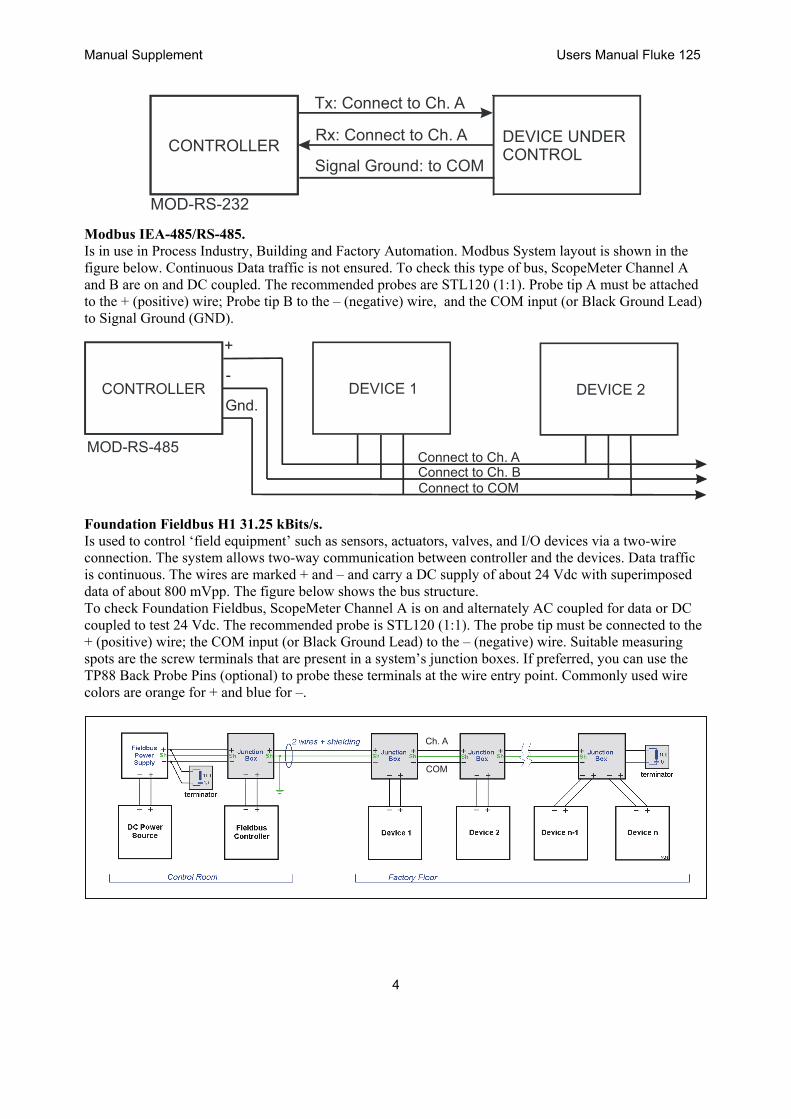
Modbus IEA-232/RS-232. Is in use in Process Industry, Building and Factory Automation. Modbus RS-232 is used for point-to-point communication. System layout is shown in the figure below. Continuous Data traffic is not ensured. To check this type of bus, ScopeMeter Channel A is on and DC coupled. The recommended probe is STL120 (1:1). The probe tip must be connected to the Tx (Transmit) or Rx (Receive) wire; the COM input (or Black Ground Lead) to the Signal Ground. In case there are handshake lines, they can be measured as well as far as V-Levels are concerned.
Manual Supplement Users Manual Fluke 125
4
CONTROLLER DEVICE UNDER CONTROL
Tx: Connect to Ch. A
Rx: Connect to Ch. A
Signal Ground: to COM
MOD-RS-232 Modbus IEA-485/RS-485. Is in use in Process Industry, Building and Factory Automation. Modbus System layout is shown in the figure below. Continuous Data traffic is not ensured. To check this type of bus, ScopeMeter Channel A and B are on and DC coupled. The recommended probes are STL120 (1:1). Probe tip A must be attached to the + (positive) wire; Probe tip B to the – (negative) wire, and the COM input (or Black Ground Lead) to Signal Ground (GND).
CONTROLLER DEVICE 1 DEVICE 2
+
-
Gnd.
Connect to Ch. AConnect to Ch. BConnect to COM
Foundation Fieldbus H1 31.25 kBits/s. Is used to control ‘field equipment’ such as sensors, actuators, valves, and I/O devices via a two-wire connection. The system allows two-way communication between controller and the devices. Data traffic is continuous. The wires are marked + and – and carry a DC supply of about 24 Vdc with superimposed data of about 800 mVpp. The figure below shows the bus structure. To check Foundation Fieldbus, ScopeMeter Channel A is on and alternately AC coupled for data or DC coupled to test 24 Vdc. The recommended probe is STL120 (1:1). The probe tip must be connected to the + (positive) wire; the COM input (or Black Ground Lead) to the – (negative) wire. Suitable measuring spots are the screw terminals that are present in a system’s junction boxes. If preferred, you can use the TP88 Back Probe Pins (optional) to probe these terminals at the wire entry point. Commonly used wire colors are orange for + and blue for –.
Ch. A
COM

Users Manual Fluke 125 Manual Supplement
5
Note: Foundation Fieldbus H2 1.0 – 2.5 MBit/s is removed from the selection menu (Software version V03.04 onwards) because this standard was never used. Therefor no connection examples are given for this bustype. Profibus DP/RS-485. Profibus DP (Decentralized Periphery) is an open Fieldbus standard used in Process Industry and Factory Automation. It is optimized for speed, efficiency, and low connection costs and allows for multiple data senders and receivers to be connected to an ongoing cable. Data traffic is continuous. To check this bustype, ScopeMeter Channel A and B are on and DC coupled. The recommended probes are STL120 (1:1). Probe tip A must be attached to the A (positive; usually green) wire; Probe tip B to the B (negative; usually red) wire, and the COM input (or Black Ground Lead) to Data Ground (DGND). Cabling and some connector examples are shown in the figures below. Please note that cables often incorporate termination resistors at the end of the network chain.
Channel A
Channel B
COM
COM
Green
Red

Manual Supplement Users Manual Fluke 125
6
Profibus PA/31.25 kBits/s. Profibus PA (Process Automation) is optimized for process control with focus on explosion safety. The wires are marked Data + and Data – and carry a DC supply with superimposed data. Additionally there are wires with DC power only. Data traffic is continuous. To check this bustype, ScopeMeter Channel A is on and alternately AC coupled for data or DC coupled to test the DC supply. The recommended probe is STL120 (1:1). The probe tip must be connected to the Data + line; the COM input (or Black Ground Lead) to the Data – line. The figures below show some connector types.
A: Data+ and PwrB: Data- and PwrC: Optional Pwr+D: Optional Pwr-
Warning. When planning tests on this bustype, make sure the proper safety rules are adhered to! Ethernet Coax/10Base2. To check this bustype, ScopeMeter Channel A is on and DC coupled. The recommended Banana to BNC Adapter BB120 (1:1) allows Channel A to connect with BNC cables. To connect to the System Under Test use a PM9083 male BNC to dual Female BNC adapter (T-piece, optional), and an extra BNC cable (PM9092, optional) as shown in the figure below. Bear in mind that in Ethernet cabling should only be interrupted for a few seconds during normal process operation. Data traffic usually is continuous.
COAXCOAX COAX
PM9083BB120
PASSIVETAP
PASSIVETAP
PASSIVETAP
DEVICE 1 DEVICE 2 DEVICE 3

Users Manual Fluke 125 Manual Supplement
7
Ethernet Twisted pair/10BaseT. To check this bustype, ScopeMeter Channel A is on and DC coupled. The recommended probe is VPS40 (10:1), Channel A is on and DC coupled. The probe tip must be connected to the TD+ or RD+ wire; the COM input (or Black Ground Lead) to the TD– or RD– wire. Data traffic is not always continuous. The wires can be reached with Back Probe Pins TP88 (optional) at screw terminals at a device’s wire entry point: for instance at a Junction Box. The right-hand figure shows pinning and wire colors of a RJ-45 connector.
TD+
RD+
TD-
RD-
OR
CABLE
Pin 1: TD+ (brown)Pin 2: TD- (brown/white)Pin 3: RD+ (orange)Pin 4Pin 5Pin 6: RD- (orange/white)Pin 7Pin 8
RS-232 Bus. RS-232 allows two-way communication between a controller and a device such as modem, printer, or sensor. Per device a dedicated link is needed. Initially the RS-232 definition offered an extensive handshake protocol with separate handshake lines (hardware handshake); later software handshake allowed data exchange via only 2 lines (plus ground). Data rates may be low, depending on the application. To check this bustype, ScopeMeter Channel A is on and DC coupled. The recommended probe is STL120 (1:1). The probe tip must be connected to the Tx (Transmit) or Rx (Receive) wire; the COM input (or Black Ground Lead) to the Signal Ground. In case there are handshake lines, they each can be checked individually because all use the same voltage levels. The figure below shows a Female DB-9 connector wired for hardware handshake. Lines used for software handshake are indicated with black dots.
RS-485 Bus. The RS-485 definition specifies differential (balanced) data lines that are referenced to a ground level. Because of this, noise immunity is better than for RS-232. The impedance between the lines is 120 Ω. RS-485 allows for multiple transmitters and receivers to be connected to the same bus. Data transmission is adressed to a dedicated receiver. Data traffic is not continuous.
Manual Supplement Users Manual Fluke 125
8
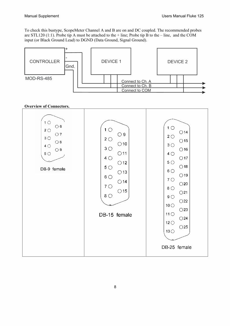
To check this bustype, ScopeMeter Channel A and B are on and DC coupled. The recommended probes are STL120 (1:1). Probe tip A must be attached to the + line; Probe tip B to the – line, and the COM input (or Black Ground Lead) to DGND (Data Ground, Signal Ground).
CONTROLLER DEVICE 1 DEVICE 2
+
-
Gnd.
Connect to Ch. AConnect to Ch. BConnect to COM
Overview of Connectors.

Users Manual Fluke 125 Manual Supplement
9