Manual: Rosemount 3051S Electric Remote Sensor … · 3.2 Safety messages ... 3.5.5 Module...
80
Reference Manual 00809-0100-4804, Rev DA May 2018 Rosemount ™ 3051S Electronic Remote Sensor (ERS) ™ System
Transcript of Manual: Rosemount 3051S Electric Remote Sensor … · 3.2 Safety messages ... 3.5.5 Module...

Reference Manual00809-0100-4804, Rev DA
May 2018
Rosemount™ 3051S Electronic Remote Sensor (ERS)™ System


Reference Manual 00809-0100-4804, Rev DA
ContentsMay 2018
Contents
1Section 1: Introduction1.1 Using this manual . . . . . . . . . . . . . . . . . . . . . . . . . . . . . . . . . . . . . . . . . . . . . . . . . . . . . . . . . . . . . . . . . 1
1.2 Product recycling/disposal. . . . . . . . . . . . . . . . . . . . . . . . . . . . . . . . . . . . . . . . . . . . . . . . . . . . . . . . . . 1
2Section 2: Installation2.1 Overview . . . . . . . . . . . . . . . . . . . . . . . . . . . . . . . . . . . . . . . . . . . . . . . . . . . . . . . . . . . . . . . . . . . . . . . . . 3
2.2 Safety messages. . . . . . . . . . . . . . . . . . . . . . . . . . . . . . . . . . . . . . . . . . . . . . . . . . . . . . . . . . . . . . . . . . . 3
2.3 Models covered . . . . . . . . . . . . . . . . . . . . . . . . . . . . . . . . . . . . . . . . . . . . . . . . . . . . . . . . . . . . . . . . . . . 4
2.4 Considerations . . . . . . . . . . . . . . . . . . . . . . . . . . . . . . . . . . . . . . . . . . . . . . . . . . . . . . . . . . . . . . . . . . . . 5
2.4.1 General . . . . . . . . . . . . . . . . . . . . . . . . . . . . . . . . . . . . . . . . . . . . . . . . . . . . . . . . . . . . . . . . . . . . . 5
2.4.2 Mechanical. . . . . . . . . . . . . . . . . . . . . . . . . . . . . . . . . . . . . . . . . . . . . . . . . . . . . . . . . . . . . . . . . . 5
2.4.3 Environmental. . . . . . . . . . . . . . . . . . . . . . . . . . . . . . . . . . . . . . . . . . . . . . . . . . . . . . . . . . . . . . . 6
2.5 Installation procedures . . . . . . . . . . . . . . . . . . . . . . . . . . . . . . . . . . . . . . . . . . . . . . . . . . . . . . . . . . . . . 8
2.5.1 Identify Rosemount ERS Sensors . . . . . . . . . . . . . . . . . . . . . . . . . . . . . . . . . . . . . . . . . . . . . . . 8
2.5.2 Mount each Rosemount ERS Sensor . . . . . . . . . . . . . . . . . . . . . . . . . . . . . . . . . . . . . . . . . . . . 8
2.5.3 Process connections . . . . . . . . . . . . . . . . . . . . . . . . . . . . . . . . . . . . . . . . . . . . . . . . . . . . . . . . 11
2.5.4 Consider housing orientation. . . . . . . . . . . . . . . . . . . . . . . . . . . . . . . . . . . . . . . . . . . . . . . . . 13
2.5.5 Configure security and alarm . . . . . . . . . . . . . . . . . . . . . . . . . . . . . . . . . . . . . . . . . . . . . . . . . 14
2.5.6 Connect wiring and power up . . . . . . . . . . . . . . . . . . . . . . . . . . . . . . . . . . . . . . . . . . . . . . . . 15
2.5.7 Grounding . . . . . . . . . . . . . . . . . . . . . . . . . . . . . . . . . . . . . . . . . . . . . . . . . . . . . . . . . . . . . . . . . 19
2.6 Rosemount manifolds. . . . . . . . . . . . . . . . . . . . . . . . . . . . . . . . . . . . . . . . . . . . . . . . . . . . . . . . . . . . . 21
2.6.1 Rosemount 305 Manifold installation procedure. . . . . . . . . . . . . . . . . . . . . . . . . . . . . . . . 22
2.6.2 Rosemount 304 Manifold installation procedure. . . . . . . . . . . . . . . . . . . . . . . . . . . . . . . . 22
2.6.3 Rosemount 306 Manifold installation procedure. . . . . . . . . . . . . . . . . . . . . . . . . . . . . . . . 23
2.6.4 Manifold valve configurations . . . . . . . . . . . . . . . . . . . . . . . . . . . . . . . . . . . . . . . . . . . . . . . . 23
3Section 3: Configuration3.1 Overview . . . . . . . . . . . . . . . . . . . . . . . . . . . . . . . . . . . . . . . . . . . . . . . . . . . . . . . . . . . . . . . . . . . . . . . . 25
3.2 Safety messages. . . . . . . . . . . . . . . . . . . . . . . . . . . . . . . . . . . . . . . . . . . . . . . . . . . . . . . . . . . . . . . . . . 25
3.2.1 Setting the loop to manual . . . . . . . . . . . . . . . . . . . . . . . . . . . . . . . . . . . . . . . . . . . . . . . . . . . 26
3.3 Wiring diagrams. . . . . . . . . . . . . . . . . . . . . . . . . . . . . . . . . . . . . . . . . . . . . . . . . . . . . . . . . . . . . . . . . . 26
3.4 Basic setup . . . . . . . . . . . . . . . . . . . . . . . . . . . . . . . . . . . . . . . . . . . . . . . . . . . . . . . . . . . . . . . . . . . . . . 26
3.4.1 Device tagging . . . . . . . . . . . . . . . . . . . . . . . . . . . . . . . . . . . . . . . . . . . . . . . . . . . . . . . . . . . . . 27
3.4.2 Units of measure. . . . . . . . . . . . . . . . . . . . . . . . . . . . . . . . . . . . . . . . . . . . . . . . . . . . . . . . . . . . 27
3.4.3 Damping . . . . . . . . . . . . . . . . . . . . . . . . . . . . . . . . . . . . . . . . . . . . . . . . . . . . . . . . . . . . . . . . . . 27
iContents

Reference Manual00809-0100-4804, Rev DA
ContentsMay 2018
3.4.4 Variable mapping . . . . . . . . . . . . . . . . . . . . . . . . . . . . . . . . . . . . . . . . . . . . . . . . . . . . . . . . . . . 28
3.4.5 Analog output . . . . . . . . . . . . . . . . . . . . . . . . . . . . . . . . . . . . . . . . . . . . . . . . . . . . . . . . . . . . . . 28
3.4.6 Alarm and saturation levels . . . . . . . . . . . . . . . . . . . . . . . . . . . . . . . . . . . . . . . . . . . . . . . . . . 29
3.5 Additional configuration . . . . . . . . . . . . . . . . . . . . . . . . . . . . . . . . . . . . . . . . . . . . . . . . . . . . . . . . . . 30
3.5.1 Local display . . . . . . . . . . . . . . . . . . . . . . . . . . . . . . . . . . . . . . . . . . . . . . . . . . . . . . . . . . . . . . . 30
3.5.2 Burst mode . . . . . . . . . . . . . . . . . . . . . . . . . . . . . . . . . . . . . . . . . . . . . . . . . . . . . . . . . . . . . . . . 30
3.5.3 Multidrop communication . . . . . . . . . . . . . . . . . . . . . . . . . . . . . . . . . . . . . . . . . . . . . . . . . . . 31
3.5.4 Scaled variable . . . . . . . . . . . . . . . . . . . . . . . . . . . . . . . . . . . . . . . . . . . . . . . . . . . . . . . . . . . . . 32
3.5.5 Module assignments . . . . . . . . . . . . . . . . . . . . . . . . . . . . . . . . . . . . . . . . . . . . . . . . . . . . . . . . 37
3.5.6 Process alerts. . . . . . . . . . . . . . . . . . . . . . . . . . . . . . . . . . . . . . . . . . . . . . . . . . . . . . . . . . . . . . . 38
3.6 HART menu trees . . . . . . . . . . . . . . . . . . . . . . . . . . . . . . . . . . . . . . . . . . . . . . . . . . . . . . . . . . . . . . . . . 39
4Section 4: Operation and Maintenance4.1 Overview . . . . . . . . . . . . . . . . . . . . . . . . . . . . . . . . . . . . . . . . . . . . . . . . . . . . . . . . . . . . . . . . . . . . . . . . 43
4.2 Safety messages. . . . . . . . . . . . . . . . . . . . . . . . . . . . . . . . . . . . . . . . . . . . . . . . . . . . . . . . . . . . . . . . . . 43
4.3 Calibration. . . . . . . . . . . . . . . . . . . . . . . . . . . . . . . . . . . . . . . . . . . . . . . . . . . . . . . . . . . . . . . . . . . . . . . 44
4.3.1 Calibration overview . . . . . . . . . . . . . . . . . . . . . . . . . . . . . . . . . . . . . . . . . . . . . . . . . . . . . . . . 44
4.3.2 PHI and PLO sensor calibration . . . . . . . . . . . . . . . . . . . . . . . . . . . . . . . . . . . . . . . . . . . . . . . 45
4.3.3 DP calibration . . . . . . . . . . . . . . . . . . . . . . . . . . . . . . . . . . . . . . . . . . . . . . . . . . . . . . . . . . . . . . 46
4.3.4 Analog output trim . . . . . . . . . . . . . . . . . . . . . . . . . . . . . . . . . . . . . . . . . . . . . . . . . . . . . . . . . 47
4.3.5 Recall factory trim . . . . . . . . . . . . . . . . . . . . . . . . . . . . . . . . . . . . . . . . . . . . . . . . . . . . . . . . . . 47
4.4 Functional tests . . . . . . . . . . . . . . . . . . . . . . . . . . . . . . . . . . . . . . . . . . . . . . . . . . . . . . . . . . . . . . . . . . 48
4.4.1 Find device. . . . . . . . . . . . . . . . . . . . . . . . . . . . . . . . . . . . . . . . . . . . . . . . . . . . . . . . . . . . . . . . . 48
4.5 Field upgrades and replacements. . . . . . . . . . . . . . . . . . . . . . . . . . . . . . . . . . . . . . . . . . . . . . . . . . . 49
4.5.1 Disassembly considerations . . . . . . . . . . . . . . . . . . . . . . . . . . . . . . . . . . . . . . . . . . . . . . . . . . 49
4.5.2 Labeling . . . . . . . . . . . . . . . . . . . . . . . . . . . . . . . . . . . . . . . . . . . . . . . . . . . . . . . . . . . . . . . . . . . 49
4.5.3 Remove the terminal block. . . . . . . . . . . . . . . . . . . . . . . . . . . . . . . . . . . . . . . . . . . . . . . . . . . 49
4.5.4 Removing the electronics . . . . . . . . . . . . . . . . . . . . . . . . . . . . . . . . . . . . . . . . . . . . . . . . . . . . 50
4.5.5 Remove the SuperModule from the housing . . . . . . . . . . . . . . . . . . . . . . . . . . . . . . . . . . . 51
4.5.6 Attach the SuperModule to the housing . . . . . . . . . . . . . . . . . . . . . . . . . . . . . . . . . . . . . . . 51
4.5.7 Install electronics assembly . . . . . . . . . . . . . . . . . . . . . . . . . . . . . . . . . . . . . . . . . . . . . . . . . . 51
4.5.8 Install the terminal block. . . . . . . . . . . . . . . . . . . . . . . . . . . . . . . . . . . . . . . . . . . . . . . . . . . . . 52
4.5.9 Reassemble the process flange . . . . . . . . . . . . . . . . . . . . . . . . . . . . . . . . . . . . . . . . . . . . . . . 52
5Section 5: Troubleshooting5.1 Overview . . . . . . . . . . . . . . . . . . . . . . . . . . . . . . . . . . . . . . . . . . . . . . . . . . . . . . . . . . . . . . . . . . . . . . . . 55
5.2 Device overview . . . . . . . . . . . . . . . . . . . . . . . . . . . . . . . . . . . . . . . . . . . . . . . . . . . . . . . . . . . . . . . . . . 55
ii Contents
Reference Manual 00809-0100-4804, Rev DA
ContentsMay 2018
5.2.1 HART host diagnostics. . . . . . . . . . . . . . . . . . . . . . . . . . . . . . . . . . . . . . . . . . . . . . . . . . . . . . . 55
5.2.2 LCD display diagnostics. . . . . . . . . . . . . . . . . . . . . . . . . . . . . . . . . . . . . . . . . . . . . . . . . . . . . . 55
5.3 Measurement quality status . . . . . . . . . . . . . . . . . . . . . . . . . . . . . . . . . . . . . . . . . . . . . . . . . . . . . . . 59
5.4 Service support. . . . . . . . . . . . . . . . . . . . . . . . . . . . . . . . . . . . . . . . . . . . . . . . . . . . . . . . . . . . . . . . . . . 59
6Section 6: Safety Instrumented Systems Requirements6.1 Safety Instrumented Systems (SIS) Certification . . . . . . . . . . . . . . . . . . . . . . . . . . . . . . . . . . . . . . 61
6.1.1 Rosemount ERS Systems safety certified identification . . . . . . . . . . . . . . . . . . . . . . . . . . 61
6.1.2 Installation in SIS applications . . . . . . . . . . . . . . . . . . . . . . . . . . . . . . . . . . . . . . . . . . . . . . . . 61
6.1.3 Configuring in SIS applications . . . . . . . . . . . . . . . . . . . . . . . . . . . . . . . . . . . . . . . . . . . . . . . 62
6.1.4 Rosemount 3051S SIS operation and maintenance. . . . . . . . . . . . . . . . . . . . . . . . . . . . . . 63
6.1.5 Inspection . . . . . . . . . . . . . . . . . . . . . . . . . . . . . . . . . . . . . . . . . . . . . . . . . . . . . . . . . . . . . . . . . 63
AAppendix A: Reference DataA.1 Product Certifications . . . . . . . . . . . . . . . . . . . . . . . . . . . . . . . . . . . . . . . . . . . . . . . . . . . . . . . . . . . . . 65
A.2 Ordering Information, Specifications, and Drawings . . . . . . . . . . . . . . . . . . . . . . . . . . . . . . . . . . 65
iiiContents

iv
Reference Manual00809-0100-4804, Rev DA
ContentsMay 2018
Contents

Reference Manual 00809-0100-4804, Rev DA
Title PageMay 2018
Rosemount™ 3051S Electronic Remote Sensor (ERS)™ System
NOTICE
Read this manual before working with the product. For personal and system safety, and for optimum product performance, make sure you thoroughly understand the contents before installing, using, or maintaining this product.
For technical assistance, contacts are listed below:
Customer CentralTechnical support, quoting, and order-related questions.
Americas 1 800 999 9307
Europe +41 (0) 41 768 6111
Middle east +971 4 811 8100
Asia +65 6777 8211
North American Response CenterEquipment service needs.
1-800-654-7768 (24 hours—includes Canada)
Outside of these areas, contact your local Emerson™ representative.
The products described in this document are NOT designed for nuclear-qualified applications. Using non-nuclear qualified products in applications that require nuclear-qualified hardware or products may cause inaccurate readings.
For information on Rosemount nuclear-qualified products, contact your local Emerson Sales Representative.
vTitle Page

Reference Manual00809-0100-4804, Rev DA
Title PageMay 2018
Failure to follow these installation guidelines could result in death or serious injury.
Make sure only qualified personnel perform the installation.
Explosions could result in death or serious injury. Do not remove the housing covers in explosive atmospheres when the circuit is live.
Before connecting a Field Communicator in an explosive atmosphere, make sure the instruments in the loop are installed in accordance with intrinsically safe or non-incendive field wiring practices.
Both housing covers must be fully engaged to meet flameproof/explosion-proof requirements.
Verify the operating atmosphere of the transmitter is consistent with the appropriate hazardous location certifications.
Electrical shock could cause death or serious injury. If the Rosemount ERS System is installed in a high-voltage environment and a fault or installation
error occurs, high voltage may be present on the sensor leads and terminals.
Use extreme caution when making contact with the leads and terminals.
Process leaks could result in death or serious injury.
Install and tighten all four flange bolts before applying pressure.
Do not attempt to loosen or remove flange bolts while the Rosemount ERS System is in service.
Replacement equipment or spare parts not approved by Emerson for use as spare parts could reduce the pressure retaining capabilities of the transmitter and may render the instrument dangerous.
Use only bolts supplied or sold by Emerson as spare parts.
Improper assembly of manifolds to traditional flange can damage the device.
For the safe assembly of the manifold to the sensor flange, bolts must break the back plane of the flange web (i.e. bolt hole) but must not contact the sensor module.
Static electricity can damage sensitive components.
Observe safe handling precautions for static-sensitive components.
vi Title Page

Reference Manual 00809-0100-4804, Rev DA
IntroductionMay 2018
Section 1 Introduction
1.1 Using this manualThe sections in this manual provide information on installing, operating, and maintaining a Rosemount™ 3051S Electronic Remote Sensor (ERS)™ System with HART® protocol. The sections are organized as follows: Section 2: Installation contains mechanical and electrical installation instructions, and field upgrade
options.
Section 3: Configuration provides instruction on commissioning and operating a Rosemount ERS System. Information on software functions, configuration parameters, and online variables is also included.
Section 4: Operation and Maintenance contains operation and maintenance techniques.
Section 5: Troubleshooting provides troubleshooting techniques for the most common operating problems.
Section 6: Safety Instrumented Systems Requirements contains all certification and operation information for SIS applications.
Appendix A: Reference Data supplies reference and specification data as well as ordering information.
1.2 Product recycling/disposalRecycling of equipment and packaging should be taken into consideration and disposed of in accordance with local and national legislation/regulations.
1Introduction

Reference Manual00809-0100-4804, Rev DA
IntroductionMay 2018
2 Introduction
Reference Manual 00809-0100-4804, Rev DA
InstallationMay 2018
Section 2 Installation
Overview . . . . . . . . . . . . . . . . . . . . . . . . . . . . . . . . . . . . . . . . . . . . . . . . . . . . . . . . . . . . . . . . . . . . . . . . . . page 3Safety messages . . . . . . . . . . . . . . . . . . . . . . . . . . . . . . . . . . . . . . . . . . . . . . . . . . . . . . . . . . . . . . . . . . . . page 3Models covered . . . . . . . . . . . . . . . . . . . . . . . . . . . . . . . . . . . . . . . . . . . . . . . . . . . . . . . . . . . . . . . . . . . . page 4Installation procedures . . . . . . . . . . . . . . . . . . . . . . . . . . . . . . . . . . . . . . . . . . . . . . . . . . . . . . . . . . . . . . page 8Rosemount manifolds . . . . . . . . . . . . . . . . . . . . . . . . . . . . . . . . . . . . . . . . . . . . . . . . . . . . . . . . . . . . . . . page 21
2.1 OverviewThis section covers installation considerations for the Rosemount™ 3051S Electronic Remote Sensor (ERS)™ System. A Quick Start Guide is shipped with every Rosemount 3051S ERS Transmitter to describe basic installation, wiring, configuration, and startup procedures. Dimensional drawings for each Rosemount 3051S ERS Transmitter are included in Product Data Sheet.
2.2 Safety messagesProcedures and instructions in this section may require special precautions to ensure the safety of personnel performing the operation. Information that raises potential safety issues is indicated with a warning symbol ( ). Refer to the following safety messages before performing an operation preceded by this symbol.
Failure to follow these installation guidelines could result in death or serious injury.
Make sure only qualified personnel perform the installation.
Explosions could result in death or serious injury. Do not remove the housing covers in explosive atmospheres when the circuit is live.
Before connecting a Field Communicator in an explosive atmosphere, make sure the instruments in the loop are installed in accordance with intrinsically safe or non-incendive field wiring practices.
Both housing covers must be fully engaged to meet flameproof/explosion-proof requirements.
Verify the operating atmosphere of the transmitter is consistent with the appropriate hazardous location certifications.
Electrical shock could cause death or serious injury. If the Rosemount ERS System is installed in a high-voltage environment and a fault or installation
error occurs, high voltage may be present on the sensor leads and terminals.
Use extreme caution when making contact with the leads and terminals.
3Installation
Reference Manual00809-0100-4804, Rev DA
InstallationMay 2018
2.3 Models coveredThe Rosemount ERS System is a flexible, 2-wire HART® architecture that calculates differential pressure (DP) electronically, using two pressure sensors. The pressure sensors are linked together with an electrical cable and synchronized to create a single Rosemount ERS System. The sensors used in the Rosemount ERS System can consist of any combination of Rosemount 3051SAM and 3051SAL models. One of the sensors is required to be a “Primary” and the other is required to be a “Secondary.”
The Primary sensor contains the 4–20 mA loop termination and optional LCD display. The Secondary sensor is made up of a pressure sensor module and junction box housing that is connected to the primary sensor, using a standard instrument cable.
Rosemount 3051SAM Scalable™ ERS Measurement Transmitter Coplanar and In-Line sensor module platforms
Variety of process connections including NPT, flanges, manifolds, and Rosemount 1199 Remote Diaphragm Seals
Rosemount 3051SAL Scalable ERS Level Transmitter Integrated transmitter and remote diaphragm seal in a single model number
Variety of process connections including flanged, threaded, and hygienic remote diaphragm seals
Rosemount 300ERS Housing Kit Upgrade and convert an existing Rosemount 3051S Transmitter into a Rosemount 3051S ERS
Transmitter.
Easily order replacement housings and electronics for an existing Rosemount ERS System.
Process leaks could result in death or serious injury.
Install and tighten all four flange bolts before applying pressure.
Do not attempt to loosen or remove flange bolts while the Rosemount ERS System is in service.
Replacement equipment or spare parts not approved by Emerson™ for use as spare parts could reduce the pressure retaining capabilities of the transmitter and may render the instrument dangerous.
Use only bolts supplied or sold by Emerson as spare parts.
Improper assembly of manifolds to traditional flange can damage the device.
For the safe assembly of the manifold to the sensor flange, bolts must break the back plane of the flange web (i.e. bolt hole) but must not contact the sensor module.
Static electricity can damage sensitive components.
Observe safe handling precautions for static-sensitive components.
4 Installation

Reference Manual 00809-0100-4804, Rev DA
InstallationMay 2018
Figure 2-1. Rosemount ERS Models and Possible Configurations
2.4 Considerations
2.4.1 GeneralMeasurement performance depends upon proper installation of each transmitter and impulse piping. Mount each Rosemount 3051S ERS Transmitter close to the process and use minimum piping to achieve best performance. Also, consider the need for easy access, personnel safety, practical field calibration, and a suitable environment. Install each sensor to minimize vibration, shock, and temperature fluctuation.
NoteInstall the enclosed pipe plugs (found in the box) in any unused conduit openings. For proper straight and tapered thread engagement requirements, see the appropriate approval drawings in Product Data Sheet. For material compatibility considerations, see Material Selection Technical Note.
2.4.2 MechanicalFor dimensional drawing information, refer to Product Data Sheet.
For steam service or for applications with process temperatures greater than the limits of each Rosemount 3051S ERS Transmitter, do not blow down impulse piping through either sensor. Flush lines with the blocking valves and refill lines with water before resuming measurement.
If a Rosemount 3051S ERS Transmitter is mounted on its side, position the flange/manifold to ensure proper venting or draining.
Field terminal side of housingMount each Rosemount ERS Sensor so the terminal side is accessible. Clearance of 0.75-in. (19 mm) is required for cover removal.
Electronics side of housingProvide 0.75-in. (19 mm) of clearance for units without an LCD display. Three inches of clearance is required for cover removal if an LCD display is installed.
Rosemount 3051SAM In-Line
(Secondary)
Rosemount 3051SAL Coplanar with FF Seal (Primary)
Rosemount 3051SAM In-Line (Primary)
Rosemount 3051SAL Coplanar™ with FF Seal (Secondary)
Rosemount3051SAM In-Line
(Secondary)
Rosemount 3051SAL Coplanar with FF Seal and Remote Display
(Primary)
5Installation

Reference Manual00809-0100-4804, Rev DA
InstallationMay 2018
Cover installationAlways ensure a proper seal by installing the housing covers so that metal contacts metal in order to prevent performance degradation due to environmental effects. For replacement cover O-rings, use Rosemount O-rings (part number 03151-9040-0001).
Conduit entry threads
For NEMA® 4X, IP66, and IP68 requirements, use thread seal (PTFE) tape or paste on male threads to provide a watertight seal.
Cover jam screwFor housings shipped with a cover jam screw (as shown in Figure 2-2), the screw should be properly installed once the Rosemount ERS System has been wired and powered up. The cover jam screw is intended to prevent the removal of the housing covers in flameproof environments without the use of tools. Follow these steps to install the cover jam screw:
1. Verify the cover jam screw is completely threaded into the housing.
2. Install the housing covers and verify that metal contacts metal in order to meet flameproof/explosion-proof requirements.
3. Using an M4 hex wrench, turn the jam screw counterclockwise until it contacts the housing cover.
4. Turn the jam screw an additional 1/2 turn counterclockwise to secure the cover. Application of excessive torque may strip the threads.
5. Verify the covers cannot be removed.
Figure 2-2. Cover Jam Screw
2.4.3 EnvironmentalAccess requirements and cover installation can help optimize transmitter performance. Mount each transmitter to minimize ambient temperature changes, vibration, mechanical shock, and to avoid external contact with corrosive materials.
Plantweb™ housing Junction Box housing
A. 2� Cover jam screw (one per side)B. Cover jam screw
AB
6 Installation

Reference Manual 00809-0100-4804, Rev DA
InstallationMay 2018
7Installation
NoteThe Rosemount ERS System contains additional electrical protection that is inherent to the design. As a result, ERS Systems cannot be used in applications with floating electrical grounds greater than 50 Vdc (such as Cathodic Protection). Consult an Emerson Sales Representative for additional information or considerations on use in similar applications.
Figure 2-3. Rosemount 3051S ERS Installation Flowchart
START HERE
Device Tagging
NoBenchCommissioning?
Yes
Field Installation
Run “Basic Setup” Wizard
Units of Measure and Damping
Variable Mapping
4 and 20 mA Range Points
Alarm and Saturation Levels
Verify
Review Rosemount ERS System
Configuration
Verify PHI and PLO Designations
Apply Pressure
No
BenchCommissioning?
Yes
Refer to Section 4: Operation and Maintenance
Identify PHI and PLO Rosemount ERS
Sensors
Mount Each Rosemount ERS
Sensor
Consider Housing Rotation
Set Switches
Connect Wiring and Apply Power
Trim Rosemount ERS System for Mounting
Effects
Finish

Reference Manual00809-0100-4804, Rev DA
InstallationMay 2018
2.5 Installation procedures
2.5.1 Identify Rosemount ERS SensorsA complete Rosemount ERS System contains two pressure sensors. One is mounted on the high-pressure (PHI) process connection, and the other is mounted on the low-pressure (PLO) process connection. An optional remote display and interface may also be included if ordered.
1. Look at the wire-on tag on the Rosemount 3051S ERS Transmitter to identify whether it is configured as the PHI or PLO sensor (see Figure 2-4).
2. Locate the second sensor that will be used in the Rosemount ERS System:
For new installations or applications, the second Rosemount ERS Sensor may have been shipped in a separate box.
If servicing or replacing part of an existing Rosemount ERS System, the other sensor may already be installed.
NoteRosemount 3051S ERS Transmitters are shipped from the factory preconfigured such that the primary unit (4–20 loop termination and optional LCD display) is assigned as the PHI sensor and the secondary unit (junction box housing) is assigned as the PLO sensor. In installations where there the primary transmitter is installed on the PLO process connection (such as at the top of a tank), these designations may switched electronically using a HART Communicator (see “Local display” on page 30).
Figure 2-4. Rosemount ERS PHI and PLO Wire-On Tags
2.5.2 Mount each Rosemount ERS SensorMount the PHI and PLO sensors at the correct process connections for the application. Common Rosemount ERS installations are shown in Figure 2-5.
Vertical installationIn a vertical installation such as on a vessel or distillation column, the PHI sensor should be installed at the bottom process connection. The PLO sensor should be installed at the top process connection.
OR
8 Installation
Reference Manual 00809-0100-4804, Rev DA
InstallationMay 2018
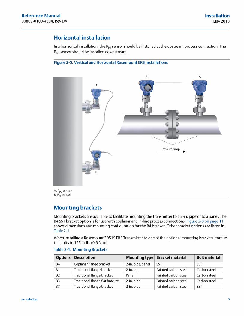
Horizontal installationIn a horizontal installation, the PHI sensor should be installed at the upstream process connection. The PLO sensor should be installed downstream.
Figure 2-5. Vertical and Horizontal Rosemount ERS Installations
A. PLO sensorB. PHI sensor
Mounting bracketsMounting brackets are available to facilitate mounting the transmitter to a 2-in. pipe or to a panel. The B4 SST bracket option is for use with coplanar and in-line process connections. Figure 2-6 on page 11 shows dimensions and mounting configuration for the B4 bracket. Other bracket options are listed in Table 2-1.
When installing a Rosemount 3051S ERS Transmitter to one of the optional mounting brackets, torque the bolts to 125 in-lb. (0,9 N-m).
Table 2-1. Mounting Brackets
Options Description Mounting type Bracket material Bolt material
B4 Coplanar flange bracket 2-in. pipe/panel SST SST
B1 Traditional flange bracket 2-in. pipe Painted carbon steel Carbon steel
B2 Traditional flange bracket Panel Painted carbon steel Carbon steel
B3 Traditional flange flat bracket 2-in. pipe Painted carbon steel Carbon steel
B7 Traditional flange bracket 2-in. pipe Painted carbon steel SST
A
B
B A
Pressure Drop
9Installation
Reference Manual00809-0100-4804, Rev DA
InstallationMay 2018
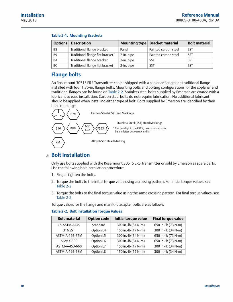
Flange boltsAn Rosemount 3051S ERS Transmitter can be shipped with a coplanar flange or a traditional flange installed with four 1.75-in. flange bolts. Mounting bolts and bolting configurations for the coplanar and traditional flanges can be found on Table 2-2. Stainless steel bolts supplied by Emerson are coated with a lubricant to ease installation. Carbon steel bolts do not require lubrication. No additional lubricant should be applied when installing either type of bolt. Bolts supplied by Emerson are identified by their head markings:
Bolt installationOnly use bolts supplied with the Rosemount 3051S ERS Transmitter or sold by Emerson as spare parts. Use the following bolt installation procedure:
1. Finger-tighten the bolts.
2. Torque the bolts to the initial torque value using a crossing pattern. For initial torque values, see Table 2-2.
3. Torque the bolts to the final torque value using the same crossing pattern. For final torque values, see Table 2-2.
Torque values for the flange and manifold adapter bolts are as follows:
Table 2-2. Bolt Installation Torque Values
B8 Traditional flange bracket Panel Painted carbon steel SST
B9 Traditional flange flat bracket 2-in. pipe Painted carbon steel SST
BA Traditional flange bracket 2-in. pipe SST SST
BC Traditional flange flat bracket 2-in. pipe SST SST
Bolt material Option code Initial torque value Final torque value
CS-ASTM-A449 Standard 300 in.-lb (34 N-m) 650 in.-lb (73 N-m)
316 SST Option L4 150 in.-lb (17 N-m) 300 in.-lb (34 N-m)
ASTM-A-193-B7M Option L5 300 in.-lb (34 N-m) 650 in.-lb (73 N-m)
Alloy K-500 Option L6 300 in.-lb (34 N-m) 650 in.-lb (73 N-m)
ASTM-A-453-660 Option L7 150 in.-lb (17 N-m) 300 in.-lb (34 N-m)
ASTM-A-193-B8M Option L8 150 in.-lb (17 N-m) 300 in.-lb (34 N-m)
Table 2-1. Mounting Brackets
Options Description Mounting type Bracket material Bolt material
Carbon Steel (CS) Head MarkingsB7M
316 B8M F
Stainless Steel (SST) Head Markings
* The last digit in the F593_ head marking may be any letter between A and M.
F593_*
KM
660 CL A
Alloy K-500 Head Marking
10 Installation

Reference Manual 00809-0100-4804, Rev DA
InstallationMay 2018
11Installation
Figure 2-6. Common Rosemount 3051S ERS Transmitter/Flange Assemblies
2.5.3 Process connectionsThe process connection size on a Rosemount 3051S ERS Transmitter flange is 1/4–18-in. NPT. Flange adapters with a 1/4–18 NPT to 1/2–14 NPT connection are available with the D2 option. Use a plant-approved lubricant or sealant when making the process connections. For other level flange type connection options, reference the Rosemount 1199 Reference Manual.
Install and tighten all four flange bolts before applying pressure to avoid leakage. When properly installed, the flange bolts will protrude through the top of the sensor module isolator plate. See Figure 2-7. Do not attempt to loosen or remove the flange bolts while the transmitter is in service.
Figure 2-7. Sensor Module Isolator Plate
A. BoltB. Sensor module isolator plateC. Coplanar flangeD. Flange adapters
Transmitter with coplanar flange
Transmitter with coplanar flange and flange adapters
Transmitter with traditional flange and flange adapters
A. 1.75 in. (44 mm) � 4B. 1.75 in. (44 mm) � 2
C. 2.88 in. (73 mm) � 2D. 1.5 in. (38 mm) �2
AB C
A D
A
B
C
D

Reference Manual00809-0100-4804, Rev DA
InstallationMay 2018
To install adapters to a coplanar flange, perform the following procedure:
1. Remove the flange bolts.
2. Leaving the flange in place, move the adapters into position with the O-rings installed.
3. Attach the adapters and the coplanar flange to the transmitter sensor module assembly using the longer of the bolts supplied.
4. Tighten the bolts. Refer to Table 2-2 on page 10 for torque specifications.
When removing flanges or adapters, visually inspect the PTFE O-rings. Replace them if there are any signs of damage such as nicks or cuts. If replacing O-rings, re-torque the flange bolts after installation to compensate for seating of the PTFE O-ring.
Impulse pipingThe piping between the process and each Rosemount 3051S ERS Transmitter must accurately transfer the pressure to obtain accurate measurements. There are many possible sources of error: pressure transfer, leaks, friction loss (particularly if purging is used), trapped gas in a liquid line, liquid in a gas line, and plugged impulse lines.
The best location for each Rosemount 3051S ERS Transmitter depends on the process itself. Use the following guidelines to determine sensor location and placement of impulse piping:
Keep impulse piping as short as possible.
For liquid service, slope the impulse piping at least 1 inch per foot (8 cm per m) upward from the transmitter toward the process connection.
For gas service, slope the impulse piping at least 1 inch per foot (8 cm per m) downward from the transmitter toward the process connection.
Avoid high points in liquid lines and low points in gas lines.
When purging, make the purge connection close to the process tap and purge through equal lengths of the same size pipe. Avoid purging through either Rosemount 3051S ERS Transmitter.
Keep corrosive or hot (above 250 °F or 121 °C) process material out of direct contact with the sensor module process connection and flanges.
Prevent sediments from depositing in the impulse piping.
NoteTake necessary steps to prevent process fluid from freezing with the process flange to avoid damage to each Rosemount 3051S ERS Transmitter.
NoteVerify the zero point on each Rosemount 3051S ERS Transmitter after installation. To reset the zero trim, refer to “Calibration overview” on page 44.
Use only the O-rings included with the flange adapter for the Rosemount 3051S ERS Transmitter. Failure to install proper fitting flange adapter O-rings may cause process leaks, which can result in death or serious injury.
12 Installation

Reference Manual 00809-0100-4804, Rev DA
InstallationMay 2018
2.5.4 Consider housing orientation
Housing rotationThe housing can be rotated to improve access to wiring or to better view the LCD display (if ordered). To rotate the housing, perform the following procedure:
1. Loosen the housing set screw.
2. Turn the housing up to 180° to the left or right of its original (as shipped) position.
NoteDo not rotate the housing more than 180° from its original position without first performing a disassembly procedure (see page 49). Over rotation may sever the electrical connection between the sensor module and the electronics feature board.
3. Retighten the housing rotation set screw.
Figure 2-8. Housing Rotation
A. Housing rotation set screw (3/32-in.)
LCD display rotationIn addition to rotating the housing, the optional LCD display on the primary Rosemount ERS Sensor can be rotated in 90° increments by squeezing the two tabs, pulling out the display, rotating, and snapping the display back into place.
NoteIf the LCD display pins are inadvertently removed from the electronics feature board, re-insert the pins before snapping the LCD display back into place.
Plantweb housing Junction box housing
AA
13Installation

Reference Manual00809-0100-4804, Rev DA
InstallationMay 2018
2.5.5 Configure security and alarm
Security switchChanges to the Rosemount ERS System configuration can be prevented with the security (write protect) switch, which is located on the electronics feature board of the Rosemount 3051S ERS Primary Transmitter. See Figure 2-9 for the location of the switch. Position the switch in the “ON” position to prevent accidental or deliberate change to the Rosemount ERS System configuration.
If the write protect switch is in the “ON” position, the Rosemount ERS System will not accept any “writes” to its memory. Configuration changes, such as digital trim and reranging, cannot take place when the security switch is set to “ON.”
Alarm directionThe alarm direction of the analog output of the Rosemount ERS System is set by repositioning the alarm switch, which is located on the electronics feature board of the primary transmitter. Position the switch in the “HI” position to have the Rosemount ERS System go to high alarm in a fail condition, or position the switch in the “LO” position to have the system go to low alarm in a fail condition. See “Alarm and saturation levels” on page 29 for more information on alarm and saturation levels.
Switch configuration procedureTo reposition the hardware switches, follow the procedure below:
1. Do not remove the housing covers in explosive atmospheres when the circuit is live. If the Rosemount 3051S ERS System is live, set the loop to manual and remove power.
2. On the Rosemount 3051S ERS Primary Transmitter, remove the housing cover opposite the field terminal side.
3. Reposition the alarm and security switches as desired, by using a small screwdriver.
4. Reinstall the housing cover. Covers must be fully engaged so the metal contacts metal in orderto meet flameproof/explosion-proof requirements.
Figure 2-9. Alarm and Security Switches
A. Security switchB. Alarm switch
BA
14 Installation

Reference Manual 00809-0100-4804, Rev DA
InstallationMay 2018
2.5.6 Connect wiring and power up
Typical Rosemount ERS System1. Remove the housing cover labeled “Field Terminals” on both Rosemount 3051S ERS Transmitter.
2. Using the Rosemount ERS Madison Cable (if ordered) or an equivalent 4-wire shielded assembly per the specifications detailed on page 16, connect the 1, 2, A, and B terminals between the two sensors per Figure 2-10. Maintain uniform twist in wires as close as possible to the screw terminals.
3. Connect the Rosemount ERS System to the control loop by wiring the “+” and “–” PWR/COMM terminals of the Rosemount 3051S ERS Primary Transmitter to the positive and negative leads, respectively.
4. Plug and seal all unused conduit connections.
5. If applicable, install wiring with a drip loop. Arrange the drip loops so the bottom is lower than the conduit connections and the transmitter housings.
6. Reinstall and tighten the housing covers on both sensors so metal contacts metal to meet explosion-proof requirements.
Rosemount 3051S ERS System with optional remote display and interface1. Remove the housing cover labeled “Field Terminals” on both Rosemount ERS Sensors and the remote
housing.
2. Using the Rosemount ERS Madison Cable (if ordered) or an equivalent 4-wire shielded assembly per the specifications detailed on page 16, connect the 1, 2, A, and B terminals between the two sensors and remote housing in a “tree” (Figure 2-11) or daisy-chain (Figure 2-12) configuration. Maintain uniform twist in wires as close as possible to the screw terminals.
3. Connect the Rosemount ERS System to the control loop by wiring the “+” and “–” PWR/COMM terminals of the remote housing to the positive and negative leads, respectively.
4. Plug and seal all unused conduit connections.
5. If applicable, install wiring with a drip loop. Arrange the drip loops so the bottom is lower than the conduit connections and the transmitter housings.
6. Reinstall and tighten all housing covers so metal contacts metal to meet explosion-proof requirements.
NoteI.S. barriers with inductive loads greater than 1 mH should not be used with the Rosemount ERS System and may cause the device to not function properly.
15Installation

Reference Manual00809-0100-4804, Rev DA
InstallationMay 2018
16 Installation
Rosemount 3051S ERS System cable specifications Cable type: Recommend gray Madison 04ZZXLF015 cable, blue Madison 04ZZXLF021 cable, and
Southwire HLX-SPOS two pairs armor cable. Other comparable cable may be used as long as it has independent dual twisted shielded pair wires with an outer shield. The power wires (pin terminals 1 and 2) must be 22 AWG minimum and the communication wires (pin terminals A and B) must be 24 AWG minimum.
Maximum cable length: The total length of cable used to connect the ERS primary transmitter, secondary transmitter, and remote display (if ordered) should not exceed maximum lengths below.
– Madison (gray cable): up to 500 ft. (152,4 m) for non-IS applications and 225 ft. (68,58 m) for IS applications; consult Emerson for applications requiring beyond 500 ft.
– Madison (blue cable): up to 225 ft. (68,58 m) for IS applications
– Armored cable: up to 125 ft. (38,1 m)
For SIS maximum lengths see “Rosemount ERS Systems safety certified identification” on page 61
Cable capacitance: The capacitance between the communication lines as wired must be less than 5000 pF total. This allows up to 50 pF per ft. (164 pF/m) for a 100-ft. cable.
Gray and blue cable outside diameter: 0.270-in. (6.86 mm)Armor cable outside diameter: 0.76-in. (19.3 mm)
For armored cable, cable glands are included with the packaging
4–20 mA loop wiring specificationsIt is recommended to use twisted pair wiring. To ensure proper communication, use 24 to 14 AWG wire, and do not exceed 5000 ft. (1500 m).
NoteThere are four connections plus shield, which require correct configuration for operation. There is no mechanism that can result in re-sequencing of messages from the physical connections.
Surges/transientsThe Rosemount 3051S ERS System will withstand electrical transients of the energy level usually encountered in static discharges or induced switching transients. However, high-energy transients, such as those induced in wiring from nearby lightning strikes, can damage the Rosemount ERS System.
Optional transient protection terminal blockThe transient protection terminal block can be ordered as an installed (option code T1) or as a spare part to retrofit an existing Rosemount ERS System in the field. A lightning bolt symbol on a terminal block identifies it as having transient protection.
NoteThe transient terminal block is only available as an option on the primary Rosemount 3051S ERS Transmitter. When ordered and installed, a primary Rosemount 3051S ERS Transmitter with the transient terminal block will protect the entire Rosemount ERS Assembly including the secondary Rosemount 3051S ERS Transmitter.
Power supply requirementsThe DC power supply should provide power with less than two percent ripple. The total loop resistance is the sum of the resistance from the signal leads and the load resistance of the controller, indicator, and related pieces. Note that the resistance of intrinsically safe barriers, if used, must be included.
Reference Manual 00809-0100-4804, Rev DA
InstallationMay 2018
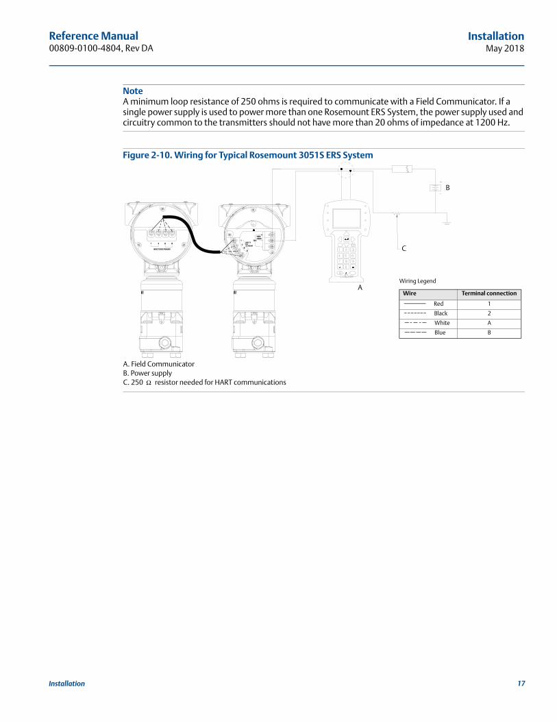
NoteA minimum loop resistance of 250 ohms is required to communicate with a Field Communicator. If a single power supply is used to power more than one Rosemount ERS System, the power supply used and circuitry common to the transmitters should not have more than 20 ohms of impedance at 1200 Hz.
Figure 2-10. Wiring for Typical Rosemount 3051S ERS System
A. Field CommunicatorB. Power supplyC. 250 resistor needed for HART communications
TEST
PWR/COMM
+_
_1 2 A B
WIRE TO ERS PRIMARY
1
2
AB
WIRE TOERSSECONDARY
A
C
B
Wiring Legend
Wire Terminal connection
Red 1
Black 2
White A
Blue B
Ω
17Installation
Reference Manual00809-0100-4804, Rev DA
InstallationMay 2018
18 Installation
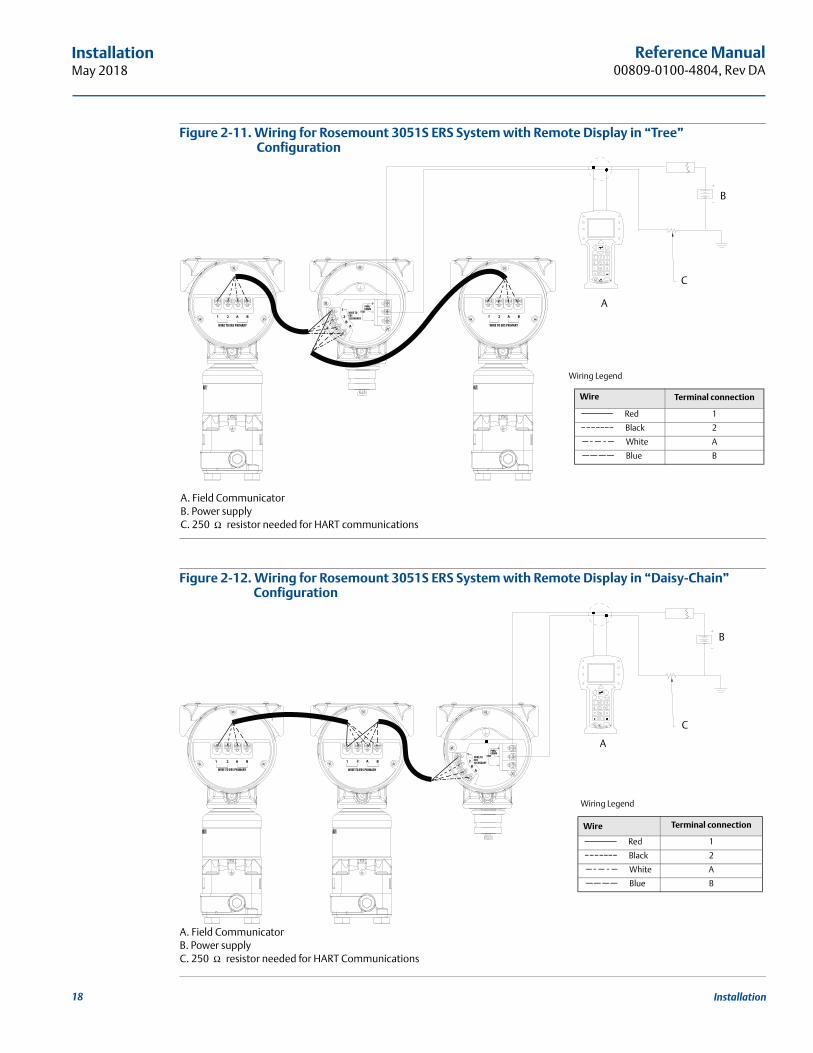
Figure 2-11. Wiring for Rosemount 3051S ERS System with Remote Display in “Tree” Configuration
A. Field CommunicatorB. Power supplyC. 250 resistor needed for HART communications
Figure 2-12. Wiring for Rosemount 3051S ERS System with Remote Display in “Daisy-Chain” Configuration
A. Field CommunicatorB. Power supplyC. 250 resistor needed for HART Communications
TEST
PWR/COMM
+_
_1 2 A B
WIRE TO ERS PRIMARY
1 2 A B
WIRE TO ERS PRIMARY
1
2
AB
WIRE TOERSSECONDARY
A
C
B
Wiring Legend
Wire Terminal connection
Red 1
Black 2
White A
Blue B
Ω
TEST
PWR/COMM
+_
_1 2 A B 1 2 A B
WIRE TO ERS PRIMARY
1
2
AB
WIRE TOERSSECONDARY
WIRE TO ERS PRIMARY
A
C
B
Wiring Legend
Wire Terminal connection
Red 1
Black 2
White A
Blue B
Ω

Reference Manual 00809-0100-4804, Rev DA
InstallationMay 2018
2.5.7 Grounding
Loop wiring groundingDo not run signal wiring in conduit or open trays with power wiring or near heavy electrical equipment. Ground the shield of the signal wiring at any one point on the signal loop. See Figure 2-13. The negative terminal of the power supply is a recommended grounding point.
NoteGrounding the transmitter case using the threaded conduit connection may not provide a sufficient ground. The transient protection terminal block (option code T1) will not provide transient protection unless the transmitter case is properly grounded. Do not run transient protection ground wire with signal wiring; the ground wire may carry excessive current if a lightning strike occurs.
Figure 2-13. Loop Wire Grounding (Rosemount 3051S ERS Primary Transmitter)
A. PositiveB. Minimize distanceC. Trim shield and insulateD. Insulate shieldE. Connect shield back to the power supply negative terminalF. Negative
B
A
F
D
E
C
19Installation
Reference Manual00809-0100-4804, Rev DA
InstallationMay 2018
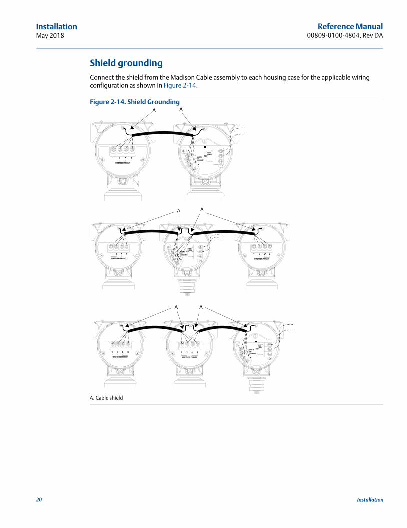
Shield groundingConnect the shield from the Madison Cable assembly to each housing case for the applicable wiring configuration as shown in Figure 2-14.
Figure 2-14. Shield Grounding
A. Cable shield
1 2 A B
WIRE TO ERS PRIMARY
1 2 A B
WIRE TO ERS PRIMARY
1
2
AB
WIRE TOERSSECONDARY
1 2 A B
WIRE TO ERS PRIMARY
1
2
AB
WIRE TOERSSECONDARY
1
2
AB
WIRE TOERSSECONDARY1 2 A B
WIRE TO ERS PRIMARY
1 2 A B
WIRE TO ERS PRIMARY
A
A
A
A
A
A
20 Installation

Reference Manual 00809-0100-4804, Rev DA
InstallationMay 2018
Transmitter caseAlways ground the transmitter case in accordance with national and local electrical codes. The most effective transmitter case grounding method is a direct connection to earth ground with minimal impedance (< 1 ohm). Methods for grounding the transmitter case include:
Internal ground connection: The internal ground connection screw is inside the terminal side of the electronics housing. The screw is identified by a ground symbol ( ), and is standard on all Rosemount 3051S ERS Transmitters.
External ground connection: The external ground connection is on the outside of the SuperModule™ housing. The connection is identified by a ground symbol ( ).
2.6 Rosemount manifoldsThe Rosemount 305 Integral Manifold assembles directly to an Rosemount 3051S ERS Transmitter, eliminating the need for the flange. The Rosemount 305 is available in two designs: coplanar (bottom process connections) and traditional (side process connections).
Figure 2-15. Rosemount 305 Integral Manifolds
The Rosemount 304 Conventional Manifold assembles directly to an instrument flange for easy servicing and retrofitting. The Rosemount 304 is available in two basic styles: traditional (flange � flange and flange � pipe) and wafer.
Figure 2-16. Rosemount 304 Conventional Manifolds
The Rosemount 306 Manifold assembles directly to an in-line style transmitter and is available with male or female 1/2-in. NPT process connections.
Coplanar Traditional
Traditional Wafer
21Installation
Reference Manual00809-0100-4804, Rev DA
InstallationMay 2018
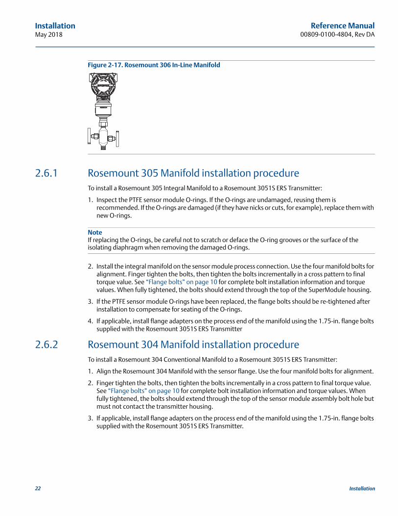
Figure 2-17. Rosemount 306 In-Line Manifold
2.6.1 Rosemount 305 Manifold installation procedureTo install a Rosemount 305 Integral Manifold to a Rosemount 3051S ERS Transmitter:
1. Inspect the PTFE sensor module O-rings. If the O-rings are undamaged, reusing them is recommended. If the O-rings are damaged (if they have nicks or cuts, for example), replace them with new O-rings.
NoteIf replacing the O-rings, be careful not to scratch or deface the O-ring grooves or the surface of the isolating diaphragm when removing the damaged O-rings.
2. Install the integral manifold on the sensor module process connection. Use the four manifold bolts for alignment. Finger tighten the bolts, then tighten the bolts incrementally in a cross pattern to final torque value. See “Flange bolts” on page 10 for complete bolt installation information and torque values. When fully tightened, the bolts should extend through the top of the SuperModule housing.
3. If the PTFE sensor module O-rings have been replaced, the flange bolts should be re-tightened after installation to compensate for seating of the O-rings.
4. If applicable, install flange adapters on the process end of the manifold using the 1.75-in. flange bolts supplied with the Rosemount 3051S ERS Transmitter
2.6.2 Rosemount 304 Manifold installation procedureTo install a Rosemount 304 Conventional Manifold to a Rosemount 3051S ERS Transmitter:
1. Align the Rosemount 304 Manifold with the sensor flange. Use the four manifold bolts for alignment.
2. Finger tighten the bolts, then tighten the bolts incrementally in a cross pattern to final torque value. See “Flange bolts” on page 10 for complete bolt installation information and torque values. When fully tightened, the bolts should extend through the top of the sensor module assembly bolt hole but must not contact the transmitter housing.
3. If applicable, install flange adapters on the process end of the manifold using the 1.75-in. flange bolts supplied with the Rosemount 3051S ERS Transmitter.
22 Installation

Reference Manual 00809-0100-4804, Rev DA
InstallationMay 2018
2.6.3 Rosemount 306 Manifold installation procedureTo install a Rosemount 306 In-Line Manifold to a Rosemount 3051S ERS Transmitter:
1. Place the Rosemount 3051S ERS Transmitter into a holding fixture.
2. Apply appropriate thread paste or tape to the threaded instrument end of the manifold.
3. Count the total threads on the manifold before starting assembly.
4. Start turning the manifold by hand into the process connection on the transmitter. Be sure the thread tape does not strip.
5. Wrench-tighten the manifold into the process connection. The minimum torque value is 425 in-lbs.
6. Count how many threads are still showing. The minimum thread engagement is three revolutions.
7. Subtract the number of threads showing (after tightening) from the total threads to calculate the revolutions engaged. Further tighten until a minimum of three rotations is achieved.
8. For block and bleed manifold, verify the bleed screw is installed and tightened. For two-valve manifold, verify the vent plug is installed and tightened.
9. Leak-check assembly to maximum pressure range of transmitter.
2.6.4 Manifold valve configurations
Block-and-bleed manifoldThe block-and-bleed configuration is available on the Rosemount 306 Manifold for use with in-line gage and absolute pressure transmitters. A single block valve provides instrument isolation, and a plug provides draining/vent capabilities.
A. TransmitterB. Bleed screwC. ProcessD. Isolate
D
B
C
A
23Installation
Reference Manual00809-0100-4804, Rev DA
InstallationMay 2018
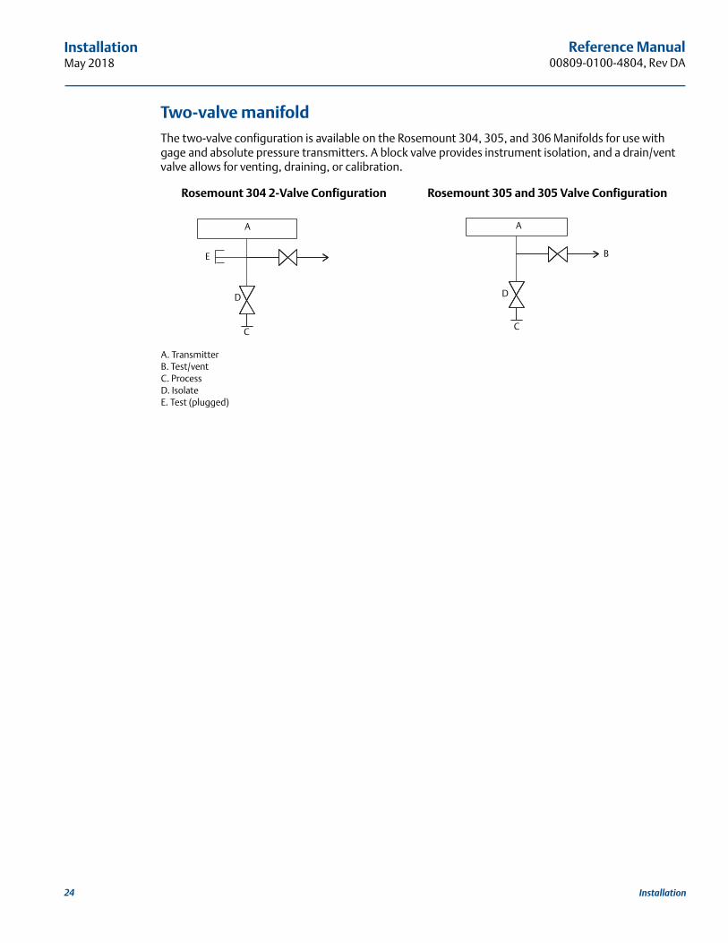
Two-valve manifoldThe two-valve configuration is available on the Rosemount 304, 305, and 306 Manifolds for use with gage and absolute pressure transmitters. A block valve provides instrument isolation, and a drain/vent valve allows for venting, draining, or calibration.
A. TransmitterB. Test/ventC. ProcessD. IsolateE. Test (plugged)
Rosemount 304 2-Valve Configuration Rosemount 305 and 305 Valve Configuration
A
D
E
C
A
B
D
C
24 Installation

Reference Manual 00809-0100-4804, Rev DA
ConfigurationMay 2018
Section 3 Configuration
Overview . . . . . . . . . . . . . . . . . . . . . . . . . . . . . . . . . . . . . . . . . . . . . . . . . . . . . . . . . . . . . . . . . . . . . . . . . . . . page 25Safety messages . . . . . . . . . . . . . . . . . . . . . . . . . . . . . . . . . . . . . . . . . . . . . . . . . . . . . . . . . . . . . . . . . . . . . . page 25Wiring diagrams . . . . . . . . . . . . . . . . . . . . . . . . . . . . . . . . . . . . . . . . . . . . . . . . . . . . . . . . . . . . . . . . . . . . . . page 26Basic setup . . . . . . . . . . . . . . . . . . . . . . . . . . . . . . . . . . . . . . . . . . . . . . . . . . . . . . . . . . . . . . . . . . . . . . . . . . . page 26Additional configuration . . . . . . . . . . . . . . . . . . . . . . . . . . . . . . . . . . . . . . . . . . . . . . . . . . . . . . . . . . . . . . . page 30HART menu trees . . . . . . . . . . . . . . . . . . . . . . . . . . . . . . . . . . . . . . . . . . . . . . . . . . . . . . . . . . . . . . . . . . . . . page 39
3.1 OverviewThis section contains information on commissioning and tasks that should be performed on the bench prior to installation.
Instructions for performing configuration functions are given for a handheld Field Communicator and AMS Device Manager version 10.5. For convenience, Field Communicator Fast Key sequences are labeled “Fast Keys” for each software function below the appropriate headings.
Example software function
3.2 Safety messagesProcedures and instructions in this section may require special precautions to ensure the safety of the personnel performing the operation. Information that raises potential safety issues is indicated with a warning symbol ( ). Refer to the following safety messages before performing an operation preceded by this symbol.
Fast Keys 1, 2, 3, etc.
Failure to follow these installation guidelines could result in death or serious injury.
Make sure only qualified personnel perform the installationExplosions could result in death or serious injury.
Do not remove the transmitter covers in explosive atmospheres when the circuit is live.
Before connecting a Field Communicator in an explosive atmosphere, make sure the instruments in the loop are installed in accordance with intrinsically safe or non-incendive field wiring practices.
Both transmitter covers must be fully engaged to meet flameproof/explosion-proof requirements.
Verify the operating atmosphere of the transmitter is consistent with the appropriate hazardous location certifications.
25Configuration

Reference Manual00809-0100-4804, Rev DA
ConfigurationMay 2018
3.2.1 Setting the loop to manualWhenever sending or requesting data that would disrupt the loop or change the output of the transmitter, set the process application loop to manual. The Field Communicator or AMS Device Manager will prompt to set the loop to manual when necessary. Acknowledging this prompt does not set the loop to manual. The prompt is only a reminder; set the loop to manual as a separate operation.
3.3 Wiring diagrams Connect a Field Communicator or AMS Device Manager using a wiring configuration as shown in Figure 2-9, Figure 2-10, or Figure 2-11. The Field Communicator or AMS Device Manager may be connected at “PWR/COMM” on the terminal block of the Rosemount 3051S ERS Primary Transmitter, across the load resistor, or at any termination point in the signal loop.
The Field Communicator or AMS Device Manager will search for a HART®-compatible device and indicate when the connection is made. If the Field Communicator or AMS Device Manager fail to connect, it indicates that no device was found. If this occurs, refer to Section 5: Troubleshooting.
3.4 Basic setupIt is recommended that the following items are verified and configured to ensure the proper functionality of the ERS System.
Electrical shock could cause death or serious injury.
If the Rosemount™ 3051S Electronic Remote Sensor (ERS)™ System is installed in a high-voltage environment and a fault or installation error occurs, high voltage may be present on the transmitter leads and terminals.
Use extreme caution when making contact with the leads and terminals.
Process leaks could result in death or serious injury.
Install and tighten all four flange bolts before applying pressure.
Do not attempt to loosen or remove flange bolts while the transmitter is in service.
Replacement equipment or spare parts not approved by Emerson™ for use as spare parts could reduce the pressure retaining capabilities of the transmitter and may render the instrument dangerous.
Use only bolts supplied or sold by Emerson as spare parts.
Improper assembly of manifolds to traditional flange can damage the device.
For the safe assembly of the manifold to the transmitter flange, bolts must break the back plane of the flange web (i.e. bolt hole) but must not contact the sensor module. Static electricity can damage sensitive components.
Observe safe handling precautions for static-sensitive components.
26 Configuration

Reference Manual 00809-0100-4804, Rev DA
ConfigurationMay 2018
3.4.1 Device tagging
TagAn 8-character free-form text field that can be used to uniquely identify the device.
Long tagA 32-character free-form text field that can be used to uniquely identify the device. Long tag is only supported by host systems that are HART Revision 6 or higher.
DescriptorA 16-character free-form text field that can be used to further describe the device or application.
MessageA 32-character free-form text field that can be used to save a message or memo about the device or application.
DateA formatted field (mm/dd/yyyy) available to enter and store a date (such as the day of installation or last calibration).
3.4.2 Units of measure
The Differential Pressure, PHI Pressure, and PLO Pressure measurements can be independently configured for any of the units shown in Table 3-1.
The PHI and PLO Module Temperatures can be independently configured for Fahrenheit or Celsius.
Table 3-1. Pressure Units of Measure
3.4.3 Damping
The damping software feature introduces a delay in processing which increases the response time of the measurement, smoothing variations in output readings caused by rapid input changes. Determine the appropriate damping setting based on the necessary response time, signal stability, and other requirements of your application.
Damping can be set independently for the Differential Pressure, PHI Pressure, and PLO Pressure measurements. Damping values can be set anywhere from 0 to 60 seconds.
Fast Keys 2, 1, 1, 1
Fast Keys 2, 1, 1, 2, 1
inH2O at 68 °F bar Torr
inHg at 0 °C mbar Atm
ftH2O at 68 °F g/cm2 MPa
mmH2O at 68 °F kg/cm2 inH2O at 4 °C
mmHg at 0 °C Pa mmH2O at 4 °C
Psi kPa in H2O at 60 °F
Fast Keys 2, 1, 1, 2, 2
27Configuration

Reference Manual00809-0100-4804, Rev DA
ConfigurationMay 2018
3.4.4 Variable mapping
Select which ERS System parameters to assign to each HART variable.
Primary variableThe parameter assigned to the HART Primary Variable controls the 4–20 mA Analog Output. The following ERS System parameters can be assigned to the Primary Variable:
Differential pressure
PHI Pressure
PLO Pressure
Scaled Variable
2nd, 3rd, and 4th variables
The 2nd, 3rd, and 4th variables can be accessed digitally through a HART host. A HART-to-Analog converter, such as the Rosemount 333 Tri-Loop™, can also be used to convert each of the variables to a separate 4–20 mA analog output signal. These variables can also be accessed wirelessly by using an Emerson Wireless THUM™ Adapter. The following ERS System parameters can be assigned to the 2nd, 3rd, and 4th variables:
Differential Pressure
PHI Pressure
PLO Pressure
PHI Module Temperature
PLO Module Temperature
Scaled Variable
3.4.5 Analog output
Configure the lower and upper range values, which correspond to the 4 and 20 mA analog output range points. The 4 mA point represents the zero percent of span reading, and the 20 mA point represents the 100% of span reading.
The analog output range points can also be set using the zero and span adjustment buttons located on the electronics of the Rosemount 3051S ERS Primary Transmitter (see Figure 3-1) and a pressure source.
1. Using a pressure source with an accuracy three to ten times the desired calibrated accuracy, apply a pressure equivalent to the lower range value to the PHI transmitter.
2. Push and hold the zero adjustment button for at least two seconds but no longer than 10 seconds.
3. Apply a pressure equivalent to the upper range value to the PHI transmitter.
4. Push and hold the span adjustment button for at least two seconds but no longer than 10 seconds.
Fast Keys 2, 1, 1, 3
Fast Keys 2, 1, 1, 4
28 Configuration
Reference Manual 00809-0100-4804, Rev DA
ConfigurationMay 2018
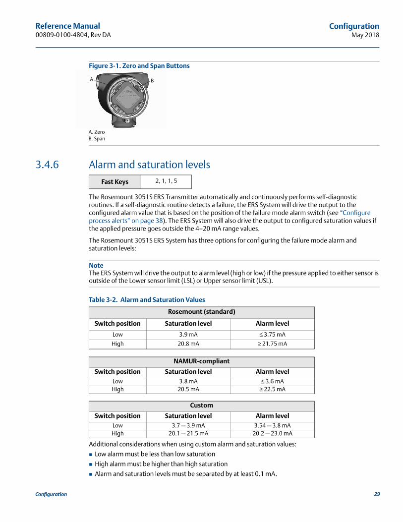
Figure 3-1. Zero and Span Buttons
A. ZeroB. Span
3.4.6 Alarm and saturation levels
The Rosemount 3051S ERS Transmitter automatically and continuously performs self-diagnostic routines. If a self-diagnostic routine detects a failure, the ERS System will drive the output to the configured alarm value that is based on the position of the failure mode alarm switch (see “Configure process alerts” on page 38). The ERS System will also drive the output to configured saturation values if the applied pressure goes outside the 4–20 mA range values.
The Rosemount 3051S ERS System has three options for configuring the failure mode alarm and saturation levels:
NoteThe ERS System will drive the output to alarm level (high or low) if the pressure applied to either sensor is outside of the Lower sensor limit (LSL) or Upper sensor limit (USL).
Table 3-2. Alarm and Saturation Values
Additional considerations when using custom alarm and saturation values:
Low alarm must be less than low saturation
High alarm must be higher than high saturation
Alarm and saturation levels must be separated by at least 0.1 mA.
Fast Keys 2, 1, 1, 5
Rosemount (standard)
Switch position Saturation level Alarm level
Low 3.9 mA ≤ 3.75 mA
High 20.8 mA ≥ 21.75 mA
NAMUR-compliant
Switch position Saturation level Alarm levelLow 3.8 mA ≤ 3.6 mAHigh 20.5 mA ≥ 22.5 mA
Custom
Switch position Saturation level Alarm levelLow 3.7 — 3.9 mA 3.54 — 3.8 mAHigh 20.1 — 21.5 mA 20.2 — 23.0 mA
BA
29Configuration

Reference Manual00809-0100-4804, Rev DA
ConfigurationMay 2018
3.5 Additional configurationThe following items are considered optional and may be configured as needed. Refer to Figure 3-7 on page 39 for the full Field Communicator menu tree.
3.5.1 Local display
A local display is available as an orderable option on the Rosemount 3051S ERS Primary Transmitter. The display will show a 0–100 percent scaled bar graph, the selected measurements from Table 3-3, and any diagnostic or error messages. At least one parameter from Table 3-3 must be selected. If more than one item is selected, the display will scroll through the selected parameters, showing each for three seconds.
Table 3-3. Available Parameters for Local Display
3.5.2 Burst mode
When configured for burst mode, ERS provides faster digital communication from the ERS System to the control system by eliminating the time required for the control system to request information from the ERS System.
When in burst mode, the ERS System will continue to output a 4–20 mA analog signal. Because the HART protocol features simultaneous digital and analog data transmission, the analog value can drive other equipment in the loop while the control system is receiving the digital information. Burst mode applies only to the transmission of dynamic data (process variables in engineering units, primary variable in percent of span, and the analog output reading), and does not affect the way other transmitter data is accessed.
Access to information that is not burst can be obtained through the normal poll/response method of HART communication. A Field Communicator, AMS Device Manager, or the control system may request any of the information that is normally available while the ERS System is in burst mode.
Burst mode configurationTo have the ERS System configured to communicate in burst mode:
1. Set the Burst Mode parameter to “on.”
2. Select a Burst Option from Table 3-4 below. This parameter determines what information is communicated through burst mode.
Table 3-4. Burst Command Options
Fast Keys 2, 1, 3
Differential pressure PHI module temperature Output (% of range)
PHI pressure PLO module temperature N/A
PLO pressure Scaled variable N/A
Fast Keys 2, 2, 5, 3
HART command Burst option Description
1 PV Primary Variable
2 % range/current Percent of range and mA output
3 Dyn vars/current All process variables and mA output
9 Devices vars w/status Burst variables and status information
33 Device variables Burst variables
30 Configuration

Reference Manual 00809-0100-4804, Rev DA
ConfigurationMay 2018
31Configuration
NoteIf using an ERS System with the Rosemount 333 HART Tri-Loop, the burst option should be set to “Dyn vars/current.”
Burst variable slot definitionIf either Device vars w/status or Device Variables is selected as the Burst Option, you will need to configure which variables are communicated in Burst Mode. This is accomplished by assigning a variable to a Burst Slot. ERS System has four available Burst Slots for burst communication.
3.5.3 Multidrop communication
The HART protocol allows several transmitters to communicate digitally on a single transmission line when wired in a Multidrop network. If using an ERS System in a multidrop network, the connection to the network is made through the primary sensor as shown in Figure 3-2.
NoteFigure 3-2 shows a typical multidrop network. This figure is not intended as an installation diagram.
Communication between the host and the transmitters takes place digitally, and the analog output on each transmitter is deactivated.
NoteA transmitter in multidrop mode with “Loop Current Mode” disabled has the analog output fixed at 4 mA.
Figure 3-2. Typical Multidrop Network
A. HART modemB. Power supplyC. ERS System
Fast Keys 2, 2, 5, 2
A
B
C

Reference Manual00809-0100-4804, Rev DA
ConfigurationMay 2018
Enabling multidrop configurationTo configure an ERS System to be part of a multidrop network:
1. Assign a unique address to the ERS System. For a HART Revision 5 system, the valid address range is 1–15. For systems that are HART Revision 6 or above, the valid address range is 1-63. All Rosemount transmitters are shipped from the factory with the default address of zero (0).
2. Disable “Loop Current Mode.” This will cause the analog output of the ERS System to be fixed at 4 mA.
NoteWhen an ERS System is configured for multidrop communication, a failure or alarm condition will no longer be indicated through the analog output. Failure signals in multidropped transmitters are communicated digitally through HART messages.
Disabling multidrop configurationTo configure an ERS System with the factory default point-to-point communication:
1. Assign the ERS System with an address of zero (0).
2. Enable “Loop Current Mode.”
3.5.4 Scaled variable
Scaled variable can be used to convert the Differential Pressure (DP) that is calculated by the ERS System into an alternative measurement such as level, mass, or volume. For example, an ERS System that measures 0–500 mbar of DP can be configured to output a level measurement of 0–5 m. The Scaled Variable calculation can be shown on the LCD display and can also be assigned to the 4–20 mA output.
Anywhere from two to 20 points can be used to define the mathematical relationship between the measured DP and the calculated scaled variable.
Configuring scaled variable to calculate level
Because level can be linearly derived from DP, only two scaled variable points are required to configure ERS to calculate a Level measurement. The steps required to configure scaled variable for a Level application are highlighted below:
1. Enter in a text string (up to five characters: A–Z, -, %, /, *, and “space”) to define the unit of measure for the scaled output. Examples include METER, FEET, or INCH.
2. Enter the minimum DP (in engineering units) that the ERS System will measure. This value will usually be zero (0).
3. Enter the scaled variable value (in terms of the scaled units defined in Step 1) that corresponds to the minimum DP from Step 2.
4. Enter the maximum DP that the ERS System will measure.
5. Enter the scaled variable value that corresponds to the DP from Step 4.
6. To have the 4–20 mA signal of the ERS System output the scaled variable measurement, map scaled variable to the HART Primary Variable and configure the upper and lower range values.
Fast Keys 2, 2, 3
Fast Keys 2, 2, 3, 5, 1
32 Configuration
Reference Manual 00809-0100-4804, Rev DA
ConfigurationMay 2018
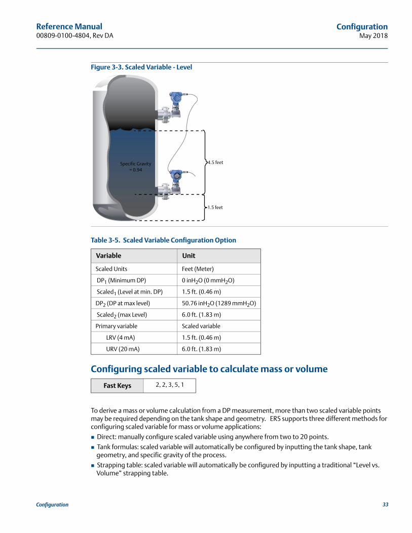
Figure 3-3. Scaled Variable - Level
Configuring scaled variable to calculate mass or volume
To derive a mass or volume calculation from a DP measurement, more than two scaled variable points may be required depending on the tank shape and geometry. ERS supports three different methods for configuring scaled variable for mass or volume applications:
Direct: manually configure scaled variable using anywhere from two to 20 points.
Tank formulas: scaled variable will automatically be configured by inputting the tank shape, tank geometry, and specific gravity of the process.
Strapping table: scaled variable will automatically be configured by inputting a traditional “Level vs. Volume” strapping table.
Table 3-5. Scaled Variable Configuration Option
Variable Unit
Scaled Units Feet (Meter)
DP1 (Minimum DP) 0 inH2O (0 mmH2O)
Scaled1 (Level at min. DP) 1.5 ft. (0.46 m)
DP2 (DP at max level) 50.76 inH2O (1289 mmH2O)
Scaled2 (max Level) 6.0 ft. (1.83 m)
Primary variable Scaled variable
LRV (4 mA) 1.5 ft. (0.46 m)
URV (20 mA) 6.0 ft. (1.83 m)
Fast Keys 2, 2, 3, 5, 1
Specific Gravity= 0.94
4.5 feet
1.5 feet
33Configuration
Reference Manual00809-0100-4804, Rev DA
ConfigurationMay 2018
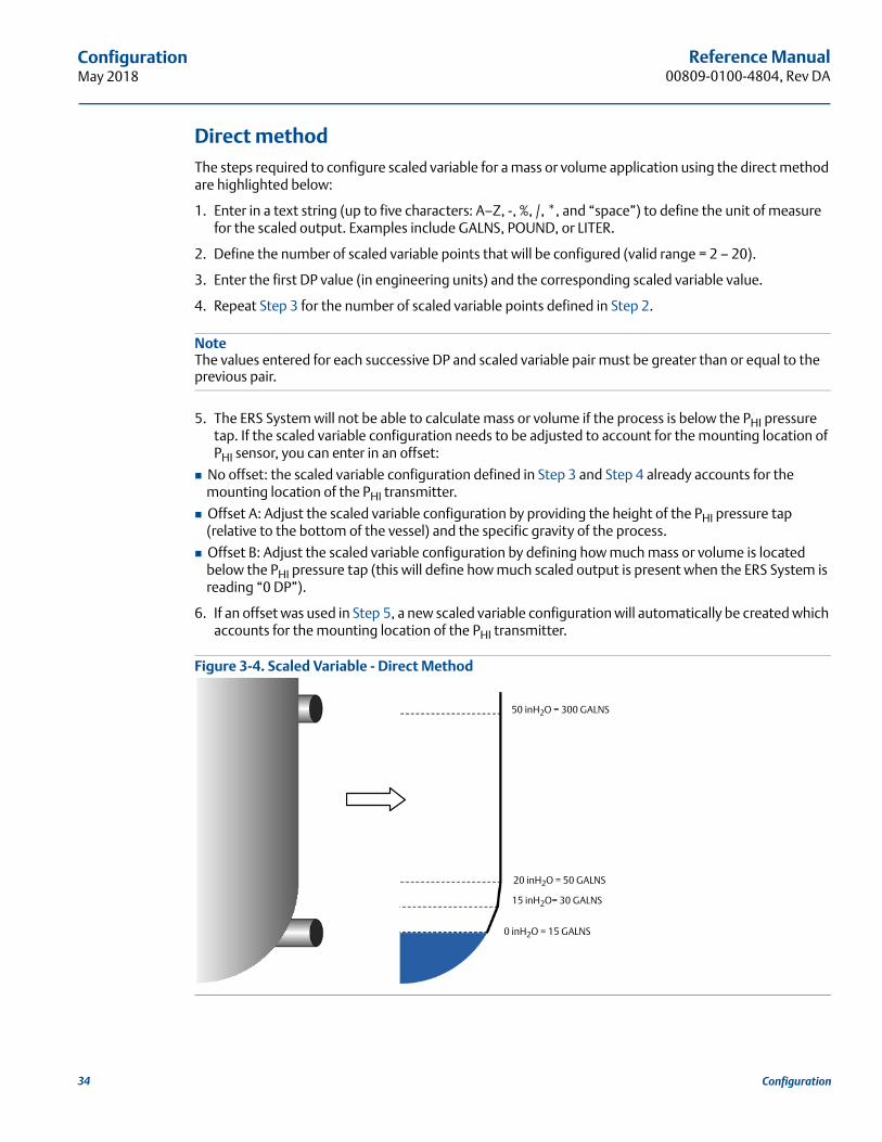
Direct methodThe steps required to configure scaled variable for a mass or volume application using the direct method are highlighted below:
1. Enter in a text string (up to five characters: A–Z, -, %, /, *, and “space”) to define the unit of measure for the scaled output. Examples include GALNS, POUND, or LITER.
2. Define the number of scaled variable points that will be configured (valid range = 2 – 20).
3. Enter the first DP value (in engineering units) and the corresponding scaled variable value.
4. Repeat Step 3 for the number of scaled variable points defined in Step 2.
NoteThe values entered for each successive DP and scaled variable pair must be greater than or equal to the previous pair.
5. The ERS System will not be able to calculate mass or volume if the process is below the PHI pressure tap. If the scaled variable configuration needs to be adjusted to account for the mounting location of PHI sensor, you can enter in an offset:
No offset: the scaled variable configuration defined in Step 3 and Step 4 already accounts for the mounting location of the PHI transmitter.
Offset A: Adjust the scaled variable configuration by providing the height of the PHI pressure tap (relative to the bottom of the vessel) and the specific gravity of the process.
Offset B: Adjust the scaled variable configuration by defining how much mass or volume is located below the PHI pressure tap (this will define how much scaled output is present when the ERS System is reading “0 DP”).
6. If an offset was used in Step 5, a new scaled variable configuration will automatically be created which accounts for the mounting location of the PHI transmitter.
Figure 3-4. Scaled Variable - Direct Method
50 inH2O = 300 GALNS
20 inH2O = 50 GALNS
15 inH2O= 30 GALNS
0 inH2O = 15 GALNS
34 Configuration
Reference Manual 00809-0100-4804, Rev DA
ConfigurationMay 2018
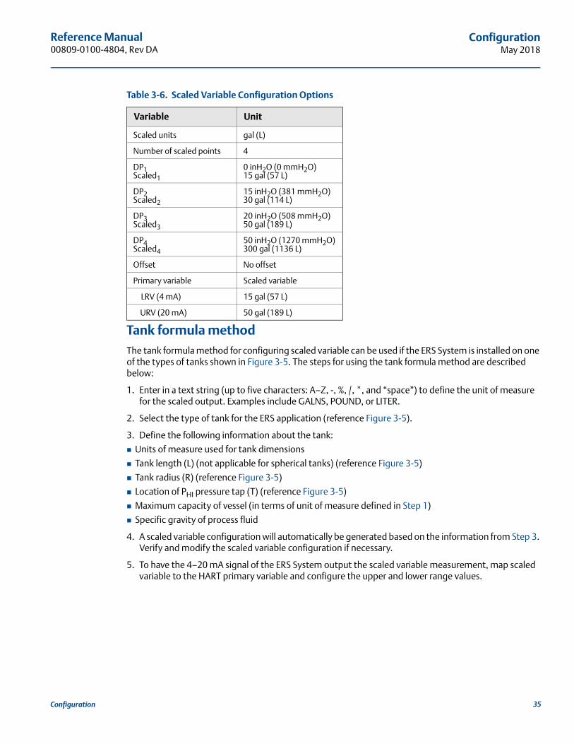
Tank formula methodThe tank formula method for configuring scaled variable can be used if the ERS System is installed on one of the types of tanks shown in Figure 3-5. The steps for using the tank formula method are described below:
1. Enter in a text string (up to five characters: A–Z, -, %, /, *, and “space”) to define the unit of measure for the scaled output. Examples include GALNS, POUND, or LITER.
2. Select the type of tank for the ERS application (reference Figure 3-5).
3. Define the following information about the tank:
Units of measure used for tank dimensions
Tank length (L) (not applicable for spherical tanks) (reference Figure 3-5)
Tank radius (R) (reference Figure 3-5)
Location of PHI pressure tap (T) (reference Figure 3-5)
Maximum capacity of vessel (in terms of unit of measure defined in Step 1)
Specific gravity of process fluid
4. A scaled variable configuration will automatically be generated based on the information from Step 3. Verify and modify the scaled variable configuration if necessary.
5. To have the 4–20 mA signal of the ERS System output the scaled variable measurement, map scaled variable to the HART primary variable and configure the upper and lower range values.
Table 3-6. Scaled Variable Configuration Options
Variable Unit
Scaled units gal (L)
Number of scaled points 4
DP1 Scaled1
0 inH2O (0 mmH2O)15 gal (57 L)
DP2 Scaled2
15 inH2O (381 mmH2O)30 gal (114 L)
DP3Scaled3
20 inH2O (508 mmH2O)50 gal (189 L)
DP4Scaled4
50 inH2O (1270 mmH2O)300 gal (1136 L)
Offset No offset
Primary variable Scaled variable
LRV (4 mA) 15 gal (57 L)
URV (20 mA) 50 gal (189 L)
35Configuration
Reference Manual00809-0100-4804, Rev DA
ConfigurationMay 2018
36 Configuration
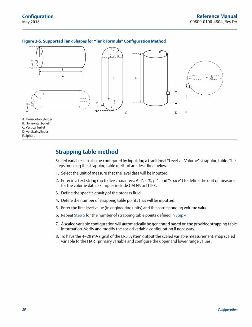
Figure 3-5. Supported Tank Shapes for “Tank Formula” Configuration Method
A. Horizontal cylinderB. Horizontal bulletC. Vertical bulletD. Vertical cylinderE. Sphere
Strapping table methodScaled variable can also be configured by inputting a traditional “Level vs. Volume” strapping table. The steps for using the strapping table method are described below:
1. Select the unit of measure that the level data will be inputted.
2. Enter in a text string (up to five characters: A–Z, -, %, /, *, and “space”) to define the unit of measure for the volume data. Examples include GALNS or LITER.
3. Define the specific gravity of the process fluid.
4. Define the number of strapping table points that will be inputted.
5. Enter the first level value (in engineering units) and the corresponding volume value.
6. Repeat Step 5 for the number of strapping table points defined in Step 4.
7. A scaled variable configuration will automatically be generated based on the provided strapping table information. Verify and modify the scaled variable configuration if necessary.
8. To have the 4–20 mA signal of the ERS System output the scaled variable measurement, map scaled variable to the HART primary variable and configure the upper and lower range values.
A
B C D E
R
R
RR
R
T
T
LL
TT
L
L
T

Reference Manual 00809-0100-4804, Rev DA
ConfigurationMay 2018
37Configuration
3.5.5 Module assignments
The ERS System calculates DP by taking the pressure measurement from the PHI transmitter and subtracting the pressure measurement from the PLO transmitter.
Rosemount 3051S ERS Transmitters are shipped from the factory preconfigured so the primary sensor (4–20 loop termination and optional LCD display) is assigned as the PHI device, and the secondary sensor (junction box housing) is assigned as the PLO device. In installations where the primary transmitter is installed on the PLO process connection (such as at the top of a tank), these designations may be switched electronically using a Field Communicator.
Change the PHI and PLO module assignments1. View the neck label on each Rosemount 3051S ERS Transmitter and note the serial number and
pressure location (PHI vs. PLO) of the transmitter.
2. Using a Field Communicator, view the serial number and the assigned pressure location for either “Module 1” or “Module 2”.
3. If the currently assigned PHI/PLO designations do not reflect the actual installation as recorded from Step 1, change the PHI/PLO assignments using either of the following commands:
Set Module 1 = PHI, Module 2 = PLO
Set Module 1 = PLO, Module 2 = PHI
View the DP measurement from the ERS System and verify the calculation is of positive magnitude. If the DP measurement is of negative magnitude, use the other module assignment command from Step 3.
Figure 3-6. Example of How to Change the PHI and PLO Module Assignments
Fast Keys 2, 2, 6
PLO SensorSerial Number 11223344
DP = PHI - PLO
PHI SensorSerial Number 44332211
12
3
Reference Manual00809-0100-4804, Rev DA
ConfigurationMay 2018
3.5.6 Process alerts
Process alerts allow for the configuration of the ERS System to output a HART message when a parameter (such as the measured DP) exceeds a user-defined operating window. An alert will be communicated to the HART host (such as a Field Communicator or AMS Device Manager) when polled, and on the LCD display of the ERS System. The alert will reset once the value returns within range.
Process alerts may be configured for the following parameters:
Differential pressure
PHI pressure
PLO pressure
PHI module temperature
PLO module temperature
Configure process alerts1. Select a parameter for which the process alert will be configured.
2. Set the Alert Mode to “enable.”
3. Define the low alert value. If the measured value for the parameter goes below the low alert value, an alert message will be generated.
4. Define the high alert value. if the measured value for the parameter goes above the high alert value, an alert message will be generated.
Disable process alerts1. Select a parameter for which the process alert will be disabled.
2. Set the Alert Mode to “disabled”.
Fast Keys 2, 3
38 Configuration
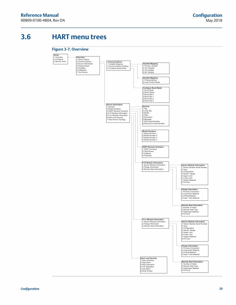
Reference Manual 00809-0100-4804, Rev DA
ConfigurationMay 2018
39Configuration
3.6 HART menu trees
Figure 3-7. OverviewHome1 Overview2 Configure3 Service Tools
Overview1 Device Status2 Communications3 Device Information4 Analog Output5 Variables6 Calibration7 Find Device
Communications1 Variable Mapping2 Communications Setting3 Configure Burst Mode
Variable Mapping1 Primary Variable2 2nd Variable3 3rd Variable4 4th Variable
Variable Mapping1 Polling Address2 Loop Current Mode
Configure Burst Mode1 Burst Mode2 Burst Option3 Burst Slot 04 Burst Slot 15 Burst Slot 26 Burst Slot 3
Device Information1 General2 Model Numbers3 HART Revision Numbers4 P-Hi Module Information5 P-Lo Module Information6 Alarm and Security7 View Device Topology
General1 Tag2 Long Tag3 Model4 Date5 Descriptor6 Message7 ERS Serial Number8 Electronics Serial Number
Model Numbers1 Model Number 12 Model Number 23 Model Number 34 Model Number 4
HART Revision Numbers1 HART Universal2 Field Device3 Software4 Hardware
P-Hi Module Information1 Sensor Module Information2 Flange Information3 Remote Seal Information
Sensor Module Information1 Sensor Module Serial Number2 Type3 Configuration4 Sensor Range5 Upper Limit6 Lower Limit7 Isolator Material8 Fill Fluid
Flange Information1 Process Connection2 Connection Material3 O-Ring Material4 Drain / Vent Material
Remote Seal Information1 Number of Seals2 Remote Seal Type3 Diaphragm Material4 Fill Fluid
P-Lo Module Information1 Sensor Module Information2 Flange Information3 Remote Seal Information
Sensor Module Information1 Sensor Module Serial Number2 Type3 Configuration4 Sensor Range5 Upper Limit6 Lower Limit7 Isolator Material8 Fill Fluid
Flange Information1 Process Connection2 Connection Material3 O-Ring Material4 Drain / Vent Material
Remote Seal Information1 Number of Seals2 Remote Seal Type3 Diaphragm Material4 Fill Fluid
Alarm and Security1 Alarm Direction2 High Alarm3 High Saturation4 Low Saturation5 Low Alarm6 Write Protect
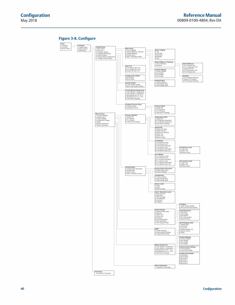
40
Reference Manual00809-0100-4804, Rev DA
ConfigurationMay 2018
Figure 3-8. ConfigureHome1 Overview2 Configure3 Service Tools
Guided Setup1 Basic Setup2 Zero Trim3 Configure Display4 Configure Burst Mode5 Scaled Variable6 Change Module Assignments7 Configure Process Alerts
Basic Setup1 Device Tagging2 Units of Measure / Damping3 Variable Mapping4 Analog Output5 Alarm / Saturation Levels
Configure1 Guided Setup2 Manual Setup3 Alert Setup Device Tagging
1 Tag2 Long Tag3 Descriptor4 Message5 Date
Units of Measure / Damping1 Units of Measure2 Damping
Units of Measure1 P-Lo Pressure Unit2 P-Lo Temperature Unit3 System DP Unit4 P-Hi Temperature Unit5 P-Hi Pressure Unit
Damping1 P-Lo Pressure Damping2 System DP Damping3 P-Hi Pressure Damping
Variable Mapping1 Primary Variable2 2nd Variable3 3rd Variable4 4th Variable
Analog Output1 Primary Variable2 Upper Range Value3 Lower Range Value
Zero Trim1 P-Hi Sensor Zero Trim2 P-Lo Sensor Zero Trim3 System DP Zero Trim
Configure Burst Mode1 Burst Mode2 Burst Option
Scaled Variable1 Linear Scaled Variable2 Non-Linear Scaled Variable
Change Module Assignments1 View "Module 1" Assignment2 View "Module 2" Assignment3 Set Modules as P-Hi - P-Lo4 Set Modules as P-Lo - P-Hi5 View Device Topology
Configure Process Alerts1 Pressure Alerts2 Temperature Alerts
Pressure Alerts1 System DP2 P-Hi Pressure3 P-Lo Pressure4 View Device Topology
Temperature Alerts1 System DP2 P-Hi Module Temperature3 P-Lo Module Temperature4 View Device Topology
Manual Setup1 Process Variables2 Analog Output3 Scaled Variable4 Configuration Display5 HART6 Module Assignment7 Device Information
Process Variables1 System DP2 P-Hi Module3 P-Lo Module4 View Device Topology
System DP1 System DP Value2 System DP Unit3 System DP Damping4 Upper Limit5 Lower Limit6 Minimum Span
P-Hi Module1 P-Hi Pressure Value2 P-Hi Pressure Unit3 P-Hi Pressure Damping4 P-Hi Sensor Limits5 P-Hi Module Temperature6 P-Hi Module Temp. Unit
P-Hi Sensor Limits1 Upper Limit2 Lower Limit3 Minimum Span
P-Lo Module1 P-Lo Pressure Value2 P-Lo Pressure Unit3 P-Lo Pressure Damping4 P-Lo Sensor Limits5 P-Lo Module Temperature6 P-Lo Module Temp. Unit
P-Lo Sensor Limits1 Upper Limit2 Lower Limit3 Minimum Span
Analog Output1 Analog Output Information2 Configuration3 Sensor Limits4 Alarm / Saturation Levels
Analog Output Information1 Analog Output Value2 Percent of Range
Configuration1 Primary Variable2 Upper Range Value3 Lower Range Value
Sensor Limits1 Upper2 Lower3 Minimum Span
Alarm / Saturation Levels1 Alarm Direction2 High Alarm3 High Saturation4 Low Saturation5 Low Alarm6 Configure
Scaled Variable1 Scaled Variable Value2 Damping3 Upper Limit4 Lower Limit5 Configure6 View Configuration7 Tank Dimensions8 View Strapping Table
Configure1 Linear Scaled Variable2 Non-Linear Scaled Variable
Tank Dimensions1 Tank Type2 Tank Length3 Tank Radius4 P-Hi Tap Location5 Specific Gravity
View Strapping Table1 Update Table2 View Table3 Level Unit4 Scaled Variable Unit5 Specific Gravity6 Offset
HART1 Variable Mapping2 Communication Settings3 Configure Burst Mode
Variable Mapping1 Primary Variable2 2nd Variable3 3rd Variable4 4th Variable
Communication Settings1 Polling Address2 Loop Current Mode
Configure Burst Mode1 Burst Mode2 Burst Option3 Burst Slot 04 Burst Slot 15 Burst Slot 26 Burst Slot 3
Module Assignment1 View “Module 1” Assignment2 View “Module 2” Assignment3 Set Modules as P-Hi – P-Lo4 Set Modules as P-Lo – P-Hi5 View Device Topology
Device Information Continued on next page...
Alert Setup Continued on next page...
Configuration

Reference Manual 00809-0100-4804, Rev DA
ConfigurationMay 2018
Figure 3-9. Alert Setup, Device Information, and Service Tools
Home1 Overview2 Configure3 Service Tools
Service Tools1 Device Alerts2 Variables3 Trends4 Maintenance5 Simulate
Variables1 System DP2 P-Hi Pressure3 P-Lo Pressure4 P-Hi Module Temperature5 P-Lo Module Temperature6 Scaled Variable
Trends1 System DP2 P-Hi Pressure3 P-Lo Pressure4 P-Hi Module Temperature5 P-Lo Module Temperature6 Scaled Variable
Maintenance1 Analog Calibration2 System DP Calibration3 P-Hi Calibration4 P-Lo Calibration5 Find Device
Analog Calibration1 Analog Trim2 Restore Factory Calibration3 Analog Output Value4 Percent of Range5 Primary Variable6 Upper Range Value7 Lower Range Value
System DP Calibration1 System DP Trim2 Restore Factory Calibration3 View Last Trim4 View DP Limits5 System DP Value6 Data Quality7 Status8 Damping
P-Hi Calibration1 P-Hi Sensor Trim2 Restore Factory Calibration3 View Last Trim4 View P-Hi Sensor Limits5 P-Hi Pressure Value6 Data Quality7 Status8 Damping
P-Lo Calibration1 P-Lo Sensor Trim2 Restore Factory Calibration3 View Last Trim4 View P-Hi Sensor Limits5 P-Lo Pressure Value6 Data Quality7 Status8 Damping
P-Lo Sensor Trim1 Upper Trim2 Lower Trim3 Zero Trim4 Calibration Type
View Last Trim1 Last Upper Trim2 Last Lower Trim
View P-Lo Sensor Limits1 Upper Limit2 Lower Limit3 Minimum Span
P-Lo Sensor Trim1 Upper Trim2 Lower Trim3 Zero Trim4 Calibration Type
View Last Trim1 Last Upper Trim2 Last Lower Trim
View P-Hi Sensor Limits1 Upper Limit2 Lower Limit3 Minimum Span
Simulate1 Loop Test
Device Information1 General2 Model Numbers3 HART Revision Numbers4 P-Hi Module Information5 P-Lo Module Information6 Alarm and Security7. View Device Topology
Alert Setup1 Pressure Alerts2 Temperature Alerts3 View Device Topology
Pressure Alerts1 System DP2 P-Hi Pressure3 P-Lo Pressure4 View Device Topology
Temperature Alerts1 System DP2 P-Hi Module Temperature3 P-Lo Module Temperature4 View Device Topology
General1 Tag2 Long Tag3 Model4 Date5 Descriptor6 Message7 ERS Serial Number
Model Numbers1 Model Number 12 Model Number 23 Model Number 34 Model Number 4
HART Revision Numbers1 HART Universal2 Field Device3 Software4 Hardware
P-Hi Module Information1 Sensor Module Information2 Flange Information3 Remote Seal Information
P-Lo Module Information1 Sensor Module Information2 Flange Information3 Remote Seal Information
Sensor Module Information1 Sensor Module Serial Number2. Type3 Configuration4 Sensor Range5 Upper Limit6 Lower Limit7 Isolator Material8 Fill Fluid
Flange Information1 Process Connection2 Connection Material3 O-Ring Material4 Drain / Vent Material
Remote Seal Information1 Number of Seals2 Remote Seal Type3 Diaphragm Material4. Fill Fluid
Alarm and Security1 Alarm Direction2 High Alarm3 High Saturation4 Low Saturation5 Low Alarm6 Write Protect
Configure1 Guided Setup2 Manual Setup3 Alert Setup
Manual Setup1 Process Variables2 Analog Output3 Scaled Variable4 Configuration Display5 HART6 Module Assignment7 Device Information
41Configuration

42
Reference Manual00809-0100-4804, Rev DA
ConfigurationMay 2018
Configuration

Reference Manual 00809-0100-4804, Rev DA
Operation and MaintenanceMay 2018
Section 4 Operation and Maintenance
Overview . . . . . . . . . . . . . . . . . . . . . . . . . . . . . . . . . . . . . . . . . . . . . . . . . . . . . . . . . . . . . . . . . . . . . . . . . . . . page 43Safety messages . . . . . . . . . . . . . . . . . . . . . . . . . . . . . . . . . . . . . . . . . . . . . . . . . . . . . . . . . . . . . . . . . . . . . . page 43Calibration . . . . . . . . . . . . . . . . . . . . . . . . . . . . . . . . . . . . . . . . . . . . . . . . . . . . . . . . . . . . . . . . . . . . . . . . . . . page 44Functional tests . . . . . . . . . . . . . . . . . . . . . . . . . . . . . . . . . . . . . . . . . . . . . . . . . . . . . . . . . . . . . . . . . . . . . . page 48Field upgrades and replacements . . . . . . . . . . . . . . . . . . . . . . . . . . . . . . . . . . . . . . . . . . . . . . . . . . . . . . . page 49
4.1 OverviewThis section contains information on commissioning and operating a Rosemount™ 3051S Electronic Remote Sensor (ERS)™ System.
Instructions for performing operation and maintenance functions are given for a handheld Field Communicator. For convenience, Field Communicator Fast Key sequences are labeled “Fast Keys” for each software function below the appropriate headings.
Example software function
4.2 Safety messagesProcedures and instructions in this section may require special precautions to ensure the safety of the personnel performing the operation. Information that raises potential safety issues is indicated with a warning symbol ( ). Refer to the following safety messages before performing an operation preceded by this symbol.
Fast Keys 1, 2, 3, etc.
Failure to follow these installation guidelines could result in death or serious injury.
Make sure only qualified personnel perform the installation.Explosions could result in death or serious injury.
Do not remove the transmitter covers in explosive atmospheres when the circuit is live.
Before connecting a Field Communicator in an explosive atmosphere, make sure the instruments in the loop are installed in accordance with intrinsically safe or non-incendive field wiring practices.
Both transmitter covers must be fully engaged to meet flameproof/explosion-proof requirements.
Verify the operating atmosphere of the transmitter is consistent with the appropriate hazardous location certifications.
43Operation and Maintenance

Reference Manual00809-0100-4804, Rev DA
Operation and MaintenanceMay 2018
4.3 Calibration
4.3.1 Calibration overviewCalibrating a Rosemount ERS System involves the following tasks:
1. Configure process variables.
See “Basic setup” on page 26 for additional details on configuring the following:
Units of measure
Damping
Variable mapping
4 and 20 mA range points
Alarm and saturation levels
2. Calibrate the PHI and PLO pressure sensors.
Calibrate each pressure sensor by performing a zero/lower and an upper sensor trim.
3. Differential Pressure zero trim.
Perform a zero-trim on the Differential Pressure (DP) reading to establish a zero-based measurement.
4. Calibrate the 4–20 mA output.
Adjust the analog output to match the control loop.
Electrical shock could cause death or serious injury.
If the ERS System is installed in a high-voltage environment and a fault or installation error occurs, high voltage may be present on the transmitter leads and terminals.
Use extreme caution when making contact with the leads and terminals.
Process leaks could result in death or serious injury.
Install and tighten all four flange bolts before applying pressure.
Do not attempt to loosen or remove flange bolts while the transmitter is in service.
Replacement equipment or spare parts not approved by Emerson™ for use as spare parts could reduce the pressure retaining capabilities of the transmitter and may render the instrument dangerous.
Use only bolts supplied or sold by Emerson as spare parts.
Improper assembly of manifolds to traditional flange can damage the device.
For the safe assembly of the manifold to the transmitter flange, bolts must break the back plane of the flange web (i.e. bolt hole) but must not contact the sensor module. Static electricity can damage sensitive components.
Observe safe handling precautions for static-sensitive components.
44 Operation and Maintenance
Reference Manual 00809-0100-4804, Rev DA
Operation and MaintenanceMay 2018
4.3.2 PHI and PLO sensor calibration
Each pressure sensor in the Rosemount 3051S ERS System can be individually calibrated. The calibration trim functions for both pressure sensors can be accessed by connecting to the entire ERS System with a Field Communicator or AMS Device Manager as shown in Figure 2-10, Figure 2-11, and Figure 2-12. It is recommended to zero trim PHI and PLO at initial installation to remove any mounting position effects. While not mandatory, full calibration (upper and zero trims) can eliminate any stability error.
Zero trimA zero trim is a single-point offset adjustment. It is useful for compensating for mounting position effects and is most effective when performed after the transmitter is installed in its final mounting position.
NoteThe pressure reading from the sensor must be within three percent of the true zero (atmospheric pressure) in order to calibrate with the zero trim function.
A zero trim cannot be performed on an absolute-style pressure sensor. To correct for mounting position effects on an absolute sensor, perform a lower sensor trim. The lower sensor trim function provides an offset correction similar to the zero trim, but it does not require a zero-based input.
To perform a zero trim, follow the procedure below:
1. Vent the PHI/PLO sensor to atmosphere.
2. Wait for the PHI/PLO pressure measurement to stabilize.
3. Using AMS Device Manager or a Field Communicator, perform the zero trim function on the PHI/PLO sensor.
Upper and lower sensor trimsSensor trim is a two-point sensor calibration where lower and upper end-point pressures are applied, and all readings are linearized between the two points. Always perform a lower sensor trim first to establish the correct offset. The upper sensor trim provides a slope correction to the sensor characterization curve based on the lower sensor trim value.
NoteUse a pressure reference source that is at least three times more accurate than the actual transmitter sensor, and allow the input pressure to stabilize for a minimum of 10 seconds prior to entering any values.
To perform a two-point sensor trim on the PHI or PLO sensor, follow the procedure below:
1. Launch the “Lower Sensor Trim” function using AMS Device Manager or a Field Communicator.
2. Physically apply the desired low pressure value to the PHI/PLO sensor using a reference pressure device such as a high-accuracy dead-weight tester.
3. Wait for the PHI/PLO pressure measurement to stabilize.
4. When prompted by AMS Device Manager or the Field Communicator, define the amount of pressure that was applied to the PHI/PLO sensor.
PHI Sensor 3, 4, 3, 1
PLO Sensor 3, 4, 4, 1
45Operation and Maintenance

Reference Manual00809-0100-4804, Rev DA
Operation and MaintenanceMay 2018
5. Launch the “Upper Sensor Trim” function using AMS Device Manager or a Field Communicator.
6. Physically apply the desired high-pressure value to the PHI/PLO sensor using a reference pressure device such as a high-accuracy dead-weight tester.
7. Wait for the PHI/PLO pressure measurement to stabilize.
8. When prompted by AMS Device Manager or the Field Communicator, define the amount of pressure that was applied to the PHI/PLO sensor.
4.3.3 DP calibration
The DP calibration function can be used to adjust the calculated DP measurement of the ERS System. For example, a DP zero trim can be performed if the calculated DP of the Rosemount 3051S ERS System has a small offset when the expected output should be “0 DP.”
NoteBecause the DP calculation is dependent on the PHI and PLO pressure measurements, all DP calibration functions should be performed after completing the calibration functions on the individual PHI and PLO sensors. Zero trim for PHI and PLO eliminates the DP offset. Performing a zero DP trim will establish a new DP zero point (and eliminate any residual DP zero trims). A zero DP trim should be performed after installing and calibrating the individual pressure sensors and before subjecting the ERS System to the actual process conditions in order to establish a zero-based DP measurement.
DP zero trimThe DP zero trim function establishes a true zero-based DP calculation by taking the current measurement output and forcing that value as the new zero-reference. A DP zero trim should only be performed when the expected output of the ERS System is “0 DP.” For non-zero based trims, a DP Lower Trim should be performed instead.
The DP zero trim function requires both pressure sensors to be wired and connected.
To perform a DP zero trim, follow the procedure below:
1. Ensure that the individual PHI and PLO pressure sensors have been calibrated as detailed on page 45 and are wired together as shown in Figure 2-10, Figure 2-11, or Figure 2-12.
2. Launch the “DP Zero Trim” function using AMS Device Manager or a Field Communicator.
3. Apply “0 DP” to the ERS System and wait for the DP measurement to stabilize.
4. Using AMS Device Manager or a Field Communicator, perform the zero trim function on the ERS System.
Upper and lower DP trimsThe DP calculation can be trimmed using a two-point calibration where lower and upper end-point pressures are applied, and all readings are linearized between the two points.
Unlike the DP zero trim function, the upper and lower DP trims can be performed when the ERS System is pressurized under actual process conditions.
Always perform a lower DP trim first to establish the correct offset. The upper DP trim provides a slope correction.
Fast Keys 3, 4, 2, 1
46 Operation and Maintenance
Reference Manual 00809-0100-4804, Rev DA
Operation and MaintenanceMay 2018
To perform a two-point DP trim, follow the procedure below:
1. Launch the “Lower DP Trim” function using AMS Device Manager or a Field Communicator.
2. Physically apply the desired low DP value to the entire ERS System. This may require the use of two separate reference pressure devices.
3. Wait for the DP value to stabilize.
4. When prompted by AMS Device Manager or the Field Communicator, define the amount of DP that was applied to the ERS System.
5. Launch the “Upper DP Trim” function using AMS Device Manager or a Field Communicator.
6. Physically apply the desired high DP value to the entire ERS System. This may require the use of two separate reference pressure devices.
7. Wait for the DP value to stabilize.
8. When prompted by AMS Device Manager or the Field Communicator, define the amount of DP that was applied to the ERS System.
4.3.4 Analog output trim
The analog output trim command allows for the adjustment of the 4–20 mA output of the ERS System to match a plant or control system standard. This command only impacts the digital-to-analog conversion that drives the analog output and does not affect the actual DP calculation.
To perform an analog output trim, follow the procedure below:
1. Launch the “Analog Trim” function using AMS Device Manager or a Field Communicator.
Connect a reference milliamp meter to the 4–20 mA output of the ERS Primary Sensor. Connect the positive lead to the positive terminal and the negative lead to the test terminal.
2. The “Analog Trim” function will then force the analog output of the ERS System to 4 mA. Enter the mA reading from the reference meter when prompted.
3. The mA output of the ERS System will be adjusted based on the value entered in Step 2.
a. If the reference meter still does not read “4 mA,” select NO, and repeat Step 2. b. If the reference meter reads “4 mA,” select YES and continue to Step 4.
4. Repeat Step 2 and Step 3 for the 20 mA output.
4.3.5 Recall factory trim
The recall factory trim command allows the restoration of the as-shipped factory settings of the analog output, DP, and the PHI and PLO sensor calibrations. This command can be useful for recovering from an inadvertent trim or an inaccurate pressure source.
Fast Keys 3, 4, 1, 1
Analog output 3, 4, 1, 2
DP 3, 4, 2, 2
PHI sensor 3, 4, 3, 2
PLO sensor 3, 4, 4, 2
47Operation and Maintenance

Reference Manual00809-0100-4804, Rev DA
Operation and MaintenanceMay 2018
4.4 Functional tests
The loop test command verifies the output of the ERS System, the integrity of the 4–20 mA loop, and the operations of any recorders or similar devices installed in the loop.
To perform a loop test, follow the procedure below:
1. Connect a reference meter to the Rosemount ERS System by either connecting the meter to the test terminals on the terminal block of the ERS primary sensor or shunting power through the meter at some point in the loop.
2. Launch the loop test function using AMS Device Manager or a Field Communicator.
3. When prompted, select a mA value to have the ERS System output on the 4–20 mA loop.
4. Check the reference meter installed in the test loop to verify and compare the reading to the expected mA output of the ERS System.
a. If the values match, the ERS System and the loop are configured and functioning properly. b. If the values do not match, the reference meter may be attached to the wrong loop, there may be
a fault in the wiring, the ERS System may require an analog output trim, or the reference meter may be malfunctioning.
4.4.1 Find device
The find device function causes the ERS System to flash a unique pattern of characters (Figure 4-1) on the LCD display, making the system easily identifiable in person. The Find Device function requires a digital display to be installed on the Rosemount 3051S ERS Primary Transmitter.
Figure 4-1. “Find Device” Pattern
To run the find device function, follow the procedure below:
1. Launch the find device function using AMS Device Manager or a Field Communicator.
2. The ERS System will continue to display the pattern shown in Figure 4-1 until the Find Device function is stopped. Note that it may take up to 60 seconds for the ERS display to return to normal operation upon completion of the Find Device function.
Fast Keys 3, 5, 5
Fast Keys 1, 7
0 - 0 - 0 - 0
48 Operation and Maintenance
Reference Manual 00809-0100-4804, Rev DA
Operation and MaintenanceMay 2018
4.5 Field upgrades and replacements
4.5.1 Disassembly considerationsDuring disassembly, do not remove any instrument covers in explosive atmospheres when the circuit is live as this may result in serious injury or death. Also, be aware of the following:
Follow all plant safety rules and procedures.
Isolate and vent the process from the transmitter before removing the transmitter from service.
Disconnect optional process temperature sensor leads and cable.
Remove all other electrical leads and conduit.
Detach the process flange by removing the four flange bolts and two alignment screws that secure it.
Do not scratch, puncture, or depress the isolating diaphragms.
Clean isolating diaphragms with a soft rag and a mild cleaning solution, then rinse with clear water.
Whenever the process flange or flange adapters are removed, visually inspect the PTFE O-rings. Emerson recommends reusing O-rings if possible. If the O-rings show any signs of damage, such as nicks or cuts, they should be replaced.
4.5.2 Labeling
Field device labels
The label on the SuperModule™ reflects the replacement model code for reordering a complete ERS Transmitter, including both the SuperModule assembly and the electronics housing. The Rosemount 300 ERS model code stamped on the electronics housing nameplate can be used to reorder an electronics housing assembly.
4.5.3 Remove the terminal blockElectrical connections are located on the terminal block in the compartment labeled “FIELD TERMINALS.”
Rosemount 3051S ERS primary (Plantweb™ housing)Loosen the two small screws located at the 10 o'clock and 4 o'clock positions, and pull the entire terminal block out.
Rosemount 3051S ERS secondary (junction box)Loosen the two small screws located at the 8 o'clock and 4 o'clock positions, and pull the entire terminal block out. This procedure will expose the SuperModule connector (see Figure 4-3). Grasp the SuperModule connector and pull upwards.
49Operation and Maintenance

Reference Manual00809-0100-4804, Rev DA
Operation and MaintenanceMay 2018
Figure 4-2. Terminal Blocks
4.5.4 Removing the electronicsTo remove the electronics feature board from a Rosemount 3051S ERS Primary Transmitter:
1. Remove the housing cover opposite the field terminal side.
2. Remove the LCD display (if applicable). Do this by holding in the two clips and pulling outward. This will provide better access to the two screws located on the electronics feature board.
3. Loosen the two small screws located on the assembly in the 8 o’clock and 2 o’clock positions.
4. Pull out the assembly to expose the SuperModule connector (see Figure 4-3).
5. Grasp the SuperModule connector and pull upwards (avoid pulling wires). Housing rotation may be required to access locking tabs.
Figure 4-3. SuperModule Electrical Connector
Rosemount 3051S ERS Primary
Rosemount 3051S ERS Secondary
Rosemount 3051S ERS Primary Rosemount 3051S ERS Secondary
TEST
PWR/COMM
+_
_
1
2
AB
WIRE TOERSSECONDARY 1 2 A B
WIRE TO ERS PRIMARY
50 Operation and Maintenance

Reference Manual 00809-0100-4804, Rev DA
Operation and MaintenanceMay 2018
4.5.5 Remove the SuperModule from the housing
ImportantTo prevent damage to the SuperModule cable, remove the feature board or terminal block assembly with the connector before separating the SuperModule from the housing assembly.
1. Loosen the housing rotation set screw by one full turn with a 3/32-in. hex wrench.
2. Unscrew the housing from the SuperModule.
Figure 4-4. Location of Housing Rotation Set Screw
4.5.6 Attach the SuperModule to the housing
ImportantThe V-Seal must be installed at the bottom of the housing.
1. Apply a light coat of low temperature silicon grease to the SuperModule threads and O-ring.
2. Thread the housing completely onto the SuperModule. The housing must be no more than one fullturn from flush with the SuperModule to comply with explosion-proof requirements.
3. Tighten the housing rotation set screw using 3/32-in. hex wrench.
4.5.7 Install electronics assembly1. Apply a light coat of low temperature silicon grease to the SuperModule connector.
2. Insert the SuperModule connector into the top of the SuperModule.
3. Gently slide the assembly into the housing, making sure the pins from the Plantweb housing properly engage the receptacles on the assembly.
4. Tighten the captive mounting screws.
5. Attach the Plantweb housing cover and tighten so that metal contacts metal to meet explosion-proofrequirements.
Plantweb Housing Junction Box Housing
A. Housing rotation set screw (3/32-in.)
A
51Operation and Maintenance

Reference Manual00809-0100-4804, Rev DA
Operation and MaintenanceMay 2018
4.5.8 Install the terminal block
Rosemount 3051S ERS primary (Plantweb housing)1. Gently slide the terminal block into the housing, making sure the pins from the Plantweb housing
properly engage the receptacles on the terminal block.
2. Tighten the captive screws on the terminal block.
3. Attach the Plantweb housing cover and tighten so that metal contacts metal to meet explosion-proofrequirements.
Rosemount 3051S ERS secondary (junction box)1. Apply a light coat of low temperature silicon grease to the SuperModule connector.
2. Insert the SuperModule connector into the top of the SuperModule.
3. Push the terminal block into the housing and hold for screw position alignment.
4. Tighten the captive mounting screws.
5. Attach the Junction box housing cover and tighten so that metal contacts metal to meetexplosion-proof requirements.
4.5.9 Reassemble the process flange
NoteIf the installation uses a manifold, see “Rosemount manifolds” on page 21.
1. Inspect the SuperModule PTFE O-rings. If the O-rings are undamaged, reusing them isrecommended. If the O-rings are damaged (if they have nicks or cuts, for example), replace them with new O-rings.
NoteIf replacing the O-rings, be careful not to scratch or deface the O-ring grooves or the surface of the isolating diaphragm when removing the damaged O-rings.
2. Install the process flange on the SuperModule. To hold the process flange in place, install the two alignment screws to finger tight (screws are not pressure retaining). Do not over-tighten; this will affect module-to-flange alignment.
3. Install the appropriate flange bolts.
a. If the installation requires a 1/4–18 NPT connection(s), use four 1.75-in. flange bolts. Go to Step d.b. If the installation requires a 1/2–14 NPT connection(s), use two 2.88-in. process flange/adapter
bolts and two 1.75-in. bolts. Go to Step c. c. Hold the flange adapters and adapter O-rings in place while finger-tightening the bolts. Go to
Step e.d. Finger-tighten the bolts. e. Tighten the bolts to the initial torque value using a crossed pattern. See Table 4-1 on page 53 for
appropriate torque values.f. Tighten the bolts to the final torque value using a crossed pattern. See Table 4-1 for appropriate
torque values. When fully tightened, the bolts should extend through the top of the module housing.
52 Operation and Maintenance
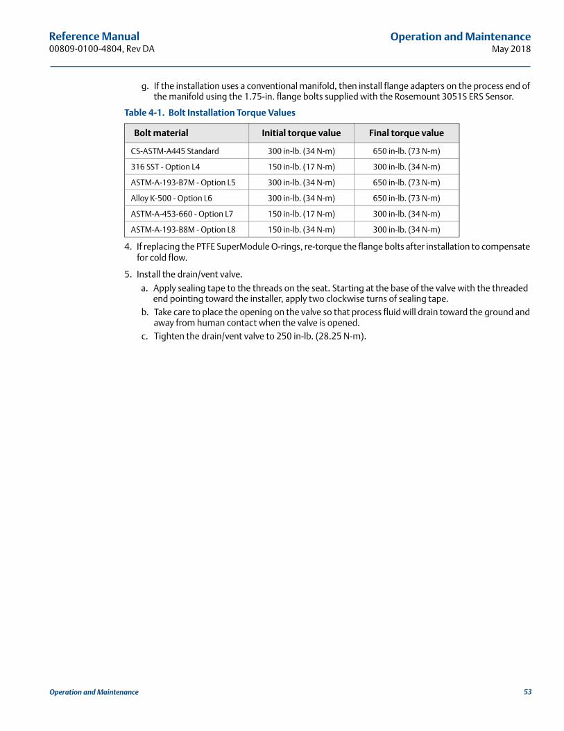
Reference Manual 00809-0100-4804, Rev DA
Operation and MaintenanceMay 2018
g. If the installation uses a conventional manifold, then install flange adapters on the process end of the manifold using the 1.75-in. flange bolts supplied with the Rosemount 3051S ERS Sensor.
Table 4-1. Bolt Installation Torque Values
4. If replacing the PTFE SuperModule O-rings, re-torque the flange bolts after installation to compensate for cold flow.
5. Install the drain/vent valve.
a. Apply sealing tape to the threads on the seat. Starting at the base of the valve with the threaded end pointing toward the installer, apply two clockwise turns of sealing tape.
b. Take care to place the opening on the valve so that process fluid will drain toward the ground and away from human contact when the valve is opened.
c. Tighten the drain/vent valve to 250 in-lb. (28.25 N-m).
Bolt material Initial torque value Final torque value
CS-ASTM-A445 Standard 300 in-lb. (34 N-m) 650 in-lb. (73 N-m)
316 SST - Option L4 150 in-lb. (17 N-m) 300 in-lb. (34 N-m)
ASTM-A-193-B7M - Option L5 300 in-lb. (34 N-m) 650 in-lb. (73 N-m)
Alloy K-500 - Option L6 300 in-lb. (34 N-m) 650 in-lb. (73 N-m)
ASTM-A-453-660 - Option L7 150 in-lb. (17 N-m) 300 in-lb. (34 N-m)
ASTM-A-193-B8M - Option L8 150 in-lb. (34 N-m) 300 in-lb. (34 N-m)
53Operation and Maintenance

54
Reference Manual00809-0100-4804, Rev DA
Operation and MaintenanceMay 2018
Operation and Maintenance

Reference Manual 00809-0100-4804, Rev DA
TroubleshootingMay 2018
55Troubleshooting
Section 5 Troubleshooting
Overview . . . . . . . . . . . . . . . . . . . . . . . . . . . . . . . . . . . . . . . . . . . . . . . . . . . . . . . . . . . . . . . . . . . . . . . . . . . . page 55Device overview . . . . . . . . . . . . . . . . . . . . . . . . . . . . . . . . . . . . . . . . . . . . . . . . . . . . . . . . . . . . . . . . . . . . . . page 55Measurement quality status . . . . . . . . . . . . . . . . . . . . . . . . . . . . . . . . . . . . . . . . . . . . . . . . . . . . . . . . . . . . page 59
5.1 OverviewThis section contains information for troubleshooting the Rosemount™ 3051S Electronic Remote Sensor (ERS)™ System. Diagnostic messages are communicated via the LCD display or a HART® host.
5.2 Device overviewProcedures and instructions in this section may require special precautions to ensure the safety of the personnel performing the operation. Information that raises potential safety issues is indicated with a warning symbol ( ). Refer to the following safety messages before performing an operation preceded by this symbol.
5.2.1 HART host diagnosticsThe ERS System provides numerous diagnostic alerts via a HART host, including a Field Communicator and AMS™ Device Manager.
Table 5-1 lists the possible diagnostic alerts that may be shown with the ERS System. The table provides a brief description of each alert and the recommended actions.
Table 5-2 provides summarized maintenance and troubleshooting suggestions for the most common operating problems. If a malfunction is suspected despite the absence of any diagnostic messages on a Field Communicator or host, follow the procedures described here to verify that ERS System and process connections are in good working order.
5.2.2 LCD display diagnosticsThe optional LCD display on the ERS System can show abbreviated operation, error, and warning messages for troubleshooting. Messages appear according to their priority; normal operating messages appear last. To determine the cause of a message, use a HART host to further interrogate the ERS System. A description of each LCD diagnostic message follows.
Error messagesAn error indicator message appears on the LCD display to warn of serious problems affecting the operation of the ERS System. The error message is displayed until the error condition is corrected; ERROR appears at the bottom of the display.
Warning messagesWarning messages appear on the LCD display to alert the user of user-repairable problems with the ERS System, or current operations. Warning messages appear alternately with other information until the warning condition is corrected or the ERS System completes the operation that triggered the warning message.

Reference Manual00809-0100-4804, Rev DA
TroubleshootingMay 2018
Table 5-1. Diagnostic Message Troubleshooting
LCD display message
Host diagnostic message
Possible problems Recommended actions
CURR SAT
mA Output Saturated
The primary variable has exceeded the range points defined for the 4–20 mA analog output signal. The analog output is fixed at the high or low saturation point and is not representative of the current process conditions.
Verify the process conditions and modify the Analog Range Values if necessary.
DPALERT System DP Alert
The ERS System is measuring a differential pressure value that exceeds the configured upper or lower alert value.
Verify the measured DP is beyond the trip limits. If necessary, modify the trip limits or disable the diagnostic.
FAIL BOARD ERROR
Electronics Error The electronics feature board in the ERS Primary Unit has malfunctioned. Replace the electronics feature board.
FAIL PHIERROR
PHI Module Failure The PHI sensor module has failed. Verify the PHI Module Temperature is within the operating limits of the sensor. Replace the PHI sensor module if necessary.
FAIL PLO ERROR
PLO Module Failure The PLO sensor module has failed. Verify the PLO Module Temperature is within the operating limits of the sensor. Replace the PLO sensor module if necessary.
FAILTHIERROR
PHI Module Failure The PHI sensor module has failed. Verify the PHI Module Temperature is within the operating limits of the sensor. Replace the PHI sensor module if necessary.
FAILTLOERROR
PLO Module Failure The PLO sensor module has failed. Verify the PLO Module Temperature is within the operating limits of the sensor. Replace the PLO sensor module if necessary.
PHIALERT PHI Pressure Alert
The PHI sensor module has detected a pressure value that exceeds the configured upper or lower alert value.
Verify the measured PHI Pressure is beyond the trip limits. If necessary, modify the trip limits or disable the diagnostic.
PHICOMMERROR
PHI Module Communication Error
Communication between the P-Hi sensor module and the electronics feature board has been lost.
Verify the wiring between the PHI module and the electronics feature board and cycle power to the entire ERS System. Replace the PHI module and/or electronics feature board if necessary.
PHILIMIT
PHI Pressure Out of Limits
The PHI Pressure reading has exceeded the sensor’s maximum measurement range.
Check the process for potential overpressure conditions.
PLOALERT PLO Pressure Alert
The PLO sensor module has detected a pressure value that exceeds the configured upper or lower alert value.
Verify the measured PLO Pressure is beyond the trip limits. If necessary, modify the trip limits or disable the diagnostic.
PLOCOMMERROR
PLO Module Communication Error
Communication between the PLO sensor module and the electronics feature board has been lost.
Verify the wiring between the PLO module and the electronics feature board and cycle power to the entire ERS System. Replace the PLO module and/or electronics feature board if necessary.
PLO LIMIT
PLO Pressure Out of Limits
The PLO Pressure reading has exceeded the sensor’s maximum measurement range.
Check the process for potential overpressure conditions.
LOOPTEST mA Output Fixed
The analog output of the ERS System is in “fixed current mode” and is not representative of the HART PV.
Using a Field Communicator or AMS Device Manager, disable “Loop Current Mode.”
SNSRCOMMERROR
Sensor Module Missing
A sensor module is missing or not detected.
Verify that both sensors are connected and properly wired.
SNSRCONFIGERROR
No PHI Module Configuration Present
Neither of the modules in the ERS System are configured as the PHI sensor.
Verify that both sensors are connected and properly wired. Change the pressure designation of one of the two modules to “PHI” using a Field Communicator or AMS Device Manager.
56 Troubleshooting

Reference Manual 00809-0100-4804, Rev DA
TroubleshootingMay 2018
SNSRCONFIGERROR
No PLO Module Configuration Present
Neither of the modules in the ERS System are configured as the PLO sensor.
Verify that both sensors are connected and properly wired. Change the pressure designation of one of the two modules to “PLO” using a Field Communicator or AMS Device Manager.
SNSRCONFIGERROR
Unknown Sensor Module Configuration
The configuration of one or both sensor modules is unknown.
Verify that both sensors are connected and properly wired. Using a Field Communicator or AMS Device Manager, assign one of the modules as the “PHI” sensor and the other module as the “PLO” sensor.
SNSRINCOMPERROR
Sensor Module Incompatibility
The ERS System contains two sensor modules that will not work together.
The ERS System cannot contain one gage and one absolute sensor. Replace one of the two modules so that both sensors are either gage or absolute.
STUCKKEY Stuck “Span” Button The “Span” button on the electronics
feature board is stuck.
Locate the ERS Primary Unit, remove the front housing cover (considering hazardous location requirements), and gently pry the span button.
STUCKKEY Stuck “Zero” Button The “Zero” button on the electronics
feature board is stuck.
Locate the ERS Primary Unit, remove the front housing cover (considering hazardous location requirements), and gently pry the zero button.
THIALERT
PHI Temperature Alert
The PHI sensor module has detected a temperature value that exceeds the configured upper or lower alert value.
Verify the measured PHI temperature is beyond the trip limits. If necessary, modify the trip limits or disable the diagnostic.
THILIMIT
PHI Module Temp. Out of Limits
The internal temperature sensor on the PHI Pressure module has exceeded the safe operating range.
Verify the ambient conditions do not exceed the temperature limits of the pressure module (–40 to 185 °F/–40 to 85 °C).
TLOALERT
PLO Temperature Alert
The PLO sensor module has detected a temperature value that exceeds the configured upper or lower alert value.
Verify the measured PLO temperature is beyond the trip limits. If necessary, modify the trip limits or disable the diagnostic.
TLO LIMIT
PLO Module Temp. Out of Limits
The internal temperature sensor on the PLO Pressure module has exceeded the safe operating range.
Verify the ambient conditions do not exceed the temperature limits of the pressure module (–40 to 185 °F/–40 to 85 °C).
XMTR INFO
Non-Volatile Memory Warning
ERS System information data is incomplete. ERS System operation will not be affected.
Replace the electronics feature board at the next maintenance shutdown.
XMTR INFO ERROR
Non-Volatile Memory Error Non-volatile data of the device is corrupt. Replace the electronics feature board.
(LCD is blank) LCD Update Error
The electronics circuit board on the ERS Primary Unit has lost communication with the LCD display.
Examine the LCD Connector and reinstall and re-power the LCD display. If the problem persists, first replace the LCD display then replace the feature board electronics if necessary.
NO UPDATE LCD Update Error The LCD display on the ERS Primary Unit is not updating
Make sure the correct LCD display has been installed (refer to Ordering Information, Specifications, and Drawings for LCD display part number).
Table 5-1. Diagnostic Message Troubleshooting
LCD display message
Host diagnostic message
Possible problems Recommended actions
57Troubleshooting

Reference Manual00809-0100-4804, Rev DA
TroubleshootingMay 2018
58 Troubleshooting
Table 5-2. Rosemount ERS System Troubleshooting
Symptom Corrective actions
The mA output of the Rosemount ERS System is zero
• Verify power is applied to “+” and “-” PWR/COMM terminals on the ERS primary unit
• Check power wires for reversed polarity
• Verify terminal voltage is 16 to 42.4 Vdc
• Check for open diode across test terminals on the ERS primary unit.
The Rosemount ERS System is not communicating with a Field Communicator or AMS Device Manager
• Verify the output is between 4 and 20 mA or saturation levels
• Verify clean DC Power to transmitter (Max AC noise 0.2 volts peak to peak)
• Check loop resistance, 250–1321 ΩLoop Resistance = (Power supply voltage – transmitter voltage)/loop current
• Check if ERS System is at an alternate HART address
The mA output of Rosemount ERS System is low or high
• Verify applied process conditions
• Verify the desired process variable is mapped to the HART PV
• Verify 4 and 20 mA range points
• Verify output is not in alarm or saturation condition
• An analog output trim or sensor trim may be required
The Rosemount ERS System is not responding to changes in measured process variables
• Check to ensure isolation valves are not closed
• Check test equipment
• Check impulse piping or manifold for blockage
• Verify primary variable measurement is between the 4 and 20 mA set points
• Verify output is not in alarm or saturation condition
• Verify ERS System is not in Loop Test, Multidrop, Test Calculation, or Fixed Variable mode
Digital Variable output is too low or high
• Check test equipment (verify accuracy)
• Check impulse piping for blockage or low fill in wet leg
• Verify sensor trim on each pressure sensor
• Verify measured variables are within all sensor limits
Digital Variable output is erratic
• Verify power source to ERS System has adequate voltage and current
• Check for external electrical interference
• Verify ERS System is properly grounded
• Verify shield for twisted pairs only grounded at both ends
The Rosemount ERS System output is normal, but the LCD display is off and diagnostics indicate an LCD display problem
• Verify LCD display is installed correctly
• Replace LCD display
The DP calculation is negative • The AO is saturated low, verify that DP variable is a possible value – if negative, PHI and PLO may be reversed.
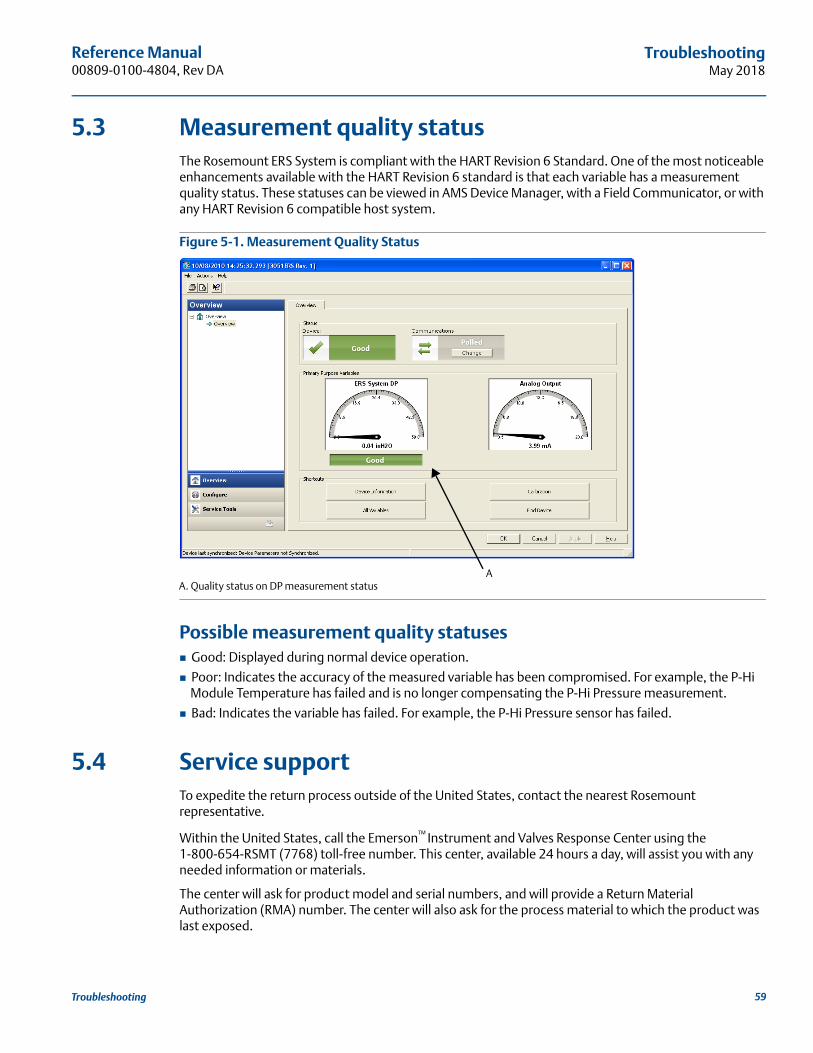
Reference Manual 00809-0100-4804, Rev DA
TroubleshootingMay 2018
5.3 Measurement quality statusThe Rosemount ERS System is compliant with the HART Revision 6 Standard. One of the most noticeable enhancements available with the HART Revision 6 standard is that each variable has a measurement quality status. These statuses can be viewed in AMS Device Manager, with a Field Communicator, or with any HART Revision 6 compatible host system.
Figure 5-1. Measurement Quality Status
A. Quality status on DP measurement status
Possible measurement quality statuses Good: Displayed during normal device operation.
Poor: Indicates the accuracy of the measured variable has been compromised. For example, the P-Hi Module Temperature has failed and is no longer compensating the P-Hi Pressure measurement.
Bad: Indicates the variable has failed. For example, the P-Hi Pressure sensor has failed.
5.4 Service supportTo expedite the return process outside of the United States, contact the nearest Rosemount representative.
Within the United States, call the Emerson™ Instrument and Valves Response Center using the 1-800-654-RSMT (7768) toll-free number. This center, available 24 hours a day, will assist you with any needed information or materials.
The center will ask for product model and serial numbers, and will provide a Return Material Authorization (RMA) number. The center will also ask for the process material to which the product was last exposed.
A
59Troubleshooting

Reference Manual00809-0100-4804, Rev DA
TroubleshootingMay 2018
Emerson Instrument and Valves Response Center representatives will explain the additional information and procedures necessary to return goods exposed to hazardous substances.
Individuals who handle products exposed to a hazardous substance can avoid injury if they are informed of and understand the hazard. If the product being returned was exposed to a hazardous substance as defined by OSHA, a copy of the required Material Safety Data Sheet (MSDS) for each hazardous substance identified must be included with the returned goods.
60 Troubleshooting

Reference Manual 00809-0100-4804, Rev DA
Safety Instrumented SystemsMay 2018
Section 6 Safety Instrumented Systems Requirements
Safety Instrumented Systems (SIS) Certification . . . . . . . . . . . . . . . . . . . . . . . . . . . . . . . . . . . . . . . . . . page 61
6.1 Safety Instrumented Systems (SIS) CertificationThe Rosemount™ 3051S Electronic Remote Sensor (ERS)™ System is a two wire, 4–20 mA architecture that calculates differential pressure electronically using two pressure sensors that are linked together with a digital cable. The transmitter system uses standard, well-proven sensor boards in combination with a microprocessor board that performs diagnostics. It is programmed to send its output to a specified failure state, either high or low, when an internal failure is detected. It is assumed that the 4–20 mA output is used as a primary safety variable. No other output variants are covered by this report; Type B.
SIL 2 for random integrity at HFT = 0
SIL 3 for random integrity at HFT = 1
SIL 3 for systematic integrity
6.1.1 Rosemount ERS Systems safety certified identificationAll Rosemount 3051S Transmitters must be identified as safety certified before installing into SIS systems.
To identify a safety certified Rosemount ERS System, verify the following information:
Model string should contain 3051SAM, 3051SAL_P, or 3051SAL_S
Software revision should be 57 or higher
Model string should contain option code QT
Maximum ERS cable length for SIS certification is 200 ft. (60.96 m). Cable must also meet the specifications from “Rosemount 3051S ERS System cable specifications” on page 16.
6.1.2 Installation in SIS applicationsInstallations are to be performed by qualified personnel. No special installation is required in addition to the standard installation practices outlined in “Connect wiring and power up” on page 15. Always ensure a proper seal by installing the electronics housing cover(s) so that metal contacts metal.
Environmental and operational limits are available in Appendix A: Reference Data.
The loop should be designed so the terminal voltage does not drop below 16 Vdc when the transmitter output is set to 23 mA. Refer to Appendix A: Reference Data to verify limitation.
Position the security switch to the ( ) position to prevent accidental or deliberate change of configuration data during normal operation.
61Safety Instrumented Systems

Reference Manual00809-0100-4804, Rev DA
Safety Instrumented SystemsMay 2018
6.1.3 Configuring in SIS applicationsUse any HART®-capable configuration tool to communicate with and verify configuration of the Rosemount ERS System.
NoteTransmitter output is not safety-rated during the following; configuration changes, multidrop, and loop test. Alternative means should be used to ensure process safety during transmitter configuration and maintenance activities.
Damping User-selected damping will affect the transmitters ability to respond to changes in the applied process. The damping value + response time must not exceed the loop requirements.
Reference “Damping” on page 27 to change damping value.
Alarm and saturation levelsDistributed Control System (DCS) or safety logic solver should be configured to match transmitter configuration. Figure 6-1 identifies the three alarm levels available and their operation values.
Figure 6-1. Alarm Levels
Rosemount alarm level
Namur alarm level
Custom alarm level
1. Transmitter Failure, hardware or software alarm in LO position. 2. Transmitter Failure, hardware or software alarm in HI position.
Normal operation
4 mA 20 mA20.8 mA
high saturation
21.75(2)
3.9 mAlow saturation
3.75 mA(1)
Normal operation
4 mA 20 mA20.5 mA
high saturation
22.5(2)
3.8 mAlow saturation
3.6 mA(1)
4 mA 20 mA20.1 - 22.9 mAhigh saturation
20.2 - 23.0(2)
3.7 - 3.9 mAlow saturation
3.6 - 3.8 mA(1)
Normal operation
62 Safety Instrumented Systems
Reference Manual 00809-0100-4804, Rev DA
Safety Instrumented SystemsMay 2018
6.1.4 Rosemount 3051S SIS operation and maintenance
Proof testThe following proof tests are recommended.
In the even an error is found in the safety and functionality, proof test results and corrective actions taken can be documented at Emerson.com/Rosemount/Safety-Web-Apps/Report.
All proof test procedures must be carried out by qualified personnel.
Use Fast Keys referenced in “Calibration” on page 44 to perform a Loop Test, Analog Output Trim, or Sensor Trim. Security switch should be in the ( ) position during proof test execution and repositioned in the ( ) position after execution.
Comprehensive proof testThe comprehensive proof test consists of performing the same steps as the simple suggested proof test and a two point calibration of the pressure sensor. Reference the FMEDA Report for percent of possible DU failures in the device.
FMEDA report can be found at Emerson.com/Rosemount/Safety.
Required tools: Field Communicator and pressure calibration equipment.
1. Bypass the safety function and take appropriate action to avoid a false trip.
2. Use HART communications to retrieve any diagnostics and take appropriate action.
3. Send a HART command to the transmitter to go to the high alarm current output and verify that the analog current reaches that value(1).
4. Send a HART command to the transmitter to go to the low alarm current output and verify that the analog current reaches that value(2).
5. Perform complete system calibration (zero and upper trims for PHI and PLO, zero trim for DP)
6. Remove the bypass and otherwise restore normal operation.
7. Place the Security switch in the ( ) position.
Note The user determines the proof test requirements for impulse piping.
Automatic diagnostics are defined for the corrected % DU: The tests performed internally by the device during runtime without requiring enabling or programming by the user.
6.1.5 Inspection
Visual inspectionNot required
Special toolsNot required
1. This tests for compliance voltage problems such as a low power supply voltage or increased wiring resistance. This also tests for other possible failures.2. This tests for possible quiescent current related failures.
63Safety Instrumented Systems

Reference Manual00809-0100-4804, Rev DA
Safety Instrumented SystemsMay 2018
Product repairThe Rosemount 3051S ERS is repairable by major component replacement.
All failures detected by the transmitter diagnostics or by the proof-test must be reported. Feedback can be submitted electronically at Emerson.com/Rosemount/Safety-Web-Apps/Report.
All product repair and part replacement should be performed by qualified personnel.
Rosemount 3051S ERS SIS referenceThe Rosemount 3051S ERS must be operated in accordance to the functional and performance specifications provided in Appendix A: Reference Data.
Failure rate dataThe FMEDA report includes failure rates. The report is available at Emerson.com/Rosemount/Safety.
Failure values Safety deviation (% of analog span shift that defines a dangerous failure): two percent
System response time: see “Ordering Information, Specifications, and Drawings” on page 65
Self-diagnostics test interval: at least once every 60 minutes
Product life50 years - based on worst case component wear-out mechanisms (not based on wear-out of process wetted materials)
Report any safety related product information at Emerson.com/Rosemount/Safety-Products/Equipment-lists.
64 Safety Instrumented Systems

Reference Manual 00809-0100-4804, Rev DA
Reference DataMay 2018
Appendix A Reference Data
Product Certifications . . . . . . . . . . . . . . . . . . . . . . . . . . . . . . . . . . . . . . . . . . . . . . . . . . . . . . . . . . . . . . . . . page 65Ordering Information, Specifications, and Drawings . . . . . . . . . . . . . . . . . . . . . . . . . . . . . . . . . . . . . . . page 65
A.1 Product CertificationsTo view current Rosemount™ 3051S ERS™ Product Certifications, follow these steps:
1. Go to Emerson.com/Rosemount/Rosemount-3051S-ERS.
2. Scroll as needed to the green menu bar and click Documents & Drawings.
3. Click Manuals & Guides.
4. Select the appropriate Quick Start Guide.
A.2 Ordering Information, Specifications, and Drawings
To view current Rosemount 3051S ERS Ordering Information, Specifications, and Drawings, follow these steps:
1. Go to Emerson.com/Rosemount/Rosemount-3051S-ERS.
2. Scroll as needed to the green menu bar and click Documents & Drawings.
3. For installation drawings, click Drawings & Schematics and select the appropriate document.
4. For ordering information, specifications, and dimensional drawings, click Data Sheets & Bulletins and select the appropriate Product Data Sheet.
Reference Data 65
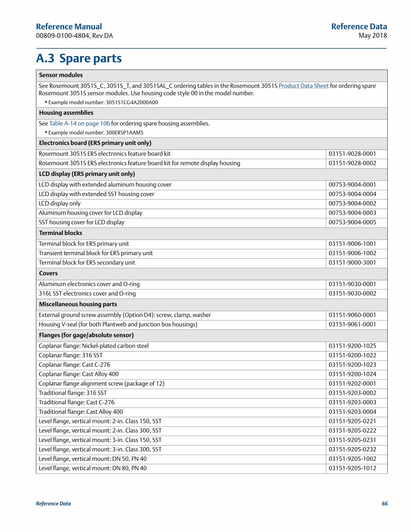
Reference DataMay 2018
Reference Manual 00809-0100-4804, Rev DA
A.3 Spare partsSensor modules
See Rosemount 3051S_C, 3051S_T, and 3051SAL_C ordering tables in the Rosemount 3051S Product Data Sheet for ordering spare Rosemount 3051S sensor modules. Use housing code style 00 in the model number.
•Example model number: 3051S1CG4A2000A00
Housing assemblies
See Table A-14 on page 106 for ordering spare housing assemblies.
•Example model number: 300ERSP1AAM5
Electronics board (ERS primary unit only)
Rosemount 3051S ERS electronics feature board kit 03151-9028-0001
Rosemount 3051S ERS electronics feature board kit for remote display housing 03151-9028-0002
LCD display (ERS primary unit only)
LCD display with extended aluminum housing cover 00753-9004-0001
LCD display with extended SST housing cover 00753-9004-0004
LCD display only 00753-9004-0002
Aluminum housing cover for LCD display 00753-9004-0003
SST housing cover for LCD display 00753-9004-0005
Terminal blocks
Terminal block for ERS primary unit 03151-9006-1001
Transient terminal block for ERS primary unit 03151-9006-1002
Terminal block for ERS secondary unit 03151-9000-3001
Covers
Aluminum electronics cover and O-ring 03151-9030-0001
316L SST electronics cover and O-ring 03151-9030-0002
Miscellaneous housing parts
External ground screw assembly (Option D4): screw, clamp, washer 03151-9060-0001
Housing V-seal (for both Plantweb and Junction box housings) 03151-9061-0001
Flanges (for gage/absolute sensor)
Coplanar flange: Nickel-plated carbon steel 03151-9200-1025
Coplanar flange: 316 SST 03151-9200-1022
Coplanar flange: Cast C-276 03151-9200-1023
Coplanar flange: Cast Alloy 400 03151-9200-1024
Coplanar flange alignment screw (package of 12) 03151-9202-0001
Traditional flange: 316 SST 03151-9203-0002
Traditional flange: Cast C-276 03151-9203-0003
Traditional flange: Cast Alloy 400 03151-9203-0004
Level flange, vertical mount: 2-in. Class 150, SST 03151-9205-0221
Level flange, vertical mount: 2-in. Class 300, SST 03151-9205-0222
Level flange, vertical mount: 3-in. Class 150, SST 03151-9205-0231
Level flange, vertical mount: 3-in. Class 300, SST 03151-9205-0232
Level flange, vertical mount: DN 50, PN 40 03151-9205-1002
Level flange, vertical mount: DN 80, PN 40 03151-9205-1012
Reference Data 66

Reference DataMay 2018
Reference Manual00809-0100-4804, Rev DA
Flange adapter kits (each kit contains adapter, bolts, and O-rings [qty 2])
CS bolts, glass filled PTFE O-rings
SST adapters 03031-1300-0002
Cast C-276 adapters 03031-1300-0003
Cast Alloy 400 adapters 03031-1300-0004
Ni plated CS adapters 03031-1300-0005
SST bolts, glass filled PTFE O-rings
SST adapters 03031-1300-0012
Cast C-276 adapters 03031-1300-0013
Cast Alloy 400 adapters 03031-1300-0014
Ni plated CS adapters 03031-1300-0015
Flange adapter kits (each kit contains adapter, bolts, and O-rings [qty 2])
CS bolts, graphite PTFE O-rings
SST adapters 03031-1300-0102
Cast C-276 adapters 03031-1300-0103
Cast Alloy 400 adapters 03031-1300-0104
Ni Plated CS adapters 03031-1300-0105
SST bolts, graphite PTFE O-rings
SST adapters 03031-1300-0112
Cast C-276 adapters 03031-1300-0113
Cast Alloy 400 adapters 03031-1300-0114
Ni plated CS adapters 03031-1300-0115
Flange adapter
Nickel-plated carbon steel 03151-9259-0005
316 SST 03151-9259-0002
Cast C-276 03151-9259-0003
Cast Alloy 400 03151-9259-0004
Drain/vent kits
316 SST valve stem and seat kit 03151-9268-0012
Alloy C-276 valve stem and seat kit 03151-9268-0013
Alloy K-500 valve stem and Alloy 400 seat kit 03151-9268-0014
316 SST ceramic ball drain/vent kit 03151-9268-0112
Alloy C-276 ceramic ball drain/vent kit 03151-9268-0113
Alloy 400/K-500 ceramic ball drain/vent kit 03151-9268-0114
O-rings (qty 12)
Electronics housing, cover 03151-9040-0001
Electronics housing, module 03151-9041-0001
Process flange, glass-filled PTFE 03151-9042-0001
Process flange, graphite-filled PTFE 03151-9042-0002
Flange adapter, glass-filled PTFE 03151-9043-0001
Flange adapter, graphite-filled PTFE 03151-9043-0002
Gland and collar kits
Gland and collar kits 03151-9250-0001
Armor cable gland, 711/A/050/NPT CBL GLAND IECEx 03151-9103-0001
Armor cable gland, 711/A/050/M20 CBL GLAND IECEx 03151-9103-0002
Reference Data67
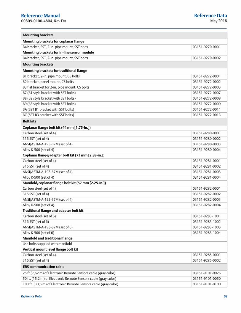
Reference DataMay 2018
Reference Manual 00809-0100-4804, Rev DA
Mounting brackets
Mounting brackets for coplanar flange
B4 bracket, SST, 2-in. pipe mount, SST bolts 03151-9270-0001
Mounting brackets for in-line sensor module
B4 bracket, SST, 2-in. pipe mount, SST bolts 03151-9270-0002
Mounting brackets
Mounting brackets for traditional flange
B1 bracket, 2-in. pipe mount, CS bolts 03151-9272-0001
B2 bracket, panel mount, CS bolts 03151-9272-0002
B3 flat bracket for 2-in. pipe mount, CS bolts 03151-9272-0003
B7 (B1 style bracket with SST bolts) 03151-9272-0007
B8 (B2 style bracket with SST bolts) 03151-9272-0008
B9 (B3 style bracket with SST bolts) 03151-9272-0009
BA (SST B1 bracket with SST bolts) 03151-9272-0011
BC (SST B3 bracket with SST bolts) 03151-9272-0013
Bolt kits
Coplanar flange bolt kit (44 mm [1.75-in.])
Carbon steel (set of 4) 03151-9280-0001
316 SST (set of 4) 03151-9280-0002
ANSI/ASTM-A-193-B7M (set of 4) 03151-9280-0003
Alloy K-500 (set of 4) 03151-9280-0004
Coplanar flange/adapter bolt kit (73 mm [2.88-in.])
Carbon steel (set of 4) 03151-9281-0001
316 SST (set of 4) 03151-9281-0002
ANSI/ASTM-A-193-B7M (set of 4) 03151-9281-0003
Alloy K-500 (set of 4) 03151-9281-0004
Manifold/coplanar flange bolt kit (57 mm [2.25-in.])
Carbon steel (set of 4) 03151-9282-0001
316 SST (set of 4) 03151-9282-0002
ANSI/ASTM-A-193-B7M (set of 4) 03151-9282-0003
Alloy K-500 (set of 4) 03151-9282-0004
Traditional flange and adapter bolt kit
Carbon steel (set of 6) 03151-9283-1001
316 SST (set of 6) 03151-9283-1002
ANSI/ASTM-A-193-B7M (set of 6) 03151-9283-1003
Alloy K-500 (set of 6) 03151-9283-1004
Manifold and traditional flange
Use bolts supplied with manifold
Vertical mount level flange bolt kit
Carbon steel (set of 4) 03151-9285-0001
316 SST (set of 4) 03151-9285-0002
ERS communication cable
25 ft (7,62 m) of Electronic Remote Sensors cable (gray color) 03151-9101-0025
50 ft. (15,2 m) of Electronic Remote Sensors cable (gray color) 03151-9101-0050
100 ft. (30,5 m) of Electronic Remote Sensors cable (gray color) 03151-9101-0100
Reference Data 68
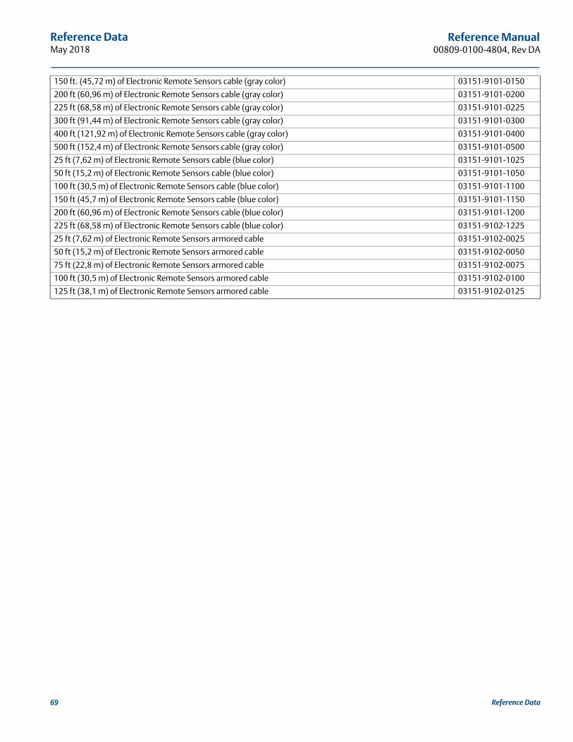
Reference DataMay 2018
Reference Manual00809-0100-4804, Rev DA
150 ft. (45,72 m) of Electronic Remote Sensors cable (gray color) 03151-9101-0150
200 ft (60,96 m) of Electronic Remote Sensors cable (gray color) 03151-9101-0200
225 ft (68,58 m) of Electronic Remote Sensors cable (gray color) 03151-9101-0225
300 ft (91,44 m) of Electronic Remote Sensors cable (gray color) 03151-9101-0300
400 ft (121,92 m) of Electronic Remote Sensors cable (gray color) 03151-9101-0400
500 ft (152,4 m) of Electronic Remote Sensors cable (gray color) 03151-9101-0500
25 ft (7,62 m) of Electronic Remote Sensors cable (blue color) 03151-9101-1025
50 ft (15,2 m) of Electronic Remote Sensors cable (blue color) 03151-9101-1050
100 ft (30,5 m) of Electronic Remote Sensors cable (blue color) 03151-9101-1100
150 ft (45,7 m) of Electronic Remote Sensors cable (blue color) 03151-9101-1150
200 ft (60,96 m) of Electronic Remote Sensors cable (blue color) 03151-9101-1200
225 ft (68,58 m) of Electronic Remote Sensors cable (blue color) 03151-9102-1225
25 ft (7,62 m) of Electronic Remote Sensors armored cable 03151-9102-0025
50 ft (15,2 m) of Electronic Remote Sensors armored cable 03151-9102-0050
75 ft (22,8 m) of Electronic Remote Sensors armored cable 03151-9102-0075
100 ft (30,5 m) of Electronic Remote Sensors armored cable 03151-9102-0100
125 ft (38,1 m) of Electronic Remote Sensors armored cable 03151-9102-0125
Reference Data69

Reference DataMay 2018
Reference Manual 00809-0100-4804, Rev DA
Reference Data 70


Reference Manual00809-0100-4804, Rev DA
May 2018
Global HeadquartersEmerson Automation Solutions 6021 Innovation Blvd.Shakopee, MN 55379, USA
+1 800 999 9307 or +1 952 906 8888+1 952 949 7001 [email protected]
North America Regional OfficeEmerson Automation Solutions8200 Market Blvd.Chanhassen, MN 55317, USA
+1 800 999 9307 or +1 952 906 8888+1 952 949 7001 [email protected]
Latin America Regional OfficeEmerson Automation Solutions1300 Concord Terrace, Suite 400Sunrise, FL 33323, USA
+1 954 846 5030+1 954 846 [email protected]
Europe Regional OfficeEmerson Automation Solutions Europe GmbHNeuhofstrasse 19a P.O. Box 1046CH 6340 BaarSwitzerland
+41 (0) 41 768 6111+41 (0) 41 768 6300 [email protected]
Asia Pacific Regional OfficeEmerson Automation Solutions 1 Pandan CrescentSingapore 128461
+65 6777 8211+65 6777 0947 [email protected]
Middle East and Africa Regional OfficeEmerson Automation SolutionsEmerson FZE P.O. Box 17033Jebel Ali Free Zone - South 2Dubai, United Arab Emirates
+971 4 8118100+971 4 8865465 [email protected]
Linkedin.com/company/Emerson-Automation-Solutions
Twitter.com/Rosemount_News
Facebook.com/Rosemount
Youtube.com/user/RosemountMeasurement
Google.com/+RosemountMeasurement
Standard Terms and Conditions of Sale can be found on the Terms and Conditions of Sale page.The Emerson logo is a trademark and service mark of Emerson Electric Co. Rosemount is a mark of one of the Emerson family of companies. All other marks are the property of their respective owners.© 2018 Emerson. All rights reserved.