MANUAL RE-PAINT AXIS P551X/-E Network Dome … · AXIS 66583 REV: 2 COMMUNICATIONS AB MANUAL...
23
MANUAL RE-PAINT AXIS P551X/-E Network Dome Cameras
Transcript of MANUAL RE-PAINT AXIS P551X/-E Network Dome … · AXIS 66583 REV: 2 COMMUNICATIONS AB MANUAL...

MANUAL RE-PAINT AXIS P551X/-E
Network Dome Cameras

AXIS 66583 REV: 2 COMMUNICATIONS AB MANUAL RE-PAINT INST AXIS P551X/-E DATE: 2016-04-07
Author: Sven Svensson PAGE: 2(23)
- 2 -
1 Table of Contents
1 Table of Contents ________________________________________________________ 2
2 Introduction ____________________________________________________________ 3
3 Influence on Warranty and Product performance ______________________________ 3
3.1 Product Warranty _________________________________________________________ 3
3.2 Product Performance ______________________________________________________ 3
4 Tools Required __________________________________________________________ 3
5 Repaint instruction for P551X-E series ______________________________________ 4
5.1 Repainting of the Chassis ___________________________________________________ 4 5.1.1 Removal of weather shield _______________________________________________________ 4 5.1.2 Removal of the Dome Module Ass _________________________________________________ 5 5.1.3 Removal of the Push-pull Connector Housing ________________________________________ 6 5.1.4 Removal of the Chassis Hook _____________________________________________________ 7 5.1.5 Removal of the Screws Bayonett __________________________________________________ 7 5.1.6 Create a masking box for the Chassis and position the unit ______________________________ 8 5.1.7 Masking of the Chassis __________________________________________________________ 9
5.2 Repainting of the Dome Module Ass _________________________________________ 10 5.2.1 Removal of the Dome Module Bracket & the Dome with sealing ________________________ 10 5.2.2 Removal of the dome sealing ____________________________________________________ 12 5.2.3 Mask Gore filters. _____________________________________________________________ 12
6 Repaint instruction for P551X series _______________________________________ 13
6.1 Repainting of the Chassis __________________________________________________ 13 6.1.1 Removal of the Chassis Hook and Lid _____________________________________________ 14 6.1.2 Removal of the Screws Bayonett _________________________________________________ 14 6.1.3 Create a masking box for the Chassis and position the unit _____________________________ 16 6.1.4 Masking of the Chassis _________________________________________________________ 16
6.2 Repainting of the Dome Module Ass _________________________________________ 18 6.2.1 Removal of the Dome Module Bracket & the Dome with sealing ________________________ 18 6.2.2 Removal of the dome sealing ____________________________________________________ 19
7 APPENDIX: Assembly drawings and overview of products _____________________ 20
7.1 Assembly drawings of P551X-E series _______________________________________ 20 7.1.1 Main Assembly _______________________________________________________________ 20 7.1.2 Weather Shield Assembly _______________________________________________________ 21 7.1.3 Dome Module Assembly ________________________________________________________ 21
7.2 Assembly drawings of P551X series _________________________________________ 22 7.2.1 Main Assembly _______________________________________________________________ 22 7.2.2 Dome Module Assembly ________________________________________________________ 22
8 Revision History ________________________________________________________ 23

AXIS 66583 REV: 2 COMMUNICATIONS AB MANUAL RE-PAINT INST AXIS P551X/-E DATE: 2016-04-07
Author: Sven Svensson PAGE: 3(23)
- 3 -
2 Introduction This document describes the way to operate when Re-painting a P551X / -E Network Dome Camera. Any attempt to carry out a Re-painting operation on the camera, should only be made after reading this document thoroughly. To prevent damage to sensitive components, proper ESD protection must be carried out while handling of the parts is only allowed in dust free environment.
3 Influence on Warranty and Product performance
3.1 Product Warranty Any aftermarket modifications, which are not approved by Axis Communications AB, made on Axis Network Dome cameras will void the Product warranty. Therefore, please note that any deviation from the re-paint instructions described in this document will void the Product warranty.
3.2 Product Performance Axis Communications AB will only guarantee the product specifications and performance of the camera in its original form.
4 Tools Required
Torx Screwdriver, (T8, T10, T20)
Screwdriver Flat > 6 mm width
Carton box min 190x190x140 mm
Knife for cutting in carton

AXIS 66583 REV: 2 COMMUNICATIONS AB MANUAL RE-PAINT INST AXIS P551X/-E DATE: 2016-04-07
Author: Sven Svensson PAGE: 4(23)
- 4 -
5 Repaint instruction for P551X-E series To repaint the P551X-E series Dome Network Camera, the camera will have to be divided into thee parts: Weather Shield, Chassis and Dome Module. Each part is then stripped from components or masked to enable the repainting. Before the painting, crucial parts of the camera are masked to ensure the fit and function when the camera is reassembled again. To prevent damage to sensitive components, proper ESD protection must be carried out while handling of the parts is only allowed in dust free environment. Please follow the workflow as described below. Any deviations from the proposed instruction will void the Product warranty.
5.1 Repainting of the Chassis Please note that the original surface finish of the chassis is Powder coating.
5.1.1 Removal of weather shield
Tool: Screwdriver Torx20 Torque (when refitting): 2 Nm Put the weather shield to the side for painting.
Screws (3x) T20

AXIS 66583 REV: 2 COMMUNICATIONS AB MANUAL RE-PAINT INST AXIS P551X/-E DATE: 2016-04-07
Author: Sven Svensson PAGE: 5(23)
- 5 -
5.1.2 Removal of the Dome Module Ass Step 1 Remove the four Antiloss screws that hold the Dome module ass. Remove the Dome module ass. Tool: Screwdriver Torx20 Torque (when refitting): 2 Nm
When refitting, Please note:
1) The Max tightening torque must not exceed 2 Nm
Antiloss Screws (4x)

AXIS 66583 REV: 2 COMMUNICATIONS AB MANUAL RE-PAINT INST AXIS P551X/-E DATE: 2016-04-07
Author: Sven Svensson PAGE: 6(23)
- 6 -
5.1.3 Removal of the Push-pull Connector Housing Step 1 Remove the two screws that hold the Push-pull connector housing and remove the housing. Tool: Screwdriver Torx8 Torque (when refitting): 0,3Nm
Screws (3x)
Push Pull Housing

AXIS 66583 REV: 2 COMMUNICATIONS AB MANUAL RE-PAINT INST AXIS P551X/-E DATE: 2016-04-07
Author: Sven Svensson PAGE: 7(23)
- 7 -
5.1.4 Removal of the Chassis Hook Step 1 Remove the three screws that hold the Chassis hook. Tool: Screwdriver Torx20 Torque (when refitting): 2,4Nm
When refitting, Please note: Please note the maximum torque of 2,4 Nm.
5.1.5 Removal of the Screws Bayonett Remove the three Bayonett screws. Tool: Screwdriver, Minus Bit Torque (when refitting): 1,8Nm
When refitting, Please note: Please note the maximum torque of 1,8Nm.
Screws (3x)
Chassis hook
Screw Bayonett (3x)
AXIS 66583 REV: 2 COMMUNICATIONS AB MANUAL RE-PAINT INST AXIS P551X/-E DATE: 2016-04-07
Author: Sven Svensson PAGE: 8(23)
- 8 -
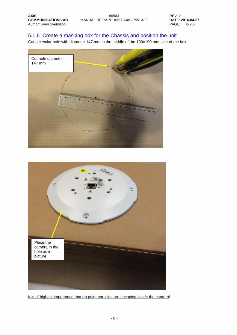
5.1.6 Create a masking box for the Chassis and position the unit Cut a circular hole with diameter 147 mm in the middle of the 190x190 mm side of the box.
It is of highest importance that no paint particles are escaping inside the camera!
Place the camera in the hole as in picture
Cut hole diameter 147 mm

AXIS 66583 REV: 2 COMMUNICATIONS AB MANUAL RE-PAINT INST AXIS P551X/-E DATE: 2016-04-07
Author: Sven Svensson PAGE: 9(23)
- 9 -
5.1.7 Masking of the Chassis In order to maintain the fit and function of the camera, some parts of it need to be masked before painting. This applies to parts like threaded screw holes, assembly surfaces as well as electrical connectors. Step 1 Mask all the 19 threaded screwholes and the connector together with the corresponding slot on the top surface of the chassis.
One easy way, to mask all above mentioned features, is to attach a mask with a diameter of 90mm in one piece all over them, as shown in the picture below.
Connector with slot in chassis
One of 16 threaded screwholes

AXIS 66583 REV: 2 COMMUNICATIONS AB MANUAL RE-PAINT INST AXIS P551X/-E DATE: 2016-04-07
Author: Sven Svensson PAGE: 10(23)
- 10 -
5.2 Repainting of the Dome Module Ass When repainting the Dome Module ass, the Cover is the part to repaint. Please follow each step described below. As mentioned earlier, the proper masking before painting is of highest importance in order to ensure good fit and function when reassembling the camera again. Please note that any deviation from the steps described below will void the product warranty. Please note that the original surface finish of the Dome cover ring is PC+ASA. Please use compatible paint.
5.2.1 Removal of the Dome Module Bracket & the Dome with sealing Remove the eight screws that hold the Dome module bracket. Remove the Dome Module bracket together with the Dome with sealing. Tool: Screwdriver Torx T10 Torque (when refitting): 0,25 Nm
Mask, 90mm in diameter

AXIS 66583 REV: 2 COMMUNICATIONS AB MANUAL RE-PAINT INST AXIS P551X/-E DATE: 2016-04-07
Author: Sven Svensson PAGE: 11(23)
- 11 -
When refitting, Please note: 1) Please note the maximum torque of 0,25Nm. 2) The screws are self threading in the plastic. It is important that the screws thread enter the plastic in the same position as in the original mounting. Turn the screws anti-clockvise to get the feeling where the original thread start.
Dome Module bracket)
Screws (8x)
Dome with Sealing
Built-in washer on Dome Module Bracket (4x)

AXIS 66583 REV: 2 COMMUNICATIONS AB MANUAL RE-PAINT INST AXIS P551X/-E DATE: 2016-04-07
Author: Sven Svensson PAGE: 12(23)
- 12 -
5.2.2 Removal of the dome sealing The dome sealing ring is easilly removed by hand from the cover.
5.2.3 Mask Gore filters. Thre are four holes at the flange of the Cover that must be masked. The ventilation will be distroyed if the holes not are properly masked.
Dome sealing ring
Cover
Gore-filter. Needs to be masked

AXIS 66583 REV: 2 COMMUNICATIONS AB MANUAL RE-PAINT INST AXIS P551X/-E DATE: 2016-04-07
Author: Sven Svensson PAGE: 13(23)
- 13 -
6 Repaint instruction for P551X series To repaint the P551X series Dome Network Camera, the camera will have to be divided into three parts: Chassis, Ass Lid and Dome Module. Please refer to chapter 7.2 for an assembly overview. Each part is then stripped from components to enable the repainting. Before the painting, crucial parts of the camera are masked to ensure the fit and function when the camera is reassembled again. To prevent damage to sensitive components, proper ESD protection must be carried out while handling of the parts is only allowed in dust free environment. Please follow the workflow as described below. Any deviations from the proposed instruction will void the Product warranty.
6.1 Repainting of the Chassis Please note that the original surface finish of the Chassis is Powder coating. Step 1 (Removal of Dome Module Ass) Remove the four screws (M4x17 ANTILOSS) that hold the Dome module ass and remove the Dome module ass. See picture below. Tool: Screwdriver Torx20 Torque (when refitting): 4Nm
When refitting, Please note: Please note the maximum torque of 4Nm.
Anti Loss Screws (4x)

AXIS 66583 REV: 2 COMMUNICATIONS AB MANUAL RE-PAINT INST AXIS P551X/-E DATE: 2016-04-07
Author: Sven Svensson PAGE: 14(23)
- 14 -
6.1.1 Removal of the Chassis Hook and Lid Step 1 Remove the three screws that hold the Chassis hook. Tool: Screwdriver Torx20 Torque (when refitting): 2,4Nm
When refitting, Please note: Please note the maximum torque of 2,4 Nm.
6.1.2 Removal of the Screws Bayonett Remove the three Bayonett screws. Tool: Screwdriver, Minus Bit Torque (when refitting): 1,8Nm
Screw (5x)
Chassis hook
Lid

AXIS 66583 REV: 2 COMMUNICATIONS AB MANUAL RE-PAINT INST AXIS P551X/-E DATE: 2016-04-07
Author: Sven Svensson PAGE: 15(23)
- 15 -
When refitting, Please note: Please note the maximum torque of 1,8Nm.
Screw Bayonett (3x)

AXIS 66583 REV: 2 COMMUNICATIONS AB MANUAL RE-PAINT INST AXIS P551X/-E DATE: 2016-04-07
Author: Sven Svensson PAGE: 16(23)
- 16 -
6.1.3 Create a masking box for the Chassis and position the unit Cut a circular hole with diameter 147 mm in the middle of the 190x190 mm side of the box.
It is of highest importance that no paint particles are escaping inside the camera!
6.1.4 Masking of the Chassis In order to maintain the fit and function of the camera, some parts of it need to be masked before painting. This applies to parts like threaded screw holes, assembly surfaces as well as electrical connectors.
Place the camera in the hole as in picture
Cut hole diameter 147 mm
Place the Lid as in the picture.

AXIS 66583 REV: 2 COMMUNICATIONS AB MANUAL RE-PAINT INST AXIS P551X/-E DATE: 2016-04-07
Author: Sven Svensson PAGE: 17(23)
- 17 -
Step 1 Mask all the 16 threaded screwholes and the connector together with the corresponding slot on the top surface of the chassis.
One easy way, to mask all above mentioned features, is to attach a mask with a diameter of 90mm in one piece all over them, as shown in the picture below.
Mask, 90mm in diameter
One of 16 threaded screwholes
AXIS 66583 REV: 2 COMMUNICATIONS AB MANUAL RE-PAINT INST AXIS P551X/-E DATE: 2016-04-07
Author: Sven Svensson PAGE: 18(23)
- 18 -
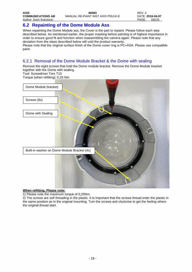
6.2 Repainting of the Dome Module Ass When repainting the Dome Module ass, the Cover is the part to repaint. Please follow each step described below. As mentioned earlier, the proper masking before painting is of highest importance in order to ensure good fit and function when reassembling the camera again. Please note that any deviation from the steps described below will void the product warranty. Please note that the original surface finish of the Dome cover ring is PC+ASA. Please use compatible paint.
6.2.1 Removal of the Dome Module Bracket & the Dome with sealing Remove the eight screws that hold the Dome module bracket. Remove the Dome Module bracket together with the Dome with sealing. Tool: Screwdriver Torx T10 Torque (when refitting): 0,25 Nm
When refitting, Please note: 1) Please note the maximum torque of 0,25Nm. 2) The screws are self threading in the plastic. It is important that the screws thread enter the plastic in the same position as in the original mounting. Turn the screws anti-clockvise to get the feeling where the original thread start.
Dome Module bracket)
Screws (8x)
Dome with Sealing
Built-in washer on Dome Module Bracket (4x)

AXIS 66583 REV: 2 COMMUNICATIONS AB MANUAL RE-PAINT INST AXIS P551X/-E DATE: 2016-04-07
Author: Sven Svensson PAGE: 19(23)
- 19 -
6.2.2 Removal of the dome sealing The dome sealing ring is easilly removed by hand from the cover.
Dome sealing ring
Cover

AXIS 66583 REV: 2 COMMUNICATIONS AB MANUAL RE-PAINT INST AXIS P551X/-E DATE: 2016-04-07
Author: Sven Svensson PAGE: 20(23)
- 20 -
7 APPENDIX: Assembly drawings and overview of products
7.1 Assembly drawings of P551X-E series
7.1.1 Main Assembly

AXIS 66583 REV: 2 COMMUNICATIONS AB MANUAL RE-PAINT INST AXIS P551X/-E DATE: 2016-04-07
Author: Sven Svensson PAGE: 21(23)
- 21 -
7.1.2 Weather Shield Assembly
7.1.3 Dome Module Assembly

AXIS 66583 REV: 2 COMMUNICATIONS AB MANUAL RE-PAINT INST AXIS P551X/-E DATE: 2016-04-07
Author: Sven Svensson PAGE: 22(23)
- 22 -
7.2 Assembly drawings of P551X series
7.2.1 Main Assembly
7.2.2 Dome Module Assembly

AXIS 66583 REV: 2 COMMUNICATIONS AB MANUAL RE-PAINT INST AXIS P551X/-E DATE: 2016-04-07
Author: Sven Svensson PAGE: 23(23)
- 23 -
8 Revision History
REVISION DATE AUTHOR DESCRIPTION R1 April 7, 2016 Sven Svensson First Revision
R2 April 7, 2016 Sven Svensson Updated Table of content


![Leo Strauss - ''Re-Education of Axis Countries Concerning Jews'' [1943]](https://static.fdocuments.in/doc/165x107/55cf8e1f550346703b8ecda7/leo-strauss-re-education-of-axis-countries-concerning-jews.jpg)