Manual Procon 900c Rev03 - JPC Controls · PROCON MODELS 900C/RS232 TEMPERATURE CONTROLLER The...
31
PROCON MODEL 900C / RS232 TEMPERATURE CONTROLLER 10/21/02 Rev 3
Transcript of Manual Procon 900c Rev03 - JPC Controls · PROCON MODELS 900C/RS232 TEMPERATURE CONTROLLER The...

PROCON MODEL 900C / RS232 TEMPERATURE CONTROLLER 10/21/02 Rev 3


PROCON MODEL 900C/RS232 TABLE OF CONTENTS
DESCRIPTION............................................................................................................ 1 LED INDICATORS ...................................................................................................... 3 ALARM LEDS ............................................................................................................ 4 KEYS .......................................................................................................................... 5 SETUP ........................................................................................................................ 7 OPERATION............................................................................................................. 10 TUNING .................................................................................................................... 13 BACKDOOR CODE .................................................................................................. 15 SPECIFICATIONS ................................................................................................... 16 WARRANTY.............................................................................................................. 17 DRAWINGS
WIRING DRAWING #13-090017-20-00............................................................. 21
DIMENSIONS DRAWING #44-090051-10-00............................................................ 22
COMMUNICATIONS SUPPLEMENT
DESCRIPTION............................................................................................................ 1 KEY COMMAND......................................................................................................... 3 READ COMMAND ...................................................................................................... 4 STATUS COMMAND .................................................................................................. 5 WRITE COMMAND..................................................................................................... 7 UP LOAD COMMAND ................................................................................................ 8 CANCEL COMMAND.................................................................................................. 9
iii N O T I C E iii JPC CONTROLS RESERVES THE RIGHT TO MAKE CHANGES TO ITS PRODUCTS OR SPECIFICATIONS AT ANY TIME, WITHOUT NOTICE, IN ORDER TO IMPROVE THE DESIGN OR PERFORMANCE AND TO SUPPLY THE BEST POSSIBLE PRODUCT. THE INFORMATION IN THIS MANUAL HAS BEEN CAREFULLY CHECKED AND IS BELIEVED TO BE ACCURATE. HOWEVER, NO RESPONSIBILITY IS ASSUMED FOR INACCURACIES.

PROCON MODELS 900C/RS232 TEMPERATURE CONTROLLER
The Model 900C/RS232 is a Microprocessor based Controller/Timer. It monitors temperature utilizing a Type J thermocouple sensor and controls bath temperature with a standard three mode (PID) control scheme, with anti-reset windup. Numerous status and alarm functions are incorporated to monitor various system parameters. A Timer with count- thru and pre-warn is integrated into the system. The following are highlights of some of the main features:
* USES TYPE J THERMOCOUPLES * THERMOCOUPLE COLD JUNCTION COMPENSATION * LIQUID LEVEL SENSOR INTERLOCK * HI LIMIT CIRCUITRY INDEPENDENT OF MICROPROCESSOR * BI-DIRECTIONAL TIMER * ACCESS CODE PARAMETER PROTECTION * EEPROM PARAMETER MEMORY * AUDIO ALARM/ANNUNCIATOR * ALL PARAMETERS SET IN SOFTWARE-NO POTS OR SWITCHES * WET STATION ENCLOSURE * BRIGHT FOUR DIGIT LED DISPLAY * SMOOTH FACE CONSTRUCTION
The Base 900 Controller has two variants, the main difference between them being line voltage. The chart below shows the differences between the controllers.
MODEL NUMBER LINE VOLTAGE
HEATER
CONTROL
RS232
900CA/RS232
24 VAC
Pilot Duty
YES
900CB/RS232
120 VAC
Pilot Duty
YES
900CC/RS232
208 VAC
20 Amp
YES
The 900CA & CB Model has two Pilot Duty Solid State outputs which drive a heater load. One is to run an external solid state relay. The other is designed to run a mercury relay coil. The 900CC model has a built-in 20 amp, photo isolated, solid state power controller that is used to control the heater. This allows the microprocessor to maintain the most accurate temperature possible without any concern about excess cycling. Both power controllers contain a zero cross detection scheme. This insures that no RFI (Radio Frequency Interference) is generated when the load is switched on and off.

- 2 -
A feature of the standard controllers is the ability to interface to a host computer via an RS232 Serial Communications port. (See Communications Section) An independent high limit circuit is provided. It is powered by an isolation transformer that draws power from the primary side of the master relay. The sensor is a Type J thermocouple. This circuit shuts off the internal master relay should an over temperature condition occur. Twelve discrete LEDs are utilized to indicate system and display status as well as annunciate various alarms. A 12 key membrane switch is incorporated in the facepanel to allow for user setup and adjustment of the system, plus full Timer control. Two numeric displays are utilized to allow the viewing of both the process temperature and the Timer simultaneously. Additionally, each of the displays has multiple diagnostic and setup functions that may be activated by the keyboard or by the microprocessor during various setup and alarm conditions. The microprocessor section consists of two circuit boards, one for display and the other for control. The control board contains two transformers and provides the isolated DC supplies (+5 and +12 volts) necessary to run the system. In addition, it contains an instrumentation amplifier, A/D converter, EEPROM memory and the microprocessor. The display board contains all of the seven segment and LED displays as well as the audio transducer.

- 3 -
LED INDICATORS
The six primary status modes are indicated by LEDs on the faceplate and are marked NORMAL, HOLD, ALARM, PROG, HEAT and DRAIN. NORMAL - This mode is the NORMAL condition for the system. It indicates that the system is operating within the defined parameters. HOLD - This mode is a STANDBY condition for the unit. It allows all normal monitoring and timing functions, but disables the heater. NOTE: For safety, the unit always starts up in this mode initially or after a power failure. When in this mode, the process display reads >Hold=. SETUP - This is the Programming mode. When in this mode, the 'SETUP' key causes the controller to step through the parameters. ALARM - The various alarm conditions are activated by many sources and annunciated by both the displays and audio tone. The mode indicator shows that an alarm has occurred and that the system is still performing under the special conditions required by that alarm. The only way to exit this mode is to clear the alarm. HEAT - This LED is illuminated whenever the heater is on. Note that when the unit is near the setpoint, the LED will continually cycle on and off. DRAIN - This LED is illuminated whenever the DRAIN relay is active.

- 4 -
ALARM LEDS
There are six alarm LEDs. They are essentially visual annunciators of system malfunctions. The six LEDs are SYSTEM, SENSOR, H LIMIT, H TEMP, L TEMP, and L LEVEL. SYSTEM - this alarm is a catch-all indicator for the miscellaneous diagnostics. An example would be the malfunction of the EEPROM SAVE routine. This would simply indicate to the user that something has gone wrong and he should either repeat the command or reset the unit. SENSOR - This indicates that the sensor is either open or not connected. Special circuitry has been incorporated to monitor the sensor for an open circuit. The processor continually monitors the input and if it detects an open sensor, it shuts off the heater output and activates the >SENSOR= alarm. The process display will alternately flash the temperature and >OP= for open sensor. H LIMIT - This is the >High Limit= alarm. This LED is wired directly to the high limit circuit and lights whenever the high limit turns the master relay off. Since it is powered by the high limit power supply it remains on even after the master relay has de-energized and has shut the controller off. H TEMP - This alarm indicates that the process temperature exceeds the high alarm setpoint. When activated, the process display alternately displays the process temperature and the code >HI=. L TEMP - The >Low Temp= alarm acts much like the >High Temp= alarm, except it compares the process temperature to the low alarm setpoint. If the process temperature drops below the setpoint once it has initially come out of the warmup mode, this alarm will be activated. In this case, the code >LO= is alternately flashed with the process temperature. L LEVEL - This alarm indicated that there is an open circuit at the Liquid Level input. This alarm typically monitors a Liquid Level switch. When activated, the code >LL= is alternately displayed with the process temperature.

- 5 -
KEYS SAVE - This key is only active in the SETUP mold and is used to permanently save the system parameters. SETUP - This key is used to put the system into the SETUP mode and once in that mode, advance through the parameters. Depressing the key once will place the unit into the SETUP mode. (Note: if the access code protection is selected, an additional step is required, see Access Code). Depressing the key after entering the SETUP mode will allow the user to scroll through the setup parameters. SIL - This key is provided to allow for the elimination of the audio portion of the alarm as well as the portion of the alarm display that effects the process display. This essentially allows the unit to be returned to a functional condition where setpoints can be examined and reset without the interference of the special alpha displays. However, the alarm status and annunciator LEDs continue to flash to indicate the alarm and where applicable, the output to the heater is turned off to protect the equipment from any potential damage. RETURN - This key is a multifunction key whose function varies with the current system mode.
SETUP MODE - When in the SETUP mode, this key exits that mode without saving the stack parameter values.
HOLD MODE - When in the HOLD mode, this key will exit that mode.
UP - In the SETUP mode, depressing the UP key will cause the display to advance. Depressing the key once and releasing will allow the accurate setting of the least significant digit. Holding the key down will activate the automatic, rapid incrementing of the display. DOWN - In the SETUP mode, depressing the DOWN key will cause the display to decrease. Depressing the key once and releasing will allow the accurate setting of the least significant digit. Holding the key down will activate the automatic, rapid decrementing of the display. START - This key is used to activate the Timer. It will start the system, if it is reset or it will continue, if the Timer has been placed in the HALT mode. (See STOP/RESET).

- 6 -
STOP/RESET - This is a multifunction key whose function varies with the current system mode.
SETUP MODE - If the Timer is running, depressing STOP/RESET will stop the count and place it in the HALT mode.
HOLD MODE - If the Timer is in the HALT mode, depressing this key will reset the Timer in preparation for the next run.
HOLD - This key will put the unit into the HOLD mode. It disables the heater output. This mode is exited by either depressing the RETURN key or a second depression of the HOLD key. Note: for safety, the unit always starts up in this mode initially or enters it after a power failure. When in this mode, the timer display reads HOLD. VIEW - This key, when depressed, displays the process setpoint and clock setpoint. This key when held down, along with the UP and DOWN keys will change the Clock Setpoint without entering the SETUP mode. DRAIN - This key is used to start the DRAIN function. PWR - This key toggles the internal electronic latch and master relay. It turns the main power to the controller ON and OFF.

- 7 -
SETUP
The SETUP mode is entered by depressing the SETUP key. While in this mode, the SETUP key is used to step through the parameters. The following is a listing of the Code prompts that will appear in the display, when in the SETUP mode. The code will alternately flash with the selected value to indicate to the user the parameter that is currently viewed or set.
CODE DESCRIPTION
CS Clock Setpoint (Min:Sec) PA Pre-Alarm Offset PS Process Setpoint IS Injection Setpoint HI High Alarm Setpoint LO Low Alarm Setpoint DR Drain/Aspirate Setpoint DP Drain/Aspirate Period AC Access Code Cr Cycle Rate Pb Proportional Band rE Reset rA Rate CA Calibration CD Clock Direction RL Relay Logic
CODE SETTING RANGE
CS 0:00 to 99:59 Minutes: Seconds PA :00 to :59 Seconds PS 0.0 to 199.9 Degrees C. IS 0.0 to 199.9 Degrees C. HI 0.0 to 199.9 Degrees C. LO 0.0 to 199.9 Degrees C. DR 0.0 to 199.9 Degrees C. DP 0:00 to 99:59 Minutes: Seconds AC 0 to 9999 CR 0 to 19 Seconds Pb 0 to 19.9 Degrees C. RE 0 to 19.9 Minutes RA 0 to 19.9 Minutes CA + or - 9.9 Degrees C. CD UP/DN (Up or Down) RL 0 = During, 1 = After, 2 = Injector

- 8 -
CS - The >Clock Setpoint= determines the duration of the Timer period. Depending on the >CD= parameter, the Timer will either count up to the desired setting or countdown from the desired setting. PA - The >Pre-Alarm= is the time at which an audio warning will begin prior to the Timer period being completed. Its purpose is to alert the operator to the fact that the Timer period has almost elapsed. The audio tone will cycle ON and OFF from the beginning of this period until the end of the Timer period. PS - This is the Process Setpoint for the system. It is the target temperature for the 3 Mode PID algorithm. IS - This is the Injector Setpoint. This parameter only appears in the stack when RL is set to 2. HI - This is the High Temperature Alarm Setpoint. The Process Temperature is continually compared with this setting and if the Process Temperature exceeds this setpoint, a High Temperature alarm is activated. LO - This is the Low Temperature Alarm Setpoint. If the Process Temperature falls below this setpoint, a Low Temperature Alarm will activate. DR - This is the DRAIN setpoint. The DRAIN function will not initiate if the Process Temperature is above this setting. DP - This is the DRAIN period. This is the time the DRAIN relay will be active in a DRAIN function. AC - The Access Code is the number that must be matched to allow entry into the Programming mode. This number may be changed at any time, but a note should be kept of its value. If set to >0=, this function is eliminated. Cr - This parameter sets the CYCLE RATE for the system. Since the controller is a standard proportional time base unit, the CYCLE RATE essentially sets the rate at which the output will cycle ON and OFF. Note that the amount of time that the output is on during each period is controlled to match the heat requirements of the system. rE - The RESET parameter for the heating mode sets the Integration time for the second mode in the three mode control scheme. If this parameter is set to 0.0, the RESET function is eliminated. rA - The RATE function for the heating mode sets the Differentiation constant for the third mode of the three mode control scheme. If this parameter is set to 0.0, the RATE function is eliminated. CA - This is the digital calibration for the process sensor. It provides a direct digital offset to the process temperature.

- 9 -
CD - The >Clock Count Direction= allows the user to program the direction in which the Timer will count. RL - The >Relay Logic= will determine whether the relay will be on during the Timer period or after the Timer period, or used as an >Injection Relay=. The SAVE key and RETURN key will exit the SETUP mode. When the SAVE key is used the stack parameters will be saved to the EEPROM memory. This is a permanent (10-year minimum life) memory that does not require battery backup. Using the RETURN key will exit the SETUP mode without saving the parameter values to the EEPROM.

- 10 -
TIMER - After the Timer has been programmed in the SETUP mode, a Timer period can be run by depressing the START key. The following is a description of Timer operation with various system settings. DOWN COUNT TIMER - The Timer will begin to countdown. The Timer will continue this process until it reaches the pre-alarm time setting. At this point, an audio tone that has a 50/50 duty cycle and a 1 second period will sound. Once the unit has counted down to 0:00, the audio will change to a continuous tone and the display will begin to flash. If the timer is not stopped, it will begin to count back up, accumulating the time that has elapsed. UP COUNT TIMER - The Timer will begin to count up. It will continue this process until it reaches the set time minus the pre-alarm setting. At this point, an audio tone that has a 50/50 duty cycle and a 1 second period will sound. Once the unit has counted up to the preset time, the audio will change to a continuous tone and the display will begin to flash. If the timer is not stopped, it will reset to zero and count back up, accumulating the time that has elapsed. Depressing the STOP/RESET key will stop the Timer and freeze the display. Depressing the STOP/RESET key for a second time will reset the Timer for another cycle. If in the DOWN COUNT mode, the pre-programmed setpoint will be inserted in the display. If in the UP COUNT mode, the display will be set to 0:00. In both cases, the Timer is then ready for another cycle. QUICKSET TIMER - This feature allows the Clock Setpoint parameter to be set without going into the SETUP stack. This is done by depressing and holding the VIEW key. This will activate the VIEW function and place the Clock Setpoint in the Timer Display. While holding this key, the UP and DOWN keys may be utilized to change the setpoint. It should also be noted that the main function of the QUICKSET feature is to temporarily change the Clock Setpoint being used. Therefore, when QUICKSET is used, the value to which the Clock Setpoint has been changed will not be stored in the EEPROM memory without first accessing the PROGRAM mode, and then performing a EEPROM SAVE, using the SAVE key. TEMPERATURE - This system may operate in either a one, two or three mode configuration. Setting the RATE or RESET variables to 0.0 will eliminate the respective function. It should be noted that the RATE and RESET settings adjust the sampling period directly in tenths of minutes. Thus, smaller numbers create more rapid sampling. CALIBRATION - The calibration (CA) adjustment allows the elimination of various sensor and system errors. Thermocouple sensors are manufactured within a specific tolerance. The tolerance may lead to a difference between the actual bath temperature and the temperature displayed. This error coupled with the differential error caused by sheathing the sensor in materials such as Teflon may cause a difference in the actual bath temperature and display temperature. This can simply be corrected by monitoring the bath temperature and utilizing the offset to add or subtract the appropriate number of degrees to bring the display into compliance with the actual bath temperature.
OPERATION

- 11 -
ACCESS CODE - In some cases, it may be desirable to restrict access to the SETUP mode. An Access Code system is incorporated. If the Access Code is set to >0000=, the function is eliminated and the system operates as previously described. The code is any number from 1 to 9999, as programmed into the system by the customer's authorized personnel. Once this code is entered, any attempt to enter the SETUP mode will cause 'CODE' to appear in the Timer display. The UP and DOWN keys are then used to enter the Access Code. Once the proper code has been selected, the user simply depresses the SETUP key to gain entry into the SETUP parameters. ALARMS - All of the alarms activate the audio tone as well as the alarm status LED and the individual alarm annunciator. The tone and the LEDs alternate on and off to draw attention to the alarm. As has been noted above, many of the alarms have additional visual displays to further define or draw attention to them. The ALARM SILENCE key is provided to allow for the elimination of the audio portion of the alarm as well as the portion of the alarm display that effects the process display. This essentially allows the unit to be returned to a functional condition where setpoints can be examined and reset without the interference of the special alpha displays. However, the alarm status and alarm annunciator LEDs continue to flash to indicate the alarm and, where applicable, the output to the heater is turned off to protect the equipment from any potential damage. DRAIN - The DRAIN function provides a Timed, Temperature Interlocked DRAIN Cycle. In the programming parameters, the user may program the temperature (DR) above which the DRAIN function will not work. Also, the length of the DRAIN Period (DP) may be programmed. The DRAIN key may be used to start the DRAIN Cycle and also stop it. If the cycle is not mechanically stopped before the Timer elapses, the Timer will automatically stop the DRAIN. To help prevent an accidental Drain/Aspiration, a dual key entry is necessary to initiate the cycle. When the DRAIN Key is first depressed, the unit will acknowledge with 4 beeps. The key must then be depressed for a second time for the cycle to be activated. If the initial depression was in error, the Return key may be depressed to cancel the DRAIN request.

- 12 -
AUX RELAY - The unit is provided with an Auxiliary Relay. The logic for this relay is selected by the 'RL' parameter in the setup stack. The relay will respond as follows: RL=0 (During) - This configures the auxiliary relay as a Timer relay. It will be active for the period that the Timer is active. It will activate when the Timer is started and deactivate when the Timer has completed its count. The relay is not active in over count. RL=1 (Done) - This configures the auxiliary relay as a Timer relay. It will activate at the completion of the Timer cycle. It will remain active until the Timer is reset. RL=2 (Injector) - This configures the auxiliary relay as an injector relay. The 'IS' (Injection Setpoint) parameter will appear in the setup stack. The relay will be active whenever the process temperature is higher than the 'IS' setpoint.

- 13 -
TUNING
The control scheme used in this controller is a standard PID system with anti-reset windup. This section will briefly review PID control as it relates to this system. It should be noted that this discussion specifically relates to this device and may be somewhat different than other systems. The terms PID and 3 Mode are interchangeable. The first mode of control, >P= (Proportional) refers to the basic control scheme. The concept is that the controller will determine the percentage of heat required by the system and adjust the average power input to the heater to balance the system. The power to the heater is either fully on or fully off. The proportioning is obtained by ratioing the amount of time 'ON' to the amount of time 'OFF'. Thus proportional control in this application is more correctly termed Time Proportioning. The Cycle Rate (CR) setting is used to determine the rate at which the heater power is turned on and off. The proportioning of the output power is accomplished by varying the percentage of time that the unit is on during the period. For example, if CR = 10, then the unit will cycle on and off once every 10 seconds. If the process has determined that the system requires only half of the full power output of the heater to maintain a specific temperature, the output will be ON for 5 seconds and OFF for 5 seconds in a continuous cycle. As the heat requirement varies, this percentage will increase to slightly longer periods ON, such as 5.1 seconds ON, 4.9 seconds OFF. The opposite is true for decreasing heat load requirements. Thus, when the system is at or near the setpoint, the HEAT LED in the status box will continually flash to indicate the time proportioning of the heater. To compute the required percentage of >ON= time, the system utilizes the Proportional Band (PB) as set in the programming mode. It is over this band that the output will vary from 0 to 100%. If for example, the setpoint is at 100 degrees C. and the proportional band is set at 10 degrees C., the controller will time proportion the output from 100% to 0% when the process temperature varies from 90 to 100 degrees C. When the process temperature is at 90 degrees C. and less, the output will be fully on, between 90 and 100 degrees C. the output will time proportion from 100% down to 0%. At any temperatures above 100 degrees C., the output will be fully off. At this point it is important to note that we are discussing systems in which the Rate and Reset functions are not used. Rate and Reset will cause a shifting in the Proportional Band and vary the percentages just discussed. However, Rate and Reset do not affect the basic theory, only the position of the Proportional Band at any moment in time. Now we will tie the Proportional Band and Cycle Rate together in the example used above. We had a cycle rate of 10 seconds with a Proportional Band of 10 degrees C. and a setpoint of 100 degrees C. When the process temperature is 96 degrees, we will note that it is 40% into the Proportional Band. Based on this position we require 40% heater output, with the 10 second cycle rate, this means that the heater will be ON for 4 seconds and OFF for 6 seconds.

- 14 -
Obviously, a proportional control requires a certain degree of error to have the heat on. Therefore, in the example just given if we find that only 10% of the heat is required to maintain the desired temperature. The unit will cycle 1 second ON and 9 seconds OFF and the temperature will stabilize at 99 degrees. This is not the desired 100 degrees. The difference between the two is termed Droop. Droop is the difference between the setpoint and the control point in a proportional system. To remove this Droop, we need the 2nd mode. This is the I (Integral) mode or commonly termed Automatic Reset Mode. The program calculates the difference between the current process temperature and the desired setpoint and mathematically corrects the system to compensate for this error. How often this is done, is based on the parameter that is programmed in the >RE= (Reset Adjustment). Anti-Reset Windup is a special feature incorporated in the software that locks out the Reset function when the system is outside of the Proportional Band. Obviously, if the system were automatically adjusting the DROOP before the system was nearing stability, large errors would occur. Anti-Reset Windup is used to eliminate such potential errors. The third mode in the PID scheme is the D (Derivative) mode commonly referred to as RATE. When a system has large step changes in heat requirements, it may require this third mode to compensate for such changes. Its primary function is to eliminate overshoots as the temperature is stabilizing. It controls the rate of change of the temperature when large temperature fluctuations occur. On systems where overshoot is not a problem, the rate function may be eliminated for simplicity. In general, bath control requires reset on all occasions. Rate may not be required and should be set to zero, unless overshooting occurs.

- 15 -
BACKDOOR CODE
A special code has been incorporated into the software to insure factory access to all functions no matter what the customer has done with the access codes. This code is 900. MANUAL REVISIONS
Revision # Eng. # Program # Revision Made
Rev 0 DT900CA/RS232 DT900CNA Origination
DT900CB/RS232 DT900CC/RS232
Rev 1 DT900CA/RS232 DT900CNB Misc. Software Fixes DT900CB/RS232
DT900CC/RS232
Rev 2 DT900CA/RS232 DT900CNB Misc. Changes DT900CB/RS232
DT900CC/RS232
Rev 3 DT900CA/RS232 DT900CNB Added New Drawing DT900CB/RS232
DT900CC/RS232

- 16 -
SPECIFICATIONS
MODEL 900C/RS232 TEMPERATURE CONTROLLER RANGE 0.0 - 199.9 Degrees C. (Temperature) RESOLUTION 0.1 Degrees C. (Temperature) NOISE REJECTION NMR - 60 db @ 60 HZ CMR -120 db @ 60 HZ RANGE (Time) 0:00 - 99:59 Min:Sec RESOLUTION (Time) 1 Sec. MEASURING TIME 4 Conversions/Sec DISPLAY Eight, 0.56 Inch High, Seven Segment, LED Uniplanar numerals. Twelve Discrete LEDs (Red, Green, Amber) ANNUNCIATOR Audio Tone, ~ 3200 HZ SETUP MEMORY EEPROM, All Parameters MEMORY RETENTION 10 Years w/o Power SENSOR Standard - Type J Thermocouple, Cold Junction Compensation, Up Scale Break Protection. CONTROL PID with Anti-Reset Windup. ADJUSTMENT Cycle Rate: 0 - 19 Sec. Proportional Band: .1 - 19.9 Deg. C
Reset (Integral): .1 - 19.9 Min. Rate (Derivative): .1 - 19.9 Min.
Calibration Offset: + 9.9 Deg. C OPERATING RANGE 0 to 50 Degrees C STORAGE RANGE -40 to 60 Degrees C

- 17 -
CONSTRUCTION Enclosure - Kydex, Black Face - Lexan, Back Printed SIZE 8 1/4 x 6 x 5.25 inches (HxWxD) 210 x 152 x 133mm WEIGHT < 4 Lbs. (1.8 kg) CONNECTION Rear, Screw-Type, 3/8 Inch Centers;
T/C - Miniature, Type J, Jack. Communications-DB9 (Optional) OUTPUT Heater: SSR, Optically isolated,
900CC Only: Zero cross, 20 amp, 208 VAC 50/60 HZ
SSR Drives: 20mA, 12 VDC (provided) Relay: 1 HP, 240 VAC POWER 900CA - 11 VA, 24 VAC + 10%,50/60 HZ
900CB - 11 VA, 120 VAC + 10%,50/60 HZ 900CC - 11 VA, 208 VAC + 10%,50/60 HZ
LIMITED WARRANTY WARRANTY: JPC CONTROLS WARRANTS ITS NEW PRODUCTS TO BE FREE FROM DEFECTS IN MATERIALS AND WORKMANSHIP UNDER THE SERVICE FOR WHICH THEY ARE INTENDED. THIS WARRANTY IS EFFECTIVE FOR TWELVE MONTHS FROM THE DATE OF SHIPMENT. EXCLUSIONS: THIS WARRANTY IS IN LIEU OF ANY OTHER WARRANTY EXPRESSED OR IMPLIED, INCLUDING, BUT NOT LIMITED TO ANY IMPLIED WARRANTY OF MERCHANTABILITY OR FITNESS FOR A PARTICULAR PURPOSE. JPC CONTROLS IS NOT LIABLE FOR ANY INCIDENTAL OR CONSEQUENTIAL DAMAGES. NO PERSON OTHER THAN AN OFFICER IS AUTHORIZED TO GIVE ANY OTHER WARRANTY OR ASSUME ANY LIABILITY. REMEDIES: THE PURCHASER'S SOLE AND EXCLUSIVE REMEDY SHALL BE: (1) THE REPAIR OR REPLACEMENT OF DEFECTIVE PARTS OR PRODUCTS, WITHOUT CHARGE. (2) AT THE OPTION OF JPC CONTROLS, THE REFUND OF THE PURCHASE PRICE.

COMMUNICATIONS SUPPLEMENT
This supplement contains information relating to the RS232 communications interface for the Model 900CN/900CNA Temperature Controllers. This allows the user to have direct access to the Controller via a standard RS232 link. Through this serial link, all of the standard functions of the Controller may be activated, tested and adjusted. Since this unit is a Controller, it does not handle a great deal of data. Therefore, the link has been optimized to allow the user, through very simple instructions, to control and interrogate the unit. Ten 'key' commands allow the user to instruct the Controller to perform all of its normal operations. However, only a couple of these are actually required for computer operation. The remainder are provided, but are not often used, since these keys are utilized in programming. The serial link has direct access to the programming stack through the 'READ', 'WRITE', 'UP LOAD' and 'DOWN LOAD' commands without using 'key' commands. Utilizing these commands, the serial link can interrogate or overwrite any or all of the items in the PROGRAM stack. The basic status conditions for the Controller are accessed through 4 bytes. These bytes may be read out at any time using the 'STATUS' command. The Controller may be hooked to any standard terminal or computer system via the DB9 connector on the back panel. The pin out follows the standard IBM DB9 configuration. Therefore, it may be wired directly to an IBM PC/AT or its equivalent. The link is fixed at 9600 baud, 8 bit, 1 stop and 1 start bit, no parity. This link only requires 3 leads to function. As viewed from the Controller, Pin 5 is the 'Signal Ground', Pin 3 is 'Receive Data' and Pin 2 is 'Transmit Data'. The internal ACIA utilizes a full duplex interrupt driven transmission scheme. Thus, the unit may receive and transmit simultaneously, as well as continue to perform its normal functions. Therefore, the Controller may be interrogated even though it is performing its program.

-2-
The Protocol for the serial link consists of 7 basic commands:
K – KEY S – STATUS R – READ W – WRITE D – DOWN LOAD U – UP LOAD X – CANCEL (CLEAR)
All commands will be prefixed by one of these 7 letters. The data format is standard ASCII and all data, with the exception of the Status Bytes are BCD values. The Status Bytes are transmitted in ASCII as hexadecimal, since they contain bit information. UP LOAD and DOWN LOAD are the only group commands. They each have a specific format and a specific number of bytes of information. They are structured to DOWN LOAD all of the programming information at one time or READ the complete programming stack. All of the rest of the commands are structured to handle the data one byte at a time. The following is a breakdown of each of the commands and the way they are accessed. It should be noted that the format allows for the unit to be hooked directly to a dumb computer terminal. This can be very useful in checkout. The unit will echo all characters that are typed to it. When used with a terminal, this will provide the appropriate display. When used with a computer system, this will provide direct feedback of the fact that unit has accepted the data. All commands are completed with a carriage return from the computer. With the exception on the CANCEL command (X), all commands will be acknowledged by a carriage return, line feed ($0D,$0A).

-3-
KEY COMMAND
The KEY COMMAND allows the user to instruct the Controller just as would be done by depressing the Face Panel keys. The exact operation and sequence for these keys is covered in the Controller manual. This description will simply indicate how the link may be used to send these key functions. The command is entered as a letter followed by 2 numbers, followed by a carriage return: K01(Return) The ‘K’ indicates that this is to be a KEY command. The ‘01’ indicates the KEY number and the ‘Return’ activates the command. The following is a listing of the key numbers:
KEY NUMBER KEY
11 DOWN 11 SAVE 11 SILENCE 11 VIEW 11 START 11 UP 11 SETUP 11 RETURN 11 HOLD 11 STOP/RESET 11 DRAIN
When a KEY command is sent, the Controller will echo each of the characters and acknowledge with a carriage return line feed, once the command is entered. If an invalid command is detected, it will simply be ignored, although it will acknowledge the fact that the command has been received.

-4-
READ COMMAND
The READ command is utilized to read from the Controller any of the program data. The format for the command is essentially the same as the KEY command. R07(Return) The ‘R’ indicates to the Controller that the command is to be a READ command. The next two digits indicate the information that is to be read. The carriage return indicates that the command is to be activated. The following is a listing of the data locations that may be read:
DATA LOCATION DESCRIPTION
18 CS 18 PS 18 HI 18 LO 18 AC 18 DR (READ ONLY) 18 UNUSED 18 PA 18 CR 18 PB 18 RE 18 RA 18 RL 18 IS 18 DP 18 CD (1=UP, 4=DOWN) 18 PROCESS TEMPERATURE 18 REMAINING TIME
It should be noted that while most of the values will read out directly as they appear on the unit, the Time Values will display in Minutes and Seconds, but will read out in seconds only. Therefore, the clock setpoint on the unit may be programmed for 5:00 (Minutes:Seconds). The data that is read from the unit will come out as 0300 seconds. All data is returned in ASCII format with 4 BCD characters. When the controller displays information, such as the Proportional Band in tenths of degrees C., the data that is returned will be in tenths of degrees. For example, 10.0 degrees C. will be transmitted as 0100. The user should refer to the Controller Manual to determine the exact meaning of each of these readings.
-5-
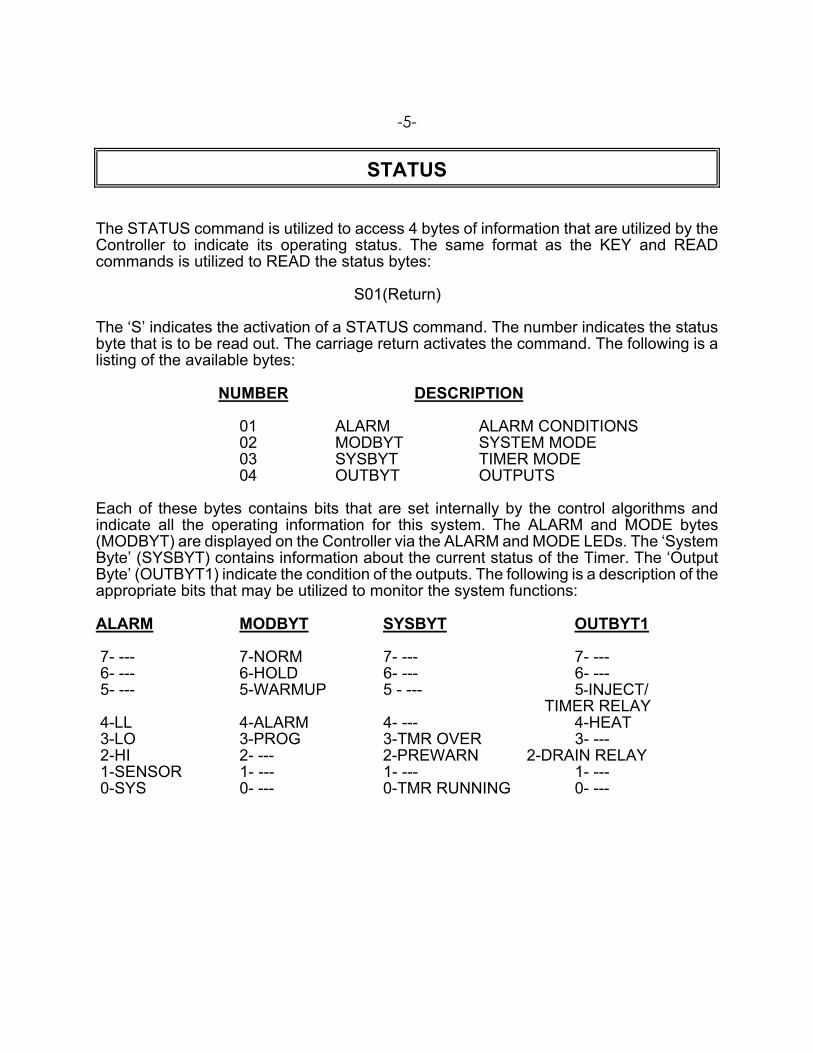
STATUS
The STATUS command is utilized to access 4 bytes of information that are utilized by the Controller to indicate its operating status. The same format as the KEY and READ commands is utilized to READ the status bytes: S01(Return) The ‘S’ indicates the activation of a STATUS command. The number indicates the status byte that is to be read out. The carriage return activates the command. The following is a listing of the available bytes:
NUMBER DESCRIPTION
01 ALARM ALARM CONDITIONS 02 MODBYT SYSTEM MODE 03 SYSBYT TIMER MODE 04 OUTBYT OUTPUTS
Each of these bytes contains bits that are set internally by the control algorithms and indicate all the operating information for this system. The ALARM and MODE bytes (MODBYT) are displayed on the Controller via the ALARM and MODE LEDs. The ‘System Byte’ (SYSBYT) contains information about the current status of the Timer. The ‘Output Byte’ (OUTBYT1) indicate the condition of the outputs. The following is a description of the appropriate bits that may be utilized to monitor the system functions: ALARM MODBYT SYSBYT OUTBYT1 7- --- 7-NORM 7- --- 7- --- 6- --- 6-HOLD 6- --- 6- --- 5- --- 5-WARMUP 5 - --- 5-INJECT/ TIMER RELAY 4-LL 4-ALARM 4- --- 4-HEAT 3-LO 3-PROG 3-TMR OVER 3- --- 2-HI 2- --- 2-PREWARN 2-DRAIN RELAY 1-SENSOR 1- --- 1- --- 1- --- 0-SYS 0- --- 0-TMR RUNNING 0- ---

-6-
The meaning for each of the ALARM and MODE LEDs is covered in the Controller Manual. The SYSTEM BYTE indicates whether the Timer is running or not, and whether it is in the OVERTIME or PREWARN modes. The OUTPUT BYTE contain both positive and negative logic bits. For those bits that are unmarked, a '1' indicates that the output is ON. For those bits that are marked with a not (GGGGG), the outputs are on when the bit is '0'. Also, it should be noted that many of the undefined bits are used internally and therefore may be either '1' or '0' at any given reading. These bytes require data transmission in a hexadecimal format. The actual data is sent as an ASCII character, but its meaning is translated in hexadecimal to determine the appropriate bit pattern. For example, the ASCII transmission of $31,$30 would translate to a hex reading of 10, which would indicate for the ALARM BYTE that a low alarm condition existed. After the carriage return, the Controller will acknowledge with a carriage return line feed and then send the two ASCII characters that indicate the hex representation for the appropriate bit pattern requested.

-7-
WRITE
The WRITE command allows the user to overwrite most of the information in the programming stack. The calibration value is not accessible. It should be noted that while this information may be over written, it will not be permanently saved in the controller without first accessing the SETUP mode and then activating the SAVE command via the keys. If the values written are to be permanently saved in the controller’s EEPROM memory, after all changes have been made, a K07 (SETUP) followed by a K02 (SAVE) must be transmitted. If it is not desirable to have these values permanently saved, the user may simply go in and overwrite the current information for temporary use. When the system is repowered, the information that is currently stored in its EEPROM will be reinserted into the SETUP stack. The following is the format for this command: W020750 The command essentially follows the same format as all the previous commands. The ‘W’ indicates that it is a WRITE command, the next two characters indicate the location that is to be written to and the last four characters indicate the data value that is to be entered. Again, the data is in BCD and transmitted in an ASCII format. The example WRITE command would put 75.0 Degrees C. in the Process Setpoint. The data locations are the same as those covered in the READ command section. However, locations 06, 17 and 18, are READ only and may not be written to. Location 17 and 18 simply provide a Read Out for the current Process Temperature and Remaining Time.

-8-
UP LOAD
The UP LOAD command is utilized to READ all of the items in the SETUP Stack at one time. The following is the format for this command: U(Return) This is a single character command that instructs the controller to do a direct dump of the complete programming stack. The data will be transmitted as described in the READ COMMAND section with a carriage return line feed between each parameter. DOWN LOAD
The DOWN LOAD command allows the user to overwrite the complete setup stack with one command. The following is the format for this command: Dxxxxxxxxxxxxxxxxxxxxxxxxxxxxxxxxxx(Return) Where small 'x' is replaced by the data to be DOWN LOADED starting with data location 1 and running through data location 16. The Controller will echo each of the characters as it is transmitted to confirm that it has been correctly received. The data locations and the appropriate descriptions are identical to the stack shown under the READ command.

-9-
CANCEL
The CANCEL command is simply a way to reestablish proper control, should an error occur or an incorrect command be transmitted. For the most part, an incorrect command will simply be ignored and the controller will prepare for an additional command. However, a command may be canceled midstream by transmitting an 'X' (ASCII). This command does not require a carriage return, nor will it acknowledge with a carriage return. However, it will echo an 'X' to indicate that the CANCEL command has been received. The command may also be utilized as a clear and/or acknowledgment of the Controller being on line. P:\MANUALS\PROCON\Manual_Procon_900c_Rev03.doc


JPC CONTROLS
BYCHKDSCALE
OF
SHEET
DATEBYDWN
DATEQA
DATEENGAPPROVAL
PATH =
ALL DIMENSIONS ARE IN INCHES
SPECIFIEDTOLERANCES UNLESS OTHERWISE
TOP VIEW
FRONT VIEWSIDE VIEW
5.950
5.0000.187
8.250
6.000
5.450
44 10 01
MPJ NONE
1 1
PHYSICAL DIMENSIONS
090051
12/22/99
E:\CC\DT900\900CP11.SLDDRW
PROCON 900CA/CB/CC WITH RS232 CONTROLLER
102 COMPASS PT. DR. STE. D, ST. CHARLES, MO 63301 (636) 946-3300 Fax (636) 724-2492 www.jpccontrols.com