Manual Part - II-MPL Project 23 07 2012.pdf
105
Document No.: 2003-E-065-00 Date: 23.07.2012 Project : 2 x 90 TPH CFBC Boiler Customer: MEGHALAYA POWER LTD. W.O. No.: 2M0015 & 16 Issue Status: Controlled Copy – Unauthorized copying not Page 73 of 177 TITLE: COMMISSIONING & OPERATION D0 - 0 - 0 - 0 COMMISSIONING & OPERATION
-
Upload
halderkalyan9216 -
Category
Documents
-
view
25 -
download
4
Transcript of Manual Part - II-MPL Project 23 07 2012.pdf

Document No.: 2003-E-065-00 Date: 23.07.2012
Project : 2 x 90 TPH CFBC Boiler Customer: MEGHALAYA POWER LTD. W.O. No.: 2M0015 & 16 Issue Status: Controlled Copy – Unauthorized copying not
Page 73 of 177
TITLE: COMMISSIONING & OPERATION
D0 - 0 - 0 - 0 COMMISSIONING & OPERATION

Document No.: 2003-E-065-00 Date: 23.07.2012
Project : 2 x 90 TPH CFBC Boiler Customer: MEGHALAYA POWER LTD. W.O. No.: 2M0015 & 16 Issue Status: Controlled Copy – Unauthorized copying not
Page 74 of 177
TITLE: FILLING STEAM GENERATOR
D1 - 0 - 0 - 0 FILLING STEAM GENERATOR

Document No.: 2003-E-065-00 Date: 23.07.2012
Project : 2 x 90 TPH CFBC Boiler Customer: MEGHALAYA POWER LTD. W.O. No.: 2M0015 & 16 Issue Status: Controlled Copy – Unauthorized copying not
Page 75 of 177
TITLE: FILLING STEAM GENERATOR D1.1.0.0 QUANTITY OF FEED WATER
The steam generator must only be filled with degassed and de-mineralized boiler water
(feed water specification are furnished to clients elsewhere). Approximately 36 m3 of
feed water is required to fill the boiler, up to centre of steam drum.
The status of various valves of the steam generator prior to filling water should generally
be:
D1.2.0.0 FIRST TIME OR WHEN THE BOILER IS EMPTY
Sl. No.
Valve Name Condition
1. Vent valves on drum, eco, and super-heaters Open
2.
Drain valves of Superheaters, Evaporator, Economizer,
Furnace walls bottom headers, screen (i.e. evaporator drain
station)
Open
3. Valves on feed control station Close
4. All isolation and control valves of drum mountings except
isolation and control valves of one gauge glass Close
5. All valves on steam circuit Close
Furnace portion is filled usually by filling pump connections through furnace wall drain
header / Evaporator drain station. Start fill pump, open isolation and control valves on
filling pipe up to drain station and allow water to flow at the rate not exceeding approx.
20 TPH.
Close the vent valves on Economiser-I and Economiser-II soon after water flows full
throat from them. Close Economiser and evaporator drain valves.
After drum is filled and the water rises up to saturated steam header water will start
entering the super-heaters. As water starts flowing full from superheated vents close
them one by one. Thus superheated is now full of water. (This will only be required if
Boiler Hydraulic test is to be conducted).

Document No.: 2003-E-065-00 Date: 23.07.2012
Project : 2 x 90 TPH CFBC Boiler Customer: MEGHALAYA POWER LTD. W.O. No.: 2M0015 & 16 Issue Status: Controlled Copy – Unauthorized copying not
Page 76 of 177
TITLE: FILLING STEAM GENERATOR
In case, fill pumps are not available then water will have to be taken through boiler feed
pumps. Under this condition, all valves under Sl.No. (2) Stated above, have to be
necessarily "closed" before starting feed pumps. Feeding rate should be less than 20
TPH and the water should be taken in boiler through low feed line.
As the drum level reaches approximately (-) 100 mm, switch off filling pump / feed
pump. Close corresponding isolation / control valves.
D1.3.0.0 WHEN THE BOILER IS PARTIALLY FILLED (NORMAL OPERATION)
a) All drain valves are expected to be closed. Maintain same status.
b) Keep vent valves on Economiser, drum and Superheater open.
c) Valves at feed control station and spray control station are closed.
d) All valves on drum steam circuit are kept closed.
e) Valves on drum mountings are kept open except "drain" valves.
Start the feed pump and start topping up by keeping low feed line control valve crack
open (flow <20 TPH). Close vent valves on Economizer-I & II soon after water flows full
throat through them. As the water level in gauge glasses is approx. (-) 100 mmWC
close the low feed control valve and switch off the feed pump.

Document No.: 2003-E-065-00 Date: 23.07.2012
Project : 2 x 90 TPH CFBC Boiler Customer: MEGHALAYA POWER LTD. W.O. No.: 2M0015 & 16 Issue Status: Controlled Copy – Unauthorized copying not
Page 77 of 177
TITLE: START-UP CHECK LIST
D2 - 0 - 0 - 0 START-UP CHECK LIST

Document No.: 2003-E-065-00 Date: 23.07.2012
Project : 2 x 90 TPH CFBC Boiler Customer: MEGHALAYA POWER LTD. W.O. No.: 2M0015 & 16 Issue Status: Controlled Copy – Unauthorized copying not
Page 78 of 177
TITLE: START-UP CHECK LIST
D2.0.0.0 START UP CHECK LIST
Preparatory to light up of the boiler, check the following:
1. All access doors on furnace, flue, ducts, fans etc. are closed properly.
2. Water level in steam drum is around -100mm from NWL.
3. All interlocks are checked & operating satisfactorily. Do not bypass any safety
interlock.
4. All instruments and control systems are operational.
5. All auxiliary dampers are in "start up" position.
6. Sufficient start-up fuel is available.
7. Sufficient main fuel is available.
8. Sufficient feed water is available.
9. The bed level is normal and it is free from any foreign material.
10. Cooling water is switched on.
11. Compressed air is available.
12. Electric power for auxiliary equipment and control is available.
13. All fire protection system is operational.
14. Hydrostatic plugs or test gags are removed from safety valves.
15. Variable/constant load hanger supports are unlocked.
16. Slide gate on bed ash and cyclone ash drop pipes are in closed position and
operational.
17. Bottom ash, cyclone ash and fly ash handling system are fully operational.
18. Pressure gauges especially drum; temperature and level indicators are in
service.
19. Valves required in "close" position:
a) Economiser drains and vent
b) Evaporator drains and vent
c) Drum drain (IBD)
d) All water walls bottom header drains
e) Continuous blow down valves
f) Chemical dosing valve.
g) Screen inlet header drain

Document No.: 2003-E-065-00 Date: 23.07.2012
Project : 2 x 90 TPH CFBC Boiler Customer: MEGHALAYA POWER LTD. W.O. No.: 2M0015 & 16 Issue Status: Controlled Copy – Unauthorized copying not
Page 79 of 177
TITLE: START-UP CHECK LIST
20. Valves required in open position:
a) Drum vent
b) Superheater drains and vents
c) Low feed isolation and feed check valves.
d) Drum & Superheater pressure gauge isolation and control valves.
e) Direct gauge glass isolation and control valves.

Document No.: 2003-E-065-00 Date: 23.07.2012
Project : 2 x 90 TPH CFBC Boiler Customer: MEGHALAYA POWER LTD. W.O. No.: 2M0015 & 16 Issue Status: Controlled Copy – Unauthorized copying not
Page 80 of 177
TITLE: SEQUENTIAL START-UP/SHUTDOWN & BOILER SAFETY INTERLOCKS
D3 - 0 - 0 - 0 SEQUENTIAL START-UP/SHUTDOWN &
BOILER SAFETY INTERLOCKS

Document No.: 2003-E-065-00 Date: 23.07.2012
Project : 2 x 90 TPH CFBC Boiler Customer: MEGHALAYA POWER LTD. W.O. No.: 2M0015 & 16 Issue Status: Controlled Copy – Unauthorized copying not
Page 81 of 177
TITLE: SEQUENTIAL START-UP/SHUTDOWN & BOILER SAFETY INTERLOCKS
D3.1.0.0 SEQUENTIAL START-UP
Boiler auxiliaries have to be started in the following order so that safe light up is
achieved without any conflict with interlocks. Boiler is to be purged before light up from
the cold condition (cold start-up). For this purpose, a soft Timer shall be built in the
DCS, the setting of which can be adjusted. During the cold start-up, the setting of this
timer is to be set for 10 min., which is the purge cycle duration. Setting time of 10 min.
ensures about 3 volumetric changes of air in the Boiler and the air / flue gas path. This
setting has been followed in Cold Cyclone CFBC Boiler installations in Germany, which
yielded satisfactory results. This also meets NFPA requirement.
Under all condition of boiler starting it must be ensured that water level in steam drum is
approx. (-) 100 mm from NWL and coal feeders are not in operation. Also coal isolation
gates above siphon are in closed position.
D3.2.0.0 START-UP SEQUENCE
D3.2.1.0 AIR /FLUE GAS START-UP SEQUENCE
The damper positions marked ‘*’ thus below are only for starting-up of fans. The suction
and discharge dampers of ID, SA and PA fans are to be kept closed during the starting
of respective fans to isolate the system resistance. Once ID fan is started, followed by
SA fan, PA fan in a sequence, the discharge dampers of ID, SA and PA fans are fully
opened. The control dampers of SA and Tertiary Air local to the boiler are also to be
kept around 50% open. SA Fan speed is kept low i.e. about 10% of rated speed and
maintained during the light-up. Thereafter, speed of PA fan is gradually increased till the
minimum PA flow condition required for light-up is reached. The ID fan speed is slowly
increased with the VFD Control, commensurate with PA fans’ speed, basically to
maintain around (-) 30 to (-) 50 mm (may be around – 10 mm during oil firing) Furnace
draft.
Document No.: 2003-E-065-00 Date: 23.07.2012
Project : 2 x 90 TPH CFBC Boiler Customer: MEGHALAYA POWER LTD. W.O. No.: 2M0015 & 16 Issue Status: Controlled Copy – Unauthorized copying not
Page 82 of 177
TITLE: SEQUENTIAL START-UP/SHUT-DOWN & BOILER SAFETY INTERLOCKS
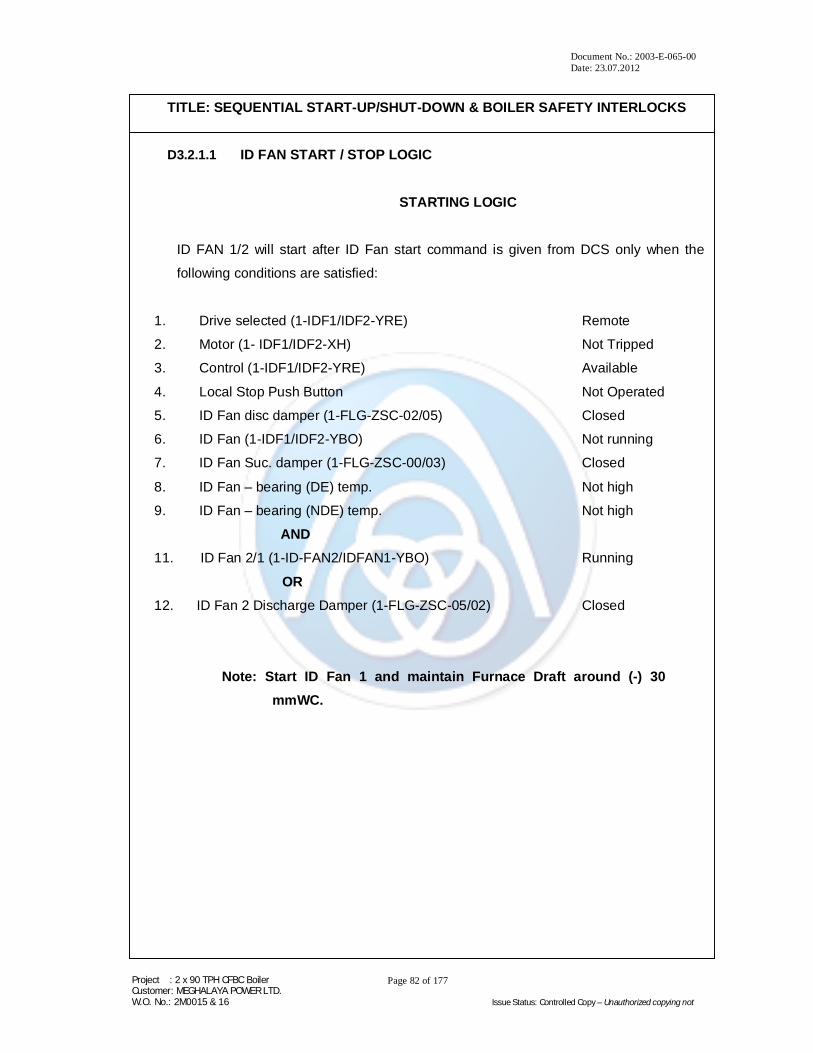
D3.2.1.1 ID FAN START / STOP LOGIC
STARTING LOGIC
ID FAN 1/2 will start after ID Fan start command is given from DCS only when the
following conditions are satisfied:
1. Drive selected (1-IDF1/IDF2-YRE) Remote
2. Motor (1- IDF1/IDF2-XH) Not Tripped
3. Control (1-IDF1/IDF2-YRE) Available
4. Local Stop Push Button Not Operated
5. ID Fan disc damper (1-FLG-ZSC-02/05) Closed
6. ID Fan (1-IDF1/IDF2-YBO) Not running
7. ID Fan Suc. damper (1-FLG-ZSC-00/03) Closed
8. ID Fan – bearing (DE) temp. Not high
9. ID Fan – bearing (NDE) temp. Not high
AND
11. ID Fan 2/1 (1-ID-FAN2/IDFAN1-YBO) Running
OR
12. ID Fan 2 Discharge Damper (1-FLG-ZSC-05/02) Closed
Note: Start ID Fan 1 and maintain Furnace Draft around (-) 30
mmWC.
Document No.: 2003-E-065-00 Date: 23.07.2012
Project : 2 x 90 TPH CFBC Boiler Customer: MEGHALAYA POWER LTD. W.O. No.: 2M0015 & 16 Issue Status: Controlled Copy – Unauthorized copying not
Page 83 of 177
TITLE: SEQUENTIAL START-UP/SHUTDOWN & BOILER SAFETY INTERLOCKS
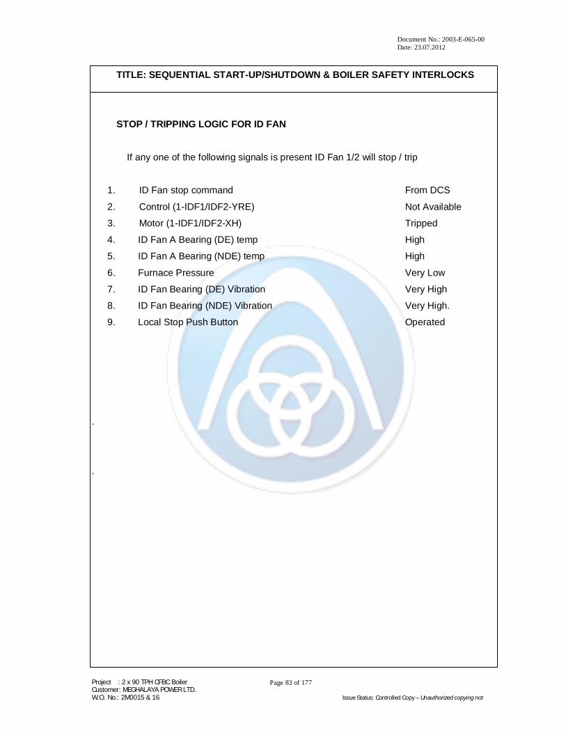
STOP / TRIPPING LOGIC FOR ID FAN
If any one of the following signals is present ID Fan 1/2 will stop / trip
1. ID Fan stop command From DCS
2. Control (1-IDF1/IDF2-YRE) Not Available
3. Motor (1-IDF1/IDF2-XH) Tripped
4. ID Fan A Bearing (DE) temp High
5. ID Fan A Bearing (NDE) temp High
6. Furnace Pressure Very Low
7. ID Fan Bearing (DE) Vibration Very High
8. ID Fan Bearing (NDE) Vibration Very High.
9. Local Stop Push Button Operated
.
.

Document No.: 2003-E-065-00 Date: 23.07.2012
Project : 2 x 90 TPH CFBC Boiler Customer: MEGHALAYA POWER LTD. W.O. No.: 2M0015 & 16 Issue Status: Controlled Copy – Unauthorized copying not
Page 84 of 177
TITLE: SEQUENTIAL START-UP/SHUTDOWN & BOILER SAFETY INTERLOCKS
SA FAN – 1/2 – START / STOP LOGIC SA Fan will start after SA Fan start command is received from the CRT only when the
following conditions are satisfied:
1. Remote (1- SAF1/SAF2-XS) Selected
2. Control/MCC (1-SAF1/SAF2-XH) Available
3. MCC (1- SAF1/SAF2-XF) No Fault
4. Local Stop (1-SAF1/SAF2-XNOT) Not Operated
5. SA Fan 1/2 Discharge Damper (1-SAP-ZSC-01/03) Closed 6. SA Fan 1/2 (1- SAF1/SAF2-XA) Not Running 7. SA Fan 1/2 bearing (DE) temp Not high
8. SA Fan 1/2 bearing (NDE) temp Not high
AND
9. Any ID fan Running
10. SA Fan – 2/1 Discharge Damper (1-SAP-ZSC-03/01) Closed
11. Furnace pressure < max
12. Furnace Pressure >min
OR 13. SA Fan – 2/1 Running
SA Fan – will stop /trip if any one of the following signals is present:
1. Control/MCC (1-SAF1/SAF2-XH) Not Available
2. MCC (1- SAF1/SAF2-XF) Fault
3. SA Fan – 1/2 bearing (DE) temp HI – HI
4. SA Fan – 1/2 bearing (NDE) temp HI – HI
5. ID fan 1 & 2 Not Running
6. SA Fan stop command From CRT
7. Stop command From SEQ tripping
8. Fan Bearing (DE/NDE) Vibration Very High
9. Furnace Pressure Very High
10. Furnace Pressure Very Low
11. Drum Level Very High
12. Local Stop (1-SAF1/SAF2-XNOT) Operated

Document No.: 2003-E-065-00 Date: 23.07.2012
Project : 2 x 90 TPH CFBC Boiler Customer: MEGHALAYA POWER LTD. W.O. No.: 2M0015 & 16 Issue Status: Controlled Copy – Unauthorized copying not
Page 85 of 177
TITLE: SEQUENTIAL START-UP/SHUTDOWN & BOILER SAFETY INTERLOCKS
PA FAN - 1/2 – START / STOP LOGIC PA Fan – will start after receiving PA Fan – start command from CRT only if the
following conditions are satisfied:
1. Drive selected (1-PAF1/PAF2-YRE) Remote
2. Control (1-PAF1/PAF2-XH) Available
3. Breaker (1-PAF1/PAF2-YBR) Ready
4. PA Fan 1/2 Discharge damper (1-PAP-ZSC-01/03) Closed
5. PA Fan1/2 Vane(1-PAP-ZSC-00/02) Minimum
6. PA Fan – 2/1 (1-PAF1/PAF2-YBO) Not Running.
7. PA Fan bearing (DE) temp Not high
8. PA Fan bearing (NDE) temp Not high
9. Furnace Pressure > Minimum
10. Furnace Pressure < Maximum
11. Drum Level < Maximum
12. Drum Level > Minimum
13. Any ID fan Running
14. Any SA fan Running
15. TA flow > Min
16. SA flow > Min
17. PA Fan – 2/1 Discharge Damper (1-PAP-ZSC-03/01) Closed
OR 18. PA Fan – 2/1 (1- PAF1/PAF2-YBO) Running.
20 PA Fan – 1/2 Stop Command from CRT Not Present

Document No.: 2003-E-065-00 Date: 23.07.2012
Project : 2 x 90 TPH CFBC Boiler Customer: MEGHALAYA POWER LTD. W.O. No.: 2M0015 & 16 Issue Status: Controlled Copy – Unauthorized copying not
Page 86 of 177
TITLE: SEQUENTIAL START-UP/SHUTDOWN & BOILER SAFETY INTERLOCKS
PA Fan 1/2 – will stop / trip if any one of the following signals is present:
1. PA Fan stop command From DCS
2. Breaker (1-PAF1/PAF2-YBR ) Not Ready
3. Motor bearing (DE) temp HI - HI
4. Motor bearing (NDE) temp HI - HI
5. Fan bearing (DE) temp HI - HI
6. Fan bearing (NDE) temp HI – HI
7. PA Fan stop command From seq. tripping
8. Control (1- PAF1/PAF2-XH) Not Healthy.
9. Both SA Fans Tripped
10. Both ID Fans Tripped
11. Fan Bearing (DE/NDE) Vibration Very high
12. Boiler Tripped
13. SA Flow < Minimum
14. TA Flow < Minimum
15. PA Discharge Pressure > Maximum

Document No.: 2003-E-065-00 Date: 23.07.2012
Project : 2 x 90 TPH CFBC Boiler Customer: MEGHALAYA POWER LTD. W.O. No.: 2M0015 & 16 Issue Status: Controlled Copy – Unauthorized copying not
Page 87 of 177
TITLE: SEQUENTIAL START-UP/SHUTDOWN & BOILER SAFETY INTERLOCKS
B. BOILER AIR PROTECTION: (PRECONDITIONS):
Fluidised bed temperature < max. 3
Furnace draft > min. 2
Furnace draft < max. 2
Siphon I exit temperature < max. 2
Siphon II exit temperature < max. 2
Drum level > min. 2
Drum level < max. 2
Primary air flow > min. 2
Bed temperature > Min 1A
Note: Out of four bed temperature measuring points, normally average of
four is considered. In case there are three in operation only, average
of three may be considered. Under the worst conditions, average of
two may be considered on "short term" basis.
BOILER MUST BE TRIPPED IF ONLY ONE BED TEMPERATURE
MEASUREMENT IS AVAILABLE
Document No.: 2003-E-065-00 Date: 23.07.2012
Project : 2 x 90 TPH CFBC Boiler Customer: MEGHALAYA POWER LTD. W.O. No.: 2M0015 & 16 Issue Status: Controlled Copy – Unauthorized copying not
Page 88 of 177
TITLE: SEQUENTIAL START-UP/SHUTDOWN & BOILER SAFETY INTERLOCKS
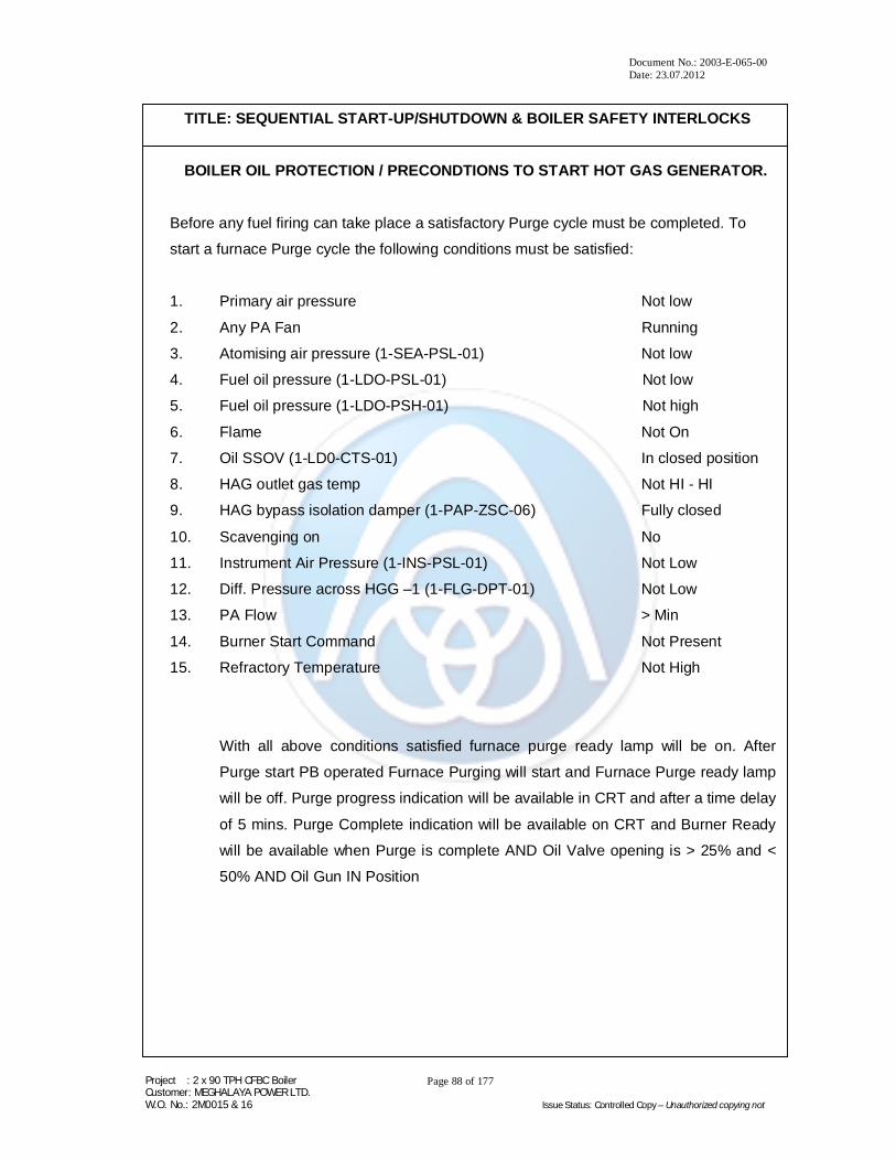
BOILER OIL PROTECTION / PRECONDTIONS TO START HOT GAS GENERATOR.
Before any fuel firing can take place a satisfactory Purge cycle must be completed. To
start a furnace Purge cycle the following conditions must be satisfied:
1. Primary air pressure Not low
2. Any PA Fan Running
3. Atomising air pressure (1-SEA-PSL-01) Not low
4. Fuel oil pressure (1-LDO-PSL-01) Not low
5. Fuel oil pressure (1-LDO-PSH-01) Not high
6. Flame Not On
7. Oil SSOV (1-LD0-CTS-01) In closed position
8. HAG outlet gas temp Not HI - HI
9. HAG bypass isolation damper (1-PAP-ZSC-06) Fully closed
10. Scavenging on No
11. Instrument Air Pressure (1-INS-PSL-01) Not Low
12. Diff. Pressure across HGG –1 (1-FLG-DPT-01) Not Low
13. PA Flow > Min
14. Burner Start Command Not Present
15. Refractory Temperature Not High
With all above conditions satisfied furnace purge ready lamp will be on. After
Purge start PB operated Furnace Purging will start and Furnace Purge ready lamp
will be off. Purge progress indication will be available in CRT and after a time delay
of 5 mins. Purge Complete indication will be available on CRT and Burner Ready
will be available when Purge is complete AND Oil Valve opening is > 25% and <
50% AND Oil Gun IN Position

Document No.: 2003-E-065-00 Date: 23.07.2012
Project : 2 x 90 TPH CFBC Boiler Customer: MEGHALAYA POWER LTD. W.O. No.: 2M0015 & 16 Issue Status: Controlled Copy – Unauthorized copying not
Page 89 of 177
TITLE: SEQUENTIAL START-UP/SHUTDOWN & BOILER SAFETY INTERLOCKS
Start Oil Burner From Local/DCS
Burner Start Command:
With Burner Ready signal On AND Local / Remote mode selected
AND
Burner Start PB Operated OR Burner Start command from CRT
Following Cycle will be initiated:
Step – 1 Ignitor Will Be Inserted And When Ignitor Retract Limit Switch Is Released Ignitor
transformer Will Be energized For 20 secs.
Step – 2
When Ignitor is Inserted, Atomising Air Valve will Open and Oil Valve will Open
simultaneously. Step – 3 – Condition – 1
Ignition Timer Over and Oil Flame established. Oil and Atomising
Valves will remain Open
Condition – 2 Ignition Time Over, Oil valve Opened But Oil Flame Failed to establish.
Oil valve will close. Ignitor will be Inserted and energized. Scavenge On/ Start
Indication will be available on CRT and Atomising Valve will remain in open
condition. Scavenge Valve will Open.
After 20 secs. HEA will be De-energised and after 25 secs. both scavenge and
atomizing valve will close.
Step – 4
Oil Burner firing and burner stop PB Operated
Oil Valve will Close and Atomising Valve will remain Open.
Scavenging On/Start indication will be available on CRT.
Ignitor will be Inserted and energized
Scavenging Valve will Open.
After 20 secs. Ignitor will be De-energised and retracted.
After 25 secs. Both Scavenging and atomising Valves will close.

Document No.: 2003-E-065-00 Date: 23.07.2012
Project : 2 x 90 TPH CFBC Boiler Customer: MEGHALAYA POWER LTD. W.O. No.: 2M0015 & 16 Issue Status: Controlled Copy – Unauthorized copying not
Page 90 of 177
TITLE: SEQUENTIAL START-UP/SHUTDOWN & BOILER SAFETY INTERLOCKS
Step – 5 Oil Burner Firing and HAG Trips due to any one of the following conditions:
Primary Air Pressure Low
Atomising Air Pressure Low.
HAG Outlet temperature High High.
Emergency Stop PB Operated.
Oil pressure low or High
Diff. Pressure across HAG Low
Primary air Flow Low
Then the Following Occurs:
Oil Valve will Close and atomising Valve will close.
No Scavenging will take place.

Document No.: 2003-E-065-00 Date: 23.07.2012
Project : 2 x 90 TPH CFBC Boiler Customer: MEGHALAYA POWER LTD. W.O. No.: 2M0015 & 16 Issue Status: Controlled Copy – Unauthorized copying not
Page 91 of 177
TITLE: SEQUENTIAL START-UP/SHUTDOWN & BOILER SAFETY INTERLOCKS
D. PRECONDITIONS TO START MAIN FUEL
FUEL FEEDER START / STOP SIGNAL
Fuel feeder will start after start command is given from CRT if the following conditions are satisfied:
1. Selection (1-VFD02/03-XS) Remote 2. CF – 1 (1-VFD-02/03-XA) Not running 3. Feeder 1/2 Outlet Date (1-FHS-ZSO-02/04) Open 4. Drive (1-VFD-02/03-XH) Healthy 5. Feeder.(1-VFD-02/03-XT) Not Tripped 6. Bed temp > Min 1A (2 out of 4 logic) 7. Air protection O.K. 8. Boiler Not tripped 9. Any PA fan Running 10. Fuel feeder Stop PB (DCS) Not operated 11. Trip coal feeder signal Not present.
Start one Fuel Feeder from DCS Vary Speed as Required. Start second fuel feeder as required.
Note: Adequate numbers of “Rods” are withdrawn from Rod type gate of Feeder I and / or II prior to check permissive.
Fuel feeder will stop / trip if any one of the following signal is present :
1. PA fan Not running 2. Boiler Tripped 3. Bed temp > 920deg C 4. Fuel feeder –1 Drive(1-VFD-02/03-XT) Fault/Trip 5. Fuel feeder –1 stop PB (DCS) Operated 6. Drive (1-VFD-02/03-XH) Not Healthy 7. CF O/L gate (1-FHS-ZSC-02/04) Closed 8. Bed Temperature < Min 3 9. Siphon 1 / 2 Outlet temperature > Max (450 oC)

Document No.: 2003-E-065-00 Date: 23.07.2012
Project : 2 x 90 TPH CFBC Boiler Customer: MEGHALAYA POWER LTD. W.O. No.: 2M0015 & 16 Issue Status: Controlled Copy – Unauthorized copying not
Page 92 of 177
TITLE: SEQUENTIAL START-UP/SHUTDOWN & BOILER SAFETY INTERLOCKS
D3.3.0.0 TRIPPING SEQUENCE -
A. AIR FLUE TRIPPING SEQUENCE:
Coal tripping sequence OK
PA fan Off / Trip
PA fan suction dampers (control) Close
PA fan discharge dampers Close
SA fan Off / Trip
SA fan Suction (control) damper Close
SA fan discharge damper Close
ID fan Off / Trip
ID fan suction (control) damper Close
ID fan discharge damper Close
Note: All discharge dampers of ID; SA, PA fans may also be closed.

Document No.: 2003-E-065-00 Date: 23.07.2012
Project : 2 x 90 TPH CFBC Boiler Customer: MEGHALAYA POWER LTD. W.O. No.: 2M0015 & 16 Issue Status: Controlled Copy – Unauthorized copying not
Page 93 of 177
TITLE: SEQUENTIAL START-UP/SHUTDOWN & BOILER SAFETY INTERLOCKS
BAMBOO CHIP FEEDER START / STOP Bamboo Chip Feeder will start after start command is given from CRT if the following Input conditions are satisfied:
1. Remote (1-VFD07-XS) Selected 2. Drive (1-VFD07-XH) Healthy
3. Belt Conveyor (1-VFD08-XA) Not Running
4. Bed Temperature (2 Out of 3 Logic) > Min 1A
5. Air Protection OK
6. Boiler Not Tripped
7. BCF (1-VFD07-XA) Not Running
8. PA Fan 1 or 2 Running
9. BCF Stop PB (DCS) Not Operated
10. Drive (1-VFD07-XT) No Fault
11. Trip Signal Not Present
12. Local Stop PB Not Operated
Bamboo Chip Feeder will stop / Trip if any one of the following input signals is present:
1. PA Fans 1 and 2 Not Running 2. Boiler Tripped
3. Bed temperature > 920 Deg C
4. BCF Stop PB (DCS) Operated
5. Drive (1-VFD07-XH) Not healthy
6. Drive (1-VFD07-XT) Fault
7. Bed temperature < Min 3
8. Local Stop PB Operated

Document No.: 2003-E-065-00 Date: 23.07.2012
Project : 2 x 90 TPH CFBC Boiler Customer: MEGHALAYA POWER LTD. W.O. No.: 2M0015 & 16 Issue Status: Controlled Copy – Unauthorized copying not
Page 94 of 177
TITLE: SEQUENTIAL START-UP/SHUTDOWN & BOILER SAFETY INTERLOCKS
D3.4.0.0 SAFE LIMITS/TRIP LEVELS FOR CFBC BOILER
Sl. No.
Description Limits
(Max/Min) Set Value Unit
1. Furnace pressure min. 2
max. 2
(-)150
(+)100 mmWC
2. ID fan I inlet pressure
ID fan II inlet pressure min. 2 (-)510 mmWC
3.
Primary air flow (Total)
Primary air flow to the HGG
min. 2
min. 2
11
5.5
kg/sec
kg/sec
4.
Drum level-I
Drum level- II
Drum level-I
Drum level-II
min. 2
min. 2
max. 2
max. 2
(-)320
(-)320
150
150
mm
5.
Fluidised bed temperature
Fluidised bed temperature
Fluidised bed temperature coal
Fluidised bed temperature
max. 2
max. 3
min. 1A
min. 3
940
920
> Ignition
Temp
350
°C
Note: 1. "Min .2" and "Max. 2" are limiting values of boiler trip.
2. In the event of “Boiler trip", (on account of reaching min 2/max 2 values) "Air/Flue
tripping sequence" should be initiated automatically. This will immensely help to
achieve quick start of boiler when normal condition is restored for restart.
3. Permissive (min.) to start coal firing is indicated a "Min. 1A".
4. Coal feeders (only) should trip if fluidised bed temperature exceeds "Max.
3" or drops below "Min. 3" once coal is charged.
5. Set values mentioned for Bed Temp. (Sl. No. 5 above) are indicative and
shall be adjusted during commissioning.
6. ID Fans shall run for approx. 10 minutes in case of planned trip.
7. CO Vent valve shall be opened after boiler trip as a safety measure.
Document No.: 2003-E-065-00 Date: 23.07.2012
Project : 2 x 90 TPH CFBC Boiler Customer: MEGHALAYA POWER LTD. W.O. No.: 2M0015 & 16 Issue Status: Controlled Copy – Unauthorized copying not
Page 95 of 177
TITLE: SEQUENTIAL START-UP/SHUTDOWN & BOILER SAFETY INTERLOCKS
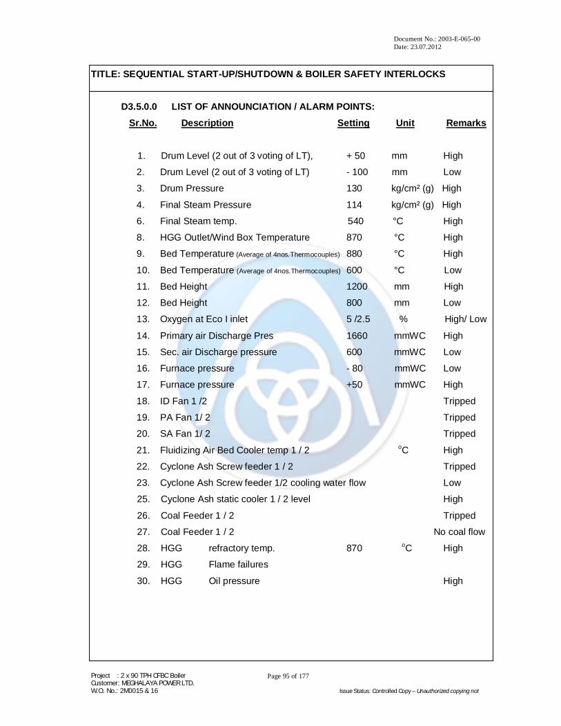
D3.5.0.0 LIST OF ANNOUNCIATION / ALARM POINTS: Sr.No. Description Setting Unit Remarks
1. Drum Level (2 out of 3 voting of LT), + 50 mm High
2. Drum Level (2 out of 3 voting of LT) - 100 mm Low
3. Drum Pressure 130 kg/cm² (g) High
4. Final Steam Pressure 114 kg/cm² (g) High
6. Final Steam temp. 540 °C High
8. HGG Outlet/Wind Box Temperature 870 °C High
9. Bed Temperature (Average of 4nos.Thermocouples) 880 °C High
10. Bed Temperature (Average of 4nos.Thermocouples) 600 °C Low
11. Bed Height 1200 mm High
12. Bed Height 800 mm Low
13. Oxygen at Eco I inlet 5 /2.5 % High/ Low
14. Primary air Discharge Pres 1660 mmWC High
15. Sec. air Discharge pressure 600 mmWC Low
16. Furnace pressure - 80 mmWC Low
17. Furnace pressure +50 mmWC High
18. ID Fan 1 /2 Tripped
19. PA Fan 1/ 2 Tripped
20. SA Fan 1/ 2 Tripped
21. Fluidizing Air Bed Cooler temp 1 / 2 oC High
22. Cyclone Ash Screw feeder 1 / 2 Tripped
23. Cyclone Ash Screw feeder 1/2 cooling water flow Low
25. Cyclone Ash static cooler 1 / 2 level High
26. Coal Feeder 1 / 2 Tripped
27. Coal Feeder 1 / 2 No coal flow 28. HGG refractory temp. 870 oC High
29. HGG Flame failures
30. HGG Oil pressure High
Document No.: 2003-E-065-00 Date: 23.07.2012
Project : 2 x 90 TPH CFBC Boiler Customer: MEGHALAYA POWER LTD. W.O. No.: 2M0015 & 16 Issue Status: Controlled Copy – Unauthorized copying not
Page 96 of 177
TITLE: SEQUENTIAL START-UP/SHUTDOWN & BOILER SAFETY INTERLOCKS
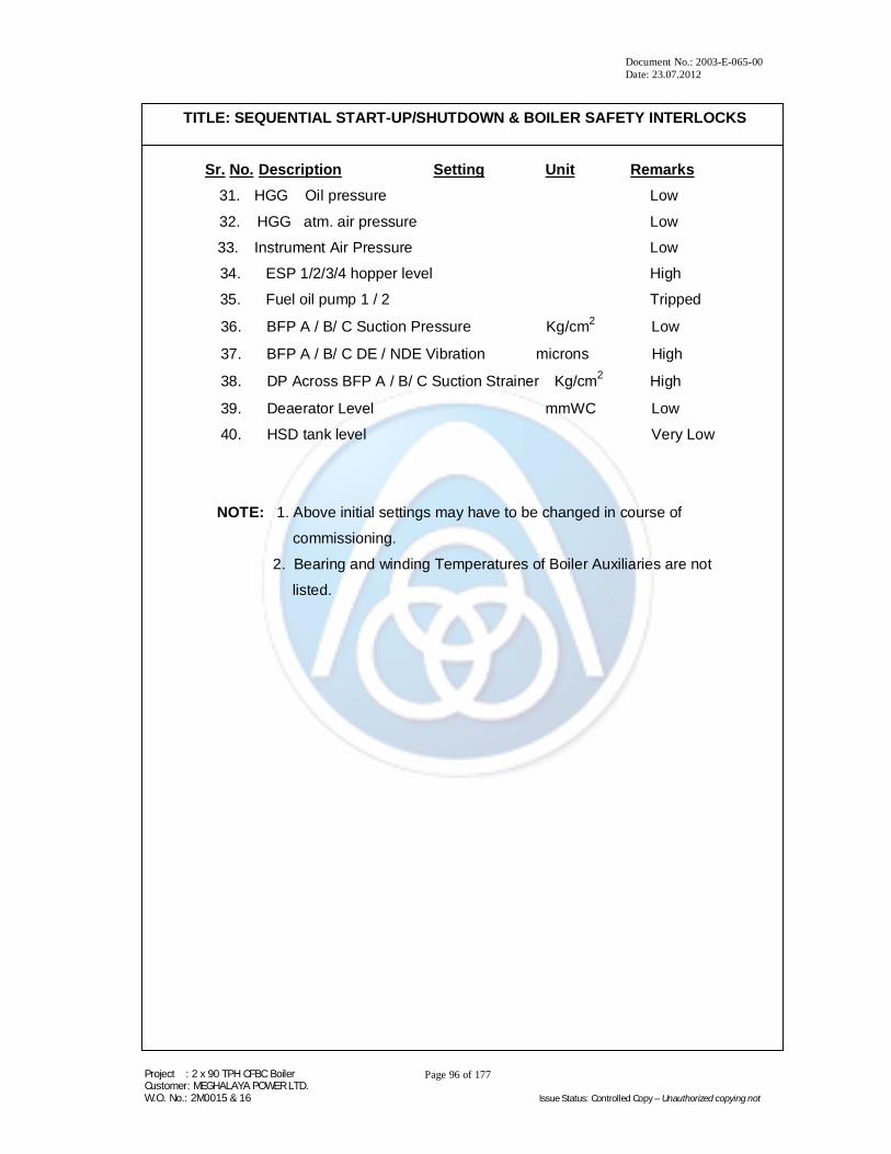
Sr. No. Description Setting Unit Remarks 31. HGG Oil pressure Low
32. HGG atm. air pressure Low
33. Instrument Air Pressure Low
34. ESP 1/2/3/4 hopper level High
35. Fuel oil pump 1 / 2 Tripped
36. BFP A / B/ C Suction Pressure Kg/cm2 Low
37. BFP A / B/ C DE / NDE Vibration microns High
38. DP Across BFP A / B/ C Suction Strainer Kg/cm2 High
39. Deaerator Level mmWC Low
40. HSD tank level Very Low
NOTE: 1. Above initial settings may have to be changed in course of
commissioning.
2. Bearing and winding Temperatures of Boiler Auxiliaries are not
listed.

Document No.: 2003-E-065-00 Date: 23.07.2012
Project : 2 x 90 TPH CFBC Boiler Customer: MEGHALAYA POWER LTD. W.O. No.: 2M0015 & 16 Issue Status: Controlled Copy – Unauthorized copying not
Page 97 of 177
TITLE: SEQUENTIAL START-UP/SHUTDOWN & BOILER SAFETY INTERLOCKS
D3.6.0.0 LIST OF SOE POINTS:
Sr. No. Description Setting Unit Remarks
1. Drum Level (2 out of 3 voting of LT) +150 mm. HI – HI
2. Drum Level (2 out of 3 voting of LT) -320 mm LO – LO
3. Bed Temperature (2 out of 4 voting of TC) 940 °C HI - HI
4. Bed Height 1400 mm HI – HI
5. Bed Height 500 mm LO- LO
6. Primary Disch. Pressure 1750 mmWC High
7. Primary Disch. Pressure 800 mmWC LO-LO
8. Furnace Pressure -150 mmWC LO –LO
9. Furnace pressure +100 mmWC HI – HI
10. ID Fan 1 / 2 Tripped
11. PA Fan 1 / 2 Tripped
12. SA Fan 1 / 2 Tripped
13. Primary air flow <15 Kg/sec Low
14. Secondary air flow <2 Kg/sec Low
15. Tertiary air flow <1 Kg/sec Low
16. ID Fan Brg. (DE / NDE) Temp. 90 Deg C HI-HI
17. PA Fan Brg. (DE / NDE) Temp. 90 Deg C HI-HI
18. SA Fan Brg. (DE / NDE) Temp. 90 Deg C HI-HI
19. ID Fan (DE / NDE) Brg. Vibration 11 mm/sec High
20. PA Fan (DE / NDE) Brg. Vibration 11 mm/sec High
21. SA Fan (DE / NDE) Brg. Vibration 11 mm/sec High
22. Final Steam Temperature 480 Deg C LO-LO
23. ID Fan Suction Pressure -550 mmWC LO-LO
NOTE: 1. Above initial settings may have to be changed in course of
commissioning.

Document No.: 2003-E-065-00 Date: 23.07.2012
Project : 2 x 90 TPH CFBC Boiler Customer: MEGHALAYA POWER LTD. W.O. No.: 2M0015 & 16 Issue Status: Controlled Copy – Unauthorized copying not
Page 98 of 177
TITLE: HOT GAS GENERATOR - OPERATION
D4 - 0 - 0 - 0 HOT GAS GENERATOR - OPERATION

Document No.: 2003-E-065-00 Date: 23.07.2012
Project : 2 x 90 TPH CFBC Boiler Customer: MEGHALAYA POWER LTD. W.O. No.: 2M0015 & 16 Issue Status: Controlled Copy – Unauthorized copying not
Page 99 of 177
TITLE: HOT GAS GENERATOR - OPERATION
D4.1.0.0 PURPOSE OF HOT GAS GENERATOR (HGG)
In CFBC Boiler, usually coal or lignite is the main fuel for normal operation. It is
therefore necessary that the injected fuel falls in the surrounding which is conducive to
start its burning and is sustained. PF boilers have "Light-up" oil burners, likewise in
CFBC boiler, we have to raise the temperature of bed material, before charging main
fuel to a level which is, say 20°C above the ignition temperature of fuel.
The HGG is mounted on cradle and suspended from Constant Load Hangers. HGG
outlet is fixed to the Airbox for initial heating of the bed material. The HGG is fed by
combustion air, i.e. primary air and dilution air from PA Fans. A set of dampers
regulates the air quantity suitably. Hot gas generators gradually raise the bed
temperature at a predetermined rate up to ignition temperature of the main fuel (coal).
D4.2.0.0 OPERATION OF HGG
Under "cold start" condition, Fans are started in the sequence ID, SA, PA. Furnace
draft is maintained at about (-) 30 mmWC keeping primary airflow just above fluidisation
level. Pre-requisites for starting HGG are:
1. Oil pressure at burner gun 6 Kg/cm2 (g) minimum
2. Compressed air for atomisation 7 Kg/cm2 (g) minimum
3. Differential across the HGG 25 mmWC minimum
4. Total primary air flow 17 Kg/sec minimum
One (1) Local Push Button Stations (LPBS), with various digital indicators, lamps & etc.,
are provided for the operation of the HGG, respectively. The burner management logic
and safety interlocks are built in the main DCS.

Document No.: 2003-E-065-00 Date: 23.07.2012
Project : 2 x 90 TPH CFBC Boiler Customer: MEGHALAYA POWER LTD. W.O. No.: 2M0015 & 16 Issue Status: Controlled Copy – Unauthorized copying not
Page 100 of 177
TITLE: HOT GAS GENERATOR - OPERATION
Press burner "start" push button. Sequential operation will start, the HEA Ignitor
will insert & spark will start, which will initiate to open oil "shut off valve" and
atomizing air valve.
As the Oil starts flowing, the Main burner is lighted up keeping oil flow around 150 kg/hr.
The sparking of igniter will stop after 15secs. In case the Oil does not catch fire during
this period the whole sequence is to start again.
The combustion air damper is to be adjusted to the predetermined “air-fuel oil ratio” for
efficient combustion and to keep the flame healthy. Keep the dilution air quantity
sufficient to maintain HGG outlet gas temperature at around 350 OC initially. Gradually,
start raising the oil flow till it reaches around 900 kg/hr. Open dilution air damper such
that HGG outlet gas temperature rises gradually and does not exceed 850 OC in any
case. This is important to have uniform thermal expansion of refractory bricks of HGG.
Main fuel (coal) is charged after temperature of bed material exceeds ignition
temperature of the fuel and all other boiler interlocks are fulfilled. Due to cold fuel,
initially there is slight "dip" in bed temperature. However, it picks up soon and after the
bed temperature exceeds 700°C, gradually reduce the oil flow to about 250 kg/hr and
then smoothly trip the HGG.
The entire HGG operation can also be done in “Auto” mode from LPBS, where fuel flow
rate, airflow are regulated at predetermined ratio and also the HGG outlet temp. is
controlled at preset gradient. For further specific operational details of HGG, please
refer HGG supplier’s “Operation & Maintenance Manual”.

Document No.: 2003-E-065-00 Date: 23.07.2012
Project : 2 x 90 TPH CFBC Boiler Customer: MEGHALAYA POWER LTD. W.O. No.: 2M0015 & 16 Issue Status: Controlled Copy – Unauthorized copying not
Page 101 of 177
TITLE: HOT GAS GENERATOR - OPERATION
D4.3.0.0 HGG – PROTECTION & SAFETY
Control circuit incorporates the operation logic & safety interlocks such as low fuel oil
pressure, low atomising air pressure; differential pressure across the HGG drops below
safe values, HGG gas outlet temperature exceeds safe operating limits, no-flame signal
from flame scanner etc. HGG must be tripped in the event of occurrence of one of the
above conditions. In the event of such tripping, the whole cycle from clearing the
precondition has to be repeated.

Document No.: 2003-E-065-00 Date: 23.07.2012
Project : 2 x 90 TPH CFBC Boiler Customer: MEGHALAYA POWER LTD. W.O. No.: 2M0015 & 16 Issue Status: Controlled Copy – Unauthorized copying not
Page 102 of 177
TITLE: COLD START-UP OF BOILER
D5 - 0 - 0 - 0 COLD START-UP OF BOILER

Document No.: 2003-E-065-00 Date: 23.07.2012
Project : 2 x 90 TPH CFBC Boiler Customer: MEGHALAYA POWER LTD. W.O. No.: 2M0015 & 16 Issue Status: Controlled Copy – Unauthorized copying not
Page 103 of 177
TITLE: COLD START-UP OF BOILER
D5.0.0.0 COLD START-UP OF BOILER
During cold start-up of boiler, Hot Gas Generator (HGG) must be fired at minimum firing
rate i.e. about 150 kg/hr fuel oil flow. Also, HGG must be operated with high dilution air
in order to keep the HGG outlet temperatures low. Initially, Superheater drain valves
are kept open, along with drum and Superheater vent valves. When drum pressure
exceeds 2 kg/cm², drum vent valve and Superheater vent valves should be closed.
Once drum pressure reaches approx. 5 kg/cm², Superheater drain valves are kept
partially open for allowing steam flow through the Superheaters.
Adjust fuel oil flow rate, dilution air such that hot gas generator outlet temperature does
not exceed 600º C above the saturated steam temperature. At approximately 15 kg/cm²
drum pressure, close all S/H drains and partially open start up vent valves such that
drum pressure increase is kept within permissible gradient 2 kg/cm² (g) per minute. This
will allow steam flow through the super-heaters and final steam temperature will also
increase as per requirement. Overheating of superheater’s must be avoided.
After fluidised bed temperature reaches about 20 OC above the ignition temperature of
main fuel (coal), charge the main fuel slowly through first stream. Initially, main fuel
feed should be minimum, say 10% of MCR requirement. There may be slight dip in
fluidised bed temperature initially, but in a few minutes the temperature will start
increasing. Gradually reduce oil flow of HGG as fuel firing stabilises. Slowly start the
second stream of main fuel. Once the fuel firing through both the streams is
established, HGG should be switched off gradually. The HGG Bypass damper should
also be opened gradually.
Increase in steam pressure and corresponding increase in steam temperature is
controlled by regulating the start-up vent valve but within permissible gradient i.e. 2
kg/cm2 per minute.
Initially, primary air is admitted through the Airpreheater bypass duct to minimise the
cold end corrosion of Airpreheater. Once the flue gas temperature at Airpreheater outlet
reaches approximately 130º C, Airpreheater is brought in to the service for heating PA &
SA and gradually airflow through Airpreheater by-pass duct is closed.
SEE "PRESSURE RAISING" & CHARGING MAIN FUEL" CHAPTERS ALSO.

Document No.: 2003-E-065-00 Date: 23.07.2012
Project : 2 x 90 TPH CFBC Boiler Customer: MEGHALAYA POWER LTD. W.O. No.: 2M0015 & 16 Issue Status: Controlled Copy – Unauthorized copying not
Page 104 of 177
TITLE: HOT START-UP OF BOILER
D6 - 0 - 0 - 0 HOT START-UP OF BOILER

Document No.: 2003-E-065-00 Date: 23.07.2012
Project : 2 x 90 TPH CFBC Boiler Customer: MEGHALAYA POWER LTD. W.O. No.: 2M0015 & 16 Issue Status: Controlled Copy – Unauthorized copying not
Page 105 of 177
TITLE: HOT START-UP OF BOILER
D6.0.0.0 HOT START-UP OF BOILER
Boiler can be started without starting the HGG if the fluidised bed temperature is at least
20ºC above ignition temperature of the main fuel. This is possible after a short duration
shut down of boiler. Main fuel (coal) can be charged directly after all auxiliary fans have
started and bed fluidisation is maintained by ensuring minimum primary air flow.
Starting procedure and preconditions for boiler start-up shall be as explained in the
chapter “SEQUENTIAL START-UP/SHUTDOWN & BOILER SAFETY INTERLOCKS”
(CHAPTER D3-0-0-0).
Start coal feeding with minimum fuel flow (say 10% of MCR requirement) through one
stream. There may be slight dip in temperature of bed initially, but in a few minutes, bed
temperature will start increasing. Start now second stream of coal feed and allow it to
stabilise.
Increase in steam pressure and corresponding increase in steam temperature is
controlled by regulating the start-up vent valve but within permissible gradient i.e. 2
kg/cm2 per minute.
It should be noted that during hot start-up, bed material is likely to get cooled-down
rapidly when minimum primary airflow is established. Therefore, it is advisable to start
charging of fuel quickly while the bed temperature is sufficiently high.

Document No.: 2003-E-065-00 Date: 23.07.2012
Project : 2 x 90 TPH CFBC Boiler Customer: MEGHALAYA POWER LTD. W.O. No.: 2M0015 & 16 Issue Status: Controlled Copy – Unauthorized copying not
Page 106 of 177
TITLE: PRESSURE RISING OF BOILER
D7 - 0 - 0 - 0 PRESSURE RAISING OF BOILER

Document No.: 2003-E-065-00 Date: 23.07.2012
Project : 2 x 90 TPH CFBC Boiler Customer: MEGHALAYA POWER LTD. W.O. No.: 2M0015 & 16 Issue Status: Controlled Copy – Unauthorized copying not
Page 107 of 177
TITLE: PRESSURE RISING OF BOILER
D7.0.0.0 PRESSURE RAISING OF BOILER
Boiler circulation should start soon after a fire is lit in combustor. Top headers and drum
should become warmer first followed by lower portion.
Close the steam drum vent when drum pressure is 2 kg/cm²g. Superheater vents may
also be closed. Close Superheater inlet header drains at pressure 5 kg/cm²g and open
the start up vent until the unit is put on load. Opening of start up vent should be
controlled to help raise the pressure in boiler and at the same time the super-heaters
are properly cooled.
It is advisable to warm up the boiler by continuous firing to maintain the continuous
water/steam circulation thus assuring uniform heating of the boiler and minimum of
stresses to the pressure parts and refractory.
In cases where the steam pressure is raised with intermittent firing, it is possible to
arrive at full operating pressure in steam drum and still have lower portion of furnace
relatively cool.
During pressure raising the water level will normally rise to the top of gauge glasses as
steam pressure is increased. This is due to expansion in volume of water due to heat
transfer and circulation. The excess water from system should be removed by blow
down. Especially, lower water wall blow-off may be advantageous, as this will
accelerate circulation.
While giving the blow-down, do not keep the blow-down valves open for more than 20
seconds. The blow-down normally should be given with quick open/close operation.
Pressure and load limits of blow off valves operation are:
Up to 60 kg/cm²g 100% load
60 to 85 kg/cm²g 75% load
85 to 100 kg/cm²g 50% load
100 kg/cm²g and above Never
NEVER DRAIN THE BOILER WHEN THERE IS GLOWING SLAG OR ASH IN THE
COMBUSTOR OR FLUE GAS PASSES.

Document No.: 2003-E-065-00 Date: 23.07.2012
Project : 2 x 90 TPH CFBC Boiler Customer: MEGHALAYA POWER LTD. W.O. No.: 2M0015 & 16 Issue Status: Controlled Copy – Unauthorized copying not
Page 108 of 177
TITLE: CHARGING MAIN FUEL
D8 - 0 - 0 - 0 CHARGING MAIN FUEL

Document No.: 2003-E-065-00 Date: 23.07.2012
Project : 2 x 90 TPH CFBC Boiler Customer: MEGHALAYA POWER LTD. W.O. No.: 2M0015 & 16 Issue Status: Controlled Copy – Unauthorized copying not
Page 109 of 177
TITLE: CHARGING MAIN FUEL
D8.0.0.0 CHARGING MAIN FUEL
During start-up of boiler, as bed temperature approaches the near to the ignition
temperature of main fuel; preparation to start fuel firing has to be completed to enable
main fuel combustion quickly and reduce expensive oil burning.
The sequences of operations are briefly:
1) Open plate type cut off gates above feeders
2) Open rod type cut off gates above coal feeder
3) Open fuel valves/dampers above siphons
4) Start fuel conveyors (where applicable) at min. speed.
Once minimum bed temperature interlock is cleared, start the fuel feeder at lowest
speed. Initial charge of fuel may cause slight fall in bed temperature but soon bed
temperature starts rising and the coal feed also needs to be increased gradually. Bed
temperature, boiler pressure will now rise fairly fast and as Super-heater pressure
reaches the nominal (rated) value the main steam stop valve is opened to put the boiler
on load after warming up of MS line through by-pass valve.
As the bed temperature crosses 700 º C level, gradually reduce oil flow through HGG
and simultaneously increase main fuel flow to maintain rising trend of bed temperature.
Finally, switch off HGG. Although the oil flow is reduced through HGG, total primary
airflow (combustion air plus dilution air) should not be reduced. In other words dilution
air should be increased to compensate decrease in combustion air linked to fuel oil
quantity. Immediately after HGG switch off, open HGG by-pass damper full. HGG
Bypass Dampers maybe controlled to maintain equal airflow through both HGG’s /
maintaining equal O2 % on both LHS & RHS of Flue Gas, if required.
Once the Boiler stabilizes on Coal, 20% Bamboo Chips, maybe fired by operating the
BCF. Necessary precaution maybe taken while firing bamboo chips by monitoring the
Flue Gas Temperature, to ensure complete ignition of Bamboo chips before exiting the
Furnace.

Document No.: 2003-E-065-00 Date: 23.07.2012
Project : 2 x 90 TPH CFBC Boiler Customer: MEGHALAYA POWER LTD. W.O. No.: 2M0015 & 16 Issue Status: Controlled Copy – Unauthorized copying not
Page 110 of 177
TITLE: CHARGING MAIN FUEL
Bed temperature, especially in low load operation, needs to be controlled by regulating
P.A. /S.A. (In practice it is higher than normal requirement). At higher loads, bed
temperature can be stabilised by operating the cyclone ash screw coolers.

Document No.: 2003-E-065-00 Date: 23.07.2012
Project : 2 x 90 TPH CFBC Boiler Customer: MEGHALAYA POWER LTD. W.O. No.: 2M0015 & 16 Issue Status: Controlled Copy – Unauthorized copying not
Page 111 of 177
TITLE: STANDARD OPERATION AND LOAD VARIATION
D9 - 0 - 0 - 0 STANDARD OPERATION AND LOAD VARIATION
Document No.: 2003-E-065-00 Date: 23.07.2012
Project : 2 x 90 TPH CFBC Boiler Customer: MEGHALAYA POWER LTD. W.O. No.: 2M0015 & 16 Issue Status: Controlled Copy – Unauthorized copying not
Page 112 of 177
TITLE: STANDARD OPERATION AND LOAD VARIATION
D9.0.0.0 STANDARD OPERATION AND LOAD VARIATION
As the main fuel firing stabilises, the boiler pressure also gradually rises close to
nominal main steam pressure. First, open by-pass valve of main steam stop valve.
Allow steam to flow for sufficient time to warm up main steam piping. Then open main
steam stop valve and subsequently close by-pass valve.
At this time generally status is:
1) Hot gas generator is switched off.
2) Fuel conveyors and feeders are in service.
3) Bed temperature is at approximately desired level (for coal around
860ºC)
Steam generation from the boiler can be increased or decreased smoothly by regulating
the following:
1) Fuel feed and combustion air
2) Drum level
3) Furnace draft
4) Fluidised bed temperature
5) Steam temperature (especially beyond say 70% of MCR)
D9.1.0.0 FUEL FEED AND COMBUSTION AIR
Normally fuel quantity in bed at any point of time is approximately 3 to 4% of ash
quantity.
Increase in steam supply should promptly increase combustion air (primary and
secondary/tertiary) and the increase in fuel quantity has to follow quickly. Drop in steam
supply should cut down the combustion air promptly and fuel cut has to follow promptly.
Operative behaviour of fuel and combustion air is shown in different diagrams referring
to temperature, pressure and mass flows. Adjusted values of primary, secondary and
tertiary air are maintained by operating personnel or automatic control circuits. The
values of fuel and air will also depend on the fuel characteristics and hence manual
intervention at times becomes necessary in control process.

Document No.: 2003-E-065-00 Date: 23.07.2012
Project : 2 x 90 TPH CFBC Boiler Customer: MEGHALAYA POWER LTD. W.O. No.: 2M0015 & 16 Issue Status: Controlled Copy – Unauthorized copying not
Page 113 of 177
TITLE: STANDARD OPERATION AND LOAD VARIATION
D9.2.0.0 DRUM LEVEL
Usually three element control, i.e. steam flow, feed flow and drum level, is responsible
to regulate feed water flow and maintain water level in drum reasonably steady.
Occasionally, pressure and temperature corrections are also applied in control circuits.
D9.3.0.0 FURNACE DRAFT
Furnace draft of approximately (-) 30 to (-) 50 mmWC is maintained by regulating ID
Fan speed through VFD, either on manual remote mode or auto mode.
D9.4.0.0 FLUIDISED BED TEMPERATURE
Regulating the bed temperature of CFBC boiler can judiciously control emission of
pollutants, such as CO, NOx. Similarly, where desulphurisation of fuel (like lignite) is
desired by dosing limestone, the reaction takes place in fluidised bed. And the
effectiveness of reaction will depend on bed temperature.
Bed temperature with coal as a fuel should be between 840ºC to 880ºC. The
temperature of circulating ash drops to roughly 400º C during its vertically upward travel
as it enters cyclones. The circulating ash is separated in cyclone by centrifugal action
and it is returned to furnace via siphon. Increase or decrease of the quantity of cyclone
ash (at 400ºC) returned to bed (at approx. 850º C) will correspondingly decrease or
increase the bed temperature from its present level.
At siphon, the branch off for extracting the ash is provided which connects to cyclone
ash screw inlet. The speed regulation of cyclone ash screw cooler governs the bed
temperature.
Coal is charged only after bed temperature rises 20°C beyond fuel ignition temperature.
Boiler is tripped in the event of bed temperature shooting up beyond 940ºC.
Coal feeders/BC feeders may be tripped if bed temperature exceeds 920ºC.

Document No.: 2003-E-065-00 Date: 23.07.2012
Project : 2 x 90 TPH CFBC Boiler Customer: MEGHALAYA POWER LTD. W.O. No.: 2M0015 & 16 Issue Status: Controlled Copy – Unauthorized copying not
Page 114 of 177
TITLE: STANDARD OPERATION AND LOAD VARIATION D9.5.0.0 STEAM TEMPERATURE CONTROL
At higher load, say above 70% of MCR, mass flow of flue gas and heat absorption in
the Superheaters reach a stage where it is possible not only to achieve final rated
temperature, but it becomes necessary to cool the steam in stages to maintain final
temperature within close limits.
Stage-I Attemperator is interposed between Superheater-I & Superheater-II such that
Superheater-I outlet steam is cooled by the spray of water and enter Superheater-II at a
desired temperature. Stage-II Attemperator is interposed between Superheater-II and
Superheater-III such that steam entering the Superheater-III is cooled by the spray
water and the final steam outlet temperature is controlled to the desired value.
As the load increases, the quantity of water spray also increases. In the event of only
one spray nozzle, it is likely that at higher water flow, atomization of water may not be
proper, which may adversely effect on life of Attemperator. However, multi-spray nozzle
system incorporated in CFBC boiler ensures fine spray of water, within specific limits
through each nozzle, to achieve quick evaporation.

Document No.: 2003-E-065-00 Date: 23.07.2012
Project : 2 x 90 TPH CFBC Boiler Customer: MEGHALAYA POWER LTD. W.O. No.: 2M0015 & 16 Issue Status: Controlled Copy – Unauthorized copying not
Page 115 of 177
TITLE: ANTICIPATED PERFORMANCE CHARACTERISTICS
D10 - 0 - 0 - 0 ANTICIPATED PERFORMANCE CHARACTERISTICS

Document No.: 2003-E-065-00 Date: 23.07.2012
Project : 2 x 90 TPH CFBC Boiler Customer: MEGHALAYA POWER LTD. W.O. No.: 2M0015 & 16 Issue Status: Controlled Copy – Unauthorized copying not
Page 116 of 177
TITLE: ANTICIPATED PERFORMANCE CHARACTERISTICS
D10.0.0.0 ANTICIPATED PERFORMANCE CHARACTERISTICS
1. Boiler Load % Vs Steam Flow (TPH).
2. Air Staging (kg/s) for Coal Grade – F.
3. Air Staging (%) for performance coal.
4. Boiler Load Vs Attemperator Spray flow.
5. Boiler Load % Vs Excess air coefficient
6. Boiler Load % Vs Fuel consumption.
7. Excess Air Vs Excess Oxygen in flue gas.
8. Boiler Load Vs Flue gas Temperature profile.
9. Coal Feeder Speed Vs Coal Flow.
10. Boiler Load Vs Water & Steam Temperature profile.

Document No.: 2003-E-065-00 Date: 23.07.2012
Project : 2 x 90 TPH CFBC Boiler Customer: MEGHALAYA POWER LTD. W.O. No.: 2M0015 & 16 Issue Status: Controlled Copy – Unauthorized copying not
Page 117 of 177
TITLE: ANTICIPATED PERFORMANCE CHARACTERISTICS
Boiler Load
0
5
10
15
20
25
30
35
40
45
50
55
60
65
70
75
80
85
90
95
100
0 10 20 30 40 50 60 70 80 90 100 110
Boiler Load (%)
Boi
ler L
oad
(TPH
)

Document No.: 2003-E-065-00 Date: 23.07.2012
Project : 2 x 90 TPH CFBC Boiler Customer: MEGHALAYA POWER LTD. W.O. No.: 2M0015 & 16 Issue Status: Controlled Copy – Unauthorized copying not
Page 118 of 177
TITLE: ANTICIPATED PERFORMANCE CHARACTERISTICS
Air Staging (Kg/s)Fuel: Meghalaya Coal
Total Air
Primary Air
Secondary Air
Tertiary Air
0
5
10
15
20
25
30
0 10 20 30 40 50 60 70 80 90 100Boiler Load %
Air
Stag
ing
(Kg/
s)
Document No.: 2003-E-065-00 Date: 23.07.2012
Project : 2 x 90 TPH CFBC Boiler Customer: MEGHALAYA POWER LTD. W.O. No.: 2M0015 & 16 Issue Status: Controlled Copy – Unauthorized copying not
Page 119 of 177
TITLE: ANTICIPATED PERFORMANCE CHARACTERISTICS
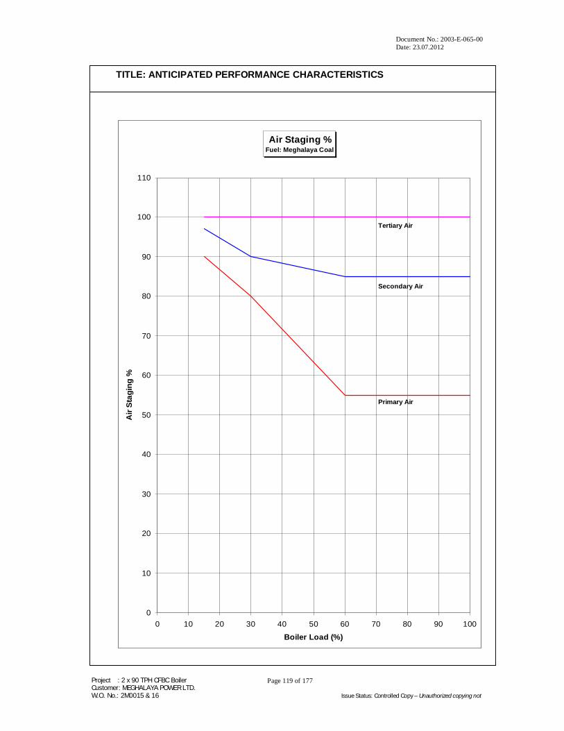
Air Staging %Fuel: Meghalaya Coal
0
10
20
30
40
50
60
70
80
90
100
110
0 10 20 30 40 50 60 70 80 90 100
Boiler Load (%)
Air
Stag
ing
%
Tertiary Air
Secondary Air
Primary Air

Document No.: 2003-E-065-00 Date: 23.07.2012
Project : 2 x 90 TPH CFBC Boiler Customer: MEGHALAYA POWER LTD. W.O. No.: 2M0015 & 16 Issue Status: Controlled Copy – Unauthorized copying not
Page 120 of 177
TITLE: ANTICIPATED PERFORMANCE CHARACTERISTICS
Anticipated Attemperator Spray Water FlowSpray Water Temperature: 230 Deg C
Fuel: Meghalaya Coal
Attemperator # 1
Attemperator # 2
0.00
0.50
1.00
1.50
2.00
2.50
3.00
3.50
4.00
60 65 70 75 80 85 90 95 100 105
Boiler Load (%)
Spra
y W
ater
(TPH
)

Document No.: 2003-E-065-00 Date: 23.07.2012
Project : 2 x 90 TPH CFBC Boiler Customer: MEGHALAYA POWER LTD. W.O. No.: 2M0015 & 16 Issue Status: Controlled Copy – Unauthorized copying not
Page 121 of 177
TITLE: ANTICIPATED PERFORMANCE CHARACTERISTICS
Excess Air Co-efficientFuel: Meghalaya Coal
1.00
1.10
1.20
1.30
1.40
1.50
1.60
1.70
1.80
1.90
2.00
2.10
2.20
2.30
2.40
2.50
0 10 20 30 40 50 60 70 80 90 100 110
Boiler Load %
Exce
ss A
ir C
o-ef
feci
ent

Document No.: 2003-E-065-00 Date: 23.07.2012
Project : 2 x 90 TPH CFBC Boiler Customer: MEGHALAYA POWER LTD. W.O. No.: 2M0015 & 16 Issue Status: Controlled Copy – Unauthorized copying not
Page 122 of 177
TITLE: ANTICIPATED PERFORMANCE CHARACTERISTICS
Anticipated Fuel Consumption (TPH)Fuels: Performance Coal (GCV - 5520 kCal/kg)
Design Coal (GCV- 3345 kCal/kg)
0
1
2
3
4
5
6
7
8
9
10
11
12
13
14
15
16
17
18
19
20
0 10 20 30 40 50 60 70 80 90 100 110
Boiler Load (%)
Fuel
Con
sum
ptio
n (T
PH)
DESIGN FUEL
PERFORMANCE FUEL

Document No.: 2003-E-065-00 Date: 23.07.2012
Project : 2 x 90 TPH CFBC Boiler Customer: MEGHALAYA POWER LTD. W.O. No.: 2M0015 & 16 Issue Status: Controlled Copy – Unauthorized copying not
Page 123 of 177
TITLE: ANTICIPATED PERFORMANCE CHARACTERISTICS
2.0
2.2
2.4
2.6
2.8
3.0
3.2
3.4
3.6
3.8
4.0
4.2
4.4
4.6
4.8
5.0
5.2
5.4
5.6
15 20 25 30 35 40 45
Excess Air %
O2
% W
et (
% b
y V
olum
e)
EXCESS AIR Vs EXCESS OXYGENPerformance Fuel: Indian Coal

Document No.: 2003-E-065-00 Date: 23.07.2012
Project : 2 x 90 TPH CFBC Boiler Customer: MEGHALAYA POWER LTD. W.O. No.: 2M0015 & 16 Issue Status: Controlled Copy – Unauthorized copying not
Page 124 of 177
TITLE: ANTICIPATED PERFORMANCE CHARACTERISTICS
Anticipated Flue Gas Temperature ProfilePerformance Fuel: Meghalaya Coal
Screen Inlet
SH3 Inlet
SH2 Inlet
SH1 Inlet
Evaporator Inlet
ECO2 Inlet
Cyclone Inlet
AH Inlet
AH Outlet
Bed Temperature
0.00
50.00
100.00
150.00
200.00
250.00
300.00
350.00
400.00
450.00
500.00
550.00
600.00
650.00
700.00
750.00
800.00
850.00
900.00
950.00
60 65 70 75 80 85 90 95 100
Boiler Load (%)
Flue
Gas
Tem
pera
ture
(Deg
. C)

Document No.: 2003-E-065-00 Date: 23.07.2012
Project : 2 x 90 TPH CFBC Boiler Customer: MEGHALAYA POWER LTD. W.O. No.: 2M0015 & 16 Issue Status: Controlled Copy – Unauthorized copying not
Page 125 of 177
TITLE: ANTICIPATED PERFORMANCE CHARACTERISTICS
Fuel Feeder Speed Vs Fuel Feeder FlowFeeder Width = 550 mm ; Bed Height = 180 mm / 80 mm ; Fuel Density = 800 Kg/m3 ; Sprocket PCD = 456.9 mm
Bed Height = 180 mm
Bed Height = 80 mm
0
5
10
15
20
25
30
35
40
45
150 200 250 300 350 400 450 500 550 600 650 700 750
Flow (TPH)
Motor Speed = 750 RPM; Primary Reduction = 40:1 ; Secondary Reduction = 13:38Fuel Flow (TPH) = (Bed Width) m x (Bed Height) m x (Fuel Density) T/m3 x 3.142 x (Sprocket PCD) m x (Feeder RPM) x 60
Mot
or S
peed
(RPM
)

Document No.: 2003-E-065-00 Date: 23.07.2012
Project : 2 x 90 TPH CFBC Boiler Customer: MEGHALAYA POWER LTD. W.O. No.: 2M0015 & 16 Issue Status: Controlled Copy – Unauthorized copying not
Page 126 of 177
TITLE: ANTICIPATED PERFORMANCE CHARACTERISTICS
Anticipated Steam & Water Temperature ProfileFuel: Meghalaya Coal
ECO1 In
ECO2 In
ECO2 Out
SH1 In
SH1 Out
SH2 In
SH2 Out
SH3 In
SH3 Out
0
50
100
150
200
250
300
350
400
450
500
550
600
60 65 70 75 80 85 90 95 100
Boiler Load (%)
Tem
pera
ture
(Deg
C)

Document No.: 2003-E-065-00 Date: 23.07.2012
Project : 2 x 90 TPH CFBC Boiler Customer: MEGHALAYA POWER LTD. W.O. No.: 2M0015 & 16 Issue Status: Controlled Copy – Unauthorized copying not
Page 127 of 177
TITLE: NORMAL/STANDARD SHUT DOWN
D11 - 0 - 0 - 0 NORMAL/STANDARD SHUT-DOWN

Document No.: 2003-E-065-00 Date: 23.07.2012
Project : 2 x 90 TPH CFBC Boiler Customer: MEGHALAYA POWER LTD. W.O. No.: 2M0015 & 16 Issue Status: Controlled Copy – Unauthorized copying not
Page 128 of 177
TITLE: NORMAL/STANDARD SHUT DOWN
D11.1.0.0 NORMAL/STANDARD SHUT DOWN
In principle, the firing can be switched off at any boiler load without a special
preparation. Usually, generation of steam is gradually reduced to minimum load and
then shut down is initiated to bank the steam generator. Refer “SEQUENTIAL START-
UP/SHUTDOWN & BOILER SAFETY INTERLOCKS” (CHAPTER D3-0-0-0). While
pulling out the boiler from service sudden pressure and temperature drops must be
avoided so that pressure parts and non-pressure parts of boiler are spared from thermal
shocks.
D11.2.0.0 BOILER BANKING
Recommended sequence of activities for scheduled short shut down of the boiler is as
under:
1. Reduce fuel feed and steam supply to minimum load
2. Switch off coal feeders
3. "Close" the slide gate damper at coal feeder outlet
4. Switch off PA, SA, ID fans
5. Close the main steam stop valve
6. Raise water level to approximately (+)140 mm in gauge glass
7. Switch off feed water pumps.
D11.3.0.0 BOILER SHUT DOWN FOR LONGER OUTAGES
Follow all steps under "BOILER BANKING" and subsequently:
1. Maintain drum level within (-)200 to (+)140, if necessary, by topping up water
through low feed line. Feed pumps may have to be started for short duration.
2. When the drum pressure comes down up to 2 kg/cm2(g) open "Drum &
Superheater Vent" valves.
3. Natural cooling may be adopted for all boiler surfaces.

Document No.: 2003-E-065-00 Date: 23.07.2012
Project : 2 x 90 TPH CFBC Boiler Customer: MEGHALAYA POWER LTD. W.O. No.: 2M0015 & 16 Issue Status: Controlled Copy – Unauthorized copying not
Page 129 of 177
TITLE: NORMAL/STANDARD SHUT DOWN
D11.4.0.0 BOILER SHUT DOWN FOR PRESSURE PARTS REPAIR WORK BY DRAINING
Follow all steps under "BOILER BANKING" and subsequently:
1. Slowly reduce the drum pressure (according to permissible gradients) by regulating
start up vent valve.
2. Open drum & Superheater vents for residual evaporation at 2 kg/cm2 (g) pressure.
3. Start fans and gradually cool furnace and boiler second pass till gas temperature at
inlet of cyclone reaches around 90° C.
4. Switch off the boiler feed pumps.
5. Initiate draining of the boiler from drum pressure 5 kg/cm2 (g).
6. Switch off the fans.

Document No.: 2003-E-065-00 Date: 23.07.2012
Project : 2 x 90 TPH CFBC Boiler Customer: MEGHALAYA POWER LTD. W.O. No.: 2M0015 & 16 Issue Status: Controlled Copy – Unauthorized copying not
Page 130 of 177
TITLE: EMERGENCY SHUT DOWN
D12 - 0 - 0 - 0 EMERGENCY SHUT-DOWN

Document No.: 2003-E-065-00 Date: 23.07.2012
Project : 2 x 90 TPH CFBC Boiler Customer: MEGHALAYA POWER LTD. W.O. No.: 2M0015 & 16 Issue Status: Controlled Copy – Unauthorized copying not
Page 131 of 177
TITLE: EMERGENCY SHUT DOWN
D12.0.0.0 EMERGENCY SHUT DOWN
Boiler could be tripped on account of exceeding safe limits (Min.2 / Max.2 values of
boiler protection) during operation or manually by pressing of the "Emergency Trip”
push button.
Should the pressure starts increasing, open "Start-up Vent" valve partially and reduce
the pressure slightly, say 4 to 5 kg/cm2. Let the boiler cool naturally or initiate forced
cooling, if required (only in emergency), and open drum and super-heater vents when
pressure falls to around 2 to 3 kg/cm2 (g).
Maintain the water level in drum between (+) 140 to (-)150 mmWC.
Now follow the steps under "BOILER BANKING" wherever necessary.
Document No.: 2003-E-065-00 Date: 23.07.2012
Project : 2 x 90 TPH CFBC Boiler Customer: MEGHALAYA POWER LTD. W.O. No.: 2M0015 & 16 Issue Status: Controlled Copy – Unauthorized copying not
Page 132 of 177
TITLE: REFRACTORY DRYING
D13 - 0 - 0 - 0 REFRACTORY DRYING

Document No.: 2003-E-065-00 Date: 23.07.2012
Project : 2 x 90 TPH CFBC Boiler Customer: MEGHALAYA POWER LTD. W.O. No.: 2M0015 & 16 Issue Status: Controlled Copy – Unauthorized copying not
Page 133 of 177
TITLE: REFRACTORY DRYING
D13.0.0.0 INTRODUCTION
Refractory materials applied on furnace walls, air box as well as cyclones plays an
important role in boiler operation. The main objective of refractory is to prevent erosion
of surfaces especially of furnace and cyclones where expensive low castable is applied.
Besides, it prevents wastage of heat, and helps desired heat transfer in lower portion of
furnace. Natural drying will have no doubt removed part of the moisture in refractory.
Remaining moisture as well as chemically combined water has to be removed slowly so
that it is cured without giving rise to big cracks in settings.
D13.1.0.0 METHODOLOGY
The boiler is drained completely before both hot gas generators are lit up to start
refractory drying. In order to ensure slow heating from ambient temperature, oil guns /
sprayer plates of lower capacity say 250 litres (max) per HGG should be used. Keeping
the oil consumption at low level initially at around 100 Ltrs /hr, the rise in temperature of
flue gases at screen inlet can be maintained at about 20°C/hr. The heat absorption of
pressure part steel is negligible unlike the water filled furnace walls. The temperature
gradient between air box to cyclone is also small. Once flue gas temperature reaches
approximately 110°C, control the rate of oil consumption so that soaking can be done
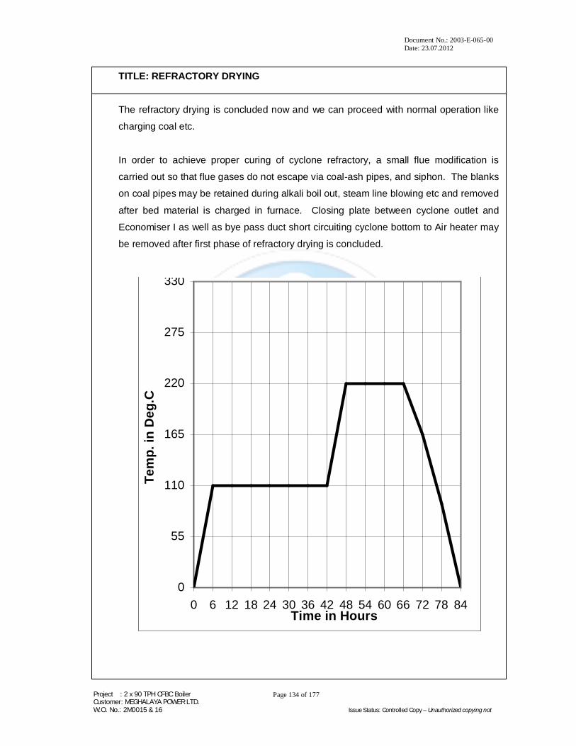
for about 36 hours at this level. This will slowly evaporate the moisture.
Raise the temperature of flue gases by slow increase in oil consumption at the HGG so
that a gradient of 20°C per hour is achieved from 110°C up to 220°C temperature. Soak
the refractory at 220°C approximately for 18 hours.
Shut down the HGG and allow the natural cooling of refractory after 18 hours of soaking
at 220°C. This marks the end of first phase of refractory drying.
Second phase of refractory drying is taken up at the commencement coal/lignite firing.
Raise the bed temperature with the help of HGG at the rate of 15°C per hour when the
bed material is in furnace, which is filled with water. Soaking may be done for approx
12 hours maintaining bed temperature 500°C to 550°C.
Document No.: 2003-E-065-00 Date: 23.07.2012
Project : 2 x 90 TPH CFBC Boiler Customer: MEGHALAYA POWER LTD. W.O. No.: 2M0015 & 16 Issue Status: Controlled Copy – Unauthorized copying not
Page 134 of 177
TITLE: REFRACTORY DRYING
The refractory drying is concluded now and we can proceed with normal operation like
charging coal etc.
In order to achieve proper curing of cyclone refractory, a small flue modification is
carried out so that flue gases do not escape via coal-ash pipes, and siphon. The blanks
on coal pipes may be retained during alkali boil out, steam line blowing etc and removed
after bed material is charged in furnace. Closing plate between cyclone outlet and
Economiser I as well as bye pass duct short circuiting cyclone bottom to Air heater may
be removed after first phase of refractory drying is concluded.
0
55
110
165
220
275
330
0 6 12 18 24 30 36 42 48 54 60 66 72 78 84Time in Hours
Te
mp
. in
De
g.C

Document No.: 2003-E-065-00 Date: 23.07.2012
Project : 2 x 90 TPH CFBC Boiler Customer: MEGHALAYA POWER LTD. W.O. No.: 2M0015 & 16 Issue Status: Controlled Copy – Unauthorized copying not
Page 135 of 177
TITLE: ALKALI BOIL OUT
D14 - 0 - 0 - 0 ALKALI BOIL OUT
Document No.: 2003-E-065-00 Date: 23.07.2012
Project : 2 x 90 TPH CFBC Boiler Customer: MEGHALAYA POWER LTD. W.O. No.: 2M0015 & 16 Issue Status: Controlled Copy – Unauthorized copying not
Page 136 of 177
TITLE: ALKALI BOIL OUT
D14.1.0.0 PURPOSE
The cleaning of internal surfaces of furnace pressure parts is essential to ensure that
during normal operation of steam generation, steam is free from impurities/foreign
particles such as lubricants, oil, rust, sand, metal fragments and assorted debris which
are harmful for steam consumers e.g. steam turbine. This is achieved by boiling
out/circulating alkaline solutions through part of pressure parts.
As preparatory to boil out process, flushing of the boiler is carried out by repeated filling
up of steam generator and draining. Treated (completely desalinated or softened) and
deaerated feed water should be used as filling water for flushing and through out alkali
boil out operation.
D14.2.0.0 CHEMICALS
The following chemicals should be added through steam drum manhole just before
commencement of heating by hot gas generators. Quantities are for each cubic metre
of water in the system.
Anhydrous Trisodium Phosphate (Na3PO4) : 2 kg
OR
Crystalline Trisodium Phosphate (Na3PO4, 12H2O) : 5 kg
OR
Soda Ash (Na2CO3) : 9 kg
1.5 kg to 2 kg of good detergent may also be mixed with water in addition to quantity of
one of the chemicals stated above.
Water holding capacity (up to steam drum centreline) ~ 36 Te.
Provision should be made for double quantities of chemicals. Mostly, two charges of
chemicals may not be necessary.

Document No.: 2003-E-065-00 Date: 23.07.2012
Project : 2 x 90 TPH CFBC Boiler Customer: MEGHALAYA POWER LTD. W.O. No.: 2M0015 & 16 Issue Status: Controlled Copy – Unauthorized copying not
Page 137 of 177
TITLE: ALKALI BOIL OUT
Open the steam drum manhole door and feed water through filling line until water is
about 150 mm below the bottom of steam drum manhole opening. Boiler is lighted up to
raise water temperature to approx. 900C. Dissolve the chemicals thoroughly in hot
water in a suitable tank or container and transfer the solution into the drum via manhole,
ensure the chemicals are evenly distributed across the drum. Do not pour the solution
in empty boiler drum. After charging solution (of chemicals), slowly feed the water in
system to assist mixing. Close and secure drum manhole door and finally take water in
system to bring water level up to approx 100mm below centre-line of gauge glass.
D14.3.0.0 PROCEDURE
Start hot gas generators with fuel at minimum level. Soon after the HGG is switched on,
the boiler is thermally "Alive". During the initial warming up, temperature changes
through out, the unit may indicate places where expansion strains are felt or where
warming up of headers and drum are not occurring uniformly. Keep close watch on
such undesirable developments. The following items should be observed:
1. Thermal expansion of casing and buck-stays.
2. Boiler circulation starts soon after a fire is lit in the combustor. Top headers
and drum will get warmer first to be followed by lower portion of furnace and
bottom headers. In case a particular header or a portion of it shows signs of
non-uniform heating, give number of short blows (max 20secs) through the
header drain /blow down valves until the circulation is observed/noted. Blow
down from each header should be roughly same quantity.
3. Expansion joints remain tight and unrestrained.
4. Boiler is expanding in different directions as desired.
(Trams are already fixed at various levels and locations for monitoring thermal
expansion)
The steam generator is heated up with a firing capacity of approx. 3 to 5% MCR to
reach boiling condition and later on approx. 7% MCR up to about 30 Kg/cm2 (g) working
pressure. Both hot gas generators may be pressed in service for boil out operation.
Start up vent and Super-heater drain will be partially open to maintain pressure and
small circulation. The flue gas temperature at SH3 entry should not exceed 450-480°C
(fuel quantity limitation).

Document No.: 2003-E-065-00 Date: 23.07.2012
Project : 2 x 90 TPH CFBC Boiler Customer: MEGHALAYA POWER LTD. W.O. No.: 2M0015 & 16 Issue Status: Controlled Copy – Unauthorized copying not
Page 138 of 177
TITLE: ALKALI BOIL OUT
Air vents should be shut off as soon as strong blow of steam occurs, at about 2 Kg/cm2
Boiler pressure. (The drum pressure gauges impulse lines may be blown through for
commissioning drum pressure gauge). As the pressure is raised, carefully inspect drum
manhole joints for leaks and tighten where necessary.
The water level in drum will normally increase due to expansion of water and circulation
and occasionally, the level touches top of gauge glass. Under these conditions the
excess water should be removed by operating lower water wall header drain valves. By
removing water from the boiler at this location, circulation can be accelerated.
It is desirable to warm up the boiler by continuous (controlled) firing because circulation
can be maintained continuously, thus assuring uniform heating of all pressure parts and
minimum of stress to them as well as refractory. When raising steam pressure with
intermittent firing, it is possible to arrive at full operating pressure in steam drum and still
have lower portions of boiler, remain relatively cool.
Around 30 kg/cm2(g) pressure in boiler will produce adequate circulation. Maintain this
pressure for 10 hours or longer. It is permissible to throttle vent to conserve fuel.
However ensure that sufficient steam is generated to have active continuous boiling of
solution and corresponding circulation of boiler water.
During boil out, furnace bottom header drain blow down valves should each be opened
for approximately five seconds at after every two hours interval. This will remove
maximum of sludge with minimum of risk of choking the blow down pipe work. Collect
Boiler water sample (CBD sample) for analysis of (a) Phosphate concentration, (b)
Alkalinity, and (c) Oil & Grease content in the sample. During the process, if the
phosphate concentration drops below 2000 ppm, doze additional chemicals through HP
dozing system to restore the original concentration.
Blow down lines should be hot. If not give them additional short blow down until they
become hot. Add clean warm water to bring back normal water level, bring the pressure
back to boil out pressure and continue boiling with steam venting.

Document No.: 2003-E-065-00 Date: 23.07.2012
Project : 2 x 90 TPH CFBC Boiler Customer: MEGHALAYA POWER LTD. W.O. No.: 2M0015 & 16 Issue Status: Controlled Copy – Unauthorized copying not
Page 139 of 177
TITLE: ALKALI BOIL OUT
D14.4.0.0 CLEANING AND INSPECTION
After maintaining the drum pressure around 30 kg/cm² (g) and normal circulation for
about 20 hours, shut down the HGG. Give blow down for longer period. Water level
should be restored and maintained until the boiler cools. When the boiler has finally
cooled, but before zero pressure is reached (say 6Kg/cm2) open all blow down and
drain valves to hot drain the boiler, economiser and super-heater. Open all air vents
when the pressure reaches 2 Kg/cm2. During emptying check that each drain and blow
down is running clear and it is not choked. On completion, feed a little water into the
boiler to wash out any remaining sludge.
Repeat blowing down and refilling the boiler at every two hours intervals. After alkali
boil out, periodically take blow down samples and analyse for oil content, silica, pH,
phosphate, suspended matter and clarity, if laboratory facilities are available. Continue
draining and refilling till quality of circulated water has conductivity within 50 micro-mho
of the incoming water. If analytical equipment is not available, charging and draining
water every two hours can be terminated when clarity or turbidity of drained water is
visibly same as the incoming water.
Inspect the interior of the steam drum, lower water wall headers and all other accessible
internal surfaces. Wash out any loose scale or other residue seen on internal surface of
the drum with high-pressure water hoses. The inspection nipples of furnace bottom
headers and economiser inlet header should be cut to examine bottom headers for left
over sludge/sediment. Remove all foreign material by washing with high-pressure water
hoses. The inspection nipples should now be rewelded and post heat treatment
wherever necessary carried out. Drum internals should now be fixed.
When all cleaning operations are completed and inspection confirms that internal
surfaces are clean, install new gaskets on any gasketed openings that were used for
access.
Unit is now ready for steam line blowing.
It should be the responsibility of nominated competent individual to control water level
(bearing in mind that alarms and remote indicators available in normal service are not
pressed in service during this operation) and rate of change of pressure and
temperature. Adjust drain quantities such that no excessive pressure drop occurs while
opening the drain valves.

Document No.: 2003-E-065-00 Date: 23.07.2012
Project : 2 x 90 TPH CFBC Boiler Customer: MEGHALAYA POWER LTD. W.O. No.: 2M0015 & 16 Issue Status: Controlled Copy – Unauthorized copying not
Page 140 of 177
TITLE: STEAM LINE BLOWING
D15 - 0 - 0 - 0 STEAM LINE BLOWING

Document No.: 2003-E-065-00 Date: 23.07.2012
Project : 2 x 90 TPH CFBC Boiler Customer: MEGHALAYA POWER LTD. W.O. No.: 2M0015 & 16 Issue Status: Controlled Copy – Unauthorized copying not
Page 141 of 177
TITLE: STEAM LINE BLOWING
D15.1.0.0 PURPOSE
High velocity boiler steam is often used to clean the Superheaters and steam piping
which may contain mill scales, and any loose material that may damage the turbine
valves, blades or nozzles. Temporary exhaust piping is attached to the steam line near
the turbine so that the loose material can be discharged into the atmosphere without
allowing it to enter the turbine. After the blowing operation is completed and the
temporary piping is removed, fine mesh screens are often installed at the turbine inlet
and left in place during the preliminary operation or until inspections show no debris
collected on them.
Various piping and valve arrangements are used, but the basic scheme and
requirements are shown in a Figure-1 below.
Document No.: 2003-E-065-00 Date: 23.07.2012
Project : 2 x 90 TPH CFBC Boiler Customer: MEGHALAYA POWER LTD. W.O. No.: 2M0015 & 16 Issue Status: Controlled Copy – Unauthorized copying not
Page 142 of 177
TITLE: STEAM LINE BLOWING
There are certain items that must be incorporated in the design of the temporary piping
and valves on all units. These are:
1. The temporary piping, valves and flanges must be designed for the pressure
used during the blowing periods.
2. The temporary atmospheric exhaust must be well supported to withstand the
reaction forces created during the blowing period.
3. The nozzle should also be directed so that the debris discharged at high velocity
during the blowing period does not endanger personnel and equipment.
4. The temporary exhaust pipe bore should be at least as large as the existing
steam piping so that steam flow is not restricted.
5. All NRV internals, control valves, flow nozzles and orifice plates, if any, in the
blow circuits are to be removed and spool pieces to be provided.
6. All permanent hangers and supports for various lines are to be erected and set
for proper values as per design figures. All locks and restraints are to be
removed from pipelines.
7. The area around the exhaust point should be cordoned off. For warning sound,
prior to blow, siren or public address system can be utilised.
8. Boiler should be ready in all respects including:
a. Interlocks, protections, alarms, annunciation and instruments
b. Chemical dosing system
c. Insulation of furnace and air & flue gas ducts
d. Fire fighting system as per designed scheme
e. Fuel oil firing equipment
9. Chemical cleaning of pressure parts internals must be complete prior to steam
blowing.
10. All drain connecting pipes on MS line are to be left open to atmosphere and are
not to be connected to drain vessel to ensure proper and quick draining. After
checking drain pots for choking, the drain lines are to be connected permanently
to vessels after steam blowing.
Note:
All piping, various supports, exhaust steam regulating valve and other valves connected
to turbine and related to steam blowing are not in TKIIPL's scope unless it is specifically
included in contract.

Document No.: 2003-E-065-00 Date: 23.07.2012
Project : 2 x 90 TPH CFBC Boiler Customer: MEGHALAYA POWER LTD. W.O. No.: 2M0015 & 16 Issue Status: Controlled Copy – Unauthorized copying not
Page 143 of 177
TITLE: STEAM LINE BLOWING
D15.2.0.0 PROCEDURE
One procedure for blowing is to raise the boiler pressure to a value slightly below the
design pressure of the temporary piping, gradually open the steam regulating valve
while increasing the firing rate to maintain pressure during the blow and gradually close
the regulating valve while reducing the firing rate. Long blowing periods can be
maintained with this procedure.
An alternate procedure is to raise boiler pressure to a value slightly below the design
pressure of the temporary piping, shut off the firing, open the regulating valve quickly
and permit the boiler pressure to drop to a pressure which will result in a saturation
temperature drop not exceeding 40ºC, then quickly close the regulating valve. This
procedure results in sudden temperature changes, which helps to loosen scale from
inside the steam piping. However, all the boiler pressure parts are subjected to the
same temperature shock. The 40ºC change in temperature during the blowing period
has been established to prevent excessive stresses to the steam drum. Because of the
limited blowing period permitted by this procedure, a number of blows may be required
to do a thorough cleaning job.
In practice, usually the boiler pressure is raised to 40 kg/cm2. Trip the firing and quickly
open the blow off valve.
Allow drum pressure to drop down to approximately 20 kg/cm2 and quickly close the
blow off valve.
The interval between successive blows will be approximately 2 hours. In a day normally
about 6 to 8 blows maybe given with Overnight shutdown of the boiler for about 8 hrs.
This will help in loosening the Mill scale due to cooling and contraction.
All the permanent main steam piping must be insulated before commencing the steam
blowing operation.
All permanent hangers are in position and pressed in operation after floating.
All equipment and personnel around temporary steam piping/supports must be guarded
against any damage /injury.

Document No.: 2003-E-065-00 Date: 23.07.2012
Project : 2 x 90 TPH CFBC Boiler Customer: MEGHALAYA POWER LTD. W.O. No.: 2M0015 & 16 Issue Status: Controlled Copy – Unauthorized copying not
Page 144 of 177
TITLE: STEAM LINE BLOWING
Observe all of the precautions used for normal start-up and normal operation, namely,
purge the furnace, do not exceed drum temperature differential limits throughout the
pressure raising and blowing periods, and maintain adequate water level in the boiler.
Sufficient feed-water pump capacity and condensate storage must be available to
replace the water loss during the blowing period. The water level in the boiler must be
kept under proper control at all times. The water level will rise sharply at the beginning
of each blow and fall sharply at the ending of each blow with the rate of level change
following the rate of valve openings in the steam lines.
The boiler pressure used for blowing out the line must not exceed, the design pressure
of the temporary piping, valves and flanges. Many operators prefer low-pressure
saturated steam or slightly wet steam at high velocities. Velocities above normal
operating velocities can be obtained with low-pressure steam because of the great
change in specific volume of the steam. Other operators feel that temperature shocks,
along with high velocities are required to loosen scale inside the steam piping.
The colour of the steam discharged to the atmosphere can be used as an indication of
the debris being removed from the piping. The abrasion of aluminium target plates
(used in early stages and polished S.S. target plate is used at later stage) at the end of
the exhaust piping gives an indication of amount of debris removed during the blowing
operation. These target plates can be inspected for progressive abrasion after each
blow or they can be replaced after each blow.
In selecting the blowing pressure, it must be remembered that high velocities are easily
obtained with low pressure but changes in drum water level, on the other hand, are
minimized if higher blowing pressures are used.

Document No.: 2003-E-065-00 Date: 23.07.2012
Project : 2 x 90 TPH CFBC Boiler Customer: MEGHALAYA POWER LTD. W.O. No.: 2M0015 & 16 Issue Status: Controlled Copy – Unauthorized copying not
Page 145 of 177
TITLE: STEAM LINE BLOWING D15.3.0.0 DISTURBANCE FACTOR
Disturbance Factor will be calculated using the formulae:
W2purge X Vpurge
Disturbance Factor (DF) = ------------------------
W2MCR X VMCR
Where,
Wpurge = Mass flow during purge condition. This shall be calculated using
Lapple’s equation for compressible fluids.
Vpurge = Specific volume of steam at purge parameters.
WMCR = Steam flow at MCR
VMCR = Specific volume of steam at MCR.
The value of DF at selected locations should be in the range 1.7 > DF > 1.3
D15.4.0.0 COMPLETION CRITERIA
Steam blowing can be declared complete only after ensuring cleanliness of target plates
mounted in the temporary exhaust pipe.
The highest velocity of steam being at the centre, the effectiveness of steam blowing is
judged by the absolute pitting on the Target plate in the central zone i.e. the area
covered by 3/4th of the diameter.
The piping is considered clean if there are not more than five (5) pitting on the target
plate central zone and the edges are not deformed. Besides there should be no pitting
on the rim zone i.e. the area other than the central zone. This should be achieved on 3
consecutive plates.
Document No.: 2003-E-065-00 Date: 23.07.2012
Project : 2 x 90 TPH CFBC Boiler Customer: MEGHALAYA POWER LTD. W.O. No.: 2M0015 & 16 Issue Status: Controlled Copy – Unauthorized copying not
Page 146 of 177
TITLE: SETTING OF SAFETY VALVES
D16 - 0 - 0 - 0 SETTING OF SAFETY VALVES

Document No.: 2003-E-065-00 Date: 23.07.2012
Project : 2 x 90 TPH CFBC Boiler Customer: MEGHALAYA POWER LTD. W.O. No.: 2M0015 & 16 Issue Status: Controlled Copy – Unauthorized copying not
Page 147 of 177
TITLE: SETTING OF SAFETY VALVES
D16.1.0.0 GENERAL
All safety valves are set for popping pressure and blow down before despatch from
manufacturer's works. However, possibility of slight disturbance from desired settings
cannot be ruled out on account of:
1) Physical layout of inlet and outlet piping, drain connections and supports.
Incorrect layout may generate high stresses and back pressure.
2) Ambient temperature.
3) Quality of steam.
4) Any damage during transit, storage or installation.
5) Rust, dirt or foreign material trapped in safety valve components during
storage.
It is therefore necessary to dismantle the safety valve, service it and assemble it
properly. For this purpose, the operation and maintenance instructions of manufacturer
must be thoroughly studied before setting out to float safety valves. Exact position of
compression nut, upper adjustment ring, lower adjustment ring etc. must be properly
recorded in "as received condition". Ensure same setting after servicing and assembly.
Use "Molykote" to lubricate threaded components and areas recommended by
manufacturer.
D16.2.0.0 PRECAUTIONS AND SAFETY MEASURES:
1) Use earmuffs when you are near to safety valves during adjustment.
2) Do not stand close to discharge pipes of safety valves
3) Gagging of safety valve is must while making ring adjustment.
4) Use hand gloves to protect from hot safety valve
5) Make sure that valve body and discharge elbow is free from external stresses
passed on from discharge piping. Safety valves escape piping supports must
be as per drawing.
6) During the boiler hydraulic test at 1.5 times the design pressure the hydrostatic
plugs must be in place. In addition, gag all safety valves.
7) Under no circumstances, the hydraulic test pressure should exceed design
pressure of the boiler unless hydrostatic plugs are in place.

Document No.: 2003-E-065-00 Date: 23.07.2012
Project : 2 x 90 TPH CFBC Boiler Customer: MEGHALAYA POWER LTD. W.O. No.: 2M0015 & 16 Issue Status: Controlled Copy – Unauthorized copying not
Page 148 of 177
TITLE : SETTING OF SAFETY VALVES
8) Fix the gags on safety valves while raising the system pressure at
approximately 80% of design pressure. Similarly, gags should be removed at
approximately 80% of design pressure while releasing the system pressure. in
our case, design pressure is 120 kg/cm² (g).
9) Drain connections from body of safety valve, exhaust elbow, drip pan and
cover vent up to tundish should not have upward slope in any circumstances.
Ensure correct supporting arrangement for drain piping.
D16.3.0.0 PROCEDURE OF SAFETY VALVES FLOATING
Keep water level in drum approximately 150 mm below NWL.
Light up the boiler and raise the pressure at the normal rate (without exceeding
pressure raising curve limits). Gag all valves, except the one, which is being tried for
checking the setting, when pressure reaches around 80% of pop up pressure of lowest
set valve. Usually the Safety Valve with the highest Set Pressure is floated first.
Position the gags properly and tighten them with only light force applied to the gag stem.
Gagging of safety valves in cold condition or low pressure is risky.
Ensure that no person is within 5 metres radius from specific valve under testing. Tie a
rope to the hand lever of safety valve and pull it clean for hand pop up at around 90 to
95% of rated pressure. Give one or two hand pops to remove any dirt/impurities left in
body/inlet of safety valve.
When safety valves are being floated, the water level should be kept below half gauge
glass, feed water should be available at the regulating valve, and the Superheater
drains should be opened. Raise the boiler pressure and allow the safety valve to lift on
its own. During this period it is advantageous to accelerate pressure-raising rate, for
clean pop. Safety valve may simmer when the boiler pressure is very close to the set
value.
The valves should be individually set within +1% of set pressure. The blow down
should be 3 to 5% of set pressure. In case of deviation, adjustment of compression nut,
upper ring and lower ring should be carried out only after lowering the system pressure
to about 80% of rated value and precisely as per instructions of safety valve
manufacturer.

Document No.: 2003-E-065-00 Date: 23.07.2012
Project : 2 x 90 TPH CFBC Boiler Customer: MEGHALAYA POWER LTD. W.O. No.: 2M0015 & 16 Issue Status: Controlled Copy – Unauthorized copying not
Page 149 of 177
TITLE: SETTING OF SAFETY VALVES
Soon after safety valve floats, kill the fire and open the start up vent (partially) to reduce
the pressure in the boiler. Initially, water level may swell but with each safety valve
floating, fresh warm water will have to be admitted to bring up water level in the drum.
Just in case boiler pressure exceeds 1% beyond set value and even then safety valve
does not pop up, kill the fire and open start up vent partially to reduce the pressure to
about 80% of rated value for carrying out corrections.
Successive floating of same safety valve in the event of unsatisfactory performance viz.
pop up pressure or blow down should be avoided. After the boiler pressure drops to
about 80% of pop up pressure (subsequent to safety valve floating) gags may be
interchanged and second safety valve (for its respective setting) may be tried. This will
save time and allow sufficient cooling of safety valve.
In any case ensure that at least one hour of cooling time is provided between
successive floating of same safety valve.
D16.4.0.0 DEFINITIONS
Set Pressure is that predetermined pressure above the working pressure of the boiler
that gives an adequate margin of pressure difference to prevent unnecessary
simmering. It is the pressure at which the first audible sound of escaping steam is heard
and Not the Pressure at which the valve lifts fully.
Full Lift Pressure is that pressure at which the valve has reached its maximum lift and
is usually within 3% excess of the set pressure.
Closing Pressure is that pressure at which the valve re-sets.
Blow-down is the difference between the set pressure and the closing pressure and
should be within 3 – 5 % of the set pressure.
Blowdown = (Set Pressure) – (Closing Pressure) X 100%
(Set Pressure)

Document No.: 2003-E-065-00 Date: 23.07.2012
Project : 2 x 90 TPH CFBC Boiler Customer: MEGHALAYA POWER LTD. W.O. No.: 2M0015 & 16 Issue Status: Controlled Copy – Unauthorized copying not
Page 150 of 177
TITLE: PRESERVATION OF BOILER
D17 - 0 - 0 - 0 PRESERVATION OF BOILER

Document No.: 2003-E-065-00 Date: 23.07.2012
Project : 2 x 90 TPH CFBC Boiler Customer: MEGHALAYA POWER LTD. W.O. No.: 2M0015 & 16 Issue Status: Controlled Copy – Unauthorized copying not
Page 151 of 177
TITLE: PRESERVATION OF BOILER
D17.1.0.0 INTRODUCTION
The advantages of efficient feed water and boiler water treatment during operation may
be lost if the same diligence is not applied to protect heat transfer surfaces during idle
periods. Protection from corrosion during storage becomes vitally important considering
the number of times the boiler and its auxiliary equipment will be idle during its life. To
minimize the possibility of corrosion, boilers to be put into the storage must be carefully
prepared for the idle period and closely watched during the outage.
There are two methods available for storing the unit i.e. dry storage and wet storage.
Although the wet storage procedure is preferred, factors such as availability of good
quality water, ambient weather conditions, length of storage period, auxiliary supply of
heat etc., may dictate that the dry storage procedure is more practical. When the unit is
required for standby service and must be held for sudden calls for operation and the unit
can be quickly made ready for placing in service, wet storage method is adopted.
D17.2.0.0 DRY STORAGE
When it is known that a boiler is to be idle for a considerable length of time and that a
brief period will be allowed for preparation to return it to service, the dry storage method
is recommended. In this method, the unit is emptied, thoroughly cleaned internally and
externally, dried, and then closed up tight to exclude both moisture and air. Trays of
lime, silica gel, or other moisture absorbent may be placed in the drums to draw off the
moisture in the air trapped by the closing up of the boiler. The following general
procedure is recommended when placing a unit into dry storage:
1. Fire the boiler according to the normal start-up procedure and establish 3.5
kg/cm² (g) drum pressure. Secure the boiler and when the pressure decays to
1.5 kg/cm²(g), drain immediately under air. As soon as possible, open the
drums to allow air to circulate for drying of all internal surfaces. This step is
included for a unit that has been in service and is to be placed into storage.
For a unit, that has never been in service, start with Step 2.

Document No.: 2003-E-065-00 Date: 23.07.2012
Project : 2 x 90 TPH CFBC Boiler Customer: MEGHALAYA POWER LTD. W.O. No.: 2M0015 & 16 Issue Status: Controlled Copy – Unauthorized copying not
Page 152 of 177
TITLE: PRESERVATION OF BOILER 2. If the unit is full of water, drain the unit under air. All non-drainable boiler tubes
and super-heater tubes should be blown with compressed air. If an external
source of heat is available such as a steam coiled air heater, portable heaters,
etc., operate these heaters to assist in drying the internal surfaces. Install a
tray containing moisture absorbent (silica gel is preferred) into the drums. To
insure against overflow of corrosive liquid after the moisture has been
absorbed, the trays should not be more than 3/4 full of dry absorbent. The
amount of moisture absorbent can vary but one Kilogram per Tonne/hour
steam flow capacity is a suggested minimum.
3. Attach a source of nitrogen to the steam drum vent, close all other vents and
drains and pressurize the boiler to 0.7 to 1.0 kg/cm²(g) with nitrogen. The
amount of nitrogen required will vary according to the volume of the unit.
4. With the boiler and super-heater pressurized, alternately open all boiler drains
(including super-heater) to purge air from the unit until pressure decays to zero.
It may be necessary to repeat this process several times to reduce the amount
of oxygen left in the unit to a minimum.
5. The unit should now be stored under 0.3 to 0.7 kg/cm² (g) nitrogen pressure
maintained at the steam drum.
6. We would recommend that periodic inspection of the unit be performed every 3
to 6 months to assure that no corrosive action is taking place and to replenish
the absorbent as required. Since air will enter the unit during this inspection, it
will be necessary to repeat Steps 3 and 4 to expel the air.
CAUTION:
THE UNIT SHOULD BE PROPERLY TAGGED AND THE APPROPRIATE WARNING SIGNS
ATTACHED NOTING THAT THE BOILER IS STORED UNDER NITROGEN PRESSURE AND
THAT COMPLETE EXHAUSTION OF THE NITROGEN MUST OCCUR BEFORE ANYONE
ENTERS THE DRUM. BEFORE ENTERING DRUM, TEST TO PROVE THAT THE OXYGEN
CONCENTRATION IS AT LEAST 19.5 PERCENT.
The above procedure is intended to include the economizer and super-heater.

Document No.: 2003-E-065-00 Date: 23.07.2012
Project : 2 x 90 TPH CFBC Boiler Customer: MEGHALAYA POWER LTD. W.O. No.: 2M0015 & 16 Issue Status: Controlled Copy – Unauthorized copying not
Page 153 of 177
TITLE: PRESERVATION OF BOILER
D17.3.0.0 WET STORAGE
The advantage of employing the wet storage procedure is that the unit is stored
completely wet with the recommended levels of chemicals to eliminate a wet dry
interface where possible corrosion can occur. It is suggested that volatile chemicals be
used to avoid increasing the level of dissolved solids in the water to be used for storage.
In preparing a unit for wet storage, the following procedure is recommended.
1. The unit should be filled with deaerated, demineralised water treated with 200
ppm hydrazine (N2H4) for oxygen removal and sufficient ammonia (NH3) to
attain a pH of 10 (for demineralised water, this will require approximately 10
ppm ammonia).
2. We strongly recommend pre-mixing of the chemicals with the water to insure a
uniform mixture entering the boiler. This can be accomplished by the blend-fill
method, or if possible, by pre-mixing of the chemicals in the condenser. Simply
introducing the chemicals through the drum manhole after established water
level will not insure adequate dispersion of chemicals to all internal surfaces,
unless sufficient heat is delivered to the furnace (i.e. firing the boiler) to induce
natural circulation throughout the boiler.
3. Fill the unit with the treated demineralised water until flooding occurs at the
steam drum vent.
4. Back fill the Superheater with treated demineralised water.
5. A source of low-pressure nitrogen should be connected at the steam drum to
maintain 0.3 to 0.7 kg/cm²(g) pressure to prevent air entering the unit.
CAUTION:
THE UNIT SHOULD BE PROPERLY TAGGED AND THE APPROPRIATE WARNING SIGNS
ATTACHED NOTING THAT THE BOILER IS STORED UNDER NITROGEN PRESSURE AND
THAT COMPLETE EXHAUSTION OF THE NITROGEN MUST OCCUR BEFORE ANYONE
ENTERS THE DRUM. BEFORE ENTERING DRUM, TEST TO PROVE THAT THE OXYGEN
CONCENTRATION IS AT LEAST 19.5 PERCENT.
Document No.: 2003-E-065-00 Date: 23.07.2012
Project : 2 x 90 TPH CFBC Boiler Customer: MEGHALAYA POWER LTD. W.O. No.: 2M0015 & 16 Issue Status: Controlled Copy – Unauthorized copying not
Page 154 of 177
TITLE: PRESERVATION OF BOILER
6. If storage continues into winter, ambient temperatures below the freezing point
of water create a real hazard to the boiler pressure parts and it will be
necessary to provide a means of keeping the unit warm to avoid damage.
7. At some later date when the unit is to be placed into service, the boiler can be
drained to normal start-up water level and placed into operation.
In some cases, an expansion tank or surge tank above the drum and super-heater
elevation may be required to accommodate volume changes due to temperature
changes. The ammonia and hydrazine are not required for short period of storage of
less than two weeks; however, the nitrogen blanket is recommended for the steam drum
and super-heater.
Even with the above procedures, the possibility of corrosion must not be
underestimated. The boiler should be inspected periodically for possible corrosion
damage. Analysis of the boiler water should be conducted periodically and, when
necessary, sufficient chemicals added to establish the proper levels recommended. To
ensure uniform dispersion of the chemicals, it will be necessary to repeat one of the
methods outlined in Step 2.
Super-heaters during out-of-service periods, except when the wet storage method is
used, should always be kept dry and closed from contact with air.
No unit should be stored wet when there is any possibility of a temperature drop to the
freezing point unless sufficient heat can be provided to the unit to eliminate the danger
of water freezing and subsequent damage to pressure parts.
Storage of the pre-boiler piping systems, whether it is wet or dry, can be handled in a
manner similar to those suggested for the boiler.

Document No.: 2003-E-065-00 Date: 23.07.2012
Project : 2 x 90 TPH CFBC Boiler Customer: MEGHALAYA POWER LTD. W.O. No.: 2M0015 & 16 Issue Status: Controlled Copy – Unauthorized copying not
Page 155 of 177
TITLE: PRESERVATION OF BOILER D17.4.0.0 NITROGEN BLANKET
Nitrogen should be introduced through a "T" fitting or one vent (or drain) at each of the
following locations:
1. Drum vents
2. Crossover piping vent between primary and secondary super-heater.
3. Secondary super-heater outlet header connection.
The "T" fitting is to be installed between the pipe (or header) and the vent (or drain)
valve. The nitrogen inlet to the "T" should include a stop valve identical to the vent (or
drain) valve. The stop valve and "T" fitting should be a permanent addition to the
location listed.
The nitrogen required to seal the drainable components may be supplied from a
permanent nitrogen system or portable tanks located near the vent elevations. Due to
differences in plant layout, the owner should choose his own method of piping the
nitrogen, either from their permanent system for from portable tanks, to the vent (or
drain) locations listed.
CAUTION:
THE UNIT SHOULD BE PROPERLY TAGGED AND THE APPROPRIATE WARNING SIGNS
ATTACHED NOTING THAT THE BOILER IS STORED UNDER NITROGEN PRESSURE AND
THAT COMPLETE EXHAUSTION OF THE NITROGEN MUST OCCUR BEFORE ANYONE
ENTERS THE DRUM. BEFORE ENTERING DRUMS TEST TO PROVE THAT THE OXYGEN
CONCENTRATION IS AT LEAST 19.5 PERCENT.
D17.5.0.0 PROTECTION OF EXTERNAL SURFACES Gas side corrosion of an idle boiler can cause considerable damage, especially to the
ash hoppers, expansion joints, dampers, boiler casing, fuel burning equipment, baffles,
and flues and ducts. Flue dust, ash, slag, or cinders from sulphur bearing fuels contain
sulphuric acid. When moisture is added, a dilute acid is formed which is very corrosive.
In preparing the boiler for Storage these accumulations must be removed by either
blowing with air lances, washing with water, scraping, or brushing.
Document No.: 2003-E-065-00 Date: 23.07.2012
Project : 2 x 90 TPH CFBC Boiler Customer: MEGHALAYA POWER LTD. W.O. No.: 2M0015 & 16 Issue Status: Controlled Copy – Unauthorized copying not
Page 156 of 177
TITLE: PRESERVATION OF BOILER
In most cases the deposits cannot be completely removed by mechanical means and
therefore must be neutralized with alkaline water. The alkaline flush should be continued
until the water leaving the boiler is completely neutralized. Litmus paper may be used to
determine the acidity of the wash leaving the boiler.
After the flushing operation has been completed, the boiler should be filled with treated
water and fired with a low sulphur fuel to completely dry the setting.
In areas with extremely corrosive atmosphere, all machined surfaces on fuel burning
equipment should be protected with a preservative coating.

Document No.: 2003-E-065-00 Date: 23.07.2012
Project : 2 x 90 TPH CFBC Boiler Customer: MEGHALAYA POWER LTD. W.O. No.: 2M0015 & 16 Issue Status: Controlled Copy – Unauthorized copying not
Page 157 of 177
TITLE: WATER TREATMENT
D18 - 0 - 0 - 0 WATER TREATMENT

Document No.: 2003-E-065-00 Date: 23.07.2012
Project : 2 x 90 TPH CFBC Boiler Customer: MEGHALAYA POWER LTD. W.O. No.: 2M0015 & 16 Issue Status: Controlled Copy – Unauthorized copying not
Page 158 of 177
TITLE : WATER TREATMENT
D18.1.0.0 INTRODUCTION
The water is taken from raw water reservoir and then it is transferred to water treatment
plant by raw water transfer pumps. Requisite Alums are added. The chlorinated raw
water is then suitably pre-treated prior to feeding to the DM or Softener unit. The pre
Treatment section consist of Chemical dosing and Multi grade filters (MGF). The silica
& turbidity level in the feed water is reduced by filtration. The filters are back washed
after 20 hours of service cycle. (During filter backwash, the DM plant and Softening
plant will be out of service mode and standby is taken into service). The filtered water is
then de-chlorinated with ACF or by stand-by Sodium meta-bi-sulfite dosing. The de-
chlorinated water is then passed to softener and DM stream.
The softening plant consists of Softener exchanger (sodium based ionexchanger), soft
water storage tank and soft water transfer pump sets for cooling water cycle make-up.
The Demineralisation plant consists of RO Plant, Degasser, Degassed Water Tank,
Mixed Bed Exchanger, DM water storage tank and DM water transfer pump sets. The
outlet quality of DM water will correspond to boiler make-up water quality requirement
Maintenance of internal and external surfaces of pressure part tubes/pipes in healthy
condition is essential to achieve high load factor and long life of any boiler. Deposition
of insoluble material on internal surfaces of water and steam tubes/pipes influence heat
transfer adversely and sometimes results in tube failures. Treatment of water should
therefore be in its entirety i.e. from raw water to quality of steam in terms of impurities.
Working pressure of water and steam at different stages also significantly affect rate of
reaction and solubility of chemicals used in water treatment. Higher operating pressure
and temperature of boiler call for further stringent requirements and closer limits on
tolerance. Water treatment system is provided to ensure quality of water at feed water
entry point and also take care of dosing appropriate chemicals at low pressure and high
pressure in steam drum to ensure that impurities are within specified limits given in VGB
or similar internationally accepted code.
Present day practice in water treatment technology suitable for the CIRCOFLUID boilers
generating steam at about 90 to 120 kg/cm²(g) pressure and 500°C plus temperature is
generally discussed in the following pages to serve as guideline only.

Document No.: 2003-E-065-00 Date: 23.07.2012
Project : 2 x 90 TPH CFBC Boiler Customer: MEGHALAYA POWER LTD. W.O. No.: 2M0015 & 16 Issue Status: Controlled Copy – Unauthorized copying not
Page 159 of 177
TITLE : WATER TREATMENT
D18.2.0.0 OXYGEN CORROSION OF INTERNAL SURFACES
Carbon steel is protected by a fundamental iron-water chemical reaction that forms a
protective film of magnetic iron oxide on the internal metal surfaces. A small amount of
iron reacts with water until the protective oxide film is formed. Once the film is
established, the reaction virtually stops and does not resume until the film is disturbed or
removed. If the film is removed chemically or mechanically, the iron-water reaction
starts again to build up the protective oxide. This, of course, removes more iron from
the surface of the boiler parts and if allowed to continue will definitely thin the metal
parts. It is, therefore, very important to maintain boiler water chemistry within close
limits to prevent the chemical removal of the initial protective magnetic iron oxide film on
the internal metal surfaces.
The most common form of corrosion is that caused by the presence of oxygen in the
water-steam cycle. The most logical approach to the prevention of corrosion due to
dissolved oxygen is to eliminate the entrance of oxygen to the cycle as far as possible
and by expelling at the first opportunity the oxygen which has unavoidably entered the
cycle. The most common method of expelling oxygen is by deaerating the feed-water
from heaters or condenser.
It is of the utmost importance that this equipment should function over full load range of
the boiler. Oxygen concentrations at the deaerator outlet should be consistently less
than .007ppm. As a further assurance against the destructive effect of dissolved
oxygen, sufficient quantities of oxygen scavenging chemical compound should be
added to the feed-water after the deaerator to maintain a residual of chemicals in the
boiler water. The residual is an indication that all oxygen has been removed; it is also
available for upset conditions.

Document No.: 2003-E-065-00 Date: 23.07.2012
Project : 2 x 90 TPH CFBC Boiler Customer: MEGHALAYA POWER LTD. W.O. No.: 2M0015 & 16 Issue Status: Controlled Copy – Unauthorized copying not
Page 160 of 177
TITLE : WATER TREATMENT
D18.3.0.0 HYDRAZINE AND SODIUM SULPHITE
Reaction of hydrazine with dissolved oxygen produces nitrogen and water. Even
products of decomposition of hydrazine are volatile and tend to form, alkaline solutions
with water. This, therefore do not increase dissolved solids content in boiler water. The
reaction is of course dependant on hydrazine concentration, temperature and time. Due
to the volatility of hydrazine and its decomposition at elevated temperatures, only a
small residual (a few hundredths of a part per million) can be maintained in the boiler
water. It is apparent that with this small quantity of hydrazine available only minute
amounts of oxygen can be allowed to enter the boiler system.
Sodium sulphite is another chemical commonly used in low-pressure boilers as oxygen
scavenger. Sodium sulphate formed after its reaction with traces of oxygen is relatively
harmless chemical. It is advisable to inject sodium sulphite solution in the feed pipe
downstream of Attemperator take off point and upstream Feed Control station to be
assured that boiler salt does not accumulate in steam circuit after evaporation and at the
same time increase feasibility of oxygen scavenging from feed control station piping,
economiser etc.
Products of thermal decomposition at higher operating pressures of boiler are hydrogen
sulphide and sulphur dioxide.
These will re-dissolve at a point where condensation of steam occurs leading to acidic
condition in water circuit. Hydrazine is therefore preferred as oxygen scavenger in the
boiler operating in the region of 100 bars pressure.

Document No.: 2003-E-065-00 Date: 23.07.2012
Project : 2 x 90 TPH CFBC Boiler Customer: MEGHALAYA POWER LTD. W.O. No.: 2M0015 & 16 Issue Status: Controlled Copy – Unauthorized copying not
Page 161 of 177
TITLE: WATER TREATMENT
D18.4.0.0 pH CONTROL OF CONDENSATE FEEDWATER
In accordance with Table-I, feed-water pH should be controlled in the range of 8.5 - 9.5
to reduce iron and copper pick-up in the condensate - feed-water system. The most
common neutralizing chemicals used for controlling the pH of the condensate - feed-
water are - Ammonia, Morpholine, Cyclohexylamine, and Hydrazine.
These chemicals are volatile alkalizers, which distil with the steam and neutralize trace
acids formed in the condensate. Hydrazine is included with the volatile alkalizers,
besides being an oxygen scavenger; it decomposes at the operating temperature of the
boiler (beginning at 200º C) into ammonia in accordance with the following reaction:
Hydrazine -------- Nitrogen + Hydrogen + Ammonia
2N2H4 -------- N2 + H2 + 2NH3
Experience has shown that the condensate pH, when using hydrazine, will stabilize in
the range of 8.5 -9.5 (due to the ammonia formation) depending upon the residual of
hydrazine maintained at the economiser inlet.
Proper pH control and selection of neutralizing chemical can only be determined by a
critical study of the materials making up the condensate feed-water system and on the
basis of iron and copper concentrations in the feed-water which would be indicative of
the attack on these cycle materials. Limits for iron and copper concentrations in the
feed-water are included in the Table-1 given below.
In general, a high pH (due to the ammonia concentration) is considered more
aggressive to copper bearing alloys but is more protective to the carbon steel surfaces.
Therefore, in a cycle consisting of both carbon steel and the copper bearing materials,
of varying quantities, the proper pH can only be prescribed after some experimentation.

Document No.: 2003-E-065-00 Date: 23.07.2012
Project : 2 x 90 TPH CFBC Boiler Customer: MEGHALAYA POWER LTD. W.O. No.: 2M0015 & 16 Issue Status: Controlled Copy – Unauthorized copying not
Page 162 of 177
TITLE : WATER TREATMENT
Of the above alkalizers, morpholine has the most favourable vapour to liquid distribution
ratio; that is, it readily dissolves in the first condensate forming in the turbine,
condenser, feedwater heaters, etc. Its decomposition temperature is in excess of
520ºC. If higher steam temperatures are encountered, formation of ammonia in the
cycle will increase. The decomposition products of morpholine and cyclohexylamine
yield small quantities of ammonia.
When feed-water or boiler water conditions are changed suddenly and drastically,
temporary upsets may be produced which can be troublesome. Therefore, any changes
such as an alteration in the feed-water treating practice, should be made gradually and
with close observation. When hydrazine feed is first started, initial dosage should be
small and changes in the iron and copper concentration in the feed-water should be
carefully monitored. If iron and copper concentration in the feed-water and boiler water
increase significantly, boiler blow-down should be increased. Since it sometimes
requires days or weeks for conditions to stabilize, results must be observed over a
significant period before effects can be properly evaluated.
D18.5.0.0 CARRY-OVER
The trend toward higher steam pressures and temperatures resulting in higher operating
efficiencies imposes a great demand from steam purification equipment to eliminate
troublesome turbine deposits caused by carry-over. Carry-over may result from
mechanical means and/or vaporization of the boiler water salts.
Mechanical carry-over is the entrainment of small droplets of boiler water in the
separated steam. Since entrained boiler water droplets contains solids in the same
concentration and proportions as the boiler water, the amount of impurities in the steam
contributed by mechanical carry-over is the sum of the products of each impurity in the
boiler water multiplied by the moisture content of the steam.
Vaporous carry-over is the distillation of contaminants directly from the boiler water to
the steam. Unlike mechanical carry-over, vaporous carry-over is selective because the
particular constituent usually represents a different percentage of impurity in the steam
than it does in the boiler water.

Document No.: 2003-E-065-00 Date: 23.07.2012
Project : 2 x 90 TPH CFBC Boiler Customer: MEGHALAYA POWER LTD. W.O. No.: 2M0015 & 16 Issue Status: Controlled Copy – Unauthorized copying not
Page 163 of 177
TITLE: WATER TREATMENT
Total carry-over is the total of the mechanical and vaporous carry-over of all impurities.
Experience has shown that operation is satisfactory if the silica in the steam is
maintained below 25 ppb.
Vaporous carry-over is more difficult to alleviate than mechanical carry-over. The only
obvious way is to reduce chemical concentrations in the boiler water. Every kilogram of
chemicals added to the boiler water must be viewed as a potential source of difficulty.
Among the causes of moisture carry-over are high water level, high total solids content
of the boiler water, high alkalinity, and material. Operation of a boiler at loads in excess
of design rating will provide more cause for carry-over than operation within the design
rating. Sudden load changes will cause more difficulty than operation at steady loads.
D18.6.0.0 INTERNAL DEPOSITS
Internal deposits vary in both their physical and chemical character. They differ in
degree, all are barriers to heat transfer and prevent complete wetting of the tube
surfaces with water. The result is always elevated tube metal temperature.
At one extreme are the very hard and dense deposits, which are impervious to water
and are poor heat conductors. When these form in high heat input zones, the results
are tube failures from overheating.
The failures may be the result of rapid localized overheating where considerable
swelling and thinning of the tube wall has occurred. If the failure is of the long term
overheating, there may be little or no swelling and thinning of the tube.
At the other extreme are soft and porous deposits, which allow boiler water to seep to
the tube surface. The result is a concentration of boiler water constituents at the tube
surface. If the constituents are scale forming, more scale will form. If they consist of
caustic, under deposit corrosion will take place.
Document No.: 2003-E-065-00 Date: 23.07.2012
Project : 2 x 90 TPH CFBC Boiler Customer: MEGHALAYA POWER LTD. W.O. No.: 2M0015 & 16 Issue Status: Controlled Copy – Unauthorized copying not
Page 164 of 177
TITLE: WATER TREATMENT D18.7.0.0 TREATMENT
Much of the art of feed-water treatment is devoted to the elimination of deposit forming
materials and the treatment of those minute quantities, which enter the boiler so as to
render them harmless. Pre-treatment equipment is used to eliminate, in so far as
possible, the deposit forming materials. Internal treatment handles the trace quantities,
which get past the pre-treatment equipment and also protects the boiler against
temporary upsets of the pre-treatment system, condenser leakage and contamination
from the condensate return system. In any case, internal boiler water treatment should
not be substituted for pre-treatment.
D18.8.0.0 PRE-TREATMENT
As operating pressures and percent make-up increase, it is imperative also to increase
the quality of the make-up water. As a guide for extended trouble free operation, the
feed-water quality limits indicated in Table-1 should be closely followed.
The type of pre-treatment necessary to obtain these limits depends almost entirely on
the quality and quantity of make-up water to the system. The type of pre-treatment may
include clarification and filtering, cold or hot lime soda, zerlite softening, demineralizers,
or evaporators.
D18.9.0.0 PRE-TREATMENT OF BOILER WATER TO PREVENT HARMFUL DEPOSITS
For boilers operating in the pressure range of 70kg/cm²(g) and above, more stringent
control is required to obtain the necessary feed-water quality. The make-up water
treatment should be of evaporative or demineralised quality. A demineralising plant has
the advantage of being able to produce high quality water without heat loss. However,
when raw water is particularly high in contaminants, there may be an economic
advantage in using an evaporator. The use of condensate polishing systems to ensure
minimum levels of both dissolved and suspended material in the cycle also provides the
additional advantage of reduced start-up time.

Document No.: 2003-E-065-00 Date: 23.07.2012
Project : 2 x 90 TPH CFBC Boiler Customer: MEGHALAYA POWER LTD. W.O. No.: 2M0015 & 16 Issue Status: Controlled Copy – Unauthorized copying not
Page 165 of 177
TITLE: WATER TREATMENT D18.10.0.0 INTERNAL TREATMENT OF BOILER WATER
There are various methods for the internal treatment of boiler water. A blanket
recommendation of any one method is not realistic. The final decision as to the type of
treatment to be used in a particular boiler should be used on the raw water supply,
history of condenser leakage, the percent of make-up required, the nature of the
condensate returns, and other unique factors. A short summary of the recommended
internal water treatment methods is as follows:
D18.10.1.0 CONVENTIONAL TREATMENT
This type of treatment involves the addition of phosphate and caustic through the
chemical feed line to the steam drum. The caustic is added to the boiler water to
maintain the pH in the range of 10.2-11.2.
The primary purpose of phosphate addition to boiler water is to precipitate the hardness
constituents under the proper pH conditions. The calcium reacts with phosphate to
precipitate calcium phosphate as hydroxyapatite [calcium hydroxyapatite - Ca10 (PO4)6
(OH)2]. This is a flocculent precipitate tending to be less adherent to boiler surfaces
than simple tricalcium phosphate, which is precipitated below a pH of 10.2. Also,
caustic reacts with magnesium to form magnesium hydroxide or brucite [Brucite - Mg
(OH)2]. This precipitate is formed in preference to magnesium phosphate at a pH
above 10.5 and is considered, less adherent than magnesium phosphate.
At the higher pressures, comparatively low phosphate residuals must be maintained in
order to avoid appreciable phosphate hideout. Hideout is the term used to express the
phenomenon of the partial disappearance of phosphate in the boiler water upon
increase in load (drum pressure) and its reappearance upon load reduction. (A change
in phosphate concentration greater than 5 ppm as PO4 between high load and low load
is considered hideout). Phosphate hideout does not appear to be important below 100
bars and, even at this pressure, phosphate concentrations of 12 to 25ppm as PO4 can
be carried without appreciable hideout. When the pressure is increased to 150 bars,
the phosphate concentration must usually be decreased to 5 - 10 ppm as Na3PO4 to
avoid excessive hideout.

Document No.: 2003-E-065-00 Date: 23.07.2012
Project : 2 x 90 TPH CFBC Boiler Customer: MEGHALAYA POWER LTD. W.O. No.: 2M0015 & 16 Issue Status: Controlled Copy – Unauthorized copying not
Page 166 of 177
TITLE: WATER TREATMENT
D18.10.2.0 CO-ORDINATED PHOSPHATE TREATMENT
In this method of treatment, no free caustic is added to the boiler water. Figure 1
graphically shows the phosphate concentration versus the resulting pH when trisodium
phosphate is dissolved in water. Points on this Whirl-Purcell curve (mol ratio = 3.0)
indicate that all the phosphate exists as trisodium phosphate.
Recent laboratory tests show that the crystals, which precipitate from a solution of
trisodium phosphate at elevated temperatures, contains some disodium phosphate and
that the supernatant liquid contains sodium hydroxide. These same tests also indicated
that at mol ratios of 2.6 or less, free hydroxide did not form in the supernatant liquid. To
insure that no free caustic is present, we recommend a boiler water phosphate
concentration, which corresponds to a mol ratio of Na to PO4 of 2.6 as shown in Figure.
When using the regular commercial grades of chemicals, caution should be used in
calculating the weights to add to obtain the proper mol ratios since the phosphates are
in the form of Na3PO4 12H2O, Na2HPO4 7H2O. A mixture of 65 percent Na3PO4
12H2O and 35 percent Na2HPO4 7H2O corresponds to a mol ratio of Na to PO4 of 2.6.
In controlling the phosphate, should the pH be too low, it may be corrected by
increasing the ratio of trisodium to disodium phosphate. If the pH is high, this condition
may be corrected by decreasing this ratio. Figure 2 graphically shows the desired
phosphate concentration for a given operation pressure.
D18.10.3.0 VOLATILE TREATMENT WITH SUPPLEMENTAL PHOSPHATE This type of treatment is identical to the volatile treatment except that a small phosphate
residual is carried. How much phosphate that can be carried without excessive hideout
(greater than 5 ppm) change in phosphate concentration between high load and low
load varies somewhat between boiler units even at the same operating pressure. We,
therefore, recommended 3 - 10 ppm as PO4 as the range of concentrations that will not
produce excessive hideout. Phosphate is added to react with any residual hardness
that may escape the pre-treatment plant. The pH of the feed-water is usually
maintained at a value between 8.5 and 9.5 and the boiler water at a value between 9.0
and 10.0. As traces of impurities enter the cycle with the make up, the phosphate will be
precipitated producing free hydroxide.
Document No.: 2003-E-065-00 Date: 23.07.2012
Project : 2 x 90 TPH CFBC Boiler Customer: MEGHALAYA POWER LTD. W.O. No.: 2M0015 & 16 Issue Status: Controlled Copy – Unauthorized copying not
Page 167 of 177
TITLE : WATER TREATMENT
If supplemental phosphate treatment is used, it will be necessary to add di - or mono -
sodium phosphate to control the free hydroxide. Generally, the free hydroxide should
be maintained within 0 - 1 ppm.
D18.11.0.0 CONTROLS
For safe and efficient operation of boilers over 70 kg/cm² (g) operating pressure it is
necessary to continuously monitor the water quality. Early detection of any
contamination entering the cycle is essential so that immediate corrective action can be
taken before the boiler and its related equipment is damaged.
Electrical conductance, the reciprocal of resistance, affords rapid means of checking for
contamination in a water sample. Electrical conductance of a water sample is the
measure of its ability to conduct an electric current, and can be related to the ionisable
dissolved solids in the water. A single instrument will measure and record important
conductivities of the cycle water, from as many as twenty locations in the system. This
electrical conductivity signal can be used to actuate alarm systems or operate
equipment in the water system. The micromho (1x10⁻⁶ mho) is normally the unit of
measurement. For most salts in low concentrations, 2micromho equal 1ppm
concentration when corrected to 25°C.
Ammonia or amines used for pH control effect the conductivity. To obtain an accurate
indication of the solids, a cation ion exchanger is used to remove the volatile alkalizers
and convert the salts to their corresponding acids. The relationship is 7 micromho equal
1ppm concentration for most salts.
For boilers with operating pressures over 70kg/cm²(g), cation conductivity of the
condensate should normally run between 0.2 to 0.5 micromho. A reading above this
limit indicates the presence of some condenser leakage or contamination from some
other source. The source of the contamination should be investigated and remedied at
the first opportunity.
Dissolved oxygen should be monitored at the condensate pump discharge and the
deaerator outlet. Below 125kg/cm² (g) operating pressure where sulphite oxygen
scavenging and conventional or coordinated water treatment are used, the sulphite
chemical feed pumps are usually adjusted manually based upon the results of periodic
wet chemical analysis.

Document No.: 2003-E-065-00 Date: 23.07.2012
Project : 2 x 90 TPH CFBC Boiler Customer: MEGHALAYA POWER LTD. W.O. No.: 2M0015 & 16 Issue Status: Controlled Copy – Unauthorized copying not
Page 168 of 177
TITLE : WATER TREATMENT
Above 125 kg/cm² (g) operating pressure where hydrazine is used as an oxygen
scavenger and the volatile water treatment is used, the hydrazine pumps can be
controlled by either an analyser or recorder for oxygen hydrazine.
Feed-water pH is monitored at the economizer inlet and the condensate pump
discharge. Chemical injection pumps are usually adjusted manually to maintain the
proper pH for the conventional and coordinated phosphate water treatment systems.
Automated equipment is commercially available for the continuous on-stream analysis
of the critical constituents of the boiler water such as hardness phosphate, iron, copper
and silica. Most laboratory analytical procedures that depend on the development of a
colour and then measuring the intensity of that colour to indicate the concentration of
the constituent in the water sample can be put on an automatic basis.
D18.12.0.0 BLOWING DOWN
In many plants the amount and frequency of blowing down is determined from a
chemical analysis of the continuous blow-down from the boiler and the amount of blow-
down depending upon the quality of feed-water and the amount of steam generated. In
regular operation, economizer and furnace wall headers should never be blown down, in
the ordinary sense, while the unit is in active steam service. Valves on these pressure
parts are provided to serve only as drain valves and should be padlocked closed while
the boiler is in service.
The blow-down valves or any drain valve which permits hot water or steam under
pressure to flow into a relatively cold line should be opened slowly and gradually so that
at least one minute is allowed to open a 40 NB drain line from a 70kg/cm² (g) unit from
the time the hot medium starts coming through until the line is opened fully for the
complete blow. Proportionately more time is required for higher pressure and OD pipes.
If the water level in the gauge glass cannot be seen, by the person operating the blow-
down valves, an assistant should be so stationed that he can observe the level and
signal the completion of the desired amount of the blow-down.

Document No.: 2003-E-065-00 Date: 23.07.2012
Project : 2 x 90 TPH CFBC Boiler Customer: MEGHALAYA POWER LTD. W.O. No.: 2M0015 & 16 Issue Status: Controlled Copy – Unauthorized copying not
Page 169 of 177
TITLE: WATER TREATMENT
The disadvantages of intermittently blowing down, such as the resulting variations of
concentration and the inadvisability of blowing down, large quantities of water while the
boiler is operating at high duty, have brought about an increased use of the continuous
blow-down. This consists of a small size connection with a suitable regulating valve or
orifice, so located that blowing down can be accomplished without adversely affecting
boiler circulation. This method permits discharging a small quantity of water
continuously and allows easy adjustment of the quantity as called for by routine
chemical analysis.
TABLE-1 FEED WATER QUALITY LIMITS
Sl. No. Description Values
1. pH 8.5 - 9.2 * OR 9.3 - 9.5 **
2. Oxygen (ppm) 0.007 (Prefer 0)
3. Fe (ppm) 0.01
4. Cu (ppm) 0.005 Max.
5. SiO2 (ppm) 0.02 - 0.07
Note:
* With Copper alloys in feed-water heaters.
** With Carbon steel feed-water heaters.
RECOMMENDED BOILER WATER CONCENTRATIONS FOR CONVENTIONAL
TREATMENT
Characteristics Unit Value
Conductivity at 25oC Micro Siemens/cm 0.1
pH 9.0 – 10.0
Silica as SiO2 ppm 0.002
Phosphate as PO4 ppm 2

Document No.: 2003-E-065-00 Date: 23.07.2012
Project : 2 x 90 TPH CFBC Boiler Customer: MEGHALAYA POWER LTD. W.O. No.: 2M0015 & 16 Issue Status: Controlled Copy – Unauthorized copying not
Page 170 of 177
TITLE : WATER TREATMENT
CO-ORDINATED PHOSPHATE TREATMENT

Document No.: 2003-E-065-00 Date: 23.07.2012
Project : 2 x 90 TPH CFBC Boiler Customer: MEGHALAYA POWER LTD. W.O. No.: 2M0015 & 16 Issue Status: Controlled Copy – Unauthorized copying not
Page 171 of 177
TITLE : WATER TREATMENT
Co-ordinated Phosphate Treatment Drum Water Phosphate Limits
(Normally not used beyond 110 kg/cm2 pressure)

Document No.: 2003-E-065-00 Date: 23.07.2012
Project : 2 x 90 TPH CFBC Boiler Customer: MEGHALAYA POWER LTD. W.O. No.: 2M0015 & 16 Issue Status: Controlled Copy – Unauthorized copying not
Page 172 of 177
TITLE : WATER TREATMENT
Recommended Silica Concentration In Boiler Water At pH 9.5

Document No.: 2003-E-065-00 Date: 23.07.2012
Project : 2 x 90 TPH CFBC Boiler Customer: MEGHALAYA POWER LTD. W.O. No.: 2M0015 & 16 Issue Status: Controlled Copy – Unauthorized copying not
Page 173 of 177
TITLE : LUBRICATION SCHEDULE
D19 - 0 - 0 - 0 LUBRICATION SCHEDULE
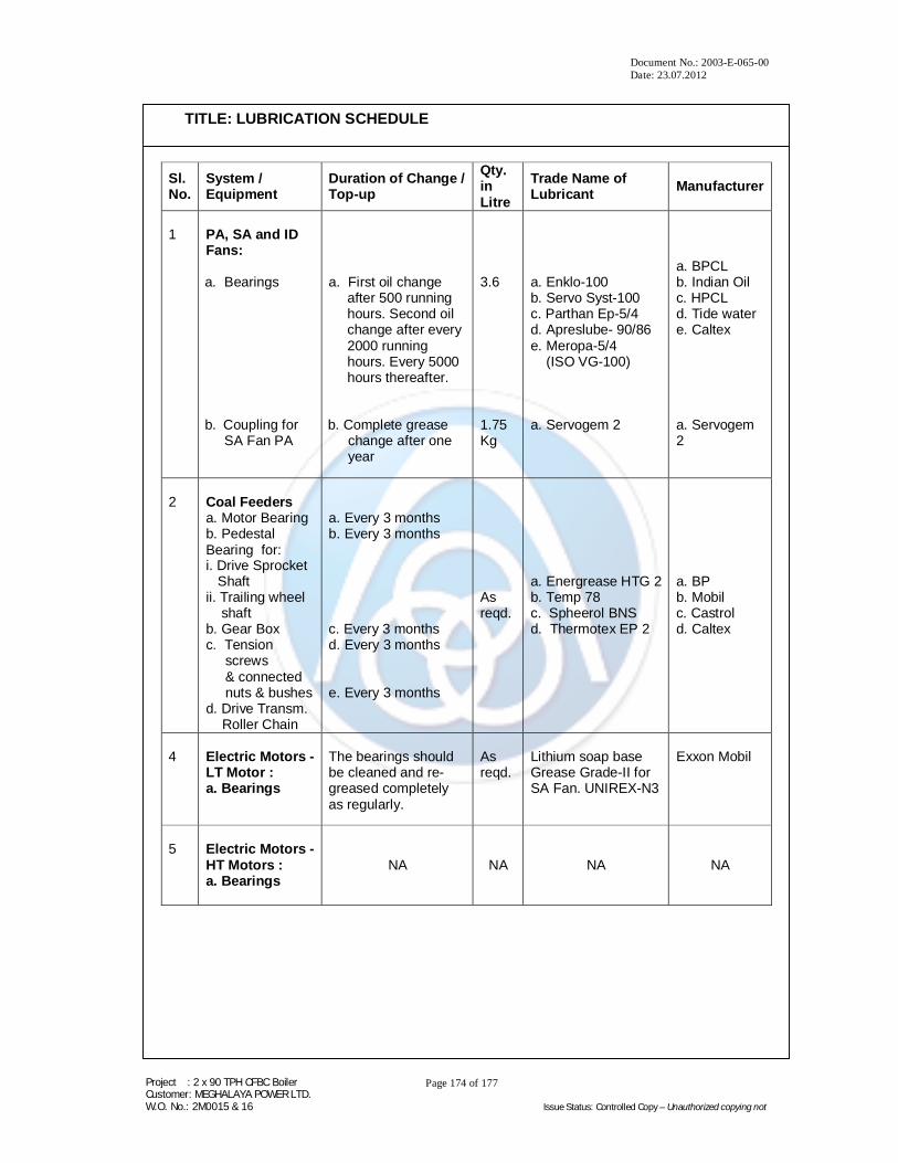
Document No.: 2003-E-065-00 Date: 23.07.2012
Project : 2 x 90 TPH CFBC Boiler Customer: MEGHALAYA POWER LTD. W.O. No.: 2M0015 & 16 Issue Status: Controlled Copy – Unauthorized copying not
Page 174 of 177
TITLE: LUBRICATION SCHEDULE
Sl. No.
System / Equipment
Duration of Change / Top-up
Qty. in Litre
Trade Name of Lubricant Manufacturer
1
PA, SA and ID Fans: a. Bearings b. Coupling for
SA Fan PA
a. First oil change
after 500 running hours. Second oil change after every 2000 running hours. Every 5000 hours thereafter.
b. Complete grease
change after one year
3.6 1.75 Kg
a. Enklo-100 b. Servo Syst-100 c. Parthan Ep-5/4 d. Apreslube- 90/86 e. Meropa-5/4 (ISO VG-100) a. Servogem 2
a. BPCL b. Indian Oil c. HPCL d. Tide water e. Caltex a. Servogem 2
2
Coal Feeders a. Motor Bearing b. Pedestal Bearing for: i. Drive Sprocket Shaft ii. Trailing wheel shaft b. Gear Box c. Tension screws & connected nuts & bushes d. Drive Transm.
Roller Chain
a. Every 3 months b. Every 3 months c. Every 3 months d. Every 3 months e. Every 3 months
As reqd.
a. Energrease HTG 2 b. Temp 78 c. Spheerol BNS d. Thermotex EP 2
a. BP b. Mobil c. Castrol d. Caltex
4
Electric Motors - LT Motor : a. Bearings
The bearings should be cleaned and re-greased completely as regularly.
As reqd.
Lithium soap base Grease Grade-II for SA Fan. UNIREX-N3
Exxon Mobil
5
Electric Motors - HT Motors : a. Bearings
NA
NA NA NA

Document No.: 2003-E-065-00 Date: 23.07.2012
Project : 2 x 90 TPH CFBC Boiler Customer: MEGHALAYA POWER LTD. W.O. No.: 2M0015 & 16 Issue Status: Controlled Copy – Unauthorized copying not
Page 175 of 177
TITLE: LUBRICATION SCHEDULE
6
Electrical Actuators for Dampers and Valves
NA NA NA NA
7
HP Dosing System:
Gear Reservoir of the Pump
Change every 500 hours of operation or every 3 months, whichever is earlier.
0.2 Litres
a. Servosystem 460
b. Enklo 460
a. Indian Oil
b. HPCL
8
Pneumatic Slide Gates for Bed, Cyclone Ash: a. Pneumatic
Actuator b. Gates
a. As and when
dismantled. b. Whenever
excessive operating torque is experienced.
As reqd.
a. Any moly based
grease. b. Any lithium
based grease.
Any std. Manufacturer.
9
Electrical Hoists:
Gears and Bearing
As and when dismantled or whenever excessive operating torque is experienced or once in a year.
As reqd.
Servogem 2
OCL

Document No.: 2003-E-065-00 Date: 23.07.2012
Project : 2 x 90 TPH CFBC Boiler Customer: MEGHALAYA POWER LTD. W.O. No.: 2M0015 & 16 Issue Status: Controlled Copy – Unauthorized copying not
Page 176 of 177
TITLE : BOILER GA DRAWINGS AND P&I DIAGRAMS
E1 - 0 - 0 - 0 BOILER GA DRAWINGS AND P&I DIAGRAMS

Document No.: 2003-E-065-00 Date: 23.07.2012
Project : 2 x 90 TPH CFBC Boiler Customer: MEGHALAYA POWER LTD. W.O. No.: 2M0015 & 16 Issue Status: Controlled Copy – Unauthorized copying not
Page 177 of 177
TITLE: BOILER GA DRAWINGS AND P&I DIAGRAMS
LIST OF DRAWINGS
Sr. No. Drawing Name Drawing No. Rev.
1. G.A. of Boiler PB-10969-0 F
2. Boiler Pressure Parts Assembly(FBB-35) PB-13961-0 A
3. Boiler Pressure Parts Assembly(FBB-36) PB-13963-0 0
4. P & ID of Water and Steam PB-10970 E
5. P & ID of Plant Steam system PB-10971-1 E
6. P & ID of Air / Flue gas PB-10972-1 D
7. P & ID of Fuel PB-10973-2 C
8. P & ID of Ash Handling System PB-10974-1 D
9. P & ID of HP Dosing PB-10975 C
10. P & ID of Hot Gas Generators Attached to HGG Manual
11. P & ID of Cooling water system PB-11919-2 C

![MOTOMAN MPL-series - Technology BSA MPL-series MPL80 MPL100 MPL160 MPL300 MPL500 MPL800 Palletising with the MPL-series Specifications MPL80 Axes Maximum motion range [º] Maximum](https://static.fdocuments.in/doc/165x107/5b0359147f8b9aba168bc128/motoman-mpl-series-technology-bsa-mpl-series-mpl80-mpl100-mpl160-mpl300-mpl500.jpg)