Manual para tuberia de doble contencion
98
Volume III: Acid Waste Piping Systems Industrial Technical Manual Series FIFTH EDITION IPEX ACID WASTE PIPING SYSTEMS Enfield ® Electrofusion Acid Waste System Labline ® Mechanical Joint Acid Waste System Floway TM Acid Resistant Floor Drains Neutratank ® Neutralization Tanks
-
Upload
pedro-rodriguez -
Category
Documents
-
view
63 -
download
8
Transcript of Manual para tuberia de doble contencion
Volume III:Acid WastePiping Systems
Industrial TechnicalManual Series
F I F T H E D I T I O N
IPEX ACID WASTE PIPING SYSTEMS
Enfield® Electrofusion Acid Waste SystemLabline® Mechanical Joint Acid Waste SystemFlowayTM Acid Resistant Floor DrainsNeutratank® Neutralization Tanks

IPEX Acid Waste Piping Systems
Industrial Technical Manual Series
Vol. III, 5th Edition
© 2006 by IPEX. All rights reserved. No part of this book may be used or reproduced in any manner whatsoever without priorwritten permission. For information contact: IPEX, Marketing,2441 Royal Windsor Drive, Mississauga, Ontario, Canada, L5J 4C7. The information contained here within is based on current informationand product design at the time of publication and is subject to changewithout notification. IPEX does not guarantee or warranty the accuracy, suitability for particular applications, or results to be obtained therefrom.

ABOUT IPEX
At IPEX, we have been manufacturing non-metallic pipe and fittings since 1951. We formulate our own compounds andmaintain strict quality control during production. Our products are made available for customers thanks to a network ofregional stocking locations throughout North America. We offer a wide variety of systems including complete lines of piping,fittings, valves and custom-fabricated items.
More importantly, we are committed to meeting our customers’ needs. As a leader in the plastic piping industry, IPEXcontinually develops new products, modernizes manufacturing facilities and acquires innovative process technology. In addition,our staff take pride in their work, making available to customers their extensive thermoplastic knowledge and field experience.IPEX personnel are committed to improving the safety, reliability and performance of thermoplastic materials. We are involved inseveral standards committees and are members of and/or comply with the organizations listed on this page.
For specific details about any IPEX product, contact our customer service department.
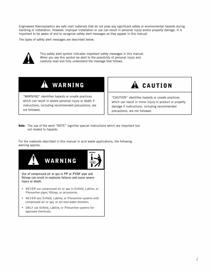
Engineered thermoplastics are safe inert materials that do not pose any significant safety or environmental hazards duringhandling or installation. However, improper installation or use can result in personal injury and/or property damage. It isimportant to be aware of and to recognize safety alert messages as they appear in this manual.
The types of safety alert messages are described below.
This safety alert symbol indicates important safety messages in this manual.When you see this symbol be alert to the possibility of personal injury andcarefully read and fully understand the message that follows.
WARNING CAUTION
Note: The use of the word “NOTE” signifies special instructions which are important but not related to hazards.
“CAUTION” identifies hazards or unsafe practiceswhich can result in minor injury or product or propertydamage if instructions, including recommendedprecautions, are not followed.
“WARNING” identifies hazards or unsafe practiceswhich can result in severe personal injury or death ifinstructions, including recommended precautions, arenot followed.
• NEVER use compressed air or gas in Enfield, Labline, or Plenumline pipes, fittings, or accessories.
• NEVER test Enfield, Labline, or Plenumline systems with compressed air or gas, or air-over-water boosters.
• ONLY use Enfield, Labline, or Plenumline systems for approved chemicals.
Use of compressed air or gas in PP or PVDF pipe andfittings can result in explosive failures and cause severeinjury or death.
i
WARNING
For the materials described in this manual in acid waste applications, the followingwarning applies.
IPEX Acid Waste Piping Systems
CONTENTS
Acid Waste Piping Systems Manual
About IPEX
Safety Alerts . . . . . . . . . . . . . . . . . . . . . . . . . . . . . . . . . . . . . . . . . . . . . . . . .i
Section One: General Information
Overview . . . . . . . . . . . . . . . . . . . . . . . . . . . . . . . . . . . . . . . . . . . . . . . . . . .1
IPEX Acid Waste Systems . . . . . . . . . . . . . . . . . . . . . . . . . . . . . . . . . . . . . . .2
Benefits . . . . . . . . . . . . . . . . . . . . . . . . . . . . . . . . . . . . . . . . . . . . . . . . . . . .4
Material Description . . . . . . . . . . . . . . . . . . . . . . . . . . . . . . . . . . . . . . . . . . .7
Section Two: Dimensions
Pipe Dimensions . . . . . . . . . . . . . . . . . . . . . . . . . . . . . . . . . . . . . . . . . . . . . .9
Enfield Fitting Dimensions . . . . . . . . . . . . . . . . . . . . . . . . . . . . . . . . . . . . .10
Labline and Plenumline Fitting Dimensions . . . . . . . . . . . . . . . . . . . . . . . . .24
Accessories . . . . . . . . . . . . . . . . . . . . . . . . . . . . . . . . . . . . . . . . . . . . . . . .33
Floway Polypropylene Drain Dimensions . . . . . . . . . . . . . . . . . . . . . . . . . . . .35
Standard Bolt Pattern and Dimensions . . . . . . . . . . . . . . . . . . . . . . . . . . . . .39
Section Three: Design Considerations
Expansion and Contraction . . . . . . . . . . . . . . . . . . . . . . . . . . . . . . . . . . . . .41
System Sizing . . . . . . . . . . . . . . . . . . . . . . . . . . . . . . . . . . . . . . . . . . . . . .45
Thermal Conductivity . . . . . . . . . . . . . . . . . . . . . . . . . . . . . . . . . . . . . . . . .45
Pipe Supports and Support Spacing . . . . . . . . . . . . . . . . . . . . . . . . . . . . . .46
Pipe Clips and Hangers . . . . . . . . . . . . . . . . . . . . . . . . . . . . . . . . . . . . . . . .48
Handling and Storage . . . . . . . . . . . . . . . . . . . . . . . . . . . . . . . . . . . . . . . . .51
Below Ground Installation . . . . . . . . . . . . . . . . . . . . . . . . . . . . . . . . . . . . . .52
Section Four: Installation
Introduction . . . . . . . . . . . . . . . . . . . . . . . . . . . . . . . . . . . . . . . . . . . . . . . .53
Standard Enfield Electrofusion . . . . . . . . . . . . . . . . . . . . . . . . . . . . . . . . . .53
Multiple Joint Fusion . . . . . . . . . . . . . . . . . . . . . . . . . . . . . . . . . . . . . . . . .56
Cold Weather Fusion . . . . . . . . . . . . . . . . . . . . . . . . . . . . . . . . . . . . . . . . . .57
Enfield Testing . . . . . . . . . . . . . . . . . . . . . . . . . . . . . . . . . . . . . . . . . . . . . .58
Enfield Pipe Repair . . . . . . . . . . . . . . . . . . . . . . . . . . . . . . . . . . . . . . . . . .59
Labline and Plenumline Joints . . . . . . . . . . . . . . . . . . . . . . . . . . . . . . . . . . .60
Labline and Plenumline Testing . . . . . . . . . . . . . . . . . . . . . . . . . . . . . . . . . .62
iii
Section Five: Additional Engineering Considerations
Return Air Plenum Guidelines . . . . . . . . . . . . . . . . . . . . . . . . . . . . . . . . . . .63
Return Air Plenum Options . . . . . . . . . . . . . . . . . . . . . . . . . . . . . . . . . . . . .64
Adapting to Other Drainline Materials . . . . . . . . . . . . . . . . . . . . . . . . . . . . . .65
Typical Underbench Configurations . . . . . . . . . . . . . . . . . . . . . . . . . . . . . . .66
Section Six: Dilution and Neutralization
Dilution Traps . . . . . . . . . . . . . . . . . . . . . . . . . . . . . . . . . . . . . . . . . . . . . . .69
Neutralization . . . . . . . . . . . . . . . . . . . . . . . . . . . . . . . . . . . . . . . . . . . . . . .70
Cylindrical Tanks . . . . . . . . . . . . . . . . . . . . . . . . . . . . . . . . . . . . . . . . . . . .71
Rectangular Tanks . . . . . . . . . . . . . . . . . . . . . . . . . . . . . . . . . . . . . . . . . . .73
Options and Accessories . . . . . . . . . . . . . . . . . . . . . . . . . . . . . . . . . . . . . . .75
Solids Interception . . . . . . . . . . . . . . . . . . . . . . . . . . . . . . . . . . . . . . . . . . .76
Neutrasystem 2 . . . . . . . . . . . . . . . . . . . . . . . . . . . . . . . . . . . . . . . . . . . . .77
Neutralization, Tank Sizing and Maintenance . . . . . . . . . . . . . . . . . . . . . . . .78
Installation . . . . . . . . . . . . . . . . . . . . . . . . . . . . . . . . . . . . . . . . . . . . . . . . .80
Section Seven: Acid Waste System Specifications
Enfield Specifications . . . . . . . . . . . . . . . . . . . . . . . . . . . . . . . . . . . . . . . . .81
Labline Specifications . . . . . . . . . . . . . . . . . . . . . . . . . . . . . . . . . . . . . . . . .82
Plenumline Specifications . . . . . . . . . . . . . . . . . . . . . . . . . . . . . . . . . . . . . .83
Neutratank Neutralization Tank Specifications . . . . . . . . . . . . . . . . . . . . . . . .84
Monitoring System Specifications . . . . . . . . . . . . . . . . . . . . . . . . . . . . . . . .84
Encase Double Containment Acid Waste Systems . . . . . . . . . . . . . . . . . . . . .85
Appendix: Conversion Charts . . . . . . . . . . . . . . . . . . . . . . . . . . . . . . . . . . . . . . . . . . . .86
Information Order Form . . . . . . . . . . . . . . . . . . . . . . . . . . . . . . . . . . . . . . . .88
iv IPEX Acid Waste Piping Systems

NOTES
______________________________________________________
______________________________________________________
______________________________________________________
______________________________________________________
______________________________________________________
______________________________________________________
______________________________________________________
______________________________________________________
______________________________________________________
______________________________________________________
______________________________________________________
______________________________________________________
______________________________________________________
______________________________________________________
______________________________________________________
______________________________________________________
______________________________________________________
______________________________________________________
______________________________________________________
______________________________________________________
______________________________________________________
______________________________________________________
______________________________________________________
______________________________________________________
______________________________________________________
______________________________________________________
______________________________________________________
______________________________________________________
______________________________________________________
______________________________________________________
______________________________________________________
______________________________________________________
______________________________________________________
______________________________________________________
GEN
ERAL
INFORM
ATION
1IPEX Acid Waste Piping Systems
OVERVIEW
SECTION ONE: GENERAL INFORMATION
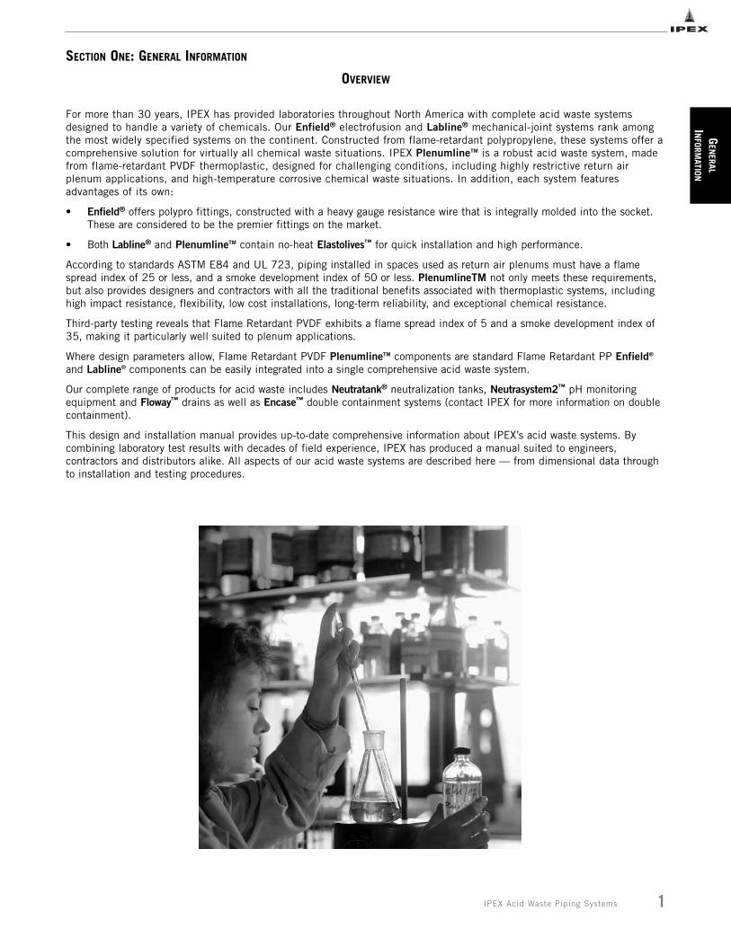
For more than 30 years, IPEX has provided laboratories throughout North America with complete acid waste systemsdesigned to handle a variety of chemicals. Our Enfield® electrofusion and Labline® mechanical-joint systems rank amongthe most widely specified systems on the continent. Constructed from flame-retardant polypropylene, these systems offer acomprehensive solution for virtually all chemical waste situations. IPEX PlenumlineTM is a robust acid waste system, madefrom flame-retardant PVDF thermoplastic, designed for challenging conditions, including highly restrictive return airplenum applications, and high-temperature corrosive chemical waste situations. In addition, each system featuresadvantages of its own:
• Enfield® offers polypro fittings, constructed with a heavy gauge resistance wire that is integrally molded into the socket. These are considered to be the premier fittings on the market.
• Both Labline® and PlenumlineTM contain no-heat Elastolives™ for quick installation and high performance.
According to standards ASTM E84 and UL 723, piping installed in spaces used as return air plenums must have a flamespread index of 25 or less, and a smoke development index of 50 or less. PlenumlineTM not only meets these requirements,but also provides designers and contractors with all the traditional benefits associated with thermoplastic systems, includinghigh impact resistance, flexibility, low cost installations, long-term reliability, and exceptional chemical resistance.
Third-party testing reveals that Flame Retardant PVDF exhibits a flame spread index of 5 and a smoke development index of35, making it particularly well suited to plenum applications.
Where design parameters allow, Flame Retardant PVDF PlenumlineTM components are standard Flame Retardant PP Enfield®
and Labline® components can be easily integrated into a single comprehensive acid waste system.
Our complete range of products for acid waste includes Neutratank® neutralization tanks, Neutrasystem2™ pH monitoringequipment and Floway™ drains as well as Encase™ double containment systems (contact IPEX for more information on doublecontainment).
This design and installation manual provides up-to-date comprehensive information about IPEX’s acid waste systems. Bycombining laboratory test results with decades of field experience, IPEX has produced a manual suited to engineers,contractors and distributors alike. All aspects of our acid waste systems are described here — from dimensional data throughto installation and testing procedures.
GEN
ERAL
INFO
RMAT
ION
2 IPEX Acid Waste Piping Systems
IPEX ACID WASTE SYSTEMS
The IPEX Solution
Changing governmentregulations and increasingpublic desire to minimize environmental pollution hasnecessitated changes in theway chemicals are discharged from industrial andcommercial facilities.
IPEX has long been recognizedfor having the highest quality,most reliable and mostcomprehensive chemical wastesystems available. Whether the problem at hand hasnecessitated the fast andversatile Labline® orPlenumlineTM MechanicalJoint piping systems, or themicroprocessor-controlledEnfield® jointed system, the endresult has been repeatable,trouble-free installations. Froman environmental perspective,IPEX manufactures a patented,modular construction doublecontainment piping system,(EncaseTM, for more information,see Double Containment PipingSystems Manual, Volume VI),that can be used above andbelow ground to eliminate thepossibility of chemical spillageinto the environment.Neutratank® is used forlimestone neutralization ofchemical waste prior todischarge into the sewer.
While this method ofneutralization is very effective,there is a growing need to verify that the chemicaldischarge is continuouslywithin acceptable pH levels.Neutrasystem 2 meets thisneed by analyzing the pH ofliquid flow, permanentlyrecording the pH levelsencountered, and giving visualand audible alarms to warnmaintenance personnel whenthe pH level is outside of the acceptable range.
Maintenance personnel canthen address the situationusually by inserting additional
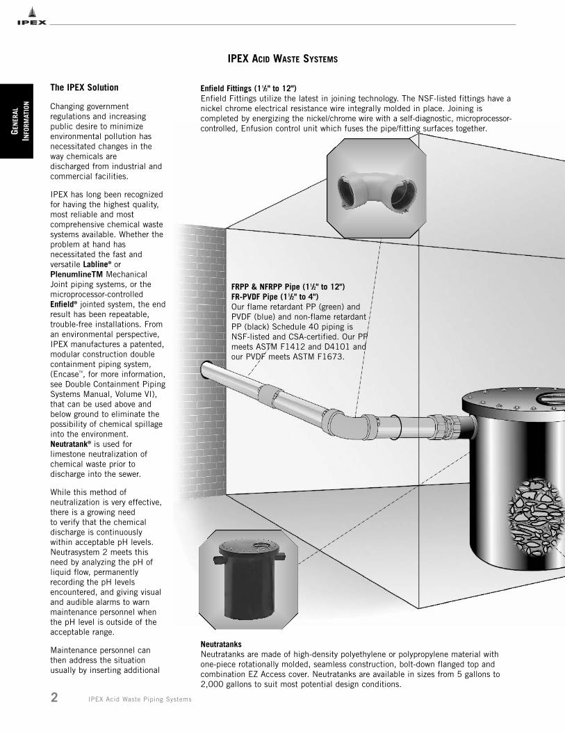
FRPP & NFRPP Pipe (11/2" to 12")FR-PVDF Pipe (11/2" to 4")Our flame retardant PP (green) andPVDF (blue) and non-flame retardantPP (black) Schedule 40 piping isNSF-listed and CSA-certified. Our PPmeets ASTM F1412 and D4101 andour PVDF meets ASTM F1673.
Enfield Fittings (11/2" to 12")Enfield Fittings utilize the latest in joining technology. The NSF-listed fittings have anickel chrome electrical resistance wire integrally molded in place. Joining iscompleted by energizing the nickel/chrome wire with a self-diagnostic, microprocessor-controlled, Enfusion control unit which fuses the pipe/fitting surfaces together.
NeutratanksNeutratanks are made of high-density polyethylene or polypropylene material with one-piece rotationally molded, seamless construction, bolt-down flanged top andcombination EZ Access cover. Neutratanks are available in sizes from 5 gallons to2,000 gallons to suit most potential design conditions.
GEN
ERAL
INFORM
ATION
3IPEX Acid Waste Piping Systems
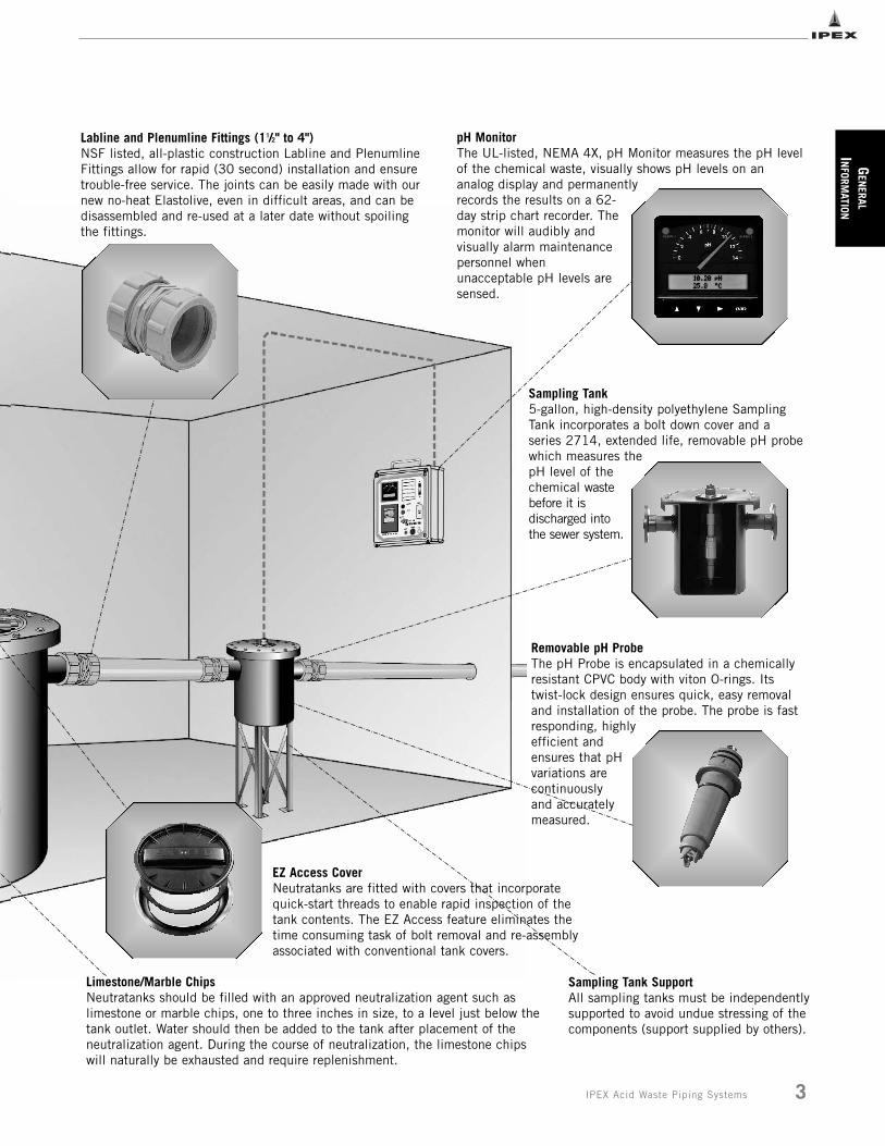
Sampling Tank5-gallon, high-density polyethylene SamplingTank incorporates a bolt down cover and aseries 2714, extended life, removable pH probewhich measures thepH level of thechemical wastebefore it isdischarged intothe sewer system.
Removable pH Probe The pH Probe is encapsulated in a chemicallyresistant CPVC body with viton O-rings. Itstwist-lock design ensures quick, easy removaland installation of the probe. The probe is fastresponding, highlyefficient andensures that pHvariations arecontinuouslyand accuratelymeasured.
Labline and Plenumline Fittings (11/2" to 4")NSF listed, all-plastic construction Labline and PlenumlineFittings allow for rapid (30 second) installation and ensuretrouble-free service. The joints can be easily made with ournew no-heat Elastolive, even in difficult areas, and can bedisassembled and re-used at a later date without spoilingthe fittings.
Limestone/Marble ChipsNeutratanks should be filled with an approved neutralization agent such aslimestone or marble chips, one to three inches in size, to a level just below thetank outlet. Water should then be added to the tank after placement of theneutralization agent. During the course of neutralization, the limestone chipswill naturally be exhausted and require replenishment.
Sampling Tank SupportAll sampling tanks must be independentlysupported to avoid undue stressing of thecomponents (support supplied by others).
pH MonitorThe UL-listed, NEMA 4X, pH Monitor measures the pH levelof the chemical waste, visually shows pH levels on ananalog display and permanentlyrecords the results on a 62-day strip chart recorder. Themonitor will audibly andvisually alarm maintenancepersonnel whenunacceptable pH levels aresensed.
EZ Access CoverNeutratanks are fitted with covers that incorporatequick-start threads to enable rapid inspection of thetank contents. The EZ Access feature eliminates thetime consuming task of bolt removal and re-assemblyassociated with conventional tank covers.
CONTROL UNIT
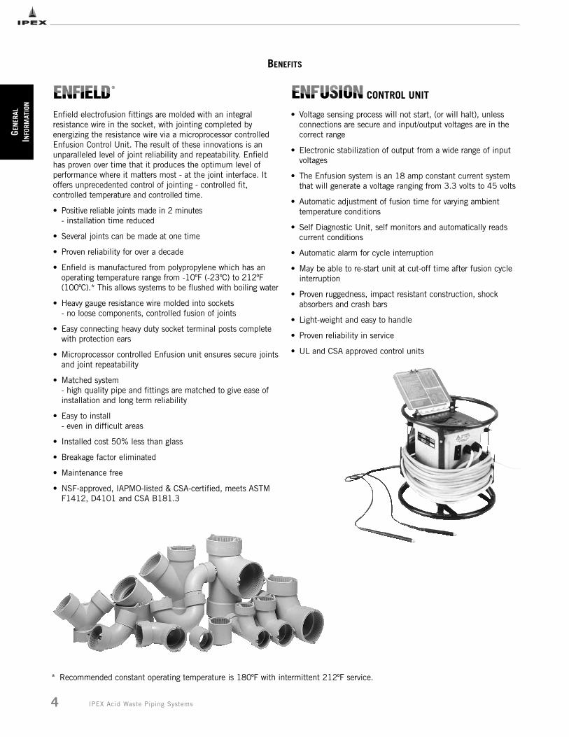
Enfield electrofusion fittings are molded with an integralresistance wire in the socket, with jointing completed byenergizing the resistance wire via a microprocessor controlledEnfusion Control Unit. The result of these innovations is anunparalleled level of joint reliability and repeatability. Enfieldhas proven over time that it produces the optimum level ofperformance where it matters most - at the joint interface. Itoffers unprecedented control of jointing - controlled fit,controlled temperature and controlled time.
• Positive reliable joints made in 2 minutes- installation time reduced
• Several joints can be made at one time
• Proven reliability for over a decade
• Enfield is manufactured from polypropylene which has an operating temperature range from -10ºF (-23ºC) to 212ºF (100ºC).* This allows systems to be flushed with boiling water
• Heavy gauge resistance wire molded into sockets- no loose components, controlled fusion of joints
• Easy connecting heavy duty socket terminal posts complete with protection ears
• Microprocessor controlled Enfusion unit ensures secure jointsand joint repeatability
• Matched system- high quality pipe and fittings are matched to give ease of installation and long term reliability
• Easy to install- even in difficult areas
• Installed cost 50% less than glass
• Breakage factor eliminated
• Maintenance free
• NSF-approved, IAPMO-listed & CSA-certified, meets ASTM F1412, D4101 and CSA B181.3
• Voltage sensing process will not start, (or will halt), unless connections are secure and input/output voltages are in the correct range
• Electronic stabilization of output from a wide range of input voltages
• The Enfusion system is an 18 amp constant current system that will generate a voltage ranging from 3.3 volts to 45 volts
• Automatic adjustment of fusion time for varying ambient temperature conditions
• Self Diagnostic Unit, self monitors and automatically reads current conditions
• Automatic alarm for cycle interruption
• May be able to re-start unit at cut-off time after fusion cycle interruption
• Proven ruggedness, impact resistant construction, shock absorbers and crash bars
• Light-weight and easy to handle
• Proven reliability in service
• UL and CSA approved control units
GEN
ERAL
INFO
RMAT
ION
BENEFITS
4 IPEX Acid Waste Piping Systems
* Recommended constant operating temperature is 180ºF with intermittent 212ºF service.
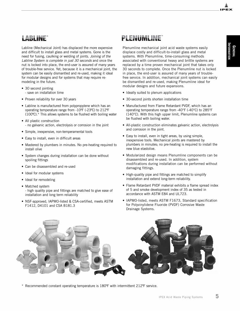
Labline (Mechanical Joint) has displaced the more expensiveand difficult to install glass and metal systems. Gone is theneed for fusing, caulking or welding of joints. Joining of theLabline System is complete in just 30 seconds and once thenut is locked into place, the end-user is assured of many yearsof trouble-free service. Yet, because it is a mechanical joint, thesystem can be easily dismantled and re-used, making it idealfor modular designs and for systems that may require re-modeling in the future.
• 30 second jointing- save on installation time
• Proven reliability for over 30 years
• Labline is manufactured from polypropylene which has an operating temperature range from -10ºF (-23ºC) to 212ºF (100ºC).* This allows systems to be flushed with boiling water
• All plastic construction- no galvanic action, electrolysis or corrosion in the joint
• Simple, inexpensive, non-temperamental tools
• Easy to install, even in difficult areas
• Mastered by plumbers in minutes. No pre-heating required toinstall olive
• System changes during installation can be done without spoiling fittings
• Can be disassembled and re-used
• Ideal for modular systems
• Ideal for remodeling
• Matched system- high quality pipe and fittings are matched to give ease of installation and long term reliability
• NSF-approved, IAPMO-listed & CSA-certified, meets ASTM F1412, D4101 and CSA B181.3
GEN
ERAL
INFORM
ATION
5IPEX Acid Waste Piping Systems
Plenumline mechanical joint acid waste systems easilydisplace costly and difficult-to-install glass and metalsystems. With Plenumline, time-consuming methodsassociated with conventional heavy and brittle systems arereplaced by a time proven mechanical joint that takes only30 seconds to complete. Once the Plenumline nut is lockedin place, the end-user is assured of many years of trouble-free service. In addition, mechanical joint systems can easilybe dismantled and re-used, making Plenumline ideal formodular designs and future expansions.
• Ideally suited to plenum applications
• 30-second joints shorten installation time
• Manufactured from Flame Retardant PVDF, which has anoperating temperature range from -40°F (-40°C) to 285°F(140°C). With this high upper limit, Plenumline systems canbe flushed with boiling water.
• All-plastic construction eliminates galvanic action, electrolysisand corrosion in the joint.
• Easy to install, even in tight areas, by using simple,inexpensive tools. Mechanical joints are mastered byplumbers in minutes; no pre-heating is required to install thenew blue elastolive.
• Modularized design means Plenumline components can bedisassembled and re-used. In addition, systemmodifications during installation can be performed withoutdamaging fittings.
• High-quality pipe and fittings are matched to simplifyinstallation and extend long-term reliability.
• Flame Retardant PVDF material exhibits a flame spread indexof 5 and smoke development index of 35 as tested inaccordance with ASTM E84 and UL723.
• IAPMO-listed, meets ASTM F1673, Standard specificationfor Polyvinylidene Fluoride (PVDF) Corrosive WasteDrainage Systems.
* Recommended constant operating temperature is 180ºF with intermittent 212ºF service.
6 IPEX Acid Waste Piping Systems
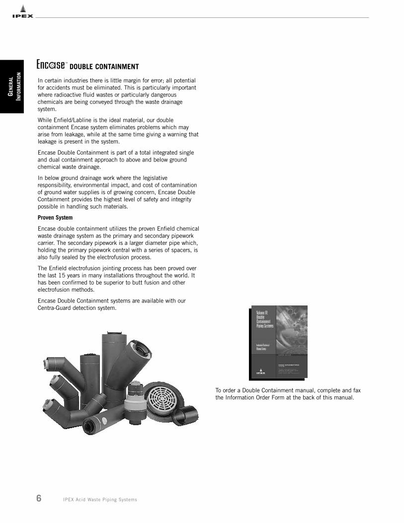
In certain industries there is little margin for error; all potentialfor accidents must be eliminated. This is particularly importantwhere radioactive fluid wastes or particularly dangerouschemicals are being conveyed through the waste drainagesystem.
While Enfield/Labline is the ideal material, our doublecontainment Encase system eliminates problems which mayarise from leakage, while at the same time giving a warning thatleakage is present in the system.
Encase Double Containment is part of a total integrated singleand dual containment approach to above and below groundchemical waste drainage.
In below ground drainage work where the legislativeresponsibility, environmental impact, and cost of contaminationof ground water supplies is of growing concern, Encase DoubleContainment provides the highest level of safety and integritypossible in handling such materials.
Proven System
Encase double containment utilizes the proven Enfield chemicalwaste drainage system as the primary and secondary pipeworkcarrier. The secondary pipework is a larger diameter pipe which,holding the primary pipework central with a series of spacers, isalso fully sealed by the electrofusion process.
The Enfield electrofusion jointing process has been proved overthe last 15 years in many installations throughout the world. Ithas been confirmed to be superior to butt fusion and otherelectrofusion methods.
Encase Double Containment systems are available with ourCentra-Guard detection system.
DOUBLE CONTAINMENT
To order a Double Containment manual, complete and faxthe Information Order Form at the back of this manual.
GEN
ERAL
INFO
RMAT
ION
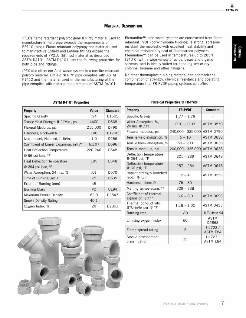
MATERIAL DESCRIPTION
IPEX’s flame retardant polypropylene (FRPP) material used tomanufacture Enfield pipe exceeds the requirements ofPP110 (pipe). Flame retardant polypropylene material usedto manufacture Enfield and Labline fittings exceed therequirements of PP210 (fittings) material as described inASTM D4101. ASTM D4101 lists the following properties forboth pipe and fittings.
IPEX also offers our Acid Waste system in a non-fire retardantpolypro material. Enfield NFRPP pipe complies with ASTMF1412 and the material used in the manufacturing of thepipe complies with material requirements of ASTM D4101.
Property
Specific Gravity
Tensile Yield Strength @ 2"/Min., psi
Flexural Modulus, psi
Hardness, Rockwell R
Izod Impact, Notched, ft-lb/in.
Coefficient of Linear Expansion, in/in/ºF
Heat Deflection Temperature
@ 66 psi load, ºF
Heat Deflection Temperature
@ 264 psi load, ºF
Water Absorption. 24 hrs., %
Time of Burning (sec.)
Extent of Burning (mm)
Burning Class
Maximum Smoke Density
Smoke Density Rating
Oxygen Index, %
Value
.94
4400
215,000
100
1.0
6x10⁻⁵
220-240
195
.01
<5
<5
V2
62.0
40.1
28
Standard
D1505
D638
D790
D1706
D256
D696
D648
D648
D570
D635
UL94
D2843
D2863
7IPEX Acid Waste Piping Systems
ASTM D4101 Properties
GEN
ERAL
INFORM
ATION
Plenumline™ acid waste systems are constructed from flame-retardant PVDF (polyvinylidene fluoride), a strong, abrasion-resistant thermoplastic with excellent heat stability andchemical resistance typical of fluorocarbon polymers.Plenumline™ can be used in temperatures up to 285°F(140°C) with a wide variety of acids, bases and organicsolvents, and is ideally suited for handling wet or drychlorine, bromine and other halogens.
No other thermoplastic piping material can approach thecombination of strength, chemical resistance and operatingtemperature that FR-PVDF piping systems can offer.
Physical Properties of FR-PVDF
Property FR-PVDF Standard
Specific Gravity 1.77 – 1.79 -
Water Absorption, %, 24 hrs. @ 73ºF
0.01 – 0.03 ASTM D570
Flexural modulus, psi 240,000 - 335,000 ASTM D790
Tensile yield elongation, % 5 – 10 ASTM D638
Tensile break elongation, % 50 – 200 ASTM D638
Tensile modulus, psi 200,000 - 335,000 ASTM D638
Deflection temperature @ 264 psi, °F
221 – 239 ASTM D648
Deflection temperature @ 66 psi, °F
257 – 284 ASTM D648
Impact strength (notchedIzod), ft-lb/in.
2 – 4 ASTM D256
Hardness, shore D 76 – 80
Melting temperature, °F 329 – 338
Coefficient of thermalexpansion, 10-5 °F
6.6 – 8.0 ASTM D696
Thermal conductivity,BTU-in/hr per ft2 °F
1.18 – 1.32 ASTM D433
Burning rate V-0 UL/Bulletin 94
Limiting oxygen index 60ASTMD2868
Flame spread rating 5UL723 /
ASTM E84Smoke developmentclassification
35UL723 /
ASTM E84
GEN
ERAL
INFO
RMAT
ION
8 IPEX Acid Waste Piping Systems
Chemical Resistance
Thermoplastics have outstanding resistance to a wide rangeof chemical reagents. Such resistance is a function of bothtemperature and concentration, and there are many reagentswhich can be handled for limited temperature ranges andconcentrations.
Chemical resistance is often affected (and frequentlyreduced) when handling a number of chemicals orcompounds containing impurities. When specific applicationsare being considered, therefore, it is often worthwhile toconduct tests using the actual fluid that will be used inservice.
PP is generally high in chemical resistance. It is capable ofhandling a pH ranging from 1 to 13 being resistant toorganic solvents as well as acids and alkalies. Due to itsgeneral sensitivity to oxidizing agents, special care must betaken when using it with strong acids and hydrocarbonscontaining helides and aromatic groups.
Many factors can affect the chemical resistance of materials.These include, but are not limited to, exposure time,concentration of chemical, extremes of temperature,frequency of temperature cycling, attrition due to abrasiveparticles, and the type of mechanical stress imposed. Thefact that certain combinations of chemicals and mechanicalload can induce stress cracking in many otherwise chemicallyresistant materials, both metallic and nonmetallic, is ofparticular significance. In general, the broader molecularweight distribution of Plenumline FR-PVDF resin will result ingreater resistance to stress cracking.
In borderline cases, there may be limited attack, generallyresulting in some swelling due to absorption. There are alsomany cases where some attack will occur under specificconditions. For such applications, the use of plastic is oftenjustified on economic grounds when considered againstalternative materials.
To order a Chemical Resistance Guide or obtain moreinformation, complete and fax the order form at the back ofthis manual.
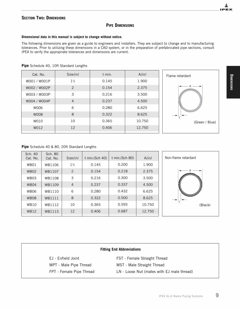
PIPE DIMENSIONS
Dimensional data in this manual is subject to change without notice.
The following dimensions are given as a guide to engineers and installers. They are subject to change and to manufacturingtolerances. Prior to utilizing these dimensions in a CAD system, or in the preparation of prefabricated pipe sections, consultIPEX to verify the appropriate tolerances and dimensions are current.
Cat. No.
WB01
WB02
WB03
WB04
WB06
WB08
WB10
WB12
Size(in)
11/2
2
3
4
6
8
10
12
t min.(Sch 40)
0.145
0.154
0.216
0.237
0.280
0.322
0.365
0.406
A(in)
1.900
2.375
3.500
4.500
6.625
8.625
10.750
12.750
Cat. No.
WB1106
WB1107
WB1108
WB1109
WB1110
WB1111
WB1112
WB1113
t min.(Sch 80)
0.200
0.218
0.300
0.337
0.432
0.500
0.593
0.687
Cat. No.
W001 / W001P
W002 / W002P
W003 / W003P
W004 / W004P
W006
W008
W010
W012
Size(in)
11/2
2
3
4
6
8
10
12
t min.
0.145
0.154
0.216
0.237
0.280
0.322
0.365
0.406
A(in)
1.900
2.375
3.500
4.500
6.625
8.625
10.750
12.750
t
A
t
A
Flame retardant
Pipe Schedule 40, 10ft Standard Lengths
Pipe Schedule 40 & 80, 20ft Standard Lengths
Non-flame retardant
(Black)
Fitting End Abbreviations
EJ - Enfield Joint FST - Female Straight Thread
MPT - Male Pipe Thread MST - Male Straight Thread
FPT - Female Pipe Thread LN - Loose Nut (mates with EJ male thread)
(Green / Blue)
Sch. 40 Sch. 80
SECTION TWO: DIMENSIONS
DIM
ENSION
S
9IPEX Acid Waste Piping Systems
DIM
ENSI
ONS
10 IPEX Acid Waste Piping Systems
B
A
2 1/8"
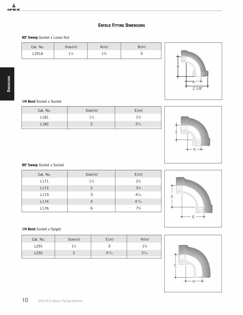
Cat. No.
L291A
90º Sweep Socket x Loose Nut
Size(in)
11/2
A(in)
13/4
B(in)
3
Cat. No.
L291
L292
Size(in)
11/2
2
E(in)
3
313/16
H(in)
13/4
25/16
E
E
E
E
ENFIELD FITTING DIMENSIONS
Cat. No.
L181
L182
1/4 Bend Socket x Socket
Size(in)
11/2
2
E(in)
13/4
25/16
Cat. No.
L171
L172
L173
L174
L176
90º Sweep Socket x Socket
Size(in)
11/2
2
3
4
6
E(in)
23/4
31/4
41/16
415/16
73/4
1/4 Bend Socket x Spigot
E
H

DIM
ENSION
S
11IPEX Acid Waste Piping Systems
ENFIELD FITTING DIMENSIONS
Cat. No.
L281
L282
L283
L284
L286
Size(in)
11/2
2
3
4
6
D(in)
23/4
31/4
41/16
415/16
73/4
E(in)
4
45/8
53/4
63/4
93/4
90º Sweep Socket x Spigot
E
D
Cat. No.
L191
L192
L193
L194
L196
Size(in)
11/2
2
3
4
6
D(in)
11/8
11/2
2
2
111/16
1/8 Bend Socket x Socket
D
D
Cat. No.
L211
L212
L213
L214
L216
Size(in)
11/2
2
3
4
6
D(in)
11/8
11/2
2
2
111/16
F(in)
21/4
3
33/4
315/16
45/8
1/8 Bend Socket x Spigot
D
F
Cat. No.
L201
L202
L203
L204
Size(in)
11/2
2
3
4
A(in)
21/4
25/16
31/16
37/8
B(in)
23/4
25/16
31/16
37/8
C(in)
2
13/8
113/16
21/4
D(in)
43/4
311/16
47/8
61/8
Sanitary Tee Socket
C
B
A
D
DIM
ENSI
ONS
12 IPEX Acid Waste Piping Systems
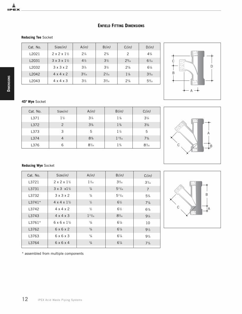
C(in)
37/16
7
53/4
75/8
63/8
91/4
10
91/2
93/4
73/4
Reducing Wye Socket
A
B
C
ENFIELD FITTING DIMENSIONS
Cat. No.
L2021
L2031
L2032
L2042
L2043
Size(in)
2 x 2 x 11/2
3 x 3 x 11/2
3 x 3 x 2
4 x 4 x 2
4 x 4 x 3
A(in)
21/4
41/2
31/4
35/16
31/2
B(in)
23/4
31/2
31/2
21/16
33/16
C(in)
2
29/16
25/8
11/8
23/8
D(in)
43/4
61/16
61/8
33/16
59/16
Cat. No.
L371
L372
L373
L374
L376
Size(in)
11/2
2
3
4
6
A(in)
31/4
35/8
5
83/8
87/16
B(in)
11/8
13/8
11/2
113/16
13/4
C(in)
31/4
35/8
5
73/8
87/16
Reducing Tee Socket
C
B
A
D
45º Wye Socket
A
BC
Cat. No.
L3721
L3731
L3732
L3741*
L3742
L3743
L3761*
L3762
L3763
L3764
Size(in)
2 x 2 x 11/2
3 x 3 x11/2
3 x 3 x 2
4 x 4 x 11/2
4 x 4 x 2
4 x 4 x 3
6 x 6 x 11/2
6 x 6 x 2
6 x 6 x 3
6 x 6 x 4
A(in)
11/16
7/8
7/8
1/2
1/2
113/16
3/8
3/8
3/8
3/8
B(in)
35/16
511/16
511/16
61/2
61/2
85/16
67/8
67/8
67/8
67/8
* assembled from multiple components
DIM
ENSION
SG
ENERAL
INFORM
ATION
13IPEX Acid Waste Piping Systems
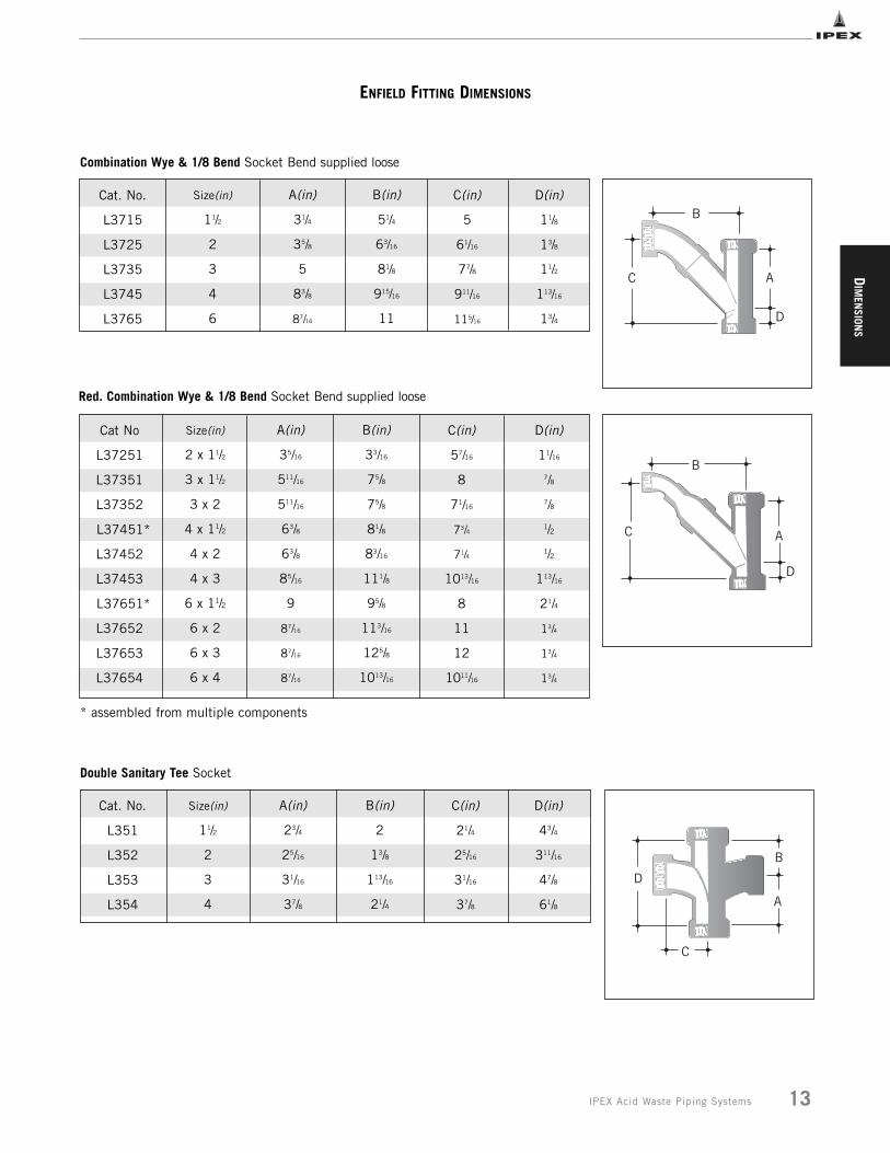
ENFIELD FITTING DIMENSIONS
Cat. No.
L3715
L3725
L3735
L3745
L3765
Size(in)
11/2
2
3
4
6
A(in)
31/4
35/8
5
83/8
87/16
B(in)
51/4
63/16
81/8
915/16
11
C(in)
5
61/16
77/8
911/16
115/16
D(in)
11/8
13/8
11/2
113/16
13/4
Combination Wye & 1/8 Bend Socket Bend supplied loose
C
B
A
D
Cat No
L37251
L37351
L37352
L37451*
L37452
L37453
L37651*
L37652
L37653
L37654
Size(in)
2 x 11/2
3 x 11/2
3 x 2
4 x 11/2
4 x 2
4 x 3
6 x 11/2
6 x 2
6 x 3
6 x 4
Red. Combination Wye & 1/8 Bend Socket Bend supplied loose
C
B
A
D
Double Sanitary Tee Socket
Cat. No.
L351
L352
L353
L354
Size(in)
11/2
2
3
4
A(in)
23/4
25/16
31/16
37/8
B(in)
2
13/8
113/16
21/4
C(in)
21/4
25/16
31/16
37/8
D(in)
43/4
311/16
47/8
61/8
C
B
D
A
A(in)
35/16
511/16
511/16
63/8
63/8
85/16
9
87/16
87/16
87/16
B(in)
33/16
75/8
75/8
81/8
83/16
111/8
95/8
113/16
125/8
1013/16
C(in)
57/16
8
71/16
73/4
71/4
1013/16
8
11
12
1011/16
D(in)
11/16
7/8
7/8
1/2
1/2
113/16
21/4
13/4
13/4
13/4
* assembled from multiple components
DIM
ENSI
ONS
14 IPEX Acid Waste Piping Systems
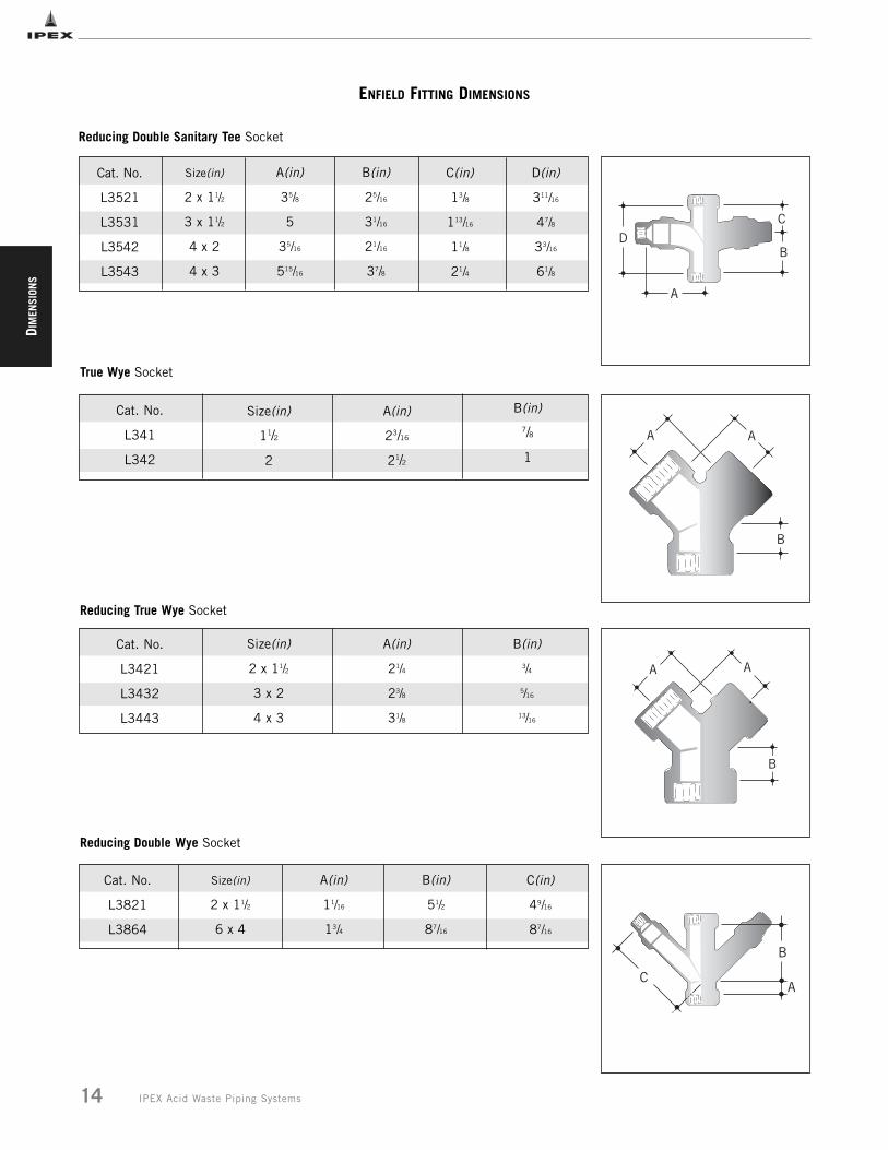
ENFIELD FITTING DIMENSIONS
Cat. No.
L3521
L3531
L3542
L3543
Size(in)
2 x 11/2
3 x 11/2
4 x 2
4 x 3
A(in)
35/8
5
35/16
515/16
B(in)
25/16
31/16
21/16
37/8
C(in)
13/8
113/16
11/8
21/4
D(in)
311/16
47/8
33/16
61/8
Cat. No.
L341
L342
Size(in)
11/2
2
A(in)
23/16
21/2
B(in)7/8
1
Cat. No.
L3421
L3432
L3443
Size(in)
2 x 11/2
3 x 2
4 x 3
A(in)
21/4
23/8
31/8
B(in)
3/4
5/16
13/16
Reducing Double Sanitary Tee Socket
True Wye Socket
Reducing True Wye Socket
Cat. No.
L3821
L3864
Size(in)
2 x 11/2
6 x 4
A(in)
11/16
13/4
B(in)
51/2
87/16
C(in)
49/16
87/16
Reducing Double Wye Socket
C
BD
A
A A
B
A A
B
C
B
A
DIM
ENSION
S
15IPEX Acid Waste Piping Systems
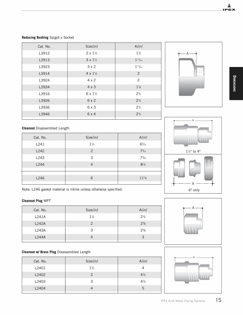
Reducing Bushing Spigot x Socket
Cat. No.
L3912
L3913
L3923
L3914
L3924
L3934
L3916
L3926
L3936
L3946
Size(in)
2 x 11/2
3 x 11/2
3 x 2
4 x 11/2
4 x 2
4 x 3
6 x 11/2
6 x 2
6 x 3
6 x 4
A(in)
11/4
111/16
111/16
2
2
17/8
21/2
21/2
21/2
21/2
A
Cat. No.
L241
L242
L243
L244
L246
Size(in)
11/2
2
3
4
6
A(in)
65/16
75/16
75/16
81/4
115/8
Cleanout Disassembled Length
A
A
6" only
11/2" to 4"
Note: L246 gasket material is nitrile unless otherwise specified.
Cat. No.
L241A
L242A
L243A
L244A
Size(in)
11/2
2
3
4
A(in)
21/4
23/8
23/8
3
Cleanout Plug MPT
Cat. No.
L2401
L2402
L2403
L2404
Size(in)
11/2
2
3
4
A(in)
4
41/2
41/2
5
Cleanout w/ Brass Plug Disassembled Length
A
A
DIM
ENSI
ONS
16 IPEX Acid Waste Piping Systems
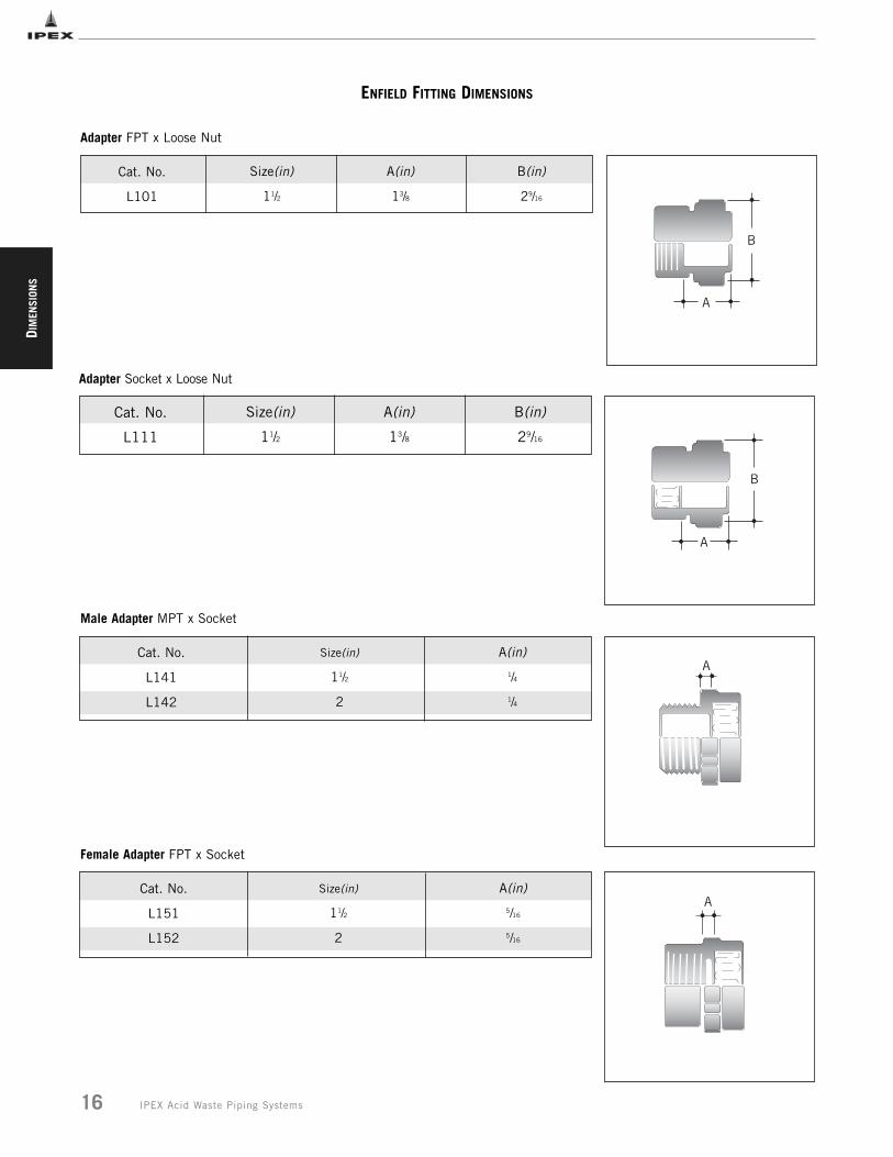
ENFIELD FITTING DIMENSIONS
Cat. No.
L141
L142
Size(in)
11/2
2
A(in)
1/4
1/4
Cat. No.
L151
L152
Size(in)
11/2
2
A(in)
5/16
5/16
Cat. No.
L111
Size(in)
11/2
A(in)
13/8
B(in)
29/16
Adapter Socket x Loose Nut
Male Adapter MPT x Socket
A
B
A
Female Adapter FPT x Socket
A
Cat. No.
L101
Size(in)
11/2
A(in)
13/8
B(in)
29/16
Adapter FPT x Loose Nut
B
A
DIM
ENSION
S
17IPEX Acid Waste Piping Systems
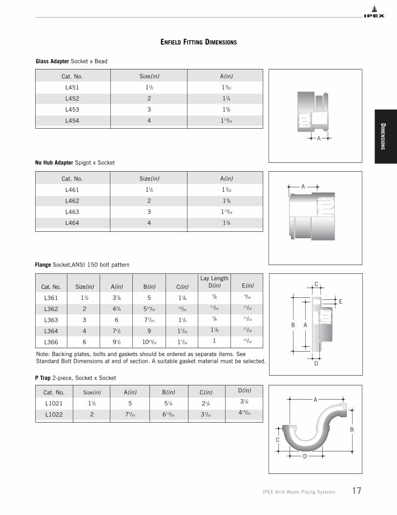
ENFIELD FITTING DIMENSIONS
Cat. No.
L461
L462
L463
L464
Size(in)
11/2
2
3
4
A(in)
17/32
13/8
113/16
13/4
Cat. No.
L361
L362
L363
L364
L366
Size(in)
11/2
2
3
4
6
A(in)
37/8
43/4
6
71/2
91/2
B(in)
5
515/16
77/16
9
1015/16
C(in)
11/8
15/16
11/4
17/16
17/16
D(in)
5/8
11/16
7/8
11/8
1
E(in)
9/16
11/16
11/16
11/16
13/16
Cat. No.
L1021
L1022
Size(in)
11/2
2
A(in)
5
75/16
B(in)
51/4
613/16
C(in)
21/4
37/16
D(in)
31/4
415/16
No Hub Adapter Spigot x Socket
Flange Socket,ANSI 150 bolt pattern
A
C
E
AB
D
C
A
D
B
Note: Backing plates, bolts and gaskets should be ordered as separate items. SeeStandard Bolt Dimensions at end of section. A suitable gasket material must be selected.
Lay Length
Cat. No.
L451
L452
L453
L454
Size(in)
11/2
2
3
4
A(in)
13/32
11/4
15/8
113/16
Glass Adapter Socket x Bead
A
P Trap 2-piece, Socket x Socket
DIM
ENSI
ONS
18 IPEX Acid Waste Piping Systems
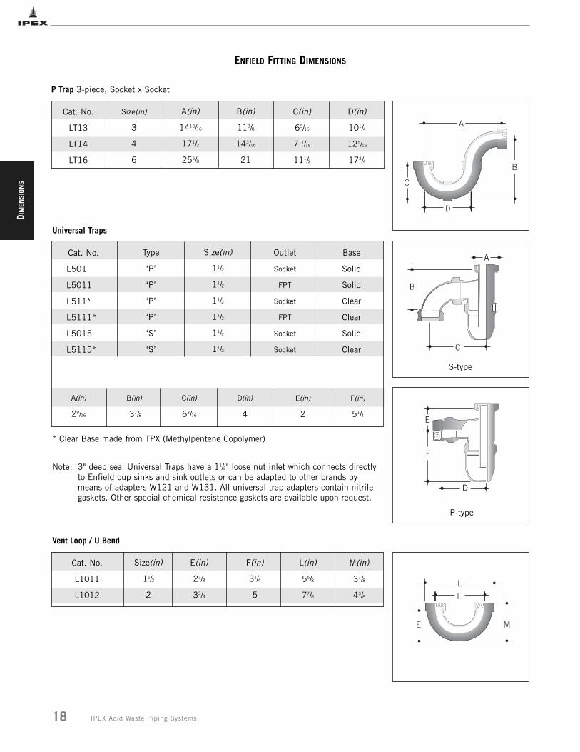
ENFIELD FITTING DIMENSIONS
Cat. No.
L501
L5011
L511*
L5111*
L5015
L5115*
Type
‘P’
‘P’
‘P’
‘P’
‘S’
‘S’
Size(in)
11/2
11/2
11/2
11/2
11/2
11/2
Outlet
Socket
FPT
Socket
FPT
Socket
Socket
Base
Solid
Solid
Clear
Clear
Solid
Clear
A(in)
29/16
B(in)
37/8
C(in)
63/16
D(in)
4
E(in)
2
F(in)
51/4
Note: 3" deep seal Universal Traps have a 11/2" loose nut inlet which connects directly to Enfield cup sinks and sink outlets or can be adapted to other brands by means of adapters W121 and W131. All universal trap adapters contain nitrile gaskets. Other special chemical resistance gaskets are available upon request.
E
F
D
A
B
C
Universal Traps
S-type
P-type
* Clear Base made from TPX (Methylpentene Copolymer)
P Trap 3-piece, Socket x Socket
Cat. No.
LT13
LT14
LT16
Size(in)
3
4
6
A(in)
1413/16
171/2
255/8
B(in)
113/8
143/16
21
C(in)
65/16
711/16
111/2
D(in)
101/4
125/16
173/4
C
A
B
D
Size(in)
11/2
2
E(in)
23/8
33/8
F(in)
31/4
5
L(in)
55/8
77/8
M(in)
31/8
43/8
E
L
M
F
Vent Loop / U Bend
Cat. No.
L1011
L1012
DIM
ENSION
S
19IPEX Acid Waste Piping Systems
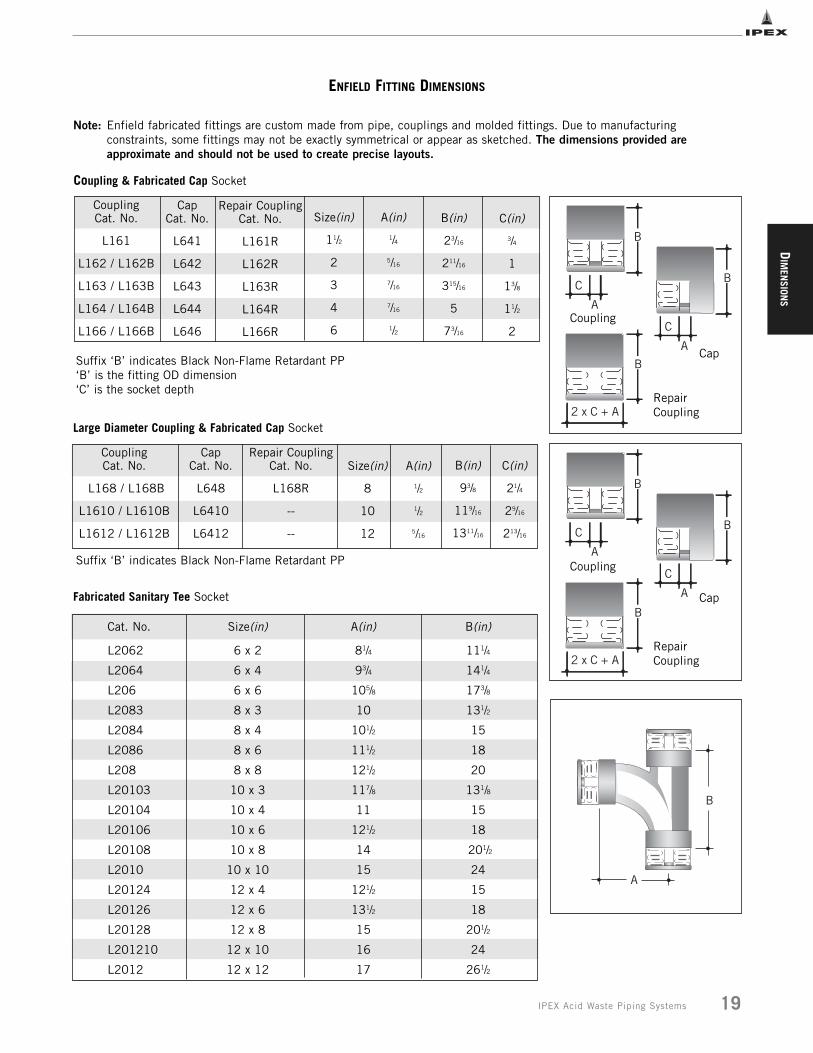
ENFIELD FITTING DIMENSIONS
Cat. No. Size(in) A(in) B(in)
L2062 6 x 2 81/4 111/4
L2064 6 x 4 93/4 141/4
L206 6 x 6 105/8 173/8
L2083 8 x 3 10 131/2
L2084 8 x 4 101/2 15
L2086 8 x 6 111/2 18
L208 8 x 8 121/2 20
L20103 10 x 3 117/8 131/8
L20104 10 x 4 11 15
L20106 10 x 6 121/2 18
L20108 10 x 8 14 201/2
L2010 10 x 10 15 24
L20124 12 x 4 121/2 15
L20126 12 x 6 131/2 18
L20128 12 x 8 15 201/2
L201210 12 x 10 16 24
L2012 12 x 12 17 261/2
B
A
CouplingCat. No.
L168 / L168B
L1610 / L1610B
L1612 / L1612B
CapCat. No.
L648
L6410
L6412
Size(in)
8
10
12
A(in)
1/2
1/2
5/16
B(in)
93/8
119/16
1311/16
Large Diameter Coupling & Fabricated Cap Socket
Fabricated Sanitary Tee Socket
Repair CouplingCat. No.
L168R
--
--
C(in)
21/4
29/16
213/16
CouplingCat. No.
L161
L162 / L162B
L163 / L163B
L164 / L164B
L166 / L166B
Cap Cat. No.
L641
L642
L643
L644
L646
Size(in)
11/2
2
3
4
6
B(in)
23/16
211/16
315/16
5
73/16
C(in)
3/4
1
13/8
11/2
2
A(in)
1/4
5/16
7/16
7/16
1/2
Suffix ‘B’ indicates Black Non-Flame Retardant PP‘B’ is the fitting OD dimension‘C’ is the socket depth
Coupling & Fabricated Cap Socket
B
C
A
B
C
A
Coupling
Cap
Repair CouplingCat. No.
L161R
L162R
L163R
L164R
L166R
RepairCoupling
B
2 x C + A
B
C
A
B
C
A
Coupling
Cap
RepairCoupling
B
2 x C + A
Suffix ‘B’ indicates Black Non-Flame Retardant PP
Note: Enfield fabricated fittings are custom made from pipe, couplings and molded fittings. Due to manufacturing constraints, some fittings may not be exactly symmetrical or appear as sketched. The dimensions provided are approximate and should not be used to create precise layouts.
DIM
ENSI
ONS
20 IPEX Acid Waste Piping Systems
ENFIELD FITTING DIMENSIONS
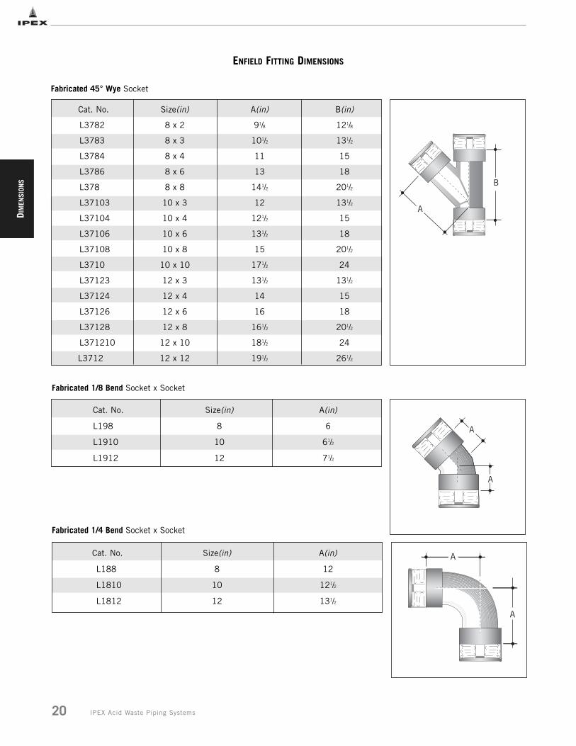
Cat. No. Size(in) A(in)
L198 8 6
L1910 10 61/2
L1912 12 71/2
Cat. No. Size(in) A(in)
L188 8 12
L1810 10 121/2
L1812 12 131/2
A
A
A
A
Fabricated 45° Wye Socket
Cat. No. Size(in) A(in) B(in)
L3782 8 x 2 91/8 121/8
L3783 8 x 3 101/2 131/2
L3784 8 x 4 11 15
L3786 8 x 6 13 18
L378 8 x 8 141/2 201/2
L37103 10 x 3 12 131/2
L37104 10 x 4 121/2 15
L37106 10 x 6 131/2 18
L37108 10 x 8 15 201/2
L3710 10 x 10 171/2 24
L37123 12 x 3 131/2 131/2
L37124 12 x 4 14 15
L37126 12 x 6 16 18
L37128 12 x 8 161/2 201/2
L371210 12 x 10 181/2 24
L3712 12 x 12 191/2 261/2
Fabricated 1/8 Bend Socket x Socket
Fabricated 1/4 Bend Socket x Socket
B
A
DIM
ENSION
S
21IPEX Acid Waste Piping Systems
ENFIELD FITTING DIMENSIONS
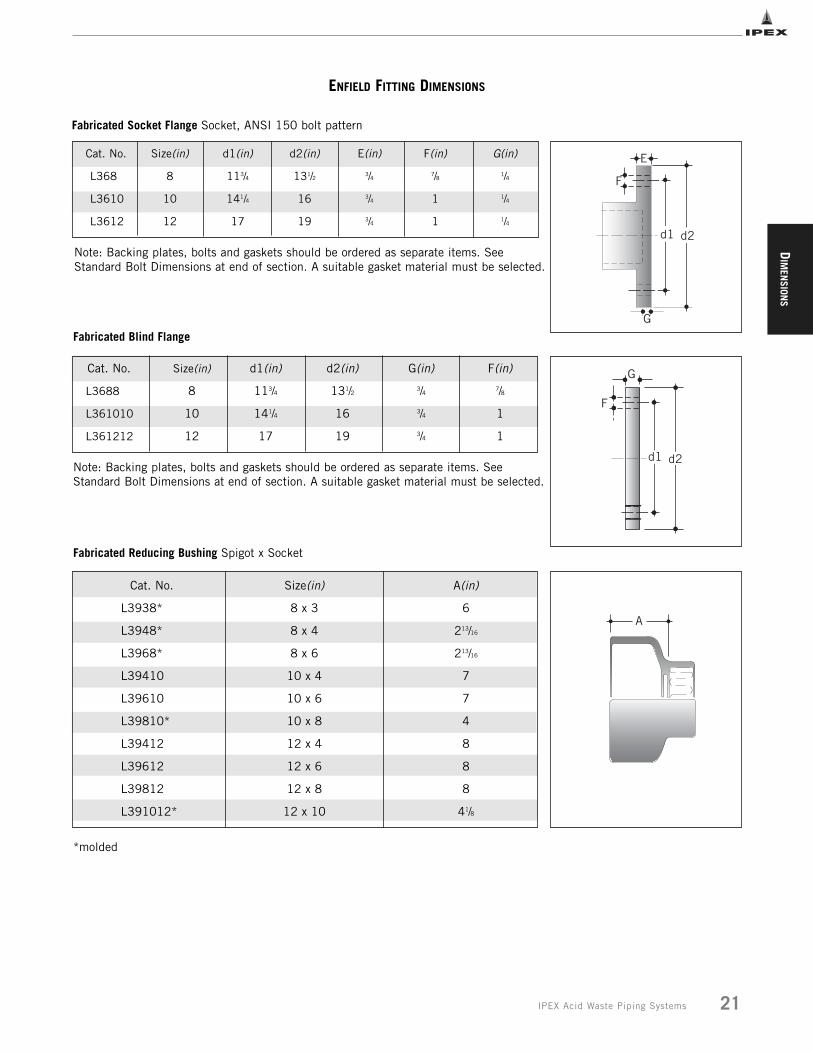
Cat. No. Size(in) d1(in) d2(in) E(in) F(in) G(in)
L368 8 113/4 131/2 3/4 7/8 1/4
L3610 10 141/4 16 3/4 1 1/4
L3612 12 17 19 3/4 1 1/4d1
E
F
G
d2
Fabricated Socket Flange Socket, ANSI 150 bolt pattern
Cat. No. Size(in) d1(in) d2(in) G(in) F(in)
L3688 8 113/4 131/2 3/4 7/8
L361010 10 141/4 16 3/4 1
L361212 12 17 19 3/4 1
d1
G
F
d2
Fabricated Blind Flange
Cat. No. Size(in) A(in)
L3938* 8 x 3 6
L3948* 8 x 4 213/16
L3968* 8 x 6 213/16
L39410 10 x 4 7
L39610 10 x 6 7
L39810* 10 x 8 4
L39412 12 x 4 8
L39612 12 x 6 8
L39812 12 x 8 8
L391012* 12 x 10 41/8
A
Fabricated Reducing Bushing Spigot x Socket
*molded
Note: Backing plates, bolts and gaskets should be ordered as separate items. SeeStandard Bolt Dimensions at end of section. A suitable gasket material must be selected.
Note: Backing plates, bolts and gaskets should be ordered as separate items. SeeStandard Bolt Dimensions at end of section. A suitable gasket material must be selected.
DIM
ENSI
ONS
22 IPEX Acid Waste Piping Systems
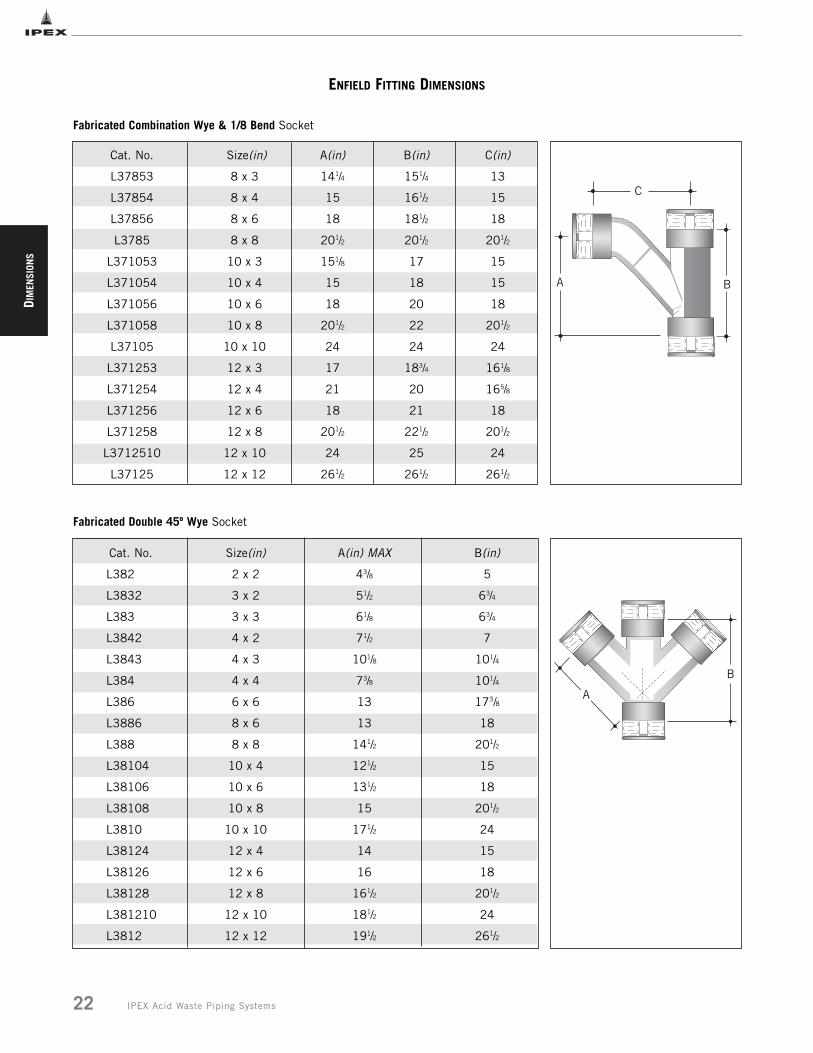
Cat. No. Size(in) A(in) MAX B(in)
L382 2 x 2 43/8 5
L3832 3 x 2 51/2 63/4
L383 3 x 3 61/8 63/4
L3842 4 x 2 71/2 7
L3843 4 x 3 101/8 101/4
L384 4 x 4 73/8 101/4
L386 6 x 6 13 173/8
L3886 8 x 6 13 18
L388 8 x 8 141/2 201/2
L38104 10 x 4 121/2 15
L38106 10 x 6 131/2 18
L38108 10 x 8 15 201/2
L3810 10 x 10 171/2 24
L38124 12 x 4 14 15
L38126 12 x 6 16 18
L38128 12 x 8 161/2 201/2
L381210 12 x 10 181/2 24
L3812 12 x 12 191/2 261/2
B
A
Fabricated Double 45º Wye Socket
ENFIELD FITTING DIMENSIONS
Cat. No. Size(in) A(in) B(in) C(in)
L37853 8 x 3 141/4 151/4 13
L37854 8 x 4 15 161/2 15
L37856 8 x 6 18 181/2 18
L3785 8 x 8 201/2 201/2 201/2
L371053 10 x 3 151/8 17 15
L371054 10 x 4 15 18 15
L371056 10 x 6 18 20 18
L371058 10 x 8 201/2 22 201/2
L37105 10 x 10 24 24 24
L371253 12 x 3 17 183/4 161/8
L371254 12 x 4 21 20 165/8
L371256 12 x 6 18 21 18
L371258 12 x 8 201/2 221/2 201/2
L3712510 12 x 10 24 25 24
L37125 12 x 12 261/2 261/2 261/2
A
C
B
Fabricated Combination Wye & 1/8 Bend Socket
ENFIELD FITTING DIMENSIONS
DIM
ENSION
S
23IPEX Acid Waste Piping Systems
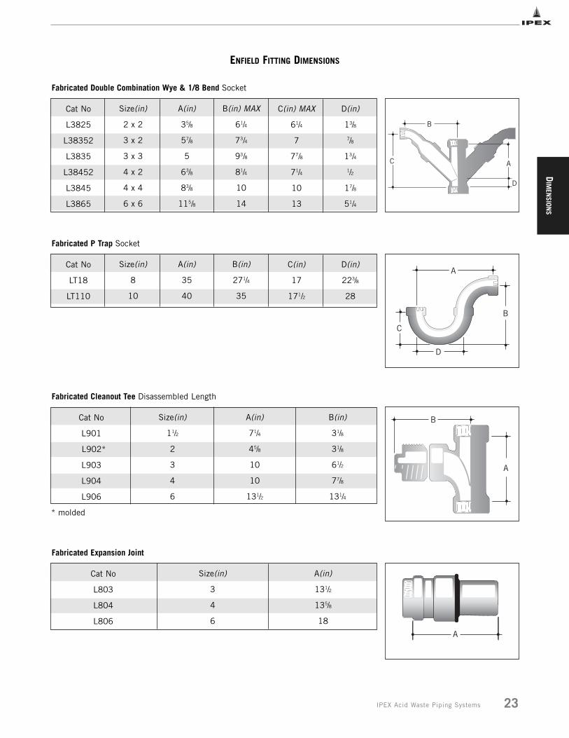
Cat No
L3825
L38352
L3835
L38452
L3845
L3865
Size(in)
2 x 2
3 x 2
3 x 3
4 x 2
4 x 4
6 x 6
A(in)
35/8
57/8
5
63/8
83/8
115/8
B(in) MAX
61/4
73/4
93/8
81/4
10
14
C(in) MAX
61/4
7
77/8
71/4
10
13
D(in)
13/8
7/8
13/4
1/2
17/8
51/4
Fabricated Double Combination Wye & 1/8 Bend Socket
C
B
A
D
Cat No
LT18
LT110
Size(in)
8
10
A(in)
35
40
B(in)
271/4
35
C(in)
17
171/2
D(in)
223/8
28
Fabricated P Trap Socket
C
A
D
B
Cat No
L901
L902*
L903
L904
L906
Size(in)
11/2
2
3
4
6
A(in)
71/4
45/8
10
10
131/2
B(in)
31/8
31/8
61/2
77/8
131/4
Fabricated Cleanout Tee Disassembled Length
C
A
B
Cat No
L803
L804
L806
Size(in)
3
4
6
A(in)
131/2
135/8
18
Fabricated Expansion Joint
A
* molded
DIM
ENSI
ONS
24 IPEX Acid Waste Piping Systems
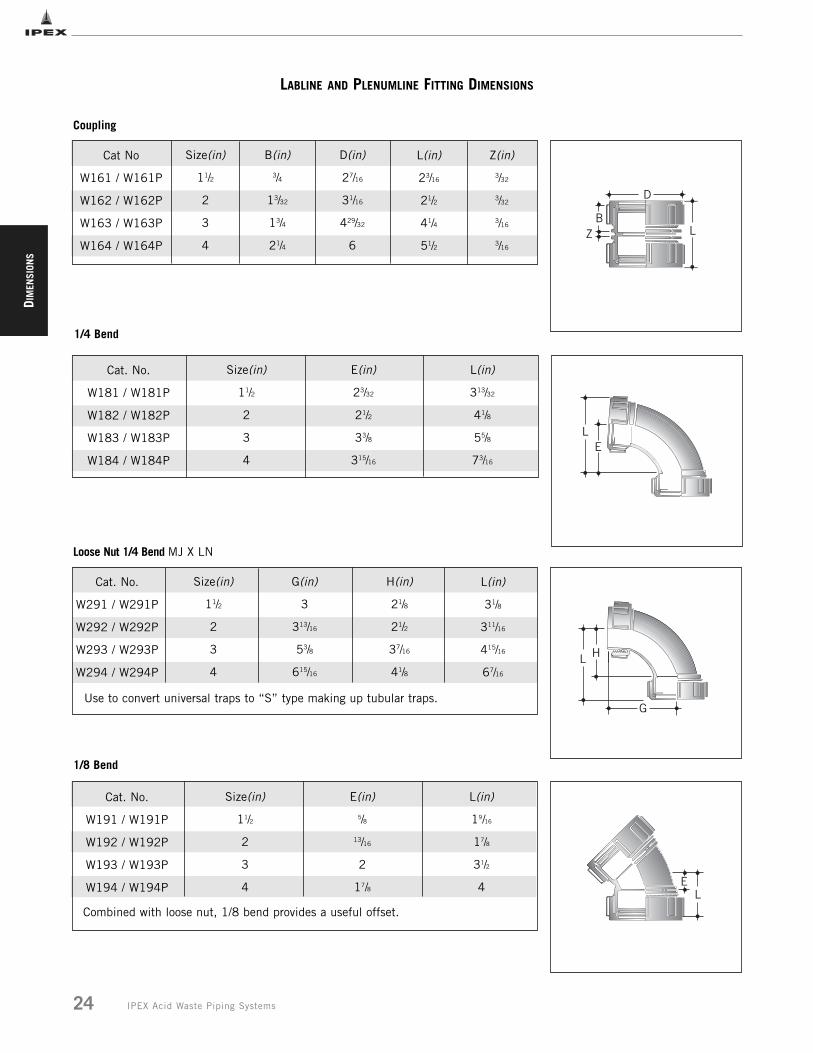
LABLINE AND PLENUMLINE FITTING DIMENSIONS
Size(in)
11/2
2
3
4
B(in)
3/4
13/32
13/4
21/4
D(in)
27/16
31/16
429/32
6
L(in)
23/16
21/2
41/4
51/2
Z(in)
3/32
3/32
3/16
3/16
Cat. No.
W181 / W181P
W182 / W182P
W183 / W183P
W184 / W184P
Size(in)
11/2
2
3
4
E(in)
23/32
21/2
33/8
315/16
L(in)
313/32
41/8
55/8
73/16
Cat. No.
W291 / W291P
W292 / W292P
W293 / W293P
W294 / W294P
Size(in)
11/2
2
3
4
G(in)
3
313/16
53/8
615/16
H(in)
21/8
21/2
37/16
41/8
L(in)
31/8
311/16
415/16
67/16
Cat. No.
W191 / W191P
W192 / W192P
W193 / W193P
W194 / W194P
Size(in)
11/2
2
3
4
E(in)
5/8
13/16
2
17/8
L(in)
19/16
17/8
31/2
4
Combined with loose nut, 1/8 bend provides a useful offset.
LE
LB
D
Z
Use to convert universal traps to “S” type making up tubular traps.
L H
G
Coupling
1/4 Bend
Loose Nut 1/4 Bend MJ X LN
1/8 Bend
LE
Cat No
W161 / W161P
W162 / W162P
W163 / W163P
W164 / W164P

DIM
ENSION
S
25IPEX Acid Waste Piping Systems
Size(in)
11/2
2
3
4
G(in)
25/16
21/2
31/4
37/8
H(in)
11/2
23/16
19/16
3
E(in)
313/16
41/2
43/4
615/16
Size(in)
2 x 11/2
3 x 11/2
3 x 2
4 x 11/2
4 x 2
4 x 3
A(in)
49/16
47/8
6
615/16
615/16
615/16
B(in)
21/2
51/2
313/32
43/4
73/8
65/8
C(in)
21/2
33/8
313/32
41/8
37/8
37/8
Size(in)
11/2
2
3
4
A(in)
25/16
21/2
31/4
37/8
B(in)
11/2
23/16
19/16
3
C(in)
313/16
41/2
43/4
615/16
H
G
M
E L
G
B
AC
C
A
A B
L(in)
6
7
9
121/16
M(in)
41/4
55/16
713/16
10
Sanitary Tee
Reducing Sanitary Tee
Cleanout Tee
LABLINE AND PLENUMLINE FITTING DIMENSIONS
Cat. No.
W211 / W211P
W212 / W212P
W213 / W213P
W214 / W214P
Size(in)
11/2
2
3
4
G(in)
19/16
17/8
4
41/2
H(in)
5/8
11/16
2
13/4
L(in)
13/8
111/16
31/2
4L
G
H
When used with W151 female adapter and screwed directly to sink, outlet provides acompact assembly for turning drainline back to wall.
Loose Nut 1/8 Bend MJ X LN
Cat. No.
W201 / W201P
W202 / W202P
W203 / W203P
W204 / W204P
Cat. No.
W2021 / W2021P
W2031 / W2031P
W2032 / W2032P
W2041
W2042 / W2042P
W2043 / W2043P
Cat. No.
W2015 / W2015P
W2025 / W2025P
W2035 / W2035P
W2045 / W2045P
DIM
ENSI
ONS
26 IPEX Acid Waste Piping Systems
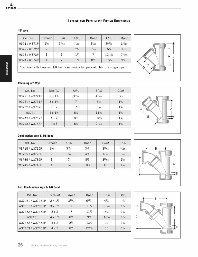
LABLINE AND PLENUMLINE FITTING DIMENSIONS
Size(in)
11/2
2
3
4
E(in)
213/16
3
6
7
F(in)
5/16
11/16
13/4
13/4
G(in)
37/16
39/16
7
81/2
Size(in)
2 x 11/2
3 x 11/2
3 x 2
4 x 11/2
4 x 2
4 x 3
A(in)
311/16
7
7
81/2
81/2
81/2
B(in)
413/16
81/2
81/2
111/8
105/16
911/16
C(in)
11/16
13/4
13/4
13/4
13/4
13/4
A
CB
G LM
E FCombined with loose nut 1/8 bend can provide two parallel inlets to a single pipe.
L(in)
513/16
65/8
1211/16
153/4
M(in)
313/16
41/2
719/32
95/16
45º Wye
Reducing 45º Wye
Size(in)
11/2
2
3
4
A(in)
37/16
35/8
7
81/2
B(in)
35/8
41/4
81/2
101/4
C(in)
311/16
41/16
813/32
10
D(in)
21/64
11/16
13/4
13/4 CA
B
D
Combination Wye & 1/8 Bend
Size(in)
2 x 11/2
3 x 11/2
3 x 2
4 x 11/2
4 x 2
4 x 3
A(in)
319/32
7
7
81/2
81/2
81/2
B(in)
613/64
113/8
113/8
91/2
133/8
1219/32
C(in)
45/32
813/32
81/2
103/8
10
10
D(in)
11/16
13/4
13/4
13/4
13/4
13/4
C
B
A
D
Red. Combination Wye & 1/8 Bend
Cat. No.
W371 / W371P
W372 / W372P
W373 / W373P
W374 / W374P
Cat. No.
W3721 / W3721P
W3731 / W3731P
W3732 / W3732P
W3741
W3742 / W3742P
W3743 / W3743P
Cat. No.
W3715 / W3715P
W3725 / W3725P
W3735 / W3735P
W3745 / W3745P
Cat. No.
W37251 / W37251P
W37351 / W37351P
W37352 / W37352P
W37451
W37452 / W37452P
W37453 / W37453P
DIM
ENSION
S
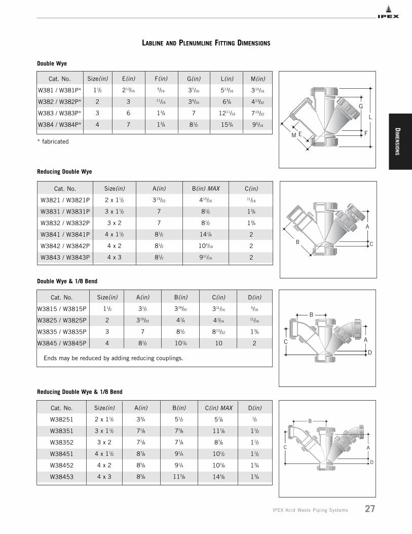
27IPEX Acid Waste Piping Systems
LABLINE AND PLENUMLINE FITTING DIMENSIONS
Size(in)
11/2
2
3
4
E(in)
213/16
3
6
7
F(in)
5/16
11/16
13/4
13/4
L(in)
513/16
63/4
1211/16
153/4
M(in)
315/16
413/32
719/32
95/16
Size(in)
2 x 11/2
3 x 11/2
3 x 2
4 x 11/2
4 x 2
4 x 3
A(in)
319/32
7
7
81/2
81/2
81/2
B(in) MAX
413/16
81/2
81/2
141/4
105/16
911/16
C(in)
11/16
13/4
13/4
2
2
2
Size(in)
11/2
2
3
4
A(in)
31/2
319/32
7
81/2
B(in)
319/32
41/4
81/2
101/4
C(in)
311/16
41/16
813/32
10
D(in)
5/16
11/16
13/4
2
Ends may be reduced by adding reducing couplings.
M E
G
L
F
A
CB
C
B
A
D
G(in)
37/16
39/16
7
81/2
Double Wye
Reducing Double Wye
Double Wye & 1/8 Bend
Cat. No.
W381 / W381P*
W382 / W382P*
W383 / W383P*
W384 / W384P*
Cat. No.
W3821 / W3821P
W3831 / W3831P
W3832 / W3832P
W3841 / W3841P
W3842 / W3842P
W3843 / W3843P
Cat. No.
W3815 / W3815P
W3825 / W3825P
W3835 / W3835P
W3845 / W3845P
Size(in)
2 x 11/2
3 x 11/2
3 x 2
4 x 11/2
4 x 2
4 x 3
A(in)
33/4
71/8
71/8
87/8
85/8
85/8
B(in)
51/2
75/8
77/8
91/4
91/4
115/8
C(in) MAX
57/8
111/8
87/8
101/2
103/8
145/8
D(in)
1/2
11/2
11/2
11/2
13/4
13/4
C
B
A
D
Reducing Double Wye & 1/8 Bend
Cat. No.
W38251
W38351
W38352
W38451
W38452
W38453
* fabricated
DIM
ENSI
ONS
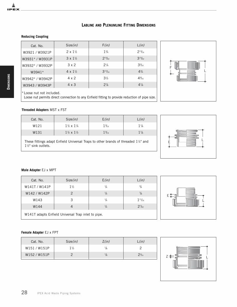
Cat. No.
W151 / W151P
W152 / W151P
Size(in)
11/2
2
Z(in)
1/8
1/8
L(in)
2
25/16 Z L
Female Adapter EJ x FPT
LABLINE AND PLENUMLINE FITTING DIMENSIONS
Size(in)
2 x 11/2
3 x 11/2
3 x 2
4 x 11/2
4 x 2
4 x 3
F(in)
13/4
215/32
21/4
313/16
31/2
27/8
L(in)
213/16
315/32
35/16
43/4
49/16
47/8
*Loose nut not included.Loose nut permits direct connection to any Enfield fitting to provide reduction of pipe size.
Cat. No.
W121
W131
Size(in)
11/2 x 11/4
11/2 x 11/2
E(in)
13/16
13/16
L(in)
17/8
17/8
Size(in)
11/2
2
3
4
E(in)
1/4
1/4
1/4
1/4
L(in)
3/4
7/8
111/16
27/32
W141T adapts Enfield Universal Trap inlet to pipe.
LE
LE
LF
These fittings adapt Enfield Universal Traps to other brands of threaded 11/4" and11/2" sink outlets.
Reducing Coupling
Male Adapter EJ x MPT
Threaded Adapters MST x FST
Cat. No.
W3921 / W3921P
W3931* / W3931P
W3932* / W3932P
W3941*
W3942* / W3942P
W3943 / W3943P
Cat. No.
W141T / W141P
W142 / W142P
W143
W144
28 IPEX Acid Waste Piping Systems
DIM
ENSION
S
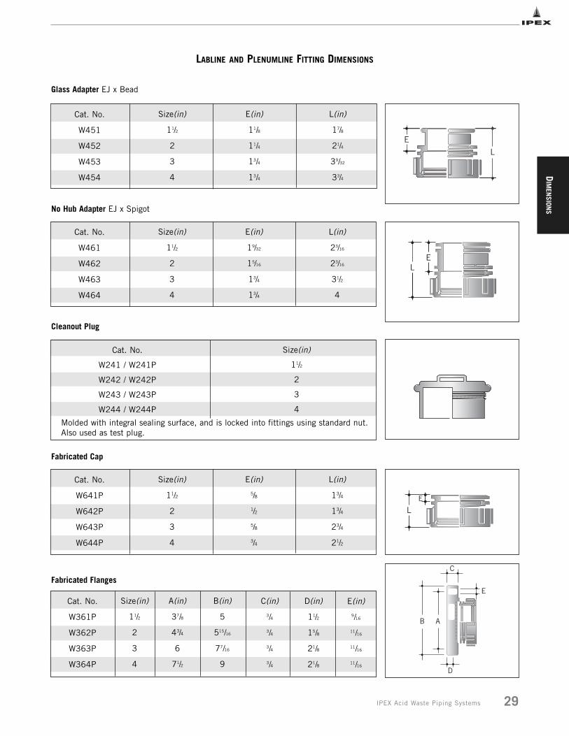
Cat. No.
W461
W462
W463
W464
Size(in)
11/2
2
3
4
E(in)
19/32
15/16
13/4
13/4
L(in)
23/16
23/16
31/2
4
Cat. No.
W241 / W241P
W242 / W242P
W243 / W243P
W244 / W244P
Size(in)
11/2
2
3
4
Molded with integral sealing surface, and is locked into fittings using standard nut.Also used as test plug.
LE
No Hub Adapter EJ x Spigot
Cleanout Plug
LABLINE AND PLENUMLINE FITTING DIMENSIONS
Cat. No.
W451
W452
W453
W454
Size(in)
11/2
2
3
4
E(in)
11/8
11/4
13/4
13/4
L(in)
17/8
21/4
39/32
33/4
E
L
Glass Adapter EJ x Bead
Cat. No.
W641P
W642P
W643P
W644P
Size(in)
11/2
2
3
4
E(in)
5/8
1/2
5/8
3/4
L(in)
13/4
13/4
23/4
21/2
LE
Fabricated Cap
Size(in)
11/2
2
3
4
A(in)
37/8
43/4
6
71/2
B(in)
5
515/16
77/16
9
D(in)
11/2
15/8
21/8
21/8
E(in)
9/16
11/16
11/16
11/16
C
E
AB
D
C(in)
3/4
3/4
3/4
3/4
Fabricated Flanges
Cat. No.
W361P
W362P
W363P
W364P
29IPEX Acid Waste Piping Systems
DIM
ENSI
ONS
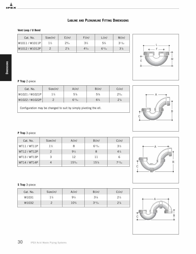
30 IPEX Acid Waste Piping Systems
Size(in)
11/2
2
A(in)
57/8
615/16
B(in)
53/8
63/4
C(in)
29/16
27/8
Configuration may be changed to suit by simply pivoting the ell.
Cat. No.
WT11 / WT11P
WT12 / WT12P
WT13 / WT13P
WT14 / WT14P
Size(in)
11/2
2
3
4
A(in)
8
91/4
12
159/16
B(in)
613/16
8
11
157/8
C(in)
31/2
41/4
6
713/16
A
B
C
C
A
B
LABLINE AND PLENUMLINE FITTING DIMENSIONS
Size(in)
11/2
2
E(in)
29/16
27/8
F(in)
31/2
43/16
L(in)
53/4
613/16
M(in)
311/32
37/8
ME
L
F
Vent Loop / U Bend
P Trap 2-piece
P Trap 3-piece
Size(in)
11/2
2
A(in)
91/4
103/4
B(in)
31/8
313/16
C(in)
21/2
27/8
C B
A
S Trap 3-piece
Cat. No.
W1011 / W1011P
W1012 / W1012P
Cat. No.
W1021 / W1021P
W1022 / W1022P
Cat. No.
W1031
W1032
DIM
ENSION
S
31IPEX Acid Waste Piping Systems
A
B
C
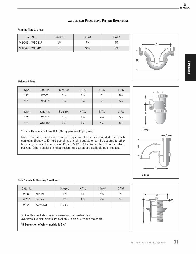
LABLINE AND PLENUMLINE FITTING DIMENSIONS
Cat. No.
W1041 / W1041P
W1042 / W1042P
Size(in)
11/2
2
A(in)
77/8
97/64
B(in)
53/8
63/4
Cat. No.
W501
W511*
Cat. No.
W5015
W5115*
Size(in)
11/2
11/2
Size (in)
11/2
11/2
D(in)
27/8
27/8
A(in)
11/2
11/2
E(in)
2
2
B(in)
45/8
45/8
F(in)
51/4
51/4
C(in)
51/2
51/2
Type
“P”
“P”
Type
“S”
“S”
Note: Three inch deep seal Universal Traps have 11/2" female threaded inlet whichconnects directly to Enfield cup sinks and sink outlets or can be adapted to otherbrands by means of adapters W121 and W131. All universal traps contain nitrilegaskets. Other special chemical resistance gaskets are available upon request.
B
A
Cat. No.
W301
W311
W321
Size(in)
11/2
11/2
11/2 x 7
A(in)
33/8
27/8
-
*B(in)
43/8
43/8
-
C(in)
3/32
3/32
-
Sink outlets include integral strainer and removable plug. Overflows like sink outlets are available in black or white materials.
*B Dimension of white models is 31/2".
(outlet)
(outlet)
(overflow)
A
C
B
Running Trap 3-piece
Universal Trap
Sink Outlets & Standing Overflows
S-type
D
F
E
P-type* Clear Base made from TPX (Methylpentene Copolymer)
DIM
ENSI
ONS
32 IPEX Acid Waste Piping Systems
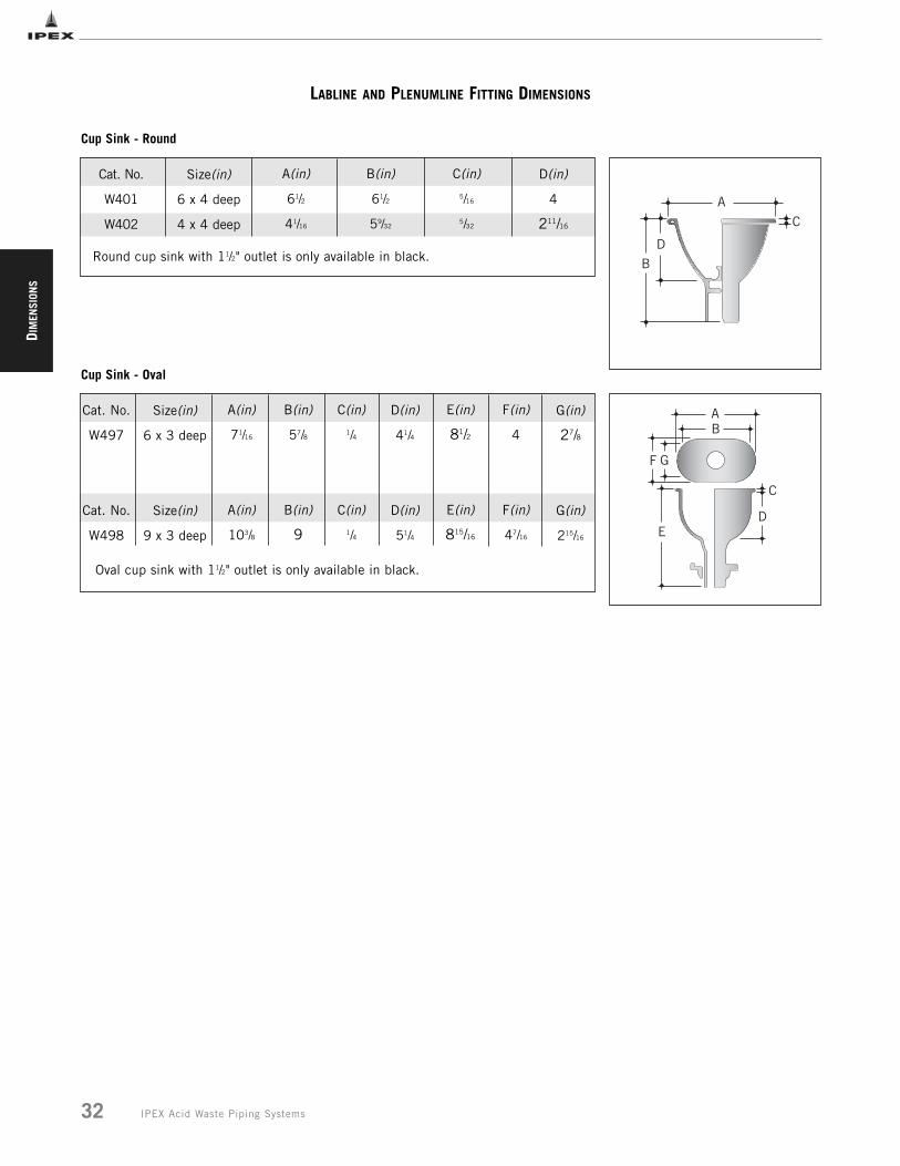
LABLINE AND PLENUMLINE FITTING DIMENSIONS
Cat. No.
W401
W402
A(in)
61/2
41/16
B(in)
61/2
59/32
C(in)
5/16
5/32
D(in)
4
211/16
Round cup sink with 11/2" outlet is only available in black.
Size(in)
6 x 4 deep
4 x 4 deep
Cat. No.
W497
Cat. No.
W498
A(in)
71/16
A(in)
103/8
B(in)
57/8
B(in)
9
C(in)
1/4
C(in)
1/4
D(in)
41/4
D(in)
51/4
Size(in)
6 x 3 deep
Size(in)
9 x 3 deep
Cup Sink - Round
A
C
DB
Cup Sink - Oval
AB
C
F G
ED
E(in)
81/2
E(in)
815/16
F(in)
4
F(in)
47/16
G(in)
27/8
G(in)
215/16
Oval cup sink with 11/2" outlet is only available in black.
DIM
ENSION
S
33IPEX Acid Waste Piping Systems
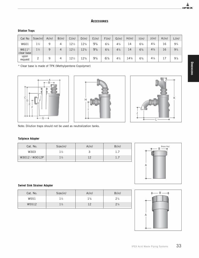
ACCESSORIES
Cat No
W601
W611*clear base
uponrequest
Size(in)
11/2
11/2
2
A(in)
9
9
9
B(in)
4
4
4
C(in)
121/2
121/2
121/2
D(in)
123/8
123/8
123/8
Dilution Traps
E(in)
95/8
95/8
95/8
F(in)
65/8
65/8
65/8
G(in)
43/4
43/4
43/4
H(in)
14
14
143/8
I(in)
65/8
65/8
65/8
J(in)
43/8
43/8
41/8
K(in)
16
16
17
L(in)
93/4
93/4
97/8
K
L
J
AB
CD
EF
G
I
H
Note: Dilution traps should not be used as neutralization tanks.
* Clear base is made of TPX (Methylpentene Copolymer)
A
BBrass NutCat. No. Size(in) A(in) B(in)
W303 11/2 3 1.7
W3012 / W3012P 11/2 12 1.7
Tailpiece Adapter
A
BCat. No. Size(in) A(in) B(in)
W551 11/2 15/8 21/4
W5512 11/2 12 21/4
Swivel Sink Strainer Adapter
DIM
ENSI
ONS
34 IPEX Acid Waste Piping Systems
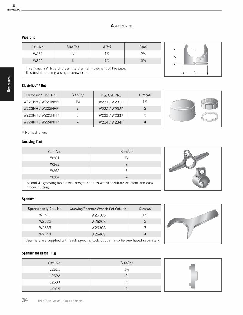
ACCESSORIES
Grooving/Spanner Wrench Set Cat. No.
W261CS
W262CS
W263CS
W264CS
Size(in)
11/2
2
3
4
Spanners are supplied with each grooving tool, but can also be purchased separately.
Cat. No.
W261
W262
W263
W264
Size(in)
11/2
2
3
4
3" and 4" grooving tools have integral handles which facilitate efficient and easygroove cutting.
Grooving Tool
Spanner
Spanner only Cat. No.
W2611
W2622
W2633
W2644
Size(in)
11/2
2
3
4
Nut Cat. No.
W231 / W231P
W232 / W232P
W233 / W233P
W234 / W234P
Size(in)
11/2
2
3
4
ElastoliveTM / Nut
* No-heat olive.
Cat. No.
W251
W252
Size(in)
11/2
2
A(in)
15/8
13/4
B(in)
23/8
33/4
This “snap-in” type clip permits thermal movement of the pipe. It is installed using a single screw or bolt. B
A
Pipe Clip
Elastolive* Cat. No.
W221NH / W221NHP
W222NH / W222NHP
W223NH / W223NHP
W224NH / W224NHP
Cat. No.
L2611
L2622
L2633
L2644
Size(in)
11/2
2
3
4
Spanner for Brass Plug
DIM
ENSION
S
35IPEX Acid Waste Piping Systems
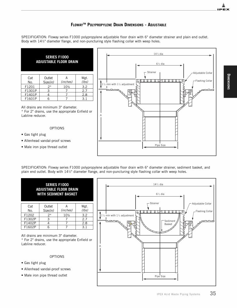
FLOWAYTM POLYPROPYLENE DRAIN DIMENSIONS - ADJUSTABLE
CatNo.
F1201F1301PF1401PF1601P
OutletSize(in)
2*346
A(inches)
105/8777
Wgt.(lbs)3.22.72.83.1
All drains are minimum 3" diameter. * For 2" drains, use the appropriate Enfield orLabline reducer.
OPTIONS
• Gas tight plug
• Allenhead vandal-proof screws
• Male iron pipe thread outlet
CatNo.
F1202F1302PF1402PF1602P
OutletSize(in)
2*346
A(inches)
105/8777
Wgt.(lbs)3.22.72.83.1
All drains are minimum 3" diameter. * For 2" drains, use the appropriate Enfield orLabline reducer.
OPTIONS
• Gas tight plug
• Allenhead vandal-proof screws
• Male iron pipe thread outlet
SPECIFICATION: Floway series F1000 polypropylene adjustable floor drain with 6" diameter strainer and plain end outlet.Body with 141/2" diameter flange, and non-puncturing style flashing collar with weep holes.
SERIES F1000ADJUSTABLE FLOOR DRAIN
SPECIFICATION: Floway series F1000 polypropylene adjustable floor drain with 6" diameter strainer, sediment basket, andplain end outlet. Body with 141/2" diameter flange, and non-puncturing style flashing collar with weep holes.
SERIES F1000ADJUSTABLE FLOOR DRAIN WITH SEDIMENT BASKET

DIM
ENSI
ONS
36 IPEX Acid Waste Piping Systems
FLOWAYTM POLYPROPYLENE DRAIN DIMENSIONS - ADJUSTABLE
CatNo.
F1203F1303PF1403PF1603P
OutletSize(in)
2* 346
A(inches)
105/8777
Wgt.(lbs)3.22.72.83.1
All drains are minimum 3" diameter. * For 2" drains, use the appropriate Enfield orLabline reducer.
OPTIONS
• Gas tight plug
• Allenhead vandal-proof screws
• Male iron pipe thread outlet
CatNo.
F1204F1304PF1404PF1604P
OutletSize(in)
2*346
A(inches)
105/8777
Wgt.(lbs)3.22.72.83.1
All drains are minimum 3" diameter. * For 2" drains, use the appropriate Enfield orLabline reducer.
OPTIONS
• Gas tight plug
• Allenhead vandal-proof screws
• Male iron pipe thread outlet
SPECIFICATION: Floway series F1000 polypropylene adjustable floor drain with 6" diameter strainer, sediment basket, 6" diameterfunnel and plain end outlet. Body with 141/2" diameter flange, and non-puncturing style flashing collar with weep holes.
SERIES F1000ADJUSTABLE FLOOR DRAIN WITH SEDIMENT BASKET AND 6" ROUND FUNNEL
SPECIFICATION: Floway series F1000 polypropylene adjustable floor drain with 6" diameter strainer, 6" diameter funnel andplain end outlet. Body with 141/2" diameter flange, and non-puncturing style flashing collar with weep holes.
SERIES F1000ADJUSTABLE FLOOR DRAIN WITH
6" ROUND FUNNEL

DIM
ENSION
S
37IPEX Acid Waste Piping Systems
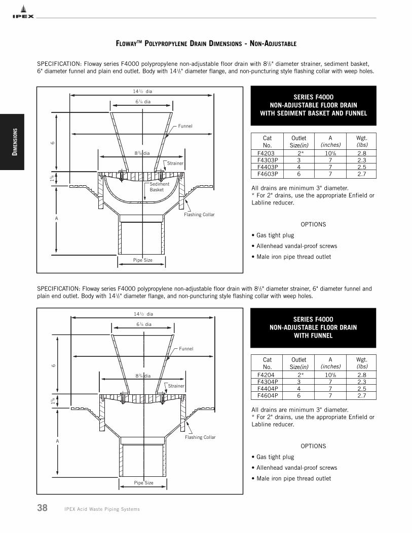
FLOWAYTM POLYPROPYLENE DRAIN DIMENSIONS - NON-ADJUSTABLE
CatNo.
F4201F4301PF4401PF4601P
OutletSize(in)
2*346
A(inches)
105/8777
Wgt.(lbs)2.82.32.52.7
All drains are minimum 3" diameter. * For 2" drains, use the appropriate Enfield orLabline reducer.
OPTIONS
• Gas tight plug
• Allenhead vandal-proof screws
• Male iron pipe thread outlet
CatNo.
F4202F4302PF4402PF4602P
OutletSize(in)
2*346
A(inches)
105/8777
Wgt.(lbs)2.82.32.52.7
All drains are minimum 3" diameter. * For 2" drains, use the appropriate Enfield orLabline reducer.
OPTIONS
• Gas tight plug
• Allenhead vandal-proof screws
• Male iron pipe thread outlet
SPECIFICATION: Floway series F4000 polypropylene non-adjustable floor drain with 81/2" diameter strainer and plain endoutlet. Body with 141/2" diameter flange, and non-puncturing style flashing collar with weep holes.
SERIES F4000NON-ADJUSTABLE
FLOOR DRAIN
SPECIFICATION: Floway series F4000 polypropylene non-adjustable floor drain with 81/2" diameter strainer, sediment basket, andplain end outlet. Body with 141/2" diameter flange, and non-puncturing style flashing collar with weep holes.
SERIES F4000NON-ADJUSTABLE FLOOR DRAIN
WITH SEDIMENT BASKET
DIM
ENSI
ONS
38 IPEX Acid Waste Piping Systems
FLOWAYTM POLYPROPYLENE DRAIN DIMENSIONS - NON-ADJUSTABLE
All drains are minimum 3" diameter. * For 2" drains, use the appropriate Enfield orLabline reducer.
OPTIONS
• Gas tight plug
• Allenhead vandal-proof screws
• Male iron pipe thread outlet
CatNo.
F4203F4303PF4403PF4603P
OutletSize(in)
2*346
A(inches)
105/8777
Wgt.(lbs)2.82.32.52.7
All drains are minimum 3" diameter. * For 2" drains, use the appropriate Enfield orLabline reducer.
OPTIONS
• Gas tight plug
• Allenhead vandal-proof screws
• Male iron pipe thread outlet
CatNo.
F4204F4304PF4404PF4604P
OutletSize(in)
2*346
A(inches)
105/8777
Wgt.(lbs)2.82.32.52.7
SPECIFICATION: Floway series F4000 polypropylene non-adjustable floor drain with 81/2" diameter strainer, sediment basket,6" diameter funnel and plain end outlet. Body with 141/2" diameter flange, and non-puncturing style flashing collar with weep holes.
SERIES F4000NON-ADJUSTABLE FLOOR DRAIN
WITH SEDIMENT BASKET AND FUNNEL
SPECIFICATION: Floway series F4000 polypropylene non-adjustable floor drain with 81/2" diameter strainer, 6" diameter funnel andplain end outlet. Body with 141/2" diameter flange, and non-puncturing style flashing collar with weep holes.
SERIES F4000NON-ADJUSTABLE FLOOR DRAIN
WITH FUNNEL
14
DIM
ENSION
S
39IPEX Acid Waste Piping Systems
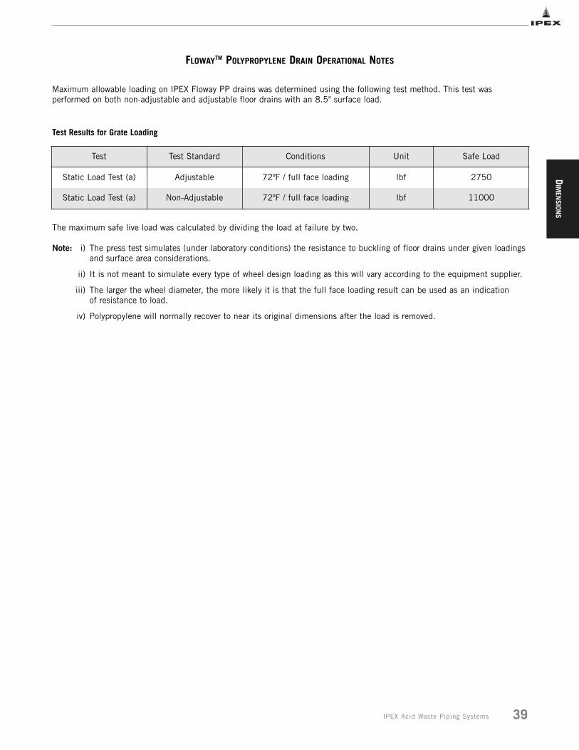
FLOWAYTM POLYPROPYLENE DRAIN OPERATIONAL NOTES
Maximum allowable loading on IPEX Floway PP drains was determined using the following test method. This test wasperformed on both non-adjustable and adjustable floor drains with an 8.5" surface load.
Test Results for Grate Loading
Test Test Standard Conditions Unit Safe Load
Static Load Test (a) Adjustable 72ºF / full face loading lbf 2750
Static Load Test (a) Non-Adjustable 72ºF / full face loading lbf 11000
The maximum safe live load was calculated by dividing the load at failure by two.
Note: i) The press test simulates (under laboratory conditions) the resistance to buckling of floor drains under given loadingsand surface area considerations.
ii) It is not meant to simulate every type of wheel design loading as this will vary according to the equipment supplier.
iii) The larger the wheel diameter, the more likely it is that the full face loading result can be used as an indication of resistance to load.
iv) Polypropylene will normally recover to near its original dimensions after the load is removed.
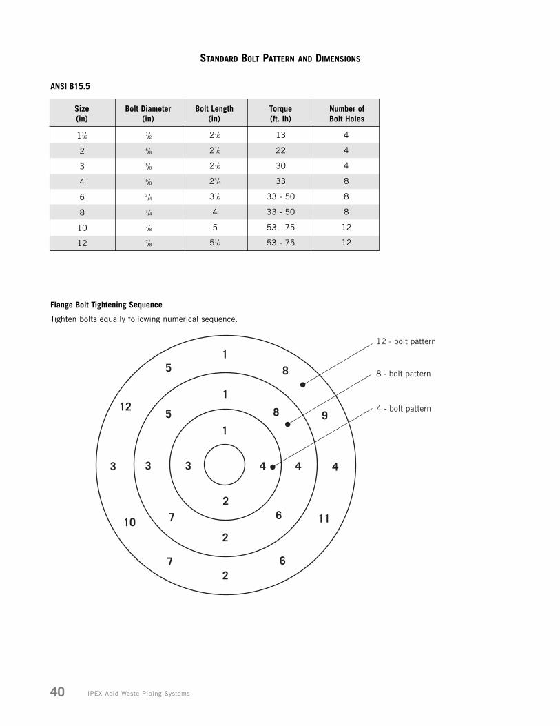
IPEX Acid Waste Piping Systems40
STANDARD BOLT PATTERN AND DIMENSIONS
12 - bolt pattern
8 - bolt pattern
4 - bolt pattern
11/2
2
3
4
6
8
10
12
1/2
5/8
5/8
5/8
3/4
3/4
7/8
7/8
21/2
21/2
21/2
23/4
31/2
4
5
51/2
13
22
30
33
33 - 50
33 - 50
53 - 75
53 - 75
Size(in)
Bolt Diameter(in)
Bolt Length(in)
Torque(ft. lb)
Number of Bolt Holes
ANSI B15.5
Flange Bolt Tightening Sequence
4
4
4
8
8
8
12
12
Tighten bolts equally following numerical sequence.
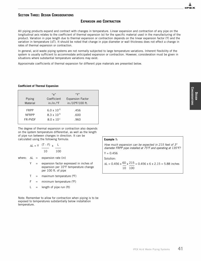
DESIGN
CON
SIDERATIONS
41IPEX Acid Waste Piping Systems
SECTION THREE: DESIGN CONSIDERATIONS
EXPANSION AND CONTRACTION
Coefficient of Thermal Expansion
“e” “Y”Piping Coefficient Expansion Factor
Material in./in./°F in./10ºF/100 ft.
FRPP 6.0 x 10⁻⁵ .456
NFRPP 8.3 x 10⁻⁵ .600
FR-PVDF 8.0 x 10⁻⁵ .960
The degree of thermal expansion or contraction also dependson the system temperature differential, as well as the lengthof pipe run between changes in direction. It can becalculated using the following formula:
ΔL = Y (T - F) x L
10 100
where: ΔL = expansion rate (in)
Y = expansion factor expressed in inches of expansion per 10°F temperature change per 100 ft. of pipe
T = maximum temperature (ºF)
F = minimum temperature (ºF)
L = length of pipe run (ft)
Note: Remember to allow for contraction when piping is to beexposed to temperatures substantially below installationtemperature.
Example 1:
How much expansion can be expected in 215 feet of 3"diameter FRPP pipe installed at 75°F and operating at 135°F?
Y = 0.456
Solution:
ΔL = 0.456 x 60 x 215 = 0.456 x 6 x 2.15 = 5.88 inches10 100
All piping products expand and contract with changes in temperature. Linear expansion and contraction of any pipe on thelongitudinal axis relates to the coefficient of thermal expansion (e) for the specific material used in the manufacturing of theproduct. Variation in pipe length due to thermal expansion or contraction depends on the linear expansion factor (Y) and thevariation in temperature (ΔT). It should be noted that change in pipe diameter or wall thickness does not effect a change inrates of thermal expansion or contraction.
In general, acid waste piping systems are not normally subjected to large temperature variations. Inherent flexibility of thesystem is usually sufficient to accommodate anticipated expansion or contraction. However, consideration must be given insituations where substantial temperature variations may exist.
Approximate coefficients of thermal expansion for different pipe materials are presented below.
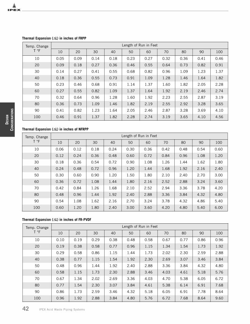
DESI
GN
CON
SIDE
RATI
ONS
42 IPEX Acid Waste Piping Systems
Thermal Expansion (ΔL) in inches of FRPP
Temp. ChangeT °F
Length of Run in Feet
10 20 30 40 50 60 70 80 90 100
10 0.05 0.09 0.14 0.18 0.23 0.27 0.32 0.36 0.41 0.46
20 0.09 0.18 0.27 0.36 0.46 0.55 0.64 0.73 0.82 0.91
30 0.14 0.27 0.41 0.55 0.68 0.82 0.96 1.09 1.23 1.37
40 0.18 0.36 0.55 0.73 0.91 1.09 1.28 1.46 1.64 1.82
50 0.23 0.46 0.68 0.91 1.14 1.37 1.60 1.82 2.05 2.28
60 0.27 0.55 0.82 1.09 1.37 1.64 1.92 2.19 2.46 2.74
70 0.32 0.64 0.96 1.28 1.60 1.92 2.23 2.55 2.87 3.19
80 0.36 0.73 1.09 1.46 1.82 2.19 2.55 2.92 3.28 3.65
90 0.41 0.82 1.23 1.64 2.05 2.46 2.87 3.28 3.69 4.10
100 0.46 0.91 1.37 1.82 2.28 2.74 3.19 3.65 4.10 4.56
Temp. ChangeT °F
Length of Run in Feet
10 20 30 40 50 60 70 80 90 100
10 0.06 0.12 0.18 0.24 0.30 0.36 0.42 0.48 0.54 0.60
20 0.12 0.24 0.36 0.48 0.60 0.72 0.84 0.96 1.08 1.20
30 0.18 0.36 0.54 0.72 0.90 1.08 1.26 1.44 1.62 1.80
40 0.24 0.48 0.72 0.96 1.20 1.44 1.68 1.92 2.16 2.40
50 0.30 0.60 0.90 1.20 1.50 1.80 2.10 2.40 2.70 3.00
60 0.36 0.72 1.08 1.44 1.80 2.16 2.52 2.88 3.24 3.60
70 0.42 0.84 1.26 1.68 2.10 2.52 2.94 3.36 3.78 4.20
80 0.48 0.96 1.44 1.92 2.40 2.88 3.36 3.84 4.32 4.80
90 0.54 1.08 1.62 2.16 2.70 3.24 3.78 4.32 4.86 5.40
100 0.60 1.20 1.80 2.40 3.00 3.60 4.20 4.80 5.40 6.00
Thermal Expansion (ΔL) in inches of NFRPP
Temp. ChangeT °F
Length of Run in Feet
10 20 30 40 50 60 70 80 90 100
10 0.10 0.19 0.29 0.38 0.48 0.58 0.67 0.77 0.86 0.96
20 0.19 0.38 0.58 0.77 0.96 1.15 1.34 1.54 1.73 1.92
30 0.29 0.58 0.86 1.15 1.44 1.73 2.02 2.30 2.59 2.88
40 0.38 0.77 1.15 1.54 1.92 2.30 2.69 3.07 3.46 3.84
50 0.48 0.96 1.44 1.92 2.40 2.88 3.36 3.84 4.32 4.80
60 0.58 1.15 1.73 2.30 2.88 3.46 4.03 4.61 5.18 5.76
70 0.67 1.34 2.02 2.69 3.36 4.03 4.70 5.38 6.05 6.72
80 0.77 1.54 2.30 3.07 3.84 4.61 5.38 6.14 6.91 7.68
90 0.86 1.73 2.59 3.46 4.32 5.18 6.05 6.91 7.78 8.64
100 0.96 1.92 2.88 3.84 4.80 5.76 6.72 7.68 8.64 9.60
Thermal Expansion (ΔL) in inches of FR-PVDF
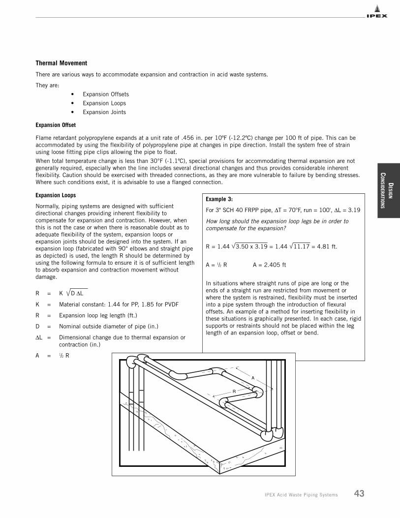
Thermal Movement
There are various ways to accommodate expansion and contraction in acid waste systems.
They are:
• Expansion Offsets
• Expansion Loops
• Expansion Joints
Expansion Offset
Flame retardant polypropylene expands at a unit rate of .456 in. per 10ºF (-12.2ºC) change per 100 ft of pipe. This can beaccommodated by using the flexibility of polypropylene pipe at changes in pipe direction. Install the system free of strainusing loose fitting pipe clips allowing the pipe to float.
When total temperature change is less than 30°F (-1.1ºC), special provisions for accommodating thermal expansion are notgenerally required, especially when the line includes several directional changes and thus provides considerable inherentflexibility. Caution should be exercised with threaded connections, as they are more vulnerable to failure by bending stresses.Where such conditions exist, it is advisable to use a flanged connection.
Expansion Loops
Normally, piping systems are designed with sufficientdirectional changes providing inherent flexibility tocompensate for expansion and contraction. However, whenthis is not the case or when there is reasonable doubt as toadequate flexibility of the system, expansion loops orexpansion joints should be designed into the system. If anexpansion loop (fabricated with 90° elbows and straight pipeas depicted) is used, the length R should be determined byusing the following formula to ensure it is of sufficient lengthto absorb expansion and contraction movement withoutdamage.
R = K D ΔL
K = Material constant: 1.44 for PP, 1.85 for PVDF
R = Expansion loop leg length (ft.)
D = Nominal outside diameter of pipe (in.)
ΔL = Dimensional change due to thermal expansion or contraction (in.)
A = 1/2 R
Example 3:
For 3" SCH 40 FRPP pipe, ΔT = 70°F, run = 100', ΔL = 3.19
How long should the expansion loop legs be in order tocompensate for the expansion?
R = 1.44 3.50 x 3.19 = 1.44 11.17 = 4.81 ft.
A = 1/2 R A = 2.405 ft
In situations where straight runs of pipe are long or theends of a straight run are restricted from movement orwhere the system is restrained, flexibility must be insertedinto a pipe system through the introduction of flexuraloffsets. An example of a method for inserting flexibility inthese situations is graphically presented. In each case, rigidsupports or restraints should not be placed within the leglength of an expansion loop, offset or bend.
DESIGN
CON
SIDERATIONS
43IPEX Acid Waste Piping Systems
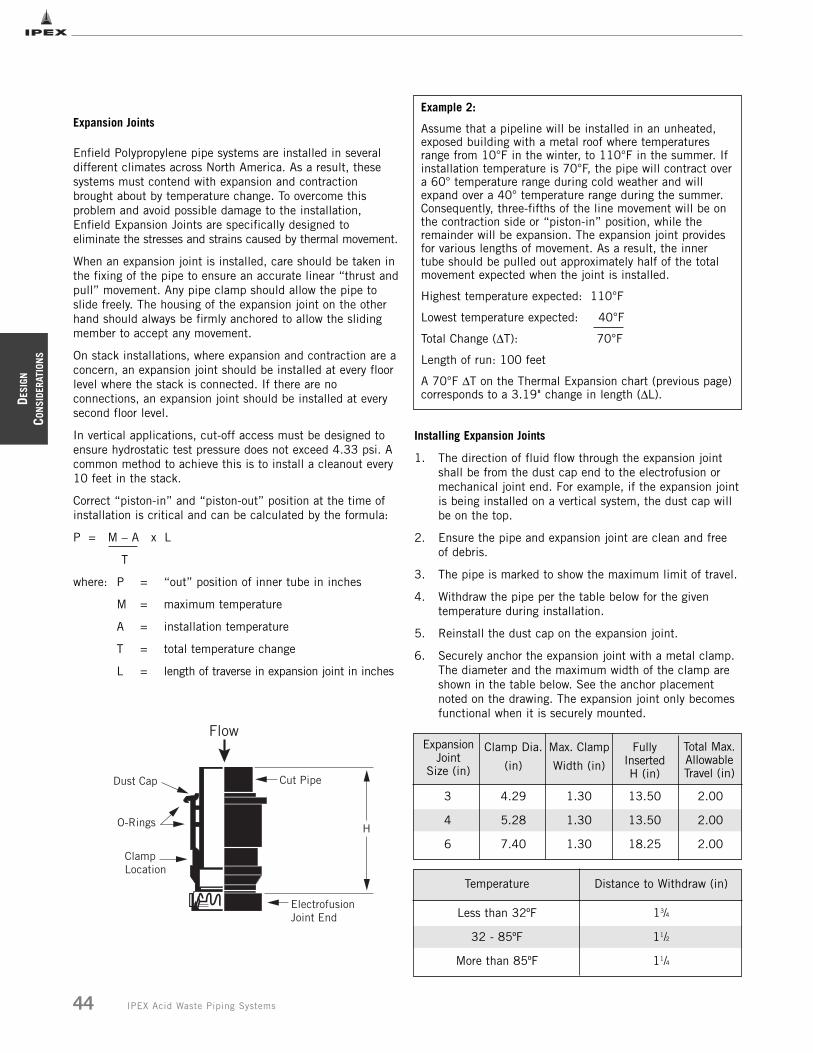
DESI
GN
CON
SIDE
RATI
ONS
44 IPEX Acid Waste Piping Systems
Expansion Joints
Enfield Polypropylene pipe systems are installed in severaldifferent climates across North America. As a result, thesesystems must contend with expansion and contractionbrought about by temperature change. To overcome thisproblem and avoid possible damage to the installation,Enfield Expansion Joints are specifically designed toeliminate the stresses and strains caused by thermal movement.
When an expansion joint is installed, care should be taken inthe fixing of the pipe to ensure an accurate linear “thrust andpull” movement. Any pipe clamp should allow the pipe toslide freely. The housing of the expansion joint on the otherhand should always be firmly anchored to allow the slidingmember to accept any movement.
On stack installations, where expansion and contraction are aconcern, an expansion joint should be installed at every floorlevel where the stack is connected. If there are noconnections, an expansion joint should be installed at everysecond floor level.
In vertical applications, cut-off access must be designed toensure hydrostatic test pressure does not exceed 4.33 psi. Acommon method to achieve this is to install a cleanout every10 feet in the stack.
Correct “piston-in” and “piston-out” position at the time ofinstallation is critical and can be calculated by the formula:
P = M – A x L
T
where: P = “out” position of inner tube in inches
M = maximum temperature
A = installation temperature
T = total temperature change
L = length of traverse in expansion joint in inches
Example 2:
Assume that a pipeline will be installed in an unheated,exposed building with a metal roof where temperaturesrange from 10°F in the winter, to 110°F in the summer. Ifinstallation temperature is 70°F, the pipe will contract overa 60° temperature range during cold weather and willexpand over a 40° temperature range during the summer.Consequently, three-fifths of the line movement will be onthe contraction side or “piston-in” position, while theremainder will be expansion. The expansion joint providesfor various lengths of movement. As a result, the innertube should be pulled out approximately half of the totalmovement expected when the joint is installed.
Highest temperature expected: 110°F
Lowest temperature expected: 40°F
Total Change (ΔT): 70°F
Length of run: 100 feet
A 70°F ΔT on the Thermal Expansion chart (previous page)corresponds to a 3.19" change in length (ΔL).
Installing Expansion Joints
1. The direction of fluid flow through the expansion joint shall be from the dust cap end to the electrofusion or mechanical joint end. For example, if the expansion jointis being installed on a vertical system, the dust cap will be on the top.
2. Ensure the pipe and expansion joint are clean and free of debris.
3. The pipe is marked to show the maximum limit of travel.
4. Withdraw the pipe per the table below for the given temperature during installation.
5. Reinstall the dust cap on the expansion joint.
6. Securely anchor the expansion joint with a metal clamp. The diameter and the maximum width of the clamp are shown in the table below. See the anchor placement noted on the drawing. The expansion joint only becomes functional when it is securely mounted.
3
4
6
4.29
5.28
7.40
1.30
1.30
1.30
13.50
13.50
18.25
2.00
2.00
2.00
Clamp Dia.
(in)
Max. Clamp
Width (in)
FullyInserted H (in)
Less than 32ºF
32 - 85ºF
More than 85ºF
13/4
11/2
11/4
Temperature Distance to Withdraw (in)
ExpansionJoint
Size (in)
Total Max.AllowableTravel (in)
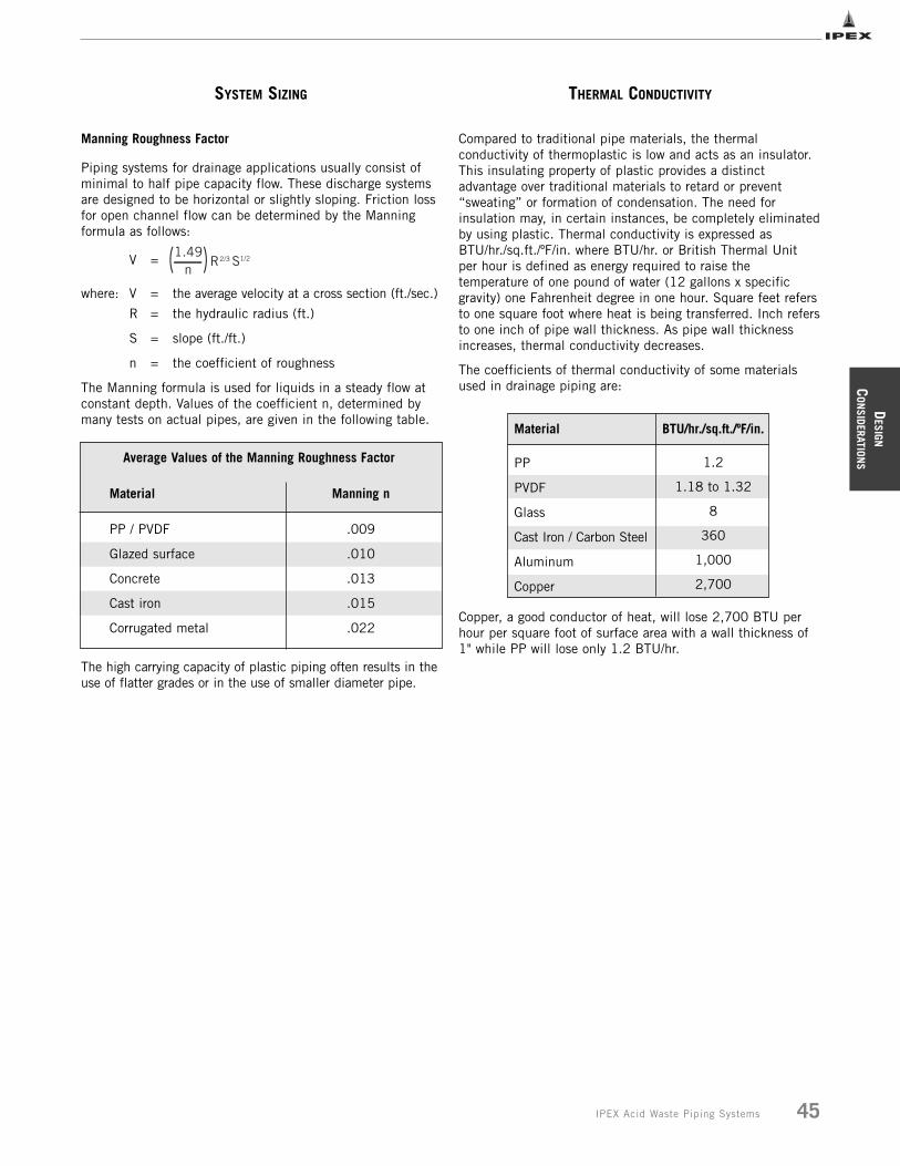
DESIGN
CON
SIDERATIONS
45IPEX Acid Waste Piping Systems
Compared to traditional pipe materials, the thermalconductivity of thermoplastic is low and acts as an insulator.This insulating property of plastic provides a distinctadvantage over traditional materials to retard or prevent“sweating” or formation of condensation. The need forinsulation may, in certain instances, be completely eliminatedby using plastic. Thermal conductivity is expressed asBTU/hr./sq.ft./ºF/in. where BTU/hr. or British Thermal Unitper hour is defined as energy required to raise thetemperature of one pound of water (12 gallons x specificgravity) one Fahrenheit degree in one hour. Square feet refersto one square foot where heat is being transferred. Inch refersto one inch of pipe wall thickness. As pipe wall thicknessincreases, thermal conductivity decreases.
The coefficients of thermal conductivity of some materialsused in drainage piping are:
Copper, a good conductor of heat, will lose 2,700 BTU perhour per square foot of surface area with a wall thickness of1" while PP will lose only 1.2 BTU/hr.
SYSTEM SIZING
Manning Roughness Factor
Piping systems for drainage applications usually consist ofminimal to half pipe capacity flow. These discharge systemsare designed to be horizontal or slightly sloping. Friction lossfor open channel flow can be determined by the Manningformula as follows:
V =
where: V = the average velocity at a cross section (ft./sec.)
R = the hydraulic radius (ft.)
S = slope (ft./ft.)
n = the coefficient of roughness
The Manning formula is used for liquids in a steady flow atconstant depth. Values of the coefficient n, determined bymany tests on actual pipes, are given in the following table.
The high carrying capacity of plastic piping often results in theuse of flatter grades or in the use of smaller diameter pipe.
S
Material
PP / PVDF
Glazed surface
Concrete
Cast iron
Corrugated metal
Manning n
.009
.010
.013
.015
.022
Average Values of the Manning Roughness Factor
THERMAL CONDUCTIVITY
BTU/hr./sq.ft./ºF/in.
1.2
1.18 to 1.32
8
360
1,000
2,700
Material
PP
PVDF
Glass
Cast Iron / Carbon Steel
Aluminum
Copper
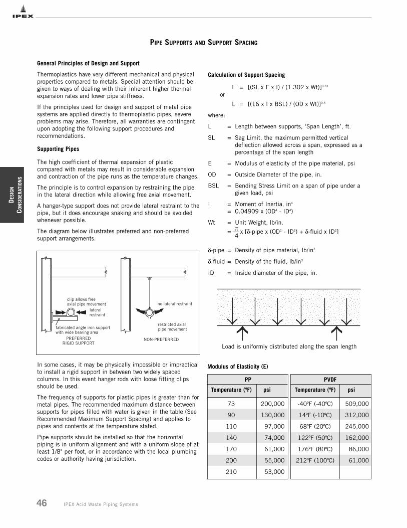
DESI
GN
CON
SIDE
RATI
ONS
46 IPEX Acid Waste Piping Systems
PIPE SUPPORTS AND SUPPORT SPACING
General Principles of Design and Support
Thermoplastics have very different mechanical and physicalproperties compared to metals. Special attention should begiven to ways of dealing with their inherent higher thermalexpansion rates and lower pipe stiffness.
If the principles used for design and support of metal pipesystems are applied directly to thermoplastic pipes, severeproblems may arise. Therefore, all warranties are contingentupon adopting the following support procedures andrecommendations.
Supporting Pipes
The high coefficient of thermal expansion of plasticcompared with metals may result in considerable expansionand contraction of the pipe runs as the temperature changes.
The principle is to control expansion by restraining the pipein the lateral direction while allowing free axial movement.
A hanger-type support does not provide lateral restraint to thepipe, but it does encourage snaking and should be avoidedwhenever possible.
The diagram below illustrates preferred and non-preferredsupport arrangements.
In some cases, it may be physically impossible or impracticalto install a rigid support in between two widely spacedcolumns. In this event hanger rods with loose fitting clipsshould be used.
The frequency of supports for plastic pipes is greater than formetal pipes. The recommended maximum distance betweensupports for pipes filled with water is given in the table (SeeRecommended Maximum Support Spacing) and applies topipes and contents at the temperature stated.
Pipe supports should be installed so that the horizontalpiping is in uniform alignment and with a uniform slope of atleast 1/8" per foot, or in accordance with the local plumbingcodes or authority having jurisdiction.
Calculation of Support Spacing
L = [(SL x E x I) / (1.302 x Wt)]0.33
or
L = [(16 x I x BSL) / (OD x Wt)]0.5
where:
L = Length between supports, ‘Span Length’, ft.
SL = Sag Limit, the maximum permitted vertical deflection allowed across a span, expressed as a percentage of the span length
E = Modulus of elasticity of the pipe material, psi
OD = Outside Diameter of the pipe, in.
BSL = Bending Stress Limit on a span of pipe under a given load, psi
I = Moment of Inertia, in4
= 0.04909 x (OD4 - ID4)
Wt = Unit Weight, lb/in.
= π x [δ-pipe x (OD2 - ID2) + δ-fluid x ID2]4
δ-pipe = Density of pipe material, lb/in3
δ-fluid = Density of the fluid, lb/in3
ID = Inside diameter of the pipe, in.
NON-PREFERRED
no lateral restraint
restricted axialpipe movement
PREFERREDRIGID SUPPORT
clip allows freeaxial pipe movement
lateralrestraint
fabricated angle iron supportwith wide bearing area
Load is uniformly distributed along the span length
Modulus of Elasticity (E)
PP PVDF
Temperature (ºF)
73
90
110
140
170
200
210
psi
200,000
130,000
97,000
74,000
61,000
55,000
53,000
psi
509,000
312,000
245,000
162,000
86,000
61,000
Temperature (ºF)
-40ºF (-40ºC)
14ºF (-10ºC)
68ºF (20ºC)
122ºF (50ºC)
176ºF (80ºC)
212ºF (100ºC)
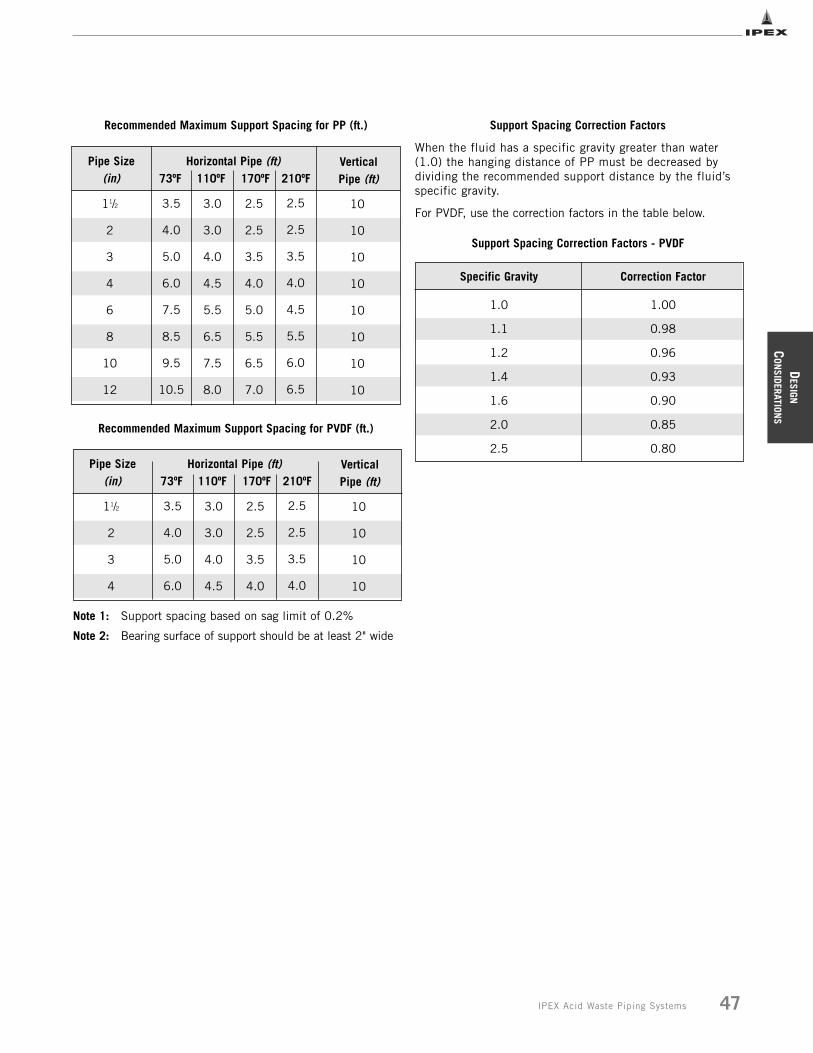
DESIGN
CON
SIDERATIONS
47IPEX Acid Waste Piping Systems
Recommended Maximum Support Spacing for PP (ft.)
Recommended Maximum Support Spacing for PVDF (ft.)
Note 1: Support spacing based on sag limit of 0.2%
Note 2: Bearing surface of support should be at least 2" wide
Support Spacing Correction Factors
When the fluid has a specific gravity greater than water(1.0) the hanging distance of PP must be decreased bydividing the recommended support distance by the fluid’sspecific gravity.
For PVDF, use the correction factors in the table below.
Support Spacing Correction Factors - PVDF
Pipe Size(in)
Horizontal Pipe (ft)73ºF 110ºF 170ºF 210ºF
Vertical Pipe (ft)
3.5
4.0
5.0
6.0
7.5
8.5
9.5
10.5
3.0
3.0
4.0
4.5
5.5
6.5
7.5
8.0
2.5
2.5
3.5
4.0
5.0
5.5
6.5
7.0
2.5
2.5
3.5
4.0
4.5
5.5
6.0
6.5
11/2
2
3
4
6
8
10
12
10
10
10
10
10
10
10
10
Pipe Size(in)
Horizontal Pipe (ft)73ºF 110ºF 170ºF 210ºF
Vertical Pipe (ft)
3.5
4.0
5.0
6.0
3.0
3.0
4.0
4.5
2.5
2.5
3.5
4.0
2.5
2.5
3.5
4.0
11/2
2
3
4
10
10
10
10
Specific Gravity Correction Factor
1.0
1.1
1.2
1.4
1.6
2.0
2.5
1.00
0.98
0.96
0.93
0.90
0.85
0.80
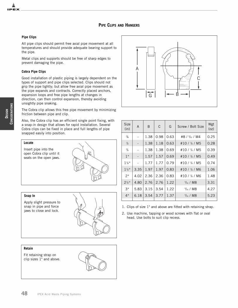
DESI
GN
CON
SIDE
RATI
ONS
48 IPEX Acid Waste Piping Systems
PIPE CLIPS AND HANGERS
Pipe Clips
All pipe clips should permit free axial pipe movement at alltemperatures and should provide adequate bearing support tothe pipe.
Metal clips and supports should be free of sharp edges toprevent damaging the pipe.
Cobra Pipe Clips
Good installation of plastic piping is largely dependent on thetypes of support and pipe clips selected. Clips should notgrip the pipe tightly; but allow free axial pipe movement asthe pipe expands and contracts. Correctly placed anchors,expansion loops and free pipe lengths at changes indirection, can then control expansion, thereby avoidingunsightly pipe snaking.
The Cobra clip allows this free pipe movement by minimizingfriction between pipe and clip.
Also, the Cobra clip has an efficient single point fixing, witha snap-in design that allows for rapid installation. SeveralCobra clips can be fixed in place and full lengths of pipesnapped easily into position.
Locate
Insert pipe into theopen Cobra clip until itseats on the open jaws.
Snap In
Apply slight pressure tosnap in pipe and forcejaws to close and lock.
Retain
Fit retaining strap onclip sizes 1" and above.
3/8
1/2
3/4
1*
11/4*
11/2*
2*
21/2*
3*
4*
-
-
-
-
-
3.35
4.02
4.80
5.83
6.18
1.38
1.38
1.38
1.57
1.77
1.97
2.36
2.76
3.15
3.54
0.98
1.18
1.38
1.57
1.77
1.97
2.36
2.76
3.54
3.77
0.25
0.28
0.39
0.49
0.74
1.06
1.48
3.31
4.27
5.23
0.63
0.63
0.69
0.69
0.79
0.83
0.83
1.22
1.22
1.37
#8 / 5/32 / M4
#10 / 1/4 / M5
#10 / 1/4 / M5
#10 / 1/4 / M5
#10 / 1/4 / M5
#10 / 1/4 / M6
#10 / 1/4 / M6
5/16 / M8
5/16 / M8
5/16 / M8
Size(in)
A B CWgt(oz)
G Screw / Bolt Size
1. Clips of size 1" and above are fitted with retaining strap.
2. Use machine, tapping or wood screws with flat or oval head. Use bolts to suit clip recess.
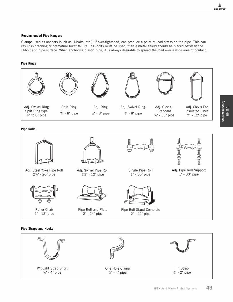
DESIGN
CON
SIDERATIONS
49IPEX Acid Waste Piping Systems
Recommended Pipe Hangers
Clamps used as anchors (such as U-bolts, etc.), if over-tightened, can produce a point-of-load stress on the pipe. This canresult in cracking or premature burst failure. If U-bolts must be used, then a metal shield should be placed between the U-bolt and pipe surface. When anchoring plastic pipe, it is always desirable to spread the load over a wide area of contact.
Pipe Rings
Adj. Swivel Ring Split Ring type
3/4" to 8" pipe
Split Ring
3/8" - 8" pipe
Adj. Ring
1/2" - 8" pipe
Adj. Swivel Ring
1/2" - 8" pipe
Adj. Clevis -Standard
1/2" - 30" pipe
Adj. Clevis ForInsulated Lines
3/4" - 12" pipe
Pipe Rolls
Adj. Steel Yoke Pipe Roll 21/2" - 20" pipe
Adj. Swivel Pipe Roll 21/2" - 12" pipe
Single Pipe Roll1" - 30" pipe
Adj. Pipe Roll Support1" - 30" pipe
Roller Chair2" - 12" pipe
Pipe Roll and Plate2" - 24" pipe
Pipe Roll Stand Complete2" - 42" pipe
Pipe Straps and Hooks
Wrought Strap Short1/2" - 4" pipe
One Hole Clamp3/8" - 4" pipe
Tin Strap1/2" - 2" pipe
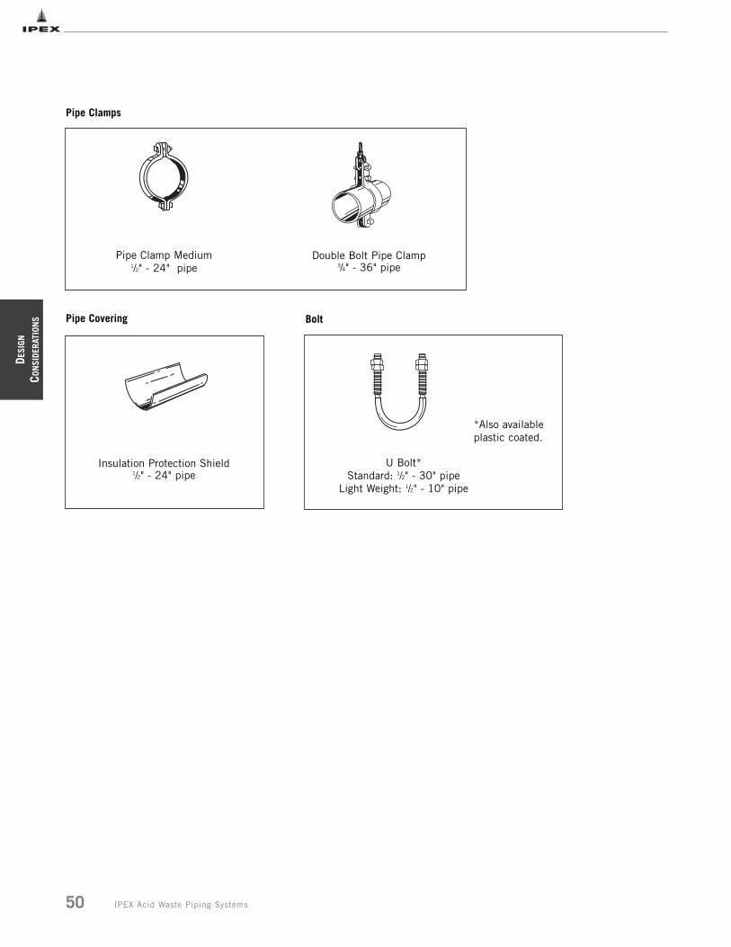
DESI
GN
CON
SIDE
RATI
ONS
50 IPEX Acid Waste Piping Systems
Pipe Clamps
Pipe Clamp Medium1/2" - 24" pipe
Double Bolt Pipe Clamp3/4" - 36" pipe
Pipe Covering
Insulation Protection Shield1/2" - 24" pipe
Bolt
U Bolt* Standard: 1/2" - 30" pipe
Light Weight: 1/2" - 10" pipe
*Also availableplastic coated.
DESIGN
CON
SIDERATIONS
51IPEX Acid Waste Piping Systems
HANDLING AND STORAGE
Thermoplastics are strong, lightweight materials, about onefifth the weight of steel or cast iron. Piping made of thismaterial is easily handled and, as a result, there is atendency for it to be thrown about on the jobsite. Care shouldbe taken in handling and storage to prevent damage to thepipe. Some general guidelines are as follows:
• Make sure the pipe is adequately supported at all times.Avoid stacking pipe in large piles, since the pipe at thebottom may incur high loads.
• For long-term storage, use pipe racks to support the pipecontinuously along its length. If this is not possible,supports of at least 3 in. bearing width, at spacings notgreater than 3 ft centers, are recommended. Pipe shouldnot be stored more than seven layers high. Sharp cornerson metal racks should be avoided.
• Pipe is often supplied in crates. Take care whenunloading crates, and avoid using metal slings or wireropes. Crates may be stacked four high in the field.
• Exercise care while handling pipe. Damage may occur ifpipe collides with sharp corners, or is dropped.Prolongedexposure of Enfield and Labline FRPP and NFRPP to thedirect rays of the sun will not damage the pipe. However,some mild discoloration may take place in the form of amilky film on the exposed surfaces. This change in colormerely indicates that there has been a harmlesschemical transformation at the surface of the pipe. Asmall reduction in impact strength could occur at thediscolored surfaces; but it is of a very small order andnot enough to cause problems in field installation.
Prolonged Outdoor Exposure
Prolonged exposure of Enfield and labline FRPP and NFRPPto the direct rays of the sun will not damage the pipe.However, some mild discoloration may take place in the formof a milky film on the exposed surfaces. This change in colormerely indicates that there has been a harmless chemicaltransformation at the surface of the pipe. A small reductionin impact strength could occur at the discolored surfaces; butit is of a very small order and not enough to cause problemsin field installation.
Unlike many other thermoplastic materials, FR-PVDF is notsusceptible to degradation due to UV exposure. Therefore,prolonged exposure of FR-PVDF pipe to the direct rays of thesun will not damage the pipe. For purposes of cleanlinesshowever, it is good practice to keep pipe and fittings under aprotective cover when stored outdoors.
Painting
PP pipe and fittings can be easily protected from ultravioletoxidation by painting with a heavily pigmented, exteriorwater-based latex paint. The color of the paint is notimportant; the pigment merely acts as an ultraviolet screenand prevents sunlight discoloration. White or some other lightcolor is recommended since it helps reduce pipe temperature.The latex paint must be thickly applied as an opaque coatingon pipe and fittings that have been cleaned well, very lightlysanded, and primed with a latex base primer.
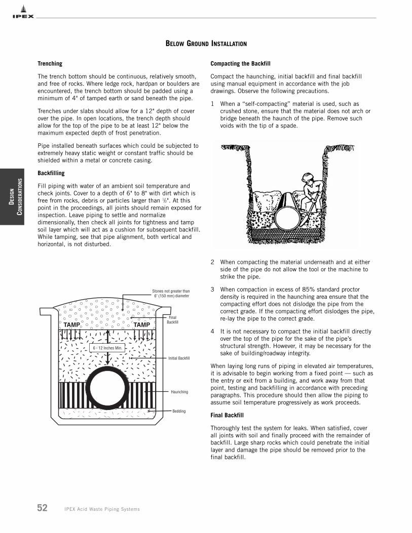
DESI
GN
CON
SIDE
RATI
ONS
52 IPEX Acid Waste Piping Systems
BELOW GROUND INSTALLATION
Trenching
The trench bottom should be continuous, relatively smooth,and free of rocks. Where ledge rock, hardpan or boulders areencountered, the trench bottom should be padded using aminimum of 4" of tamped earth or sand beneath the pipe.
Trenches under slabs should allow for a 12" depth of coverover the pipe. In open locations, the trench depth shouldallow for the top of the pipe to be at least 12" below themaximum expected depth of frost penetration.
Pipe installed beneath surfaces which could be subjected toextremely heavy static weight or constant traffic should beshielded within a metal or concrete casing.
Backfilling
Fill piping with water of an ambient soil temperature andcheck joints. Cover to a depth of 6" to 8" with dirt which isfree from rocks, debris or particles larger than 1/2". At thispoint in the proceedings, all joints should remain exposed forinspection. Leave piping to settle and normalizedimensionally, then check all joints for tightness and tampsoil layer which will act as a cushion for subsequent backfill.While tamping, see that pipe alignment, both vertical andhorizontal, is not disturbed.
Compacting the Backfill
Compact the haunching, initial backfill and final backfillusing manual equipment in accordance with the jobdrawings. Observe the following precautions.
1 When a “self-compacting” material is used, such as crushed stone, ensure that the material does not arch or bridge beneath the haunch of the pipe. Remove such voids with the tip of a spade.
2 When compacting the material underneath and at either side of the pipe do not allow the tool or the machine to strike the pipe.
3 When compaction in excess of 85% standard proctor density is required in the haunching area ensure that the compacting effort does not dislodge the pipe from the correct grade. If the compacting effort dislodges the pipe,re-lay the pipe to the correct grade.
4 It is not necessary to compact the initial backfill directly over the top of the pipe for the sake of the pipe’s structural strength. However, it may be necessary for the sake of building/roadway integrity.
When laying long runs of piping in elevated air temperatures, it is advisable to begin working from a fixed point __ such asthe entry or exit from a building, and work away from thatpoint, testing and backfilling in accordance with precedingparagraphs. This procedure should then allow the piping toassume soil temperature progressively as work proceeds.
Final Backfill
Thoroughly test the system for leaks. When satisfied, cover all joints with soil and finally proceed with the remainder ofbackfill. Large sharp rocks which could penetrate the initiallayer and damage the pipe should be removed prior to the final backfill.
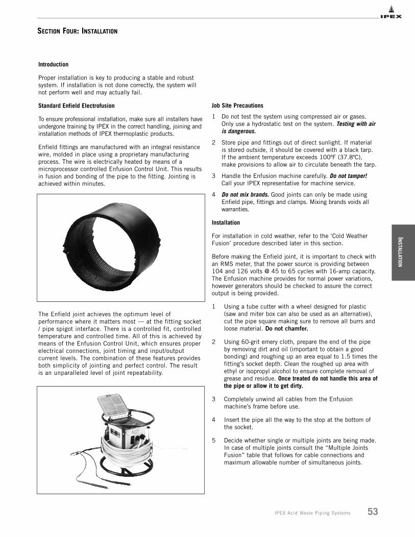
INSTALLATION
53IPEX Acid Waste Piping Systems
SECTION FOUR: INSTALLATION
Job Site Precautions
1 Do not test the system using compressed air or gases. Only use a hydrostatic test on the system. Testing with air is dangerous.
2 Store pipe and fittings out of direct sunlight. If material is stored outside, it should be covered with a black tarp. If the ambient temperature exceeds 100ºF (37.8ºC), make provisions to allow air to circulate beneath the tarp.
3 Handle the Enfusion machine carefully. Do not tamper!Call your IPEX representative for machine service.
4 Do not mix brands. Good joints can only be made using Enfield pipe, fittings and clamps. Mixing brands voids all warranties.
Installation
For installation in cold weather, refer to the ‘Cold WeatherFusion’ procedure described later in this section.
Before making the Enfield joint, it is important to check withan RMS meter, that the power source is providing between104 and 126 volts @ 45 to 65 cycles with 16-amp capacity.The Enfusion machine provides for normal power variations,however generators should be checked to assure the correctoutput is being provided.
1 Using a tube cutter with a wheel designed for plastic (saw and miter box can also be used as an alternative), cut the pipe square making sure to remove all burrs and loose material. Do not chamfer.
2 Using 60-grit emery cloth, prepare the end of the pipe by removing dirt and oil (important to obtain a good bonding) and roughing up an area equal to 1.5 times thefitting’s socket depth. Clean the roughed up area with ethyl or isopropyl alcohol to ensure complete removal of grease and residue. Once treated do not handle this area ofthe pipe or allow it to get dirty.
3 Completely unwind all cables from the Enfusion machine’s frame before use.
4 Insert the pipe all the way to the stop at the bottom of the socket.
5 Decide whether single or multiple joints are being made.In case of multiple joints consult the “Multiple Joints Fusion” table that follows for cable connections and maximum allowable number of simultaneous joints.
Introduction
Proper installation is key to producing a stable and robustsystem. If installation is not done correctly, the system willnot perform well and may actually fail.
Standard Enfield Electrofusion
To ensure professional installation, make sure all installers haveundergone training by IPEX in the correct handling, joining andinstallation methods of IPEX thermoplastic products.
Enfield fittings are manufactured with an integral resistancewire, molded in place using a proprietary manufacturingprocess. The wire is electrically heated by means of amicroprocessor controlled Enfusion Control Unit. This resultsin fusion and bonding of the pipe to the fitting. Jointing isachieved within minutes.
The Enfield joint achieves the optimum level ofperformance where it matters most __ at the fitting socket/ pipe spigot interface. There is a controlled fit, controlledtemperature and controlled time. All of this is achieved bymeans of the Enfusion Control Unit, which ensures properelectrical connections, joint timing and input/outputcurrent levels. The combination of these features providesboth simplicity of jointing and perfect control. The resultis an unparalleled level of joint repeatability.
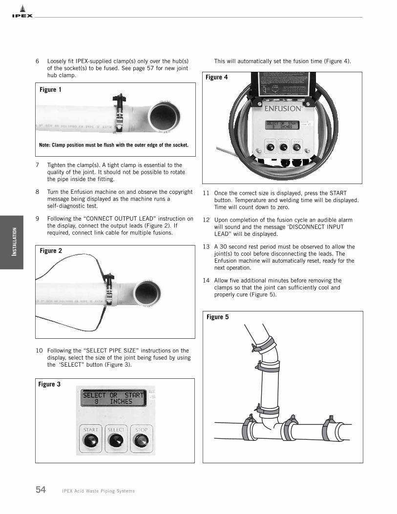
INST
ALLA
TION
54 IPEX Acid Waste Piping Systems
6 Loosely fit IPEX-supplied clamp(s) only over the hub(s) of the socket(s) to be fused. See page 57 for new joint hub clamp.
7 Tighten the clamp(s). A tight clamp is essential to the quality of the joint. It should not be possible to rotate the pipe inside the fitting.
8 Turn the Enfusion machine on and observe the copyright message being displayed as the machine runs a self-diagnostic test.
9 Following the “CONNECT OUTPUT LEAD” instruction onthe display, connect the output leads (Figure 2). If required, connect link cable for multiple fusions.
10 Following the “SELECT PIPE SIZE” instructions on the display, select the size of the joint being fused by using the ‘SELECT” button (Figure 3).
This will automatically set the fusion time (Figure 4).
11 Once the correct size is displayed, press the START button. Temperature and welding time will be displayed. Time will count down to zero.
12 Upon completion of the fusion cycle an audible alarm will sound and the message ‘DISCONNECT INPUT LEAD” will be displayed.
13 A 30 second rest period must be observed to allow the joint(s) to cool before disconnecting the leads. The Enfusion machine will automatically reset, ready for the next operation.
14 Allow five additional minutes before removing the clamps so that the joint can sufficiently cool and properly cure (Figure 5).
Figure 3
Figure 2
Figure 4
Figure 1
Figure 5
Note: Clamp position must be flush with the outer edge of the socket.
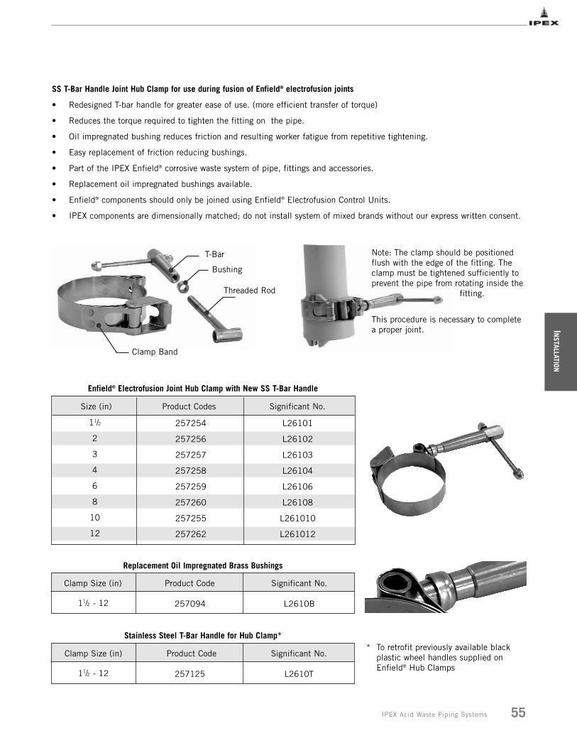
INSTALLATION
55IPEX Acid Waste Piping Systems
SS T-Bar Handle Joint Hub Clamp for use during fusion of Enfield® electrofusion joints
• Redesigned T-bar handle for greater ease of use. (more efficient transfer of torque)
• Reduces the torque required to tighten the fitting on the pipe.
• Oil impregnated bushing reduces friction and resulting worker fatigue from repetitive tightening.
• Easy replacement of friction reducing bushings.
• Part of the IPEX Enfield® corrosive waste system of pipe, fittings and accessories.
• Replacement oil impregnated bushings available.
• Enfield® components should only be joined using Enfield® Electrofusion Control Units.
• IPEX components are dimensionally matched; do not install system of mixed brands without our express written consent.
Clamp Band
T-Bar
Bushing
Threaded Rod
Note: The clamp should be positionedflush with the edge of the fitting. Theclamp must be tightened sufficiently toprevent the pipe from rotating inside the
fitting.
This procedure is necessary to completea proper joint.
11/2
2
3
4
6
8
10
12
L26101
L26102
L26103
L26104
L26106
L26108
L261010
L261012
257254
257256
257257
257258
257259
257260
257255
257262
Product CodesSize (in) Significant No.
Enfield® Electrofusion Joint Hub Clamp with New SS T-Bar Handle
Replacement Oil Impregnated Brass Bushings
Stainless Steel T-Bar Handle for Hub Clamp*
11/2 - 12 L2610B257094
Product CodeClamp Size (in) Significant No.
11/2 - 12 L2610T257125
Product CodeClamp Size (in) Significant No.* To retrofit previously available black
plastic wheel handles supplied onEnfield® Hub Clamps
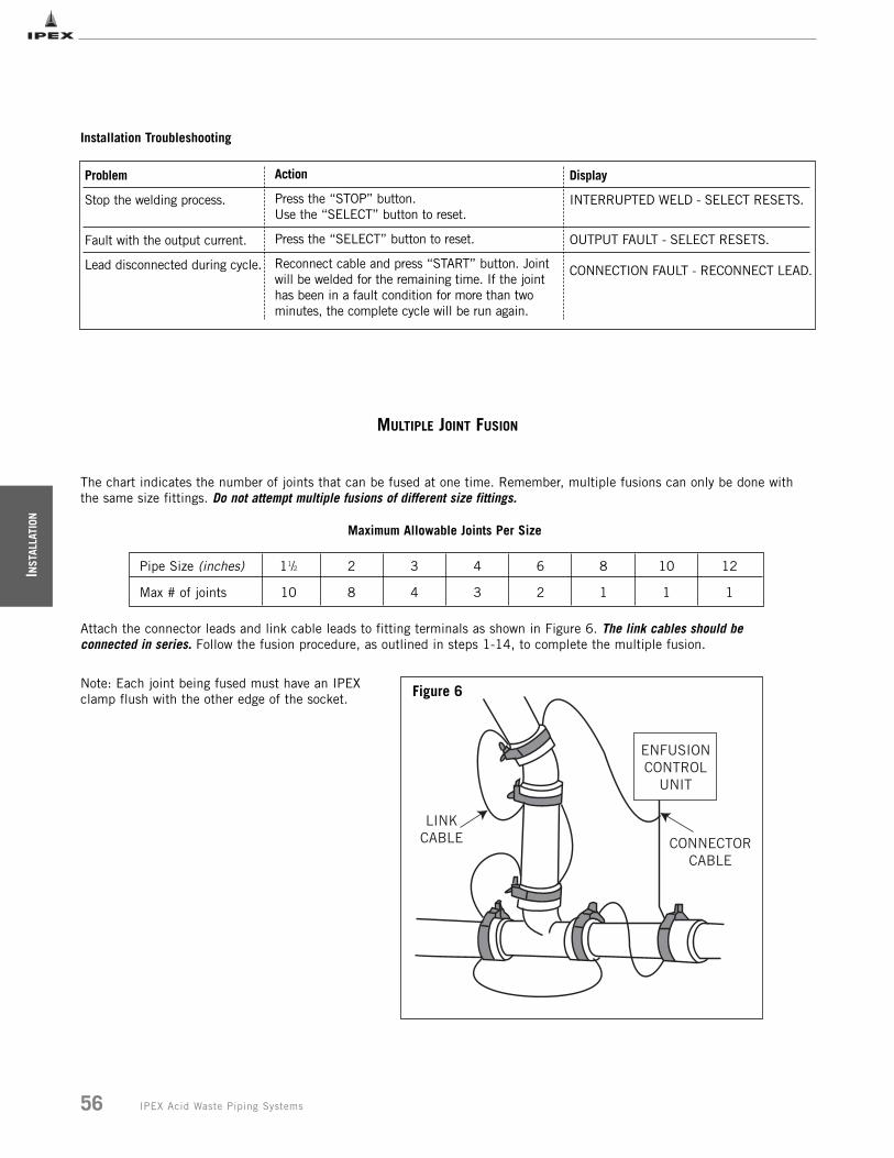
INST
ALLA
TION
56 IPEX Acid Waste Piping Systems
The chart indicates the number of joints that can be fused at one time. Remember, multiple fusions can only be done withthe same size fittings. Do not attempt multiple fusions of different size fittings.
Attach the connector leads and link cable leads to fitting terminals as shown in Figure 6. The link cables should be connected in series. Follow the fusion procedure, as outlined in steps 1-14, to complete the multiple fusion.
11/2
10
2
8
3
4
4
3
6
2
8
1
10
1
12
1
Pipe Size (inches)
Max # of joints
Maximum Allowable Joints Per Size
Installation Troubleshooting
Problem
Stop the welding process.
Fault with the output current.
Lead disconnected during cycle.
Action
Press the “STOP” button. Use the “SELECT” button to reset.
Press the “SELECT” button to reset.
Reconnect cable and press “START” button. Jointwill be welded for the remaining time. If the jointhas been in a fault condition for more than two minutes, the complete cycle will be run again.
Display
INTERRUPTED WELD - SELECT RESETS.
OUTPUT FAULT - SELECT RESETS.
CONNECTION FAULT - RECONNECT LEAD.
ENFUSIONCONTROL
UNIT
CONNECTORCABLE
LINKCABLE
Figure 6
MULTIPLE JOINT FUSION
Note: Each joint being fused must have an IPEXclamp flush with the other edge of the socket.
INSTALLATION
57IPEX Acid Waste Piping Systems
COLD WEATHER FUSION
Whenever possible pipe and fittings should be stored indoors. It is always preferable to perform pipe preparation and weldingin a protected environment. However, should that not be possible, during cold weather (particularly at freezing or below) it isrecommended that both pipe and fittings be stored in similar ambient temperature and conditions.
In addition, when the actual welding takes place in freezing or sub-freezing environments, this cold weather pre-fusionprocedure must be followed.
1 Follow steps 1 through 9 of Standard Enfield Electrofusion Installation.
2 When the “SELECT PIPE SIZE” prompt appears on the screen keep pushing the select button until all pipe sizes
have been displayed.
3 Next will appear the first flash cycle: 11/2" to 2".
4 If the fitting(s) being welded is within this flash range, press START.
5 If the fitting(s) being welded is not included in this flash range, press the SELECT button one more time to display
the second flash cycle: 3" through 12".
6 Press START.
7 Upon completion of the flash cycle, the display will show the “DISCONNECT INPUT LEAD” message. Do not
disconnect the leads.
8 Tighten clamps if necessary (see notes below).
9 Allow the joints to cool for 5 minutes before beginning the fusion cycle.
10 After 5 minutes, continue with steps 10 through 14 of the Standard Enfield Electrofusion Installation procedure.
NOTES
Screen the joints being fused from the wind in very cold conditions to prevent heat loss.
Particular care must be taken to adequately tighten the clamps during extremely cold weather because of increased stiffnessof the materials. One or two additional turns of the tightening screw might be required, above and beyond what is commonlysufficient in fair weather conditions. This is particularly true when welding large diameters.
The additional tightening of the clamps, designed to eliminate any gap between the pipe and the fitting, should be performedtowards the end of the flash cycle. However, care must be taken not to overtighten to avoid distorting or crushing the fittingjoint.
Marking of the pipe (indicating socket depth) is also recommended to assure that the pipe remains fully seated in the socketduring the fusion cycle.
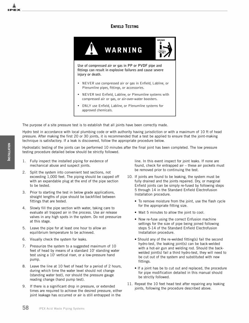
INST
ALLA
TION
58 IPEX Acid Waste Piping Systems
ENFIELD TESTING
The purpose of a site pressure test is to establish that all joints have been correctly made.
Hydro test in accordance with local plumbing code or with authority having jurisdiction or with a maximum of 10 ft of headpressure. After making the first 20 or 30 joints, it is recommended that a test be applied to ensure that the joint-makingtechnique is satisfactory. If a leak is discovered, follow the appropriate procedure below.
Hydrostatic testing of the joints can be performed 10 minutes after the final joint has been completed. The low pressuretesting procedure detailed below should be strictly followed.
1. Fully inspect the installed piping for evidence of mechanical abuse and suspect joints.
2. Split the system into convenient test sections, not exceeding 1,000 feet. The piping should be capped off with an expandable plug at the end of the pipe section to be tested.
3. Prior to starting the test in below grade applications, straight lengths of pipe should be backfilled between fittings that are tested.
4. Slowly fill the pipe section with water, taking care to evaluate all trapped air in the process. Use air release valves in any high spots in the system. Do not pressurizeat this stage.
5. Leave the pipe for at least one hour to allow an equilibrium temperature to be achieved.
6. Visually check the system for leaks.
7. Pressurize the system to a suggested maximum of 10 feet of head by means of a standard 10' standing water test using a 10' vertical riser, or a low-pressure hand pump.
8. Leave the line at 10 feet of head for a period of 2 hours,during which time the water level should not change (standing water test), nor should the pressure gauge reading change (hand pump test).
9. If there is a significant drop in pressure, or extended times are required to achieve the desired pressure, eitherjoint leakage has occurred or air is still entrapped in the
line. In this event inspect for joint leaks. If none are found, check for entrapped air – these air pockets must be removed prior to continuing the test.
10. If joints are found to be leaking, the system must be fully drained and the joints repaired. Dry, or marginal Enfield joints can be simply re-fused by following steps 5 through 14 in the Standard Enfield Electrofusion Installation procedure.
• To remove moisture from the joint, use the flash cycle for the appropriate fitting size.
• Wait 5 minutes to allow the joint to cool.
• Now re-fuse using the correct Enfusion machine settings for the size of pipe being joined following steps 5-14 of the Standard Enfield Electrofusion Installation procedure.
• Should any of the re-welded fitting(s) fail the second hydro-test, the leaking joint(s) can be back-welded with a hot-air gun and welding rod. Should the back-welded joint(s) fail a third hydro-test, they will need tobe cut out of the system and substituted with new fittings.
• If a joint has be to cut out and replaced, the procedurefor pipe modification detailed in this manual should be strictly followed.
11. Repeat the 10 feet head test after repairing any leaking joints, following the procedure described above.
• NEVER use compressed air or gas in Enfield, Labline, or Plenumline pipes, fittings, or accessories.
• NEVER test Enfield, Labline, or Plenumline systems with compressed air or gas, or air-over-water boosters.
• ONLY use Enfield, Labline, or Plenumline systems for approved chemicals.
Use of compressed air or gas in PP or PVDF pipe andfittings can result in explosive failures and cause severeinjury or death.
WARNING
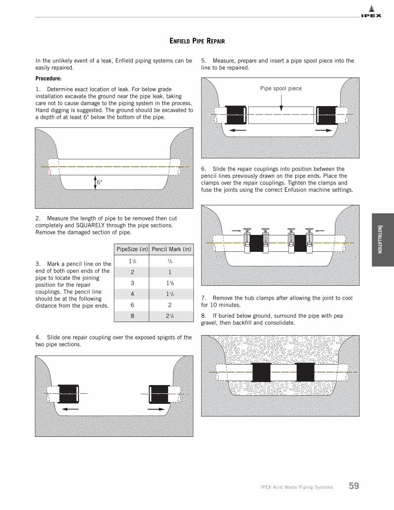
INSTALLATION
59IPEX Acid Waste Piping Systems
ENFIELD PIPE REPAIR
In the unlikely event of a leak, Enfield piping systems can beeasily repaired.
Procedure:
1. Determine exact location of leak. For below gradeinstallation excavate the ground near the pipe leak, takingcare not to cause damage to the piping system in the process.Hand digging is suggested. The ground should be excavated toa depth of at least 6" below the bottom of the pipe.
2. Measure the length of pipe to be removed then cutcompletely and SQUARELY through the pipe sections.Remove the damaged section of pipe.
3. Mark a pencil line on theend of both open ends of thepipe to locate the joiningposition for the repaircouplings. The pencil lineshould be at the followingdistance from the pipe ends.
4. Slide one repair coupling over the exposed spigots of thetwo pipe sections.
5. Measure, prepare and insert a pipe spool piece into theline to be repaired.
6. Slide the repair couplings into position between thepencil lines previously drawn on the pipe ends. Place theclamps over the repair couplings. Tighten the clamps andfuse the joints using the correct Enfusion machine settings.
7. Remove the hub clamps after allowing the joint to coolfor 10 minutes.
8. If buried below ground, surround the pipe with peagravel, then backfill and consolidate.
6"
Pipe spool piece
PipeSize (in) Pencil Mark (in)
11/2 3/4
2 1
3 13/8
4 11/2
6 2
8 21/4
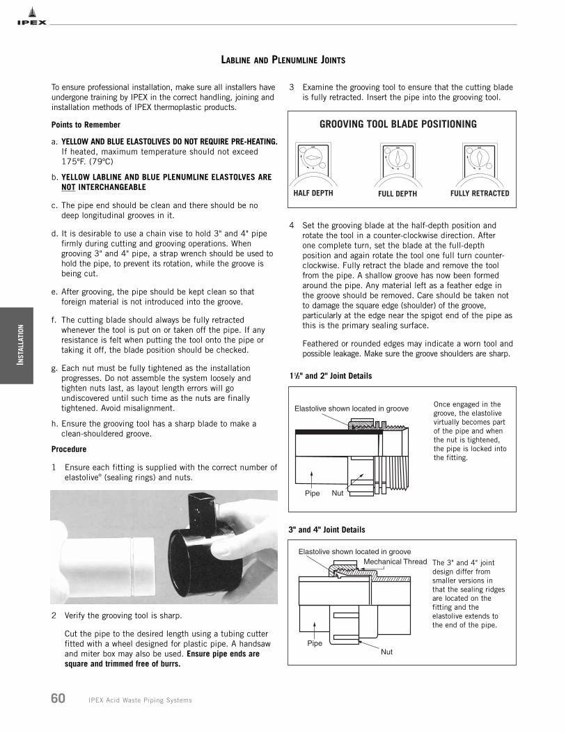
INST
ALLA
TION
60 IPEX Acid Waste Piping Systems
LABLINE AND PLENUMLINE JOINTS
To ensure professional installation, make sure all installers haveundergone training by IPEX in the correct handling, joining andinstallation methods of IPEX thermoplastic products.
Points to Remember
a. YELLOW AND BLUE ELASTOLIVES DO NOT REQUIRE PRE-HEATING.If heated, maximum temperature should not exceed 175ºF. (79ºC)
b. YELLOW LABLINE AND BLUE PLENUMLINE ELASTOLVES ARE NOT INTERCHANGEABLE
c. The pipe end should be clean and there should be no deep longitudinal grooves in it.
d. It is desirable to use a chain vise to hold 3" and 4" pipe firmly during cutting and grooving operations. When grooving 3" and 4" pipe, a strap wrench should be used to hold the pipe, to prevent its rotation, while the groove is being cut.
e. After grooving, the pipe should be kept clean so that foreign material is not introduced into the groove.
f. The cutting blade should always be fully retracted whenever the tool is put on or taken off the pipe. If any resistance is felt when putting the tool onto the pipe or taking it off, the blade position should be checked.
g. Each nut must be fully tightened as the installation progresses. Do not assemble the system loosely and tighten nuts last, as layout length errors will go undiscovered until such time as the nuts are finally tightened. Avoid misalignment.
h. Ensure the grooving tool has a sharp blade to make a clean-shouldered groove.
Procedure
1 Ensure each fitting is supplied with the correct number of elastolive® (sealing rings) and nuts.
2 Verify the grooving tool is sharp.
Cut the pipe to the desired length using a tubing cutter fitted with a wheel designed for plastic pipe. A handsaw and miter box may also be used. Ensure pipe ends are square and trimmed free of burrs.
3 Examine the grooving tool to ensure that the cutting bladeis fully retracted. Insert the pipe into the grooving tool.
4 Set the grooving blade at the half-depth position and rotate the tool in a counter-clockwise direction. After one complete turn, set the blade at the full-depth position and again rotate the tool one full turn counter- clockwise. Fully retract the blade and remove the tool from the pipe. A shallow groove has now been formed around the pipe. Any material left as a feather edge in the groove should be removed. Care should be taken not to damage the square edge (shoulder) of the groove, particularly at the edge near the spigot end of the pipe as this is the primary sealing surface.
Feathered or rounded edges may indicate a worn tool andpossible leakage. Make sure the groove shoulders are sharp.
OUT
IN
HALF DEPTH
OUT
IN
FULL DEPTH
OUT
IN
FULLY RETRACTED
GROOVING TOOL BLADE POSITIONING
11/2" and 2" Joint Details
Once engaged in thegroove, the elastolivevirtually becomes partof the pipe and whenthe nut is tightened,the pipe is locked intothe fitting.
3" and 4" Joint Details
The 3" and 4" jointdesign differ fromsmaller versions inthat the sealing ridgesare located on thefitting and theelastolive extends tothe end of the pipe.
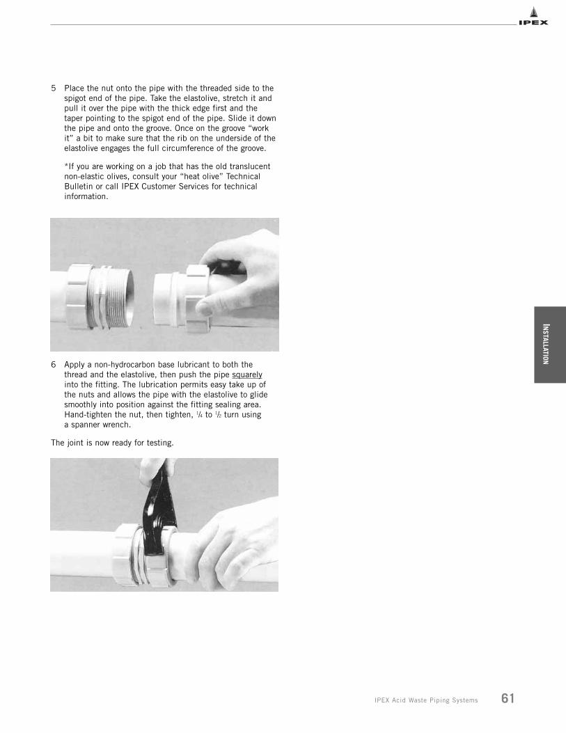
INSTALLATION
61IPEX Acid Waste Piping Systems
5 Place the nut onto the pipe with the threaded side to the spigot end of the pipe. Take the elastolive, stretch it andpull it over the pipe with the thick edge first and thetaper pointing to the spigot end of the pipe. Slide it downthe pipe and onto the groove. Once on the groove “workit” a bit to make sure that the rib on the underside of theelastolive engages the full circumference of the groove.
*If you are working on a job that has the old translucent non-elastic olives, consult your “heat olive” Technical Bulletin or call IPEX Customer Services for technical information.
6 Apply a non-hydrocarbon base lubricant to both the thread and the elastolive, then push the pipe squarelyinto the fitting. The lubrication permits easy take up of the nuts and allows the pipe with the elastolive to glide smoothly into position against the fitting sealing area. Hand-tighten the nut, then tighten, 1/4 to 1/2 turn using a spanner wrench.
The joint is now ready for testing.

INST
ALLA
TION
62 IPEX Acid Waste Piping Systems
LABLINE AND PLENUMLINE TESTING
The purpose of a site pressure test is to establish that all joints have been correctly made.
Hydro test in accordance with local plumbing code or with authority having jurisdiction or with a maximum of 10 ft of headpressure. After making the first 20 or 30 joints, it is recommended that a test be applied to prove that the joint-makingtechnique is satisfactory. If a leak is discovered, follow the appropriate procedure below.
Hydrostatic testing of the joints can be performed immediately after the final joint has been completed. The low pressuretesting procedure detailed below should be strictly followed.
1. Fully inspect the installed piping for evidence of mechanical abuse and suspect joints.
2. Split the system into convenient test sections, not exceeding 1,000 feet. The piping should be capped off with an expandable plug at the end of the pipe section to be tested.
3. Prior to starting the test in below grade applications, straight lengths of pipe should be backfilled between fittings that are tested.
4. Slowly fill the pipe section with water, taking care to evaluate all trapped air in the process. Use air release valves in any high spots in the system. Do not pressurizeat this stage.
5. Leave the pipe for at least one hour to allow an equilibrium temperature to be achieved.
6. Visually check the system for leaks.
7. Pressurize the system to a suggested maximum of 10 feet of head by means of a standard 10' standing water test using a 10' vertical riser, or a low-pressure hand pump.
8. Leave the line at 10 of feet head for a period of 2 hours,during which time the water level should not change (standing water test), nor should the pressure gauge reading change (hand pump test).
9. If there is a significant drop in pressure, or extended times are required to achieve the desired pressure, eitherjoint leakage has occurred or air is still entrapped in the line. In this event inspect for joint leaks. If none are found, check for entrapped air – these air pockets must be removed prior to continuing the test.
10. If joints are leaking, tighten the nut 1/8 to 1/4 turn and wipe the fitting to remove excess water. This should normally cure the problem. If it does not, then the grooving or setting of the elastolive should be investigated. Drain the system and undo the suspect fitting. Test first that the elastolive feels tight on the pipe by attempting to turn it with reasonable pressure such as you might use to unscrew the cap of a bottle. The elastolive should not easily move around the pipe. Ifit does, it should be replaced. If the elastolive is tight, examine it, particularly at the front, for signs of bad grooving or shavings between the elastolive and the groove. If the front edge of the groove is damaged, the joint must be re-made and the piece of pipe replaced. When examining a leaking 3" or 4" joint, particular attention should be paid to possible misalignment, as this is the most likely cause of such a leak. Make sure any misalignment is corrected before re-testing.
11. Repeat the 10 feet head test after repairing any leaking joints, following the procedure described above.
• NEVER use compressed air or gas in Enfield, Labline, or Plenumline pipes, fittings, or accessories.
• NEVER test Enfield, Labline, or Plenumline systems with compressed air or gas, or air-over-water boosters.
• ONLY use Enfield, Labline, or Plenumline systems for approved chemicals.
Use of compressed air or gas in PP or PVDF pipe andfittings can result in explosive failures and cause severeinjury or death.
WARNING
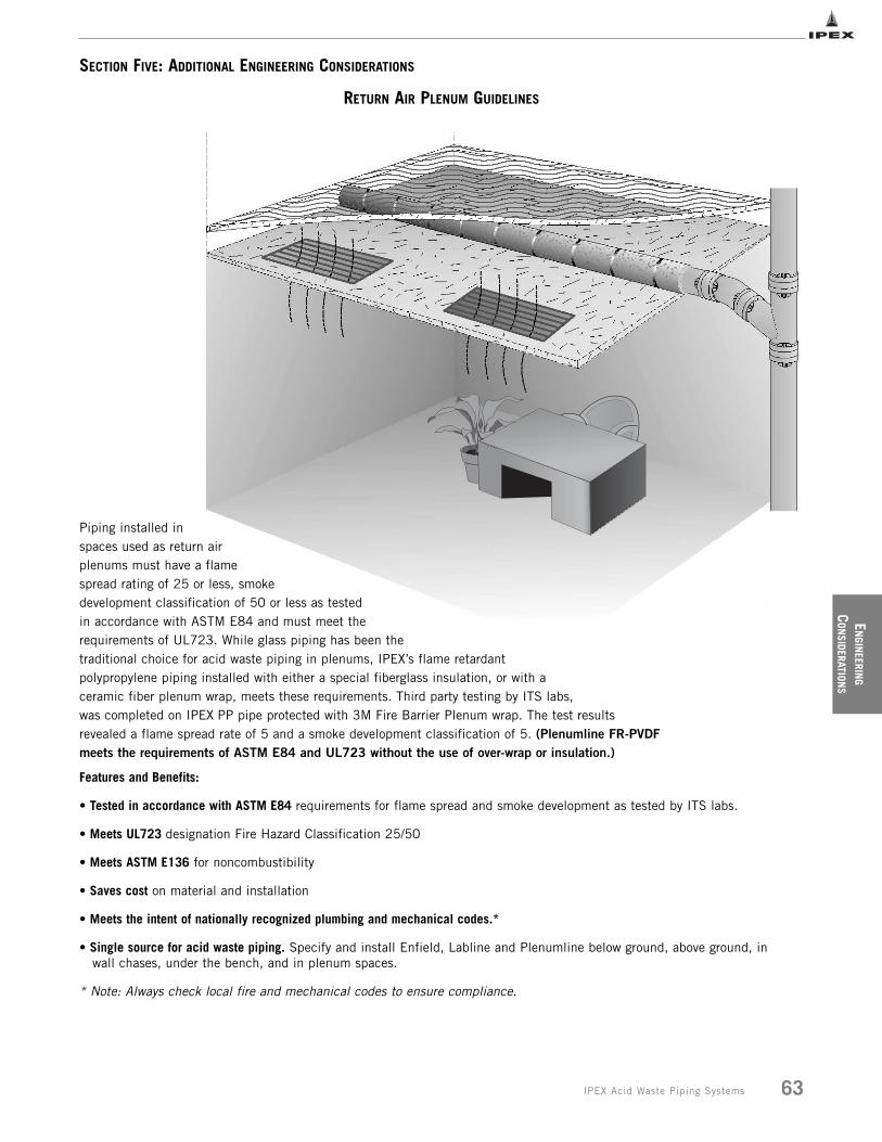
SECTION FIVE: ADDITIONAL ENGINEERING CONSIDERATIONS
Piping installed inspaces used as return airplenums must have a flamespread rating of 25 or less, smokedevelopment classification of 50 or less as testedin accordance with ASTM E84 and must meet therequirements of UL723. While glass piping has been thetraditional choice for acid waste piping in plenums, IPEX’s flame retardantpolypropylene piping installed with either a special fiberglass insulation, or with aceramic fiber plenum wrap, meets these requirements. Third party testing by ITS labs,was completed on IPEX PP pipe protected with 3M Fire Barrier Plenum wrap. The test resultsrevealed a flame spread rate of 5 and a smoke development classification of 5. (Plenumline FR-PVDFmeets the requirements of ASTM E84 and UL723 without the use of over-wrap or insulation.)
Features and Benefits:
• Tested in accordance with ASTM E84 requirements for flame spread and smoke development as tested by ITS labs.
• Meets UL723 designation Fire Hazard Classification 25/50
• Meets ASTM E136 for noncombustibility
• Saves cost on material and installation
• Meets the intent of nationally recognized plumbing and mechanical codes.*
• Single source for acid waste piping. Specify and install Enfield, Labline and Plenumline below ground, above ground, in wall chases, under the bench, and in plenum spaces.
* Note: Always check local fire and mechanical codes to ensure compliance.
EN
GINEERIN
G
CON
SIDERATIONS
RETURN AIR PLENUM GUIDELINES
63IPEX Acid Waste Piping Systems
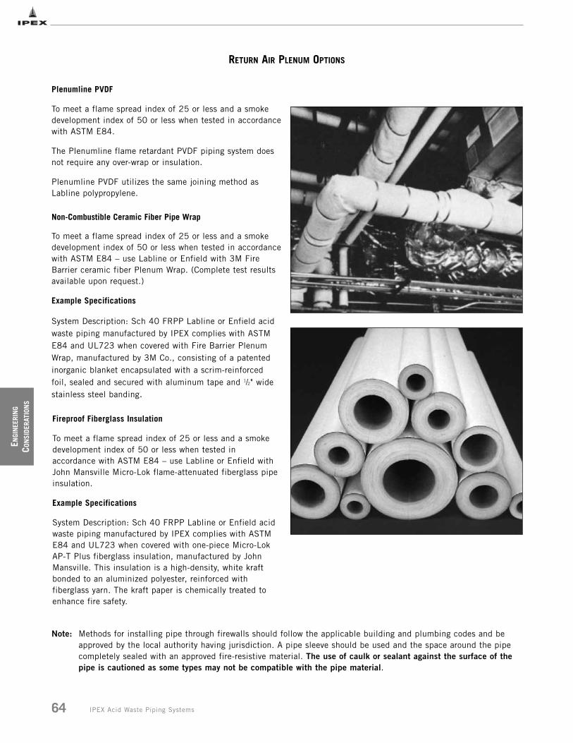
ENGI
NEE
RIN
G
CON
SIDE
RATI
ONS
64 IPEX Acid Waste Piping Systems
RETURN AIR PLENUM OPTIONS
Fireproof Fiberglass Insulation
To meet a flame spread index of 25 or less and a smokedevelopment index of 50 or less when tested inaccordance with ASTM E84 – use Labline or Enfield withJohn Mansville Micro-Lok flame-attenuated fiberglass pipeinsulation.
Example Specifications
System Description: Sch 40 FRPP Labline or Enfield acidwaste piping manufactured by IPEX complies with ASTME84 and UL723 when covered with one-piece Micro-LokAP-T Plus fiberglass insulation, manufactured by JohnMansville. This insulation is a high-density, white kraftbonded to an aluminized polyester, reinforced withfiberglass yarn. The kraft paper is chemically treated toenhance fire safety.
Plenumline PVDF
To meet a flame spread index of 25 or less and a smokedevelopment index of 50 or less when tested in accordancewith ASTM E84.
The Plenumline flame retardant PVDF piping system doesnot require any over-wrap or insulation.
Plenumline PVDF utilizes the same joining method asLabline polypropylene.
Non-Combustible Ceramic Fiber Pipe Wrap
To meet a flame spread index of 25 or less and a smokedevelopment index of 50 or less when tested in accordancewith ASTM E84 – use Labline or Enfield with 3M FireBarrier ceramic fiber Plenum Wrap. (Complete test resultsavailable upon request.)
Example Specifications
System Description: Sch 40 FRPP Labline or Enfield acidwaste piping manufactured by IPEX complies with ASTME84 and UL723 when covered with Fire Barrier PlenumWrap, manufactured by 3M Co., consisting of a patentedinorganic blanket encapsulated with a scrim-reinforcedfoil, sealed and secured with aluminum tape and 1/2" widestainless steel banding.
Note: Methods for installing pipe through firewalls should follow the applicable building and plumbing codes and beapproved by the local authority having jurisdiction. A pipe sleeve should be used and the space around the pipecompletely sealed with an approved fire-resistive material. The use of caulk or sealant against the surface of thepipe is cautioned as some types may not be compatible with the pipe material.

EN
GINEERIN
G
CON
SIDERATIONS
65IPEX Acid Waste Piping Systems
ADAPTING TO OTHER DRAINLINE MATERIALS
COMPRESSION COUPLING-Supplied by Glass Vendor
BEADED GLASS PIPE
ENFIELD GLASSADAPTER #L45 SERIES
IPEX ACID WASTE PIPE
(L45 SERIES)
COMPRESSION COUPLING
BEADED GLASS DRAINLINE IPEX ACID WASTE PIPE
LABLINE ADAPTER TO GLASS (W45 SERIES)
CAST IRON MJ COUPLING
SILICON IRONDRAINLINE
IPEX ACID WASTE PIPE
ENFIELD NO HUB ADAPTER (L46 SERIES) LABLINE NO HUB ADAPTER
CAST IRON MJ COUPLING
SILICON IRON DRAINLINE IPEX ACID WASTE PIPE
(W46 SERIES)
METAL DRAINLINE IPEX ACID WASTE PIPE
ENFIELD FEMALE ADAPTER (L15 SERIES)
METAL DRAINLINE IPEX ACID WASTE PIPE
LABLINE OR PLENUMLINE FEMALE ADAPTER (W15 / W15P SERIES)
PVC POLYETHYLENEOR POLYPROPYLENEDRAINLINES
IPEX ACID WASTE PIPE
LABLINE OR PLENUMLINE COUPLING (W16 / W16P SERIES)
IPEX ACID WASTE PIPE
POURED LEAD OR CAULKING CEMENT
PACKINGMETAL PIPE BELL
The methods depicted below are recommended only as a means of adapting to other drainline materials. Enfield and Lablinecomponents are dimensionally matched to assure installation success. Do not install a system of mixed brands.
Use an Enfield glass adapter and a compression coupling available from glass drainline vendors.
Use a Labline glass adapter and compression coupling available from glass drainline vendors.
Use an Enfield adapter and an MJ Cast Iron coupling available from silicon iron pipe manufacturer.
Use a Labline No Hub adapter and a Cast Iron MJcoupling available from silicon iron pipe manufacturer.
1. Roughen or score pipe end with suitable tool or coarse file to provide a “key”.
2. Insert Enfield pipe until it bottoms at the stop.3. Pack hub half full with asbestos rope, or acid
resistant oakum.4. Caulk with hot lead, lead wool or caulking cement.
Use an Enfield Female adapter and Teflon tape. Use a Labline Female adapter and Teflon tape.
Groove both sections and use Labline coupling.
Glass
Silicon Iron
Plastic Pipe
Metal Pipe-Threaded
Metal Pipe-Caulked
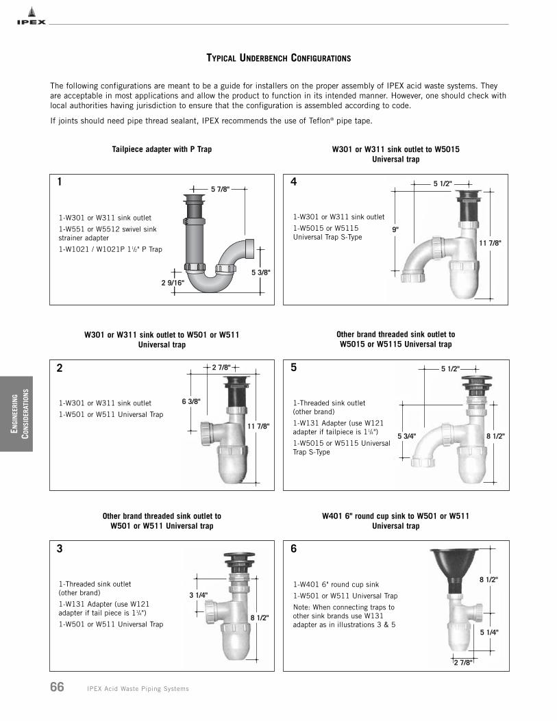
ENGI
NEE
RIN
G
CON
SIDE
RATI
ONS
66 IPEX Acid Waste Piping Systems
TYPICAL UNDERBENCH CONFIGURATIONS
2 7/8"
5 1/4"
8 1/2"
W401 6" round cup sink to W501 or W511 Universal trap
1-W401 6" round cup sink
1-W501 or W511 Universal Trap
Note: When connecting traps toother sink brands use W131adapter as in illustrations 3 & 5
5 1/2"
9"
11 7/8"
8 1/2"
3 1/4"
2 7/8"
6 3/8"
11 7/8"
5 1/2"
5 3/4" 8 1/2"
W301 or W311 sink outlet to W501 or W511 Universal trap
Other brand threaded sink outlet to W501 or W511 Universal trap
W301 or W311 sink outlet to W5015 Universal trap
Other brand threaded sink outlet to W5015 or W5115 Universal trap
1-W301 or W311 sink outlet
1-W501 or W511 Universal Trap
1-Threaded sink outlet(other brand)
1-W131 Adapter (use W121adapter if tail piece is 11/4")
1-W501 or W511 Universal Trap
1-W301 or W311 sink outlet
1-W5015 or W5115Universal Trap S-Type
1-Threaded sink outlet (other brand)
1-W131 Adapter (use W121adapter if tailpiece is 11/4")
1-W5015 or W5115 UniversalTrap S-Type
5 3/8"
5 7/8"
2 9/16"
Tailpiece adapter with P Trap
1-W301 or W311 sink outlet
1-W551 or W5512 swivel sinkstrainer adapter
1-W1021 / W1021P 11/2" P Trap
1
2
4
3
5
6
The following configurations are meant to be a guide for installers on the proper assembly of IPEX acid waste systems. Theyare acceptable in most applications and allow the product to function in its intended manner. However, one should check withlocal authorities having jurisdiction to ensure that the configuration is assembled according to code.
If joints should need pipe thread sealant, IPEX recommends the use of Teflon® pipe tape.
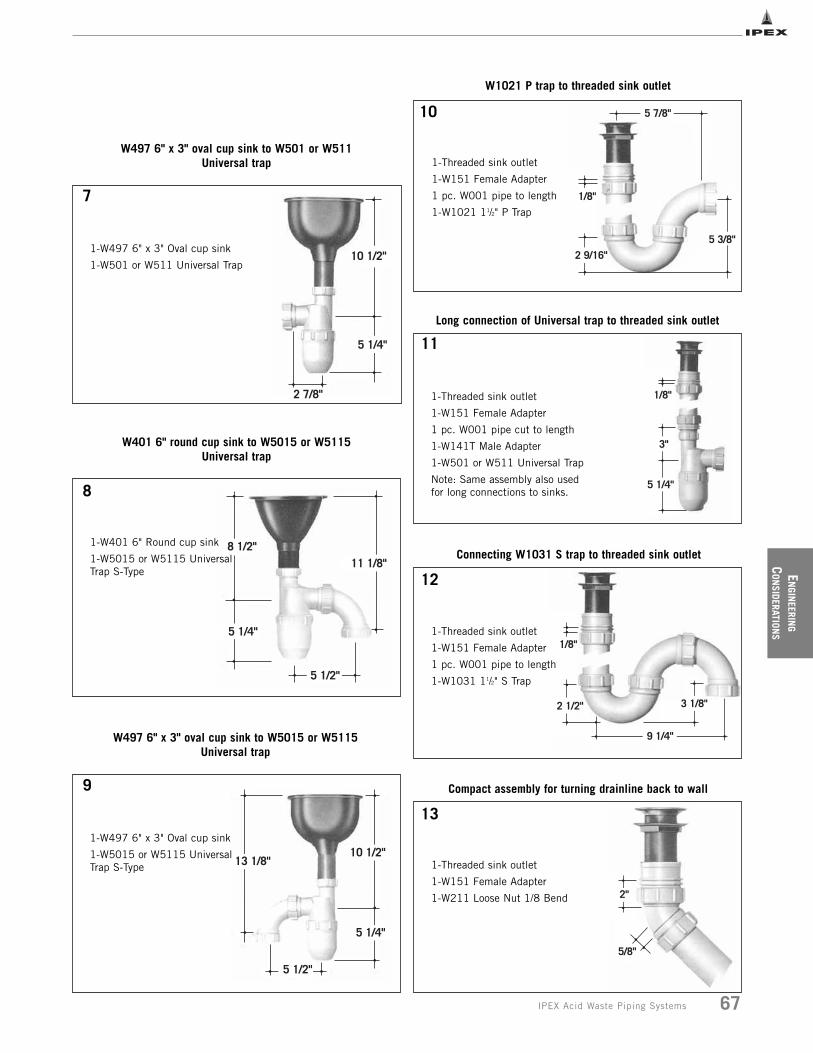
EN
GINEERIN
G
CON
SIDERATIONS
IPEX Acid Waste Piping Systems
5 7/8"
5 3/8"2 9/16"
1/8"
2"
5/8"
10 1/2"
5 1/4"
5 1/2"
13 1/8"
1/8"
2 1/2"
9 1/4"
3 1/8"
11 1/8"
5 1/2"
5 1/4"
8 1/2"
5 1/4"
3"
1/8"
W401 6" round cup sink to W5015 or W5115 Universal trap
W497 6" x 3" oval cup sink to W5015 or W5115 Universal trap
W1021 P trap to threaded sink outlet
Long connection of Universal trap to threaded sink outlet
Compact assembly for turning drainline back to wall
1-W401 6" Round cup sink
1-W5015 or W5115 UniversalTrap S-Type
1-W497 6" x 3" Oval cup sink
1-W5015 or W5115 UniversalTrap S-Type
1-Threaded sink outlet
1-W151 Female Adapter
1 pc. W001 pipe to length
1-W1021 11/2" P Trap
1-Threaded sink outlet
1-W151 Female Adapter
1 pc. W001 pipe cut to length
1-W141T Male Adapter
1-W501 or W511 Universal Trap
Note: Same assembly also usedfor long connections to sinks.
1-Threaded sink outlet
1-W151 Female Adapter
1 pc. W001 pipe to length
1-W1031 11/2" S Trap
1-Threaded sink outlet
1-W151 Female Adapter
1-W211 Loose Nut 1/8 Bend
10 1/2"
5 1/4"
2 7/8"
W497 6" x 3" oval cup sink to W501 or W511 Universal trap
1-W497 6" x 3" Oval cup sink
1-W501 or W511 Universal Trap
10
7
8
9
11
12
13
Connecting W1031 S trap to threaded sink outlet
67

NOTES
______________________________________________________
______________________________________________________
______________________________________________________
______________________________________________________
______________________________________________________
______________________________________________________
______________________________________________________
______________________________________________________
______________________________________________________
______________________________________________________
______________________________________________________
______________________________________________________
______________________________________________________
______________________________________________________
______________________________________________________
______________________________________________________
______________________________________________________
______________________________________________________
______________________________________________________
______________________________________________________
______________________________________________________
______________________________________________________
______________________________________________________
______________________________________________________
______________________________________________________
______________________________________________________
______________________________________________________
______________________________________________________
______________________________________________________
______________________________________________________
______________________________________________________
______________________________________________________
______________________________________________________
______________________________________________________
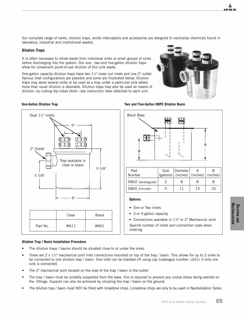
DILU
TIONAN
D
NEU
TRALIZATION
9"
9 5/8"
8"
6 5/8"
Our complete range of tanks, dilution traps, solids interceptors and accessories are designed to neutralize chemicals found inlaboratory, industrial and institutional wastes.
Dilution Traps
It is often necessary to dilute waste from individual sinks or small groups of sinksbefore discharging into the system. Our one-, two-and five-gallon dilution trapsallow for convenient point-of-use dilution of this sink waste.
One-gallon capacity dilution traps have two 11/2" loose nut inlets and one 2" outlet.Various inlet configurations are possible and some are illustrated below. Dilutiontraps may serve several sinks or be used as a trap under a particular sink wheremore than usual dilution is desirable. Dilution traps may also be used as means ofdilution, by cutting dip tubes short__see instruction label attached to each unit.
Part No.
Clear
W611
Black
W601
Options:
• One or Two Inlets
• 2-or 5-gallon capacity
• Connections available in 11/2" or 2" Mechanical Joint
Specify number of inlets and connection sizes whenordering
Part Number
DB02
DB05
Size (gallons)
2
5
Diameter (inches)
8
11
A (inches)
8
13
B (inches)
8
10
Dual 11/2" Inlets
2" Outlet
Trap available inclear or black
Black Base
One-Gallon Dilution Trap
Dilution Trap / Basin Installation Procedure
• The dilution traps / basins should be situated close to or under the sinks.
• There are 2 x 11/2" mechanical joint inlet connections mounted on top of the trap / basin. This allows for up to 2 sinks to be connected to one dilution trap / basin. One inlet can be blanked off using cap (catalogue number: L641) if only one sink is connected.
• The 2" mechanical joint located on the side of the trap / basin is the outlet.
• The trap / basin must be suitably supported from the base, this is required to prevent any undue stress being exerted on the fittings. Support can also be achieved by situating the trap / basin on the ground.
• The dilution trap / basin must NOT be filled with limestone chips. Limestone chips are only to be used in Neutralization Tanks.
(rectangular)
(circular)
Two and Five-Gallon HDPE Dilution Basin
69IPEX Acid Waste Piping Systems
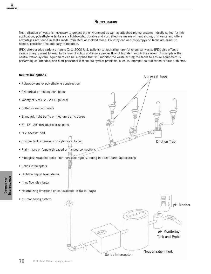
D ILU
TION
AND
NEU
TRAL
IZAT
ION
70 IPEX Acid Waste Piping Systems
Solids InterceptorNeutralization Tank
pH Monitoring
Tank and Probe
NEUTRALIZATION
Neutralization of waste is necessary to protect the environment as well as attached piping systems. Ideally suited for thisapplication, polyethylene tanks are a lightweight, durable and cost effective means of neutralizing this waste and offersadvantages not found in tanks made from steel or molded stone. Polyethylene and polypropylene tanks are easier tohandle, corrosion-free and easy to maintain.
IPEX offers a wide variety of tanks (2 to 2000 U.S. gallons) to neutralize harmful chemical waste. IPEX also offers avariety of equipment to keep tanks free of solids and insure proper flow of liquids through the system. To complete theneutralization system, equipment can be supplied that will monitor the waste exiting the tanks to ensure equipment isperforming as intended, and alert personnel if there are system problems, such as improper neutralization or flow problems.
Neutratank options:
• Polypropylene or polyethylene construction
• Cylindrical or rectangular shapes
• Variety of sizes (2 - 2000 gallons)
• Bolted or welded covers
• Standard, light traffic or medium traffic covers
• 8", 18", 25" threaded access ports
• “EZ Access” port
• Custom tank extensions on cylindrical tanks
• Plain, male or female threaded or flanged connections
• Fiberglass wrapped tanks - for increased rigidity, aiding in direct burial applications
• Solids interceptors
• High/low liquid level alarms
• Inlet flow distributor
• Neutralizing limestone chips (available in 50 lb. bags)
• pH monitoring system
Universal Traps
Dilution Trap
pH Monitor
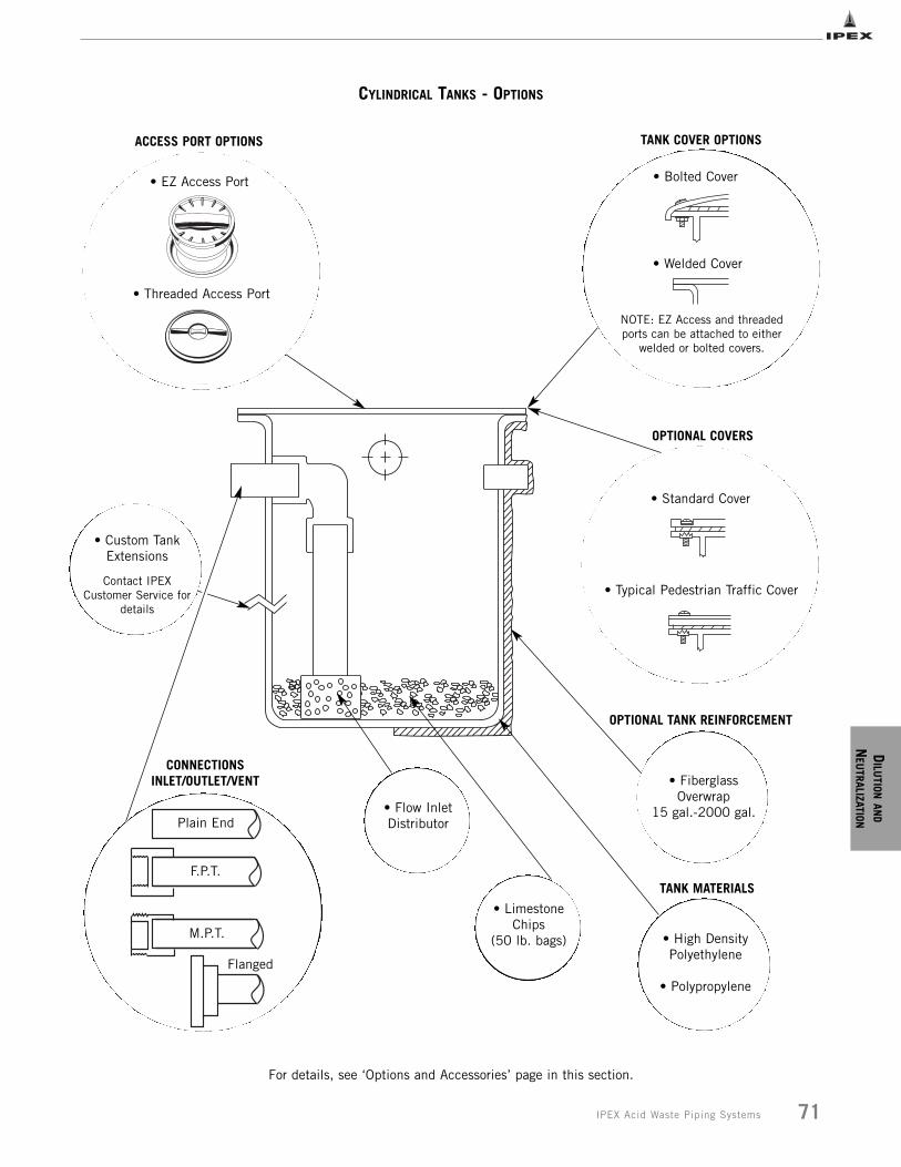
DILU
TIONAN
D
NEU
TRALIZATION
71IPEX Acid Waste Piping Systems
CYLINDRICAL TANKS - OPTIONS
TANK COVER OPTIONS
• Bolted Cover
• Welded Cover
NOTE: EZ Access and threadedports can be attached to either
welded or bolted covers.
• FiberglassOverwrap
15 gal.-2000 gal.• Flow InletDistributor
• High DensityPolyethylene
• Polypropylene
• LimestoneChips
(50 lb. bags)
OPTIONAL COVERS
OPTIONAL TANK REINFORCEMENT
TANK MATERIALS
• Standard Cover
• Typical Pedestrian Traffic Cover
• Custom TankExtensions
Contact IPEXCustomer Service for
details
ACCESS PORT OPTIONS
• EZ Access Port
• Threaded Access Port
Plain End
F.P.T.
M.P.T.
Flanged
CONNECTIONS INLET/OUTLET/VENT
For details, see ‘Options and Accessories’ page in this section.
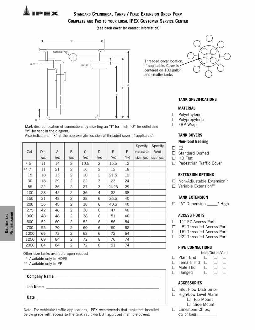
D ILU
TION
AND
NEU
TRAL
IZAT
ION
STANDARD CYLINDRICAL TANKS / FIXED EXTENSION ORDER FORM
COMPLETE AND FAX TO YOUR LOCAL IPEX CUSTOMER SERVICE CENTER
(see back cover for contact information)
E
AF
C
B
D
Inlet
Optional Vent
Outlet
Mark desired location of connections by inserting an “I” for inlet, “O” for outlet and“V” for vent in the diagram.Also indicate an “X” at the approximate location of threaded cover (if applicable).
Company Name _________________________________________________
Job Name ______________________________________________________
Date __________________________________________________________
Threaded cover location,if applicable. Cover iscentered on 100 gallonand smaller tanks
Gal.
5
7
15
30
55
100
150
200
275
360
500
700
1000
1250
2000
Dia.
(in)
11
11
18
18
22
28
31
36
42
48
52
55
66
69
84
A
(in)
14
21
15
29
36
42
48
48
48
48
60
70
72
84
84
B
(in)
2
2
2
2
2
2
2
2
2
2
2
2
2
2
2
C
(in)
10.5
16
10
22
27
36
38
38
38
38
52
60
62
72
72
D
(in)
2
2
2
3
3
4
6
6
6
6
6
6
6
8
8
E
(in)
15.5
12
21.5
23
24.25
32
36.5
40.5
47
51
56
60
72
76
91
F
(in)
12
18
12
24
29
38
40
40
40
40
54
62
64
74
74
Specify
Inlet/Outlet
size (in)
Specify
Vent
size (in)
Other size tanks available upon request* Available only in HDPE
** Available only in PP
*
PolyethylenePolypropylene FRP Wrap
Non-load Bearing
EZStandard DomedHD FlatPedestrian Traffic Cover
TANK COVERS
MATERIAL
ACCESS PORTS
11" EZ Access Port8" Threaded Access Port
16" Threaded Access Port22" Threaded Access Port
TANK EXTENSION
“A” Dimension _____" High
PIPE CONNECTIONS
Plain EndFemale ThdMale ThdFlanged
Inlet/Outlet/Vent
ACCESSORIES
Inlet Flow DistributorHigh/Low Level Alarm
Top MountSide Mount
Limestone Chips, qty of bags __________
TANK SPECIFICATIONS
Note: For vehicular traffic applications, IPEX recommends that tanks are installedbelow grade with access to the tank vault via DOT approved manhole covers.
EXTENSION OPTIONS
Non-Adjustable ExtensionTM
Variable ExtensionTM
**
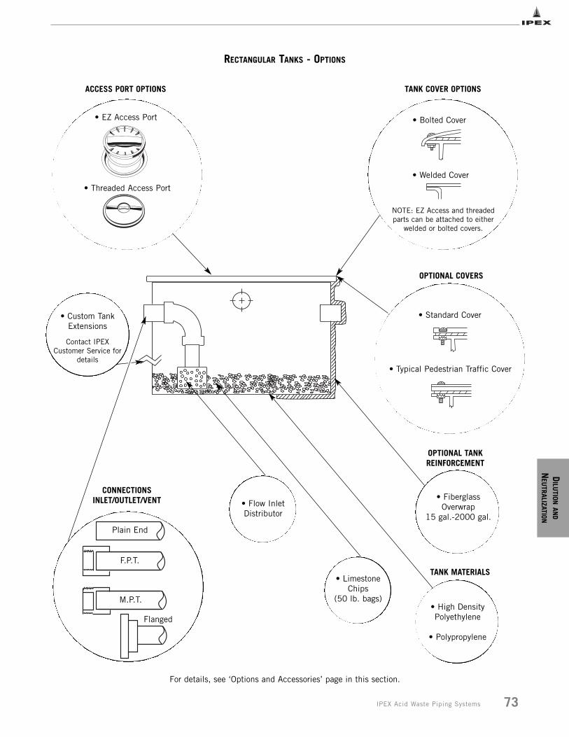
DILU
TIONAN
D
NEU
TRALIZATION
73IPEX Acid Waste Piping Systems
RECTANGULAR TANKS - OPTIONS
ACCESS PORT OPTIONS
• EZ Access Port
• Threaded Access Port
• Bolted Cover
• Welded Cover
NOTE: EZ Access and threadedparts can be attached to either
welded or bolted covers.
• Custom TankExtensions
Contact IPEXCustomer Service for
details
• FiberglassOverwrap
15 gal.-2000 gal.
• Flow InletDistributor
• High DensityPolyethylene
• Polypropylene
• LimestoneChips
(50 lb. bags)
OPTIONAL COVERS
OPTIONAL TANKREINFORCEMENT
TANK MATERIALS
CONNECTIONS INLET/OUTLET/VENT
Plain End
F.P.T.
M.P.T.
Flanged
• Standard Cover
• Typical Pedestrian Traffic Cover
TANK COVER OPTIONS
For details, see ‘Options and Accessories’ page in this section.
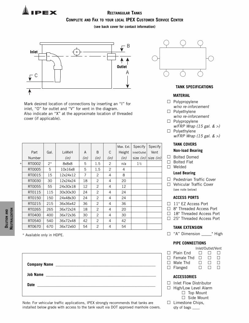
D ILU
TION
AND
NEU
TRAL
IZAT
ION
RECTANGULAR TANKS
COMPLETE AND FAX TO YOUR LOCAL IPEX CUSTOMER SERVICE CENTER
(see back cover for contact information)
A
B
C
Part
Number
RT0002
RT0005
RT0015
RT0030
RT0055
RT0115
RT0150
RT0215
RT0265
RT0400
RT0540
RT0670
Gal.
2*
5
15
30
55
115
150
215
265
400
540
670
LxWxH
(in)
8x8x8
10x16x8
12x24x12
12x24x24
24x30x18
30x30x30
24x48x30
36x36x42
36x72x24
36x72x36
36x72x48
36x72x60
A
(in)
5
5
7
18
12
24
24
36
18
30
42
54
B
(in)
1.5
1.5
2
2
2
2
2
2
2
2
2
2
C
(in)
2
2
4
4
4
4
4
4
4
4
4
4
Max. Ext.
Height
(in)
n/a
4
8
20
12
24
24
36
20
30
42
54
Specify
Inlet/Outlet
size (in)
11/2
Specify
Vent
size (in)
Mark desired location of connections by inserting an “I” forinlet, “O” for outlet and “V” for vent in the diagram.Also indicate an “X” at the approximate location of threadedcover (if applicable).
Inlet
Outlet
* Available only in HDPE.
*
Company Name _________________________________________________
Job Name ______________________________________________________
Date __________________________________________________________
Note: For vehicular traffic applications, IPEX strongly recommends that tanks areinstalled below grade with access to the tank vault via DOT approved manhole covers.
Polypropylene w/no re-inforcementPolyethylene w/no re-inforcementPolypropylene w/FRP Wrap (15 gal. & >)Polyethylene w/FRP Wrap (15 gal. & >)
Non-load Bearing
Bolted DomedBolted FlatWelded
Load Bearing
Pedestrian Traffic CoverVehicular Traffic Cover(see note below)
TANK COVERS
MATERIAL
ACCESS PORTS
11" EZ Access Port8" Threaded Access Port18" Threaded Access Port25" Threaded Access Port
TANK EXTENSION
“A” Dimension _____" High
PIPE CONNECTIONS
Plain EndFemale ThdMale ThdFlanged
Inlet/Outlet/Vent
ACCESSORIES
Inlet Flow DistributorHigh/Low Level Alarm
Top MountSide Mount
Limestone Chips, qty of bags ____
TANK SPECIFICATIONS
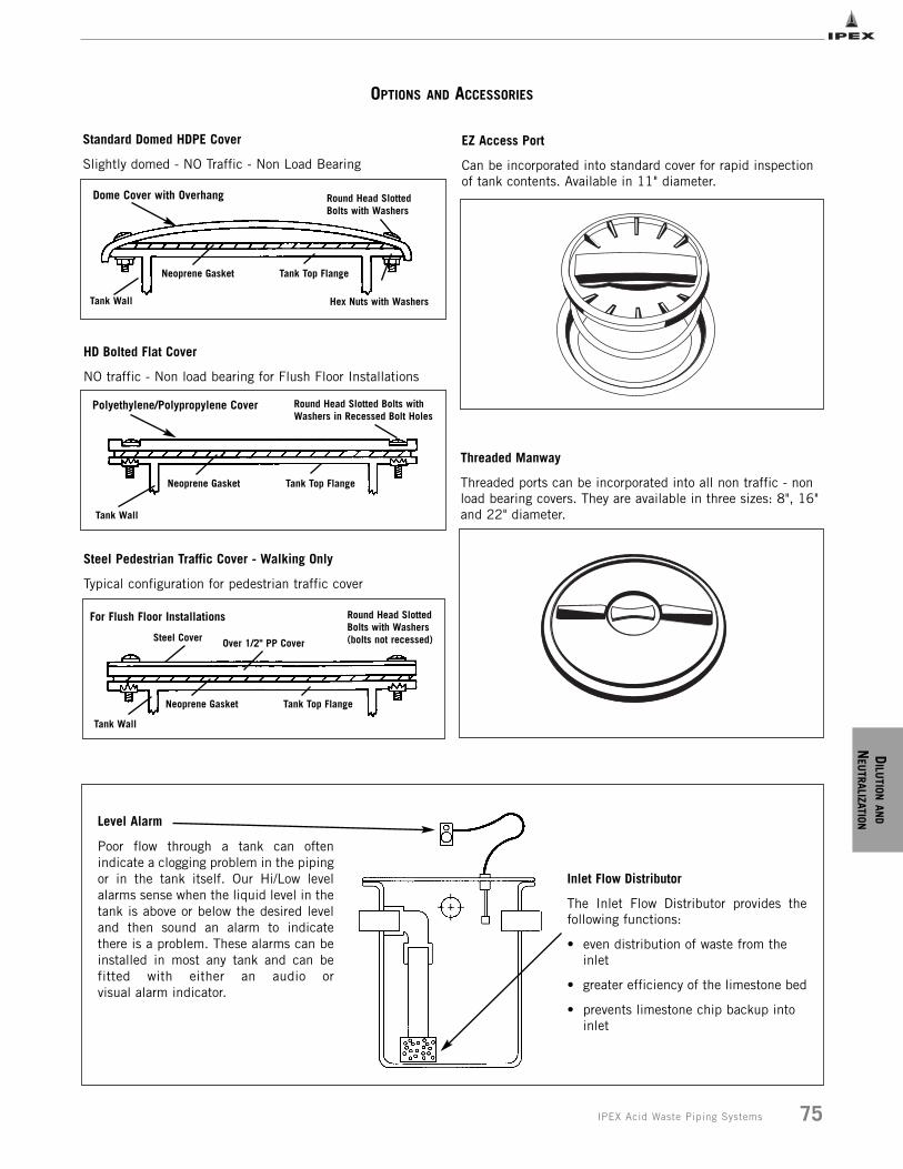
DILU
TIONAN
D
NEU
TRALIZATION
75IPEX Acid Waste Piping Systems
OPTIONS AND ACCESSORIES
Standard Domed HDPE Cover
Slightly domed - NO Traffic - Non Load Bearing
HD Bolted Flat Cover
NO traffic - Non load bearing for Flush Floor Installations
Steel Pedestrian Traffic Cover - Walking Only
Typical configuration for pedestrian traffic cover
EZ Access Port
Can be incorporated into standard cover for rapid inspectionof tank contents. Available in 11" diameter.
Threaded Manway
Threaded ports can be incorporated into all non traffic - nonload bearing covers. They are available in three sizes: 8", 16"and 22" diameter.
Level Alarm
Poor flow through a tank can oftenindicate a clogging problem in the pipingor in the tank itself. Our Hi/Low levelalarms sense when the liquid level in thetank is above or below the desired leveland then sound an alarm to indicatethere is a problem. These alarms can beinstalled in most any tank and can befitted with either an audio or visual alarm indicator.
Inlet Flow Distributor
The Inlet Flow Distributor provides thefollowing functions:
• even distribution of waste from the inlet
• greater efficiency of the limestone bed
• prevents limestone chip backup into inlet
Dome Cover with Overhang Round Head SlottedBolts with Washers
Hex Nuts with Washers
Tank Top FlangeNeoprene Gasket
Tank Wall
Polyethylene/Polypropylene Cover Round Head Slotted Bolts withWashers in Recessed Bolt Holes
Tank Top FlangeNeoprene Gasket
Tank Wall
For Flush Floor Installations Round Head SlottedBolts with Washers(bolts not recessed)Steel Cover Over 1/2" PP Cover
Tank Top FlangeNeoprene Gasket
Tank Wall
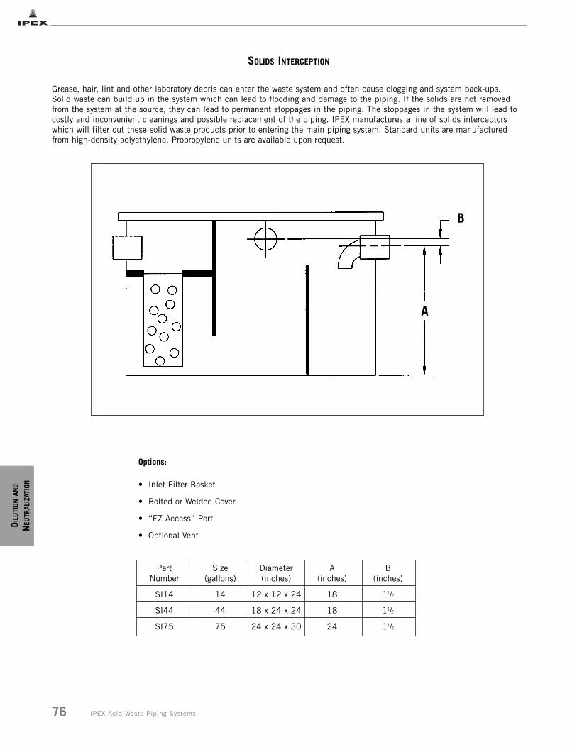
D ILU
TION
AND
NEU
TRAL
IZAT
ION
76 IPEX Acid Waste Piping Systems
SOLIDS INTERCEPTION
Grease, hair, lint and other laboratory debris can enter the waste system and often cause clogging and system back-ups.Solid waste can build up in the system which can lead to flooding and damage to the piping. If the solids are not removedfrom the system at the source, they can lead to permanent stoppages in the piping. The stoppages in the system will lead tocostly and inconvenient cleanings and possible replacement of the piping. IPEX manufactures a line of solids interceptorswhich will filter out these solid waste products prior to entering the main piping system. Standard units are manufacturedfrom high-density polyethylene. Propropylene units are available upon request.
Options:
• Inlet Filter Basket
• Bolted or Welded Cover
• “EZ Access” Port
• Optional Vent
Part Number
SI14
SI44
SI75
Size (gallons)
14
44
75
Diameter (inches)
12 x 12 x 24
18 x 24 x 24
24 x 24 x 30
A (inches)
18
18
24
B (inches)
11/2
11/2
11/2
A
B
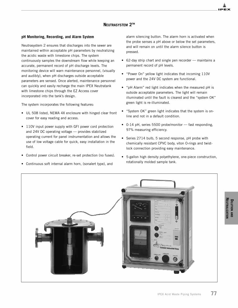
DILU
TIONAN
D
NEU
TRALIZATION
77IPEX Acid Waste Piping Systems
NEUTRASYSTEM 2TM
pH Monitoring, Recording, and Alarm System
Neutrasystem 2 ensures that discharges into the sewer aremaintained within acceptable pH parameters by neutralizingthe acidic waste with limestone chips. The systemcontinuously samples the downstream flow while keeping anaccurate, permanent record of pH discharge levels. Themonitoring device will warn maintenance personnel, (visuallyand audibly), when pH discharges outside acceptableparameters are sensed. Once alerted, maintenance personnelcan quickly and easily recharge the main IPEX Neutratankwith limestone chips through the EZ Access coverincorporated into the tank’s design.
The system incorporates the following features:
• UL 508 listed, NEMA 4X enclosure with hinged clear frontcover for easy reading and access.
• 110V input power supply with GFI power cord protection and 24V DC operating voltage __ provides stabilized operating current for panel instrumentation and allows theuse of low voltage cable for quick, easy installation in the field.
• Control power circuit breaker, re-set protection (no fuses).
• Continuous soft internal alarm horn, (sonalert type), and
alarm silencing button. The alarm horn is activated when the probe senses a pH above or below the set parameters, and will remain on until the alarm silence button is pressed.
• 62-day strip chart and single pen recorder __ maintains a permanent record of pH levels.
• “Power On” yellow light indicates that incoming 110V power and the 24V DC system are functional.
• “pH Alarm” red light indicates when the measured pH is outside acceptable parameters. The light will remain illuminated until the fault is cleared and the “system OK” green light is re-illuminated.
• “System OK” green light indicates that the system is on-line and not in a default condition.
• 0-14 pH, series 5500 probe/monitor __ fast responding, 97% measuring efficiency.
• Series 2714 bulb, 5 second response, pH probe with chemically resistant CPVC body, viton O-rings and twist-lock connection providing easy maintenance.
• 5-gallon high density polyethylene, one-piece construction,rotationally molded sample tank.
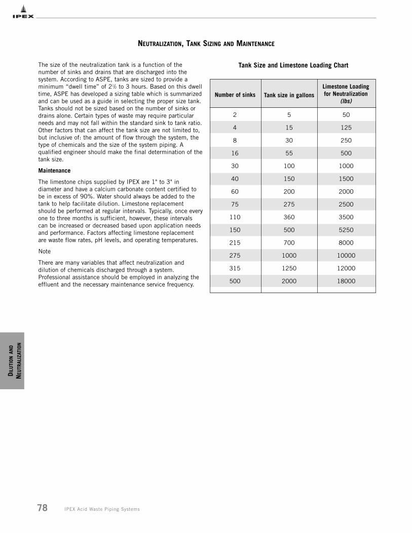
D ILU
TION
AND
NEU
TRAL
IZAT
ION
78 IPEX Acid Waste Piping Systems
NEUTRALIZATION, TANK SIZING AND MAINTENANCE
The size of the neutralization tank is a function of thenumber of sinks and drains that are discharged into thesystem. According to ASPE, tanks are sized to provide aminimum “dwell time” of 21/2 to 3 hours. Based on this dwelltime, ASPE has developed a sizing table which is summarizedand can be used as a guide in selecting the proper size tank.Tanks should not be sized based on the number of sinks ordrains alone. Certain types of waste may require particularneeds and may not fall within the standard sink to tank ratio.Other factors that can affect the tank size are not limited to,but inclusive of: the amount of flow through the system, thetype of chemicals and the size of the system piping. Aqualified engineer should make the final determination of thetank size.
Maintenance
The limestone chips supplied by IPEX are 1" to 3" indiameter and have a calcium carbonate content certified tobe in excess of 90%. Water should always be added to thetank to help facilitate dilution. Limestone replacementshould be performed at regular intervals. Typically, once everyone to three months is sufficient, however, these intervalscan be increased or decreased based upon application needsand performance. Factors affecting limestone replacementare waste flow rates, pH levels, and operating temperatures.
Note
There are many variables that affect neutralization anddilution of chemicals discharged through a system.Professional assistance should be employed in analyzing theeffluent and the necessary maintenance service frequency.
2
4
8
16
30
40
60
75
110
150
215
275
315
500
5
15
30
55
100
150
200
275
360
500
700
1000
1250
2000
Number of sinks Tank size in gallonsLimestone Loadingfor Neutralization
(lbs)
Tank Size and Limestone Loading Chart
50
125
250
500
1000
1500
2000
2500
3500
5250
8000
10000
12000
18000
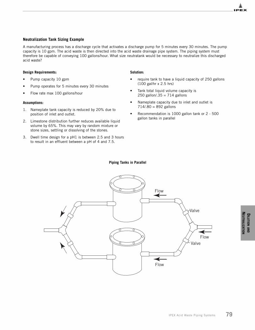
DILU
TIONAN
D
NEU
TRALIZATION
79IPEX Acid Waste Piping Systems
Neutralization Tank Sizing Example
A manufacturing process has a discharge cycle that activates a discharge pump for 5 minutes every 30 minutes. The pumpcapacity is 10 gpm. The acid waste is then directed into the acid waste drainage pipe system. The piping system musttherefore be capable of conveying 100 gallons/hour. What size neutratank would be necessary to neutralize this dischargedacid waste?
Design Requirements:
• Pump capacity 10 gpm
• Pump operates for 5 minutes every 30 minutes
• Flow rate max 100 gallons/hour
Assumptions:
1. Nameplate tank capacity is reduced by 20% due to position of inlet and outlet.
2. Limestone distribution further reduces available liquid volume by 65%. This may vary by random mixture or stone sizes, settling or dissolving of the stones.
3. Dwell time design for a pH1 is between 2.5 and 3 hours to result in an effluent between a pH of 4 and 7.5.
Solution:
• require tank to have a liquid capacity of 250 gallons(100 gal/hr x 2.5 hrs)
• Tank total liquid volume capacity is 250 gallon/.35 = 714 gallons
• Nameplate capacity due to inlet and outlet is 714/.80 = 892 gallons
• Recommendation is 1000 gallon tank or 2 - 500 gallon tanks in parallel
Flow
Flow
Flow
Valve
Valve
Piping Tanks in Parallel
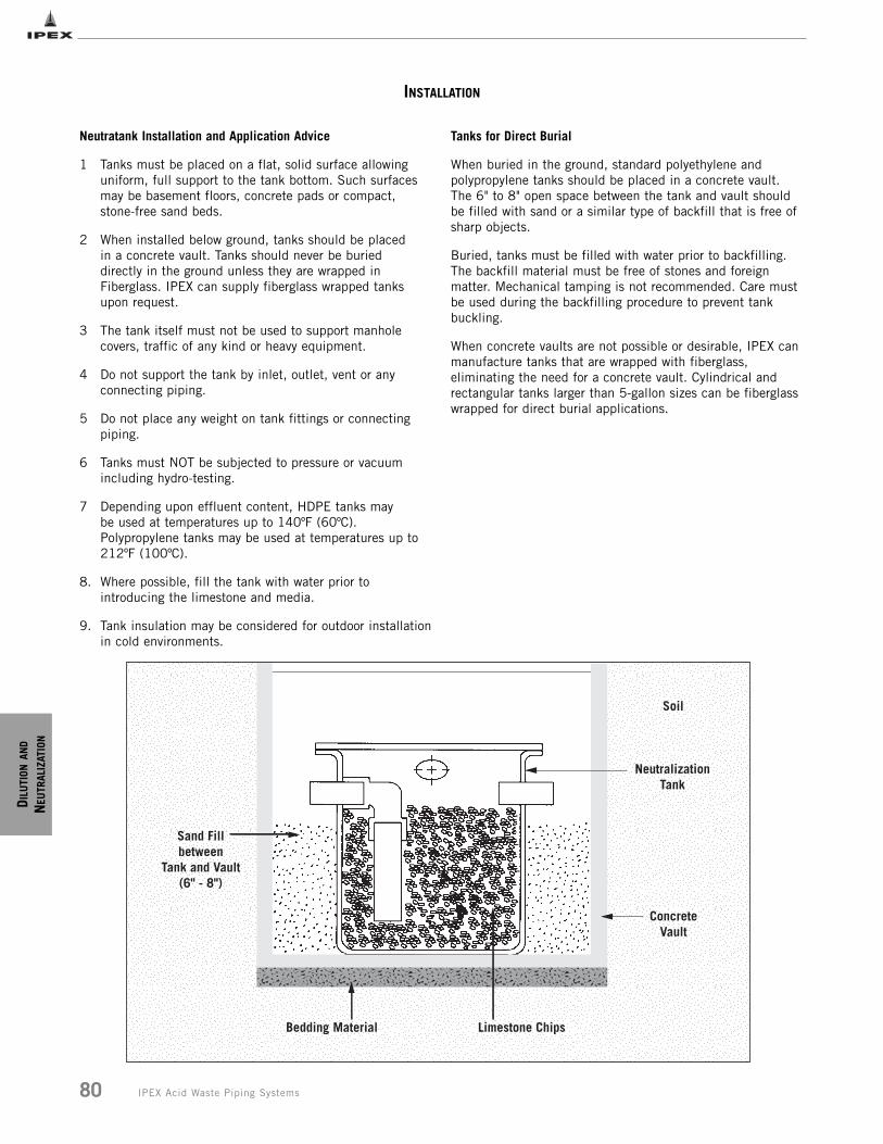
D ILU
TION
AND
NEU
TRAL
IZAT
ION
80 IPEX Acid Waste Piping Systems
INSTALLATION
Soil
NeutralizationTank
ConcreteVault
Limestone ChipsBedding Material
Sand Fillbetween
Tank and Vault(6" - 8")
Neutratank Installation and Application Advice
1 Tanks must be placed on a flat, solid surface allowing uniform, full support to the tank bottom. Such surfaces may be basement floors, concrete pads or compact, stone-free sand beds.
2 When installed below ground, tanks should be placed in a concrete vault. Tanks should never be buried directly in the ground unless they are wrapped in Fiberglass. IPEX can supply fiberglass wrapped tanks upon request.
3 The tank itself must not be used to support manhole covers, traffic of any kind or heavy equipment.
4 Do not support the tank by inlet, outlet, vent or any connecting piping.
5 Do not place any weight on tank fittings or connecting piping.
6 Tanks must NOT be subjected to pressure or vacuum including hydro-testing.
7 Depending upon effluent content, HDPE tanks may be used at temperatures up to 140ºF (60ºC). Polypropylene tanks may be used at temperatures up to 212ºF (100ºC).
8. Where possible, fill the tank with water prior to introducing the limestone and media.
9. Tank insulation may be considered for outdoor installationin cold environments.
Tanks for Direct Burial
When buried in the ground, standard polyethylene andpolypropylene tanks should be placed in a concrete vault.The 6" to 8" open space between the tank and vault shouldbe filled with sand or a similar type of backfill that is free ofsharp objects.
Buried, tanks must be filled with water prior to backfilling. The backfill material must be free of stones and foreign matter. Mechanical tamping is not recommended. Care mustbe used during the backfilling procedure to prevent tankbuckling.
When concrete vaults are not possible or desirable, IPEX canmanufacture tanks that are wrapped with fiberglass, eliminating the need for a concrete vault. Cylindrical and rectangular tanks larger than 5-gallon sizes can be fiberglasswrapped for direct burial applications.
ACID
WASTE
SYSTEM
SPECIFICATION
S
81IPEX Acid Waste Piping Systems
SECTION SEVEN: ACID WASTE SPECIFICATIONS
ENFIELD® SPECIFICATIONS
Enfield Long Form
General
Acid waste drain and vent system, as shown on drawings,shall be NSF listed and CSA certified Schedule 40,polypropylene as manufactured by IPEX. System toinclude pipe supplied in 10 ft. lengths (or 20 ft lengths ifNFRPP is specified), fittings, traps and neutralizationtanks from the same manufacturer. It shall also includerecommended adapters to connect to other pipingmaterials, where applicable.
Material
Pipe shall be made from NSF listed Type 1, flameretardant polypropylene conforming to ASTM D4101, witha maximum average flame spread of zero seconds and amaximum extent of burning of 13 mm, in accordance withASTM D635. Matched fittings shall be made from NSFlisted flame retardant polypropylene with average maximumburn time of 80 seconds and maximum extent of burningof 20 mm in accordance with ASTM D635.
If NFRPP pipe is specified, it shall be made from NSF 14listed and CSA certified Schedule 40 PP as manufacturedby IPEX. Pipe shall comply with ASTM F1412 andmaterial used shall comply with the material requirementsof ASTM D4101.
Fittings
Fittings shall be NSF listed and have an integral heavygauge, nickel/chrome electrical resistance wire molded inplace in the fitting body. Copper wire elements, loose wireor other loose joint components, are prohibited. Fittingsshall be Enfield or approved equal.
Joints
Connections between polypropylene pipe and fittings shallbe made using the Enfield joint. All joints shall have afusion cycle controlled by a microprocessor operated,waterproof, Enfusion control unit equipped with input andoutput voltage sensors, ambient temperature sensors toautomatically adjust fusion time and audible alarms toindicate cycle interruptions and completion of the joiningprocess. The unit shall be capable of fusing multiple jointsand with a minimum capability of eight 2" joints with thesame fusion time as a single joint.
Connections between polypropylene and other pipingmaterials shall be made using Enfield adapters accordingto manufacturer’s (IPEX) recommendations. Allelectrofusion machines shall be third party certified byUL and CSA.
Installation and Testing
Installation and testing shall be in accordance with thecontract drawings, the manufacturer’s recommendationsand the local plumbing codes. Testing with compressed airis prohibited. The entire system shall be installed free ofstress and in proper alignment. Horizontal supports shallprovide a wide bearing area and be free of burrs or sharpedges. Support spacings shall be in accordance with themanufacturer’s recommendations and local plumbingcodes. Vertical piping shall have riser clamps at each floor.Pipe supports should be installed so that horizontal pipingis in uniform alignment and with a uniform slope of atleast 1/8" per foot, or in accordance with the localplumbing codes.
Enfield Short Form
Acid waste drainage and vent system shall be NSF listed and CSA certified Schedule 40, flame retardantpolypropylene joined by Enfield resistance wire, as manufactured by IPEX. All fittings shall have molded in placenickel/chrome resistance wire with no loose components. Jointing shall be controlled using a UL and CSA certifiedmicroprocessor operated Enfusion Control Unit incorporating self diagnostics and automatic audible alarms to indicatecircuit defaults and joint completion, plus allow multiple jointing of fittings as the same fusion time as a single joint.Installation and testing shall be in accordance with the contract drawings, the manufacturer’s recommendations andthe local plumbing codes.
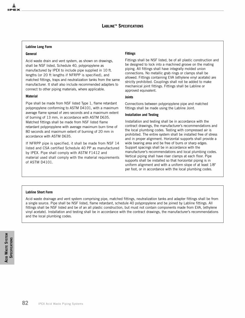
ACID
WAS
TESY
STEM
SPEC
IFIC
ATIO
NS
82 IPEX Acid Waste Piping Systems
LABLINETM SPECIFICATIONS
Labline Long Form
General
Acid waste drain and vent system, as shown on drawings,shall be NSF listed, Schedule 40, polypropylene asmanufactured by IPEX to include pipe supplied in 10 ft.lengths (or 20 ft lengths if NFRPP is specified), andmatched fittings, traps and neutralization tanks from the samemanufacturer. It shall also include recommended adapters toconnect to other piping materials, where applicable.
Material
Pipe shall be made from NSF listed Type 1, flame retardantpolypropylene conforming to ASTM D4101, with a maximum average flame spread of zero seconds and a maximum extentof burning of 13 mm, in accordance with ASTM D635.Matched fittings shall be made from NSF listed flameretardant polypropylene with average maximum burn time of80 seconds and maximum extent of burning of 20 mm inaccordance with ASTM D635.
If NFRPP pipe is specified, it shall be made from NSF 14listed and CSA certified Schedule 40 PP as manufacturedby IPEX. Pipe shall comply with ASTM F1412 andmaterial used shall comply with the material requirementsof ASTM D4101.
Fittings
Fittings shall be NSF listed, be of all plastic construction andbe designed to lock into a machined groove on the matingpiping. All fittings shall have integrally molded unionconnections. No metallic grab rings or clamps shall beallowed. Fittings containing EVA (ethylene vinyl acetate) arestrictly prohibited. Couplings shall not be added to makemechanical joint fittings. Fittings shall be Labline orapproved equivalent.
Joints
Connections between polypropylene pipe and matchedfittings shall be made using the Labline Joint.
Installation and Testing
Installation and testing shall be in accordance with thecontract drawings, the manufacturer’s recommendations andthe local plumbing codes. Testing with compressed air isprohibited. The entire system shall be installed free of stressand in proper alignment. Horizontal supports shall provide awide bearing area and be free of burrs or sharp edges.Support spacings shall be in accordance with themanufacturer’s recommendations and local plumbing codes.Vertical piping shall have riser clamps at each floor. Pipesupports shall be installed so that horizontal piping is inuniform alignment and with a uniform slope of at least 1/8"per foot, or in accordance with the local plumbing codes.
Labline Short Form
Acid waste drainage and vent system comprising pipe, matched fittings, neutralization tanks and adapter fittings shall be froma single source. Pipe shall be NSF listed, flame retardant, schedule 40 polypropylene and be joined by Labline fittings. Allfittings shall be NSF listed and be of an all plastic construction, but must not contain components made from EVA, (ethylenevinyl acetate). Installation and testing shall be in accordance with the contract drawings, the manufacturer’s recommendationsand the local plumbing codes.
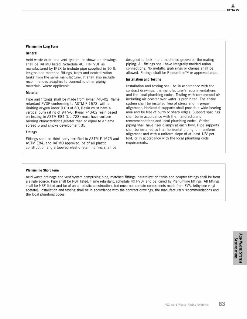
ACID
WASTE
SYSTEM
SPECIFICATION
S
83IPEX Acid Waste Piping Systems
Plenumline Long Form
General
Acid waste drain and vent system, as shown on drawings,shall be IAPMO listed, Schedule 40, FR-PVDF asmanufactured by IPEX to include pipe supplied in 10 ft.lengths and matched fittings, traps and neutralizationtanks from the same manufacturer. It shall also includerecommended adapters to connect to other pipingmaterials, where applicable.
Material
Pipe and fittings shall be made from Kynar 740-02, flameretardant PVDF conforming to ASTM F 1673, with alimiting oxygen index (LOI) of 60, Resin must have avertical burn rating of 94 V-0. Kynar 740-02 resin basedon testing to ASTM E84 (UL 723) must have surfaceburning characteristics greater than or equal to a flamespread 5 and smoke development 35.
Fittings
Fittings shall be third party certified to ASTM F 1673 andASTM E84, and IAPMO approved, be of all plasticconstruction and a tapered elastic retaining ring shall be
designed to lock into a machined groove on the matingpiping. All fittings shall have integrally molded unionconnections. No metallic grab rings or clamps shall beallowed. Fittings shall be Plenumline™ or approved equal.
Installation and Testing
Installation and testing shall be in accordance with thecontract drawings, the manufacturer's recommendationsand the local plumbing codes. Testing with compressed airincluding air booster over water is prohibited. The entiresystem shall be installed free of stress and in properalignment. Horizontal supports shall provide a wide bearingarea and be free of burrs or sharp edges. Support spacingsshall be in accordance with the manufacturer'srecommendations and local plumbing codes. Verticalpiping shall have riser clamps at each floor. Pipe supportsshall be installed so that horizontal piping is in uniformalignment and with a uniform slope of at least 1/8" perfoot, or in accordance with the local plumbing coderequirements.
Plenumline Short Form
Acid waste drainage and vent system comprising pipe, matched fittings, neutralization tanks and adapter fittings shall be froma single source. Pipe shall be NSF listed, flame retardant, schedule 40 PVDF and be joined by Plenumline fittings. All fittingsshall be NSF listed and be of an all plastic construction, but must not contain components made from EVA, (ethylene vinylacetate). Installation and testing shall be in accordance with the contract drawings, the manufacturer’s recommendations andthe local plumbing codes.
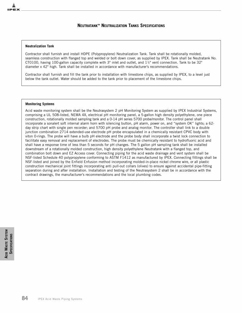
ACID
WAS
TESY
STEM
SPEC
IFIC
ATIO
NS
84 IPEX Acid Waste Piping Systems
NEUTRATANKTM NEUTRALIZATION TANKS SPECIFICATIONS
Neutralization Tank
Contractor shall furnish and install HDPE (Polypropylene) Neutralization Tank. Tank shall be rotationally molded,seamless construction with flanged top and welded or bolt down cover, as supplied by IPEX. Tank shall be Neutratank No.CT0100, having 100-gallon capacity complete with 3" inlet and outlet, and 11/2" vent connection. Tank to be 32"diameter x 42" high. Tank shall be installed in accordance with manufacturer’s recommendations.
Contractor shall furnish and fill the tank prior to installation with limestone chips, as supplied by IPEX, to a level justbelow the tank outlet. Water should be added to the tank prior to placement of the limestone chips.
Monitoring Systems
Acid waste monitoring system shall be the Neutrasystem 2 pH Monitoring System as supplied by IPEX Industrial Systems,comprising a UL 508-listed, NEMA 4X, electrical pH monitoring panel, a 5-gallon high density polyethylene, one piececonstruction, rotationally molded sampling tank and a 0-14 pH series 5700 probe/monitor. The control panel shallincorporate a sonalert soft internal alarm horn with silencing button, pH alarm, power on, and “system OK” lights; a 62-day strip chart with single pen recorder; and 5700 pH probe and analog monitor. The controller shall link to a doublejunction combination 2714 extended-use electrode pH probe encapsulated in a chemically resistant CPVC body withviton 0-rings. The probe will have a bulb pH electrode and the probe body shall incorporate a twist lock connection tofacilitate easy removal and replacement of electrodes. The probe must be chemically resistant to hydrofluoric acid andshall have a response time of less than 5 seconds for pH changes. The 5 gallon pH sampling tank shall be installeddownstream of a rotationally molded construction, high density polyethylene Neutratank with a flanged top, andcombination bolt down and EZ Access cover. Connecting piping for the acid waste drainage and vent system shall beNSF-listed Schedule 40 polypropylene conforming to ASTM F1412 as manufactured by IPEX. Connecting fittings shall beNSF-listed and joined by the Enfield Enfusion method incorporating molded-in-place nickel chrome wire, or all plasticconstruction mechanical joint fittings incorporating anti pull-out collars (olives) to ensure against accidental pipe-fittingseparation during and after installation. Installation and testing of the Neutrasystem 2 shall be in accordance with thecontract drawings, the manufacturer’s recommendations and the local plumbing codes.
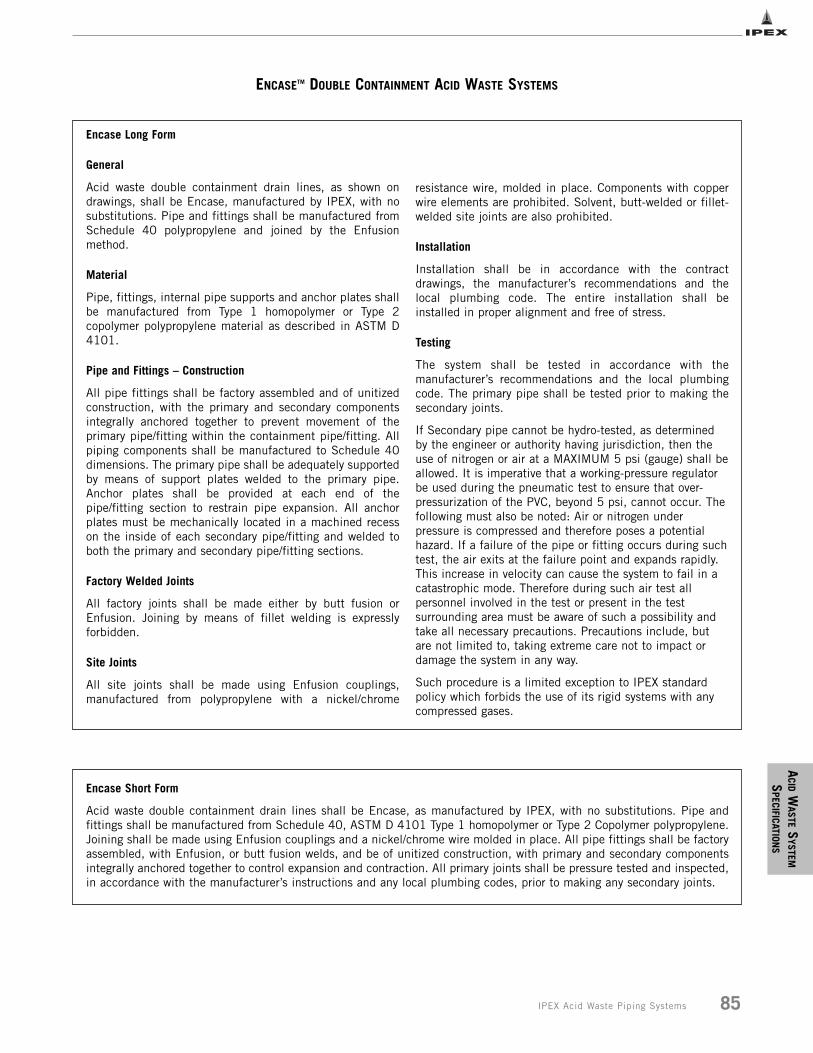
ACID
WASTE
SYSTEM
SPECIFICATION
S
85IPEX Acid Waste Piping Systems
ENCASETM DOUBLE CONTAINMENT ACID WASTE SYSTEMS
Encase Long Form
General
Acid waste double containment drain lines, as shown ondrawings, shall be Encase, manufactured by IPEX, with nosubstitutions. Pipe and fittings shall be manufactured fromSchedule 40 polypropylene and joined by the Enfusionmethod.
Material
Pipe, fittings, internal pipe supports and anchor plates shallbe manufactured from Type 1 homopolymer or Type 2copolymer polypropylene material as described in ASTM D4101.
Pipe and Fittings – Construction
All pipe fittings shall be factory assembled and of unitizedconstruction, with the primary and secondary componentsintegrally anchored together to prevent movement of theprimary pipe/fitting within the containment pipe/fitting. Allpiping components shall be manufactured to Schedule 40dimensions. The primary pipe shall be adequately supportedby means of support plates welded to the primary pipe.Anchor plates shall be provided at each end of thepipe/fitting section to restrain pipe expansion. All anchorplates must be mechanically located in a machined recesson the inside of each secondary pipe/fitting and welded toboth the primary and secondary pipe/fitting sections.
Factory Welded Joints
All factory joints shall be made either by butt fusion orEnfusion. Joining by means of fillet welding is expresslyforbidden.
Site Joints
All site joints shall be made using Enfusion couplings,manufactured from polypropylene with a nickel/chrome
resistance wire, molded in place. Components with copperwire elements are prohibited. Solvent, butt-welded or fillet-welded site joints are also prohibited.
Installation
Installation shall be in accordance with the contractdrawings, the manufacturer’s recommendations and thelocal plumbing code. The entire installation shall beinstalled in proper alignment and free of stress.
Testing
The system shall be tested in accordance with themanufacturer’s recommendations and the local plumbingcode. The primary pipe shall be tested prior to making thesecondary joints.
If Secondary pipe cannot be hydro-tested, as determinedby the engineer or authority having jurisdiction, then theuse of nitrogen or air at a MAXIMUM 5 psi (gauge) shall beallowed. It is imperative that a working-pressure regulatorbe used during the pneumatic test to ensure that over-pressurization of the PVC, beyond 5 psi, cannot occur. Thefollowing must also be noted: Air or nitrogen underpressure is compressed and therefore poses a potentialhazard. If a failure of the pipe or fitting occurs during suchtest, the air exits at the failure point and expands rapidly.This increase in velocity can cause the system to fail in acatastrophic mode. Therefore during such air test allpersonnel involved in the test or present in the testsurrounding area must be aware of such a possibility andtake all necessary precautions. Precautions include, butare not limited to, taking extreme care not to impact ordamage the system in any way.
Such procedure is a limited exception to IPEX standardpolicy which forbids the use of its rigid systems with anycompressed gases.
Encase Short Form
Acid waste double containment drain lines shall be Encase, as manufactured by IPEX, with no substitutions. Pipe andfittings shall be manufactured from Schedule 40, ASTM D 4101 Type 1 homopolymer or Type 2 Copolymer polypropylene.Joining shall be made using Enfusion couplings and a nickel/chrome wire molded in place. All pipe fittings shall be factoryassembled, with Enfusion, or butt fusion welds, and be of unitized construction, with primary and secondary componentsintegrally anchored together to control expansion and contraction. All primary joints shall be pressure tested and inspected,in accordance with the manufacturer’s instructions and any local plumbing codes, prior to making any secondary joints.
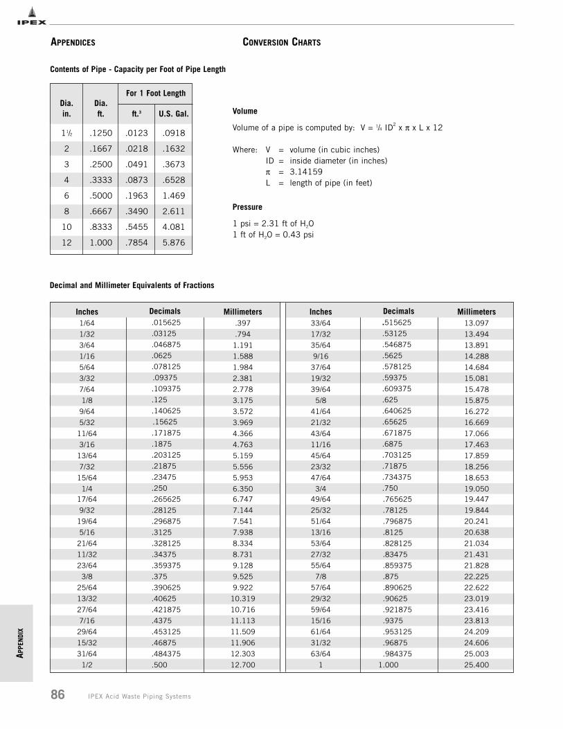
APPE
NDI
X
86 IPEX Acid Waste Piping Systems
APPENDICES
Contents of Pipe - Capacity per Foot of Pipe Length
Dia.in.
11/2
2
3
4
6
8
10
12
Dia.ft.
.1250
.1667
.2500
.3333
.5000
.6667
.8333
1.000
ft.3
.0123
.0218
.0491
.0873
.1963
.3490
.5455
.7854
U.S. Gal.
.0918
.1632
.3673
.6528
1.469
2.611
4.081
5.876
For 1 Foot Length
Volume
Volume of a pipe is computed by: V = 1/4 ID2 x π x L x 12
Where: V = volume (in cubic inches)ID = inside diameter (in inches)π = 3.14159L = length of pipe (in feet)
Pressure
1 psi = 2.31 ft of H2O1 ft of H2O = 0.43 psi
Decimal and Millimeter Equivalents of Fractions
Inches1/64
1/32
3/64
1/16
5/64
3/32
7/64
1/8
9/64
5/32
11/64
3/16
13/64
7/32
15/64
1/4
Decimals.015625
.03125
.046875
.0625
.078125
.09375
.109375
.125
.140625
.15625
.171875
.1875
.203125
.21875
.23475
.250
Millimeters.397
.794
1.191
1.588
1.984
2.381
2.778
3.175
3.572
3.969
4.366
4.763
5.159
5.556
5.953
6.350
Inches33/64
17/32
35/64
9/16
37/64
19/32
39/64
5/8
41/64
21/32
43/64
11/16
45/64
23/32
47/64
3/4
Decimals.515625
.53125
.546875
.5625
.578125
.59375
.609375
.625
.640625
.65625
.671875
.6875
.703125
.71875
.734375
.750
Millimeters13.097
13.494
13.891
14.288
14.684
15.081
15.478
15.875
16.272
16.669
17.066
17.463
17.859
18.256
18.653
19.05017/64
9/32
19/64
5/16
21/64
11/32
23/64
3/8
25/64
13/32
27/64
7/16
29/64
15/32
31/64
1/2
.265625
.28125
.296875
.3125
.328125
.34375
.359375
.375
.390625
.40625
.421875
.4375
.453125
.46875
.484375
.500
6.747
7.144
7.541
7.938
8.334
8.731
9.128
9.525
9.922
10.319
10.716
11.113
11.509
11.906
12.303
12.700
49/64
25/32
51/64
13/16
53/64
27/32
55/64
7/8
57/64
29/32
59/64
15/16
61/64
31/32
63/64
1
.765625
.78125
.796875
.8125
.828125
.83475
.859375
.875
.890625
.90625
.921875
.9375
.953125
.96875
.984375
1.000
19.447
19.844
20.241
20.638
21.034
21.431
21.828
22.225
22.622
23.019
23.416
23.813
24.209
24.606
25.003
25.400
CONVERSION CHARTS
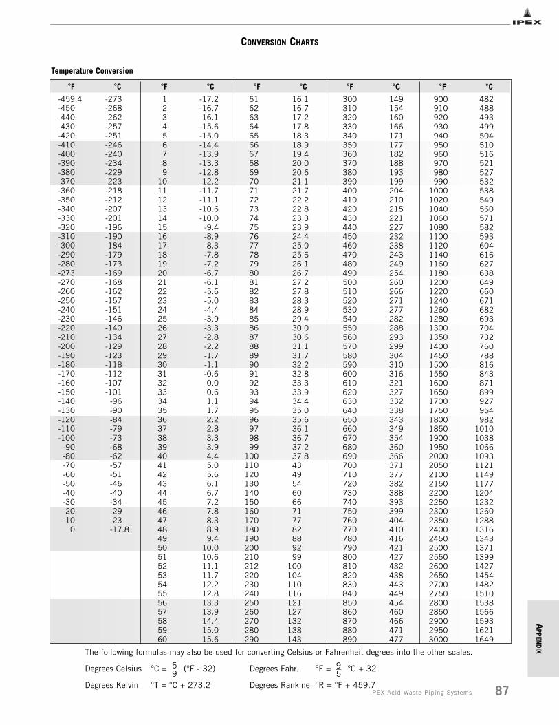
APPEN
DIX
87IPEX Acid Waste Piping Systems
CONVERSION CHARTS
°F
-459.4-450-440-430-420-410-400-390-380-370-360-350-340-330-320-310-300-290-280-273-270-260-250-240-230-220-210-200-190-180-170-160-150-140-130-120-110-100
-90-80-70-60-50-40-30-20-10
0
°C
-273-268-262-257-251-246-240-234-229-223-218-212-207-201-196-190-184-179-173-169-168-162-157-151-146-140-134-129-123-118-112-107-101
-96-90-84-79-73-68-62-57-51-46-40-34-29-23-17.8
°F
123456789
101112131415161718192021222324252627282930313233343536373839404142434445464748495051525354555657585960
°C
-17.2-16.7-16.1-15.6-15.0-14.4-13.9-13.3-12.8-12.2-11.7-11.1-10.6-10.0
-9.4-8.9-8.3-7.8-7.2-6.7-6.1-5.6-5.0-4.4-3.9-3.3-2.8-2.2-1.7-1.1-0.60.00.61.11.72.22.83.33.94.45.05.66.16.77.27.88.38.99.4
10.010.611.111.712.212.813.313.914.415.015.6
°F
616263646566676869707172737475767778798081828384858687888990919293949596979899
100110120130140150160170180190200210212220230240250260270280290
°C
16.116.717.217.818.318.919.420.020.621.121.722.222.823.323.924.425.025.626.126.727.227.828.328.929.430.030.631.131.732.232.833.333.934.435.035.636.136.737.237.84349546066717782889299
100104110116121127132138143
°F
300310320330340350360370380390400410420430440450460470480490500510520530540550560570580590600610620630640650660670680690700710720730740750760770780790800810820830840850860870880890
°C
149154160166171177182188193199204210215221227232238243249254260266271277282288293299304310316321327332338343349354360366371377382388393399404410416421427432438443449454460466471477
°F
900910920930940950960970980990
10001020104010601080110011201140116011801200122012401260128013001350140014501500155016001650170017501800185019001950200020502100215022002250230023502400245025002550260026502700275028002850290029503000
°C
482488493499504510516521527532538549560571582593604616627638649660671682693704732760788816843871899927954982
101010381066109311211149117712041232126012881316134313711399142714541482151015381566159316211649
The following formulas may also be used for converting Celsius or Fahrenheit degrees into the other scales.
Degrees Celsius °C = (°F - 32) Degrees Fahr. °F = °C + 32
Degrees Kelvin °T = °C + 273.2 Degrees Rankine °R = °F + 459.7
Temperature Conversion
59
95
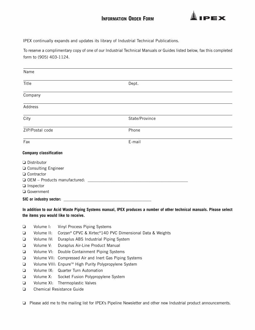
INFORMATION ORDER FORM
Company classification
❏ Distributor❏ Consulting Engineer❏ Contractor ❏ OEM – Products manufactured: ________________________________________________❏ Inspector❏ Government
SIC or industry sector: __________________________________________
In addition to our Acid Waste Piping Systems manual, IPEX produces a number of other technical manuals. Please selectthe items you would like to receive.
❏ Volume I: Vinyl Process Piping Systems
❏ Volume II: Corzan® CPVC & Xirtec®140 PVC Dimensional Data & Weights
❏ Volume IV: Duraplus ABS Industrial Piping System
❏ Volume V: Duraplus Air-Line Product Manual
❏ Volume VI: Double Containment Piping Systems
❏ Volume VII: Compressed Air and Inert Gas Piping Systems
❏ Volume VIII: EnpureTM High Purity Polypropylene System
❏ Volume IX: Quarter Turn Automation
❏ Volume X: Socket Fusion Polypropylene System
❏ Volume XI: Thermoplastic Valves
❏ Chemical Resistance Guide
❏ Please add me to the mailing list for IPEX's Pipeline Newsletter and other new Industrial product announcements.
IPEX continually expands and updates its library of Industrial Technical Publications.
To reserve a complimentary copy of one of our Industrial Technical Manuals or Guides listed below, fax this completed
form to (905) 403-1124.
Name
Title Dept.
Company
Address
City State/Province
ZIP/Postal code Phone
Fax E-mail

NOTES
______________________________________________________
______________________________________________________
______________________________________________________
______________________________________________________
______________________________________________________
______________________________________________________
______________________________________________________
______________________________________________________
______________________________________________________
______________________________________________________
______________________________________________________
______________________________________________________
______________________________________________________
______________________________________________________
______________________________________________________
______________________________________________________
______________________________________________________
______________________________________________________
______________________________________________________
______________________________________________________
______________________________________________________
______________________________________________________
______________________________________________________
______________________________________________________
______________________________________________________
______________________________________________________
______________________________________________________
______________________________________________________
______________________________________________________
______________________________________________________
______________________________________________________
______________________________________________________
______________________________________________________
______________________________________________________
SALES AND CUSTOMER SERVICE
Canadian Customers call IPEX Inc.
Toll free: (866) 473-9462
www.ipexinc.com
U.S. Customers call IPEX USA LLC
Toll free: (800) 463-9572
www.ipexamerica.com
About the IPEX Group of Companies
As leading suppliers of thermoplastic piping systems, the IPEX Group of
Companies provides our customers with some of the largest and most
comprehensive product lines. All IPEX products are backed by more than
50 years of experience. With state-of-the-art manufacturing facilities and
distribution centers across North America, we have established a reputation for
product innovation, quality, end-user focus and performance.
Markets served by IPEX group products are:
• Electrical systems
• Telecommunications and utility piping systems
• PVC, CPVC, PP, ABS, PEX, FR-PVDF and PE pipe and fittings (1/4" to 48")
• Industrial process piping systems
• Municipal pressure and gravity piping systems
• Plumbing and mechanical piping systems
• PE Electrofusion systems for gas and water
• Industrial, plumbing and electrical cements
• Irrigation systems
This literature is published in good faith and is believed to be reliable. Howeverit does not represent and/or warrant in any manner the information andsuggestions contained in this brochure. Data presented is the result oflaboratory tests and field experience.
A policy of ongoing product improvement is maintained. This may result inmodifications of features and/or specifications without notice.
MNINAWIP060502R © 2009 IPEX IND003UC
Products manufactured by IPEX Inc. and distributed in the United Statesby IPEX USA LLC.
ElastolivesTM, EncaseTM, Enfield®, FlowayTM, Labline®, Neutrasystem2TM,Neutratank® and PlenumlineTM are trademarks of IPEX Branding Inc.