Manual NanoTron - AFCO...
16
Manual NanoTron Conductivity Installation Maintenance Repair Manual Advantage Controls P.O. Box 1472 Muskogee, OK 74402 Phone: 800-743-7431 Fax: 888-686-6212 www.advantagecontrols.com email: [email protected] 7/2014
-
Upload
trinhquynh -
Category
Documents
-
view
215 -
download
0
Transcript of Manual NanoTron - AFCO...

1
Manual
NanoTronConductivity
InstallationMaintenanceRepairManual
Advantage ControlsP.O. Box 1472Muskogee, OK 74402Phone: 800-743-7431Fax: 888-686-6212www.advantagecontrols.comemail: [email protected]
7/2014

2
Table of Contents
Contents Page I. Introduction ................................................................................. 3
II. Description .................................................................................. 3 NanoTron-C & B2 Features ........................................................ 3
III. Installation Electrical Wiring .......................................................................... 4 Mounting Instructions ................................................................. 4 Logic and Relay Cards ............................................................... 5 IV. Front Panel Description .............................................................. 9 V. System Operation Overview ....................................................... 9 Description of Menus .................................................................. 9
Conductivity Sampling Methods ............................................... 10 A. Continuous B. Timed Samping C. Sample and Hold
Calibration Overview ................................................................ 10 A. Continuous B. Timed Samping C. Sample and Hold
VI. Maintenance ............................................................................. 11
VII. Troubleshooting ........................................................................ 11
VIII. NanoTron-C & B2 Menu Map ................................................... 12
IX. Warranty & 30 Day Billing Memo Policy ................................... 14
3
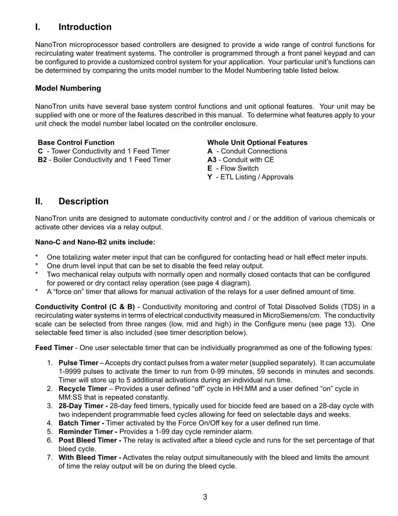
I. Introduction
NanoTron microprocessor based controllers are designed to provide a wide range of control functions for recirculating water treatment systems. The controller is programmed through a front panel keypad and can be configured to provide a customized control system for your application. Your particular unit’s functions can be determined by comparing the units model number to the Model Numbering table listed below.
Model Numbering
NanoTron units have several base system control functions and unit optional features. Your unit may be supplied with one or more of the features described in this manual. To determine what features apply to your unit check the model number label located on the controller enclosure.
Base Control Function C - Tower Conductivity and 1 Feed TimerB2 - Boiler Conductivity and 1 Feed Timer
Whole Unit Optional FeaturesA - Conduit ConnectionsA3 - Conduit with CEE - Flow SwitchY - ETL Listing / Approvals
II. Description
NanoTron units are designed to automate conductivity control and / or the addition of various chemicals or activate other devices via a relay output.
Nano-C and Nano-B2 units include:
* One totalizing water meter input that can be configured for contacting head or hall effect meter inputs.* One drum level input that can be set to disable the feed relay output.* Two mechanical relay outputs with normally open and normally closed contacts that can be configured for powered or dry contact relay operation (see page 4 diagram).* A “force on” timer that allows for manual activation of the relays for a user defined amount of time.
Conductivity Control (C & B) - Conductivity monitoring and control of Total Dissolved Solids (TDS) in a recirculating water systems in terms of electrical conductivity measured in MicroSiemens/cm. The conductivity scale can be selected from three ranges (low, mid and high) in the Configure menu (see page 13). One selectable feed timer is also included (see timer description below).
Feed Timer - One user selectable timer that can be individually programmed as one of the following types:
1. Pulse Timer – Accepts dry contact pulses from a water meter (supplied separately). It can accumulate 1-9999 pulses to activate the timer to run from 0-99 minutes, 59 seconds in minutes and seconds. Timer will store up to 5 additional activations during an individual run time.
2. Recycle Timer – Provides a user defined “off” cycle in HH:MM and a user defined “on” cycle in MM:SS that is repeated constantly.
3. 28-Day Timer - 28-day feed timers, typically used for biocide feed are based on a 28-day cycle with two independent programmable feed cycles allowing for feed on selectable days and weeks.
4. Batch Timer - Timer activated by the Force On/Off key for a user defined run time. 5. Reminder Timer - Provides a 1-99 day cycle reminder alarm. 6. Post Bleed Timer - The relay is activated after a bleed cycle and runs for the set percentage of that
bleed cycle. 7. With Bleed Timer - Activates the relay output simultaneously with the bleed and limits the amount
of time the relay output will be on during the bleed cycle.

4
III. Installation
Electrical WiringThe controller has an internal regulated power supply that will operate in the range of approximately 100 to 240 VAC on the incoming wiring. Output relay(s) are protected with a replaceable fuse. Relay output voltage will equal the incoming line voltage.
Prewired units are supplied with a 16 AWG cable with a 3-wire grounded USA 120 volt plug for incoming power and 18 AWG 3-wire grounded receptacle cords for all control relay outputs. Conduit units are supplied with liquid tights and adaptors for easy hard wiring to supplied connector.
NOTE: Liquid tight fittings and some labeled signal leads are provided for signal (low voltage) connections, such as water meter inputs.
WARNINGS1. The controller should be connected to its own isolated circuit breaker, and for best
results, the ground should be a true earth ground, not shared. Wiring must be done according to all applicable local codes.
2. Power (line voltage) must be disconnected while making any connections. If power is supplied to the unit, line voltage will be present on the relay cards.
3. Low voltage signal wires (probes, flow switch, water meter, etc.) should never be run in conduit with high voltage wires.
4. Hall effect meters that require +12 VDC must use an external power supply (TFS-PWR).
Mounting Instructions
Select a mounting location that provides the operator easy access to the unit and a clear view of the controls through the cover of the controller. The location should be convenient to grounded electrical connections, the needed sample line plumbing and is on a stable vertical surface.
WARNING: Avoid locations that expose the controller to direct sunlight, vapors, vibration, liquid spills or extreme temperatures; less than 0°F (-17.8°C) or greater than 120°F (50°C). EMI
(electromagnetic interference) from radio transmissions and electric motors can also cause damage or interference and should be avoided.
!
!

5
Logic and Relay Cards
+5 VDC
Ground
Conductivity
Temp
+ -Power
R B W GConductivity Probe
P S GMeter
+ -Flow
+ -Level
Signal
Note: Contacting head water metersjust use signal and ground. The +5 VDCis used with hall effect meters.
FUSE
FUSE
Ground
Relay 1
Power Supply
Relay 2
Neutral
Hot
Neutra
l
Ground
N/O N/C Neutra
l
Ground
N/O N/C
Relay 1 Out Relay 2 Out
Power In
Powered relayoutput jumperconfiguration
Dry contact relayoutput jumper configuration
Relay Card
NanoTron-C & B2 Logic Card
ContrastAdjust
Note: Use GND and N.O. for N.O. dry contact relay or use GND and N.C. for N.C. dry contact relay.
1 2 3
4 5
ON
OFF
Switch # Position Function1 OFF Backlight normally off; flashes on w/ alarm1 ON Backlight normally on; flashes off w/ alarm2 OFF Normal Operation2 ON “Burn-in” Mode3 OFF Normal Operation3 ON Clear Memory (Resets to factory defaults)4 OFF “A” Range Temp Comp - 5k thermistor4 ON “B” Range Temp Comp - 30k thermistor5 OFF Set for 1x6 LCD (Normal)5 ON Set for 4x20 LCD (Debug @ Factory)
Note: Relay 1 is for Conductivity Bleed. Relay 2 is for Single Timer

6
Electrode Installation
Controllers may come configured for various circulating water systems. Listed below are instructions for cooling tower and boiler typical installations. Your specific installation requirements may differ but should conform to these instructions as much as possible for proper operation.
A. Cooling Tower
The standard probe(s) and/or flow assembly for cooling tower installations is constructed of schedule 80 PVC and supplied with 3/4” slip fittings for installing into a sample line. To insure proper operation the sample line must have a flow rate of 3-10 gpm. Inlet pressure must be higher than outlet pressure in order for water to flow past the electrode(s) to achieve the required rate. The probes are temperature compensated for increased accuracy.
NOTES: 1. Install an isolation valve on either side of the flow assembly so electrodes can be
easily isolated for removal and cleaning. 2. A line strainer is recommended upstream from the probes to protect against fouling
and damage. 3. Systems with a flow switch require 2-3 gpm flow rate to operate outputs.
WARNINGS: 1. Electrodes are O-ring sealed, which if damaged will cause a leak.
2. Do not allow pH sensor tips to dry out, damage will occur. 3. Do not exceed a water temperature range of 32°F to 140°F. 4. Do not exceed a maximum pressure of 150 psi.
Typical Cooling Tower Installation Diagram
BLOWDOWN
SOLENOIDVALVE
FORCEON/OFFMENU
NanoTron
1 2
ENTER
CHILLERISOLATION VALVE
ISOLATION VALVE
COOLING TOWER
!

7
B. Boiler
Standard boiler electrodes have a MNPT stainless steel bushing and are supplied with a FNPT cross designed for mounting in the skimmer (surface) blowdown line. Sampling of the boiler’s water can be achieved using one of two typical plumbing configurations (continuous sampling or timed and/or hold sampling). For a successful installation, it is critical to observe the recommended distances and pipe sizes provided in the installation drawings.
For best results, the electrode cross should be mounted in a 1”skimmer blowdown line within 4’ of the boiler. Smaller line sizes and greater distances may affect the response time and accuracy of the electrode. A flow-throttling device down stream from the probe (within 24 inches) is required to ensure that the electrode is exposed to water and not steam. Properly installed and adjusted, this device will prevent flashing in the electrode chamber.
NOTES: 1. Install a fully ported type valve between the electrode and the boiler. This allows the
electrode to be isolated for removal and cleaning. 2. A flushing line and 1/4 turn type ball valve should be installed in the bottom of the
cross to periodically “flush” sediment from the electrode chamber. 3. Make sure the alignment arrows on the probe end up parallel to the flow for best
performance.
WARNINGS: 1. The probe must be fully immersed in the system water to read correctly.
Steam flashing will result in incorrect readings. 2. Do not exceed a maximum water temperature of 436°F (224°C) 3. Do not exceed a maximum pressure of 350 psi (24.1 bar) 4. A throttling device must be installed down stream from the elecrode.
Boiler Conductivity Electrodes
BE-32
Wiring Note: BE-32 probes require a 2 conductor cable from controller to probe.
!
8
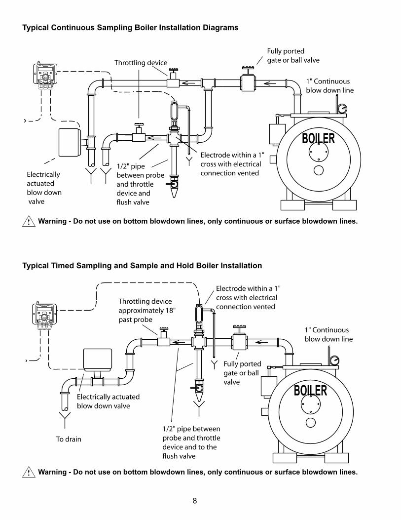
Typical Continuous Sampling Boiler Installation Diagrams
Throttling device
1/2" pipebetween probeand throttledevice and flush valve
Electricallyactuatedblow down valve
Electrode within a 1"cross with electricalconnection vented
Fully portedgate or ball valve
1" Continuousblow down line
FORCEON/OFFMENU
NanoTron
1 2
ENTER
! Warning - Do not use on bottom blowdown lines, only continuous or surface blowdown lines.
Typical Timed Sampling and Sample and Hold Boiler Installation
Throttling deviceapproximately 18"past probe
Electrode within a 1"cross with electricalconnection vented
1/2" pipe betweenprobe and throttledevice and to theflush valve
Electrically actuatedblow down valve
To drain
Fully portedgate or ball valve
1" Continuousblow down line
FORCEON/OFFMENU
NanoTron
1 2
ENTER
! Warning - Do not use on bottom blowdown lines, only continuous or surface blowdown lines.

9
IV. Front Panel Description
Timer1 Set Timer2 Set Configure Force SetWater Meters Clock Set
Set Time
Set Date
Day & Week
Pulse Recycle
On in 0001 Pulses
Run Time mm:ss
Off Time hh:mm
Run Time mm:ss
28-Day (Bio)
Every DayA:
All WeeksA:
Start 05:00aA:
Run Time hh:mmA:
Every DayB:
All WeeksB:
Start 05:00aB:
Run Time hh:mmB:
-options-No WeekWeek 1Week 2Week 3Week 4Odd WeeksEven WeeksAll Weeks
-Day Options-No Day; Sun; MonTue; Wed; Thu; Fri; M, W, FT, Th, SMon-FriSat & Sun AlternateEveryday
Flow SW: Open
Drum Lvls On
NanoTron
Firmware
Password 0000
Meter 1 Units
Meter1 Debounce
Meter 1 Value
Timer 2 Enabled Timeout1 mm:ss
Set Force On/Off key action here as:Ask, Both, Relay 1,Relay 2 or None.
Set Timeout valuesto desired Forced On time for each relay. If a timer is aBatch it will run forthe Batch timer’s run time when the Force On/Off is pressed.
Timers go back toauto mode afterForce On/Off timehas expired.
Enter to access, timer type shown, press Enter again to change type or to settings.
If water meter input Units is gallons or litersper pulse the accumulator isnumber of pulsesbefore activation.
If Units is pulsesper gallon/literaccumulator isnumber of gallonsor liters beforeactivation.
Reset Meter1?
Meter2 Enabled
FORCEON/OFFMENU
NanoTron
1 2
ENTER
Wed 10:59:57amMENU
FORCEON/OFF
ENTER
Press MENU to access menus or go backone layer in menu structure.Press FORCE to activate relays manuallyagain for Off and a third time back to auto.
Press ENTER to go a layer deeper in menu,to initiate a setting change and to set change.
Use up or down arrows to navigate throughmenu selections or setting options.
Use left or right arrows to move curser while making a numerical value change.
Main Menu Circle
Tmr1 Meter1
Tmr2 WM1+2
Disabledif 0000.
Notes: 1. If Menu is pressed while changing a valuethe value on screen will be the new value.
2. If Timer 2 is “After Timer 1” it will activate it’s Run each time Timer 1 completes a Run cycle.
3. Meter units and values must be set in the Water Meter menu for Pulse timers to work.
Select which meter(s)contacts activate timer.
Timer 2 has a fourth type selection;“After Timer 1” for sequential timers. See note 2 below.
Batch
Run Time mm:ss
Batch timers areactivated by theForce On/Offkey and will runfor the time sethere.
Force On: Ask
Timeout2 mm:ss
Increase value to prevent false contacts from water meter. Set debounce to 0 for paddle wheel meters.
V. System Operation Overview
Description of Menus
NanoTron controllers have three modes of operation, Run, Menu and Force. All menus are circular. Pressing the DOWN key will display the next line of information on the display.
Run - This mode is for normal operation. The control relays will only be automatically active in this mode. In the Run mode, the display will read system values. If an alarm is present, the display flashes with the alarm status.
The Run menu will display values such as day, time, date and other values depending upon the features present on the unit. The unit will automatically return to the Run mode if no keys are pressed for three minutes.
Menu - This mode is used to make adjustments to settings and readings on the controller. To access the Menu mode from the run screen, press the Menu key. Use the up or down arrow to scroll through the various menus. When you want to access a specific menu, press the Enter key. Once you have entered a sub-menu you will be able to step through that menu’s options with the up or down arrow key.
Force - Relays may be forced on or off for a user defined amount of time. Press the Force key to force relays on for the time configured in the Menu’s force sub-menu. Press it a second time to force them off for the same amount of time. Press a third time to go back to automatic Run mode. Unit returns to the Run mode automatically when the force time has elapsed.

10
Conductivity Sampling Methods
A. Continuous - Typical for most tower applications. The controller is constantly reading the sensor and activating the bleed relay based on readings relationship to the set point, set point direction and differential. Example: A rising set point of 1500 and differential of 50 the bleed relay would activate when the conductivity rises above 1500 and stays on until the reading drops to 1450.
B. Timed Sampling - A sample timer allows the conductivity to be sampled at periodic intervals. Sample intervals are adjustable from 1 minute to 99 hours, 59 min. Sample duration (on-time) is
adjustable from 1 second to 99 minutes, 59 seconds. If the reading is below the set point by the differential amount the bleed relay will be turned off at the end of the sample duration and the sample interval countdown reinitiated. If the reading is above the set point at the end of the sample method the bleed relay stays on until the reading drops by the differential amount.
C. Sample and Hold - Also uses a sample timer for periodic sampling intervals. The unit will sample for its duration then hold the blowdown valve closed for a settable period (hold time). The conductivity is checked at the end of the hold period, if additional blowdown is required the blowdown valve is held open for a preset amount of time (blowdown time). Then sample cycle is repeated until the reading is below the set point at the end of a hold cycle and the sample interval countdown reinitiated.
Note: Timed Sampling and Sample and Hold are typically used for boiler applications but Timed sampling can also be used on small towers. On these tower applications the probe is installed in the bleed line before the bleed valve.
Calibration Overview
The NanoTron controllers update the conductivity reading every two seconds with a running average. Nanotron controller’s conductivity scale should be selected so that the conductivity setpoint is as close as possible to the middle of the scale. (See page 13 menu for setting scale).
Note: If a controller is using Timed Sampling or Sampling and Hold methods of control the conductivity reading shown in the RUN mode may not be a current reading. The controller will hold and display the conductivity value seen at the end of the last sample or hold duration. To see a current reading force on the bleed relay with either the Force button or via the Calibration menu.
A. Continuous - Calibrating continuous sampling units can be done at any time with the probe in a steady stream of water with no air or steam present.
B. Timed Sampling - While in the calibration menu there is a selection to force on the bleed relay. It will force it into the sample period. After 1-2 minutes verify that the reading is stable then enter the desired calibration value.
C. Sample and Hold - While in the calibration menu there is a selection to force on the bleed relay. It will force the unit into its sample and hold periods and calibration should be done during the hold after a fresh sample.
Notes: 1. If steam is flashing on boiler probes a stable reading will not be maintained and the controller will
not track. 2. If you change the conductivity scale in the Configure menu you MUST then go to Diagnostics
and Reset the Cal then go to the Calibration menu and calibrate accordingly.

11
VI. MaintenanceThe only required maintenance for normal uninterrupted operation of your controller is cleaning of the electrode(s). After initial start up, it is a good idea to clean the electrode frequently until a schedule based on need has been developed. Since each application is unique, it is difficult to estimate the required frequency of cleaning. The first cleaning should take place after about one week of the system being on line.
To determine the required cleaning frequency, record the reading on the controller before the electrode is removed for cleaning. After cleaning, record the new reading. If a change is observed in the two readings, the electrode was dirty. The more significant the change, the dirtier the electrode. If no change occurs, cleaning needs to be done less often.
Conductivity Electrode Cleaning Procedure
1. Record the current conductivity reading.2. Turn off water flow through the electrode loop, bleed pressure from the line and remove
electrode.3. Use a clean cloth and a mild cleaning solution to remove loose dirt etc., from the flat
surface of the electrode.4. If the electrode has deposits such as scale attached to the electrode surface a more
aggressive cleaning approach will be needed. There are several ways to do this, the preferred method being the one that is easiest for the user.
a. Use a mild acid solution to dissolve deposits. b. Lay a piece of sandpaper (200 grit or finer) on a flat surface such as a bench
top. “Sand” electrode to remove stubborn deposits. (Do not wipe surface with your finger.) Oil from your skin will foul carbon tips.
5. Reinstall the electrode in the system. After the reading stabilizes, calibrate the unit to a reliable test reading.
Many times an electrode can appear to be clean, but the unit still cannot be calibrated. If this is the case, use one of the more aggressive electrode cleaning procedures listed in step 4 above. Recheck the calibration after completion of this procedure. If no change was observed in the reading, replace the electrode. If a change occurred but the unit still will not calibrate, repeat procedure as many times as necessary.
VII. TroubleshootingThe Advantage NanoTron controller is designed for many years of trouble free operation. Should a problem occur, refer to the following chart to help identify the problem. If replacement is required, follow the procedures listed in the Warranty and Factory Service portion of this manual.
SYMPTOM POSSIBLE CAUSE SOLUTIONFalse reading .................................... Bad or dirty electrode Clean, as needed Out of calibration Calibrate unitWill not calibrate ............................... Dirty electrode Clean electrode Faulty electrode Replace electrode if needed Faulty wiring to electrode Replace wiring if needed No system power .............................. Check power source Plug into different receptacle Check fuse Replace as needed Check connections Make sure ribbon cables are securePulse timer not activating ................. Check wiring Repair as needed Check external device Repair/replace as neededOutputs not energized ...................... No flow Check sample line for clogged pipes or strainers Check fuse Replace as needed

12
Calibration Bleed Set Timer Set Water Meter Clock Set Force Set Diagnostics
Cal Temp 077°F Continuous Setpoint 01500 Pulse Run After 0010 Password 0000 Reset Meter? N Set Time Force On: Ask Force On: Both Nano-C
Cal 02500µS Diff 0100 Run Time mm:ss Flow Sw: Close Meter Units Set Date Force On: Tmr FW: ?.?.?
Direction: Rise Post Bleed 010% of Bld Drum Lvl: Off Meter Value Set Day & Week Force On: Bld Test Keypad
High Alarm 2500 Limit Time hh:mm Probe Type Tower (140°F) Meter Debounce Force On: None Test Display
Low Alarm 00600 With Bleed Limit Time hh:mm Boiler (430°F) Bleed mm:ss Reset Cal? N
Limit hh:mm Timer Off Imperial Units Metric Units Timer mm:ss Checked Cal? N
Sample&Hold Interval hh:mm
Batch Run Tim mm:ss
Cond Scale Low (10-1000)
Duration mm:ss
Reminder Reset Timer? N
MID (100-7000)
Bleed mm:ss
Reminder In: dd
HIGH (1K-20K)
Hold mm:ss
28-Day (Bio) A: All Days
Cond Units µS/cm
Setpoint 01500
A: All Weeks
ppm/TDS
Direction: Rise
A: Start 12:00a
Zero Cond? N
High Alarm 02500
A: Run Time hh:mm
Feed OK W/Bld No Feed W/Bld
Low Alm 00600
A: Prbld hh:mm
Check Cal: dd
Timed Mode Interval hh:mm
A: Lkout hh:mm
No Feed No Flow Feed OK NoFlow
Duration mm:ss
B: All Days
Setpoint 01500
B: All Weeks
Diff 0100
B: Start 12:00a
Direction: Rise
B: Run Time hh:mm
High Alm 02500
B: Prbld hh:mm
Low Alm 00600
B: Lkout hh:mm
Recycle Off Time hh:mm
Run Time mm:ss
Raw A/D: ????
Cal Factor 0100
Zero Adj: 0000
Utility
Always Count
Increase value to prevent false contacts from water meter. Set debounce to 0 for paddle wheel meters. Reducevalue if contacts aremissed.
Boiler’s high scaleis 1K-10K
Force Bleed? N
If set for Timed or Sample & Hold, force on bleed to get fresh sample.
If Sample & Hold, it will cycle through tothe sample. Thenhold & calibrationshould be done at this time.
WM: C or O
The factory default for towers is approx 500 and boilers is 3500.
0-32,767 scale
Identify logicstate of vaiousdigital inputs.

13
Calibration Bleed Set Timer Set Water Meter Clock Set Force Set Diagnostics
Cal Temp 077°F Continuous Setpoint 01500 Pulse Run After 0010 Password 0000 Reset Meter? N Set Time Force On: Ask Force On: Both Nano-C
Cal 02500µS Diff 0100 Run Time mm:ss Flow Sw: Close Meter Units Set Date Force On: Tmr FW: ?.?.?
Direction: Rise Post Bleed 010% of Bld Drum Lvl: Off Meter Value Set Day & Week Force On: Bld Test Keypad
High Alarm 2500 Limit Time hh:mm Probe Type Tower (140°F) Meter Debounce Force On: None Test Display
Low Alarm 00600 With Bleed Limit Time hh:mm Boiler (430°F) Bleed mm:ss Reset Cal? N
Limit hh:mm Timer Off Imperial Units Metric Units Timer mm:ss Checked Cal? N
Sample&Hold Interval hh:mm
Batch Run Tim mm:ss
Cond Scale Low (10-1000)
Duration mm:ss
Reminder Reset Timer? N
MID (100-7000)
Bleed mm:ss
Reminder In: dd
HIGH (1K-20K)
Hold mm:ss
28-Day (Bio) A: All Days
Cond Units µS/cm
Setpoint 01500
A: All Weeks
ppm/TDS
Direction: Rise
A: Start 12:00a
Zero Cond? N
High Alarm 02500
A: Run Time hh:mm
Feed OK W/Bld No Feed W/Bld
Low Alm 00600
A: Prbld hh:mm
Check Cal: dd
Timed Mode Interval hh:mm
A: Lkout hh:mm
No Feed No Flow Feed OK NoFlow
Duration mm:ss
B: All Days
Setpoint 01500
B: All Weeks
Diff 0100
B: Start 12:00a
Direction: Rise
B: Run Time hh:mm
High Alm 02500
B: Prbld hh:mm
Low Alm 00600
B: Lkout hh:mm
Recycle Off Time hh:mm
Run Time mm:ss
Raw A/D: ????
Cal Factor 0100
Zero Adj: 0000
Utility
Always Count
Increase value to prevent false contacts from water meter. Set debounce to 0 for paddle wheel meters. Reducevalue if contacts aremissed.
Boiler’s high scaleis 1K-10K
Force Bleed? N
If set for Timed or Sample & Hold, force on bleed to get fresh sample.
If Sample & Hold, it will cycle through tothe sample. Thenhold & calibrationshould be done at this time.
WM: C or O
The factory default for towers is approx 500 and boilers is 3500.
0-32,767 scale
Identify logicstate of vaiousdigital inputs.
VIII. NanoTron-C & B2 Menu Map
NanoTron conductivity units have a main menu circle that includes:
Calibration - Calibrating the conductivity readingBleed Set - Setting the conductivity bleed set point, sample
method and alarmsTimer Set - Select the timer type and run valuesConfigure - Password, flow switch direction, probe type,
units of measure and moreWater Meter - Reset totalizer and setting contact valueClock Set - Set time, date and weekForce Set - Set the force on time for manual relay
activationsDiagnostics - Tests and calibration reset
14
IX. Manufacturer’s Product Warranty Advantage Controls warrants units of its manufacture to be free of defects in material or workmanship. Liability under this policy extends for 24 months from date of installation. Liability is limited to repair or replacement of any failed equipment or part proven defective in material or workmanship upon manufacturer’s examination. Removal and installation costs are not included under this warranty. Manufacturer’s liability shall never exceed the selling price of equipment or part in question. Advantage disclaims all liability for damage caused by its products by improper installation, maintenance, use or attempts to operate products beyond their intended functionality, intentionally or otherwise, or any unauthorized repair. Advantage is not responsible for damages, injuries or expense incurred through the use of its products. The above warranty is in lieu of other warranties, either expressed or implied. No agent of ours is authorized to provide any warranty other than the above.
30 Day Billing Memo Policy Advantage Controls maintains a unique factory exchange program to ensure uninterrupted service with minimum downtime. If your unit malfunctions, call 1-800-743-7431, and provide our technician with Model and Serial Number information. If we are unable to diagnose and solve your problem over the phone, a fully warranted replacement unit will be shipped, usually within 48 hours, on a 30 Day Billing Memo. This service requires a purchase order and the replacement unit is billed to your regular account for payment. The replacement unit will be billed at current list price for that model less any applicable resale discount. Upon return of your old unit, credit will be issued to your account if the unit is in warranty. If the unit is out of warranty or the damage not covered, a partial credit will be applied based upon a prorated replacement price schedule dependent on the age of the unit. Any exchange covers only the controller or pump. Electrodes, liquid end components and other external accessories are not included.
FCC Warning
This equipment generates and uses radio frequency energy and if not installed and used properly, that is, in strict accordance with the manufacturer’s instruction, may cause interference to radio communications. It has been type tested and found to comply with the limits for a class A computing device pursuant to subpart J of part 15 of FCC Rules, which are designed to provide reasonable protection against such interference when operated in a commercial or industrial environment. Operation of this equipment in a residential area is likely to cause interference in which case the user, at his own expense, will be required to take whatever measures necessary to correct the interference.

15

16
Get the Advantage in Water Treatment EquipmentAdvantage Controls can give you the Advantage in products, knowledge and support on all of your water treatment equipment needs.
Cooling Tower Controllers
Boiler Blow Down Controllers
Blow Down Valve Packages
Solenoid Valves
Water Meters
Chemical Metering Pumps
Corrosion Coupon Racks
Chemical Solution Tanks
Solid Feed Systems
Feed Timers
Filter Equipment
Glycol Feed Systems
Pre Fabricated Systems
Get the Advantage
5
4
3
2
1
ENTER
HELP
5
4
3
CHANGE
RUN
SET UP0
9
8
2
1
7
6
HOME
BACK