Manual - ldt-infocenter · Calculation of Resistors ... (LPT) for the utilization of the print...
120
All logos, manufacturer- and product names are trademarks of the respective manufacturer. Light-Control by Computer Manual Version 2 All rights reserved Copyright: Railware Andrea Hinz Dieffler Straße 18a D-66701 Beckingen Phone: 0049 68 32 / 80 73 94 Fax: 0049 68 32 / 80 73 95 Web: www.Light-at-Night.com E-Mail: [email protected]
Transcript of Manual - ldt-infocenter · Calculation of Resistors ... (LPT) for the utilization of the print...

All logos, manufacturer- and product names are trademarks of the respective manufacturer.
Light-Control by Computer
Manual
Version 2
All rights reserved
Copyright:
Railware Andrea Hinz
Dieffler Straße 18a D-66701 Beckingen
Phone: 0049 68 32 / 80 73 94 Fax: 0049 68 32 / 80 73 95
Web: www.Light-at-Night.com E-Mail: [email protected]

Light@Night Copyright Andrea Hinz
Page 2 reprint or copy prohibited

Copyright Andrea Hinz Light@Night
reprint or copy prohibited Page 3
Table of Contents
Table of Contents ..................................................................................... 3 Congratulation! ......................................................................................... 5 New features within version 2 ................................................................... 7 System Requirement ................................................................................ 9 Hardware Installation .............................................................................. 11 Software Installation from CD-ROM ........................................................ 15 Installation of a further Light-Display Module........................................... 17 The Power- Module ................................................................................ 19 Options................................................................................................... 23
Switch-Groups.................................................................................... 23 Daytimes ............................................................................................ 24 Lamp Adjustments.............................................................................. 25 Interface Hardware ............................................................................. 26
System- and Lamp Tests ........................................................................ 29 About electric, wiring and current consumption........................................ 31
Transformers...................................................................................... 31 Wiring-up............................................................................................ 32 Light-Display....................................................................................... 34 Incandescent Lamps........................................................................... 36 Light Emitting Diodes (LED)................................................................ 37 Current, Voltage and Resistance ........................................................ 39 Calculation of Resistors ...................................................................... 40 Several Consumers at one output....................................................... 42
Function and Mode of Operation............................................................. 45 Address.............................................................................................. 45 Text.................................................................................................... 45 Frame................................................................................................. 46 The Clock........................................................................................... 46 Twilight Times .................................................................................... 47 Switch-Groups.................................................................................... 47
The Light-Spots ...................................................................................... 49 Connecting LEDs and Incandescent Lamps............................................ 53
Single Light-Spots .............................................................................. 53 Light Chain......................................................................................... 54 Building Site ....................................................................................... 55 Traffic Light simple and pedestrians.................................................... 56 Traffic Light crossroad / intersection................................................... 58 Signal Post ......................................................................................... 60 Television Set..................................................................................... 62

Light@Night Copyright Andrea Hinz
Page 4 reprint or copy prohibited
Rail Crossing.......................................................................................63 Gas Street Lamp .................................................................................64 Firework Effects...................................................................................64
Realistic Illumination at the Model-Railway Layout ...................................67 House Illuminations .............................................................................67
Which type of light is suitable for house illumination?.......................69 Typical Switch-Groups.....................................................................71
At the Road .........................................................................................71 Type of Lights for Street Illumination................................................75 Type of Lights at the Road Side and at the Car Traffic .....................75 Type of Light for other purposes......................................................76 Typical Switch-Groups.....................................................................76
Day of an open door at our industrial area: ..........................................77 Type of Lights for Industrial Purposes..............................................78 Typical Switch-Groups.....................................................................79
At the Railway Station .........................................................................80 Type of Light at the Railway Station.................................................81 Typical Switch-Groups.....................................................................81
At the Railroad Embankment ...............................................................82 Type of Lights at the Railroad Embankment.....................................84 Typical Switch-Groups.....................................................................84
Building Site ........................................................................................85 Type of Light for Building Sites ........................................................86 Typical Switch-Groups.....................................................................87
Remote Control with HSI-88 ....................................................................89 Premises Illumination...............................................................................93
Practical Notes ..................................................................................100 Weather Simulation ...............................................................................103 The `Finder`...........................................................................................107 Interface for other Software (API)...........................................................109 Operating with Railware.........................................................................111 Future Extensions..................................................................................113 Figure Directory.....................................................................................115 Index .....................................................................................................117

All logos, manufacturer- and product-names are trademarks of the respective manufacturer.
Congratulation!
You have decided to purchase a modern unique system for generating various light effects on your model-railway layout. The PC will not only control the ON- and OFF-periods of the illuminations but also the different light effects. This will give you the advantage of low pricing as well as the possibility of various expansions of the system. The company Railware (www.Railware.com) is the manufacturer of the Light@Night Software. For running the Light@Night software it is imperative to use a Light-Display and a Light-Interface manufactured and supplied by Littfinski DatenTechnik (www.LDT-Infocenter.com). All modules and extensions are available directly by the named manufacturers. We are wishing you having a good time with your new light control!

Light@Night Copyright Andrea Hinz
Page 6 reprint or copy prohibited

Copyright Andrea Hinz Light@Night
reprint or copy prohibited Page 7
New features within version 2
During the first years on the market Light@Night has found a considerable amount of prospective buyers. Out of this reason we decided not to publish an extension (comfort version) as initially intended but meet at first the requests received several times from the users. The important issues:
l In future there will be only one software version which includes all available functions
l Remote control of light spots and switch-groups by keys by means of HSI-88 and s88 feedback modules
l Premise illumination with realistic day- and night transition l Weather simulation including clouds, rain and thunder l Support of the power- module l Up to 7 light modules in arbitrary sequence l Firework effects l 3D- sound for rain, thunder and firework l Searching of light spots
Light@Night runs still under Windows 95, 98 and Me. Please take into account that you need a PC with DirectX and sufficient capacity when using especially the 3D sound.

Light@Night Copyright Andrea Hinz
Page 8 reprint or copy prohibited

Copyright Andrea Hinz Light@Night
reprint or copy prohibited Page 9
System Requirement
Light@Night runs on almost any PC with a Windows operating system of Windows 95 or higher. We recommend particularly modern operating systems such as e.g. Windows 2000, XP or upgrades.
Operating system Windows 95, 98, Me, NT, 2000, XP or higher CPU Intel or AMD from 300Mhz clock frequency Working memory 128 Mbyte RAM Interface Light@Night Printer connection port LPT (*)
If you want to run the Light@Night software together with model-railway control software on your PC you have to attend to some stringent requirements, because the control software as well as Light@Night need some system resources. In this case please find out the system requirements of your model railway control software and attend to the specific instruction for an optimal operation. In a doubtful case you should consider to use a second, probably older PC exclusive for Light@Night. In case of a common operation of Railware and a model-railway control software the following PC-system requirements are necessary:
Operating system Windows 2000, XP or higher CPU Intel or AMD from 1200Mhz clock frequency Working memory 1024 Mbyte RAM Interface Light@Night Printer connection port LPT (*)
(*) The connection via an USB- Adapter is technically not possible.
On some few Laptop computers it can be possible that the parallel interface will not comply with the actual standards. In this case Light@Night cannot be used on this Laptop.
It is possible to install a further parallel interface port (LPT) for the utilization of the print functions (the list of light-spots).

Light@Night Copyright Andrea Hinz
Page 10 reprint or copy prohibited

Copyright Andrea Hinz Light@Night
reprint or copy prohibited Page 11
Hardware Installation
The light-display modules have to be connected to the parallel-interface port (LPT) of a PC via an interface-module (Light-Interface). All programs have to be closed and the PC switched off before you connect the light interface module!
• Connect the interface-module to the first light-display module. Attend to equal position of the pin-bar to the socket bar.
• Screw on the modules onto a wooden plate or to the layout frame by using the attached set of screws.
• Connect the enclosed cable to the interface-module and to the printer interface port of the PC.
• Connect a customary model railway transformer (1) to the AC clamps of the light-display module.
• Connect up to 40 individual consumers onto each light-display module.
Connect or disconnect light display modules only during switched-off time of the system! Otherwise the modules
can be destroyed!
The PC has to be switched off before connecting or disconnecting the connection cable! Danger, the system
can be destroyed!
(1) By using small electric bulbs (e.g. Viessmann) for the illumination of streets it is recommended to use a customary 12V transformer for low-voltage illumination (halogen lamps), because a 16 Volt model railway transformer will reduce the lifetime of the bulbs considerable.

Light@Night Copyright Andrea Hinz
Page 12 reprint or copy prohibited
Figure 1: Light-Display with Light-Interface from LDT
The above picture shows a Light-Interface and a Light-Display with 40 outputs. The Light-Interface shall be connected to the printer interface port (LPT) of the computer by use of the enclosed cable (25poles pin-pin). The maximum length of the cable should not exceed 3 meters. The Light-Interface takes over the conversion of the signals from the PC and assures the prescribed galvanic separation between PC and model railway layout. Up to 7 Light-Displays can be connected to each Light-Interface. The modules can be connected directly via the existent pin plugs. The modules have to be carefully screwed onto the base plate to prevent damages while press or depress the snap-in connections. The incandescent lamps and light emitting diodes have to be connected onto the outputs 1 to 40. These connections will switch against ground and can cover a load of 500mA each. For the voltage supply of the lamps and LEDs there are three outputs available at clamp 7. Each output is protected by a multifuse and can cover a load of max. 1 Ampere. Customary transformers suitable for halogen lamps with 12 Volt AC and about 50VA shall make the supply for modules, incandescent lamps and LEDs. By exclusive use of light emitting diodes is

Copyright Andrea Hinz Light@Night
reprint or copy prohibited Page 13
it possible to use model railway transformers (e.g. Titan) with 16Volt AC. Each module should get the supply from a separate transformer.
During booting a PC some main-boards can induce a flickering of the connected lamps. To prevent this please switch-on the supply transformers not before the PC is
ready to operate.

Light@Night Copyright Andrea Hinz
Page 14 reprint or copy prohibited

Copyright Andrea Hinz Light@Night
reprint or copy prohibited Page 15
Software Installation from CD-ROM
Together with this manual you received a CD-ROM. The CD-Rom contains the software for the operation of the light-display modules. For the installation of the software is a license-key required. You can find the license-key on the backside of this manual.
• Please insert the CD-ROM into the CD-ROM disk drive.
• The installation program will start automatically. In case the function “Auto start“ has been set to “Off“ on your PC please start the program with “Execute…“ at the Windows start menu and enter the following line (without ` sign) : ‘d:\setup.exe’. Please replace the letter `d` with the letter-code of your CD-ROM drive.
• Now appears a menu for choosing the language for installation.
• Follow now the instruction of the installation program.
• Enter the directory where Light@Night shall be installed. Suggestion ‘C:\Program\LightAtNight’.
• The following installation will run automatically.
• Enter now your license-key. You will find the key on the backside of this manual.
• It is possible that a re-start of the PC will be required.
Light@Night is now ready to operate. For your first trials you can find a module including all sample setups on the screen after you started the program.

Light@Night Copyright Andrea Hinz
Page 16 reprint or copy prohibited

Copyright Andrea Hinz Light@Night
reprint or copy prohibited Page 17
Installation of a further Light-Display Module
Connect or disconnect Light-Display-modules (LDT Light- or Power-Display) only during switched-off time of the PC! All transformers of connected light-display modules have
to be switched off. Danger of destruction!
The extension with further light-display modules is very simple. It is possible to connect up to seven LDT Light-Display modules directly behind each other. Each module contains a socket for the connection of the next module. Connect extension modules onto the last existing module.
Figure 2: Pin bar connection
• At first switch off all light-display module transformers.
• Connect the new module to the pin bar of the last already attached module and fasten the module with screws onto a solid base plate.
• Connect a suitable transformer.
• The new LEDs and incandescent lamps can now be connected.
• Switch-on all transformers and activate the PC.
• The new module receives the next afferent module number (module numbers of 1 to 7 are possible).

Light@Night Copyright Andrea Hinz
Page 18 reprint or copy prohibited
• The module has to be announced with type at the dialog `Light Module` under `Options` and `Module`.
Setting the light module type vacant vacant vacant vacant Interrupt
Figure 3: Type of Light Module
The transformers of all light modules have to be switched-off before connecting or disconnecting a light-display module. Danger of destruction!
Before connecting or disconnecting the connection cables or modules the pc has to be switched off!
Danger of destruction!

Copyright Andrea Hinz Light@Night
reprint or copy prohibited Page 19
The Power- Module
The new power- module contains 24 outputs which can be loaded with up to 2,5 Ampere each. Therefore it will be especially suitable for replacing existing relay-controlled model railway illumination and for the simultaneous control of many street illumination lamps and as well for 12 Volt Halogen lamps with up to 20 Watt. It will be possible to mix it with the Light-Display-Modules in an arbitrary sequence. The module occupation and sequence has to be set within the software under `Options` and `Light Modules`. Up to 7 modules can be used in combination to your requirement.
Figure 4: The LDT Light-Power-Module
The Light-Power-Module has to be supplied with direct current. Therefore is it required to use a direct-current power supply unit with 12 or 15 Volt dc output and sufficient capacity. The switched mode mains power supplies from e.g. manufacturer Reichelt or Conrad are especially recommended.

Light@Night Copyright Andrea Hinz
Page 20 reprint or copy prohibited
Figure 5: 40 Watt switched mode mains power supply (Reichelt)
Figure 6: 150 Watt switched mode mains power supply (Reichelt)
Switched mode mains power supplies contain an electronic overload safety device for the protection of the power supply and the connected consumers. If the protection device has been triggered the power supply unit has just to be switched off for a short time. If the Light-Power-Modules will be supplied by switched mode mains power supplies the first module at the Light-Interface should be normal Light-Display-Module because the Interface receives the power supply from the first module. If the first module would be a Light-Power-Module with a switched mode mains power supply it could be possible that during a network overload the complete light control will be switched off.

Copyright Andrea Hinz Light@Night
reprint or copy prohibited Page 21
Figure 7: Correct Module Sequence
Figure 8: Incorrect Module Sequence
Figure 9: Correct Module Sequence

Light@Night Copyright Andrea Hinz
Page 22 reprint or copy prohibited
With reason to a temporary enlarged current consumption of cold incandescent lamps and by frequent switching intervals is it required to use an over dimensioned switched mode mains power supply. For example is a 100 Watt power supply required for a thunder lightning with three 20 Watt Halogen lamps despite only one lamp out of three will be switched-on at the time. 24 outputs with 2.5 Ampere each will add up to 60-Ampere total current. This will be 720 Watt by 12 Volt. If this theoretical load will be really required is a direct current power supply of this capacity required. Especially for this high current flow is it very important to attend to the wire diameters between power supply and Light-Power-Module. Also the diameters of cables between the outputs and the distribution to the current consumers should be suitable to the expected current flow. The following tables will give some suitable recommendation:
Power supply - Light-Power-Module Length Wire cross section
Up to 2 meter 1,5 sq mm Up to 5 meter 2,5 sq mm
Light-Power-Module – Consumer Length Wire cross section
Up to 3 meter 0,75 sq mm Up to 6 meter 1,5 sq mm

Copyright Andrea Hinz Light@Night
reprint or copy prohibited Page 23
Options
There are numerous important settings available at the main menu under “Options“. Those settings will be described within the following sections.
Switch-Groups Under the expression “Switch-Group” Light@Night understands the possibility to switch one or several light-spots on or off at particular times. At first the required switch-group will be defined and assigned with switch times. For the setting-up of a new switch-group a new empty entry-line has to be created at the list with the “+” key. The names of the switch-groups can be selected to your requirement. It is recommended to use meaningful names such as e.g. “Station Forecourt”, “Streets” or “Building Site Rear”. It is only required to use unique names. Each switch-group requires at least one on- and one off switching time.
Switch-Groups
Switch-Group-Names Switch-Time: Station Forecourt
Description On Off
Mornings
Evening
Street Light
Station Forecourt 06:00:00 AMI08:30:00PM
Main Road 05:00:00 PMI10:00:00PM
Dead Alley
Figure 10: Dialog Switch-Group

Light@Night Copyright Andrea Hinz
Page 24 reprint or copy prohibited
To create a switching-time please click onto the right “+” key and enter the required times. With reason to the usually very short model time it is not required to enter seconds.
Note: Use as few Switch-Groups as possible to assure that you do not loose control.
The switch-groups “<Manual>” und “<Always>” are generally available and cannot be modified. Is a light spot of a switch-group assigned to “Manual” switching is only possible by a mouse click. Assigning to the switch-group “Always” will result that the light spot will be permanently active within the working mode.
Note: Switch not too many light-spots with complicated effects (e.g. Gas Street Lamp) at the same time. For this
application please use separate switch-groups with 8 outputs each and an offset of about 20 seconds.
For the synchronization of the switch-groups serves the built-in clock. The time speed is adjustable.
Daytimes The setting at the dialog daytime’s enables a coarse adjustment and is generally provided for future extensions. The current daytime will be shown in the working mode at the lower status line. Adjusting the beginning of dawn, daylight, dusk and night is possible.

Copyright Andrea Hinz Light@Night
reprint or copy prohibited Page 25
Daytimes
Dawn 06:00AM
Day 08:00AM
Dusk 06:00PM Night 08:00PM
Cancel
Figure 11: Dialog Daytime
This information’s will be independently transmitted to a running Railware control system and will release there certain loc-functions (e.g. coach-light, loc-drivers cab illumination etc.).
Lamp Adjustments With high effort Light@Night software takes care to create all light-effects as individual and realistic as possible. With this reason is it possible to adjust numerous basic data up to a wide extend. These settings can be made at the lamp-adjustments. For example: it is possible to adjust an average time for a welding-arc. Additionally the minimum and maximum pause between two welding processes can be adjusted.

Light@Night Copyright Andrea Hinz
Page 26 reprint or copy prohibited
Lamp Adjustment
Gas Lamp I Traffic Light Simple I Traffic Light Cross Road
Neon Lamp I Flashing Light I Light Chain I House Light I Flash
Building Site I Welding Arc I Dimmer I Random Average Time 2500 microsec.
Minimum Pause 10 sec. Maximum Pause 20 sec.
Standard OK Cancel
Figure 12: Dialog Lamp Adjustment
All adjustments have been set already with practical values. Therefore we will not describe all this values in detail. If required you can call for further help directly at the dialog screen by clicking at first the right mouse button inside any input field and then clicking on the text “What is this?” with the left mouse button. What is this? min. on-duration max. on-duration
Figure 13: Help function with mouse-click right / left
Interface Hardware At the time Light@Night supports three different types of hardware and interfaces for the control of light modules. But as a rule you should use the modules from LDT (www.LDT-infocenter.com).

Copyright Andrea Hinz Light@Night
reprint or copy prohibited Page 27
Interface Hardware
Type of Hardware LDT Light Interface Interface LPT1 (0x378)
Test OK Cancel
Figure 14: Dialog Interface
Hardware type Interface Description LDT Light Interface Printer Interface
parallel LPT1 to LPT3 (*) THE standard system for the Light@Night software.
Parallel 8255 PC mounting boards with 8255 modules
All known ISA- und PCI mounting boards with 8255 modules for self making projects will be supported.
Tams/Conrad Printer Interface parallel LPT1 to LPT3 (*)
A simple module for the connection of up to 8 lamps. Suitable for testing purposes only.
(*) The connection via an USB- Adapter is technically not possible.
On some few laptop computers it can be possible that the parallel interface will not comply with the actual standards. In this case Light@Night cannot be used on this laptop.

Light@Night Copyright Andrea Hinz
Page 28 reprint or copy prohibited

Copyright Andrea Hinz Light@Night
reprint or copy prohibited Page 29
System- and Lamp Tests
At the dialog screen for the hardware and the interface is a test button located. With this key you can release a simple lamp test of the connected modules and outputs. After clicking on the button “Test” all outputs will be switched-on in succession for a short time in a manner of a running light-chain. After this all outputs will flash together a few times. During the installation it can be helpful to make immediately a functional test after connecting a further LED or lamp. Therefore is it possible to keep any light-spot flashing within the edit-mode by holding the “Strg”-key and simultaneous clicking the mouse. You will leave this flashing mode as soon as you click onto any other area.
File Edit Options Help
Switch-Groups Daytimes Lamp Adjustments Interface Network Bar 2
Bar 5 Neon Lamps
Station Forecourt Bar 3
Main Road
Office Block
Minor Road

Light@Night Copyright Andrea Hinz
Page 30 reprint or copy prohibited

Copyright Andrea Hinz Light@Night
reprint or copy prohibited Page 31
About electric, wiring and current consumption
To assure a correct function of the light control it is required to attend to particular electro technical basics. The following section will give you some information about the most important basic knowledge. Additionally you will receive some information about the connection of the various electric light bulbs and the basic for calculating the value of serial resistors for LEDs.
Transformers Each Light-Display Module requires a separate transformer for the supply of the connected lamps and light emitting diodes. The rectifier on every Light-Display Module will multiply the voltage of the transformer by factor 1,4. Therefore, if possible, you should use customary transformers for low-voltage halogen lamps with 12 Volt output. Especially when incandescent lamps (e.g. street illumination) will be connected. The transformers have to be able to supply a current of 3 to 3,5 Ampere.
Type Capacity Voltage Voltage at output of Light-Display
Halogen transformer about 42 VA 12 V ~ 16 V - Model railway transformer about 52 VA 16 V ~ 22 V -
Figure 15: Transformer Connection

Light@Night Copyright Andrea Hinz
Page 32 reprint or copy prohibited
Use 12 Volt halogen transformers by application of incandescent lamps!
If you use several Light-Displays Modules with separate transformers you have to take care that all transformers are connected with the same phase-equality onto the main supply. In case the transformers have no phase markings you can check the phase relationship by using a small 16 Volt light bulb.
Figure 16: Checking the phase relationship
Connect the transformers without Light-Display Modules to a power supply distributor. Connect a cable between the two ground-terminals (marked with: brown, black, ⊥, -, etc.) of the transformers and connect an incandescent lamp to the two remaining terminals. The lamp should not glow. In case the lamp will glow the main plug of one transformer has to be turned around.
Switch never several transformers in parallel! There will be serious danger of life at the non-connected mains
plug!!
Wiring-up Take care that you use a sufficient cable diameter between transformer and Light-Display Module. Even for a short cable length you should not use cables with a cross section below 0,5 square mm. For higher cable length you can see the required cable cross-section at the following table. Indicated is the maximum length between power supply and consumer in

Copyright Andrea Hinz Light@Night
reprint or copy prohibited Page 33
meters. For example: at a current of 3,5 Ampere and a cable cross-section of 0,5 square mm the length of the cable should not extend 2 meters.
Cable cross section (square mm): 0,14 0,25 0,5 0,75 1,5 2,5 1 2,0 m. 3,5 m. 7,0 m. 10,5 m. 21,0 m. 35,0 m. 2 1,0 m. 1,8 m. 3,5 m. 5,3 m. 10,5 m. 17,5 m. 3,5 0,6 m. 1,0 m. 2,0 m. 3,0 m. 6,0 m. 10,0 m. 4 0,5 m. 0,9 m. 1,8 m. 2,6 m. 5,3 m. 8,8 m.
Current (Ampere)
5 0,4 m. 0,7 m. 1,4 m. 2,1 m. 4,2 m. 7,0 m. If possible use stranded wire. This is more flexible and is easier to work with. Do not screw the end of a stranded wire directly into a clamp but use always wire-end sleeves. The soldering of the wire end is not suitable because the solder is quite soft and the screwed connection can become loose after a time.
Figure 17: Wire-end sleeves with pliers

Light@Night Copyright Andrea Hinz
Page 34 reprint or copy prohibited
Figure 18: Assembly with wire-end sleeves
The cable square section between a Light-Display Module and an incandescent lamp or a light emitting diode is however not critical. You can use customary stranded wires with 0,14 or 0,25 square mm.
Figure 19: Connection of incandescent lamps and LED
Light-Display With reason to the existing safety regulations for technical toys is the power supply to lamps and light-emitting diodes by one Light-Display Module restricted to a certain amount.

Copyright Andrea Hinz Light@Night
reprint or copy prohibited Page 35
Each Light-Display Module is able to supply a total current of maximum 3 Ampere. All consumers have to be divided evenly onto the 3 clamps of KL7 related to their current consumption. Each clamp-terminal contains a multifuse and supplies a current up to 1 Ampere. The following table indicates the typical current consumption of the different kind of illumination and the maximum quantity of relative consumer on clamp KL7.
Kind of illumination
Current consumption (typical)
Max. consumers on one terminal of KL7
Max. consumers on one Light-Display Module
electric globe big (with socket for housings)
150 mA 6 18
incandescent lamp small (e.g. streetlamp)
40 mA 25 75
Light emitting diode
20 mA 50 150
Light emitting diode “low power”
2 mA 500 1500
The table shows that one Light-Display Module cannot be totally assembled with big electric globes at the switching side. This will not be a disadvantage because nowadays for most parts of the model illumination particularly house-illumination will be light emitting diodes used. These LEDs have not only a very low current consumption but they have a nearly unlimited lifetime. You should never use the big electric globes with socket, which have been offered in the past from some accessories dealers (they had to be simply assembled in a round hole or bore inside the housings). The efficiency is bad because of the high current consumption. In addition is this kind of illumination rather nonrealistic. A Light-Display Module supplies therefore up to 3 Ampere current. Each output can be loaded with up to 500 mAmpere. Each output clamp with 8 outputs can supply a total of 1 Ampere. Will be one of those values exceeded there is a possibility that single circuits or a total Light-Display Module will be destroyed.

Light@Night Copyright Andrea Hinz
Page 36 reprint or copy prohibited
One Light-Display Module cannot be totally assembled at the switching side with electric globes!
Incandescent Lamps Although light emitting diodes contain a much better efficiency and a very long lifetime there are still many incandescent lamps used on model railway layouts. Particularly the large assortments of streetlamps e.g. from Viessmann are equipped with small incandescent lamps. Their current consumption amounts to 20 mA and up to 60 mA. For simplification we assume an average current consumption of about 40 mA. These incandescent lamps are designed for a voltage of about 16 V DC. As the Light-Display Module supplies direct current the transformer should supply not more then 12 V AC. Otherwise the streetlamps will glow to bright and the lifetime will be reduced considerable.
Figure 20: Different style of lamps
Apart from street illumination, incandescent lamps can be used for several other applications. There is at first the illumination of houses. An easy access to the lamps has to make sure to be able to exchange burned-out lamps. Also for circular warning lights of fire engines or police cars small incandescent lamps will be used very often. Probably because some manufacturers supply ready assembled modules. They are also suitable for

Copyright Andrea Hinz Light@Night
reprint or copy prohibited Page 37
the effective simulation of an open fire. Particularly if several lamps with different colors will be used. Larger lamps (with socket) are used nowadays very seldom because of the relative high current consumption.
Use 12 Volt AC Halogen transformers of about 42 VA capacity for the voltage supply.
Light Emitting Diodes (LED) Light emitting diodes (as well named as LED) are today generally used for illumination of model railways. They have a considerable high lifetime and require therefore no maintenance. They have a high efficiency by low current consumption and they are easy to assemble. A disadvantage is that they require normally a series resistor for the limitation of the current. On the other hand is it possible to assemble some light emitting diodes behind each other in series. A further disadvantage against an incandescent lamp can be the missing all around light irradiation. A light emitting diode contains mostly an irradiation angle between 30° und 160°. Presently there are three different basic types of light emitting diodes available: the “normal” light emitting diode, the so called “low power” light emitting diode and the “super bright” light emitting diode. All this types are available in different design and different colors. They can be ordered by the electronic-parts store (e.g. Reichelt, Segor, Conrad etc.) at a various selection and at low cost.

Light@Night Copyright Andrea Hinz
Page 38 reprint or copy prohibited
Figure 21: Different LEDs
The following table summarizes the mentioned types. The values for voltage and current are average values. You should compare those values with the actual data of the supplier.
LED Type Size (mm) Color Current (mA)
Normal 2, 3, 5, 10 red, green, yellow (orange) blue, white 10-30 mA Low Power 3, 5 red, green, yellow 2 mA Super Bright 3, 5 red, green, yellow, blue, white 20-30 mA
Additionally there are a variety of miniature-LEDs up to a minimum size of 1mm available. These are mostly designed at the so-called SMD- technique and provided for the automatic board assembly. With a little experience (and a suitable soldering iron) you could even assemble those parts manually. For a manual assembly mostly thin lacquered copper wire will be used for the connection. Light emitting diodes are suitable for most kind of illumination and effects at a model railway layout. Particularly also for house illumination with the illumination of separate windows with one LED each, for flashing lights and light chains, for flashlights, welding arcs and other effects with the requirement of a fast flickering of lights. They are less appropriated for slow dimming functions such as floodlights or gas street lamps. For house illumination are white LED`s unsuitable. During dark it would appear as a market in the neighborhood would be offer some solariums. Rather use the colors `Sunny White` or `Golden White`. These colors will rather represent the daylight- and artificial-white. A re-treatment of LEDs

Copyright Andrea Hinz Light@Night
reprint or copy prohibited Page 39
with lamp-lacquer is possible or to combine a white and a yellow LED (using a serial resistor each).
Attention by using super-bright white and blue LEDs: Do not look directly into the light because the partial
laser-light can damage the eyesight.
Current, Voltage and Resistance Not every model-rail-roader is familiar with the coherence between current, voltage and resistance as per the so-called “Ohm’s Law”. The measuring unit for current is the Ampere (A), for the voltage Volt (V) and for the resistance Ohm (Ω). The basic formula is U=R*I (Voltage=Resistance*Current). This formula can be clarified as triangle. If you cover the required result you can read the applicable formula.
Also U=R*I or I=U/R or R=U/I
Voltage Current You can compare the current-flow quite good with water inside a hose-system. The pressure at the water tap complies with the electric voltage and the amount of running water complies with the current. If you reduce

Light@Night Copyright Andrea Hinz
Page 40 reprint or copy prohibited
the diameter by a sharp bent the resistance will rise and the amount of running water (current) will be reduced. The water pressure (voltage) will be constant. As higher the resistance as lower the current. If you increase the voltage the current will increase as well. This can be done until the water hose will burst or the cable burns. By the way: 1 mA accounts for one mill Ampere; that is one thousandth of an Ampere. One KΩ stays for one Kilo Ohm that is one thousand Ohm.
Calculation of Resistors Light emitting diodes (LED) require a series resistor for the limitation of the current. For your convenience Light@Night offers a resistance calculator at the menu under “File“, “Current consumption” and “Calculate Resistor”. With this dialog is it possible to calculate the size of a serial resistor for a particular light emitting diode. Calculating Serial Resistors
Voltage Supply Serial Resistor
Ready
Figure 22: Dialog Calculate Resistor
At first enter the voltage of the used transformer. Then select the required current for the LED and you will receive the value of the required resistor. The value of the resistor will be rounded up respectively down to get a value within the international standard E6 or E12.

Copyright Andrea Hinz Light@Night
reprint or copy prohibited Page 41
Figure 23: Three LEDs in series
Up to 4 light emitting diodes can be connected behind each other (in series) onto one output. The serial resistor has to be calculated accordingly. The below tables will give you the most important resistor values for light emitting diodes with 2 mA and 20 mA current consumption.
LED serial resistors 12V~ transformer qty. LED “normal” 20 mA “low power” 2 mA
1 470Ω 4,7KΩ 2 330Ω 3,3KΩ 3 220Ω 2,2KΩ 4 68Ω 680Ω
LED serial resistors 16V~ transformer qty. LED “normal” 20 mA “low power“ 2 mA
1 620Ω 6,2KΩ 2 470Ω 4,7KΩ 3 270Ω 2,7KΩ 4 100Ω 1KΩ
Light emitting diodes, resistors and other components can be purchased at low prices by Reichelt (www.Reichelt.de), Segor (www.Segor.de) or Conrad (www.Conrad.de).

Light@Night Copyright Andrea Hinz
Page 42 reprint or copy prohibited
Several Consumers at one output As described at the prior section is it possible to connect several light emitting diodes in series onto one output.
Figure 24: Several LEDs in series
It is also possible to connect several incandescent lamps onto one output up to the maximum permitted load. The technical limitation has been described above.
Figure 25: Incandescent lamps connected parallel
Nevertheless there are reasons to avoid the connection of several lights onto one output. The software of Light@Night takes very much care about the simulation of realistic light effects. Therefore the flickering of every

Copyright Andrea Hinz Light@Night
reprint or copy prohibited Page 43
switched-on neon lamp is different. Every gas street lamp requires a different starting time, every welding arc is flickering a different time and varies in duration and even each simple flashing light works with a slight different speed. Only this effort provides a substantial realistic and real impression from the view of the observer. By connecting several lights together you will destroy a part of the realistic images. Generally is the connection of several LEDs or incandescent lamps a non-realistic saving. But there are still many possibilities to use connected lights without the notice of the observer. For example is it possible to connect a light at the front of a house to the corresponding light at the rear side. As an observer can only see the house from one side he will not notice the connection. The same can be done with the street illumination. Whenever a second street can not be observed from one location it can be possible to connect the second street lamps in parallel to the first one.

Light@Night Copyright Andrea Hinz
Page 44 reprint or copy prohibited

Copyright Andrea Hinz Light@Night
reprint or copy prohibited Page 45
Function and Mode of Operation
Light@Night knows an edit- and a working-mode. With the “Start” and “Stop” button you can switchover between the modes. Light-spots can be configured within the edit-mode only. Light-spots: The button with the yellow lamp serves for inserting light spots. During depressing this button is it possible to insert as many light spots as required by clicking into an empty space of the working area. They will be aligned automatically to the grid. An already inserted light spot can be relocated by using the drag and drop function of the mouse. Has a light spot been marked (red frame) it can be deleted with the “Del”-button or with the “Trash-Can”-symbol. Each light spot is representing an output with module-number and output-number of a Light-Display Module. It has to have a light-type (light-effect) and has to be assigned to a switch-group. These details can be entered at the upper menu-bar after clicking on a light spot (creating a red frame). For assigning switch-groups and light-types is it possible to mark several light-spots with the drag function of the mouse.
Address Each light spot needs a definite module-number and an output number. The module-number is one sequential number of all connected modules. The first module at the Light-Interface has the module-number 1. The output numbers are clearly indicated on the Light-Display Modules. They start with number 1 right-hand top and continue up to number 40 anti-clockwise to right bottom.
Text The button with the ABC-symbol is assigned for inserting text. By clicking onto a space at the working area empty text-frames can be created during the button is activated. They will be automatically orientated onto the grid. After inserting the frame the text can be modified by using a double-click.

Light@Night Copyright Andrea Hinz
Page 46 reprint or copy prohibited
Frame For a better coordination some frames can be inserted. For this action the button indicating some lines has to be depressed. Then the start and the end of a line can be marked by a mouse-click. They will be automatically orientated onto the grid.
The Clock A clock supplies the model-railway-time to all switch-groups. The actual time will be indicated at the upper status line. The speed of the running time can be adjusted. On this way you can adjust the speed of the day-night rhythm up to your convenience. The following table shows the possible total duration of a model-railway day.
Factor Duration day-night cycle
1x 24 hours 3x 8 hours 6x 4 hours 20x 72 minutes 40x 36 minutes 60x 24 minutes 100x 14 minutes + 24seconds 200x 7 minutes + 12 seconds 300x 4 minutes + 48 seconds 400x 3 minutes + 36 seconds 500x 2 minutes + 53 seconds 600x 2 minutes + 24 seconds Test 24 seconds
Apart from the time-speed factor also the actual time can be adjusted by actuating the clock-symbol. By direct entering of digits into the display of the clock is it possible to adjust any desired time. Railware model-railway control: Light@Night recognizes independently the presence of the control-system and synchronizes the known “central clock”. In addition the beginning of dusk and dawn will be transmitted to enable Railware (from version 5) to perform the self-acting loc-functions (coach-lights, headlights etc.), which are related to the daytime.

Copyright Andrea Hinz Light@Night
reprint or copy prohibited Page 47
Twilight Times Via the menu “Options” and “Daytimes” is it possible to adjust the beginning of the individual daytime. This time should be selected very carefully to assure that the times of the switch-groups would actually coincide with the desired twilight phases. This will get even more importance when at a later time suitable modules for dimming the room light will be supported by Light@Night.
Standard time Phase Start dawn 06:00am day 08:00am dusk 06:00pm night 08:00pm
Switch-Groups For limiting the configuration effort and prevent the requirement to configure each light spot a vast amount of on- and off-switching times, all light-spots are assigned to so-called switch-groups. The switch-group defines the on- and off-switching time of a light spot. This timing will be set at the menu “Options” and “Switch-Groups”. Each switch-group can contain several on- and off-switching times. For example can a switching-group “Residential Area” belong to the switching of the street illumination, which will be switched-on between 6:00 and 11:00 pm and between 5:00 and 7:00 am. There are two special groups available "<Always>" and "<Manual>" which will either activate the light spot immediately after start or only manually by clicking with the mouse to switch on or off.
Special Switch-Groups: <Always> Immediately after changing Light@Night into the start mode all
assigned light-spots will be switched-on and switched-off with the stop-mode (edit).
<Manual> Light-spots of this switch-group can only be switched on or off by mouse click.

Light@Night Copyright Andrea Hinz
Page 48 reprint or copy prohibited

Copyright Andrea Hinz Light@Night
reprint or copy prohibited Page 49
The Light-Spots
Almost all typical light effects for model-railways can be adjusted. Some light-effects require several outputs on a Light-Display Module. The amount of required outputs will be shown at the right column. In this case you have to configure the module and number of the first output only. Further required outputs will be automatically reserved in an afferent sequence even by passing on to the next module if required. The standard software contains the following effects: Light-type Mode of Operation Type of
lamp Qty.
incandescent lamp
simple switching on and off of one output LED, Lamp
1
neon lamp at first coincidental irregular flashing during switching-on; will remain switched-on
Lamp 1
house light coincidental delay of switching for some seconds, despite of same adjustment of switching time e.g. the illumination of all housings of one street will be switched-on or off at different times
LED, Lamp
1
flashing light produces on- and off-switching time of equal duration; the flashing frequency will differ slightly by every flashing light and every start
LED, Lamp
1
light chain consist always of 4 outputs which will switch on in succession for an adjustable time
LED, Lamp
4
dimmed light regulates an incandescent lamp within a few seconds up to full brightness and vice versa
LED, Lamp
1
function as normal incandescent lamp, but with different color of the light-spot, marking of operation models such as a wind turbine etc.
LED, Lamp
1
operation light for action vehicles, every light and each start with coincidental selected flashing time simulates the motor drive with different speed
LED, Lamp
1
operation flashlight
front flashlight for action vehicles, flashes two times shortly and makes then a little pause
LED 1
flashlight photo-flashlight, is simulating a camera with an occasional flashlight, break time will be for every time coincidental
LED 1
building site suitable for light chains on building sites, the switched-on time is very short and simulates flashlights, after each sequence there will be a short pause
LED, Lamp
5
welding arc coincidental controlled flickering of a welding process, the duration of the welding with irregular flickering of the welding arc and with a following pause will be determined coincidentally for each sequence
LED 1

Light@Night Copyright Andrea Hinz
Page 50 reprint or copy prohibited
Light-type Mode of Operation Type of lamp
Qty.
fire simulation of an open fire by producing irregular flickering
Lamp 1
gas street lamp at first is it flickering some time, then is it dimmed up until full brightness with light regular flickering, during the normal lighting simulation influenced by occasional irregular and short interruptions caused by fluctuation of the gas supply
Lamp 1
gas compression street lamp
simulation of modern gas street lamps, produces at first flickering then a longer time dimmed and flickering brightness and then full brightness
Lamp 1
flood light needs about half a second for persistence during on- and off-switching
Lamp 1
random switching on and off by random control with adjusted minimum and maximum pauses
LED, Lamp
1
auto flashing light
produces typical flashing frequencies for direction indicator of motor cars, slight variation of flashing frequency at every start
LED, Lamp
1
traffic light simple
produces all phase sequences of a pedestrian traffic light with a three-color road traffic light and two color pedestrian traffic light with exemplary pauses, at switched-off state yellow light will flash, optional direct jump from red to green possible, manually switching is reacting with a delay in accordance to the status of the traffic light
LED, Lamp
5
traffic light demand driven
produces all phases sequences of a pedestrian traffic light with a three-color road traffic light and two color pedestrian traffic light with exemplary pauses, complete switching off of the traffic light, optional direct jump from red to green possible, manually switching is reacting with a delay in accordance to the status of the traffic light
LED, Lamp
5
traffic light crossroad/ intersection
for crossroads and intersections, produces all necessary light positions with exemplary and adjustable pause timings, after switching off a permanent night connection with flashing yellow light at the minor road, optional direct jump from red to green possible, manually switching off is reacting with a delay in accordance to the status of the traffic light
LED, Lamp
10
signal post one output each for the control of LEDs or incandescent lamps at red, yellow and green, will produce light effects as on a control desk of a signal post
LED 3
television set three outputs for red, green and blue produces coincidental and permanent changing color-, flash- and flickering effects as on a TV-set
LED 3
radio tower produces flash effects as used by radio- and TV-towers and other high buildings, each time a single short flash with following longer pause
LED, Lamp
1
chimney produces flashlights as used on chimneys with short dual flash-effect and then a longer pause
LED, Lamp
1

Copyright Andrea Hinz Light@Night
reprint or copy prohibited Page 51
Light-type Mode of Operation Type of lamp
Qty.
rail crossing typical flashing of lights at rail crossings with two contrary switched outputs
LED, Lamp
2
Thunder strike all three outputs will flicker for about 1 sec. and will create therefore a thunder strike. This can be used if there is no room-light-control available. Suitable for the Light-Power-Module
Halogen- lamps
3
firework1 the first output switches-on continuously for a short time. Then the second output will flicker. The timing will vary and overlap
LED, lamps
2
firework2 the first output will flicker for a short time. Then the second output will switch-on continuously. The timing will vary and overlap
LED, lamps
2
firework3 at first the first output will flicker for a certain time. Then the second output will flicker. The timing will vary and overlap
LED, lamps
2
The described types of light-spots are not only suitable for the mentioned operating features but are as well usable for many other meaningful effects. Further information regarding possible application will be described within the following chapters. A summary about the light effects and the simulations can be found at the web page:
www.light-at-night.com/effekte.html

Light@Night Copyright Andrea Hinz
Page 52 reprint or copy prohibited

Copyright Andrea Hinz Light@Night
reprint or copy prohibited Page 53
Connecting LEDs and Incandescent Lamps
If there are several outputs for one light spot required only the first output with module- and output-number will be registered. This output will be marked with `n` or `n+0` at the following drafts and tables. The further outputs for the light spot will be automatically occupied and marked with `n+1` up to `n+9` if required. LEDs, resistors and other components can be purchased at low prices by Reichelt (www.Reichelt.de), Segor (www.Segor.de) or Conrad (www.Conrad.de).
Single Light-Spots The following drafts show the principle connection of light-spots to one output.
Figure 26: Connection Light Spot with LED

Light@Night Copyright Andrea Hinz
Page 54 reprint or copy prohibited
Figure 27: Connection Light Spot with incandescent lamp
Light Chain Each light chain works with 4 outputs in succession. For the light spot only the first output has to be indicated. As only one LED will be switched-on at the time only one serial resistor will be required for all four LEDs.
Figure 28: Connection Light Chains with LEDs

Copyright Andrea Hinz Light@Night
reprint or copy prohibited Page 55
Figure 29: Connection Light Chain with incandescent lamps
Building Site Each light chain works with 5 outputs in succession. For the light spot only the first output has to be indicated. As only one LED will be switched-on at the time only one serial resistor will be required for all five LEDs.
Figure 30: Connection Building Site with LEDs

Light@Night Copyright Andrea Hinz
Page 56 reprint or copy prohibited
Figure 31: Connection Building Site with incandescent lamps
Traffic Light simple and pedestrians The simple pedestrian traffic light (traffic light simple) and the traffic light on demand (traffic light pedestrian) require three outputs for the road traffic light and two outputs for pedestrians. As each traffic light exists mostly two times the traffic lights with identical switching can be switched together.
Figure 32: Simple Traffic Light with LEDs

Copyright Andrea Hinz Light@Night
reprint or copy prohibited Page 57
If there are several traffic lights existing at one crossing (mostly two) the particular light emitting diodes of the two traffic lights can be connected in series. The value of the series resistors has to be calculated as per page 40.
Figure 33: Simple Traffic Light with incandescent lamps
If there are several traffic lights existing at one crossing (mostly two) the particular incandescent lamps of the two traffic lights can be connected parallel. Please attend to page 42.
Output Function Color n+0 road red red n+1 road yellow yellow n+2 road green green n+3 pedestrian red red n+4 pedestrian green green

Light@Night Copyright Andrea Hinz
Page 58 reprint or copy prohibited
Figure 34: Allocation of traffic lights
Traffic Light crossroad / intersection
Figure 35: Connection Cross Road with LEDs
If there are several traffic lights existing at one crossing (mostly up to four) the particular light emitting diodes of the traffic lights can be connected in series. The value of the series resistors has to be calculated as per page 40.

Copyright Andrea Hinz Light@Night
reprint or copy prohibited Page 59
Figure 36: Connection Cross Road with incandescent lamps
If there are several traffic lights existing at one crossing (mostly up to four) the particular incandescent lamps of the traffic lights can be connected parallel. Please attend to page 42.
Output Function Color n+0 minor road red red n+1 minor road yellow yellow n+2 minor road green green n+3 pedestrians minor road red red n+4 pedestrians minor road green green n+5 main road red red n+6 main road yellow yellow n+7 main road green green n+8 pedestrians main road red red n+9 pedestrians main road green green

Light@Night Copyright Andrea Hinz
Page 60 reprint or copy prohibited
minor road main road
Figure 37: Allocation of traffic lights
Signal Post There are three LEDs or incandescent lamps required. They have to be assembled inside the signal post and shall simulate occupied track sections, circulated or switched driveways as well as signals at proceed positions.

Copyright Andrea Hinz Light@Night
reprint or copy prohibited Page 61
Figure 38: Connection Signal Post with LEDs
Each LED requires an own serial resistor.
Figure 39: Connection Signal Post with incandescent lamps
Output Function color n+0 signal post occupied red n+1 signal post signal green n+2 signal post drive
way yellow
Light@Night Copyright Andrea Hinz
Page 62 reprint or copy prohibited
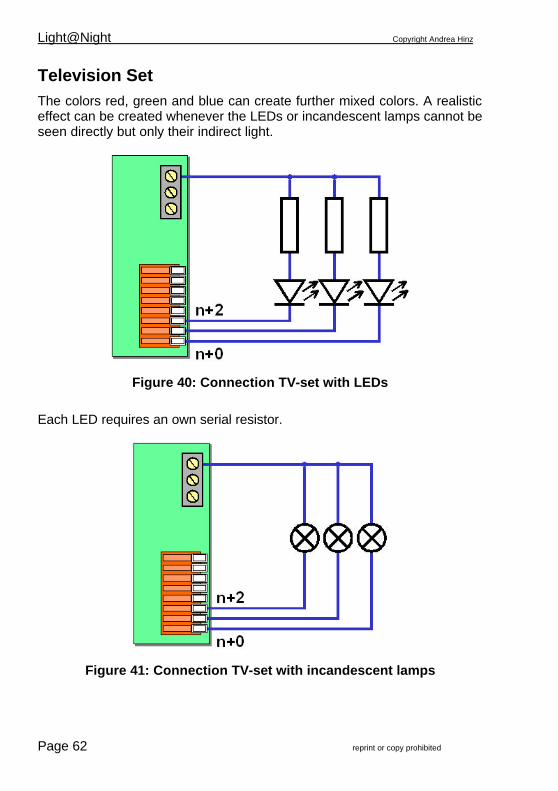
Television Set The colors red, green and blue can create further mixed colors. A realistic effect can be created whenever the LEDs or incandescent lamps cannot be seen directly but only their indirect light.
Figure 40: Connection TV-set with LEDs
Each LED requires an own serial resistor.
Figure 41: Connection TV-set with incandescent lamps

Copyright Andrea Hinz Light@Night
reprint or copy prohibited Page 63
Output Function Color n+0 TV-Set red red n+1 TV-Set green green n+2 TV-Set blue blue
Rail Crossing At a rail crossing is normally one light on each side of the road. Therefore are totally four LEDs or incandescent lamps required.
Figure 42: Connection Rail Crossing with LEDs
Each group of LEDs requires an own serial resistor.

Light@Night Copyright Andrea Hinz
Page 64 reprint or copy prohibited
Figure 43: Connection Rail Crossing with incandescent lamps
Output Function color n+0 rail crossing left red n+1 rail crossing right red
Gas Street Lamp The effect of a gas street lamp belongs to the software with the uppermost effort. In some exceptional cases whenever many gas street lamps are switched-on at the same time it can happen that an aged slow computer will cause a considerable flickering of the dimmed light. Reason for this effect is probably a slow graphics card at the PC. A simple measure will solve the problem: reduce the size of the Light@Night main window into the task bar. Now no graphic software will be required and the PC works faster.
Firework Effects There are three different firework effects available. Each of them occupies 2 outputs. After switching-on either one or both outputs will flicker for a short period. This process will recur after a coincidental pause time until switching-off.

Copyright Andrea Hinz Light@Night
reprint or copy prohibited Page 65
If there is DirectX installed on the PC and a sound card with suitable speakers available then a 3D surround firework will be started independently. The sound will continue a couple of seconds after switching off the last light-spot. The light together with the sound will initiate a perfect simulation. Light Spot Description Light Type Qty. firework1 first output switches-on continuously for a short
duration. Then the second output will start flickering. The timing will vary and eventually overlap
LED, incandescent lamp
2
firework2 first output will flicker for a short duration. Then the second output will switch-on continuously. The timing will vary and eventually overlap
LED, incandescent lamp
2
firework3 first output will flicker for a short duration. Then the second output will start flickering. The timing will vary and eventually overlap
LED, incandescent lamp
2
For the effects can be either LEDs or incandescent lamps connected. For the background of a firework is it possible to use an indirect illumination or an artificial sky. For this effect is it rather recommended to use colored halogen lamps, which can be connected to a Light-Power-Module. Or you can make on your own out of plastic some small optical fiber bundles, which shall get a LED at bundled area. The LED will initiate a firework impression. Practical improved configurations consist out of 6 light spots, which will be switched by 2 switch-groups. The first switch-group will be active during the complete firework and will switch the first three light spots. The second switch-group will control the further three points until the end of the firework.
Schwitch group Time firework1 10:00pm - 10:30pm firework2 10:15pm - 10:30pm
Light Spot Output Type Schwitch-Group
1 1 to 2 firework1 firework1 2 3 to 4 firework2 firework1 3 5 to 6 firework3 firework1 4 7 to 8 firework1 firework2 5 9 to 10 firework2 firework2 6 11 to 12 firework3 firework2
The mentioned times are suitable for a time ratio of 60x or 100x.

Light@Night Copyright Andrea Hinz
Page 66 reprint or copy prohibited
Figure 44: Firework with LED
Figure 45: Firework with incandescent lamps

Copyright Andrea Hinz Light@Night
reprint or copy prohibited Page 67
Realistic Illumination at the Model-Railway Layout
As mentioned at another chapter of this handbook a realistic illumination of houses does not relay only to the technical point of view. Probably is it worthwhile to have a night-walk through a residential area and observe the illumination of individual houses. This will need not much time but the observations will help considerable to receive a realistic general impression of the light control. Somebody did this already many times because he had to have a walk with his dog every night or is interested to study relevant photographs in books or magazines. Everybody who has not, should read and attend to these chapters very carefully. Only on very seldom occasions a constant light will burn all night long inside a building. Exceptions could be e.g. a porterhouse, a signal post or a dispatch-control. At a city mostly the police station or the rescue center will be occupied during the night and therefore always be illuminated. But at a factory even with a night shift there is probably no work at every manufacturing hall. Also the offices will be dark during the night. Exceptional of nightly forgers of balance sheets – but those should not be at present on our model-railway layout. Even thinking a little bit about these samples it shows that we could come up to a correct solution for the illumination. Just transfer yourself into the dimension of your miniature population and everything will go right.
House Illuminations The first windows at a residential area will be lightened already before dusk. Related to the shadows of trees or buildings in the neighborhood it can be already dark in some rooms at an early time. Time after time other member of the families will switch lights on. From the beginning of dusk until the time of darkness at about 11pm the apartments and houses should be illuminated. But naturally not on all windows because a house consist of several rooms and not every room will be illuminated. At first the light will be switched-on at the living room, at the kitchen, the corridors and the child’s room. At a normal residential building, no matter if it is a detached house or a multistory apartment building there will be about 20 to 70% of all windows illuminated at a time. When it will become sleeping time more and more windows will be getting dark except the bedrooms for a certain time. It

Light@Night Copyright Andrea Hinz
Page 68 reprint or copy prohibited
will be a question where the people will have their bedrooms? To the side of the street? Within a certain direction? After 11 pm it will be getting slowly dark at a residential street. It does no matter if it will be at the countryside or in a city. Only at the weekend it should be expected that some city-dwellers would enjoy the nightlife for a certain time. Between 2 and 5am nearly all houses will be dark. Only a few “night-shift-worker” will come home from a party, from a visit or from work. They will not use much light. From 5am but at least before dawn there will be life again inside the houses. The first miniature people have to get up and go to work. Their owner is awaiting certainly fresh croissants and the morning newspaper….. Already from this explanation you will now be sure that you cannot just simply push an electric bulb” into a house. In case the base plate of your miniature houses contain already a practical hole for an electric bulb with plastic socket - forget about this!!! For a fair realistic impression you have to implement some more effort. At first you have to take care that no light shows from the inside through plastic parts or adhesive joints. There are three possibilities to prevent this:
• installation of an inside cover made from seamless glued black carton
• painting the inside with a black bituminous paint (paint shop, motor car accessory)
• installation of small cases directly inside in front of the illuminated windows
Certainly you should check the success of the measures before you complete the assembly. For multistorey houses sometimes somebody intends to divide the story’s by inserting a carton on every storey. This will not be sufficient for residential buildings, as not all windows will be illuminated at the same time. And if they would be, you could see from the outside that there are no walls inside. Never illuminated windows should better be darkened and for a realistic impression equipped with curtains. As at the countryside always

Copyright Andrea Hinz Light@Night
reprint or copy prohibited Page 69
curtains will be used, within the city the use of curtains is depending on the interior furnishing of the apartment. Therefore you will find in the city often windows without visible curtains. But be careful: without curtains the observer of your layout can look inside of the house. In this case the house needs floors, walls and eventually furniture and people. Certainly you have made some personal observations or you have some other wishes for the house illumination. Just carry on. The only importance is to receive a fair realistic. For a single situated detached house the light-spots will add-up between 2 and 10. At a multistorey building it can come up easily to a sum of 10 to 40 light-spots. Please resist the temptation to connect several light-spots of one house to one common output of a light control module. In reality it will be very, very seldom that by random the light of the first and the second floor will be switched on at the same time – except probably the stairwell. Such an irregularity will be immediately registered at the subconscious, because this is not realistic. If you connect some light-spots you should do it with houses in the neighborhood or with not simultaneous visible windows. More information can be found at the chapter about `Several Consumers at one output ` on page 42. Although there will be at least one TV-set on each household available the perfectionist should prevent the temptation to install the required light-spots on full-coverage of the area. The overall picture will be disturbed. If you walk at night through a residential area you will notice the flickering of TV-sets only from time to time.
Which type of light is suitable for house illumination? At first there are the most used types of “electric light bulbs” and “house light”. The light bulbs will be simply switched on or off at configured switching times. The house light will be different: the on- and the off- switching times of a light-spot will be delayed at random by 5 to 20 seconds. This will make the configuration of switching times at residential buildings quite easy. Although you have set the switching time for all residential buildings of one street with one switch-group the lights will be switched on and off at different times. Just as in reality. Furthermore there will be the light type “neon lamp” used. Not everyone likes a comfortable illumination. Therefore you can find quite often neon lamps in kitchens, corridors and other rooms. At least a neon lamp will regularly illuminate the garage.

Light@Night Copyright Andrea Hinz
Page 70 reprint or copy prohibited
Very suitable is the type “random”. This type will switch the light at random within certain variable switching times. Therefore is it possible to set the light-spots of a part of the house-illuminations onto “random” for switching the lights from dusk to dawn with only one switch-group. Nevertheless there will be a continuous irregular change of lights happen. There are still the sporadic and the specific light effects missing. To this effect belongs surely the “TV-set”. It contains 3 outputs. Therefore are 3 different lamps required for one television set. Normally there will be lamps with the color red, green and blue used. Instead of green or blue it will be possible to use yellow or white as well. Because of the nightly artificial light with low frequency a TV-screen will appear rather blue. Therefore you should use blue respectively white if possible. LEDs will give you a more realistic effect then incandescent lamps. At one or two areas on your layout there will be probably just now a party going on. Therefore is it possible that you can see occasionally a flashlight of a camera in one of the houses”. But take care: less is much more (effect). Unless there is a crowd of super stars with lots of photographers or probably there will be a fashion show or a professional movie recorded inside the bedroom of a house in the neighborhood or ……. At least it should be mentioned that some people are used to handle with open fire inside their living room. That will be certainly no pyromaniac but an owner of a comfortable open fireplace. Also this effect should be used on very few locations. The type “fire” uses one light spot. For a realistic open fireplace you should use 2 colored incandescent lamps (red and yellow) connected to two module outputs.

Copyright Andrea Hinz Light@Night
reprint or copy prohibited Page 71
Light-type Mode of Operation Output incandescent lamp
simple switching on and off of one output 1
house light coincidental delay of switching for some seconds, despite of same adjustment of switching time e.g. the illumination of all housings of one street will be switched-on or off at different times
1
neon lamp at first coincidental irregular flashing during switching-on. Will remain switched-on; suitable for kitchens or garages
1
random switching on and off by random-control with adjusted minimum and maximum pauses
1
Television set
three outputs for red, green and blue produces coincidental and permanent changing color-, flash- and flickering effects as on a TV-set; light should be indirect visible
3
flashlight photo-flashlight, is simulating a camera with an occasional flashlight, break time will be for every time coincidental
1
fire simulation of an open fire by producing irregular flickering; use two outputs with incandescent lamps for best results
1
Typical Switch-Groups Name Times Mode of Application house1 06:00pm-11:00pm lights inside houses house2 09:00pm-01:00am lights inside houses stair well 07:00pm-11:00pm temporary light at stair-wells; most effective with light-type
`random` during the day
09:00am-05:00pm switching e.g. light at random or flashlight
TV-set 08:00pm-11:30pm simulation of a switched-on TV-set
At the Road Such as the various ness in life can be the scenes on the roads of your model railway layout as well. At many (much warmer) regions most of the life will be lived on and at the roads. Relating to the light control we will start at first with the road illuminations. At small side roads or on pedestrian ways usually “normal electric globes” will be used for the lamps. The lamps are often situated at very dark areas and on longer ways (for midnight walks not suitable) at larger distances. On the entranceways to residential buildings at larger properties there will be mostly more lamps at closer distances installed.

Light@Night Copyright Andrea Hinz
Page 72 reprint or copy prohibited
Such lamps will be switched simply on and off. At an exclusive residential district there will be probably the one or the other house illuminated by floodlights. But now again to the roads.... The three mostly used lamps for road illumination (not the style and kind of pylon) is the neon lamp, the gas street lamp and the gas compression street lamp. The first one will be used mostly at villages and small townships. The roads are probably small and there is not much traffic. At the evening hours there are not many people outside. Even at residential areas in larger towns they use neon lamps for the street illumination. A special feature is certainly the illumination with gas street lamps at some larger towns. Particularly in Berlin you can find many `real gas street lamps` caused by special circumstances of the long time separation of this town. Whenever the gas supply will be turned-on at night at first the gas mantle has to be heated. This will cause an irregular flickering. Then the flickering will stop and the lamp will burn slowly brighter until the full brightness will be obtained. Whoever walked at night on a street, which has been illuminated by gas lamps, has certainly noticed the warm and comfortable light radiation. And something else: the light seems to flicker slightly from time to time. This will be caused by a little fluctuation of the gas pressure. This will naturally be simulated from Light@Night as well. Under the expression of `high pressure gas lamps, gas pressure lamps, xenon lamps` and others you can find various modern street illuminations with extremely high light radiation. Those high efficiency lamps are used often on roads with a high motorcar frequency and highway connections as well as on large parking lots and railway station forecourts. This kind of lamps requires a certain starting time until they get their full brightness. An important note: just for street lamps it is easy to decide to connect several lamps onto one output. Please resist this temptation because with large effort Light@Night supplies an individual light effect to each output. Particular this feature will give the light effects on your layout a special exemplary image. For explanation: have you ever seen 10 neon lamps flickering simultaneous during switching on?

Copyright Andrea Hinz Light@Night
reprint or copy prohibited Page 73
Also on the roads are many actions. Not only motorcars are traveling but also it should be impressive to illuminate the standing cars. It is possible to switch sporadic the direction indicator lamps on some cars. At dusk there should be the headlights and back lights switched on. For this purpose is a large assortment of light emitting diodes available and can be purchased by mail order by Reichelt or Conrad. For backlights and flashing lights the use of red or yellow miniature light emitting diodes is recommended. The light-spot” should be set to flashing light. From time to time it has to be switched on or off from one or two switch-groups. Time setting could be about 10 to 20 minutes. White light emitting diodes with high light output would be suitable for the front headlights. Only one switch group will switch-on all motorcar headlights at dusk and off at beginning of dawn. To prevent that all cars will switch the lights on at the same time the light type should be set to “random”. This setting will delay the time of switching the lights on as well as the time of switching off. Therefore is a switching sequence at random assured. To connect the thin lacquered copper wire to the little light emitting diodes needs a little care but the result will be excellent. (do not forget the matching serial resistors for light emitting diodes) Operation vehicles (e.g. police, fire brigade etc.) or the garbage collector vehicle will carry certainly an orange or blue operation light on top. These circulating lights have mostly a motor driven mirror inside. Therefore the speed of the motor initiates the frequency of the on- and off-switching. As the frequency is not equal, the operation lights will flash sometimes synchronous and sometimes not. This will be exemplary simulated. Many vehicles of the fire brigade or the ambulance carry additionally a flashlight at the front. They will flash once followed by a little longer pause. Very similar to a stroboscopic light. The operation lights of a police car require therefore two outputs with light-spots as “operation light”. Eventually is a further output required for the front flashlight. Sometimes the inside lights of parked motorcars or trucks will be switched on. Probably the driver has a look at the street-map or he is making a break and has a snack. Perhaps he just wants to leave the car or somebody will get into the car at a disreputed road. The light type “random” is particularly suitable for the occasional switching of the inside lights of a vehicle.

Light@Night Copyright Andrea Hinz
Page 74 reprint or copy prohibited
As more life will be on the roads of a model railway layout as sooner will be a regulation of the traffic required. Therefore we need traffic lights! Light@Night knows two different basic types (type of traffic lights with some further variations. At first are there the simple pedestrian traffic lights: ”traffic light simple”). It requires three outputs for the traffic light control and two outputs for the pedestrian lights. The duration for the red- and green-phases can be adjusted. After shifting the pedestrian lights to red there is certainly a pause before the motorcars get green for the start. As second light type is the “traffic light cross road“ available. It controls the traffic at a cross road including the pedestrian lights. This light type can control a junction road as well. This light type requires in total 6 outputs each for the roads and further 4 outputs for the pedestrian lights. That adds up to a requirement of 10 outputs. The wiring can be found on page 58. If you want to use Light@Night together with the model railway control Railware, a motorcar control or other electronic systems, you can certainly synchronize the traffic lights with the motor car-, tram- or railway traffic as well. Some times there are vehicles (or other equipment) at the roadside indicated by a short red flashlight. The light type “flashlight“ produces exact this effect. With a little imagination it should be certain to find many other scenes for the application of light types from Light@Night. It could be a burning garbage tray or a burning motorcar, a pedestrian gives somebody light for his cigarette or many, or many others.

Copyright Andrea Hinz Light@Night
reprint or copy prohibited Page 75
Type of Lights for Street Illumination Type of Light Mode of Operation Outputs incandescent lamp
simple switching on and off of one output 1
neon lamp at first coincidental irregular flashing during switching-on; will remain switched-on
1
gas compression street lamp
simulation of modern street lamps, produces at first flickering then a longer time dimmed and flickering brightness and then full brightness
1
gas street lamp at first is it flickering some time, then is it dimmed up until full brightness with slight regular flickering, during the normal lighting simulation influenced by occasional irregular and short interruptions caused by fluctuation of the gas
1
random switching on and off by random control with adjusted minimum and maximum
1
Type of Lights at the Road Side and at the Car Traffic Type of Light Mode of Operation Outputs flashing light produces on- and off-switching time of equal duration; the
flashing frequency will differ slightly by every flashing light and every start
1
operation light, operation flashlight
for action vehicles; every light at each start with coincidental selected flashing time simulates the motor drive with different speed”; also for front flashlights: two times a short flash and then a pause
1
welding arc coincidental controlled flickering of a welding process, the duration of the welding with irregular flickering of the welding arc and with a following pause will be determined coincidentally for each sequence
1
random switching on and off by random with adjusted minimum and maximum pauses
1
automatic flashing light
produces typical flashing frequencies for direction indicators of motor cars, slight variation of flashing frequency at every start
1
rail crossing typical flashing of lights at rail crossings with two contrary switched outputs
2
traffic light simple, traffic light on demand, traffic light road crossing/intersection
produces all phases with exemplary pauses and option of “sleeper position”; also for cross roads and junctions; permanent night light with flashing yellow light for the minor road; optional direct jump from red to green
5 5 10

Light@Night Copyright Andrea Hinz
Page 76 reprint or copy prohibited
Type of Light for other purposes Type of Light Mode of Operation Outputs function switches on and off; suitable for wind turbines, mills, motors
foreign light modules, smoke generators, sound modules or MP3 players
1
building site suitable for light chains on building sites, the switched-on time is very short and simulates flashlights, after each sequence there will be a short pause
5
light chain consists always of 4 outputs which will be switched on in succession for an adjustable time
4
flashing light produces on- and off-switching time of equal duration; the flashing frequency will differ slightly by every flashing light and every start
1
radio tower produces flash effects as used by radio- and TV-towers and other high buildings, each time a single short flash with following longer pause
1
chimney produces flashlights as used by chimneys with short dual flash-effect and then a longer pause
1
fire simulation of an open fire by producing irregular flickering 1
Typical Switch-Groups Name Times Application main road 1 06:00pm-08:00am switching the lights at a main road main road 2 06:00pm-01:00am
05:00am-08:00am switching light at the important night times only
minor road 07:00pm-01:00am lights at the minor roads building site 08:00am-05:00pm lights and working equipment at a building site. operation 09:00am-10:00am
12:00am-01:00pm 07:00pm-08:00pm
operation of fire brigade, police or emergency ambulance
working 07:00pm-11:00pm temporary light at stair wells; best effects with light type “Random”
motorcar 07:00pm-11:00pm 07:00am-09:00am
switching e.g. head lights or inside illumination

Copyright Andrea Hinz Light@Night
reprint or copy prohibited Page 77
Day of an open door at our industrial area: Every year our big industrial factories open their facilities during one-day for public visitors. In this case I think we should discuss about our automobile- and our sugar manufacturer. I was very curious about all the changes! Therefore I intended to see personally the alterations! I decided to go to the automobile manufacturer right away in the morning because I expected there many visitors. At the afternoon I planned to go to the manufacturer of sugar from sugar beet. Arriving at the automobile manufacturer I noticed the automatic crossing barriers with light signs at the entrance. Everything worked automatically by push buttons from the entrance. At the production line I saw a plant loc with flashing lights on top carrying some wagons and collecting wagons loaded with automobiles. Interesting was that the loc carried not only one flashlight on top but also several flashlights around. Additionally a warning signal sounded during driving at the facility. Next to the show-hall I could see some forklifts equipped with flashlights hooting once every time they drove in- or outside of the hall. Some robots doing some difficult and heavy work just on their own where particular interesting. They cutted metal parts with a laser and welded complete motorcar chassis together. They carried heavy burden metal parts around! Good heaven that the machines do this work. At the afternoon I arrived at the sugar manufacturing plant. In difference to the automobile manufacturing plant I was fascinating about the modern delivery of sugar beets by rail. At half hour intervals the trains arrived. The plant-locs, as well as DB locs of BR 211 and 212, carried many wagons to the station and carried them unloaded back. Naturally nearly everything works fully automatically. Wagon after wagon traveled via an automatic weighting scale up to the unloading silo. There a water jet or a claw-arm opened the bar-locks of the doors. Then a water jet has unloaded all sugar beets and at the same time the wagon has been cleaned. The same happened parallel with truck deliveries.

Light@Night Copyright Andrea Hinz
Page 78 reprint or copy prohibited
At every event or at every new clearance action there started warning lights or flashing lights. Additionally they’re where loudspeakers released by accidental contacting the light/laser barriers by a person. Strong light beams to illuminate the area by night and day had illuminated the plant. The chimney of the sugar manufacturing plant smoked and over the whole roof there where several pipes releasing much vapor and smoke. This is a brilliant expression for a model-railway layout.
Type of Lights for Industrial Purposes Type of Light Mode of Operation Outputs incandescent lamp
simple switching on and off 1
function switches on and off; suitable for wind turbines, mills, motors foreign light modules, smoke generators, sound modules or MP3 players
1
random switching on and off by random control with adjusted minimum and maximum pauses
1
building site suitable for light chains on building sites, the switched-on time is very short and simulates flashlights, after each sequence there will be a short pause
5
light chain consists always of 4 outputs which will be switched on in succession for an adjustable time
4
flashing light produces on- and off-switching time of equal duration; the flashing frequency will differ slightly by every flashing light and every start
1
radio tower produces flash effects as used by radio- and TV-towers and other high buildings, each time a single short flash with following longer pause
1
chimney produces flashlights as used by chimneys with short dual flash-effect and then a longer pause
1
fire simulation of an open fire by producing irregular flickering 1 welding arc coincidental controlled flickering of a welding process, the
duration of the welding with irregular flickering of the welding arc and with a following pause will be determined coincidentally for each sequence
1
flashlight photo-flashlight, is simulating a camera with an occasional flashlight, break time will be for every time coincidental
1
floodlight needs about half a second for persistence during on- and off-switching
1

Copyright Andrea Hinz Light@Night
reprint or copy prohibited Page 79
Typical Switch-Groups Name Time Application office1 07:00am-09:00am
05:00pm-09:00pm switching lights on at offices
office2 06:30am-08:00am 04:00pm-07:30pm
switching lights on at offices at different times
factory1 05:00am-11:00pm various lights at a factory factory2 06:00pm-09:00pm various lights at a factory (day time) welding 09:00am-09:30am
10:00am-11:00am 02:00pm-02:30pm 04:00pm-05:30pm
welding work at day time
working 07:00am-07:30am temporary lights on operation machines, flashing and other effects
street 06:00am-09:00pm switching road illumination of an industrial area

Light@Night Copyright Andrea Hinz
Page 80 reprint or copy prohibited
At the Railway Station Once I had a meeting at a far distance and I preferred that time to travel by railway because the Inter-City train would be much faster. In the morning at 4:50 I drove to the railway station and discovered again many actions, which could make sense for using them within the light-control of my model-railway layout. At our small township the streets had been slightly illuminated by neon street lamps because of heavy fog. One lamp just flickered, as if it would be switch-on just in the next moment. The new gaslights give a better light. This light is white and much brighter and details can be much better seen during fog. A most striking light illuminated particularly a pedestrian crosswalk. Lamps with orange gaslight assured the best sight. For the upper-most attention two orange warning lights flashed. At the secondary road some motor cars and trucks passed me. From time to time I was disturbed because of the very late dimmed headlights of the passing vehicles. Fortunately the vehicles have direction indicators. This assured me to recognize who will drive where. Just now the automatic window shutters went up at a small snack bar. The owner switched-on the lightened advertising signs at the wall outside the snack bar showing doner kebab and French fries with mayonnaise. At a distance I could recognize the railway station with the bright illuminated station forecourt and the platform hall. Now quickly through the heavy traffic: direction flashing and flashing warning lights from motor cars just stopping at the side of the road, pedestrians with some funny looking flashing shoes or flashing caps or coats with warning lights. Some skateboarder where crossing the street with having `neon-lights` at the rollers. Finally I found a parking lot for my motorcar and switched-off all lights. Our old railway station looked very pretty as it was illuminated by some floodlights. The station looked very big after the renovation and the nightly illumination. I went quickly to the ticket automat which had a colored display and illuminated keys. I got my ticket and went to the train already standing at the platform. The BR 143 with a red taillight pushed our bright illuminated double-decker coach out of the station.

Copyright Andrea Hinz Light@Night
reprint or copy prohibited Page 81
Type of Light at the Railway Station Type of Light Mode of Operation Outputs incandescent lamp
simple switching on and off 1
house light coincidental delay of switching for some seconds, despite of same adjustment of switching time e.g. the illumination of all housings of one street will be switched-on or off at different times
1
neon lamp at first coincidental irregular flashing during switching-on; will remain switched-on; suitable for kitchens or garages
1
random switching on and off by random-control with adjusted minimum and maximum pauses
1
gas compression street lamp
simulation of modern street lamps, produces at first flickering then a longer time dimmed and flickering brightness and then full brightness
1
flashing light produces on- and off-switching time of equal duration; the flashing frequency will differ slightly by every flashing light and every start
1
fire simulation of an open fire by producing irregular flickering 1 welding arc coincidental controlled flickering of a welding process, the
duration of the welding with irregular flickering of the welding arc and with a following pause will be determined coincidentally for each sequence
1
Typical Switch-Groups Name Times Application station forecourt
07:00am-09:00am 05:00pm-09:00pm
switching the lights at the station square
building 06:30am-10:00am 04:00pm-01:30am
switching of lights inside the railway station
shops 05:00pm-11:00pm lights at shop windows at the station factory2 09:00am-05:00pm various lights at a factory (during the day) station hall 05:00am-09:00am
04:00pm-01:00pm switching the light at the station hall
platform 05:00am-01:00am for the illuminations at the platform. working 09:00am-09:30am
10:00am-11:00am 02:00pm-02:30pm 04:00pm-05:30pm
for e.g. temporary working machines
slow drive section
10:00am-10:30am 02:00pm-05:00pm
switching occasionally the flashing lights at a slow proceeding area; but better controlled with Railware released by traveling trains

Light@Night Copyright Andrea Hinz
Page 82 reprint or copy prohibited
At the Railroad Embankment Just imagine we would travel with a slow train, this is naturally a regional train, and very relaxed we are looking out of the window enjoying the pretty sight. Certainly we would concentrate this time onto the illuminations to observe the various different light effects at the embankment. Immediately after the departure from the railway station I saw that we passed the flashing monitoring signal” with a white and yellow lamp. This should give the train driver the signal that the rail crossing ahead works correct. Just then I saw already the flashing lights of the diagonal crosses (Andreas-crosses) at the rail crossing. During the train journey through the countryside everything was quiet peaceful. Only at a far distance some lights from motorcars and suddenly a flashing blue light from a police car could be seen. After a time we passed some villages without a railway station where I could notice the well-known lights at the houses and the street illumination. Decorated by some nicely illuminated advertising signs as well as the big `M` of the restaurant with the golden archways and other factory illuminations. Now it became more interesting! We came into the city and to the central railway station. Just at the entrance-turnouts there flickered a neon lamp supposed to illuminate the station name sign, which refused to lighten up followed by various neon lamps at the operation facility and at the station front-end. At a little distance inside an operation facility with open doors some repair work on locs and coaches with some welding processes could be seen. Next to the working area was a fire burning or something heated in an old metal barrel. At the outside area some workers controlled with lamps something below a passenger car. A man gave some red and green light signals to the train driver of a shunter.

Copyright Andrea Hinz Light@Night
reprint or copy prohibited Page 83
Behind the operation facility where the platforms. Now all lights had been switched on. Some lightened platform cabins and other rooms could be seen. Some of them probably not used any more and therefore not illuminated. Many signs where illuminated. As the train stopped I could see some train information boards with changing illuminated information. At the opposite platform gave an area manager with his signaling disc green light for dispatch. His signaling disc was illuminated which is rather a rare gadget. This seemed to me very effective at my model railroad if a miniature railroad official keeps a signal disc with a little light emitting diode in his hands. At the departure from the central railway station you could see a fair ground at a distance. There you could see lights sparkle and flashing! Someplace you could see already some shiny and flashing Christmas decoration. That made up a pleasant feeling. Passing all this sea of lights I could see now a gigantic flame. It seemed to be that gas from a sewage plant has been burned off. Following I saw a pithead and a tower of a mine with countless lights. Some flickering and on top a red warning light flashing. Then we passed the big signal post. At the lower part one room was illuminated. Inside the signal post some screens flickered and a sea of little light spots indicated positions on the large control board at the wall. You could easily imagine how many train performances would be controlled from this place. Incredible what can be seen at night ! Before I had to leave the train at the next railway station we had to pass a slow-drive section because of a building site. Yellow circular lights had been installed at regular distances directly next to rail embankment. These lights would be switched on during a train performance. They warn the worker about the approaching trains. In the past some guards warned the workers with compressed-air horns.

Light@Night Copyright Andrea Hinz
Page 84 reprint or copy prohibited
Type of Lights at the Railroad Embankment Type of Light Mode of Operation Outputs incandescent lamp
simple switching on and off 1
house light coincidental delay of switching for some seconds, despite of same adjustment of switching time e.g. the illumination of all housings of one street will be switched-on or off at different times
1
neon lamp at first coincidental irregular flashing during switching-on; will remain switched-on; suitable for kitchens or garages
1
random switching on and off by random-control with adjusted minimum and maximum pauses
1
rail crossing typical flashing of lights at rail crossings with two contrary switched outputs
2
flashing light produces on- and off-switching time of equal duration; the flashing frequency will differ slightly by every flashing light and every start
1
signal post one output each in red, yellow and green for the control of LEDs or incandescent lamps which will produce light effects as on a control desk of a signal post
3
welding arc coincidental controlled flickering of a welding process, the duration of the welding with irregular flickering of the welding arc and with a following pause will be determined coincidentally for each sequence
1
Typical Switch-Groups Name Times Application building 06:30am-10:00am
04:00pm-01:30am switching of lights at offices
workshop 05:00am-09:00am 05:00pm-11:00pm
light at the inside of an operation area
working 09:00am-09:30am 10:00am-11:00am 02:00pm-02:30pm 04:00pm-05:30pm
for e.g. temporary working machines
slow drive section
10:00am-10:30am 02:00pm-05:00pm
switching occasionally the flashing lights at a slow proceeding area; but better controlled with Railware by traveling trains

Copyright Andrea Hinz Light@Night
reprint or copy prohibited Page 85
Building Site At a building site there are mostly many actions going on. And by so many actions there is certainly light required. Let us start again with the illumination of a building site . Besides the typical single incandescent and neon lamps (light type incandescent lamp and neon lamp) there are often large floodlights. Light@Night produces a dimmed-on and off switching effect. The building site illumination will be switched-on where and when it will be getting dark or dim. This will be certainly between the usual working hours only. This will be mostly between 5am and 9am as well as between 4pm and 7pm. This depends of the season and the size of the building site. Sometimes there will be work at night. As larger the building site as higher the probability that work will done at night. For this circumstance the corresponding switching times have to be configured. At many building sites there are some lights switched-on during the whole night. This should possibly prevent that somebody `will bring` his tools or material to the building site. At some places there will be welded. Fortunately Light@Night offers this effect as a light type. Also here applies: one welding arc on each building site is sufficient. At many building sites and particularly at road building sites we find illuminated barriers as protection. The lamps are flashing individual or they are connected to light chains. For the individual flashing building site light you will need one output from the Light-Interface, which has been assigned to the light type „flashing light“. If there are several lamps on one protection barrier you could e.g. control them with the light type “light chain”. This type requires always 4 outputs, which will be switched-on in succession. Much better is it to use the type “building site”. This type requires 5 outputs and will switch regular and in succession as a flash. This creates a stroboscopic effect as used at a road detour at a high way. And how are the lights on the vehicles? Many typical building site vehicles have circular lights, which can be very good controlled with the light type “operation light”. For each incandescent lamp or LED a separate output has to be used to receive the typical asynchronous flashing effect of the irregular running motor driven circular lights. Many vehicles contain bright floodlights for the site illumination. If several vehicles carry floodlights those can be controlled in pairs and per vehicle by the light type “house light”.

Light@Night Copyright Andrea Hinz
Page 86 reprint or copy prohibited
Then only one switch-group will be required for all building sites. Nevertheless the floodlights will never be switched simultaneous on or off but with a coincidental delay . Also cranes will be at a building site. At night they require a red permanent light for identification. It is only required to configure the light type “incandescent lamp” for switching.
Type of Light for Building Sites Type of Light Mode of Operation Outputs incandescent lamp
simple switching on and off 1
neon lamp at first coincidental irregular flashing during switching-on; will remain switched-on; suitable for kitchens or garages
1
floodlight needs about half a second for persistence during on- and off-switching
1
welding arc coincidental controlled flickering of a welding process, the duration of the welding with irregular flickering of the welding arc and with a following pause will be determined coincidentally for each sequence
1
flashing light produces on- and off-switching time of equal duration; the flashing frequency will differ slightly by every flashing light and every start
1
light chain consists always of 4 outputs which will be switched on in succession for an adjustable time
4
building site suitable for light chains on building sites, the switched-on time is very short and simulates flashlights, after each sequence there will be a short pause
5
house light coincidental delay of switching for some seconds, despite of same adjustment of switching time e.g. the illumination of all housings of one street will be switched-on or off at different times
1
operation light for action vehicles; every light at each start with coincidental selected flashing time simulates the motor drive with different speed
1

Copyright Andrea Hinz Light@Night
reprint or copy prohibited Page 87
Typical Switch-Groups Name Times Application building site1
07:00am-09:00am 05:00pm-07:00pm
switching some lights at building sites
building site2
06:30am-08:30am 02:00pm-04:00pm 07:00pm-08:00pm
switching further lights on building sites but a different times
work1 10:00am-05:00pm various lights and working machines work2 12:00am-02:00pm
04:00pm-07:00pm lights and working machines at different times
welding 09:00am-09:30am 10:00am-11:00am 02:00pm-02:30pm 04:00pm-05:30pm
welding work at daylight
vehicles 06:00am-09:30am 04:30pm-07:00pm
temporary light on operation machines, floodlights, flashing and other effects
street 06:00am-10:00am 04:00pm-08:00pm
illumination of building sites

Light@Night Copyright Andrea Hinz
Page 88 reprint or copy prohibited

Copyright Andrea Hinz Light@Night
reprint or copy prohibited Page 89
Remote Control with HSI-88
Each single light spot of each switching-group can now be optional switched-on or off by contact, push-button or switch. For this option is it required to connect a RM-DEC-88 Module (or 100% compatible). Up to 4 modules can be connected with the s88 bus cable to the HSI-88 interface for the connection to the PC via a serial interface. In total is it possible to connect up to 64 push-buttons or switches.
Littfinski DatenTechnikD-25492 Heist
www.ldt-infocenter.com
Littfinski DatenTechnik
High Speed Interface 88
HSI-88 Rev. 2.1
Computer
RIGHTMIDDLELEFT
s88 Rückmeldebuss88 feedback bus
KL1
14..18V~
Digital-Profi werden!
Schnelles Computer-Interface für den s88-Rück-meldebus. Ermöglicht 3 Rückmeldestränge.
High Speed Interface-88HSI-88
RS232
br. gelb
109 11 8765432112 13 14 15 16
Peter Littfinski DatenTechnik
Rueckmeldedecoder RM-DEC-88 16-channel feedback modul Rev. 3.0
rosa
gelbgruenbraunw
eiss
grau
INOUT
ST1
ST2
Digital-Profi werden!
16 Rückmeldeeingänge für den s88-Rückmeldebus.
Littfinski DatenTechnikD-25492 Heist
www.ldt-infocenter.com
RückmeldemodulRM-DEC-88
S88- RückmeldebusS88- feedback bus
OUT IN
Computer RS232
OUT IN
Vom ModellbahntrafoFrom transformer
braunbrown
gelbyellow
LEFT
109 11 8765432112 13 14 15 16
Peter Littfinski DatenTechnik
Rueckmeldedecoder RM-DEC-88 16-channel feedback modul Rev. 3.0
rosa
gelbgruenbraunw
eiss
grau
INOUT
ST1
ST2
Digital-Profi werden!
16 Rückmeldeeingänge für den s88-Rückmeldebus.
Littfinski DatenTechnikD-25492 Heist
www.ldt-infocenter.com
RückmeldemodulRM-DEC-88
OUT IN
109 11 8765432112 13 14 15 16
Peter Littfinski DatenTechnik
Rueckmeldedecoder RM-DEC-88 16-channel feedback modul Rev. 3.0
rosa
gelbgruenbraunw
eiss
grau
INOUT
ST1
ST2
Digital-Profi werden!
16 Rückmeldeeingänge für den s88-Rückmeldebus.
Littfinski DatenTechnikD-25492 Heist
www.ldt-infocenter.com
RückmeldemodulRM-DEC-88
OUT
Figure 46: Connection of switches and push-buttons
All RM-DEC-88 have to be connected to the socket `left`of the HSI-88. To enable Light@Night to execute the require action is it required to enter the addresses of the push buttons at the software. An address consists of a module- and an address number. The first module directly connected to the HSI-88 receives the number 1 and the next the number 2 and so on. The connection numbers are always 1 to 16.

Light@Night Copyright Andrea Hinz
Page 90 reprint or copy prohibited
For `Options` and `Interface` has at first the Com- port of the HSI-88 to be indicated. Otherwise are the adjustments for the addresses of the push buttons not visible. Interface Hardware Type of hardware Interface Only Light@Night loaded on the PC Test OK interrupt
Figure 47: Configuration of the HSI-88 Interface
If a push button shall switch single light-spots is it required to enter its address at the configuration adjustments. For this adjustment click on the required light spot and enter the address.
Figure 48: Push button address for light spots (at the right edge)
If a switch-group shall be remote controlled is it required to enter the address of the release push button at the dialog for switch groups at the right side next to the name.

Copyright Andrea Hinz Light@Night
reprint or copy prohibited Page 91
Switch Groups Switch Groups Switching times: push button
Switch Group On Off Description
Red
White
Blue
Push Button
Push Button Auto
Figure 49: Push button address for switch groups
Light@Night identifies on its own if it is a quick-action switch or a switch with continuous contact. If a contact will be activated for a shorter duration as 3 seconds this contact will be identified as quick-action switch. For a switched duration of 3 seconds or longer the identification will be as continuous contact. Therefore are all kind of contacts are suitable for Light@Night. The quick-action switch will switchover the status of a switch-group by each switching contact. Therefore from `On` to `Off` or vice versa. During a continuous contact the light spot will be switched-on as long as the contact will be closed. Therefore `On` by contact closing and `Off` by contact opening. Example:
• You can speficically switch the illumination of single housings, factory sites or streets without make use of the PC.
• A traveling train can release a grade-crossing gate or switch-on a building-site illumination (by using Railware this effects can be switched by the software).
• You can switch specific functional models.

Light@Night Copyright Andrea Hinz
Page 92 reprint or copy prohibited
• Traveling cars (Faller Car-System) can switch traffic lights or release a radar flash.
• You can switchover from daylight to night (suitable switch groups will be required).
• And many others ...
Railware 5 customers will probably use the available possibilities for a remote control of Light@Night. By using
the automatic help-functions will it be possible to use various feedback reports and track symbols for the
operation.

Copyright Andrea Hinz Light@Night
reprint or copy prohibited Page 93
Premises Illumination
On many model railway layouts is it presently a common status to use a premise illumination. The layout is easier and cheaper to realize as expected. With the premise light control of Light@Night is it possible to imitate a natural change between daylight and night. A day-night change will be executed between dusk and night as well as between dawn and day. Those times could already be adjusted under `Options` and `Day-time`. At a maximum expansion will be white, blue and red light supported. During daytime will be the white light switched-on and slowly dimmed down or up during the twilight time. The blue light will be switched-on the night time and dimmed down during the twilight time. The red light is switched-on during morning- and evening twilight only. Dusk Dawn White Red BLUE Red Blue White
Figure 50: Twilight phases
It is possible to work with white light only or with white and red light. This is possible by leaving out the respective addresses.

Light@Night Copyright Andrea Hinz
Page 94 reprint or copy prohibited
Premises Light Control Interface X10 Addresses
Address White Address Red Addtress Blue
Slow Interrupt
Figure 51: Configuration of premise light
Light@Night supports both standards X10 and DMX for the control of remote dimmers and switches. The configuration is considerable simple. At first the used system has to be indicated: either Marmitek X10 or for DMX the variances DMX4all or DMX USB. For DMX4all is it required to enter the USB-interface as DMX4all. For X10 and DMX4all is it required to enter a serial Com-interface even when using USB. You can find this information (Com1 to Com16) at the Windows device manager. For Windows-XP under `System control`, `System`, `Hardware`, `Device manager` and `Connections`. Further information can be found at the installation instruction of the manufacturer of the interface. At last you have to the addresses of the used dimmers. As a minimum the address for the color white has to be entered. If no red or blue lights will be used the respective addresses have to be set to `0`. By X10 is it possible to enter the addresses 1 to 16. Additional is a house-code between A and P required. All dimmers have to use the same house-code. By interferences e.g. reported by neighbors is it recommended to change the house-code. For this process all components have to be separated from the power supply. The option `Slow` should only be used

Copyright Andrea Hinz Light@Night
reprint or copy prohibited Page 95
when white light will be used only. The changeover effect will be carried out within 90 seconds and will be free from any steps. By DMX is it possible to enter addresses from 1 to 512. If possible use low numbered coherent addresses. This will accelerate the data transfer. If there is no dimmer independent illumination at the model railway layout room available you should get some independent control units e.g. wall push buttons, control keyboard or infrared- remote control, which should be suitable to the system and additionally to Light@Night. Otherwise you have to have to switch-on your PC probably in the dark. Marmitek X10 X10 is a common semiautomatic standard mainly used in the US. The company Marmitek is producing and selling X10 products for the European market. The most advantage of this system is the simplicity and the low cost and availability of the components. The basic of this system consist of a dimmer and a PC-interface. The PC-interface and the dimmer communicate without cable connection via the power supply system. There are dimmer with 300 Watt and 700 Watt and 22 respectively 120-brightness steps available.
Figure 52: Marmitek USB-Interface CM11

Light@Night Copyright Andrea Hinz
Page 96 reprint or copy prohibited
Figure 53: Marmitek Dimmer LM12
Only a certain slowliness should be mentioned as disadvantage. Therefore is it possible to notice little brightness jumps during switching from day- to night-light. This effect is not noticeable by a dimmer with white light. The dimmer LD11 with 700 Watt is restricted suitable for using it with halogen-transformers (non electronic switchgear). Please attend to the product information of the manufacturer. The switch AM12 should only be used for an additional flash within the weather simulation. Together with the PC- Interface will be an USB- Interface supplied. Please attend to the installation instruction and load-up at first the driver software and after that connect the USB cable. Except the driver-software is no other software required. The program `Home Control` will not be required by Light@Night. By a parallel operation is no communication between Light@Night and X10 interface possible. Technical information to X10: X10 recognizes no absolute brightness instructions but dimming values in percent. Therefore is the initializing of the X10 dimmers during the start of Light@Night required. This process needs about 30 seconds. Please wait until the right light emitting diode at the status line will indicate with `green` that the initiatlizing process has been completed.

Copyright Andrea Hinz Light@Night
reprint or copy prohibited Page 97
The status of the dimmers can be in definable if a running event between day and night will be interrupted or manipulated by remote control. In this case you have to take care to get the basic adjustment of the dimmers. One command needs about 1 second with reason to the X10 slowness. The finest change of brightness will be 1/120. From a certain time factor has the next-lower value of 1/22 to be selected. As this follows mostly to 15 to 20 steps only this will result into considerable visible brightness jumps. As slower the timing runs and as longer the daylight transition has been adjusted (about 2 hours) as less jumps will be visible.
By one color (white) and adjustment `slow` with 120 steps will the duration of the transition require about 120 seconds.
By three colors and 22 steps will be as well 120 seconds required.
The twilight time (within the daylight time) can be 2 hours and the time factor at most 100x. For shorter time factors has to be the twilight phase extended.
Figure 54: Example Marmitek

Light@Night Copyright Andrea Hinz
Page 98 reprint or copy prohibited
DMX This standard bus-system will often be called `Theater-Bus` because it has been developed for the control of stage technique of all kind. Nowadays will be the variance DMX512 used only. There are many manufacturers of dimmer for lamps, neon lamps, halogen-lamps and interfaces for the PC available. DMX is fast, rugged and reliable. Though it is some technical knowledge required as the instructions are rather written for stage technicians than for model railroader. There are generally 255 brightness steps for dimmers available.
Figure 55: USB-Interface from DMX4all
The Mini-USB-DMX from manufacturer DMX4All, the USB2DMX from oKsidiZer or the USB-Interface from Sunlite are suitable PC-Interfaces with USB-connection. DMX4All supplies kits and finished modules for a 6-channel dimmer. For the kits will be extensive electronic knowledge required. For unpracticed model railroader is it recommended to purchase rather the dimmer-pack DDP-405 from Geo Technik or the EDX4 from Conrad. Many further manufacturer supply products for any mode of application at a price range between hundred and some thousand Euro. Please get some relevant information from the Internet.

Copyright Andrea Hinz Light@Night
reprint or copy prohibited Page 99
Figure 56: 6 Channel Dimmer Module from DMX4All
Figure 57: Dimmerpack DDP-405 from Geo Technik
Figure 58: Dimmerpack from Conrad

Light@Night Copyright Andrea Hinz
Page 100 reprint or copy prohibited
Figure 59: Example DMX
Other Systems Further components are known in accordance to the EIB and DALI standards. Those standards are used mostly for extended building installations. For both standards are converters to DMX available. Therefore is it possible to control DALI or EIB dimmers with a simple DMX-USB interface and a suitable converter. Some information and sources of supply: Manufacturer Products Internet Marmitek X10 Products www.marmitek.de DMX4all DMX-Interface, Module www.dmx4all.de Geo Technik DMX Dimmer-Packs www.dimmer.de Sunlite DMX-Interface - SoundLight Various DMX Products - Conrad EDX4 Dimmer Pack www.conrad.de
DMX has no restriction about the speed of the twilight phases
Practical Notes • With reason to speed, quality and efficiency is it recommended to
use the DMX system. • As DMX-Interface we recommend the Mini-USB-Interface from
DMX4all.

Copyright Andrea Hinz Light@Night
reprint or copy prohibited Page 101
• Use low and successive addresses. • Set the clock speed onto a matching value. A factor 50x or 100x
would be suitable. A very fast running clock will initiate non-realistic twilight phases or the rain or thunderstorm will be released to often.
• The twilight phases of X10 are optimized for a time factor of 60x or 100x.
• There will be a slight difference of the minimum brightness values by dimmers of various manufacturers and the connected lamps. Eventually is it required to match the day times and the switch groups to adapt the premise-illumination to the switching times. Keep to the once adjusted time factor.
• For rain or thunderstorm is are minimum values of 0 or 1 and maximum values of 1 recommended.
• At Windows 95 or 98 is often DirectX not installed. In this case will the sound output not work. DirectX can be loaded-up at the Internet for free. Please attend to the terms that over aged operation systems will probably not official supported any more.
• Some systems will set all outputs to zero during the start. If it will be the only light source within the model railway premises the PC with Light@Night should be started at first. You should establish an external possibility to switch the light.
• A very fast switching from daylight to night as well as short start-stop changes can mix-up the system functions. Rather wait until the selected operation has been completed.
• It is recommended to start Light@Night directly during daylight or at the nighttime. If required should be the premise illumination set manually at first.
Attention Main Voltage! Serious Danger for Life!
Installation work at the main voltage shall be carried out from authorized personal only.

Light@Night Copyright Andrea Hinz
Page 102 reprint or copy prohibited

Copyright Andrea Hinz Light@Night
reprint or copy prohibited Page 103
Weather Simulation
The requirement to get an exemplary and alternated weather simulation on a model railway layout is a premise light control, a sound card for the 5.1 surround system at the PC and a suitable loudspeaker system including a big sub-woofer. Then will it be possible to initiate with Light@Night to cover the sunlight with clouds and darken down the premises lights. Sometimes should fall some rain, which can be heared over the loudspeaker system. From time to time should come up a thunderstorm with a considerable darkening of the sunlight and loud thunder and bright thunder strikes. Every day and every thunderstorm will be different because time, sound and light effects will vary. But take attention: not only the miniature people at the model railway will be frightened but probably your neighbors as well. You can set the required options at the menu options at the weather simulation. You can decide if you wish clouds, rain or thunder storm. For rain and thunder storm you can optional switch the sound on or off.

Light@Night Copyright Andrea Hinz
Page 104 reprint or copy prohibited
Weather Simulation
Clouds
Rain
Thunder Storm
Clouds / Rain Min./Day Max./Day With Sound Thunder Storm Min./Day Max./Day With Sound Address of extra Flash Interrupt
Figure 60: Configuration of Weather Simulation
Suitable to a thunderstorm is it possible to create thunder lightening. For these effects are two possibilities available which will be supported at the same time as well. A light spot will be set as a lightening flash. It will occupy always 3 outputs of a light-module. For a short time those outputs will flicker fast and irregular and create therefore a flash-like effect. As always only the first output will be set and all three outputs have to be controlled by one module. It is recommended to use a Light-Power-Module and connect three 12 Volt halogen lamps with 20 Watt each. Attend to a sufficient power supply. Light@Night will find those light spots and will control them independently.

Copyright Andrea Hinz Light@Night
reprint or copy prohibited Page 105
Figure 61: Creating a Flash with a Power-Module
For a X10 premise light control can be a 230 Volt switch module (no dimmer) used for switching-on a stroboscope (to be purchased at low price at mail order firms for electronic components) for about one second.
Figure 62: Creating a Flash with a X10 Switch
By using a DMX- basic premises light control will be three consecutive DMX-addresses used as by a light spot. With a fast and irregular switching-on you will create a flash-like effect of high quality. Suitable are dimmer- or switch modules with DMX connection and various capacity.

Light@Night Copyright Andrea Hinz
Page 106 reprint or copy prohibited
Figure 63: Creating a Flash with DMX Dimmer

Copyright Andrea Hinz Light@Night
reprint or copy prohibited Page 107
The `Finder`
Mostly will be a description of the light spot and the location registered at the comment field. For example: `Bakery 1.Floor` or `Bag-Road 13`. The finder permits to search for single light spots. Either you will enter a partly text of the comments or an output with the format 1.1, 1,1 or 1-1. If one of the three hyphen will be recognized the system will search for an output, otherwise at the comment field. File Edit Weather Options Help Light Spots as a list Objects aligned to pattern Indicate pattern Finder / Central Station
Figure 64: The Finder in Action
The search will be finalized after finding the first matching light spot.

Light@Night Copyright Andrea Hinz
Page 108 reprint or copy prohibited

Copyright Andrea Hinz Light@Night
reprint or copy prohibited Page 109
Interface for other Software (API)
Single light spots can be switched-on or off from other programs. In addition Light@Night can be started, stopped or transferred into one of the four daytimes. Basic of the communication is a network interface. Light@Night keeps open the UDP-Port 11099 during the whole starting time of the application. If there is an own application running on the same computer the local IP-Address 127.0.0.1 has to be used. Otherwise of course the real address of the computer has to be used where Light@Night works. The following datagram’s can be transmitted: Port Cmd Data Description 11099 s setting into Edit-Mode 11099 g setting into Run-Mode 11099 t X setting the daytime.
The data cell X indicates: M=dawn T=day A=dusk N=night
11099 11099 p MMMPPPS switching–on or off a configured light spot.
Indication for data: MMM = three-digit, indication of the module PPP = three digit, port number at the module S = E=switching-on, A=switching-off at MMM and PPP with leading `0`or fill up
Example for valid datagram’s: ‚s’ = Edit Mode ‚g’ = Run Mode ‚p002017E’ = Light Spot 2,17 switching-on ‚p001040E’ = Light Spot 1,40 switching-off ‚tA’ = Dusk starting and if necessary change into RunMode All commands and data are ASCII-Bytes. An ASCII-Byte sequence without further schedule or length indicator has to be transmitted.

Light@Night Copyright Andrea Hinz
Page 110 reprint or copy prohibited
There will be no confirmations or other information’s returned. Nevertheless for setting back the buffer memory it is required to read and react to datagram’s received on this port. However their content shall be ignored. In case you transmit faulty or herewith not-defined datagram’s an unexpected result can occur. There will be no checks for incorrect data performed. Normally faulty data will be refused without comments. In case you require further interfaces or additional functions of Light@Night please contact us ([email protected]). Apart from the described interface there are further proven modules available particularly for the professional range without model railways as e.g. a Light@Night-Engine including several further settings as well as macro-, network- and synchronization functions.

Copyright Andrea Hinz Light@Night
reprint or copy prohibited Page 111
Operating with Railware
If Light@Night will be used together with Railware Release 5 many different possibilities can be used. For example is it possible to switch any light spots or switch-groups on or off by means of the known auxiliary automatic in Railware. All time settings will run independent and synchronized and the automatic functions (e.g. coach light) will be controlled by Light@Night. Details for the configuration can be found at the Web site for Railware 5.
For an adaptation with Railware the version 5 is required
New Railware versions from 5.10 will support the illumination of dispatch tables with Light@Night Modules.

Light@Night Copyright Andrea Hinz
Page 112 reprint or copy prohibited

Copyright Andrea Hinz Light@Night
reprint or copy prohibited Page 113
Future Extensions
The present edition of Light@Night is the beginning of a new world with beautiful light effects at your model-railway layout. Some extensions of the software and supplementary packages for many further light effects will be available soon. For the hardware range we plan to offer further modules and functions. On this way Light@Night will become a modular upgradable system. You can get actual information about all innovations by calling regularly our Web-site: www.Light-at-Night.com.

Light@Night Copyright Andrea Hinz
Page 114 reprint or copy prohibited

Copyright Andrea Hinz Light@Night
reprint or copy prohibited Page 115
Figure Directory
Figure 1: Light-Display with Light-Interface from LDT .............................. 12 Figure 2: Pin bar connection ................................................................... 17 Figure 3: Type of Light Module................................................................ 18 Figure 4: The LDT Light-Power-Module................................................... 19 Figure 5: 40 Watt switched mode mains power supply (Reichelt)............. 20 Figure 6: 150 Watt switched mode mains power supply (Reichelt)........... 20 Figure 7: Correct Module Sequence........................................................ 21 Figure 8: Incorrect Module Sequence...................................................... 21 Figure 9: Correct Module Sequence........................................................ 21 Figure 10: Dialog Switch-Group .............................................................. 23 Figure 11: Dialog Daytime....................................................................... 25 Figure 12: Dialog Lamp Adjustment ........................................................ 26 Figure 13: Help function with mouse-click right / left ................................ 26 Figure 14: Dialog Interface...................................................................... 27 Figure 15: Transformer Connection......................................................... 31 Figure 16: Checking the phase relationship............................................. 32 Figure 17: Wire-end sleeves with pliers................................................... 33 Figure 18: Assembly with wire-end sleeves............................................. 34 Figure 19: Connection of incandescent lamps and LED........................... 34 Figure 20: Different style of lamps........................................................... 36 Figure 21: Different LEDs........................................................................ 38 Figure 22: Dialog Calculate Resistor ....................................................... 40 Figure 23: Three LEDs in series.............................................................. 41 Figure 24: Several LEDs in series ........................................................... 42 Figure 25: Incandescent lamps connected parallel .................................. 42 Figure 26: Connection Light Spot with LED ............................................. 53 Figure 27: Connection Light Spot with incandescent lamp....................... 54 Figure 28: Connection Light Chains with LEDs........................................ 54 Figure 29: Connection Light Chain with incandescent lamps ................... 55 Figure 30: Connection Building Site with LEDs........................................ 55 Figure 31: Connection Building Site with incandescent lamps.................. 56 Figure 32: Simple Traffic Light with LEDs................................................ 56 Figure 33: Simple Traffic Light with incandescent lamps.......................... 57 Figure 34: Allocation of traffic lights......................................................... 58 Figure 35: Connection Cross Road with LEDs......................................... 58 Figure 36: Connection Cross Road with incandescent lamps................... 59 Figure 37: Allocation of traffic lights......................................................... 60 Figure 38: Connection Signal Post with LEDs.......................................... 61

Light@Night Copyright Andrea Hinz
Page 116 reprint or copy prohibited
Figure 39: Connection Signal Post with incandescent lamps ....................61 Figure 40: Connection TV-set with LEDs..................................................62 Figure 41: Connection TV-set with incandescent lamps ...........................62 Figure 42: Connection Rail Crossing with LEDs .......................................63 Figure 43: Connection Rail Crossing with incandescent lamps.................64 Figure 44: Firework with LED...................................................................66 Figure 45: Firework with incandescent lamps...........................................66 Figure 46: Connection of switches and push-buttons................................89 Figure 47: Configuration of the HSI-88 Interface ......................................90 Figure 48: Push button address for light spots (at the right edge) .............90 Figure 49: Push button address for switch groups....................................91 Figure 50: Twilight phases .......................................................................93 Figure 51: Configuration of premise light..................................................94 Figure 52: Marmitek USB-Interface CM11................................................95 Figure 53: Marmitek Dimmer LM12..........................................................96 Figure 54: Example Marmitek ..................................................................97 Figure 55: USB-Interface from DMX4all ...................................................98 Figure 56: 6 Channel Dimmer Module from DMX4All ...............................99 Figure 57: Dimmerpack DDP-405 from Geo Technik................................99 Figure 59: Example DMX.......................................................................100 Figure 60: Configuration of Weather Simulation .....................................104 Figure 61: Creating a Flash with a Power-Module ..................................105 Figure 62: Creating a Flash with a X10 Switch .......................................105 Figure 63: Creating a Flash with DMX Dimmer.......................................106 Figure 64: The Finder in Action..............................................................107

Copyright Andrea Hinz Light@Night
reprint or copy prohibited Page 117
Index
Adapter............................... 9, 27 Area Manager ......................... 83 Auxiliary Automatic ............... 111 Building Site.... 23, 49, 55, 56, 76,
78, 83, 85, 86 Cable............... 11, 12, 32, 33, 40 CD-ROM................................. 15 Central Clock .......................... 46 Control Desk......................50, 84 Day................ 46, 47, 77, 78, 109 Daytime ......... 24, 25, 46, 47, 109 Delay .................................69, 86 Drive Way............................... 60 Dusk ........ 24, 47, 67, 70, 73, 109 Fire37, 50, 70, 71, 73, 74, 76, 78,
81, 82 Flashing Light . 43, 49, 50, 73, 75,
76, 77, 78, 81, 82, 84, 85, 86 Gas Street Lamp...24, 43, 50, 64,
72, 75 Help........................................ 26 House .............. 67, 68, 69, 70, 72 Illumination 35, 36, 67, 69, 80, 85,
87 Incandescent Lamp.....32, 35, 37,
45, 49, 54, 65, 68, 69, 71, 75, 78, 81, 84, 85, 86
Installation .............11, 15, 17, 69 Installation Program ................ 15 Interface . 5, 9, 11, 12, 26, 27, 29,
45, 85, 110 LDT ................... 5, 12, 17, 26, 27 LED29, 34, 37, 38, 40, 41, 42, 49,
50, 51, 53, 54, 55, 61, 62, 63, 65, 70, 85
Light-Display... 12, 17, 31, 32, 34, 35, 36, 45, 49
Light-Interface........11, 12, 45, 85
Light-Spot. 24, 29, 45, 47, 49, 53, 54, 55, 65, 70, 73, 109
Macro ....................................110 Miniature People.......... 67, 68, 83 Network ......................... 109, 110 Night....24, 46, 47, 67, 78, 83, 85,
109 Operation Models ........ 49, 76, 78 Platform....................... 80, 81, 83 Rail Crossing ... 63, 64, 75, 82, 84 Railware ... 1, 5, 9, 25, 46, 74, 81,
84, 111 Railway Station...... 80, 81, 82, 83 Signal Post 50, 60, 61, 67, 83, 84 Simulation ................... 42, 50, 75 Site Illumination .......................85 Speed...24, 43, 46, 49, 73, 75, 86 Status Line ........................24, 46 Switch-Group.. 23, 24, 45, 47, 69,
70, 73, 86 Switching.. 17, 24, 32, 47, 49, 71,
81, 84, 86 System Requirement .................9 Television Set.. 50, 62, 63, 70, 71 Time........................................46 Traffic Light...... 50, 56, 58, 74, 75 Train Driver..............................82 Train Performance...................83 Type31, 38, 69, 70, 73, 74, 85, 86 USB.....................................9, 27 Utilization...................................9 Working Memory .......................9

Light@Night Copyright Andrea Hinz
Page 118 reprint or copy prohibited

Copyright Andrea Hinz Light@Night
reprint or copy prohibited Page 119

Light@Night Copyright Andrea Hinz
Page 120 reprint or copy prohibited