Manual KTX20 V2.0 EN - emri.nlReplacement for Nishishiba & Taiyo AVR’s Instruction Manual V2.0...
16
KTX20 Replacement for Nishishiba & Taiyo AVR’s Instruction Manual V2.0 Product version V2.0.0.0
Transcript of Manual KTX20 V2.0 EN - emri.nlReplacement for Nishishiba & Taiyo AVR’s Instruction Manual V2.0...
KTX20 Replacement for Nishishiba & Taiyo AVR’s
Instruction Manual V2.0
Product version V2.0.0.0
Manual V2.0 Page 2 of 16
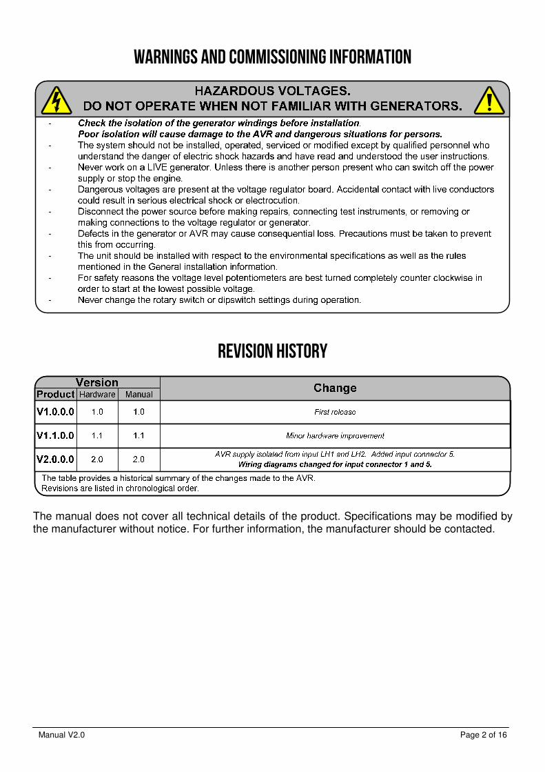
WARNINGS AND COMMISSIONING INFORMATION
REVISION HISTORY
The manual does not cover all technical details of the product. Specifications may be modified by the manufacturer without notice. For further information, the manufacturer should be contacted.
Manual V2.0 Page 3 of 16
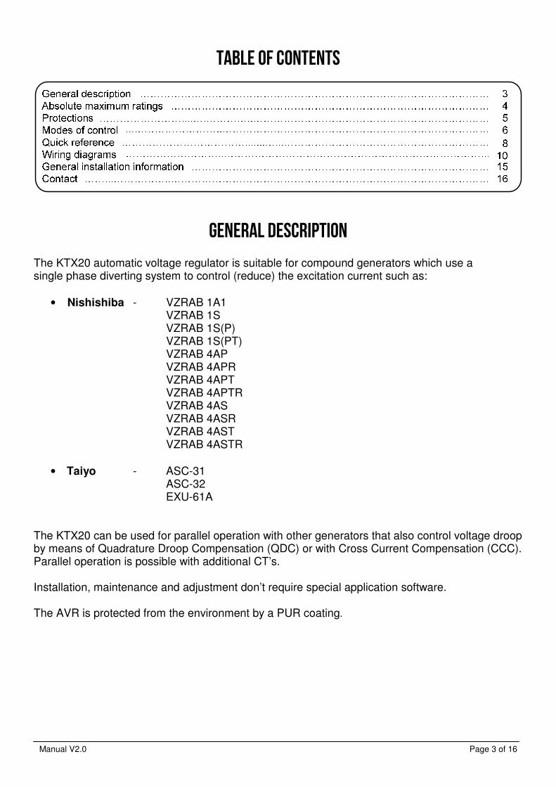
TABLE OF CONTENTS
GENERAL DESCRIPTION The KTX20 automatic voltage regulator is suitable for compound generators which use a single phase diverting system to control (reduce) the excitation current such as:
• Nishishiba - VZRAB 1A1 VZRAB 1S VZRAB 1S(P) VZRAB 1S(PT) VZRAB 4AP VZRAB 4APR VZRAB 4APT VZRAB 4APTR VZRAB 4AS VZRAB 4ASR VZRAB 4AST VZRAB 4ASTR
• Taiyo - ASC-31 ASC-32 EXU-61A
The KTX20 can be used for parallel operation with other generators that also control voltage droop by means of Quadrature Droop Compensation (QDC) or with Cross Current Compensation (CCC). Parallel operation is possible with additional CT’s. Installation, maintenance and adjustment don’t require special application software. The AVR is protected from the environment by a PUR coating.
Manual V2.0 Page 4 of 16
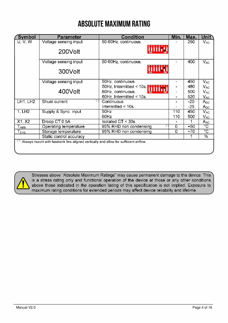
ABSOLUTE MAXIMUM RATING
Manual V2.0 Page 5 of 16
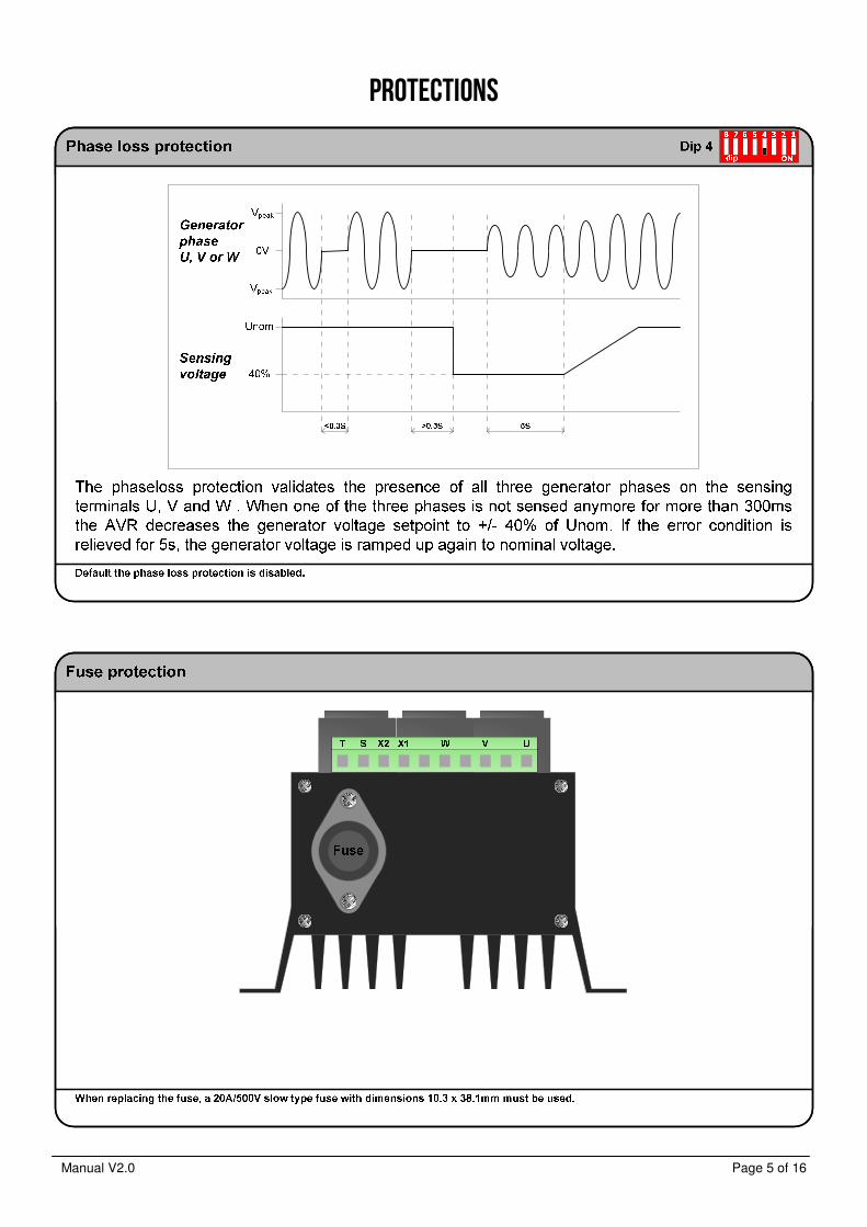
PROTECTIONS
Manual V2.0 Page 6 of 16
MODES OF CONTROL IIII
Generator Load
Unom
Droop
Inominal
D
more
capacitive
more
inductive
Voltage droop
0V0A
(Droop)
Manual V2.0 Page 7 of 16
MODES OF CONTROL IIIIIIII
Sensing voltage
Sensing voltage
Sensing voltage
Manual V2.0 Page 8 of 16
QUICK REFERENCE IIII
Sensing rangeFactory settings
Dipswitch
ON
1234
dip
5678
Not used.
DIP Off On
Not permitted.1
2
3
4
5
6
7
8
Phase loss protection disabled.
Remote adjust enabled.
Not used.
Not used.
Underspeed protection disabled.
Phase loss protection enabled.
Not used.
Not used.
S-T internally shorted.
Underspeed protection enabled.
(Page 6, 7)
Droop
(Page 6)
0% 100%
Underspeed
(Page 6)
LED
+ -
Stability
(Page 6)
- + - +
I-action
(Integral time)
P-action
(Proportional gain)
Voltage
- + - +
FineCoarse
Trip @
Higher – RPM - Lower+/- 65Hz +/- 33Hz
Not permitted
200V
300V
400V
Dip 2 on & Dip3 off
Range +/- 160 .. 250V
Dip 2 off & Dip3 on
Range +/- 250 .. 400V
Dip 2 off & Dip3 off
Range +/- 315 .. 510V
See : Sensing range
When potentiometers in mid position.
Voltage is +/- 195V @ sensing range 200V
Voltage is +/- 305V @ sensing range 300V
Voltage is +/- 390V @ sensing range 400V
Sensing voltage
Underspeed frequency
Droop
Stability P-action
Stability I-action
Dipswitch 1
Dipswitch 2
Dipswitch 3
Dipswitch 4
Dipswitch 5
Dipswitch 6
Dipswitch 7
Dipswitch 8
: 400V
: 47Hz (Underspeed disabled)
: 100%
: 50%
: 50 %
: Off
: Off
: Off
: Off
: On
: Off
: Off
: Off

Manual V2.0 Page 9 of 16
QUICK REFERENCE II
Sensing
U-V-W clockwise
Remote adjust
1kΩ
+-
Max. value : 10K Max. : -10V..+10V
S T
Isolated supply
(-10V .. +10V)
Rx (10kΩ ..100kΩ)
Dipswitch 5 off Dipswitch 5 off
S T
0..10kΩ
Rx
Current sensing
X1 X2
Input X1-X2
CT 0.5A
(Droopkit)
Max. rating :
Continuous : 0.5Aac
Intermitted : 1Aac < 10s.
V phase
0.5A
200V 300V 400V
Compound (Page 10..13)
Single CT with ½ phase Tap Double CT with Full phase
WVU
Kk
L
l
Exciter Field
WVU
Kk
Ll
Exciter Field
Kk
Ll
≤15Ω
Manual V2.0 Page 10 of 16
WIRING DIAGRAM IIII
Nishishiba VZRAB replacement with single CT
Manual V2.0 Page 11 of 16
WIRING DIAGRAM IIIIIIII
Nishishiba VZRAB replacement with double CT
Manual V2.0 Page 12 of 16
WIRING DIAGRAM IIIIIIIIIIII
Taiyo ASC-32 replacement with double CT
Manual V2.0 Page 13 of 16
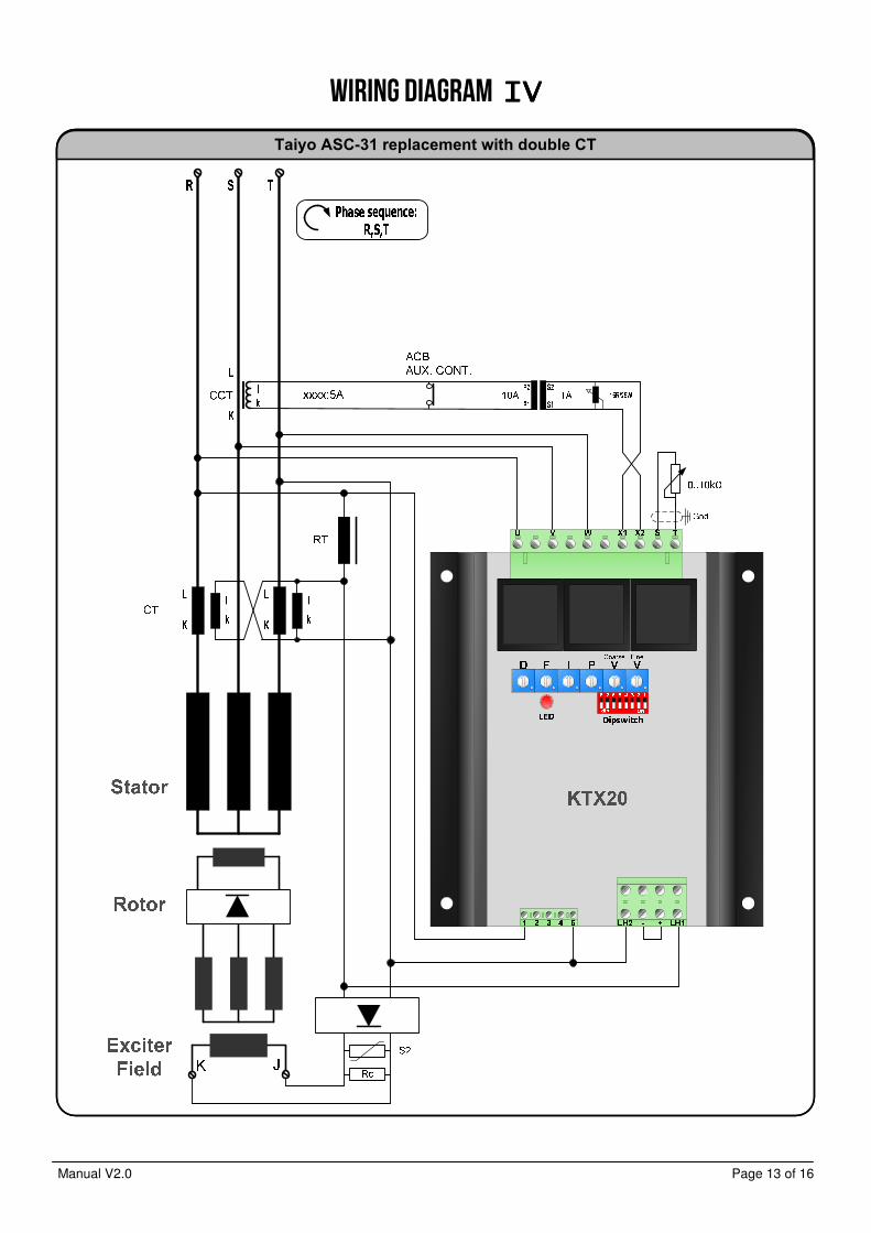
WIRING DIAGRAM IIIIVVVV
Taiyo ASC-31 replacement with double CT
Manual V2.0 Page 14 of 16
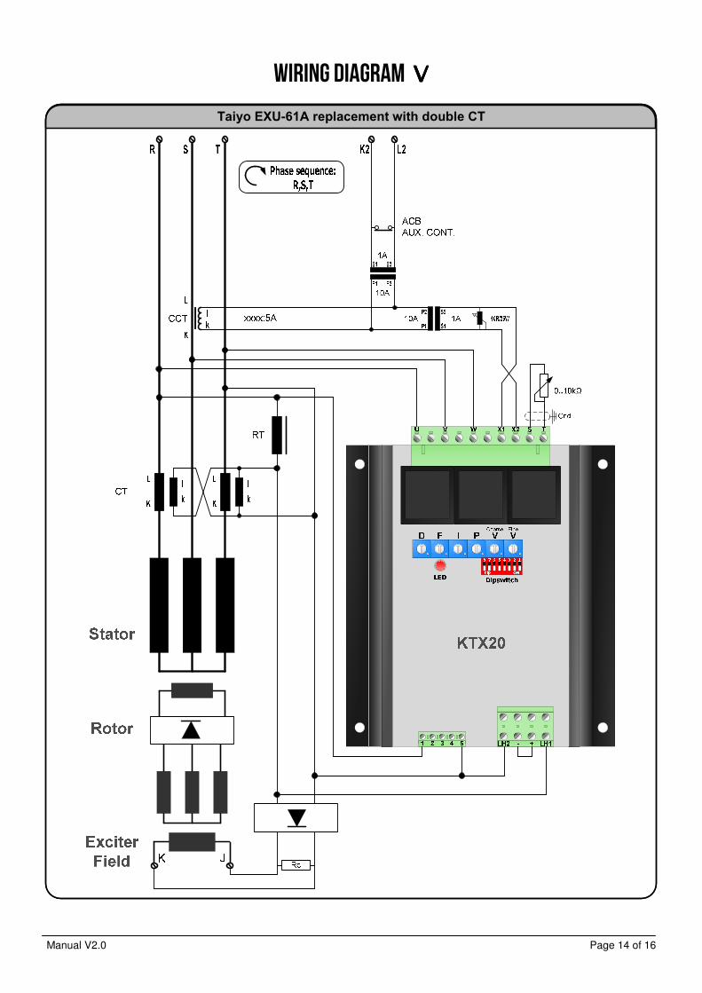
WIRING DIAGRAM VVVV
Taiyo EXU-61A replacement with double CT
Manual V2.0 Page 15 of 16
GENERAL INSTALLATION INFORMATION Absolute Maximum Ratings - The Absolute Maximum Ratings are those limits for the device that, if exceeded, will likely damage the device. Exceeding the
absolute maximum ratings voids any warranty and/or guarantee. Mounting
Mounting of the product should be done in such a way that: - the absolute maximum ambient temperature rating of the product will never be exceeded. - maximum cooling (direction of cooling ribs and direction of airflow) is achieved. - Mounting no humid air can flow through the product or condensation occurs. - dust or other materials or residue will not remain in or on the product. - the maximum vibration is not exceeded. - personal contact with persons is impossible. Wiring - Diameter size of the wiring should be enough to carry the expected current. Wire insulation should be enough to withstand
the expected operating voltages and temperatures. - To improve EMC emission and immunity, care should be taken for the lay out of the wiring. This in respect to all wiring in the
installation. - Keep current carrying wires as short as possible. - Keep wires carrying a total sum of zero Ampere close to each other, or in one single cable, E.g. U, V, W, or J (+) and K (-),
or Phase and neutral, or S and T. - Avoid current carrying conductors next to sensing or control wiring. Especially current controlled by SCR’s or PWM controlled
transistors. - If sensitive sensing signal cables need to be laid across distance along other cabling, shielded cable is preferred. Keep the
shield as long as possible and the wiring outside the shield as short as possible. Do not solder or shrink the shield to a regular wire. Connect the original shield to ground at one side with an as large as possible contact surface.
Additional installation information - When the product is supplied by means of a transformer, it should never be an auto-transformer. Auto-transformers react as
voltage sweep up coil and may cause high voltage peaks. - Standard fit capacitors or over-voltage suppressers across X (+) and XX (-), or exciter field terminals inside the generator
should be removed. - When the product is supplied by means of a transformer, it should be able to carry at least the maximum expected current.
Advisable is, to have a transformer which can carry twice the maximum expected current. Inductive loads make voltage sacks and peeks into the secondary voltage of a transformer, from which the device may malfunction.
- It is not recommended to apply switches in dc outputs. It is preferred to use switches in the ac supply inputs of devices. In case it is unavoidable to have switches in the dc output of a device, action must be taken to avoid over voltage damage to the device due to contact arcing. Use a voltage suppressor across the output.
- It is not recommended to apply switches or fuses in the sensing lines. Defects can cause high voltage situations due to over-excitation.
- When using a step down transformer in medium or high voltage generators, the transformer should be three phase (if three phase sensing), and the transformer should be suitable for acting as a sensing transformer. If the transformer is unloaded, connect a resistor to avoid voltage waveform distortion.
- The phase relation from the generator to the AVR is important. Also when voltage transformers and/ or current transformers are installed.
- When using a step down or insulation transformer in the droop circuit, phase relation from the generator to the AVR is important.
- CT’s wiring, connected to the AVR should never be grounded. - Always disconnect electronic products, circuits and people before checking the insulation resistance (Megger check). - Due to differences in generators impedance’s, EMC behavior is not predictable. Therefore the commissioner / installer should
be aware of proper and correct installation. - Large, highly inductive, exciter stator windings can cause destructive high voltage peaks. Adding a resistor from 10 to 20
times the exciter stator field resistance reduces voltage spikes. If necessary filter can be fitted additionally. (e.g. snubber, RC-network)
- Upon problems during commissioning, faulty behavior or defects in the generator, consult the fault finding manual at our web site
- Some advises may be overdone or seem extraordinary, but since the electrical rules are the same everywhere, these advises are given.
Manual V2.0 Page 16 of 16
Contact
EMRI Electronics B.V. Manufacturer Morsestraat 10 6716 AH, Ede, Netherlands Tel: +31 (0)318 620 427 Website: www.emri.nl E-mail: [email protected]
ICELAND, Hafnarfjordur Rafeining ehf Tel: +354 565 3049 Fax: +354 565 3048 Website: www.rafeining.is
E-mail: [email protected]
POLAND, Gdynia An-Elec Sp. z o.o. Tel: +48 58 668 44 00 Fax: +48 58 668 44 66 Website: http://an-elec.pl E-mail: [email protected]
INDIA, Faridabad
Power Solutions Tel: +91 9868907903 Fax:: +91 129 2431216 Website: www.psolindia.com E-mail: [email protected]
SOUTH AFRICA, Roodepoort
Yneldo Electronics Tel: +27(0)117637053 Fax: +27(0)117634212 Website: www.yneldo.com E-mail: [email protected]
POLAND, Szczecin-Mierzyn
Marel Serwis Tel: +48 91 48 58 388 Fax: +48 91 48 79 948 Website: www.marel.szczecin.pl E-mail: [email protected]
CHILE, Santiago Lucio Vicencio y CIA.LTDA Tel: +1-281-334-2904 Fax:: +1-832-221-5642 Website: www.luciovicencio.cl E-mail: [email protected]
NORWAY, Bergen Frydenbø Electric A/S Tel: +47 55 34 91 00 Fax: +47 55 34 91 10 Website: www.frydenbo.no
E-mail: [email protected]
SINGAPORE, Singapore Cyclect Electrical Engineering Tel: +65 6868 6013 Fax: +65 6863 6260 Website: www.cyclect.com.sg E-mail: [email protected]
THAILAND, Bang Lamung Semtec Maritime/Genetech Co.Ltd Tel: +66 38301262 Fax: +1-832-221-5642 Website: semtecmaritime.com/ Email: [email protected]
UNITED ARAB EMIRATES, Sharjah KDU Technical Services Tel: +971-6-5575480 Fax: +971-6-5575490 Website: www.kdutech.ae E-mail: [email protected]
SWEDEN, Kungälv Elektrisk Drivteknik EDT AB Tel: +46-705-28 20 60 Tel: +46-709-50 47 90 Website: www.edtab.se E-mail: [email protected]
GREECE, Piraeus Stavros Kassidiaris S.A. Tel: +30 210 4636000 Fax: +30 210 4624471 Website: www.kassidiaris.gr E-mail: [email protected]
CANARY ISLANDS, Las Palmas
Zamakona Yards Tel: +34 928467521 Fax: +34 928461233 Website: www.zamakonayards.com/ E-mail: [email protected]
UNITED KINGDOM, Stockton on Tees
MJR Controls Tel: +44 1642 762 151 Fax: +44 1642 762 502 Website: www.mjrcontrols.com Email: [email protected]
UNITED STATES, Kemah - Texas
Ramtec Marine Systems LLC Tel: +1-281-334-2904 Fax: +1-832-221-5642 Website: www.ramtec-marine.com Email: [email protected]
REPUBLIC OF PANAMA, Panama
PASRAS S.A. Tel: +507 3140095 Fax: +507 3140094 Website: www.pasras.com E-mail: [email protected]
ROMANIA, Constanta SAMTEC SRL Tel: +40 241 517 047 Fax: +40 241 517 047 Website: www.samtec.ro E-mail: [email protected]
UNITED KINGDOM, Cheadle Hulme
TGS Total Generator Solutions Ltd Tel: +44161 8188720 Fax: +447754677963 Website: http://totalgeneratorsolutions.com Email: [email protected]
POLAND, Szczecin MARCONTREL Tel: +48 91 4 888 474 Fax: +48 91 4 888 475 Website: www.marcontrel.com E-mail: [email protected]
TURKEY, Izmir INTEGRAL Tel: +90 (555) 211 55 75 Email: [email protected]