Manual Isolating Barrier D461R1 - BRAUN
37
D461R1 D461R1-Manual_EN_Rev01 2022_JAN_18 Page 1 to 37 Manual Isolating Barrier D461R1 (Revision 01) Product Manual Original Instructions valid for models D461R1.11 with 1x signal input into 1x isolated signal output D461R1.12 with 1x signal input into 2x isolated signal output D461R1.21 with 2x signal input into 2x isolated signal output D461R1 View Isolating Barrier with sensor supply and circuit monitoring ATEX II (1) G [Ex ia Ga] IIC CE 0123 CML 15ATEX2128X
Transcript of Manual Isolating Barrier D461R1 - BRAUN

D461R1
D461R1-Manual_EN_Rev01 2022_JAN_18 Page 1 to 37
Manual Isolating Barrier D461R1 (Revision 01)
Product Manual
Original Instructions
valid for models
D461R1.11 with 1x signal input into 1x isolated signal output D461R1.12 with 1x signal input into 2x isolated signal output D461R1.21 with 2x signal input into 2x isolated signal output
D461R1 View
Isolating Barrier with sensor supply and circuit monitoring
ATEX
II (1) G [Ex ia Ga] IIC
CE 0123
CML 15ATEX2128X

D461R1-Manual_EN_Rev01 2022_JAN_18 Page 2 to 37
Table of Contents
Content Page
Table of Contents ........................................................................................................................................................ 2
1 General Information ........................................................................................................................................... 4
1.1 List of Figures .............................................................................................................................................. 4 1.2 Functions and Application ........................................................................................................................... 5 1.3 Installation ................................................................................................................................................... 5 1.4 Sensor supply circuit monitoring .................................................................................................................. 5 1.5 Circuit Isolation ............................................................................................................................................ 5 1.6 Ordering key for isolating barriers series D461R1… ................................................................................... 6 1.7 General Certificates / Approvals .................................................................................................................. 6
1.7.1 EU Declaration of Conformity ............................................................................................................. 7
2 Hazardous protection ........................................................................................................................................ 8
2.1 Relevant technical Data for Hazardous Area ............................................................................................... 8 2.2 ATEX Certification for Intrinsic Safety of the Input Circuit ............................................................................ 8 2.3 Explosive relevant Certificates / Approvals .................................................................................................. 8
2.3.1 ATEX .................................................................................................................................................. 8 2.3.2 IECEx ................................................................................................................................................. 8 2.3.3 USA (NEC) and Canada (CEC) .......................................................................................................... 8 2.3.4 EAC Ex ............................................................................................................................................... 8 2.3.5 UKEX .................................................................................................................................................. 9 2.3.6 KCs ..................................................................................................................................................... 9 2.3.7 ATEX EU Type Examination Certificate ............................................................................................ 10 2.3.8 IECEx Certificate of Conformity ........................................................................................................ 14 2.3.9 NEC/CEC Certificate of Conformity .................................................................................................. 18 2.3.10 EAC Ex TR CU Certificate ................................................................................................................ 20 2.3.11 UKEX UK Type Examination Certificate ........................................................................................... 24 2.3.12 KCs Certificate .................................................................................................................................. 28
3 Function Diagram and Connections ............................................................................................................... 30
3.1 Function Diagram and Connection D461R1.11 ......................................................................................... 30 3.2 Function Diagram and Connection D461R1.12 ......................................................................................... 31 3.3 Function Diagram and Connection D461R1.21 ......................................................................................... 32
4 Technical Specifications.................................................................................................................................. 33
4.1 Technical Data of Inputs (intrinsic safe) ..................................................................................................... 33 4.2 Technical Data of Outputs ......................................................................................................................... 33 4.3 Technical Data of Power Supply ................................................................................................................ 33 4.4 Environmental conditions .......................................................................................................................... 33 4.5 Protection Grade ....................................................................................................................................... 33 4.6 Connectors ................................................................................................................................................ 34 4.7 Conformity to Standards ............................................................................................................................ 34 4.8 Dimensions................................................................................................................................................ 35 4.9 Weight ....................................................................................................................................................... 35
5 Safety Notes for Installation and Operation................................................................................................... 36
5.1 Safety Notes for Installation....................................................................................................................... 36 5.1.1 General Instructions.......................................................................................................................... 36 5.1.2 EMI ................................................................................................................................................... 36
5.2 Safety Notes for Operation ........................................................................................................................ 36 5.2.1 Safety Notes on Commissioning ....................................................................................................... 36

D461R1-Manual_EN_Rev01 2022_JAN_18 Page 3 to 37
6 Revision Notes ................................................................................................................................................. 37

D461R1-Manual_EN_Rev01 2022_JAN_18 Page 4 to 37
1 General Information
1.1 List of Figures
Figure 1: EU Declaration of Conformity ............................................................................................................ 7 Figure 2: ATEX EU Type Examination Certificate part 1 ................................................................................. 10 Figure 3: ATEX EU Type Examination Certificate part 2 ................................................................................. 11 Figure 4: ATEX EU Type Examination Certificate part 3 ................................................................................. 12 Figure 5: ATEX EU Type Examination Certificate part 4 ................................................................................. 13 Figure 6: IECEx Certificate of Conformity part 1 ............................................................................................. 14 Figure 7: IECEx Certificate of Conformity part 2 ............................................................................................. 15 Figure 8: IECEx Certificate of Conformity part 3 ............................................................................................. 16 Figure 9: IECEx Certificate of Conformity part 4 ............................................................................................. 17 Figure 10: NEC/CEC Certificate of Conformity part 1 ....................................................................................... 18 Figure 11: NEC/CEC Certificate of Conformity part 2 ....................................................................................... 19 Figure 12: EAC Ex TR CU Certificate part 1 ..................................................................................................... 20 Figure 13: EAC Ex TR CU Certificate part 2 ..................................................................................................... 21 Figure 14: EAC Ex TR CU Certificate part 3 ..................................................................................................... 22 Figure 15: EAC Ex TR CU Certificate part 4 ..................................................................................................... 23 Figure 16: UKEX UK Type Examination Certificate part 1 ................................................................................ 24 Figure 17: UKEX UK Type Examination Certificate part 2 ................................................................................ 25 Figure 18: UKEX UK Type Examination Certificate part 3 ................................................................................ 26 Figure 19: UKEX UK Type Examination Certificate part 4 ................................................................................ 27 Figure 20: KCs Certificate part 1 ....................................................................................................................... 28 Figure 21: KCs Certificate part 2 ....................................................................................................................... 29 Figure 22: Function Diagram and Connection D461R1.11................................................................................ 30 Figure 23: Function Diagram and Connection D461R1.12 ............................................................................... 31 Figure 24: Function Diagram and Connection D461R1.21 ............................................................................... 32 Figure 25: Dimensions of unit D461R1 ............................................................................................................. 35
D461R1-Manual_EN_Rev01 2022_JAN_18 Page 5 to 37
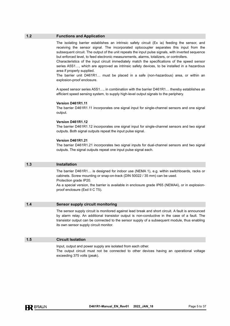
1.2 Functions and Application
The isolating barrier establishes an intrinsic safety circuit (Ex ia) feeding the sensor, and
receiving the sensor signal. The incorporated optocoupler separates this input from the
subsequent circuit. The output of the unit repeats the input pulse signals, with inverted sequence
but enforced level, to feed electronic measurements, alarms, totalizers, or controllers.
Characteristics of the input circuit immediately match the specifications of the speed sensor
series A5S1…, which are approved as intrinsic safety devices, to be installed in a hazardous
area if properly supplied.
The barrier unit D461R1… must be placed in a safe (non-hazardous) area, or within an
explosion-proof enclosure.
A speed sensor series A5S1…, in combination with the barrier D461R1… thereby establishes an
efficient speed sensing system, to supply high-level output signals to the periphery.
Version D461R1.11
The barrier D461R1.11 incorporates one signal input for single-channel sensors and one signal
output.
Version D461R1.12
The barrier D461R1.12 incorporates one signal input for single-channel sensors and two signal
outputs. Both signal outputs repeat the input pulse signal.
Version D461R1.21
The barrier D461R1.21 incorporates two signal inputs for dual-channel sensors and two signal
outputs. The signal outputs repeat one input pulse signal each.
1.3 Installation
The barrier D461R1… is designed for indoor use (NEMA 1), e.g. within switchboards, racks or
cabinets. Screw mounting or snap-on-track (DIN 50022 / 35 mm) can be used.
Protection grade IP20.
As a special version, the barrier is available in enclosure grade IP65 (NEMA4), or in explosion-
proof enclosure (Exd II C T5).
1.4 Sensor supply circuit monitoring
The sensor supply circuit is monitored against lead break and short circuit. A fault is announced
by alarm relay. An additional transistor output is non-conductive in the case of a fault. The
transistor output can be connected to the sensor supply of a subsequent module, thus enabling
its own sensor supply circuit monitor.
1.5 Circuit Isolation
Input, output and power supply are isolated from each other.
The output circuit must not be connected to other devices having an operational voltage
exceeding 375 volts (peak).
D461R1-Manual_EN_Rev01 2022_JAN_18 Page 6 to 37
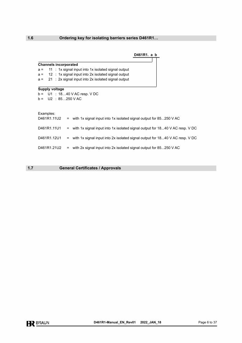
1.6 Ordering key for isolating barriers series D461R1…
D461R1. a b
Channels incorporated
a = 11 : 1x signal input into 1x isolated signal output
a = 12 : 1x signal input into 2x isolated signal output
a = 21 : 2x signal input into 2x isolated signal output
Supply voltage
b = U1 : 18…40 V AC resp. V DC
b = U2 : 85…250 V AC
Examples:
D461R1.11U2 = with 1x signal input into 1x isolated signal output for 85...250 V AC
D461R1.11U1 = with 1x signal input into 1x isolated signal output for 18...40 V AC resp. V DC
D461R1.12U1 = with 1x signal input into 2x isolated signal output for 18...40 V AC resp. V DC
D461R1.21U2 = with 2x signal input into 2x isolated signal output for 85...250 V AC
1.7 General Certificates / Approvals

D461R1-Manual_EN_Rev01 2022_JAN_18 Page 7 to 37
1.7.1 EU Declaration of Conformity
EU-Konformitätserklärung EU Declaration of Conformity
BRAUN GmbH Industrie-Elektronik, Esslinger Str. 26, 71334 Waiblingen, Germany erklärt in alleiniger Verantwortung, declares in its sole responsibility,
dass das Produkt: Trennstufe that the product: Isolating Barrier
Typ(en), types: D461R1…
den genannten Europäischen Richtlinien und harmonisierten Normen entspricht, is in conformity with the listed European Directives and harmonized standards.
EU-Richtlinie(n) / EU-Directive(s) Norm(en), Standard(s)
2014/34/EU ATEX-Produktrichtlinie 2014/34/EU ATEX Product Directive
EN 60079-0:2013+A11:2013 EN 60079-11:2012
Kennzeichnung, marking: II (1) G [Ex ia Ga] IIC 0123
EU-Baumusterprüfbescheinigung Nr.: EU Type Examination Certificate No: Aussteller, notified Body: Benannte Stelle Nr., notified Body No:
CML 15ATEX2128X Certification Management Limited B.V. (CML) Hoogoorddreef 15 Amsterdam, 1101 BA The Netherlands 2776
EU-Richtlinie(n) / EU-Directive(s) Norm(en), Standard(s)
2014/30/EU EMV-Richtlinie 2014/30/EU EMC Directive 2014/35/EU Niederspannungsrichtlinie 2014/35/EU Low Voltage Directive (LVD) 2011/65/EU RoHS-Richtlinie 2011/65/EU RoHS Directive
EN 61326-1:2013 EN IEC 61326-3-2:2018 EN 61010-1:2010+A1:2019 EN IEC 63000:2018
Diese Erklärung gilt für alle Produkte, die mit Typenschildern der oben genannten Typen versehen sind. Zusatzbezeichnungen an Stelle von ... stehen für die spezifische Ausführung. This declaration is valid for all products, which are provided with type labels of the types mentioned above. Suffixes instead of ... are dummy variables for the specific model.
Unbedingte Beachtung aller Punkte der mitgelieferten Betriebsanleitung ist hierbei Voraussetzung. Strict observance of the operation manual is an indispensable precondition, hereto.
Unterzeichnet für und im Namen der BRAUN GmbH / Signed for and on behalf of BRAUN GmbH
Waiblingen, 19-JAN-2021
_____________________________ _____________________________
Ort und Datum Albrecht Braun Place and date Geschäftsführer Managing Director
Figure 1: EU Declaration of Conformity

D461R1-Manual_EN_Rev01 2022_JAN_18 Page 8 to 37
2 Hazardous protection
The safety requirements as determined by EN 1127-1, as well as the corresponding national
regulations, are to be complied with regarding primary explosion protection, i.e. measures which
prevent or restrict the formation of a hazardous explosive atmosphere.
In the case of secondary hazardous protection, i.e. measures that prevent the ignition of an
explosive atmosphere surrounding electrical equipment, the series of standards applicable to
EN 60079 and the relevant national regulations must be observed.
2.1 Relevant technical Data for Hazardous Area
Approved maximum values:
Uo = 8.7 V
Io = 64 mA
Po = 384 mW
Lo = 7.9 mH (IIC)
= 38 mH (IIB)
Co = 5.9 µF (IIC)
= 50 µF (IIB)
2.2 ATEX Certification for Intrinsic Safety of the Input Circuit
II (1) G [Ex ia Ga] IIC
Marking of notified Body: CE0123
EU Type Examination Certificate: CML 15ATEX2128X
2.3 Explosive relevant Certificates / Approvals
2.3.1 ATEX
The isolating barrier series D461R1… is certified according to ATEX EC-Type Examination
Certificate No. CML 15ATEX2128X and is compliant according to ATEX Product Directive
2014/34/EU. Marking see ATEX EU Type Examination Certificate chapter 2.3.7.
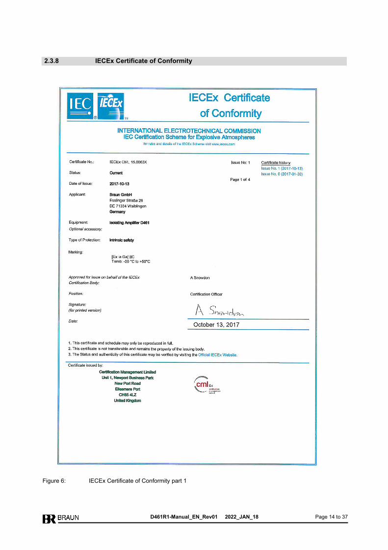
2.3.2 IECEx
The isolating barrier series D461R1… is certified according to IECEx Certificate of Conformity
No. CML 15.0063X. Marking see IECEx Certificate of Conformity chapter 2.3.8.
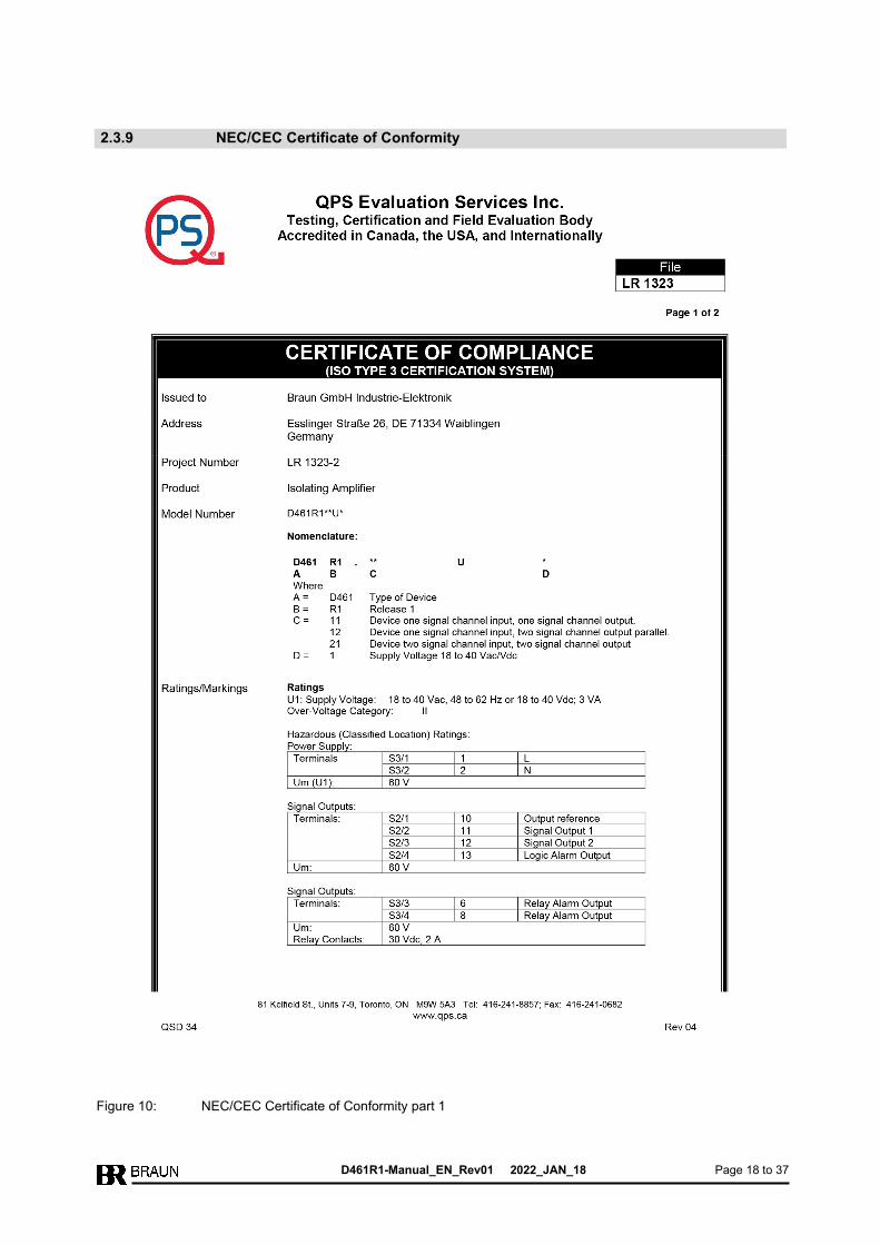
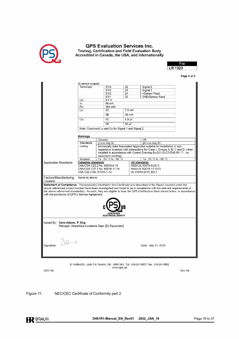
2.3.3 USA (NEC) and Canada (CEC)
The isolating barrier series D461R1… is certified for the USA and Canada according to QPS
Certificate of Conformity No. LR 1323-2. Marking see NEC/CEC Certificate of Conformity
chapter 2.3.9.
2.3.4 EAC Ex
The isolating barrier series D461R1… is approved for EAC (Russia, Kazakhstan and Belarus
Customs Union) according to TR-Certificate No. RU С-DE.ОБ01.B.00175 and TR CU 012/2011.
Marking see EAC Ex TR CU Certificate chapter 2.3.10.
D461R1-Manual_EN_Rev01 2022_JAN_18 Page 9 to 37
2.3.5 UKEX
The isolating barrier series D461R1… is certified for UKEX according to UKEX UK Type
Examination Certificate No. CML 21UKEX2052X and are compliant according to UK statutory
requirements SI 2016 No. 1107. Marking see UKEX UK Type Examination Certificate chapter
2.3.11.
2.3.6 KCs
The isolating barrier series D461R1… is certified for South Korea according to KCs certificate
No. 21-AV4BO-0260X by KOSHA. Marking see KCs certificate chapter 2.3.12.

D461R1-Manual_EN_Rev01 2022_JAN_18 Page 10 to 37
2.3.7 ATEX EU Type Examination Certificate
Figure 2: ATEX EU Type Examination Certificate part 1

D461R1-Manual_EN_Rev01 2022_JAN_18 Page 11 to 37
Figure 3: ATEX EU Type Examination Certificate part 2

D461R1-Manual_EN_Rev01 2022_JAN_18 Page 12 to 37
Figure 4: ATEX EU Type Examination Certificate part 3

D461R1-Manual_EN_Rev01 2022_JAN_18 Page 13 to 37
Figure 5: ATEX EU Type Examination Certificate part 4
D461R1-Manual_EN_Rev01 2022_JAN_18 Page 14 to 37
2.3.8 IECEx Certificate of Conformity
Figure 6: IECEx Certificate of Conformity part 1

D461R1-Manual_EN_Rev01 2022_JAN_18 Page 15 to 37
Figure 7: IECEx Certificate of Conformity part 2

D461R1-Manual_EN_Rev01 2022_JAN_18 Page 16 to 37
Figure 8: IECEx Certificate of Conformity part 3

D461R1-Manual_EN_Rev01 2022_JAN_18 Page 17 to 37
Figure 9: IECEx Certificate of Conformity part 4
D461R1-Manual_EN_Rev01 2022_JAN_18 Page 18 to 37
2.3.9 NEC/CEC Certificate of Conformity
Figure 10: NEC/CEC Certificate of Conformity part 1
D461R1-Manual_EN_Rev01 2022_JAN_18 Page 19 to 37
Figure 11: NEC/CEC Certificate of Conformity part 2

D461R1-Manual_EN_Rev01 2022_JAN_18 Page 20 to 37
2.3.10 EAC Ex TR CU Certificate
Figure 12: EAC Ex TR CU Certificate part 1

D461R1-Manual_EN_Rev01 2022_JAN_18 Page 21 to 37
Figure 13: EAC Ex TR CU Certificate part 2

D461R1-Manual_EN_Rev01 2022_JAN_18 Page 22 to 37
Figure 14: EAC Ex TR CU Certificate part 3

D461R1-Manual_EN_Rev01 2022_JAN_18 Page 23 to 37
Figure 15: EAC Ex TR CU Certificate part 4

D461R1-Manual_EN_Rev01 2022_JAN_18 Page 24 to 37
2.3.11 UKEX UK Type Examination Certificate
Figure 16: UKEX UK Type Examination Certificate part 1
D461R1-Manual_EN_Rev01 2022_JAN_18 Page 25 to 37
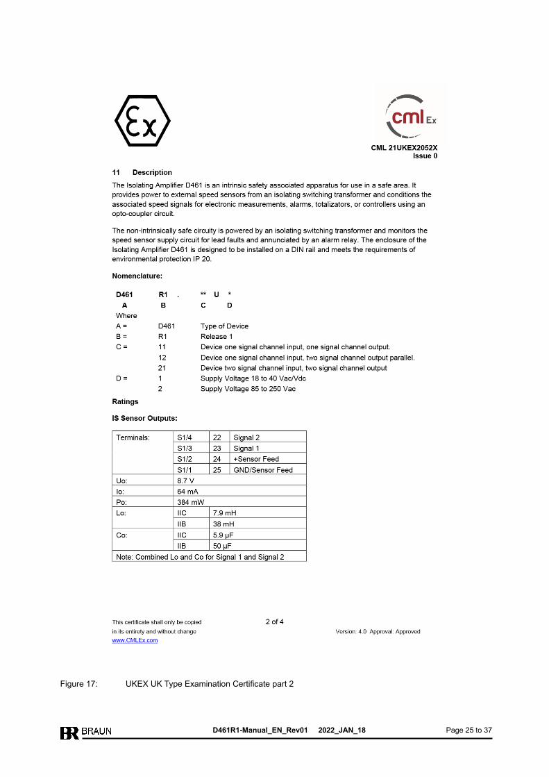
Figure 17: UKEX UK Type Examination Certificate part 2

D461R1-Manual_EN_Rev01 2022_JAN_18 Page 26 to 37
Figure 18: UKEX UK Type Examination Certificate part 3
D461R1-Manual_EN_Rev01 2022_JAN_18 Page 27 to 37
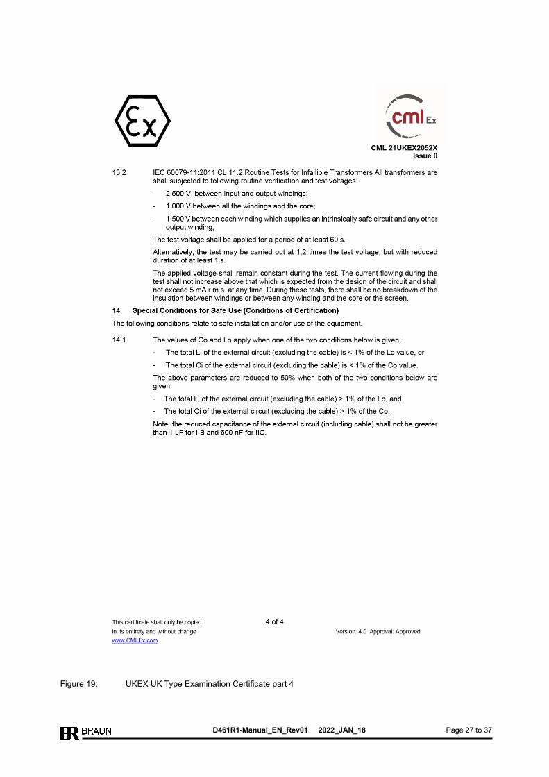
Figure 19: UKEX UK Type Examination Certificate part 4

D461R1-Manual_EN_Rev01 2022_JAN_18 Page 28 to 37
2.3.12 KCs Certificate
Figure 20: KCs Certificate part 1

D461R1-Manual_EN_Rev01 2022_JAN_18 Page 29 to 37
Figure 21: KCs Certificate part 2

D461R1-Manual_EN_Rev01 2022_JAN_18 Page 30 to 37
3 Function Diagram and Connections
3.1 Function Diagram and Connection D461R1.11
Figure 22: Function Diagram and Connection D461R1.11

D461R1-Manual_EN_Rev01 2022_JAN_18 Page 31 to 37
3.2 Function Diagram and Connection D461R1.12
Figure 23: Function Diagram and Connection D461R1.12

D461R1-Manual_EN_Rev01 2022_JAN_18 Page 32 to 37
3.3 Function Diagram and Connection D461R1.21
Figure 24: Function Diagram and Connection D461R1.21

D461R1-Manual_EN_Rev01 2022_JAN_18 Page 33 to 37
4 Technical Specifications
4.1 Technical Data of Inputs (intrinsic safe)
Response level 4 V, Input impedance approx. 47 k.
Sensor supply (operational value) 8 volts.
Approved maximum values: Uo = 8.7 V
Io = 64 mA
Po = 384 mW
Lo = 7.9 mH (IIC)
= 38 mH (IIB)
Co = 5.9 µF (IIC)
= 50 µF (IIB)
Versions D461R1.11 and D461R1.12
The sensor has to be connected to the signal input by 3 leads shielded cable. Recommended
wire cross section LiYCY 3x0.5 or larger.
Version D461R1.21
The sensor has to be connected to the signal input by 4 leads shielded cable. Recommended
wire cross section LiYCY 4x0.5 or larger.
4.2 Technical Data of Outputs
Outputs are short-circuit-proof and free-floating versus power supply and input.
Active pulses by push-pull transistor output stage, sequence inverting the input signal.
Output level with maximum load towards 0 V: High-Level approx. 18 V
Low-Level 0 V
Output level with maximum load towards 24 V: High-Level approx. 20 V
Low-Level approx. 2 V
Version D461R1.11 incorporates one signal output, versions D461R1.12 and D461R1.21
incorporate two signal outputs each.
4.3 Technical Data of Power Supply
D461R1.xxU1: 18...40 V AC resp. V DC, power requirements approx. 5 VA.
D461R1.xxU2: 85...250 V AC, power requirements approx. 5 VA.
4.4 Environmental conditions
Ambient temperature in operation: -20 °C...+50 °C
Ambient temperature in storage: -20 °C...+85 °C
Relative humidity: < 95%, non-condensing
To be installed in dry cabinets in air-conditioned rooms
Up to 2000 meters above sea level
4.5 Protection Grade
Protection Grade: IP20
As a special version, the barrier is available in enclosure grade IP65
(NEMA4), or in explosion-proof enclosure (Exd II C T5).

D461R1-Manual_EN_Rev01 2022_JAN_18 Page 34 to 37
4.6 Connectors
Connectors with Pull Spring Terminals
4.7 Conformity to Standards
Directives Standards
2014/34/EU ATEX Product Directive EN 60079-0, EN 60079-11
2014/30/EU EMC Directive EN 61326-1, EN IEC 61326-3-2
2014/35/EU Low Voltage Directive (LVD) EN 61010-1
2011/65/EU RoHS Directive EN IEC 63000
UK statutory requirements Standards
SI 2016 No. 1107 (amended by SI 2019 No. 696) BS EN 60079-0
BS EN 60079-11
D461R1-Manual_EN_Rev01 2022_JAN_18 Page 35 to 37
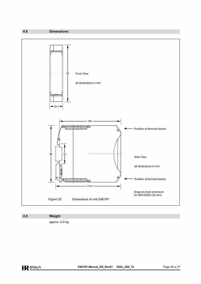
4.8 Dimensions
4.9 Weight
approx. 0.4 kg.
Front View all dimensions in mm
99
22,5
Snap-on-track enclosure for DIN 50022 (35 mm)
99
114,5
Position of terminal blocks
Side View all dimensions in mm
Figure 25: Dimensions of unit D461R1
108
35
Position of terminal blocks

D461R1-Manual_EN_Rev01 2022_JAN_18 Page 36 to 37
5 Safety Notes for Installation and Operation
5.1 Safety Notes for Installation
The isolating barriers series D461R1… has been designed and tested according to the
standards EN 61010-1 (VDE 0411-1) and have left the factory in perfect safety condition. To
maintain this condition and to ensure safe operation, the user must observe the notes and wiring
diagrams contained in this operating manual.
Installation and maintenance work must be done only by adequately qualified personnel and
only when the power supply is switched off.
5.1.1 General Instructions
The isolating barriers series D461R1… shall be installed in the non-hazardous area, resp.
protected by an explosion-proof enclosure.
5.1.2 EMI
The isolating barriers series D461R1… complies with all relevant regulations, as determined by
the Policy of the European Committee for Electrotechnical Standardization (CENELEC), for the
Electromagnetic Compatibility (2014/30/EU). Testing and inspection have been performed
according to Standards EN 61326-1 and EN IEC 61326-3-2. Thereby, the product meets all
requirements to be marked by the CE sign.
Strict observance of these instructions during installation and use is an indispensable pre-
condition hereto.
5.2 Safety Notes for Operation
5.2.1 Safety Notes on Commissioning
Commissioning must be carried out by sufficiently competent and qualified personnel.
During commissioning of the entire machine, the commissioning technician must ensure that the
measuring chains function properly.
D461R1-Manual_EN_Rev01 2022_JAN_18 Page 37 to 37
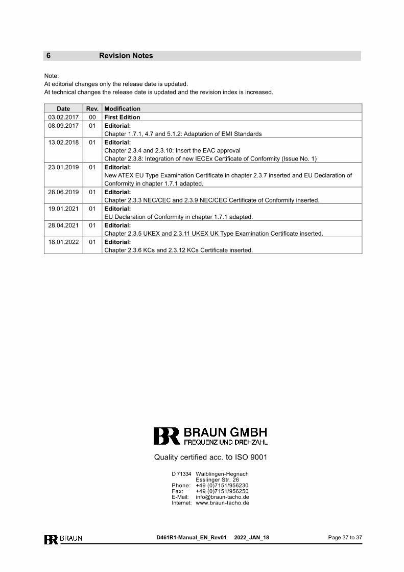
6 Revision Notes
Note:
At editorial changes only the release date is updated.
At technical changes the release date is updated and the revision index is increased.
Date Rev. Modification
03.02.2017 00 First Edition
08.09.2017 01 Editorial:
Chapter 1.7.1, 4.7 and 5.1.2: Adaptation of EMI Standards
13.02.2018 01 Editorial:
Chapter 2.3.4 and 2.3.10: Insert the EAC approval
Chapter 2.3.8: Integration of new IECEx Certificate of Conformity (Issue No. 1)
23.01.2019 01 Editorial:
New ATEX EU Type Examination Certificate in chapter 2.3.7 inserted and EU Declaration of
Conformity in chapter 1.7.1 adapted.
28.06.2019 01 Editorial:
Chapter 2.3.3 NEC/CEC and 2.3.9 NEC/CEC Certificate of Conformity inserted.
19.01.2021 01 Editorial:
EU Declaration of Conformity in chapter 1.7.1 adapted.
28.04.2021 01 Editorial:
Chapter 2.3.5 UKEX and 2.3.11 UKEX UK Type Examination Certificate inserted.
18.01.2022 01 Editorial:
Chapter 2.3.6 KCs and 2.3.12 KCs Certificate inserted.
D 71334 Waiblingen-Hegnach Esslinger Str. 26 Phone: +49 (0)7151/956230 Fax: +49 (0)7151/956250 E-Mail: [email protected] Internet: www.braun-tacho.de
Quality certified acc. to ISO 9001