Manual: GMH100 OM PIONEER EN
18
G G
Transcript of Manual: GMH100 OM PIONEER EN

GIVMi-H1100
GM-HiS

important
The serial number of this amplifier is on the bottom. For your own security and convenience, write it down on the enclosed warranty card. Keep the card handy for future reference.
» WARNING Connection
| »® Remove the negative lead of the battery, otherwise there may be a short circuit, or the lead may be | ! damaged.
/ * Use the supplied battery lead, as other leads may cause a fire. | ¢ If the fuse in the battery iead needs to be replaced, use a fuse with the same rating. Do not use a piece of
| wire instead of the fuse, as it may cause a fire.
installation | « If the amplifier is installed in the passenger compartment, fix it securely, otherwise it may break free while
the car is moving, and cause an injury or an accident. | ® Do not install the amplifier anywhere that can get wet, otherwise it may give an electric shock if touched.
| Use e When the amplifier is in use, its temperature reaches 176 degrees Fahrenheit or higher. Do not touch it,
otherwise you may be burned. ;
6

Controls and their Use
Power
—Adjustment screwdriver {supplied}
¥. Bass Freq. V. Bass Level
AOH2 @ 120Hz (eX
ods @ 1208
RCA Level
fo N 2v @ 200mv
@ Power indicator The power indicator lights when the power is switched on.
@ Variable Bass Frequency Control Adjusting the variable bass frequency control § the boostable bass frequency of the amplifier. You can select a frequency in the range 40 to 120 Hz. Adjust the boostable bass frequency ta suit the speakers or the music.
® Variable Bass Level Control Adjusting the variable bass level control changes the | boostable bass frequency set by control @ « ff you do not want to boost the bass. turn the control fully counterclockwise
to 0 dB.
@ RCA Input Level Control lf the output is low even when the volume of the car stereo is turned up, turn this control clockwise. If there is distortion when the volume of the car stereo is turned up, turn this control counterclockwise. + Adjust controls @. @, and @ with the supplied adjustment sc river
eep the screwdriver in case you need to readjust the controls later. 2 in low-trequeri unds may be noticeable whan the 40-to
120-Hz frequency level is adjusted if the program components in the 40-to-120-Hz range or if smalldis used,

BFC (Beat Frequency Control) switch If beating is heard when listening to AM stations on your car radio, change the position of the BFC switch on the bottom of the amplifier with a smiail flat-bladed screwdriver.
BFC switch

Connecting the Units
Connect the components as shown in the diagram « Before finalizing installation, turn everything on, and make sura
everything works correctly and that no noise is getting into the system
« When routip and cords, secure ther and dhesiv Also, to the insulation on the leads adhesive tape wh
p all wiring away from hot sur
vwith cable retainers emt any damage to
® [tis recoran have the ratings shown below, or higher. If a speaker has a rating below that recommended, it may be damaged when the volume is turned up. The speaker impedance must be 2 to 8 ohms.
Teer anty tT | : Speaker ratings Pl
Mode GMHi00 | GM.H50 - - : Maximum 100 W j 50 W |
hwo-cheane! Norminat im 5OW 25W
2 Maximum 1 320 W 160 W jp oe channel Nominal 160. W 80 W
In the case of a fullrange speaker, use one whose maxinum rating is
higher than the maximum rating shown. In the case of a sub-woofee, use one whose nominal rating is higher than the nominal rating shawn,
Never connect a speaker lead to ground or to other speaker grounds.
The protection circuitry will operate instantaneousty, turning off the amplifier.
To prevent noise problems, keep the power leads to the amplifier
away from the signal cords (RCA cords) and speaker leads. Also, keep the power leads away from any antenna cords. Amplifier ground | 5 (black) should be connected to a solid
metal part of the vehicle body. if using multiple amplifiers, connect all amplifier ground leads to the same point 19 prevent noise problerns. To get good contact when grounding, you may have to sand
away the paint to expose ihe metal underneath To operate the amplifier and car stereo properly, connect the
battery lead and the accessory power lead (red) correctly, If the leads are not connected correctly or are not connected at all, the amplifier and car stereo will not work.
For detailed information on connections between different units and the amplifier, see ihe owner's manuals for the units, and foilow their recommendations precisely,
as

Connecting the battery lead (red) Route the battery lead (red) from the engine compartment to the passenger compartment to connect it to the amplifier. To prevent a short circuit, do not connect the positive (+) lead of the battery until the other ieads have been connected.
Passenger compartment « | » Engine companment EEA ZL
C4 7i* { }
Battery todd fred) of aN
{Insert the grom
| Fuse
at into the hole.
Connect the leads, finishing with the positive (+) lead, which goes directly to the positive (+) battery terminal.
ag
ey
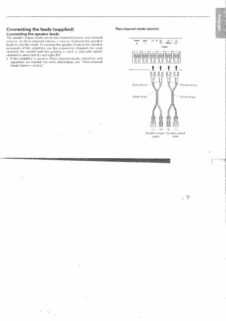
Connecting the leads (supplied) Two-channel mode (stereo) Connecting the speaker leads The speaker output mode can be two-channel {stereo}, one-channel {mano}, or three-channel istereo + mono). Connect the speaker Power GND © A 8 fom Q leads to suit the mode. To connect the speaker leads to the speaker + 7 aia) terminals of the amplifier, see the connection diagram for each channel. Be careful with the polarity (+ and ~), and with which channel is which (left {L] and right [R}) « if the amplifier is used in three-channel mode, inductors and
capacitors are needed. For more information, see “Three-channet mode (stereo + mono)”
Sutput
Gray sleeve. Green sleeve
Black stripe Green stripe

One-channel mode (mono)
Power BND © R 8 WSet ee —Mene— Gutpat
” Black sleeve
Three-channel mode (stereo + mono)
The power amplifier is basically a two-channelone-channet bridgeable amplifier, but three channels can be catered for by cambining the stereo and mone modes using inductors and capacitors. Some typical examples are given below. * As making this connection does require a knowledge of electroni
done by your dealer or by someone specializing in such
get it
Example 1 Three-channel, two-way system
@ t Monv:
Outpt
Right Loft mid4tweeter mid-tweeter

Example 2 Three-channel, three-way system
Mono-woofer’ subwoofer
Power GND © R g @t £ Mone
Gutput
d Right Right Left Left tweeter!
tweeter! mid-range) mid-range’ — mid-high mid-high mid-bass — mid-bass unit
unit unit unit
The inductor (L1 or L2 in the diagram} acts as a low-pass fitter. The capacitor (C1 or C2 in the diagram) acts as a high-pass filter in three-channel mode, connect the inductor (L} to the woofer / subwoofer, and the capacitor (C) to the mid-tweeter / tweeter / mid-high unit. The filters {low-pass and high-pass) must be used in three
channel mode, otherwise the total load will be 202 ar fess, and the amplifier may fail, even if the speaker impedance is 4Q. if the inductors and. capacitors are connected to the speaker leads, secure or solder thern. so they cannot, be pulled loose. Tape the joints to prevent short circuits.

Setting the filter constant Component Guide 1 Low-pass filter (for subwoofer/woofer): 6 dB/octave i ‘Speaker toad | 20 | 40 i BO jee . ; i : ide = i | fetHey | Lime | CED | Lerma Cw | Lime) | C mr G91 ‘as t : + y aq | 50 64 | 1600 | 127 | 800 | 285 | 400 | i | ; 80 | 40 | 100 | 80 | 500 | 16 | 250 | | eee at,
nn a) 560 | 51 300 10 | 160 o—---- | Ste ease eae ; 2000 16 | 400 | 32 | 200 | 64 | 100
i @ High-pass filter (for mid-tweeter/mid-high-tweeter}: | 3200 10 | 502.0 6 | 4 1 62 ] i i
6 dB/octave | S00 064 | 160 | 13 | 90 26 | 40 i ! i C1 i | 800 0.4 100 og | 0 6 25 o—~ aoe | Bae S ; 1250 | 0.25 i 64 05 30 1.0 16
i | | ng | 2600 0% | 40 03 | 20 | 064 10 Q-—-— > | 3200 Or | 25 02 | 25) of | 62] fe | | | a | 5000 | 0.06 | 16 013; 8 | o26 | 4 @ Band-pass filter (combination of low-pass filter and high-pass j so00 | «(o.04 | 10 0.08 | 5 | o6@ | 25 | filter for mid-bass/mid): 6 dB/octave
i ] ‘i | 10000 «| «0.03 a | | i 006 | 4 | O18 | 2 H i : ere i ot =o m
L2 2 O— 131
+ A multi-channel system can be set up using a combination of filters ‘1, -2., and ‘3°. The inductance (L) and capacitance (C) that determine the frequency (fc) applicable to the system should be chosen according to the above table .
* Use the capacitors specified! Non-polarize ‘over £25V should be used for C1 and Ci
EQ
10
ao) 5

Connection procedure for speaker, battery, 3. Connect the battery lead to the battery lead terminal, reinserting and ground leads and tightening the screw.
1. Pass the leads through the band for preventing short circuits. « This band must be used.
Bauery lead
4. Connect the ground lead ta the ground lead terminal, tightening | the 2. Loosen the screws of the terminals on the rear panel, and remove
the screw of the battery leacl terminal.
terminal scraw Terminal screw i
|
i
Ground lead |
i Remove only the screw of the battery lead terminal. (Loosen all the other screws.) | Ground lead terminal

5, Arrange the speaker leads to suit the output mode to be used, connecting them to the speaker output terminals, and tightening the screws
Terminal screw
Speaker lead terminal
HRN
Ne Speakér output terminal
Short-circuit prevention band
/
12
aan

Connect all the other leads, and finally connect this terminal to the positive (4) terniinal of the battery,
Connect to metal body or chassis.
ignition switch (12 V DC) ON/ORR |
_ <j] _-Green stripes
<I | Red Left-hand speaker
Car stereo with P = |
RCA pin jacks
™ Black stripes
Connecting leads with RCA Right-hand speaker pin plugs (sold separately}
Battery lead fuse.
Red = White
Fuse holder
Blue ., Black
\ jactric terminal controlled by Red/Black the male terminal of this lead to the blue lead of the reo (system control terminalj. The female terminal can cted to the auto-antenna relay control terminal. Fuse holder ,
Note 1: The speaker leads are co whether the output mod ane-channel. For details, s diagram shows how to wire mode.
nnected differently depending on is three-channel, two-channel, or
8 and 9. This connection e amplifier for two-channel
13
noeeastanmeel

Installation
2 Install the amplifier where it will not get in the way of driving, and will not be a danger to passengers during an emergency stop:
e ifthe amplifier is instailed in the passenger compartment, fix it securely, otherwise it may break free while the car is moving, and cause an injury or an accident
e Do not install the amplifier anywhere that can get wet, otherwise it may give an electric shock if touched.
© To prevent a short circuit, disconnect the negative battery lead before beginning installation. After installation has been completed and checked, reinstall any components that were moved or removed, then reconnect the lead to the negative battery terminal.
¢ Before drilling any mounting holes, check behind where you want 1o make the hole to make sure you do not drill into anything, such
the gas line, brake lines, electrical wiring, ete. If installed under a front seat, make sure the amplifier does not obstruct seat movement. Route ali ileads and cords carefully so the sliding seat mechanism does not pinch them and cause a short circuit,
* Do not install the amplifier under the carpet or a floor mat, as this will impede air circulation, causing the amplifier to overheat and possibly fail
¢ Do not install the arnplifier near the heater outiet, otherwise it may overheat and fail
e Use only the parts supplied, and install the amplifier securely. If parts other than those supplied (specified) are used, they may come loose or cause damage to internal parts of the amplifier.
e Gonsull your dealer before making any holes in the car.
14
» If mounting the amplifier vertically, buy some 5-mrm-diameter
screws and nuts, and use them to secure the amplifier firmly, so that it cannot be dislodged by the vibration of the car.
+ There are 4-mm-diameter screw holes on the right and left at the rear of the amplifier, These are used to fit an optional amplifier installation end cap. Do not use them for anything else
Screw holes (4-mrm-diametert
for end ¢

Example of Installation Positions . Put the amplifier where it is ta be installed, insert the supplied selfapping acrews (6 « 65 mim} inta the ew holes, and push on them with a screwdriver so they make marks where the installation holes are to go. 2. Drill 2-mm-diameter holes
amplifier, either on the fl at the points marked, and install the O08 Mat or directly an the chassis.
Under a front saat 5 = 65 mm}
Inside the trunk {Drill a hole into the pas Sssenger compartment, and pass the leads. through
Grill 3-mm diameter holes
16
semen

Care and Maintenance Specifications
[ |
When replacing the fuse, replace it with one with the correct rating. If the correct fuse is not used, the amplifier may be damaged ar there may be a fire. Do not use the amplifier at high volume for a long time with the engine stopped or idling. It may make the battery go flat, making it difficult to start your engine. The protection circuitry will operate instantaneously if a mal- function occ connect the power to the car 5
rs, turning off the amplifier. ff this happens. dis- 2reo system, check the wiring for
the cause of the problern, and, if found, correct it before using the stereo system again. Do not turn the volume up so high that you cannot hear police car, ambulance, or fire engine sirens.
In Case of Problems lf the amplifier will nat operate properly, contact your dealer or nearest authorized Pioneer service station
POWET SOUFCE ooo. 14.4 V DC M08 - 18.6 ¥ allowable) Grounding system ..... Wide oeie Ades Negative type Current consumption (GM-H100) wanes Hts 13 A (at continuous pawer, 4£2) ({GM-H50} .. ota 6.5 A fat continuous power, 40)
Fuse ({GM-H100} cern BO A {GM-H50) SA
Dimensions {GM-H 100) once tereteseeseessteeeeeseeen 264 (VW) « 5S. {H) « 260 (D} morn
140 - 3/8 (W) x 2. 1/4 1H) 10-14 (D) in] (GM-H50) base +264 (W) « 52 (H) = 980 (D) mm
110 - 3/8 (WW) « 24H} 7-1/8 (D) in] Weight {GM-H100) . ds for wiring not included) (GM-H50} {s for wiring not included)
Maximum power output ({GM-H100) decetenseceasies seen TOO Ws 2/820 Woe 1 EIA) {GM-H50) pikes te cessiche nants 50 W 2/160 Wx 1 (ELAS)
Continuous power output (GM-H100} ..........50 W « 2/160 W = 1 (at 42, 20 - 20,000 Hz, 0.05% THD)
80 W » 2 (at 242, 20 - 20,000 Hz, 0.05% THD} (GM-H50}.... 25 Wx 2/80 Wee Vat 4: ‘0 - 20,000 Hz, 0.05% THD}
40 W 2 {at 202, 20 - 20,000 Hz, 0.05% THD) aeisnitan sh sess OQ (2 » 8Q allowable)
» 10 - 60,000 Hz (+0 dB, -1 dB) 100 dB {IHF « A network)
Load impedance .......... Frequency response .. Signal-to-noise ratio. Distortion (GM-H100) . {GM-H50}
Separation Input level
corer O.003% (at 20 W, 1 kHz) 0.003% (at 10 W, 1 kHz)
-65 dB (1 kHz) 0.2-2V /BkKQ
These specifications were determined and are presented in accordance with specification standards established by the Ad Hoc Cornmittee of Car Stereo Manutacturers.
Note: Specifications and the design are subject to possible modification without notice due to improvements,

AVERTISSEMENT ah Bat. *sd
Connexion * Déposer te fil négatif de la batterie, sinon un court-circuit risque de se produire, ou bien le fil risque de
s'endommiager. « Utiliser le fil de batterie fourni, car les autres fils risquent de causer un incendie. * Si le fusible du fil de la batterie doit étre rempiacé, utiliser un fusible avec la méme valeur nominale. Ne
pas utikser un fil au lieu d’un fusible, car il peut causer un incendie.
Installation ¢ Si l'amplificateur est installé dans le compartiment des passagers, le fixer fermement, sinon il risque de se
deétacher pendant que la voiture se déplace, et causer une blessure ou un accident. * Ne pas installer !‘amplificateur 1a ou il peut étre mouillé, sinon il risque de causer une secousse électrique
s‘il est touché.
Usage ° Quand l’amplificateur est en fonctionnement, sa température atteint 176 degrés ou davantage. Ne pas le
toucher, sinon on risque de se briler.