Manual Geho
242
VENDOR DOCUMENT IDENTIFICATION Sales order no. 201253 Pump type TZPM 1200 Document title Revision 0 EPSN document code 201253-IOMT CLIENT DOCUMENT IDENTIFICATION P.O. No. 500P-MR-315-01 Purchaser order Title Esperanza Project Esperanza Project No. C-550 Client Type code X009 Client document code X009 Client Esperanza Pumptype TZPM 1200 SUBMISSION STATUS 0 02-feb-09 for approval MM Rev. Date Description of issue Sign. I.O.M. Instructions Typical
-
Upload
herman-fernandez-chamorro -
Category
Documents
-
view
1.199 -
download
220
description
manual de operación bomba
Transcript of Manual Geho

VENDOR DOCUMENT IDENTIFICATIONSales order no. 201253
Pump type TZPM 1200
Document title
Revision 0
EPSN document code 201253-IOMT
CLIENT DOCUMENT IDENTIFICATIONP.O. No. 500P-MR-315-01
Purchaser order Title Esperanza
Project Esperanza
Project No. C-550Client Type code X009Client document code X009Client Esperanza
Pumptype TZPM 1200
SUBMISSION STATUS
0 02-feb-09 for approval MM
Rev. Date Description of issue Sign.
I.O.M. Instructions Typical
Weir Minerals Netherlands
P.O. Box 249, 5900 AE Venlo, the Netherlands Egtenrayseweg 9, NL-5928 PH Venlo
4495 Registration No.: 12032525
Tel: +31(0)77 3895200 Fax: +31(0)77 3824844 Email: [email protected] WWW: http://www.weirminerals.com
Copyright © Weir Minerals Netherlands b.v. 2008. Weir Minerals Netherlands b.v. is the owner of the copyright subsisting in the instructions and drawings stored in this manual. All material of this manual are protected by the Dutch Copyright Law, international treaty provisions and applicable laws in the country in which it is being used. The material must not be used, reproduced or copied in whole or in part, in any form or by any means, nor may the information therein contained, which is confidential to Weir Minerals Netherlands b.v be disclosed to any person without the prior written permission of Weir Minerals Netherlands b.v. Furthermore you may not rent, lease, sublicense or lend the manual and its contents. The manual has been delivered and received on the express condition that it may be used only for the specific purpose for which it has been provided and may not be used in any way which may injure or cause loss directly or indirectly to Weir Minerals Netherlands b.v. or any related corporation. Disclaimer. Except to the extent legislation expressly prohibits the exclusion of provisions as to warranties, Weir Minerals Netherlands b.v. disclaims all warranties as to the instructions and drawings, whether express or implied, including without limitation any implied warranties of merchantability, fitness for a particular purpose, compatibility with any particular system, or data integrity and the user assumes all responsibility for the use of the software on its system.
Installation, Operating and Maintenance Manual
WEIR Pump type : TZPM 1200
WEIR Pump number :
WEIR Project name :
WEIR Document number :
Customer P.O. number :
CT253
Text Box
"Typical"


Preface
MUI.814.201189.R01.EN 1.1
Pos: 1.1.1 /GEHO/Heading/H1/#. Preface @ 0\mod_1133187936567_31.doc @ 111
1 Preface Pos: 1.1.2 /GEHO/Preface/General/Diaphragm pumps/Introduction @ 0\mod_1133188276656_31.doc @ 121
This pump is developed by Weir Minerals Netherlands. Pos: 1.1.3 /GEHO/Preface/General/Common intro @ 0\mod_1139913202827_31.doc @ 2530
This manual with its user and safety instructions is an integral part of the pump delivery and must be kept in its neighborhood, accessible for reference at all times.
All persons involved in using and operating this pump and working at this pump must have read and understood this manual and must comply with it at all times. We accept no responsibility for damage or disruption caused by disregard of this manual and its instructions.
Scope of this manual This manual and its user instructions apply to the GEHO PUMPS equipment during: Pos: 1.1.4 /GEHO/Preface/General/Purpose - Final @ 0\mod_1139912839316_31.doc @ 2518
• Transport • Installation • Operation, start and stop procedure • Maintenance
Pos: 1.1.5 /GEHO/Preface/General/Use @ 0\mod_1133427209923_31.doc @ 246
This equipment, supplied by Weir Minerals Netherlands, is only allowed to be used, according to and restricted to the technical data. Before exceeding the technical data, a written permission from Weir Minerals Netherlands is required. Pos: 1.2 /GEHO/Preface/Project/201189/General overview @ 5\mod_1225107795665_0.doc @ 39770
Pos: 1.3 /GEHO/Heading/H2/#.# Revision form @ 0\mod_1133271476093_31.doc @ 213
Preface
1.2 MUI.814.201189.R01.EN
1.1 Revision form Pos: 1.4 /GEHO/Preface/Project/201189/Revision form Final @ 5\mod_1226591321077_31.doc @ 43696
Rev. No. Chapter Description By Checked Date R00.EN Preliminary release
Manual Transport and Installation JOH
R01.EN Final release Installation, Operating and Maintenance Manual
JOH
Pos: 2 /--- Section break - Next page --- @ 0\mod_1133257917306_0.doc @ 151

Contents
MUI.814.201189.R01.EN 2.1
Pos: 3 /GEHO/General/Special formats/Table of contents @ 0\mod_1133257649241_31.doc @ 147
2 Contents
1 Preface ....................................................................................... 1.1
1.1 Revision form...............................................................................................1.2
2 Contents..................................................................................... 2.1
3 SAFETY...................................................................................... 3.1
3.1 Safety symbols ............................................................................................3.1
3.2 Important information.................................................................................3.2
3.3 Intended use ................................................................................................3.3
3.4 General safety instructions........................................................................3.3
3.5 Qualified workers ........................................................................................3.3
3.6 Working on the pump .................................................................................3.3
3.7 Efficient use .................................................................................................3.3
3.8 Safety equipment ........................................................................................3.3 3.8.1 Safety related documentation.................................................................................... 3.3 3.8.2 CE conformity ............................................................................................................ 3.3 3.8.3 Emergency stop button ............................................................................................. 3.4 3.8.4 Safety covers and safety guards............................................................................... 3.4
4 Technical data ........................................................................... 4.1
4.1 Project information......................................................................................4.1
4.2 Customer information.................................................................................4.1
4.3 Manufacturer information...........................................................................4.1
4.4 Technical data..............................................................................................4.2 4.4.1 Operating characteristics........................................................................................... 4.2 4.4.2 Pump and project data .............................................................................................. 4.3 4.5 Tightening torques......................................................................................4.5 4.5.1 General torques......................................................................................................... 4.5 4.5.2 Foundation bolt torques according to DIN 529 ......................................................... 4.5 4.5.3 Special torques.......................................................................................................... 4.5 4.6 Auxiliary connections and lubrication data .............................................4.7
4.7 Drawings + lists + instruments ..................................................................4.8
5 Description ................................................................................ 5.1
5.1 Introduction..................................................................................................5.1
5.2 Working principle ........................................................................................5.2 5.2.1 Suction stroke ............................................................................................................ 5.2 5.2.2 Discharge stroke........................................................................................................ 5.2 5.3 Drive unit ......................................................................................................5.3
Contents
2.2 MUI.814.201189.R01.EN
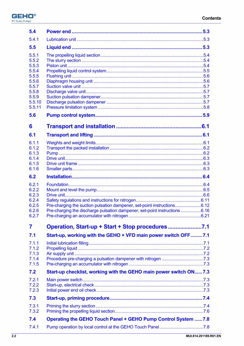
5.4 Power end ....................................................................................................5.3 5.4.1 Lubrication unit ...........................................................................................................5.3 5.5 Liquid end ....................................................................................................5.3 5.5.1 The propelling liquid section.......................................................................................5.4 5.5.2 The slurry section .......................................................................................................5.4 5.5.3 Piston unit ...................................................................................................................5.4 5.5.4 Propelling liquid control system..................................................................................5.5 5.5.5 Flushing unit ...............................................................................................................5.6 5.5.6 Diaphragm housing unit .............................................................................................5.6 5.5.7 Suction valve unit .......................................................................................................5.7 5.5.8 Discharge valve unit ...................................................................................................5.7 5.5.9 Suction pulsation dampener.......................................................................................5.7 5.5.10 Discharge pulsation dampener ..................................................................................5.7 5.5.11 Pressure limitation system .........................................................................................5.8 5.6 Pump control system..................................................................................5.9
6 Transport and installation ........................................................6.1
6.1 Transport and lifting ...................................................................................6.1 6.1.1 Weights and weight limits...........................................................................................6.1 6.1.2 Transport the packed installation ...............................................................................6.2 6.1.3 Pump ..........................................................................................................................6.2 6.1.4 Drive unit.....................................................................................................................6.3 6.1.5 Drive unit frame ..........................................................................................................6.3 6.1.6 Smaller parts...............................................................................................................6.3 6.2 Installation....................................................................................................6.4 6.2.1 Foundation..................................................................................................................6.4 6.2.2 Mount and level the pump..........................................................................................6.5 6.2.3 Drive unit.....................................................................................................................6.6 6.2.4 Safety regulations and instructions for nitrogen.......................................................6.11 6.2.5 Pre-charging the suction pulsation dampener, set-point instructions......................6.12 6.2.6 Pre-charging the discharge pulsation dampener, set-point instructions .................6.16 6.2.7 Pre-charging an accumulator with nitrogen .............................................................6.21
7 Operation, Start-up + Start + Stop procedures ......................7.1
7.1 Start-up, working with the GEHO + VFD main power switch OFF.........7.1 7.1.1 Initial lubrication filling.................................................................................................7.1 7.1.2 Propelling liquid ..........................................................................................................7.2 7.1.3 Air supply unit .............................................................................................................7.2 7.1.4 Procedure pre-charging a pulsation dampener with nitrogen ...................................7.3 7.1.5 Pre-charging an accumulator with nitrogen ...............................................................7.3 7.2 Start-up checklist, working with the GEHO main power switch ON......7.3 7.2.1 Main power switch......................................................................................................7.3 7.2.2 Start-up, electrical check ............................................................................................7.3 7.2.3 Initial power end oil check ..........................................................................................7.3 7.3 Start-up, priming procedure.......................................................................7.4 7.3.1 Priming the slurry section ...........................................................................................7.4 7.3.2 Priming the propelling liquid section...........................................................................7.6 7.4 Operating the GEHO Touch Panel + GEHO Pump Control System ......7.8 7.4.1 Pump operation by local control at the GEHO Touch Panel .....................................7.8

Contents
MUI.814.201189.R01.EN 2.3
7.4.2 Pump operation by remote control, supplied by others ............................................ 7.8 7.5 Start procedures..........................................................................................7.9 7.5.1 Operation definitions.................................................................................................. 7.9 7.5.2 PRE-START check list ............................................................................................ 7.10 7.5.3 PRE-START, working with the GEHO and VFD main power switch ON............... 7.10 7.5.4 PRE-START procedure - if LOCAL operated ......................................................... 7.11 7.5.5 PRE-START procedure - if REMOTE operated ..................................................... 7.11 7.5.6 START procedure - if LOCAL operated................................................................. 7.12 7.5.7 START procedure - if REMOTE operated .............................................................. 7.12 7.6 Stop procedures........................................................................................7.13 7.6.1 Emergency stop procedure ..................................................................................... 7.13 7.6.2 STOP button procedure, if LOCAL operated.......................................................... 7.14 7.6.3 STOP by remote control.......................................................................................... 7.14 7.6.4 STOP for flushing procedure................................................................................... 7.15 7.6.5 STOP for maintenance procedure .......................................................................... 7.16
8 Maintenance .............................................................................. 8.1
8.1 Maintenance safety instructions ...............................................................8.1
8.2 Maintenance checkpoints ..........................................................................8.2
8.3 Lubrication system ...................................................................................8.12 8.3.1 Check the oil level.................................................................................................... 8.12 8.3.2 Change the oil filter.................................................................................................. 8.12 8.3.3 Clean the lubrication oil sump ................................................................................. 8.12 8.3.4 Replace the pump lubrication oil and the oil suction filter....................................... 8.13 8.3.5 Replace the venting filter at the pump power end .................................................. 8.13 8.4 Propelling liquid system...........................................................................8.13 8.4.1 Replace the venting filter at the propelling liquid system........................................ 8.13 8.4.2 (Dis)assemble the discharge filter of the propelling liquid system.......................... 8.14 8.4.3 Disassemble the suction filter at the propelling liquid tank ..................................... 8.14 8.4.4 Assemble the suction filter at the propelling liquid tank .......................................... 8.14
9 Troubleshooting........................................................................ 9.1
9.1 Trouble shooting .........................................................................................9.1
9.2 Trouble shooting at a diaphragm pulsation dampener ..........................9.7
9.3 Typical wear phenomena and its causes .................................................9.9 9.3.1 Valves ........................................................................................................................ 9.9 9.3.2 Pump diaphragm ..................................................................................................... 9.10 9.3.3 Pulsation dampener diaphragm .............................................................................. 9.10 9.3.4 Piston ....................................................................................................................... 9.11 9.3.5 Cylinder liner............................................................................................................ 9.11
10 Assembly and disassembly................................................... 10.1
10.1 Special tools ..............................................................................................10.3 10.1.1 Socket wrench ......................................................................................................... 10.3 10.1.2 Air driven hydraulic pump........................................................................................ 10.3 10.2 Valves, discharge line, angular model....................................................10.5 10.2.1 Valve housing cover ................................................................................................ 10.5
Contents
2.4 MUI.814.201189.R01.EN
10.2.2 Conical valve ............................................................................................................10.6 10.2.3 Valve seat.................................................................................................................10.7 10.3 Valves, suction side, inline model...........................................................10.9 10.3.1 Valve housing cover .................................................................................................10.9 10.3.2 Conical valve ......................................................................................................... 10.11 10.3.3 Valve seat.............................................................................................................. 10.14 10.3.4 Conical valve assembly......................................................................................... 10.15 10.4 Piston unit ................................................................................................10.17 10.4.1 Disassembly .......................................................................................................... 10.17 10.4.2 Assembly ............................................................................................................... 10.19 10.5 Diaphragm housing unit.........................................................................10.20 10.5.1 Disassembly .......................................................................................................... 10.20 10.5.2 Assembly ............................................................................................................... 10.25 10.6 Pulsation dampener................................................................................10.29 10.6.1 Diaphragm removing............................................................................................. 10.30 10.6.2 Diaphragm assembly ............................................................................................ 10.30 10.7 Nitrogen filling device.............................................................................10.34
10.8 Frame unit ................................................................................................10.34
10.9 Drive unit ..................................................................................................10.34
11 Appendix: Parts - Lists and drawings (pump section) .......11.1
12 Appendix: Parts - Lists and drawings (special tools) .........12.1
13 Appendix: Electrical information...........................................13.1
14 Appendix: Catalogue information .........................................14.1 Pos: 4 /--- Section break - Odd page --- @ 0\mod_1136277036628_0.doc @ 765

SAFETY
MUI.814.201189.R01.EN 3.1
Pos: 5.1 /GEHO/Heading/H1/#. SAFETY @ 0\mod_1133270411081_31.doc @ 195
3 SAFETY Pos: 5.2 /GEHO/Heading/H2/#.# Safety symbols @ 0\mod_1133271418089_31.doc @ 211
3.1 Safety symbols Pos: 5.3 /GEHO/Safety/Product Safety/Safety Symbols Overview @ 0\mod_1133426149167_31.doc @ 242
The hazards are classified into various stages.
The table below gives a summary of the signs, classes of risk and signal words used in this manual.
Sign Signal word Definition Consequences
DANGER Dangerous situation Death or serious injuries
WARNING Possible dangerous situation Death or most serious injuries
CAUTION Less dangerous situation Slight or minor injuries
Attention Possible harmful Possible damage to:
• The equipment • The environment
Note or Information
Application hints and other useful information
No signal word indicating a dangerous or harmful situation
Pos: 5.4 /--- Page break --- @ 0\mod_1136278659331_0.doc @ 766
SAFETY
3.2 MUI.814.201189.R01.EN
Pos: 5.5 /GEHO/Heading/H2/#.# Important information @ 0\mod_1137680894272_31.doc @ 1364
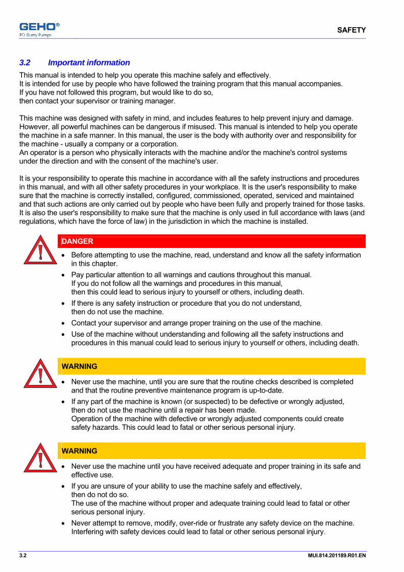
3.2 Important information Pos: 5.6 /GEHO/Safety/General/Important information @ 0\mod_1137680237357_31.doc @ 1362
This manual is intended to help you operate this machine safely and effectively. It is intended for use by people who have followed the training program that this manual accompanies. If you have not followed this program, but would like to do so, then contact your supervisor or training manager. This machine was designed with safety in mind, and includes features to help prevent injury and damage. However, all powerful machines can be dangerous if misused. This manual is intended to help you operate the machine in a safe manner. In this manual, the user is the body with authority over and responsibility for the machine - usually a company or a corporation. An operator is a person who physically interacts with the machine and/or the machine's control systems under the direction and with the consent of the machine's user. It is your responsibility to operate this machine in accordance with all the safety instructions and procedures in this manual, and with all other safety procedures in your workplace. It is the user's responsibility to make sure that the machine is correctly installed, configured, commissioned, operated, serviced and maintained and that such actions are only carried out by people who have been fully and properly trained for those tasks. It is also the user's responsibility to make sure that the machine is only used in full accordance with laws (and regulations, which have the force of law) in the jurisdiction in which the machine is installed.
DANGER
• Before attempting to use the machine, read, understand and know all the safety information
in this chapter. • Pay particular attention to all warnings and cautions throughout this manual.
If you do not follow all the warnings and procedures in this manual, then this could lead to serious injury to yourself or others, including death.
• If there is any safety instruction or procedure that you do not understand, then do not use the machine.
• Contact your supervisor and arrange proper training on the use of the machine. • Use of the machine without understanding and following all the safety instructions and
procedures in this manual could lead to serious injury to yourself or others, including death.
WARNING
• Never use the machine, until you are sure that the routine checks described is completed and that the routine preventive maintenance program is up-to-date.
• If any part of the machine is known (or suspected) to be defective or wrongly adjusted, then do not use the machine until a repair has been made. Operation of the machine with defective or wrongly adjusted components could create safety hazards. This could lead to fatal or other serious personal injury.
WARNING
• Never use the machine until you have received adequate and proper training in its safe and effective use.
• If you are unsure of your ability to use the machine safely and effectively, then do not do so. The use of the machine without proper and adequate training could lead to fatal or other serious personal injury.
• Never attempt to remove, modify, over-ride or frustrate any safety device on the machine. Interfering with safety devices could lead to fatal or other serious personal injury.
Pos: 5.7 /--- Page break --- @ 0\mod_1136278659331_0.doc @ 766

SAFETY
MUI.814.201189.R01.EN 3.3
Pos: 5.8 /GEHO/Heading/H2/#.# Intended use @ 0\mod_1138263061409_31.doc @ 1911
3.3 Intended use Pos: 5.9 /GEHO/Safety/Product Safety/Intended use @ 0\mod_1138263117509_31.doc @ 1914
This pump is intended to pump a liquid media only. The liquid media is specified by the customer.
Refer to the chapter “Technical data” for a detailed specification. Pos: 5.10 /GEHO/Heading/H2/#.# General safety instructions @ 0\mod_1133271158987_31.doc @ 206
3.4 General safety instructions Pos: 5.11 /GEHO/Safety/Product Safety/General safety instructions @ 0\mod_1133426798361_31.doc @ 244
• Always obey local safety regulations and instructions. • Never cause a potentially dangerous situation. • Never touch moving parts. • Never loosen parts under pressure. • Never touch parts with high temperature. • Never touch parts under electrical power. • Never touch parts which contain dangerous or poisonous media. Pos: 5.12 /GEHO/Heading/H2/#.# Qualified workers @ 0\mod_1133271087294_31.doc @ 203
3.5 Qualified workers Pos: 5.13 /GEHO/Safety/Product Safety/Qualified workers @ 0\mod_1133271624877_31.doc @ 219
• Only personnel who have been given permission are allowed to work with or on the machine. • All personnel must only carry out the work they have been trained to perform.
This applies to both maintenance work and the normal machine operation. • All personnel working with or on the machine must have free access to the applicable manuals. • The operators must be familiar with all situations that may occur so that they can act rapidly and effectively
in the event of emergencies. Pos: 5.14 /GEHO/Heading/H2/#.# Working on the pump @ 0\mod_1133271313769_31.doc @ 209
3.6 Working on the pump Pos: 5.15 /GEHO/Safety/Product Safety/Working on the pump @ 0\mod_1133428079834_31.doc @ 250
• Switch off the main power supply and secure the equipment against switching on. • Never loosen any parts containing pressure, hot or dangerous fluids. Pos: 5.16 /GEHO/Heading/H2/#.# Efficient use @ 0\mod_1133271247864_31.doc @ 207
3.7 Efficient use Pos: 5.17 /GEHO/Safety/Product Safety/Efficient use @ 0\mod_1133427598361_31.doc @ 248
• Apply correct and regular maintenance, according to these operating instructions. • Always use genuine GEHO spare parts and wear parts. Pos: 5.18 /GEHO/Heading/H2/#.# Safety equipment @ 0\mod_1137483401931_31.doc @ 1241
3.8 Safety equipment Pos: 5.19 /GEHO/Safety/Product Safety/### Safety related documentation @ 4\mod_1215006153706_31.doc @ 36725
3.8.1 Safety related documentation
DANGER
If applicable, than refer to the book "MANUFACTURING DATA RECORDS" ("MDR") of this pump for the documentation about CE conformity (as defined by the European "Directive on machinery 98/37/EC and 2006/42/EC") and other required safety related documentation.
Pos: 5.20 /GEHO/Safety/Product Safety/### DANGER: CE conformity @ 4\mod_1214979575442_31.doc @ 36701
3.8.2 CE conformity
DANGER
If failing to install and maintain the SAFETY EQUIPMENT in accordance with this manual, then the installation is no longer in CE-conformity (as defined by the European "Directive on machinery 98/37/EC and 2006/42/EC") and thus results in: "... machinery must not be put into service until the final machinery into which it is to be incorporated has been declared in conformity with the provisions of this Directive ..."
Pos: 5.21 /GEHO/Heading/H3/#.#.# Emergency stop button @ 0\mod_1137486628771_31.doc @ 1245

SAFETY
3.4 MUI.814.201189.R01.EN
3.8.3 Emergency stop button Pos: 5.22 /GEHO/Safety/Product Safety/DANGER: emergency button @ 4\mod_1214979911686_31.doc @ 36709
CE conformity
DANGER
If failing to install and maintain the EMERGENCY BUTTON equipment in accordance with this manual, then the installation is no longer in CE-conformity (as defined by the European "Directive on machinery 98/37/EC and 2006/42/EC") and thus results in: "... machinery must not be put into service until the final machinery into which it is to be incorporated has been declared in conformity with the provisions of this Directive ..."
Pos: 5.23 /GEHO/Safety/Product Safety/Emergency stop button @ 0\mod_1137483963358_31.doc @ 1243
Refer to chapter "Start and Stop procedure" for details about the use of the EMERGENCY STOP button.
According to local regulations an emergency stop button must be provided by the customer.
It is mandatory to install an EMERGENCY STOP button within a short range of the pump installation. The installation of the EMERGENCY STOP system is not within the scope of the contract between the customer and Weir Minerals Netherlands. Responsible for the installation of the EMERGENCY STOP button is the customer, as stated in the written contract.
INFORMATION
• An emergency stop situation is defined in the EN 60204 standard. • An emergency stop is a human action in case of emergency, which is determined to stop a
process or movement that could cause an unsafe situation. • An emergency stop has priority towards all functions and controls in all kind of modes. • Reset an emergency stop may not cause an automatic restart. • Functional aspects for ‘switching off at emergency’ as described in the international
document IEC 60364 or NEC should be observed. • The final customer emergency stop design must be in accordance to the concerning risk
class and all local regulations. • If no MCC (motor control center) hardware is in the manufacturer’s scope of supply,
then an emergency stop will not be added, due to lack of MCC configuration information. Pos: 5.24 /GEHO/Heading/H3/#.#.# Safety covers and safety guards @ 0\mod_1137486661628_31.doc @ 1247
3.8.4 Safety covers and safety guards Pos: 5.25 /GEHO/Safety/Product Safety/### Safety covers and safety guards @ 0\mod_1137486711069_31.doc @ 1249
The equipment has safety covers and safety guards at all potential unsafe parts.
• Safety covers and safety guards must remain in place during operation. • Safety covers and safety guards may only be removed by qualified personnel for maintenance or service
work. Pos: 6 /--- Section break - Odd page --- @ 0\mod_1136277036628_0.doc @ 765

Technical data
MUI.814.201189.R01.EN 4.1
Pos: 7 /GEHO/Heading/H1/#. Technical data @ 0\mod_1133269719867_31.doc @ 179
4 Technical data Pos: 8.1 /GEHO/Heading/H2/#.# Project information @ 0\mod_1133269813171_31.doc @ 181
4.1 Project information Pos: 8.2 /GEHO/Technical data sheets/Project information @ 0\mod_1133439392901_31.doc @ 273
WEIR Project information WEIR Project name
WEIR Project number
Customer purchase order number
Pos: 8.3 /GEHO/Heading/H2/#.# Customer information @ 0\mod_1133443655420_31.doc @ 291
4.2 Customer information Pos: 8.4 /GEHO/Technical data sheets/Project/201189/Customer information @ 5\mod_1225113509954_31.doc @ 39807
Customer information Name
Address
Pos: 8.5 /GEHO/Heading/H2/#.# Manufacturer information @ 0\mod_1133443515208_31.doc @ 288
4.3 Manufacturer information Pos: 8.6 /GEHO/Technical data sheets/Manufacturer information @ 0\mod_1133272928581_31.doc @ 221
Manufacturer information Name Weir Minerals Netherlands b.v.
Address P.O. Box 249 NL5900AE - VENLO, the Netherlands
Phone (+31) 77-3895200
Fax (+31) 77-3824844
E-mail [email protected]
Website, internet http://www.weirminerals.com
Department Installation, Commissioning
Phone (+31) 77-3895141
Fax (+31) 77-3824844: V. van der Koelen
Department Spare Parts
Phone (+31) 77-3895236
Fax (+31) 77-3824844: R. Reijnders Pos: 8.7 /--- Page break --- @ 0\mod_1136278659331_0.doc @ 766

Technical data
4.2 MUI.814.201189.R01.EN
Pos: 8.8 /GEHO/Heading/H2/#.# Technical data @ 0\mod_1133270813820_31.doc @ 198
4.4 Technical data Pos: 8.9 /GEHO/Heading/H3/#.#.# Operating characteristics @ 0\mod_1133443294151_31.doc @ 286
4.4.1 Operating characteristics Pos: 8.10 /GEHO/Technical data sheets/Project/201189/Operation characteristics @ 5\mod_1225113512235_31.doc @ 39843
Operation characteristics Location of the equipment Underground
Site elevation 990 meter underground
Liquid to be pumped Liquid, dirty mine water max. 5% solids < 2mm
Minimum slurry temperature Not available
Operating slurry temperature Not available
Maximum slurry temperature 50°C
Specific slurry gravity 1.05 [ - ]
Maximum solid diameter 2 mm
Solid concentration, normal 150%
Solid concentration, maximum 5%
Maximum viscosity Not available
pH value 6 - 8.5
Pos: 8.11 /--- Page break --- @ 0\mod_1136278659331_0.doc @ 766
Technical data
MUI.814.201189.R01.EN 4.3
Pos: 8.12 /GEHO/Heading/H3/#.#.# Pump and project data @ 0\mod_1133444066872_31.doc @ 292
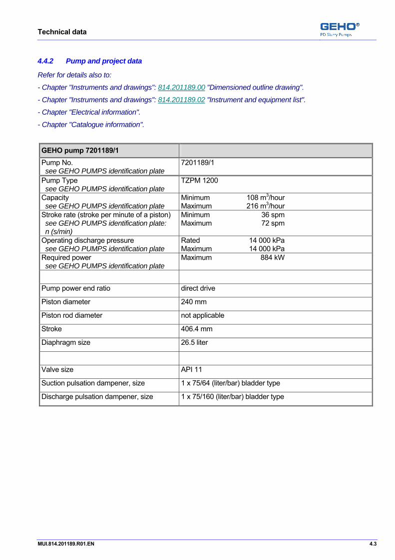
4.4.2 Pump and project data Pos: 8.13 /GEHO/Technical data sheets/Project/201189/GEHO PUMPS data @ 5\mod_1225113511000_31.doc @ 39825
Refer for details also to:
- Chapter "Instruments and drawings": 814.201189.00 "Dimensioned outline drawing".
- Chapter "Instruments and drawings": 814.201189.02 "Instrument and equipment list".
- Chapter "Electrical information".
- Chapter "Catalogue information".
GEHO pump 7201189/1 Pump No. see GEHO PUMPS identification plate
7201189/1
Pump Type see GEHO PUMPS identification plate
TZPM 1200
Capacity see GEHO PUMPS identification plate
Minimum 108 m3/hour Maximum 216 m3/hour
Stroke rate (stroke per minute of a piston) see GEHO PUMPS identification plate: n (s/min)
Minimum 36 spm Maximum 72 spm
Operating discharge pressure see GEHO PUMPS identification plate
Rated 14 000 kPa Maximum 14 000 kPa
Required power see GEHO PUMPS identification plate
Maximum 884 kW
Pump power end ratio direct drive
Piston diameter 240 mm
Piston rod diameter not applicable
Stroke 406.4 mm
Diaphragm size 26.5 liter
Valve size API 11
Suction pulsation dampener, size 1 x 75/64 (liter/bar) bladder type
Discharge pulsation dampener, size 1 x 75/160 (liter/bar) bladder type
Pos: 8.14 /--- Page break --- @ 0\mod_1136278659331_0.doc @ 766

Technical data
4.4 MUI.814.201189.R01.EN
Pos: 8.15 /GEHO/Heading/H4/Connection - Electrical @ 0\mod_1133446672849_31.doc @ 306
4.4.2.1 Electrical connection Pos: 8.16 /GEHO/Technical data sheets/Voltage/Australia 6600/50/3 - 415/50/3 - 24/DC @ 5\mod_1225985403284_31.doc @ 40203
Item Voltage [V] Frequency [Hz] Phases Main motor 6600 50 3
Auxiliary motors 415 50 3
Control panel HMI 24V DC Pos: 8.17 /GEHO/Heading/H4/Pump drive @ 0\mod_1133448795551_31.doc @ 321
4.4.2.2 Pump drive Pos: 8.18 /GEHO/Technical data sheets/Main E-motor/TECO - AELN-WT001 @ 5\mod_1225985733972_31.doc @ 40211
Main E-motor Refer to "Appendix: Catalog" Manufacturer Teco
Type / size AELN-WT001
Voltage 6600 V – 50 Hz – 3 Phases
Pos: 8.19 /GEHO/Technical data sheets/Frequency converter/Customer supplied @ 0\mod_1137065501172_31.doc @ 1138
Frequency converter Manufacturer Customer supplied
Type n/a
Pos: 8.20 /GEHO/Technical data sheets/Gearbox/Flender - B3SH 18-3 @ 5\mod_1225986096752_31.doc @ 40221
Gearbox 814.201189.31 Manufacturer Flender
Type B3SH 18-3
Power rating max. 884 kW
Input speed 146.5 – 1465 rpm
Output speed 7.2 – 72 rpm
Gearbox ratio 20.348
Gear cooling External oil-to-air heat exchanger Pos: 8.21 /GEHO/Heading/H4/Shaft coupling @ 0\mod_1133540284412_31.doc @ 341
4.4.2.3 Shaft couplings Pos: 8.22 /GEHO/Technical data sheets/Shaft coupling/Flender - RUPEX RWN 450 @ 5\mod_1226319163120_31.doc @ 40337
E-motor / Gearbox Refer to "Catalogue information" for details.
Manufacturer Flender
Type RUPEX RWN 450
Pos: 8.23 /GEHO/Technical data sheets/Shaft coupling/Flender - ZAPEX ZWN 545A @ 0\mod_1133540782858_31.doc @ 346
Pump shaft / Gearbox Refer to "Catalogue information" for details.
Manufacturer Flender
Type ZAPEX ZWN 545A
Pos: 8.24 /GEHO/Heading/H2/#.# Tightening torques @ 0\mod_1133269909891_31.doc @ 183
Technical data
MUI.814.201189.R01.EN 4.5
4.5 Tightening torques Pos: 8.25.1 /GEHO/Heading/H3/#.#.# General torques @ 0\mod_1133270125801_31.doc @ 190
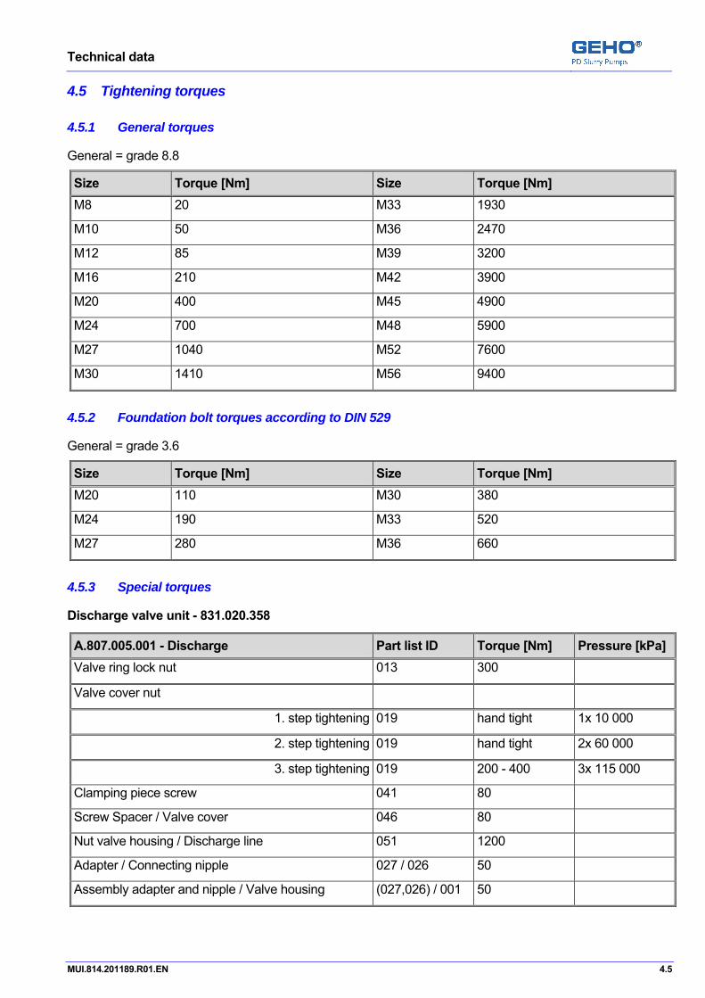
4.5.1 General torques Pos: 8.25.2 /GEHO/Technical data sheets/General torques/General torques - grade 8.8 Nm @ 0\mod_1133862945227_31.doc @ 392
General = grade 8.8
Size Torque [Nm] Size Torque [Nm] M8 20 M33 1930
M10 50 M36 2470
M12 85 M39 3200
M16 210 M42 3900
M20 400 M45 4900
M24 700 M48 5900
M27 1040 M52 7600
M30 1410 M56 9400 Pos: 8.26.1 /GEHO/Heading/H3/#.#.# Foundation bolt torques according to DIN 529 @ 0\mod_1133863490701_31.doc @ 397
4.5.2 Foundation bolt torques according to DIN 529 Pos: 8.26.2 /GEHO/Technical data sheets/General torques/Foundation bolt torques - grade 3.6 Nm @ 0\mod_1133863255313_31.doc @ 395
General = grade 3.6
Size Torque [Nm] Size Torque [Nm] M20 110 M30 380
M24 190 M33 520
M27 280 M36 660 Pos: 8.27.1 /GEHO/Heading/H3/#.#.# Special torques @ 0\mod_1133270014401_31.doc @ 187
4.5.3 Special torques Pos: 8.27.2 /GEHO/Technical data sheets/Special torques/Discharge valve unit/H.831.020.358 @ 3\mod_1196337642082_31.doc @ 19844
Discharge valve unit - 831.020.358 Pos: 8.27.3 /GEHO/Technical data sheets/Special torques/A-Specification/A.807.005.001 - Discharge @ 5\mod_1226320766581_31.doc @ 40345
A.807.005.001 - Discharge Part list ID Torque [Nm] Pressure [kPa] Valve ring lock nut 013 300
Valve cover nut
1. step tightening 019 hand tight 1x 10 000
2. step tightening 019 hand tight 2x 60 000
3. step tightening 019 200 - 400 3x 115 000
Clamping piece screw 041 80
Screw Spacer / Valve cover 046 80
Nut valve housing / Discharge line 051 1200
Adapter / Connecting nipple 027 / 026 50
Assembly adapter and nipple / Valve housing (027,026) / 001 50
Pos: 8.27.4 /GEHO/Technical data sheets/Special torques/Suction valve unit/H.831.020.359 @ 3\mod_1196341283886_31.doc @ 19856
Technical data
4.6 MUI.814.201189.R01.EN
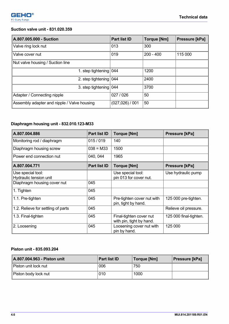
Suction valve unit - 831.020.359 Pos: 8.27.5 /GEHO/Technical data sheets/Special torques/A-Specification/A.807.005.000 - Suction @ 5\mod_1226561554715_31.doc @ 43682
A.807.005.000 - Suction Part list ID Torque [Nm] Pressure [kPa] Valve ring lock nut 013 300
Valve cover nut 019 200 - 400 115 000
Nut valve housing / Suction line
1. step tightening 044 1200
2. step tightening 044 2400
3. step tightening 044 3700
Adapter / Connecting nipple 027 / 026 50
Assembly adapter and nipple / Valve housing (027,026) / 001 50
Pos: 8.27.6 /GEHO/Technical data sheets/Special torques/Diaphragm housing unit/H.832.010.123-M33 @ 2\mod_1178895354267_31.doc @ 13654
Diaphragm housing unit - 832.010.123-M33 Pos: 8.27.7 /GEHO/Technical data sheets/Special torques/A-Specification/A.807.004.886+A.807.004.771 hydr.diap.house @ 0\mod_1138890120655_31.doc @ 2327
A.807.004.886 Part list ID Torque [Nm] Pressure [kPa] Monitoring rod / diaphragm 015 / 019 140
Diaphragm housing screw 038 = M33 1500
Power end connection nut 040, 044 1965
A.807.004.771 Part list ID Torque [Nm] Pressure [kPa] Use special tool: Hydraulic tension unit
Use special tool: pin 013 for cover nut.
Use hydraulic pump
Diaphragm housing cover nut 045
1. Tighten 045
1.1. Pre-tighten 045 Pre-tighten cover nut with pin, tight by hand.
125 000 pre-tighten.
1.2. Relieve for settling of parts 045 Relieve oil pressure.
1.3. Final-tighten 045 Final-tighten cover nut with pin, tight by hand.
125 000 final-tighten.
2. Loosening 045 Loosening cover nut with pin by hand.
125 000
Pos: 8.27.8 /GEHO/Technical data sheets/Special torques/Piston unit/H.835.093.204 @ 3\mod_1205919947109_31.doc @ 27523
Piston unit - 835.093.204 Pos: 8.27.9 /GEHO/Technical data sheets/Special torques/A-Specification/A.807.004.963 Piston unit @ 3\mod_1205941932311_31.doc @ 27576
A.807.004.963 - Piston unit Part list ID Torque [Nm] Pressure [kPa] Piston unit lock nut 006 750
Piston body lock nut 010 1000 Pos: 8.27.10 /GEHO/Technical data sheets/Special torques/Pulsation damper unit/H.851.010.115 @ 2\mod_1188801674043_31.doc @ 14987

Technical data
MUI.814.201189.R01.EN 4.7
Pulsation damper unit - 851.010.115 Pos: 8.27.11 /GEHO/Technical data sheets/Special torques/A-Specification/A.807.004.894=75/160 puls.damp. @ 2\mod_1188801803467_31.doc @ 14992
A.807.004.894 Part list ID Torque [Nm] Pressure [kPa] Pulsation damper flange screw 013 1060
Pulsation damper cover nut 014 2800 Pos: 8.27.12 /GEHO/Technical data sheets/Special torques/Pressure limitation regulation unit/H.853.010.251 @ 2\mod_1193298411076_31.doc @ 18740
Pressure limitation regulation unit - 853.010.251 Pos: 8.27.13 /GEHO/Technical data sheets/Special torques/A-Specification/A.807.004.883 @ 2\mod_1181215948540_31.doc @ 13907
A.807.004.883 Part list ID Torque [Nm] Pressure [kPa] Nut Safety valve / Drain line 010 350
Pos: 8.27.14 /GEHO/Technical data sheets/Special torques/Pulsation damper unit/H.851.010.092 @ 2\mod_1188563881248_31.doc @ 14905
Pulsation damper unit - 851.010.094 Pos: 8.27.15 /GEHO/Technical data sheets/Special torques/A-Specification/A.807.004.650-851.010.092=75/64 puls.damp. @ 3\mod_1204642384820_31.doc @ 27032
A.807.004.650 Part list ID Torque [Nm] Pressure [kPa] Pulsation damper cover nut 014 1290
Pos: 8.27.16 /GEHO/Technical data sheets/Special torques/Special tools/H.897.010.710 @ 3\mod_1197678887995_31.doc @ 24914
Special tool: Hydraulic pump unit - 897.010.710 Pos: 8.27.17 /GEHO/Technical data sheets/Special torques/A-Specification/A.807.004.622 Hydr.pump-imp @ 0\mod_1143217678540_31.doc @ 2882
A.807.004.622 Part list ID Torque Pressure Adapter / connecting nipple 002 / 003 50 Nm
37 LB-FT
Hydraulic unit, with hose 002 / 003 maximum 200 000 kPa 2 000 bar 29 000 psig
WARNING: NEVER pressurize the pump, if it is not connected with the hose to a tool. For this can damage the sealing ring at the quick release connectors ("nipples").
002 / 004 Non
Pos: 8.28 /GEHO/Heading/H2/#.# Auxiliary connections and Lubrication data @ 0\mod_1137667733207_31.doc @ 1351
4.6 Auxiliary connections and lubrication data Pos: 8.29 /GEHO/Technical data sheets/Refer to Utility consumption list @ 0\mod_1148974052988_31.doc @ 4381
Refer to the “Utility consumption list” for more information about auxiliary connections and lubrication data.
Pos: 8.30 /GEHO/Heading/H2/#.# Drawings+Lists+Instruments @ 0\mod_1133876951146_31.doc @ 421
Technical data
4.8 MUI.814.201189.R01.EN
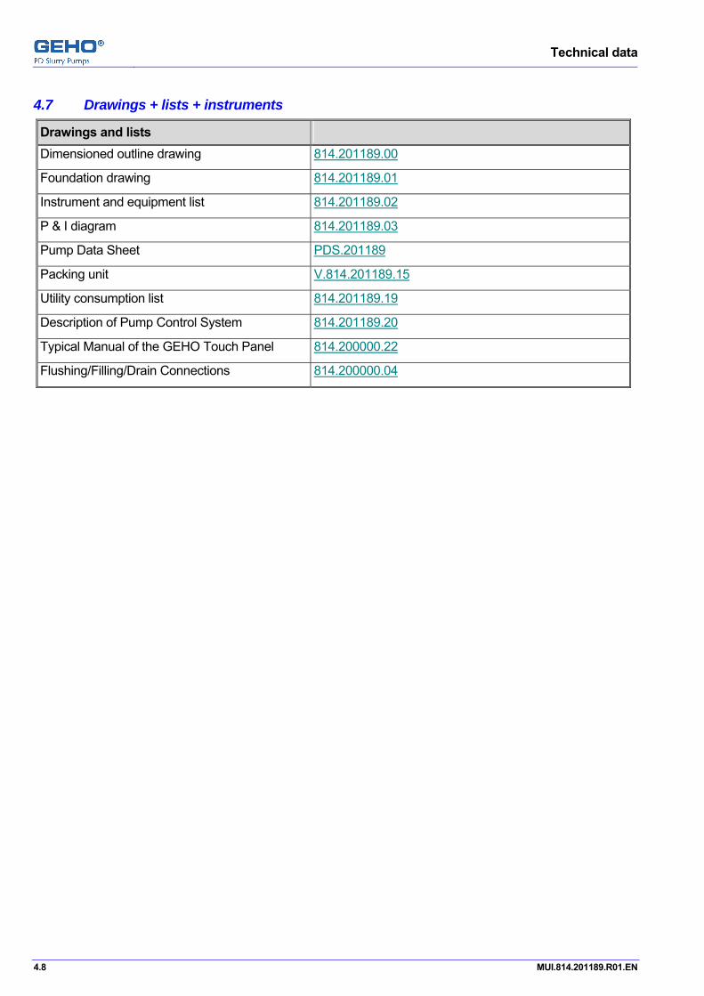
4.7 Drawings + lists + instruments Pos: 8.31 /GEHO/Technical data sheets/Project/201189/Instrument and drawings @ 5\mod_1225113511579_31.doc @ 39834
Drawings and lists Dimensioned outline drawing 814.201189.00
Foundation drawing 814.201189.01
Instrument and equipment list 814.201189.02
P & I diagram 814.201189.03
Pump Data Sheet PDS.201189
Packing unit V.814.201189.15
Utility consumption list 814.201189.19
Description of Pump Control System 814.201189.20
Typical Manual of the GEHO Touch Panel 814.200000.22
Flushing/Filling/Drain Connections 814.200000.04 Pos: 9 /--- Section break - Odd page --- @ 0\mod_1136277036628_0.doc @ 765
Description
MUI.814.201189.R01.EN 5.1
Pos: 10.1 /GEHO/Heading/H1/#. Description @ 0\mod_1134483846926_31.doc @ 448
5 Description Pos: 10.2.1 /GEHO/Heading/H2/#.# Introduction @ 0\mod_1144834888602_31.doc @ 3092
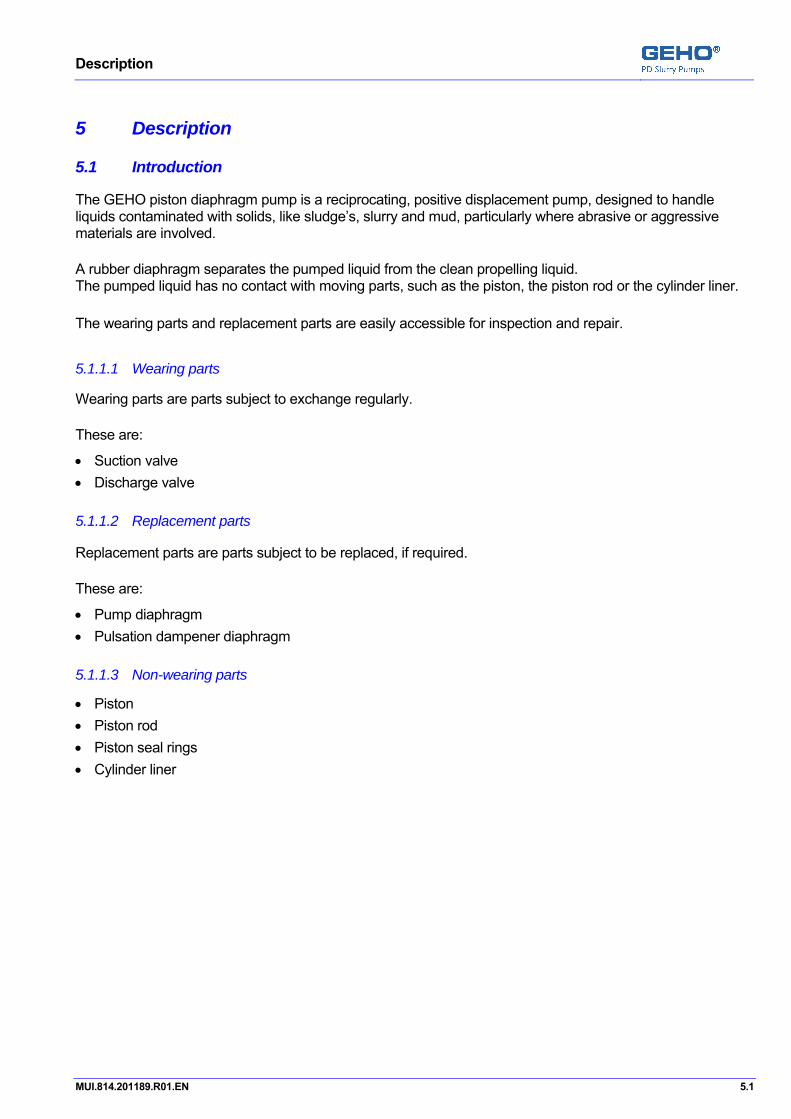
5.1 Introduction Pos: 10.2.2 /GEHO/Description/Introduction/Media @ 0\mod_1134634042426_31.doc @ 544
The GEHO piston diaphragm pump is a reciprocating, positive displacement pump, designed to handle liquids contaminated with solids, like sludge’s, slurry and mud, particularly where abrasive or aggressive materials are involved. Pos: 10.2.3 /GEHO/Description/Introduction/Diaphragm unit @ 0\mod_1134633771977_31.doc @ 542
A rubber diaphragm separates the pumped liquid from the clean propelling liquid. The pumped liquid has no contact with moving parts, such as the piston, the piston rod or the cylinder liner. Pos: 10.2.4 /GEHO/Description/Introduction/Wearing and replacement parts @ 0\mod_1134635894018_31.doc @ 574
The wearing parts and replacement parts are easily accessible for inspection and repair. Pos: 10.2.5 /GEHO/Heading/H4/Wearing parts @ 0\mod_1134635462418_31.doc @ 560
5.1.1.1 Wearing parts Pos: 10.2.6 /GEHO/Description/Introduction/Wearing parts: Definition @ 0\mod_1134639095462_31.doc @ 580
Wearing parts are parts subject to exchange regularly. Pos: 10.2.7 /GEHO/Description/Introduction/Wearing parts: List @ 0\mod_1134635624621_31.doc @ 570
These are:
• Suction valve • Discharge valve Pos: 10.2.8 /GEHO/Heading/H4/Replacement parts @ 0\mod_1134635502866_31.doc @ 564
5.1.1.2 Replacement parts Pos: 10.2.9 /GEHO/Description/Introduction/Replacement parts: Definition @ 0\mod_1134639331822_31.doc @ 582
Replacement parts are parts subject to be replaced, if required. Pos: 10.2.10 /GEHO/Description/Introduction/Replacement parts: List @ 0\mod_1134635786604_31.doc @ 572
These are:
• Pump diaphragm • Pulsation dampener diaphragm Pos: 10.2.11 /GEHO/Heading/H4/Non-wearing parts @ 0\mod_1134635392998_31.doc @ 555
5.1.1.3 Non-wearing parts Pos: 10.2.12 /GEHO/Description/Introduction/TZPM/Non-wearing parts @ 0\mod_1134634939436_31.doc @ 554
• Piston • Piston rod • Piston seal rings • Cylinder liner Pos: 10.3 /--- Page break --- @ 0\mod_1136278659331_0.doc @ 766
Description
5.2 MUI.814.201189.R01.EN
Pos: 10.4.1 /GEHO/Heading/H2/#.# Working principle @ 0\mod_1135000311087_31.doc @ 611
5.2 Working principle Pos: 10.4.2 /GEHO/Description/Working principle/TZPM/TZPM general @ 2\mod_1176882885858_31.doc @ 13241
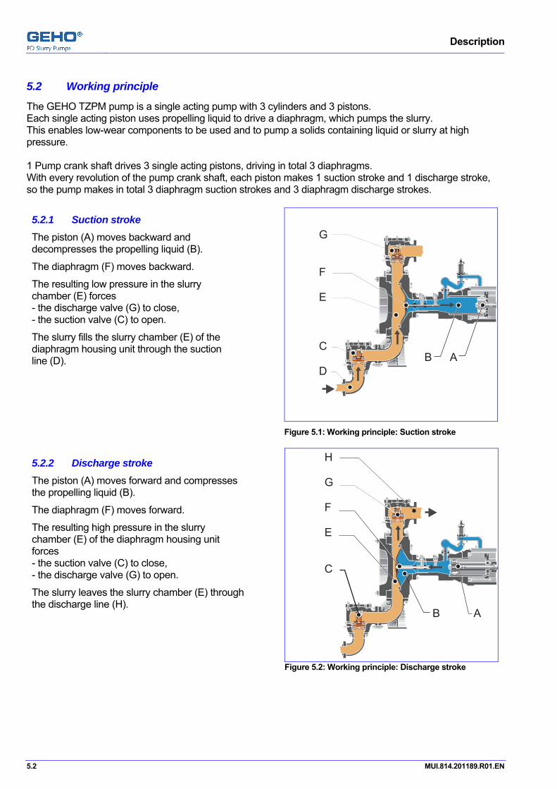
The GEHO TZPM pump is a single acting pump with 3 cylinders and 3 pistons. Each single acting piston uses propelling liquid to drive a diaphragm, which pumps the slurry. This enables low-wear components to be used and to pump a solids containing liquid or slurry at high pressure. 1 Pump crank shaft drives 3 single acting pistons, driving in total 3 diaphragms. With every revolution of the pump crank shaft, each piston makes 1 suction stroke and 1 discharge stroke, so the pump makes in total 3 diaphragm suction strokes and 3 diaphragm discharge strokes. Pos: 10.4.3 /GEHO/Description/Working principle/TZPM/Suction stroke @ 0\mod_1134999056904_31.doc @ 606
5.2.1 Suction stroke The piston (A) moves backward and decompresses the propelling liquid (B).
The diaphragm (F) moves backward.
The resulting low pressure in the slurry chamber (E) forces - the discharge valve (G) to close, - the suction valve (C) to open.
The slurry fills the slurry chamber (E) of the diaphragm housing unit through the suction line (D).
AB
G
F
E
C
D
Figure 5.1: Working principle: Suction stroke
Pos: 10.4.4 /GEHO/Description/Working principle/TZPM/Discharge stroke @ 0\mod_1134999494473_31.doc @ 608
5.2.2 Discharge stroke The piston (A) moves forward and compresses the propelling liquid (B).
The diaphragm (F) moves forward.
The resulting high pressure in the slurry chamber (E) of the diaphragm housing unit forces - the suction valve (C) to close, - the discharge valve (G) to open.
The slurry leaves the slurry chamber (E) through the discharge line (H).
H
G
F
E
C
B A
Figure 5.2: Working principle: Discharge stroke Pos: 10.5 /--- Page break --- @ 0\mod_1136278659331_0.doc @ 766

Description
MUI.814.201189.R01.EN 5.3
Pos: 10.6.1 /GEHO/Heading/H2/#.# Drive unit @ 0\mod_1134483988099_31.doc @ 452
5.3 Drive unit Pos: 10.6.2 /GEHO/Description/Drive unit/Gearbox type @ 0\mod_1134639813244_31.doc @ 584
• The main E-motor and the gearbox are mounted on a one structure welded base frame. • The mounting surfaces for these components are machined to allow optimum alignment. • Anchoring holes in the bottom of the base frame are provided. • The main E-motor shaft and the gearbox input shaft are connected with a flexible shaft coupling. • The gearbox output shaft and the pump shaft are connected with a gear coupling. • Coupling guards are provided for safety. Pos: 10.7 /GEHO/Heading/H2/#.# Power end @ 0\mod_1134484023820_31.doc @ 454
5.4 Power end Pos: 10.8 /GEHO/Description/Power end/Introduction/Introduction @ 0\mod_1136371259991_31.doc @ 916
The power end converts the circular motion of the pump drive into a linear motion of the connecting rod and crosshead and piston. Pos: 10.9 /GEHO/Description/Power end/Project/201189=TZPM 1200 @ 5\mod_1226500711865_31.doc @ 43622
The power end includes the following items:
• Cast power end with shaft seals and inspection covers to seal against exterior contamination. • Direct driven crankshaft. • Forged alloy steel crankshaft supported on self-aligning roller bearings. • Heavy duty anti-friction bearings. • Crossheads with replaceable guides. • Crosshead extension/piston rods constructed in sections for simple replacement of the pistons. • Integral pressurized lube oil system. • Piston rod stuffing box to prevent lube oil contamination and leakage. • A turning gear device for manually rotating the pump in an unloaded condition. • Lock-out of the motor driver when the turning gear is engaged. Pos: 10.10.1 /GEHO/Heading/H3/#.#.# Lubrication unit @ 0\mod_1134568393543_31.doc @ 498
5.4.1 Lubrication unit Pos: 10.10.2 /GEHO/Description/Power end/Lubrication unit/TZPM/Introduction @ 0\mod_1136372541764_31.doc @ 918
The lubrication unit supplies fresh oil to the bearings, the crosshead liners and the crosshead rod. Pos: 10.11 /GEHO/Heading/H2/#.# Liquid end @ 0\mod_1134568182139_31.doc @ 492
5.5 Liquid end Pos: 10.12.1 /GEHO/Description/Liquid end/Introduction/TZPM/Main items - TZPM - Header @ 0\mod_1145875032918_31.doc @ 3323
The TZPM pump consist of the following parts: Pos: 10.12.2 /GEHO/Description/Liquid end/Introduction/TZPM/Main items - TZPM @ 0\mod_1136360416839_31.doc @ 882
• 3 Piston units. • 3 Diaphragm housing units. • 3 Suction valve units. • 1 Suction manifold. • 3 Discharge valve units. • 1 Discharge manifold. Pos: 10.12.3 /GEHO/Description/Liquid end/Introduction/Main items/ Pulsation dampener - Suction (1) @ 1\mod_1173099006839_31.doc @ 12590
• 1 Suction pulsation dampener. Pos: 10.12.4 /GEHO/Description/Liquid end/Introduction/Main items/Pulsation dampener - Discharge (1) @ 0\mod_1135002171112_31.doc @ 623
• 1 Discharge pulsation dampener. Pos: 10.12.5 /GEHO/Description/Liquid end/Introduction/Divisions @ 0\mod_1149662408190_31.doc @ 4417
The liquid end is divided by a rubber diaphragm into two mechanically separated sections:
• The propelling liquid section. • The slurry section.

Description
5.4 MUI.814.201189.R01.EN
Pos: 10.12.6 /GEHO/Description/Liquid end/Introduction/Propelling liquid section/TZPM @ 1\mod_1166113655949_31.doc @ 11322
5.5.1 The propelling liquid section The propelling liquid section is filled with the propelling liquid.
The propelling liquid section consists of:
• The piston unit. • The rear side of the diaphragm housing unit. Pos: 10.12.7 /GEHO/Description/Liquid end/Introduction/Slurry section/Standard @ 0\mod_1149662677848_31.doc @ 4423
5.5.2 The slurry section Only the slurry section has contact with the pumped liquid.
The slurry section consists of:
• The slurry front side of the diaphragm housing unit. • The suction valve unit. • The discharge valve unit. Pos: 10.12.8 /GEHO/Description/Liquid end/Introduction/Main items/ Pulsation dampener - Suction (1) @ 1\mod_1173099006839_31.doc @ 12590
• 1 Suction pulsation dampener. Pos: 10.12.9 /GEHO/Description/Liquid end/Introduction/Main items/Pulsation dampener - Discharge (1) @ 0\mod_1135002171112_31.doc @ 623
• 1 Discharge pulsation dampener. Pos: 10.13.1 /GEHO/Heading/H3/#.#.# Piston unit @ 0\mod_1134569925466_31.doc @ 512
5.5.3 Piston unit Pos: 10.13.2 /GEHO/Description/Liquid end/Piston unit/TZPM/Piston rod - Tapered @ 0\mod_1145878938338_31.doc @ 3329
The piston rod connects the piston and the crosshead rod. The tapered ends are connected by the rod clamping piece. Pos: 10.13.3 /GEHO/Description/Liquid end/Piston unit/Piston @ 0\mod_1135242883584_31.doc @ 732
The piston is provided with two sets of roof shaped rings (piston seal rings) and a piston guide ring.
The piston guide ring centers the piston in the cylinder liner. Pos: 10.13.4 /GEHO/Description/Liquid end/Piston unit/TZPM/Piston seal rings @ 0\mod_1135069059470_31.doc @ 661
The piston seal to the propelling section prevents loss of propelling liquid from the diaphragm housing. The piston seal ring to the air side prevents drawing in of air or drawing in of flushing liquid. Pos: 10.13.5 /GEHO/Description/Liquid end/Piston unit/TZPM/Cylinder liner @ 0\mod_1135069465694_31.doc @ 666
The cylinder liner is clamped into the diaphragm housing end by a thrust piece. Pos: 10.13.6 /GEHO/Description/Liquid end/Piston unit/Resistance and replacement @ 0\mod_1135070106045_31.doc @ 670
The cylinder liner is highly wear resistant. It is not damaged immediately, when as a result of diaphragm rupture the abrasive solids enter the propelling liquid section. The piston body and the cylinder liner can be changed quickly and easily.
Pos: 10.14 /--- Page break --- @ 0\mod_1136278659331_0.doc @ 766

Description
MUI.814.201189.R01.EN 5.5
Pos: 10.15.1 /GEHO/Heading/H3/#.#.# Propelling liquid control system @ 0\mod_1134632211894_31.doc @ 522
5.5.4 Propelling liquid control system Pos: 10.15.2 /GEHO/Description/Liquid end/Propelling liquid control system/TZPM/TZPM schematics @ 0\mod_1135261173624_31.doc @ 755
AE BCDF
G
H
I
PLC
K
L
J4 FILL 5 DRAIN
12
3
Figure 5.3: TZPM pump schematics
A Slurry suction line B Slurry chamber C Propelling liquid D Suction valve E Diaphragm F Piston G Piston rod H Cylinder liner I Monitoring rod with a position marker
for limitation of the diaphragm stroke J Discharge valve
K Slurry discharge line L Monitoring probes for minimum and maximum stroke of the diaphragm (for limitation of the diaphragm stroke) 1 AIR = Compressed air supply connection 2 Propelling liquid automatic control system 3 PLC = Programmable Logic Controller 4 FILL = automatic filling of propelling liquid,
if the position marker (I) at the rod reaches the minimum-probe 5 DRAIN = automatic drain of propelling liquid
if the position marker (I) at the rod reaches the maximum-probe Pos: 10.15.3 /GEHO/Description/Liquid end/Propelling liquid control system/TZPM/TZPM Propelling liquid control system @ 2\mod_1175168658938_31.doc @ 12922
The pump is standard equipped with a patented GEHO propelling liquid automatic control system: • It controls and limits the stroke of the pump diaphragms. • It regulates the volume of the propelling liquid within limits. • It protects the diaphragms against overstress.
If the normal diaphragm stroke position changes (as a result of increase or decrease of propelling liquid), then the position marker at the monitoring rod reaches the rear or front monitoring probe. Then the connected PLC (Programmable Logic Controller) actuates a fill or drain of propelling liquid.
The patented GEHO propelling liquid automatic control systemprevents:
Possible causes:
Overstress of the diaphragm. Blow up the diaphragm.
Increase of propelling liquid volume.
Diaphragm may strike the rear wall of the diaphragm housing. Decrease of propelling liquid volume.
Description
5.6 MUI.814.201189.R01.EN
Possible causes for (slow, long term) change of the propelling liquid volume at a TZPM pump:
• Liquid increase by flush liquid, wiped by the piston sealing rings from the cylinder liner. • Liquid loss at the piston sealing rings from the high pressure chamber. • Liquid loss at other seals. Pos: 10.15.4 /GEHO/Description/Liquid end/Propelling liquid control system/Caution - Release remaining pressure @ 0\mod_1136282494105_31.doc @ 786
CAUTION
Before installation or service or maintenance work: • Refer to the concerning chapters. • Stop the auxiliary propelling liquid motor. • Release the pressure from the propelling liquid control system. The system remains under pressure even after shutting down the pump. The system is equipped with an accumulator. This accumulator is preloaded with pressurized nitrogen.
Pos: 10.16.1 /GEHO/Heading/H3/#.#.# Flushing unit @ 0\mod_1136284703903_31.doc @ 806
5.5.5 Flushing unit Pos: 10.16.2 /GEHO/Description/Liquid end/Flushing unit/TZPM/Piston flushing unit @ 0\mod_1136369150107_31.doc @ 908
The piston flushing unit uses the propelling liquid to lubricate the piston and cylinder liner. Pos: 10.16.3 /GEHO/Description/Liquid end/Flushing unit/Flushing unit - Common @ 0\mod_1136369685006_31.doc @ 912
The propelling liquid for the flushing unit is supplied by the propelling liquid unit.
During normal operation the flushing unit is active. In case of propelling liquid needs to be supplied to the propelling liquid section, the flow to the flushing unit will be switched off and will be used for the propelling liquid control unit. Logics in the PLC prevent that the absence of propelling liquid in the flushing unit will not exceed 1 minute. Pos: 10.17.1 /GEHO/Heading/H3/#.#.# Diaphragm housing unit @ 0\mod_1134569604134_31.doc @ 504
5.5.6 Diaphragm housing unit Pos: 10.17.2 /GEHO/Description/Liquid end/Diaphragm housing unit/TZPM @ 0\mod_1135074606766_31.doc @ 699
The diaphragm housing unit is the central part of the pump. A rubber diaphragm divides diaphragm housing unit into two sections:
• The propelling liquid section. • The slurry section.
The movement of the piston generates an increase and decrease of the pressure in the propelling liquid. The diaphragm transmits the pressure change into the slurry section. In combination with the connected valves the slurry will be pumped.
The diaphragm housing unit consists of:
• The diaphragm housing. • The diaphragm. • The diaphragm housing cover. • The monitoring rod. • The connecting pieces.
The diaphragm is a preformed molded diaphragm with an O-ring shaped clamping ring. This prevents stress concentrations in the clamping area.
The diaphragm housing cover clamps the diaphragm at the diaphragm clamping ring. The diaphragm housing cover and the diaphragm housing have a metal to metal contact. This prevents movement during pump operation and gives the diaphragm a fixed fitting stress in the clamping area. There is a seal between the diaphragm housing cover and the diaphragm housing.
Description
MUI.814.201189.R01.EN 5.7
The monitoring rod is connected to a cone plate. The cone plate is vulcanized into the diaphragm. The monitoring rod is part of the propelling liquid control system.
At the propelling liquid section the diaphragm housing unit is connected to:
• The power end unit. Pos: 10.17.3 /GEHO/Description/Liquid end/Diaphragm housing unit/Slurry section/Standard @ 1\mod_1164965667046_31.doc @ 8898
At the slurry section the diaphragm housing unit is connected to:
• The suction valve unit at the bottom. • The discharge valve unit at the top. Pos: 10.18.1 /GEHO/Heading/H3/#.#.# Suction valve unit @ 0\mod_1134569502477_31.doc @ 502
5.5.7 Suction valve unit Pos: 10.18.2 /GEHO/Description/Liquid end/Valve units/Suction valve unit @ 0\mod_1137069101509_31.doc @ 1141
The suction valve unit allows the slurry to pass from the suction line to the diaphragm housing unit during the suction stroke.
The suction valve unit disallows the slurry to pass from diaphragm housing unit to the suction line during the discharge stroke. Pos: 10.18.3 /GEHO/Heading/H3/#.#.# Discharge valve unit @ 0\mod_1137069603901_31.doc @ 1146
5.5.8 Discharge valve unit Pos: 10.18.4 /GEHO/Description/Liquid end/Valve units/Discharge valve unit @ 0\mod_1137069192630_31.doc @ 1143
The discharge valve unit allows the slurry to pass from diaphragm housing unit to the discharge line during the discharge stroke.
The discharge valve unit disallows the slurry to pass from the discharge line to the diaphragm housing unit during the suction stroke. Pos: 10.19 /GEHO/Heading/H3/#.#.# Suction pulsation dampener @ 0\mod_1160051076345_31.doc @ 6400
5.5.9 Suction pulsation dampener Pos: 10.20 /GEHO/Description/Liquid end/Pulsation dampener/Suction/Introduction @ 0\mod_1160050898959_31.doc @ 6394
The suction pulsation dampener minimizes the pressure variations in the suction line. This achieves a constant flow in the suction line. A rubber diaphragm separates the pulsation dampener into 2 sections:
• The slurry section. • The nitrogen section, pre-charged with nitrogen. Pos: 10.21 /GEHO/Heading/H3/#.#.# Discharge pulsation dampener @ 0\mod_1134569676478_31.doc @ 506
5.5.10 Discharge pulsation dampener Pos: 10.22 /GEHO/Description/Liquid end/Pulsation dampener/Discharge/Introduction @ 0\mod_1147765070988_31.doc @ 3941
The discharge pulsation dampener minimizes the pressure variations in the discharge line. This achieves a constant flow in the discharge line. A rubber diaphragm separates the pulsation dampener into 2 sections: • The slurry section. • The nitrogen section, pre-charged with nitrogen. Pos: 10.23 /GEHO/Heading/H4/Over pressure alarm @ 0\mod_1136289931970_31.doc @ 828
5.5.10.1 Over-pressure alarm Pos: 10.24 /GEHO/Description/Liquid end/Pulsation dampener/Pressure transmitter+ Refer on P&I-skid @ 1\mod_1173174838995_31.doc @ 12616
A pressure measuring point for the pump discharge pressure is located on top of the discharge pulsation damper.
The pressure indicator is located on the P&I-skid (Process and Instruments skid).
The pressure transmitter results are displayed on the GEHO touch panel.
Refer for details to the "Instrument and equipment list" and chapter "Pressure limitation system". Pos: 10.25 /GEHO/Description/Liquid end/Pressure transmitter/Pressure transmitter - Common @ 0\mod_1136289605881_31.doc @ 824

Description
5.8 MUI.814.201189.R01.EN
The pressure transmitter raises an alarm when the operating pressure exceeds a preset alarm level set-point. A further increase of the operating pressure switches off the pump at a second preset level set-point.
Refer for details and set-points to the "INSTRUMENT AND EQUIPMENT LIST". Pos: 10.26.1 /GEHO/Heading/H3/#.#.# Pressure limitation system @ 0\mod_1134569743995_31.doc @ 508
5.5.11 Pressure limitation system Pos: 10.26.2 /GEHO/Description/Liquid end/Pressure limitation system/Introduction, Elelectrical - Mechanical @ 0\mod_1136292306374_31.doc @ 852
A pressure limitation system limits the discharge pressure when a pre-determined pressure is exceeded.
Refer for details and set-points to the "INSTRUMENT AND EQUIPMENT LIST".
There are independent systems:
• Electrical pressure limitation by stopping the pump drives. • Mechanical pressure limitation by releasing the propelling liquid. Pos: 10.26.3.1 /GEHO/Heading/H4/Pressure limitation - Electrical @ 0\mod_1136292111124_31.doc @ 846
5.5.11.1 Electrical pressure limitation Pos: 10.26.3.2 /GEHO/Description/Liquid end/Pressure transmitter/Pressure transmitter - Common @ 0\mod_1136289605881_31.doc @ 824
The pressure transmitter raises an alarm when the operating pressure exceeds a preset alarm level set-point. A further increase of the operating pressure switches off the pump at a second preset level set-point.
Refer for details and set-points to the "INSTRUMENT AND EQUIPMENT LIST". Pos: 10.26.4.1 /GEHO/Heading/H4/Pressure limitation - Mechanical @ 0\mod_1136292155037_31.doc @ 848
5.5.11.2 Mechanical pressure limitation Pos: 10.26.4.2 /GEHO/Description/Liquid end/Pressure limitation system/Mechanical @ 0\mod_1136292524278_31.doc @ 854
The mechanical pressure limitation system is a secondary safety system. In some cases the pump does not stop immediately due to the mass of inertia forces. In that case the discharge pressure still exceeds the preset trigger level of the electrical pressure limitation system.
A high-pressure manifold connects all diaphragm housing units with a pressure relief valve. The high pressure manifold is connected to all diaphragm housings with a check valve. The check valve prevents oil flow between the diaphragm housings. It also holds a constant line pressure at the underside of the relief valve.
The pressure level in the manifold equals the level of the main pressure spikes in the diaphragm housing units. The safety valve is a spring-loaded type valve with a special valve disc.
If the pressure in the main discharge line exceeds the pressure of the spring, then the safety valve opens and releases the pressure. Pos: 10.26.4.3 /GEHO/Description/Liquid end/Pressure limitation system/Actions after actuating @ 0\mod_1136295398521_31.doc @ 860
Actions that follow are:
• Immediate stop of all pumping action. • A great amount of propelling liquid will be returned to the storage tank. • The diaphragm moves to the filling position. • Automatic refill of the propelling liquid system. Pos: 10.26.4.4 /GEHO/Description/Liquid end/Pressure limitation system/Caution - Release pressure @ 0\mod_1136295053785_31.doc @ 858
CAUTION
Before installation or service or maintenance work: • Refer to the concerning chapters. • Release the pressure from the pressure limitation system. The pressure limitation system remains under pressure even after shut down of the pump.
Pos: 10.27.1 /GEHO/Heading/H2/#.# Pump control system @ 0\mod_1134569924544_31.doc @ 510
Description
MUI.814.201189.R01.EN 5.9
5.6 Pump control system Pos: 10.27.2 /GEHO/Description/Pump control system/Pump control system @ 0\mod_1135075605523_31.doc @ 701
The pump control system monitors and controls the operation.
The pump control system includes:
• A PLC (Programmable Logic Controller). • The HMI (Human Machine Interface).
The pump control system monitors the pump alarm and trip parameters. It also monitors the pump diaphragm position to prevent an overload of the diaphragm. The pump control system allows a local or remote pump start or pump stop procedure as well as the speed control.
For maintenance purpose the PLC/HMI allows the manual operation of the propelling liquid fill and outlet valves.
If required, then the pump parameters can also be made available to the customer control system.
Refer to chapter “Electrical information” for a detailed description of the pump control system. Pos: 11 /--- Section break - Odd page --- @ 0\mod_1136277036628_0.doc @ 765

Description
5.10 MUI.814.201189.R01.EN

Transport and installation
MUI.814.201189.R01.EN 6.1
Pos: 12.1 /GEHO/Heading/H1/#. Transport and installation @ 0\mod_1136455268304_31.doc @ 931
6 Transport and installation Pos: 12.2.1.1 /GEHO/Heading/H2/#.# Transport and lifting @ 0\mod_1136806045785_31.doc @ 973
6.1 Transport and lifting Pos: 12.2.1.2 /GEHO/General/Attention, Warning and Note/DANGER - Safety - Obey safety instructions and procedures @ 0\mod_1136886637385_31.doc @ 1007
DANGER
• Obey the safety instructions. • Obey the working procedures.
Pos: 12.2.1.3 /GEHO/General/Attention, Warning and Note/Caution - Lifting device - Check for damage @ 0\mod_1136886348800_31.doc @ 1005
CAUTION
• Check the lifting devices for damage before use. • Replace damaged parts immediately.
Pos: 12.2.1.4 /GEHO/General/Attention, Warning and Note/Attention - Lifting devices - Weight limits @ 0\mod_1136885967642_31.doc @ 1003
ATTENTION
• Make sure to use only lifting devices with suitable weight limitation.
Pos: 12.2.1.5 /GEHO/General/Attention, Warning and Note/Attention - Lifting devices - Protect equipment @ 0\mod_1136886849861_31.doc @ 1009
ATTENTION
• Make sure to protect the equipment when using lifting straps or lifting chains.
Pos: 12.2.1.6 /GEHO/General/Attention, Warning and Note/Attention - Lifting locations - Use lifting eyes or flanges @ 0\mod_1136885672808_31.doc @ 1001
ATTENTION
• Make sure to use the provided lifting eyes or lifting flanges when hoisting the pump parts. Pos: 12.2.1.7 /GEHO/Heading/H3/#.#.# Weights and limits @ 0\mod_1137424754577_31.doc @ 1233
6.1.1 Weights and weight limits Pos: 12.2.1.8 /GEHO/Transport and installation/Transport and lifting/Caution - Weight limits @ 0\mod_1137425074277_31.doc @ 1237
CAUTION
• Never exceed the weight limits. • Use the correct transport and lifting gear.
Pos: 12.2.1.9 /GEHO/Transport and installation/Transport and lifting/Weights @ 0\mod_1137424926404_31.doc @ 1235
For the actual transport weights refer to the drawing “PACKING”.
For the actual unit weights refer to the drawing “DIMENSIONED OUTLINE DRAWING”. Pos: 12.2.2 /--- Page break --- @ 0\mod_1136278659331_0.doc @ 766
Transport and installation
6.2 MUI.814.201189.R01.EN
Pos: 12.2.3.1 /GEHO/Heading/H3/#.#.# Transport the packed installation @ 0\mod_1137408313966_31.doc @ 1177
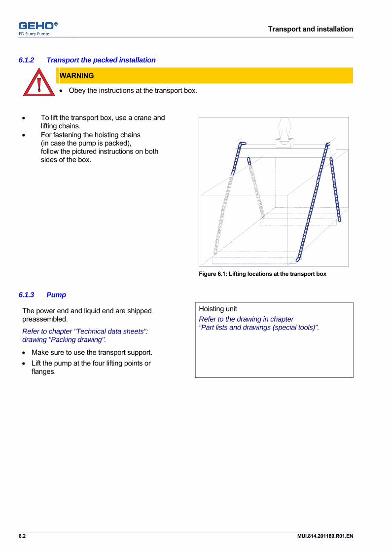
6.1.2 Transport the packed installation Pos: 12.2.3.2 /GEHO/Transport and installation/Transport and lifting/Transport/Transport box @ 0\mod_1137408396926_31.doc @ 1182
WARNING
• Obey the instructions at the transport box.
• To lift the transport box, use a crane and lifting chains.
• For fastening the hoisting chains (in case the pump is packed), follow the pictured instructions on both sides of the box.
Figure 6.1: Lifting locations at the transport box
Pos: 12.2.4 /GEHO/Heading/H3/#.#.# Pump @ 0\mod_1137414488876_31.doc @ 1207
6.1.3 Pump Pos: 12.2.5 /GEHO/Transport and installation/Transport and lifting/Lifting locations/TZPM/Standard, pump+liq.end, refer to special tools @ 1\mod_1173178868349_31.doc @ 12620
The power end and liquid end are shipped preassembled.
Refer to chapter "Technical data sheets": drawing "Packing drawing".
• Make sure to use the transport support. • Lift the pump at the four lifting points or
flanges.
Hoisting unit Refer to the drawing in chapter “Part lists and drawings (special tools)”.
Pos: 12.2.6 /--- Page break --- @ 0\mod_1136278659331_0.doc @ 766

Transport and installation
MUI.814.201189.R01.EN 6.3
Pos: 12.2.7.1 /GEHO/Heading/H3/#.#.# Drive unit @ 0\mod_1136807338183_31.doc @ 987
6.1.4 Drive unit Pos: 12.2.7.2 /GEHO/Transport and installation/Transport and lifting/Lifting locations/Drive Unit/Drive unit-no-motor+gearbox+1hoistspreaders$01 @ 2\mod_1188825775979_31.doc @ 15122
6.1.5 Drive unit frame 1 Use a standard hoist spreader (A) to avoid
damage (not in the scope of supply). 2 Lift the unit at the 4 frame lifting points (B). If this kind of hoist spreader is not available, then:1 Dis-assemble the gearbox from the frame. 2 Hoist separately the gearbox and the frame at
their hoisting points.
C
B1B2
B4B3
A
Figure 6.2: Lifting locations at the drive unit frame
Pos: 12.2.8.1 /GEHO/Heading/H3/#.#.# Smaller parts @ 0\mod_1136807299788_31.doc @ 985
6.1.6 Smaller parts Pos: 12.2.8.2 /GEHO/Transport and installation/Transport and lifting/Lifting locations/Smaller parts @ 0\mod_1136809345700_31.doc @ 995
• Lift the smaller parts at the desired lifting locations. • Use lifting straps or a forklift. Error! Unknown switch argument. Pos: 12.2.9 /GEHO/General/Attention, Warning and Note/Warning - Lifting locations @ 0\mod_1137404858107_31.doc @ 1159
WARNING
• Refer to chapter "Special tools", the drawing “Lifting tools” for the exact lifting locations,
lifting values and restrictions. Pos: 12.3 /--- Page break --- @ 0\mod_1136278659331_0.doc @ 766
Transport and installation
6.4 MUI.814.201189.R01.EN
Pos: 12.4 /GEHO/Heading/H2/#.# Installation @ 0\mod_1136888682286_31.doc @ 1015
6.2 Installation Pos: 12.5.1 /GEHO/Heading/H3/#.#.# Foundation @ 0\mod_1136888827835_31.doc @ 1021
6.2.1 Foundation Pos: 12.5.2 /GEHO/Transport and installation/Installation/Foundation/Foundation bolt schematics @ 0\mod_1136891863740_31.doc @ 1025
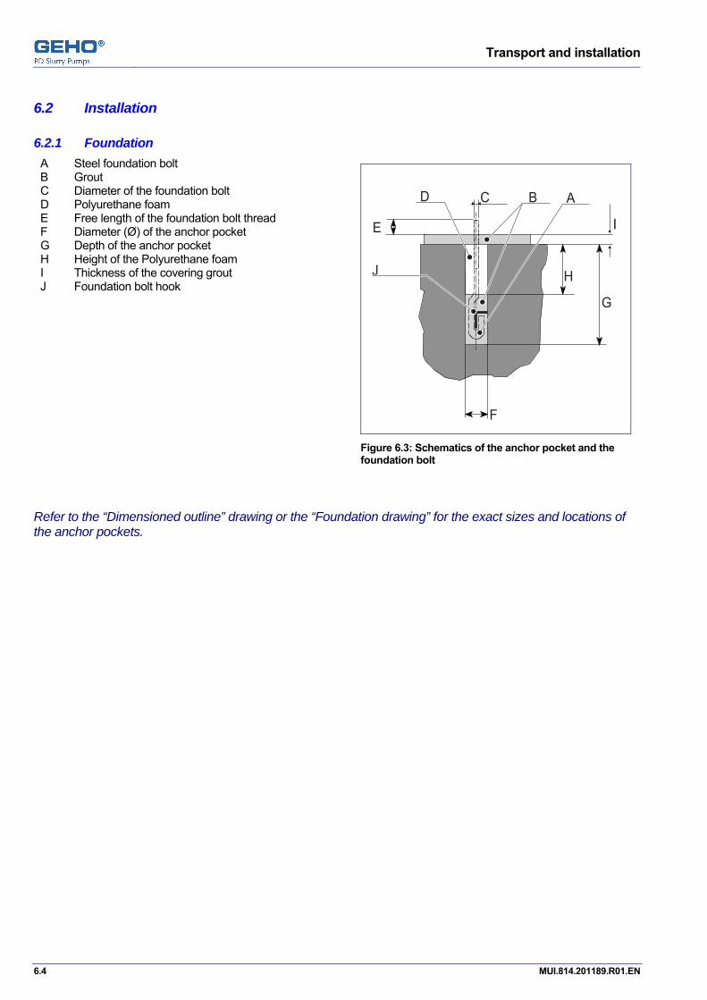
A Steel foundation bolt B Grout C Diameter of the foundation bolt D Polyurethane foam E Free length of the foundation bolt thread F Diameter (Ø) of the anchor pocket G Depth of the anchor pocket H Height of the Polyurethane foam I Thickness of the covering grout J Foundation bolt hook
F
B A
G
H
IE
CD
J
Figure 6.3: Schematics of the anchor pocket and the foundation bolt
Pos: 12.5.3 /GEHO/Transport and installation/Installation/Foundation/Refer to "Dimensioned outline" drawing or "Foundation drawing" @ 0\mod_1136893431935_31.doc @ 1027
Refer to the “Dimensioned outline” drawing or the “Foundation drawing” for the exact sizes and locations of the anchor pockets. Pos: 12.5.4 /--- Page break --- @ 0\mod_1136278659331_0.doc @ 766

Transport and installation
MUI.814.201189.R01.EN 6.5
Pos: 12.5.5.1 /GEHO/Heading/H4/#.#.# Mount and level the pump @ 0\mod_1136965605812_31.doc @ 1041
6.2.2 Mount and level the pump Pos: 12.5.5.2 /GEHO/Transport and installation/Installation/Foundation/Mount and level/TZPM/Level - TZPM @ 0\mod_1137418638092_31.doc @ 1214
1 Check the foundation according to the "DIMENSIONED OUTLINE DRAWING" and/or the "FOUNDATION DRAWING".
2 Place steel blocks next to each anchor pocket. Use steel blocks with a thickness of 50 mm.
3 Level the steel blocks in a range of 1 mm. 4 Lift the pump. Use a crane. 5 Put the thread of the foundation bolts into the borings at the pump. 6 Put the nuts to the foundation bolts. 7 Lower the pump 8 Put the pump to the steel blocks. 9 Make sure that the foundation bolts fit into the anchor pockets. 10 Hook the foundation bolts in their dedicated position. 11 Tighten the nuts at the foundation bolts by hand. 12 Place exactly below all leveling bolts of the pump a plane steel block.
Use steel blocks with a thickness of about 40 mm. ATTENTION Avoid that any pollution does enter the inside of the pump, during the time that a below mentioned frame cover are removed from the pump.
13 Remove 1 cover of a piston cover and crosshead chamber. See the figure beside.
14 Place a spirit level (C) on the machined face in direction A-A.
15 Level the pump. Keep a tolerance of 0.5 mm/m. Use the leveling bolts.
16 Place a spirit level (C) on the machined face in direction B-B.
17 Level the pump. Keep a tolerance of 0.5 mm/m. Use the leveling bolts.
18 Mount back the frame cover, immediately after the leveling of the pump.
C
AA
B
B
Figure 6.4: Spirit level positions
19 Fill up the space between the pump and the steel blocks with metal packing shims. 20 Check that the base frame rests on the packing shims. 21 Loosen and remove all leveling bolts. 22 Fill the lower section of all anchor pockets,
to fix all foundation bolts in their position. Refer to the drawing of the anchor pocket.
23 Fill the upper section of all anchor pockets with polyurethane foam. Refer to the drawing of the anchor pocket.
24 Put on a top layer of grout. 25 When the grout is hardened, then tighten all nuts at the foundation bolts.
Make sure to use the correct torques. Refer to chapter "Tightening torques". 26 Make sure to use the correct torques. Refer to chapter "Tightening torques". Pos: 12.6 /--- Page break --- @ 0\mod_1136278659331_0.doc @ 766

Transport and installation
6.6 MUI.814.201189.R01.EN
Pos: 12.7.1 /GEHO/Heading/H3/#.#.# Drive unit @ 0\mod_1136807338183_31.doc @ 987
6.2.3 Drive unit Pos: 12.7.2 /GEHO/Transport and installation/Installation/Drive unit/Gearbox/Overview @ 0\mod_1136990349612_31.doc @ 1091
A Coupling gearbox / pump shaft B Gearbox C Coupling gearbox / motor D Motor E Motor tighten screws F Leveling bolts G Hole for foundation bolts H Metal packing shim I Adjustment screws J Lifting eye K Safety guard
Figure 6.5: Drive unit with gearbox overview
Pos: 12.7.3 /GEHO/Transport and installation/Installation/Drive unit/Gearbox/Mount @ 0\mod_1136903066579_31.doc @ 1039
6.2.3.1 Mount the drive unit 1 Place steel blocks (E) next to each anchor
pocket. 2 Lift the drive unit.
Use a crane. 3 Put the thread of the foundation bolts (C)
into the holes at the pump drive base frame (D).
4 Put the nuts to the foundation bolts. 5 Lower the pump drive base frame 6 Put the pump drive unit to the steel
blocks (E). 7 Make sure that the foundation bolts (C) fit
into the anchor pockets. 8 Hook the foundation bolts in their
dedicated position. 9 Center the gearbox output shaft (A) with
the pump shaft (B). 10 Level the pump drive unit.
Use the leveling bolts at the base frame (D).
C D E
AB
Figure 6.6: Mount the drive unit
Pos: 12.7.4 /--- Page break --- @ 0\mod_1136278659331_0.doc @ 766
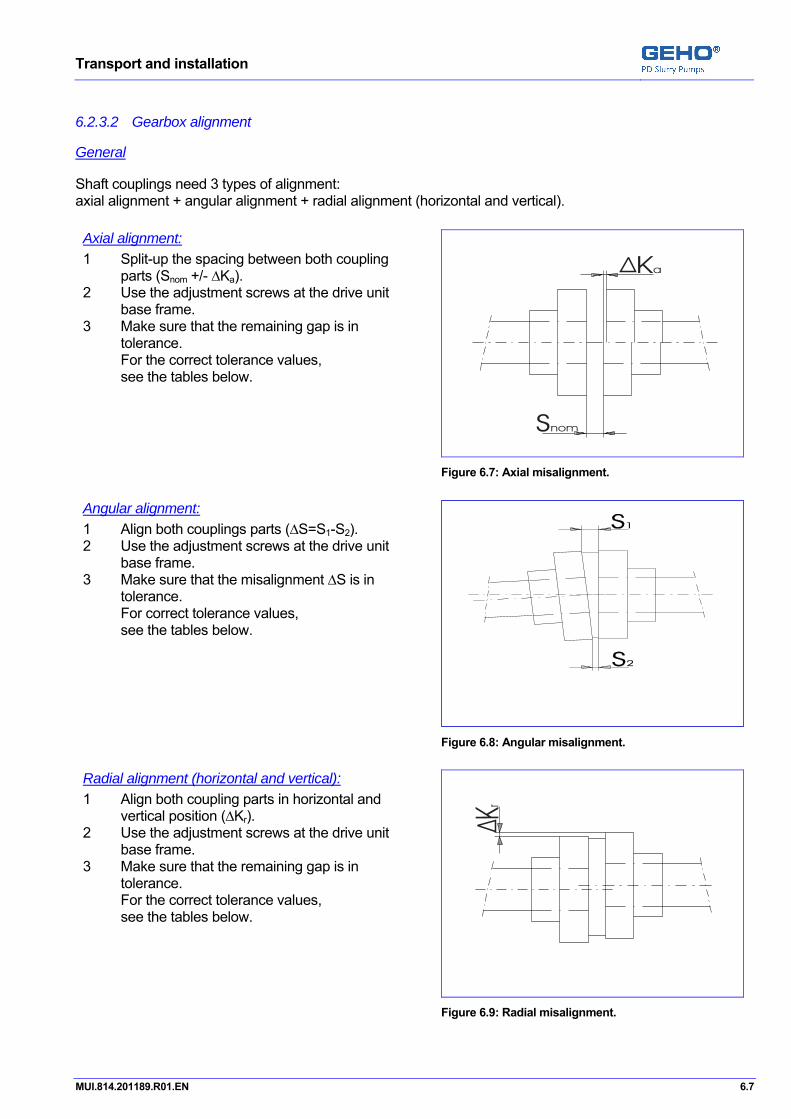
Transport and installation
MUI.814.201189.R01.EN 6.7
Pos: 12.7.5 /GEHO/Heading/H4/Gearbox alignment @ 0\mod_1136967931366_31.doc @ 1045
6.2.3.2 Gearbox alignment Pos: 12.7.6 /GEHO/Heading/H5/General @ 0\mod_1136967977522_31.doc @ 1047
General Pos: 12.7.7 /GEHO/Transport and installation/Installation/Drive unit/General/Introduction @ 0\mod_1136968488297_31.doc @ 1053
Shaft couplings need 3 types of alignment: axial alignment + angular alignment + radial alignment (horizontal and vertical). Pos: 12.7.8 /GEHO/Transport and installation/Installation/Drive unit/General/Alignment - Axial @ 0\mod_1136969611422_31.doc @ 1055
Axial alignment: 1 Split-up the spacing between both coupling
parts (Snom +/- ∆Ka). 2 Use the adjustment screws at the drive unit
base frame. 3 Make sure that the remaining gap is in
tolerance. For the correct tolerance values, see the tables below.
Figure 6.7: Axial misalignment.
Pos: 12.7.9 /GEHO/Transport and installation/Installation/Drive unit/General/Alignment - Angular @ 0\mod_1136976079252_31.doc @ 1059
Angular alignment: 1 Align both couplings parts (∆S=S1-S2). 2 Use the adjustment screws at the drive unit
base frame. 3 Make sure that the misalignment ∆S is in
tolerance. For correct tolerance values, see the tables below.
Figure 6.8: Angular misalignment.
Pos: 12.7.10 /GEHO/Transport and installation/Installation/Drive unit/General/Alignment - Radial @ 0\mod_1136978990869_31.doc @ 1063
Radial alignment (horizontal and vertical): 1 Align both coupling parts in horizontal and
vertical position (∆Kr). 2 Use the adjustment screws at the drive unit
base frame. 3 Make sure that the remaining gap is in
tolerance. For the correct tolerance values, see the tables below.
Figure 6.9: Radial misalignment.
Pos: 12.7.11 /--- Page break --- @ 0\mod_1136278659331_0.doc @ 766
Transport and installation
6.8 MUI.814.201189.R01.EN
Pos: 12.7.12 /GEHO/Heading/H5/H4_Gearbox - pump shaft - Pre-alignment @ 0\mod_1136968077676_31.doc @ 1049
6.2.3.3 Pre-alignment of the gearbox and the pump shaft Pos: 12.7.13 /GEHO/General/Attention, Warning and Note/Note - Refer alignment information @ 0\mod_1136979880428_31.doc @ 1067
NOTE
Refer to chapter “Catalogue information”, "Drive unit" for details about > safety instructions, > coupling alignment methods and mis-alignment limits, > coupling assembly and maintenance.
Pos: 12.7.14 /GEHO/Transport and installation/Installation/Drive unit/Gearbox - Pumpshaft/Pre alignment procedure @ 0\mod_1136983950690_31.doc @ 1069
Align the gearbox to the pump shaft: 1 Refer to the table below for the alignment tolerance values. 2 Adjust the spacing between both coupling parts (Snom ± ∆Ka). 3 Align both coupling parts in horizontal and vertical direction (∆Kr). 4 Align the angle between the gearbox shaft and motor shaft (∆S). Attach the unit base frame to the foundation: 5 Fill the space between the steel blocks and the drive unit base frame with metal packing shims. 6 Loosen the leveling bolts. 7 Fix all foundation bolts in position. 8 Wait until the grout is hardened. 9 Tighten all foundation bolts with the correct tightening torques. Pos: 12.7.15 /GEHO/Transport and installation/Installation/Drive unit/Gearbox - Pumpshaft/Alignment tolerances/ZAPEX ZWN 545, no internal gear @ 1\mod_1173171186122_31.doc @ 12612
Alignment tolerance values for FLENDER ZAPEX ZWN type couplings:
Size [mm]
Pump direct driven Snom [mm]
Axial mis-alignment ∆Ka [mm]
Angular mis-alignment(2) ∆S=S1-S2 [mm]
Radial mis-alignment ∆Kr [mm]
Combined mis-alignment ∆S + ∆Kr [mm]
545 16 -0 / +2.0 0.38 ≤ ∆S ≤ 0.76 0.05° ≤ angle ≤ 0.10°
≤ 0.71 ≤ 0.71 Pos: 12.7.16 /GEHO/General/Attention, Warning and Note/Note (2) Alignment limits @ 0\mod_1136975969234_31.doc @ 1057
NOTE
To improve lifetime performance of the teeth of the coupling parts, an intentional angular mis-alignment (in a static condition) is recommended. (2) Minimum limits (lower value) of mis-alignment values are based upon minimum 0.05° angle. Maximum limits (higher value) of mis-alignment values are based upon maximum 0.10° angle. In operation a maximum of 10 fold is allowed (= maximum 1.00° angle of all mis-allignments together, per one coupling half).
Pos: 12.7.17 /GEHO/Heading/H5/H4_Gearbox - pump shaft - Final alignment @ 0\mod_1136984882160_31.doc @ 1074
6.2.3.4 Final alignment of the gearbox and the pump shaft Pos: 12.7.18 /GEHO/Transport and installation/Installation/Drive unit/Gearbox - Pumpshaft/ZAPEX ZWN Final alignment procedure @ 0\mod_1136984368161_31.doc @ 1072
CAUTION
Premature wear and resulting damage to the coupling can be caused by: > incorrect alignment of the coupling, > incorrect assembly of the coupling, > incorrect sealing or lubricant of the coupling, > incorrect greasing of the DUO sealing rings.
Re-aligning: 1 Re-align the gearbox to the pump shaft as described before. Attaching the gearbox: 2 Fill the space between the gearbox and the base frame.
Use metal packing shims or modify the installed spacer plates. 3 Tighten the gearbox to the drive unit base frame.
Coupling assembly: Refer to "Catalogue information", "Drive unit", "Coupling" for manufacturer information about > the physical shape of the coupling,

Transport and installation
MUI.814.201189.R01.EN 6.9
> the assembly of the coupling, > how to make the coupling oil leak proof, > filling the coupling with oil.
Refer to "Utility consumption list" for details about oil type and oil quantity.
4 Grease the surface of the DUO-rings (B)
and the groves in cover rings (A). Recommended lubrication grease: > Shell Alvania RL3. > Mobil Mobilux EP3.
5 Mount the DUO sealing rings (B) proper in the cover rings (A).
6 Insert generously grease in the ring-shaped space (C) between the sealing lips of the DUO-rings (B). To seal properly during operation, the DUO-ring sealing lips have to float on a generous grease film. Recommended lubrication grease: > Shell Alvania RL3. > Mobil Mobilux EP3.
7 Clean and dry the sealing surfaces (D) of the coupling parts.
8 Cover the sealing surfaces (D) of the coupling parts with a sealing compound. Recommended sealing compound: Flange Sealant Loctite 5922.
9 Position carefully the cover rings (A) with the DUO-rings (B) on the pre-greased coupling shafts. Assure right position of the DUO-rings sealing lips.
10 Assemble the coupling covers (E) and cover rings (A) together.
F E E FD D D
ABC
ABC
Figure 6.10: Coupling assembly and sealing
Coupling oil filling: 11 Rotate the coupling, until the oil screw
plugs are in the position, as shown in the figure (D1 = filling plug, D2 = ventilation plug, D3 = drain plug).
12 Remove the two top screw plugs (D1+D2). 13 Measure the correct oil/grease quantity
with a measuring beaker. 14 Fill the coupling with the recommended oil. 15 Screw in all screw plugs (D) with
fitted/integrated sealing rings. 16 Check that the coupling cover does not
leak, by rotating the shaft. Safety protection: 17 Mount the safety guard.
D1 = Filling plug
60°
D3 = Drain plug
D2 = Ventilation plug
60°
30 °
Figure 6.11: Coupling oil filling
Pos: 12.7.19 /--- Page break --- @ 0\mod_1136278659331_0.doc @ 766

Transport and installation
6.10 MUI.814.201189.R01.EN
Pos: 12.7.20 /GEHO/Heading/H5/H4_Motor - Gearbox @ 0\mod_1136968126046_31.doc @ 1051
6.2.3.5 Motor and gearbox Pos: 12.7.21 /GEHO/General/Attention, Warning and Note/Note - Refer alignment information @ 0\mod_1136979880428_31.doc @ 1067
NOTE
Refer to chapter “Catalogue information”, "Drive unit" for details about > safety instructions, > coupling alignment methods and mis-alignment limits, > coupling assembly and maintenance.
Pos: 12.7.22 /GEHO/Transport and installation/Installation/Drive unit/Motor - Gearbox/Alignment procedure @ 0\mod_1136985418902_31.doc @ 1081
Align the motor to the gearbox: 1 Refer to the table below for the alignment tolerance values. 2 Adjust the spacing between both coupling parts (Snom ± ∆Ka). 3 Align both coupling parts in horizontal and vertical direction (∆Kr). 4 Align the angle between the gearbox shaft and motor shaft (∆S). Attach the motor on the unit base frame: 5 Modify the metal packing shims if necessary. 6 Tighten the motor to the drive unit base frame. 7 Month the safety guards. Pos: 12.7.23 /GEHO/Transport and installation/Installation/Drive unit/Motor - Gearbox/Alignment tolerances/RUPEX RWN 450 @ 5\mod_1226504188561_31.doc @ 43653
Alignment tolerance values for couplings:
Size [mm]
Axial distance Snom [mm]
Axial mis-alignment ∆Ka [mm]
Angular mis-alignment ∆S=S1-S2 [mm]
Radial mis-alignment ∆Kr [mm]
FLENDER RUPEX RWN 450
5.5 ± 1.5 ≤ 0.10 ≤ 0.10 Pos: 12.8 /--- Page break --- @ 0\mod_1136278659331_0.doc @ 766
Transport and installation
MUI.814.201189.R01.EN 6.11
Pos: 12.9 /GEHO/Transport and installation/Installation/Nitrogen filling/Safety regulations for nitrogen @ 0\mod_1156234263710_31.doc @ 5734
6.2.4 Safety regulations and instructions for nitrogen
DANGER
SAFETY Before using a nitrogen bottle equipment: • Working with a nitrogen bottle equipment is only allowed to authorized and instructed
workers. • Inform about all local legal and insurance policy regulations and safety instructions. • Inform about all local labor conditions about working with a nitrogen bottle equipment. • Strictly obey to those regulations and safety instructions. Refer to the safety instructions of the nitrogen bottle supplier, about how to handle nitrogen, its equipment, and what to do in emergency cases.
DANGER
NITROGEN Leaking nitrogen (N2) causes lack of oxygen: • Prevent breathing in nitrogen. • Be aware of the risk of suffocation, caused by to much nitrogen in the air. • Prevent nitrogen escaping from the equipment into the working environment. • Assure in small rooms good ventilation, because of risks of nitrogen leakage. • Assure free escape routes, because of risks of nitrogen leakage.
DANGER
NITROGEN EQUIPMENT INSTRUCTIONS • The supply of a nitrogen bottle is not in the scope of Weir Minerals. Refer to "Catalogue information" for instructions and information of the manufacturer about safe and proper user of the nitrogen bottle and nitrogen charging equipment.
If the nitrogen charging equipment is not in the scope of Weir Minerals, then refer to instructions and information of the manufacturer about safe and proper use.
• Make sure that the maximum pressure in the nitrogen bottle does not exceed the maximum permitted pressure of the pressure regulator.
• Make sure that the equipment is in good condition. Pos: 12.10 /--- Page break --- @ 0\mod_1136278659331_0.doc @ 766

Transport and installation
6.12 MUI.814.201189.R01.EN
Pos: 12.11 /GEHO/Heading/H5/H5-Suction line @ 4\mod_1213287469058_31.doc @ 33145
Suction line Pos: 12.12 /GEHO/Heading/H3/#.#.# Pre-charging the suction pulsation dampener, set-point instructions @ 1\mod_1173202054425_31.doc @ 12636
6.2.5 Pre-charging the suction pulsation dampener, set-point instructions Pos: 12.13 /GEHO/Transport and installation/Installation/Nitrogen filling/Pre-charging/Suction pulsation dampener pre-charge @ 1\mod_1173084644396_31.doc @ 12574 discharge
6.2.5.1 Suction pulsation dampener pre-charge set-point instructions
The suction pulsation dampener minimizes the pressure variations in the suction line. This achieves a constant flow in the suction line. A rubber diaphragm separates the pulsation dampener into 2 sections:
• The slurry section. • The nitrogen section, pre-charged with nitrogen.
6.2.5.2 Suction pulsation dampener pre-charge set-point instructions
DANGER
Safety limits: To prevent over-stressing the dampener system and the diaphragm: • NEVER pre-charge the pulsation dampener with more then the dampener system,
maximum pressure. The maximum pressure is indicated on the pulsation dampener identification plate.
• NEVER pre-charge the pulsation dampener with more then the maximum pressure for the diaphragm limit. The diaphragm limit pressure is indicated in the "Technical data".
ATTENTION
Functional limits: To prevent dampener diaphragm damage during pressure still-stand of the pump and hammering of the diaphragm against the bottom of the dampener: • NEVER pre-charge the pulsation dampener with more then 80% of the maximum pump
suction pressure. To prevent hammering of the diaphragm against the top of the dampener: • NEVER let the pre-charge pressure drop below 30% of the maximum pump suction
pressure.
Excessive pressure pulsations and heavy vibrations are caused by insufficient pre-charge pressure.
ATTENTION The pre-charge pressure may change due to temperature influence: • Temperature fluctuation of the slurry. • Temperature differences between the slurry and the environment. These effects require re-adjustment of the pre-charge pressure.

Transport and installation
MUI.814.201189.R01.EN 6.13
Refer to the "Instrument and equipment list" for details about the "suction pulsation dampener".
Refer to the "Instrument and equipment list" for the dampener pre-charge "set-point" recommendation for installation, to start with.
Refer to the “Installation and maintenance instructions”, before working on a GEHO pulsation damper.
The pre-charge pressure is application dependent. Operating conditions Recommended pre-charge set-point
Percentage of maximum suction pressure
Result
80% = maximum pre-charge limit, but NEVER more than the diaphragm limit, as indicated in the "Instrument and equipment list"
to protect the diaphragm and dampener
constant suction pressure 60% to 65% optimal operation
widely varying suction pressure 30% to 35% optimal operation
30% = minimum pre-charge limit to protect the diaphragm and dampener
Pos: 12.14 /--- Page break --- @ 0\mod_1136278659331_0.doc @ 766

Transport and installation
6.14 MUI.814.201189.R01.EN
Pos: 12.15 /GEHO/Heading/H5/H5-Suction line @ 4\mod_1213287469058_31.doc @ 33145
Suction line Pos: 12.16 /GEHO/Transport and installation/Installation/Nitrogen filling/Pre-charging/Nitrogen bottle: charging equipment+procedure @ 3\mod_1201872347283_31.doc @ 26031
6.2.5.3 Nitrogen bottle with charging equipment, filler valve mounted on the damper
DANGER
Usually not in the scope of supply of Weir Minerals are nitrogen filling equipment parts (nitrogen bottle, pressure reducer, safety relieve valve, charging unit and hose). • Check that all used parts are in accordance with local standards and safety regulations.
A Nitrogen (N2) bottle B Nitrogen bottle main valve C Pressure reducer: C1 Pressure gauge, indicating the bottle pressure C2 Pressure gauge, indicating the actual filling
pressure in the hose C3 Pressure reducer valve
D Safety relieve valve,
to protect the pulsation dampener against pressure overload. Relieve pressure depends on the maximum allowed pressure of the pulsation dampener.
E Charging hose for high pressure nitrogen charging
F Nitrogen charging unit F1 Charging unit main valve F2 Pressure drain valve G Dampener filler valve
(at the top of the dampener or at the P&I-skid panel)
H Pressure gauge (at the top of the dampener or at the P&I-skid panel), indicating: • During pump operation: the pump discharge pressure. • During filling: the actual nitrogen charging pressure.
I Pulsation dampener
A B C1 C2 C3 D E F1 F2 G H I
Figure 6.12: Nitrogen bottle with dampener charging equipment
If the dampener filler valve is mounted on a skid, then refer for the position of the parts to the drawing of the filler equipment in chapter "Appendix: Parts -lists and drawings (special tools).

Transport and installation
MUI.814.201189.R01.EN 6.15
6.2.5.4 Filling preparation 1 If there is a pressure gauge mounted on the charging unit (F),
then check the pressure rating of this gauge. If the pressure rating of the gauge is lower than the maximum allowed pressure at the dampener, then remove this gauge and close the connection opening with a suitable high pressure plug.
2 Connect the charging unit (F) at the filler valve (G). 3 Close the main valve (F1) and the drain valve (F2) at the nitrogen charging unit (F). 4 Close the pressure reducer valve (C3). 5 Connect the pressure reducer (C+D) to the nitrogen bottle (A+B). 6 Open slowly the nitrogen bottle valve (B).
• Check at the gauge (C1) the bottle pressure, it has to be more than the recommended dampener pre-charge pressure. • Check that no nitrogen is leaking at the hose connection.
7 Connect the hose (E) to the pressure reducer (C+D). 8 Flush the hose clean.
• Open for a second and than immediately close the pressure reducer valve (C3). 9 Connect the hose (E) to the charging unit (F).
6.2.5.5 Nitrogen pre-charge filling 1 Open the filler valve (G) and the main valve (F1),
so the hose is filled with nitrogen from the dampener. 2 Check at the gauge (C2) and the gauge (H) the pre-charge pressure of the dampener.
The pressure has to be the same at both gauges. 3 Open in many small steps the pressure reducer valve (C3),
until the recommended pre-charge pressure is reached at the gauge (C2) and the gauge (H).
DANGER
• Prevent fast filling, for it causes icing at the valves and the hose.
4 When the recommended pre-charge pressure is reached, then: 5 Close the nitrogen bottle valve (B), so the nitrogen supply is closed. 6 Close the filler valve (G) and the main valve (F1), so the pulsation dampener is isolated. 7 To release the nitrogen pressure in the hose:
Open slowly the drain valve (F2), nitrogen will escape, until the pressure at the gauge (C2) is zero. 8 Remove the hose (E) from the pressure reducer (C+D) and the charging unit (F). 9 If the charging unit (F) gets removed, then recap the connection opening at the dampener. 10 Check at the joints at the dampener and at the filling connection of the dampener (without cap),
that there is no nitrogen leakage, by using a leak detector spray or similar. Pos: 12.17 /--- Page break --- @ 0\mod_1136278659331_0.doc @ 766
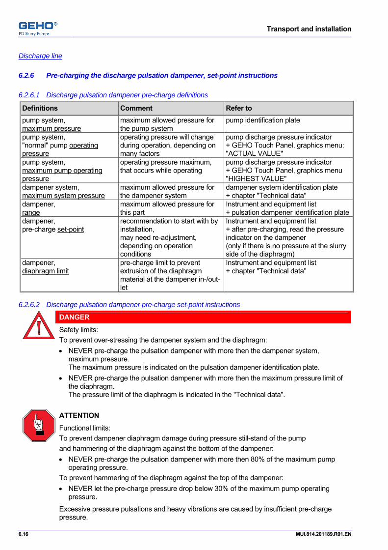
Transport and installation
6.16 MUI.814.201189.R01.EN
Pos: 12.18 /GEHO/Heading/H5/H5-Discharge line @ 4\mod_1213287464731_31.doc @ 33137
Discharge line Pos: 12.19 /GEHO/Heading/H3/#.#.# Pre-charging the discharge pulsation dampener, set-point instructions @ 1\mod_1173202078632_31.doc @ 12640
6.2.6 Pre-charging the discharge pulsation dampener, set-point instructions Pos: 12.20 /GEHO/Transport and installation/Installation/Nitrogen filling/Pre-charging/Discharge pulsation dampener pre-charge @ 0\mod_1156257465577_31.doc @ 5764 discharge
6.2.6.1 Discharge pulsation dampener pre-charge definitions
Definitions Comment Refer to pump system, maximum pressure
maximum allowed pressure for the pump system
pump identification plate
pump system, "normal" pump operating pressure
operating pressure will change during operation, depending on many factors
pump discharge pressure indicator + GEHO Touch Panel, graphics menu: "ACTUAL VALUE"
pump system, maximum pump operating pressure
operating pressure maximum, that occurs while operating
pump discharge pressure indicator + GEHO Touch Panel, graphics menu "HIGHEST VALUE"
dampener system, maximum system pressure
maximum allowed pressure for the dampener system
dampener system identification plate + chapter "Technical data"
dampener, range
maximum allowed pressure for this part
Instrument and equipment list + pulsation dampener identification plate
dampener, pre-charge set-point
recommendation to start with by installation, may need re-adjustment, depending on operation conditions
Instrument and equipment list + after pre-charging, read the pressure indicator on the dampener (only if there is no pressure at the slurry side of the diaphragm)
dampener, diaphragm limit
pre-charge limit to prevent extrusion of the diaphragm material at the dampener in-/out-let
Instrument and equipment list + chapter "Technical data"
6.2.6.2 Discharge pulsation dampener pre-charge set-point instructions
DANGER
Safety limits: To prevent over-stressing the dampener system and the diaphragm: • NEVER pre-charge the pulsation dampener with more then the dampener system,
maximum pressure. The maximum pressure is indicated on the pulsation dampener identification plate.
• NEVER pre-charge the pulsation dampener with more then the maximum pressure limit of the diaphragm. The pressure limit of the diaphragm is indicated in the "Technical data".
ATTENTION
Functional limits: To prevent dampener diaphragm damage during pressure still-stand of the pump and hammering of the diaphragm against the bottom of the dampener: • NEVER pre-charge the pulsation dampener with more then 80% of the maximum pump
operating pressure. To prevent hammering of the diaphragm against the top of the dampener: • NEVER let the pre-charge pressure drop below 30% of the maximum pump operating
pressure.
Excessive pressure pulsations and heavy vibrations are caused by insufficient pre-charge pressure.

Transport and installation
MUI.814.201189.R01.EN 6.17
ATTENTION The pre-charge pressure may change due to temperature influence: • Temperature fluctuation of the slurry. • Temperature differences between the slurry and the environment. These effects require re-adjustment of the pre-charge pressure.
The pre-charge pressure is application dependent. Refer to the "Instrument and equipment list" for details about the "discharge pulsation dampener".
Refer to the "Instrument and equipment list" for the dampener pre-charge "set-point" recommendation for installation, to start with.
Operating conditions Recommended pre-charge set-pointPercentage of operating pressure
Result
80% = maximum pre-charge limit, but NEVER more than the diaphragm limit, as indicated in the "Instrument and equipment list".
to protect the diaphragm and the dampener
constant operating pressure 60% to 65% optimal operation
widely varying operating pressure 30% to 35% optimal operation
30% = minimum pre-charge limit to protect the diaphragm and dampener
NOTE
High dampener pre-charge pressure (related to the operating pressure) gives the best dampening results.
If the operating pressure decreases, then this can cause wear and damage to the diaphragm and metal insert, by continuously hammering at the dampener bottom.
If working with relatively constant pump pressures, then the GEHO diaphragm pulsation dampeners are to be charged at 60%-65% of the pumps normal operating pressure (see GEHO Touch Panel, menu Graphics: "ACTUAL VALUE").
If operating the pump with widely varying pressures, then it can be necessary to pre-charge the pulsation dampener at 30%-35% of the pumps maximum operating pressure (see GEHO Touch Panel, menu Graphics: "HIGHEST VALUE").
Pos: 12.21 /--- Page break --- @ 0\mod_1136278659331_0.doc @ 766

Transport and installation
6.18 MUI.814.201189.R01.EN
Pos: 12.22 /GEHO/Heading/H5/H5-Discharge line @ 4\mod_1213287464731_31.doc @ 33137
Discharge line Pos: 12.23 /GEHO/Transport and installation/Installation/Nitrogen filling/Pre-charging/Dampener-Nitrogen bottle+charging equipment on P&I skid @ 2\mod_1183369041811_31.doc @ 14352
6.2.6.3 Nitrogen bottle with charging equipment
DANGER
Usually not in the scope of supply of Weir Minerals are nitrogen filling equipment parts (nitrogen bottle, pressure reducer, safety valve and drain valve). • Check that they are in accordance with local standards and safety regulations.
A Nitrogen bottle B Nitrogen bottle valve R Safety relieve,
to protect the pulsation dampener against overload. Relieve pressure depends on the maximum allowed pressure of the pulsation dampener.
S Drain valve Nitrogen pressure regulator unit: C Pressure regulator C1 Pressure gauge indicating the bottle pressure C2 Pressure gauge indicating the actual filling
pressure in the hose C3 Pressure reducer valve D High pressure hose Nitrogen filling device: E Pressure gauge pulsation dampener F Mounting block G Filling valve pulsation dampener H Connector of the nitrogen filling device I Fixed connection to pulsation dampener J Fixed connection to working pressure
transmitter N Pulsation dampener
N
I
A D
C
B
C2C1
C3
S
R
I
E
F
G
H
J
Figure 6.13: Pre-charging the pulsation dampener with the nitrogen filling device
Pos: 12.24 /GEHO/Transport and installation/Installation/Nitrogen filling/Pre-charging/Pulsation dampener pre-charging procedure using the nitrogen filling device on P&I skid @ 2\mod_1183376823646_31.doc @ 14362
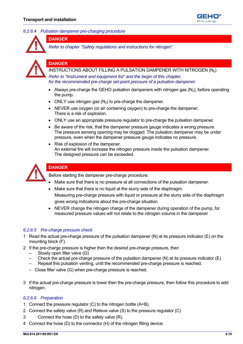
Transport and installation
MUI.814.201189.R01.EN 6.19
6.2.6.4 Pulsation dampener pre-charging procedure
DANGER
Refer to chapter "Safety regulations and instructions for nitrogen".
DANGER
INSTRUCTIONS ABOUT FILLING A PULSATION DAMPENER WITH NITROGEN (N2) Refer to "Instrument and equipment list" and the begin of this chapter, for the recommended pre-charge set-point pressure of a pulsation dampener.
• Always pre-charge the GEHO pulsation dampeners with nitrogen gas (N2), before operating the pump.
• ONLY use nitrogen gas (N2) to pre-charge the dampener. • NEVER use oxygen (or air containing oxygen) to pre-charge the dampener.
There is a risk of explosion. • ONLY use an appropriate pressure regulator to pre-charge the pulsation dampener. • Be aware of the risk, that the dampener pressure gauge indicates a wrong pressure.
The pressure sensing opening may be clogged. The pulsation dampener may be under pressure, even when the dampener pressure gauge indicates no pressure.
• Risk of explosion of the dampener. An external fire will increase the nitrogen pressure inside the pulsation dampener. The designed pressure can be exceeded.
DANGER
Before starting the dampener pre-charge procedure: • Make sure that there is no pressure at all connections of the pulsation dampener. • Make sure that there is no liquid at the slurry side of the diaphragm. Measuring pre-charge pressure with liquid or pressure at the slurry side of the diaphragm gives wrong indications about the pre-charge situation. • NEVER change the nitrogen charge of the dampener during operation of the pump, for
measured pressure values will not relate to the nitrogen volume in the dampener
6.2.6.5 Pre-charge pressure check 1 Read the actual pre-charge pressure of the pulsation dampener (N) at its pressure indicator (E) on the
mounting block (F). 2 If the pre-charge pressure is higher then the desired pre-charge pressure, then
– Slowly open filler valve (G) – Check the actual pre-charge pressure of the pulsation dampener (N) at its pressure indicator (E) – Repeat this pulsation venting, until the recommended pre-charge pressure is reached. – Close filler valve (G) when pre-charge pressure is reached.
3 If the actual pre-charge pressure is lower then the pre-charge pressure, then follow this procedure to add
nitrogen.
6.2.6.6 Preparation 1 Connect the pressure regulator (C) to the nitrogen bottle (A+B). 2 Connect the safety valve (R) and Relieve valve (S) to the pressure regulator (C) 3 Connect the hose (D) to the safety valve (R). 4 Connect the hose (D) to the connector (H) of the nitrogen filling device.
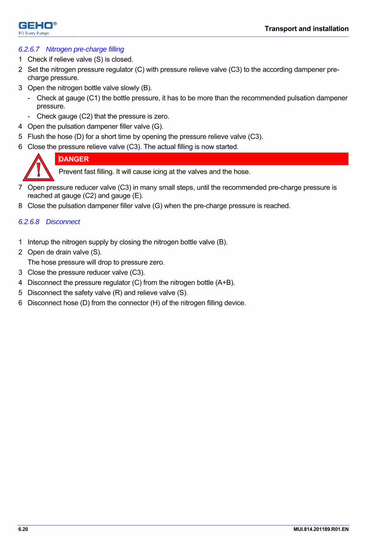
Transport and installation
6.20 MUI.814.201189.R01.EN
6.2.6.7 Nitrogen pre-charge filling 1 Check if relieve valve (S) is closed. 2 Set the nitrogen pressure regulator (C) with pressure relieve valve (C3) to the according dampener pre-
charge pressure. 3 Open the nitrogen bottle valve slowly (B).
- Check at gauge (C1) the bottle pressure, it has to be more than the recommended pulsation dampener pressure.
- Check gauge (C2) that the pressure is zero. 4 Open the pulsation dampener filler valve (G). 5 Flush the hose (D) for a short time by opening the pressure relieve valve (C3). 6 Close the pressure relieve valve (C3). The actual filling is now started.
DANGER
Prevent fast filling. It will cause icing at the valves and the hose.
7 Open pressure reducer valve (C3) in many small steps, until the recommended pre-charge pressure is reached at gauge (C2) and gauge (E).
8 Close the pulsation dampener filler valve (G) when the pre-charge pressure is reached.
6.2.6.8 Disconnect 1 Interup the nitrogen supply by closing the nitrogen bottle valve (B). 2 Open de drain valve (S). The hose pressure will drop to pressure zero. 3 Close the pressure reducer valve (C3). 4 Disconnect the pressure regulator (C) from the nitrogen bottle (A+B). 5 Disconnect the safety valve (R) and relieve valve (S). 6 Disconnect hose (D) from the connector (H) of the nitrogen filling device. Pos: 12.25 /--- Page break --- @ 0\mod_1136278659331_0.doc @ 766

Transport and installation
MUI.814.201189.R01.EN 6.21
Pos: 12.26 /GEHO/Heading/H3/#.#.# Pre-charging the accumulator with nitrogen @ 1\mod_1166006986593_31.doc @ 9291
6.2.7 Pre-charging an accumulator with nitrogen Pos: 12.27 /GEHO/Transport and installation/Installation/Nitrogen filling/Pre-charging/Nitrogen bottle+charging equipment+accumulator+safety valve @ 4\mod_1210236627950_31.doc @ 29246
6.2.7.1 Nitrogen bottle with charging equipment, accumulator
DANGER
Nitrogen bottle and pressure reducer are usually not in the scope of supply of Weir Minerals. Check that they are in accordance with local standards and safety regulations.
A Nitrogen (N2) bottle B Nitrogen bottle main manual valve C Pressure reducer: D Pressure gauge, indicating the bottle pressure E Pressure gauge, indicating the actual filling
pressure in the hose F Pressure reducer valve G Charging hose
for high pressure nitrogen charging H Charging unit: I Non-return valve
(prevents gas to flow out of the accumulator) J Shut-off-valve K Manual valve for pressure relief L Pressure gauge indicating the actual filling
pressure M Accumulator N 3/2 manual ball valve, with drain side to
release the pressure at the fluid side of the accumulator
O Safety relieve valve, to protect the accumulator against pressure overload. The relieve pressure depends on the maximum allowed pressure of the accumulator and the charging equipment.
A B C D E O F G H I J K L M N
Figure 6.14: Nitrogen bottle with charging equipment
Pos: 12.28 /--- Page break --- @ 0\mod_1136278659331_0.doc @ 766
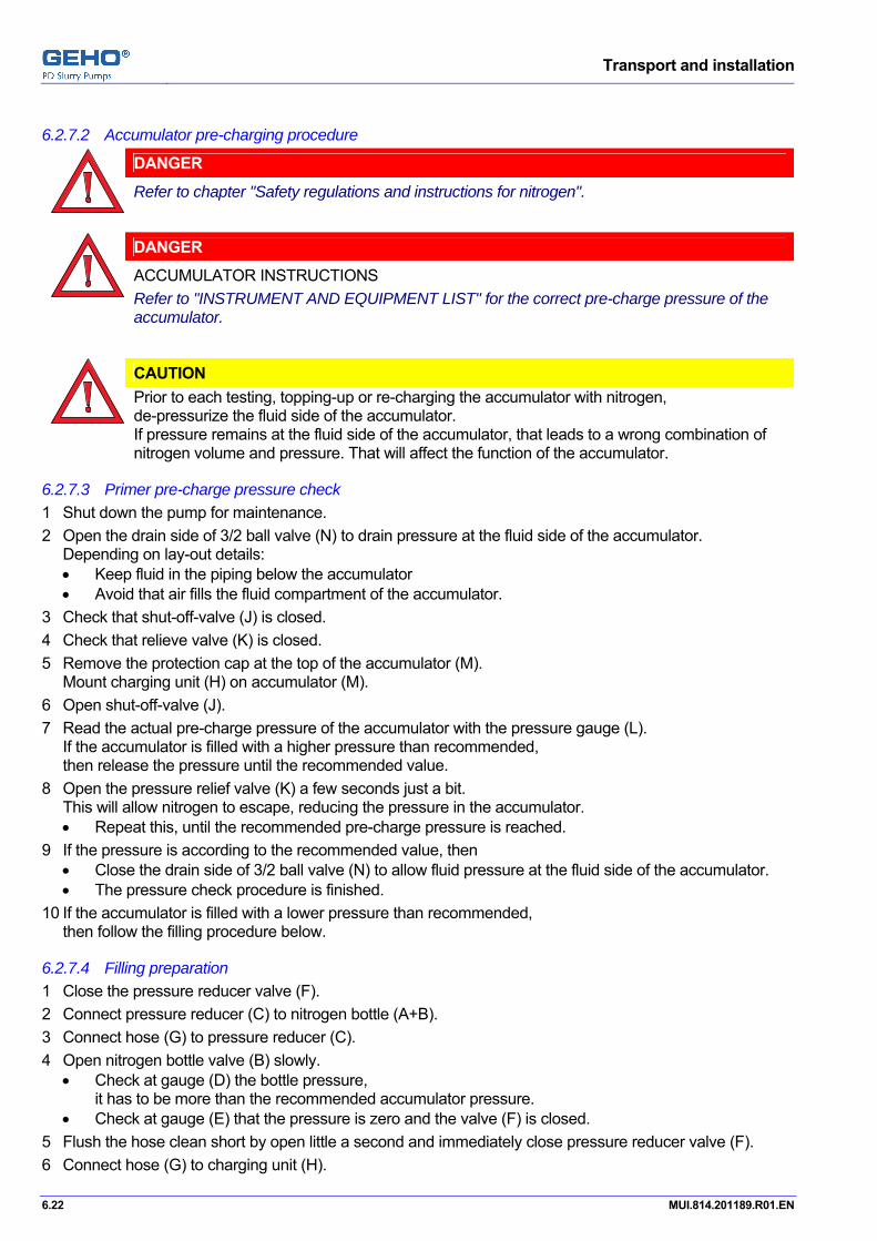
Transport and installation
6.22 MUI.814.201189.R01.EN
Pos: 12.29 /GEHO/Transport and installation/Installation/Nitrogen filling/Pre-charging/Accu-N2-pre-charging procedure with safety valve @ 1\mod_1169741590336_31.doc @ 12010
6.2.7.2 Accumulator pre-charging procedure
DANGER
Refer to chapter "Safety regulations and instructions for nitrogen".
DANGER
ACCUMULATOR INSTRUCTIONS Refer to "INSTRUMENT AND EQUIPMENT LIST" for the correct pre-charge pressure of the accumulator.
CAUTION
Prior to each testing, topping-up or re-charging the accumulator with nitrogen, de-pressurize the fluid side of the accumulator. If pressure remains at the fluid side of the accumulator, that leads to a wrong combination of nitrogen volume and pressure. That will affect the function of the accumulator.
6.2.7.3 Primer pre-charge pressure check 1 Shut down the pump for maintenance. 2 Open the drain side of 3/2 ball valve (N) to drain pressure at the fluid side of the accumulator.
Depending on lay-out details: • Keep fluid in the piping below the accumulator • Avoid that air fills the fluid compartment of the accumulator.
3 Check that shut-off-valve (J) is closed. 4 Check that relieve valve (K) is closed. 5 Remove the protection cap at the top of the accumulator (M).
Mount charging unit (H) on accumulator (M). 6 Open shut-off-valve (J). 7 Read the actual pre-charge pressure of the accumulator with the pressure gauge (L).
If the accumulator is filled with a higher pressure than recommended, then release the pressure until the recommended value.
8 Open the pressure relief valve (K) a few seconds just a bit. This will allow nitrogen to escape, reducing the pressure in the accumulator. • Repeat this, until the recommended pre-charge pressure is reached.
9 If the pressure is according to the recommended value, then • Close the drain side of 3/2 ball valve (N) to allow fluid pressure at the fluid side of the accumulator. • The pressure check procedure is finished.
10 If the accumulator is filled with a lower pressure than recommended, then follow the filling procedure below.
6.2.7.4 Filling preparation 1 Close the pressure reducer valve (F). 2 Connect pressure reducer (C) to nitrogen bottle (A+B). 3 Connect hose (G) to pressure reducer (C). 4 Open nitrogen bottle valve (B) slowly.
• Check at gauge (D) the bottle pressure, it has to be more than the recommended accumulator pressure. • Check at gauge (E) that the pressure is zero and the valve (F) is closed.
5 Flush the hose clean short by open little a second and immediately close pressure reducer valve (F). 6 Connect hose (G) to charging unit (H).
Transport and installation
MUI.814.201189.R01.EN 6.23
6.2.7.5 Nitrogen pre-charge filling 1 Open shut-off-valve (J). 2 Open pressure reducer valve (F) in many small steps until the recommended pre-charge pressure is
reached at gauge (E) and gauge (l).
DANGER
Prevent fast filling, it will cause icing at the valves and the hose.
3 When the recommended pre-charge pressure is reached, then: 4 Close nitrogen bottle valve (B), so the nitrogen supply is interrupted. 5 Close pressure reducer valve (F). 6 Close shut-off-valve (J), so the accumulator is isolated. 7 To release the nitrogen pressure in the hose:
Open pressure relief valve (K). • Check at gauge (L) that the pressure is zero. • Check at gauge (E) that the pressure is zero.
6.2.7.6 Disconnect the nitrogen supply line 1 Check, that nitrogen bottle valve (B) is closed. 2 Disconnect pressure regulator (C) from nitrogen bottle (A+B). 3 Disconnect hose (G) pressure regulator (C+O). 4 Disconnect hose (G) from charging unit (H).
6.2.7.7 Return to operation. 1 If charging unit (H) stays at the accumulator, then:
• Leave shut-off-valve (J) shut. • Read the fluid pressure only at the pressure gauge at the fluid side, not at gauge (I). • Check for leakages on valve (J) and its connection to the accumulator, using a leak detector spray.
2 If removing charging unit (H), then: • Disconnect charging unit (H) from accumulator (M). • Check for leakages on the accumulator top, using a leak detector spray. • Mount the protection cap at the top of the accumulator (M).
3 Close the drain side of 3/2 ball valve (N) to allow fluid pressure at the fluid side of the accumulator. Pos: 13 /--- Section break - Odd page --- @ 0\mod_1136277036628_0.doc @ 765

Transport and installation
6.24 MUI.814.201189.R01.EN

Operation, Start-up + Start + Stop procedures
MUI.814.201189.R01.EN 7.1
Pos: 14.1 /GEHO/Heading/H1/#. Operation, Start-up + Start + Stop procedures @ 0\mod_1136455316013_31.doc @ 933
7 Operation, Start-up + Start + Stop procedures Pos: 14.2 /GEHO/Heading/H2/## Start-up checklist, GEHO + VFD main power switch OFF @ 2\mod_1173875659029_31.doc @ 12732 Preparation
7.1 Start-up, working with the GEHO + VFD main power switch OFF ATTENTION • Use this procedure, to make the pump system ready for operation (at first at installation, and after working on the pump). • Secure the main power switches against "unwanted switch-on".
VFD = "Variable Frequency converter Device " that regulates the speed of the main motor.
Pos: 14.3 /GEHO/Start and Stop/Common/Warning - Heavy parts - Use hoisting eye @ 1\mod_1165935566336_31.doc @ 9221
WARNING
The heavy parts of the pumps are provided with a hoisting eye or have the possibility to install a hoisting eye for transportation purposes. • Always transport these parts by using these hoisting eyes.
Pos: 14.4 /GEHO/Heading/H3/#.#.# Initial lubrication filling @ 1\mod_1171376311244_31.doc @ 12412
7.1.1 Initial lubrication filling Pos: 14.5 /GEHO/Start and Stop/Common/Lubrication - Initial @ 1\mod_1165995657192_31.doc @ 9251
If applicable, then check and perform an initial lubrication filling of the following parts.
7.1.1.1 Gear box (if applicable): 1 Check the oil level in the gearbox. 2 If necessary, then add or drain oil until the right level is reached. Refer to chapter "Appendix: Catalogue information" for details about the procedure. Refer to the "UTILITY CONSUMPTION LIST" for details about the oil type and oil quantity.
7.1.1.2 Tooth coupling between gearbox and pump shaft (if applicable): Refer to the chapter "Installation", "Drive unit" for details. Refer to chapter "Appendix: Catalogue information" for details about the procedure. Refer to the "UTILITY CONSUMPTION LIST" for details about the oil type and oil quantity.
7.1.1.3 Power end:
Working with the main power switch OFF: 1 Clean the power end side, if necessary. 2 Open the main covers. 3 Open the side covers. 4 Clean the crosshead liners. 5 Fill the oil sump with oil.
Use a combined oil-filter/oil-water-separator to clean the oil.
Refer to the "UTILITY CONSUMPTION LIST" for details about the oil type and oil quantity.
6 Check the oil level gauge. At initial filling or re-filling, the oil level should be near level (B).
7 Close all covers.
B
A
Figure 7.1: Correct oil filling level at the oil level gauge

Operation, Start-up + Start + Stop procedures
7.2 MUI.814.201189.R01.EN
Working with the main power switch ON at the GEHO control box: 8 Check the direction of rotation of the lubrication pump. Refer to the chapter "Start-up, electrical check".
9 Start the lubrication pump. 10 Check the oil level gauge.
After 5 minutes, oil is distributed in the lubrication system and the oil level should be about half height at the oil level gauge, near level (A). If necessary, then fill additional oil until level (A).
11 Check the lubrication system.
Continue working with the main power switch OFF at the GEHO control box. Pos: 14.6 /GEHO/Heading/H3/#.#.# Propelling liquid @ 1\mod_1166007118791_31.doc @ 9297
7.1.2 Propelling liquid Pos: 14.7 /GEHO/Start and Stop/Propelling liquid - Initial @ 1\mod_1165936154067_31.doc @ 9227
Refer to the "UTILITY CONSUMPTION LIST" for details about the oil type and oil quantity.
1 Open the propelling liquid tank cover. 2 Clean the propelling liquid tank. 3 Fill the propelling liquid tank to the upper liquid level. 4 Check the liquid level at the liquid level gauge. 5 Close the propelling liquid tank cover. Pos: 14.8 /GEHO/Heading/H3/#.#.# Air supply unit @ 0\mod_1146140424938_31.doc @ 3465
7.1.3 Air supply unit Pos: 14.9 /GEHO/Start and Stop/Common/Air supply check @ 1\mod_1165998689770_31.doc @ 9254
ATTENTION • Air pressure must ALWAYS be available, even when the slurry pump is not in operation. Without air pressure, the pump system will stop immediately by an pressure alarm or soon by an electric operation control alarm. Because the air valves are spring-opened, air pressure is necessary to avoid liquid-loss or liquid-overfilling in the propelling liquid chambers.
• Check that pressure and quality and quantity of the compressed air supply meet the required standards. Refer to "Technical data", "UTILITY CONSUMPTION LIST" for details about the compressed air supply.
• Check that the air supply line is flushed clean, before connecting it to the pump system. • Connect the compressed air supply. Pos: 14.10 /--- Page break --- @ 0\mod_1136278659331_0.doc @ 766

Operation, Start-up + Start + Stop procedures
MUI.814.201189.R01.EN 7.3
Pos: 14.11 /GEHO/Heading/H3/#.#.# Pre-charging a pulsation dampener with nitrogen @ 0\mod_1156314333839_31.doc @ 5777
7.1.4 Procedure pre-charging a pulsation dampener with nitrogen Pos: 14.12 /GEHO/Start and Stop/Common/Pre-charge pulsation dampener, refer to installation @ 1\mod_1169653974927_31.doc @ 11992
Refer to "Transport and installation", "Pre-charging the pulsation dampener" for the procedure.
• Check that the pulsation dampener is pre-charged with nitrogen, according to the procedure. Pos: 14.13 /GEHO/Heading/H3/#.#.# Pre-charging the accumulator with nitrogen @ 1\mod_1166006986593_31.doc @ 9291
7.1.5 Pre-charging an accumulator with nitrogen Pos: 14.14 /GEHO/Start and Stop/Common/Pre-charge accumulator-gas @ 1\mod_1170093129172_31.doc @ 12048
The accumulator of the propelling liquid system must be pre-charged with gas. Refer to the "INSTRUMENT LIST" for the correct pre-charge pressure.
Refer to the "UTILITY CONSUMPTION LIST" for the gas quality.
Refer to the chapter "Installation" for the pre-charging procedure and set-point.
Refer to the chapter "Transport and installation", "Pre-charging the accumulator" for the procedure. Pos: 14.15 /GEHO/Heading/H2/## Start-up checklist, GEHO main power switch=ON, VFD=OFF @ 2\mod_1173875689375_31.doc @ 12737 eparation
7.2 Start-up checklist, working with the GEHO main power switch ON DANGER
• Make sure that the power of the main motor and its VFD is switched OFF. • Secure the main power switch of the main motor and its VFD against "unwanted switch-
on". VFD = "Variable Frequency converter Device " that regulates the speed of the main motor.
ATTENTION • Use this procedure, to make the pump system ready for operation (at first at installation, and after working on the pump).
Pos: 14.16 /GEHO/Heading/H3/#.#.# Main power switch @ 1\mod_1166007056288_31.doc @ 9294
7.2.1 Main power switch Pos: 14.17 /GEHO/Start and Stop/Common/Start-up, main power supply @ 1\mod_1170157413431_31.doc @ 12075
From this step on, to proceed the "Start, preparation check list", electric main power supply is needed only at the GEHO Pump Control System and its GEHO Touch Panel. Pos: 14.18 /GEHO/Start and Stop/Common/Start-up, main power switch @ 1\mod_1165998832165_31.doc @ 9257
DANGER
While working on the pump, it is not permitted to start the pump. • Secure the main power switch against "unwanted switch-on",
until the pump system is safe to run. • DO NOT switch on the main power switch, until the pump system is safe to run. • Set the main power switch to 0-position (OFF) only in case of working during maintenance
or service.
1 Check that the pump EMERGENCY STOP SYSTEM is operational. 2 Check, that the pump system is safe to switch on and run. 3 Switch the main power switch on the control panel to 1-position (ON). Pos: 14.19 /GEHO/Heading/H3/#.#.# Start-up, electrical check @ 1\mod_1170159443932_31.doc @ 12080
7.2.2 Start-up, electrical check Pos: 14.20 /GEHO/Start and Stop/Common/Start-up, electric check @ 1\mod_1170159737562_31.doc @ 12084
1 Ask an authorized electrician to check that the auxiliary electric motors turn in the direction, as indicated on the motor cover or on the pump power end.
2 If a motor turns in the wrong direction, then change the electrical connections. Pos: 14.21 /GEHO/Start and Stop/Common/Start-up, power end oil check @ 2\mod_1173876188272_31.doc @ 12742
7.2.3 Initial power end oil check 1 Check the oil level at the power end. Refer to chapter "Initial lubrication filling". Pos: 14.22 /--- Page break --- @ 0\mod_1136278659331_0.doc @ 766

Operation, Start-up + Start + Stop procedures
7.4 MUI.814.201189.R01.EN
Pos: 14.23 /GEHO/Heading/H2/#.# Start-up, priming procedure @ 2\mod_1175856788072_31.doc @ 13082 eparation
7.3 Start-up, priming procedure ATTENTION • Use this procedure, to make the pump system ready for operation (at first at installation, and after working on the pump).
Pos: 14.24 /GEHO/Heading/H3/#.#.# Priming the slurry section @ 1\mod_1166006925672_31.doc @ 9288
7.3.1 Priming the slurry section Pos: 14.25 /GEHO/Start and Stop/TZPM/Priming the slurry section @ 1\mod_1166001286915_31.doc @ 9269
7.3.1.1 Targets of priming the slurry section: 1. De-aeration of the slurry section, by filling water via a flushing water connection (D) in the suction line and
draining the water through valve (B) in the discharge line. 2. De-aeration of each propelling liquid chamber through valves (E) and (G) and (F). 3. To obtain a controlled starting position for filling all propelling liquid chambers, the flush water pressure will
force the diaphragm against the rear wall of the diaphragm housing, where position marker (M) meets switch (ZSL).
ATTENTION
Refer to "Utility consumption list" for the flush water quality and quantity and pressure.
7.3.1.2 Procedure filling the slurry section with flush water and de-aeration
Figure 7.2: Filling and de-aerating the slurry section
1 Start up the air unit (needed for proper function of the propelling liquid system).
Closing the slurry section: 2 Close the main valve (C) in the suction line. 3 Close the main valve (A) in the discharge line.
De-aerating the slurry section: 4 Open valve (D) of the flush water connection to the suction line. Refer to "Utility consumption list" for the flush water quality and quantity and pressure.
5 Open the drain valve (B) in the discharge line. Wait until flush water discharges from the drain valve (B).

Operation, Start-up + Start + Stop procedures
MUI.814.201189.R01.EN 7.5
6 Close the drain valve (B).
De-aerating the propelling liquid chambers and positioning the diaphragms in starting position: 7 Partly open drain valve (B) in the discharge line, to maintain in the slurry section a pressure, as
specified in the "Utility consumption list". > The pressure of the flush water must be high enough to force the propelling liquid to escape through non-return-valve (F).
8 Open the vent valves (E) of all propelling liquid chambers (located on the rear side top of the diaphragm housing). The flush water pressure moves all diaphragms in the priming start position (ZSL). Position marker (M) of each diaphragm rod meets switch (ZSL) and at the GEHO touch panel its light will light on.
9 Check at the GEHO touch panel, that the lights of switch (ZSL) of all pistons light on. 10 Continue with the next chapter, to prime the propelling liquid section. 11 Continue with the next chapter, to prime the propelling liquid section. Pos: 14.26 /--- Page break --- @ 0\mod_1136278659331_0.doc @ 766

Operation, Start-up + Start + Stop procedures
7.6 MUI.814.201189.R01.EN
Pos: 14.27 /GEHO/Heading/H3/#.#.# Priming the propelling liquid section @ 2\mod_1175857268341_31.doc @ 13087
7.3.2 Priming the propelling liquid section Pos: 14.28 /GEHO/Start and Stop/TZPM/Priming the propelling liquid section @ 1\mod_1166001870053_31.doc @ 9272
ATTENTION
Refer to "Utility consumption list" for the flush water quality and quantity and pressure.
Figure 7.3: Schematics of the TZPM propelling liquid section
De-aeration of the propelling liquid section: 1 Refer to the previous chapter to fill the slurry section with flush water and to move each diaphragm with
rod indicator (M) in its priming start position (ZSL). 2 Open the flush water connection (D) in the suction line. 3 Partly open the drain valve (B) in the discharge line, to maintain in the slurry section a pressure, as
specified in the "Utility consumption list". > A diaphragm needs pressure at both sides, to move properly. > The pressure of the flush water must be high enough to force the propelling liquid to escape through non-return-valve (F).
4 Start at the GEHO touch panel the propelling liquid pump. 5 Open the vent valves (E) in the propelling liquid section of all diaphragms. 6 Open the vent valve (G) to de-aerate the common line at safety relief valve (H) of the propelling liquid
system. 7 Push at the GEHO touch panel the button "MAIN SUPPLY VALVE", to open the main supply filling
valve (K) for 15 minutes. Refer to the "P&I Diagram" for details about the propelling liquid automatic control system. Refer to the GEHO touch panel and its manual for details about how operation conditions are displayed at the panel.
8 Close the vent valves (E) and (G), if the propelling liquid, that discharges through valve (F), contains no air bubbles.
9 If necessary, then repeat the steps 7 and 8 until all vent valves (E) of the diaphragms are closed. 10 After de-aeration, as long as a filling valve is open,
> propelling liquid will be filled into the pump chambers; > the diaphragms will leave the ZSL start position; > until the monitoring rods of the diaphragms de-activate the ZSL indicators; > the corresponding filling valves will close, the filling will stop; > at the GEHO touch panel the corresponding diaphragm position light (ZSL) will turn off.
11 If necessary, then repeat step 7 until at the GEHO touch panel all position lights of all diaphragms are off.

Operation, Start-up + Start + Stop procedures
MUI.814.201189.R01.EN 7.7
Positioning of the diaphragms in relation to the pistons:
ATTENTION Avoid that the pump rotates without lubrication. 12 Start the lubrication pump. 13 Check that the lubrication system delivers the oil quantity.
14 Rotate the pump crankshaft manually.
DANGER
• Make sure that the power of the drive motor is switched off.
Refer for details to the chapter "Manual rotation of the pump".
15 If at the GEHO touch panel one of the lights of switch (ZSH) or (ZSL) of the diaphragm position is lit, then stop rotation of the pump. > If indicator (M) meets switch (ZSL), so related switch light is lit, then the propelling liquid system will fill propelling liquid, until the indicator light is off. > If indicator (M) meets switch (ZSH), so related switch light is lit, then the propelling liquid automatic control system will drain propelling liquid, until the switch light is off.
16 Wait until this switch light is off. 17 Repeat steps 10 to 12 until no switch lights light up during rotation of the pump. 18 Turn the pump crankshaft another 2 turns, to check that no switch lights light up.
So all chambers are filled properly with propelling liquid and piston rod indicator (M) of the diaphragm moves properly between switch (ZSL) and switch (ZSH).
Arranging PRE-START of the pump 19 Close the drain valve (B) in the discharge line. 20 Close the flush water valve (D) of the flushing water connection in the suction line. 21 Stop the flush water supply. 22 Open the main valve (C) in the suction line. 23 Open the main valve (A) in the discharge line. Pos: 14.29 /--- Page break --- @ 0\mod_1136278659331_0.doc @ 766

Operation, Start-up + Start + Stop procedures
7.8 MUI.814.201189.R01.EN
Pos: 14.30 /GEHO/Heading/H2/#.# Operating touch panel and control system @ 1\mod_1169830993137_31.doc @ 12026
7.4 Operating the GEHO Touch Panel + GEHO Pump Control System Pos: 14.31 /GEHO/Start and Stop/Common/Operating touch panel LOCAL+REMOTE_R01 @ 1\mod_1169830665787_31.doc @ 12021
Refer to chapter "Technical data", "TYPICAL MANUAL OF THE GEHO TOUCH PANEL" for operating the GEHO Touch Panel.
Refer to chapter "Technical data", "DESCRIPTION OF THE PUMP CONTROL SYSTEM" for operating the GEHO Pump Control System.
7.4.1 Pump operation by local control at the GEHO Touch Panel The pump can be operated at the GEHO Touch Panel in a "stand alone" mode. The procedures in this manual cover the operation of the pump at the GEHO Touch Panel in its "stand alone" LOCAL mode.
7.4.1.1 Selection LOCAL-REMOTE at the GEHO Touch Panel
Check at the GEHO Touch Panel which actual operation mode is active: ■ LOCAL = local operation mode at the GEHO Touch Panel. ■ REMOTE = remote operation mode at a remote control device.
How to switch from local control (= LOC.) to remote control (= REM.) and back: • Push at the GEHO Touch Panel the field button LOC.REM. to switch from local control mode to remote
control mode and back.
7.4.2 Pump operation by remote control, supplied by others The GEHO Touch Panel control box has connections for remote control options.
WARNING
Remote control is usually not in the scope of supply of Weir Minerals and has to be provided by the customer. Refer to the user manual and safety instructions of the supplier of the remote control. Refer for details of the remote control options at the GEHO to "DESCRIPTION OF THE PUMP CONTROL SYSTEM" and "TYPICAL MANUAL OF THE GEHO TOUCH PANEL".
Selection LOCAL-REMOTE at the remote control device Refer to the user manual and safety instructions of the supplier of the remote control.
Pump operation at the remote control device Refer to the user manual and safety instructions of the supplier of the remote control.
Pos: 14.32 /--- Page break --- @ 0\mod_1136278659331_0.doc @ 766
Operation, Start-up + Start + Stop procedures
MUI.814.201189.R01.EN 7.9
Pos: 14.33 /GEHO/Heading/H2/#.# Start procedures @ 1\mod_1165935124304_31.doc @ 9209
7.5 Start procedures Pos: 14.34 /GEHO/Start and Stop/Common/START + Pre-start procedure_R02 @ 1\mod_1170848561800_31.doc @ 12151
7.5.1 Operation definitions Main motor RAMP-UP and RAMP-DOWN procedure at the VFD The speed of the electric main motor is controlled by a "Variable Frequency converter Device" (= VFD). At this VFD the minimum and the maximum speed of the main motor is locked in its pre-settings. These pre-settings can not be overruled at the GEHO Touch Panel or at a remote control device. If the VFD is not in the scope of supply of Weir Minerals, than the supplier has to assure the correct settings at the VFD.
• The "MAXIMUM SPEED LIMITATION" is part of the "Intended use" specification of the pump, to protect the main motor and the transmission parts and the pump against overload.
Refer for details to chapter "Technical data" and to the "GEHO pump identification plate" at the pump.
• The "MINIMUM SPEED LIMITATION" is NOT part of the "Intended use" specification of the pump, it is a recommendation to avoid pump speeds below this level.
This "MINIMUM SPEED LIMITATION" is part of the RAMP-UP and RAMP-DOWN procedure at the VFD.
How to operate the main motor RAMP-UP and RAMP-DOWN procedure at the GEHO Touch Panel: • Push the START button = the VFD performs the VFD RAMP-UP procedure,
to start the motor from STOP to the "MINIMUM SPEED LIMITATION". • Push the STOP button = the VFD performs the VFD RAMP-DOWN procedure,
to stop the motor from the "MINIMUM SPEED LIMITATION" to STOP.
ATTENTION The VFD performs the RAMP-UP and RAMP-DOWN procedures independently. These procedures can only be operated by EMERGENCY STOP or START or STOP commands, these procedures can not be influenced by other operation means.
ACTUAL SPEED at the GEHO Touch Panel The ACTUAL SPEED displayed at the GEHO Touch Panel gives the real speed of the pump (SPM = "Strokes Per Minute" = revolutions of the pump crank shaft).
SPEED-SETPOINT signal The SPEED-SETPOINT displayed at the GEHO Touch Panel indicates the desired speed of the main motor (so it can be different form the ACTUAL SPEED value). It can be set with the display buttons UP, DOWN and ZERO at the GEHO Touch Panel.
ATTENTION
The VFD will ignore: > a SPEED SETPOINT higher then the "MAXIMUM SPEED LIMITATION" set at the VDF, > a SPEED SETPOINT lower then the "MINIMUM SPEED LIMITATION" set at the VDF.
ZERO button at the GEHO Touch Panel • If the SPEED-SETPOINT at the GEHO Touch Panel is set to zero,
and the "MINIMUM SPEED LIMITATION" at the VFD is also set to zero, then the motor and the pump remain in a "stand-by idle status". (="0 SPM" at the GEHO Touch Panel = zero "Strokes Per Minute" = zero revolutions per minute of the pump crank shaft.)

Operation, Start-up + Start + Stop procedures
7.10 MUI.814.201189.R01.EN
7.5.2 PRE-START check list
DANGER
If the pump is operated, then the operator has to assure: 1 that the pump can run safely. 2 that the pump can deliver its flow safely. 3 that the pump will not run dry. • NEVER start the main motor, if one of the checks below fails.
Control systems: 1 Check the air supply and the air pressure. Refer to "UTILITY CONSUMPTION LIST" for details about quality and quantity and pressure.
2 Check the pre-charge pressure of the diaphragm pulsation dampeners. Propelling liquid section: 3 Check that the propelling liquid sections are filled. 4 Check that the propelling liquid sections are de-aerated. 5 Check that the propelling liquid de-aeration valves are closed. Slurry section at the pump: 6 Check that the slurry end is filled and de-aerated. Slurry lines of the pump system: 7 Check that all slurry line flushing valves are closed. 8 Check that all slurry line drain valves are closed. 9 Check that the slurry line main suction valve is open. 10 Check that the slurry line main discharge valve is open.
7.5.3 PRE-START, working with the GEHO and VFD main power switch ON 1 Check that the pump EMERGENCY STOP SYSTEM is operational. 2 Check that the main power switch of the GEHO pump system is switched ON. 3 Switch ON the main power switches of the VFD (Variable Frequency Drive) and the main motor.
Operation, Start-up + Start + Stop procedures
MUI.814.201189.R01.EN 7.11
7.5.4 PRE-START procedure - if LOCAL operated Use this procedure only, if the pump system is ready to operate. 1 Push the START/STOP button at the GEHO Touch Panel. 2 Push the PRE-START button at the GEHO Touch Panel.
The electrical PRE-START procedure performs: 2.1 Start of all auxiliary systems. 2.2 Check of the electrical PRE-START conditions.
The main motor can only start, if all pre-conditions are fulfilled. Refer for details to the electrical "LOGIC DIAGRAM" and "DESCRIPTION OF THE PUMP CONTROL SYSTEM".
2.3 During the PRE-START procedure the COMMON ALARM lamp flashes. 2.4 If the PRE-START procedure is finished successfully and the pump is ready to run, then
> the COMMON ALARM lamp stops flashing, > "PUMP READY TO RUN" is displayed at the GEHO Touch Panel. Go to the START procedure.
2.5 If the PRE-START procedure fails for the pump is not ready to run, then > the COMMON ALARM lamp keeps flashing, > the concerned alarms are displayed at the panel. Check the reasons for the alarms and solve the causes. Repeat this PRE-START procedure.
7.5.5 PRE-START procedure - if REMOTE operated Refer to the user manual and safety instructions of the supplier of the remote control.
During REMOTE operation, the GEHO Touch Panel displays: ■ REMOTE = remote operation mode at a remote control device.

Operation, Start-up + Start + Stop procedures
7.12 MUI.814.201189.R01.EN
7.5.6 START procedure - if LOCAL operated 1 Check the SPEED-SETPOINT at the GEHO Touch Panel.
Push the button ANALOG VALUES to check the SPEED SETPOINT. 2 Change the SPEED SETPOINT value with the buttons UP and DOWN. 3 Push the START button at the GEHO Touch Panel. 4 The VFD starts the RAMP-UP procedure,
the main motor starts and runs up first phase to the value of the "MINIMUM SPEED LIMITATION" at the VFD, second phase to value of the SPEED-SETPOINT speed.
4.1 Push the button ANALOG VALUES to check the SPEED SETPOINT and the ACTUAL SPEED. 4.2 If at the VFD the "MINIMUM SPEED LIMITATION" is set to zero,
then the motor will only speed up by pushing the UP button. Changing the speed of the pump: 1 Change the SPEED SETPOINT:
Push the UP button or DOWN button at the GEHO Touch Panel. ATTENTION The VFD will ignore: > a SPEED SETPOINT higher then the "MAXIMUM SPEED LIMITATION" set at the VDF, > a SPEED SETPOINT lower then the "MINIMUM SPEED LIMITATION" set at the VDF.
2 Check that the ACTUAL SPEED follows the SPEED SETPOINT value. Pos: 14.35 /GEHO/Start and Stop/Common/START, remote control @ 1\mod_1170863453339_31.doc @ 12161
7.5.7 START procedure - if REMOTE operated
INFORMATION
If applicable, refer to the manual of the supplier of the remote control system.
Refer also to "DESCRIPTION OF THE PUMP CONTROL SYSTEM" in chapter "Technical data" for details about remote control. • Push the button LOC.REM. to switch from local control to remote control and back.
During REMOTE operation, the GEHO Touch Panel displays: ■ REMOTE = remote operation mode at a remote control device. The ACTUAL SPEED of the pump. Pos: 14.36 /--- Page break --- @ 0\mod_1136278659331_0.doc @ 766

Operation, Start-up + Start + Stop procedures
MUI.814.201189.R01.EN 7.13
Pos: 14.37 /GEHO/Heading/H2/#.# Stop procedures @ 1\mod_1165935157213_31.doc @ 9212
7.6 Stop procedures Pos: 14.38 /GEHO/Heading/H3/#.#.# Emergency stop @ 1\mod_1166006853944_31.doc @ 9285
7.6.1 Emergency stop procedure Pos: 14.39 /GEHO/Start and Stop/Common/Emergency stop @ 1\mod_1166005615179_31.doc @ 9281
CE conformity
DANGER
An emergency shut down button has to be present within a short distance from the pump.
DANGER
When failing to install and maintain the EMERGENCY STOP button equipment in accordance with this manual, then the installation is no longer in CE-conformity (as defined by the European "Directive on machinery 98/37/EC and 2006/42/EC") and thus results in: "... machinery must not be put into service until the final machinery into which it is to be incorporated has been declared in conformity with the provisions of this Directive ..."
Refer to chapter "Safety equipment" for details about requirements of the EMERGENCY STOP system.
EMERGENCY STOP signal In case of an EMERGENCY STOP:
DANGER
• The EMERGENCY STOP overrules all other operation options.
• The electrical supply of all pump auxiliary motors will shut-down immediately. • The VFD (="Variable Frequency converter Device") stops the main motor. Refer for details to the manual of the VFD system in "Appendix: Catalogue information".
• The pump system (motor + transmission + pump) will without power supply stop (coast to rest, wasting its dynamic energy).
• The pump control system (with the GEHO touch panel) remains operational, but as long as the EMERGENCY STOP status remains, all operation options of the motors are blocked.
DANGER
After an EMERGENCY STOP: • Refer to the manual of the EMERGENCY STOP system of the supplier of that system for
procedures how to handle an EMERGENCY STOP and how to start again. • Make sure, that the reason for the EMERGENCY STOP is attended and solved,
before starting the pump again. After an EMERGENCY STOP, the pump system is ready for a regular PRE-START procedure. Pos: 14.40 /--- Page break --- @ 0\mod_1136278659331_0.doc @ 766

Operation, Start-up + Start + Stop procedures
7.14 MUI.814.201189.R01.EN
Pos: 14.41 /GEHO/Start and Stop/Common/### STOP button procedure, if LOCAL operated @ 1\mod_1170094694626_31.doc @ 12064
7.6.2 STOP button procedure, if LOCAL operated
ATTENTION This STOP button procedure is preferred: • For longer operation interruptions, to switch off all auxiliary systems of the pump. • For a normal stop, that does not require a EMERGENCT STOP. If the pump is stopped with the STOP button, then start the pump with the PRE-START button, to start all auxiliary systems.
To stop the pump: 1 If the pump runs in the REMOTE mode,
to switch the control in the LOCAL mode, then push the LOCAL/REMOTE button at the GEHO touch panel.
2 Push the STOP/STOP button at the GEHO touch panel. 3 Push the STOP button at the GEHO touch panel.
The automatic STOP program contains: 3.1 The VFD stops the main motor with the RAMP-DOWN procedure. 3.2 All auxiliary systems will stop. Pos: 14.42 /GEHO/Start and Stop/Common/### STOP by remote control @ 1\mod_1170863607721_31.doc @ 12166
7.6.3 STOP by remote control
INFORMATION
If applicable, refer to the user manual and safety instructions of the supplier of the remote control.
• Push at the GEHO Touch Panel the button LOC.REM. to switch from LOCAL control to REMOTE control and back.
Refer also to "DESCRIPTION OF THE PUMP CONTROL SYSTEM" in chapter "Technical data" for details about remote control.
Pos: 14.43 /--- Page break --- @ 0\mod_1136278659331_0.doc @ 766
Operation, Start-up + Start + Stop procedures
MUI.814.201189.R01.EN 7.15
Pos: 14.44 /GEHO/Heading/H3/#.#.# STOP for flushing @ 1\mod_1170094128268_31.doc @ 12056
7.6.4 STOP for flushing procedure Pos: 14.45 /GEHO/Start and Stop/Flushing slurry section, general @ 1\mod_1169569488886_31.doc @ 11969
7.6.4.1 Flushing the slurry section, general recommendations
ATTENTION
• Flush the slurry section, if the pump may get out of operation for a longer time. If the pump system stops for a longer period, then: – the slurry may get clogged,
so starting up may need more time and energy and cause troubles. – the slurry may get acid,
so this may result to damage to the inner surfaces of the pump slurry section. The decision to flush depends on: – the quality of the slurry, – the period of still stand, – general experience and operating and precaution arguments.
The flushing connections are not in the scope of supply of this pump system. Refer to drawing 814.200000.04 "FLUSHING/FILLING/DRAIN CONNECTIONS" in chapter "Technical data" for details, how this may be arranged on the pump system. Pos: 14.46 /GEHO/Start and Stop/Common/STOP, flushing procedure @ 1\mod_1170094728267_31.doc @ 12072
7.6.4.2 Flushing the slurry section procedure 1 Keep the pump system running at minimum speed. 2 Flush the pump with clean water for at least 5 minutes. 3 Stop the pump at the GEHO touch panel. Refer for details to "DESCRIPTION OF THE PUMP CONTROL SYSTEM" and "TYPICAL MANUAL OF THE GEHO TOUCH PANEL".
The slurry section of the pump remains filled with clean flush water. At the end of the flushing procedure the pump is in the right position for starting.
ATTENTION
Keep the pump system in the ready-to-start modus: • DO NOT switch off the air pressure.
This prevents that the propelling liquid sections get discharged. • DO NOT switch off the electric power supply.
Pos: 14.47 /--- Page break --- @ 0\mod_1136278659331_0.doc @ 766
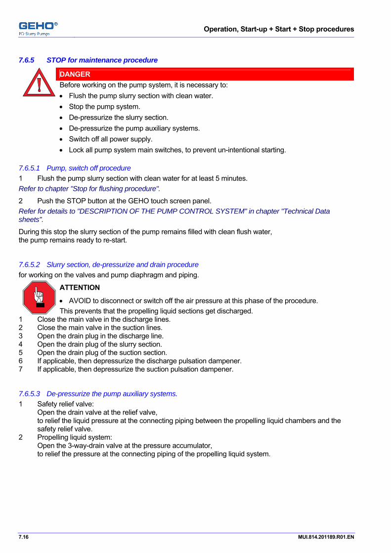
Operation, Start-up + Start + Stop procedures
7.16 MUI.814.201189.R01.EN
Pos: 14.48 /GEHO/Heading/H3/#.#.# STOP for maintenance procedure @ 1\mod_1170094160937_31.doc @ 12060
7.6.5 STOP for maintenance procedure Pos: 14.49 /GEHO/Start and Stop/Common/STOP, maintenance procedure @ 1\mod_1170094711772_31.doc @ 12068
DANGER
Before working on the pump system, it is necessary to: • Flush the pump slurry section with clean water. • Stop the pump system. • De-pressurize the slurry section. • De-pressurize the pump auxiliary systems. • Switch off all power supply. • Lock all pump system main switches, to prevent un-intentional starting.
7.6.5.1 Pump, switch off procedure 1 Flush the pump slurry section with clean water for at least 5 minutes. Refer to chapter "Stop for flushing procedure".
2 Push the STOP button at the GEHO touch screen panel. Refer for details to "DESCRIPTION OF THE PUMP CONTROL SYSTEM" in chapter "Technical Data sheets".
During this stop the slurry section of the pump remains filled with clean flush water, the pump remains ready to re-start.
7.6.5.2 Slurry section, de-pressurize and drain procedure for working on the valves and pump diaphragm and piping.
ATTENTION
• AVOID to disconnect or switch off the air pressure at this phase of the procedure. This prevents that the propelling liquid sections get discharged.
1 Close the main valve in the discharge lines. 2 Close the main valve in the suction lines. 3 Open the drain plug in the discharge line. 4 Open the drain plug of the slurry section. 5 Open the drain plug of the suction section. 6 If applicable, then depressurize the discharge pulsation dampener. 7 If applicable, then depressurize the suction pulsation dampener.
7.6.5.3 De-pressurize the pump auxiliary systems. 1 Safety relief valve:
Open the drain valve at the relief valve, to relief the liquid pressure at the connecting piping between the propelling liquid chambers and the safety relief valve.
2 Propelling liquid system: Open the 3-way-drain valve at the pressure accumulator, to relief the pressure at the connecting piping of the propelling liquid system.

Operation, Start-up + Start + Stop procedures
MUI.814.201189.R01.EN 7.17
7.6.5.4 Stop the air supply To disconnect or switch off the air pressure, obey the procedure below.
ATTENTION
• Stop the air only with this procedure. This procedure prevents that the propelling liquid sections get discharged.
De-pressurize the slurry suction line and slurry discharge line at the pump(s): 1 Close the main suction valve in the slurry line. 2 Close the main discharge valves in the slurry line. 3 Open the drain valve in the slurry discharge line. 4 Stop and dis-connect the air supply.
7.6.5.5 Switch off the electric main supply to all related parts
DANGER
1 Switch off all electric main switches for the pump system and the main motor and its
VFD. 2 Lock all electric main switches, to prevent un-intentional starting.
Operation, Start-up + Start + Stop procedures
7.18 MUI.814.201189.R01.EN
Pos: 15 /--- Section break - Odd page --- @ 0\mod_1136277036628_0.doc @ 765
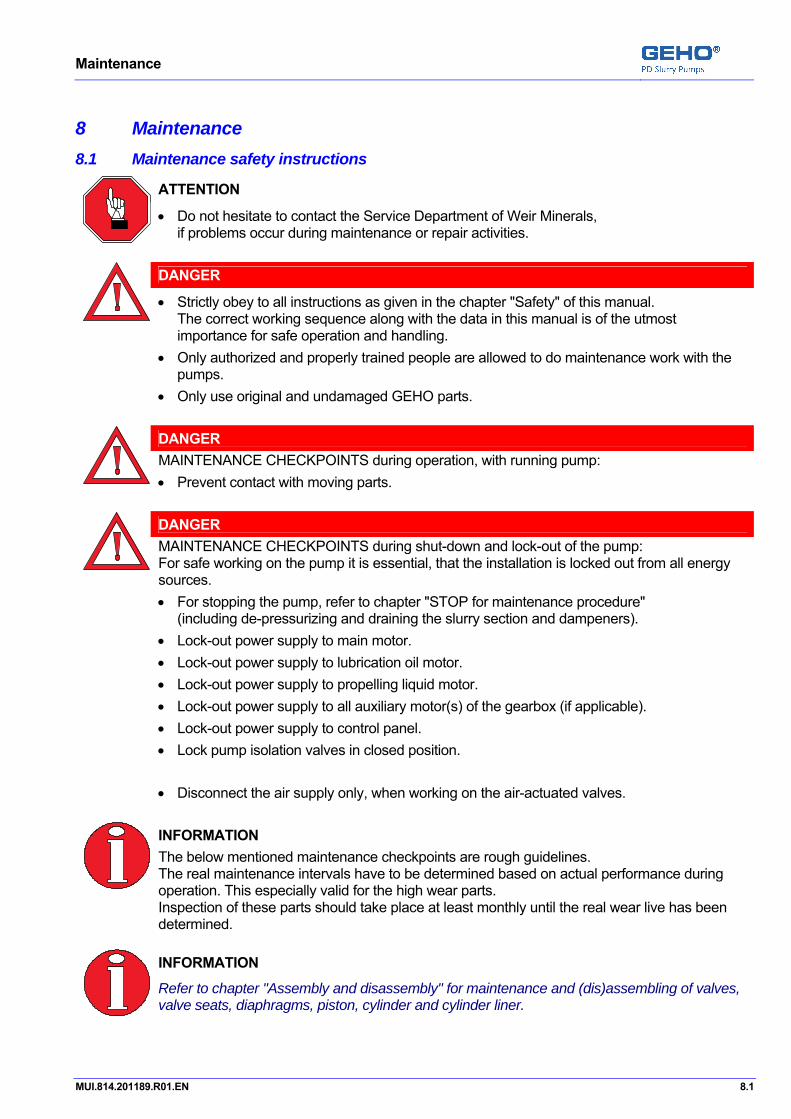
Maintenance
MUI.814.201189.R01.EN 8.1
Pos: 16 /GEHO/Heading/H1/#. Maintenance @ 0\mod_1136455430617_31.doc @ 937
8 Maintenance Pos: 17 /GEHO/Maintenance/Project/Maintenance safety ZPM+TZPM @ 1\mod_1171287274515_31.doc @ 12350
8.1 Maintenance safety instructions
ATTENTION
• Do not hesitate to contact the Service Department of Weir Minerals, if problems occur during maintenance or repair activities.
DANGER
• Strictly obey to all instructions as given in the chapter "Safety" of this manual.
The correct working sequence along with the data in this manual is of the utmost importance for safe operation and handling.
• Only authorized and properly trained people are allowed to do maintenance work with the pumps.
• Only use original and undamaged GEHO parts.
DANGER
MAINTENANCE CHECKPOINTS during operation, with running pump: • Prevent contact with moving parts.
DANGER
MAINTENANCE CHECKPOINTS during shut-down and lock-out of the pump: For safe working on the pump it is essential, that the installation is locked out from all energy sources. • For stopping the pump, refer to chapter "STOP for maintenance procedure"
(including de-pressurizing and draining the slurry section and dampeners). • Lock-out power supply to main motor. • Lock-out power supply to lubrication oil motor. • Lock-out power supply to propelling liquid motor. • Lock-out power supply to all auxiliary motor(s) of the gearbox (if applicable). • Lock-out power supply to control panel. • Lock pump isolation valves in closed position. • Disconnect the air supply only, when working on the air-actuated valves.
INFORMATION
The below mentioned maintenance checkpoints are rough guidelines. The real maintenance intervals have to be determined based on actual performance during operation. This especially valid for the high wear parts. Inspection of these parts should take place at least monthly until the real wear live has been determined.
INFORMATION
Refer to chapter "Assembly and disassembly" for maintenance and (dis)assembling of valves, valve seats, diaphragms, piston, cylinder and cylinder liner.
Pos: 18 /--- Page break --- @ 0\mod_1136278659331_0.doc @ 766
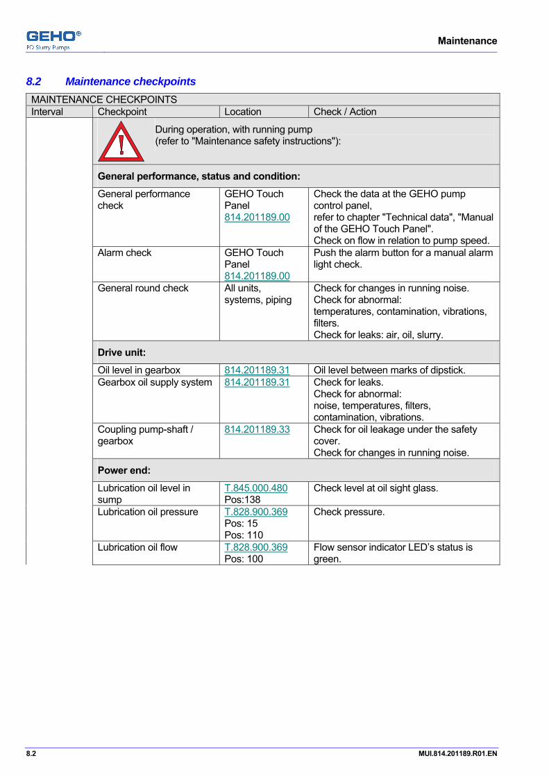
Maintenance
8.2 MUI.814.201189.R01.EN
Pos: 19 /GEHO/Heading/H2/#.# Maintenance checkpoints @ 2\mod_1193917329008_31.doc @ 19031 Pos: 20 /GEHO/Maintenance/Project/201189 TZPM1200 gear drive: checkpoints @ 5\mod_1226665692818_31.doc @ 43713
8.2 Maintenance checkpoints MAINTENANCE CHECKPOINTS Interval Checkpoint Location Check / Action
During operation, with running pump (refer to "Maintenance safety instructions"):
General performance, status and condition:
General performance check
GEHO Touch Panel 814.201189.00
Check the data at the GEHO pump control panel, refer to chapter "Technical data", "Manual of the GEHO Touch Panel". Check on flow in relation to pump speed.
Alarm check GEHO Touch Panel 814.201189.00
Push the alarm button for a manual alarm light check.
General round check All units, systems, piping
Check for changes in running noise. Check for abnormal: temperatures, contamination, vibrations, filters. Check for leaks: air, oil, slurry.
Drive unit:
Oil level in gearbox 814.201189.31 Oil level between marks of dipstick. Gearbox oil supply system 814.201189.31 Check for leaks.
Check for abnormal: noise, temperatures, filters, contamination, vibrations.
Coupling pump-shaft / gearbox
814.201189.33 Check for oil leakage under the safety cover. Check for changes in running noise.
Power end:
Lubrication oil level in sump
T.845.000.480 Pos:138
Check level at oil sight glass.
Lubrication oil pressure T.828.900.369 Pos: 15 Pos: 110
Check pressure.
Lubrication oil flow T.828.900.369 Pos: 100
Flow sensor indicator LED’s status is green.
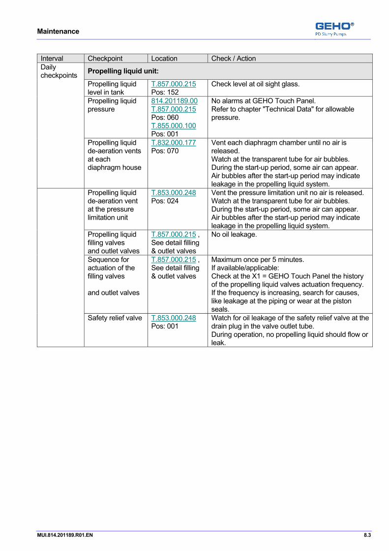
Maintenance
MUI.814.201189.R01.EN 8.3
Interval Checkpoint Location Check / Action Daily checkpoints Propelling liquid unit:
Propelling liquid level in tank
T.857.000.215 Pos: 152
Check level at oil sight glass.
Propelling liquid pressure
814.201189.00 T.857.000.215 Pos: 060 T.855.000.100 Pos: 001
No alarms at GEHO Touch Panel. Refer to chapter "Technical Data" for allowable pressure.
Propelling liquid de-aeration vents at each diaphragm house
T.832.000.177 Pos: 070
Vent each diaphragm chamber until no air is released. Watch at the transparent tube for air bubbles. During the start-up period, some air can appear. Air bubbles after the start-up period may indicate leakage in the propelling liquid system.
Propelling liquid de-aeration vent at the pressure limitation unit
T.853.000.248 Pos: 024
Vent the pressure limitation unit no air is released. Watch at the transparent tube for air bubbles. During the start-up period, some air can appear. Air bubbles after the start-up period may indicate leakage in the propelling liquid system.
Propelling liquid filling valves and outlet valves
T.857.000.215 , See detail filling & outlet valves
No oil leakage.
Sequence for actuation of the filling valves and outlet valves
T.857.000.215 , See detail filling & outlet valves
Maximum once per 5 minutes. If available/applicable: Check at the X1 = GEHO Touch Panel the history of the propelling liquid valves actuation frequency. If the frequency is increasing, search for causes, like leakage at the piping or wear at the piston seals.
Safety relief valve T.853.000.248 Pos: 001
Watch for oil leakage of the safety relief valve at the drain plug in the valve outlet tube. During operation, no propelling liquid should flow or leak.

Maintenance
8.4 MUI.814.201189.R01.EN
Interval Checkpoint Location Check / Action Daily checkpoints Slurry section:
Discharge pressure
GEHO Touch Panel 814.201189.00
Refer to chapter "Technical Data" for allowable pressure. Check for no alarms at the GEHO touch panel. Check trend graph at the GEHO touch panel.
Slurry flow GEHO Touch Panel 814.201189.00
Check for not correct relation between the pump speed and slurry flow.
Slurry valves: discharge valves suction valves
T.820.201189 Pos: 025 Pos: 026
No extreme noise inside the valve housings.
Covers of discharge valve housings, suction valve housings, pump diaphragm housings
T.831.000.460 Pos: 003 T.831.000.461 Pos: 003 T.832.000.177 Pos: 002
No leakage of slurry through covers.
Dampener diaphragm housing and cover
T.851.000.353 Pos: 001 + 002 T.851.000.393 Pos: 001 + 002 Pos: 008 T.818.080.199 Pos: 006
No leakage of slurry through covers. Check pressure indicator.
Air supply
Air filter/oiler Check the air filter/oiler on compressor unit. Add suitable oil, if necessary. Refer to: "Utility Consumption List" 814.201189.19
for the required quantity, quality and pressure
Refer to: "Catalogue information" 814.201189.22

Maintenance
MUI.814.201189.R01.EN 8.5
MAINTENANCE CHECKPOINTS Interval Checkpoint Location Check / Action “Hot torque” after initial start-up
During shut-down and lock-out of the pump (refer to "Maintenance safety instructions"):
Torque’s of all flanges, covers, bolts and nuts
Re-tighten. For correct torque, refer to chapter "Technical Data".
MAINTENANCE CHECKPOINTS Interval Checkpoint Location Check / Action
During operation, with running pump (refer to "Maintenance safety instructions"):
Do the daily checkpoints.
200 hours after initial start-up
During shut-down and lock-out of the pump (refer to "Maintenance safety instructions"):
Drive unit:
Gearbox 814.201189.31 Replace the oil. Refer to chapter "Technical Data", "Utility consumption list" for correct oil quality and quantity. Refer to "Catalogue information", "Gearbox" for manual instructions of the manufacturer.
Power end: lubrication oil replacement
Lubrication oil sump T.845.000.480 Pos: 001 Pos: 136
Drain the lubrication oil. Clean the oil sump carefully. See also Maintenance chapter "Lubrication system"
Lubrication oil sump T.828.900.369 Pos: 010 Pos: 021
Replace suction oil filter. Replace discharge oil filter. Refer to "Instrument and equipment list" for specifications. See also Maintenance chapter "Lubrication system"
Lubrication oil sump T.845.000.480 Pos: 001
Fill the carter with new oil. Refer to chapter "Technical Data", "Utility consumption list" for correct oil quality and quantity See also Maintenance chapter "Lubrication system"

Maintenance
8.6 MUI.814.201189.R01.EN
INFORMATION
To achieve reliable and economical pump performance, we recommend regular oil quality checks by an oil laboratory. Oil change intervals depend on the operation conditions and oil quality and oil quantity. We recommend for normal conditions an oil check interval of 2000 working hours or 3 month. Refer to chapter "Technical Data", "Utility consumption list" for correct oil quality and quantity.
MAINTENANCE CHECKPOINTS Interval Checkpoint Location Check / Action Drive unit:
After each operating period of 2000 working hours (or 3 months of operation, whatever comes first)
Oil in gearbox 814.201189.31 Do the oil quality laboratory check. Take an oil sample and send it in to the oil supplier laboratory, for a recommen-dation of a time schedule for replacing the oil.
Depending on the result, if necessary: Replace the oil. Refer for instructions and details to the table for 200 hours interval.
Power end:
Lubrication oil tank
T.845.000.480 Pos:001
Do the oil quality laboratory check. Take an oil sample and send it in to the oil supplier laboratory, for a recommen-dation of a time schedule for replacing the oil.
Depending on the result, if necessary: Replace the oil. Refer for instructions and details to the table for 200 hours interval.

Maintenance
MUI.814.201189.R01.EN 8.7
MAINTENANCE CHECKPOINTS Interval Checkpoint Location Check / Action
During operation, with running pump (refer to "Maintenance safety instructions"):
Do the daily checkpoints.
Electrical Installation:
Check function of the diaphragm stroke control system:
Initiators transfer signal to PLC. Filling outlet valve actuated after signal from initiator to PLC.
Indication on Touch Panel.
GEHO Touch Panel 814.201189.00
Check for indication on the GEHO Touch Panel.
Working of initiators, propelling liquid filling valves, outlet/drain valves
T.832.000.177 Pos: 012 T.814.201189.43 Pos: 001 T.857.000.215 See: Detail filling & outlet valves
Maximum once per 5 minutes. If available/applicable: Check at X1 GEHO Touch Panel the history of the propelling liquid valves actuation frequency. If the frequency is increasing, search for causes, like leakage at the piping or wear at the piston seals.
Slurry section:
After each operating period of 4000 working hours (or ½ year of operation, whatever comes first)
Covers of discharge valve housings, suction valve housings, pump diaphragm housings
T.820.201189 Pos: 025 Pos: 026 Pos: 030
No leakage of slurry through covers.
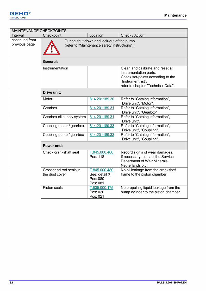
Maintenance
8.8 MUI.814.201189.R01.EN
MAINTENANCE CHECKPOINTS Interval Checkpoint Location Check / Action continued from previous page
During shut-down and lock-out of the pump (refer to "Maintenance safety instructions"):
General:
Instrumentation Clean and calibrate and reset all instrumentation parts. Check set-points according to the "Instrument list", refer to chapter "Technical Data".
Drive unit:
Motor 814.201189.30 Refer to “Catalog information”, "Drive unit", "Motor".
Gearbox 814.201189.31 Refer to “Catalog information”, "Drive unit", "Gearbox".
Gearbox oil supply system 814.201189.31 Refer to “Catalog information”, "Drive unit".
Coupling motor / gearbox 814.201189.33 Refer to “Catalog information”, "Drive unit", "Coupling".
Coupling pump / gearbox 814.201189.33 Refer to “Catalog information”, "Drive unit", "Coupling".
Power end:
Check.crankshaft seal T.845.000.480 Pos: 118
Record sign’s of wear damages. If necessary, contact the Service Department of Weir Minerals Netherlands b.v.
Crosshead rod seals in the dust cover
T.845.000.480 See, detail X. Pos: 080 Pos: 081
No oil leakage from the crankshaft frame to the piston chamber.
Piston seals T.835.000.175 Pos: 020 Pos: 021
No propelling liquid leakage from the pump cylinder to the piston chamber.
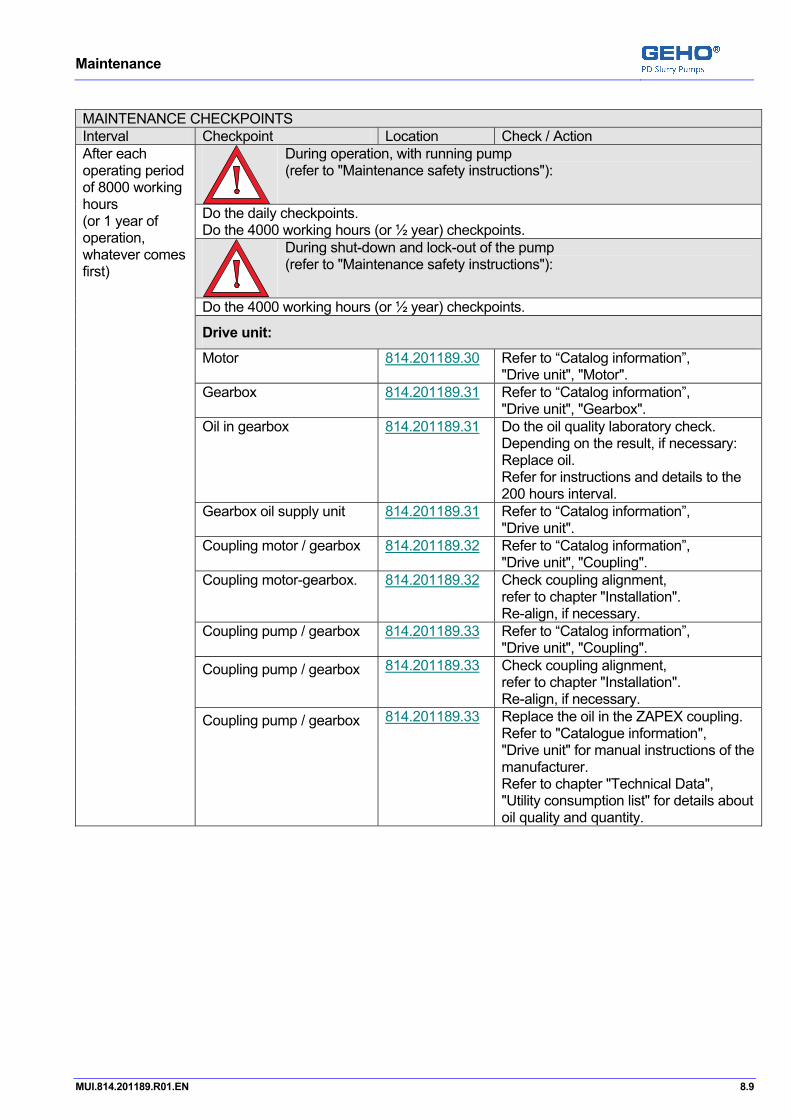
Maintenance
MUI.814.201189.R01.EN 8.9
MAINTENANCE CHECKPOINTS Interval Checkpoint Location Check / Action
During operation, with running pump (refer to "Maintenance safety instructions"):
Do the daily checkpoints. Do the 4000 working hours (or ½ year) checkpoints.
After each operating period of 8000 working hours (or 1 year of operation, whatever comes first)
During shut-down and lock-out of the pump (refer to "Maintenance safety instructions"):
Do the 4000 working hours (or ½ year) checkpoints. Drive unit:
Motor 814.201189.30 Refer to “Catalog information”, "Drive unit", "Motor".
Gearbox 814.201189.31 Refer to “Catalog information”, "Drive unit", "Gearbox".
Oil in gearbox 814.201189.31 Do the oil quality laboratory check. Depending on the result, if necessary: Replace oil. Refer for instructions and details to the 200 hours interval.
Gearbox oil supply unit 814.201189.31 Refer to “Catalog information”, "Drive unit".
Coupling motor / gearbox 814.201189.32 Refer to “Catalog information”, "Drive unit", "Coupling".
Coupling motor-gearbox. 814.201189.32 Check coupling alignment, refer to chapter "Installation". Re-align, if necessary.
Coupling pump / gearbox 814.201189.33 Refer to “Catalog information”, "Drive unit", "Coupling".
Coupling pump / gearbox 814.201189.33 Check coupling alignment, refer to chapter "Installation". Re-align, if necessary.
Coupling pump / gearbox 814.201189.33 Replace the oil in the ZAPEX coupling. Refer to "Catalogue information", "Drive unit" for manual instructions of the manufacturer. Refer to chapter "Technical Data", "Utility consumption list" for details about oil quality and quantity.

Maintenance
8.10 MUI.814.201189.R01.EN
MAINTENANCE CHECKPOINTS Interval Checkpoint Location Check / Action continued from previous page Power end:
Lubrication oil sump T.845.000.480 Pos: 001
Do the oil quality laboratory check. Take an oil sample and send it in to the oil supplier laboratory, for a recommendation of a time schedule for replacing the oil.
Depending on the result, if necessary: Replace oil. Refer for instructions and details to the 200 hours interval.
Air vent/filter of oil sump, located on inspection cover
T.845.000.480 Pos: 140
Change the air vent/filter. Refer to Instrument and equipment list for specifications.
Piston nut T.835.000.175 Pos: 010
Check the required tightening torque according to chapter "Technical Data" and re-tighten if required.
Piston clamping piece T.845.000.480 Pos: 046
Check the required tightening torque according to chapter "Technical Data" and re-tighten if required.
Propelling liquid unit:
Propelling liquid oil tank T.857.000.215 Pos: 150
Do the oil quality laboratory check. Take an oil sample and send it in to the oil supplier laboratory, for a recommendation of a time schedule for replacing the oil.
Propelling liquid oil tank T.857.000.215 Pos: 150
Depending on the result, if necessary: Replace oil. Refer for instructions and details to "Maintenance", "Lubrication system".
Propelling liquid accumulator
T.857.000.215 Pos: 040
Check the pre-charge pressure.
Piston seals T.835.000.175 Pos: 020 Pos: 021
Check for no oil leakage.
Cylinder liner T.835.000.175 Pos: 002
Inspect surface of cylinder liner or replace.
Filling valves, outlet/drain valve: valve seat
T.857.000.215 See, detail filling and outlet valves
Inspect and replace if there is any leakage between the valves and valves seats.
Filling valves, outlet/drain valves: spindle / seal guide
T.857.000.215 See, detail filling and outlet valves. See also: T.853.000.068 Pos: 001 Pos: 005 Pos: 011 T.853.000.110 Pos: 001 Pos: 005 Pos: 011
Open valve cover, disassemble valve housing from base plate. Inspect 2/2 diaphragm for perforation or damage. Inspect slide bearing and guide ring between valve spindle and valve housing. Replace slide bearing and / guide ring if required. Before re-assembly: fill space between the two guide rings with suitable grease.

Maintenance
MUI.814.201189.R01.EN 8.11
Interval Checkpoint Location Check / Action continued from previous page Slurry section:
Slurry chambers: discharge valves suction valves pump diaphragm chamber
T.831.000.460 T.831.000.461 T.832.000.177
Carefully inspect the slurry chambers.
Pump diaphragm T.832.000.177 Pos: 019
Replace the pump diaphragms. Refer to chapter "Assembly and disassembly".
Pulsation dampener diaphragm
T.851.000.353 Pos: 006 T.851.000.393 Pos: 003
Replace the pulsation dampener diaphragm. For (dis-)assembling instructions, refer to chapter "Assembly and disassembly". Pre-charge the pulsation dampener, refer to chapter "Transport and installation".
Pos: 21 /--- Page break --- @ 0\mod_1136278659331_0.doc @ 766

Maintenance
8.12 MUI.814.201189.R01.EN
Pos: 22 /GEHO/Heading/H2/#.# Lubrication system @ 0\mod_1152094184716_31.doc @ 5126
8.3 Lubrication system Pos: 23 /GEHO/Maintenance/Procedures/Lubrication system/### Check the oil level @ 0\mod_1138630463309_31.doc @ 2208
8.3.1 Check the oil level The oil level gauge is located at the side of the power end.
1 Check the lubrication oil level (A) at the oil level gauge.
2 If necessary, then fill up the lubrication oil. Refer to the "UTILITY CONSUMPTION LIST" in chapter “Technical data”, for the correct oil type quality and the estimated oil quantity.
A
Figure 8.1: Lubrication oil level gauge
Pos: 24 /GEHO/Maintenance/Procedures/Lubrication system/Change the discharge oil filter/Single oil filter @ 0\mod_1152779323482_31.doc @ 5251 ┐┐┐
8.3.2 Change the oil filter Refer to chapter "Technical data", "Drawings + lists + instruments", "Instrument and equipment list" and the chapter "Catalogue information" for the specification of the oil filer and for details and specifications of the filter housing.
1 Set the lever to position.
2 Remove the filter cover.
3 Remove the old filter.
4 Clean the filter cover and housing.
5 Install the new filter.
6 Check the O-ring. If nessessary exchange
the O-ring.
7 Install the filter cover.
8 Set the lever to position.
Figure 8.2: Single oil filter with bypass
Pos: 25 /GEHO/Maintenance/Procedures/Frame unit/### Clean the oil sump @ 0\mod_1156845386000_31.doc @ 5891
8.3.3 Clean the lubrication oil sump 1 Drain the lubrication oil. Refer to chapter “Change the oil”. 2 Open the frame unit cover. 3 Clean the oil sump. 4 Replace the oil filter. Refer to chapter “Replace the oil filter”. Pos: 26 /GEHO/Maintenance/Procedures/Lubrication system/### Replace the suction oil filter @ 0\mod_1152098136341_31.doc @ 5155
Maintenance
MUI.814.201189.R01.EN 8.13
8.3.4 Replace the pump lubrication oil and the oil suction filter
8.3.4.1 Remove the oil 1 Open the frame unit cover. 2 Remove the oil from the oil sump.
Drain the oil through the oil drain valve, ore use a pump.
8.3.4.2 Remove the suction oil filter 1 Loosen the oil filter cover. 2 Remove the oil filter cover. 3 Remove the oil filter from the oil filter housing. 4 Clean:
• the oil filter cover. • the oil filter housing. • the oil sump.
8.3.4.3 Install the oil suction filter Refer to the "INSTRUMENT AND EQUIPMENT LIST" in chapter "Technical data", "Drawings + lists + instruments" and also to chapter "Catalogue information" for the specification of the oil filer and for details and specifications of the filter housing.
1 Install a new suction oil filter into the oil filter housing. 2 Check the O-ring. If necessary, exchange O-ring. 3 Install the oil filter cover. 4 Tighten the oil filter cover.
8.3.4.4 Fill the oil Refer to chapter "Start and stop procedure", "Initial lubrication filling" for the procedure.
1 Fill in the new oil. Use a pump. 2 After replacing the oil, check the liquid level at the level gauge. 3 After starting-up the pump, check again the oil level at the level gauge. 4 If necessary, add or drain oil. Pos: 27 /GEHO/Maintenance/Procedures/Frame unit/### Replace the venting filter-top-nofig @ 2\mod_1174995485185_31.doc @ 12836
8.3.5 Replace the venting filter at the pump power end Refer to the "INSTRUMENT AND EQUIPMENT LIST" in chapter "Technical data", "Drawings + lists + instruments" and also to chapter "Catalogue information" for details and specifications of the air filer.
1 Open the air filter cover. 2 Remove the filter element from the air filter
housing. 3 Insert the new filter element into the air
filter housing. 4 Close the air filter cover.
Pos: 28 /GEHO/Heading/H2/#.# Propelling liquid system @ 0\mod_1152094190955_31.doc @ 5132
8.4 Propelling liquid system Pos: 29 /GEHO/Maintenance/Procedures/Propelling liquid system/Change proliq venting filter @ 0\mod_1152098314051_31.doc @ 5168
8.4.1 Replace the venting filter at the propelling liquid system Refer to the "INSTRUMENT AND EQUIPMENT LIST" in chapter "Technical data", "Drawings + lists + instruments" and also to chapter "Catalogue information" for details and specifications of the air filer.
1 Open the air filter cover. 2 Remove the filter element from the air filter
housing. 3 Insert the new filter element into the air
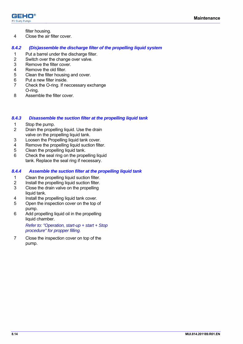
Maintenance
8.14 MUI.814.201189.R01.EN
filter housing. 4 Close the air filter cover.
Pos: 30 /GEHO/Maintenance/Procedures/Propelling liquid system/(Dis)assemble instruction propelling liquide discharge filter @ 4\mod_1208526739408_31.doc @ 28635
8.4.2 (Dis)assemble the discharge filter of the propelling liquid system 1 Put a barrel under the discharge filter. 2 Switch over the change over valve. 3 Remove the filter cover. 4 Remove the old filter. 5 Clean the filter housing and cover. 6 Put a new filter inside. 7 Check the O-ring. If neccessary exchange
O-ring. 8 Assemble the filter cover.
Pos: 31 /GEHO/Maintenance/Procedures/Propelling liquid system/(Dis)assemble instruction propelling liquide suction filter in tank @ 5\mod_1221134876001_31.doc @ 38422
8.4.3 Disassemble the suction filter at the propelling liquid tank 1 Stop the pump. 2 Drain the propelling liquid. Use the drain
valve on the propelling liquid tank. 3 Loosen the Propelling liquid tank cover. 4 Remove the propelling liquid suction filter. 5 Clean the propelling liquid tank. 6 Check the seal ring on the propelling liquid
tank. Replace the seal ring if necessary.
8.4.4 Assemble the suction filter at the propelling liquid tank 1 Clean the propelling liquid suction filter. 2 Install the propelling liquid suction filter. 3 Close the drain valve on the propelling
liquid tank. 4 Install the propelling liquid tank cover. 5 Open the inspection cover on the top of
pump. 6 Add propelling liquid oil in the propelling
liquid chamber. Refer to: "Operation, start-up + start + Stop procedure" for propper filling.
7 Close the inspection cover on top of the pump.
Pos: 32 /--- Section break - Odd page --- @ 0\mod_1136277036628_0.doc @ 765
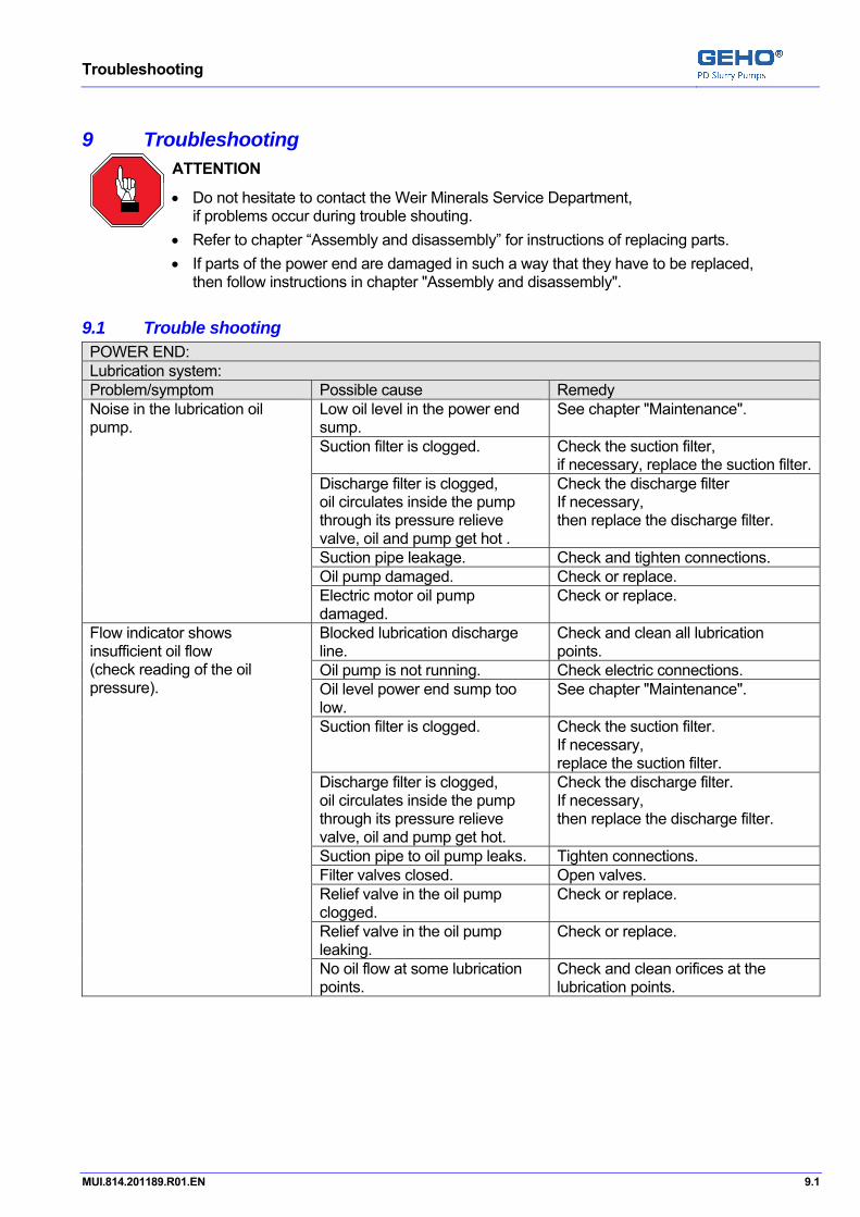
Troubleshooting
MUI.814.201189.R01.EN 9.1
Pos: 33 /GEHO/Heading/H1/#. Troubleshooting @ 0\mod_1152772213698_31.doc @ 5244
9 Troubleshooting Pos: 34 /GEHO/Troubleshooting/Attention - Trouble shouting @ 0\mod_1138615626939_31.doc @ 2139
ATTENTION
• Do not hesitate to contact the Weir Minerals Service Department, if problems occur during trouble shouting.
• Refer to chapter “Assembly and disassembly” for instructions of replacing parts. • If parts of the power end are damaged in such a way that they have to be replaced,
then follow instructions in chapter "Assembly and disassembly". Pos: 35 /GEHO/Troubleshooting/Trouble shooting table (T)ZPM-gear drive @ 1\mod_1169136012360_31.doc @ 11845
9.1 Trouble shooting POWER END: Lubrication system: Problem/symptom Possible cause Remedy
Low oil level in the power end sump.
See chapter "Maintenance".
Suction filter is clogged. Check the suction filter, if necessary, replace the suction filter.
Discharge filter is clogged, oil circulates inside the pump through its pressure relieve valve, oil and pump get hot .
Check the discharge filter If necessary, then replace the discharge filter.
Suction pipe leakage. Check and tighten connections. Oil pump damaged. Check or replace.
Noise in the lubrication oil pump.
Electric motor oil pump damaged.
Check or replace.
Blocked lubrication discharge line.
Check and clean all lubrication points.
Oil pump is not running. Check electric connections. Oil level power end sump too low.
See chapter "Maintenance".
Suction filter is clogged. Check the suction filter. If necessary, replace the suction filter.
Discharge filter is clogged, oil circulates inside the pump through its pressure relieve valve, oil and pump get hot.
Check the discharge filter. If necessary, then replace the discharge filter.
Suction pipe to oil pump leaks. Tighten connections. Filter valves closed. Open valves. Relief valve in the oil pump clogged.
Check or replace.
Relief valve in the oil pump leaking.
Check or replace.
Flow indicator shows insufficient oil flow (check reading of the oil pressure).
No oil flow at some lubrication points.
Check and clean orifices at the lubrication points.

Troubleshooting
9.2 MUI.814.201189.R01.EN
Abnormal mechanical noise: Problem/symptom Possible cause Remedy
Malfunction of lubrication system Check the lubrication system. Noise caused by loosened connections and transmitted to power end:
Loose piston.
See chapter "Maintenance".
Loose piston rod/crosshead rod connection.
See chapter "Maintenance".
Loose crosshead rod/on crosshead.
Tighten the crosshead rod.
Incorrect settings/worn parts of crosshead guides, crosshead bearing, connecting rod bearing, crankshaft bearing or other.
Correct setting or replace the worn parts.
Power end bearings damaged. Check for temperature rise and replace if necessary.
Possible cause Remedy Malfunction of lubrication system.
Check the lubrication system.
Power end gears worn/damaged.
See the general note.
Hammering noise synchronous with dead points of the piston stroke.
Power end bearings damaged. Check for temperature rise and replace if necessary.
Overheating: Problem/symptom Possible cause Remedy
Malfunction of lubrication system.
Check lubrication system and settings or relief valves, see "Instrument List".
Incorrect setting or worn parts. Correct setting or replace worn parts.
Overheating of the lubrication oil (maximum temperature 80°C).
Gears worn. Replace. Malfunction of lubrication system.
Check the lubrication system. Overheating of the crosshead liner.
Damaged running surfaces. Replace the damaged parts. Bearings damaged. Replace the bearings. Overheating of the bearing
housing. Wandered settings or worn bearings.
Correct the settings or replace.

Troubleshooting
MUI.814.201189.R01.EN 9.3
LIQUID END: Propelling liquid section: Problem/symptom Possible cause Remedy
Leakage in filling pipe. Tighten connections. Leakage of outlet valve. Replace the outlet valve parts. Too low air pressure. See chapter "Maintenance". Filling valve malfunction. Check or replace the valve or the
valve parts. Leakage of the cylinder liner seal. Check and replace if necessary. Pump diaphragm rupture (this will cause a knocking noise in the pump chamber during the discharge stroke).
Replace the diaphragm.
Air in the propelling liquid chamber. De-aerate the propelling liquid chambers.
Piston seal rings leaking. Replace the seal rings. Leakage in the propelling liquid chamber.
Repair the leakage’s.
Propelling liquid filling: Filling valves too often in operation.
Leaking of the safety valves or valve seats.
Check and replace if necessary.
Leakage of the filling valve. Check and replace the filling valve or seat.
Propelling liquid drain: Outlet valves to often in operating. Rupture diaphragm of the filling valve. Check and replace.
Too low air pressure. Re-adjust the air pressure. Malfunction of the outlet valve. Check and replace if necessary. Leakage of the cylinder liner seals. Check and replace.
Outlet valves to often in operating
Leakage of the piston seals. Check and replace. Leaking of the propelling liquid piping. Tighten the connections. Leaking of the pressure relief valve. Check the set-points and replace the
worn parts. Propelling liquid accumulator not proper pre-charged.
Check the pre-charging.
Drain valve is leaking. Check and replace.
Propelling liquid pump is starting too often.
Damaged running surfaces. Replaced the damaged parts. Diaphragm rupture. Pump not proper filled and timed. Following the start sequence.
Refer to "Description of the pump control system".
Settlement of sediment in the diaphragm housing.
Clean the diaphragm housing. Follow the suitable flushing procedure before the pump stop.
Overfilling by the propelling liquid system.
Check proper functioning of all pump initiators with help of a magnet.
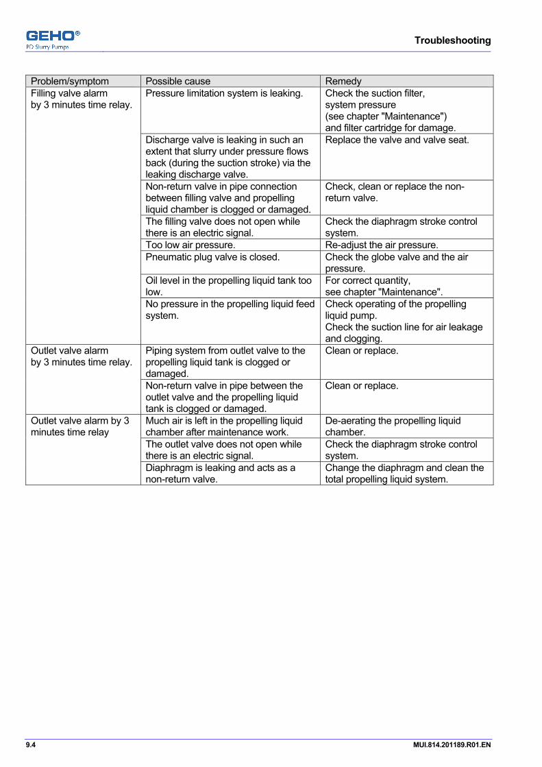
Troubleshooting
9.4 MUI.814.201189.R01.EN
Problem/symptom Possible cause Remedy
Pressure limitation system is leaking. Check the suction filter, system pressure (see chapter "Maintenance") and filter cartridge for damage.
Discharge valve is leaking in such an extent that slurry under pressure flows back (during the suction stroke) via the leaking discharge valve.
Replace the valve and valve seat.
Non-return valve in pipe connection between filling valve and propelling liquid chamber is clogged or damaged.
Check, clean or replace the non-return valve.
The filling valve does not open while there is an electric signal.
Check the diaphragm stroke control system.
Too low air pressure. Re-adjust the air pressure. Pneumatic plug valve is closed. Check the globe valve and the air
pressure. Oil level in the propelling liquid tank too low.
For correct quantity, see chapter "Maintenance".
Filling valve alarm by 3 minutes time relay.
No pressure in the propelling liquid feed system.
Check operating of the propelling liquid pump. Check the suction line for air leakage and clogging.
Piping system from outlet valve to the propelling liquid tank is clogged or damaged.
Clean or replace. Outlet valve alarm by 3 minutes time relay.
Non-return valve in pipe between the outlet valve and the propelling liquid tank is clogged or damaged.
Clean or replace.
Much air is left in the propelling liquid chamber after maintenance work.
De-aerating the propelling liquid chamber.
The outlet valve does not open while there is an electric signal.
Check the diaphragm stroke control system.
Outlet valve alarm by 3 minutes time relay
Diaphragm is leaking and acts as a non-return valve.
Change the diaphragm and clean the total propelling liquid system.

Troubleshooting
MUI.814.201189.R01.EN 9.5
SLURRY SECTION: (abnormal noise and/or vibration) GENERAL: If the noise coming from the fluid end, then an attempt should be made to localize the source with the aid of a wrench or a stethoscope. If the noise can be localized, then it probably is of a mechanical source. If the noise seems general and difficult to locate, then the source might be a fluid knock. Problem/symptom Possible cause Remedy
Partially blocking of suction valve(s).
Check the permitted lifting of suction valve.
(Partially) blocked suction line. Check the clogged or not completely opened valves in the suction line.
Not completely filled propelling liquid chamber.
Filling valves in operation (see lamps on control panel).
Air in propelling liquid chamber(s).
De-aerating the propelling liquid chambers.
During the discharge stroke excessive vibrations or knocking due to not complete filling of one or more pump chambers during the suction stroke. Mostly also knocking in the discharge valves.
Air in slurry chamber De-aerating the slurry chamber. Suction feed pressure too low. Increase the suction pressure. Slurry temperature too high. Cooling of the slurry. Pulsation dampener not correctly pre-charged.
Pre-charge according to chapter "Maintenance".
Hammering noise near of just behind mid-stroke. Fluid hammer due to fluid separation (void) following collapsing in the pump chamber. This collapsing causes a hammering noise in the suction valves and a surge pressure well in the suction line. Diagnose by reducing pump speed.
Air level in Air vessel too low. Manually add a small amount of air until the hammering noise is disappeared.
Valve seal ring worn / valve seat worn (resulting in mechanical noise).
Replace the seal ring / valve seat.
Loose piston/cylinder liner. Tighten the connection. For the correct torque see chapter "Maintenance".
Hammering noise in the piston dead points.
Suction or discharge valve, valve guide or valve spring worn.
Check and replace.
Slurry leaking under high velocity between the valve(s) and seat will cause wash out damage to valve(s) and seat or valve housing.
Check the valves and seats and replace if necessary.
If noise is heard during discharge stroke, then the problem is induced in the suction valve, if heard during suction stroke, then the problem is induced in discharge valve.
Check the valves and seats and replace if necessary.
Jetting noise in suction or discharge valve(s). Depending on the severity of the problem, a decreasing discharge flow may be observed.
No closing of suction or discharge valves.
Check and close the valves.
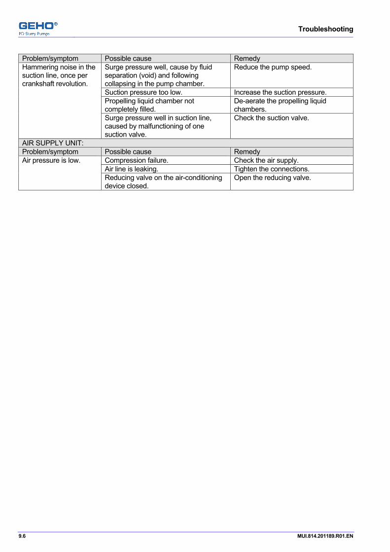
Troubleshooting
9.6 MUI.814.201189.R01.EN
Problem/symptom Possible cause Remedy
Surge pressure well, cause by fluid separation (void) and following collapsing in the pump chamber.
Reduce the pump speed.
Suction pressure too low. Increase the suction pressure. Propelling liquid chamber not completely filled.
De-aerate the propelling liquid chambers.
Hammering noise in the suction line, once per crankshaft revolution.
Surge pressure well in suction line, caused by malfunctioning of one suction valve.
Check the suction valve.
AIR SUPPLY UNIT: Problem/symptom Possible cause Remedy
Compression failure. Check the air supply. Air line is leaking. Tighten the connections.
Air pressure is low.
Reducing valve on the air-conditioning device closed.
Open the reducing valve.
Pos: 36 /--- Page break --- @ 0\mod_1136278659331_0.doc @ 766

Troubleshooting
MUI.814.201189.R01.EN 9.7
Pos: 37 /GEHO/Troubleshooting/## Diaphragm pulsation dampener @ 0\mod_1156318158348_31.doc @ 5783
9.2 Trouble shooting at a diaphragm pulsation dampener Problem/symptom Possible causes and solutions
Safety
DANGER: Avoid breathing in nitrogen.
Make sure that the pulsation dampener is depressurized before loosening the pulsation dampener cover. Always loosen the cover nuts controlled.
General The pre-charge pressure at the diaphragm pulsation dampener shall be checked and noted at regular intervals.
• Keep a log book for settings and changes of the pre-charge pressure, so you can compare and observe changes.
The pre-charge pressure will normally be registered at the pressure gauge.
ATTENTION
If there is no liquid pressure at the pulsation dampener bottom, then the pressure gauge indicates only the pre-charge pressure.
If the liquid pressure at the pulsation dampener bottom is higher then the pre-charge pressure, then the pressure gauge indicates also the working pressure at the liquid site of diaphragm.
Under certain conditions the pressure gauge or filling line can be damaged or clogged with slurry and may then not indicate the right pressure. It is therefore important to recognize symptoms associated with a pre-charge pressure that is too low or too high. Such symptoms are excessive pressure fluctuations in piping or shock and vibrations in pump and piping.
Pre-charge pressure to high. 1 Check for causes.
Pre-charge pressure to low.
DANGER: Avoid breathing in nitrogen.
Determine the reason for any loss of gas and remedy the condition.
1 Do a leakage test. Refer below to the section “Diaphragm outside leakage test”.
2 Check for other causes.
Pre-charge pressure loss. Determine the reason for any loss of gas and remedy the condition.
1 Do a leakage test. Refer below to the section “Diaphragm outside leakage test”.
2 Increase the pre-charge pressure. Refer to chapter “Pre-charging the diaphragm pulsation dampener”.
Measuring at the pressure gauge 1 The pressure gauge (manometer) is damaged.

Troubleshooting
9.8 MUI.814.201189.R01.EN
Problem/symptom Possible causes and solutions (manometer) excessive pressure fluctuations in the suction line or discharge line, or heavy vibrations.
Replace the pressure gauge. 2 Pre-charge pressure to low.
Check the pre-charge pressure. Refer to chapter “Pre-charging the diaphragm pulsation dampener”.
Filling valve leakage.
DANGER: Avoid breathing in nitrogen.
1 Tighten loose threads. 2 Do a outside leakage test. If there is still a leakage, then: 3 Release the nitrogen pressure carefully by opening slowly the filling
valve. 4 Replace seal ring. 5 Replace filling valve.
Pressure gauge leakage at the gauge cover or at the lock cover.
1 Replace the pressure gauge.
Pressure gauge leakage at the thread or at the nipples.
1 Tighten loose threads. 2 Replace threaded nipples. 3 Replace pressure gauge.
Diaphragm leakage.
DANGER: Avoid breathing in nitrogen.
Fluid can have clogged the filling valve or the pressure gauge.
1 Release the nitrogen pressure carefully by opening slowly the filling valve.
2 Replace the diaphragm. Refer to “Replacing the pulsation dampener diaphragm”.
Diaphragm pulsation dampener outside leakage test
DANGER: Avoid breathing in nitrogen.
1 Apply a leak detector to the pulsation dampener. Use soapy water. 2 Watch for bubbles. 3 Use the table above to solve the problem.
If the outside leakage test fails and the pressure still drops, then a diaphragm leakage is probably. Pos: 38 /--- Page break --- @ 0\mod_1136278659331_0.doc @ 766
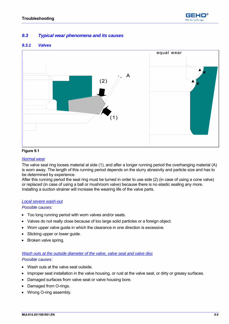
Troubleshooting
MUI.814.201189.R01.EN 9.9
Pos: 39 /GEHO/Troubleshooting/## Typical wear (T)ZPM @ 1\mod_1169136581763_31.doc @ 11849
9.3 Typical wear phenomena and its causes
9.3.1 Valves
Figure 9.1
Normal wear The valve seal ring looses material at side (1), and after a longer running period the overhanging material (A) is worn away. The length of this running period depends on the slurry abrasivity and particle size and has to be determined by experience. After this running period the seal ring must be turned in order to use side (2) (in case of using a cone valve) or replaced (in case of using a ball or mushroom valve) because there is no elastic sealing any more. Installing a suction strainer will increase the wearing life of the valve parts.
Local severe wash-out Possible causes:
• Too long running period with worn valves and/or seats. • Valves do not really close because of too large solid particles or a foreign object. • Worn upper valve guide in which the clearance in one direction is excessive. • Sticking upper or lower guide. • Broken valve spring.
Wash outs at the outside diameter of the valve, valve seat and valve disc Possible causes:
• Wash outs at the valve seat outside. • Improper seat installation in the valve housing, or rust at the valve seat, or dirty or greasy surfaces. • Damaged surfaces from valve seat or valve housing bore. • Damaged from O-rings. • Wrong O-ring assembly.
Troubleshooting
9.10 MUI.814.201189.R01.EN
9.3.2 Pump diaphragm Normal wear by fatigue: If the diaphragm is broken by fatigue, then it shows near the clamping edge a crack and mostly more surfaces cracks, especially at the propelling liquid side.
Blown up diaphragm A blown up diaphragm by too much propelling liquid shows at the top section of the diaphragm a crack and some scratches due to deformation of the diaphragm in the discharge valve opening.
Teared-off in-vulcanized cone-plate in diaphragm The cause might be fluid hammer in the slurry section for extended period or seizing of monitoring rod.
Damage at the propelling liquid side of the diaphragm If rubber has loosened at the in-vulcanized cone-plate area, then the pump was probably running with insufficient propelling liquid and the vulcanized valve has touched the rear wall. Possible causes:
• Pump discharge valve leaking, keeping propelling liquid chamber under discharge pressure during suction stroke.
9.3.3 Pulsation dampener diaphragm Normal wear by fatigue If the diaphragm is broken by fatigue, then it shows a crack near the biggest diameter, and perhaps more local surface cracks.
Damage of the in-vulcanized valve Rubber from the diaphragm surface, near the vulcanized valve, lost by striking against the pulsation dampener inlet. Possible causes:
• Pre-charge pressure of the pulsation dampener was too high.

Troubleshooting
MUI.814.201189.R01.EN 9.11
9.3.4 Piston Normal wear Normal worn piston seal rings show an equal wear around the outer diameter, so there is no pre-sealing effect any more.
Seal rings granulated surface The rubber was burned by insufficient lubrication and cooling. Possible causes:
• Piston flushing system works insufficiently. • Running of the piston in a dry cylinder liner.
Grooves over the piston seal rings Possible causes:
• Piston was running in a worn grooved cylinder liner. • Propelling liquid chamber was not clean. • Flushing oil is contaminated. • Diaphragm rupture.
Severe wear at a part of the circumference Possible causes:
• The piston guide ring is worn (mostly lower side). • Alignment of the piston rod - crosshead rod was incorrect: • Damaged contact surface. • Dirty contact surface. • Piston flushing pipe partly clogged, which causes insufficient lubrication of the piston seal rings at one
side.
9.3.5 Cylinder liner Normal wear A normal worn liner shows a light grooved surface. The inner diameter is increased, mostly in the center of the piston stroke where the piston velocity is highest. The wear is raising rapidly when the hard layer in the cylinder liner is worn away.
Grooved cylinder liner after a relatively short operation time. Possible causes:
• Propelling liquid chamber is insufficiently flushed and cleaned after diaphragm rupture. • Propelling liquid in the tank is contaminated and flushing oil is dirty. • Piston guide ring worn, by which the piston body rubs against the cylinder liner.
Severe wear at a part of the circumference Possible causes:
• The piston guide ring was worn (mostly the lower side). Pos: 40 /--- Section break - Odd page --- @ 0\mod_1136277036628_0.doc @ 765
Troubleshooting
9.12 MUI.814.201189.R01.EN

Assembly and disassembly
MUI.814.201189.R01.EN 10.1
Pos: 41 /GEHO/Heading/H1/#. Assembly and disassembly @ 0\mod_1136455386113_31.doc @ 935
10 Assembly and disassembly Pos: 42 /GEHO/Assembly and Disassembly/General/Introduction - Safety notes (T)ZPM @ 0\mod_1145882820736_31.doc @ 3352
ATTENTION
• Do not hesitate to contact the Service Department of Weir Minerals Netherlands b.v., if problems occur during maintenance or repair activities.
INFORMATION
Refer to the drawings in chapter "Parts - Lists and drawings" (pump section) for correct positions of the ID numbers, mentioned in the text and not visible figures.
Refer to chapter "Parts - Lists and drawings (special tools)" for the use of special tools.
DANGER
• Strictly obey to all instructions as given in the chapter "Safety" of this manual.
The correct working sequence along with the data in this manual is of the utmost importance for safe operation and handling.
• Only authorized and properly trained people are allowed to work with the pumps. • Only use original and undamaged GEHO parts.
DANGER
Lockout checklist For safe working on the pump it is essential that the installation is locked out from all energy sources. • For stopping the pump refer to chapter "Start and stop". • Lock-out power supply to the main motor. • Lock-out power supply to the lubrication oil motor. • Lock-out power supply to the propelling liquid motor. • Lock-out power supply to the control panel. • Lock all the pump isolation valves in the closed position. • Lock-out the power supply of all other applicable components. • Stop and dis-connect the air supply only, when working on the air-actuated valves. Refer to chapter "Stop, maintenance", "Stop air supply".
WARNING
The heavy parts of the pumps have a hoisting eye, or have the possibility to install a hoisting eye for transportation purposes. • Always transport heavy parts by using these hoisting eyes.

Assembly and disassembly
10.2 MUI.814.201189.R01.EN
WARNING
Some tools operate hydraulically: • Before pressurizing a hydraulic tool:
Check the hydraulic pump, hose, nipples and tool and de-aerate the part and tools. • During pressurizing and 1 minute after reaching pressure level,
no person is allowed to be in front of the tool, always stay aside. • Watch the pressure gauge.
If pressure does not build-up steady, then stud bolts are not stretching equally. If the pistons coming out further, then this indicates that the stud bolts are failing. If this happens, then:
• Relief the oil pressure, replace these stud bolts by new ones and restart. Pos: 43 /--- Page break --- @ 0\mod_1136278659331_0.doc @ 766

Assembly and disassembly
MUI.814.201189.R01.EN 10.3
Pos: 44 /GEHO/Heading/H2/#.# Special tools @ 1\mod_1166540615553_31.doc @ 11465
10.1 Special tools Pos: 45 /GEHO/Assembly and Disassembly/General/Manual rotation/### via socket wrench gearbox (T)ZPM @ 0\mod_1145881095763_31.doc @ 3340
10.1.1 Socket wrench
10.1.1.1 Manual rotation of the pump shaft with a socket wrench. Manual rotation the pump shaft is required for: • For "priming" of the pump, turning a piston in a necessary position for the start-up priming procedure. • For assembling or dis-assembling of several components within the pump.
DANGER
Be aware that during manual rotation of the crankshaft, the torque will vary and the crankshaft can reach the top dead center. There is a possibility of a "running away" pump crankshaft, turning forwards or backwards. • Therefore the lever must be held firmly to resist "runaway". • NEVER do this work alone.
Procedure:
DANGER
1 Switch-off the power from the main motor. 2 Make sure that the main motor can not be operated during the maintenance work.
3 Opening the drain valve of the discharge line, to release the pump pressure on the slurry section. 4 Remove the safety guard from the non-driven end of the high speed gearbox shaft.
This will actuate the electric switch and will inhibit the start of the electric main motor.
ATTENTION Avoid that the pump shaft rotates without lubrication. 5 Start the lubrication pump. 6 Check that the lubrication system delivers the oil quantity.
7 Place the socket wrench on the hexagon shaft extension of the gearbox and manually rotate the pump.
After the manual rotation: 8 Remove the socket wrench. 9 Mount the safety guard. Pos: 46 /GEHO/Assembly and Disassembly/General/Hydraulic pump unit/Air driven @ 0\mod_1156403099735_31.doc @ 5821
10.1.2 Air driven hydraulic pump Some tools are operated hydraulically. The air driven oil pump generates a hydraulic pressure, displayed at the pressure gauge. A high pressure hose is connected to the hydraulic pump. All hydraulic tools are fitted with quick release connectors (“nipples”).
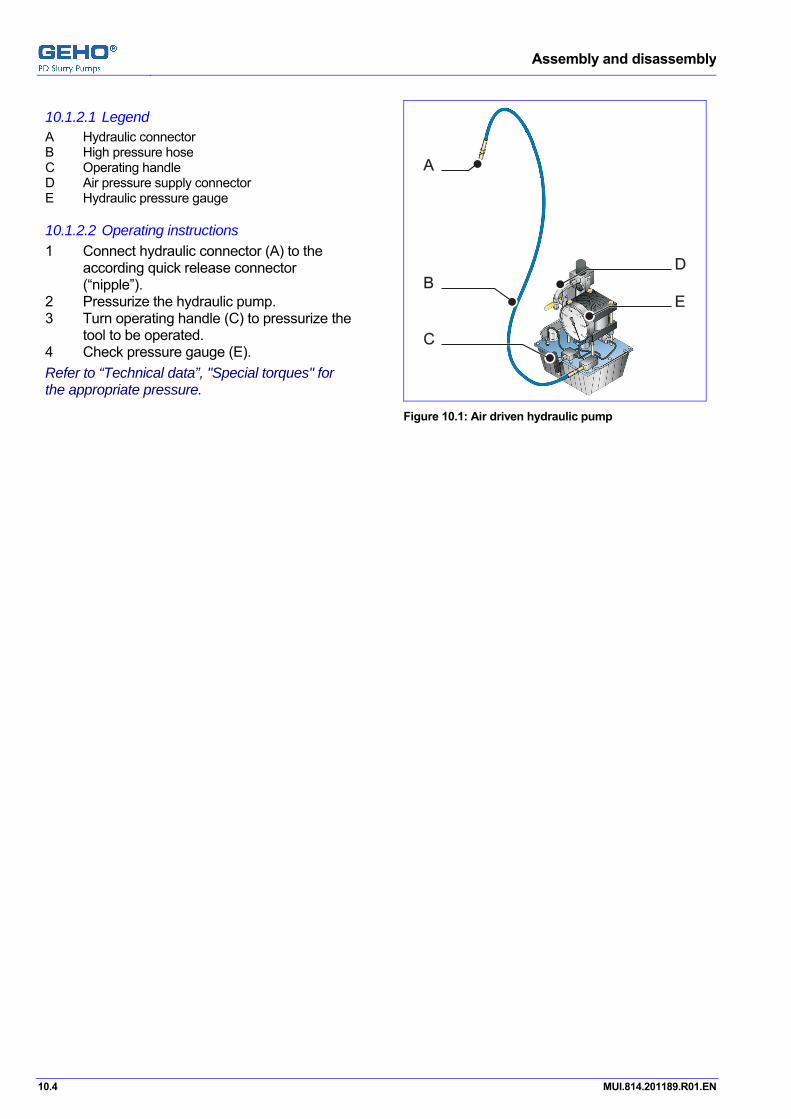
Assembly and disassembly
10.4 MUI.814.201189.R01.EN
10.1.2.1 Legend A Hydraulic connector B High pressure hose C Operating handle D Air pressure supply connector E Hydraulic pressure gauge
10.1.2.2 Operating instructions 1 Connect hydraulic connector (A) to the
according quick release connector (“nipple”).
2 Pressurize the hydraulic pump. 3 Turn operating handle (C) to pressurize the
tool to be operated. 4 Check pressure gauge (E). Refer to “Technical data”, "Special torques" for the appropriate pressure.
A
B
D
E
C
Figure 10.1: Air driven hydraulic pump
Pos: 47 /--- Page break --- @ 0\mod_1136278659331_0.doc @ 766

Assembly and disassembly
MUI.814.201189.R01.EN 10.5
Pos: 48 /GEHO/Heading/H2/#.# Valves, discharge angular @ 1\mod_1170947685604_31.doc @ 12232
10.2 Valves, discharge line, angular model Pos: 49.1 /GEHO/Heading/H3/#.#.# Valve housing cover @ 0\mod_1147174241226_31.doc @ 3690
10.2.1 Valve housing cover Pos: 49.2 /GEHO/Heading/H4/#.#.#.# Disassembly @ 0\mod_1147174347836_31.doc @ 3696
10.2.1.1 Disassembly Pos: 49.3 /GEHO/Assembly and Disassembly/Valve unit/Conical valves/Valve housing cover/Hydraulic/Remove, High pressure @ 1\mod_1162208470115_31.doc @ 6720
1 Remove the protection guard from the nipple (G) at the valve housing cover (F).
2 Connect the hose of the hydraulic pump unit to nipple (G).
3 Connect the hexagon nipple of the flexible hose to the hydraulic pump unit.
4 Pressurize the hydraulic pump unit. Refer to “Technical data” for the correct pressure.
5 Tighten the nuts (A). Use the pin. 6 Loosen the outside nuts (E). 7 Unscrew the outside nuts (E) completely
against the inside nuts (C). 8 Depressurize the hydraulic pump unit. 9 Unscrew the nuts (C). 10 Lift the valve housing cover (F). 11 Remove the valve housing cover.
Use a lifting device. Use the provided lifting eye.
ECA B FD G
Figure 10.2: Schematics of a hydraulically operated high pressure valve cover
Pos: 49.4 /--- Page break --- @ 0\mod_1136278659331_0.doc @ 766

Assembly and disassembly
10.6 MUI.814.201189.R01.EN
Pos: 49.5 /GEHO/Heading/H4/#.#.#.# Assembly @ 0\mod_1147174319423_31.doc @ 3693
10.2.1.2 Assembly Pos: 49.6 /GEHO/Assembly and Disassembly/Valve unit/Conical valves/Valve housing cover/Hydraulic/Install, High pressure @ 1\mod_1162292450237_31.doc @ 6742
1 Clean and grease the sealing surfaces. 2 Insert a new square gasket into the valve
housing cover (F). 3 Fit the valve housing cover (F) to the valve
housing. 4 Connect the hydraulic high-pressure pump
to the hydraulic connector (G). 5 Unscrew on the outside nuts (E) to the
inside nut (C). 6 Hand tighten the nuts (C). 7 Reset all hydraulic pistons:
Push all pistons (B) down to the start-position (B supports on F).
Check that the pistons (B) are even with the valve housing cover (F).
8 Pressurize the hydraulic pump. Tighten the outside nuts (E). Refer to “Technical data”, “Special torques” for the correct procedure and pressures and torques.
9 Loosen the nuts (A). Use the pin.
10 Depressurize the hydraulic pump unit. 11 Remove the hydraulic pump unit. 12 Put the protecting guard to the hydraulic
connector (G).
ECA B FD G
Figure 10.3: Schematics of the hydraulic cover mechanism at a high pressure valve
Pos: 50.1 /GEHO/Heading/H3/#.#.# Conical valve @ 0\mod_1147176114890_31.doc @ 3735
10.2.2 Conical valve Pos: 50.2 /GEHO/Assembly and Disassembly/Valve unit/Conical valves/Valve/Remove, Angular, Standard @ 1\mod_1161247034668_31.doc @ 6533
10.2.2.1 Disassembly 1 Make sure the pump is not under pressure.2 Remove the valve housing cover. Refer to chapter "Remove the valve housing cover".
3 Remove the square gasket. 4 Remove the compression spring. 5 Remove the conical valve.
Figure 10.4: Remove the conical valve
Pos: 50.3 /GEHO/Assembly and Disassembly/Valve unit/Conical valves/Valve/Install, Angular @ 1\mod_1161247316353_31.doc @ 6535

Assembly and disassembly
MUI.814.201189.R01.EN 10.7
10.2.2.2 Assembly 1 Insert the conical valve. 2 Insert the compression spring 3 Install a new square gasket. 4 Install the valve housing cover. Refer to section "Install the valve housing cover".
Figure 10.5: Insert the conical valve
Pos: 51.1 /GEHO/Heading/H3/#.#.# Valve seat @ 0\mod_1147176079227_31.doc @ 3732
10.2.3 Valve seat Pos: 51.2 /GEHO/Assembly and Disassembly/Valve unit/Conical valves/Valve seat/Angular/Remove HySeat angular @ 0\mod_1147180524829_31.doc @ 3774
10.2.3.1 Disassembly
Remove the valve seat, using the hydraulic seat connector 1 Remove the valve housing cover. Refer to chapter "Valve housing cover", "Disassembly".
2 Remove the conical valve. Refer to chapter "Conical valve", "Disassembly".
WARNING
• Re-install the valve housing cover, to prevent getting hit by a valve seat.
3 Install the valve housing cover. Refer to chapter "Valve housing cover", "Assembly".
4 Remove the protection guard from the hydraulic connector. 5 Connect the hydraulic pump unit to the connector at the valve housing. 6 Pressurize the hydraulic pump unit until the valve seat is loose. 7 Release the pressure from the hydraulic pump unit. 8 Disconnect the hydraulic pump unit. 9 Remove the valve housing cover. Refer to chapter "Valve housing cover", "Disassembly".
10 Remove the valve seat from the valve housing. Pos: 51.3 /GEHO/Assembly and Disassembly/Valve unit/Conical valves/Valve seat/Angular/Remove HyTool API 12+ @ 1\mod_1161675180316_31.doc @ 6588

Assembly and disassembly
10.8 MUI.814.201189.R01.EN
Remove the valve seat, using a hydraulic special tool set 1 Remove the valve housing cover. Refer to "Remove the valve cover".
2 Remove the valve and spring. Refer to "Remove the valve".
3 Screw threaded spindle (C) into puller (E). 4 Place puller (E) under the valve seat. 5 Put centering plate (D) with hydraulic
tool (B) to the valve housing. 6 Tighten nut (A) until hydraulic tool (B) is
compressed in its final position. 7 Connect the hydraulic pump to the
connector of hydraulic tool (B). 8 Pressurize the pump until the valve seat is
loose. 9 Depressurize the pump. 10 Remove the pump. 11 Remove the valve seat.
A
B
D
E
C
Figure 10.6: Using the hydraulic valve seat tool.
Pos: 51.4 /GEHO/Assembly and Disassembly/Valve unit/Conical valves/Valve seat/Angular/Install MechTool API 12- @ 0\mod_1147179105600_31.doc @ 3769
10.2.3.2 Assembly
Install the valve seat, using a mechanical tool 1 Clean the valve seat. 2 Clean the bore in the valve housing. 3 Make sure that they are free of dust, paint,
or oil. 4 Insert new O-rings into the grooves at the
valve seat. 5 Insert valve seat (D) into the bore in the
valve housing. 6 Put valve seat tool (C) to the valve seat. 7 Tap valve seat tool (B) until the valve seat
fits. Use a hammer (A).
8 Remove the valve seat tool. 9 Make sure that the valve seat is mounted
correctly. Pull the valve seat by hand.
A
B
D
C
Figure 10.7: Using the mechanic valve seat tool.
Pos: 52 /GEHO/Heading/H2/#.# Valves, suction inline @ 1\mod_1170947706445_31.doc @ 12236

Assembly and disassembly
MUI.814.201189.R01.EN 10.9
10.3 Valves, suction side, inline model Pos: 53.1.1 /GEHO/Heading/H3/#.#.# Valve housing cover @ 0\mod_1147174241226_31.doc @ 3690
10.3.1 Valve housing cover Pos: 53.1.2 /GEHO/Assembly and Disassembly/Valve unit/Conical valves/Valve housing cover/Hydraulic/Remove, Standard, Inline @ 1\mod_1171550323234_31.doc @ 12480
10.3.1.1 Disassembly 1 Remove the protection guard from the
nipple (F) at the valve housing cover (D). 2 Connect the hose of the hydraulic pump
unit to nipple (F). 3 Connect the hexagon nipple of the flexible
hose to the hydraulic pump unit. 4 Pressurize the hydraulic pump unit. Refer to “Technical data” for the correct pressure.
5 Loosen the outside nuts (C). 6 Unscrew the outside nuts (C) to the inside
nuts (D). 7 Depressurize the hydraulic pump unit. 8 Unscrew all nuts. 9 Lift the valve housing cover (B).
Use the push-off screws (E). 10 Remove the valve housing cover (B).
Use the valve housing cover lifting bar.
Figure 10.8: Schematics of a hydraulic operated inline valve cover
Pos: 53.1.3 /GEHO/Assembly and Disassembly/Valve unit/Conical valves/Valve housing cover/Hydraulic/Install, Standard. Inline @ 1\mod_1171558792656_31.doc @ 12484
10.3.1.2 Assembly 1 Clean and grease the sealing surfaces. 2 Insert a new square gasket into the valve
housing cover (B). 3 Cut the jack-off screws (F). 4 Fit the valve housing cover (B) to the valve
housing (A). Use the valve housing cover lifting bar.
5 Connect the hydraulic pump unit to the hydraulic connector (F).
6 Unscrew on the outside nuts (C) to the inside nut (D).
7 Hand tighten the nuts (D). 8 Push the pistons back in 0-position. 9 Make sure, that the pistons are even with
the valve housing cover (B). 10 Pressurize the hydraulic pump unit. Refer to chapter “Technical data” for the correct pressure.
11 Hand tighten the outside nuts (D). Refer to chapter “Special torques” for the correct torque.
12 Depressurize the hydraulic pump unit. 13 Remove the hydraulic pump unit. 14 Put the protecting guard to the hydraulic
connector (F).
Figure 10.9: Schematics of the hydraulic operated inline valve cover
Pos: 53.2 /--- Page break --- @ 0\mod_1136278659331_0.doc @ 766

Assembly and disassembly
10.10 MUI.814.201189.R01.EN
Pos: 53.3 /GEHO/Assembly and Disassembly/Valve unit/Inline, conical/API 11-/Valve housing cover lifting bar, API 7 - API 11 @ 1\mod_1162210456239_31.doc @ 6730
Valve housing cover lifting bar
ATTENTION Use the special tool "Lifting bar", when handling the valve housing cover. Refer to chapter "Special tools".
1 Loosen the screw (E) so that the ring (C) is
movable. 2 Screw the thread (A) of lifting spindle (B)
into the valve housing cover. 3 Set the ring (C) to a groove on the lifting
spindle (A). Make sure that the ring is in front of the diaphragm housing cover.
4 Tighten the screw (E) to attach the ring (C).
A B D EC
Figure 10.10: The valve housing cover lifting bar.
Pos: 53.4 /--- Page break --- @ 0\mod_1136278659331_0.doc @ 766

Assembly and disassembly
MUI.814.201189.R01.EN 10.11
Pos: 53.5.1 /GEHO/Heading/H3/#.#.# Conical valve @ 0\mod_1147176114890_31.doc @ 3735
10.3.2 Conical valve Pos: 53.5.2 /GEHO/Heading/H4/#.#.#.# Disassembly @ 0\mod_1147174347836_31.doc @ 3696
10.3.2.1 Disassembly Pos: 53.5.3 /GEHO/Assembly and Disassembly/Valve unit/Conical valves/Valve/Remove, Inline, API 7+ @ 1\mod_1162205774047_31.doc @ 6716
1 Make sure the pump is not under pressure.2 Remove the valve housing cover. Refer to "Remove the valve housing cover".
3 Remove the pin (D). 4 Put the spring tensioner (F) with the fork
over the clamping piece (C). 5 Put the support of the spring tensioner (F)
to the stud bolt. 6 Pull the lever (F) up to push the clamping
piece (C) and the compression spring (B) down.
A B D E FC
Figure 10.11: Use the spring tensioner
7 Pull the valve support (E) and turn the valve support (E) by 90°.
8 Release the lever slowly.
E
Figure 10.12: Remove the valve support.
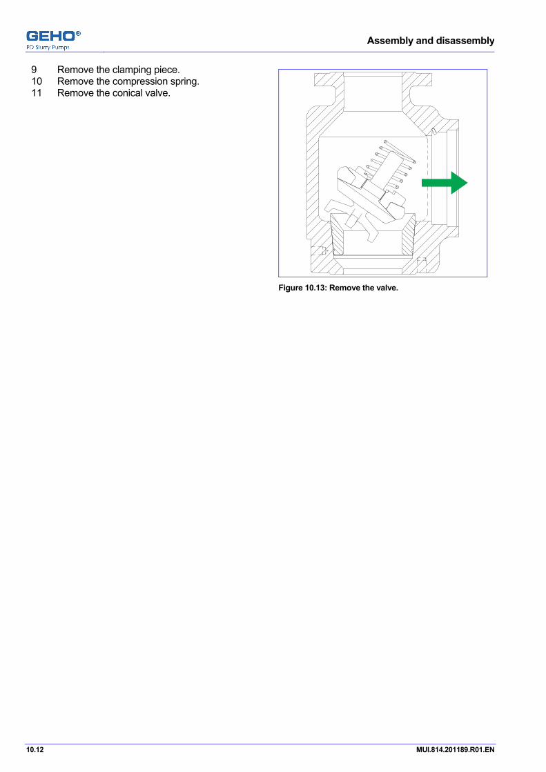
Assembly and disassembly
10.12 MUI.814.201189.R01.EN
9 Remove the clamping piece. 10 Remove the compression spring. 11 Remove the conical valve.
Figure 10.13: Remove the valve.
Pos: 53.5.4 /--- Page break --- @ 0\mod_1136278659331_0.doc @ 766

Assembly and disassembly
MUI.814.201189.R01.EN 10.13
Pos: 53.5.5 /GEHO/Heading/H4/#.#.#.# Assembly @ 0\mod_1147174319423_31.doc @ 3693
10.3.2.2 Assembly Pos: 53.5.6 /GEHO/Assembly and Disassembly/Valve unit/Conical valves/Valve/Install, Inline, Spring tensioner @ 1\mod_1161247434813_31.doc @ 6539
1 Insert the conical valve (A). 2 Insert the compression spring (B). 3 Insert the clamping piece (C). 4 Insert the valve support (E).
A B EC
Figure 10.14: Insert the conical valve
5 Put the support of the spring tensioner (F)
to the stud bolt. 6 Put the spring tensioner (F) with the fork
over the clamping peace (C). 7 Pull the lever (F) up to push the clamping
piece (C) and the compression spring (B) down.
8 Turn the valve support (E) by 90°. 9 Release the spring tensioner slowly. 10 Install the pin (D). 11 Install a new square gasket, if necessary. 12 Install the valve housing cover. Refer to section "Install the valve housing cover".
A B D E FC
Figure 10.15: Assemble the valve support.
Pos: 53.6 /--- Page break --- @ 0\mod_1136278659331_0.doc @ 766

Assembly and disassembly
10.14 MUI.814.201189.R01.EN
Pos: 53.7.1 /GEHO/Heading/H3/#.#.# Valve seat @ 0\mod_1147176079227_31.doc @ 3732
10.3.3 Valve seat Pos: 53.7.2 /GEHO/Heading/H4/#.#.#.# Disassembly @ 0\mod_1147174347836_31.doc @ 3696
10.3.3.1 Disassembly Pos: 53.7.3 /GEHO/Assembly and Disassembly/Valve unit/Conical valves/Valve seat/Inline/Remove HySeat, inline @ 1\mod_1171469939990_31.doc @ 12452
Remove the valve seat, using the hydraulic seat connector 1 Remove the valve housing cover. Refer to chapter "Valve housing cover", "Disassembly".
2 Remove the conical valve. Refer to chapter "Conical valve", "Disassembly".
3 Remove the protection guard from the hydraulic connector. 4 Connect the hydraulic pump unit to the connector at the valve housing. 5 Pressurize the hydraulic pump unit until the valve seat is loose. 6 Release the pressure from the hydraulic pump unit. 7 Disconnect the hydraulic pump unit. 8 Remove the valve seat from the valve housing. Pos: 53.7.4 /GEHO/Assembly and Disassembly/Valve unit/Conical valves/Valve seat/Inline/Remove HyTool API 12+ @ 1\mod_1161675113450_31.doc @ 6586
Remove the valve seat (inline valves), using a hydraulic special tool set 1 Remove the valve housing cover. Refer to "Remove the valve cover".
2 Remove the valve and spring. Refer to "Remove the valve".
3 Connect spindle (A) with puller (F). 4 Place puller (F) under valve seat (E). 5 Put centering plate (D) above valve
seat (E). 6 Put hydraulic tool (C) above centering
plate (D). 7 Tighten nut (B) until hydraulic tool (C) is
compressed in its final position. 8 Connect the hydraulic pump to the
connector of hydraulic tool (C). 9 Pressurize the pump until valve seat (E) is
loose. 10 Depressurize the pump. 11 Disconnect the pump. 12 Remove the tool set with the valve seat.
A
B
C
D
E
F
Figure 10.16: Using the hydraulic valve seat tool.
Pos: 53.7.5 /--- Page break --- @ 0\mod_1136278659331_0.doc @ 766

Assembly and disassembly
MUI.814.201189.R01.EN 10.15
Pos: 53.7.6 /GEHO/Assembly and Disassembly/Valve unit/Conical valves/Valve seat/Inline/Install HyTool API 12+inline @ 1\mod_1161675066413_31.doc @ 6584
Install the valve seat (inline valves), using a hydraulic tool set 1 Clean the valve seat. 2 Clean the bore in the valve housing. 3 Make sure that they are free of dust, paint
or oil. 4 Insert new O-rings into the grooves at the
valve seat. 5 Insert the valve seat into the bore in the
valve housing. 6 Place valve seat tool (D) to the valve
seat (F). 7 Put the block (A) with the threaded rod and
the nuts (B) into the valve housing. 8 Tighten the 2 nuts (B), until hydraulic
tool (C) is compressed in its final position. 9 Connect the hydraulic pump to the
connector of hydraulic tool (E) of hydraulic tool (C).
10 Pressurize the pump until a metal to metal contact between the valve seat an the valve housing is achieved.
11 Make sure that the valve seat is mounted correctly. Pull the valve seat by hand.
A
B
D
E
C
F
Figure 10.17: Using the hydraulic valve seat tool.
Pos: 54 /GEHO/Assembly and Disassembly/Valve unit/Conical valves/Valve disk/### Disassembly and assembly @ 1\mod_1161260471084_31.doc @ 6573
10.3.4 Conical valve assembly
10.3.4.1 Disassemble the valve disk A Conical valve B Valve disc lock nut C Valve disc 1 Remove the valve disc lock nut (B). 2 Remove the valve disc (C) from the conical
valve (A).
A B C
Figure 10.18: The valve

Assembly and disassembly
10.16 MUI.814.201189.R01.EN
10.3.4.2 Assemble the valve disk 1 Make sure that all valve parts are clean,
dry and free of lubricant. 2 Put the valve disc (C) to the conical
valve (A). 3 Apply a small amount of grease or soft
soap to the surface (Y) of the valve disc lock nut (B).
ATTENTION Do NOT use grease based on mineral oil.
4 Make sure that there is no grease on
surface (X).
A B CYX
Figure 10.19: The valve
5 Put the valve nut wrench (A) to the assembled valve (B).
6 Tighten the valve disc lock nut. Refer to "Special torques" for the correct torque.
7 Make sure that the valve disc does not turn with the valve disc lock nut.
8 Make sure that valve disc lock nut and the valve disc are in full contact.
A B
Figure 10.20: Assemble the valve with the valve nut wrench.
Pos: 55.1 /GEHO/Heading/H2/#.# Piston unit @ 0\mod_1152094187891_31.doc @ 5129

Assembly and disassembly
MUI.814.201189.R01.EN 10.17
10.4 Piston unit Pos: 55.2 /GEHO/Assembly and Disassembly/Piston unit/TZPM/Overview @ 1\mod_1163689690473_31.doc @ 8653
A Piston rod B Thrust ring C Threaded bolts D Piston guide ring E Chevron seal rings F Piston nut G Retaining plate H Cylinder liner
A D G HFCB E
Figure 10.21: Piston unit overview
Pos: 55.3 /GEHO/Heading/H3/#.#.# Disassembly @ 0\mod_1146735769451_31.doc @ 3613
10.4.1 Disassembly Pos: 55.4 /GEHO/Assembly and Disassembly/Piston unit/TZPM/Disassembly @ 1\mod_1161678281536_31.doc @ 6591
10.4.1.1 Preparation 1 Drain the propelling liquid. 2 Remove the top cover plate of the piston unit. 3 Move the piston unit to the most forward position. 4 Remove the clamping piece between piston rod and crosshead rod. 5 Move the crosshead to the most backward position. 6 If applicable, then disconnect the flushing pipes. 7 Remove the thrust ring lock nuts. 8 Remove the upper threaded bolts. 9 Remove the thrust ring.
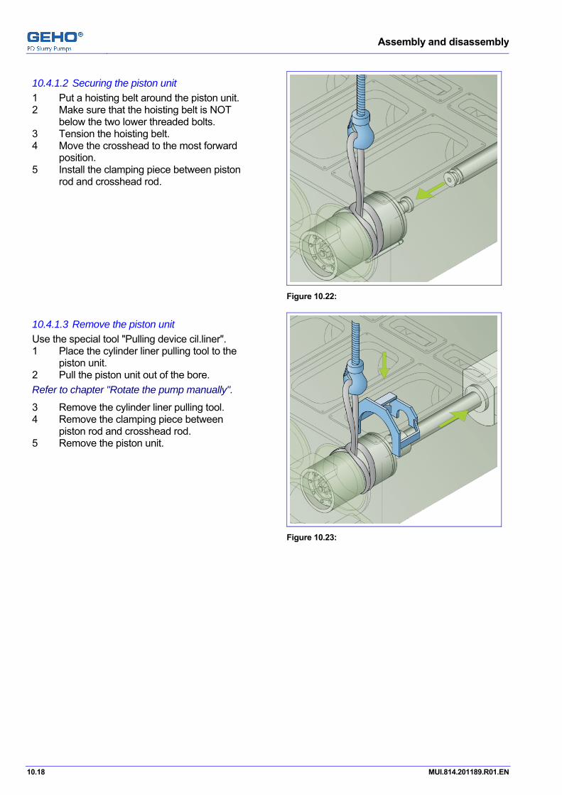
Assembly and disassembly
10.18 MUI.814.201189.R01.EN
10.4.1.2 Securing the piston unit 1 Put a hoisting belt around the piston unit. 2 Make sure that the hoisting belt is NOT
below the two lower threaded bolts. 3 Tension the hoisting belt. 4 Move the crosshead to the most forward
position. 5 Install the clamping piece between piston
rod and crosshead rod.
Figure 10.22:
10.4.1.3 Remove the piston unit Use the special tool "Pulling device cil.liner". 1 Place the cylinder liner pulling tool to the
piston unit. 2 Pull the piston unit out of the bore. Refer to chapter "Rotate the pump manually".
3 Remove the cylinder liner pulling tool. 4 Remove the clamping piece between
piston rod and crosshead rod. 5 Remove the piston unit.
Figure 10.23:
Pos: 55.5 /--- Page break --- @ 0\mod_1136278659331_0.doc @ 766
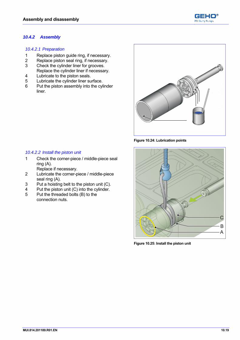
Assembly and disassembly
MUI.814.201189.R01.EN 10.19
Pos: 55.6 /GEHO/Heading/H3/#.#.# Assembly @ 0\mod_1146735726056_31.doc @ 3610
10.4.2 Assembly Pos: 55.7 /GEHO/Assembly and Disassembly/Piston unit/TZPM/Assembly @ 1\mod_1163689511253_31.doc @ 8647
10.4.2.1 Preparation 1 Replace piston guide ring, if necessary. 2 Replace piston seal ring, if necessary. 3 Check the cylinder liner for grooves.
Replace the cylinder liner if necessary. 4 Lubricate to the piston seals. 5 Lubricate the cylinder liner surface. 6 Put the piston assembly into the cylinder
liner.
Figure 10.24: Lubrication points
10.4.2.2 Install the piston unit 1 Check the corner-piece / middle-piece seal
ring (A). Replace if necessary.
2 Lubricate the corner-piece / middle-piece seal ring (A).
3 Put a hoisting belt to the piston unit (C). 4 Put the piston unit (C) into the cylinder. 5 Put the threaded bolts (B) to the
connection nuts.
A
B
C
Figure 10.25: Install the piston unit
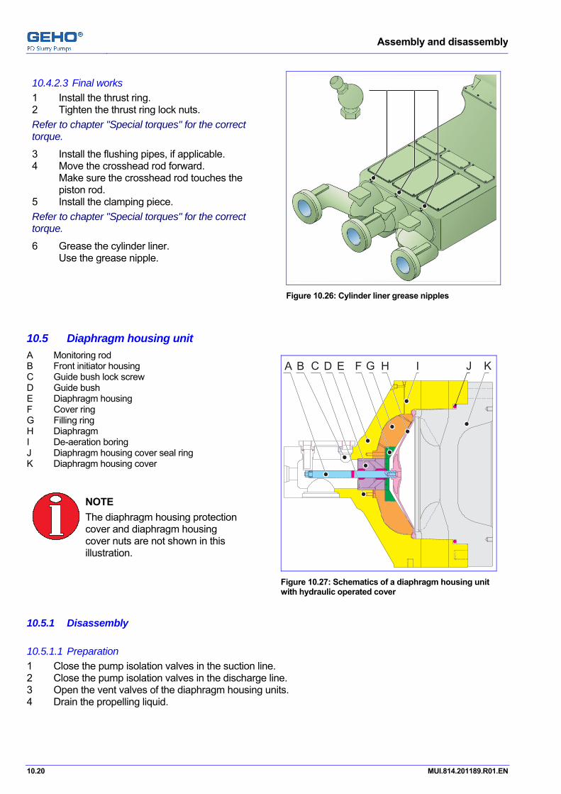
Assembly and disassembly
10.20 MUI.814.201189.R01.EN
10.4.2.3 Final works 1 Install the thrust ring. 2 Tighten the thrust ring lock nuts. Refer to chapter "Special torques" for the correct torque.
3 Install the flushing pipes, if applicable. 4 Move the crosshead rod forward.
Make sure the crosshead rod touches the piston rod.
5 Install the clamping piece. Refer to chapter "Special torques" for the correct torque.
6 Grease the cylinder liner. Use the grease nipple.
Figure 10.26: Cylinder liner grease nipples
Pos: 56.1 /GEHO/Heading/H2/#.# Diaphragm housing unit @ 0\mod_1152094180650_31.doc @ 5123
10.5 Diaphragm housing unit Pos: 56.2 /GEHO/Assembly and Disassembly/Diaphragm housing unit/General/Overview, filling ring / high pressure @ 1\mod_1165391188521_31.doc @ 9015
A Monitoring rod B Front initiator housing C Guide bush lock screw D Guide bush E Diaphragm housing F Cover ring G Filling ring H Diaphragm I De-aeration boring J Diaphragm housing cover seal ring K Diaphragm housing cover
NOTE
The diaphragm housing protection cover and diaphragm housing cover nuts are not shown in this illustration.
A FDCB E IHG J K
Figure 10.27: Schematics of a diaphragm housing unit with hydraulic operated cover
Pos: 56.3 /GEHO/Heading/H3/#.#.# Disassembly @ 0\mod_1146735769451_31.doc @ 3613
10.5.1 Disassembly Pos: 56.4 /GEHO/Assembly and Disassembly/Diaphragm housing unit/Diaphragm housing cover/Common/Disassembly, Preparation @ 1\mod_1164881888391_31.doc @ 8826
10.5.1.1 Preparation 1 Close the pump isolation valves in the suction line. 2 Close the pump isolation valves in the discharge line. 3 Open the vent valves of the diaphragm housing units. 4 Drain the propelling liquid. Pos: 56.5 /GEHO/Assembly and Disassembly/Diaphragm housing unit/Diaphragm housing cover/Hydraulic/Loosen, single piston @ 0\mod_1156333407963_31.doc @ 5796

Assembly and disassembly
MUI.814.201189.R01.EN 10.21
10.5.1.2 Diaphragm housing cover
Loosen the diaphragm housing cover 1 Remove the protection cover from the
diaphragm housing unit (D). 2 Place the hydraulic tension ring unit (B) to
the stud bolts. Use an appropriate lifting device. Use the lifting eye (A).
3 Reset all hydraulic pistons: Push all hydraulic pistons at the tension ring down into the start-position (all pistons support on the tension ring).
Check that all piston heads (B) are even with the surface of the tension ring unit (B).
4 Tighten all tension ring nuts (C). 5 Connect the hydraulic pump to the quick
release connector (E). 6 Fill the hydraulic tension ring (B) with oil
and de-aerate: • Loosen the blind plug (F). • Activate the hydraulic pump until hydraulic
oil leaks out. • Tighten the blind plug (F).
7 Pressurize the hydraulic tension ring unit. Refer for the correct pressure to chapter "Technical data", "Special torques", "Diaphragm housing unit".
B
AF
D
C
E
Figure 10.28: Install the hydraulic tension ring unit.
Loosen the diaphragm cover nuts 1 Loosen all diaphragm housing cover
nuts (D) with the pin (E). 2 Release the pressure from the hydraulic
tension ring unit. 3 Remove the hydraulic pump. 4 Loosen all tension ring nuts (F). 5 Remove the hydraulic tension ring unit.
Legend A Diaphragm housing cover B Hydraulic tension ring unit C Diaphragm housing cover stud bolt D Diaphragm housing cover nut E Pin F Tension ring nut
A B C D E F
Figure 10.29: Loosen the diaphragm cover nuts
Pos: 56.6 /GEHO/Assembly and Disassembly/Diaphragm housing unit/Diaphragm housing cover/Hydraulic/Remove, Hoisting bracket @ 1\mod_1164889293953_31.doc @ 8839

Assembly and disassembly
10.22 MUI.814.201189.R01.EN
Diaphragm housing cover hoisting bracket 1 Remove the two topmost cover nuts. 2 Remove the two lowest cover nuts. 3 Put the diaphragm cover hoisting bracket
to the diaphragm cover. Make sure that the threaded bolts fit in the holes.
4 Tighten the diaphragm cover hoisting bracket with two screws.
5 Remove the remaining cover nuts. 6 Remove the diaphragm housing cover.
Use the jack-off screws. 7 Remove the diaphragm housing cover seal
ring.
Figure 10.30: The diaphragm cover hoisting bracket
Pos: 56.7 /GEHO/Heading/H4/#.#.#.# Diaphragm @ 1\mod_1165394045801_31.doc @ 9030
10.5.1.3 Diaphragm Pos: 56.8 /GEHO/Assembly and Disassembly/Diaphragm housing unit/Diaphragm unit/Hydraulic/Remove @ 1\mod_1165319630222_31.doc @ 8947
1 Remove the diaphragm unit from the diaphragm housing (A).
2 Check the diaphragm (B) for damage. 3 Replace the diaphragm (B), if necessary. 4 Check the monitoring rod (C) for damage. 5 Replace the monitoring rod (C), if
necessary.
A B C
Figure 10.31: Remove the diaphragm unit
Pos: 56.9 /GEHO/Heading/H4/#.#.#.# Diaphragm unit @ 1\mod_1165326645033_31.doc @ 9006
10.5.1.4 Diaphragm unit Pos: 56.10 /GEHO/Assembly and Disassembly/Diaphragm housing unit/Diaphragm/Closed, Standard/Disassemble, Standard nofig @ 1\mod_1164895298272_31.doc @ 8847 Disassembl
1 Loosen the monitoring rod. 2 Remove the monitoring rod.
Pos: 56.11 /--- Page break --- @ 0\mod_1136278659331_0.doc @ 766
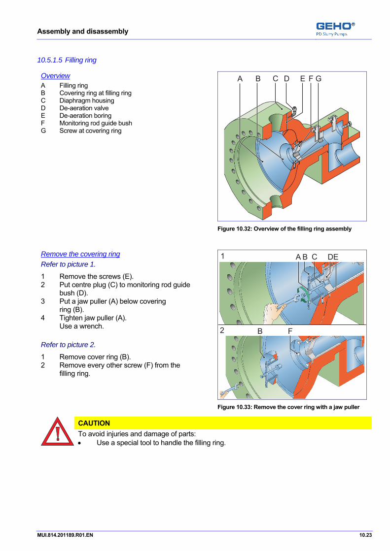
Assembly and disassembly
MUI.814.201189.R01.EN 10.23
Pos: 56.12 /GEHO/Heading/H4/Filling ring @ 1\mod_1165326308309_31.doc @ 9003
10.5.1.5 Filling ring Pos: 56.13 /GEHO/Assembly and Disassembly/Diaphragm housing unit/Filling Ring/Overview @ 1\mod_1165313193329_31.doc @ 8937
Overview A Filling ring B Covering ring at filling ring C Diaphragm housing D De-aeration valve E De-aeration boring F Monitoring rod guide bush G Screw at covering ring
ECA B GD F
Figure 10.32: Overview of the filling ring assembly
Pos: 56.14 /GEHO/Assembly and Disassembly/Diaphragm housing unit/Filling Ring/Remove the cover ring @ 1\mod_1165307507022_31.doc @ 8934
Remove the covering ring Refer to picture 1.
1 Remove the screws (E). 2 Put centre plug (C) to monitoring rod guide
bush (D). 3 Put a jaw puller (A) below covering
ring (B). 4 Tighten jaw puller (A).
Use a wrench. Refer to picture 2.
1 Remove cover ring (B). 2 Remove every other screw (F) from the
filling ring.
1
2
DCA B E
FB
Figure 10.33: Remove the cover ring with a jaw puller
Pos: 56.15 /GEHO/Assembly and Disassembly/Diaphragm housing unit/Filling Ring/Remove the filling ring @ 1\mod_1165316258091_31.doc @ 8940
CAUTION
To avoid injuries and damage of parts: • Use a special tool to handle the filling ring.
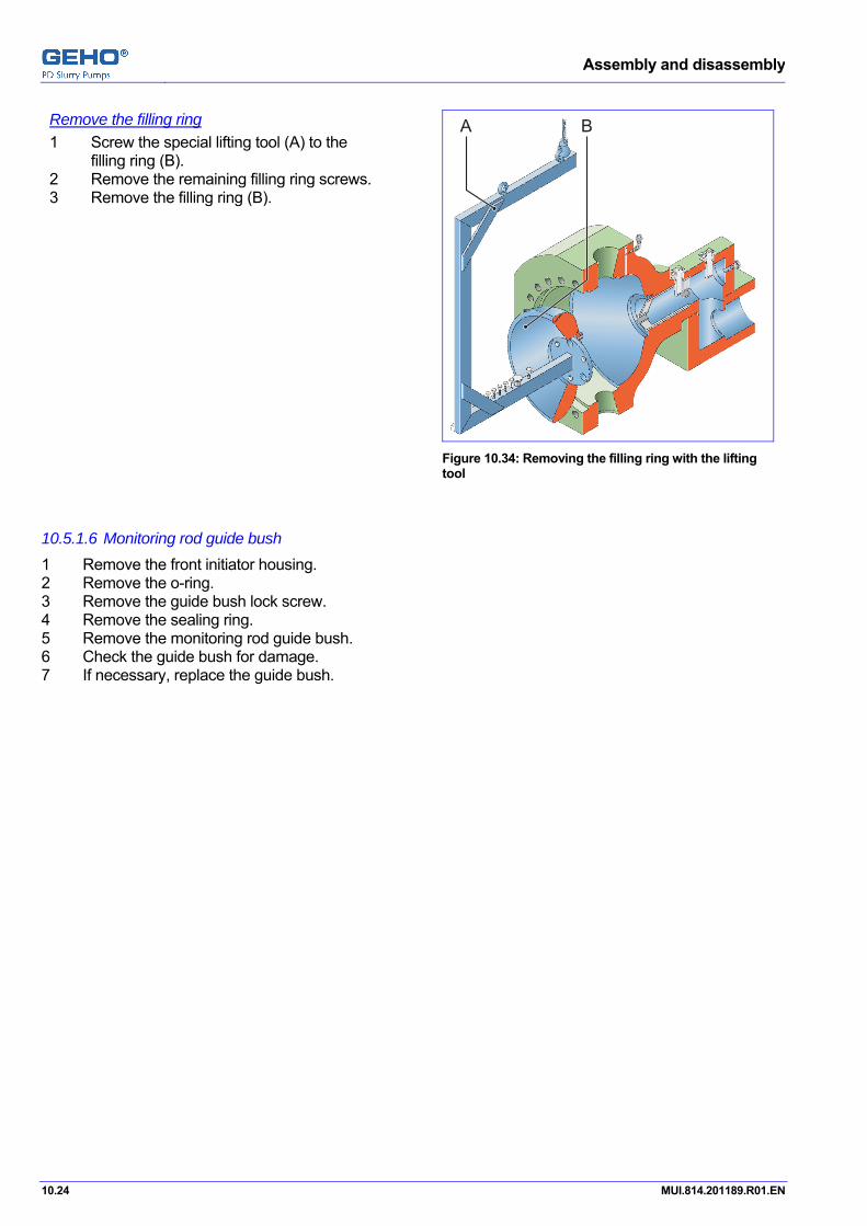
Assembly and disassembly
10.24 MUI.814.201189.R01.EN
Remove the filling ring 1 Screw the special lifting tool (A) to the
filling ring (B). 2 Remove the remaining filling ring screws. 3 Remove the filling ring (B).
A B
Figure 10.34: Removing the filling ring with the lifting tool
Pos: 56.16 /GEHO/Heading/H4/#.#.#.# Monitoring rod guide bush @ 1\mod_1165393535316_31.doc @ 9023
10.5.1.6 Monitoring rod guide bush Pos: 56.17 /GEHO/Assembly and Disassembly/Diaphragm housing unit/Guide bush/Remove @ 1\mod_1164897747510_31.doc @ 8875
1 Remove the front initiator housing. 2 Remove the o-ring. 3 Remove the guide bush lock screw. 4 Remove the sealing ring. 5 Remove the monitoring rod guide bush. 6 Check the guide bush for damage. 7 If necessary, replace the guide bush. Pos: 56.18 /--- Page break --- @ 0\mod_1136278659331_0.doc @ 766

Assembly and disassembly
MUI.814.201189.R01.EN 10.25
Pos: 56.19 /GEHO/Heading/H3/#.#.# Assembly @ 0\mod_1146735726056_31.doc @ 3610
10.5.2 Assembly Pos: 56.20 /GEHO/Heading/H4/#.#.#.# Diaphragm unit @ 1\mod_1165326645033_31.doc @ 9006
10.5.2.1 Diaphragm unit Pos: 56.21 /GEHO/Assembly and Disassembly/Diaphragm housing unit/Diaphragm/Closed, Standard/Assemble threated pin nofig @ 1\mod_1165320506364_31.doc @ 8950 Disassembl
1 Clean the thread of monitoring rod. 2 Clean the threaded pin of the diaphragm. 3 Apply a nut-lock (i.e. Loctite 243) to the threaded pin. 4 Screw the monitoring rod to the diaphragm unit. Refer to chapter "Special torques" for the correct torque.
Pos: 56.22 /GEHO/Heading/H4/#.#.#.# Monitoring rod guide bush @ 1\mod_1165393535316_31.doc @ 9023
10.5.2.2 Monitoring rod guide bush Pos: 56.23 /GEHO/Assembly and Disassembly/Diaphragm housing unit/Guide bush/Install @ 1\mod_1165322235178_31.doc @ 8992
1 Install the monitoring rod guide bush. 2 If necessary, then replace the o-ring. 3 Install the o-ring. 4 Install the front initiator housing. 5 If necessary, then replace the sealing ring. 6 Install the sealing ring. 7 Lock the guide bush lock screw. Pos: 56.24 /GEHO/Heading/H4/Filling ring @ 1\mod_1165326308309_31.doc @ 9003
10.5.2.3 Filling ring Pos: 56.25 /GEHO/Assembly and Disassembly/Diaphragm housing unit/Filling Ring/Install the filling ring @ 1\mod_1165392370371_31.doc @ 9021
CAUTION
To avoid injuries and damage of parts: • Use a special tool to handle the filling ring.
Install the filling ring 1 Clean the diaphragm housing. 2 Clean all de-aerating holes at the
diaphragm housing and filling ring and filling cover.
3 Put the filling ring (B) into the diaphragm housing. Use the special lifting tool.
4 Tighten the filling ring screws. 5 Remove the lifting tool (A). 6 Tighten the remaining filling ring screws.
A B
Figure 10.35: Install the filling ring with the lifting tool
Pos: 56.26 /GEHO/Assembly and Disassembly/Diaphragm housing unit/Filling Ring/Install the cover ring @ 1\mod_1165392147668_31.doc @ 9018
Install the covering ring 1 Put the cover ring into the filling ring. 2 Tighten the covering ring screws. Refer to "Technical data", "Special torques", for the correct torques. Pos: 56.27 /GEHO/Heading/H4/#.#.#.# Diaphragm @ 1\mod_1165394045801_31.doc @ 9030
Assembly and disassembly
10.26 MUI.814.201189.R01.EN
10.5.2.4 Diaphragm Pos: 56.28 /GEHO/Assembly and Disassembly/Diaphragm housing unit/Diaphragm unit/Hydraulic/Install @ 1\mod_1165321911048_31.doc @ 8969
Cleaning after diaphragm leakage or damage or contamination
ATTENTION After leakage of slurry into the propelling liquid camber, hard particles and chemical influences can result in corrosion and mechanical wear and damage. • Clean as soon as possible the propelling liquid system totally,
to avoid problems as a result of contamination. • Filling the propelling liquid system and the propelling liquid chamber with fresh propelling
liquid is the best way to preserve an "out of operation" system. Refer to the according chapter for the procedure of replacing the propelling liquid. Refer to chapter "Technical data" for the quality and quantity of the propelling liquid.
Draining and cleaning of the propelling liquid system: 1 Drain the propelling liquid system. 2 Open and inspect and clean the propelling liquid tank. 3 Clean the propelling liquid chamber, from the diaphragm opening up to the piston. 4 If applicable, remove and clean the "filling ring" in the diaphragm chamber. 5 Disconnect the propelling liquid lines, inspect them and flush the lines clean. 6 Open and inspect and clean the propelling liquid 2/2 valves at the inlet side and the outlet side. 7 Open and inspect and clean the non-return valves in the piping (near the 2/2 valves). Inspection and cleaning of the piston and liner: 8 Disassemble and inspect and clean the piston unit and its piston seals.
If necessary, then replace the piston seals. Inspect and clean the cylinder liner.
Refer to chapter "Assembly and disassembly", "Piston unit."
Draining and inspection and cleaning of the "Pressure limitation system":
WARNING
At normal conditions, the highest discharge operating pressure of the pump will remain in the piping of the "Pressure limitation system" between the pressure relieve valve and the non-return valves. • Always discharge the pressure in the piping, by opening the drain valve,
before working at it or at the connecting valves. 9 Open the drain valve and the vent valve at the piping between the pressure relieve valve and the non-
return valves. 10 If there is contamination in the propelling liquid,
then remove the piping and the open and inspect and clean the non-return valve. Refilling: 11 Replace the propelling liquid. 12 Replace all propelling liquid suction filters and discharge filters. 13 Re-fill the propelling liquid tank.
ATTENTION Remember at the priming phase to re-fill and de-aerate all the drained piping in the propelling liquid system and pressure limitation system.

Assembly and disassembly
MUI.814.201189.R01.EN 10.27
Diaphragm assembly 1 Clean the diaphragm area of the
diaphragm housing (A). 2 Grease the clamping edge (C) of the
diaphragm housing (A). ATTENTION Use only oil free grease.
3 Install the diaphragm (B) into the diaphragm housing (A).
A B C
Figure 10.36: Install the diaphragm unit
Pos: 56.29 /GEHO/Heading/H4/#.#.#.# Diaphragm housing cover @ 1\mod_1165393688115_31.doc @ 9026
10.5.2.5 Diaphragm housing cover Pos: 56.30 /GEHO/Assembly and Disassembly/Diaphragm housing unit/Diaphragm housing cover/Hydraulic/Install, Hoisting bracket @ 1\mod_1165323498290_31.doc @ 8998
Preparation 1 Check the diaphragm housing cover seal. 2 Replace the diaphragm housing cover
seal, if necessary. 3 Install the diaphragm housing cover seal. 4 Screw the push-off bolts back in 0-position. 5 Put the diaphragm housing cover to the
diaphragm housing. Use the diaphragm housing cover hoisting bracket.
6 Secure the diaphragm housing cover with four cover nuts. Use a wrench.
7 Screw evenly till the cover sits flat on the housing via its raised face (check for even clearance all around).
8 Remove the diaphragm housing cover hoisting bracket.
9 Tighten all other cover nuts hand-tight.
Figure 10.37: The diaphragm cover hoisting bracket
Pos: 56.31 /GEHO/Assembly and Disassembly/Diaphragm housing unit/Diaphragm housing cover/Hydraulic/Tighten @ 1\mod_1165323465060_31.doc @ 8995

Assembly and disassembly
10.28 MUI.814.201189.R01.EN
Hydraulic tension ring unit 1 Place the hydraulic tension ring unit (B) to
the stud bolts. Use a appropriate lifting device. Use the lifting eye (A).
2 Reset all hydraulic pistons: Push all hydraulic pistons at the tension ring down into the start-position (the pistons supports on the tension ring).
Check that the piston heads (B) are even with the surface of the tension ring unit (B).
3 Tighten the tension ring nuts (C). 4 Connect the hydraulic pump to the quick
release connector (E). 5 Fill the hydraulic tension ring (B) with oil
and de-aerate: • Loosen the blind plug (F). • Activate the Hydraulic pump until hydraulic oil leaks out. • Tighten the blind plug (F).
B
AF
D
C
E
Figure 10.38: Install the hydraulic tension ring unit
Tighten the cover nuts 1 Pressurize the hydraulic tension ring unit. Refer to "Technical data", "Special torques", "Diaphragm housing unit" for the procedure and torques and pressure.
2 Pre-tighten: Tighten all diaphragm housing cover nuts (D) with the pin (E) with normal hand force torque.
3 Release the pressure from the hydraulic tension ring unit, to allow settling of the surfaces.
4 Pressurize the hydraulic tension ring unit. Refer to "Technical data", "Special torques", "Diaphragm housing unit" for the procedure and torques and pressure.
5 Final-tighten: Tighten all diaphragm housing cover nuts (D) with the pin (E) with normal hand force torque.
Refer to "Technical data", "Special torques", "Diaphragm housing unit" for the procedure and torques and pressure.
6 Release the pressure from the hydraulic tension ring unit.
7 Remove the hydraulic pump. 8 Loosen the tension ring nuts (F). 9 Remove the hydraulic tension ring unit.
A B C D E F
Figure 10.39: Tighten the diaphragm cover nuts
Legend A Diaphragm housing cover B Hydraulic tension ring unit C Diaphragm housing cover stud bolt D Diaphragm housing cover nut E Pin (to turn the cover nut) F Tension ring nut
Pos: 57.1 /GEHO/Heading/H2/#.# Pulsation dampener @ 1\mod_1168952826922_31.doc @ 11788
Assembly and disassembly
MUI.814.201189.R01.EN 10.29
10.6 Pulsation dampener Pos: 57.2 /GEHO/Assembly and Disassembly/Pulsation damper/Safety instructions/Safety instructions pulsation dampener @ 1\mod_1168953439328_31.doc @ 11799
WARNING
The pre-charge pressure may never exceed the maximum allowable pressure, as indicated at the dampener identification plate.
WARNING
The dampener may be under pressure, even when the pressure gauge indicates no pressure. The pressure sensing opening may be clogged.
WARNING
In case of in-sufficient pre-charge pressure or nitrogen leakage, the pressure pulsations may be excessive and may cause heavy vibrations.
WARNING
• ONLY use nitrogen to pre-charge a dampener. • NEVER use oxygen, because of explosion danger.
WARNING
In case of an external fire, the nitrogen pressure inside the dampener will increase and may exceed the dampener design pressure.
WARNING
In case of a very rapid pressure drop in the discharge line, in combination with dis-location of the dampener diaphragm in relation to the dampener in/outlet opening, a diaphragm rupture might occur. In this case, the nitrogen can enter the slurry line and pressurize a blocked section of this slurry line or form a nitrogen “bubble” under pressure in the slurry line.
WARNING
• Prevent breathing in nitrogen. Escaping nitrogen may cause lack of oxygen.
WARNING
• Prevent breathing in nitrogen. If discharging the gas pressure through the valve, then the escaping nitrogen can push away the air in the direct environment, that can cause lack of oxygen.
Pos: 57.3 /--- Page break --- @ 0\mod_1136278659331_0.doc @ 766

Assembly and disassembly
10.30 MUI.814.201189.R01.EN
Pos: 57.4 /GEHO/Assembly and Disassembly/Pulsation damper/Disassembly @ 0\mod_1156236790706_31.doc @ 5737
10.6.1 Diaphragm removing 1 Strictly obey the pulsation dampener safety instructions. Refer to chapter "Pre-charging the discharge pulsation dampener".
2 Open the filler valve slowly, in many small steps, to discharge the nitrogen gas pressure from the pulsation dampener.
DANGER
Leaking nitrogen (N2) causes lack of oxygen: • Prevent breathing in nitrogen. • Be aware of the risk of suffocation, caused by to much nitrogen in the air. • Prevent nitrogen filling the working environment. • Assure in small rooms good ventilation, because of risks of nitrogen leakage. • Assure free escape routes, because of risks of nitrogen gas.
3 Make sure that the pulsation dampener is depressurized. 4 Loosen the cover nuts. DO NOT remove the cover nuts.
CAUTION
• Make sure that the pulsation dampener cover does not come upward against the nuts.
This indicates that pressure has not been completely discharged from the pulsation dampener.
5 Remove the pulsation dampener cover. Use the lifting eyes and a proper lifting device. ATTENTION
The lifting eyes on the pulsation dampener cover is only suitable for lifting the pulsation dampener unit.
6 Remove the old pulsation dampener diaphragm. 7 Inspect the interior of the pulsation dampener. 8 Clean the interior of the pulsation dampener. Pos: 57.5 /GEHO/Assembly and Disassembly/Pulsation damper/Assembly @ 0\mod_1156228349876_31.doc @ 5731
10.6.2 Diaphragm assembly 1 Clean the surface of the pulsation dampener
housing. 2 Clean the surface of the pulsation dampener
cover. 3 Make sure to remove all stains and remains
from the clamping edges for the diaphragm. 4 Apply a light coating of cup grease in the
diaphragm clamping edge.
CAUTION
Failure to properly lubricate these surfaces may result in a gradual leakage of nitrogen gas and drop of pre-charge pressure.
INFORMATION
• Use the grease Klüber Syntheso Pro AA2, article number 006025 to install the diaphragms,
O-rings and seals.

Assembly and disassembly
MUI.814.201189.R01.EN 10.31
10.6.2.1 Diaphragm folding, option 1 1 Push the cone outward.
2 Fold the diaphragm.
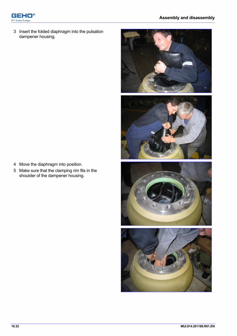
Assembly and disassembly
10.32 MUI.814.201189.R01.EN
3 Insert the folded diaphragm into the pulsation dampener housing.
4 Move the diaphragm into position. 5 Make sure that the clamping rim fits in the
shoulder of the dampener housing.

Assembly and disassembly
MUI.814.201189.R01.EN 10.33
10.6.2.2 Diaphragm folding, option 2 1 Fold the diaphragm.
2 Insert the diaphragm into the pulsation
dampener housing.

Assembly and disassembly
10.34 MUI.814.201189.R01.EN
3 Move the diaphragm into position. 4 Make sure that the clamping rim fits in the
shoulder of the dampener housing.
10.6.2.3 The correct position 1 Apply grease to the fitting edges of the cover. 2 Put the cover to the housing. 3 Tighten the nuts with the correct torque. Refer to chapter “Special torques”.
Pos: 58.1 /GEHO/Heading/H2/#.# Nitrogen filling device @ 1\mod_1169209240961_31.doc @ 11882
10.7 Nitrogen filling device Pos: 58.2 /GEHO/Assembly and Disassembly/Nitrogene filling device/Nitrogen filling device_dampemer+accu @ 1\mod_1169196110656_31.doc @ 11865
Use the nitrogen filling device for the filling of the pulsation dampener(s) and/or hydraulic accumulator(s). Refer to the document "Instrument list" for the correct pressure.
Refer to the chapter "Pre-charging the pulsation dampener" for correct filling of pulsation dampener(s) and/or hydraulic accumulator(s). Pos: 59.1 /GEHO/Heading/H2/#.# Frame unit @ 0\mod_1146735364754_31.doc @ 3598
10.8 Frame unit Pos: 59.2 /GEHO/General/Attention, Warning and Note/Information - Frame unit - Contact Weir Minerals @ 1\mod_1165496458248_31.doc @ 9075
INFORMATION
• For major maintenance work on the frame unit, please,
contact the service department of Weir Minerals Netherlands b.v. Pos: 60.1 /GEHO/Heading/H2/#.# Drive unit @ 0\mod_1134483988099_31.doc @ 452
10.9 Drive unit Pos: 60.2 /GEHO/Assembly and Disassembly/Drive unit/Disassembly and assembly @ 1\mod_1168951193156_31.doc @ 11775
ATTENTION
Refer to chapter "Catalogue information" for information about assembly and disassembly of drive unit parts.
Pos: 61 /--- Section break - Odd page --- @ 0\mod_1136277036628_0.doc @ 765

Appendix: Parts - Lists and drawings (pump section)
MUI.814.201189.R01.EN 11.1
Pos: 62 /GEHO/Heading/H1/#. Appendix: Parts - Lists and drawings (pump section) @ 1\mod_1169571543393_31.doc @ 11982
11 Appendix: Parts - Lists and drawings (pump section) Pos: 63 /GEHO/Parts lists/NOTE - Items with *** @ 1\mod_1165932498812_31.doc @ 9184
NOTE
When ordering items marked with *** specify the quantity.
Pos: 64 /GEHO/Parts lists/Pump/Project/201189 @ 5\mod_1225721529968_0.doc @ 40141
GEHO TZPM 1200 assembly Part list number 820.577.201189
Drawing number T.820.201189
ID Item number Description Technical details Qty005 818.080.559AU Puls.dampener filling unit 1
010 828.950.151M Lubrication unit 1
015 828.950.152M Flushing unit 1
020 828.950.153M Ventline unit 1
025 831.020.358D Valve unit 3
026 831.020.359D Valve unit 3
030 832.010.123Q Diaphragm housing unit 1
035 835.093.204C Piston unit 3
050 845.010.461M Frame unit 1
060 851.010.115N Pulsation dampener unit 1
065 853.010.251M Press.limit.regul.unit 1
070 855.010.054W Pressure transmitter unit 1
075 857.010.125M Propelling liquid unit 1
080 858.010.117M Electrical unit 1
085 895.577.213B Accessories 1
090 851.010.092Y Pulsation dampener unit 1
100 814.201189.16 Drive unit 1
110 814.201189.22 Compressor 1
910.150.052 Round head grooved pin D1476 r3x10 ss 20
795.000.400 Binding wire Ss ***
814.201189.25 Set of tagplates 1
818.030.258 Name plate-weir 5
915.020.008 Hexagon nut D934 m3 ss 12
913.310.052 Hex.socket head capscrew D84a m3x10 ss 12
818.030.140 Name plate-geho 2
910.150.031 Round head grooved pin D1476 r2x8 ss 6

Appendix: Parts - Lists and drawings (pump section)
11.2 MUI.814.201189.R01.EN
ID Item number Description Technical details Qty 818.030.272 Type plate Ss 1

Appendix: Parts - Lists and drawings (pump section)
MUI.814.201189.R01.EN 11.3
Puls.dampener filling unit Part list number 818.080.559AU
Drawing number T.818.080.199
ID Item number Description Technical details Qty001 922.595.211 Threaded reducing piece Red-r1/2/r1/4 1
002 922.985.253 Banjo coupl. w. one bolt P-rswv 6sr 1
003 913.003.138 Hex.socket head capscrew D912 m6x35 stl 6
004 929.050.503 Pipe clamp 106-pp 6
005 730.103.005 Tube R 6x1.5 ***
006 921.510.319 Pressure gauge R100/0-25000kpa 1
007 922.175.062 Male stud coupling Ges 12s/r1/2"-wd 1
008 922.135.062 Male connector Ges 12s/1/2npt 1
009 922.945.262 Stud standpipe adaptor Egesd 12s/r1/2-wd 2
010 922.075.209 Plug Vs-r1/4wd 2
011 913.003.248 Hex.socket head capscrew D912 m12x90 stl 2
012 855.100.065 Connecting block 1
013 818.030.026 Type plate 1
014 910.150.029 Round head grooved pin D1476 r2x5 1.4305 4
015 921.020.060 Valve G1/2"-pv4ps-ss 1
016 828.500.585 Adaptor 1
017 931.400.223 Sealing ring 22-27-1.5 din7603 1
018 922.945.253 Stud standpipe adaptor Egesd 6sr-wd 1
019 922.285.254 Bulkhead coupling P-gsv 6s 2
020 921.050.080 Needle valve 1/2"npt/b8-fxf 1
021 922.305.253 Equal elbow coupling P-wv 6s 1
022 922.175.253 Male stud coupling P-gev 6sr-wd 1
023 922.365.254 Bulk head elbow coupling P-wsv 6s 1
024 922.105.253 Straight coupling P-gv 6s 2
025 929.050.530 Locking sheet Dp1 6
026 828.500.586 Cover 1
027 931.031.205 O-ring R15x2.5 nbr-90sh 1

Appendix: Parts - Lists and drawings (pump section)
11.4 MUI.814.201189.R01.EN

Appendix: Parts - Lists and drawings (pump section)
MUI.814.201189.R01.EN 11.5
Lubrication unit Part list number 828.950.151M
Drawing number T.828.900.369
ID Item number Description Technical details Qty001 950.262.036 Electric motor 0.75kwn1500 1
002 960.010.625 Coupling Kd19-14/19 (stl 1
003 960.020.063 Gear pump (r Sf2/6 rd-12l 1
004 960.020.622 Lantern piece Sf2/dm80 1
005 816.940.974 Support 1
006 913.003.195 Hex.socket head capscrew D912 m10x20 stl 3
007 913.003.165 Hex.socket head capscrew D912 m8x20 stl 4
008 914.106.196 Hexagon screw D933 m10x25stl-glv 4
009 917.306.028 Lock washer D125a m10 stl-glv 4
010 921.700.832 Suction filter-element 0050s-125-wp 1
011 911.070.333 Stud D938 m16x40 stl 3
012 917.346.040 Lock washer D9021a m16 stl-glv 3
013 999.999.000 Arrow=rotating direction 1
014 910.150.029 Round head grooved pin D1476 r2x5 1.4305 2
015 921.510.187 Pressure gauge R100/0-1600kpa 1
019 928.860.027 Ball valve Sk3-28l25 1
020 814.201189.52 Filterhousing Ur219 1
021 814.201189.53 Element filtrans 1
030 929.050.500 Pipe clamp 112-pp 4
031 929.050.501 Pipe clamp 428-pp 6
032 929.050.530 Locking sheet Dp1 4
033 929.050.531 Locking sheet Dp4 16
034 914.003.144 Hexagon bolt D931 m6x65 stl 12
035 914.103.139 Hexagon bolt D933 m6 x40 stl 4
036 922.895.217 Stud standpipe adaptor Egesd 18l/1/2npt 2
037 925.780.610 Nipple 1/2"npt ss 1
038 922.285.219 Bulkhead coupling P-gsv 18l 1
039 816.941.074 Support 1.0067 1
040 868.001.879 Distance bushing 2
041 914.103.243 Hexagon screw D933 m12x60 stl 2
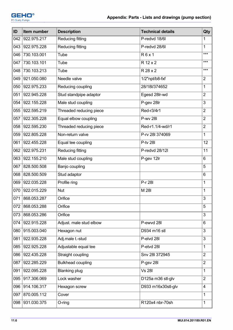
Appendix: Parts - Lists and drawings (pump section)
11.6 MUI.814.201189.R01.EN
ID Item number Description Technical details Qty042 922.975.217 Reducing fitting P-redvd 18/6l 1
043 922.975.228 Reducing fitting P-redvd 28/6l 1
046 730.103.001 Tube R 6 x 1 ***
047 730.103.101 Tube R 12 x 2 ***
048 730.103.213 Tube R 28 x 2 ***
049 921.050.080 Needle valve 1/2"npt/b8-fxf 2
050 922.975.233 Reducing coupling 28/18l/374652 1
051 922.945.228 Stud standpipe adaptor Egesd 28lr-wd 2
054 922.155.228 Male stud coupling P-gev 28lr 3
055 922.595.219 Threaded reducing piece Red-r3/4r1 2
057 922.305.228 Equal elbow coupling P-wv 28l 2
058 922.595.230 Threaded reducing piece Red-r1.1/4-wd/r1 2
059 922.805.228 Non-return valve P-rv 28l 374069 1
061 922.455.228 Equal tee coupling P-tv 28l 12
062 922.975.231 Reducing fitting P-redvd 28/12l 11
063 922.155.210 Male stud coupling P-gev 12lr 6
067 828.500.508 Banjo coupling 5
068 828.500.509 Stud adaptor 6
069 922.035.228 Profile ring P-r 28l 1
070 922.015.229 Nut M 28l 1
071 868.053.287 Orifice 3
072 868.053.288 Orifice 5
073 868.053.286 Orifice 3
074 922.915.228 Adjust. male stud elbow P-ewvd 28l 6
080 915.003.040 Hexagon nut D934 m16 stl 3
081 922.935.228 Adj.male t.-stud P-elvd 28l 3
085 922.925.228 Adjustable equal tee P-etvd 28l 1
086 922.435.228 Straight coupling Snv 28l 372945 2
087 922.285.229 Bulkhead coupling P-gsv 28l 2
091 922.095.228 Blanking plug Vs 28l 1
095 917.306.069 Lock washer D125a m36 stl-glv 2
096 914.106.317 Hexagon screw D933 m16x30stl-glv 4
097 870.005.112 Cover 1
098 931.030.375 O-ring R120x4 nbr-70sh 1

Appendix: Parts - Lists and drawings (pump section)
MUI.814.201189.R01.EN 11.7
ID Item number Description Technical details Qty100 971.600.008 Flow sensor 1
101 922.950.879 T-piece E40080/ql28-18-28 1
102 922.950.880 Adapter E40104 1
110 971.450.059 Pressure transmitter 1
120 971.050.020 Level switch Nivotemp m-350-2k8 1
121 853.100.583 Housing 1
122 828.500.563 Reducer 1
123 922.595.224 Threaded reducing piece Red-r1/r1/2 2
124 922.945.217 Stud standpipe adaptor Egesd 18lr-wd 2
125 922.155.217 Male stud coupling P-gev 18lr 2
126 922.075.235 Plug Vs-r1.1/4wd 1

Appendix: Parts - Lists and drawings (pump section)
11.8 MUI.814.201189.R01.EN

Appendix: Parts - Lists and drawings (pump section)
MUI.814.201189.R01.EN 11.9
Flushing unit Part list number 828.950.152M
Drawing number T.828.900.337
ID Item number Description Technical details Qty001 922.985.209 Banjo coupl. w. one bolt P-rswv 12l/r1/4 9
002 922.455.209 Equal tee coupling P-tv 12l 6
003 922.155.210 Male stud coupling P-gev 12lr 3
004 922.945.210 Stud standpipe adaptor Egesd 12lr-wd 3
005 922.975.220 Reducing fitting P-redvd 18/12l 3
006 730.103.108 Tube R 18 x 1.5 ***
007 922.455.217 Equal tee coupling P-tv 18l 2
008 922.305.217 Equal elbow coupling P-wv 18l 1
009 730.103.101 Tube R 12 x 2 ***
010 922.155.217 Male stud coupling P-gev 18lr 1
012 922.365.219 Bulkhead elbow coupling P-wsv 18l 1

Appendix: Parts - Lists and drawings (pump section)
11.10 MUI.814.201189.R01.EN

Appendix: Parts - Lists and drawings (pump section)
MUI.814.201189.R01.EN 11.11
Ventline unit Part list number 828.950.153M
Drawing number T.828.900.292
ID Item number Description Technical details Qty001 928.370.305 Banjo coupl.w. one bolt R3/8"- 8x6 1
002 770.528.000 Hose ***
003 928.130.005 Male connector Ack- 3/8"-6 4
004 922.945.210 Stud standpipe adaptor Egesd 12lr-wd 5
006 730.103.101 Tube R 12 x 2 ***
008 922.880.000 Non-return valve P-rv 12l(0.5 1
010 922.915.209 Adjust. male stud elbow P-ewvd 12l 2
013 928.120.008 Male connector 3/8" - 6 3
014 922.935.209 Adj.male stud t-stud b.t P-elvd 12l 3
015 922.285.210 Bulkhead coupling P-gsv 12l 2

Appendix: Parts - Lists and drawings (pump section)
11.12 MUI.814.201189.R01.EN

Appendix: Parts - Lists and drawings (pump section)
MUI.814.201189.R01.EN 11.13
Valve unit Part list number 831.020.358D
Drawing number T.831.000.460
ID Item number Description Technical details Qty001 023.582.018 Valve housing 1
003 025.582.016 Valve cover 1
010 831.350.259 Conical valve 1
011 831.700.925 Valve ring 1
012 831.150.918 Valve seat 1
013 831.900.051.14 Lock nut 1
014 825.107.043 Compression spring 1
015 831.900.889 Clamping piece 1
016 831.900.824 Guide bush 1
017 862.007.527 Stud bolt 4
018 831.900.715 Piston 4
019 831.900.717 Nut 1.7225v 4
020 831.900.716 Nut 1.0503kg 4
021 822.270.004.67 Sealing ring 1
022 931.208.200 Sealing ring B7a,228.6x266wn100 1
023 931.191.175 Sealing ring B7a,195x229wn101 1
024 862.050.191 Nut Nf m42 4
026 960.010.621 Adapter R1/4"xr1/4"-3000b 2
027 960.010.613 Connecting nipple R1/4"/2000 bar 2
038 931.030.409 O-ring R220x4 nbr70-sh 2
039 933.111.066 Rod seal S8-65-75 4
040 933.111.086 Rod seal S8-85-100 4
041 913.020.239 Hex socket head capscrew D912 m12x40 ss 4
042 914.300.040 Eye bolt D580 m16 1.0401 1
043 914.206.411 Hexagon screw D561a m20x120 stl 2
045 831.900.719 Spacer 1.0503n 1
046 913.020.251 Hex.socket head capscrew D912 m12x120 ss 4
050 862.007.528 Stud bolt 12
051 862.050.013.36 Nut 12
Appendix: Parts - Lists and drawings (pump section)
11.14 MUI.814.201189.R01.EN

Appendix: Parts - Lists and drawings (pump section)
MUI.814.201189.R01.EN 11.15
Valve unit Part list number 831.020.359D
Drawing number T.831.000.461
ID Item number Description Technical details Qty001 023.582.019 Valve housing 1
003 025.582.015 Valve cover 1
009 831.900.709 Valve support 1
010 831.350.259 Conical valve 1
011 831.700.925 Valve ring 1
012 831.150.918 Valve seat 1
013 831.900.051.14 Lock nut 1
014 825.107.043 Compression spring 1
015 831.900.890 Clamping piece 1
016 831.900.824 Guide bush 1
017 862.007.526 Stud bolt 4
018 831.900.715 Piston 4
019 831.900.717 Nut 1.7225v 4
020 831.900.716 Nut 1.0503kg 4
021 822.270.004.67 Sealing ring 1
024 931.191.175 Sealing ring B7a,195x229wn101 1
026 960.010.621 Adapter R1/4"xr1/4"-3000b 2
027 960.010.613 Connecting nipple R1/4"/2000 bar 2
028 931.400.361 Sealing ring 36-42-2 din7603 1
029 831.900.454 Plug 1
033 917.260.134 Clamping sleeve R6x16 din1481-rvs 1
038 931.030.409 O-ring R220x4 nbr70-sh 2
039 933.111.066 Rod seal S8-65-75 4
040 933.111.086 Rod seal S8-85-100 4
041 914.206.411 Hexagon screw D561a m20x120 stl 2
044 862.050.003.36 Nut 4
045 862.007.525 Stud bolt 4
047 831.900.714 Pin 1

Appendix: Parts - Lists and drawings (pump section)
11.16 MUI.814.201189.R01.EN

Appendix: Parts - Lists and drawings (pump section)
MUI.814.201189.R01.EN 11.17
Diaphragm housing unit Part list number 832.010.123Q
Drawing number T.832.000.177
ID Item number Description Technical details Qty002 039.577.005 Diaphragm housing cover 3
003 045.577.005 Diaphragm housing 3
004 832.100.885 Corner piece 1
005 832.100.886 Middle piece 1
006 832.100.887 Corner piece 1
007 832.100.738 Filling ring 3
008 832.100.739 Covering ring 3
012 862.005.143 Initiator housing 6
013 832.100.578 Cover 6
015 832.100.901 Monitoring rod 3
016 832.100.899 Clamping bush 3
019 824.070.013 Diaphragm 3
021 925.530.224 Hexagon head pipe plug G 1" din 910-5.8 3
022 922.085.217 Blanking end Vs-m18x1.5wd 2
030 822.700.010 Sealing ring 3
031 931.031.267 O-ring R55x3 nbr-90sh 6
034 822.190.010 Sealing ring 3
035 931.400.331 Sealing ring 33-39-2 din7603 3
037 862.007.435 Stud bolt 1.7225v 72
039 862.007.531 Stud bolt 48
042 862.007.045.36 Stud bolt 24
044 862.050.274 Nut 24
045 862.050.002.36 Nut 72
047 862.050.013.36 Nut 48
049 862.005.120 Coupling nut 6
050 914.103.321 Hexagon screw D933 m16x50 stl 24
052 914.223.459 Hexagon set screw D561b m24x200 stl 9
053 816.020.428 Protective cap 3
059 914.103.327 Hexagon screw D933 m16x80 stl 18
063 913.003.196 Hex.socket head capscrew D912 m10x25 stl 6
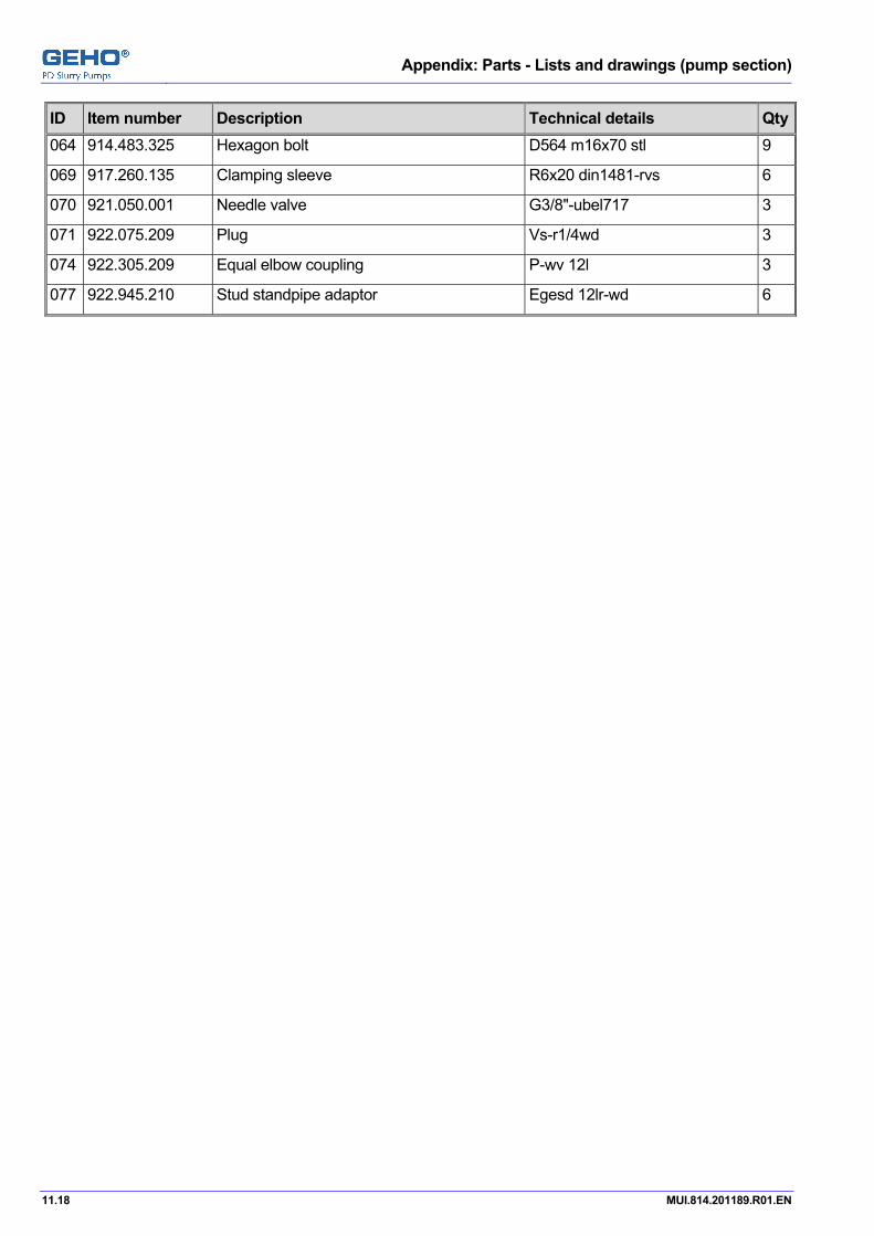
Appendix: Parts - Lists and drawings (pump section)
11.18 MUI.814.201189.R01.EN
ID Item number Description Technical details Qty064 914.483.325 Hexagon bolt D564 m16x70 stl 9
069 917.260.135 Clamping sleeve R6x20 din1481-rvs 6
070 921.050.001 Needle valve G3/8"-ubel717 3
071 922.075.209 Plug Vs-r1/4wd 3
074 922.305.209 Equal elbow coupling P-wv 12l 3
077 922.945.210 Stud standpipe adaptor Egesd 12lr-wd 6

Appendix: Parts - Lists and drawings (pump section)
MUI.814.201189.R01.EN 11.19
Piston unit Part list number 835.093.204C
Drawing number T.835.000.175
ID Item number Description Technical details Qty001 063.577.000 Piston rod 1
002 841.248.004 Cylinder liner 1
003 835.148.003 Piston body 1
004 835.348.004 Retaining plate 2
005 862.007.392 Stud bolt 8
006 862.050.112 Nut 8
007 841.900.341 Thrust piece 1
008 835.900.109 Sealing plate 1
009 931.031.452 O-ring R40.64x5.33 nbr-90 1
010 862.050.127 Nut Nf m48/d2510 1
011 914.103.242 Hexagon bolt D933 m12x55 stl 24
012 835.900.185 Guide ring 1
015 914.300.040 Eye bolt D580 m16 1.0401 1
020 933.160.211 Set of roof shaped rings L=33.5/ek 1
021 933.160.210 Set of roof shaped rings L=38.7/ek 1
022 822.270.045 Gasket R288-r309-1 1

Appendix: Parts - Lists and drawings (pump section)
11.20 MUI.814.201189.R01.EN
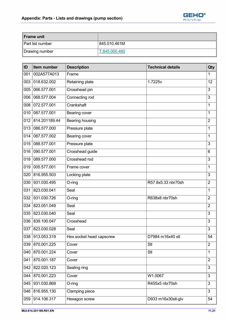
Appendix: Parts - Lists and drawings (pump section)
MUI.814.201189.R01.EN 11.21
Frame unit Part list number 845.010.461M
Drawing number T.845.000.480
ID Item number Description Technical details Qty001 002A577A013 Frame 1
003 018.632.002 Retaining plate 1.7225v 12
005 066.577.001 Crosshead pin 3
006 068.577.004 Connecting rod 3
008 072.577.001 Crankshaft 1
010 087.577.001 Bearing cover 1
012 814.201189.44 Bearing housing 2
013 086.577.000 Pressure plate 1
014 087.577.002 Bearing cover 1
015 088.577.001 Pressure plate 3
016 090.577.001 Crosshead guide 6
018 089.577.000 Crosshead rod 3
019 005.577.001 Frame cover 1
020 816.955.503 Locking plate 3
030 931.030.495 O-ring R57.8x5.33 nbr70sh 2
031 823.030.041 Seal 1
032 931.030.726 O-ring R638x8 nbr70sh 2
034 823.051.049 Seal 2
035 823.030.040 Seal 3
036 839.100.047 Crosshead 3
037 823.030.028 Seal 3
038 913.053.319 Hex.socket head capscrew D7984 m16x40 stl 54
039 870.001.225 Cover Stl 2
040 870.001.224 Cover Stl 1
041 870.001.187 Cover 2
042 822.020.123 Sealing ring 3
044 870.001.223 Cover W1.0067 3
045 931.030.869 O-ring R455x5 nbr70sh 3
046 816.955.130 Clamping piece 3
059 914.106.317 Hexagon screw D933 m16x30stl-glv 54

Appendix: Parts - Lists and drawings (pump section)
11.22 MUI.814.201189.R01.EN
ID Item number Description Technical details Qty062 914.236.529 Hexagon set screw D561a m30x2x100stl 4
063 914.003.449 Hexagon bolt D931 m24x100 stl 6
064 914.103.319 Hexagon screw D933 m16x40 stl 24
065 914.103.445 Hexagon screw D933 m24x70 stl 36
066 914.103.407 Hexagon screw D933 m20x80 stl 12
068 914.103.442 Hexagon screw D933 m24x55 stl 9
069 914.106.237 Hexagon screw D933 m12x30stl-glv 32
080 933.101.126 U-ring T20/125-145-16 3
081 933.021.125 Wiper ring 125-137-11nbr-90sh 3
082 911.040.441 Stud bolt D939 m24x50 8.8 18
084 914.103.317 Hexagon screw D933 m16x30 stl 6
085 915.006.055 Hexagon nut D934 m24 stl-glv 18
086 915.003.040 Hexagon nut D934 m16 stl 12
087 913.003.447 Hex.socket head capscrew D912 m24x80 stl 18
089 822.160.023 Sealing ring 3
091 846.100.172 Dust cover housing 3
092 846.100.126 Gasket holder 3
094 815.812.411 Flat bar steel 6
095 911.040.323 Stud bolt M16x60 din939-8.8 12
118 935.022.340 Lipseal Was 300-340-20 1
121 925.546.145 Hexagon head pipe plug 2
126 942.210.668 Spherial roller bearing 23168bk.mb 2
127 942.900.087 Cyl.roller bearing 3
128 942.900.074 Cyl.roller bearing 3
129 942.410.668 Pressure sleeve Ah3168h 2
131 922.155.211 Male stud coupling P-gew 12l/r1/2 6
132 730.103.103 Tube R 12 x 1.5 ***
134 925.720.284 Pipe nipple D2982 g2"x250 stl 1
136 921.150.021 Gate valve G2"-econ290a 1
138 948.790.002 Oilglass G2 2
140 921.700.033 Filter Pi 0114 mic 2
141 942.800.164 Lock nut Hm3164 1
142 816.955.504 Locking plate 1
143 925.016.114 Bend G3/4"-n1 1
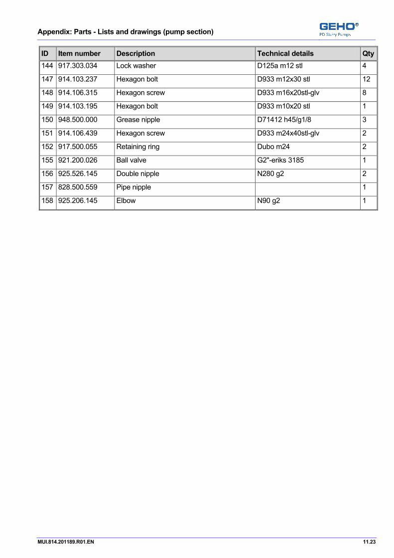
Appendix: Parts - Lists and drawings (pump section)
MUI.814.201189.R01.EN 11.23
ID Item number Description Technical details Qty144 917.303.034 Lock washer D125a m12 stl 4
147 914.103.237 Hexagon bolt D933 m12x30 stl 12
148 914.106.315 Hexagon screw D933 m16x20stl-glv 8
149 914.103.195 Hexagon bolt D933 m10x20 stl 1
150 948.500.000 Grease nipple D71412 h45/g1/8 3
151 914.106.439 Hexagon screw D933 m24x40stl-glv 2
152 917.500.055 Retaining ring Dubo m24 2
155 921.200.026 Ball valve G2"-eriks 3185 1
156 925.526.145 Double nipple N280 g2 2
157 828.500.559 Pipe nipple 1
158 925.206.145 Elbow N90 g2 1

Appendix: Parts - Lists and drawings (pump section)
11.24 MUI.814.201189.R01.EN

Appendix: Parts - Lists and drawings (pump section)
MUI.814.201189.R01.EN 11.25
Pulsation dampener unit Part list number 851.010.115N
Drawing number T.851.000.353
ID Item number Description Technical details Qty001 851.500.305 Cover 1
002 851.300.278 Pulsation dampener 1
006 824.030.000.64 Diaphragm 1
009 862.007.424 Stud bolt 12
010 922.075.218 Plug Vs-r1/2wd 1
011 931.030.575 O-ring R128x6 nbr-70sh 1
012 914.300.063 Ring bolt D580 m30 c15 1
013 862.005.353 Hexagon head screw 8
014 862.050.237 Nut Sa194-2h/m36 12
017 818.030.251 Type plate 1
018 818.030.210 Text plate 1
019 910.150.029 Round head grooved pin D1476 r2x5 1.4305 8
020 851.500.317 Flange 1
021 931.030.710 O-ring R132x8 nbr-70sh 1
022 822.150.021 Sealing ring 1
028 922.075.209 Plug Vs-r1/4wd 1

Appendix: Parts - Lists and drawings (pump section)
11.26 MUI.814.201189.R01.EN
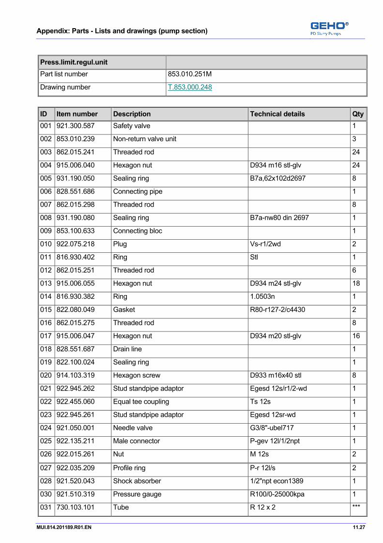
Appendix: Parts - Lists and drawings (pump section)
MUI.814.201189.R01.EN 11.27
Press.limit.regul.unit Part list number 853.010.251M
Drawing number T.853.000.248
ID Item number Description Technical details Qty001 921.300.587 Safety valve 1
002 853.010.239 Non-return valve unit 3
003 862.015.241 Threaded rod 24
004 915.006.040 Hexagon nut D934 m16 stl-glv 24
005 931.190.050 Sealing ring B7a,62x102d2697 8
006 828.551.686 Connecting pipe 1
007 862.015.298 Threaded rod 8
008 931.190.080 Sealing ring B7a-nw80 din 2697 1
009 853.100.633 Connecting bloc 1
010 922.075.218 Plug Vs-r1/2wd 2
011 816.930.402 Ring Stl 1
012 862.015.251 Threaded rod 6
013 915.006.055 Hexagon nut D934 m24 stl-glv 18
014 816.930.382 Ring 1.0503n 1
015 822.080.049 Gasket R80-r127-2/c4430 2
016 862.015.275 Threaded rod 8
017 915.006.047 Hexagon nut D934 m20 stl-glv 16
018 828.551.687 Drain line 1
019 822.100.024 Sealing ring 1
020 914.103.319 Hexagon screw D933 m16x40 stl 8
021 922.945.262 Stud standpipe adaptor Egesd 12s/r1/2-wd 1
022 922.455.060 Equal tee coupling Ts 12s 1
023 922.945.261 Stud standpipe adaptor Egesd 12sr-wd 1
024 921.050.001 Needle valve G3/8"-ubel717 1
025 922.135.211 Male connector P-gev 12l/1/2npt 1
026 922.015.261 Nut M 12s 2
027 922.035.209 Profile ring P-r 12l/s 2
028 921.520.043 Shock absorber 1/2"npt econ1389 1
030 921.510.319 Pressure gauge R100/0-25000kpa 1
031 730.103.101 Tube R 12 x 2 ***
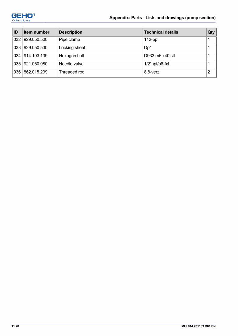
Appendix: Parts - Lists and drawings (pump section)
11.28 MUI.814.201189.R01.EN
ID Item number Description Technical details Qty032 929.050.500 Pipe clamp 112-pp 1
033 929.050.530 Locking sheet Dp1 1
034 914.103.139 Hexagon bolt D933 m6 x40 stl 1
035 921.050.080 Needle valve 1/2"npt/b8-fxf 1
036 862.015.239 Threaded rod 8.8-verz 2

Appendix: Parts - Lists and drawings (pump section)
MUI.814.201189.R01.EN 11.29
Non-return valve unit Part list number 853.010.239
Drawing number T.853.000.105
ID Item number Description Technical details Qty001 853.100.504 Valve housing 1
002 853.100.503 Valve guide 1
003 853.100.505 Valve 1
004 821.025.052 Ring 1
005 821.025.044 Ring 1
006 917.800.016 Compression spring R32xr2.5x71.5 1
007 913.006.135 Hex.socket head capscrew D912 m6x20 stl-glv 4
008 931.030.890 O-ring R70x3 1

Appendix: Parts - Lists and drawings (pump section)
11.30 MUI.814.201189.R01.EN

Appendix: Parts - Lists and drawings (pump section)
MUI.814.201189.R01.EN 11.31
Pressure transmitter unit Part list number 855.010.054W
Drawing number T.855.000.100
ID Item number Description Technical details Qty001 971.450.059 Pressure transmitter 2
002 971.450.063 Pressure transmitter 1
004 922.135.211 Male connector P-gev 12l/1/2npt 3
005 922.975.209 Reducing fitting P-redvd 12/6l 3
006 914.900.019 Hexagon screw 1/4"-20unc/l=1/2 6
007 921.050.080 Needle valve 1/2"npt/b8-fxf 3
008 925.780.610 Nipple 1/2"npt ss 3
009 816.941.166 Support 1
010 816.941.167 Support 1
011 914.106.135 Hexagon screw D933 m6x20 stl-glv 6
012 915.006.022 Hexagon nut D934 m6 stl-glv 6
013 922.915.200 Adjust. male stud elbow P-ewvd 6l 1
014 921.520.043 Shock absorber 1/2"npt econ1389 1

Appendix: Parts - Lists and drawings (pump section)
11.32 MUI.814.201189.R01.EN

Appendix: Parts - Lists and drawings (pump section)
MUI.814.201189.R01.EN 11.33
Propelling liquid unit Part list number 857.010.125M
Drawing number T.857.000.215
ID Item number Description Technical details Qty001 950.262.036 Electric motor 0.75kwn1500 1
002 960.010.625 Coupling Kd19-14/19 (stl 1
003 960.020.063 Gear pump (r Sf2/6 rd-12l 1
004 960.020.622 Lantern piece Sf2/dm80 1
005 816.940.742 Support 1.0067 1
006 913.003.195 Hex.socket head capscrew D912 m10x20 stl 3
007 913.003.165 Hex.socket head capscrew D912 m8x20 stl 4
008 914.103.196 Hexagon bolt D933 m10x25 stl 4
009 917.306.028 Lock washer D125a m10 stl-glv 12
010 911.070.236 Stud D938 m12x25 stl 2
011 917.306.034 Lock washer D125a m12 stl-glv 8
012 915.003.034 Hexagon nut D934 m12 stl 2
013 999.999.000 Arrow=rotating direction 1
014 910.150.029 Round head grooved pin D1476 r2x5 1.4305 2
015 922.155.217 Male stud coupling P-gev 18lr 2
016 922.595.218 Threaded reducing piece Red-r3/4/r1/2 3
018 922.915.209 Adjust. male stud elbow P-ewvd 12l 1
019 922.295.220 Straight reduct.coupling P-gv 18/12l 374536 1
020 814.201189.52 Filterhousing Ur219 1
021 814.201189.53 Element filtrans 1
022 922.595.228 Threaded reducing piece Red-r1.1/4/r1/2 2
023 922.945.217 Stud standpipe adaptor Egesd 18lr-wd 6
024 922.365.219 Bulkhead elbow coupling P-wsv 18l 1
025 922.915.217 Adjust. male stud elbow P-ewvd 18l 5
026 922.880.001 Non-return valve P-rv 18l(o.5 2
027 922.455.217 Equal tee coupling P-tv 18l 2
028 922.935.217 Adj.male t.-stud P-elvd 18l 3
029 922.975.220 Reducing fitting P-redvd 18/12l 2
030 922.285.219 Bulkhead coupling P-gsv 18l 2
032 922.915.060 Adjust. male stud elbow Ewsd 12s 2

Appendix: Parts - Lists and drawings (pump section)
11.34 MUI.814.201189.R01.EN
ID Item number Description Technical details Qty033 922.285.061 Bulkhead coupling Gss 12s 9
034 915.336.047 Hexagon nut D439 b-m20x1.5 2
035 922.945.210 Stud standpipe adaptor Egesd 12lr-wd 3
037 922.925.209 Adjustable equal tee P-etvd 12l 1
038 922.975.209 Reducing fitting P-redvd 12/6l 1
039 922.155.061 Male stud coupling Ges 12sr 6
040 814.201189.51 Hydr.accumulator 6l-330bar 1
041 917.306.025 Lock washer D125a m8 stl-glv 2
042 914.103.164 Hexagon bolt D933 m8x16 stl 6
049 971.400.045 Silencer R1/4 8
050 972.200.065 3/2 way valve Nw6-24vdc-no 6
055 972.200.066 3/2 way valve Nw6-24vdc-nc 2
056 972.900.000 Mounting block R3/'8"-r1/4"-n=8 1
057 925.470.209 Double nipple N245 g1/2"x3/8"stl 1
058 925.206.110 Elbow N90 g1/2" mall.ci 1
059 914.106.132 Hexagon screw D933 m6x10 stl-glv 4
060 921.510.187 Pressure gauge R100/0-1600kpa 1
061 922.135.211 Male connector P-gev 12l/1/2npt 1
062 922.035.209 Profile ring P-r 12l/s 24
063 922.015.261 Nut M 12s 24
064 921.050.080 Needle valve 1/2"npt/b8-fxf 1
065 921.510.223 Pressure gauge R63/0-1600kpa 1
066 922.135.209 Male connector 12l 1/4npt 373031 1
067 929.050.500 Pipe clamp 112-pp 1
068 929.050.530 Locking sheet Dp1 1
069 914.103.139 Hexagon bolt D933 m6 x40 stl 1
070 853.010.250 Prop.liquid/flush.unit 1
071 928.370.304 Banjo coupl. w.one bolt R1/4"- 8x6 8
072 770.528.000 Hose ***
073 922.075.213 Plug Vs-r3/8wd 4
074 931.400.183 Sealing ring 18-22-1.5 din7603 3
075 914.106.198 Hexagon screw D933 m10x35stl-glv 8
076 921.050.081 Needle valve 1/4"npt/b8-fxf 1
077 922.975.217 Reducing fitting P-redvd 18/6l 1
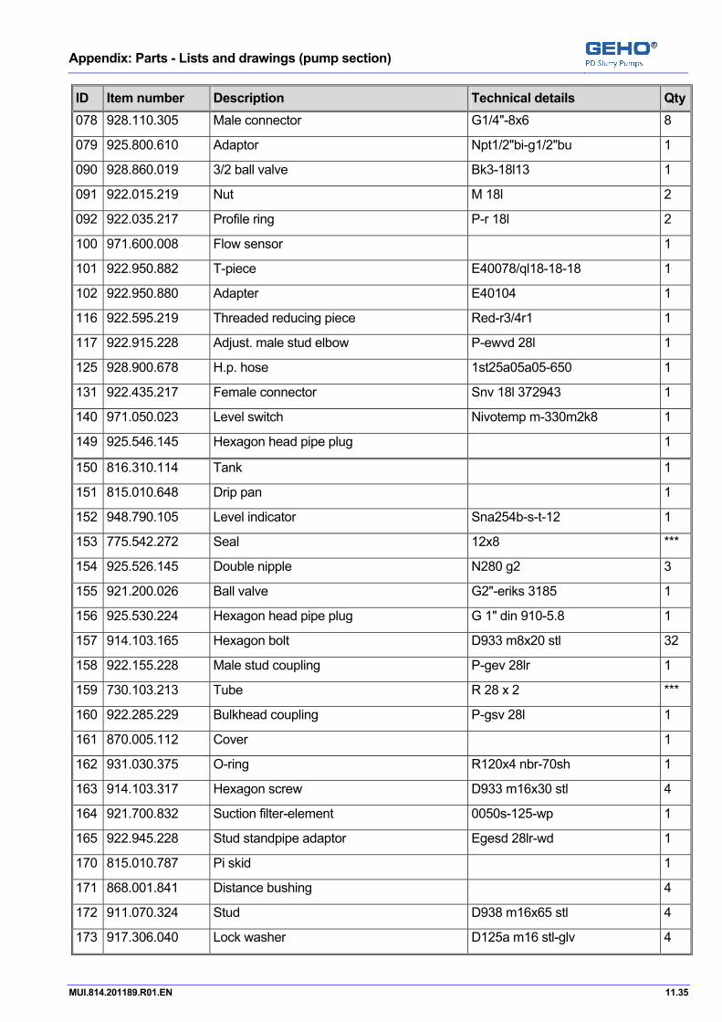
Appendix: Parts - Lists and drawings (pump section)
MUI.814.201189.R01.EN 11.35
ID Item number Description Technical details Qty078 928.110.305 Male connector G1/4"-8x6 8
079 925.800.610 Adaptor Npt1/2"bi-g1/2"bu 1
090 928.860.019 3/2 ball valve Bk3-18l13 1
091 922.015.219 Nut M 18l 2
092 922.035.217 Profile ring P-r 18l 2
100 971.600.008 Flow sensor 1
101 922.950.882 T-piece E40078/ql18-18-18 1
102 922.950.880 Adapter E40104 1
116 922.595.219 Threaded reducing piece Red-r3/4r1 1
117 922.915.228 Adjust. male stud elbow P-ewvd 28l 1
125 928.900.678 H.p. hose 1st25a05a05-650 1
131 922.435.217 Female connector Snv 18l 372943 1
140 971.050.023 Level switch Nivotemp m-330m2k8 1
149 925.546.145 Hexagon head pipe plug 1
150 816.310.114 Tank 1
151 815.010.648 Drip pan 1
152 948.790.105 Level indicator Sna254b-s-t-12 1
153 775.542.272 Seal 12x8 ***
154 925.526.145 Double nipple N280 g2 3
155 921.200.026 Ball valve G2"-eriks 3185 1
156 925.530.224 Hexagon head pipe plug G 1" din 910-5.8 1
157 914.103.165 Hexagon bolt D933 m8x20 stl 32
158 922.155.228 Male stud coupling P-gev 28lr 1
159 730.103.213 Tube R 28 x 2 ***
160 922.285.229 Bulkhead coupling P-gsv 28l 1
161 870.005.112 Cover 1
162 931.030.375 O-ring R120x4 nbr-70sh 1
163 914.103.317 Hexagon screw D933 m16x30 stl 4
164 921.700.832 Suction filter-element 0050s-125-wp 1
165 922.945.228 Stud standpipe adaptor Egesd 28lr-wd 1
170 815.010.787 Pi skid 1
171 868.001.841 Distance bushing 4
172 911.070.324 Stud D938 m16x65 stl 4
173 917.306.040 Lock washer D125a m16 stl-glv 4

Appendix: Parts - Lists and drawings (pump section)
11.36 MUI.814.201189.R01.EN
ID Item number Description Technical details Qty174 816.940.820 Support 2
175 915.003.040 Hexagon nut D934 m16 stl 4
176 914.300.040 Eye bolt D580 m16 1.0401 2
177 914.103.236 Hexagon bolt D933 m12x25 stl 8
180 770.556.578 Hose Tw50-nbr/cr-s ***
181 929.000.531 Hose band clamp S62/20skz 2
182 929.300.020 Connecting piece G2"/633-f/ss 2
183 929.300.000 Coupling G2"/633-c/ss 2
185 925.206.145 Elbow N90 g2 2
186 917.950.030 Bolt adapter M16-glv 4
191 730.103.108 Tube R 18 x 1.5 ***
193 730.103.001 Tube R 6 x 1 ***
194 730.103.101 Tube R 12 x 2 ***
195 814.201189.50 Pipe R28x2/l=500 1
210 816.020.474 Protection cover 1
211 911.170.325 Hexagon socket set screw 1
212 915.020.040 Hexagon nut D934 m16 1.4301 2
213 917.850.040 Lock washer D125b m16 ss 2
214 917.040.040 Spring washer B16 d127b-w1.4401 1
250 770.558.317 Hose R35-r25 ***
251 922.105.228 Straight coupling P-gv 28l 1
252 922.950.948 Female metric 1
253 922.950.949 Female swept elbow 1
254 929.000.012 Clamp 2
255 922.985.228 Banjo coupl. w. one bolt P-rswv 28lr 2
256 929.050.501 Pipe clamp 428-pp 1
257 929.050.531 Locking sheet Dp4 4
258 914.003.144 Hexagon bolt D931 m6x65 stl 2

Appendix: Parts - Lists and drawings (pump section)
MUI.814.201189.R01.EN 11.37
Prop.liquid/flush.unit Part list number 853.010.250
Drawing number T.853.000.240
ID Item number Description Technical details Qty001 853.010.241 2/2 way valve 7
002 853.100.329 Valve seat 7
003 853.100.455 Non-return valve 3
004 931.032.051 O-ring R21x1.5 fpm-80sh 11
005 853.100.525 Distributor block 1
006 862.005.314 Banjo bolt 4
007 931.082.021 Multiseal Scpp45-d 7
008 853.100.323 Base plate 3
009 853.100.330 Plug 3
010 913.003.169 Hex.socket head capscrew D912 m8x40 stl 32
012 822.030.024 Sealing ring 8
014 853.010.243 2/2 way valve 1
015 853.100.535 Distributor block 1
016 862.005.396 Banjo bolt 3
017 853.100.520 Bottom plate 1
018 853.100.518 Plug 1
019 853.100.519 Valve seat 1
020 853.100.517 Valve 1
021 931.082.017 Multiseal Scpp45-c 7

Appendix: Parts - Lists and drawings (pump section)
11.38 MUI.814.201189.R01.EN

Appendix: Parts - Lists and drawings (pump section)
MUI.814.201189.R01.EN 11.39
2/2 way valve Part list number 853.010.241
Drawing number T.853.000.068
ID Item number Description Technical details Qty001 853.100.387 Slide bearing 1
002 921.700.030 Filter G1/4"-lo.0304-01 1
003 853.100.490 Cover 1
004 853.100.216.64 Dampening 1
005 933.500.001 Diaphragm Bfa70/60-40 1
007 913.003.168 Hex.socket head capscrew D912 m8x35 stl 4
008 853.100.385 Valve housing 1
009 825.102.000.32 Compression spring 1
011 853.100.388 Slide bearing 1
012 917.403.030 Retaining ring D472 r30x1.2 ss 1
013 933.107.023 U-ring 20-30-8 1
014 853.100.391 Valve spindle 1

Appendix: Parts - Lists and drawings (pump section)
11.40 MUI.814.201189.R01.EN

Appendix: Parts - Lists and drawings (pump section)
MUI.814.201189.R01.EN 11.41
2/2 way valve Part list number 853.010.243
Drawing number T.853.000.110
ID Item number Description Technical details Qty001 853.100.387 Slide bearing 1
002 921.700.030 Filter G1/4"-lo.0304-01 1
003 853.100.490 Cover 1
004 853.100.216.64 Dampening 1
005 933.500.001 Diaphragm Bfa70/60-40 1
007 913.003.168 Hex.socket head capscrew D912 m8x35 stl 4
008 853.100.385 Valve housing 1
009 825.102.000.32 Compression spring 1
011 853.100.388 Slide bearing 1
012 917.403.030 Retaining ring D472 r30x1.2 ss 1
013 933.107.023 U-ring 20-30-8 1
014 853.100.522 Valve spindle 1

Appendix: Parts - Lists and drawings (pump section)
11.42 MUI.814.201189.R01.EN

Appendix: Parts - Lists and drawings (pump section)
MUI.814.201189.R01.EN 11.43
Electrical unit Part list number 858.010.117M
Drawing number T.814.201189.43
ID Item number Description Technical details Qty001 814.201189.41 Control box cpl 1
001 814.201189.34 Memory card 1
001 814.201189.37 Hmi-panel 1
002 814.201189.40 Terminal box 1
003 814.201189.42 Terminal box 1
004 913.306.074 Hex.socket head capscrew D84a m4x16 stl-glv 4
005 858.100.250 Initiator 6
006 931.080.085 U-seal 8.5-13.4-1.0 4
007 913.400.165 Hex.socket head capscrew D912 m8x20 1.4401 4
008 915.140.025 Hexagon nut D934 m8 ss 4
009 917.280.025 Lock washer D125a m8 ss 4
010 858.101.005 Cable channel 1
011 914.103.316 Hexagon screw D933 m16x25 stl 4
012 995.025.023 Bend Pg13 h318 6
013 995.001.050 Hose swivel Pg 13 12
014 790.000.014 Protection sleeve Ins.ro.14.5 ***
015 995.006.202 Reducing ring Pg11-pg9 h527 3
016 790.000.009 Protection sleeve R10 ***
017 995.025.021 Bend Pg9 h318 4
018 995.001.052 Hose swivel Pg 9 4
019 795.000.448 Cable Oelflex 3x1 mm2 ***
020 995.000.063 Lock nut Pg11 4
021 795.000.461 Cable ***
022 730.103.202 Tube R 22 x 2 ***
023 929.050.502 Pipe clamp 322-pp 6
024 858.100.263 Cable channel Stl 1
025 914.106.197 Hexagon screw D933 m10x30stl-glv 8
026 914.106.141 Hexagon bolt D933 m6x50 14
027 929.050.532 Locking sheet Dp3 6
028 816.941.141 Support 1

Appendix: Parts - Lists and drawings (pump section)
11.44 MUI.814.201189.R01.EN
ID Item number Description Technical details Qty029 971.100.055 Initiator Ni12u-em18-ap6x 1
030 868.005.006 Detector piece 1
031 929.000.917 Clamping ring Stl-glv 1
032 911.040.321 Stud bolt M16x50 din939-8.8 2
033 914.103.317 Hexagon screw D933 m16x30 stl 2
034 917.306.022 Lock washer D125a m6 stl-glv 2
035 995.001.086 Cable gland 1
036 995.000.162 Lock nut M16x1.5 1
037 816.941.275 Support 1
038 862.050.279 Hexagon support 2
040 995.040.010 Cable tierap T 50 r 100
041 995.040.012 Cable tierap 4x140 / nylon 6.6 100
043 790.000.013 Protection sleeve ***
044 858.100.261 Cable channel Stl 1
045 858.100.262 Cable channel Stl 1
047 917.306.028 Lock washer D125a m10 stl-glv 8
048 795.000.449 Cable ***
049 995.006.421 Adapter M20x1.5/pg9 1
050 795.000.445 Cable Oelflex 2x0.75 mm2 ***
051 995.006.422 Adapter 3
052 995.025.022 Bend Pg11 4

Appendix: Parts - Lists and drawings (pump section)
MUI.814.201189.R01.EN 11.45
Accessories Part list number 895.577.213B
Drawing number T.895.577.009
ID Item number Description Technical details Qty001 815.010.780 Base frame 1
002 828.551.977 Pressure pipe 1
003 828.551.975 Suction line 1
004 828.551.970 Support 1
005 828.551.781 Support 1
006 828.500.554 Plug 1
007 931.400.640 Sealing ring 64-72-2.5 d7603 2
008 911.040.609 Stud bolt D939 m36x100-8.8 8
009 915.003.069 Hexagon nut D934 m36 stl 8
010 828.500.548 Plug 1
011 828.551.378 Support 1.0570n 1
012 913.003.443 Hex.socket head capscrew D912 m24x60 stl 8
013 931.190.100 Sealing ring B7a-nw100 din2697 1
014 815.010.782 Support 1
015 816.941.121 Support 1
016 816.941.291 Support 2
017 927.026.200 Blind flange 8"rf-900lbs stl 1
018 931.208.200 Sealing ring B7a,228.6x266wn100 3
019 862.007.255 Reducing shank bolt 12
020 915.040.069 Hexagon nut Nf m36 din2510 48
021 862.007.381 Stud bolt 24
022 927.020.250 Flange 10"rf / 150lbs 1
023 822.250.011 Sealing ring 2
024 914.003.448 Hexagon bolt D931 m24x90 stl 12
025 915.003.055 Hexagon nut D934 m24 stl 24
026 914.103.444 Hexagon screw D933 m24x65 stl 12
027 911.040.444 Stud bolt M24x65 din939-8.8 12
029 822.200.059 Sealing ring R270-r204-2 3
030 914.103.439 Hexagon screw D933 m24x40 stl 12
031 816.930.437 Shim 3

Appendix: Parts - Lists and drawings (pump section)
11.46 MUI.814.201189.R01.EN
ID Item number Description Technical details Qty032 914.103.443 Hexagon screw D933 m24x60 stl 42
033 914.103.403 Hexagon screw D933 m20x60 stl 12
034 816.930.484 Shim 6
035 914.236.529 Hexagon set screw D561a m30x2x100stl 8
036 911.170.325 Hexagon socket set screw 2
037 915.020.040 Hexagon nut D934 m16 1.4301 4
038 917.280.040 Lock washer D125a m16 1.4401 4
039 917.040.040 Spring washer B16 d127b-w1.4401 2

Appendix: Parts - Lists and drawings (pump section)
MUI.814.201189.R01.EN 11.47
Pulsation dampener unit Part list number 851.010.092Y
Drawing number T.851.000.393
ID Item number Description Technical details Qty001 851.500.203 Cover 1
002 851.300.230 Pulsation dampener body 1
003 824.030.000.64 Diaphragm 1
007 921.020.060 Valve G1/2"-pv4ps-ss 1
008 921.510.184 Pressure gauge R100-0-1000kpa 1
009 862.007.389 Stud bolt 12
012 914.300.055 Eye bolt D580 m24 1.0401 1
014 862.050.227 Nut Sa194-2h/m30 12
017 818.030.271 Type plate Ss 1
018 818.030.210 Text plate 1
019 910.150.029 Round head grooved pin D1476 r2x5 1.4305 8
022 931.210.100 Sealing ring Wl-nw100-nd40 1
023 828.500.585 Adaptor 1
024 922.945.262 Stud standpipe adaptor Egesd 12s/r1/2-wd 2
025 922.755.062 Manometer coupling Mas 12sr 1
028 922.075.209 Plug Vs-r1/4wd 1
029 922.155.062 Male stud coupling Ges 12s/r1/2 1
030 931.400.223 Sealing ring 22-27-1.5 din7603 1
031 828.500.586 Cover 1
032 931.031.205 O-ring R15x2.5 nbr-90sh 1

Appendix: Parts - Lists and drawings (pump section)
11.48 MUI.814.201189.R01.EN

Appendix: Parts - Lists and drawings (pump section)
MUI.814.201189.R01.EN 11.49
Drive unit Part list number 814.201189.16
Drawing number T.814.201189.16
ID Item number Description Technical details Qty001 814.201189.31 Gear box 1
002 814.201189.32 Flex.coupling 1
003 814.201189.33 Gear coupling 1
004 814.201189.30 Electric motor 1100kwn1488 1
005 816.020.593 Protective cap 1
006 816.020.578 Protective cap 1
007 815.010.793 Base frame 1
008 816.900.492 Shim 4
009 816.930.489 Shim 4
010 816.930.490 Shim 2
011 914.106.197 Hexagon screw D933 m10x30stl-glv 4
012 917.306.028 Lock washer D125a m10 stl-glv 8
013 915.006.028 Hexagon nut D934 m10 stl-glv 4
014 917.306.069 Lock washer D125a m36 stl-glv 10
015 914.006.611 Hexagon bolt D931m36x120stl-glv 4
016 914.006.612 Hexagon bolt D931m36x130stl-glv 6
017 914.206.328 Hexagon bolt D561am16x90stl-glv 12
018 914.236.533 Hexagon set screw M30x2x140 d561a-st 8
019 911.170.325 Hexagon socket set screw 2
020 915.020.040 Hexagon nut D934 m16 1.4301 4
021 917.280.040 Lock washer D125a m16 1.4401 4
022 917.040.040 Spring washer B16 d127b-w1.4401 2
023 914.106.195 Hexagon screw D933 m10x20stl-glv 4

Appendix: Parts - Lists and drawings (pump section)
11.50 MUI.814.201189.R01.EN
Pos: 65 /--- Section break - Odd page --- @ 0\mod_1136277036628_0.doc @ 765

Appendix: Parts - Lists and drawings (special tools)
MUI.814.201189.R01.EN 12.1
Pos: 66 /GEHO/Heading/H1/#. Appendix: Parts - Lists and drawings (special tools) @ 1\mod_1169571568190_31.doc @ 11986
12 Appendix: Parts - Lists and drawings (special tools) Pos: 67 /GEHO/Parts lists/NOTE - Items with *** @ 1\mod_1165932498812_31.doc @ 9184
NOTE
When ordering items marked with *** specify the quantity.
Pos: 68 /GEHO/Parts lists/Special tools/Project/814.201189.10 @ 5\mod_1226306477587_0.doc @ 40301
Set of tools Part list number 814.201189.10
Drawing number
ID Item number Description Technical details Qty001 897.050.241 Pulling device cil.liner 1
002 897.010.583J Hydr.tension ring-unit 1
003 897.010.633H Fill.ring lifting device 1
004 897.050.127 Ass.valve seal tool Api-11 1
005 897.010.635 Tool valve nut 1
006 897.050.279 Collect chuck Stl 1
007 897.010.706 Lifting bar unit 1
008 897.050.345 Disass.tool guide bush 1
009 897.010.606L Disass.valve seat tool 1
010 897.010.710 Hydr.pump-unit 1
011 897.010.588R Lifting cover 1
012 897.010.680F Hoisting unit 1
013 897.010.685BJ Accumul.filling device 1
014 980.622.915 Socket wrench 1
015 980.627.097 Socket 32/sl.w.36 1
016 ELA.000.593 Coversheet 1
017 ELA.000.594 Key Rittal 1

Appendix: Parts - Lists and drawings (special tools)
12.2 MUI.814.201189.R01.EN

Appendix: Parts - Lists and drawings (special tools)
MUI.814.201189.R01.EN 12.3
Hydr.tension ring-unit Part list number 897.010.583J
Drawing number T.897.000.296
ID Item number Description Technical details Qty001 897.100.982 Tension ring 1.7225v 1
002 853.200.514 Clamping bush 24
003 862.050.005.36 Nut 24
004 933.111.065 Rod seal S8-65 24
005 933.111.093 Rod seal Iso-90 24
006 914.300.047 Eye bolt D580 m20 1.0401 1
007 960.010.621 Adapter R1/4"xr1/4"-3000b 1
008 960.010.613 Connecting nipple R1/4"/2000 bar 1
011 960.010.624 Blind plug 1
013 897.100.932 Pin 1

Appendix: Parts - Lists and drawings (special tools)
12.4 MUI.814.201189.R01.EN

Appendix: Parts - Lists and drawings (special tools)
MUI.814.201189.R01.EN 12.5
Fill.ring lifting device Part list number 897.010.633H
Drawing number T.897.000.244
ID Item number Description Technical details Qty001 897.050.343 Lifting device 1
002 897.100.808 T-nut 1
003 914.300.047 Eye bolt D580 m20 1.0401 1
004 862.005.319 Boulon 3
005 917.276.047 Lock washer M20 d7349-st-verz 1
006 914.003.323 Hexagon bolt D931 m16x60 stl 3
007 897.100.819 Plug 1
008 914.003.251 Hexagon bolt D931 m12x120 1
009 915.350.034 Lifting eye nut M12 din582-c15 1

Appendix: Parts - Lists and drawings (special tools)
12.6 MUI.814.201189.R01.EN

Appendix: Parts - Lists and drawings (special tools)
MUI.814.201189.R01.EN 12.7
Tool valve nut Part list number 897.010.635
Drawing number T.897.000.233
ID Item number Description Technical details Qty001 897.050.222 Valve nut wrench 1
002 897.100.823 Pin 3
003 914.106.237 Hexagon screw D933 m12x30stl-glv 3
004 917.306.034 Lock washer D125a m12 stl-glv 3
005 897.100.824 Pipe 1

Appendix: Parts - Lists and drawings (special tools)
12.8 MUI.814.201189.R01.EN

Appendix: Parts - Lists and drawings (special tools)
MUI.814.201189.R01.EN 12.9
Lifting bar unit Part list number 897.010.706
Drawing number T.897.000.241
ID Item number Description Technical details Qty001 897.101.010 Lifting spindle 1
002 897.100.849 Ring 1
003 914.300.034 Eye bolt D580 m12 stl 1
004 911.040.441 Stud bolt D939 m24x50 8.8 1
005 914.206.239 Hexagon screw D561am12x40stl-glv 2

Appendix: Parts - Lists and drawings (special tools)
12.10 MUI.814.201189.R01.EN

Appendix: Parts - Lists and drawings (special tools)
MUI.814.201189.R01.EN 12.11
Disass.valve seat tool Part list number 897.010.606L
Drawing number T.897.000.293
ID Item number Description Technical details Qty001 897.100.867 Drawing operation 1
002 897.101.099 Connecting rod 1
003 897.100.950 Block 1.0570 1
004 853.200.528 Clamping bush 1
005 853.200.529 Clamping bush 1
006 933.111.060 Rod seal S8-60 1
007 933.111.045 Rod seal S8-45 1
008 960.010.613 Connecting nipple R1/4"/2000 bar 1
009 960.010.621 Adapter R1/4"xr1/4"-3000b 1
010 915.003.063 Hexagon nut D934 m30 stl 2
011 897.100.951 Flat bar steel 1.0067 2
012 913.356.132 Hex.socket head capscrew D85a m6x10 stl-glv 4
013 897.100.752 Block 1
014 897.101.101 Connecting rod 1
015 897.100.753 Flat bar 2
016 897.100.788 Block 1.7225v 1
017 897.100.754 Contra-block 1
018 897.100.755 Threaded rod M30x320 1

Appendix: Parts - Lists and drawings (special tools)
12.12 MUI.814.201189.R01.EN

Appendix: Parts - Lists and drawings (special tools)
MUI.814.201189.R01.EN 12.13
Hydr.pump-unit Part list number 897.010.710
Drawing number T.897.000.318
ID Item number Description Technical details Qty001 960.010.036 Hydraulic pump Hf-b225/0-2000bar 1
002 960.010.623 Adapter 1/4"bsp/9/16"-18un 1
003 960.010.613 Connecting nipple R1/4"/2000 bar 1
004 928.900.130 High pressure hose 2500red-5000 1

Appendix: Parts - Lists and drawings (special tools)
12.14 MUI.814.201189.R01.EN

Appendix: Parts - Lists and drawings (special tools)
MUI.814.201189.R01.EN 12.15
Lifting cover Part list number 897.010.588R
Drawing number T.897.000.198
ID Item number Description Technical details Qty001 897.050.262 Hosting tool 1
002 914.106.439 Hexagon screw D933 m24x40stl-glv 2
003 914.300.055 Eye bolt D580 m24 1.0401 1
004 897.100.633 Disc 1

Appendix: Parts - Lists and drawings (special tools)
12.16 MUI.814.201189.R01.EN

Appendix: Parts - Lists and drawings (special tools)
MUI.814.201189.R01.EN 12.17
Hoisting unit Part list number 897.010.680F
Drawing number T.897.000.404
ID Item number Description Technical details Qty001 897.101.128 Transport beam 1
002 914.106.397 Hexagon screw D933 m20x30stl-glv 6
003 914.103.402 Hexagon screw D933 m20x55 stl 4
004 915.003.047 Hexagon nut D934 m20 stl 12
005 917.300.047 Lock washer D125a m20 stl 16
006 897.101.129 Transport beam 2
007 914.103.530 Hexagon screw D933 m30x110 stl 8
008 917.300.063 Lock washer D125a m30 stl 8
009 915.003.063 Hexagon nut D934 m30 stl 8
010 914.106.407 Hexagon screw D933m20x80 stl-glv 8
011 897.101.224 Support 1
012 914.103.519 Hexagon screw D933 m30x40 stl 2
013 897.101.230 Lifting eye 3
014 917.306.075 Lock washer D125a m42 stl-glv 12
015 914.106.688 Hexagon bolt D933 m42x90stl-glv 12
016 897.050.379 Hoisting tool 2

Appendix: Parts - Lists and drawings (special tools)
12.18 MUI.814.201189.R01.EN
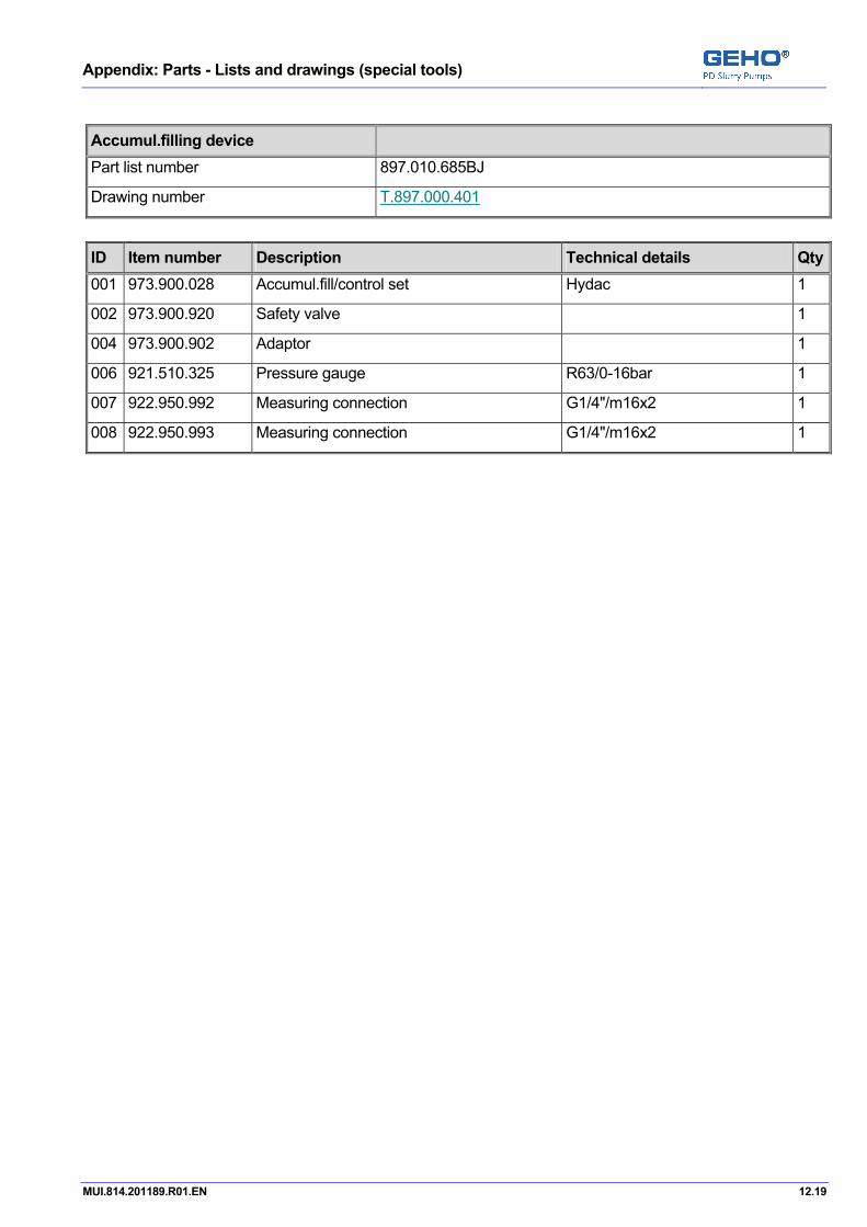
Appendix: Parts - Lists and drawings (special tools)
MUI.814.201189.R01.EN 12.19
Accumul.filling device Part list number 897.010.685BJ
Drawing number T.897.000.401
ID Item number Description Technical details Qty001 973.900.028 Accumul.fill/control set Hydac 1
002 973.900.920 Safety valve 1
004 973.900.902 Adaptor 1
006 921.510.325 Pressure gauge R63/0-16bar 1
007 922.950.992 Measuring connection G1/4"/m16x2 1
008 922.950.993 Measuring connection G1/4"/m16x2 1

Appendix: Parts - Lists and drawings (special tools)
12.20 MUI.814.201189.R01.EN
Pos: 69 /--- Section break - Odd page --- @ 0\mod_1136277036628_0.doc @ 765

Appendix: Electrical information
MUI.814.201189.R01.EN 13.1
Pos: 70 /GEHO/Heading/H1/#. Appendix: Electrical information @ 1\mod_1169571364915_31.doc @ 11974
13 Appendix: Electrical information Pos: 71 /GEHO/General/Attention, Warning and Note/DANGER - Safety - Obey safety instructions and procedures @ 0\mod_1136886637385_31.doc @ 1007
DANGER
• Obey the safety instructions. • Obey the working procedures.
Pos: 72 /GEHO/Electrical information/Project/201189 @ 5\mod_1226310593327_31.doc @ 40311
Description Drawing number Logic diagram S.814.201189.05
Control box and terminal box S.814.201189.06
Electrical installation S.814.201189.07
Motor control circuit S.814.201189.09
Appendix: Electrical information
13.2 MUI.814.201189.R01.EN
Pos: 73 /--- Section break - Odd page --- @ 0\mod_1136277036628_0.doc @ 765
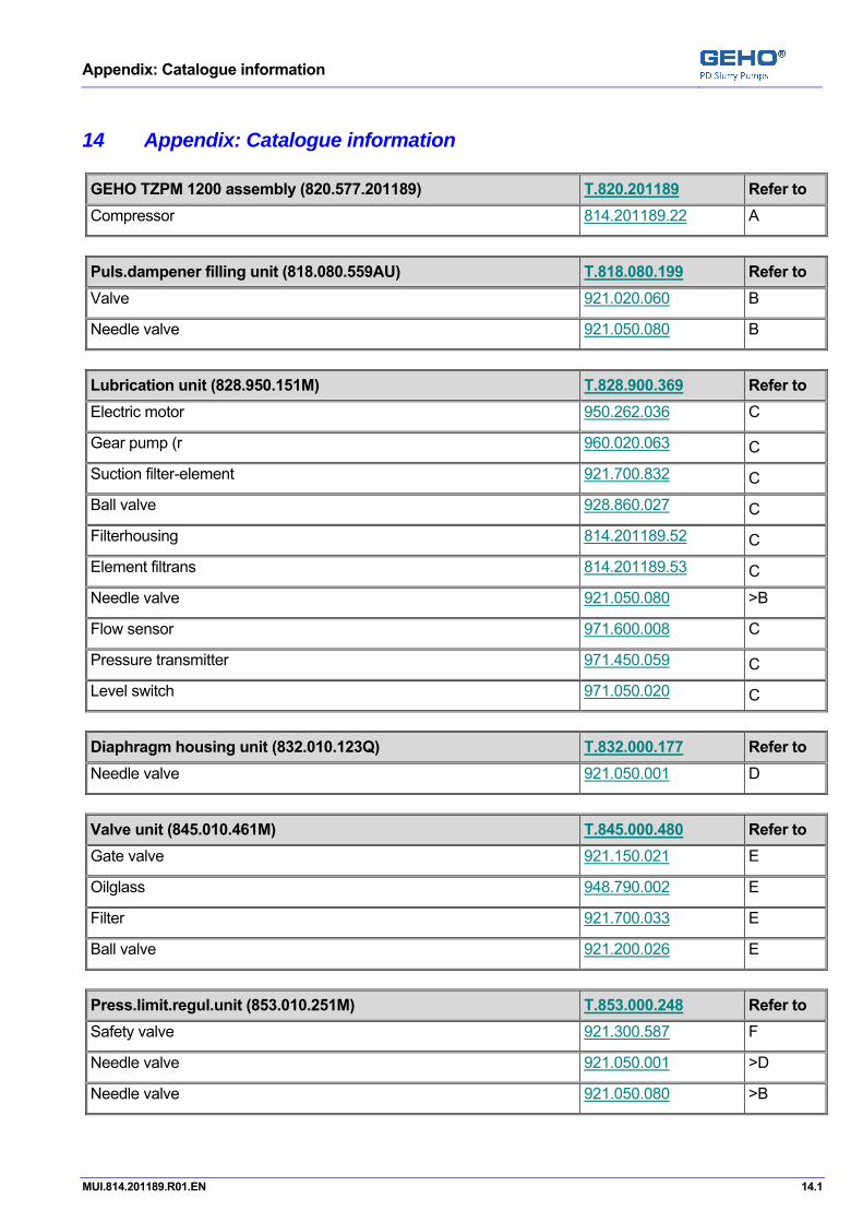
Appendix: Catalogue information
MUI.814.201189.R01.EN 14.1
Pos: 74 /GEHO/Heading/H1/#. Appendix: Catalogue information @ 1\mod_1169571471475_31.doc @ 11978
14 Appendix: Catalogue information Pos: 75 /GEHO/Catalogue information/Project/201189 @ 5\mod_1226310897348_0.doc @ 40318
GEHO TZPM 1200 assembly (820.577.201189) T.820.201189 Refer to Compressor 814.201189.22 A
Puls.dampener filling unit (818.080.559AU) T.818.080.199 Refer to Valve 921.020.060 B
Needle valve 921.050.080 B
Lubrication unit (828.950.151M) T.828.900.369 Refer to Electric motor 950.262.036 C
Gear pump (r 960.020.063 C
Suction filter-element 921.700.832 C
Ball valve 928.860.027 C
Filterhousing 814.201189.52 C
Element filtrans 814.201189.53 C
Needle valve 921.050.080 >B
Flow sensor 971.600.008 C
Pressure transmitter 971.450.059 C
Level switch 971.050.020 C
Diaphragm housing unit (832.010.123Q) T.832.000.177 Refer to Needle valve 921.050.001 D
Valve unit (845.010.461M) T.845.000.480 Refer to Gate valve 921.150.021 E
Oilglass 948.790.002 E
Filter 921.700.033 E
Ball valve 921.200.026 E
Press.limit.regul.unit (853.010.251M) T.853.000.248 Refer to Safety valve 921.300.587 F
Needle valve 921.050.001 >D
Needle valve 921.050.080 >B
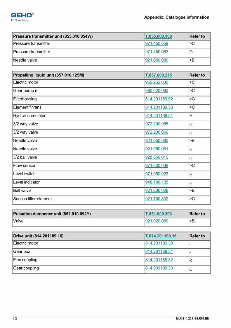
Appendix: Catalogue information
14.2 MUI.814.201189.R01.EN
Pressure transmitter unit (855.010.054W) T.855.000.100 Refer to Pressure transmitter 971.450.059 >C
Pressure transmitter 971.450.063 G
Needle valve 921.050.080 >B
Propelling liquid unit (857.010.125M) T.857.000.215 Refer to Electric motor 950.262.036 >C
Gear pump (r 960.020.063 >C
Filterhousing 814.201189.52 >C
Element filtrans 814.201189.53 >C
Hydr.accumulator 814.201189.51 H
3/2 way valve 972.200.065 H
3/2 way valve 972.200.066 H
Needle valve 921.050.080 >B
Needle valve 921.050.081 H
3/2 ball valve 928.860.019 H
Flow sensor 971.600.008 >C
Level switch 971.050.023 H
Level indicator 948.790.105 H
Ball valve 921.200.026 >E
Suction filter-element 921.700.832 >C
Pulsation dampener unit (851.010.092Y) T.851.000.393 Refer to Valve 921.020.060 >B
Drive unit (814.201189.16) T.814.201189.16 Refer to Electric motor 814.201189.30 I
Gear box 814.201189.31 J
Flex.coupling 814.201189.32 K
Gear coupling 814.201189.33 L

Appendix: Catalogue information
MUI.814.201189.R01.EN 14.3
Hydr.pump-unit (897.010.710) T.897.000.318 Refer to Hydraulic pump 960.010.036 M
Accumul.filling device (897.010.685BJ) T.897.000.401 Refer to Accumul.fill/control set 973.900.028 N
Safety valve 973.900.920 O
Electrical unit (858.010.117M) T.814.201189.43 Refer to PLC PLC.201189 P
===== Ende der Stückliste =====

Appendix: Catalogue information
14.4 MUI.814.201189.R01.EN
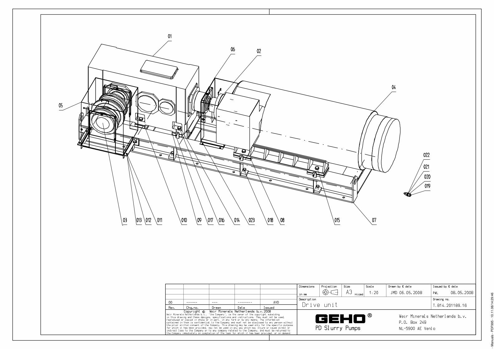
- M
anua
ls -
PD
F995
- 10
.11.
08/1
4:29
:46

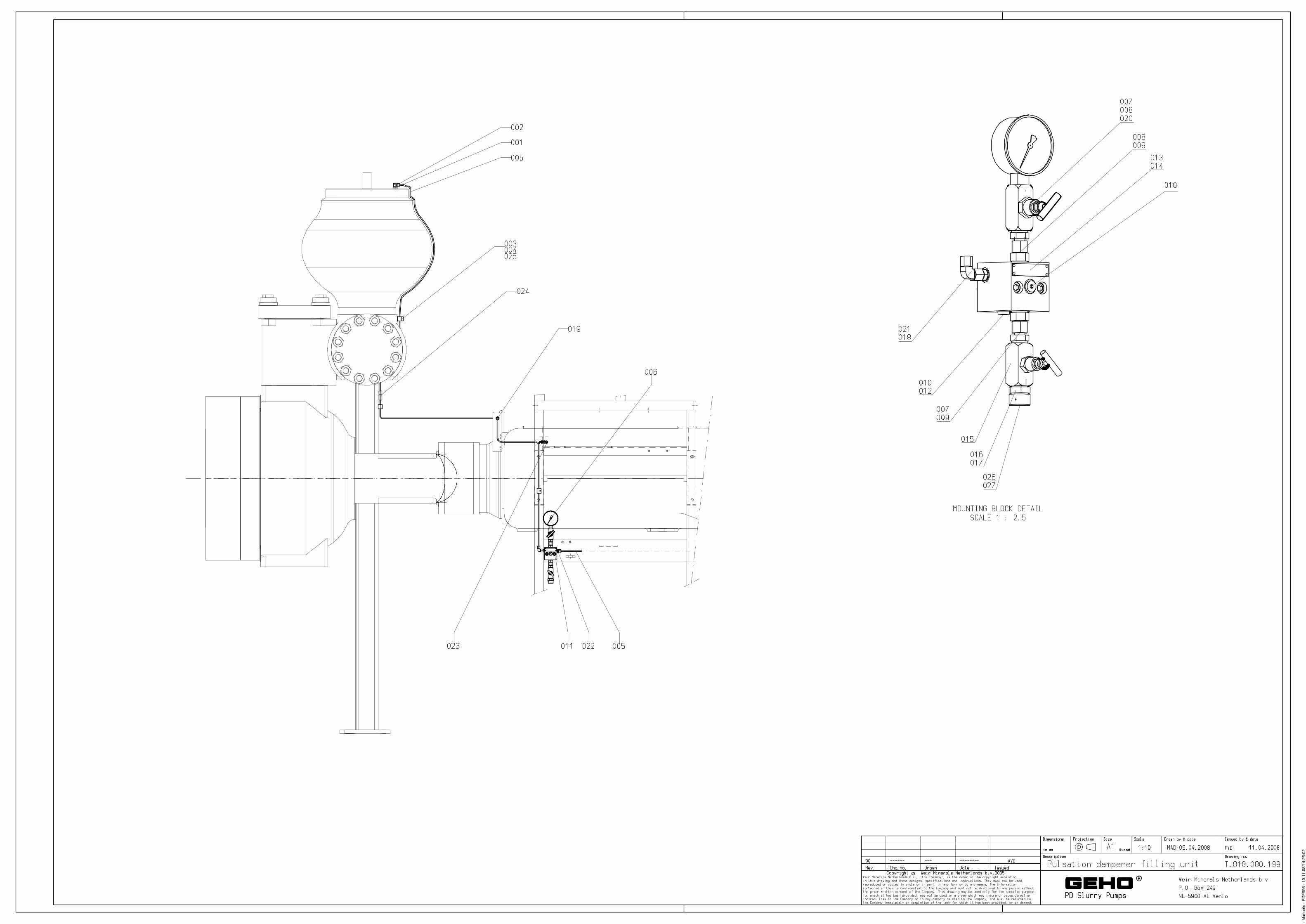
- M
anua
ls -
PD
F995
- 10
.11.
08/1
4:26
:02
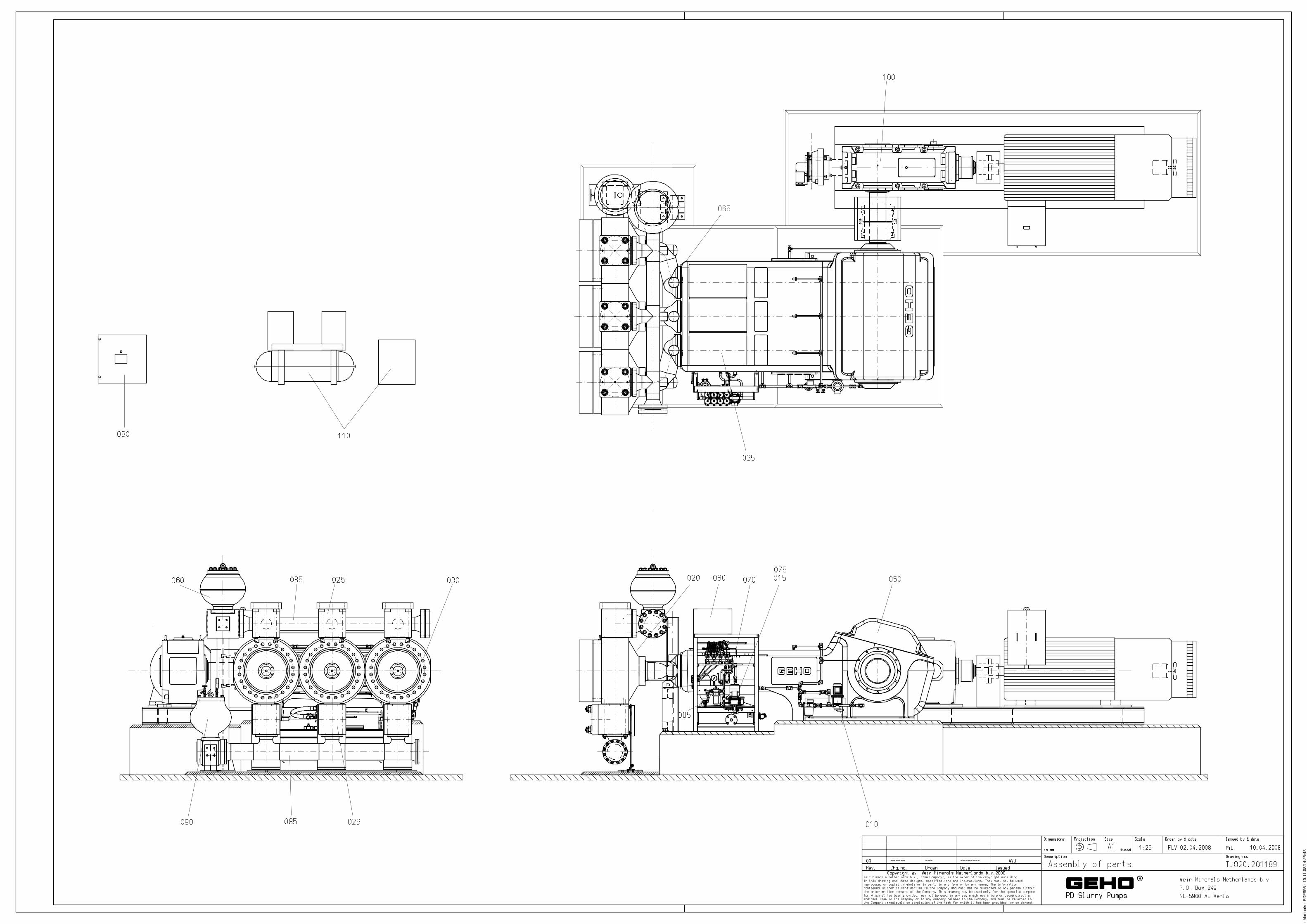
- M
anua
ls -
PD
F995
- 10
.11.
08/1
4:25
:48

- Manuals - PDF995 - 10.11.08/14:26:16
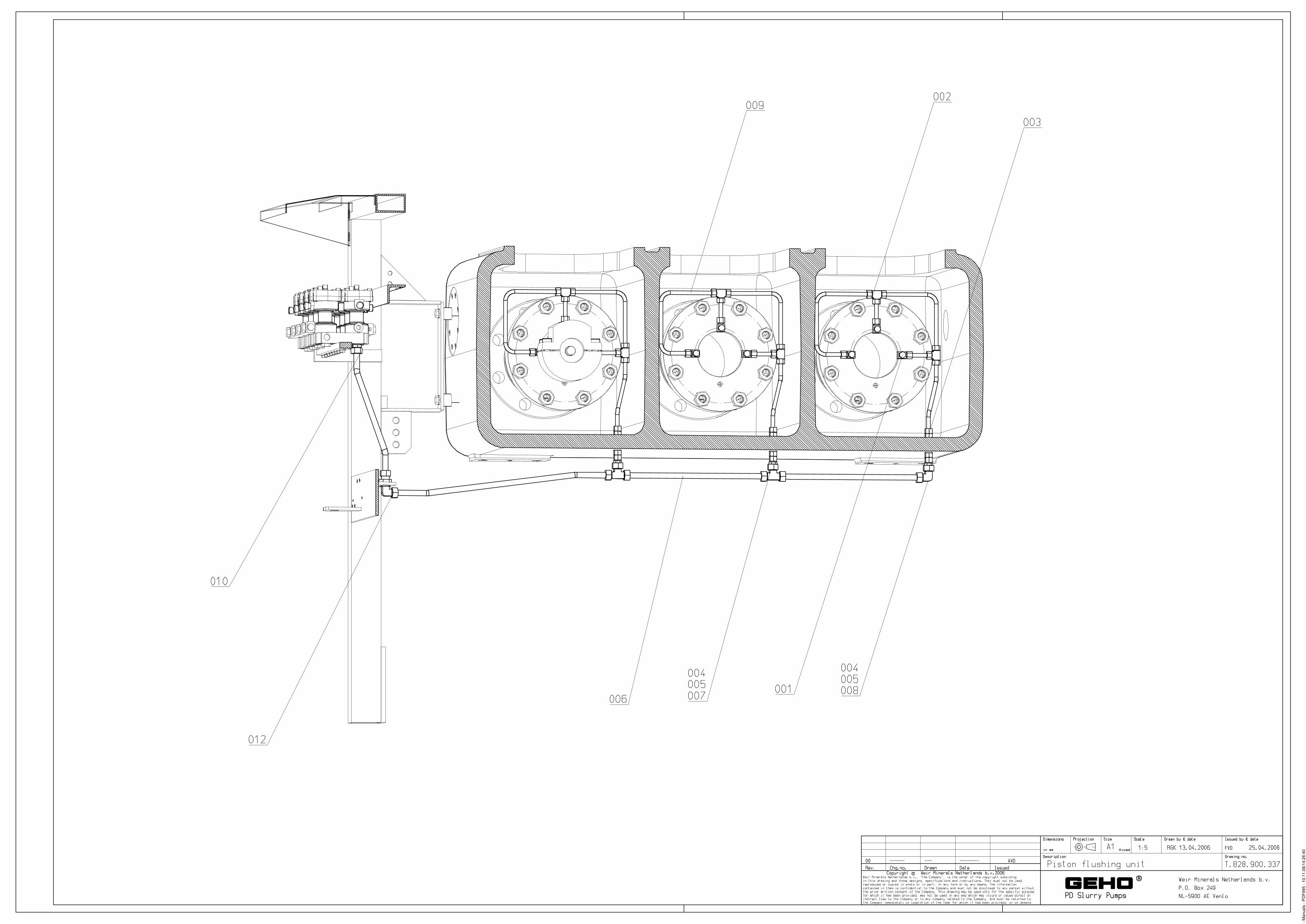
- M
anua
ls -
PD
F995
- 10
.11.
08/1
4:26
:40
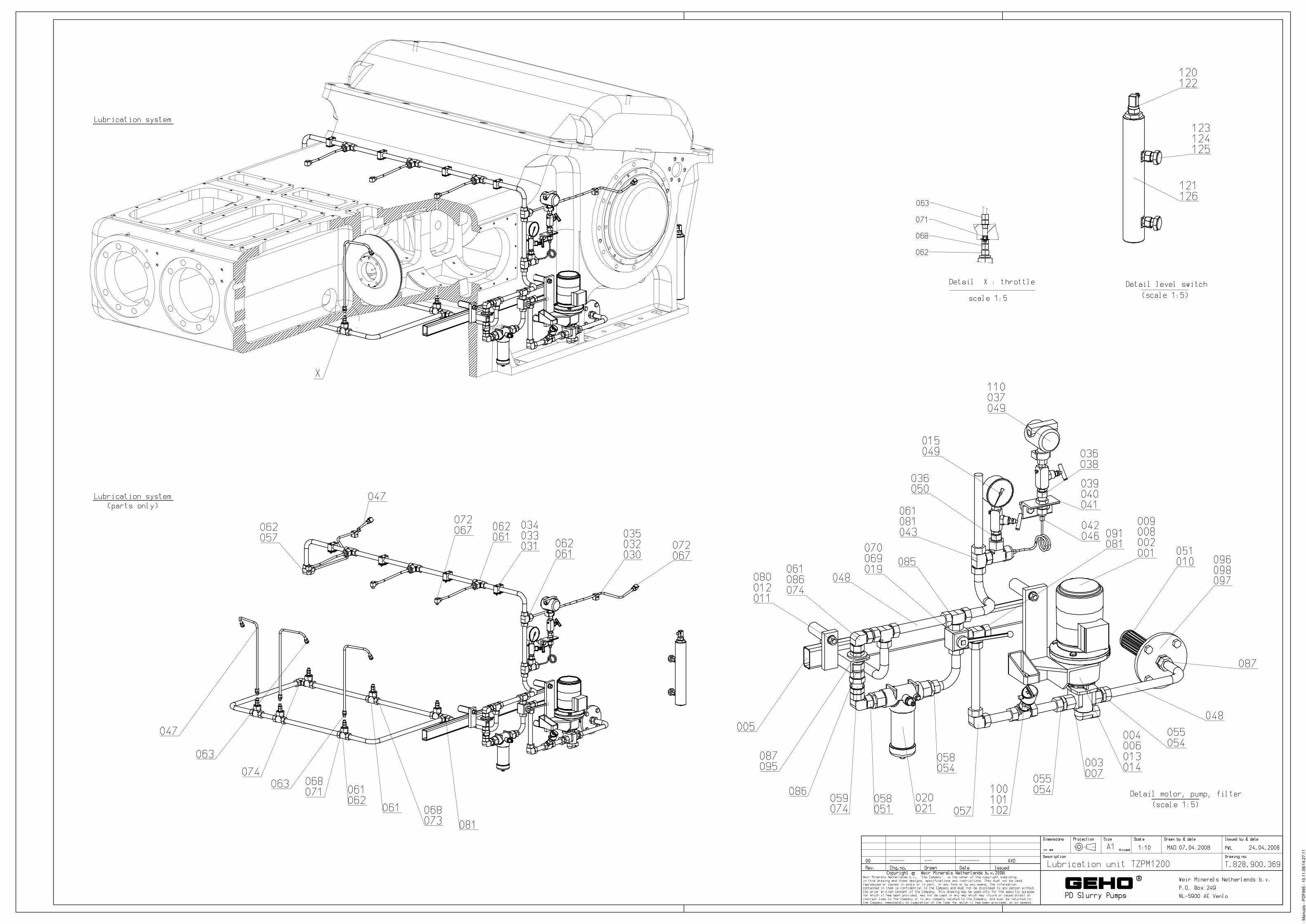
- M
anua
ls -
PD
F995
- 10
.11.
08/1
4:27
:11
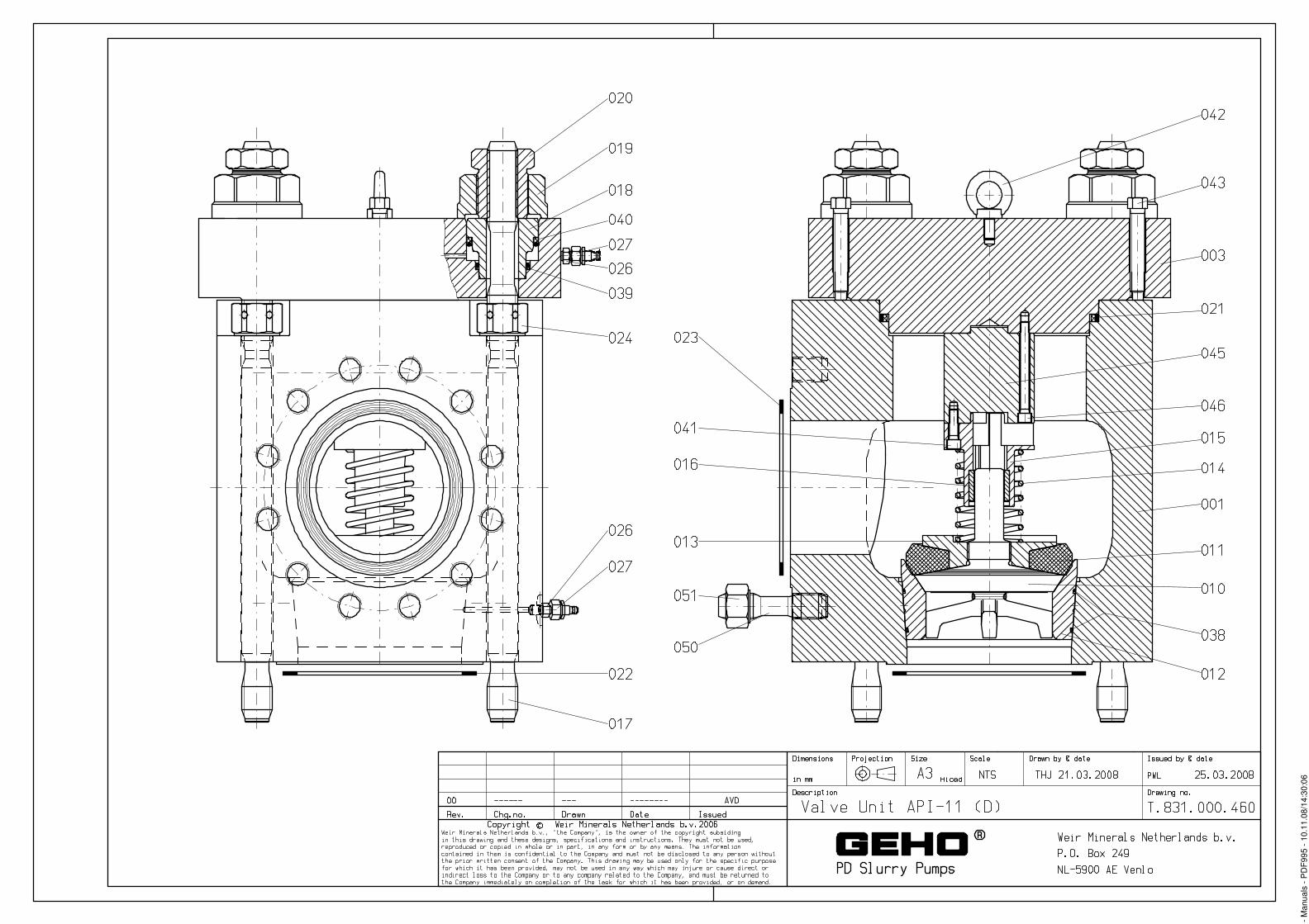
- M
anua
ls -
PD
F995
- 10
.11.
08/1
4:30
:06
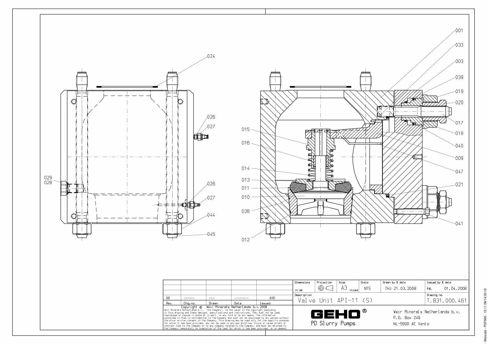
- M
anua
ls -
PD
F995
- 10
.11.
08/1
4:30
:16

- M
anua
ls -
PD
F995
- 10
.11.
08/1
4:30
:28

- M
anua
ls -
PD
F995
- 10
.11.
08/1
4:30
:54


- M
anua
ls -
PD
F995
- 10
.11.
08/1
4:31
:25

- M
anua
ls -
PD
F995
- 10
.11.
08/1
4:31
:37

- M
anua
ls -
PD
F995
- 10
.11.
08/1
4:27
:45

- M
anua
ls -
PD
F995
- 18
.11.
08/1
1:05
:35

- Manuals - PDF995 - 10.11.08/14:31:49

- M
anua
ls -
PD
F995
- 18
.11.
08/1
1:05
:41
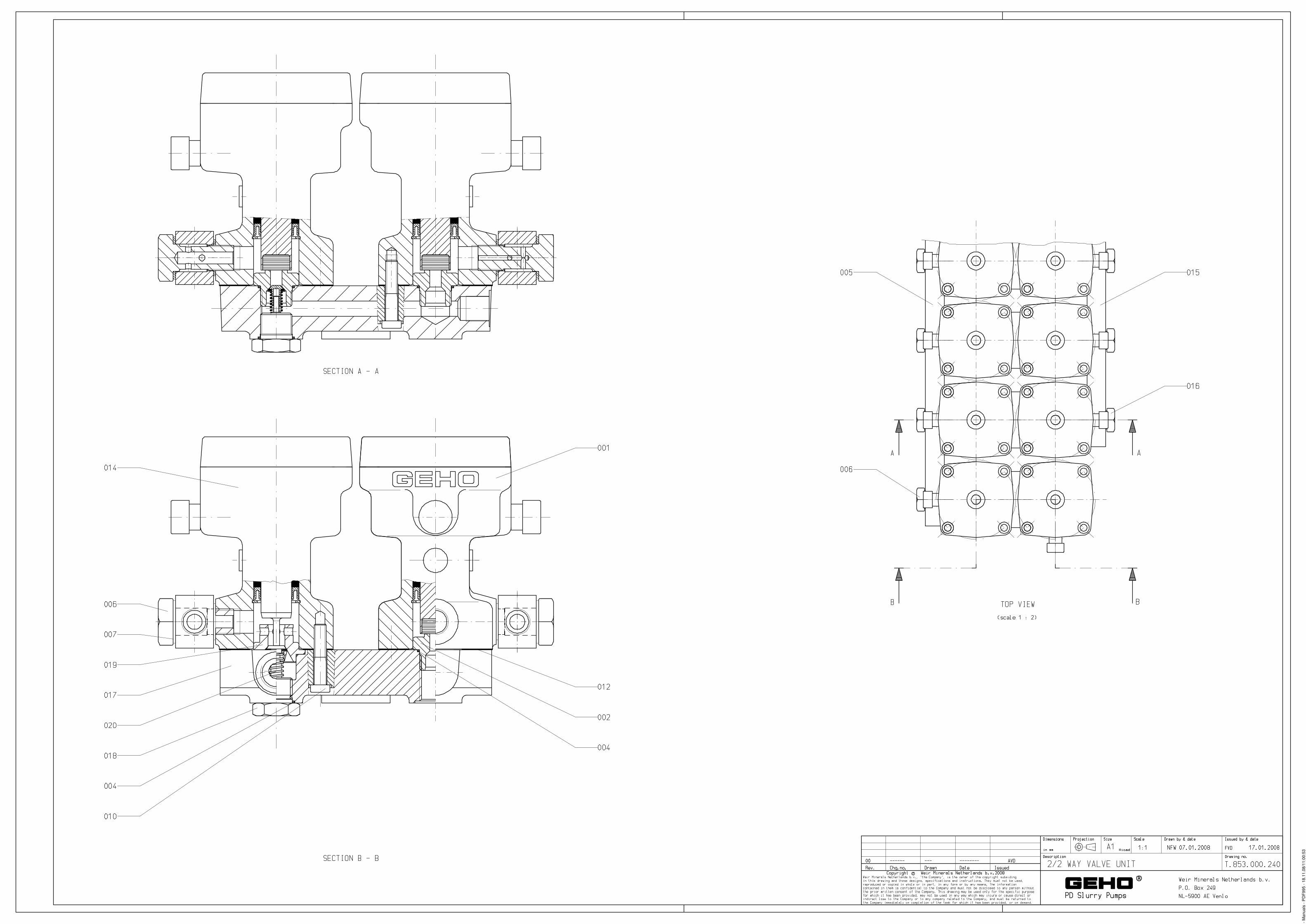
- M
anua
ls -
PD
F995
- 18
.11.
08/1
1:00
:53

- M
anua
ls -
PD
F995
- 10
.11.
08/1
4:32
:34

- M
anua
ls -
PD
F995
- 10
.11.
08/1
4:32
:41

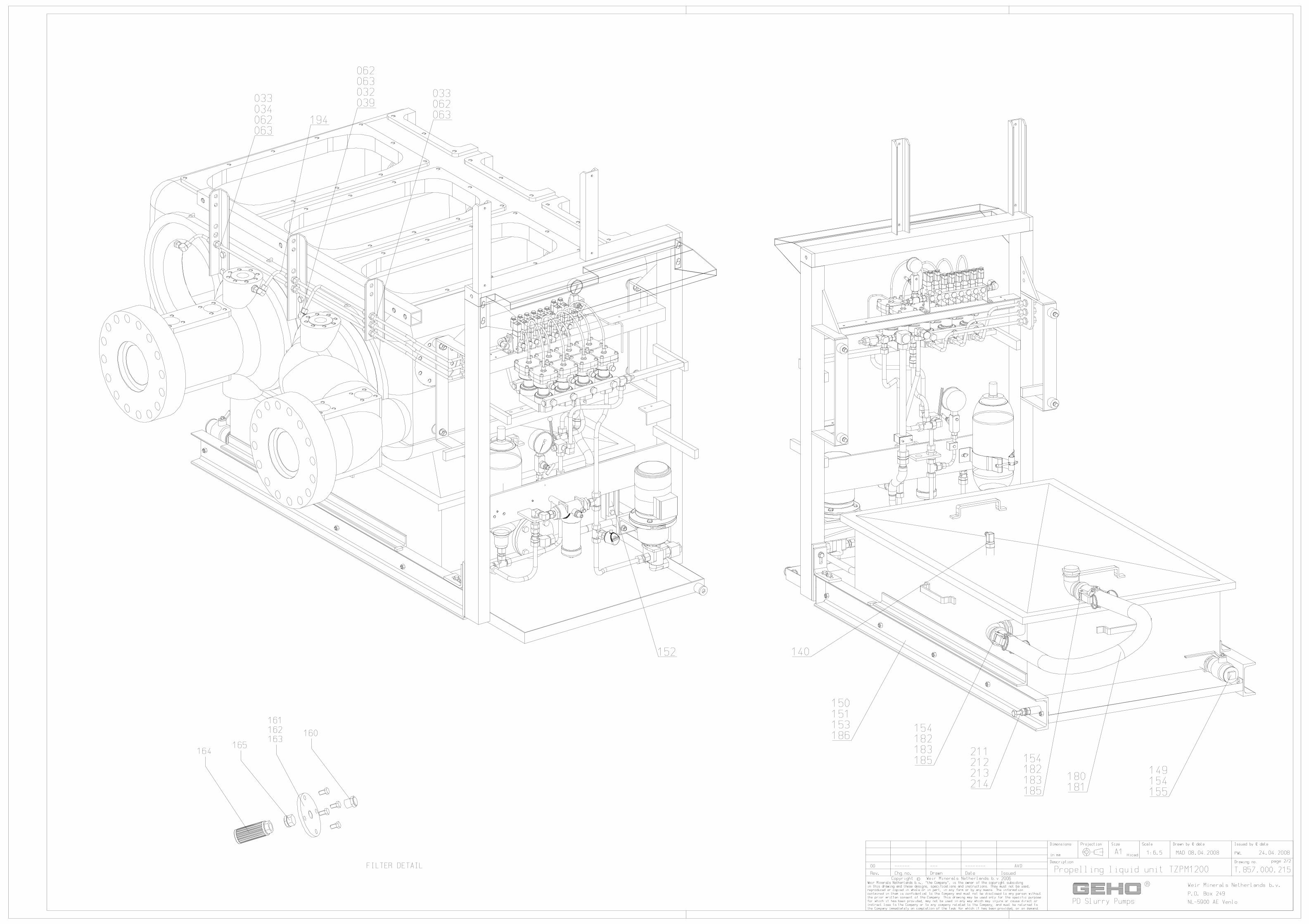

- M
anua
ls -
PD
F995
- 10
.11.
08/1
4:32
:58

- M
anua
ls -
PD
F995
- 18
.11.
08/1
1:06
:32

- M
anua
ls -
PD
F995
- 18
.11.
08/1
1:06
:35

- M
anua
ls -
PD
F995
- 10
.11.
08/1
4:33
:28

- M
anua
ls -
PD
F995
- 10
.11.
08/1
4:33
:30
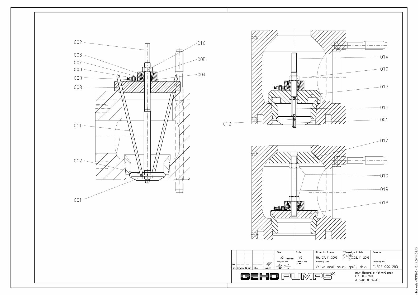
- M
anua
ls -
PD
F995
- 10
.11.
08/1
4:33
:43

- M
anua
ls -
PD
F995
- 18
.11.
08/1
1:06
:41

- M
anua
ls -
PD
F995
- 18
.11.
08/1
1:07
:29

- M
anua
ls -
PD
F995
- 18
.11.
08/1
1:07
:44
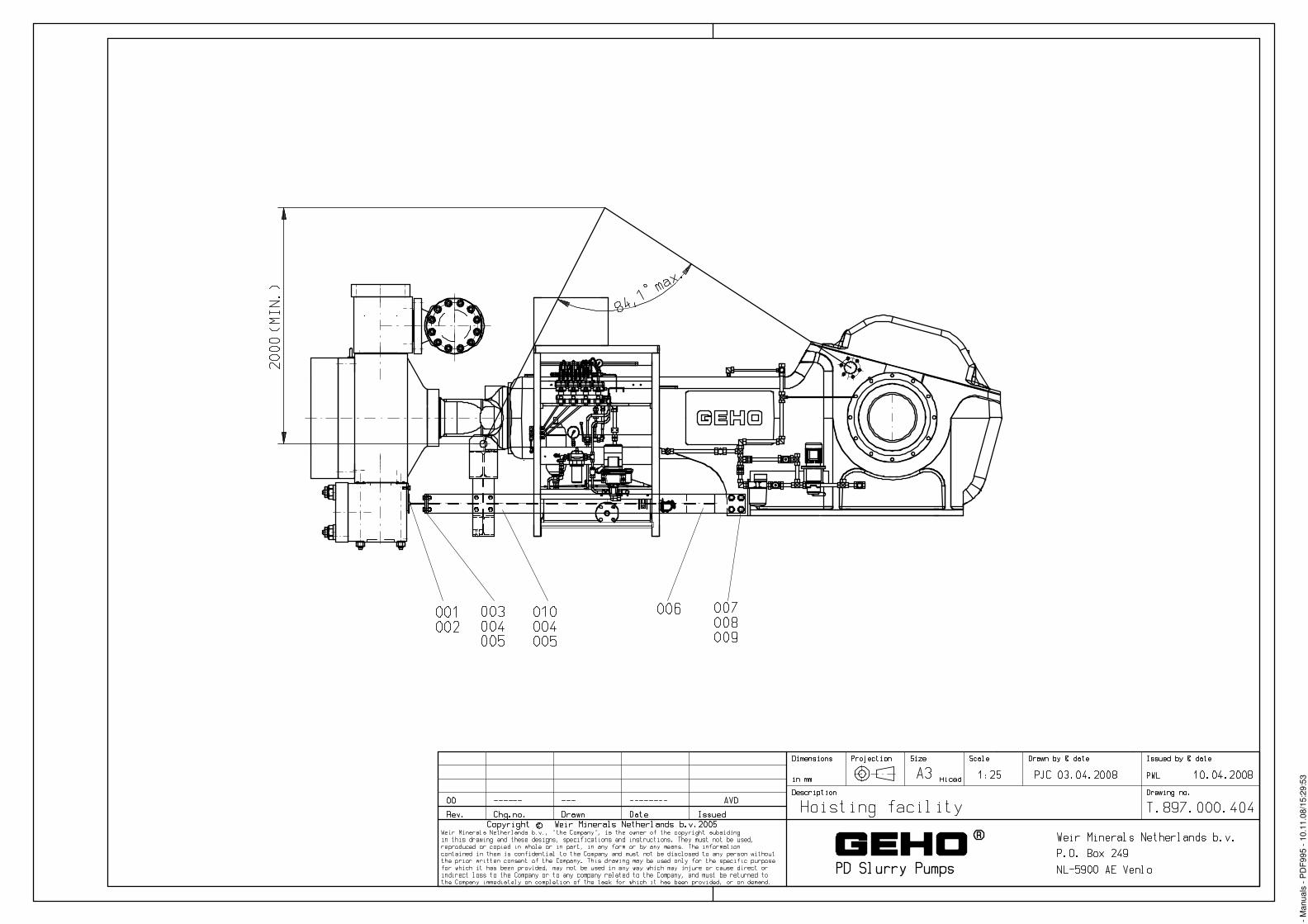
- M
anua
ls -
PD
F995
- 10
.11.
08/1
5:29
:53