Manual Gearbox Design - Alec Stokes Gearbox Design … · vi Contents Bevel gears Crossed helical...
172
Transcript of Manual Gearbox Design - Alec Stokes Gearbox Design … · vi Contents Bevel gears Crossed helical...


Contents
Preface Acknowledgements Introduction
1 Crown wheel and pinion Torque at rear axles Vehicle performance torque Axle torque (from maximum engine torque through the lowest
Axle torque - from wheel slip Drive pinion torque Stress determination and scoring resistance
Bending stress Contact stress
gear ratios)
2 Internal running gear Shaft stressing for size Input shaft Intermediate shaft Output shaft Internal gears Lubrication system Gear engagement Interlock system Reverse gear Differential Bearing arrangement and casing
3 Lubrication of gears Principles of gear lubrication
Group A Spur gears Helical gears
vii
ix
... V l l l
1 4 5
16 16 19 19 19 20 22 22 26 27 27 30
33 36 36 36 37

vi Contents
Bevel gears Crossed helical gears
Worm gears Hypoid gears
Tests for lubricating oils
Group B
4 Gear tooth failures Gear tooth failure
Tooth fracture Tooth surface failures
5 Crowa wheel and pinion designs Klingelnberg palloid spiral bevel gear calculations
Basic conception Terminology Bevel gear calculations ‘0’-bevel gears Bevel gear V drives Tooth profiles Gear blank dimensions Formulae for the determination of the external forces Strength of teeth Rules for the examination of the tooth profile by the
graphic method Example of spiral bevel gear design
6 Oerlikon cycloid spiral bevel gear calculations Design features Production features Gear calculation with standard En cutters Strength calculation
7 Gearbox design - rear-engined racing cars Basic aims
In-line shaft arrangement Internal gear arrangement Face-dog selectors Bearhg arrangement Crown wheel and pinion layout Differential location and type Transverse-shaft arrangement Selector system Selector interlock system Lubrication method Gearbox casing
Materials guide
38 38 39 39 40 46
50 52 53 54
61 66 66 67 67 80 82 83 84 88 96
100 106
113 113 113 117 1 30
134 134 135 137 137 139 141 143 148 150 152 155 157 158
Index 161

Preface
This book has been written in an effort to put down on paper some of the experience I have gained during my forty-five years in the transmission design field, thirty-one years of which was designing Formula One gearboxes, and the last five years before retirement with Lotus Engineering as Chief Designer - Transmissions. Knowing of no other book that covered this subject made me more determined to proceed with it.
I have attempted to work through the design procedure in the same order used on the many gearbox designs I have been involved with. Alternative types of crown wheel and pinion designs to the widely used Gleason system are covered, that is, Klingelnberg and Oerlikon. Various types of differential are described along with interlock systems which prevent the selection of more than one gear at a time. It contains a wide coverage of gear failures, their causes and requirements to prevent further failures, together with an engineering understanding of lubrication and its application. The book also includes a list of materials along with the heat treatment applied and race-proven in the B.R.M. Formula One Racing Transmissions as a guide to the designer.
A . Stokes
vii


Introduction
The purpose of this book is to provide both the student and young professional design engineer with an overall guide to the amount of work involved in the design of a manually operated automotive gearbox, and the problems that can be encoun- tered both during the design stages and in operation.
I am unaware of any other book which gives such information and at the same time attempts to provide a methodical system of solving what appears to be a fairly straightforward engineering design problem to the majority of people, but often turns into one requiring great care and dedication. Otherwise the design can develop into a very complex piece of machinery which is both difficult and expensive to produce and proves incapable of achieving the original objectives that were laid down for the transmission.
The purpose of any gearbox or transmission is to provide a drive, which often includes a range of selected intermediate gear ratios, between the power unit and the final source of the drive, whether it is to be used in an industrial, marine or automotive application.
In the automotive industry this means the provision of a drive between the engine and the road wheels. This drive must be smooth, quiet and efficient and capable of being produced to a strict budget price while proving extremely reliable. With the exception of a transversely mounted engine and gearbox unit, the drive will at some point have to change direction through a 90" angle.
Starting with the 90" angle drive, this being one of the following types of gear:
(a) a pair of straight bevel gears (b) a pair of spiral bevel gears (c) a pair of hypoid bevel gears and commonly known as the crown wheel and
this book will attempt to follow the design sequence used by the author during the design of a manually operated automotive gearbox. Each of the chapters will deal with a-specific problem which is encountered during the design phases and during operation.
pinion
Chapter 1 . This chapter begins with a comparison of the merits of spiral bevel gears and hypoid gears when employed as the final drive in the automotive gearbox,
i x

x Introduction
i.e. the crown wheel and pinion. Then the identification of the hand of spiral of both the spiral and hypoid bevel gears is explained, followed by the recommended hand of spiral. The major portion of the remainder of the chapter gives the details of the ‘Empirical formulae and calculation procedures’ produced by the American Gleason Gear Co. for rear axle or final drive units. These formulae give the following details: (a) torque at rear axles, and vehicle performance torque (b) axle torque, and axle torque from wheel slip (c) drive pinion torque (d) stress determination and scoring resistance
The final pages cover the calculation of the crown wheel and pinion ratio and the layout of the initial lines for the gearbox design.
These foregoing calculations provide a means of ensuring that the crown wheel and pinion operates satisfactorily relative to its specific environment and is designed with adequate strength to cope with the range of torques involved.
Chapter 2. This chapter attempts to describe the process of designing the internal running gear, starting with the range o f internal ratios, the input shaft, the intermediate shaft and the output shaft. The formulae for stressing these shafts are given, to enable the size of the shafts to be finalized. This is followed by the calculation of the road speed in the various internal ratios, and the selection of the ratios most suited for the particular application. The next pages describe various types of gear engagement systems and the need for an interlock system which prevents more than one internal gear being selected at any given time.
The final pages cover the various types of differential that can be used, the choice of bearings and oil seals and finally the type of lubrication system required to suit the application. The closing pages also describe the layout of the gearbox internal running gear and the gearbox casing; the situations that the casing must be able to cope with are also described in some detail.
Chapter 3. This chapter is totally dedicated to a complete description of the lubrication of gears. Starting with a brief history of the many dramatic changes that have been made in the lubrication of gears and lubrication in general engineering in the past few years, the various methods used to apply lubricant to gears are listed and explained. The problems of applying lubricant to the various types of gear, with the varying characteristics in the way in which the teeth of the mating gears move relative to each other, are also covered in some detail. This is followed by some advice on the type of lubrication to be chosen from the varying applications relative to the type of gear form and the pitch line speed. Then the loss in efficiency due to excess or inadequate lubrication is analysed. The final pages look at different types of lubricant used in gear drives.
Chapter 4 . This chapter is dedicated to all the various forms of gear failure that can be encountered by the engineer where gear trains are concerned. In the examination of the failures, the varying reasons or causes of failure, along with suggested remedies, are listed.
(a) complete fracture of the gear tooth, usually occurring at the root of the tooth
The failures in any gear train fall into one of two forms, as follows:
which breaks away in one whole section
Introduction xi
(b) damage or destruction of the working or mating faces of the gear teeth
The factors which either individually or as a combination result in the above failures are listed, before the identification of the failures and their respective remedies.
Chapter 5 . The different forms of crown wheel and pinion that are available to the designer are discussed in this chapter. The three forms are:
(a) the Gleason system, produced by the Gleason Gear Co. of America (b) the Oerlikon system, from the Oerlikon Co. of Switzerland (c) the Klingelnberg system, introduced by the German company, Klingelnberg
The differences between the three methods are discussed, together with a general description of the forces created when a pair of spiral bevel gears run together. The movement of the tooth contact pattern as the load applied to the gear increases is also discussed. The final pages of the chapter give a brief description of, and the calculations for, the manufacturing and inspection dimensions for a pair of Klingelnberg palloid spiral bevel gears.
Chapter 6. The design features, the production features and the calculation of the manufacturing and inspection dimensions for a pair of Oerlikon cycloid spiral bevel gears are given in the early part of this chapter. The latter part advises the designer of the varying stages which are usually covered by the design, production and development departments prior to the introduction of a new transmission onto the market, and emphasizes the co-operation necessary between these departments if the product is to be successful.
Chapter 7. This final chapter covers the design of a racing-type rear engine mounted gearbox. The opening pages deal with the aims of the gearbox and the reasons for each of the aims. Following this, the design procedures for the internal gear pack are discussed, along with the arrangements of the various shafts. This covers the location of the shafts, together with their supporting bearings. Different layouts and bearing location methods for the crown wheel and differential are covered, as are the methods used to locate these assemblies and some of the problems that can be encountered with them. This is followed by a listing and brief description of the varying types of differential units that are used in racing gearboxes.
Having discussed the ‘in-line’ layout for the internal gear pack, the next few pages describe a transverse gearbox layout where the internal gear pack lies across the car chassis. The problems of internal ratio changing with the transverse gearbox layout are discussed, along with the major problem which can affect the overall car performance, namely a simple and positive gear change system that can be fitted and adjusted so that the driver is able to make quick and totally reliable gear change movements.
Following the section giving details of these problems, the advantages of using a transverse gearbox are listed, together with the practical reasons for these advantages. This is followed by a description of the gear change systems tha t have been utilized in the past, along with the arrangements of the selector forks that give the quickest gear change movements. An interlock system that prevents the selection of more than one gear at a time is an essential part o f the gear cl~anpc

xii Introduction
system. As well as covering the positive location of the selector dog rings, various systems that have been used are listed.
The later part of this chapter, having arrived at a preliminary design and layout for the gearbox internals, deals with the problems that can be encountered with the lubrication system and various methods that are used to cope with the high speeds and heavy tooth loads involved. The design of the gearbox casings and the detailing of each component part ready for manufacture are given in the final pages, along with a guiding list of materials that the author used for the various components during his thirty or so years’ involvement in the design of Formula One racing gearboxes.

Crown wheel and pinion
In all manual automotive gearboxes, except those designed specifically for motor racing or other uses where noise is not a problem, the crown wheel and pinion usually consists of either a pair of spiral or hypoid gears. Both the spiral and hypoid bevel gears have certain advantages over each other, all of which must be seriously taken into account when a new design of gearbox or transmission is being initiated.
Comparison of the two types of bevel gears and their advantages can be listed as follows :
1. Noise. The ability to lap the entire tooth surface of a hypoid gear, as there is lengthwise sliding motion between the mating teeth at every point, generally results in smoother and consequently quieter running gears. 2 Strength. Due to the offset required in a pair of hypoid bevel gears, the crown wheel and the pinion have different spiral angles, which results in the two gears having the same normal pitches. It is usual to design the pinion with a coarser transverse pitch than the crown wheel; this results in a larger pinion diameter than for the corresponding spiral bevel pinion. The amount of the enlargement is dependent upon the amount of the pinion offset, and results in the following advantages:
(a) a better bending fatigue life than that of the corresponding spiral bevel gears (b) the use of a larger shaft or shank diameter on the hypoid pinion
But it must be realized that with low gear ratios, the use of hypoid gears may result in very large'diameter pinions and therefore it may prove advantageous to use a spiral bevel design in such situations. These factors must be fully and carefully investigated at the initial design stages. 3 EfJiciency. The efficiency of both hypoid and spiral bevel gears can be very high, although the efficiency of hypoid gears is slightly less than that of the equivalent spiral bevel gears, due to the increase in the sliding motion between the mating teeth. Efficiencies as high as 99% have been obtained with spiral bevel gears, as against the 96% obtained with hypoid bevel gears when tested on the same rig in laboratory conditions. This efficiency is dependent upon the following:
(a) the amount of the hypoid offset
2 Manual Gearbox Design
(b) the load transmitted - it is important to note that, during these tests, the higher the loads transmitted the higher the efficiencies of the gear pair became
4 Sliding. Both spiral and hypoid bevel gears have sliding motion in the profile direction, but only the hypoid bevel gear has lengthwise sliding motion. This increase in sliding motion results in a rise in heat generated, with the resultant loss in efficiency. The increase in heat generated means careful investigation into the problems created in the gear lubrication and cooling system in an attempt to reduce to and maintain reasonable operating temperatures. 5 Scoring resistance. One result of the spiral bevel gear having no lengthwise sliding motion is that it is generally less susceptible to scoring than the hypoid gear. However, the problem of scoring in hypoid bevel gears can usually be solved with the co-operation of the lubrication and tribology engineers. 6 Pitting resistance. Due to the increased size of the hypoid pinion and its larger spiral angle, the relative radius of curvature between the mating teeth on a hypoid bevel gear pair is greater than that of a corresponding spiral bevel gear pair, resulting in lower contact stresses between the hypoid tooth surfaces with a similar reduction in the possibility of pitting. In actual practice, loads up to 1.5 times greater have been carried by hypoid bevel gears than the loads carried by an equivalent pair of spiral bevel gears, but this extra load-carrying capacity can be closely linked to the amount of hypoid offset, which must be carefully checked in the stress calculations during the early stages of design. 7 Lubrication. The subject of gear lubrication is more fully covered in Chapter 3, but the following points refer especially to spiral and hypoid bevel gears:
(a) both spiral and hypoid bevel gears have combined rolling and sliding motion between the teeth, the rolling action being beneficial in maintaining a film of oil between the tooth mating surfaces
(b) due to the increased sliding velocity between the hypoid gear pair, a more complicated lubrication system may be necessary, as is more fully explained in Chapter 3
8 Mounting and assembly. Both spiral and hypoid bevel gears have the same sensitivity to malalignment in mountings on assembly and under load while in operation. This problem can be controlled by the lengthwise curvature of the teeth, i.e. the diameter of the cutter, and the tooth contact development. Rigid bearing mountings will obviously reduce the adverse effects of the gear sensitivity. The assembly of a hypoid bevel gear pair can be slightly more complicated than that of an equivalent spiral bevel gear pair, mainly due to the inclusion of the hypoid offset, which can create problems in measuring the mounting distance during assembly, thus requiring special gauging equipment. 9 Bearing sizes. Using a pair of spiral bevel or hypoid bevel gears of the same average spiral angle will result in the hypoid gearwheel having a lower spiral angle than the equivalent spiral gearwheel, and the hypoid pinion having a higher spiral angle than the equivalent spiral pinion. As a result of the above, the axial thrust on the hypoid pinion bearings will be greater, while the axial thrust on the hypoid gearwheel bearings will be less, than the axial thrust on the bearings of an equivalent spiral bevel gear pair. The facility to use a larger shank or shaft diameter with a

Crown wheel and pinion 3
hypoid pinion obviously assists with the problem of the higher thrust load on the hypoid pinion, by permitting the use of larger bearings than those which can be used on the equivalent spiral bevel pinion. 10 Casing sizes. The larger hypoid pinion diameter and its need for higher load-carrying capacity bearings can result in the casing for a pair of hypoid gears being larger than that for an equivalent pair of spiral bevel gears. This also applies to the sue of the differential casing, which carries the hypoid gearwheel. As the offset of a pair of hypoid gears is increased, so the pinion face is displaced axially towards the centre-line of the hypoid gearwheel, thus reducing the diametral space available for the differential. For low gear ratios, the outside diameter of the hypoid pinion may become excessive and consequently reduce the clearance between the gearbox casing and the ground. This applies especially when ratios are 2: 1 or less. The following rules can be used as a general guide:
(a) Ratios 4.5:Z and above. The hypoid pinion, being larger, permits the use of larger pinion shaft diameters which can be advantageous.
(b) Ratios between 2:Z and 4.5:Z. Either spiral or hypoid bevel gears will be satisfactory, but it should be noted that as the ratio decreases so the diameter of the hypoid pinion increases relative to the size of the corresponding spiral bevel pinion.
1 1 Manufacture. As both spiral and hypoid bevel gears are produced on the same machines, the manufacturing costs will be similar for either pair of gears, but the hypoid gears have two distinct advantages over spiral bevel gears from the production point of view:
(a) due to the larger pinion diameter of the hypoid bevels, the cutter point may be larger than the one for the equivalent spiral bevel pinion, thereby reducing the number of cutter breakages
(b) with the lengthwise sliding motion between the mating teeth in a pair of hypoid gears, the teeth may be lapped more uniformly and in less time on the hypoid gears
12 Installation. The drive-line and the output drive are on the same horizontal plane when using spiral bevel gears, but with a pair of hypoid gears the output drive can be either above or elow the drive-line. This variation in output drive centre-line means that the hypoi, $ gear is more versatile, especially in the automotive transmission field. a’
Having made the decision which type of gear is most advantageous to the design, the hand of spiral to be used remains to be decided. In both spiral and hypoid bevel gears, the hand of spiral is denoted by the
direction in which the teeth curve. In a left-hand spiral, the teeth incline in a counter-clockwise direction away from the axis when looking at the face of a gearwheel or from the small end of the pinion, whereas in a right-hand spiral, the teeth incline away from the axis of the gear in a clockwise direction. The hand of spiral of any one member of the gear pair is always opposite to the hand of spiral of its mating gear in both hypoid and spiral bevel gears; therefore, when identifying the hand of a pair of either hypoid or spiral bevels it is usual to quote the hand of spiral of
4 Manual Gearbox Design
the pinion, i.e. a left-hand pair of hypoid or spiral bevel gears has a left-hand spiral pinion and a right-hand spiral gearwheel.
The hand of spiral dictates the direction of the thrust loads when the gears are loaded, and the hand of spiral should where possible be selected so that the thrust provides the motion for the pinion and gearwheel to move out of mesh when the gears are running under load in normal drive rotation, whenever this is permitted by the combination of the gear ratio, the pressure angle and the spiral angle.
Where this is not possible, the hand of spiral should be selected to give an outward direction thrust at the pinion.
From the notes on the previous pages of this chapter, it can be seen that the prime factor in the design of spiral or hypoid bevel gears must be the load capacity of the gears. The resistance to tooth breakage normally depends on the bending stress occurring in the root area of the tooth and resistance to surface failure from the contact stress occurring at the tooth surface.
Finally, the scoring resistance can be assessed by the critical temperature at the point of contact of the gear teeth.
To aid the checking of these stresses, the Gleason Gear Co. (Rochester, New York, USA) have produced the following ‘Empirical formulae and calculation procedures’ which closely reflect the design philosophy in a majority of current car designs.
Torque at rear axles
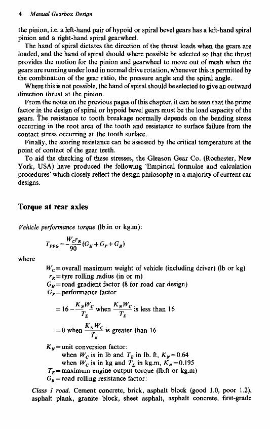
Vehicle performance torque (1b.in or kg.m):
where Wc=overall maximum weight of vehicle (including driver) (lb or kg) rR = tyre rolling radius (in or m)
GH=road gradient factor (8 for road car design) Gp = performance factor
is less than 16 when - K N wC = 16-- K N wC
TE =E
=O when - KNWC is greater than 16 TE
K, = unit conversion factor: when Wc is in lb and TE in lb. ft, K,=0.64 when W, is in kg and TE in kg.m, K,=0.195
TE=maximum engine output torque (1b.ft or kg.m) G , = road rolling resistance factor:
Class I road. Cement concrete, brick, asphalt block (good 1.0, poor 1.2), asphalt plank, granite block, sheet asphalt, asphalt concrete, first-grade

Crown wheel and pinion 5
bitumin macadam, wood block: in good condition 1.0 in poor condition 1.2 Class 2 road. Second-grade bitumin macadam, tar, oiled macadam, treated gravel : in poor condition 2.0 Class 3 road. Sandy clay, gravel, crushed stone, cobbles: in good condition 1.5 in poor condition 2.5 Class 4 road. Earth, sand: in good condition 2.0 in poor condition 3.5
Vehicle performance torque
This torque is based on normal loads and overall car performance, and provides an estimated value from which the minimum gear or crown wheel size can be calculated. For high-performance sports or racing cars fitted with manually operated transmissions, the crown wheel diameter cannot safely be estimated on the basis of performance torque alone, because it has been positively established that, with this type of vehicle, gear torques ranging from two to five times the maximum calculated torque can be produced in the lower gear ratios, as a result of ‘snapping the clutch’. This force,’ along with the additional weight transfer to the driving wheels and the higher coefficient of friction between the tyres and the road surface, results in slip torques almost equal to the full engine torque. Therefore, it is essential for these types of vehicle that the crown wheel and pinion sizes are checked using these higher torque values in the stressing design formulae.
Axle torque (from maximum engine torque through the lowest gear ratios)
T,,, (calculated in 1b.in or kg.m): T p M G = K,.Kc.TE.mT.m,.mG.e
where - KO = overloading factor for shock loads, e.g. clutch snapping:
automatic transmissions, 1 manual transmissions:
sports and racing cars, 3 when G,=O, 1 when G, is 0.1 upwards, 2
G,=performance factor (see page 4)
6 Manual Gearbox Design
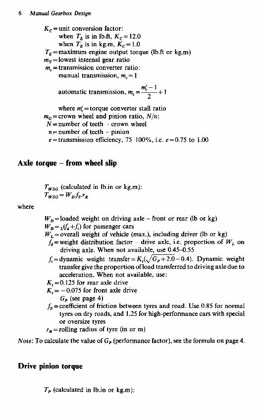
K , = unit conversion factor: when TE is in lb.ft, K,= 12.0 when TE is in kg.m, K , = 1 .O
TE = maximum engine output torque (1b.ft or kg.m) m,=lowest internal gear ratio m, = transmission converter ratio:
manual transmission, m, = 1
m:-l 2 automatic transmission, m, = - + 1
where mf= torque converter stall ratio m,=crown wheel and pinion ratio, N l n : N =number of teeth - crown wheel n = number of teeth - pinion e = transmission efficiency, 75-100%, Le. e=0.75 to 1.00
Axle torque - from wheel slip
T,,, (calculated in Ib.in or kg.m): TWSG= WDLfS*rR
where
W,=loaded weight on driving axle - front or rear (lb or kg) W, = & +f) for passenger cars W,=overall weight of vehicle (max.), including driver (lb or kg)
f d = weight distribution factor - drive axle, i.e. proportion of W, on driving axle. When not available, use 0.45-0.55
f = dynamic weight transfer = K , ( J m - 0 . 4 ) . Dynamic weight transfer give the proportion of load transferred to driving axle due to acceleration. When not available, use:
K , =0.125 for rear axle drive K , = -0.075 for front axle drive
G, (see page 4) f, = coefficient of friction between tyres and road. Use 0.85 for normal
tyres on dry roads, and 1.25 for high-performance cars with special or oversize tyres
r , =rolling radius of tyre (in or m)
Note: To calculate the value of G , (performance factor), see the formula on page 4.
Drive pinion torque
T, (calculated in 1b.in or kg.m):

Crown wheel and pinion 7
n T --.TG
P - N where :
n =number of teeth - pinion N = number of teeth - crown wheel
T , = axial torque - drive gear: Use TpFG (see page 4) or TPMG (see page 5 ) or TwsG (see page 6 )
Stress determination and scoring resistance
Checking the strength of the gears, using the new higher torques, should be carried out by checking the pair of gears for their resistance to tooth breakage and surface failure. Resistance to tooth breakage is normally dependent upon the bending stress occurring in the root area of the tooth, and the resistance to surface failure usually depends on contact stress occurring on the tooth surfaces, while the scoring resistance is measured by the critical temperature at the point of contact of the gear teeth.
These values can be obtained using the appropriate Gleason formulae. Modified versions of such formulae are given in detail in the following pages.
Bending stress
The dynamic bending stresses in straight, spiral or hypoid bevel crown wheels and pinions manufactured in steel are calculated using the following formulae:
Calculated dynamic tensile stress at the tooth root:
Si (in lb/in2 or kg/mm2)
K,. T.Q. K O . K si = K"
where
K Q = unit conversion factor: where torque T is in lb.in, K , = 1 .OO where torque T is in kg.m, K,=0.061
T = transmitted torque (1b.in or kg.m): (a) vehicle performance torque (b) axle torque (maximum engine torque) (c) axle torque (wheel slip)
given on pages 8-15 inclusive
axle-drive gears
Q =geometry (strength) factor, calculated from the Gleason formulae
K,=overload factor - usually assumed to be 1.00 for passenger car

8 Manual Gearbox Design
K , =load distribution factor: pinion overhung mounted, 1.10 pinion straddle mounted, 1 .OO
axle-drive gears &=dynamic factor - usually assumed to be 1.00 for passenger car
Using the formulae given and the relevant torque values, the dynamic tensile stress should always be calculated for both the crown wheel and pinion in each application.
Contact stress
In the same way, a modified equation for the contact stress in straight, spiral or hypoid bevel, crown wheels and pinions manufactured in steel has also been arrived at and is given in the following pages.
Calculated contact stress:
S, (in lb/in2 or kg/mm2)
where
K, = unit conversion factor: when torque T is in lb.in, K,= 1.00 when torque T is in kg.m, K,=0.006 55
Z , = geometry (contact) stress, which can be calculated by using the Gleason formula given later in this chapter (see page 9). P denotes the use of stresses and torque values relevant to the pinion: since the contact stress is equal on crown wheel and pinion, it is only necessary to calculate the value for the pinion
T,=maximum pinion torque for which the tooth contact pattern was developed (in 1b.in or kg.m)
C, =overload factor - for passenger car axle-drive gears or differential gears, the overload factor is usually assumed to be 1.0
C , =load distribution factor: pinion overhung mounted, 1.1 pinion straddle mounted, 1 .O
axle-drive gears
value of Tp
C,=dynamic factor - usually assumed to be 1.00 for passenger car
Tpc = operating pinion torque (in 1b.in or kg.m); this should not exceed the
The formula for the calculated contact stress assumes that the tooth contact pattern covers the full working profile without concentration at any point under full load.
The cube root term in the formula adjusts for operating loads which are less than the full load.

Crown wheel and pinion 9
Calculation of geometry factors ‘Q’for strength and ‘Zp’ for contact stress:
Using the following formulae, the values for ‘Q’ and ‘Zp’ can be calculated,
where
yK .-._.- RT F E ‘d Q = - M N K i R F P ,
and
The values required to solve the equations for ‘Q’ and ‘Zp’ can be calculated using the following data and formulae:
A, = outer cone distance a, =large end addendum bo = large end dededum D = large end pitch diameter F = actual facewidth (may be different on both members) F’=net facewidth (use smallest value of F) N = number of teeth P , =large end diametral pitch R , = tool edge radius
to =large end transverse circular tooth thickness 6 = dedendum angle r = pitch angle r, =face angle 4 = normal pressure angle $ =mean spiral angle
In addition to these known data, the following calculated quantities will be
Subscripts ‘P’ and ‘G’ refer to pinion and gear, respectively, and ‘mate’ refers to required for both gear and pinion.
the value for the mating member.
A = A, - 0 . W = mean cone distance a = To - r = addendum angle a = a, - OSF‘tan a = mean addendum b = bo -0.SF’tan 6 =mean dedendum
k = 3.2NG + 4 . 0 N p
N G - N P
A P - 0 Pd =mean diametral pitch
* - A
II
‘d p = - = large end transverse circular pitch
A pa = - p cos $ =mean normal circular pitch
A ,

10 Manual Gearbox Design
-mean transverse pitch radius D A R = - . - - 2 COS r A,
R R -mean normal pitch radius - cos2 *
R,, = R, cos 4 =mean normal base radius RON = R, + a = mean normal outside radius
A t = - to cos II/ =mean normal circular tooth thickness
A ,
Ap = Ja- R, sin 4 Z, = App + Ap, = length of action in mean normal section
F' 2 - -
A0 K'=A, 2(1-;)
F [ - Z N mp = - = transverse contact ratio P 2
For straight bevel and Zero1 bevel gears, the transverse contact ratio must be greater than 1.0, otherwise the following formulae cannot be used:
=face contact ratio 7L
mF =
m, = d m = modified contact ratio
P 3 = P 2 (57 [ 1 -~+&++JG] 2 2m,-Kmp pinionlgear m,
when m, is less than 2.0
when m, is greater than 2.0 p 3 =distance in mean normal section from the beginning of action to the
point of load application

Crown wheel and pinion 11
when m, is less than 2.0
Fm, x, =- when m, is greater than 2.0
Km, x i =distance from mean section to centre of pressure, measured in the
lengthwise direction along the tooth CRN = RNp + RN,
p , + ~ ~ , s i n ~ - - - J ~ R ~ , - R ~ , ) mate tan 4,, =
RbN
tan 4,, = pressure angle at point of load application
8, = rotation angle between point of load application and tooth centre- line
4 N = d)k
= angle which the normal force makes with a line perpendicular to the tooth centre-line
R,=-- RbN -radius in mean normal section to point of load application ‘Os 4N on tooth centre-line
AR, = R, - R, = distance from pitch circle to point of load application on tooth centre-line
=fillet radius at root of tooth
when m, is less than 2.0
Fm, m,
F, = - when m, is greater than 2.0
F, = projected length of the line of contact contained within the ellipse of tooth bearing in the lengthwise direction of the tooth
y2 = b- RT
x,=:+ b tan d ) + RT(sec 4 -tan 4) 2
cos J / b =cos ~ J C O S ’ J/ + tan2 4 q2 = 2: cos4 Jl,, + F’ sin’

12 Manual Gearbox Design
R sin 4 cos2 * b section
p=-- -radius of profile curvature at pitch circle in mean normal
With the preceding values calculated, it is now possible to determine the values required to calculate the equations for the geometry factors for strength and contact stress.
The contact stress value is at an assumed distance 'f' from the mid-point of the tooth to the line of contact.
The value of 'f' should be chosen to produce the minimum value of Z,, which corresponds to the point of maximum contact stress, and may be found by trial. For straight bevel and Zero1 bevel gears, this line of contact will pass close to the lowest point of single tooth contact, in which case distance
where f=distance from mid-point of tooth to line of contact at which Z,, the
contact stress geometry factor, will be a minimum A
pN =-p cos * cos 4 A0
=mean normal base pitch q: =$-4f 2
z0=-+ + - 4%
PI = P P + Z o
Pz = Pc - 2 0
ZN F'.ZWq, sin +b Z;.fcos2 i,hb
2 k.q2 v2
The remaining values are calculated from the following formulae before the calculations for the geometry factors for strength and contact stress can be completed:
YK = tooth form factor
Within the tooth form factor are incorporated the components for both the radial and tangential loads and the combined stress concentration and stress correction factor.
Since the tooth form factor must be determined for the weakest section, an initial assumptipn must be made and by trial a final solution obtained.
X,=assumed value; for an initial value, make X , = X , + y 2
x, = x, - xo z1 = y 2 cos 8-X, sin 8 z2 = y 2 sin 8 + X, cos 8
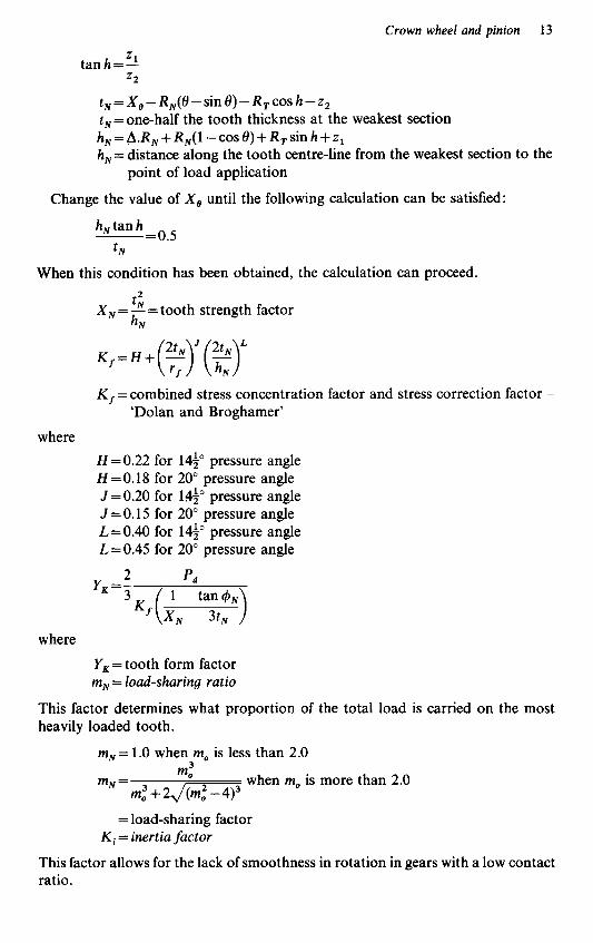
Crown wheel and pinion 13
Z1 tanh=- 22
t , =X,-R,(O-sin 0)-R,cos h - z , t , = one-half the tooth thickness at the weakest section h, = A X , + R,(1 -cos 0) + R, sin h +z, h, = distance along the tooth centre-line from the weakest section to the
point of load application
Change the value of X, until the following calculation can be satisfied:
h, tan h t ,
-- - 0.5
When this condition has been obtained, the calculation can proceed. 2
tN h,
X , = - = tooth strength factor
2t , 2t , . ,=H+(,) (G) K = combined stress concentration factor and stress correction factor -
'Dolan and Broghamer'
where H = 0 . 2 2 for 14p pressure angle H=0.18 for 20" pressure angle J = O . ~ O for 14i0 pressure angle J=O.15 for 20" pressure angle L = 0.40 for 142 pressure angle L=O.45 for 20" pressure angle
YK -_ 2 p* -
3
where
YK = tooth form factor m, = load-sharing ratio
This factor determines what proportion of the total load is carried on the most heavily loaded tooth.
mN = 1 .O when m, is less than 2.0
when m, is more than 2.0 m: m - N- m: i- 2, / -
= load-sharing factor Ki = inertia factor
This factor allows for the lack of smoothness in rotation in gears with a low contact ratio.

14 Manual Gearbox Design
2.0 m,
Ki = - when m, is less than 2.0
Ki = 1 .O when m, is more than 2.0
R, =mean transverse radius to point of load application
=inertia factor
=mean transverse radius to point of load application
Note: Use the positive sign for the concave side of the pinion tooth and mating convex side of the gear tooth. Use the negative sign for the convex side of the pinion tooth and mating concave side of the gear tooth. That is, use the positive sign for a left-hand pinion, driving clockwise when viewed from the back, or a right-hand pinion, driving anti-clockwise.
Use the negative sign for a right-hand pinion, driving clockwise, or a left-hand pinion, driving anti-clockwise.
The positive sign should always be used for straight bevel and Zero1 bevel gears.
F, = effective facewidth
This quantity evaluates the effectiveness of the tooth in distributing the load over the root cross-section.
F - F K x AFT = - + 2 -the -
2cos* ' cos* toe increment
F - F , X, AFH = - - - = the heel increment
2cos* cos*
AFT F, = hN cos 1,4 tan-' -+tan- ( hN
=effective facewidth
S=length of line of contact
The length of the line of contact at the instant when the contact stress is a maximum will be:
F.ZN,vl COS $a
v 2 S =
=length of line of contact po =relative radius of curvature
This factor expresses the relative radius of profile curvature at the point of contact when the contact stress is a maximum.
P 1 4 2 Po=-
P l + P 2
=relative radius of curvature

Crown wheel and pinion 15
When calculating the contact stress use the following formula for the load-sharing ratio:
mN = Load-sharing ratio - Contact stress
This method of calculating this factor determines what proportion of the total load is carried on the tooth being analysed at the given instant.
+J[1: - 8 P N ( 2 P N + 2 f ) 1 3 + J [ q : - 8 P N ( 2 P N - 2 f ) 1 3 When any quantity under the radical in the above formula is negative, make the
value of that radical equal to zero. v3 mN = f = load-sharing ratio 1 2
From the foregoing formulae it is possible to calculate the size of crown wheel and pinion necessary to withstand the loads to be applied.
With the size of crown wheel and pinion fixed, the next problem in the transmission design to be solved is to finalize the crown wheel and pinion ratio. This must ensure that the maximum road speed or output shaft speed required can be achieved for a given number of engine revolutions per minute.
The crown wheel and pinion ratio can be calculated using the following formulae: Crown wheel and pinion ratio
- No. of teeth (crown wheel)
- Engine (rpm) x 60 x 2n: x Rolling radius (road wheel)
- No. of teeth (pinion)
- Road speed (mph) x 1760 x 36
where the rolling radius is in inches.
The second formula assumes that the internal ratio in the gearbox is a 1 : 1 ratio or a direct drive from the engine. Therefore, when using any other ratio the necessary modification must be incorporated into the formula. Having fixed the crown wheel and pinion ratio and subsequently the number of teeth on both components, the final factor in finalizing the size of the crown wheel and pinion must be the choice of material and the heat treatment to be used. This will have a large effect on the strength and surface durability of the two mating gears.
Having finalized the size of both the crown wheel and pinion, the first lines of the transmission or gearbox layout can be drawn. The guidelines usually given to the transmission designer include the relative position of the engine crankshaft centre-line to the gearbox output shaft centre-line. From these dimensions the centre-lines of the gearbox input shaft, the pinion shaft and the crown wheel, together with the output shaft, can be arrived at. Using the internal gear ratios required for the application, it should be possible to fix a position for the intermediate shaft, which usually carries 50% of the internal gears.
This position can be rigidly tied down in a two-shaft gearbox, given the engine installation location relative to the gearbox output shaft or axle drive shaft centre-line, the ground clearance required and the necessary clearances between the engine, gearbox and other surrounding components.

3
Internal running gear
With the position of the intermediate shaft provisionally fixed, the approximate centres between the intermediate shaft and layshaft/output shaft can be measured. Using this dimension and given the gearbox input torque, the tooth size - either diametral pitch or module, which is dictated by the gear tooth strength, the number of teeth and the gear ratios - can be calculated.
In an automobile application, the internal ratios in a gearbox, usually four, five or six, are selected to suit the required vehicle performance matched to the engine output torque, and in some instances, particularly high-performance sports cars and racing cars, to suit the driver’s individual technique and the type of circuits which they are to be used upon.
The size of the gear tooth, both the diametral pitch or module and the tooth width, will depend on the material used in the manufacture of the gears and any heat treatment incorporated, plus the required life expectation.
Shaft stressing for site
At this stage of the design, it is essential that a preliminary stressing programme is carried out to decide the size of the following gearbox components required to cope with the maximum gearbox input torque and allowing for the requisite safety factor:
1 Input shaft. The cross-sectional area should be checked both for shear and torsional stress, as well as the amount of deflection under full load. 2 Intermediate shaft. The cross-sectional area should also be checked both for shear and torsional stress, and if as in some gearboxes a gear ratio is included between the input and intermediate shafts, then the torque input must be calculated to suit. The amount of deflection in the shaft should be calculated using the load on the internal gear pair which is nearest to the half-way point between the intermediate shaft mounting bearings. 3 Output shaft. The cross-sectional area should be checked for shear and torsional ratio using the gearbox input ratio multiplied by any reduction in ratio between the input and intermediate shafts and the lowest gear ratio between the intermediate and output shafts.

Internal running gear 17
The following formulae can be used in the course of stressing the gearbox shafts:
1 Maximum shear stress for shafting,&
where torque is in 1b.in
(a) For solid circular shafts,
Torque or twisting moment x 16 f,= n x Shaft dia.3
(b) For hollow circular shafts,
Torque or twisting moment x 16 (Outs. dia.4-Ins. dia.4 1 Outs. dia.
(c) For square shafts,
Torque or twisting moment '=0.208 x Length of side of square3
(d) For rectangular shafts,
Torque or twisting moment x 9 '=2 x Length of long side x Length of short side2
2 Combined twisting and bending: where
f=extreme fibre stress due to bending Z=modulus of section for bending f, =maximum shear stress due to twisting and acting on the same plane as f Z, =modulus of section for twisting
d = diameter of shaft
(a) Maximum bending moment:
M=fZ
(b) Maximum twisting moment:
T = f , .Z,
(c) Maximum shear stress due to combined twisting and bending:
(d) Maximum principal normal stress:

18 Manual Gearbox Design
(e) Equiv. twisting moment due to combined twisting and bending:
nd3 - x 4 16 --
3 Angle of torsional deflection (in degrees) - solid circular section
- 583.6 x Twisting moment x Length between supports -
12000000xDia. of shaft"
4(a) Angular velocity at critical speed (rad/s)
4(b) Critical whirling speed of shaft
where
1 =length of shaft between supports (in) g = gravitational acceleration (386.4 in/s2) E = Young's modulus of elasticity I = moment of inertia of shaft cross-section (in") o = weight of shaft (lb per 1 in length)
a =distance between point of deflection and first support b =distance between point of deflection and second support
o1 =total weight of shaft plus weight of gear at point of deflection
4(c) Critical shaft speed
-_ ~ - 71 dwi.a2.b2
4(d) Amount of deflection
w,.a2.b2 3.E.I.l
-~ -
4(e) Calculation of the moment of inertia of shaft cross-section (in"):
for solid circular shafts,
R I = - x Dia. of shaft4
64
for hollow circulation shafts,
71 I = - x (Outs. dia." - Inside dia.4)
64

Internal running gear 19
Input shaft
In an automobile gearbox or transmission, the input shaft usually forms a direct link between the engine and gearbox, in the rear engine transmission layout in particular, when used in high-performance sports cars and racing cars, where it is designed as a quill shaft which is used to absorb some of the shock loadings which are created during racing-type standing starts and gear shifts. The input shaft must not only be designed to deal with the maximum engine torque while in normal drive, biit must also be capable of absorbing torques as high as five times the maximum. engine torque which can be generated in the lower gear ratios by ‘clutch snapping’ during gear changing, and when making racing-type standing starts. The material and heat treatment used for manufacturing this shaft will be chosen to suit the highest torques attainable and the application the transmission is to be used for.
Intermediate shaft
The intermediate shaft can be connected either direct to the input shaft or by using a pair of input gears to provide an input-step ratio. Where the connection is direct, the input load is the same as that used in the stress calculations for the input shaft; but if an input ratio is included, the input load will either be increased or decreased by the gear ratio, i.e. the input load increases if the speed is reduced and decreases if the speed is increased.
Having calculated the input load into the intermediate shaft, the stress and deflection calculations can be started using the formulae given earlier in this chapter.
The physical size of the intermediate shaft will be dictated by the following:
(a) the size of the input shaft and any connection used between the input and
(b) the stress loading and deflections in the shaft allied to the distance between the
(c) the material and heat treatment used in the manufacture of the shaft (d) the size of the gears and engaging dogs or synchromesh units required to cope
with the torque input (e) the bearing size is dependent upon the loading due to the forces generated by the
gears under full torque, and the sizes of the gears and selector units (f) the size of the gears and engaging dogs or synchromesh units is dependent on the
size of bearings used in free-running gears or the splines or serrations required if fixed gears are fitted Note: When stressing shafts with splines or serrations, it is usual to use the root diameter as the outside diameter in the stress calculations.
When all the above factors have been finalized, the intermediate shaft stress
intermediate shafts
supporting bearings, and the size of bearings required
calculation can be completed.
Output sha f i
The gearbox output is the final link in the internal running gear shafts. In a front-engined vehicle, where the engine and gearbox are built as a complete unit, the

20 Manual Gearbox Design
output shaft is usually in line with the engine crankshaft and the gearbox input shaft, whereas in a rear-engined vehicle, the gearbox output shaft is usually the pinion shaft. Whichever type of vehicle arrangement is used, the output shaft carries the mating gears of the internal ratios.
This means that the stress loading calculations and the factors dictating the physical size of the output shaft are exactly the same as those for the intermediate shaft.
Note: It must be remembered that when calculating the stresses and deflections in output shafts, the input load is that of the intermediate shaft multiplied by the maximum reduction in gear ratio between the intermediate and output shafts.
Using the formulae and information given on the previous pages of this chapter, the designer should be able to arrive at a stress loading sufficiently accurate to determine the sizes of the shafts required to cope with the input torque, but it must always be remembered that higher torque loadings can be generated within the gearbox due to outside influences.
Internal gears
Having arrived at the shaft sizes required to withstand the loadings in the gearbox application being considered, the next step is to finalize the internal gear ratios and the number of gears required to give the expected performance for the vehicle, taking into account the crown wheel and pinion or final drive ratio.
In a passenger car transmission, the gear ratios are fixed to suit general purposes, using as a basis the required car maximum speed, along with the engine maximum revolutions, both of which are usually fixed in the early stages of the vehicle design.
Using the maximum vehicle speed required, along with the engine maximum revolutions, then with a gearbox in which the top gear ratio is 1 : 1 or a straight through drive and given the tyre rolling radius, the crown wheel and pinion or final drive ratio can be calculated.
Where a gear-driven top gear ratio is fitted, then having calculated the size of tooth required and the total number of teeth on the gear pair, which is fixed by the centre distance between the intermediate and output shafts, the top gear ratio can be finalized. It should be noted that in the interest of sound engineering and good gear design practice, the total number of teeth in a gear pair should, wherever possible, be an odd number which is not divisible by any other number, so that when the gear ratto pair is calculated an unequal number of teeth is called for on the gears. This odd number of teeth ensures that each gear pair includes a ‘hunting’ tooth which ensures that any one tooth on one gear does not consistently engage with the same tooth on the mating gear, which would mean that any machining flaw, tooth profile error, tooth spacing error or eccentricity in the gear would be exaggerated under load and consequently result in early tooth failures.
By plotting a graph of road speed against engine revolutions, and using the top gear ratio speed as a fixed point, it is possible to arrive at the lowest first-gear ratio permissible. This lowest gear ratio can be fixed using the total number of teeth per ratio, which was selected earlier, and using the calculated shaft sizes, the smallest gear with the lowest number of teeth that will fit on the intermediate shaft, i.e. the

Internal running gear 21
driving gear, can be fixed. Knowing the number of teeth on this smallest gear, the lowest gear ratio can be calculated and plotted on the road speed/engine revolution graph.
Knowing the highest and the lowest gear ratios, with the total number of teeth, then all the intermediate ratios possible between these two gears can be calculated using the same parameters that were used to calculate the highest and lowest ratios. These intermediate ratios should now be plotted on the road speed/engine revolution graph and finally a line should be drawn across the graph at the maximum engine revolutions per minute to be used; this is usually slightly higher than the revolutions at which the engine produces maximum torque. Utilizing this graph, the selection of the gear ratios can be commenced, by using the maximum speed required in first gear; then the ratio can be marked and from the point that this intersects the maximum engine revolutions line, a vertical line should be drawn on the graph.
The torque ranges of the types of engine the transmission is being designed for will permit a point to be fixed on this vertical line at the engine revolutions for maximum torque, and at this point the nearest calculated intermediate gear line should be marked on the vertical line, i.e. the mark should be within the engine usable torque range. This vertical line represents the fall in engine revolutions per minute when changing down from second gear to first gear. Using the point where the vertical line crosses the maximum torque line, and joining this with the point on the engine maximum revolution horizontal line coinciding with the maximum road speed required, will provide a guide-line for the bottom points of other intermediate ratios. The ratio nearest to but above the minimum engine revolution torque band-line must be used as the first approximation for second gear, unless second gear has to be fixed to meet some specific target, such as zero to a given miles per hour where only one gear change is allowable.
From the point where this second ratio touches the maximum engine revolution line, a vertical line should be drawn down to the minimum engine revolution/torque range line. This will approximate the lower starting point of the engine revolutions in third gear in the same way that second gear was fixed.
This process should be continued and the approximate gear ratios modified until the required number of gears have been selected. The gear lines and vertical lines will form the shape of a Christmas tree and the vertical lines indicate the drop in engine revolutions in between gear changes. The higher fall in engine revolutions will occur in between first and second gear, and the lowest fall in revolutions should occur when changing up to top gear. This formation results in quicker, smoother acceleration when changing up through the gears.
When calculating the road speeds in the gear ratios, it is important to remember that the crown wheel and pinion ratio is included as shown in the following formula:
Engine rpm x 60 x 2n x RR Tp Tdriving Road speed (mph)= x-x-
36 x 1760 TW Tdriven
where
RR = rolling radius road wheel (in) Tp = no. of teeth - pinion
22 Manual Gearbox Design
T, = no. of teeth - crown wheel Tdriving = no. of teeth - driving gear internal gear ratio Tdriven = no. of teeth - driven gear internal gear ratio
Note: When plotting the road speedfengine revolution graph, the road speed in miles per hour should be plotted horizontally and the engine revolutions per minute vertically.
Having finalized the sizes of the dynamic running gear, the crown wheel, pinion, input shaft, intermediate shaft, output shaft and internal gear ratios, the next stage in the design is to settle on the type oflubrication system to be used and the system to be used for selecting the individual integral gear ratios.
Lubrication system
Lubrication of the gears was briefly mentioned in Chapter 1 and will be more fully discussed in a later chapter, but at this point it must be emphasized that the lubrication system must be part of the early planning in the initial stages of the gearbox design and designed to cater for the particular gearbox application, the loads expected on the gears and the life and efficiencies required from the gearbox. It is only by a full and thorough assessment at this stage of the design project that the best form of lubrication system can be designed to suit, to provide the most efficient running gear train possible.
The lubrication system can either be recirculating, fully pressurized or a splash type, and these systems may be either sealed systems within the gearbox casing or have an external oil tank or reservoir and radiator or cooler. Whichever lubrication system is decided upon, it is only in the initial design stage that the best positions can be fixed for such items as the oil inlets and outlets, the oil feed jets, the oil pump and filter, the oil filler and drain plug and, probably the most important item, the gearbox breather, in order that the best possible results can be achieved. In the past few years, the problems of lubrication in gearing and the rest of the engineering industry have been tackled as an individual entity in the research field and rapid improvements have been made as a result of this, which have resulted in vastly improved component lives and much higher efficiencies, especially in the more heavily loaded transmissions running at high speeds. With the lubrication system in hand and the study of the type of system finalized in line with the service requirements of the transmission, the next stage of the design is to decide the type of gear engagement to be used.
Gear engagement
Current standard passenger car manual gearboxes use various types of synchro- mesh units which ensure that a smooth gear change is possible when the vehicle is in motion. The synchromesh unit consists of a system of baulk rings, tapered conical sleeves and engaging dog sleeves which ensure that the gear and engaging dog sleeve rotate at compatible speeds during the gear change process. Some passenger cars do not have synchromesh on first gear, the thinking behind this being that the selection

Internal running gear 23
of first gear when fitted with synchromesh can be difficult under certain circumstan- ces with the vehicle stationary. This practice is gradually being dropped in the motor industry because of the problems when changing down into first gear with the vehicle in motion, which could be overcome by the driver double-declutching.
As the synchromesh system is not deemed to be quick enough, due to the momentary pause in the baulk ring reaction in bringing the two engaging components into phase, high-performance sports cars in some instances and most racing cars -use a gearbox fitted with face dog engagement systems instead of synchromesh, which provides the driver with a quicker, more responsive gear change and a closer feel for the engine response and performance.
The face dog system can be designed into a small area, which helps to keep the overall length of the internal gear pack down to a minimum length and provides a most positive gear change. This is made possible by leaving an angular clearance of between 0.100in and 0.150in between the face dog and the engaging slot to ensure ease and speed of engagment, with the resultant quick, clean gear change.
With this angular clearance it is essential that the design detail ensures full face contact between the dog face and the side of the mating slot when the radial clearance is taken up; this rule applies to the full complement of engaging dogs.
The angular clearance is usually designed by machining the dogs on the free-running gears with parallel faces, whereas the slots in the engaging dog ring are machined at an angle calculated to provide the full face contact when the clearance has been taken up in both directions of rotation. This means that in a multi-ratio gearbox, the most straightforward machining operation is carried out on the majority of components, since one engaging dog ring, with the engaging slots and their faces machined at an angle on both sides of the dog ring, is used to engage two gear ratios. The free-running gears are mounted on either needle roller or sleeve-type bearings and are usually in constant mesh with their respective mating gears. Though the engaging dog ring is carried on a sleeve with internal splines or serrations to locate it on the shaft and an external spline or serration which mates with an internal spline or serration in the dog ring, and is raised above the outside diameter of the needle roller or sleeve-type bearing, the inside diameters of these bearings run on plain portions machined at each end of the engaging dog sleeve.
Thus, when assembled, two pairs of internal gears complete with bearings and an engaging dog ring are mounted on one engaging dog sleeve, whose length ofexternal spline allows the dog ring to be placed in a central position with a minimum clearance of 0.025 in between the engaging dogs and the faces of the engaging slots on both of the free-running gears when they are in their closer relationship.
The dogs on the face of the free-running gears are designed in such a way as to ensure that they overhang the external splines or serrations on the engaging dog sleeve for their full length, thus ensuring that the splines or serrations in the bore of the engaging dog ring are always in full contact when moved from the neutral position to the fully engaged position.
The face dogs and the engaging slots are also machined with a reverse angle along each of the side faces to provide a form of dovetail joint; this angle is usually between 5" and lo" and must be machined accurately to provide a full face contact. The angle is used to hold the dogs in engagement when under load, and the angle used will be dependent on the following:

24 Manual Gearbox Design
(a) the transmission loadings (b) the speed of gear change required (c) the driver’s gear change reaction and technique (d) the designer’s past experience
The design and back-up development of a synchromesh unit is expensive and complex, whereas proprietary units are usually available fully developed and tested. Such units are marketed by various companies, especially the leading gearbox manufacturers, but some major car companies design and use their own synchro- mesh units and gearboxes to suit the vehicles they make. Other types of gear engagement have been and are still used, but these are found in a small percentage of the transmissions used in motor vehicles.
The next stage of the gearbox design is to decide the method to be used to move the engaging dogs, thus allowing each individual internal gear ratio to be selected or engaged from the outside of the gearbox. For each pair of internal gear ratios, or any odd ratio left after the remaining ratios have been grouped in pairs, one engaging dog ring with dogs or synchromesh tapers on each face are required to facilitate gear selection.
Therefore, in a vehicle gearbox with five forward gears and a reverse gear, three engaging dog rings are required. The first ring will engage reverse and first gear, the second ring will engage second and third gear, and the third ring will engage fourth and fifth gear.
However, in a gearbox with four forward gears and a reverse gear, three engaging dog rings will still be required, the first one being used to engage reverse gear, the second to engage first and second gears and the third to engage third and fourth gears.
The two most popular methods used to move the engaging dog rings into and out of mesh with the face dogs or synchromesh tapers on the free-running gears during the past are described below:
1 A raised flange is machined on the outside diameter of the engaging dog ring centrally between the face dogs or synchrotapers on either side. This flange is raised above the outside diameter of the face dogs or synchrotaper, to allow a grooved semicircular fork to be located on the flange and provide the backward and forward movement to the engaging dog ring. The internal diameter of the semicircular fork should provide a location on the outside diameter of the face dogs. The groove in the fork should be a close-running fit on the sides of the raised flange, and the outside diameter of this flange is kept clear of the bottom of the groove in the fork. 2 The second method has a groove machined in the outside diameter of the engaging dog ring into which the semicircular selector fork fits. This method has proved to be the least popular because it results in the overall length of the internal gear pack being greater than when using method number one, which means using larger diameter shafts and bearings due to the increased location bearing centres.
Recently, both electric and hydraulically actuated gear-change systems have been tested and used on passenger cars, but not to any extent as yet on the high-performance sports car or racing car.
In both of the methods described above, the semicircular selector fork is carried

Internal running gear 25
on a selector shaft; therefore, for each engaging dog ring and pair of internal gear ratios used in the transmission design, there will be one selector fork and selector shaft. However,. in recent years some designs have located all the selector forks on one selector shaft. When one selector fork is used on its own individual selector shaft, the fork is fixed to the shaft using various methods. These must allow the position of the selector fork to be adjustable so that it can allow the engaging dog ring to be centralized between its two gears which are to be engaged. The methods used to locate the selector fork on its shaft include splines, serrations, pinch bolts, dog point screw, a key and groove or a lock-nut which pulls the selector fork against a shoulder or another lock-nut. Whichever method of location is chosen, apart from providing adjustability, it must when fitted be absolutely positive and the selector fork locked in position with no movement along the selector shaft.
Each individual selector shaft has a jaw-type slot positioned along its length in a suitable position, so that a striker arm or pivot lever may be mounted in the gearbox casing to suit the location of the gear change lever. The slots in the selector shafts should be in line when the engaging dog ring is in neutral position. With the shafts all in neutral position, the striker arm must be able to swing freely from one slot to another, even allowing for the fact that the side clearance is kept to a minimum. The striker arm location in the gearbox is decided by a combination of (a) the overall vehicle layout, (b) the line of the linkage to the gear change lever, and finally (c) the position of the selector shafts within the gearbox. These selector shafts are located adjacent to the shaft carrying the free-running internal gears and the engaging dog rings.
The selector shafts should be positioned as close to the outside diameter of the largest idler gear to be used, as permitted by the outside diameter of the selector fork location boss when mounted on the selector shaft. The selector shafts should also be kept in line, in order that the striker arm movement can be kept equal about the central position and to allow for the simplest form of interlock system, which will be explained later.
The striker arm movements are forward and backwards to engage and disengage each gear, and sideways through the jaws on the selector shafts to permit the required shaft to be engaged. This sideways movement is controlled by two factors: first, the design and method of assembly of the selector shaft with their jaws and selector forks and, secondly, by the vehicle application and design. That is, in a high-performance sports or saloon car in which the best speeds are to be exploited, the sideways movement is kept as low as the design will permit - approximately 12p of movement between adjacent selector shafts - whereas the forward and backward movement is fixed by the amount of clearance between the engaging dog rings and the face dogs on the free-running gears when in a neutral or disengaged position and the depth of the face dogs on the gears, which are designed to cope with the maximum torque to be transmitted and ensure that, when engaged, sufficient depth of the reverse-angled face is in contact to make sure that the engaging dog cannot jump out of engagement when under load.
The two outer selector shafts should incorporate, in the design of their jaws for the striker arm, a means of restricting the movement of the striker arm to ensure that it cannot move clear of the jaws when they are being engaged.

26 Manual Gearbox Design
Interlock system
The next stage of the gear selector system design is to provide a means of locking the selected gear in position, which also ensures that only one gear can be selected at a time. Probably the most common method used to provide location, either in neutral or the engaged position, is to use spring-loaded balls or spherical-ended plungers, mounted in a suitable position in the gearbox casing, which engage in grooves or slots machined in the selector shafts. With all the engaging dogs in neutral position, the spring-loaded balls should be in the centre groove, with one on each side, which is located by the spring-loaded balls when the gear is fully engaged. This type of location prevents the engaging dog moving due to vibration or any end loading while in neutral or the engaged position.
The problem of ensuring that only one gear can be selected at a time can be tackled in various ways, some of which are as follows:
(a) interlocking plates at the gear change lever (b) a gear change gate at the gear change lever (c) a gear change system with moving plates arranged to allow one gear selection
However, probably one of the simplest and most effective systems that I have come across during my time working on transmissions is the one introduced by Signor Valerio Colotti on his six-speed Formula One racing gearbox which was used with the I$-litre engines.
This system requires the selector shafts to be kept in one line, and in a gearbox with three selector shafts. The centre shaft should have a hole through it, of suitable diameter to provide a sliding fit for a single needle roller. This hole should be in line with the centre-line through the three shafts, when the striker arm is free to swing between the selector shaft jaws in the neutral position. In line with this hole and on the side facing the hole, both outer selector shafts have a counterbore. Both ends of the hole in the centre shaft are also counterbored. The interlock system is activated by fitting a needle roller in the hole in the centre shaft and, in a hole drilled along the centre-line of the three shafts, in the gearbox casing, a ball located between the centre selector shaft and each of the two outer ones. The selector shaft centres, the ball diameter and the length of the needle roller, together with the selector shaft diameter and size of counterbore, are chosen so that if one of the two outer shafts is moved the ball moves out of the counterbore onto the outside diameter of that shaft and into the counterbore in the centre shaft. This ball pushes the needle roller through the centre shaft and thus the second ball is pushed into the counterbore in the other outer shaft; therefore, both the centre shaft and the second outer shaft cannot move, provided that the balls are a close fit in the drilled hole in the gearbox casing.
Alternatively, if the centre selector shaft is moved, then both balls move onto the outside diameter of this shaft into the counterbores in the two outer shafts which prevents the movement of both these shafts. In this position, the needle roller length should be retained within the diameter of the centre selector shaft, thus leaving it free to move. The next move is to drill a hole in the gearbox casing which passes through the centre-line of the selector shaft holes in line with the counterbores in the selector shafts when they are in neutral position.
movement at a time

Internal running gear 27
This drilled hole must be a fairly close fit for the size of ball used, and at the outer surface of the casing the hole must be plugged to prevent oil leakage. By carefully choosing the selector shaft centres, the depth of the counterbores and the shaft diameters, then standard size balls and needle roller may be used, and will provide an absolutely positive yet inexpensive interlock system.
Reverse gear
Next on the list must be the provision of a reverse gear. This can be obtained by using an idler gear, running in a train between a gear mounted and fixed onto the input shaft and another gear mounted and fixed onto the output or pinion shaft. This gear train will thus reverse the rotation of the output shaft, as against the rotation obtained by a direct drive between gears mounted on the input and output shafts. One of the three gears in the reverse gear train must be able to slide sideways into and out of mesh by the movement of a selector fork. If the reverse selector fork is mounted on a separate selector shaft, this shaft must also be controlled by the interlock system in the gearbox.
Dzperential
The final stage of the internal running gear design is to decide the type and size of differential unit required for the particular gearbox application, and the types and sizes of bearings and oil seals. To decide these, it is essential that the bearing loads and rubbing speeds of the seals are calculated, and bearings and seals selected to cope with these.
Many types of differential units are available and the type chosen will depend on the following:
(a) the cost of the unit (b) the type of transmission (c) the ultimate use of the transmission (d) the results required from the transmission in use
The majority of passenger cars use a bevel or pinion type of differential, both of which allow differential movement between the two wheels on a driven axle when driving round a curve or if one wheel is on soft ground. Due to the gear movement in this type of differential being unrestricted, very unpredictable results can be produced when starting off or driving on soft or slippery ground, as the wheels are free to rotate with no appreciable resistance, thus resulting in the wheels digging into the soft ground, or spinning on slippery or icy surfaces instead of propelling the vehicle forward.
On surfaces with loose gravel, potholes or thick mud, the road wheels will have a tendency to bounce and skid. This tendency will be increased due to the low internal resistance of the differential. With such movement occurring on one wheel, the end result is wheel-spin, which creates an unbalanced drive which makes the vehicle difficult to control and could result in violent skidding. The bevel or pinion type of

28 Manual Gearbox Design
differential consists of either a spider with two trunnions carrying two differential pinions, or with four trunnions carrying four differential pinions, each pinion being backed by a thrust washer. These pinions mesh with two differential side gears both backed by a thrust washer and all assembled into a housing or differential casing which is usually in two parts and bolted together after assembly. One half of the casing has a raised flange to which the crown wheel can be bolted.
Ordinary passenger car transmissions are usually fitted with a gear-type differential with two pinions, due to the low loads created within the differential by the engine input torque, which is multiplied by the internal ratio and the crown wheel and pinion ratio, this torque being passed through the differential casing and via the spider and differential pinions to the differential output gears, which are located on to the inner ends of the axle or wheel driving shafts using splines or serrations or other positive means. Therefore, if the differential gearing is of the constant velocity type, either of involute tooth form or any equivalent, the torque at the differential will, regardless of ground conditions, always be equally divided between the two drive shafts.
This equalization of torque will be maintained regardless of any changes in external conditions or road surfaces. During straight ahead travel on flat, reasonably smooth surfaces, the differential assembly will tend to revolve as a single unit, with very little or no movement in relative rotation of the pinions on their trunnions and with both side gears rotating at the same angular velocity, which means that both road wheels are being driven at a similar speed. When rounding a curve or traversing uneven surfaces which results in one wheel rotating faster than its opposite number, the differential pinions will revolve on their trunnions, thus allowing for the differential speeds within the unit, but the equal torque distribution will still be maintained.
From this it can be seen that the ideal differential has not yet been perfected, for this would distribute torque equally to the two drive shafts under any condition of relative motion as dictated by ground speed, while at the same time it would not permit torque to be applied to one wheel in excess of the traction available without causing both wheels to slip simultaneously. Although this problem has not yet been fully solved, various improvements have been added to the pinion-type differential; these have led to the multi-disc self-locking differential. This type of differential has clutches, consisting of friction plates and Belleville spring washers, behind each of the side gears, which can be loaded by adding or removing friction plates to suit the vehicle requirements and the conditions in which it is expected to operate.
In a self-locking differential, the torque passed through the crown wheel and differential casing is transmitted through the spider and pinions into the two side gears, as in the normal pinion-type differential, but then the clutch plates which are fixed to the side gears and their intermediary clutch pressure plates make relative motion between the side gears and the differential casing, to which the clutch pressure plantes are fixed, more difficult. The amount of resistance built into these clutch packs comes from the load applied by the Belleville spring washer, which is a concave-type washer made of spring steel which can be used to apply variable pressure loading dependent on the thickness of spring steel used.
Various other forms of this type of differential are used on all different applications, but regardless of the actual method adopted to provide resistance to

Internal running gear 29
the movement, whether it be by using clutches or friction brakes or any other means, the basic concept of the self-locking differential remains the same.
Other forms of differential are used on special vehicle applications. For example, in the majority of high-speed sports cars and single-seater racing cars over the past few years, a self-locking type of differential has been fitted - in the majority of cases the cam and pawl type of differential. In this, the crown wheel is fixed to a flange on the differential driving member, which has eight equally spaced slots in a hub one side of the slange and a hub mounting to carry one of the differential location bearings on the opposite side. One road wheel is connected through a drive shaft or axle shaft to the inner differential member, which has 11 external cam contours, which are sited on assembly inside the hub with eight slots in the driving member. The opposite side road wheel is connected through its axle shaft to the outer differential member, which has 13 internal cam contours. These are sited on assembly over the hub, with eight slots in the driving member.
Driving force to the road wheels is through the crown wheel to the differential driving member, then through eight flat-sided pawls or slabs with radiused ends which fit in the eight slots and provide the drive to the road wheels through the internal and external cam profiles, on the inner and outer differential members. The numbers of cam profiles, 11 on the internal member and 13 in the external member, gives a total of 24 cam profiles, a figure that is exactly divisible by the number of driving pawls -eight. The hub on the differential driving member with the slots, the differential inner and outer members are covered by a differential casing which has a hub for the second differential location bearing plus a flange which is used for bolting the casing to the driving member and the crown wheel.
Relative movement between the differential inner and outer members is governed by the variation in rotational speed of the two road wheels, and the number of pawls and cam profiles were chosen to provide differentiation with sufficient accuracy relative to the revolution difference of the road wheels when cornering.
Drive to the differential inner and outer members is created by the wedging effect between the sliding pawls and the internal and external cam profiles, as the differential driving member is rotated.
A number of variations of the cam and pawl type of differential have been tried in the past, including the various uses of hydraulics to actuate the locking motion between the two differential driven members, but none of these variations has been very widely used.
Due to the various types of differential available, the designer must take into account the following points when making the decision on which differential type is to be used in the gearbox:
(a) the vehicle application and the types of terrain in which it is to be used (b) the cost of the differential unit relative to the overall transmission and vehicle
(c) the expected performance of both the differential and the transmission (d) the general usage of the transmission and the vehicle
A vehicle for general road use, e.g. a passenger car or light van, is usually fitted with a differential unit which is cost dictated, whereas the special-purpose and more sophisticated vehicles are fitted with differential units that give maximum efficiency
cost

30 Manual Gearbox Design
and tractive effort under all running conditions. This applies to such vehicles as the high-powered specially built and prepared rally cars and racing cars, while the off-road type of vehicle will be fitted with a heavy-duty special-purpose differential.
Bearing arrangement and casing
The next problem to be tackled in the internal running gear design is to choose the bearings most suitable for the design application. The bearings chosen must be capable of coping with the loads that will be encountered when the transmission unit is in use. The calculation of most of these loads is usually fairly straightforward, and the formulae often given in the catalogues that are available from the bearing manufacturers.
Each shaft in the transmission will require at least two bearings, one of which must be capable of taking thrust or side loading. The majority of road vehicle transmissions use a roller-type bearing and a ball bearing to each of its shafts. Exceptions to this type of arrangement are used and are dependent on the calculated loadings. It should be noted that the loads on the bearings are dependent on the type of gears used for the internal ratios. If straight-cut spur gears are used, radial loading will be the major problem, with thrust or end loading only being caused by malalignment of the shafts or by using crown or barrel cut gear teeth. However, if helical gears are used, the radial loading will be similar but the thrust or end loading is dependent on the helix angle of the gear teeth, and in recent years the efforts made to provide quieter gearboxes have come up with a contact ratio-total, exceeding 3.2, to minimize the noise, which has meant that larger helix angles are being used with the subsequent increase in thrust or end loading.
The bearing arrangement in a two-shaft racing gearbox consists of a ball-type bearing or similar type of thrust bearing as the location bearing at the front or engine end of the input or quill shaft, with the rear end of the shaft located into fitted splines in the forward end of the intermediate shaft. The forward end of the intermediate shaft is located in a ball-type bearing, either a single row or a double row, depending on the bearing loads. The rear end of the intermediate shaft is located by a roller-type bearing. This bearing arrangement means that the ball bearings are used to positively locate both the input and intermediate shaft and therefore the bearings must be positively located in a fore and aft direction both on the shafts and in the gearbox casing. However, the roller-type bearing has its inner track complete with rollers clamped on the intermediate shaft and its outer track positively located into the gearbox rear cover.
This bearing arrangement permits the internal gears to be assembled onto the intermediate shaft along with the shaft bearings, so that the assembly can be fully checked prior to the gearbox rear cover being fitted.
An alternative arrangement used in some gearbox designs has the bearing positions reversed, the roller bearing being at the forward end and the location ball bearing being at the rear end of the intermediate shaft, but this does lead to complications during the centralizing of the internal ratios on assembly, especially when checking the neutral position and fully engaged position of the face dogs. This arrangement means that the intermediate shaft is assembled into the gearbox rear

Internal running gear 3 1
cover and the internal gears must be threaded onto the intermediate shaft as the rear cover is fitted into position.
The pinion or output shaft has either a ball-type bearing, usually a double row type, or a pair of taper roller bearings mounted back to back directly behind the pinion gear, at the front of the gearbox casing, to provide the positive location for the pinion when it is meshed with the crown wheel. These location bearings must have the capacity to withstand the combined ‘thrust load’ from the pinion and crown wheel and the ‘radial loads’ from the pinion and the internal gear ratios.
The rear end of the pinion shaft is usually located by a roller-type bearing. This form of bearing arrangement for the pinion shaft ensures that the mesh of the crown wheel and pinion is not affected by any form of differential elongation between the materials used for the pinion shaft and the gearbox casing. The location bearings are positively locked in position by a threaded ring nut in some designs, so that no movement in the crown wheel and pinion mesh is possible while the internal gear ratios are being changed.
The crown wheel and differential assembly complete is also mounted between bearings, but due to the very high loads generated:
(a) by the thrust from the crown wheel and pinion mesh under load (b) the radial load of the crown wheel and differential assembly as a rotating mass (c) the radial load created by mounting the inner end of the axle or driving shafts
into the differential assembly, i.e. the inner and outer cam driven members
this means that great care must be taken when choosing the type of bearings and the method of mounting. As these total loads are calculated and the overall results carefully analysed, it will be found that the crown wheel and differential assembly have to be supported by a pair of taper roller or angular contact ball bearings, one on each side, which must cope with the total thrust load plus part of the radial load. The remainder of the radial load is carried by two ball bearings, one of which is located on the outside of the taper roller or angular contact ball bearings and is mounted on the driving shaft or axle shaft inner end. While the bearings supporting the crown wheel and differential assembly are being considered, it must be remembered that where a shaft passes through the outer wall of a gearbox casing, then the outer bearing supporting that shaft must have on its outside an oil seal to prevent oil leaking from the casing but still allow the bearings to be lubricated.
The size otthese oil seals will obviously be dictated by both the shaft and bearing sizes, but the oil seal must be capable of coping with the peripheral speed of the shaft and the flow of oil in its vicinity. The number of oil seals in a gearbox should be kept as low as possible in order to minimize the frictional losses incurred by the rubbing speed of the seal. In a two-shaft gearbox, it is possible to keep the number of seals down to a total of three - one at the input drive shaft plus one at each of the two output driving shafts. Having settled on the outline sizes of the seals, then the type of seals required at each point and the best material available for each application should be finalized. Help with these two problems is readily available free of charge, together with the seal delivery time, from most of the seal manufacturers.
The penultimate task to be tackled in the internal running gear design is to finalize the type of lubrication system required in the gearbox, so that the transmission

32 Manual Gearbox Design
system can achieve the targets that are set out for it. The lubrication system chosen will decide:
(a) whether an oil pump is required (b) if so, what type of pump - a gear type, a rotor type, a crescent gear type or an
(c) if a pump is required, where is the best position for it and how will it be driven (d) whether an oil filter is required and, if so, what type and where should it be
(e) whether the temperatures generated within the gearbox while in operation will
When making the decision on any of the above issues, the designer must carefully compare the cost of the components against the application, the expected results and, when applicable, the competitive selling price of the unit.
Having finalized the size of the internal running gear, the crown-wheel and pinion and the differential, the final layout of the gearbox can be commenced. Having drawn the internal running gear, the crown wheel and differential assembly and the pinion shaft in their relative positions, the design of the casings can be started. The casings must fulfil the following objectives:
(a) envelop the complete running gear and provide a leak-proof chamber for the lubricating oil
(b) provide adequate support for the bearings and oil seals to prevent movement or distortion when under load
(c) be of sufficient size, i.e. have reasonable clearance around the running gear, so that the lubricating oil can circulate freely
(d) include the necessary flanges or mounting points to allow the gearbox assembly to be connected to the power unit or engine and mounted into the vehicle chassis
(e) provide support for the whole selector mechanism, i.e. selector shafts and selector arm
(f) ensure that the overall outside or external shape of the gearbox casings fits into the space allocated for it in the vehicle chassis
(g) allow for access during assembly of the internal running gear to permit meshing checks and alignment checks to be carried out
(h) allow for access for in-service maintenance Note: The better such access is, the easier both build and maintenance costs may be kept as low as possible and assembly time kept to a minimum.
If the gearbox or transmission is being designed for an expensive sports or saloon car, or a racing car, then most probably the size, weight, type of materials used and the efficiency of the unit will usually take preference over the cost involved, but in commercial units cost must obviously always be carefully considered. However, the overall consideration in any gearbox design must always be reliability.
Having produced the final layout of the transmission, it is now possible to commence the detailed design drawings necessary for the manufacture of the components and the assembly drawings which can be used for both checking the detail drawings and as a guide for the technicians during the gearbox assembly procedure.
eccentric geroter type
positioned within the gearbox
require the use of a gearbox oil cooler

3 Lubrication of gears
Up to a few years ago the engineering world in general paid little or no attention to the gearbox lubrication system during the initial design stages. Thus when the internal running gear was finalized, lubrication became a major problem when the design of the gearbox casing commenced.
This was the method used by the majority of the gearbox manufacturing industry, and by approaching the problem in this way, consequently at this stage of the design a compromised lubrication system would be the final result. Then if at a later date some form of gear tooth surface failure occurred which was found to be the result of inadequate lubrication, the possibility of improving the lubrication system is limited and could result in a major redesign programme.
However, over the past few years a new scientific approach to lubrication problems has brought about major changes, not the least of these being the amount of advice and guidance that is available to the engineering designer. Probably the first major step was made when lubrication was introduced as a genuine research programme in selected universities in the UK and on the Continent. Such research programmes were given the title ‘tribology’, and were organized basically to examine methods of improving both the problems of applying the oil as a lubricant between moving surfaces, and what types of oil are available or if improvements are required for each particular application.
The university tribology research centres provide facilities for investigation and run courses for engineers to degree level in all aspects of lubrication and the problems that can be encountered in every application system used to supply oil to machinery in every known field of engineering. These university centres augment the research laboratories which most of the major oil companies own and which are equipped not only for the research and development of lubricants, but also to provide support and assistance with any lubrication problems that are encountered by their customers.
The work of the tribology centres and the oil companies has resulted in new approaches and efforts to improve the application of lubricants in the engineering industry. This applies especially in the gear and transmission fields, as tooth surface loads and rubbing speeds have increased as a result of the advances made in technology.
The result of the combined efforts made by both the universities and the oil

34 Manual Gearbox Design
companies means that the gear and transmission designers are now able to tackle lubrication problems knowing they are supported by numbers of highly trained lubrication engineers who can refer back to the results of numerous experiments. Therefore, the lubrication system in modern high-performance, heavily loaded gearboxes can now be decided upon and laid out in the initial stages along with the internal running gear which results in transmissions with much better efficiencies and longer lives.
Various methods can be used to apply the lubricant to gearing. Some are obviously more efficient than others, but depending upon the type of gearing being lubricated, if the correct system is used then the gears will operate successfully with very few failures.
The methods used to apply the lubricant to gears are covered in the following groupings:
1 Hand lubrication -where the lubricant is applied from an oil can or similar type of container. 2 Drip-feed lubrication - where the lubricant is applied from an oil container by means of a wick or a restricted oil feed pipe. 3 Bath-type lubrication or, as it is more commonly known, ‘splash lubrication’ - where the gear teeth are used as paddles to circulate the lubricant. 4 Pressure lubrication - where the lubricant is circulated by one of the various types of oil pump through oil galleries or oil pipes to oil jets which are directed at the gears.
Methods 1 and 2 are designated total loss systems and are usually restricted in use to open or partially enclosed gear trains, where the lubricant is neither recirculated nor recovered and, as a result of this feature, the amount of lubrication is kept to a minimum quantity of oil because of the rate of wastage. Total loss systems are usually applied to slow-running gears and often use a separate lubrication system for the bearings in the assembly.
Methods 3 and 4 are usually recirculating systems in which the oil is re-used, either by draining back into the oil bath or being pumped back into the oil galleries through an oil filter, from the bottom of the gearbox or the oil catch tank.
When making the choice as to the type of lubrication system required for a specific gear-train assembly, it is essential that a full study of the gear loadings, environment and life expectation is made and the differing forms of lubrication are fully understood.
Tribology is usually defined as the science and technology of interacting surfaces in relative motion and ofthe practices related thereto. The choice of this terminology was made to group together the fields of lubrication, frictional wear and bearing design with a view to obtaining an inter-disciplinary approach to these problems. Therefore, it can be seen that the tribology research groups cover a large proportion of the initial design work necessary on any new transmission design.
The National Engineering Laboratory at East Kilbride, near Glasgow, Scotland, which is part of the Ministry of Technology’s contribution toward the research into engineering problems, has played a leading role in the research field of tribology and

Lubrication of gears 35
the results of the many experiments carried out there are readily available to all branches of industry. The approach to tribology at East Kilbride has been described in the following words:
‘it brings together the expertise of the mechanical engineer, the metallurgist, the lubrication engineer, the designer and other engineers, thus enabling reliability and durability to be built into a design at the drawing board stage, instead of being approached by the trial and error method.’
Every designer is fully aware of numerous examples of failures and faults in machinery of all types, but it is not the occasional catastrophic failure that is economically significant, it is the level of failure that is almost taken for granted in prototypes by the engineering industry. These include the need for design modification that is carefully taken into account in pre-development costing, and also the failures that occur early in the machine life, and the reduced operating time and life of machines that have wear processes built into them. If all the available knowledge were fully utilized in the early design stages, both the direct and indirect costs of breakdowns and failures could almost be eliminated. This is one of the potential benefits of tribological foresight and teaching.
Some of the aspects that are embraced by the various tribology research groups include the following :
1 Environmental effects, ranging from climatic conditions to local effects such as hot oil tanks or exhaust pipes adjacent to low-temperature bearings or rubber seals; 2 Choice of bearing type, i.e. shell- or roller-type bearings, and bearings requiring pressure lubrication or bearings sealed for life. 3 Materials - the need40 be compatible and resistant to various types of corrosion. Materials technology is a major part of tribology, and under certain circumstances it is possible to choose materials that eliminate the need for conventional forms of lubrication.
It must be realized at this stage that toothed gearing is probably one of the oldest forms of power transmission in the engineering world, gears in one form or another having been in use since the 4th century BC. Detailed calculations for gear designs which show line contact between gear teeth were first recorded in the 17th century, and today most types of gearing in use still transmit load through gear teeth with line contact. In-service gears are subjected to rolling, sliding, abrasive, chemical, vibratory and shock-loading action, and their useful life may be terminated by scuffing, pitting, fretting, abrasive wear, corrosion and fracture, all of which are explained fully along with their causes in a later chapter. Gear materials must be chosen to resist these phenomena, and with a suitable choice of materials, teeth correctly formed with pitch error kept to a minimum and gears correctly supported, then with the aid of the proper form of lubrication satisfactory results may be produced by the gear drive. The surface roughness of the teeth and the oil film thickness control the extent of metallic contact between the gears and significantly influence the incidence of tooth failures. As gears play an immensely important part in almost every application of modern mechanical engineering, the high speeds and heavy loads to which many of the gear trains today are subjected make it necessary to pay special attention to their lubrication.

36 Manual Gearbox Design
Principles of gear lubrication
In considering the basic principles of the lubrication of gears, it is necessary to understand that gear forms can be conveniently classified into three groups:
(a) straight-cut spur gears, helical and bevel gears (b) worm gears (c) hypoid gears
This is because the gears in each group have important different characteristics in the way in which the teeth of the mating gears move relative to one another.
The principles outlined below apply to the gears in their respective groups.
Group A
Spur gears
This is the most common type of gear and is used for the transmission of power between parallel shafts. Contact takes place between the mating teeth in a straight line across the face of each tooth, moving up or down as rolling progresses, and the relative motion between the tooth surfaces is partly rolling and partly sliding. The sliding motion starts at the point of engagement and continues until the contact line coincides with the pitch line, at which point the motion becomes pure rolling, after which the sliding motion continues until the teeth disengage.
For smooth operation and distribution of load it is essential with spur gears that the contact ratio between each gear pair is above 1.5 : 1, but even above this ratio, high-speed spur gears will still be noisy and tend to vibrate as the initial engagement of each tooth is instantaneous and occurs over the full tooth facewidth. Therefore, any malalignment of the gear supporting shafts means that the gear teeth do not mesh correctly which will accentuate any built-in noise and vibration.
Crowning or barrelling across the width of the gear teeth reduces this problem, as it removes the initial engagement from the ends of the teeth, but as the amount of crowning used is usually kept between O.OO0 2 in and 0.O00 7 in per 1 in of facewidth, with standard thickness maintained at the centre of the facewidth, then under heavy loading the tooth surface will deform so that full facewidth engagement results.
If the gears are considered as perfectly rigid, the elements in contact will be virtually parallel planes, and classical lubrication theory does not accept that a film of oil can be built up or maintained between two such planes sliding one over the other. Therefore, it is not possible for a full film of lubricant to exist between spur gear teeth, but only a discontinuous ‘boundary’ film, and under these conditions the majority of the load is carried on a metal-to-metal contact. This state is known as boundary lubrication and under such conditions the viscosity of the lubricating oil is of secondary importance, although its ability to form a strong film becomes vital.
However, practical experience, supported by experimental laboratory work, has disproved this theory and shown that the oil viscosity is of prime importance and the low rate of tooth surface wear commonly experienced with gears, designed and
Lubrication of gears 37
produced to a reasonable standard, then mounted on shafts with adequate support, is not compatible with the concept of this type of discontinuous lubrication.
Recent investigations have led to the acceptance that this classical lubrication theory does not take into account that
(a) the lubricant’s viscosity increases substantially as it is subjected to pressure in
(b) the surfaces in contact deform elastically under load to take up a contour that is
This is known as the elasto-hydrodynamic theory, and in practice it has been proved that the lubricant is drawn into the contact zone and is subjected to heavy pressure, its viscosity rising steeply, which in turn influences the pattern of deformation of the gear tooth surfaces. The combined effects of the surface deformation and the rise in viscosity have been shown to increase the load-carrying capacity of the lubricant film by up to 70 times, when calculated on the basis of constant oil viscosity and rigid tooth surfaces, thus proving that the lubricant viscosity should take into account pitch line speeds and also to a degree the unit load on the tooth surface.
the contact zone
favourable to the retention of an oil film
Helical gears
Single helical gears are an alternative to the spur gear, for transmitting power between parallel shafts, but the action of the helical gear with its teeth cut at an angle to its axis is different from that of the spur gear whose teeth are parallel to the axis. Standards of accuracy being equal, helical gears are superior to spur gears in the quietness of operation and load-carrying capacity. As a result of the angular displacement of the helical gear teeth, the contact with the mating gear will run diagonally across the tooth face and not parallel as with a spur gear. Thus, the tooth engagement and load distribution is gradual and therefore quietness of running is an inherent feature of helical gearing and shock loading is practically eliminated. This becomes a major advantage in cases where speeds are too high for the successful application of spur gears.
The intersection of the helical tooth surfaces with the pitch cylinder is in the form of a helix. This helix becomes a straight line if the pitch cylinder is cut along a line parallel to the axis and laid out flat, and the acute angle which this line makes with the axis is termed the helix angle. Mating single helical gears on parallel shafts must have equal helix angles, but of the opposite hand. The handing of a gear is determined by viewing the teeth on the end face in the same direction as the axis. If the teeth slope from bottom left to top right, the helix is right hand, whereas where the slope is from bottom right to top left, the helix is left hand.
Careful selection of the amount of helix angle ensures that the number of teeth in simultaneous contact can be arranged to obtain the best compromise between mechanical efficiency and smooth running. However, this angle of the helical gear tooth to its axis produces an axial or side thrust along the shaft, which must be catered for when selecting the bearings to support the shafts. The lubrication problems in helical gears are exactly the same as those encountered in spur gears.
The end thrust created in single helical gears can be neutralized by using double helical gears with opposing helix angles. Although they are more expensive to
38 Manual Gearbox Design
produce than single helicals, they are widely used where quiet and smooth-running gearing is important in the transmission of heavy loads at high speeds. The use of double helical gears does, however, mean an increase in the width of the gears against single helicals, with subsequent longer and heavier shafting along with the resultant larger capacity bearings.
Bevel gears
Bevel gears are used to transmit power between two shafts that are at an angle to each other but whose axes are in the same plane and would intersect if drawn out. Spur and helical gears, however, give the effect of two cylinders rolling together, whereas bevel gears can be seen to have the same effect as that of two cones rolling together, with the bevel gear teeth being generated from the apices.
The most commonly used and simplest types of bevel gear have teeth which are radial towards the point of intersection of the axes of the two shafts and are known as straight bevel gears. The tooth action of these gears is analogous to that of spur gears, with the teeth making line contact parallel to the pitch line. There is no longitudinal sliding between the mating teeth of the straight bevel gear, but end thrust is developed under tooth load acting away from the apex and tending to separate the gears; therefore, thrust bearings must be used to keep the gears in correct relationship. Straight tooth bevel gears are only suitable for moderate speeds as they tend to be noisy at high speeds.
Spiral bevel gears were introduced to give a more gradual tooth engagement, which is necessary for high speeds, and provide improved load-carrying capacity. They bear the same general relationship to straight bevels that helical gears do to spur gears. Spiral bevel gear teeth may have any form of curve in the longitudinal direction that can be conveniently produced in conjunction with a straight-sided cutter. The usual forms vary from those generated by the cutting tools, moving in a straight line to a point offset from the apex, referred to as helical spiral bevels, to those generated by the cutting tools following a spiral or circular path, referred to as curved tooth spiral bevels. The spiral bevel teeth mesh in such a way that one end of each tooth engages before the other end disengages. The lubrication problems in both straight and spiral bevel gears are closely connected to those in spur and helical gears.
Crossed helical gears
Single helical gears may be used to connect gears whose axes lie at an angle to one another but do not meet. They are then called crossed helical gears, but are sometimes referred to as spiral gears, skew gears or crossed-axis gears. Mating gears must have the same base pitch measured normal to the teeth, but their helix angles may vary, while the sum of the helix angles of the gear pairs must equal the angle of the two shafts.
Line contact made by the pitch cylinders of cylindrical gears when the shafts are parallel becomes point contact when the shafts are at an angle. A common perpendicular to the axes passes through the point of contact, and contact between the teeth can only occur as they pass through the common perpendicular. The

Lubrication of gears 39
successive points of contact trace out diagonal lines across the teeth, the inclination of these lines depending upon the helix angles. When the helix angles are equal, the contact lines have equal but opposite inclination, and where the helix angles differ, the inclination is of different magnitude. Therefore, there is always longitudinal sliding between the teeth of crossed helical gears. The facewidth of the gears must be sufficient to enclose the contact lines, but any further increase in width does not improve the load-carrying capacity.
Crossed helical gear tooth action is therefore reduced to point contact compared with the line contact of spur and helical gears. The result is that crossed helical gears have very poor wear-resisting properties, which are not improved by increasing the facewidth, and therefore they can only be successfully used for light duties. If the helix angles of both the gears in a pair of crossed helical gears are less than the shaft angle, then both gears must be made with the same hand of helix and the two helix angles must add up to the shaft angle. But if either or both of the gear helix angles are greater than the shaft angle, the gears must be made with opposite hands of helix and the difference between the two helix angles must be equal to the shaft angle. The lubrication problems in crossed helical gears are basically similar to those in spur or helical gears.
Group B
Worm gears
Worm gears are used for transmitting power between shafts at right angles to each other, and which do not lie in a common plane. They are also used on some occasions to connect shafts at other angles. A pair of worm gears consists of the following:
(a) a cylindrical worm, having helical threads or teeth similar to those of a helical
(b) a wheel with teeth cut on a concave or hollow face at its outside diameter
Worm gears serve a similar purpose to that of crossed helical gears, but whereas crossed helicals have single point contact between mating teeth, worm gears have a straight line contact between mating teeth. The relative motion between worm gear teeth combines rolling and sliding, the sliding speeds being very high when compared with those of the spur, helical and bevel gears. The frictional loads on the teeth as a result of these sliding speeds can be very high; therefore, special care and attention must be paid to the lubrication of worm gears in order to control both the friction force and the resultant heat produced. Quite frequently it is the permissible rise in the lubricant temperature which limits the load and power capacity of a worm gear transmission unit.
The effective shape and relative motion of worm gear teeth favour the formation and retention of a full film of lubricant. The tooth surface loading, as previously stated, is usually restricted by temperature rise rather than by mechanical strength, and therefore the loads applied to the tooth surfaces must be limited. With the frictional losses in worm gears being very high and these losses being proportional to
gear

40 Manual Gearbox Design
the coefficient of friction, it becomes very obvious that the necessity for a specialized lubrication system cannot be overemphasized. The reduction ratio in a pair of worm gears is equal to the number of teeth on the wheel divided by the number of starts or threads on the worm. Unless special gear forms such as multi-start worms are used, the worm must always be the driving member and the wheel the driven member. This arrangement forms the basis of some of the limited slip differentials used in the motor industry, which take advantage of the fact that a worm wheel cannot drive the worm.
Despite the problems of lubrication, worm gears offer a very compact form of gear drive when fairly large reduction ratios are required, and the tooth action being mainly sliding results in smooth and silent operation, other conditions being equal. However, it should be realized that the efficiency of worm gears falls with the increase in ratio, so that a high ratio from a single pair of gears is only obtained at the expense of efficiency.
In a pair of worm gears with their axis at right angles, the handing of both the worm and wheel must be the same. To decide the handing of worm gears, it is seen that when the worm is viewed along its axis and the thread recedes in a clockwise direction, the worm is right-handed, whereas if the thread recedes in an anticlock- wise direction, the worm is left-handed. With the wheel, however, it is seen that when it is viewed in the direction of its axis, the teeth recede in a clockwise direction when it is right handed, whereas the teeth recede in an anticlockwise direction when it is left handed.
Hypoid gears
Hypoid gears are used in similar arrangements to those of spiral bevel gears, since they have the same type of curved teeth, but they differ in that the pinion is offset from the centre-line of the crown wheel. As a result of this offset, the relative motion between the hypoid gear teeth is very different from that of the spiral bevel teeth, and usually combines very severe sliding motion with high unit loading. In high-speed automotive axles, these conditions can prove to be most severe, whereas in most industrial applications steps are taken to keep the sliding motion and unit loading as low as possible. The sliding velocity between hypoid gear teeth is usually less than that between worm gear teeth, but the loads are usually much higher. Under these circumstances, a full film of oil cannot be maintained and thus considerable metal-to-metal contact is inevitable. Therefore, although both gears are usually made from hardened steel to accommodate the loads involved, it becomes essential that load-carrying additives are used in the lubricating oil. The additives are used to prevent the hardened gear tooth surfaces welding together by coating them with metal compounds of low shear strength, which in simple terms melt as the temperature rises and therefore provide lubrication for the period of time when no other form of lubricant is on the tooth surfaces. Hypoid gears are used mainly in automotive rear axles, having very smooth tooth engagement for silent operation at high speeds, combined with high load-carrying capacity.
With some understanding of the characteristics of the various types of gear tooth forms, the method of applying the lubricant can now be carefully considered. The earliest form of lubrication used for gearing was to apply the lubricant by hand. This

Lubrication of gears 41
is commonly referred to as intermittent lubrication, and gearing subjected to this form of lubrication is usually slow running, with coarse pitch, and open to the elements. The lubricant can be applied by using a brush or paddle, by hand, or a drip, or wick-type feed, and requires a very high viscosity oil with a high adhesive quality, in order to provide lubrication to the tooth surfaces as long as possible. Although not usually hand applied, intermittent lubrication is still used today, often by installing some form of mechanical applicator. Using this type of lubrication and a minimum of casing, the overall cost of the gear unit can be kept to a minimum. It must be remembered that using lubricants with high viscosities and adhesive qualities, on gears that are open to the elements, can lead to dirt and grit particles becoming mixed with the lubricant, thus forming a very effective lapping paste which results in rapid gear tooth surface wear.
The bath-type or splash lubrication system, in which all or just the lower gears in the gear train dip into the lubricant which is carried in a bath or trough, is used in many applications, but the following guidelines should be noted before finalizing the lubrication system. Slow-running gears with coarse pitches often use the bath or splash lubrication system with the gear train partially exposed, but some form of guard or cover is usually required over the gear train to eliminate an excess of dirt and grit from the lubricant and the gear teeth.
It is essential that all but the very slow-running and lightly loaded gear trains are fully enclosed, and with this total enclosure it is usual to adopt oil as the lubricant. The use of oil with gears running at low to medium speeds permits the use of the bath-type lubrication to its ultimate, with a film of oil being picked up by the gear teeth as they dip into the oil bath and transported round to the point of mesh. However, with gears running at higher speeds, the oil picked up from the bath tends to be thrown off the gear teeth and must be supplemented by splash or spray lubrication to ensure that the gears and shaft bearings in the upper part of the gear housing or casing acquire adequate lubrication. It would appear at first sight that the higher the speed of the gear, the greater amount of oil thrown up or carried by the gear, but it will be observed upon close examination that the gear will create a groove through the oil and only a small amount will be picked up. Then, owing to the high rotational speed, there is an increased tendency for the oil to be thrown off the gear teeth due to the centrifugal force before it reaches the point of mesh.
Although it is possible, by carefully designing the gear casing and arriving at the correct oil levels, that the rotating gears will ensure the gear casing is full with a dense oil mist which provides adequate lubrication, at the same time it is also possible that the actual contact surface of the tooth is starved of oil. With either result, which can only be found by careful observation, it is possible that the churning of the oil by the rotating gears may become excessive and result in overheating of the oil, a loss in efficiency in the gear train and the rapid deterioration of the lubricating oil with the consequential failures in the gear train. Experimental research has produced guidelines for the pitch line speeds of various types of gear when using splash-type lubrication. Although these speeds can vary, according to the design of the gear casing and provided that the extent of the tooth dipping is not excessive, then the churning losses in the casing should not be much greater than 1 "LO of the power transmitted per gear train.
The recommended pitch line speeds are as follows:

42 Manual Gearbox Design
Spur gears, standard form: helical gears and bevel gears, 2500ft/min hypoid gears and worm gears, 1800-2000ft/min
It is essential with all bath- or splash-lubricated gear trains that the correct oil level is maintained. Too low a level will result in gear failure due to inadequate lubrication, and too high a level will result in the failure of the gears due to the excessive churning, overheating and deterioration of the lubricating oil sequence described earlier.
The initial determination of the depth of tooth immersion is best carried out with the gears rotating, as it will be observed that in addition to the amount of oil being carried by the gears plus the oil in flight, the surface of the remaining oil in the bath is distorted as the gear sweeps through it, and consequently the oil level required with the gears stationary and fully drained down could appear to be relatively high. This difference between operational and stationary oil levels could account in some circumstances for as much as 25% of the gear casing capacity. The depth of immersion in the oil of the dipping gear tooth, in relation to the size of the teeth, is usually smaller as the pitch line velocity of the gear is increased, whereas in slow-running gears with little or no splash effect, comparatively deep immersion may be required, often to a depth of several inches, to ensure that sufficient oil is carried up to the contact area, and in such cases a greater variation in oil levels can be tolerated. In high-speed gears, a smaller depth of immersion plus the high pitch line speed may generate sufficient oil spray to provide adequate lubrication to the meshing zone.
As a general guide, for spur and helical gears the depth of immersion should not exceed three times the whole depth of the gear tooth. Medium-speed gears with fine pitch teeth will need a depth of immersion ranging between two and three times the gear tooth depth, while for gears with coarse pitch teeth, the depth of immersion can be reduced as low as the full tooth depth or even less. In practice, following careful observation it has been found that many high-speed spur and helical gear trains have been run successfully with an immersion depth equal to half the gear tooth depth, but the general guideline must remain at the full tooth depth.
With bevel and hypoid gears, the oil level relative to the tips of the gear teeth depends on the relative positions of the mating gear shafts, and the length of the gear tooth. In the majority of cases, the length of the tooth is used in the same way as the depth of tooth is in the spur and helical gear recommendations.
With worm gears, the relative positions of the mating shafts also determine the depth of immersion. If the worm gear is above the wheel, the wheel must carry oil up to the area of contact, and as pitch line speed is relatively slow the depth of immersion would need to be approximately one-third the diameter of the wheel. But if the worm is sited below the wheel, the oil level should never be above the centre-line of the worm, otherwise there will be a risk of excessive oil churning with the resultant deterioration in the lubrication system and loss in overall efficiency of the worm drive.
The gear casing design for any form of gearing using bath or splash lubrication must take into account the dynamic effects of the gear rotation and the distortion it creates to the surface of any static oil. Narrow clearances in the gear casing create violent agitation and jetting of the oil, which in turn can lead to a build up of oil in

Lubrication of gears 43
the narrow section as a result of the natural pumping action of the gears. Worm gears which dip in oil have a natural tendency to carry the oil along axially as they rotate, and if the clearances around the worm are small a very high pressure can be created with the result that the oil level is reduced drastically in other areas of the gear casing.
With gear pitch line speeds in excess of 2500ft/min in standard spur, helical or bevel gearing, it is usually found necessary to use a pressure circulating lubrication system in which the lubricant is applied to the gears by means ofjets or sprays. With such a system, it is possible to cope with much higher temperatures in heat generated by the meshing of the gears, which would result in more power losses to add to those created by the higher rotating speeds. This is because the pressure circulating system not only minimizes the oil churning by not allowing the gears to dip in static oil, but also applies the oil efficiently as a coolant to the gear tooth surfaces, thus transferring the heat to a secondary medium. Usually, high peripheral speeds are associated with large amounts of generated heat from the tooth contact area, and therefore the best method available must be utilized to apply the lubricant, in order to reduce the heat to an absolute minimum as quickly as possible.
The spray or jet must be capable of spreading the oil over the area of the gear tooth adjacent to the contact area with sufficient force to ensure that the full width of the gear tooth is lubricated. Any turbulence of the surrounding gears must be overcome by the force of oil from the jet; therefore, the oil must not be atomized, as too fine a spray can prove to be absolutely ineffective. The location of the spray or jet relative to the meshing zone of the gears can vary considerably. In some instances, especially in the lower speed range, it is usual to spray the oil onto the ingoing side of the tooth meshing zone, but care must be taken with this method, as the amount of oil required to form a ' film between the mating surfaces is relatively small and therefore no advantage will be gained by pointing the spray or jet directly into this area. As long as some oil is carried into the meshing zone by the gear teeth, the spray or jet may be directed at a point well in advance of this area in order to provide a cooling action-on the gear tooth surfaces.
Excessive churning and subsequently heat can be the result of spraying oil onto the gear teeth in large amounts or in zones such that excessive oil is carried into the tooth meshing zones with no chance of being thrown clear.
In the higher speed range of gear trains, it is more usual to direct the oil at the outgoing side of the meshing zone, i.e. as the gear teeth leave the meshing point, and thus applying the maximum amount of cooling oil to the gear teeth. This is often referred to as 'throw-off heat in the lubrication industry. With this form of lubrication the actual power losses are reduced, churning of the oil is reduced considerably, heat is removed from the gear tooth surfaces before any detrimental metallurgical changes can take place in either the gear base material or the heat-treated surfaces, and obviously the overall efficiency of the gear drive is improved.
At this point it is important to realize that the majority of power losses in gear trains are covered by either one or both of the following reasons:
(a) losses due to generation of heat caused by friction between the gear teeth
(b) losses due to oil churning, often caused by poor casing design, especially surfaces during the motion of meshing

44 Manual Gearbox Design
adjacent to the gear tooth tips, or as a result of windage in the oil and oil expulsion
Generally speaking, the mechanical efficiency of a pair of gears is reduced as the sliding velocity between the tooth surfaces increases, but it should always be remembered that in many instances in which transmissions handling heavy loads are concerned, even minute improvements in efficiency can be very important. This reason alone is a major influence in the adoption of the spray or jet, which is directed at the outgoing side of the meshing zone in high-speed gear trains coping with heavy loads.
Helical gear units can create special lubrication problems. Due to the lines of contact between the teeth having axial travel, the oil tends to have movement along the tooth surface, and therefore if large amounts of lubricant are directed at the gear, then violent expulsion of the oil can occur. With double helical gears, in which the apex trails, a congestion of oil at the centre of the gear can occur. Unless a central groove or gap is included in the gear design, extremely high pressures can be created by the trapped oil. This would result in high churning losses and lower efficiency, and is often suspected of being one of the major causes of pitting at or near the apex of the teeth in this type of gear. As it is more usual to include a central gap at the tooth apex in this form of gear, in order to provide a run-out for the hob or cutting tool, its value as an oil relief valve is not often fully appreciated.
Worm gear performance is usually determined by the frictional heating problems encountered in this type of gearing, and therefore any improvement achieved in cooling or reduction in frictional forces means that the mechanical strength of the gear can be utilized to greater advantage. Therefore, the use of a high-pressure circulating oil system with its high rate of heat removal in relation to the surface area of the gears means that worm gear performance can be uprated by a very significant amount, especially where the lubricant is applied after the meshing zone, thus utilizing its ability to remove frictional heat from the tooth surfaces as quickly as possible.
Having looked at the various forms of gear tooth and the differing methods used for applying the lubricant, the final stage is to consider the type of lubricant required to cope with the speeds and loading in the gear train being considered. Obviously, the main function of any gear lubricant is to prevent, or at least minimize, metal-to-metal contact between the sliding and rolling surfaces because, as previously stated, friction reduces the transmission efficiency and generates heat. Wear on the tooth surfaces produces debris which can in turn generate more wear, finally resulting in the gear teeth losing their shape and ultimately leading to noisy, uneven running with the possibility of tooth breakages.
Under moderate temperatures and loads, the average gear tooth is generally lubricated by the hydrodynamic method, but under extreme conditions where high loads, high temperatures, lack of lubricant or very low speeds are involved, gross metallic contact between the tooth surfaces can take place. Between the hydro- dynamic lubrication state and the dry sliding contact stage, research has shown that three other forms of lubrication occur:
(a) elasto-hydrodynamic (b) thin film (c) boundary lubrication

Lubrication of gears 45
It must be emphasized that these intermediary forms will not exist as single states under any given set of conditions, and there is still some doubt and lack of evidence within the lubrication research groups that surround and support the various explanations for these mechanisms.
Earlier in the chapter an introduction to hydrodynamic lubrication was made. This type of lubrication converts at the next stage of meshing, as will be explained in the following. By taking into account the extremely high pressures created at the point of meshing, an effect of this high pressure was that it introduced a drastic rise in the oil viscosity which in turn produced a much stronger separating film in the oil. A second effect was that due to the high pressures created in the meshing zone, the tooth surfaces in this area undergo local elastic deformation and tend to become flat, so that the load is then spread over a much larger area. This is the basic theory of elasto-hydrodynamic lubrication, and although detailed calculations can produce accurate results when using cylindrical rollers due to the sliding action during tooth meshing in the various forms of gearing, the lubrication mechanism is not continuous but involves frequent engagements and disengagements. Therefore, the measurement of the temperatures on which gear oil viscosities are estimated become extremely difficult, and thus the application of similar accurate calculations cannot be applied to gear teeth during meshing.
Thin film lubrication is the name for the form of lubrication where the thickness of the film of oil is similar to the height of the asperities on the surface of the metal. Obviously, the higher areas of the surface metal will at times penetrate the oil film, resulting in metal-to-metal contact, unless some other form of lubrication is present to boost the hydrodynamic thin film lubrication. This other form of lubrication is commonly referred to as boundary lubrication.
Boundary lubrication occurs when the contact pressures are high enough or the sliding speeds low enough to preclude complete hydrodynamic separation of the two surfaces. The load is then carried on a very thin or boundary layer of lubricant. This action is most likely to occur in a gear train either on initial start-up or after a long stationary period during which the lubricant has been allowed to drain down away from the gears, but this condition can be countered by the use of additives in the lubricant which work independently of any other form of lubrication.
The following points cover some of the properties which a lubricating oil must include :
1 The lubricant must have good adhesive qualities, i.e. it must stay on the gear teeth, resisting centrifugal force and the pressures created by the tooth meshing forces. 2 It must protect the gear tooth surfaces from all forms of corrosion, as this could reduce the gear life drastically. 3 When operating over a wide temperature range, the oil must remain in a fairly constant form, not becoming too thin when hot and thus losing part of its lubricating power, nor too thick to pour or run freely when cold. 4 It should remain unaffected chemically by heat, especially regarding oxidation. 5 It must flow freely and be capable of dissipating any heat caused by friction or churning as quickly as possible. 6 It must resist emulsification with water and yet still be capable of providing the necessary lubrication even with small quantities of water in suspension.

46 Manual Gearbox Design
7 It should not form a stable foam within the gear casing while the transmission is in use.
Tests for lubricating oils
The foregoing requirements are measured by a range of internationally accepted standard tests, the techniques for which have been mainly laid down by the Institute of Petroleum and the American Society for Testing and Materials. Some of these tests are described on the following pages.
Viscosity
This is probably the most important measurement of the oil that is carried out. It defines the thickness or otherwise of the oil, and it is possible to calculate the correct viscosity of oil required to lubricate a given set of gears. If the viscosity of the oil is too high, there will be a loss of power and an increase in the temperature of the gear train, although this increase in temperature will cause the viscosity of the oil to fall and therefore is to some extent self-correcting. If the oil is too thin, the lubrication of the gears will suffer and an increase in heat due to metal-to-metal contact will cause progressive thinning of the oil leading to a complete breakdown of lubrication and ultimately complete failure of the gear train.
Viscosity index
As stated in the previous paragraph, the viscosity of an oil changes with the temperature.Such changes are measured by a series of dimensionless numbers, from 0 to 100, these numbers being known as the viscosity index. Oils with a viscosity index of 100 show the least change due to temperature variations. Such changes can be modified by using viscosity index improvers, such as polymeric materials.
Pour point
When gears operate at very low temperatures, it is essential that the lubricating oil is capable of flowing freely and naturally into the gear tooth meshing zones. All oils have temperatures below which they will barely flow, and therefore it is essential that allowances are made for this characteristic when selecting the lubricating oil for any gear train application.
Adhesion
The properties of adhesion and film strength are to some extent related to each other and to the oil viscosity. The adhesion of mineral oil to metal is not very high, and is surpassed by animal and vegetable oils both of which, due to their chemical formation, are more polar and are therefore often used to provide an improvement in the adhesion and film strength.

Lubrication of gears 47
Corrosion protection
Corrosion or rust can destroy the surface finish and to some extent the shape of the gear teeth. It also introduces abrasive material into the lubricant which becomes self-accelerating in the ultimate destruction of the gear teeth. A totally enclosed gear train is very rarely free from moisture due to the condensation created by the breathing sequence from the gear casing.
High temperatures, combined with atmospheric oxygen, may degrade oil or any additives to produce acidic materials. Therefore, the oil and any additives used must be very carefully chosen in order to combat any such action.
Demulsibility
Some gear units are sealed both against loss of oil and the entry of water, whereas other units, due to their normal running temperatures, will expel any incidental water by means of evaporation through the breathers. In many apaplications, however, accumulated water cannot escape and it is therefore essential that it separates rapidly from the oil so that it can be drained away.
Highly refined oils usually have good demulsibility, but this can be degraded by some of the oil additives used. Also, prolonged running can produce serious degrading in the demulsibility of the lubricating oil.
Foam
Very turbulent conditions created in some gear trains during operation can lead to foaming, and if this foaming becomes excessive, the gear tooth meshing zone will have an inclusion of more air than lubricating oil, which will lead to tooth surface failures. Better quality oils include additives to minimize the problem of foaming.
Oxidation and thermal degradation
Due to the oil being agitated in the air within the gearbox casing, oxidation of the oil can occur. This, in turn, can result in an increase in the oil viscosity and the formation of sludge in the oil. Both of these problems have adverse effects on the lubrication factor of the oil. In severe cases of oxidation, an inhibitor can be added to the oil to prevent the condition arising, but under normal running circumstances regular oil changes will prove sufficient.
Dissipation of heat
The cooling properties of a gear lubricating oil are almost as important as its lubricating properties, due to the temperature in the tooth contact zone tending always to be extremely high. Therefore, it is vital that the heat is removed as rapidly as possible in order to avoid oxidation, which will result in damage to the gear tooth surfaces and the possible distortion of the tooth form. Unfortunately, lubricating oils have a relatively low thermal conductivity, and therefore it is very important that the design of the gearbox casing is such that the heat is taken out of the oil

48 Manual Gearbox Design
rapidly. This will sometimes entail the use of an oil cooler, especially in the case of high-duty applications or where the gearbox is totally enclosed in a very severe environment.
Load carrying
Under severe operating conditions, the hydrodynamic wedge in a straight unmodified oil will eventually collapse due to the high pressures and sliding forces. Therefore, the lubricating power of the oil must be boosted by the addition of anti-friction and load-carrying additives. Fatty-type oils, apart from being more adhesive than mineral oils, contain more ‘oiliness’ and therefore, when used as an additive, they improve the boundary lubricating power of the oil. Such oils are known as compounded oils and contains up to 5% of fatty materials.
As an additive, the fatty oil forms a thin and very tenacious layer of metallic soap, formed by chemical action between the fatty acid particles and the metal of the gears. The layer formed by this action has a very low shear strength but a very high resistance to loads travelling across the gap. Therefore, it continues to lubricate even after the hydrodynamic film between the surfaces has broken down.
Extreme pressure additives
In some gear units, particularly hypoid gears, even the anti-friction action of a compounded oil is not sufficient to provide adequate lubrication. For this reason, lubricants with extreme pressure (EP) additives have been produced. An EP additive goes into action if the high spots on the mating teeth surfaces rub together and set up high frictional temperatures. These high temperatures react on the EP additive which through chemical activity with the adjacent metal creates a solid boundary layer of lubricant which has anti-welding properties and is formed in the exact areas of-the tooth surfaces where welding is most likely to occur. Due to the sliding action occurring between the gear teeth and the subsequent generation of heat, this layer of anti-welding lubricant is continually being ruptured and re-formed.
Extreme pressure additives are carefully made up and produced so that they react with the surrounding metal at temperatures just below the temperatures recorded at the gear tooth surfaces. Such reaction impedes the welding action that can occur between the mating tooth surfaces and therefore the additive is not consumed. It is only the sliding action between the mating tooth surfaces that depletes the additive strength.
Differing EP additives possess various degrees of activity and are produced to combat a full range of problems in a wide variety of applications. One result of the chemical action on the EP additives is that staining occurs on the surfaces of any copper-based metal. The degree of such staining is generally related to the level of EP action within the additive. ‘Full EP’ and ‘active EP’ refer to the higher grade additives used in oil, and ‘mild EP’ oils are those with lower EP effectiveness.
The more common EP agents are based on lead, sulphur, chlorine, or phosphorus, the more popular combination being lead and sulphur. Provided that the bulk oil temperature is maintained below 80°C, this combination will satisfy

Lubrication of gears 49
most of the EP requirements for gear oils, but in applications where the bulk oil temperatures exceed 80"C, this combination has a tendency to produce sludge through interreaction. Due to the more general use of higher tooth loadings and bulk oil temperatures, together with a more positive interest in health hazards within industry in the past few years, the use of lead has given way to phosphorus. The combination of sulphur and phosphorus has proved capable of dealing with these higher demands. Although they are not so effective against corrosion, this can be corrected by using corrosion inhibitors.
From the foregoing notes it can be seen that numerous unknowns still exist in the field of gear lubrication, but the research still continues.
It must always be realized that the higher the efficiency level of the gearbox, then not only the greater the percentage of power available at the output shaft but also a longer life for the internal gears is achieved. In a modern racing car or high-performance sports car gearbox, running at speeds up to and above 12 500 rpm at the input shaft, along with high tooth loads and the possibility of severe shock loadings due to the racing-type standing starts and crash change gear mechanisms, various forms and types of lubrication systems are used, but in every application the ultimate object is to provide the maximum efficiency in the transmission, and thus the maximum amount of the power produced by the engine to the road wheels.
Careful examination and testing of the various forms of lubrication used in these types of transmissions showed that the best results were obtained, both from the viewpoint of efficiency and in gear tooth life, by using a pressurized recirculating oil system with jets directing the lubricant at the gear tooth surfaces immediately after they have passed through the meshing zone. This system removes the surface heat from the gear teeth rapidly, thus eliminating any resultant metallurgical changes in the surface of the gear material, together with the possibility of the tooth surfaces deforming or welding together, and the teeth appear to retain sufficient oil to provide adequate lubrication as the teeth mesh. In transmissions using this form of lubrication system and transmitting horse-power in excess of 500 BHP, efficiencies in excess of 95% have been recorded during rolling road testing. This may possibly prove to be the ultimate, but still the designers will strive through experiments and continuous testing to improve on this, even if only a further 1 YO increase in efficiency is achieved.
One method of increasing the transmission efficiency in the high-performance vehicle that will not be freely adopted will be the addition of more complicated components, with the resultant addition in overall weight and the possibility of an increase in failures.

Gear tooth failures
Gear performance has been widely discussed at various conferences and written about at great length in numerous technical papers and books. Basically, the performance of a pair of gears can be assessed by the measure of success achieved in providing a positive drive, while operating at the requisite speeds, transmitting the maximum designated power in the prevailing site conditions and satisfying the following points:
(a) strength - life and durability (b) noise level - smoothness in operation (c) efficiency - operating temperature (d) size and weight of transmission (e) cost of manufacture - materials, machining, heat treatment and assembly (f) running costs - maintenance, spares and ‘down-time’ coverage
The order of importance of the above points will depend entirely upon the purpose the gear train is designed to meet. The size, weight and cost of manufacture will obviously be largely dependent upon the type of gears and material used, the standards of accuracy required in manufacture to produce the necessary smoothness in action, along with the method of gear mounting and enclosure. The operating temperature, smoothness in action and noise level are all controlled by the accuracy of manufacture and the mounting of the gears, the gear casing, together along with the lubrication system and type of oil used.
The strength, efficiency, life and durability of the gear train can be fully controlled by the gear designer and are all related to the following:
(a) the material and tooth proportions (b) the mounting of the gears, the bearings used and the casing design (c) the heat treatment and finish of the gear teeth (d) the accuracy of the teeth in mesh (e) the type of lubrication system used (f) the environment of the transmission
Each pair of gears results in the designer having to reach some form of compromise, at the design stage, between numerous conflicting and widely varying factors. At the design stage, it must always be remembered that any form of

Gear tooth failures 51
refinement made to the gears to reduce either the size or weight, improve the smoothness in operation or efficiency or reduce the operating noise level will usually lead to an increase in the cost of manufacture. Even so, any one of the improvements listed could lead to better durability and longer life for the gear train, which would permit the gear size to be reduced with a consequent saving in the amount of material used and the resultant reduction in overall cost. It can therefore be seen that great care must be taken at the design stage, in order that the best compro- mise is reached to provide the transmission most suitable for the installation in hand.
From the preceding paragraphs it can be seen that the choice is not always simple when deciding between
(a) precision gears, made from good quality material and light in weight with first-class heat treatment, or
(b) lower class gears, made from a cheaper quality material and heat treatment, which would mean heavier gears, larger bearings and casings and more frequent maintenance and inspection, with the consequent losses in available running time
The minimum requirement of any transmission system is that it will not break or wear out prematurely. Beyond this, the conditions and demands on the gears during operation will determine
(a) the class of gear (b) the surface finish (c) the type of material (d) the heat treatment (e) the gear shaft mounting (f) the type of bearings (g) the transmission casing design and material
in any particular transmission design.
The transmission unit consists of four main components or units:
1 The gears and shafts. 2 The bearings. 3 The lubrication system. 4 The gearbox casings.
Any one of these units can be the cause of ultimate failure in the transmission system. In the majority of failures, it is usually damage to the gear tooth surfaces which cause the first complaints to be raised, and the lubricant and lubrication system are always one of the first sources to be investigated.
Therefore, it cannot be overemphasized that gear teeth which are inaccurate or eccentric in running, due either to poor design or manufacture, will ultimately result in poor meshing with noisy running gears and overheating or surface failures because of overheating.
Just as poor casing design, allowing flexing in the location bearing areas, will create misalignment of the gear shafts resulting in tooth surface damage, so unsuitable bearings or poorly fitted bearings with insufficient support will also result

52 Manual Gearbox Design
in shaft misalignment with the same results. Misalignment can also result in damaging debris in the tooth mesh, leading to gear tooth failures.
(a) broaching (b) shaping (c) rolling (d) milling (e) hobbing (f) grinding (g) honing (h) skiving
will leave minute ridges and scratches on the gear tooth surfaces. Therefore, before the teeth acquire the type of surfaces necessary for smooth running and good lubrication, it is usually essential that the gears are initially run in under light load. This can be related to the lapping operation carried out during the production of highly loaded bevel gear pairs.
Most engineers will at some time during their career be faced with the problem of damaged or broken gear teeth, and it is essential in the interests of a quick and safe return to operational standard that the cause of failure is accurately and quickly diagnosed. The remainder of this chapter will outline the main types of gear failure and their possible causes which are likely to be encountered.
Any of the methods used to manufacture gears, including
Gear tooth failure
The failure of any gear tooth falls into one of two forms:
(a) complete fracture of the gear tooth; this usually occurs at the root of the tooth
(b) damage or destruction of the working surfaces of the gear tooth
Either of these forms of failure may be the result of one or a combination of any of the following factors:
1 2 Initial stresses. 3 Poor tooth design. 4 Use of an incorrect material. 5 A material defect. 6 Incorrect heat treatment for the selected material. 7 Defective case or surface hardening. 8 Poor mounting and casing design. 9 Surface damage in final machining or grinding operation. 10 1 1 Excessive operating temperatures. 12 Malalignment of mountings.
which breaks away in one whole section
Tooth overloading, either from internal or external forces.
Poor lubrication - either lack of lubrication or excessive lubrication.

Gear tooth failures 53
13 Excessive vibration created by poor finish in machining, eccentricity, or incorrect arrangement of mountings and bearings. 14 Inadequate protection from the physical and atmospheric conditions sur- rounding the gear train.
From this list offactors it must be realized that the original and actual cause ofany particular gear tooth failure will not always be readily apparent. For example, defective material is not always the total cause of failure when used, for on numerous occasions it has been discovered that metallurgical examination of both failed and experimental gears, with numerous hours of running under designed load condi- tions with no problems, has shown imperfections in the material structure, although it has been positively proved that these imperfections have only been a very small contributory factor in the cases where the gears have suffered total failure.
Gear tooth failures can usually be classified under either tooth fracture or tooth surface failures.
Tooth fracture
Almost all gear teeth which fail by fracture start the process of failure with a fatigue crack, which usually begins at or in close proximity to the bottom of the fillet radii on the loaded face of the tooth or from some form of imperfection in the tooth surface in the fillet radii area. Such imperfections can be the result of defective material, surface damage during machining, or due to poor packaging or handling during transit between manufacturing processes, a defect in the case or surface hardening process, a surface defect caused by grinding or a combination of any of these factors.
Tooth fractures can also be the result of one of the following:
(a) a foreign body in the gear tooth mesh (b) continual applications of severe shock or vibratory loading (c) continual overloading (d) uneven contact of the gear teeth, which creates very high concentrations of stress
Fatigue fractures are usually identifiable by the smooth nature of the fractured surfaces, which would tend to point to the fact that a crack has existed for some time and has grown progressively until final failure occurred. But if the failure is the result of a foreign body being caught in the meshing zone of the gear teeth, or a sudden shock loading on gears manufactured in a material with a brittle nature, then similarly the fracture will be clean with smooth surfaces. However, in the case where a crack has been in existence for any length of time, evidence of some form of corrosion within the cracked area should be identifiable when the broken surfaces are closely examined.
The following remedies can be adopted when faced with a situation where a fatigue fracture has occurred in a gear train:
(a) ensure total absence of foreign bodies (b) increase the gear tooth facewidth
on only a small percentage of the total tooth facewidth.

54 Manual Gearbox Design
(c) increase the diametral pitch or module of the gear teeth (d) use a better grade of material for the gears (e) adopt an improved form of heat treatment (f) eliminate any defects in the heat treatment used (g) ensure that full fillet radius is used with no undercutting when hobbing or
shaving the gear teeth (h) eliminate all steps and scratches during the manufacturing procedures (i) avoid any form of damage to the gear teeth, especially in the fillet root area,
during handling and in transit between manufacturing processes (i) eliminate, where possible, all cracks on the gear tooth flanks caused by either the
heat-treatment process or final grinding after heat treatment (k) eliminate all grinding in the fillet radii at the gear tooth roots (1) where possible, avoid any form of grinding on the gear tooth surfaces, thus
ensuring complete absence of grinding cracks (m) produce the gear teeth by hobbing and shaving with carefully controlled heat
treatment, to avoid as much deformation as possible (n) if a finishing operation is necessary after heat treatment, either hone or skive the
gear tooth flanks, taking great care to avoid any form of contact with the gear tooth root radius
Tooth surface fairures
Gear tooth surface failures fall into one of the following categories, and every type of failure will be given a fuller explanation later in this chapter:
1 Failure by the formation of cracks in the involute surfaces of the gear tooth. These cracks extend below the surface and emerge further along the same surface. This action results in sections of material being removed from the tooth surface when load is applied and includes a group of failures such as pitting, cracking and flaking. 2 Failure by the momentary welding together of the tooth mating surfaces when working under load, or as it is also known, plastic deformation of the gear teeth. Such terminology fully describes the action that takes place on the tooth surfaces and it has been known by such names as scuffing, scoring or picking-up. One of the most decisive factors in this type of failure is lubrication, and it can be the result of inadequate, excessive or complete lack of lubrication. 3 Failure caused by the removal of metal particles from the involute surfaces of the teeth on one gear by the mating surfaces of the teeth on any gears which mesh with it, in a very similar way to a milling or grinding operation. This type of failure is usually classified under one of the following headings: abrasion, lapping or wear. 4 Other varying forms of surface failure can be listed, the majority of which are traceable to a variety of imperfections both in design and manufacture and include ridging, rippling, gear hammer, surface cracks and metallurgical defects.
A fuller description of each of the various surface failures is given in the following pages.
Gear tooth failures 55
Pitting
Pitting can appear in three different forms, as described below.
Pitting due to geometric errors in design and manufacture or errors in the gear mountings. Such errors are usually the result of one of the following:
1 Initial high spots on newly manufactured gears, which are evident on the most carefully finished gears. 2 Errors in the tooth spacing and malalignment on the periphery of the gear. 3 Misalignment of the gears or shafts due to deflection of the shaft mountings under load or deflection of the shafts. Run-out in machining or clearances required for assembly in the shaft mountings.
In this type of pitting, which usually occurs early in the life of the gear, small amounts of metal will be torn out of the tooth surfaces leaving small cavities. However, once the gear tooth surfaces have become bedded down during the initial ‘running-in’ period, this type of pitting does not usually extend and the gears will in the majority of cases continue to operate successfully with no further problems.
To reduce this type of pitting, the gears can be produced more accurately by using close control during the machining process and heat treatment and keeping distortion to a minimum. Ensure that the finish of the tooth surfaces and gear locations are accurately controlled and carefully checked. Careful consideration must be taken of the loads and forces to be encountered when designing and producing the gear mountings, and selecting the bearings and shafting sizes, so that the misalignment is kept to a minimum when the gears are running under maximum load.
Extensive pitting due to excessive surface pressures created by the gears having inadequate capacity to cope with the loads involved. This usually results in the formation of a number of cracks in the surfaces of the teeth, possibly originating below the surface, which then change direction and run parallel to the surface for some distance before returning to the surface, thus resulting in a flake of material falling away. This type of pitting, caused by surface overloading, will extend across the full facewidth of the tooth until the whole surface disintegrates.
The only cure for this type of failure is to increase the load-carrying capacity of the gear, either by increasing the facewidth of the existing gear tooth form, or by using a better grade of material or improving the surface hardness of the tooth by using better and more carefully controlled heat-treatment processes with no increase in tooth size, or by using a combination of these factors. A final method that can be used to reduce the surface loading on the gear teeth is a redesign of the gear-set in order to increase the tooth contact ratio and thus share the load across as many tooth facewidths as possible.
Corrosive pitting caused by corrosive action on the gear materials, possibly as a result of interaction by some of the additives used in the lubricating oil, or due to a high level of humidity in the gear train or transmission environment, or as a result of the presence of salt air or acid fumes within the atmosphere adjoining the transmission.

56 Manual Gearbox Design
This form of pitting can be reduced by using more care in the selection of the gear and other transmission internal component materials, the application of anti- corrosive coatings on the inside of the gearbox casings, the elimination of corrosive additives from the lubricating oil and the maximum reduction possible of all corrosive elements in the surrounding atmosphere.
Cracking
Cracking is usually associated with case-hardened gears, surface-hardened gears or gears ground after heat treatment. Cracking of tooth surfaces in hardened gears is usually the result of surface pressures and temperatures, during the heat-treatment process, which cause the metal to crack below the surface and open out, or is the opening-out process of faults which already exist below the gear tooth surfaces caused either by defective material or a faulty hardening process.
Final grinding operations on surface-hardened gear teeth must be very carefully controlled, otherwise the whole of the gear tooth surfaces may become crazed with a maze of minute interlaced surface cracks, caused by sudden metallurgical changes in the surface material of the gear teeth due to the heat generated during the grinding process. Such cracks are likely to extend and join together due to the normal surface pressures under running loads when the gears are in use.
Flaking
Flaking is caused by the extension of cracks below the gear tooth surface until they join with nearby cracks or they follow a zone of weakness under the material surface then return to the surface, resulting in a flake of material breaking away from the tooth surface when under load. The actual cause for this type of failure can often be very difficult to diagnose, as it can be the result of many contributory factors, some of which are listed below:
(a) insufficient depth of case hardening on the gear tooth surfaces (b) a sudden transition or hard-line change from case hardness to core hardness -
this should be a gradual transition (c) lack of support for the case hardness from the core strength of the material, i.e.
insufficient core strength in the material chosen for the particular application (d) lack of close control during the carburizing and tempering operations, which
creates a breakdown of the metallurgical structure of the material at or near the surface
(e) deformation of the surface due to malalignment in shaft bearings or mountings, or deflection of the shaft under load
(f) grinding cracks, as described above, under ‘cracking’
Scuffing
Scuffing is evident on gear teeth in the form of material being torn from the surfaces of the teeth on one gear and becoming adhered to the surfaces of the teeth on the mating gear. These marks always run in the direction of the sliding motion and are usually due to either an oil supply failure or a breakdown of the oil film in the tooth

Gear tooth failures 57
meshing zone, which results in metal-to-metal contact between the gear tooth mating surfaces under extremely high surface pressure. This high surface pressure can generate very high local contact temperatures, which are sometimes enough to cause local welding of the contacting surfaces to take place. Due to the rotating motion of the gears, this often results in metal being torn from the tooth surfaces of one of the gear pair, and owing to the heat generated in the meshing zone this material welds itself to the tooth surfaces of the mating gear.
Scoring
Scoring is the term used to describe severe cases of scuffing, in which the surfaces of the gear teeth become virtually covered with a system of very rough and uneven parallel grooves over the entire working area of the gear tooth surface.
Both scuffing and scoring are usually associated with very high duty gears, and in particular hypoid bevel gears, with their extremely high sliding velocities that occur between the surfaces of the mating teeth. If the failure is due to the breakdown of the oil film, it can be avoided on some occasions by using special high-pressure oils, with very high film strengths and anti-welding properties.
Picking-up
Pick-up is another term used to describe scuffing and scoring and is very suitable in general engineering terms as a description of the local welding and tearing of the mating tooth surfaces. Generally, the difference between scuffing, scoring and picking-up is merely a matter of the degree of failure, but in all three forms of failure it must be emphasized that the ridges and grooves created always run in the direction of the sliding motion between the gears.
Abrasion
Abrasion, lapping or wear are all terms used to describe a similar type of failure, when the teeth of one gear removes metal from the teeth of the mating gear in a similar manner to a milling or grinding operation. With pitting or scuffing it can be almost impossible to detect any reduction in tooth thickness along the length of the teeth, but with abrasion or wear the tooth thickness can be reduced and the involute form destroyed. Therefore the backlash increases and the tooth is weakened, resulting in greater shock loadings to the gear teeth leading to ultimate failure. From this is becomes obvious that it is essential that immediate action be taken at the very first sign of any evidence that any form of abrasion, lapping or wear is present in the gear train.
This form of failure may be the result of foreign matter in the lubricating oil, often highly abrasive such as casting sand which has become dislodged from the gearbox casings by the circulating lubricating oil, or small particles of metal torn and chipped from the gear teeth due to pitting or asperities created due to mishandling during assembly and dislodged during running. The foreign matter can also be the result of a soft metallic gear running with a harder steel gear. When the soft metallic gear becomes embedded with abrasive material, it will begin a gradual process of lapping away the involute tooth surfaces of the harder gear.

58 Manual Gearbox Design
This latter type of failure can usually be helped by case hardening the harder gear, but it must always be remembered that a case-hardened gear with rough tooth surfaces and sharp edges at the tips could become the offending gear and grind away its mating gear.
If the wear by abrasive action becomes very rapid, but the involute tooth surfaces remain smooth and polished, the cause of the problem is likely to be one of the following:
(a) lack of sufficient surface hardness on the involute surfaces of the gear teeth (b) lubricating oil with too low a viscosity to prevent metal-to-metal contact when
The remedies required to cure either of these problems are fairly obvious, and if casting sand or particles of loose metal are identified in the lubricating oil, then steps must be taken to exclude as much as possible at the assembly stages and if necessary a filtration system must be fitted.
It should be noted that the lapping motion between the gear tooth surfaces of crossed axis gears is intensified; therefore, the lubrication system for both crossed helical gears and worm gears must be designed with great care.
running under load, or lack of lubrication
Ridging
Failure by ridging is the plastic flow of the gear material under conditions which appear very similar to the cold working of the metal. Ridging is reasonably easy to identify and shows up in the form of a groove in close proximity to the pitch line of the tooth, extending across its full facewidth. The metal removed from the involute surface at this point will then appear as a ridge approximately the same size as the groove, in approximately the same area on the involute surfaces of the teeth on the mating gear.
The usual cause of this type of tooth surface failure is severe overloading or the use of a material combination which is unsuitable for the loads and surface pressures that are involved in the gear train.
Rippling
Rippling of the gear tooth surfaces will not necessarily bring about failure of the gear, but the cause should be investigated as soon as possible. The primary causes of rippling are a variation of torque or very high frequencies, and it can usually be detected by a fluctuating note in the gear noise when running under load.
The obvious solution to this type of problem is to eliminate as many of the high frequencies as possible and smooth down the variations in torque where practicable. It has been found by experimental research that increasing the viscosity of the lubricating oil will assist in this type of failure to a certain degree, but it should never be considered as an absolute, permanent solution.
Gear hammer
Gear hammer is usually caused by variations in torque when the gears are operating at or close to the critical speed of torsional vibration, or it can be the result of gears

Gear tooth failures 59
running at varying torque loadings while operating at speeds close to or at the natural frequency of vibration of their own teeth. Gear hammer will rapidly destroy the involute form of the gear teeth and therefore the running clearances are increased. This increased clearance in turn affects the shock loading on the gear teeth, ultimately leading to complete failure by tooth breakage.
The amount of hammer in any gear train is the result of one or more of the following factors:
(a) variations in running speeds and torque loading (b) total amount of backlash built into the gear train (c) rigidity of the gear shafts and their bearing mountings (d) torsional stiffness of the interconnecting shafts (e) accuracy of the gear tooth spacing and the tooth alignment (f) concentricity of the gear on its shaft when rotating (8) hardness of the gear tooth working surfaces
Although at first it would appear that the elimination of backlash and an increase in the surface hardness of the gear teeth would either reduce or eliminate the effect of the gear hammer, these modifications do not usually produce a permanent answer. Only by reducing the variations in torque or modifying the gear design to ensure that the critical speeds and natural frequencies are not near to, or within, the operating range will some form of permanent solution be arrived at.
Surface cracks
Surface cracks are usually the result of inadequate control in one or more stages of manufacture and are usually seen as a fine network of interlacing cracks of minute depth. Affected gears should immediately be rejected to save lost down-time with the transmission and large repair bills at a later date.
The only cure for this form of tooth damage is to instigate closer control during the manufacturing processes and heat treatment. Also, if grinding is used as a finishing process, then improved grinding methods and control must be utilized or preferably the grinding process after heat treatment should be completely elimin- ated.
Gears with surface cracks are usually detected during manufacture and should not be fitted into the transmission, or the result of the extensions of the surface cracks could lead to complete failure, leading to the ultimate gear tooth fracture with its resultant internal damage to the transmission.
Metallurgical defects
Every gear that is manufactured will include some form of metallurgical defect, but unfortunately it is only after a gear tooth failure or destructive testing that evidence of a defect is apparent. Close metallurgical control of all raw materials used for gears must be demanded and this must be supported by stringent checks and controls at all stages of manufacture. This procedure should almost eliminate this problem completely, for it appears as defects in the raw material or as the result of errors or faults in the manufacturing and heat-treatment processes.

60 Manud Gearbox Design
From the details given in this chapter, it can be seen that the design and manufacture of gears is not always as straightforward as it sometimes appears, but is one of the facets of engineering in which technology is always advancing. With the aid of the metallurgist, the tribologist and the production engineer, the gear designer with experience should be capable of finding a solution to the majority of gear failures and producing the designs for transmissions to suit any applications.

Crown wheel and pinion designs
As in all spheres of engineering there is more than one method of achieving the correct solution. This is also true with crown wheels and pinions, as three different design systems are now available to the designer. The most widely used system during recent years, especially in the motor industry, is the American Gleason system, which is well proven and fully recommended and approved by both the American Gear Manufacturers’ Association and the Association of American Automobile Manufacturers. But since World War I1 the Gleason Gear Co. have been receiving competition from two well-known European companies who have introduced fresh approaches to the manufacture of bevel gears. These companies are Oerlikon of Switzerland and Klingelnberg of Germany.
The three methods all use the involute form tooth, but all three use teeth with differing curvatures which are produced by different cutting methods.
The Gleason system has a tooth that is arc shaped and has a depth that tapers, whereas both the European methods, which attempt to introduce some rolling into the sideways motion of the teeth, use a constant depth tooth. However, both have differing shapes: Oerlikon use an epicycloid tooth form and Klingelnberg use a true involute form.
Gleason gears, with their circular arcuate tooth-face curves, are produced using multi-bladed face milling cutters. The gear blank rolls relative to the rotating cutter, making one inter-tooth groove, after which the cutter is withdrawn and returns to its starting position, during which time the blank is indexed to the next inter-tooth groove. The cutters, both roughing and finishing, are kept parallel to the tooth root lines which are at an angle to the gear pitch line. Depending on this angularity plus the spiral angle, therefore, a correction factor must be calculated both for the leading and trailing faces of the gear tooth. When in operation, the convex face of the teeth on one gear always bears on the concave face of the teeth on the mating gear. In order to ensure correct meshing between the gear wheel and pinion, the spiral angles should not vary over the full facewidth. This makes the tooth form that of a logarithmic spiral, so as a compromise the cutter radius is made equal to the mean radius of a corresponding logarithmic spiral.
The Klingelnberg gear system, with its involute tooth face curves, involves gears with constant pitch teeth which are cut by a taper hob, usually of single start form. Indexing is continuous, as the machine is set-up to rotate both the cutter and the

62 Manual Gearbox Design
gear blank at the correct relative speeds. The surface of the hob is set tangential to a circle radius, which is the gear base circle from which all the parallel involute curves are struck. To keep the hob size within reasonable dimensions, the cone must lie a minimum distance within the teeth and this governs the size of the module.
As the module is constant over the full facewidth, so is the tooth depth, while the spiral angle varies. In this system, it has been found that the cutting speed variations, especially with regard to the crown wheels, over the cone surface of the hob make it difficult to produce an even surface finish. To overcome this problem a finishing cut is usually made with specially truncated hobs, which are tilted to automatically produce the necessary amount of crowning for correct tooth marking and finish. This dependence of the module, spiral angle, etc., on the base circle radius and the necessity for suitable hob proportions restrict considerably the selection of possible gear dimensions, this being proven by the inability of the system to produce gears with a low or zero angle. However, this system of manufacture does enable gears to be produced with a large root radius, thus giving teeth with high strengths. The geometry of the tooth form also causes them to be quieter running and more tolerant of inaccuracies in assembly than gears cut by other methods.
The third system, the Oerlikon gear system, has elongated epicycloid tooth curves which are produced with a face-type rotating cutter, but in this process both the cutter and the gear blank rotate continuously with no indexing. The cutting blades are in groups on the cutter head, the groups being reserved for roughing, outside-cutting and inside-cutting, so that the tooth roots and flanks are cut simultaneously although the feed is divided into two stages. There is obviously bound to be some distortion with this system, as stresses in the portions removed during cutting are released. It is reasonable to assume that the distortion will be worse in a hallow crown wheel than in a solid pinion.
With the Oerlikon system, in which all the heavy cuts are taken at the first stages of machining and the second stage is a finishing operation, responsible only for ensuring the accuracy of the tooth profile, any distortion effect is obviously minimized. As in the Klingelnberg system the Oerlikon system gives a variation in spiral angle and module over the facewidth, but unlike the Klingelnberg system, the tooth length curve is cycloidal. In operation, it is claimed that under load the tilting force acts at a point 0.4 of the distance from the small diameter end of the gear, and not in the mid-tooth position as on other gear systems, so that the radius is obviously smaller and therefore the tilting moment is reduced, resulting in the bearings being less heavily loaded. Gears cut by the Oerlikon system have a differently shaped tooth marking to gears cut by other systems, which shows when under load that the Oerlikon tooth has more of the facewidth involved in the load-bearing pattern. Therefore, the surface loading is spread over a greater area and obviously becomes lighter at the points of contact.
All spiral bevel gears, whatever method is used to manufacture them, occupy a somewhat special position among gears in general, for in most types of gear the tooth form is defined by the number of teeth, the normal module or diametral pitch, the pressure angle and possibly also by the helix angle and the profile displacement factor. Based on this data, a gear can be faultlessly obtained by any method, either hobbing, shaping or milling. It is also possible to run together pairs of gears whose individual members are produced by different machining processes. Provided that

Crown wheel and pinion designs 63
the same grade of accuracy is maintained, the strength properties, durability and the running properties are fundamentally independent of the method of manufacture. These factors do not apply in the case of spiral bevel gears, as the tooth length curve becomes an added factor and the radius of curvature is of particular importance. Depending on the type of tooth length curve, the behaviour of the pair of gears under load may vary considerably, a factor that must be very carefully considered before deciding on the particular type of gear system to be used. The tooth length curve obviously depends on the operating method of the generating machine and cannot usually be changed; it is therefore necesary, when choosing a gear system, to take into account the properties and behaviour of the gears under load, as well as the accuracy and productivity of the generating machine.
When a gear is running, a pressure is generated between the tooth surfaces of the pinion and the gear, due to the loading from the drive unit. This pressure is obviously transmitted into the bearings and ultimately into the gear casing, causing deflections in the casing. The gears are displaced from their correct running position by these deflections. Therefore, in order to ensure a correct tooth mesh with spiral bevel gears, they are produced with crowning, similar to spur gear crowning, on the tooth surfaces to ensure that the main part of the loading is concentrated at the centre of the tooth and the tooth end loading is reduced.
The main load-bearing area at the tooth centre is sometimes referred to as the tooth-bearing area, and in order to ensure that the contact pressure in this area does not become excessive, the amount of crowning used must be very carefully chosen and should not be too great. Under load, the tooth-bearing area will move either toward the heel or the toe of the tooth, so that the load becomes concentrated at one end of the tooth resulting in excessive deflection, causing wear and consequently tooth failure. Careful design with close tolerances on dimensions, allied to good production and quality control during the manufacture of the casing, along with the correct choice of bearings, can to some extent minimize the movement of the tooth-bearing area.
However, a much greater influence on the stability of this tooth-bearing area, which is an essential in every gear drive train, is the choice of the tooth form. Following tests on numerous highly loaded gear drive trains used over a varied spectrum of applications, convincing evidence has been provided to show that the radius of curvature of the tooth length curve is primarily responsible for the positioning of the tooth-bearing area when under load. Irrespective of both the housing design and the type of bearing, it has become evident that the smaller the radius of curvature, the more the tooth-bearing area will move towards the toe of the tooth, and the larger the radius so it will move towards the heel of the tooth. This explains a phenomenon that can be seen with gears that have circular tooth length curves produced with a large radius of curvature. Under load, the tooth-bearing area moves towards the heel of the tooth; therefore, the teeth are generated in such a manner that the tooth-bearing area when not under load is located nearer the toe of the tooth and moves to the centre of the tooth when under load. Under varying or intermittent load, the tooth-bearing area moves from one end of the tooth to the other, but never extends simultaneously over the whole tooth facewidth, but only over a portion of it.
Gears with involute tooth length curves behave differently. On the majority of

64 Manual Gearbox Design
such gears the tooth-bearing area moves toward the toe of the tooth, but on the major portion of the remainder it has been observed to remain at the centre of the tooth, while only on very rare occasions has the tooth-bearing area moved toward the heel of the tooth. This irregular behaviour can be identified and closely linked with the great variation of the radius of curvature between the toe and the heel of the tooth. Near the toe of the tooth, where the radius is small, the tooth-bearing area tends to move toward the toe, whereas near the heel, where the radius is large, the tendency is for the tooth-bearing area to move toward the heel. Also, depending upon the deflections of the casings and the bearings supporting the gear, so the direction in which the tooth-bearing area moves will be decided.
The interrelation between the radius of curvature and the tooth-bearing area movement cannot easily be demonstrated theoretically, as the teeth have curved surfaces and therefore contact between the pinion and gear teeth takes place along lines which are inclined in respect of the tooth length curve.
The stability of the tooth-bearing area has a favourable effect on the strength properties of the gears, for in designs where the tooth-bearing area or point of contact remains at the centre of the gear tooth, then the whole facewidth of the tooth can be utilized to transmit power. The contact pattern for a light load would cover about half the tooth facewidth. Spaced equally about the tooth centre-line, this contact pattern will grow as the load increases until it extends over the full tooth facewidth, while load concentrations at the tooth ends are avoided. The load pressure at full power under these conditions remains the highest at the centre of the tooth face and gradually reduces towards the tooth ends, the lowest load being at the outer ends of the tooth.
The tooth-bearing area stability also helps with the quietness in operation of gears, for in cases where the tooth-bearing area moves along the tooth face, a displacement toward either the tooth tip or root usually takes place. Such movement up and down the tooth involute disturbs the mesh between the gears and creates a rise and falling pitch into the gearing operational noise. However, the tooth-bearing area stability ensures a minimum of movement up and down the tooth profile and therefore the tooth mesh remains constant under variable load conditions, thus resulting in quiet running and low dynamic stresses in the gear teeth.
The durability of a pair of gears is dependent upon the life of each of its members. This is particularly true in both spiral bevel and hypoid bevel gears, where the pinion and bevel wheel are lapped together as a pair, as a final operation after heat treatment, and therefore the gears must be produced and run as pairs. This means that should the teeth on either the pinion or the gear wheel break prematurely due to excessive load, mismounting or for any other reason, then the other gear must be discarded, even though it may still be in good condition and capable of withstanding the loads involved, and a new pair of gears fitted. Basically, the pinion teeth have a shorter life than the bevel wheel teeth, due to the following two differing factors:
1 The pinion teeth have a smaller curvature radius of the tooth profile. This means that the dedendum of the tooth, which is the most highly stressed portion of the tooth, is weakened. 2 The pinion rotates at higher speeds than the gear wheel and as a result it is

Crown wheel and pinion designs 65
obvious that the pinion teeth are in mesh more often than those of the gear wheel and therefore are under load more often.
In order to improve the durability of the gears as a pair, the pinion teeth must therefore be strengthened until their load-bearing capacity is equal to that of the bevel wheel teeth. This is achieved by increasing the thickness of the pinion teeth and decreasing the thickness of the bevel wheel teeth to compensate. The amount of correction required is dependent on the following:
(a) the module or diametral pitch (b) the gear ratio (c) the stress calculations for both the pinion and wheel
However, just as the stress calculations for the spiral bevel gear teeth can only be carried out theoretically, so the tooth thicknesses can also only be calculated theoretically, but the dimensions and stress figures given are sufficiently accurate for the purpose of averaging out the tooth strengths of both pinion and gear wheel. The only means of determining the best tooth thickness correction to suit each gear pair is to use test procedures on various tooth thicknesses, either on gear tooth testing machines or under actual running conditions using applied loads in laboratory conditions, until breakage of one of the gear pairs occurs. Should the pinion teeth break first, the correction applied is insufficient, but if the bevel wheel teeth break first, the correction applied is too great. It must always be remembered that a variation in tooth thickness of only a few per cent will have a considerable effect on the strength of the teeth, as the strength of a tooth is a function of approximately the second power of the tooth thickness.
The tooth thickness correction is carried out by a modification to the standard tool settings on cutters which are designed with a view to permitting this correction at any time and to any extent.
Hypoid gears, which are offset, are in effect spiral bevel gears whose axes do not intersect but are staggered by an amount decided by the application being designed. Due to this offset, the contact between the teeth of the two gears does not occur along a surface line of the cones, as is the case of spiral bevels with intersecting axes, but it occurs along a curve in space inclined to the surface line. The basic solids of the hypoid gear members are not cones, as in spiral bevels, but are hyperboloids of revolution, thus the name hypoid, which cannot be projected into the common plane of imaginary flat gears. The manufacture of hypoid gears is still based on an imaginary flat gear, which is a substitute of the theoretically correct helical surface. If certain rules, that are carefully laid down, are observed during the calculations to fix the gear dimensions, then the errors that result from the use of an imaginary flat gear as an approximation are negligible.
The staggered axes result in meshing conditions which are beneficial to the strength and running properties of the gear teeth. Sliding action takes place between the teeth, not only in the direction of the tooth profile but at the same time longitudinally, resulting in almost a uniform sliding action, and therefore produces conditions that are absolutely ideal for the application of lubricating oil, under absolutely the best conditions available in any form of gearing. With spiral bevel gears, great differences in sliding motion arise over various portions of the tooth

66 Manual Gearbox Design
surface, which create vibrations and consequently noise. Hypoid gears are almost free from the problem of differences in these sliding motions, and the teeth also have a larger curvature radius in the direction of the profile. Therefore, the surface pressures are reduced, resulting in less wear together with quieter running. Hypoid gears are as much as 1.5-2 times stronger than a spiral bevel gear of the same dimensions and made in the same material. Certain limits must be applied to the teeth of hypoid gears, so that the tooth proportions can be calculated in the same way as for spiral bevel gears. The offset must not be larger than one-seventh of the ring gear outer diameter and the tooth ratio must not be much less than 4 : 1. Within these limits, the tooth proportions can be calculated in the same way as for spiral bevel gears, and the radius of lengthwise curvature can be assumed in such a way that the normal module is a maximum at the centre of the tooth facewidth and stabilized tooth bearings are obtained.
If these limits are exceeded, Le. if the offset is larger or the ratio is smaller, a tooth form must be selected which is better adapted to the modified meshing conditions. In particular, the curvature of the tooth length curve must be determined with other points in view. The limits are only guidelines, as it is impossible to account for other factors which are involved, including
(a) the pitch line speed of the gears (b) the lubrication of the gears (c) the loads that the gears have to cope with (d) the gear shafts and their mountings (e) the general conditions under which the gears are used
The calculation of Gleason spiral bevels and hypoid gears has been covered by the author in the Gear Handbook (Butterworth-Heinemann, 1992), but in the following pages it is intended to give the calculations which both Klingelnberg and Oerlikon use to calculate the dimensions of their gear forms.
Klingelnberg palloid spiral bevel gear calculations
Basic conception
According to German Specification No. 868, the definition relating to palloid spiral bevel gears is based upon an imaginary toothed disc which meshes with the wheel. In other words, reference is made to a bevel gear with a pitch cone angle of 90" which is called the plane wheel.
There are, therefore, two imaginary plane wheels for one bevel gear drive. The plane wheel for the bevel gear with left-hand spiral teeth has right-hand spiral faces and flanks, whereas the plane wheel for the bevel gear with right-hand spiral teeth has left-hand spiral faces and flanks. These two imaginary plane wheels must match together like a mould and casting, with the exception of the clearance space.
In the formulae for Klingelnberg spiral bevels, all the dimensions are given in millimetres, the loads are in kilograms, the speeds are quoted in metres per second and the torque is in metre-kilograms unless otherwise specified.
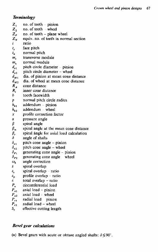
Crown wheel and pinion designs 67
Terminology no. of teeth - pinion no. of teeth - wheel no. of teeth - plane wheel equiv. no. of teeth in normal section ratio face pitch normal pitch transverse module normal module pitch circle diameter - pinion pitch circle diameter - wheel dia. of pinion at mean cone distance dia. of wheel at mean cone distance cone distance inner cone distance tooth facewidth normal pitch circle radius addendum - pinion addendum - wheel profile correction factor pressure angle spiral angle spiral angle at the mean cone distance spiral angle for axial load calculation angle of shafts pitch cone angle - pinion pitch cone angle - wheel generating cone angle - pinion generating cone angle - wheel angle correction spiral overlap spiral overlap - ratio profile overlap - ratio total overlap - ratio circumferential load axial load - pinion axial load - wheel radial load - pinion radial load - wheel effective cutting length
Bevel gear calculations
(a) Bevel gears with acute or obtuse angled shafts: S,(90°.

68 Manual Gearbox Design
(b) Bevel gears with shafts at right angles: 6=90" When calculating the plane wheel, the pitch circle diameter of the crown wheel
and the ratio of the drive are generally taken as the basic data. In place of the ratio, the numbers of teeth, 2, and Z,, are assumed. The two numbers of teeth should not have a common factor unless this is absolutely unavoidable, and 2, should not be less than 8 except where used in automotive drives.
The pitch cone angle - wheel, 6,, For gears with shafts at an acute angle:
+cot6 Z
Z, sin 6 cot a,, =A
For gears with shafts at an obtuse angle:
-cot (180" - 6) z, cot 6,, = 2, sin (180" - 6)
For gears with shafts at 90" angle:
The generating cone angle - wheel, a,, The generating cone angle results from the pitch cone angle through the angle correction and can be calculated as follows:
6P2 = + O k (4)
The generating cone angle, B P 2 , and the angle correction, wk, for the most common number of teeth ratios and at a pitch cone angle of 90" are listed in Table 5.1. Calculation of the pitch cone angle, Bo,, for the tooth ratios listed can be obtained using the values 6,, and wk as follows:
= 6 P 2 -wk ( 4 4 For all ratios at 90" shaft angles or with the shafts at acute or obtuse angles, the
The angle of correction is calculated as follows: pitch cone angle, do,, can be calculated as shown above.
w k = 6 P 2 - 6 0 2 (4b)
The generating cone angle - pinion, 6,, The generating cone angle - pinion, a,,, for gears with shafts at acute or obtuse angles, is calculated as follows:
( 5 ) 6,, = 6 - 6,,
For pinions with shafts at right angles:
6,, = 90" - 6 p 2

Crown wheel and pinion designs 69
Table 5.1 wk, a,,, Z , and u, depending on Z , and Z , : for Z , = 6 to 17 and Z , = 18 to 39
20
21
22
23
24
25
26
27
28
29
Angle correction, wk = Cone angle, 6,, = No. of teeth - plane wheel, Z,= Calculation factor, u =
- 5 6 5 1' - 72"30 70'0 - 22.019 1 22.347 8 - 0.524 263 0.532090
l"15' l " 9 57' 76"o 73"30 71"O 22.6734 22.9449 23.267 6 0.515 305 0.521 474 0.528810
l"37' l"26 l"11' 77"O 74"30 72"O 23.6050 23.868 1 24.183 5 0.513 152 0.518871 0.525729
1'32' l"16 5 6 77"30 75"O 72'30 24.5826 24.8645 25.1646 0.512 138 0.517636 0.524263
1'30 1 O 9 l"15' 78"O 75"30 73"30 25.558 5 25.822 5 26.073 7 0.51 1 169 0.516449 0.521 474
l"30 1'34' 1"6 78"30 76'30 74"O 26.532 8 26.735 8 27.047 9 0.510246 0.514206 0.520 151
1'32' l"32' l"30 79"O 77"O 75"O 27.505 3 27.7102 27.9523 0.509357 0.513 152 0.517636
1'36 1'32' l"27' 79"30 77"30 75"30 28.4770 28.6797 28.921 1 0.508518 0.512138 0.516449
l"41' l"34' l"25' 80"O 78"O 76"O 29.447 3 29.647 8 29.887 7 0.507712 0.511 169 0.515305
42' 67'30' 22.730 2 0.541 196
45' 68'30 23.645 3 0.537 392
52' 69"3O 24.555 1 0.533 806
l"3' 70"30 25.4604 0.530425
48' 71"O 26.440 5 0.528 8 10
l " 6 72"o 27.337 9 0.525 729
56' 72"30 28.3102 0.524 263
l"19' 73"30 29.202 5 0.521 474
l"14' 74"O 30.168 8 0.520 15 1
34' 64'0 22.252 1 0.556 303
28' 65'0' 23.170 9 0.55 1 688
27' 66"O 24.08 1 9 0.547 3 15
3 0 67'0 24.986 4 0.543 183
37' 68'0 25.855 0 0.539 270
48' 69'0 26.778 7 0.535 573
l"2' 70"o 27.668 7 0.532090
4 9 70" 30 28.643 0 0.530425
l "9 71'30 29.525 9 0.527 248
l"2' 72" 30.492 3 0.525 729
1 9 61'30 22.757 8 0.565 945
3 9 63'0 23.568 6 0.561 161
34' 64"O 24.477 3 0.556 303
34' 65"O 25.377 7 0.551 688
37' 66'0 26.271 1 0.547315
45' 67'0 27.1592 0.543 183
5 6 68'0 28.042 0 0.539 270
4 0 68'30 29.0192 0.537 392
57' 69"30 29.893 1 0.533 806
4 6 70'0 30.861 2 0.532 090

70 Manual Gearbox Design
Table 5.1 (cont.)
.\.. 6 7 8 9 10 11
30 1'49 80'30 30.4 17 0 0.506 950
31 l"27' 80"3O 3 1.430 9 0.506950
32
33
34
35
36
l"37' 81'0 32.398 9 0.506 232
l"18' 81'0 33.411 3 0.506 232
1'30 81'30 34.377 5 0.505 551
l"14 8 l"3O 35.388 6 0.505 551
l"28' 82"O 36.353 7 0.504913
37 1'13' 82"O 37.363 8 0.504113
38 l"23' 82"30 38.315 1 0.504 81 7
39 1'15' 82"3O 39.336 7 0.504317
1'38 78"3O 30.6148 0.5 10 246
1'43' 79"O 31.580 1 0.509 357
l"50 79"3O 32.545 2 0.508518
l"29 79"3O 33.566 2 0.500518
1'38' 80"O 34.5244 0.507712
l"49' 8P3O 35.486 5 0.506 950
l"3O 80"3O 36.5004 0.506 960
l"43' 81"O 37.461 2 0.506232
l"26 81"O 38.473 6 0.506 242
l"41' 8 1'30 39.433 0 0.505 531
l"26 76'30 30.852 5 0.5 14 208
1'28' 77"O 31.8154 0.513 152
1'32' 77"3O 32.776 8 0.512 138
1'38' 78"O 33.737 2 0.511 169
l o w 78'30 34.696 7 0.5 10 246
1'51' 79"O 35.658 0 0.509 857
1'32' 79"O 36.673 7 0.509 857
l"42' 79"3O 37.6009 0.508 508
l"53' 80"O 38.534 1 0.509 7 1 2
l"36 80"O 39.601 5 0.507712
l"12' 74"3O 31.1323 0.51 8 871
lo l l ' 75"O 32.093 4 0.5 17 636
l"12' 75"3O 33.052 7 0.5 16 449
l"15' 76'0 34.010 1 0.5 15 305
l"2O 76'30 34.966 1 0.514208
1'25' 77"O 35.9206 0.513 152
l"32' 77"3O 36.873 9 0.512 180
1'40 78"O 37.826 5 0.51 1 169
l"49 78"3O 38.771 0 0.510766
l"30 78"3O 39.799 2 0.510 246
5 6 72"3O 31.455 8 0.524 263
l"23' 73"3O 32.331 4 0.521 474
l"21' 74"O 33.289 7 0.520 151
l"21' 74"3O 34.245 5 0.5 18 871
1'23' 75"O 35.199 3 0.5 17 636
l"27' 75"3O 36.151 4 0.51 6 449
l"31' 76"O 37.1020 0.51 5 805
1'37' 76"3O 38.181 4 0.514 242
l"45' 77"O 38.991 6 0.513 152
1'23' 77"O 40.025 9 0.513 152
1'8' 71"O 31.7286 0.528810
l"2' 71'30 32.689 4 0.527 248
5 8 72"O 33.646 7 0.525 729
5 6 72'30 34.601 4 0.524 263
5 6 73"O 35.553 7 0.522 848
57' 73"30 36.503 2 0.521 474
l "0 74"O 37.456 8 0.520 151
l"3' 74"30 38.246 5 0.518 871
1 O 9
75"O 39.2400 0.5 13 670
l"15' 75"30 40.283 0 0.516 449

Crown wheel and pinion designs 71
Table 5.1 (conr.)
18
19
20
21
22
23
24
25
26
27
w, =
a,, = Z , = U =
17' 58"O 22.404 3 0.589 588
28' 59"30 23.21 1 8 0.580 295
15' 6W30 24.1280 0.574475
37' 62"O 24.9165 0.566 283
33' 63"O 25.813 4 0.561 161
3 4 64"O 26.702 5 0.556 303
39' 65"O 27.5844 0.551 688
47' 66'0 28.6404 0.547 3 15
28' 66'30 29.441 9 0.545 221
2 0 54"30 22.109 8 0.614 160
23' 56"O 22.918 1 0.603 107
31' 57"30 23.7136 0.592 846
1 6 58'30 24.629 4 0.586 4 14
35' 60'0 25.403 3 0.577 347
29' 61'0 26.297 1 0.571 677
27' 62"O 27.181 6 0.566 283
28' 63'0 28.085 1 0.561 161
34' 64"O 28.927 8 0.556 303
43' 65"O 29.791 2 0.551 688
23' 52"30 22.688 6 0.630 239
23' 54"O 23.485 2 0.618 032
0 55"O 24.4156 0.610389
11' 56"30 25.1832 0.599 599
28' 58"O 25.941 9 0.589 588
2 0 59"O 26.832 5 0.583315
15' 60'0 27.7127 0.577 347
15' 61"O 28.583 9 0.571 677
18' 62"O 29.446 7 0.566 283
2 4 63"O 30.302 7 0.561 161
18' 50"30 23.327 5 0.647 987
17' 52"O 24.1 1 1 4 0.634 510
22' 53"30 24.879 9 0.621 999
2' 54"30 25.794 7 0.614 160
17' 56"O 26.534 7 0.603 107
7' 57"O 27.424 4 0.596 182
3 0 58'30 28.1479 0.586 414
28' 59"30 29.0149 0.580295
29' 6W30 29.872 7 0.574475
33' 61"30 30.723 0 0.568 945
8' 48"30 24.033 3 0.667 597
6' 50"O 24.802 9 0.652 707
1 0 51'30 25.555 5 0.638 888
18' 53"O 26.294 7 0.626 064
2' 54"O 27.1934 0.618 032
1 9 55"30 27.908 2 0.606 700
11' 56'30' 28.780 8 0.599 599
7' 57"30 29.642 3 0.592 846
6' 58"30 30.493 5 0.586 41 4
9 59"30 31.335 9 0.580295
- 8' 46'30 24.814 9 0.689 303
-11' 48'0 25.567 2 0.672 821
- 8' 49"30 26.301 6 0.657 540
- 1' 51"O 27.021 8 0.643 376
12' 52'30 27.730 5 0.630 239
- 2 53"30 28.6120 0.621 999
19' 55"O 29.298 7 0.610389
13' 56'0 30.1554 0.603 107
11' 57"O 31.001 5 0.596 182
12 58'0 31 337 8 0.589 580

72 Manual Gearbox Design
Table 5.1 (cont.)
2, \.' 12 13 14 15 16 17
28
29
30
31
32
33
34
35
36
37
42' 67'30 30.307 0 0.541 196
59' 68'30 31.168 7 0.537 392
48' 69'0 32.134 4 0.535 573
40' 69'30 33.096 0 0.533 806
1"Y 70'30 33.947 2 0.530425
5 9 71"O 34.901 5 0.522 8 10
5 6 71"30 35.8529 0.527 248
55' 72"O 36.801 0 0.525 729
56' 72'30 37.7469 0.524 263
58' 73"O 38.6908 0.522 848
2 4 65"30 30.770 6 0.549 475
39' 66'30 31.6228 0.545 221
56 67'30 32.471 8 0.541 196
45' 68'0 33.434 7 0.539 270
37' 68"30 34.393 1 0.537 392
l " 0 69'30 35.23 1 2 0.533 806
55' 70"o 36.182 1 0.532 090
53' 70"30' 37.1298 0.530425
51' 71 "0 38.074 3 0.528810
52' 71"30 39.061 4 0.527 248
3 4 w0 31.1530 0.556 303
4 6 65"O 31.9979 0.55 1 688
31' 65'30 32.968 5 0.549 475
48' 66"30 33.803 7 0.545 221
38' 67"O 34.763 7 0.543 183
2 9 67"30 35.7189 0.541 196
53' 68'30 36.542 7 0.537 392
48' 69"O 37.490 1 0.535 573
43' 69"3O 38.4340 0.533 806
43' 70'0 39.374 7 0.532090
41' 62"30 31.5668 0.563 692
21' 63"O 32.547 3 0.561 161
34' 64'0 33.378 2 0.556 303
1 9 64'30 34.345 6 0.553 961
37' 65'30 35.1 66 4 0.549475
27' 66"O 36.122 8 0.547315
4 8 67"O 36.936 4 0.543 183
42' 67'30 37.883 7 0.541 196
37' 68"O 38.8274 0.539 270
34 68"30 39.7670 0.537 392
15' 6W30 32.170 6 0.574475
23' 6 1'30 32.998 8 0.568 945
3 4 62"30 33.821 5 0.563 692
18' 63"O 34.792 0 0.561 161
34 w0 35.603 4 0.556 303
22' 64"30 36.561 4 0.553 961
42' 65'30 37.364 3 0.549 475
34 66"O 38.312 1 0.547 31 5
28' 66'30 39.255 9 0.545 221
53' 67"30 40.048 5 0.541 196
1 6 59"O 32.665 6 0.583 315
23' 6W0 33.486 1 0.577 347
32' 61'0 34.300 6 0.571 677
1 4 61"30 35.247 6 0.568 945
29' 62'30 36.076 3 0.563 692
45' 63'30 36.8744 0.558 703
34 64"O 37.828 6 0.556 303
24 64"30 38.777 3 0.553 961
47' 65'30 39.566 2 0.549 475
41' 66"O 40.501 3 0.547 315

Crown wheel and pinion designs 73
Table 5.1 (cont.)
z, 2 2 12 13 14 15 16 17
38 l"2' 73"30 39.6320 0.521 414
39 l " 6 74"O 40.571 8 0.520 151
53' 72"O 39.955 4 0.525 729
56 72"30 40.892 5 0.524 263
43' 70"30 40.312 3 0.530425
45' 71'0 41.2472 0.528 810
l"2' 69"3O 40.569 3 0.533 806
l"2' 7w0 41.503 0 0.532090
50 68'0 40.984 5 0.539 270
48' 68'30 41.916 6 0.537 392
36 66'30 41.436 8 0.545 221
33' 67"O 42.368 3 0.543 183
The pitch cone angle - pinion, Sol The pitch cone angle - pinion, Sol, is calculated from the generating cone angle using the following equation:
801 =a,, +% (7)
The sizes of the plane wheel should be calculated roughly with a slide rule or calculator initially, if they cannot be taken under u and Z, for gears with shafts a t right angle (see Table 5.1).
The cone distance, R , The cone distance, R,, is calculated from the following formulae:
R,=- do, 2 sin S,,
=dOz X U
where
1 2 sin S,,
u=-
Number of teeth - plane wheel, Z, The number of teeth - plane wheel, Z,, is calculated from the following formula:
Z,=-- z2 - 2 z , x u sin S,,
Tooth facewidth, b The tooth facewidth, b, is usually fixed by the designer, being relative to the gear tooth loading and allowable stress, but the following empirical values, given in relation to the cone distance, R,, provides a means of checking whether the tooth facewidth is suitable for the pressure angle chosen.

74 Manual Gearbox Design
Light and medium heavy-duty gears for machines and automotive duties:
pressure angle, 179 or 20"
tooth facewidth, b= R A
3.5 to 5.0
Heavy-duty gears for machines and automotive applications where the gear ratio, i , is less than 2.5-1 :
pressure angle, 20"
R A tooth facewidth, b = 3.5 to 5.0
Medium heavy-duty gears:
pressure angle, 20"
(13) R A tooth facewidth, b = - 3.5
Heavy-duty gears for machines, road and rail vehicles, where the gear ratio, i, is greater than 2.5-1 :
pressure angle, 22;"
R A tooth facewidth, b= 3.1 to 3.3
For very light duty, gears with facewidths, b, smaller than RA/5.0 may be used if the number of teeth Z , and Z , still allow sufficient profile overlap (see page 88).
Normal module, m, The normal module, m,, is determined in relation to the tooth facewidth, b.
The normal module should be between
b b - and - 7 10
Only in exceptional cases should this range for the normal module be slightly exceeded in either direction.
Hardened heavy-duty gears:
The following values are recommended for the best results:
b b mn=- to -
7 8
Heat-treated and soft gears:
b b mn=- to -
8 10
The preliminary determined value should be replaced with a normal module selected from Table 5.2, using the nearest to the calculated value.

Crown wheel and pinion designs 75
Table 5.2
1 1.25* 1 .so 1.75* 2 2.25* 2.50 2.75* 3 3.25* 3.50 3.75* 4 4.25* 4.50 -
5 - 5.5 - 6 - 6.50* -
7 - - - - 8 - 7.5
Modules marked with an asterisk should not be used if possible. Where they are used, the Klingelnberg Co. must be contacted before the design is completed.
Normal pitch circle radius, p The normal pitch circle radius is calculated using the following formulae:
or
Inner cone distance, Ri The inner cone distance should be calculated as follows:
Ri = R, - b
Checking the position of the gear hob at the plane wheel
The plane wheel is determined by the normal pitch circle radius, p , the normal module, m,, the cone distance, R,, and the inner cone distance, Ri.
The pitch cone generating line of the hob must be tangential to the circle with the radius:
P-m,
and its vertex must coincide with the contact point A. Since the cone angle of the hob is 60°, any pitch circle diameter, d, of the hob is
equal to its appertaining generating line. The layout of the plane wheel (Figure 5.1) is acceptable if the following conditions
are agreed:
1 The circle with the radius, Ri, must intersect the pitch cone generating line of the hob, AE, within the cutting length, S,, i.e. the intersection point, C (point where Ri intersects the pitch cone generating line) must be behind point B when viewed from point A, point B being the point where the cutting length S , commences. Only if this condition is met will the hob cut through at the inside diameter of the bevel gear. The most favourable condition is if point C is close to or at point B. With this condition fulfilled, wheels with spiral angles and small longitudinal forces can be obtained. 2 The circle with the radius, R,, must also intersect the pitch cone generating line

76 Manual Gearbox Design
Figure 5.1
of the hob, AE, within the cutting length, S,. i.e. the intersection point D (the point where R, intersects the pitch cone generating line) must be before point E when viewed from point A. Point E is the point where the cutting length S, ends, and only when this condition is met will the hob cut through at the outside diameter of the bevel gear.
A check can be carried out quickly and simply using Figure 5.2(a) in conjunction with either Figure 5.2(b) or 5.2(c), respectively. Figure 5.2(a) produces a number of part circles with the radii p - m , , Ri and R,. Figure 5.2(b) contains diagrams of the pitch cone generating lines of the gear hobs of the series A, B and C which are at present in use, whereas Figure 5.2(c) gives similar data for gear hobs of the previous series a, b and c which are still in use.
The following data are given in Figures 5.2(b) and 5.2(c):
(a) d,=smallest pitch circle diameter of hob (see Figure 5.1) (b) S,=effective cutting length
A transparent copy of either Figure 5.2(a) or 5.2(c), whichever is relevant, should be placed on Figure 5.2(a) in such a way that the horizontal line m, on either Figure 5.2(b) or 5.2(c) coincides with the line p-rn , on Figure 5.2(a). The vertical lines on the right-hand side on the m, and p - m, values, in both the transparency and Figure 5.2(a), must also coincide. The position of the gear hob on the plane wheel can now easily be plotted as in Figure 5.1.
Then the intersecting points of the Ri and R , circles in Figure 5.2(a) with the horizontal m, line (the pitch cone generating line) of Figure 5.2(b) or 5.2(c), whichever is being used, must be determined and checked to find if the required cutting length S, is well within the effective cutting length S,, whereby extra consideration should be given to check that Ri is laid out as specified in condition 1
Layout of the plane wheel
(page 75).

Crown wheel and pinion designs I1
Figure 5.2(a) Graph forchecking the position of the gear hob - see also Figures 5.2(b) and 5.2(c). If the positions of gear hobs are to be checked which have a cone distance R , not given in the graph above, then the positions must be found by drawing them out on millimetre graph paper (Figures 5.2(a), (b) and (c) should be enlarged to 200% their present size for accurate measurement in mm)
If the check shows that condition 1 is not fulfilled, i.e. the circle with Ri does not intersect the pitch cone generating line within the cutting length, S,, then the number of teeth, 2, and Z, , or the normal module, must be reduced. Also where the design permits, increasing the pitch circle diameter of the gear, de,, will also help solve this problem.
Further, if condition 2 (page 75) is not complied with, i.e. the circle with R , does not intersect the pitch cone generating line of the hob within the cutting length, S,, then either the number of teeth, Z , and Z , , or the normal module, must be increased.
After the layout of the drive has been determined, the values for R,, Ri, p and Z, , which have so far only been calculated roughly, should now be recalculated accurately. R,, Ri and p should be calculated to an accuracy of 0.01 mm and Z , should be calculated to an accuracy of O.OO0 1 mm.

78 Manual Gearbox Design
Figure 5.2 (b) Graph for checking the position of the gear hob - see also Figures 5.2(a) and 5.2(c)
Notes: 1 The grid above is to be placed onto Figure 5.2(a) in such a way that the horizontal line m, on the grid, which represents the selected normal module, coincides with the horizontal line in Figure 5.2(a), which represents the approximate value of p-m, . The vertical line at the right-hand side of the m, values on the grid, and the vertical line at the right-hand side of the p-m,, values in Figure 5.2(a), must also coincide
2 Mark the points on the horizontal rn, line where the line is intersected by the circles which represent the approximate Ri and R , values
3 Then check whether the required cutting length S, is well within the effective cutting length S , of one of the gear hobs of series A, B or C
Having calculated these values, the rest of the values required can now be calculated using the formulae given in the following pages.
Transverse module, m, The transverse module is calculated as follows, to an accuracy of O.OO0 1 mm:
PCD dia. - wheel No. of teeth - wheel m, =
(20) -_ do2 - 2 2

Crown wheel and pinion designs 79
Figure 5.2(c) Graph for checking the position of the gear hob - see also Figures 5.2(a) and 5.2(b)
Notes: 1 The grid above is to be placed onto Figure 5.2(a) in such a way that the horizontal line m, on the grid, which represents the selected normal module, coincides with the horizontal line in Figure 5.2(a), which represents the approximate value of p-m.. The vertical line at the right-hand side of the m, values on the grid, and the vertical line at the right-hand side of the p-mn values in Figure 5.2(a), must also coincide
2 Mark the points on the horizontal m, line where the line is intersected by the circles which represent the approximate Ri and R , values
3 Then check whether the required cutting length S, is well within the effective cutting length S, of one of the gear hobs of series a, b or c
4 Series b has two sizes, b, and b,, which differ by the small diameter do
Pitch circle diameter - pinion, do, The pitch circle diameter - pinion is calculated as follows, to an accuracy of 0.01 mm:
d o , =No. of teeth - pinion x Transverse module = Z , x m, (21)
Pressure angle, u Selection of a suitable pressure angle is governed by the purpose for which the gears are intended and the gear ratio:

80 Manual Gearbox Design
(a) for general engineering purposes and gears for motor cycles and tractors, a
(b) for gears for automotives with big ratios, a pressure angle, a, of 179 is usually
(c) for heavy-duty gears for automotives and general engineering purposes with
pressure angle, a, of 20" is usually used
selected
ratios less than 2.5 : 1, a pressure angle, a, of 2 2 9 is usually chosen
Profile correction
In a tooth system using profile-corrected teeth, the pitch centre-line of the basic rack teeth is moved a certain amount from the pitch circle - pitch cone of the mating gear.
The amount by which the centre-line of the rack is moved away from the pitch circle - pitch cone is expressed in fractions of the normal module, m,, and is known as the profile correction factor, x.
The profile correction is positive if the centre-line of the basic rack lies outside the pitch cone, V-plus wheel; it is negative if the centre-line lies within the pitch cone, V-minus wheel.
If a profile correction is considered, and especially if it is for heavy-duty bevel gears, a careful investigation of the profile should be carried out. For further information see the section 'Rules for the examination of tooth profile by the graphic method' (page 100).
'0'-bevel gears
0 gears
0 gears are gears where the mating wheels have not been profile corrected, i.e. the profile correction factor, x, is zero.
The addendum of such gears is as follows:
Addendum - pinion, hk, =Normal module, m,
Addendum - wheel, h k z =Normal module, m, (22)
(23)
V - 0 gears
A drive is a V-0 drive if it has profile-corrected teeth with the same amount of correction in the pinion and crown wheel, but in opposite directions from the centre-line. The profile correction of the pinion is positive (V-plus wheel), and the sum of the profile correction factors is therefore x,+x, =O.
This type of gear is very popular, especially for big ratios, as it is possible to make the pinion teeth stronger at the expense of reducing the strength of the crown wheel teeth, thus balancing the strength of the smaller pinion and the larger crown wheel.
For calculation of the addendum for bevel gears which are classified V - 0 gears, use the following formulae:
Addendum - pinion, h,, = ( I +x,) Normal module = ( I + x , ) m,

Crown wheel and pinion designs 81
Z y ' 6 7 8 9 10 11 12 13 14 15 16
22 24 26 28 30 35 40 45 50 55 60 70 80
1.46 1.46 1.43 1.42 1.42 1.40 1.40 1.40 1.39 1.36 1.40 1.40 1.38 1.36 1.41 1.41 1.38 1.35 1.32 1.42 1.42 1.39 1.37 1.33 1.29 1.23 1.43 1.43 1.40 1.38 1.34 1.29 1.24 1.18 1.12 1.44 1.44 1.42 1.39 1.35 1.30 1.24 1.18 1.12 1.06 1.00 1.45 1.45 1.43 1.41 1.36 1.31 1.25 1.18 1.12 1.06 1.00 1.47 1.47 1.45 1.42 1.38 1.32 1.25 1.18 1.12 1.06 1.00 1.48 1.48 1.46 1.44 1.39 1.33 1.26 1.18 1.13 1.06 1.00 1.50 1.50 1.49 1.47 1.41 1.34 1.27 1.19 1.13 1.07 1.00 1.52 1.52 1.51 1.48 1.44 1.36 1.28 1.20 1.13 1.07 1.00
Table 5.4 Pressure angle a = 20°, 2, I, i > 1
6 7 8 9 10 11 12 13 14 15 16
18 20 22 24 26 28 30 35 40 45 50 55 60 70 80
1 .OO 1.17 1.02 1.00 1.00
1.30 1.30 1.27 1.23 1.16 1.04 1.00 1.00 1.28 1.28 1.26 1.22 1.16 1.06 1.00 1.00 1.26 1.26 1.25 1.22 1.16 1.07 1.00 1.00 1.26 1.26 1.25 1.22 1.17 1.08 1.00 1.00 1.26 1.26 1.25 1.22 1.17 1.09 1.00 1.00 1.27 1.27 1.26 1.23 1.18 1.11 1.00 1.00 1.28 1.28 1.28 1.24 1.20 1.13 1.02 1.00 1.29 1.29 1.29 1.25 1.21 1.15 1.05 1.00 1.31 1.31 1.30 1.26 1.23 1.16 1.07 1.00 1.32 1.32 1.32 1.29 1.24 1.18 1.09 1.00 1.33 1.33 1.33 1.30 1.26 1.20 1.11 1.03 1.36 1.36 1.36 1.32 1.29 1.24 1.16 1.08 1.39 1.39 1.38 1.35 1.32 1.27 1.20 1.12
1.00 1.00 1.00 1.00 1.00 1.00 1.00 1.00 1.00 1.00 1.00 1.00 1.00 1.00 1.00 1.00 1.00 1.00 1.00 1.00 1.00 1.00 1.00 1.00 1.00 1.00 1.00 1.00 1.00 1.00 1.00 1.00 1.00 1.00 1.00 1.00 1.00 1.00 1.00 1.00 1.00 1.00 1.01 1.00 1.00
Addendum - wheel, h,, = 2 x Normal module - addendum - pinion = 2 x m,- h,, (25 )
The value 1 + x1 depends upon the number of teeth ratio and the pressure angle, a, and can be found from Tables 5.3-5.5. The profile correction factor, x, in these tables has been selected with a view to avoiding undercutting the pinion teeth flanks.

82 Manual Gearbox Design
Table 5 5 Pressure angle a = 229, Z , I , i 5 3
2 ' 6 7 8 9 10 11 12 13 14 15 16
18 20 22 24 26 28 30 35 40 45 50
1.00 1.00 1.00 1.18 1.12 1.03 1.00 1.00 1.00
1.12 1.03 1.00 1.00 1.00 1.04 1.00 1.00 1.00 1.04 1.00 1.00 1.00
1.00 1.00 1.00 1.00 1.00
1 .00
1.00 1.00 1.00 1.00 1.00 1.00 1.00 1.00 1.00 1.00 1.00 1.00 1.00 1.00 1.00 1.00 1.00 1.00
1 .00
1.00 1.00 1.00 1.00 1.00 1.00 1.00 1.00 1.00 1.00 1.00 1.00 1.00 1.00 1.00 1.00 1.00 1.00 1.00 1.00
1 .OO
Note: For heavy-duty gears with pressure angles 172,20" or 222, having pinions with few teeth, special gear hobs with strengthened pinion teeth must be used
Factor 1 +XI for determination of the addendum
The addendum h,, or h,, is calculated using formulae (24) and (25), applicable to 6 = 90" and b = 7 to 10 m, only.
Bevel gear V drives
On V gears, the profile corrections of the pinion and wheel are not equal. The sum of the profile correction factor is, therefore,
x, +x, *o The profile corrections may be in the same direction or in opposite directions.
importance. There are both V-plus gears and V-minus gears, but only the V-plus gears are of
V plus gears
V-plus gears are gear pairs where the mating pinion and wheel are either both V-plus gears or where one of the pair is a V-plus gear and the mating gear either an 0 gear or a V-minus wheel, provided that the sum of the profile correction factors is
x,+x, >o V-plus gears are usually employed where there are small ratios so as to obtain a
bigger effective pressure angle or a smoother running pair of gears.

Crown wheel and pinion designs 83
The addendum of V-plus gears is calculated as follows:
Addendum - pinion, h,, = ( I + x, )m,
Addendum - wheel, h,, = (1 + xJm,
(26)
(27)
V-plus gears differ from 0 gears and V-0 gears also in their outside diameters. For the calculation of the outside diameters of V-plus gears, see formulae (49)-(52) inclusive.
Tooth profiles
Klingelnberg make hobs for tooth profiles, numbers 1 4 (designated by Klingeln- berg Z, I, Z, 11, Z, 111 and Z, IV). They differ from one another in tooth thickness and the radii at the tips of the teeth.
If teeth are cut with no profile correction, then the following difference in each of the different profiles will be revealed:
Tooth profile 1, Z , I, will produce pinions and wheels with equal tooth thicknesses.
Tooth profile 2, Z , ZI, will produce pinions with teeth that are 0.05 x m thicker than the teeth produced by profile 1 (thickness measured at the pitch circle).
Tooth profile 3, Z , ZZI, will produce pinions with teeth that are 0.10 x m thicker than the teeth produced by profile 1 (thickness measured at the pitch circle).
Tooth pro& 4, Z , Z V , will produce pinions with teeth that are 0.15 x m thicker than the teeth produced by profile 1 (thickness measured at the pitch circle).
The tooth thicknesses of the hobs for tooth profiles 2,3 and 4 are reduced at the pitch circle by the relevant amount to suit the increased thicknesses given, and thus are smaller than
t 7z - = m n .- (pinion hobs) 2 2
The tooth thicknesses of the hobs for the crown wheel are bigger than
t n - = m, - (wheel hobs) 2 2
The tooth profiles 1 and 3 are the ones most favoured for general use (see below).
Tooth profile 1, Zf I
Tooth profile 1, used with pressure angles, a, of either 20" or 22?, is used for general engineering gears and in the automobile industry for lorries with gears having ratios that are less than 2.5-3 : 1 .
The gear hobs for tooth profile 1 can be used for cutting both the pinion and crown wheel.

84 Manual Gearbox Design
Tooth profile 3, 2,111
Tooth profile 3, used with a pressure angle, a, of 17:", is used for automobile industry gears for (a) cars, and (b) lorries where the gear ratio is bigger than 2.5-3 : 1.
On gears having tooth profile 3, the teeth of the pinion are made thicker by reducing the thickness of the teeth of the crown wheel. This compensates for the heavier loads on the pinion teeth due to the small number of teeth.
The pinion hobs for tooth profile 3 have right-hand spirals, which are the most common in the automobile industry. Should the need arise for a left-hand spiral, this must be particularly specified when ordering, because left-hand hobs are not normally kept in stock.
Besides tooth profiles 1 (2, I) and 3 (2, 111), tooth profiles 2 (Zf 1I)and 4 (2, IV) may be employed in special cases where an even better compensation of the differing loads of the pinion and crown wheel is necessary - tooth profile factor Y, Lewis formulae. Before calling up these special gear hobs, contact should be made with the Klingelnberg works.
Gear blank dimensions

Crown wheel and pinion designs 85
w1 = H , - (c , + a , + (x + x,)m, (49) x sin 6,,
w2 = H 2 - (c2 + a,) + (xl + x,)m, (51)
x sin 6,,
a, = b cos 6,, (32) a, = b sin 6,, (33) k ,=hk2 COS S,, k , = h,, sin 6,, (35)
d o , w , = - - (c, + a , ) + (x , + x2)mn (50) 2 x sin a,,
2 d o 1
x cos a,, w, =-- (c, +a,)+ (x, +x, )m, (52)
c1 = h,, sin 6,, d k a l = d o l + 2 k l
(36) (37)
dki,=dkal-2bsinSP, (38) I d k i l = d k a l -2a2
d k a Z = + 2k2
dki2 = dka2 - 2b sin S,,
w l = H , - ( c l + a l )
w, = H , - (c, + a,)
d o , H,=-cot So, 2 (44)
Overlapping of tooth action
The duration of engagement of spiral bevel gears is determined by the spiral overlap, E,, and the profile overlap, E,. As a general rule, the spiral overlap, E,, should be more than 1.5, E,> 1.5, and the profile overlap, cp , should be more than 1, E,> 1.0. Experience has proven that with gear pairs where the pinion has a small number of teeth, the best results are obtained if the sum of E, and c p is not less than 2.5: therefore, the profile overlap, E, should be as large as possible.
Spiral overlap, E,
The spiral overlap, E,, is taken on the mean cone distance and is the ratio between S, and t , as illustrated in Figure 5.5. Hence,
(53) I , I
E, = s,/t = E, - E ,
where the values for E: and E,’ can be obtained from Figures 5.6(a) and 5.6(b).

86 Manual Gearbox Design
Figure 5 5
Figure 5.6 Spiral overlap and profile overlap:
(a) Spiral overlap, E:, for tooth width R , --p (b) Spiral overlap, E’:, for tooth width R i - p (c) Calculating factor, e, depending on the mean spiral angle,
&,,(e = sin’ tl + cos2 tl x cos’ &)

Crown wheel and pinion designs 87

88 Manual Gearbox Design
Profile overlap, E,
The profile overlap, cP, is the ratio between the length of the path of contact and the transverse base pitch which is determined on the mean cone distance. The profile overlap is calculated using the following formulae:
= &,.e (54)
(55)
where
e = sin’ o! +cos’ a cos’ p, and
P R , -0.5b cos p, =
For values of e see Figure 5.6(c), and for values of EP see Figure 5.7 (a-f).
for the pinion, Znl, and the pressure angle, a.
formula:
E; is dependent on the profile correction factor, x, the equivalent number of teeth
The equivalent number of teeth - pinion, Z, , , is calculated from the following
cos3 p, cos a,, ‘Nl= (57)
Where the addendum, hk, =mn (formula 22), the profile correction factor, x, is zero at the outside diameter, but due to the angle correction, ok, at the centre of the face it is
where
b hwkm = tan o k - 2 (59)
For an addendum, h,,, which is not equal tom,, the profile correction factor, x, at the centre of the facewidth is calculated as follows:
h k l + h o k m - m n X, =
m,
Formulae for the determination of the external forces
Circumferential load, P,, derived from engine torque
The circumferential load, PuM, is determined from the torque, M,, and the diameter of the pinion, dM1, at the mean cone distance and is calculated as follows:
716N
n1 M,=-

Crown wheel and pinion designs 89
Figure 5.7(a-f) Intermediate value, E;, for the determination of the profile overlap, E,,

90 Manual Gearbox Design
Fiepn S7 (cont.)

Crown wheel and pinion designs 91
Figure 5.7 (cont.)

92 Manual Gearbox Design
where
N = power to be transmitted (in horse-power) n, =no. of revolutions of pinion (rpm)
The torque of an internal combustion engine is determined by multiplying the maximum engine torque at the appropriate number of revolutions for the gear ratio by the gear ratio being considered, thus arriving at the torque output in that gear.
The circumferential load, PUM, is calculated using the following formula:
M,2000 p =- uM d M 1
where
dMl=dOl-bsin6,,
Circumferential load, PUR, derived from the friction torque
When calculating drives for automotives, the circumferential load, PUR, of the pinion should also be derived from the friction torque.
The formula used to calculate the friction torque is as follows:
where
(a) motorcycles and cars, p = 0.6 (b) lorries and tractors, p = 0 . 8 (c) caterpillar vehicles, p = 1 .O (d) rail vehicles - to Kniffler-Curtius:
p = friction coefficient, for applications as follows:
where Vh=speed in km/h
QH = weight on driving axle (kg) Z,,Z, = no. of teeth on bevel gears is , = gear ratio - spur or helical, between power source and tyres rw = effective tyre radius or track radius - m
Size and direction of the axial thrust, Pa
The size of the axial thrust of the driving wheel, Pal, and of the driven wheel, Po,, depends on the pitch cone angles do, and dO2, respectively, the pressure angle CL, and the spiral angle, p,. Considering the small difference between 6, and a,, the calculation may be made using 6,, and 6,, in place of dol and dO2.

Crown wheel and pinion designs 93
The spiral angle, p,, is calculated using the following formula:
P R , - 0.6b
cos p, =
The axial thrust of the smaller wheel - pinion is calculated as follows:
The axial thrust of the bigger gear wheel is calculated as follows:
Formulae (65b(67) apply for all gears and cover shafts at any angle, 6. If the hand of rotation and the spiral are the same, then plus (+) should be
inserted in the formula for the driving gear and minus (- ) in the formula for the driven gear.
Alternatively, if the hand of rotation and the spiral are in opposite directions, then minus ( - ) should be inserted in the formula for the driving gear and plus (+ ) in the formula for the driven gear.
Note: In these calculations, the direction of rotation and the hand of spiral are always determined by looking at the gearwheel from the apex of the cone.
Where the calculated result in the axial thrust formulae is positive (+ ), the direction of thrust is away from the apex ofthe cone, i.e. out of mesh, whereas if the result in the axial thrust formulae is negative (-), the direction of thrust is toward the apex of the cone, i.e. into mesh.
As a rule, the hand of the spiral of the smaller gear, driving pinion, should be such that the main direction of rotation and the hand of spiral are the same if seen from the cone centre. With a drive arranged in this manner, the bending forces at the crown wheel are the smallest. In a reversible drive, where a similar duty is performed in both directions, it is recommended that a pinion with a left-hand spiral be used.
Values for the axial thrust are shown in Figure 5.8(a-c).
Size and direction of the radial force, P,.
For gears with shafts at right angles, S=90°, the radial force is equal to the axial thrust of the mating gear:
Pr1 = P a 2 (68)
P r z = P a 1 (69) Where the shafts are at an acute or obtuse angle, the following formulae apply:
For the smaller gear - pinion:
tan c1 cos S,, k tan p, sin S , ,

94 Manual Gearbox Design
Figure 5.8(a-c) angles, applicable to all angles of the shafts
Axial thrust, fa, relative to P , for (a) 172, (b) 20" and (c) 225" pressure
Note: If the direction of rotation and the hand of spiral are the same, then the top portion of the curves apply to the driving gear and the bottom portion to the driven gear. If direction of rotation and hand of spiral are opposed, then the bottom portion of the curves apply to the driving gear and the top portion to the driven gear

Crown wheel and pinion designs 95
For the larger gear:
(71) ) P r 2 = P u (tan;o;;r6pz k tan f i r sin 6,,
Should the direction of rotation and the hand of spiral be the same, then minus ( - ) should be inserted in the formula for the driving gear and plus (+ ) in the formula for the driven gear.
However, if the hand of rotation and the spiral are in opposite directions, then plus ( + ) should be inserted in the formula for the driving gear and minus ( - ) in the formula for the driven gear.
Where the calculated result in the radial force formulae is positive (+), the direction of the radial force is towards the shaft, whereas if the result in the radial force formulae is negative (-), the direction of the radial force is away from the shaft.
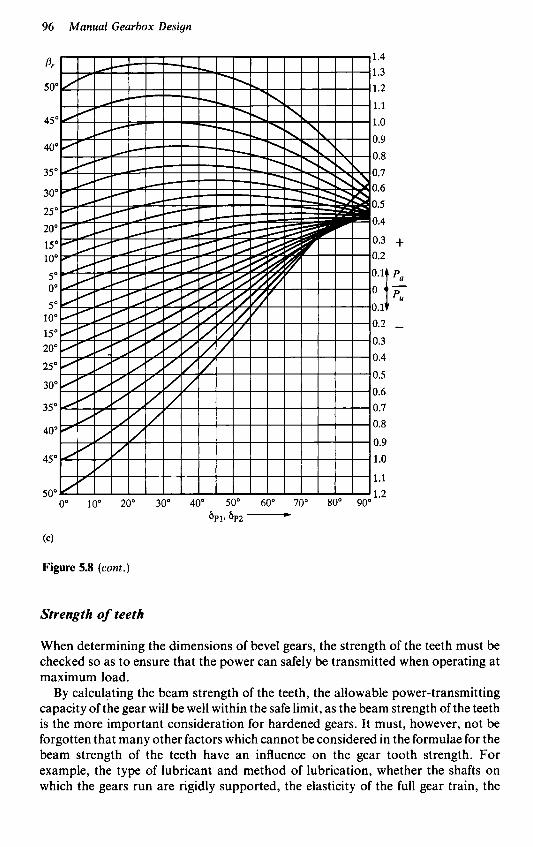
96 Manual Gearbox Design
(4
Figure 5.8 (coni.)
Strength of teeth
When determining the dimensions of bevel gears, the strength of the teeth must be checked so as to ensure that the power can safely be transmitted when operating at maximum load.
By calculating the beam strength of the teeth, the allowable power-transmitting capacity of the gear will be well within the safe limit, as the beam strength of the teeth is the more important consideration for hardened gears. It must, however, not be forgotten that many other factors which cannot be considered in the formulae for the beam strength of the teeth have an influence on the gear tooth strength. For example, the type of lubricant and method of lubrication, whether the shafts on which the gears run are rigidly supported, the elasticity of the full gear train, the

Crown wheel and pinion designs 91
tooth surface finish on both the face and flanks, together with the relative sliding motion between the mating faces - all have great influence upon the strength and ultimately the overall performance of the gear train.
The determination of the beam strength of the gear teeth using the Lewis formulae is calculated as follows:
P,,=a,6vm,.x.b.y 6
For bevel gears which run at higher speeds - above 33 ft/s - and which need a lot of attention to detail both in design and manufacture, the factor 6/6+ V can be replaced by 10/10 + V when calculating the dynamic load capacity of the gear drive, where the factors in the formula are as follows:
aB= static breaking strength (kg/cm2) - the static breaking strength for 16 MN.CR 5 , ECN 55 , is 12 OOO kg/cm2. The static breaking strength for other steels varies in proportion of their Brinell hardness to the Brinell hardness of 16 MN.CR 5 , Le. the Brinell hardness of 16 MN.CR 5 equals 200-235
=speed factor
10+ v
V=circumferential speed at the mean cone length, derived from the following formula:
d,, x n x n , 60 OOO m/s V= (73)
m, = normal module b = facewidth y = tooth profile factor, depending upon the equivalent number of teeth
Znl, the tooth profile, the pressure angle a and the rounding r at the gear hob, and for wheels with profile correction factor x, to formula
Note: When using hobs with big roundings (r=0.31 to 0.38mn), the value y for (60).
wheels without profile correction can be obtained from Table 5.6.
y Values for gears without profile correction (rounding at gear hob, r=0.31 to 0.38m,) (see Table 5.6)
They values for gears with profile-corrected teeth cut with hobs with big roundings, i.e. r=0.31 to 0.38m,, can be taken from Figures 5.9(a) and 5.9(b).

98 Manual Gearbox Design
Table 5.6
17t” u = 20” u = 222 ZN Tooth profile 3 Tooth profile 1 Tooth profile 1
10 11 12 13 14 15 16 18 20 22 24 26 30 35 40
0.068 0.074 0.079 0.082 0.086 0.090 0.093 0.098 0.103 0.107 0.110 0.113 0.118 0.122 0.126
0.068 0.074 0.078 0.082 0.086 0.090 0.093 0.098 0.102 0.106 0.109 0.112 0.117 0.121 0.125
0.071 0.078 0.082 0.087 0.09 1 0.095 0.098 0.104 0.109 0.113 0.117 0.120 0.125 0.130 0.133
There are also hobs with smaller roundings in use, and the y values for these roundings must be derived from a drawing of the tooth profile (see under ‘Rules for the examination of the tooth profile by the graphic method’, page 100).
The breaking safety formula is calculated using the following values:
(a) P,,, the tooth beam strength (b) PUM, the calculated torque - this torque is calculated as given in formula (61);
for general engineering and vehicle gears, vehicle gears must also be checked using the friction torque calculated as in formula (64)
The breaking safety formula is as follows:
(74) ‘bB Breaking safety, S, = - P ” M
The following safety values should be used with the breaking safety calculations:
(a) light lorries with Cardan shaft, 1st speed, 1.1-1.3 (b) block gear units without Cardan shaft, 1st speed, 1.6-1.8 (c) agricultural tractors, 1st and 2nd speeds, 2.5-4.0 (d) caterpillar vehicles, 1st speed, 3.0-4.0 (e) stationary gear sets, 3.0-5.0
value. The empirical safety values should always be compared with the higher safety

Crown wheel and pinion designs 99
Figure 5.9(a,b) Tooth profile factor, y (to be inserted into the Lewis formula) for increased cutter roundings
Note: For explanation of Z, I and Z , 111, see page 83

100 Manual Gearbox Design
(b)
Figure 5.9 (cont.)
Rules for the examination of the tooth profile by the graphic method
For bevel gears which are generated using Klingelnberg hobs, type No. KN3024, delivered after January 1953, the tooth profile factors y for the most common hobs may be taken from Figures 5.9(a) and 5.9(b). The tooth profile factors depend on Z , (the equivalent number of teeth in the normal section), calculated as shown in formula (57) and the profile correction factor x (see page 80). In Figure 5.9(a) and

Crown wheel and pinion designs 101
5.9(b), the limits for undercut and tooth thickness, like zero at addendum circle, are given.
Figures 5.lO(a) and 5.10(b) give the tooth base thickness factor,f= Sfm,,, which is also dependent upon Z , and x.
Figure 5.10(a,b) thickness at the root dircle
Notes: 1 For explanation of Z , I and Z , 111, see page 83 2 Addendum h,, and h,, to be determined according to formulae (22)-(27)
Profile correction factor, x, for determining the addendum and tooth
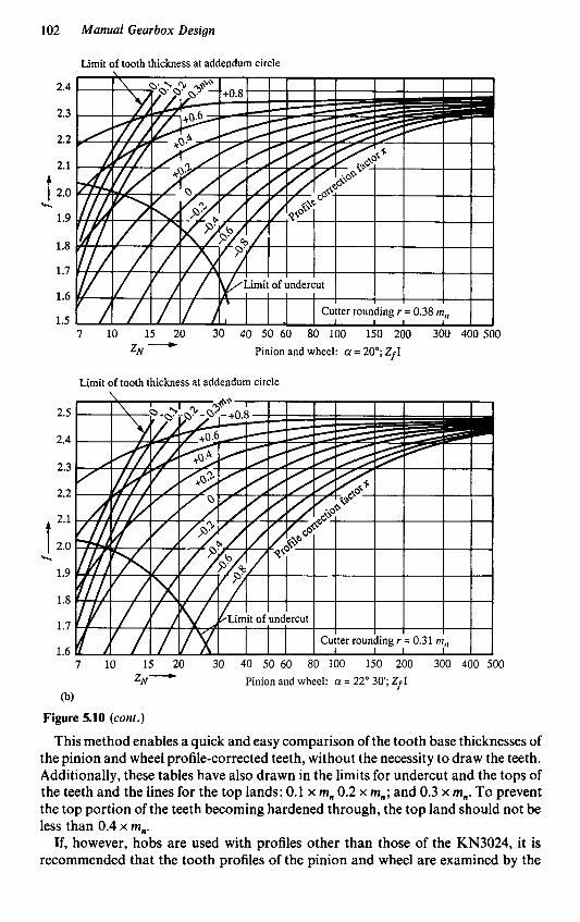
102 Manual Gearbox Design
Figure 5.10 (cont.)
This method enables a quick and easy comparison of the tooth base thicknesses of the pinion and wheel profile-corrected teeth, without the necessity to draw the teeth. Additionally, these tables have also drawn in the limits for undercut and the tops of the teeth and the lines for the top lands: 0.1 x m, 0.2 x m,; and 0.3 x m,. To prevent the top portion of the teeth becoming hardened through, the top land should not be less than 0.4 x m,.
If, however, hobs are used with profiles other than those of the KN3024, it is recommended that the tooth profiles of the pinion and wheel are examined by the

Crown wheel and pinion designs 103
graphic method, especially if the bevel gears are for heavy-duty service or if the ratio of the pinion and wheel is a big one. In the graphic method for this type of ratio, the tooth base thickness, S,, can be seen and thus the tooth profile factor, y, can be determined.
Examination of the tooth profile by the graphic method is also recommended where the breaking strength of gears of differing designs, but of similar overall dimensions and for the same duty, are to be compared.
Such examination should be carried out at the normal cross-section and at the centre of the tooth, i.e. at a distance R = RA-0.5b from the plane wheel centre, which enables the carrying out of the strength calculation to be completed and the overlap to be checked.
If it is also thought necessary that the undercut and the top land be checked, an examination at the normal cross-section of the pinion should be carried out at a distance R = R, - b from the plane wheel centre.
The examination of the undercut is only required for the pinion, since gear pairs with big ratios mean that the crown wheel can be regarded as a rack.
The following formulae apply for normal cross-sections at the small pinion diameter, if the appropriate value for R (distance of the point under consideration from the centre of the plane wheel) is inserted into the formula.
The spiral angle at the point under consideration is then
b=*- Y
cos*=- P - m n R
“‘n tan Y = - R sin II/
(75)
(77)
The equivalent number of teeth Z,, can be sufficiently accuratt-j calculateL using formula (57):
Zl z - N1 -cos3 COS do,
When using the above formula, the cosine of the uncorrected pitch cone angle a,,
The following data should also be calculated: is to be inserted.
Pitch circle dia., doni, at the normal cross-section:
d o n 1 = Z , 1 .mn
Base circle dia., dgnl, at the normal cross-section:
dgnl=donlcosa (79)
Profile correction due to the angle correction (ok according to Table 5.1, page 69):
(80) h,, = tan q ( R , - R)

179 Zr 111
U Pinion Wheel
7l II I --0.1 2
-+0.1 2
P 0.075 0.125 4 0.942 0.942 r 0.35 0.35
Zr I
20" 229
7l 7l - - 2 2
0.05 0.05 0.910 0.985 0.38 0.3 1

Crown wheel and pinion designs 105
Now the tooth profile can be laid out, and the involute curves between the addendum, dknl, and base circle, ggnl, can be generated in the known way through the terminal points of the normal thickness of tooth, S,, plotted on the pitch circle,
For laying out the shape of the bottom clearance, rounding the centre-line of the tooth must be drawn first. Then the tangent to the pitch circle should be drawn through the point where the centre-line of the tooth intersects the pitch circle, followed by a straight line parallel to the tangent of the pitch circle at a distance x x m, from the tangent toward the top of the tooth.
Now the centre of the top rounding radius, r, of the basic rack can be determined by plotting a point on the parallel line at a distance of t/2=n.mn/2. From the centre-line of the tooth and marking of the distances, p and q , as calculated from Table 5.7, this centre point describes a loop involute curve during the rolling movement with the top rounding radius of the basic rack. The equidistant to this loop involute curve can now be drawn, giving the bottom clearance rounding. If this curve undercuts the involute curve which has been drawn at the flank of the tooth, the tooth will be undercut.
Now tangents have to be drawn to the bottom clearance roundings at 30" to the centre-line of the tooth. The distance between the two points where the tangents contact the bottom clearance roundings is the tooth base thickness, S,, .
Now the line of influence of the tooth load should be drawn, i.e. a tangent to the base circle through point A at the top of the tooth. The distance, h, from the line, S,, (tooth base thickness), to the point where the tangent intersects the centre-line of the tooth, is the cantilever of the tooth load.
If S,, and h are scaled off the drawing - taking into account the scale to which the drawing is made - the tooth profile factor y can be calculated from the following formula:
do, 1
For the determination of the profile overlap, draw a vector from the point where the line of action intersects the pitch circle to the centre of the normal section and plot at the distance m,(l - x) a perpendicular line to the vector (the addendum line of the basic rack). The perpendicular line intersects the line of action at point I. The distance AI = E , is the path of contact of the normal section. The ratio between the path of contact, E,, and the pitch, ten, is the profile overlap E; of the normal section. For the calculation of the pitch, ten, the following formula applies:
ten = m,.n. cos c1 (86)
From E;, the pitch of the real section can be determined according to formula (54):
An example of a tooth profile layout calculation to the details given follows (the cp = E; x e. For the value of e see Figure 5.6(c), page 87.
emboldened numbers refer to previous formulae):
P - mnl
R 76 COS$= $=43"11'

106 Manual Gearbox Design
mn 77 tan Y = - R sin II/
75 / 3=$-Y -
78 donl = ZN1.m,
79 dgnl=donlcosa
80 h,, = tan m,(R, - R)
81 dknl +2(hk1 - k h o k )
82 d,,, =d,,, -4.6mn
h k l + h,k - mn 83 X= mn
w q=1+2xm, tan u
Y = 3"lO
b=40"1'
Z,, = 22.998
don, = 68.96
den, = 64.80
h,, = 0.32
dknl = 76.80
d,,, =63.00
x=0.31
- S, = 5.38
Example of spiral bevel gear design
Following is the method used to calculate the bevel gear drive for a machine tool drive:
shaft angle: 6 = 90" pinion speed: n, = lo00 rpm power transmitted = 15 hp drive ratio = 4 : 1
(to be maintained as accurately as possible)
large gear PC dia. = 180 mm tooth facewidth = 24 mm
Preliminary calculation of the plane wheel data (see Table 5.8)
Table 5.8
Formula Description. no. Formula Result
No. of teeth 2
Intermediate value 9
Z , 40 _-_ - z, 10
i = 4 to 1
u to Table 5.1, u=o.51 page 69

Crown wheel and pinion designs 107
Table 5.8 (cont.)
Formula Description no. Formula Result
Cone distance 8 R , =do2.u R,=92
Tooth width 11 R A b=19 to 26 b=- 3.5 to 5
mn=-
= 24 determined by design
Normal module 16 b m,=3 to 3.4 7 to 8 Use 3
Normal pitch 18a p=m,.Z,.u p=61.5 circle radius
Inner cone 19 R i = R , - b Ri = 68 distance
Checking position of the gear hob relative to the plane wheel
The calculated values R,, Ri, p and m, meet the requirements for the use of hob, m, = 3, since the effective length of cut S , of the hob is within the cutting length S , and value Ri is placed very favourably.
Table 5.9 gives the details of the formulae for the accurate calculation of the plane wheel data.
Accurate calculation of the plane wheel data (see Table 5.9)
Table 5.9
Formula Description no. Formula Result
Generating cone angle of crown wheel
Generating cone 6 angle of pinion
Intermediate value 9
Cone distance 8
No. of teeth, 10 plane wheel
6,, to Table 5.1, a,, = 77"30 page 69
6,, = 90" - a,, 6,, = 12'30
1 2 sin 6,,
u=- u=0.512 138
(Table 5.1, page 69)
R, =do,.u
Z,=2Z2.u Zp=40.971
R, = 92.1 8
(Table 5.1, page 69)

108 Manual Gearbox Design
Table 5.9 (coni.)
Formula Description no. Formula Result
Normal module
Normal pitch circle radius
Inner cone distance
Transverse module
Pitch circle diameter of pinion
Pressure angle
Intermediate value
Addendum of pinion: V - 0 gear
Addendum of crown wheel V - 0 gear
16
1 Sa p = m,.Z, .u
19 Ri=RA-b
d o ,
z2
m =- 20
21 dOl=Zl.m,
-
1 + X I
(see page 81)
24 h k l = ( l
25 h,, = 2m, - h,,
m,=3
p = 61.46
Ri = 68.18
ms=4.5
do, =45
a=20"
1 + X I = 1.2
h,, =3.6
hk2 = 2.4
Dimensions of the gear blanks for V - 0 gears (see Table 5.10)
Table 5.10
Formula no. Formula Result
28 29 31 33 35 36 37 39 40 42
46
48
a , = b cos S,, k , = h , , ~ 0 ~ 6 , , C, = h,, COS S,, a, = b sin S,, k, = h,, sin S,, c, = h,, sin S,, dknl =dol + 2 k l
d k i l =dkal -2a2
dkn2=do2 + 2k2
dki2 = dk02 - 2a I
do2 w, =--(c, + a , ) 2
do 1 w2 =-- (c2 +a,) 2
a , =23.43 k , -3.51 C, = 2.34 a,=5.19 k, =OS2 c I =0.78 d,, = 52.07 dki, =41.64 d,,, = 181.04 d,,,= 134.18
W , =65.79
W , = 14.97

Crown wheel and pinion designs 109
Overlap (see Table 5.1 1)
Table 5.1 1
Formula Description no. For m u 1 a Result
Intermediate value
Intermediate value
Spiral overlap
Spiral angle
Equiv. no.of teeth
Intermediate value
Angle correction
Profile correction (after angle has been corrected)
Profile correction factor
Intermediate value
Profile overlap Total overlap
53
56
57
55
59
60
54
E, & , = I 3 (see Figure 5.6(a), Page 86) E, E; =0.22
Page 87) (see Figure 5.6(b),
. ,, E, = E, - E , E,= 1.58
P R , -0.56
cos 8, = ~ 8, = 40"
2 1 ZN, = 22.9 cos3 8, COS a,, 'Nl =
e = sin2 ci + cos' ci cos' 8, e = 0.636 (see Figure 5.6(c), Page 87) wk wk = l"32' (see Table 5.1, Page 69)
b hokm = tan wk. -
2 hokm =0.321
x,=0.367
= 1.68 EP (see Figure 5.7, Page 89) E =Ep.e ~ ~ = 1 . 0 7 F. = E, + E p E = 2.65
Calculation of the external forces (see Table 5.12)

1 IO Manual Gearbox Design
Table 5.12
Formula Description no. Formula Result
1 Circumferential load, P ,
Torque 61 716N
n1 M1=- M,= 10.74
Dia. of pinion 63 dM = dol - b sin a,, dM1=39.81 or wheel at mean cone distance
Circumferential load - 62 derived from engine torque 2 Axial thrust
(The smaller wheel is always taken as the driving wheel)
M1.2000 p =- P,, = 539 uM
d M l
Spiral angle 65 P R , - 0.6b
cos /?, = ~ /?, = 37"50'
(a) Main direction of rotation and hand of spiral are the same, i.e. anti-clockwise and left-hand, respectively
Axial thrust 66 Pa1 = Pal +458 of pinion
Pa2= + 151
+tan 8, x cos 6,,
Axial thrust 67 Pa2 = of wheel
-tan /?, x cos a,,
(b) Direction of rotation clockwise and hand of spiral to the left
of pinion Axial thrust 66 Pa1 = Pal = -356
sin
-tan 8, x cos a,,

Crown wheel and pinion designs 1 11
Table 5.12 (coni.)
Formula Description no. Formula Result
Axial thrust 67 pa, = Po, = + 334 of wheel
+tan Br x cos a,,
3 Radial force
(a) Main direction of rotation and hand of spiral are the same, i.e. anticlockwise and left-hand, respectively
Radial force 68 Pr, = P a 2
Radial force 69 p,2=pa* of pinion
of wheel
P,, = + 151
P,, = +458
(b) Direction of rotation clockwise; hand of spiral to the left
Radial force 68 P r , = P a 2 P,, = + 334 of pinion
of wheel Radial force 69 P r 2 = P a l P,, = - 356
Strength of teeth (see Table 5.13)
Table 5.13 Material of pinion and wheel: 16 MN.CR. 5 - case hardened
Formula Description no. Formula Result
Circumferential speed 73
Static breaking strength
d,, x x x n 60 OOO
V = V = 2.08 m/s
b, = 12 OOO kg/cm2
Profile correction 60 X, = X, = 0.307 factor

112 Manual Gearbox Design
Table 5.13 (cont.)
Formula Description no. Formula Result
Tooth shape y taken from y=0.123 factor for Figure 5.9, r = 0.38m page 99 Bending stress 72 ‘bB = P,, = 2478 kg according to 6 Lewis formula 6 + V’
0,- m,. xb.y
Breaking safety 74 ‘bB S , = - P”,
S, = 4.6
Breaking safety factor (empirical) for stationary gears: use value S , = 3 to 5 depending on life required.

Oerlikon cycloid spiral bevel gear calculations
Design features
Both of the gear pair members, i.e. the crown wheel and pinion, are obtained by development on two complementary crown gears, which leads to a constant tooth depth for the full facewidth and mathematically exact calculations. The longitudinal tooth curve is the result of continuous and synchronized rotary motion of the cutter and the workpiece; the curve is part of an epicycloid. The normal module is greatest at the reference point and decreases slightly towards both ends of the tooth, because of the coincidence of the instantaneous centre and the radius of curvature centre of the epicycloid.
The centre of the tooth bearing is exactly determined by the selection of the reference cone distance. The length of the tooth bearings can be influenced within wide limits by different combinations for the cutter pair; therefore, the position and the size of the tooth bearings may be selected within normal limits.
The teeth are heavily curved in the longitudinal direction which provides excellent strength and easy tooth thickness correction to balance the strength of the crown wheel and pinion.
Production features
The crown wheel and pinion are produced on the same type of machine with one set-up, with automatic succession of roughing (plunge cutting) and generating motion required to complete both the crown wheel and pinion. This includes continuous indexing with high-pitch accuracy and perfect concentricity of the teeth, along with very few simple machine adjustments and minimum setting-up and changeover time.
Each cutter has several groups of blades, each group consisting of a roughing blade, together with an inside and an outside blade. The cutter has a wide range of

1 14 Manual Gearbox Design
applications and can be fitted with blades for cutting a range of various tooth modules, the rake angles on the blades ensuring that the cutting capacity is very high.
The calculations given later in this chapter refer to spiral bevel gears with intersecting axes on which the radius of curvature is equal to the reference cone distance multiplied by the sine of the spiral angle at the reference point. Both gears can be cut using standard cutters and will have a reference cone distance that corresponds to the radius of the imaginary crown gear. Most gear drives have a shaft angle of go", but the calculations cater for other shaft angles. In the drive it is usual for the gear ratio to be preconceived whereas the number of teeth on the gears remains to be decided, and whenever practicable the numbers of teeth on the crown wheel and pinion should have no common factors between them or with the number of blade groups on the cutter. Where a common factor becomes unavoidable, it should always be used in the number of teeth on the pinion.
In the automobile industry the rear axle ratio is usually between 3 : 1 and 7: 1 overall, but if a double ratio drive is required the bevel gears are usually designed with a ratio between 2 : 1 and 3 : 1, while the balance is catered for in the internal gear ratios. The hand of the spiral should be selected so that when the pinion is driving, the thrust loading created by the axial component of the tooth pressure angle tends to push the pinion away from the apex of the cone, Le. out of mesh. Basically, the concave flank of the pinion should be the driving face, meaning that where the pinion rotates anticlockwise when viewed from the apex towards the face, then the pinion should have a left-hand spiral, whereas if it rotates clockwise the pinion should have a right-hand spiral. The outer pitch circle diameters of both pinion and gear are fixed by the number of teeth and the face module used, and as a result of the constant tooth depth across the full facewidth, only the pitch cone angle need be calculated with Oerlikon gears.
The tooth width, b, is selected relative to the cone distance, R, the recommended tooth width being between bmin, =0.25 x R and b,,,,=0.30 x R. Under load, the tooth bearings tend to shift toward the toe of the tooth, and to restrict this tendency the reference cone distance, R,, is increased relative to the mean cone distance, R,. The formula used to calculate R , with its tolerance is R -0.41% to R-0.420b, and the inner cone distance, Ri, and mean cone distance, R,, become simple calculations, as do the indicated ratios of these figures, which will be needed later as auxiliary values. With the values calculated so far, a standard cutter may be selected from the charts supplied by Oerlikon, which plot the nominal cutter radius, rb. as a parameter in the function of the reference cone distance, R,, and the spiral angle, /I, at the reference point (see Figure 6.1).
It should be noted that for each gear there is a choice of up to four different cutters, and the final cutter selection is dependent on the requirements and demands made upon the gear drive. The exact data for the chosen cutter should be taken from Table 6.1. This series of cutters is designated with 'En' and a subsequent figure indicating the number of blade groups on the cutter, each group comprising a roughing blade, an outside blade and an inside blade, as indicated previously.
In the cutter designation used in Table 6.1, the second number, after the fraction stroke, indicates the blade radius of the cutter. Figure 6.2 should be used for the selection of the blades, each cutter being capable of accepting 2-3 blades of differing

Oerlikon cycloid spiral bevel gear calculations 115
Table 6.1 Data for standard En cutters
Blade cross-
Normal section Cutter Blades module E,, r i rkw hw E (HxB)
En 3-39
En 444
En 4-49
En 4-55
En 5-62
En 5-70
En 5-78
En 5-88
En 5-98
En 6-110
En 7-125
En 3912 En 3913 En 3915
En 4411 En 4413 En 4415
En 4911 En 4913 En 4915
En 5511 En 5513 En 5515
En 6211 En 6213 En 6215
En 7011 En 7013 En 7015
En 7811 En 7813 En 7815
En 8811 En 8813 En 8815
En 9811 En 9813 En 9814
En 11011 En 1 1013
En 12511 En 12512
2.1C2.65 2.35-3 .OO 3.W3.75
2.10-2.65
3.354.25 2.65-3.35
2.35-3.00 3 .W3.75 3.754.75
2.65-3.35 3.354.25 4.25-5.30
3.W3.75 3.754.75 4.75-6.00
3.35-4.25
5.3W.70
3.754.75 4.75-6.60 6.W7.50
4.25-5.30
4.25-5.30 5.30-6.70 6.70-8.50
4.75-6.00 6.W7.50 6.70-8.50
5.30-6.70 6.70-8.50
6.00-7.50 6.70-8.50
3.5 4.0 5 .O
4.7 6.0 7.5
5.3 6.7 8.4
6.0 7.5 9.5
8.4 10.5 13.3
9.4 11.8 14.9
10.5 13.3 16.7
11.8 14.9 18.7
13.3 16.7 18.7
17.9 22.5
23.4 26.2
1533.25 0.70 103.3 1537.00 0.75 103.5 6.1 1546.00 0.90 104.0
1958.09 0.70 104.0 1972.00 0.80 104.5 7.9 1992.25 0.95 105.0
2429.09 0.75 105.2 2445.89 0.90 105.7 8.8 2471.56 1.05 106.3
3061.00 0.80 106.4 3081.25 0.95 106.9 10.1 3115.25 1.15 107.6
3914.56 0.90 107.6 3954.25 1.05 108.3 13.3 4020.89 1.25 109.0
4988.36 0.95 109.1 5039.24 1.15 109.8 14.9 5122.01 1.40 110.7
6194.25 1.05 110.8 6260.89 1.25 111.5 16.7 6362.89 1.50 112.5
7883.24 1.15 112.9 7966.01 1.40 113.7 18.7 8093.69 1.65 114.8
9780.89 1.25 113.3 9882.89 1.50 114.3 19.5 9953.69 1.65 114.8
12420.41 1.40 113.7 23.7 12606.25 1.65 114.8
16172.56 1.50 114.2 28.3 16311.44 1.65 114.8
8x11
8x11
9x12
11 x 14
1 1 x 14
12x 16
14x 18
16 x 21
16 x 21
16 x 21
16 x 21

116 Manual Gearbox Design
Figure 6.1 Oerlikon spiral bevel gear dimensional layout 2R2 = d: + d: (ma. Z,)’ = (ma. Z,I2 + (ma. Z,)’ z;=z: + z;
z 2 sin 6, =- ZI sin 6, =- Z P ZP
z2 tans,=- ZI tan6,=- z 2 z 2
module range, with the blades being designated by the figures 1-5. All blades of a certain figure result in the total range, as shown in Figure 6.2. The choice of the individual type of blade can be made after the spiral angle is found from Figures 6.3(a) and 6.3(b) and the number of teeth of the complementary crown gear has resulted from the calculation. Once the type of blade has been selected, its calculated values E,, r: and rkw can be used in the calculations for the crown wheel and pinion.
The formula for the determination of the standard module is calculated using the base circle radius of an epicycloid and the corresponding roll circle radius. The spiral angle is calculated using the normal module, the number of teeth on the crown gear and the reference cone distance; this gives the spiral angle at the reference point. With this angle as a basis, the spiral angle at any point of the tooth width can be determined along with the mean cone distance.

Oeriikon cycloid spiral bevel gear calculations 117
Figure 6.2 Standard cutters (En) - selection of blades (Z,=no. of teeth - crown gear, calculation 5, page 118; /3p=~piral angle, calculation 15, page 122)
Example: With cutters En 5-70 and Z, =9, Z , = 37, Z, = 38.08, Bp= 34", the intersection of /3, and Z, is between limiting curves of type 5. Therefore, blades 70/5 will be used
Gear calculation with standard En cutters
1 Given the gear ratio, the number of teeth on both gears can be arrived at. 2 Knowing the direction of rotation of the pinion, the hand of the pinion spiral can be fixed. 3 The shaft angle is known. 4 With the outside diameter of one of the gears fixed by the design, a figure for the outer pitch circle diameter can be fixed and from the following calculations, by arriving at the outer module size, the outer pitch circle diameter of the pinion can be calculated as follows:
4A Outer module= Outer pitch circle dia. wheel
No. of teeth wheel

118 Manual Gearbox Design
Figure 6.3(a,b) N-gear spiral angle
4B Outer pitch circle dia. - pinion=Outer module x No. of teeth - pinio 5 No. of teeth - crown gear:
Z , + ( Z , XCOSZ) 2 [ sin C 1 z,=z:+
where
2, =no. of teeth - pinion 2, =no. of teeth - wheel Z = shaft angle

Oerlikon cycloid spiral bevel gear calculations 119
6 Pitch cone angle:
Zl ZP
1%
ZP
Pinion pitch cone angle= sin-' -
Wheel pitch cone angle = sin-
where
sin-' =the angle whose sin is equal to . . . Z, =no. of teeth - pinion Z, =no. of teeth - wheel Z,=no. of teeth - crown gear

120 Manual Gearbox Design
7 Pitch cone distance:
R=- d2
2 sin 6,
where
d, =outer pitch circle dia. - wheel sin 6, =sin pitch cone angle - wheel
8 Tooth width:
Minimum =0.25R Maximum =0.30R
where A =pitch cone distance
9 Reference cone distance:
RP=R-0.415b
where R =pitch cone distance b = tooth facewidth
This may be varied slightly, depending on the type of gear drive, up to:
R, = R -0.42b
10 Inner cone distance:
R i = R - b
where R =pitch cone distance b = tooth facewidth
11 Mean cone distance:
R,= R-0.5b
where
R =pitch cone distance b = tooth facewidth
12 Cutter:
See Table 6.1, page 115; Figures 6.4 and 6.5, pages 122 and 123
13 Blade;
See Figure 6.2, page 117; Tables 6.2-6.4, pages 121, 124 and 125
14 Normal module:

Oerlikon cycloid spiral bevel gear calculations 121
Table 6.2 Data of blades, a = 20"
Finishing blades Roughing blade, V Blades (protuberance height, A1 h,) (width of tip, Sbv) Ah"
En 3912 En 3913 En 3915
En 4411 En 4413 En 4415
En 4911 En 4913 En 4915
En 5511 En 5513 En 5515
En 6211 En 6213 En 6215
En 7011 En 7013 En 7015
En 7811 En 7813 En 7815
En 8811 En 8813 En 8815
En 9811 En 9813 En 98/4
En 110/1 En 11013
En 12511 En 12512
1 .o 1.1 1.3
1 .o 1.2 1.4
1.1 1.3 1.5
1.2 1.4 1.7
1.3 1.5 1.8
1.4 1.7 1.9
1.5 1.8 2.1
1.7 1.9 2.3
1.8 2.1 2.3
1.9 2.3
2.1 2.3
1.2 1.3 1.5
1.2 1.4 1.7
1.3 1.5 1.8
1.4 1.7 2.0
1.5 1.8 2.1
1.7 2.0 2.2
1.8 2.1 2.4
2.0 2.2 2.7
2.1 2.4 2.7
2.2 2.7
2.4 2.7
1.4 1.5 1.8
1.4 1.6 2.0
1.5 1.8 2.1
1.6 2.0 2.3
1.8 2.1 2.4
2.0 2.3 2.5
2.1 2.4 2.7
2.3 2.5 3.1
2.4 2.7 3.1
2.5 3.1
2.7 3.1
2.7
2.8
2.7 3.1
2.8 3.5
2.7 3.1 3.5
2.8 3.5
3.1 3.5
0.60 0.90 0.7 0.70 1.00 0.8 0.90 1.50 1 .o 0.60 0.90 0.7 0.80 1.30 0.9 1.10 1.40 1.70 1.2
0.70 1.00 0.8 0.90 1.20 1.50 1 .o 1.20 1.60 2.00 1.4
0.80 1.30 0.9 1.10 1.40 1.70 1.2 1.40 1.85 2.30 1.5
0.90 1.20 1.50 1 .o 1.20 1.60 2.00 1.3 1.60 2.15 2.70 1.7
1.10 1.40 1.70 1.2 1.40 1.85 2.30 1.5 1.80 2.40 3.00 1.8
1.20 1.60 2.00 1.3 1.60 2.15 2.70 1.7 2.10 2.75 3.40 2.1
1.40 1.85 2.30 1.5 1.80 2.40 3.00 1.8 2.40 2.90 3.40 4.00 2.3
1.60 2.15 2.70 1.7 2.10 2.75 3.40 2.1 2.40 2.90 3.40 4.00 2.3
1.80 2.40 3.00 1.8 2.40 2.90 3.40 4.00 2.3
2.10 2.75 3.40 2.1 2.40 2.90 3.40 4.00 2.3
where R , = reference cone distance r: = see Table 6.1, page 1 15 Z,=no. of teeth - crown gear Z , =cutter blade radius
Note: The cutter blade radius is indicated by the figure after the fraction stroke in the cutter blade number (see Table 6.1).
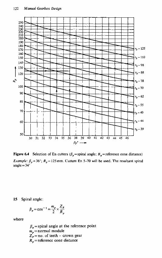
122 Manual Gearbox Design
Figure 6.4 Selection of En cutters (B, =spiral angle; R , = reference cone distance)
Example: B p = 36"; R, = 125 mm. Cutters En 5-70 will be used. The resultant spiral angle = 34"
15 Spiral-angle:
m ZP b, = cos- 1 =2 x - 2 RP
where
p p = spiral angle at the reference point mp = normal module Z,=no. of teeth - crown gear R , = reference cone distance

Oerlikon cycloid spiral bevel gear calculations 123
Figure 6.5 R, = reference cone distance: m,, = normale module; mp = normal module)
Standard cutters (En) - calculation factor k , (R,=inner cone distance;
R.cos/3, mni k , = L = - RpcosBp m p
Starting from the reference point, the spiral angle can be determined at any desired point of the tooth width and consequently the cone distance, R,, for which the established relationship of
Mean cone distance, R, Reference cone distance, R ,
is used.

124 Manual Gearbox Design
Table 6.3 Data of blades, a= 22"30
Finishing Finishing blades Roughing blade blades
Blades (protuberance height) (width of tip) 'kw sB
En 3912 En 3913 En 3915
En 4411 En 4413 En 4415
En 4911 En 4913 En 4915
En 5511 En 5513 En 5515
En 6211 En 6213 En 6215
En 7011 En 7013 En 7015
En 7811 En 7813 En 7815
En 8811 En 8813 En 8815
En 9811 En 9813 En 9814
En 11011 En 11013
En 12511 En 12512
1.0 1.2 1.4 0.5 0.7 0.50 0.63 1.1 1.3 1.5 0.5 0.8 0.8 0.60 0.72 1.3 1.5 1.8 0.5 1.0 1.0 0.70 0.92
1.0 1.2 1.4 0.5 0.7 0.50 0.63 1.2 1.4 1.6 0.5 0.9 0.9 0.60 0.75 1.4 1.7 2.0 0.6 1.0 1.4 1.2 0.75 1.05
1.1 1.3 1.5 0.5 0.8 0.8 0.60 0.68 1.3 1.5 1.8 0.5 1.0 1.0 0.70 0.92 1.5 1.8 2.1 0.7 1.1 1.5 1.4 0.80 1.15
1.2 1.4 1.6 0.5 0.9 0.9 0.60 0.75 1.4 1.7 2.0 0.6 1.0 1.4 1.2 0.75 1.05 1.7 2.0 2.3 0.9 1.3 1.7 1.5 0.90 1.30
1.3 1.5 1.8 0.5 1.0 1.0 0.70 0.92 1.5 1.8 2.1 0.7 1.1 1.5 1.3 0.80 1.15 1.8 2.1 2.4 2.7 1.1 1.6 2.1 1.7 0.95 1.46
1.4 1.7 2.0 0.6 1.0 1.4 1.2 0.75 1.05 1.7 2.0 2.3 0.9 1.3 1.7 1.5 0.90 1.30 1.9 2.2 2.5 2.8 1.3 1.9 2.5 1.8 1.05 1.70
1.5 1.8 2.1 0.7 1.1 1.5 1.3 0.80 1.15 1.8 2.1 2.4 2.7 1.1 1.6 2.1 1.7 0.95 1.46 2.1 2.4 2.7 3.1 1.5 2.0 2.5 3.0 2.1 1.15 1.93
1.7 2.0 2.3 0.9 1.3 1.7 1.5 0.90 1.30 1.9 2.2 2.5 2.8 1.3 1.9 2.5 1.8 1.05 1.70 2.3 2.7 3.1 3.5 1.6 2.2 2.8 3.4 2.3 1.25 2.14
1.8 2.1 2.4 2.7 1.1 1.6 2.1 1.7 0.95 1.46 2.1 2.4 2.7 3.1 1.5 2.0 2.5 3.0 2.1 1.15 1.93 2.3 2.7 3.1 3.5 1.6 2.2 2.8 3.4 2.3 1.25 2.14
1.9 2.2 2.5 2.8 1.3 1.9 2.5 1.8 1.05 1.70 2.3 2.7 3.1 3.5 1.6 2.2 2.8 3.4 2.3 1.25 2.14
2.1 2.4 2.7 3.1 1.5 2.0 2.5 3.0 2.1 1.15 1.93 2.3 2.7 3.1 3.5 1.6 2.2 2.8 3.4 2.3 1.25 2.14
The value p, can then be plotted on the solid line with value 1 in Figure 6.3(a), page 118, and Figure 6.3(b), page 119. From this point, follow the direction of the next curve as far as the point of intersection RJR,. The desired value of the spiral angle at the mean cone distance, p,, can now be read from the ordinate to the left.

Oerlikon cycloid spiral bevel gear calculations 125
Table 6.4 Data of blades, a = 25"
Finishing Finishing blades Roughing blade blades
Blades (protuberance height) (width of tip) ' k w ' 8
En 3912 En 3913 En 3915
En 4411 En 4413 En 4413
En 4911 En 4913 En 4915
En 5511 En 5513 En 5515
En 6211 En 6213 En 6215
En 7011 En 7013 En 7015
En 7811 En 7813 En 7815
En 8811 En 8813 En 8815
En 9811 En 9813 En 9814
En 11011 En llO/L
En 12511 En 12512
1.3 1.5 1.8 0.5 0.7 1.0 0.50 0.60
1.4 1.7 2.0 0.5 0.9 1.2 0.60 0.72
1.3 1.5 1.8 0.5 0.7 1.0 0.50 0.60 1.5 1.8 2.1 0.5 0.8 1.1 1.4 0.60 0.80
1.4 1.7 2.0 0.5 0.9 1.2 0.60 0.72 1.7 2.0 2.3 0.5 0.9 1.3 1.5 0.70 0.94
1.3 1.5 1.8 0.5 0.7 1.0 0.50 0.60 1.5 1.8 2.1 0.5 0.8 1.1 1.3 0.60 0.80 1.8 2.1 2.4 2.7 0.5 1.0 1.5 1.7 0.80 1.14
1.4 1.7 2.0 0.5 0.9 1.2 0.60 0.72 1.7 2.0 2.3 0.5 0.9 1.3 1.5 0.70 0.94 1.9 2.2 2.5 2.8 0.6 1.1 1.6 1.8 0.90 1.34
1.5 1.8 2.1 0.5 0.8 1.1 1.3 0.60 0.80 1.8 2.1 2.4 2.7 0.5 1.0 1.5 1.7 0.80 1.14 2.1 2.4 2.7 3.1 0.7 1.1 1.5 1.9 2.1 0.95 1.54
1.7 2.0 2.3 0.5 0.9 1.3 1.5 0.70 0.94 1.9 2.2 2.5 2.8 0.6 1.1 1.6 1.8 0.90 1.34 2.3 2.7 3.1 3.5 0.9 1.4 1.9 2.4 2.3 1.05 1.72
1.8 2.1 2.4 2.7 0.5 1.0 1.5 1.7 0.80 1.14 2.1 2.4 2.7 3.1 0.7 1.1 1.5 2.1 0.95 1.54 2.3 2.7 3.1 3.5 0.9 1.4 1.9 2.4 2.3 1.05 1.72
1.9 2.2 2.5 2.8 0.6 1.1 1.6 1.8 0.90 1.34 2.3 2.7 3.1 3.5 0.9 1.4 1.9 2.4 2.3 1.05 1.72
2.1 2.4 2.7 3.1 0.7 1.1 1.5 2.1 0.95 1.54 2.3 2.7 3.1 3.5 0.9 1.4 1.9 2.4 2.3 1.05 1.72
The corresponding normal module can be calculated using the following formula: Normal module:
2 x R , mp=- x cos p,
2,

126 Manual Gearbox Design
Figure 6.qa-c) Graphs for cutter spindle tilt: (a) C=O"; (b) C=1"30; (c) C=3"
where
R, = mean cone distance Z,=no. of teeth - crown gear p, = spiral angle at mean cone distance
16 Maximum whole tooth depth. Figures 6.6(a), 6.6(b) and 6.6(c) are used for the determination of the tilt of the cutter spindle. Tilting becomes necessary for very flat ring gears to avoid interference of the returning teeth. 6, is the maximum outer cone angle of the ring gear that can still be cut.
To find the maximum tooth depth admissible, enter a,, = 6, (pitch cone angle) and determine as abscissa the relationship rb/h, where r, is the cutter designation and h the tooth depth.
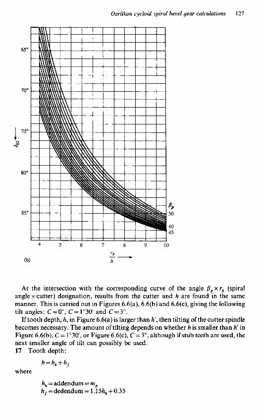
Oerlikon cycloid spiral bevel gear calculations 127
At the intersection with the corresponding curve of the angle / l p x r b (spiral angle x cutter) designation, results from the cutter and h are found in the same manner. This is carried out in Figures 6.6(a), 6.6(b) and 6.6(c), giving the following tilt angles: C=O", C=1"30 and C=3".
If tooth depth, h, in Figure 6.6(a) is larger than h', then tilting of the cutter spindle becomes necessary. The amount of tilting depends on whether h is smaller than h' in Figure 6.6(b), C= l " 3 0 , or Figure 6.6(c), C= 3", although if stub teeth are used, the next smaller angle of tilt can possibly be used. 17 Tooth depth:
h = h, + h, where
h, = addendum = mp h,=dedendum = 1.15hk +0.35

128 Manual Gearbox Design
Figure 6.6 (cont.)
18 Cutter tilt:
C = sin - 1 C (see calculation 16) @=pressure angle - cutter tilt
=a-C, using a for cutters En
19 Auxiliary value k , (see Figure 6.5, page 123) 20 Auxiliary value:
R a= k, x -P x COS B, Ri -
where
k, = auxiliary value (see calculation 19) R , = reference cone distance Ri = inner cone distance B, = spiral angle

Oerlikon cycloid spiral bevel gear calculations 129
21 Profile displacement:
where
@=auxiliary value (see calculation 19) Q =auxiliary value (see calculation 20) R, =inner cone distance 6, = pitch cone angle - pinion
rkw = see Table 6.3 or 6.4, page 124 or 125
22 Profile displacement:
X, = hf - h;,
where
h = dedendum (see calculation 17) h;, =profile displacement (see calculation 21)
23 Corrected addendum - pinion:
h, 1 = h, -k X,
where
h, = addendum (see calculation 17) x, = profile displacement (see calculation 22)
24 Corrected addendum - wheel:
hk2 = h, -x,
where
h k = addendum (see calculation 17) x, = profile displacement (see calculation 22)
25 Corrected dedendum - pinion:
h f , = hf -x,
where
h, = dedendum (see calculation 17) x, =profile displacement (see calculation 22)
26 Corrected dedendum - wheel:
h f 2 = h f +x,
where
h = dedendum (see calculation 17) x, = profile displacement (see calculation 22)

130 Manual Gearbox Design
27 Tooth thickness correction:
where 6, =pitch cone angle mp =normal module
The tooth thickness correction leads to a balance between the dedendum thicknesses of both the pinion and wheel, so that both gears have approximately the same strength. The formula given above has been derived empirically. 28 Backlash:
j = 0.05 + 0.03mp
mp = normal module where
The backlash is dependent on the size of the gears, and therefore it is given as a
The value 0.05 is an allowance for thermal expansion. function of the normal module at the reference point.
Strength calculation
The strength calculation is generally carried out as a verification of the gear design and gains in significance if its results can be compared with actual experience obtained from other gear pairs.
The strength calculation is founded on an ideal, rigid construction for both the gear housing and the bearings. Consequently, it may be that heavily oversized gears become damaged because the tooth contact has shifted towards the ends of the teeth under elastic deformation, with the resultant rupture in these areas. Furthermore, the oil film may break down between the tooth flanks under the elastic deformation, leading to a seizure problem or heavy wear. The strength calculation is based on complementary spur gears; this approach, however, does not fully consider the tooth form which is dependent on the cutting method.
To determine the external forces on the gears, the calculation is based on the circumferential force at the centre of the tooth facewidth, which can be calculated from the torque of the pinion shaft, as follows:
Torque at pinion = Engine torque x Lowest gear ratio
where the corresponding revolutions of the pinion
= Engine rpm x Lowest gear ratio
For vehicles, the slipping moment for the tyres must be included in the external force calculation. If the engine torque is larger than the slipping moment, the calculation should be based on the slipping moment, which is calculated as follows:
2 1 M d R = p x Q x rw x x -
z, is,

Oerlikon cycloid spiral bevel gear calculations 131
where M,, = slipping moment
p = coefficient of friction; when unknown use: 0.5 for passenger cars 0.8 for trucks and tractors
Q=axle load r , = rolling radius of tyres 2, =no. of teeth - pinion 2, =no. of teeth - mating gear is, = factor for possible intermediate spur gears; if unknown, is, = 1
Note: If Q is in kilograms and r , is in metres, then M,, is in metre-kilograms, but where Q is in pounds and r , is in feet, then M,, is in pounds-feet.
The circumferential force which results from the torque is calculated at the centre of the tooth facewidth using the following formulae:
r,, = R , x sin 6, (mm ) :. circumferential force
where rml =mean radius - pinion (mm) R, = mean pitch cone distance 6, =pitch cone angle - pinion P , = circumferential force
M , = torque at pinion - using either maximum torque at pinion or torque allowable by slipping moment
The circumferential speed at the effective radius is calculated as follows:
rml x n x n, 30 OOO (mb) V =
where I/= circumferential speed
n, = rpm - pinion rml =mean radius - pinion (mm)
The bending stress is calculated using the Lewis formulae which compare the tooth of the gear with a beam of identical strength. The beam has a parabolic profile and is inscribed in the outline of the tooth. Determine for this purpose the complementary spur gear at the centre of the tooth, thus converting the spiral bevel gear to an equivalent spur gear. The Lewis formulae assume that the entire circumferential force is transmitted by a single tooth.
The force P i which acts on the addendum and which is equal to
P" cos B k
is in proportion to P , as are the corresponding radii. Since the ratio is approximately 1 : 1, then PI = P , can be used.

132 Manual Gearbox Design
The beam of identical strength is calculated using the following formula:
b x S : 6 Pub x de=- gb
where
Pib = permissible circumferential force (kg) d,=effective tooth depth (mm) b = tooth facewidth (mm)
S , = tooth thickness at dedendum (mm) ab=rupture strength of material (use 1oO-130 kg/mm2 for most case-
As the preceding formula does not take into account the circumferential speed and thus the dynamic forces of the gears, a speed factor must be included. This speed factor can be calculated using the following formula:
hardening steels)
5.5
f ,=5.5+J;
where
f, = speed factor u = circumferential speed (m/s)
Therefore, the permissible ultimate load is calculated using the formula:
b x S; p =- 6 x de Ob x f o (kg) ub
where
P u b =permissible ultimate load (kg) b = tooth facewidth (mm)
S , = tooth thickness at dedendum (mm) d,=effective tooth depth (mm) Ob = rupture strength of material f, =speed factor
Having completed the calculation sequences for the crown wheel and pinion, the designer should use the facilities offered by both the Klingelnberg and Oerlikon companies, who provide full design calculation and production advice, as the development of any new transmission design calls for very close collaboration between the design, production and test departments.
Stage 1 consists of the series of calculations to be carried out by the design team to arrive at the dimensions for:
(a) the gears (b) the bearings and shafts required to cope with the power through the system (c) the torque input and speed (d) any reduction ratios required in the overall drive line

Oerlikon cycloid spiral bevel gear calculations 133
Stage 2 is the preparation of an overall scheme and the detailed working drawings using the calculated data. During this stage, close consultations between both the design and production departments can avoid exaggerated precision requirements by arriving at a functional yet reasonably priced assembly which does not affect the performance of the finished product.
Stage 3 is the production and assembly of the components to produce prototypes. This calls for careful precision workmanship and logging of details.
Stage 4 requires both the design and development departments to co-operate in the testing and development of the transmission, to check that the calculated data and the requirements of the customer coincide with the realistic running characteris- tics of the unit.
It must always be remembered that during these development stages, problems may arise, especially in the following areas:
(a) the specification of inadequate strength transmission members, Le. housings,
(b) inadequate machining quality and finish of components (c) faulty mounting of gear sets, i.e. out-of-line or inadequate support strength
Any one of these may lead to unfavourable shifts of the load-bearing patterns and as a result may set up excessive stresses in normal service, leading to surface damage or tooth fracture due to bending or shear loading.
The dimensional, production or mounting faults will determine the real axle load-bearing capacity, which may diverge substantially from the original calculated data.
Optimum running properties and maximum load-bearing capacity will only be obtained when the load-bearing contact pattern of the gear set lies within the limits of the tooth flank surfaces in all the load stages and no excessive localized surface stresses occur. To achieve this aim, the shape, size and position of the pattern under light load should be selected to avoid all load concentrations at the tooth limits. In spite of any unavoidable bending deflection, displacements, manufacturing and mounting tolerances, and in view ofthe complicated distribution of forces in the gear drive unit, it is impossible to predetermine exactly the load pattern shifts which will occur. Only load deflection tests on the complete drive unit on a development rig will provide unequivocal data which the design team can use in the preparation of the finalized production unit. These load-deflection tests should ideally be carried out on the development unit both on the development rig and in a development vehicle during test drives.
shafts, bearings or gears

7 Gearbox design - rear-engined racing cars
Basic aims
The design of any gearbox to be used for racing purposes must always have the following aims:
(a) provide the maximum possible efficiency in all gears (b) be the minimum possible weight while being capable of coping with the requisite
torque throughput (c) have an overall simplicity in design and, more importantly, in assembly, as ratio
changing and maintenance often have to be carried out under fairly primitive conditions
(d) require the minimum amount of time and effort for maintenance -this point is effected by the simplicity in design and assembly
(e) reduce the number of components to be removed, when changing internal gear ratios, to an absolute minimum, so that ratio changing can be carried out as quickly as possible
(f) provide a positive method for locking the pinion in position after completing the meshing procedure with the crown wheel, to ensure that the meshing is not disturbed when changing internal gear ratios or presetting gear selection mechanisms
These aims are explained more fully in the following paragraphs. The necessity for maximum efficiency is fairly obvious, as the need to apply the
maximum amount of the available engine torque to the road wheels must be an essential ingredient in any racing car design.
The need for a minimum possible weight to cope with the required torque throughput is an obvious way to assist the chassis designer, who is usually working to achieve a specified minimum overall weight for the complete car. Any weight in excess of this specified minimum imposes a penalty on the car performance, as the excess weight must be propelled around the circuit. On the other hand, if the car’s overall weight is below the minimum target, then make-up weight to be added to the

Gearbox design - rear-engined racing cars 135
car can be applied in the most advantageous positions to give an overall balance to the car.
An overall simplicity in both design and assembly means less chance of failure 2nd fewer component parts required as spares. Another advantage is that less equipment is required for assembly and maintenance when the work is carried out at the racing circuit.
A minimum amount of time and effort for maintenance obviously points to a successful gearbox design, with low overhaul costs and few replacement compo- nents to purchase, as well as leaving more time for car preparation and engine preparation and tuning to suit the individual circuit and atmospheric conditions.
Keeping the number of components to be removed, when changing internal ratios, to an absolute minimum obviously means quicker ratio changes with fewer components to be checked after completing the ratio change. This quicker ratio change is very important, in view of the very narrow effective engine revolution range available from most racing power units. This can vary between 2000 and 4000rpm, and regardless of the type of circuit along with the relevant weather conditions this effective revolution range must be maintained through all the gearbox ratios in order to obtain ultimate speeds and consequently achieve the fastest lap times possible.
Providing a positive method for locking the pinion in position after completing the meshing procedure with the crown wheel means that, regardless of the number of internal ratio changes, the crown wheel and pinion mesh is undisturbed. Also, provided that the initial mesh is correct, the best possible life for both crown wheel and pinion will be obtained.
The racing-type gearboxes are in the majority of cases designed with four or more forward gear ratios, plus the mandatory reverse gear ratio required by the present-day international racing regulations. The gear change system in the majority of racing gearboxes does not use synchromesh units for the gear engagement, but consists of a ‘crash-change’ type of system, with gear engagement through interlocking face dogs. The gearbox can be either in line with the chassis or transverse, dependent upon the car designer’s requirements, both arrangements having certain advantages over each other.
In-line shaft arrangement
The first part of this chapter will cover the design of the in-line gearbox which, over the past few decades, has been used in rear engine cars as a transaxle unit bolted onto the rear end face of an in-line engine in the majority ofcases. With this type of layout, the drive from the engine comes into the gearbox via a clutch or input shaft, direct from the clutch which is usually mounted on the rear end of the engine crankshaft. This input shaft is usually positively located in the front of the gearbox casing by means of a ball bearing or some similar location bearing and locates by means of an internal-external spline arrangement into the hub of the clutch. The gearbox end of the input shaft passes under the differential and positively connects to an intermediate shaft in the majority of designs, using an external spline or serration on the input shaft which locates into an internal spline or serration in the end of the

136 Manual Gearbox Design
intermediate shaft. With this arrangement, the input shaft, the intermediate shaft and the crankshaft are all in line.
The input shaft is used as a quill shaft drive and, by choosing the correct material for this shaft, some of the shock loadings imparted by the engine during standing or racing starts and snatched gear changes are absorbed by the torsional damping action of the shaft, thus providing some protection against these shock loadings for the gearbox internals. The location bearing on the input shaft provides it with both radial and thrust location, ensuring that the shaft remains static with no ‘end-wise’ movement as the clutch is engaged and disengaged. The splined or serrated end of the input shaft located in the intermediate shaft is left free to move longitudinally to take up manufacturing tolerances or any movement due to thermal expansion when the gearbox is hot.
Ideally, the intermediate shaft should be located at the forward end, preferably directly over the splined or serrated internal area which provides the drive between the input shaft and the intermediate shaft. The radial and fore and aft location of the intermediate shaft is usually in the form of a ball bearing, possibly a double-row type, the size being dependent upon the loads created by the engine torque, the gear separating load and the gear tangential load, on the internal gear ratios. With this arrangement, the rear end of the intermediate shaft can be located by a roller-type bearing, with its outer ring positively located in the gearbox rear cover.
The pinion or output shaft in this form of racing gearbox is usually positioned above the intermediate shaft. In the majority of arrangements the pinion shaft is on the centre-line of the crown wheel. As very few racing gearboxes have been produced with hypoid or offset pinions and as the crown wheel centre-line is usually fixed by the static road wheel centre-line along with the suspension movement, the internal gear ratio centres can be fixed. The pinion shaft should also be located in the gearbox casing at the front end as close as possible to the pinion teeth, by means of either a double row ball bearing or a pair of taper roller bearings mounted back to back, and positioned directly above the location bearings on the intermediate shaft. The pinion shaft location bearing arrangement must be capable of coping with the pinion thrust load and the larger portion of the radial loads from both the pinion and the internal gear ratios.
Locating the bearings as close as possible to the pinion teeth helps to eliminate most of the difficulties that can occur due to material growth caused by thermal expansion as the gearbox heats up, which will cause problems with the backlash in the crown wheel and pinion mesh. If the pinion location bearing were to be positioned further back along the shaft, the differential growth between casing and shaft would cause large variations in the running backlash. This in turn can lead to gear failure. It is preferable that the pinion location bearings are positively fixed on the pinion shaft, either by using an adjustable spacer and a heavy-duty circlip or a locking ring nut directly behind the bearings. With this arrangement, the meshing of the crown wheel and pinion is isolated and will in no way be affected when either the gearbox internal ratios are being changed or the internal selector mechanism is either being initially set up or adjusted.
The rear end of the pinion shaft can also be mounted in a similar way to the intermediate shaft, using a roller bearing located in the gearbox rear cover. With this type of bearing, allowance is made for lateral movement of the shaft, which takes

Gearbox design - rear-engined racing cars 137
care of the build up of tolerances which occurs in the manufacture and assembly of the internal gear pack into the gearbox casing. The overall length of the internal gear pack will be the deciding factor in fixing the distance between the location bearing and the roller bearing on both the pinion and intermediate shafts. If the outer track or race of both shaft roller bearings is positively located in the gearbox rear cover, this allows the whole of the internal pack to be exposed when the rear cover is removed. If the rear cover to the main casing joint line is designed to be as near as possible to the shaft location bearings, this facilitates the quick changing of internal gear ratios and the accurate adjustment of the selector mechanism and checking of the meshing of all the gears in the internal gear pack.
Internal gear arrangement
The internal gear ratios in a racing gearbox are usually straight-cut spur gears, and of each ratio pair one gear is positively located on the intermediate shaft using either a spline or serration with its mating gear being mounted on the pinion shaft, but free to rotate. The gears can either be mounted on a solid bush-type bearing or a needle roller. Caged needle rollers have proved to be the preferable choice for this application, especially as the rotational speeds have increased, as they are less prone to problems such as plucking, picking-up and seizure than the solid bush-type bearing, which in turn may prove to be more compact. The caged needle roller bearing is also better able to cope with the small particles of metal that are always present in a ‘crash-change’ type of gearbox under operational conditions.
The internal gear ratios can be arranged with either the highest or lowest gear ratio adjacent to the shaft location bearings but, as maximum load is experienced in first gear as the car accelerates away from a standing start, it is usual to fit the lowest gear ratio adjacent to the shaft location bearings. A range of varying ratios for the internal gears, all of which are fully interchangeable within the gearbox, is required to enable the engineers to set the car up to race on a variety of different types of circuits under various conditions, while ensuring that the engine revolutions are maintained in the most effective revolution range.
The free-running gears of these internal ratios have face dogs cut on one side of the gear only and are usually mounted on a sleeve which has internal splines or serrations which locate it on the splines or serrations on the pinion shaft. The outside of this sleeve has bearing diameters at each end on which the caged needle rollers in the gears are mounted.
Face-dog selectors
The gears mounted on each end of the sleeve are fitted so that their face dogs are facing each other. Between the two gears the sleeve has a raised portion which is splined or serrated. This must be of large enough diameter that the end-faces of the spline or serration provide an adequate thrust face to retain the free-running gears in position, with their face dogs overhanging the central splines or serrations. Between the face dogs on the free-running gear pairs is the engaging dog ring, which is located

138 Manual Gearbox Design
on the raised spline or serration. It has face dogs on each side and when it is centralized there should be a minimum of 0.050 in clearance between the extreme ends of the face dogs on the engaging dog ring and the dogs on the pair of free-running gears. This means that one engaging dog ring is required to operate a maximum of two internal gear ratios.
The face dogs on both the engaging dog ring and the pair of free-running gears should be diametrically equal on the inside and almost equal on the outside. The dog ring should be free to slide on the splines or serrations to allow the dog ring face dogs to engage with the face dogs on the free-running gears.
While the face dogs on the engaging dog rings and the free-running gears of the internal ratios are equal in diameters, to enable quick gear changes to be made, an angular side clearance of approximately 0.125 in should be allowed between the face dogs on the engaging dog rings and those on the free-running gears radially when viewed on the face of the dogs. Great care must be taken when designing these face dogs to ensure that full face contact is made when the angular side clearance is taken up. The number of dogs on both gears and engaging dog rings must be equal, and the number of dogs used will depend on the diameters, both internal and external, of the engaging dog ring and free-running gear face dogs and the loading on these dogs due to the torque to be transmitted.
To prevent the face dogs slipping out of engagement while under load, they should be manufactured with a retaining reverse angle of between 5" and 7F on their mating faces. This means that the nose or outer end of the dog is the maximum width to be used when calculating the side clearance. However, even with this reverse angle, full face contact must be maintained. The majority of racing gearboxes use this type of 'crash-change' system and not the synchromesh system as used in road vehicle transmissions. This is because there is an overall weight saving and a reduction in overall length and frictional losses and, most importantly, a quicker more positive gear change movement.
The synchromesh system tends to result in a momentary time lag, as the cones synchronize the differential speeds of the gear and dog ring which results in a slower gear change movement. The cones synchronize speeds using friction on their tapered shanks, resulting in frictional losses, and the assembly of the synchromesh unit is more complicated and consists of more components resulting in longer maintenance times and, for the same torque loading, an increase in overall size and weight.
The end clamping of the internal gear pack and bearings, together with the grindable or adjustable spacers or washers necessary to retain or correctly space the internal gear ratios, is by means of a thread either on the outside or in the bore of both the pinion and intermediate shafts along with a mating nut or setscrew. The hand of these two threads should be carefully chosen -it is usual to select the hand of thread to ensure that the nut or setscrew is being tightening up as the shafts rotate and accelerate. The major diameters or any external thread used must obviously be below both the root diameter of the spline and the bearing diameter on the rear end of the shaft in question. A further point to be taken into account is to ensure that the outer dimension of the nut or setscrew head is capable of passing through the inside diameter of the roller bearing outer track to be used on their respective shafts. Also,

Gearbox design - rear-engined racing cars 139
if as previously stated the bearing outer tracks are positively located in the gearbox rear cover, then the gearbox internal pack comprising
(a) the shafts, both intermediate and output (b) the internal gear ratios and needle roller bearings (c) the engaging dog sleeves and engaging dogs (d) the location bearings, spacers and roller bearing inner assemblies, together with
can be built into the gearbox casing as a complete unit. With this facility available and the previously mentioned point, to keep the main
casing to rear cover joint line as close as possible to the location bearings, then by producing a plate of roller bearing width, bored to fit snugly over the rollers of the roller bearing inner assemblies at the correct shaft centres, i.e. with bores identical to the respective roller bearing outer track, then all the internal gear pack running clearances, gear tooth meshing and the engagement of the gear face dogs can be readily checked at this stage of the assembly. Thus, when the time arrives to fit the rear cover, the internals need not be disturbed. One important check to be made at this stage is to ensure that clearance is present between the outer ends of the engaging dog ring face dogs and the end of the face dogs on all the gears when the dog ring is centralized. This also ensures that the changing of internal gear ratios is relatively simple and quick, as well as reasonably foolproof, which is one of the main essentials of a racing transmission.
It should be remembered at this point that the engaging dog rings must be moved into and out of engagement with the gears on either side of them. This can be done by one of two methods:
(a) with a flange raised at the centre of the overall length of the engaging dog ring,
(b) with a groove at the centre of the overall length of the engaging dog ring, with
Therefore, it must be realized that the distance between the inward-facing dogs of each pair of free-running gears must be sufficient to allow clearance between the flanges of either the selector fork or the engaging dog ring and the ends of the face dogs on the gears when the engaging dog is moved into the engaged position.
the clamping nut or setscrew
shrouded by a grooved selector fork
raised side flanges in which a flanged selector fork fits
Bearing arrangement
The bearing arrangement, as laid out in the previous pages, is not always possible due to the centres being too small between the pinion and intermediate shafts to leave sufficient material between the shaft diameters to permit the two correct size location bearings to be mounted directly above each other. The front end location bearing arrangement, however, is the superior system, being the simplest and quickest fqr both assembly and ratio changing and the most accurate method for initial build and checking of the internal gear pack.
In arrangements of the internal gear pack assembly, where the shaft centres are

140 Manual Gearbox Design
too close to allow the two location bearings to be mounted at the same end of the shafts, the designer must find an alternative method. But whatever system is used, it must always be remembered that the best position for the pinion shaft location bearing is as close as possible to the bevel gear mesh.
In this circumstance, the alternative arrangement is virtually decided for the designer, and results in moving the intermediate shaft location bearing to the rear end of the shaft and positively locating the bearing in the gearbox rear cover. Then if material between the two shafts does not permit the use of the two roller bearings, as described previously, even if the intermediate shaft roller bearing were moved to the front end of the shaft, these roller bearings can be replaced by needle roller bearings which are physically smaller overall in outside diameter for bearings of the same load-carrying capacity.
However, this arrangement of the bearings leads to some difficulties during assembly and ratio changing. This is because although the free-running gears, engaging dog sleeves, engaging dog rings, spacers and pinion location bearing can still be built onto the pinion shaft in the gearbox casing, the difficulties commence when the splined or serrated bores of the driving gears are being fed onto the intermediate shaft in their correct position while feeding the rear cover, complete with the intermediate shaft, onto the needle roller mounted on the rear end of the pinion shaft and the nose of the intermediate shaft into the needle roller mounted below the pinion location bearing, and at the same time locating the intermediate shaft internal spline into position on the splined end of the input shaft. These problems are made somewhat more difficult as they must be carried out mainly by feel. As a result, the following points arise with this type of bearing arrangement, in addition to the assembly difficulties already listed :
(a) the internal gear tooth meshing and backlash cannot be positively checked (b) internal gear tooth facewidth alignment cannot easily be visually checked (c) the face dog side clearances cannot be centralized and visually checked with the
selector forks in their operating position, as the location for the selector fork shafts is in the rear cover
(d) the face dog engagement depth is not easily checked with the engaging dog ring located in the various internal gears
(e) due to the location bearings for the pinion shaft and the intermediate shaft being at opposite ends of the internal gear pack and mounted in two different castings, the end-to-end movement and positioning of the internal gear pack are subject to the build up of the machining tolerances on both the internal components and the castings and are also affected by the expansion differentials of the metals used for the shafts and castings
Having arrived at the overall design parameters for the gearbox internal gear pack and the shafts, the designer is now faced with the task of stressing out each of the components to arrive at the size of shafts and gears required to cope with the maximum torque to be absorbed by the transmission under full racing conditions. This must include the high shock loadings that are imported by the racing standing starts and by ‘clutch-snapping’ during gear changes when the driver is under severe pressure.
In order to carry out the stressing programme, the materials and types of heat

Gearbox design - rear-engined racing cars 141
treatment to be used in the manufacture of the various components must be selected at this stage and, as the racing-type transmission needs to be kept down to an absolute minimum weight and overall size, the highest grades of material along with the more complex heat treatments are utilized. This is particularly so in the highly competitive and very expensive Formula One racing transmissions.
Having completed the stressing of the shafts and gears and knowing the minimum size the components that are to be used, then the actual transmission layout can be commenced and gradually built up. Eventually the room available for the location and supporting bearings will become apparent and, by calculating the pinion thrust load and the radial loads for all the gears involved, then by using the maximum radial load along with the thrust load the size of the pinion bearings can be arrived at. The intermediate shaft bearings are selected to cope with only radial loads and so are usually smaller in size. It must always be remembered that these bearings must not only becapable of coping with the loads involved, but also the shaft speeds which in the Formula One transmission of today are very high. However, one point to ease this problem is that the running periods for the transmission are reasonably short, and the lubrication and maintenance are usually very good. The selected bearings can now be drawn onto the transmission layout.
Regardless of which of the two bearing arrangements is used for the pinion and intermediate shafts, the method ofengagement for the internal gears is the same, and consists of the following: the engaging dog ring is moved sideways so that the face dogs on one of its faces engage with the face dogs on the required internal gear ratio; this sideways movement of the engaging dog ring is made by moving the selector fork in question - the selector mechanism will be described later in this chapter.
Crown wheel and pinion layout
Drive to the drive shafts and rear wheels from the pinion shaft is via the pinion and its mating crown wheel. These can either be straight cut or spiral bevel gears, and the crown wheel is mounted on the outside diameter of the outer casing of the differential which divides the drive to the two rear wheels. This differential unit is mounted between a pair of location bearings which can either be angular contact ball bearings or taper roller bearings, which are located in the gearbox bearings, which are located in the gearbox casing. Three different methods have, in the past, been used to locate these bearings in the gearbox casing, as follows:
1 In the first method, they are located in a pair of side covers which are spigoted into the sides of the gearbox casing and bolted in position.
This system weakens the gearbox main casing in the differential area, as the holes for the side cover spigots must be large enough for the crown wheel and differential assembly to pass through and therefore a large area of solid casting material is removed and replaced by covers which rely on spigoting and clamping load to provide a solid mass in the area. 2 In the second method, only one side cover is used, leaving the opposite side of the gearbox main casing complete. With this arrangement, one location bearing is mounted in the casing while the second one is mounted in a spigoted and bolted side

142 Manual Gearbox Design
cover. The side cover must be on the side of the casing which allows the crown wheel and differential to be fitted and removed with the pinion in position. This must be located on the correct side to ensure that the pinion drives the crown wheel in the correct rotation for the road wheel direction.
This system is obviously stronger than the first method, as one side of the main casing remains complete and can be ribbed-up to strengthen the area, but the opposite side - as in the first method -is weakened by the removal of material for the spigoted side cover. 3 The third method uses a main casing and separate front cover in place of the one-piece gearbox casing, the split line between casing and front cover being at the centre-line of the differential assembly so that half of each location bearing housing is machined in the main casing and half in the front cover.
With this arrangement it has been found to be advisable to mount the location bearings in steel housings which are then mounted in the split bores in the two castings. This system provides stability to the area, as the material used for the gearbox castings is either magnesium or aluminium in very light sections and with the loads imparted into the casings in this area by the engine torque, crown wheel thrust and loads from any suspension units that are mounted on the casings could result in interface movement at the split line. Therefore, by using the outside diameter of the two steel bearing housings as a form of dowel and positively clamping the front cover and gearbox casing around them, any interface movement will be severely restricted.
Because the separating force created between the crown wheel and pinion is acting across this face joint, it is essential that a strong, positive clamping system is used at the front cover/gearbox casing joint face, for unless a positive location is provided for the crown wheel/differential assembly, severe problems will be encountered in the meshing between the crown wheel and pinion, with resultant loss or gain in backlash, and increasing noise, leading to gear tooth failures when running under load. Furthermore, the joint line must under all conditions remain absolutely leak- proof in order to prevent the loss of gearbox lubricant or the inclusion of foreign matter in the lubricant.
With either of the first two arrangements it is obvious that by removing metal from the main casing to form the spigot diameters for the differential side covers, the casing is weakened. Although some strength is added when the side covers are spigoted and bolted in position, this area of the gearbox casing will easily be the weakest part of the assembly, it being the most heavily loaded area, unless careful design arrangements are incorporated. The third arrangement, with the joint face at the centre-line of the differential, has certain advantages over the other two as follows:
1 By designing the bolting arrangement between the mating faces very carefully, the gearbox main casing/front cover assembly can be produced with a very strong joint. 2 By employing the use of a pair of slave-bearing caps to hold the differen- tial/crown wheel assembly in position in the gearbox casing and with the pinion assembled in the casing, then the meshing between crown wheel and pinion can be very positive and accurate, as the whole meshing operation during assembly is in full

Gearbox design - rear-engined racing cars 143
view, thereby providing a positive checking facility as the two gears are rolled together. 3 With this arrangement, the gearbox main casing, complete with the internal gear pack, can be removed from the car, leaving the front cover complete with the differential assembly and axle half-shafts in position.
Diftperential location and type
The majority of racing gearboxes are designed with the differential between the clutch and the internal gear pack in the in-line gearbox and engine arrangement, with the input shaft or quill shaft running below the differential and along the tooth face side of the crown wheel.
Other types of layout have been used with the in-line gearbox and engine arrangement. These include a layout where the internal gear pack is mounted directly behind the clutch and the crown wheel and differential assembly sited behind the internal gear pack. With this arrangement, the pinion shaft is reversed and the crown wheel is on the opposite side of the pinion.
Another system used had the clutch assembly mounted behind the in-line gearbox which was bolted onto the rear face of the engine. The crown wheel and differential assembly in this system was between the rear face of the engine and the internal gear pack. This system used a clutch that was in effect reversed to reduce the rotating mass. The clutch was driven by a long quill shaft from the rear of the crankshaft passing through the gearbox, down the centre of the intermediate shaft, with no connection to the clutch centre. The outer ring of the clutch was in turn connected to the rear end of the intermediate shaft to provide drive to the internal gear pack.
With both of these layouts, which were in turn used for specific reasons, the main problems encountered were:
Layout I. With the difficult problem of keeping the wheelbase of the car within reasonable proportions, the rear-mounted differential had another major defect from the racing engineer’s point of view, in that the maintenance of the assembly was more difficult and more components had to be removed when changing the internal gear ratios, both of which meant more time taken up and as a consequence a greater chance of mistakes being made.
Layout 2 . With the rear-mounted clutch, the main problem encountered was to design a gear change system which was quick and positive, despite the increased rotating masses which were encountered.
Having decided on the differential unit’s location, the size of the unit can now be assessed by using the maximum engine torque, the lowest internal gear ratio to be used and the crown wheel and pinion ratio. Multiplying these three together gives the maximum torque that the differential must cope with, and thus the size of unit can be fixed. But before this calculation can be made, the crown wheel and pinion ratio and the internal gear ratios must be arrived at. This is done by deciding the maximum road speed the vehicle is required to achieve, using the maximum engine revolutions per minute and the road wheel or tyre-rolling radius, which should be
144 Manual Gearbox Design
available from the tyre manufacturer. Then by using the following formula the overall gear ratio, both crown wheel and pinion, and the internal gear ratio, can be calculated as follows:
Overall gear ratio
Road speed (mph) x 36 x 1760 -
Engine (rpm) x 60 x 2n x Tyre rolling radius
Using a ratio of 1 : 1 for the highest internal gear ratio, the calculated overall gear ratio becomes the crown wheel and pinion ratio and by using this ratio, along with the space available for the crown wheel, always remembering that this gear must fit over the differential which has been selected, then the number of teeth on the crown wheel and pinion for various values of circular pitch can be arrived at, using the maximum pitch circle diameter possible for the crown wheel and obtaining the maximum number of teeth possible. Dividing this number of teeth by the calculated overall gear ratio gives the number of teeth on the pinion. Obviously the numbers of teeth must be whole and therefore some adjustments in sizes must be made. The circular pitch to be used must be decided by using the maximum torque to be coped with, at the crown wheel and pinion, the facewidth of the gears and the tooth thickness and fully stressing the gears.
As mentioned earlier in this book, it is essential that when the designer is fixing the position of the differential assembly within the gearbox, the overall car design is also taken into account, as the centre-line of the differential assembly and the centre of the road driving wheel must be kept closely allied. This is so that the angle of the drive shafts linking the differential drive to the wheel stub axle is kept to a minimum for the full range of movement of the road wheel when the suspension is active as the car is in motion. The object of keeping the angular movement in the drive shaft universal joints to an absolute minimum is that it allows the use of smaller universal joints and reduces friction and wear, along with keeping weight down and reducing the losses in efficiency in the drive-line, all of which are very important factors in racing car design.
Varying designs of differential have been used in racing gearboxes. Whichever one is selected, it must cope with the following:
(a) the car design and the type of racing for which it is to be used, i.e. hill climbing,
(b) the varying types ofcircuit upon which the car is to be raced - twisty or with long
(c) the conditions which are likely to be encountered on the varying circuits, such as
(d) the best compromise to suit the team drivers’ preferences and driving techniques
The majority of racing gearboxes are fitted with one or another type of limited slip differential. All the different types of limited slip differential have the same object in view, which is to provide the maximum positive drive to the road wheels, regardless of the varying track surfaces and weather conditions encountered.
The standard gear-type differential which is fitted to the average passenger car is commonly known as a balanced torque differential, but it has a major disadvantage
road or track racing or endurance racing
fast straights, flat or hilly, etc.
surface changes, and the types of weather including varying winds

Gearbox design - rear-engined racing cars 145
in the fact that when the tractive effort of one road wheel is reduced because of a change in load on that wheel, or the fact that the wheel is on slippery ground with a low surface coefficient, then the tractive effort which can be absorbed by the opposite side road wheel is reduced by a similar amount. The torque at the road wheel with the least traction, multiplied by the number of road driving wheels, gives the total tractive effort of the vehicle.
Certain classes of racing cars must use the standard gear-type differential, as this is laid down in the regulations for their class, and in these circumstances all the competitors start on equal terms.
In the types of racing cars where a free choice of differential is permissible, the designer will always be searching for a differential that will increase the torque absorbed by the driving wheel with the high tractive effort as the opposite wheel loses tractive effort, i.e. transfer as much of the lost tractive effort from one wheel to its opposite driving wheel as possible. In order to make this possible, some means of providing a resistance to the differential action of the unit had to be produced, and various design approaches have been made to solve this problem, resulting in a varied range of ‘limited slip’ or ‘spin resistant’ differentials being available.
Probably the simplest form of these improved resistance differentials takes a standard equal torque gear-type differential, consisting of a casing with one or two driving pins or axles and two or four pinions, depending on which arrangement is required to absorb the torque at the differential. These idler pinions mesh with the wheel drive gears and utilize the sliding friction between the rotating gears. This is increased by adding a cam plate behind both of the wheel drive gears, thus providing a mechanical means of forcing the gears tightly into mesh with the pinions, which increases the sliding friction between gears and pinions.
It is more usual, however, in a racing gearbox, especially Formula One, to use either a ‘Z.F. Limited Slip Differential’ or a ‘Powr-Lok Differential’
The Z.F. Limited Slip Differential consists of an inner cam ring with 11 external cam lobes and an outer cam ring with 13 internal cam lobes. Fitted between these cam rings and located in the cam lobes are eight plungers with radiused tops and bottoms that run in the cam forms and flat sides. These plungers, which are commonly referred to as ‘pawls’ and ‘stones’, are housed in slots which are machined so that the flat sides of the plungers are an easy slide fit in them. The slots are machined in an extension nosepiece of the differential casing, to which the crown wheel is bolted. The inside and outside diameters of the nosepiece are machined so that clearance is available between them and the peaks of both the internal and external cam forms. The cam rings are both designed with hubs which are splined internally, and when the differential is assembled the hubs are on opposite sides of the unit. These splines provide the means for drive from the crown wheel through drive shafts or axle shafts to the road wheels.
Although both road wheels are capable of absorbing equal torque, the eight plungers exert a force on the flanks of the cams on both the inner and outer cam rings, so that the whole differential assembly rotates as a mass. If one road wheel contacts a surface with low resistance, the accelerative reaction of the spinning road wheel increases the friction between the plungers and the cam profiles by simply moving the cam to which the slipping wheel is connected. Thus the plungers become wedged between a higher section or area of the outer cam profiles and the mating

146 Manual Gearbox Design
inner cam profiles. While this action is taking place, the profiled plunger must slide up or down the cam flanks, and this frictional force which the sliding motion creates is reflected as increased torque at the high traction wheel. This principle also applies when the vehicle rounds a corner or is travelling in anything other than a straight line.
The main fault in the action of this type of differential is its roughness or harshness in action, probably due to the necessary internal clearances in the mechanism, and it is possible that its operation will be felt by the driver of the vehicle especially at low speeds. This possibility is much greater in a racing car, where the driver virtually sits on and is strapped to the car structure.
Apart from this, the cam and plunger differential has the following advantages:
(a) faultless compensation of wheel speeds when cornering (b) even forque transmission to the road wheels (c) the possibility of starting off from rest even when one driving wheel is standing
(d) no wheel-spin, relative to each other, giving smoother control, less tyre wear and
(e) skidding is almost impossible from the driving force, due to the high internal
(f) simple construction with no thrust washers or clutch plates to assemble or suffer
(g) ease of maintenance and replacement of parts, and the checking of efficiency (h) vast experience in use and development, which have provided a unit which is
It is essential to realize that the locking effect in this type of differential is entirely dependent upon the angles of the cam profiles, and is in no way affected by the modification of the overall diameter of the standard pawl or to the pitch circle diameter at which the pawls are designed to operate.
The Powr-Lok Differential, designed by the Powr-Lok Corporation of America, incorporates many research and development improvements made by the Dana Corporation. The differential is manufactured and marketed in the UK, under licence, by Salisbury Transmissions, who operate a close technical liaison with the Dana Corporation.
The Powr-Lok unit basically consists of four pinions mounted one on each end of two separate cross-pins which are at right angles to each other.At the very ends of both cross-pins, outside the pinions, is a ‘V-form’ cam, machined on one side of the cross-pin only, i.e. four V-form cams in total. The cams on the cross-pins locate on a mating V-form machined in both halves of the two-part differential casing.
Between each cam and its respective pinion teeth is a shoulder which is machined on the pinion. The diameter of this shoulder, which is slightly smaller than the pinion tooth root diameter, is in contact with the lip of a cup. These cups surround the two-wheel drive gears, which are mounted one on each side of the four pinions. The teeth of the two-wheel drive gears mesh with the teeth of all four pinions. Behind each of the cups is a plate clutch whose individual plates are alternately connected by internal and external splines to the wheel drive gear and the differential casing. Between both outer clutch plates and the casing is a Belleville washer, which applies
on a slippery surface
safer road holding
resistance of the differential
from wear problems
capable of holding its own on the present-day markets.

Gearbox design - rear-engined racing cars 147
a constant pre-load torque to the clutch plates, which are specially treated with a form of sintering to obtain the maximum frictional characteristics. As torque is applied to the differential, the cams of the cross-pins ride up the mating cam faces in the differential casing, thus applying a thrust load between the pinion shoulder and the lip of the cup, which increases the friction force in the clutch plates. Further frictional force in the plates is created by the separating force created between the teeth of the pinions and the wheel drive gears.
From these broad outlines of the Powr-Lok Differential, it can be seen that the loading of the friction clutch plates is affected by three different sources, as follows:
1 The Belleville washers - as the outer plate on the two clutch packs is dished in the form of a conical spring or Belleville washer, thus creating a pre-load in the clutch packs when assembled, the clutches are under a certain amount of pressure at all times, and therefore effective restraint against free differential action is built into the unit. Even when one road driving wheel is off the ground, this restraint will be effective. This reaction is of great importance, since the other two methods of loading the differential are entirely dependent upon the relative movement at the wheel drive gears. 2 The separating forces at the differential gears when under load - as described earlier, the pinions in the differential have a shoulder which butts-up to the lip of the wheel drive gears, and therefore the axial movement due to the separating forces between the differential gears is transmitted to the clutch plate packs, and the loading thus created is directly proportional to the torque transmitted through the gears. 3 Cam loading - the cam faces on the cross-pins, which engage in the V-cam slots in the two halves of the differential casing, impose a loading on the cross-pins along the axis of the differential when torque is transmitted through the differential assembly. This loading reacts on the clutch plate packs through the abutment shoulders on the differential pinions.
From this brief explanation it can be seen that the split loading in a Powr-Lok Differential unit can be modified by making the following changes :
(a) changing the initial pre-load of the conical spring or Belleville washer (b) varying the number of plates in the clutch plate packs
When deciding on any change it must always be recognized that the loading from the Belleville washers forms only a very small percentage of the total loading on the differential unit, except on the occasion where a vehicle start off from rest with one road driving wheel on the axle standing on a slippery surface.
The manufacturers’ claims for the Powr-Lok Differential performance are similar to those claimed by Z.F. for the cam and pawl differential, except that the Powr-Lok has a smoother mode of operation, especially at lower road speeds. The Z.F. Company also market a differential known as the Multiple Disc Self-Locking Differential or the Lok-0-Matic, which is similar in construction to the Powr-Lok unit and has almost identical operating conditions.
Other forms of differential have from time to time been used in racing gearboxes. The majority of these are based on the fact that in a worm and wheel drive, the wheel cannot drive the worm. This type of differential obviously contains more gears than

148 Manual Gearbox Design
a standard gear-type differential, and if some of these gears are worm gears or crossed axis helicals, then the efficiency of the unit will be lower than that of the non-gear differential, because the gear-type differential relies on the low efficiency of a worm and wheel drive.
The choice of the type of differential unit to be initially fitted to the gearbox is usually left to the design engineer, who when making his decision must take into account the following points:
1 The level of performance expected from the gearbox, i.e. the efficiency and reliability. 2 The torque input at the differential unit. 3 The racing circuits on which the car is to perform, i.e. whether it is hilly or flat, if it is tight and twisty or open with long fast straights. 4 Finally, and probably the most important, the ‘feel’ the driver expects from the car and his preferences from past experience, remembering that the racing driver is strapped firmly into the car and through his hands, feet and lower part of his body he can feel every vibration, twitch and movement of the car.
Due to the great differences in the circuits being used in the current Formula One racing calendar, it is a wise move to design the gearbox so that various types of differential can be fitted during test or practice sessions, in order that the driver and the engineer can decide which one the driver feels most comfortable with and which produces the best results on the circuit in question.
Having selected the size and type of differential or differentials that are required for use in the gearbox, then the overall size of crown wheel and pinion can be decided, by utilizing the ratio which has already been decided, together with the maximum‘torque loading at the pinion in the lowest gear ratio to be fitted in the gearbox.
Eansverse-shaft arrangement
An alternative to the ‘in-line’ arrangement for the internal gear pack is to arrange it transversely, i.e. across the car either at right angles to an in-line engine or parallel to a transverse engine.
When the engine is mounted at right angles to the gearbox, the drive from the engine still enters the gearbox by means of an input shaft, and then by the use of a pair of bevel gears, one of which is mounted on the end of the input shaft, the drive is turned at right angles to the crankshaft. Therefore, the intermediate shaft and the output shaft complete with the internal gear pack with the transverse layout are aligned across the chassis in line with the road wheel drive shafts. This form of layout presents the designer with two major problems:
1 Producing a gearbox casing design which allows the internal gear ratios to be changed quickly and by the removal of a number of components, from the car, which is kept to an absolute minimum. This problem can obviously be tackled by using access holes with covers at each side of the casing. These covers will be designed to carry the bearing for both the intermediate and output
Gearbox design - rear-engined racing cars 149
shafts, but the question of accessibility requires careful assessment of the overall car design and close consultation with the car designer will become absolutely essential. 2 The second problem is to produce a gear change system that is simple and positive. The first difficulty to arise will be the assembly and removal of the selector forks from the grooves in the engaging dogs so that the internal gear pack can be removed through the gearbox side access holes. Also, with the transverse gearbox layout all the gear change movement 'within the gearbox is in line with the intermediate and output shafts across the car and at some point between this area and the gear change lever, with its fore and aft movement, a right angle turn must be made. Even with a very carefully worked out design, a right angle turn with a push-and-pull movement will not be as positive or efficient as a gear change system in which the push-and-pull movement is in line with the gear lever. The in-line system will obviously have fewer components and be less complicated in construc- tion and consequently have fewer areas where wear can occur and create operating difficulties.
Against these problems, the following advantages for the transverse gearbox layout can be listed:
(a) The internal gear pack on the intermediate and output shafts can, by careful design, be kept low in the gearbox casing, thus helping in keeping the centre of gravity of the car as low as possible.
(b) The right angle turn between the in-line engine drive and the transverse rear axle drive shafts is made before the internal gear ratios; therefore, the bevel gears are only subject to the maximum engine output torque, as against this engine torque which must be multiplied by the lowest gear ratio for the in-line gearbox layout with the bevel gears at the final drive. Therefore, the transverse layout is more efficient, especially as the losses in bevel gear drives rise appropriately to the torque which they have to cope with.
(c) With the right angle turn made before the internal gear ratios, the final output gear drive can be made through a pair of spur or helical gears, which size for size with bevel gears are capable of transmitting higher loads and are more efficient overall. Also, the thrust loads with the spur or helical gears are lower than those with bevel gears, and therefore the bearing sizes can be reduced with a resultant saving in weight.
From these points it can be seen that a very careful assessment of the overall car design is required prior to arriving at a decision as to which type of layout is to be used. But it should be remembered that until the last two years, the majority of the gearbox designs used in racing cars adopted the in-line layout with its relatively simple gear change system and easy access to the internal gear pack for assembly and checking, along with its easy and quick facility for ratio changing.
The in-line gearbox layout has, over the years, been developed into a unit with a minimum number of components. It is easy to build and maintain and has proved to be very reliable. However, in the last two years, partly due to changes in regulations and a new outlook by Formula One car designers, the transverse gearbox layout has become more widely used and as a result differing formations are being produced

150 Munual Gearbox Design
and the gear change system is becoming more sophisticated, whether it be by manual, hydraulic or electronic operation.
Selector system
The next phase of the gearbox design, whether in-line or transverse, is to decide the gear selection system. This consists of some form of selector fork which engages in the sliding engaging dog ring and provides the means to move the dog ring into and out of mesh with the face dogs on the free-running internal gears by moving the engaging dog ring along the spline or serration on its mounting sleeve, so that the internal gear that is selected is locked to the shaft through the engaging dog ring. The selector forks can be designed using one of two differing methods:
(a) with a single flange on the engaging dog ring which is shrouded by a grooved
(b) with a groove on the periphery of the engaging dog ring and a single flange on
The first of these two methods is the one which is in most common use, mainly because of its advantages in dissipating heat created by the friction that occurs when the fork is side loaded, during gear changes, against the raised flange of the rotating dog ring. Also, the selector fork will have the majority of wear with this system, which is another advantage of the arrangement, as the selector fork is easier and cheaper to replace than the splined or serrated engaging dog ring.
The selector forks are mounted on individual selector shafts. In the in-line gearbox, one end of the selector shaft will be mounted in the gearbox main casing, while the other end is mounted in the gearbox rear cover. However, in the transverse gearbox, one end of the selector shaft will be mounted in the main casing, while the opposite end is located in one of the side covers.
The selector forks and shafts are arranged in the gearbox so that they engage the gears in the following sequences;
1
selector fork
the selector fork which locates in this groove
In a four forward speed gearbox: No. 1 selector fork engages reverse gear; No. 2 selector fork engages first and second gears; No. 3 selector fork engages third and fourth gears.
2 In a five forward speed gearbox: No. 1 selector fork engages reverse and first gear; No. 2 selector fork engages second and third gears; No. 3 selector fork engages fourth and fifth gears. In a six forward speed gearbox: No. 1 selector fork engages reverse gear; No. 2 selector fork engages first and second gears; No. 3 selector fork engages third and fourth gears; No. 4selector fork engages fifth and sixth gears.
3
The arrangements of the selector forks given provide the most logical and quickest operational gear change system using the minimum number of compo-
Gearbox design - rear-engined racing cars 151
nents. The logical layout of lining up the gears in sequence and making the changes both up and down - in the higher ratios a straight forward and backward movement - means that gear changes, when under pressure, can easily be made quickly and precisely.
The arrangements also show that by including the reverse gear ratio, as required by current regulations, an odd number of forward gears can be packaged in the gearbox casing utilizing the space in the most compact manner, because in this formation every selector fork and engaging dog ring can be used to select two gear ratios. Although it may not be possible to use an odd number of forward gears, the designer must always be aware that the selector fork and engaging dog ring assemblies make up a large percentage of the overall length of the internal gear pack, and every effort must be made to keep this overall length to an absolute minimum.
The position of the selector shafts relative to the output shaft, with its free-running internal gears, can now be arrived at. The selector shaft centres should be kept as close as possible to the output shaft to reduce the bending moment in the selector fork to a minimum, while allowing clearance between the outside diameter of the largest gear fitted to the output shaft and the selector shaft diameter. The selector shaft centres relative to each other, while being as close together as possible, must allow clearance for free movement of one selector shaft complete with selector fork and any other necessary fittings without interference with its adjacent shafts. The selector shafts must also provide a means of moving the selector fork and engaging dog ring in both directions. This is usually in the form of a jaw or lug which can either be a loose piece bolted to the selector shaft or machined as part of the finished shaft.
Regardless of the method used, the design must ensure that when all the internal gear pack and the selector shafts with the selector forks are centralized in neutral position, the jaws on all the selector shafts must be truly in line. This is to enable the gear change striker or selector arm, which is connected to the gear change lever and is mounted within the gearbox casing or rear cover, to swing freely through the jaws while being a snug fit in the jaw. The location of the selector arm in the gearbox castings will be fixed to allow the connection between gear change lever and selector arm to take the most direct route and use the minimum number of universal joints possible, while ensuring that the connecting tube has clearance between itself and the engine extremes, the car suspension components throughout its full range of movement and the car bodywork. This will ensure that the gear change movement is precise, positive and as smooth as possible.
Another method used to provide a gear change system that is positive and quick, is to limit the sideways movement of the selector arm to approximately 123” between each pair of gears, this being almost the minimum amount of movement that can be designed around the size of both the selector arm and lugs in a Formula One gearbox, since both car designer and driver will always be asking for this movement to be reduced. The selector arm should also be kept to a minimum length and the offset of the selector lug from the centre-line of the selector shaft should also be kept as small as possible. Consequently, taking these factors into account, plus the fact that the selector arm must engage in turn with all the selector lugs while the selector shafts also support the selector forks which engage in the engaging dog rings, then to some extent the location of the selector shafts will be dictated. The selector jaws or

152 Manual Gearbox Design
lugs must always be in contact with the selector arm in one of the gear positions, so the design must include some means of preventing the selector arm swinging clear of the two outer jaws. This can be achieved by various means, as listed below:
1 By either fixing a retaining bar or machining the two outer jaws so that a retaining wall remains to prevent the selector arm swinging clear. 2 Alternatively, the selector arm can be restrained within the outer jaws by the design of the gearbox casing, which could mean some complicated machining operation, to ensure that throughout the full movement of the selector arm, the arm cannot be forced out of the jaws. 3 The gap between the selector lugs must also be kept as small as possible, to ensure that during any movement of the selector arm, the arm cannot be forced out between two selector lugs.
Selector interlock system
The final task in the gear selector arrangement is to design an interlock system, the purpose of which is to prevent the selection of more than one gear at any one time and provide a positive location when a particular gear is engaged.
The positive location when in each gear is usually provided in current racing gearboxes by machining three spherically shaped grooves in each selector shaft, the centres of the three grooves to be decided by the forward and backward movement of the engaging dog ring, from the neutral position to the fully engaged position of the gear on either side of the engaging dog ring. With engaging dog ring in the neutral position, held by its selector fork which is secured to its own selector shaft, the central spherically shaped groove in the shaft should be exactly in line with a hole machined in the gearbox casing, containing a steel sleeve, which houses a single steel ball which is a good fit in both the spherically shaped groove and sleeve, which must be positively fixed in the casing. The steel ball is loaded into the groove by means of a spring and retaining screw which are fitted into the sleeve. The spring loading is adjusted to suit the driving conditions, Le. the driver’s personal requirements for a particular circuit, by means of the retaining screw. With this arrangement, a few important points should be maintained to make sure that the gear selectors work in the most efficient way:
1 When the engaging dog ring is held in its central position, the clearance between the faces of the engaging dogs on the ring and the faces of the engaging dogs on the free-running gears on either side of the ring should be maintained as near to equal as possible, so that the gear change lever both fore and aft is kept the same. 2 The steel ball must be a good, positive fit in the spherical groove. 3 The centre or neutral location groove in all the selector shafts, with all the engaging dog rings in neutral position, should be held on a common centre-line, so that the bores for the location ball sleeves are on a common line. This reduces the amount of bossing required on the casting and ensures that the accuracy of the bores relative to the groove and selector fork are more easily maintained. 4 Whenthe engaging dog ring is fully engaged in one of the free-running gears, the ball should be positively located in one of the grooves by the side of the central

Gearbox design - rear-engined racing cars 153
groove. It should be positively located in the opposite side groove when the opposite free-running gear is engaged. 5 The spherical grooves must be of sufficient depth to ensure that lengthwise movement along the internal gear pack is restricted when the spring-loaded ball is seated in position in one of the grooves.
Another method used to provide a position location when each gear is engaged is to machine the spherically shaped grooves at the correct centres for the neutral to engaged movement in the selector arm shaft. With this system, only one spring-loaded ball is necessary, but careful design is required to ensure that the positive location occurs at the three points required, i.e. the central groove with all gears in neutral position and the two outer grooves to suit the gear engaged positions. Obviously, with this system more components are involved between the location point and the selector fork than with the first system described, and therefore great care must be taken in the detail design to ensure the positive location is maintained.
Preventing the selection of more than one gear at any one time has at varying times been achieved by a number of different methods using a variety of systems, including spring-loaded balls, interlock plates and shuttles. Probably the most positive and accurate method which uses the minimum of components and must be one of the easiest and cheapest to produce is the system used by Signor Valerio Colotti in the Formula One gearbox he designed in about 1960. The author has used this particular system in numerous gearbox designs with very few minor snags.
The Colotti-type interlock system consists of one needle roller and two standard steel balls when the gearbox has three selector shafts, and two needle rollers with three steel balls when four selector shafts are fitted. It is essential with this system that the selector shafts are on a common centre-line and in order to make the system operate, the centre shaft of each group of any three has a machined spherical groove similar to the grooves for the spring-loaded balls in the positive location system, but in a position on the selector shaft that in no way interferes with the positive location grooves. At the centre-line of this spherical groove, the selector shaft is through- drilled with the hole that is a good fit for the needle roller, which itself must be of sufficient size to resist the shock loads encountered during gear change movements. In line with the spherical groove and through-drilling in the centre shaft, similar spherical grooves are machined in the shafts on either side of the centre shaft. In a design where four selector shafts are fitted, the two centre shafts should both be grooved and through-drilled.
The position of the spherical grooves relative to the centre-line of the selector forks should be chosen so that a drilled and reamed hole, which is a close fit on the bail diameter, can be machined in the gearbox casing in line with the spherical grooves and through-drillings in the selector shafts. That is, with all the engaging dog rings and selector forks in neutral position, the spherical grooves in the selector shafts and the reamed hole in the gearbox casing are directly in line, while at the same time the through-drilling in the selector shafts for the needle rollers is also in line with the reamed hole in the gearbox casing.
The depth of the spherical grooves in the selector shafts can be fixed by taking the selector shaft centres and a standard suitably sized ball, which must be a good fit in

154 Manual Gearbox Design
the reamed hole in the gearbox casing but remain free to roll up and down. Then the depth of the spherical groove can be fixed by taking the outside diameter of the selector shaft at the groove area, provided that the adjacent shafts are the same diameter, plus the ball diameter and take this from the selector shaft centres. The result gives the maximum diameter of the spherical groove.
The drilled and reamed hole in the gearbox casing for the steel ball should be machined on the centre-line of the selector shaft bores within its own cast-in boss. The reamed hole should pass through the first two or three selector shaft bores, depending upon the number of selector shafts fitted, into the last selector shaft bore in the line, thus ensuring that all the selector shaft bores are linked with the reamed hole passing through all their centre-lines. As the selector shafts are assembled in the gearbox casing, a steel ball should be located in the reamed hole between each pair of selector shafts - at the same time a needle roller should be located in the through-drilling in the central selector shafts. The length of this needle roller can be decided by laying out the selector shafts as follows:
1 Lay out the three or four selector shafts on their correct centres. 2 Assume one of the outer shafts is in the engaged position. 3 The ball adjacent to this outer shaft is now in contact with the outside diameter of the outer shaft and the bottom of the groove in the adjacent shaft. 4 The length of the needle roller is now decided by the fact that the needle roller, when in contact with the ball in the bottom of the groove as shown in item 3, should be of correct length to push the ball between the second and third shafts into the bottom of the groove in the third shaft. 5 With the needle roller in the second shaft pressing the ball into the bottom of the groove in the third shaft, and the ball at the other end of the needle roller in contact with the outside diameter of the first shaft, then the needle roller length should be such that this first shaft is free to move. 6 To use standard length needle rollers, the centres between the selector shafts can be adjusted to suit. 7 The needle roller length must also allow the selector shaft which houses it to move while the balls at each end of it are in the grooves in the adjacent shafts, the needle roller in this instance being fully shrouded within the selector shaft diameter. 8 When the balls are pressed into the spherical groove, then due to the fit of the ball in the reamed hole the shafts are positively locked in position.
The spherical grooves can be replaced with countersinks, one at each end of the through hole for the needle roller and one on each of the adjacent selector shafts in line with the reamed hole when the selector forks are fitted. The depths of the countersinks will be decided in exactly the same method as that used to fix the depths of the spherical grooves, and the interlock system will operate in exactly the same way as the one using spherical grooves. It should be pointed out at this stage that it is more difficult to maintain and inspect the depth of these countersinks on the relatively small diameter selector shafts than it is the depth and width of the spherical grooves.
An alternative interlock system, which is also simple and has proved to be very reliable in use, consists of a shuttle which is designed to follow the selector arm as it moves through the selector lugs in a radial movement. The shuttle has arms on each
-

Gearbox design - rear-engined racing cars 155
side of the selector arm which lock the lugs on either side of the selector arm as it moves fore and aft. With this system, the shuttle has radial movement but no fore and aft movement, whereas the selector arm has both radial movement and fore and aft movement.
Lubrication method
Having arrived at a preliminary design and layout for the gearbox internals, including
(a) the internal gear pack with engaging dog sleeves and engaging dogs (b) the location bearings and shafts (c) the pinion, crown wheel and differential (d) the selector system with selector shafts and forks, and the selector lugs and
selector arm along with the interlock system
the designer must now turn his attention to the remaining vital internal part of the gearbox, namely the lubrication system. This system should always be in the designer’s mind from the beginning of the design, as this one area can be the cause of many problems both at the design stages and when the gearbox is in use. An oil system that is not effective and efficient at the high speeds and heavy gear tooth loadings that can be experienced in racing gearboxes can create problems which lead to failures and the subsequent retirement of the car. The lubrication system can be designed in varying ways, as Formula One racing gearboxes are either designed with one of two different systems:
1 A simple recirculating system within a wet sump gearbox. This system has no external connections or fittings, except for a filler plug, an oil breather and a drain
2 A system incorporating an external oil cooler and oil collector tank, where the gearbox has a dry sump, at least two oil pipes, scavenge and pressure, with four external connections, an oil breather and a drain plug. The oil filler will be part of the oil tank, which could also incorporate the oil breather.
With both of these systems, the lubricating oil is circulated around the system by means of either a small gear-type pump or a Geroter pump, both of which are positive displacement pumps and operate with reasonable efficiency. The level of this efficiency is totally dependent upon the design of the pump inlet and outlet to provide a smooth-flowing system along with the pump body.
With the simple recirculating system, the pump retrieves the oil from a sump in the bottom of the gearbox casing. The sump should be designed so that it collects the oil as it drains from the internal running gear to the bottom of the casing. The sump should also be designed in such a way that the rotating gears in the gearbox do not dip into the collected oil, as this would create heat in the oil with the relevant reduction in efficiency. The oil from the sump is scavenged through a gallery, cast and machined in the gearbox casing. At some point in this gallery, between the sump and the oil pump, a filter should be included. Probably the simplest form of filter is one made of machined tubular aluminium, with slots to allow the oil to flow in and
Plug.

156 Manual Gearbox Design
out. This area of the tube is covered with a fine mesh brass gauze, and it is also advisable to fit a rod-type magnet up the centre of the tube. The purpose of this magnet is to collect the small pieces of steel which are removed from the corners of the face dogs during quick gear changes, and are small enough to pass through the brass gauze. The oil from the pump is delivered through cast and machined galleries in the gearbox casings.
The method usually adopted to lubricate the bearings in the free-running gears is to feed oil up the bore of the shaft which carries the free-running gears by means of an oil jet machined into one of the drilled oil galleries. The opposite end of the shaft bore to the oil jet should be fitted with a restrictor sleeve to ensure that oil is retained in the bore.Drilled holes in the shaft through to the inside of the bore relief diameter in the engaging dog sleeves, directly inside the area that carries the engaging dog ring, ensure that the oil centrifuges into this relief bore which then passes into the bearings through holes drilled from the bearing diameter into the relief bore. The oil, having passed through the bearings, centrifuges outwards lubricating idler gear thrust faces and retaining flanges before returning to the sump. Oil is fed through a further gallery running parallel with the internal gear shafts, and through an oil jet from this gallery that feeds one pair of the internal gears, i.e. a four-speed gearbox has four oil jets and a five-speed gearbox uses five oil jets. An additional oil jet is used to lubricate the final drive gears.
The location of the oil feed to the internal gear ratios and the final drive gears has for some time created controversy. The debate mainly centres on where the oil from the jets should be directed -should it be before the gear teeth mesh or after the gear teeth mesh, and should the oil be sprayed on from a straightforward jet or from an oval fan-type spray. Research and practical experience have shown the following results during tests and racing conditions with high-speed case-hardened gears that are highly loaded:
1 Oil sprayed onto the rotating gears before the point of mesh created wear, generated heat and lowered efficiency. The gear tooth wear was created by the wedge of oil sprayed into the mesh point as the gears rotate, having a hydraulic effect on the tooth surfaces in the meshing zone. This continual action as the gears rotate creates a very gradual erosion of the tooth surfaces which can easily be confused with the initiation of pitting or plucking, but as with these problems can ultimately lead to tooth failure. Such erosion will obviously generate heat, with the resultant loss of efficiency. 2 In applications where the lubricating oil is sprayed onto the rotating gears after the point of mesh, tests showed that a film of oil is retained on the gear tooth faces which is thick enough to prevent metal-to-metal contact. The results of these tests also showed that the majorjty of the oil is used as a coolant, and removes the heat created by the sliding motion between the gear teeth during the meshing action under load, as quickly as possible, as in machine tool applications. The quick removal of this heat showed, during examination, that the changes in metallurgical structure of the tooth surfaces were virtually eliminated, and the amount of wear on the tooth surfaces reduced with no erosion effect. These improvements overall also showed that the efficiency of the gearbox was less affected.
The system that includes the oil tank and radiator works in a similar way to the

Gearbox design - rear-engined racing cars 151
recirculating system, except that it is more complex. First,the oil pump must consist of two stages, the first stage being a scavenge pump which scavenges the oil from the gearbox sump, through the filter to an external fitting, from where it is piped into the radiator and then into the oil tank. The second stage of the pump used as a pressure pump draws the oil from the tank into the oil gallery system via another external fitting, the gallery system being identical to that of the recirculating system.
The recirculating system obviously has the following advantages:
1 No external fitting and thus less potential leak areas, externally. 2 Any leaks from the galleries and pumps are contained within the gearbox. 3 A lower overall weight than the system, including a radiator and oil tank.
The disadvantages include:
(a) less oil capacity; therefore the overall oil temperature will tend to be higher (b) the pressure build-up within the gearbox casing will be higher, and therefore the
In the past, before absolute efficiency was demanded, some Formula One gearboxes were designed using a recirculating oil system to lubricate the differential, crown wheel and pinion which was housed in its own sealed section of the gearbox casing, while the internal gear pack was lubricated by the gears on the lower shaft dipping into an oil bath and lubricating the internal gear pack with a ‘splash-feed’ system. The major problem encountered with this system was the heat generated as the gears rotated at high speed in the oil. This heat generation was created by the friction between the oil and the rotating gear teeth, and frictional losses mean a reduction in efficiency.
A logical move with this part recirculating design was to modify the drillings and insert oil feed pipes for the internal gears from the existing oil pump and crown wheel and pinion gallery. The modifications must also include drillings to join the two separate compartments in the gearbox. The overall costs of these modifications to arrive at a complete recirculating oil system can be kept very low, and vastly improves the overall efficiency and life of the internal gear pack.
gearbox breathing problems become more complicated
Gearbox casing
To complete the gearbox design, the overall shape of the casings must be finalized, and although the casings may house the oil tank, support the car rear suspension and rear wing and provide support for the starter motor among other things, it must always be remembered that primarily it is the gearbox casing.
The first aim of the casing is obviously to house the internals and provide positive locations for the bearings and shafts which are capable of maintaining the shaft centres when running under full load, as this is essential with the high tangential loads with their resultant separating forces. The casings must also be stiff enough to be free from distortion, and joint faces have fixing centres capable of coping with the loads involved without oil leaks occurring.
With the complete gearbox design available, and with the stressing of the individual components finalized, the task of detailing each separate part ready for

158 Manual Gearbox Design
manufacture can be put in hand. Before this detailing can be completed, the designer is faced with one final task. This is to decide the material to be used for each component, and the stressing programme helps to decide this.
Materials guide
As a general guide to the choice of materials for the components, the author presents a list of materials that he specified during his 40 or more years involvement in the design of Formula One racing gearboxes. These materials and heat treatments may prove to be useful.
Gearbox casings. Magnesium alloy, RZ5, surface-sealed and chromate-treated after fully heat treating.
Input shaft. 4$% nickel chrome molybdenum steel, S28 (En 30B), heat treated and tempered to give Brinell 444.
Alternative. Titanium 3 18, water-quenched from 900 "C. Age for 4 h at 500 "C.
Note: Titanium was used for its greater elasticity and its improved capacity to absorb shock loading, thus providing more protection for the internal gear pack. The only problem encountered with the titanium shaft was in the area that the lip seal ran on, where a groove was worn - the problem was cured by ceramic spraying this area. . Intermediate shaft. 3% nickel chrome case-hardening steel, En 36B. Case harden (gas carburize), total depth 0.0354.045 in. Carburize at 880-920 "C. Refine at 850-880 "C. Cool in oil or air. Harden in oil from 760" to 780 "C. Case hardness - Rockwell C57-C62. Core hardness - Brinell 285-352.
Internal gears. Crown wheel and pinion, driving and driven internal gears and reverse gears. 4$% nickel chrome molybdenum case-hardening steel, En 39B. Case harden (gas carburize), total depth 0.040-0.050 in. Harden in oil from 810 "C to 830 "C. Quench in oil and sub-zero treat. Temper at 175 "C from 1 to 2 h. Case hardness - Rockwell C61463. Core hardness - Brinell 385-41 5. Grain size: ASTM 5-8.
Engaging dog rings. Material and heat treatment as used for internal gears.
Engaging dog sleeves. 3% nickel chrome case-hardening steel, En 36B. Case harden (gas carburize), total depth 0.015-0.025 in. Carburize at 880-920 "C. Refine at 850-880 "C. Cool in oil or air. Harden in oil from 760 "C to 780 "C. Case hardness - Rockwell (257x65. Core hardness - Brinell 285-352.
Oil pump driving and driven gears. 23% nickel chrome molybdenum steel, En 25. Heat treat to 'V' condition. Tufftride all over. Components to be corrosive inhibited after Tufftriding with 'Ensiss'.
Spacers (through-hardened to allow from grinding to thickness on assembly). Kayser Ellison, KE805, oil hardening steel. Harden from 825 "C in oil. Temper from

Gearbox design - rear-engined racing cars 159
150 "C to 200 "C. Brinell hardness 477-512. Or an equivalent through-hardening steel.
Bearing ring nut. 23% nickel chrome molybdenum steel, En 25. Heat treated to 'V' condition.
Locking screws - gear pack and bearing clamping. 2$% nickel chrome molybdenum steel, En 25. Heat treat to 'V' condition. Tufftride all over. Components to be corrosive inhibited after tufftriding with 'Ensiss'.
Bearing housings. '20' carbon steel, En 3A.
Reverse idler gear spindle. 23% nickel chrome molybdenum steel, En 25. Heat treat to 'V' condition. Tufftride all over. Corrosive inhibit after tufftriding with 'Ensiss'.
Clutch bearing housing and withdrawal sleeve. '20' carbon steel, En 3A. Tufftride all over. Corrosive inhibit after tufftriding with 'Ensiss'.
Selector spring sleeves. 2$% nickel chrome molybdenum steel, En 25. Heat treat to 'V' condition. Tuffride all over. Corrosive inhibit after tufftriding with 'Ensiss'.
Oil pump body and cover. Aluminium alloy. Hiduminium 22.
Oil pump internal gears. 2$% nickel chrome molybdenum steel, En 25. Heat treat to 'V' condition. Tufftride all over. Corrosive inhibit after tufftriding with 'Ensiss'.
Oil pump bushes. Aluminium bronze.
Selector forks. S.G. cast iron, BS 2789: 1961. SNG 47/2 (alternative: BS 3333, Grade F). Oil quench from 850 "C. Temper in oil at 500 "C. Brinell hardness 350 minimum.
Selector shafts. 3% chrome molybdenum vanadium steel, En 40B. Nitride treat all over as final operation. Case hardness - Rockwell C57-C65. Core hardness - Brinell
Selector arm. 3% nickel chrome case-hardening steel, En 36B. Carburize at 880-920 "C. Refine at 850-880 "C. Harden in oil from 760 "C to 780 "C. Case harden (gas carburize), total depth 0.025-0.035 in. Case hardness - Rockwell C57-C65. Core hardness - Brinell 285-352.
Differential casing and driving member. 3 % nickel chrome case-hardening steel, En 36B. Case harden (gas carburize), total depth 0.035-0.045 in. Carburize at 880-920°C. Refine at 850-880°C. Harden in oil from 760°C to 780°C. Case hardness - Rockwell (257x65. Core hardness - Brinell 285-352.
Differential stub drive shafts. 3% nickel chrome case hardening steel, En 36B. Case harden (gas carburize), total depth 0.015-0.025 in. Carburize at 880-920 "C. Refine at 850-880 "C. Cool in oil or air. Harden in oil from 760 "C to 780 "C. Case hardness - Rockwell C57-C65. Core hardness - Brinell 285-352.
Studs, bolts and dowels. 23% nickel chrome molybdenum steel, En 25. Heat treat to 'V' condition.
The materials and heat treatments listed are the culmination of many discussions with the metallurgical teams at various research laboratories, steelworks and
285-352.

160 Manual Gearbox Design
foundries who were always willing to keep the author supplied, over the years, with new information on materials and improvements in heat-treatment technology. They were also willing to back up this information with experimental samples in order to ensure that the ultimate results were obtained with the materials that were finally chosen.
Having been associated with the design and development of Formula One gearboxes for over 40 years, I hope that when the reader has studied this chapter he will be able to understand some of the problems which the designer faces when he is given the task of producing a new transmission design. To the designer I would like to say that the problems will gradually seem easier to solve as his experience increases. And he should always remember that even when he thinks the design is perfect and everything has been double checked, under racing conditions problems will always arise and on these occasions he should keep in close touch with the gearbox technician, who is part of the team and probably sees more of the causes of and reasons for the problems.
Index
Crown wheel and pinion, 1-7 axle torque - from wheel slip, 6 designs, 61-100
bevel gear calculations, 67 bevel gear V drives, 82 external forces, formulae for the
determination of, 88 gear blank dimensions, 84 Klingelnberg palloid spiral bevel gear
calculations, 66 ‘0’ bevel gears, 80 teeth, strength of, 96 terminology, 67 tooth profiles, 83
rules for the examination of (graphic method), 100
stress determination and scoring resistance, 7
bending stress, 7 contact stress, 8
torque at rear axles, 4 vehicle performance torque, 5
Gear tooth failures, 5&54 abrasion, 57 cracking, 56 flaking, 56 fracture, 53 metallurgical defects, 59 picking-up, 57 pitting, 55 ridging, 58 rippling, 58 scoring, 57 scuffing, 56
surface cracks, 59 failures. 54
Internal running gear, 16-30 bearing arrangement and casing, 30 differential, 27 gear engagement, 22 interlock system, 26 internal gears, 20 lubrication system, 22 reverse gear, 27 shaft,
input, 19 intermediate, 19
stressing for size, 16 output, 19
Lubrication of gears, 3 3 4 5 bevel gears, 38 crossed helical gears, 38 helical gears, 37 hypoid gears, 40 spur gears, 36 worm gears, 39
adhesion, 46 corrosion protection, 47 demulsibility, 47 dissipation of heat, 47 extreme pressure additives, 48 foam, 47 load carrying, 48 oxidation and thermal degradation, 47 pour point, 46
Lubricating oils, tests for, 4-8
161

162 Index
Lubricating oils, tests for (cont.) viscosity, 46
index, 46
Materials guide, 158
Oerlikon cycloid spiral bevel gears, 113-133
calculations, 113 design features, 1 13 gear calculations with standard en
cutters, 117 production features, 113 strength calculation, 130
Rear engined racing cars, 134-157 bearing arrangement, 139 crown wheel and pinion layout, 141 differential location and type, 143 face dog selectors, 137 gearbox,
casing, 157 design, 134
in line shaft arrangement, 135 internal gear arrangement, 137 lubrication method, 155 materials guide, 158-1 59 selector interlock system, 152 selector system, 150 transverse shaft arrangement, 148