(eBook) U S Navy - Fiber Optic Cable Topology, Operation, Maintenance & Repair

MANUAL FOR OPERATION, MAINTENANCE, REPAIR, REPLACEMENT AND REHABILITATION
(OMRR&R)
STUMP LAKE HABITAT REHABILITATION
AND ENHANCEMENT PROJECT
POOL 26 MISSISSIPPI RIVER
UPPER MISSISSIPPI RIVER SYSTEM ENVIRONMENTAL MANAGEMENT PROGRAM
US Army Corps of Engineers St. Louis District November 2003
TABLE OF CONTENTS Page =====================================================================
1. PROJECT GENERAL INFORMATION 1 1.01. PURPOSE OF THE MANUAL 1 1.02. PROJECT DESCRIPTION 1 2. PROJECT AUTHORIZATION 6 3. PROJECT LOCATION 6 4. PROJECT PERTINENT INFORMATION 6 5. PROJECT CONTRUCTION HISTORY 7 6. PROJECT PERFORMANCE 7 7. PROJECT COOPERATION AGREEMENT 7 8. PROJECT OPERATION 8 8.01. LEVEE 8 8.02. PUMPING STATION 9 8.03. PUMPING STATION RETAINING WALL 10 8.04. DRAINAGE STRUCTURE 11 8.05. STOPLOG STRUCTURE 11 8.06. FISH PASSAGE STRUCTURE 11 9. PROJECT EMERGENCY OPERATION 11 10. PROJECT INSPECTION 12 10.01. GENERAL 12 10.02. INSPECTION PURPOSE 12 10.03. TYPE OF INSPECTIONS 12 10.04. ANNUAL PROJECT INSPECTIONS 12 10.05. JOINT INSPECTIONS 13 11. PROJECT MAINTENANCE 13 11.01. PROJECT LEVEES 13
i

11.02. PUMPING STATION 17 11.03. PUMPING STATION RETAINING WALL 18 11.04. DRAINAGE STRUCTURES 19 11.05. STOPLOG STRUCTURES 20 11.06. FISH PASSAGE STRUCTURE 20 11.07. MISCELLANEOUS EQUIPMENT 21 12. PROJECT REPAIR, REPLACEMENT AND REHABILITATION 21 12.01. GENERAL 21 12.02. REHABILITATION REQUIREMENTS 21 12.03. IMPROVEMENTS, REPAIRS OR ALTERATIONS 21 12.04. PROJECT FEATURE REPLACEMENT 22 12.05. PROJECT FEATURE ALTERATION 22 13. NOTIFICATION OF PROJECT DISTRESS 22 13.01. GENERAL 22 13.02. REPORTABLE DISTRESS SIGNALS
APPENDIXES APPENDIX A – MEMORANDUM OF AGREEMENT ?? APPENDIX B – GENERAL PROJECT DRAWINGS ?? APPENDIX C – CONSTRUCTION DRAWINGS ?? APPENDIX D – PROJECT INSPECTION CHECKLIST ?? APPENDIX E - FONSI ?? APPENDIX F – ACRONYMS ??
ii

SECTION 1 PROJECT GENERAL INFORMATION
1.01. PURPOSE OF THE MANUAL. This document has been developed to provide the sponsor, the Illinois Department of Natural Resources (IDNR), the necessary information, guidance and requirements for the operation, maintenance, repair, replacement, and rehabilitation of the Stump Lake Habitat Rehabilitation and Enhancement Project located in Jersey County, Illinois (hereinafter referred to as the "project"). This manual is to be used by the U. S. Fish and Wildlife Service (USFWS) and IDNR personnel responsible for the maintenance and operation of the project. The importance of proper maintenance during normal water stages and efficient operation of the habitat protection system during periods of high water stages cannot be overstressed. The failure of even a minor element of the system could jeopardize the overall effectiveness of the project. A thorough knowledge of requisite operation and maintenance procedures is, therefore, essential. Timely operation and maintenance of the various habitat control features will provide for proper regulation of water levels and sediment control within the project boundaries. This manual provides the essential general requirements for satisfactory operation and maintenance of the project. Strict adherence to the guidance presented herein will insure maximum intended habitat protection during the life of the project. This manual is intended to supplement the Memorandum of Agreement (MOA) between the U.S. Fish and Wildlife Service (USFWS) and the U.S. Army Corps of Engineers (USACE) attached as Appendix A. [This manual provides the general standards of operation and maintenance, as well as establishes an initial frequency of management responsibilities to ensure satisfactory project performance.] 1.02. PROJECT DESCRIPTION.
A. General. The project encompasses 2,958 acres of federally owned bottomland and includes Upper and Lower Stump Lakes, Fowler Lake, Flat Lake, Long Lake, and Deep Lake. (See Figure 1- Project Map) The project contains 1,221 acres of open wetlands and sloughs, 252 acres of open lands and 1,485 acres of bottomland forest. The complex floodplain is relatively flat with elevations from 420.0 to 425.0 NGVD. The Illinois River normal pool elevation is 419.0 NGVD. The Project’s four wetland units are managed primarily for migratory waterfowl habitat through moist soil and aquatic vegetation management techniques employed by controlling water levels. The Project was designed to rehabilitate the aquatic and wetland habitats by construction of a riverside levee/dike, wetland unit containment levees and water control structures, sediment removal from Long and Deep Lake, water pumping system and colluvial sediment control. The Project has been designed to provide habitat benefits for approximately 50 years. The Project was constructed on lands acquired by the USACE for the Mississippi River Nine-Foot Navigation Project in the 1930's for Navigation Pool 26. These project lands are federal lands managed as a National Wildlife Refuge under a Cooperative Agreement with the USFWS and USACE, and are managed by the Illinois Department of Natural Resources (IDNR) since the 1950's under a General Plan (GP) with the USFWS and the USACE. The USFWS has additionally entered into Memorandum of Agreement with the IDNR for management of the project lands. An Environmental Assessment for the project was
1

prepared in compliance with the National Environmental Policy Act (NEPA) with a determination Finding of No Significant Impact (FONSI). B. Project Features. The following features (See Figure 1- Project Map) were constructed to provide the most habitat benefits and cost efficiencies to achieve the goals and objectives of the project: (1) Riverside (Exterior) Levee. Consist of a 5.5 mile low profile earthen levee (top of levee elevation varies from 427.0 to 426.5 NGVD) that parallels the Illinois River shoreline. The purpose of this levee is to reduce siltation that had been occurring from frequent floods. This levee will provide 3 to 4 year frequency protection and will improve wetland unit water control. It is anticipated that 79 percent of sediment will be prevented from entering the project when the levee is overtopped. The levee has a 10-foot crown width and 1 on 3 side slopes. Borrow areas for levee construction runs along the landside of the levee (approximately 34 acres) and will be managed as additional open wetland habitat. Riverside levee location is shown on drawings M-EMP-7/1 through 7/6 (reference: Appendix B, Stump Lake – Item I, Habitat Rehabilitation). (2) Interior Levees. Seven low level interior levees (elevation 422.0 NGVD) have been constructed in specific "low spots" around the perimeters of the four main wetland compartments (Fowler, Flat, Lower Stump, and Upper Stump) to allow effective water level management capabilities and to compensate for existing sedimentation. Levee base construction was Graded 'C' Stone. Borrow areas used to construct the levees (approximately 14 acres) will be managed as additional open wetland habitat. Interior levees include Interior Levee #1 (1,800 feet in length), Interior Levee #2 (6,545 feet in length), Interior Levee #3 (2,559 feet in length), Interior Levee #4 (567 feet in length), Interior Levee #5 (662 feet in length), Interior Levee #6 (2,017 feet in length), and Interior Levee #7 (1,886 feet in length). Levee locations are shown on drawings M-EMP 1/2 and M-EMP 7/12 through 7/15 (reference: Appendix B, Stump Lake – Item II, Habitat Rehabilitation). (3) Water Level Control Structures for Wetland Compartments. Gravity flow sluice-gated culverts and stop log structures have been provided to perform and control watering and dewatering of the wetland compartments as management objectives dictate. Culverts have been sized to handle capability for watering and/or dewatering wetland units within a 2 week period (dependent upon river level conditions). Basic data on water control structures is as follows: a. Long Lake to Fowler Lake. Two 36 inch CMP with sliding gate culverts (used existing structures). b. Long Lake to Flat Lake (Site A). One 42 inch CMP with sluice gates and gatewells (replaced one existing 36 inch gated culvert). Details are shown on drawing M-EMP 62/1 (reference: Appendix B, Stump Lake – Item II, Habitat Rehabilitation). c. Long Lake to Upper Stump Lake (Site B). One 8 foot wide concrete stop log structure that allows boat passage and water control (replaced one existing 36 inch gated
2

culvert). Details are shown on drawing M-EMP 62/7 (reference: Appendix B, Stump Lake – Item II, Habitat Rehabilitation). d. Upper Stump Lake to Lower Stump Lake (Site C). Two 42 inch CMP with sluice gates and gatewells (replaced two existing 36 inch gated culverts). Details are shown on drawing M-EMP 62/2 (reference: Appendix B, Stump Lake – Item II, Habitat Rehabilitation). e. Long Lake to Lower Stump Lake (Site D). One 8 foot wide concrete stop log structure and open channel to allow water control and boat passage. Details are shown on drawing M-EMP 62/7 (reference: Appendix B, Stump Lake – Item II, Habitat Rehabilitation). f. Lower Stump Lake to Illinois River (Site E). Three 42 inch CMP with sluice gates and gatewells (replaced two existing 24 inch and one 36 inch gated culverts). Details are shown on drawing M-EMP 62/3 (reference: Appendix B, Stump Lake – Item II, Habitat Rehabilitation). g. Long Lake to Illinois River (Site F - at the confluence). Two chamber concrete fish passage and water control structure with four 42-inch sluice gates. Each chamber is 10 feet wide and 7 feet – 9 inches high. Details are shown on drawing M-EMP 62/8 (reference: Appendix B, Stump Lake – Item II, Habitat Rehabilitation).
h. Existing stop log structure across Long Lake was removed. i. An electronic river gauge station was installed at the water control
structure at the confluence on Long Lake and the Illinois River for the purpose of improving water management decision making for the entire wetland complex.
j. A 5,000-gallon per minute portable pump was provided to the local
sponsor.
k. Miscellaneous items, such as roadway guardrail and chain link fencing were provided as indicated on the As-Built drawings.
(4) Dredging Long Lake and Upper Deep Lake. Long Lake and Deep Lake were very shallow due to sedimentation deposits from previous floods. Dredging was required to ensure adequate water conveyance between the riverside pump and the wetland compartments, to restore suitable backwater habitat for fish spawning and rearing, and to allow boat passage for fishing and for waterfowl hunting. Dredging depths varied approximately every 500 feet between elevation 414.0 and 416.0, making the lake average from 3 to 5 feet in depth. The upper 2,400 feet of Deep Lake and the entire 12,800 feet or 2.5 mile length of Long Lake were dredged. A 60 foot wide channel was dredged down the middle of these narrow sloughs. Approximately 160,027 cubic yards of sediment were removed and deposited into the Upper and Lower Flat Lake wetland compartment. Sediment deposition elevated the bottom of Flat Lake
3

from approximately 417.5 to 419.0 (1.5 feet). This still allowed the wetland to be managed as a moist soil unit. However, a 5,000 gpm portable pump is needed to supplement the gravity flow structure into Flat Lake because of the lack of head differential. (5) Riverside Reversible Pumps. A 90 cfs reversible pumping system on the Illinois River is provided to allow flooding or draining of the wetland compartments. Two permanently located pumps operated by one portable drive unit have been provided. The outlets/inlets for the wetland complex is located at the upper end of Long Lake where Deep and Long Lakes merge. This is the closest (approximately 600 feet) and most efficient location to reach the Illinois River from the wetland complex.
4

Figure 1 - Project Map
5

SECTION 2 PROJECT AUTHORIZATION
The project was developed through the Upper Mississippi River System - Environmental Management Program (UMRS-EMP). The authority for this project was provided by the Supplemental Appropriations Act (Public Law 99-88), Section 1103 of the Water Resources Development Act of 1986 (Public Law 99-662) and Section 107(b) of the Water Resources Development Act of 1992 (Public Law 102-580). The project was funded and constructed under this authorization by the U.S. Army Corps of Engineers (USACE), St. Louis District, in cooperation with the U.S. Fish and Wildlife Service (USFWS) and the Illinois Department of Natural Resources (IDNR).
SECTION 3 PROJECT LOCATION
The Stump Lake project is located in Jersey County, Illinois, on the left descending bank of the Illinois River, extending from river mile 7.2 to 12.7, Navigation Pool 26 (see Figure 1 – Project Map).
SECTION 4 PROJECT PERTINENT INFORMATION
Sedimentation and inefficient water control have impaired aquatic and wildlife habitat and moist soil plant production within the project boundaries. Historic project sediment rates have averaged 0.5-inch per year and have resulted in direct loss of wetland habitat for both waterfowl and fish due to the water-to-land conversion process. Sedimentation has caused a decline in the quality of the remaining fishery habitat due to shallower water levels, which result in higher temperatures and reduced dissolved oxygen concentrations during the summer months. Water level control has been inefficient due to aging water control structures and lack of Illinois River floodwater protection, and has allowed only a 50 percent average success rate for wildlife food production. Project goals were to enhance wetland habitat for resident and migratory wildlife by decreasing sedimentation and improving water level control, enhance aquatic habitat for slack water fish, improve seasonal fish habitat in Long Lake and Deep Lake, improve fish spawning from the river to Long and Deep Lake, reduce sedimentation in Long and Deep Lake, and increase the photic zone in project waters.
6

SECTION 5 PROJECT CONSTRUCTION HISTORY
The project was constructed under the following three construction contracts: A. Stump Lake - Item I. Stump Lake - Item I consisted of construction of the Riverside (Exterior) Levee and construction of Interior Levees #3, #4, #5 and #7. Levee locations are shown on General Project Drawings M-EMP-7/1 through M-EMP-7/6 (reference Appendix B). Stump Lake Item I was constructed under Contract Number DACW43-94-C-0401 by Scott County Contractors, Inc., and was completed in 1997 at a final cost of $ 1,269,403.45. B. Stump Lake - Item II. Stump Lake - Item II consisted of construction of Interior Levee #1, #2, and #6, channel dredging at Long Lake and Upper Deep Lake, construction of Drainage Structures at sites A, C and E, construction of Stop Log Structures at sites B and D, construction of Fish Passage Structure at site F, and construction of a Boat Ramp near site E. For locations of work in this contract see General Project Drawings M-EMP-7/11through M-EMP-7/16 (reference Appendix B). Stump Lake Item II was constructed under Contract Number DACW43-94-C-0469 by Widman Trucking and Excavating, Inc. and was completed in 1998 at a final cost of $ 2,012,424.70. C. Stump Lake - Item III. Stump - Lake Item III consisted of construction of two pumps with opposite discharge orientations at a station structure at Exterior Levee STA 204+13. Included in the contract was placement of parallel 42-inch pressure pipe, flap gates, and concrete structure and retaining wall. Pump station location is shown on General Project Drawing M-EMP-7/25 (reference Appendix B). Stump Lake - Item III was constructed under Contract Number DACW43-95-C-0401 by Calhoun County Contracting, Inc., and was completed in 1995 at a final cost of $ 953,552.89.
SECTION 6 PROJECT PERFORMANCE
A Project Performance Evaluation Monitoring Plan, as identified in the DPR, was developed for pre-construction, construction and post-construction monitoring. Performance monitoring is considered necessary to properly evaluate effects of the constructed project features.
SECTION 7 PROJECT COOPERATION AGREEMENT
The project Memorandum of Agreement (See Appendix A) has identified specific relationships, arrangement, and general procedures, under which the USFWS and USACE will operate, maintain, repair and rehabilitate the project. The USFWS is responsible for operation, maintenance and repair of the project as defined in the Definite Project Report (DPR) in accordance with Section 906(e) of the 1986 Water Resource and Development Act (WRDA), Public Law 99-662.
7

The USFWS and the IDNR have agreed that when IDNR-managed GP lands are used in the construction of UMRS-EMP projects; the IDNR will continue to be responsible for operation, maintenance and repair in accordance with the applicable Project Cooperation Agreement. The IDNR (local sponsor) is consequently responsible for operation, maintenance and repair of the project, thus satisfying the USACE’s obligation to secure operation, maintenance and repair cost sharing, and the USFWS is responsible to obtain this commitment, and to see that it is fulfilled. The estimated annual / annualized operation, maintenance and repair costs of the project is $38,251 (Oct 1990 Price Level). The IDNR will operate, maintain, repair, replace, and rehabilitate the project as described in this manual.
SECTION 8 PROJECT OPERATION PLAN
The sponsor is responsible for the administration, operation, maintenance, and repair of the project in accordance with the existing MOA, the DPR, and this supplement. The sponsor shall maintain books, records, and accounting of all funds expended on the project within a mutually accepted accounting procedure. The sponsor shall incorporate reports and plans into its Annual Management Report / Plan all necessary information concerning the operation, maintenance and repair of the Project. The sponsor shall be required to fulfill operation, maintenance, repair and rehabilitation tasks as described for each feature of the project in Sections 6 through 12 of this manual. The Stump Lake project will require ongoing water resource management in order to maintain an optimum fish and wildlife habitat. Following is the basic anticipated schedule for water management within the project (for a detailed plan see Appendix G): [Note – Appendix G is being developed and will be coordinated with IDNR and Corps] January 1 thru March 1 - All lakes maintained at fall management pool. [DEFINE FALL MANAGEMENT POOL – ED-H & IDNR] March 1 thru May 1 - Spring river flows begin, let in river water to protect levees and to allow fish passage. [PROVIDE POOL ELEVATION– ED-H & IDNR] May 1 thru June 15 - Maintain management pool level. [DEFINE– ED-H & IDNR] June 15 thru September 15 - Drawdown for moist soil food production. [DRAWDOWN TO WHAT ELEVATION– ED-H & IDNR] September 15 thru December 31 - Recharge and maintain fall management pool. 8.01. LEVEES. Operation requirements for the Riverside (Exterior) Levee and the Interior Levees are as follows:
8
A. After flood periods the levee shall be inspected to verify an acceptable condition as defined by the following conditions:
1. There are no indications of slides or sloughs developing.
2. Wave wash or scouring action is not occurring.
3. No low reaches of levee exist which may be overtopped.
4. No other conditions exist which might endanger the levees.
B. Appropriate advance measures will be taken to insure the availability of adequate
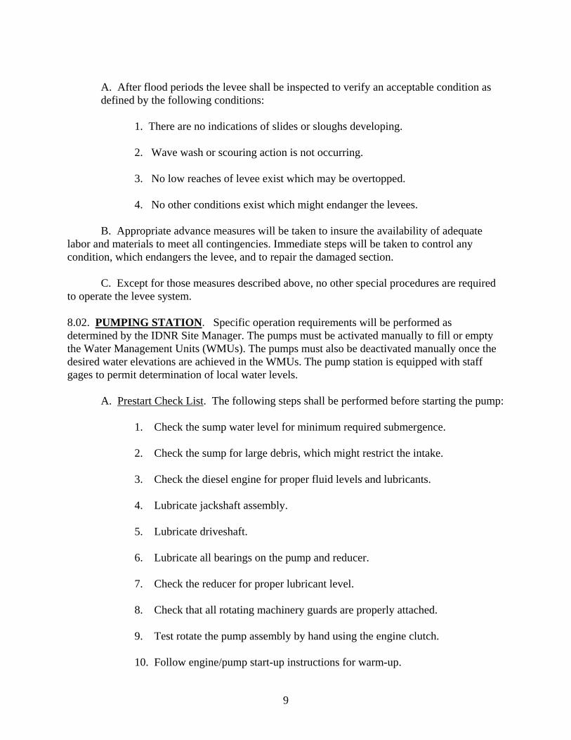
labor and materials to meet all contingencies. Immediate steps will be taken to control any condition, which endangers the levee, and to repair the damaged section. C. Except for those measures described above, no other special procedures are required to operate the levee system. 8.02. PUMPING STATION. Specific operation requirements will be performed as determined by the IDNR Site Manager. The pumps must be activated manually to fill or empty the Water Management Units (WMUs). The pumps must also be deactivated manually once the desired water elevations are achieved in the WMUs. The pump station is equipped with staff gages to permit determination of local water levels.
A. Prestart Check List. The following steps shall be performed before starting the pump: 1. Check the sump water level for minimum required submergence. 2. Check the sump for large debris, which might restrict the intake.
3. Check the diesel engine for proper fluid levels and lubricants.
4. Lubricate jackshaft assembly.
5. Lubricate driveshaft.
6. Lubricate all bearings on the pump and reducer.
7. Check the reducer for proper lubricant level.
8. Check that all rotating machinery guards are properly attached.
9. Test rotate the pump assembly by hand using the engine clutch.
10. Follow engine/pump start-up instructions for warm-up.
9

B. Normal Start-up. The following steps should be performed at system start-up:
1. Review engine operation instructions from the John Deere Series 500, 6101 OEM Diesel Engines Operator’s Manual, dated 26 Feb 93.
2. Start engine with clutch disengaged. 3. Allow engine to warm up at idle, as recommended in the Operator’s Manual.
4. Adjust engine speed to 800 revolutions per minute (rpm).
5. Partially engage clutch to observe for smooth operation, drive shaft alignment,
belt alignment, belt tension and any noisy operation. Repeat this step several times for brief periods to verify proper connection of prime driver to system.
6. After verification of connection, engage clutch fully at 800 rpm, then
gradually increase speed on the engine to normal operating speed of approximately 1800 rpm.
C. Normal Shutdown. The following steps should be performed at system shut-down:
1. Review engine operation instructions from the John Deere Series 500, 6101
OEM Diesel Engines Operator’s Manual, dated 26 Feb 93. 2. Gradually reduce engine speed to approximately 800 rpm. 3. Allow engine to run at 800 rpm for two to three minutes in order to empty
the pump discharge piping of water.
4. Disengage the clutch. (As the pump assembly comes to a stop, some water may backflow through the pump. This is normal, but the non-reverse ratchet on the gear drive should prevent reverse rotation of the pump impeller.)
5. Shut down the engine.
8.03. PUMPING STATION RETAINING WALL. Operation requirements for retaining walls shall be similar to the levee operation requirements in 8.01. (INSERT LOAD LIMITS ADJACENT TO WALLS – ED-DAS?) 8.04. DRAINAGE STRUCTURE. Specific operation requirements will be performed as determined by the IDNR Site Manager. The main source of water for the WMUs is Long Lake, which is connected to the Illinois River by the reversible pump station, as noted in 8.02, above. Drainage structure “A”, located at Long Lake interior levee #2, station 66+00, is operated to
10

manage the water level in Flat Lake at the lower end. Drainage structure “C”, located in the interior levee between Upper Stump Lake and Lower Stump Lake, is operated to manage the water level in Lower Stump Lake. When the WMUs are in use, or water level in the Illinois River rises with high sediment loads, drainage structure “E”, located in the southernmost portion of the exterior levee, should be closed to prevent sediment from entering the project. All operations procedures should be coordinated with the water management plan for the project (See Appendix G). Sluice gates should be at least one (1) inch from fully closed or fully open (using handcrank) before any use of the hydraulic operator. Never use the hydraulic operator to travel the final distance to closed or open. 8.05 STOPLOG STRUCTURES. Specific operation requirements will be performed as determined by the IDNR Site Manager. The main source of water for the WMUs is Long Lake, which is connected to the Illinois River by the reversible pump station, as noted in 8.02, above. Stop log structure “B”, located at Long Lake interior levee #5, station 13+15, is operated to manage the water level in Upper Stump Lake, as well as provide boat access. Stop log structure “D”, located in the interior levee #3 between Lower Stump Lake and Long Lake, is operated to manage the water level in Lower Stump Lake, as well as provide boat access. When the WMUs are in use, or water level in the Illinois River rises with high sediment loads, stop log structure “D” should be closed to prevent sediment from entering the project. All operations procedures should be coordinated with the water management plan for the project (See Appendix G). (INSERT LOAD LIMITS ADJACENT TO WALLS – ED-DAS? 8.06 FISH PASSAGE STRUCTURE. Specific operation requirements will be performed as determined by the IDNR Site Manager. The main source of water for the WMUs is Long Lake, which is connected to the Illinois River by the reversible pump station, as noted in 8.02, above. Fish passage structure “F”, located at exterior levee, station 70+50, is operated to manage the fish population in Long Lake. When the WMUs are in use, or water level in the Illinois River rises with high sediment loads, fish passage structure “F” should be closed to prevent sediment from entering the project. All operations procedures should be coordinated with the water management plan for the project (See Appendix G).
SECTION 9 PROJECT EMERGENCY OPERATIONS
The sponsor is responsible for the administration, operation, maintenance, and repair of the project in accordance with the existing MOA, the DPR, and this supplement. The sponsor shall maintain books, records, and accounting of all funds expended on the project within a mutually accepted accounting procedure. The sponsor shall incorporate reports and plans into its Annual Management Report / Plan all necessary information concerning the operation, maintenance and repair of the Project. The sponsor shall be required to fulfill operation, maintenance, repair and rehabilitation tasks as described for each feature of the project in Sections 6 through 12 of this manual. A reserve supply of materials needed to provide protection under flooding conditions, such as
11

sandbags, sand and emergency lighting, will be the responsibility of the local sponsor IDNR.
SECTION 10 PROJECT INSPECTION
10.01. GENERAL. . The sponsor and the USACE will conduct joint inspections of project facilities at least annually for the purpose of observing and reporting current condition of the facility and to determine the need for required repairs. The sponsor or the USACE will immediately notify the other party when a problem or potential problem of Project facilities is observed, and an additional joint inspection will be held. The sponsor shall request joint inspections of project facilities after specific storm or flood events for the purpose of agreement and determination of project rehabilitation 10.02. INSPECTION PURPOSE. An active preventative maintenance program reduces damage to constructed features by taking early corrective action. Additional costs, associated with repair and rehabilitation, are also avoided. An effective preventative maintenance program requires regular, thorough inspections. These inspections will aid the IDNR Site Manager in discovering deficiencies within the project. In addition, they will provide the IDNR Site Manager with baseline condition data. These data are necessary for considering repair options of major damage. 10.03. TYPE OF INSPECTIONS. The two types of inspections for the Stump Lake project are project inspections, conducted by the IDNR Site Manager, and joint inspections, conducted by the IDNR Site Manager together with personnel from USACE and USFWS. 10.04. ANNUAL PROJECT INSPECTIONS. Annual project inspections shall be performed by the IDNR Site Manager, or appropriate representative, for the purpose of noting routine deficiencies and initiating corrective actions. This inspection shall be conducted at periods not exceeding 12 months and shall follow inspection guidance presented in subsequent sections of this manual. It is suggested that the inspection be conducted every Spring or Fall, whichever is representative of site conditions following high river levels. Additional project inspections shall occur as necessary after flood events or as scheduled by the IDNR Site Manager. A project inspection checklist has been developed as presented in Appendix D. It is required that the IDNR Site Manager furnish a signed copy of the completed checklist to the U.S. Army Corps of Engineers; St. Louis District; ATTN: CEMVS-ED; 1222 Spruce Street; St. Louis, Missouri, 63103, immediately following each project inspection.
10.05. JOINT INSPECTIONS. Joint inspections by the IDNR Site Manager, USFWS, and USACE shall be completed in accordance with the Memorandum of Agreement. These inspections shall be initiated by USACE. The purpose of joint inspections is to assure that adequate maintenance is being performed as presented in this manual. The St. Louis District Engineer or Authorized Representative shall have access to all portions of the constructed project upon coordination with the IDNR Site Manager. Additional joint inspections shall be formally requested by the IDNR Site Manager immediately
12

following a specific storm or flood event that causes damage in excess of the annual operation and maintenance costs specified in this manual. A comparison of project inspections before and after such events together with the joint inspections shall be the basis for determining maintenance responsibility and potential rehabilitation by USACE as stated in the Memorandum of Agreement.
SECTION 11 PROJECT MAINTENANCE
The sponsor is responsible for the administration, operation, maintenance, and repair of the project in accordance with the existing MOA, the DPR, and this supplement. The sponsor shall maintain books, records, and accounting of all funds expended on the project within a mutually accepted accounting procedure. The sponsor shall incorporate reports and plans into its Annual Management Report / Plan all necessary information concerning the operation, maintenance and repair of the Project. The sponsor shall be required to fulfill operation, maintenance, repair and rehabilitation tasks as described for each feature of the project in Sections 6 through 12 of this manual. 11.01. PROJECT LEVEES. Maintenance requirements for the Riverside (Exterior) Levee and the Interior Levees are as follows:
A. General Requirements. IDNR shall provide at all times such maintenance as may be required to insure serviceability of the structures. Measures shall be taken to promote the growth of sod, exterminate burrowing animals, and to provide for routine mowing of the grass and weeds, removal of wild growth and drift deposits, and repair of damage caused by erosion or other forces. Where practicable, measures shall be taken to retard bank erosion by planting of willows or other suitable growth on areas riverward of the levees. Periodic inspections shall be made by IDNR to insure that the above maintenance measures are being effectively carried out and further, to be certain that:
1. No unusual settlement, sloughing, or material loss of grade or levee cross
section has taken place. 2. No caving has occurred on either the land side or the river side of the levee,
which might affect the stability of the levee section.
3. No seepage, saturated areas, or sand boils are occurring. 4. Drains through the levees and gates on said drains are in good working
condition.
5. No revetment work or riprap has been displaced, washed out, or removed.
6. No action is being taken, such as burning grass and weeds during inappropriate seasons, which will retard or destroy the growth of sod.
13
7. Access roads to and on the levee are being properly maintained.
8. Cattle guards and gates are in good condition.
9. Crown of levee is shaped so as to drain readily, and roadway thereon, if any,
is well shaped and maintained.
10. There is no unauthorized grazing or vehicular traffic on the levees.
11. Encroachments are not being made on the levee right-of-way, which might endanger the structure or hinder its proper and efficient functioning dining times of emergency.
B. Detailed Requirements. In addition to the general requirements described above additional detailed maintenance requirements for levee works are as follows: 1. General. It is the responsibility of the sponsor to maintain the integrity of stone protection works and also the vegetated areas that provide stability to levee slopes. Inspections to detect erosion, scour, tension cracks and sinkholes at or adjacent to the protected areas shall be conducted on a regular basis. Visual observances of flaws or defects shall be clearly documented and photographed. Erosion and scour can cause losses of earthen material and may potentially jeopardize the stone protection. If there is severe weathering of some materials in the stone protected areas, additional stone shall be placed to cover these materials and to prevent additional losses of stone protection. Pockets of rearranged or missing stone should be filled with materials similar in size and quality to that provided under the contract documents. It is extremely important to observe the termination points of the stone placement. Inspections of the stone protection work shall be made at least once every 90 days, preferably during the dry periods when the water level is low. 2. Mowing. Levee slopes shall be mowed periodically to discourage the growth of weeds and saplings. A good mowing program will enhance a dense sod that will resist wave wash and erosion during periods of high water. Grass should be kept at a height less than 14 inches. The grass should be cut back to a height of approximately 4 to 6 inches during the growing season; it may be necessary to mow at least two or three times each year to maintain a stand of grass within these prescribed limits. The height of the grass should be at least 8 inches when it becomes dormant prior to winter. 3. Herbicides. Mowing should be supplemented by the periodic use of environmentally acceptable herbicides to discourage the growth of weeds and brush. All riprap areas along the levee slope shall be sprayed once in the spring and once in the fall with “Rodeo” (by Roundup) or equal to eradicate weeds and woody growth. 4. Treatment of Sprouts. The stumps of trees cleared from the levees should be treated by spraying with herbicides to eliminate the growth of sprouts.
14
5. Rodent and Burrowing Animals. Rodent dens can undermine and potentially damage the levees. Rodents and burrowing animals should be destroyed during inspections and their dens excavated and backfilled with compacted fill. Routine mowing of the levee slopes and chemical control of weeds and woody growth should discourage rodents and burrowing animals from establishing dens in the earth levees. Various other methods are available for removal of rodents and burrowing animals. However, the best methods of removing rodents and burrowing animals from the levee system will be developed by experimentation. Care should be used to determine local game laws and their applicability to the method chosen for extermination. Following are several methods of extermination that have proven satisfactory. Suggested methods are:
a. Fish and wildlife cartridge. b. Cyanide gas.
c. Exhaust fumes (carbon monoxide).
d. Butane or propane gas.
e. Anhydrous ammonia.
6. Woody Growth. It is necessary to remove trees, brush, and other woody growth from levees slopes in order to maintain the long-term integrity of the levee structure. The periodic removal of this growth is far more economical than extensive tree removal that may be necessary if these saplings are not removed at an early stage. 7. Earth-lined Channel Inspection. During periodic inspection of the levees careful attention should be given to the following items:
a. No unusual settlement, sloughing, or material loss of grade or levee cross section has taken place.
b. No caving has occurred within or adjacent to the levee, which might
affect the stability of the levee section.
c. No revetment work or riprap has been displaced, washed out, or removed.
d. No action is being taken, such as burning grass and weeds, which will
retard the growth of sod.
e. No wave wash or scouring has occurred.
f. Drift shall be removed from levee slopes at the end of each winter flood season, before the new growth of grass starts in the spring, and after each high water event occurring during the growing season. Drift should not be burned on the levee slope or right-of way.
15
g. Gullies, holes and washes in the levee should be filled with materials
matching that required by the original contract documents, including all amendments and modifications thereto.
8. Seeding. Reseeding of damaged areas, mulching, fertilizing, and preparation, shall be accomplished with seed mixtures, mulch, fertilizer, and rates and methods of application matching that required in the original contract documents for the particular area requiring repair. Seeding periods are as follows:
a. Fall Seeding: 15 August to 20 September b. Spring Seeding: 15 February to 15 April
c. Repair and Preparation of Seedbed. Repairs required to correct conditions disclosed by the inspection should be made promptly, especially during non-flood season, in anticipation that high water may retard or prevent later accomplishment. In the event of severe damage a report should be made to the District Engineer, U. S. Army Engineer District, 1222 Spruce Street, St. Louis, Missouri 63103, including a description of the damage and proposed repair action. The channel slopes should be dressed so that they may be traveled with mowing equipment. Prior to mulching, the area to be seeded should be disked or harrowed to loosen the soil.
d. Touchup or Overseeding. Where the stand of grass is thin, the growth shall be thickened by overseeding with grass seed. This should be done in late winter or early spring between 15 February and 15 April, preferably in the early part of the period.
e. Fertilizing. If the soil is suspected of containing insufficient nutrients to provide proper growth, a laboratory analysis shall be performed. Fertilization shall be performed only as a result of such an analysis. At the time of seeding, apply 33% ammonium nitrate fertilizer, or an equivalent thereof, in such quantity to yield 50 pounds of nitrogen per acre. In the case of 33% ammonium nitrate, 150 pounds of fertilizer per acre will be required. Fertilizer should be applied by drill, or broadcast uniformly on the area. The fertilizer should be disked or harrowed into the soil. f. Supplemental Fertilizing. A thick, healthy stand of grass furnishes protection to the channel against surface erosion, and so minimizes the amount of possible repair needed. It is recommended that a feeder application of fertilizer consisting of 12/12/12 mixture be applied about every third year at a rate of 100 to 200 pounds per acre. Soil sampling is recommended which will indicate the proper mixture required and may reduce the rate and cost of application. 11.02. PUMPING STATION. Maintenance requirements for the Pumping Station are described in the Couch Pump Company “Installation, Operation & Maintenance Manual” for serial numbers 6933 and 6934, dated 3-2-95, and the John Deere Series 500, 6101 OEM Diesel Engines Operator’s Manual, dated 26 Feb 93. Annual periodic inspections will be performed to
16

assess the operating condition of the pumps, gear reducers, engine and appurtenances. Annual inspections should be scheduled for an occasion where the pumps may be operated with sufficient water available for proper demonstration of pumping. A. Concrete Structure. All visible concrete surfaces should be inspected for cracks, spalling, corrosion, or exposed reinforcement. All structural steel items should be inspected for warpage, damage, corrosion or lost fasteners. Repairs shall be made within 30 days of discovery, including grouting, coating repair, epoxy repairs and fastener replacement.
B. Pump Assembly. The pump assembly consists of the pump, the reducer, the drive belts, the jackshaft assembly, the driveshaft, the diesel engine assembly, the Dresser coupling, discharge pipe, flap gate, the support piles and appurtenances. The pump assembly should be inspected during operation for any improper vibration, noise, excessive heat, sump vortices, or cavitation. Operation during ice conditions should be avoided. The pump should be throttled down and shut off when cavitation is detected, until the cause can be determined and corrected. Any serious damage should be reported immediately to USACE and USFWS for determination of corrective action. Simple repairs, such as painting and repair of fasteners, should be performed by IDNR prior to any pump operation. 1. Sump. The sump should be checked periodically for excessive siltation and proper suction head. The sump should be cleaned periodically to prevent cavitation. All large debris should be removed from the sump area for proper disposal. The pile supports should be inspected for damage and corrosion during any cleaning or inspection of the sump.
2. Pile Supports. The “H”-pile pump supports should be inspected annually, and prior to any operation, for cracks, dents, bending, twisting and corrosion.
3. Dresser Coupling. The Dresser coupling should be inspected annually, and
prior to any operation, for damage to any flanges, middle ring, gaskets, fasteners or pipe. Loose fasteners should be tightened prior to operation. Corroded fasteners should be replaced prior to operation. After commencement of operation the coupling should be inspected for excessive vibration or leakage.
4. Flap Gate. The flap gate, located on the discharge end of the discharge
pipe, should be inspected and lubricated annually. The flap gate hinges should be lubricated prior to any pump operation.
5. Right Angle Reducer. The gear reducer should be inspected for proper lubricant level prior to each operation. Sufficient lubricant to meet the manufacturer’s recommendations should be added prior to each operation. After the engine has reached normal speed, and for at least fifteen (15) minutes of subsequent pump operation, the reducer should be checked for excessive noise, vibration or temperature
6. Drive Belts and Pulleys. The drive belts and pulleys should be inspected annually, and prior to any operation, for cracks, wear, bending, twisting, sagging, slack and corrosion. Cracked or worn belts should be replaced prior to any operation. Corroded pulleys
17

should be cleaned and painted. Any slack, sag or twisting of the belts from their normal orientation should be corrected prior to operation.
7. Jackshaft Assembly. The jackshaft assembly should be inspected annually,
and prior to any operation, for cracks, bending, twisting, sagging, lubricant and corrosion. The pillow block bearings should be lubricated prior to any operation.
8. Driveshaft. The driveshaft should be inspected annually, and prior to any
operation, for bending, twisting, sagging, loose fasteners and corrosion. The universal joints should be lubricated prior to any operation.
C. Diesel Engine. The diesel engine should be inspected annually, and prior to any operation, for proper fluid levels, lubrication, coolant, air filter, fuel filter, battery and muffler. The engine trailer should be inspected for proper lubrication of spindles, operation of brakes, operation of signal lights, operation of hitch and safety chain, and damage to paint coating. All fluids and filters should be at the proper operating levels and conditions prior to transport to the pumping station. The engine should be operated prior to transport to the pumping station to establish operational worthiness, including function of the clutch and instrumentation. After connection to the driveshaft, the engine should be operated as indicated in 8.02 A, above. The operator should record oil pressure, coolant temperature, charging amperage, revolutions per minute (rpm), and hours of operation. This data will be used to assess the condition of engine over time. 11.03. PUMPING STATION RETAINING WALLS. Maintenance requirements for the retaining walls should be as follows: A. Sheet Pile. The aboveground sheet pile should be inspected annually during low water stages for corrosion, perforation, bulging and any other damage. Any serious damage should be reported immediately to USACE and USFWS for determination of corrective action. B. Tie-Rods. The tie-rod connections at the wales should be inspected annually for loose fasteners, corrosion, weld cracks and any other damage. Any serious damage should be reported immediately to USACE and USFWS for determination of corrective action. Simple repairs, such as painting and repair of fasteners, should be performed by IDNR prior to any pump operation. C. Discharge Pipe Penetrations. The discharge pipe penetrations should be inspected for loss of material or geotextile at the 3-inch annular space between pipe and sheet pile. Discharge pipe, including flap gates, should be inspected for corrosion or any other damage. Any serious damage should be reported immediately to USACE and USFWS for determination of corrective action. Simple repairs, such as painting and repair of fasteners, should be performed by IDNR prior to any pump operation. 11.04. DRAINAGE STRUCTURES. Maintenance requirements for the drainage structures are described herein, and as noted in the Waterman Industries, Inc. Operation and Maintenance Manual for Sluice and Canal Gates. Annual periodic inspections will be performed to assess the operating condition of the gates, operators, access ladders, corrugated metal pipe (CMP) and
18

appurtenances. Annual inspections should be scheduled for low water occasions where the maximum extent of the equipment will be accessible. Any serious damage should be reported immediately to USACE and USFWS for determination of corrective action. Simple repairs, such as painting and repair of fasteners, should be performed by IDNR prior to any operation. A. Sluice Gate. Periodic cleaning is required to maintain smooth operation. Periodic painting should be performed to minimize corrosion. All adjustments to the wedges, as required by wear, should be in accord with operation and maintenance manual. The gates should be cycled regularly to alleviate “sticking”. Cycling at minimum thirty (30) day intervals is recommended. B. Operating Stem. The operating stem should be cleaned and greased with Mobilux grease # 2EP, or equal, at least every six (6) months.
C. Gate Operator. The gate operator should be lubricated prior to each new period of operation, but not less than 4 times annually. The handcrank should be turning when grease is pumped into the fittings. Each fitting should receive the amount of grease delivered by 4-5 pumps of the grease gun handle.
D. Hydraulic Power Unit. The hydraulic power unit should be prepared for use as indicated by the manufacturer prior to each use in the field. Check all fluid levels and fill to appropriate level. Check all hoses, motor, pump, directional control valve, etc. for leaks. Tighten leaking connections, or replace parts as required. E. Field Service by Manufacturer. If proper performance cannot be obtained, using the existing operations and maintenance manual procedures, contact: Waterman Industries, Inc., P.O. Box 458, Exeter, CA 93221, (209) 562-4000. Use job number B-5992, for reference, to expedite service requests. 11.05. STOP LOG STRUCTURES. Maintenance requirements for the stop log structures are described herein, and in the operation and maintenance manual for the jib crane / trolley hoist. Annual periodic inspections will be performed to assess the operating condition of the stop logs, concrete structure, jib crane, trolley hoist and appurtenances. Annual inspections should be scheduled for low water occasions where the maximum extent of the equipment will be accessible. Any serious damage should be reported immediately to USACE and USFWS for determination of corrective action. Simple repairs, such as painting and repair of fasteners, should be performed by IDNR prior to any operation. A. Stop Log. All stop logs should be inspected for warpage, cracks, deformities or other damage, which would prevent proper installation or sealing prior to each use. Damaged stop logs should be replaced before installation. B. Concrete Structure. All visible concrete surfaces should be inspected for cracks, spalling, corrosion, or exposed reinforcement prior to each use.
C. Jib Crane. The jib crane should be inspected prior to each new period of operation.
19

All structural steel items should be inspected for warpage, damage, corrosion or lost fasteners. Repairs should be made within 30 days of discovery, including any grouting, coating repair and fastener replacement. Parts or service for the jib crane are available from Gaffey Crane, Houston, TX, 1-800-233-8179, using the model number 4631HH to identify the specific order for this project. 11.06. FISH PASSAGE STRUCTURE. Maintenance requirements for the fish passage structure are described herein, and as noted in the Waterman Industries, Inc. Operation and Maintenance Manual for Sluice and Canal Gates. Annual periodic inspections will be performed to assess the operating condition of the gates, operators, concrete, stop logs, structural steel and appurtenances. Annual inspections should be scheduled for low water occasions where the maximum extent of the equipment will be accessible. Any serious damage should be reported immediately to USACE and USFWS for determination of corrective action. Simple repairs, such as painting and repair of fasteners, should be performed by IDNR prior to any operation. A. Sluice Gate. Periodic cleaning is required to maintain smooth operation. Periodic painting should be performed to minimize corrosion. All adjustments to the wedges, as required by wear, should be in accord with operation and maintenance manual. The gates should be cycled regularly to alleviate “sticking”. Cycling at minimum thirty (30) day intervals is recommended. B. Operating Stem. The operating stem should be cleaned and greased with Mobilux grease # 2EP, or equal, at least every six (6) months.
C. Gate Operator. The gate operator should be lubricated prior to each new period of operation, but not less than 4 times annually. The handcrank should be turning when grease is pumped into the fittings. Each fitting should receive the amount of grease delivered by 4-5 pumps of the grease gun handle.
D. Hydraulic Power Unit. The hydraulic power unit should be prepared for use as indicated by the manufacturer prior to each use in the field. Check all fluid levels and fill to appropriate level. Check all hoses, motor, pump, directional control valve, etc. for leaks. Tighten leaking connections, or replace parts as required. E. Field Service by Manufacturer. If proper performance cannot be obtained, using the existing operations and maintenance manual procedures, contact: Waterman Industries, Inc., P.O. Box 458, Exeter, CA 93221, (209) 562-4000. Use job number B-5992, for reference, to expedite service requests. F. Stop Log. All stop logs should be inspected for warpage, cracks, deformities or other damage, which would prevent proper installation or sealing prior to each use. Damaged stop logs should be replaced before installation. G. Concrete Structure. All visible concrete surfaces should be inspected for cracks, spalling, corrosion, or exposed reinforcement prior to each use.
20
11.07. MISCELLANEOUS EQUIPMENT. Miscellaneous items, such as fencing and guardrail, should be maintained free from corrosion and physical damage. These items should be replaced when they are no longer able to properly serve their design function.
SECTION 12 PROJECT REPAIR, REPLACEMENT AND REHABILITATION
12.01. GENERAL. The sponsor is responsible for the administration, operation, maintenance, and repair of the project in accordance with the existing MOA, the DPR, and this supplement. The sponsor shall maintain books, records, and accounting of all funds expended on the project within a mutually accepted accounting procedure. The sponsor shall incorporate reports and plans into its Annual Management Report / Plan all necessary information concerning the operation, maintenance and repair of the Project. The sponsor shall be required to fulfill operation, maintenance, repair and rehabilitation tasks as described for each feature of the project in Sections 6 through 12 of this manual. Repair is considered to entail those activities of a routine nature that maintain the project in a well-kept condition. Replacement covers those measures taken when a worn-out element, or portion thereof, is replaced. Rehabilitation refers to a set of activities necessary to bring a deteriorated project back to its original condition. Project repair, replacement and rehabilitation actions are to conform to the project as-built plans and specifications, unless other arrangements are made with the USACE, St. Louis District, Commander. These activities are the responsibility of the project sponsor. 12.02. REHABILITATION REQUIREMENTS. The USACE is responsible for the federal share and the performance of any mutually agreed upon rehabilitation of the project in accordance with the existing Memorandum of Agreement, the DPR and this supplement. The federal share of rehabilitation is defined to be reconstructive work needed in excess of estimated annual operation, maintenance and repair costs as a result of specific storm or flood events, exceeding the design event. 12.03. IMPROVEMENTS, REPAIRS OR ALTERATIONS. The USACE, St. Louis District, Commander shall be informed of all future improvements, repairs or alterations to this environmental enhancement project. Any portions of the existing levee works damaged by flood waters shall be repaired to the original condition in accordance with the requirements of the contract documents, including all amendments and modifications thereto. 12.04. PROJECT FEATURE REPLACEMENT. If a project feature, such as an area of levee, riprap revetment, pumping station, or structure, is damaged to the point where it needs to be completely replaced, the sponsor shall coordinate with the USACE, St. Louis District, Commander about the planned replacement. In general, the replacement feature should conform to the original design of that feature. 12.05. PROJECT FEATURE ALTERATION. Whenever it is necessary to alter project features that have been constructed with Federal funds, or rehabilitated with Federal funds, for which operation and maintenance assurances have been executed by IDNR, it is necessary to secure prior approval from the USACE, St. Louis District, Commander. When a third party, such
21

as a utility or pipeline company, desires to alter the levee work, they must secure approval from IDNR, who, in turn, will secure approval from the USACE, St. Louis District, Commander. All matters pertaining to “Alterations” should be addressed to the USACE, St. Louis District, Commander.
SECTION 13 NOTIFICATION OF PROJECT DISTRESS
13.01. GENERAL. Evidence of distress at the Stump Lake Project shall be immediately reported to the District Commander, USACE, St. Louis District. Notification shall be in writing. Special inspections, to evaluate damages or changed conditions, should be made immediately following the report of project distress. This is particularly important in the case of earthquake damage. 13.02. REPORTABLE DISTRESS SIGNALS. Typical signals of project distress to be reported are as follows: A. Sloughs, settlement, or slides in embankments, such as levees, dams, bridge abutments or slopes of channels. B. Evidence of piping or muddy water boils in the vicinity of a structure such as embankments, abutments, and retaining walls. C. Abnormal increase or decrease of flow from foundation drains, structural joints, or face drains of concrete dams. D. Any increase in seepage quantities through or under embankments or abutments. E. Unusual vertical or horizontal movement or cracking of embankments, abutments or structures. F. Significant cracking of mass concrete structures. G. Sinkholes or localized subsidence in the foundation of, or adjacent to, embankments or other pertinent structures critical to the safe operation of the project. H. Excessive deflection, displacement, or vibration of concrete structures (e.g., tilting or sliding of structure). I. Erratic movement, binding, excessive deflection, or vibration of outlet gates, stop logs, or pump mounting piles. J. Significant damage to any structure.
22
K. Significant damage to any feature resultant from a seismic event. L. Any other indications of distress or potential failure that could inhibit the operation of the project or endanger life and property. M. Excessive vibration, binding, unusual noises, movements, or deflections of gate hoist operating equipment. N. Actual hydraulic equipment operating pressure in excess of 125 percent of the normal operating pressure. Electric motor operating equipment overheating or stalling. O. Erratic movement or unusual sounds such as bumping, jumping, or popping of mechanical equipment and appurtenances. P. Wire rope lifting cables, chains, etc. having broken, deformed, worn or corroded elements. Q. Frequent power interruptions. R. Failure of major mechanical or electrical equipment.
23

APPENDIX A
MEMORANDUM OF AGREEMENT BETWEEN
THE UNITED STATES FISH AND WILDLIFE SERVICE AND
THE DEPARTMENT OF THE ARMY FOR
ENHANCING FISH AND WILDLIFE RESOURCES OF THE
UPPER MISSISSIPPI RIVER SYSTEM AT
STUMP LAKE COMPLEX HABITAT REHABILITATION AND ENHANCEMENT PROJECT
JERSEY COUNTY, ILLINOIS
I. PURPOSE The purpose of this Memorandum of Agreement (MOA) is to establish the relationships, arrangements, and general procedures under which the U.S. Fish and Wildlife Service (USFWS) and the Department of the Army (DA) will operate in constructing, operating, maintaining, repairing, and rehabilitating the Stump Lake Complex Habitat Rehabilitation and Enhancement Project (HREP), Illinois, separable element of the Upper Mississippi River System-Environmental Management Program (UMRS-EMP). II. BACKGROUND a. The project lands of the Stump Lake Complex HREP are managed under a cooperative agreement between the Department of the Interior, USFWS, and the U.S. Army Corps of Engineers, dated 14 February 1963. Management of these project lands has been assumed by the Illinois Department of Natural Resources (IDNR) under a cooperative agreement between the USFWS and the IDNR. b. Section 1103 of the Water Resources Development Act (WRDA) of 1986, Public Law 99-662, authorizes construction of measures for the purpose of enhancing fish and wildlife resources in the Upper Mississippi River System. Under conditions of Section 906(e) of WRDA 1986, Public Law 99-662, all construction costs of those fish and wildlife features for the Stump Lake Complex HREP are 100 percent Federal, and pursuant to Section 107(b) of WRDA 1992, Public Law 102-580, all costs of operation and maintenance for the Stump Lake Complex HREP are 100 percent non-federal. III. GENERAL SCOPE
24

The project to be accomplished pursuant to this MOA shall consist of complex wetlands managed primarily for migratory waterfowl habitat. Moist soil and aquatic vegetation management techniques shall be employed by manipulating water levels of the five wetland units in the complex. IV. RESPONSIBILITIES a. DA is responsible for: 1. Construction. Constructing a low sediment deflection levee 5.5 miles long paralleling the Illinois River shoreline and the perimeter of the Stump Lake waterfowl management area, constructing seven low-level interior levees around the perimeters of the four main wetland compartments, installing sluice gates and stoplog structures, and constructing a reversible pumping system. 2. Major Rehabilitation. The Federal share of any mutually agreed upon rehabilitation of the project that exceeds the annual operation and maintenance requirements identified in the Definite Project Report and that is needed as a result of specific storm or flood events. 3. Construction Management. Subject to and using funds appropriated by the Congress of the United States, and in accordance with Section 906(e) of the WRDA 1986, Public Law 99-662, DA will construct the Habitat Rehabilitation and Enhancement Project of the Stump Lake Complex, Illinois, as described in the UMRS-EMP Definite Project Report with Integrated Environmental Assessment dated January 1992, applying those procedures usually followed or applied in Federal projects, pursuant to Federal laws, regulations, and policies. The USFWS will be afforded the opportunity to review and comment on all modifications and change orders prior to the issuance to the contractor of a Notice to Proceed. If DA encounters potential delays related to construction of the project, DA will promptly notify USFWS of such delays. 4. Maintenance of Records. The DA will keep books, records, documents, and other evidence pertaining to costs and expenses incurred in connection with construction of the project to the extent and in such detail as will properly reflect total costs. The DA shall maintain such books, records, documents, and other evidence for a minimum of three years after completion of construction of the project and resolution of all relevant claims arising therefrom, and shall make available at its offices, at reasonable times, such books, records, documents, and other evidence for inspection and audit by authorized representatives of the USFWS. b. USFWS Responsibilities. Upon completion of construction as determined by the District Engineer, St. Louis, the USFWS shall accept the Project as part of the Mark Twain National Wildlife Refuge of the Stump Lake Complex HREP, Illinois.
25

c. Non-Federal Responsibilities. In accordance with Section 107(b) of WRDA 1992, Public Law 102-580, 100 percent of all costs associated with the operation, maintenance, and repair of the Stump Lake Complex HREP, Illinois, will be borne by the USFWS and IDNR. V. MODIFICATION AND TERMINATION This MOA may be modified or terminated at any time by mutual agreement of the parties. Any such modification or termination must be in writing. Unless otherwise modified or terminated, this MOA shall remain in effect for a period of no more than 50 years after initiation of construction of the project. VI. REPRESENTATIVES The following individuals or their designated representatives shall have authority to act under this MOA for their respective parties: USFWS: Regional Director U.S. Fish and Wildlife Service Federal Building, 1 Federal Drive Fort Snelling, MN 55111-4056 DA: District Engineer U.S. Army Engineer District, St. Louis 1222 Spruce Street St. Louis, MO 63103-2833 VII. EFFECTIVE DATE OF MOA This MOA shall become effective when signed by the appropriate representatives of both parties. DEPARTMENT OF THE ARMY U.S. FISH AND WILDLIFE SERVICE BY: _________________________ BY: _____________________________ C. KEVIN WILLIAMS ROBYN THORSON Colonel, U.S. Army Regional Director District Engineer U.S. Fish and Wildlife Service DATE: _______________________ DATE: __________________________
26

APPENDIX B GENERAL PROJECT DRAWINGS
Plate E-1, Drawing M-EMP 0/2, Location and Vicinity Map Plate E-2, Drawing M-EMP 1/2, General Site Plan Plate E-3, Drawing M-EMP 62/1, Drainage Structure A Plans and Sections Plate E-4, Drawing M- EMP 62/2, Drainage Structure C Plans and Sections Plate E-5, Drawing M- EMP 62/3, Drainage Structure E Plans and Sections Plate E-6, Drawing M- EMP 62/7, Stop Log Structures Site “B” & “D” Plate E-7, Drawing M- EMP 62/8, Fish Passage Structure, Site “F” Plate E-8, Drawing M- EMP 88/1, Boat Ramp Plate E-9, Drawing M- EMP 88/2, Boat Ramp Profile and Sections Plate E-10, Drawing M- EMP 91/1, Pump Station Plan and Profiles Plate E-11, Drawing M- EMP 91/2, Pump Station Details Plate E-12, Drawing M- EMP 91/3, Illinois River Retaining Wall Plate E-13, Drawing M- EMP 91/4, Long Lake Retaining Walls Plate E-14, Drawing M- EMP 91/5, Cofferdam Plan and Section Illinois River Pump Note: The above drawings are of principle interest for OMRR&R purposes. Complete "As-Advertised" drawings and complete "As-Built" drawing files are located on the CD furnished as part of this manual. Hard copies of the drawings are not provided but may be printed from the CD.
27

APPENDIX C CONSTRUCTION DRAWINGS
Note: All "As-Advertised" drawings and complete "As-Built" drawing files are located on the CD furnished as part of this manual. Hard copies of the drawings are not provided but may be printed from the CD.
28

APPENDIX D PROJECT INSPECTION CHECKLIST
29

30

31

32

APPENDIX E FINDING OF NO SIGNIFICANT IMPACT (FONSI)
33

APPENDIX F ACRONYMS
CMP - Corrugated Metal Pipe DA - Department of the Army DPR - Definite Project Report FONSI - Finding of No Significant Impact GP - General Plan HREP – Habitat Rehabilitation and Enhancement Project IDNR - Illinois Department of Natural Resources MOA - Memorandum of Agreement NEPA - National Environmental Policy Act NGVD - National Geodetical Vertical Datum OEM - Original Equipment Manufacturer UMRS-EMP - Upper Mississippi River System – Environmental Management Plan USACE - United States Army Corps of Engineers USFWS - United States Fish and Wildlife Service WMU - Water Management Unit WRDA - Water Resources Development Act
34