Manual for new External Camera Workflow - HDSscansw.leica-geosystems.com/public/camera/data for new...
27
Cyclone External Camera Workflow-Nodal Ninja bracket High-Definition Surveying Version 1 Leica Geosystems HDS
Transcript of Manual for new External Camera Workflow - HDSscansw.leica-geosystems.com/public/camera/data for new...
Cyclone External Camera Workflow-Nodal Ninja bracket
High-Definition Surveying
Version 1
Leica Geosystems HDS
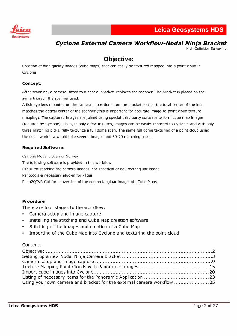
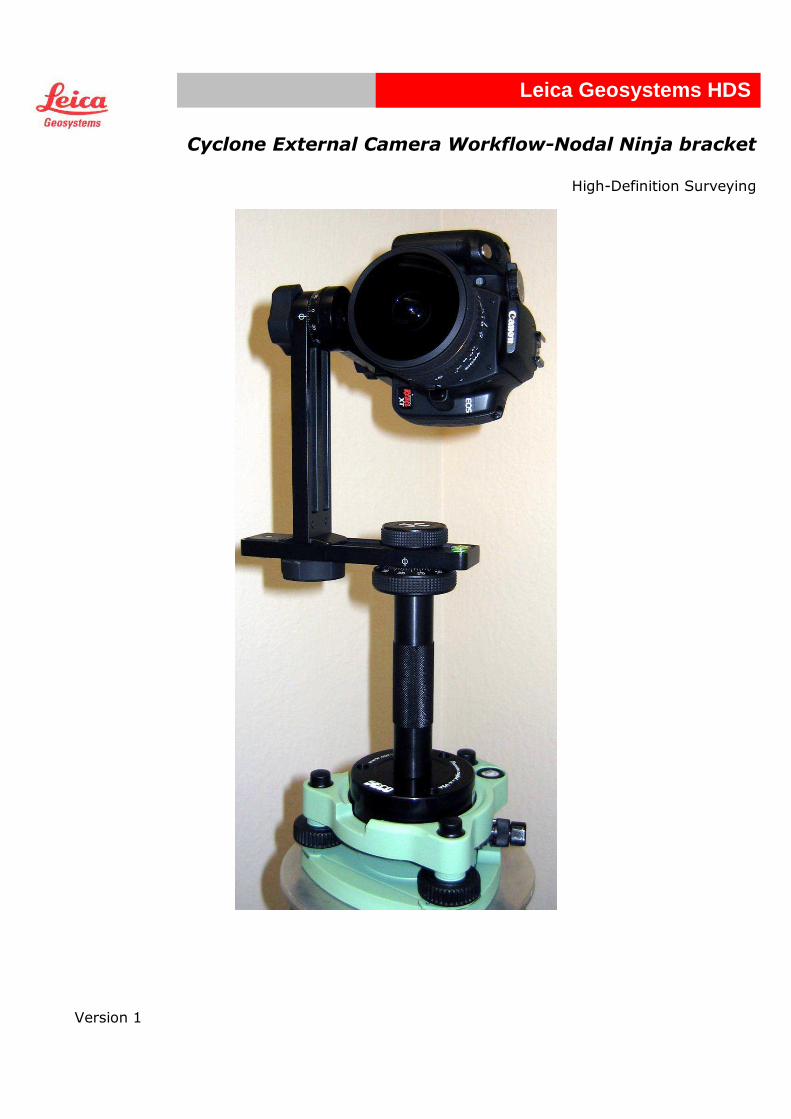
Cyclone External Camera Workflow-Nodal Ninja Bracket
High-Definition Surveying
Leica Geosystems HDS Page 2 of 27
Leica Geosystems HDS
Objective: Creation of high quality images (cube maps) that can easily be textured mapped into a point cloud in
Cyclone
Concept: After scanning, a camera, fitted to a special bracket, replaces the scanner. The bracket is placed on the
same tribrach the scanner used.
A fish eye lens mounted on the camera is positioned on the bracket so that the focal center of the lens
matches the optical center of the scanner (this is important for accurate image-to-point cloud texture
mapping). The captured images are joined using special third party software to form cube map images
(required by Cyclone). Then, in only a few minutes, images can be easily imported to Cyclone, and with only
three matching picks, fully texturize a full dome scan. The same full dome texturing of a point cloud using
the usual workflow would take several images and 50-70 matching picks.
Required Software: Cyclone Model , Scan or Survey
The following software is provided in this workflow:
PTgui-for stitching the camera images into spherical or equirectangluar image
Panotools-a necessary plug-in for PTgui
Pano2QTVR Gui-for conversion of the equirectangluar image into Cube Maps
Procedure
There are four stages to the workflow:
• Camera setup and image capture
• Installing the stitching and Cube Map creation software
• Stitching of the images and creation of a Cube Map
• Importing of the Cube Map into Cyclone and texturing the point cloud
Contents
Objective: ......................................................................................................... 2
Setting up a new Nodal Ninja Camera bracket ......................................................... 3
Camera setup and image capture .......................................................................... 9
Texture Mapping Point Clouds with Panoramic Images ............................................ 15
Import cube images into Cyclone ......................................................................... 20
Listing of necessary items for the Panoramic Application ......................................... 23
Using your own camera and bracket for the external camera workflow ...................... 25
Cyclone External Camera Workflow-Nodal Ninja Bracket
High-Definition Surveying
Leica Geosystems HDS Page 3 of 27
Leica Geosystems HDS
Setting up a new Nodal Ninja Camera bracket If you have just purchased a Nodal Ninja bracket, please follow these setup instructions before proceeding to the next section.
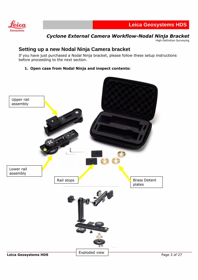
1. Open case from Nodal Ninja and inspect contents:
Upper rail assembly
Brass Detent plates
Lower rail assembly
Rail stops
Exploded view
Cyclone External Camera Workflow-Nodal Ninja Bracket
High-Definition Surveying
Leica Geosystems HDS Page 4 of 27
Leica Geosystems HDS
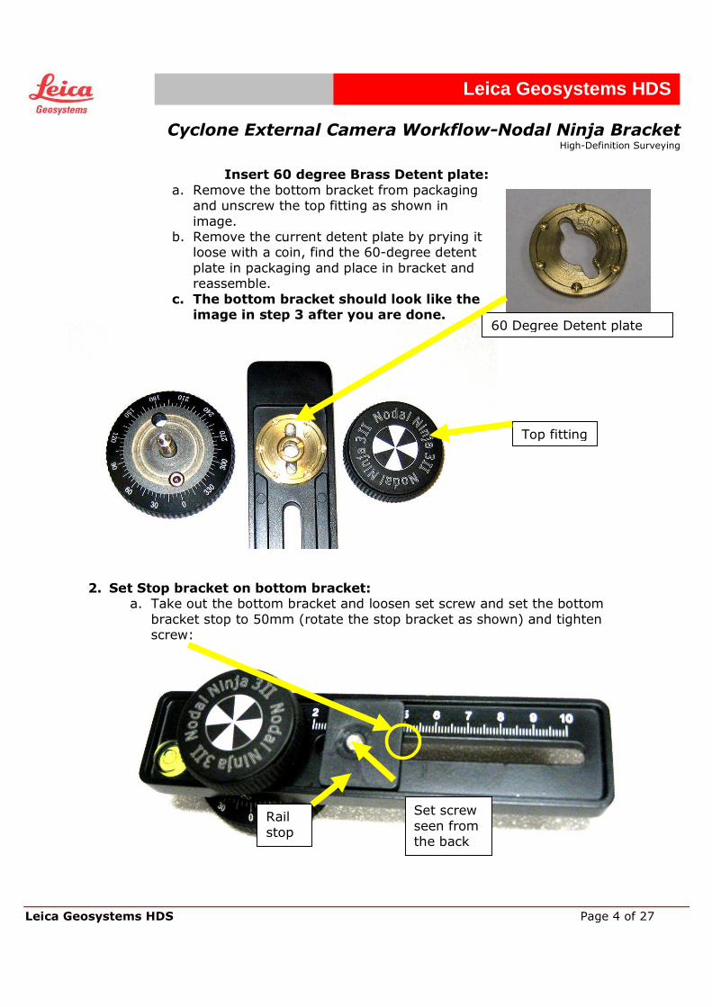
Insert 60 degree Brass Detent plate: a. Remove the bottom bracket from packaging
and unscrew the top fitting as shown in
image. b. Remove the current detent plate by prying it
loose with a coin, find the 60-degree detent
plate in packaging and place in bracket and reassemble.
c. The bottom bracket should look like the image in step 3 after you are done.
2. Set Stop bracket on bottom bracket:
a. Take out the bottom bracket and loosen set screw and set the bottom
bracket stop to 50mm (rotate the stop bracket as shown) and tighten screw:
Set screw
seen from the back
Rail
stop
Top fitting
60 Degree Detent plate
Cyclone External Camera Workflow-Nodal Ninja Bracket
High-Definition Surveying
Leica Geosystems HDS Page 5 of 27
Leica Geosystems HDS
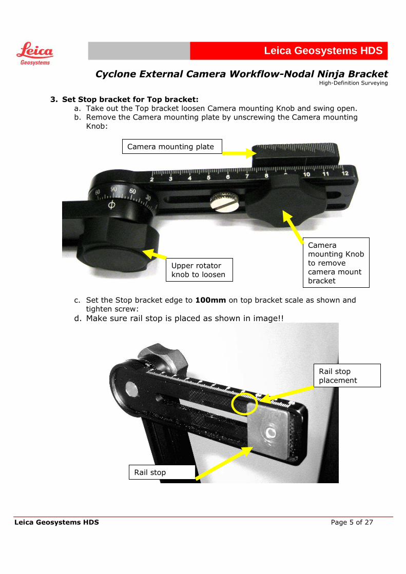
3. Set Stop bracket for Top bracket: a. Take out the Top bracket loosen Camera mounting Knob and swing open. b. Remove the Camera mounting plate by unscrewing the Camera mounting
Knob:
c. Set the Stop bracket edge to 100mm on top bracket scale as shown and
tighten screw:
d. Make sure rail stop is placed as shown in image!!
Rail stop
Rail stop
placement
Upper rotator
knob to loosen
Camera mounting Knob
to remove camera mount
bracket
Camera mounting plate
Cyclone External Camera Workflow-Nodal Ninja Bracket
High-Definition Surveying
Leica Geosystems HDS Page 6 of 27
Leica Geosystems HDS
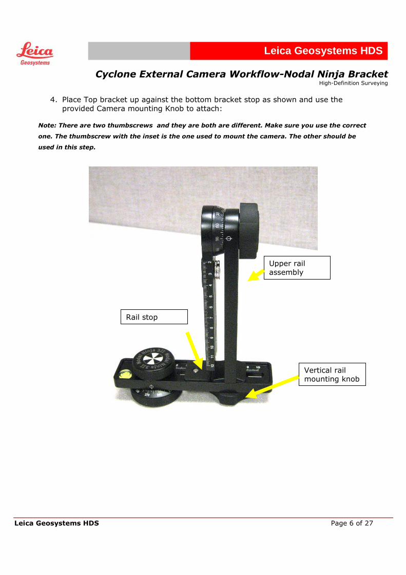
4. Place Top bracket up against the bottom bracket stop as shown and use the
provided Camera mounting Knob to attach: Note: There are two thumbscrews and they are both are different. Make sure you use the correct
one. The thumbscrew with the inset is the one used to mount the camera. The other should be
used in this step.
Upper rail assembly
Vertical rail mounting knob
Rail stop
Cyclone External Camera Workflow-Nodal Ninja Bracket
High-Definition Surveying
Leica Geosystems HDS Page 7 of 27
Leica Geosystems HDS
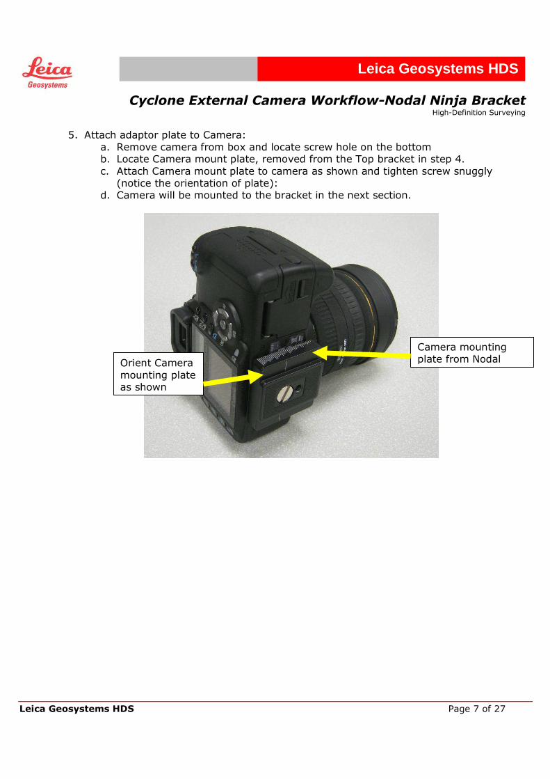
5. Attach adaptor plate to Camera:
a. Remove camera from box and locate screw hole on the bottom b. Locate Camera mount plate, removed from the Top bracket in step 4.
c. Attach Camera mount plate to camera as shown and tighten screw snuggly (notice the orientation of plate):
d. Camera will be mounted to the bracket in the next section.
Camera mounting plate from Nodal Orient Camera
mounting plate as shown
Cyclone External Camera Workflow-Nodal Ninja Bracket
High-Definition Surveying
Leica Geosystems HDS Page 8 of 27
Leica Geosystems HDS
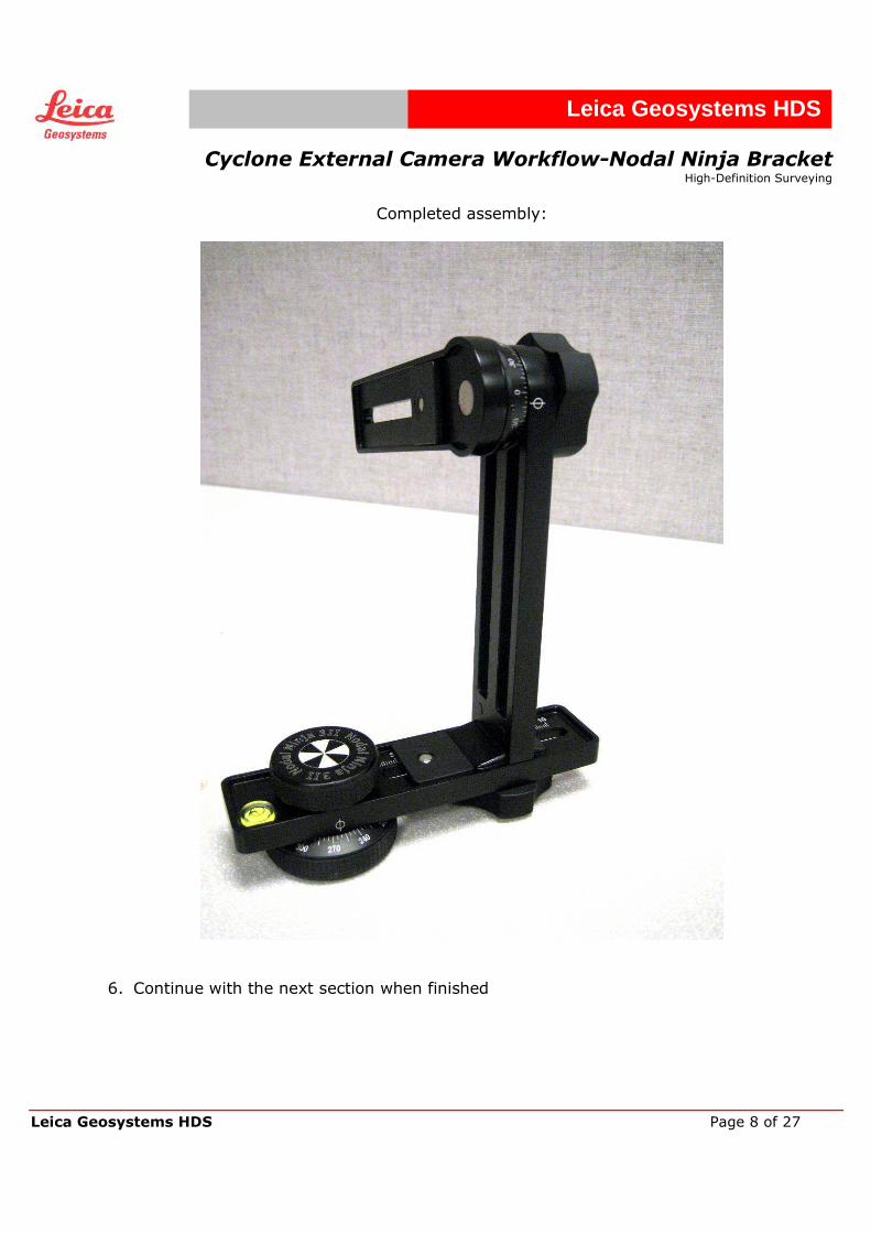
Completed assembly:
6. Continue with the next section when finished
Cyclone External Camera Workflow-Nodal Ninja Bracket
High-Definition Surveying
Leica Geosystems HDS Page 9 of 27
Leica Geosystems HDS
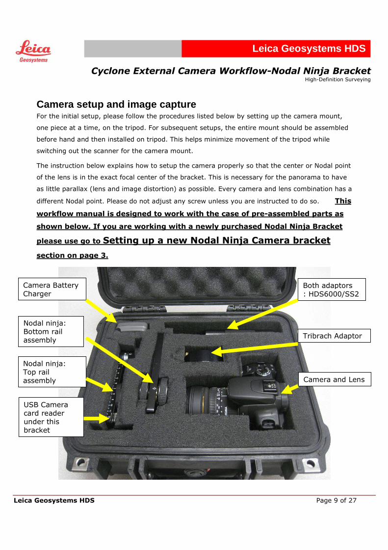
Camera setup and image capture For the initial setup, please follow the procedures listed below by setting up the camera mount,
one piece at a time, on the tripod. For subsequent setups, the entire mount should be assembled
before hand and then installed on tripod. This helps minimize movement of the tripod while
switching out the scanner for the camera mount.
The instruction below explains how to setup the camera properly so that the center or Nodal point
of the lens is in the exact focal center of the bracket. This is necessary for the panorama to have
as little parallax (lens and image distortion) as possible. Every camera and lens combination has a
different Nodal point. Please do not adjust any screw unless you are instructed to do so. This
workflow manual is designed to work with the case of pre-assembled parts as
shown below. If you are working with a newly purchased Nodal Ninja Bracket
please use go to Setting up a new Nodal Ninja Camera bracket
section on page 3.
Both adaptors
: HDS6000/SS2
Nodal ninja: Top rail assembly
Nodal ninja: Bottom rail assembly
Camera Battery
Charger
Tribrach Adaptor
Camera and Lens
USB Camera card reader under this bracket
Cyclone External Camera Workflow-Nodal Ninja Bracket
High-Definition Surveying
Leica Geosystems HDS Page 10 of 27
Leica Geosystems HDS
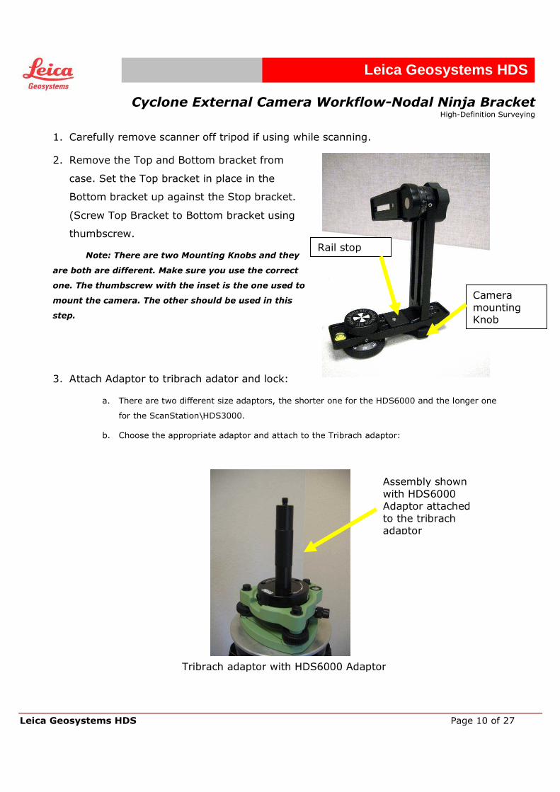
1. Carefully remove scanner off tripod if using while scanning.
2. Remove the Top and Bottom bracket from
case. Set the Top bracket in place in the
Bottom bracket up against the Stop bracket.
(Screw Top Bracket to Bottom bracket using
thumbscrew.
Note: There are two Mounting Knobs and they
are both are different. Make sure you use the correct
one. The thumbscrew with the inset is the one used to
mount the camera. The other should be used in this
step.
3. Attach Adaptor to tribrach adator and lock:
a. There are two different size adaptors, the shorter one for the HDS6000 and the longer one
for the ScanStation\HDS3000.
b. Choose the appropriate adaptor and attach to the Tribrach adaptor:
Assembly shown
with HDS6000 Adaptor attached
to the tribrach adaptor
Tribrach adaptor with HDS6000 Adaptor
Rail stop
Camera
mounting Knob
Cyclone External Camera Workflow-Nodal Ninja Bracket
High-Definition Surveying
Leica Geosystems HDS Page 11 of 27
Leica Geosystems HDS
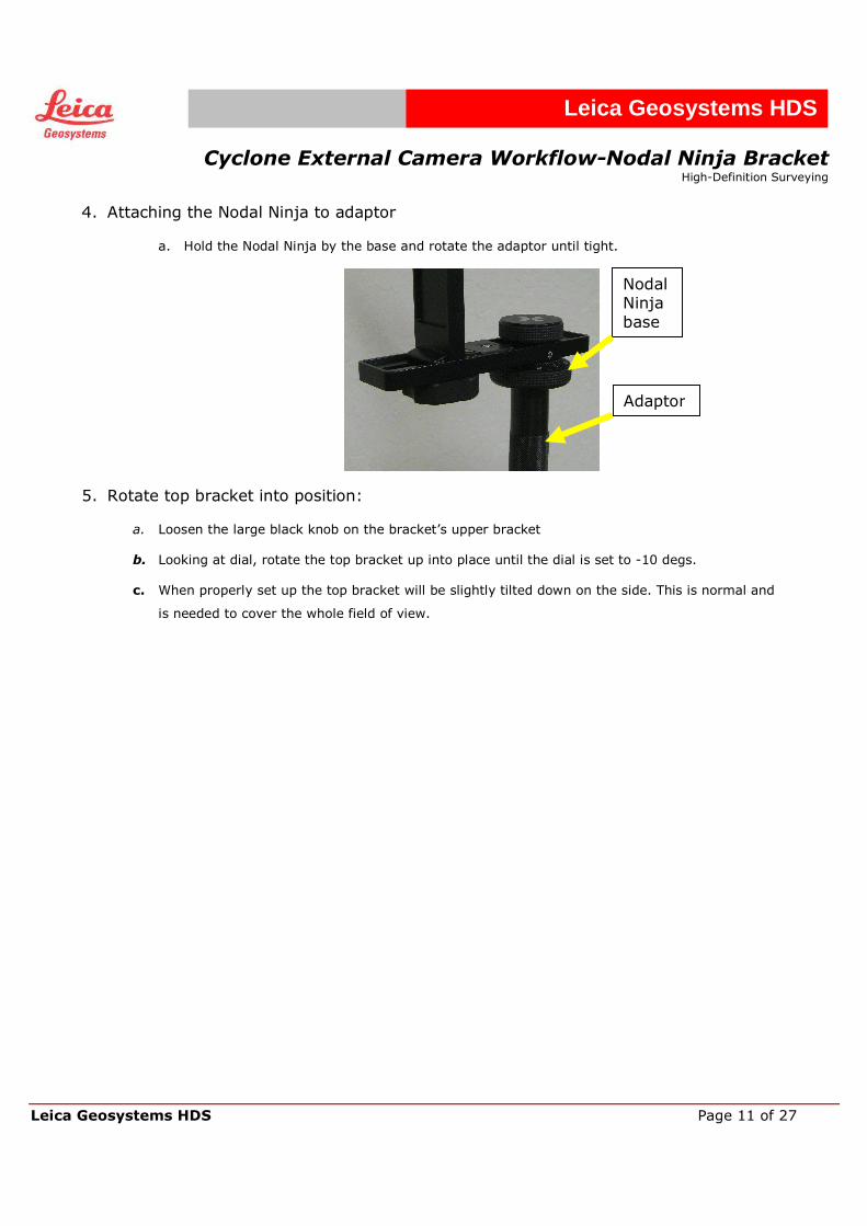
4. Attaching the Nodal Ninja to adaptor
a. Hold the Nodal Ninja by the base and rotate the adaptor until tight.
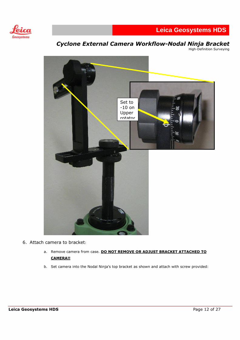
5. Rotate top bracket into position:
a. Loosen the large black knob on the bracket’s upper bracket
b. Looking at dial, rotate the top bracket up into place until the dial is set to -10 degs.
c. When properly set up the top bracket will be slightly tilted down on the side. This is normal and
is needed to cover the whole field of view.
Adaptor
Nodal Ninja
base
Cyclone External Camera Workflow-Nodal Ninja Bracket
High-Definition Surveying
Leica Geosystems HDS Page 12 of 27
Leica Geosystems HDS
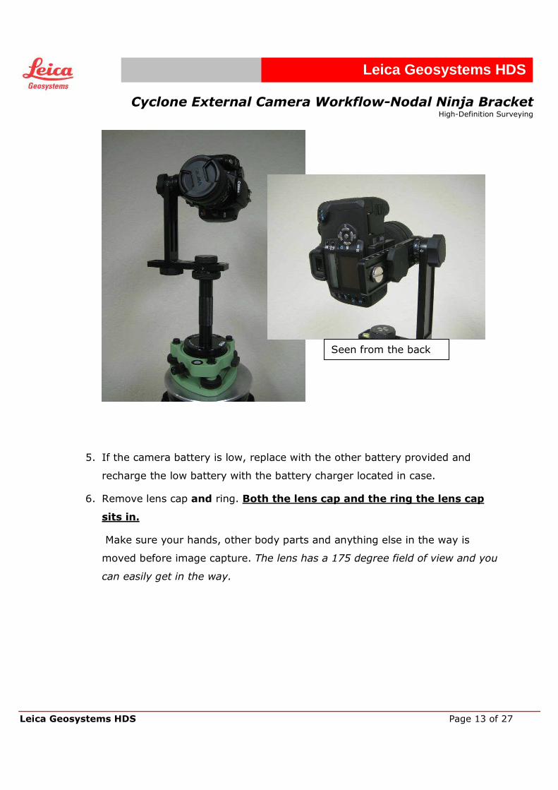
6. Attach camera to bracket:
a. Remove camera from case. DO NOT REMOVE OR ADJUST BRACKET ATTACHED TO
CAMERA!!
b. Set camera into the Nodal Ninja’s top bracket as shown and attach with screw provided:
Set to
-10 on Upper
rotator
Cyclone External Camera Workflow-Nodal Ninja Bracket
High-Definition Surveying
Leica Geosystems HDS Page 13 of 27
Leica Geosystems HDS
5. If the camera battery is low, replace with the other battery provided and
recharge the low battery with the battery charger located in case.
6. Remove lens cap and ring. Both the lens cap and the ring the lens cap
sits in.
Make sure your hands, other body parts and anything else in the way is
moved before image capture. The lens has a 175 degree field of view and you
can easily get in the way.
Seen from the back
Cyclone External Camera Workflow-Nodal Ninja Bracket
High-Definition Surveying
Leica Geosystems HDS Page 14 of 27
Leica Geosystems HDS
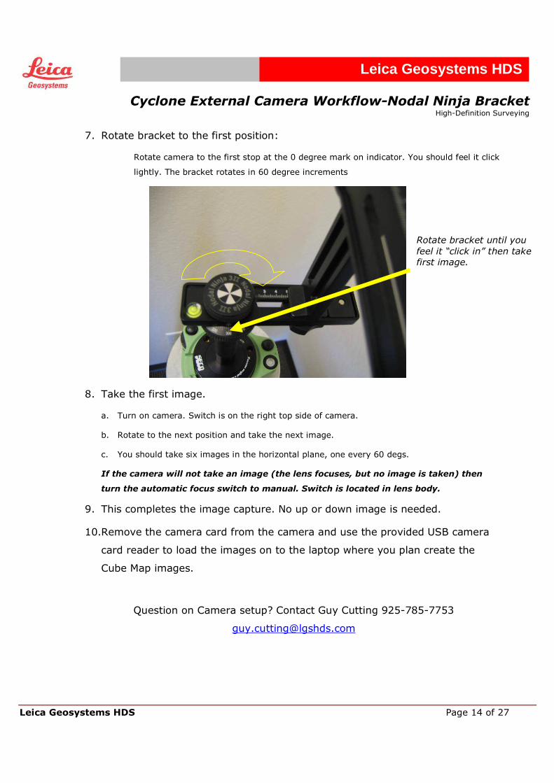
7. Rotate bracket to the first position:
Rotate camera to the first stop at the 0 degree mark on indicator. You should feel it click
lightly. The bracket rotates in 60 degree increments
8. Take the first image.
a. Turn on camera. Switch is on the right top side of camera.
b. Rotate to the next position and take the next image.
c. You should take six images in the horizontal plane, one every 60 degs.
If the camera will not take an image (the lens focuses, but no image is taken) then
turn the automatic focus switch to manual. Switch is located in lens body.
9. This completes the image capture. No up or down image is needed.
10.Remove the camera card from the camera and use the provided USB camera
card reader to load the images on to the laptop where you plan create the
Cube Map images.
Question on Camera setup? Contact Guy Cutting 925-785-7753
Rotate bracket until you
feel it “click in” then take
first image.
Cyclone External Camera Workflow-Nodal Ninja Bracket
High-Definition Surveying
Leica Geosystems HDS Page 15 of 27
Leica Geosystems HDS
Texture Mapping Point Clouds with Panoramic Images
After you take the panoramic images with the camera kit, and transfer the images from the camera to a computer, you need to convert them to a spherical (also known as equirectangluar) image in PTgui. You
then convert that spherical image into Cube Maps that the Cyclone software will synchronize with in order to
complete the workflow.
1. Install PTgui:
• On the attached data disk, go to the Camera Workflow data\Programs\PTgui folder and run
the PTgui 6.0.3 Setup.exe. Follow the instructions in the Setup process.
2. Register PTgui software:
• This process is complete, the PTgui software should be open. You will need to go to
www.ptgui.com and acquire a license ($100). Click on Help on the Toolbar. Then
click on About and at the bottom of the screen, click on “Register . . .”
3. Install Pano tools plug-in:
• Go to the Camera Workflow data\Programs\Pano tools folder and run the setup.exe. At the
prompt that asks if you want to install plug-ins for Photoshop 7.0, click “No”.
4. Apply setting file to PTgui:
• Open PTgui by clicking on the shortcut that you created in the installation process, and go to
File-Apply Template. Browse to the directory Camera Workflow data\Programs\PTgui and
load in the setting file PTgui setting.pts. This file sets all the necessary settings in PTgui.
5. Load images into PTgui:
• On the first page of PTgui click on the Load image… button. Browse to the folder Camera
Workflow data\Sample Data\Images from Camera or your own images and load all the
images. This may take a few minutes. Click ok on the Camera\lens data dialog window that pops
up.
6. Viewing candidate image:
a. Click the Align Images button. Wait a few minutes for PTgui to align images.
b. The Panorama Editor window comes up and you should see the images open randomly and
then adjust to match each other in real time (see image below); if not restart PTgui.
Cyclone External Camera Workflow-Nodal Ninja Bracket
High-Definition Surveying
Leica Geosystems HDS Page 16 of 27
Leica Geosystems HDS
c. If the images do not appear to align well, go to Mode-Edit individual images in the
Panorama Editor window. You can now click on individual images and move them into
place. The images provided in this example will align correctly. (See image below). Unless
there are very few unique objects in the overlap areas of the images (think Cloud-to-Cloud
reg), your images should align correctly without manual adjustment.
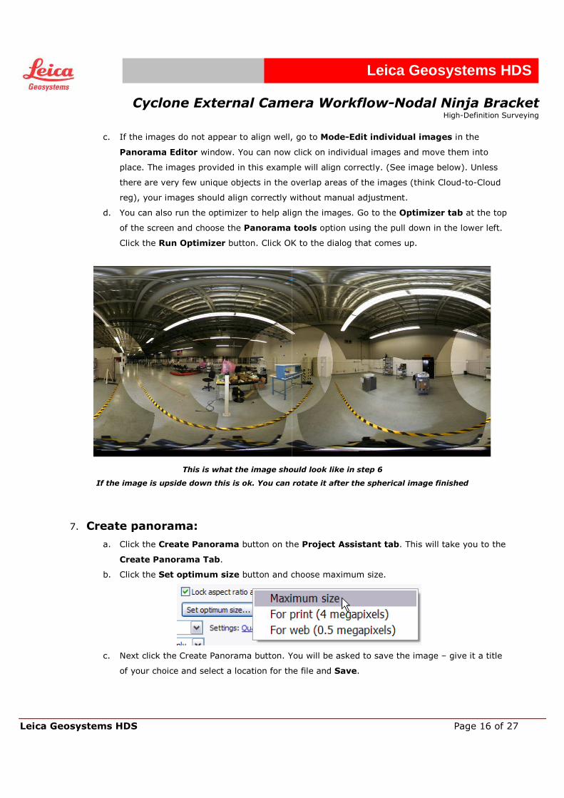
d. You can also run the optimizer to help align the images. Go to the Optimizer tab at the top
of the screen and choose the Panorama tools option using the pull down in the lower left.
Click the Run Optimizer button. Click OK to the dialog that comes up.
This is what the image should look like in step 6
If the image is upside down this is ok. You can rotate it after the spherical image finished
7. Create panorama:
a. Click the Create Panorama button on the Project Assistant tab. This will take you to the
Create Panorama Tab.
b. Click the Set optimum size button and choose maximum size.
c. Next click the Create Panorama button. You will be asked to save the image – give it a title
of your choice and select a location for the file and Save.
Cyclone External Camera Workflow-Nodal Ninja Bracket
High-Definition Surveying
Leica Geosystems HDS Page 17 of 27
Leica Geosystems HDS
8. Close PTgui when alignment (stitcher) finishes.
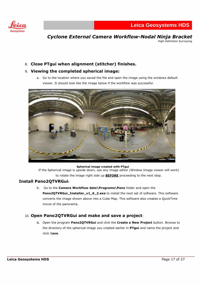
9. Viewing the completed spherical image:
a. Go to the location where you saved the file and open the image using the windows default
viewer. It should look like the image below if the workflow was successful.
Install Pano2QTVRGui:
b. Go to the Camera Workflow data\Programs\Pano folder and open the
Pano2QTVRGui_Installer_v1_6_2.exe to install the next set of software. This software
converts the image shown above into a Cube Map. This software also creates a QuickTime
movie of the panorama.
10. Open Pano2QTVRGui and make and save a project:
a. Open the program Pano2QTVRGui and click the Create a New Project button. Browse to
the directory of the spherical image you created earlier in PTgui and name the project and
click Save.
Spherical image created with PTgui
If the Spherical image is upside down, use any image editor (Window Image viewer will work)
to rotate the image right side up BEFORE proceeding to the next step.
Cyclone External Camera Workflow-Nodal Ninja Bracket
High-Definition Surveying
Leica Geosystems HDS Page 18 of 27
Leica Geosystems HDS
11. Open Spherical image:
a. In the Projects tab under Project type, click the small button next to Equirectangluar
and browse for the image you created earlier in PTgui and click Open.
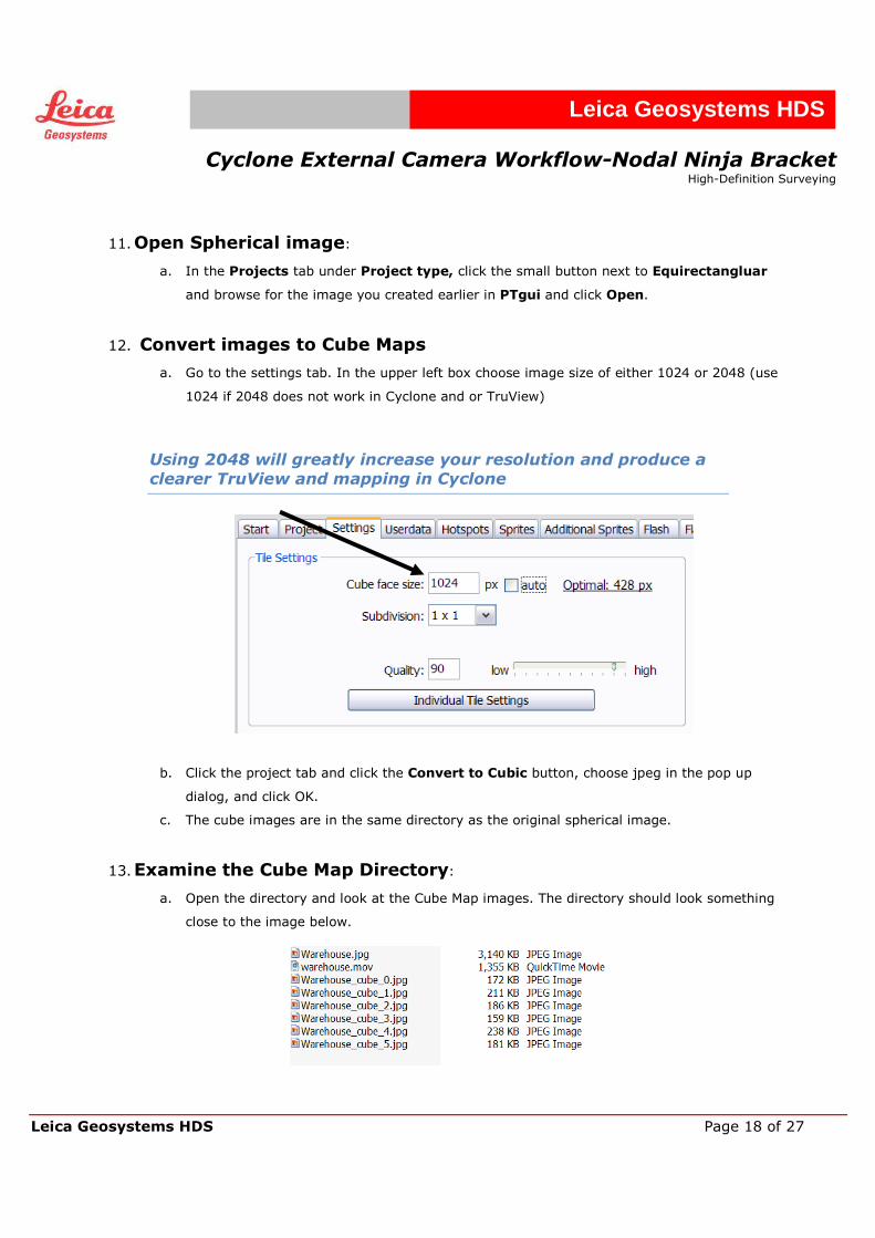
12. Convert images to Cube Maps
a. Go to the settings tab. In the upper left box choose image size of either 1024 or 2048 (use
1024 if 2048 does not work in Cyclone and or TruView)
Using 2048 will greatly increase your resolution and produce a
clearer TruView and mapping in Cyclone
b. Click the project tab and click the Convert to Cubic button, choose jpeg in the pop up
dialog, and click OK.
c. The cube images are in the same directory as the original spherical image.
13. Examine the Cube Map Directory:
a. Open the directory and look at the Cube Map images. The directory should look something
close to the image below.
Cyclone External Camera Workflow-Nodal Ninja Bracket
High-Definition Surveying
Leica Geosystems HDS Page 19 of 27
Leica Geosystems HDS
b. You can open the Warehouse.mov file and check out the movie.
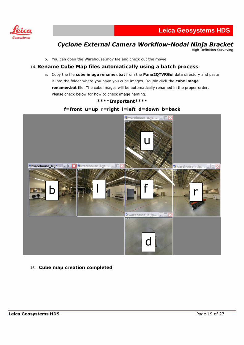
14. Rename Cube Map files automatically using a batch process:
a. Copy the file cube image renamer.bat from the Pano2QTVRGui data directory and paste
it into the folder where you have you cube images. Double click the cube image
renamer.bat file. The cube images will be automatically renamed in the proper order.
Please check below for how to check image naming.
****Important****
f=front u=up r=right l=left d=down b=back
15. Cube map creation completed
u
b l f r
d
Cyclone External Camera Workflow-Nodal Ninja Bracket
High-Definition Surveying
Leica Geosystems HDS Page 20 of 27
Leica Geosystems HDS
Import cube images into Cyclone A complete end-to-end movie of the entire workflow is in the data directory under
Camera Workflow data\Process movie PTgui to Cyclone
You can use the example IMP database in Camera Workflow data\Sample Data\Cyclone
Database\warehouse.imp. This database matches the warehouse images in the PTgui section
above.
1. Importing images into Cyclone:
a. Open Cyclone and browse to the ScanWorld’s image folder
b. Right click on the image folder and choose import. Select all the cube images and click ok.
2. Select cloud/clouds:
a. Open a ModelSpace containing the clouds you wish to texture map. Select the clouds and
merge them, only if there is more than one point cloud you want to texture at once. Then go
to Create Object-Merge to merge all clouds into one object.
3. Add Cube Map images:
a. Go to Edit Object-Appearance-Texture Map Browser. Make sure to have the cloud
selected. Click the (add cube map images) button in the Texture Map Browser. Browse
to the image folder in the Select Project with Cube-Map Image dialog and click OK.
4. Adding constraints (matching picks):
a. You need at least 3 pairs of matching picks to compete the texture mapping
b. Select the points that define a corner, edge or other well defined point.
c. Select first pick in the image dialog (cube map)
i. Click and hold down the left mouse in the dialog (notice the zoom to enable accurate
picking)
ii. When you release the mouse a pick will be left behind
d. Next pick a matching pick in the point cloud window
e. Click the (add constraints) button in the Texture Editor dialog (the smaller one).
f. Right click in the Texture Editor (image) dialog and select another image, either front,
back, right, left, or up and pick another matching set and click the in the Texture Editor
window.
Cyclone External Camera Workflow-Nodal Ninja Bracket
High-Definition Surveying
Leica Geosystems HDS Page 21 of 27
Leica Geosystems HDS
g. If the fit is bad go back and add more picks. You can add multiple picks to each cube. On
scans of streets or roads with long distances, more and better picks are required.
h. Do this again in another view, either front, back, right, left, or up and click the button
again.
i. You only need three matching picks
j. Click the button in the texture Editor Window (the small one) to compute the fit.
k. Click close to all dialogs.
5. Change Cloud to New Colors from Cube Map:
a. Select point cloud and go to Edit Object-Appearance-Apply Color Map-Image Texture
Map to see the new colors from the Cube Map.
b. If you do not see the cube map colors go to View\Global texture Map and make sure it is
checked
c. Check under Edit Object-Appearance-Global Color Map and make sure global color map
is turned off
d. If the fit is not correct go back to the Texture Map Browser and double click on the image,
this will open the contain dialog, and add and or delete picks to get a better fit.
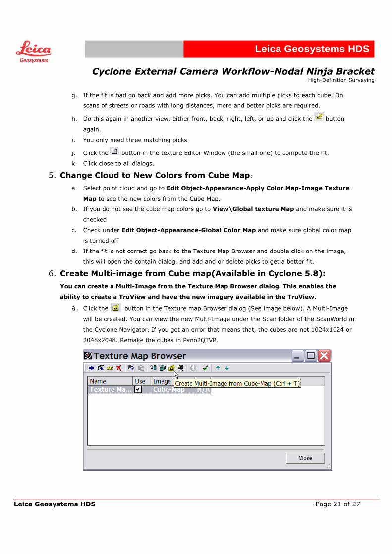
6. Create Multi-image from Cube map(Available in Cyclone 5.8):
You can create a Multi-Image from the Texture Map Browser dialog. This enables the
ability to create a TruView and have the new imagery available in the TruView.
a. Click the button in the Texture map Browser dialog (See image below). A Multi-Image
will be created. You can view the new Multi-Image under the Scan folder of the ScanWorld in
the Cyclone Navigator. If you get an error that means that, the cubes are not 1024x1024 or
2048x2048. Remake the cubes in Pano2QTVR.
Cyclone External Camera Workflow-Nodal Ninja Bracket
High-Definition Surveying
Leica Geosystems HDS Page 22 of 27
Leica Geosystems HDS
7. Create a TruView with the new Multi-Image:
a. You will need to “Burn” the colors to the point cloud to make the point cloud
show the new colors in the TruView. This is because the only option beside
intensity map is “colors from scanners” in the TruView publisher dialog. In
step 6 above check the green check button in the Texture Map Browser to
burn the colors to the point cloud and restart Cyclone
b. The TruView Publisher will use the first Multi-Image in the Image folder.
When you created the Multi-Image from cubes on step 6 above, Cyclone
named the new Multi-Image- Multi-Image2. You need to cut and paste the
original Multi-Image- Multi-Image1 and paste it into another folder (just
create a new one).
c. When you publish the TruView make sure you check the Use Backround
image box in the Publisher dialog that comes up.
8. Workflow finished
Cyclone External Camera Workflow-Nodal Ninja Bracket
High-Definition Surveying
Leica Geosystems HDS Page 23 of 27
Leica Geosystems HDS
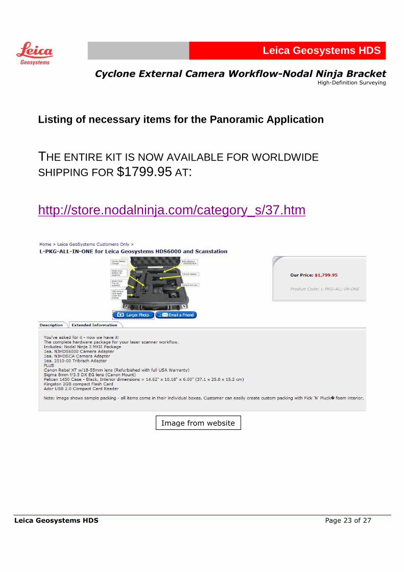
Listing of necessary items for the Panoramic Application
THE ENTIRE KIT IS NOW AVAILABLE FOR WORLDWIDE SHIPPING FOR $1799.95 AT:
http://store.nodalninja.com/category_s/37.htm
Image from website

Cyclone External Camera Workflow-Nodal Ninja Bracket
High-Definition Surveying
Leica Geosystems HDS Page 24 of 27
Leica Geosystems HDS
CAMERA IMAGE TO SPHERICAL IMAGE SOFTWARE: ALL OF THIS SOFTWARE IS AVAILABLE ON THE CAMERA SITE AND ON A CD WHEN YOU ORDER THE KIT FROM NODEL NINJA.
PTGUI: COST $100.00 www.ptgui.com
FREE SOFTWARE:
PANO TOOLS NECESSARY PLUG-IN FOR PTGUI: FREE AND INCLUDED AT: http://software.lgshds.com/public/camera/
PANO2QTVR SPHERICAL IMAGE TO CUBE MAPS
FREE AND INCLUDED AT: http://software.lgshds.com/public/camera/
Cyclone External Camera Workflow-Nodal Ninja Bracket
High-Definition Surveying
Leica Geosystems HDS Page 25 of 27
Leica Geosystems HDS
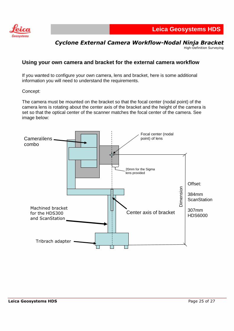
Using your own camera and bracket for the external camera workflow
If you wanted to configure your own camera, lens and bracket, here is some additional information you will need to understand the requirements. Concept: The camera must be mounted on the bracket so that the focal center (nodal point) of the camera lens is rotating about the center axis of the bracket and the height of the camera is set so that the optical center of the scanner matches the focal center of the camera. See image below:
Center axis of bracket
Focal center (nodal point) of lens Camera\lens
combo
Dim
ensi
on
20mm for the Sigma lens provided
Offset: 384mm ScanStation 307mm HDS6000
Machined bracket for the HDS300
and ScanStation
Tribrach adapter
Cyclone External Camera Workflow-Nodal Ninja Bracket
High-Definition Surveying
Leica Geosystems HDS Page 26 of 27
Leica Geosystems HDS
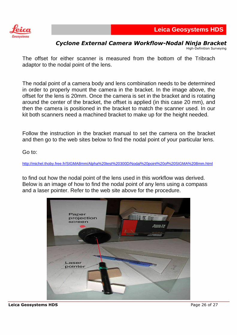
The offset for either scanner is measured from the bottom of the Tribrach adaptor to the nodal point of the lens. The nodal point of a camera body and lens combination needs to be determined in order to properly mount the camera in the bracket. In the image above, the offset for the lens is 20mm. Once the camera is set in the bracket and is rotating around the center of the bracket, the offset is applied (in this case 20 mm), and then the camera is positioned in the bracket to match the scanner used. In our kit both scanners need a machined bracket to make up for the height needed. Follow the instruction in the bracket manual to set the camera on the bracket and then go to the web sites below to find the nodal point of your particular lens. Go to: http://michel.thoby.free.fr/SIGMA8mm/Alpha%20test%20300D/Nodal%20point%20of%20SIGMA%208mm.html
to find out how the nodal point of the lens used in this workflow was derived. Below is an image of how to find the nodal point of any lens using a compass and a laser pointer. Refer to the web site above for the procedure.
Cyclone External Camera Workflow-Nodal Ninja Bracket
High-Definition Surveying
Leica Geosystems HDS Page 27 of 27
Leica Geosystems HDS
These are good web sites for understanding the stitching of photos to form a panoramic image: http://stitcher.realviz.com/
http://stitcher.realviz.com/image-stitching-tutorials/stitching-tutorials/panorama-parallax-1.php
http://www.thegnomonworkshop.com/dvds/gdo01.html
These web sites are good resources for Nodal point location of various lenses: www.hugha.co.uk/NodalPoint http://michel.thoby.free.fr/SIGMA8mm/Alpha%20test%20300D/Nodal%20point%20of%20SIGMA%208mm.html
Download site for Camera workflow:
http://software.lgshds.com/public/camera/