MANUAL FOR MODEL FD4 FIRE PUMP CONTROLLERS€¦ · · 2017-09-21MANUAL FOR MODEL FD4 FIRE PUMP...
34
Metron, Inc. Date: 03/22/04 Approved: MH DOC#: 586 Revision: P Date: 03/15/15 Approved: RA Page: 1 of 34 MANUAL FOR MODEL FD4 FIRE PUMP CONTROLLERS Firmware version 5.02 This manual provides General Information, Installation, Operation, Maintenance and System Set-Up Information for METRON Model FD-4 Engine Driven Fire Pump Controllers. TABLE OF CONTENTS PART I General Information ........................................................................................................................................ PAGE 3 PART II Functions ......................................................................................................................................................... PAGE 3 PART III Operation of the Controller ............................................................................................................................. PAGE 4 PART IV Installation & Test Procedure ......................................................................................................................... PAGE 5 PART V Additional Optional Features ......................................................................................................................... PAGE 9 PART VI Operator Interface Device (OID) Use and Navigation ........................................................................ PAGE 10 PART VII System Set Point Definitions ........................................................................................................................ PAGE 18 PART VIII Alarm and Event Log Messages................................................................................................................... PAGE 22 PART IX SD Card File Format .................................................................................................................................... PAGE 25 Appendix A Modbus Protocol ........................................................................................................................................... PAGE 29 METRON, INC. Hubbell Industrial Controls Inc. 4301 Cheyenne Drive, Archdale, NC 27263 www.metroninc.com Telephone: (336) 434-2800 Ext. 183
-
Upload
vuongxuyen -
Category
Documents
-
view
229 -
download
1
Transcript of MANUAL FOR MODEL FD4 FIRE PUMP CONTROLLERS€¦ · · 2017-09-21MANUAL FOR MODEL FD4 FIRE PUMP...

Metron, Inc. Date: 03/22/04 Approved: MH DOC#: 586
Revision: P Date: 03/15/15 Approved: RA Page: 1 of 34
MANUAL FOR MODEL FD4 FIRE PUMP CONTROLLERS
Firmware version 5.02 This manual provides General Information, Installation, Operation, Maintenance and System Set-Up Information for METRON Model FD-4 Engine Driven Fire Pump Controllers.
TABLE OF CONTENTS PART I General Information ........................................................................................................................................ PAGE 3 PART II Functions ......................................................................................................................................................... PAGE 3 PART III Operation of the Controller ............................................................................................................................. PAGE 4 PART IV Installation & Test Procedure ......................................................................................................................... PAGE 5 PART V Additional Optional Features ......................................................................................................................... PAGE 9 PART VI Operator Interface Device (OID) Use and Navigation ........................................................................ PAGE 10 PART VII System Set Point Definitions ........................................................................................................................ PAGE 18 PART VIII Alarm and Event Log Messages ................................................................................................................... PAGE 22 PART IX SD Card File Format .................................................................................................................................... PAGE 25 Appendix A Modbus Protocol ........................................................................................................................................... PAGE 29
METRON, INC. Hubbell Industrial Controls Inc.
4301 Cheyenne Drive, Archdale, NC 27263 www.metroninc.com
Telephone: (336) 434-2800 Ext. 183

Page 2 of 34
File Name: Doc#586p.docx
THIS PAGE IS BLANK

Page 3 of 34
File Name: Doc#586p.docx
PART I: GENERAL INFORMATION
The basic function of the model FD4 Fire Pump Controller for diesel engine driven fire pumps is to automatically start the engine upon a drop in pressure in the water main, or from a number of other demand signals. This controller provides automatic cycled cranking, alarm and/or alarm shutdown protection for various engine failures. Stopping of the engine after the demand period is over may be either manual or automatic. This controller also includes an automatic weekly test starting feature.
QUICK START FEATURE The quick start feature prompts the user to set up quickly the essential screens for correct use of this fire pump controller. This feature is initiated by pressing and holding the ‘3 PILOT push button for 2s. Then the following screens will be required to be completed in the following order: Start pressure Stop pressure Delay start Time Date Weekly start time Weekly start day Commissioned date Double skinned fuel tank Electronic Engine.
PART II: FUNCTIONS
Equipment is provided in the Controller to provide the following functions:
A. Automatic Starting From: a. Drop in water line pressure b. Loss of battery charger output (if enabled) c. Operation of optional remote start switches, such as remote start switch, deluge valve switch, fire alarm switch, etc. d. Weekly test timer
B. OID – Operator Interface Device - Provided for display of alarm functions, system pressure, battery volts, battery charger amps, alarm conditions, etc. Includes a 4 line by 20 character LCD for display of system messages and programming.
C. Auto-Off-Manual selector switch.
D. Automatic Cranking - A microprocessor controlled crank cycle timer provides six (6) fixed crank periods separated by five (5) rest periods each of approximately 15 seconds duration.
E. Alarms and Signal Lights – Twenty Two (22) Standard lights are provided to give visual signals for; "System Fault”, "Battery #1 Healthy”, Battery #2 Healthy", "Charger #1 Failure", Charger #2 Failure”, “AC Power Loss”, “Engine Running”, "Engine Failed to Start", "Engine Low Oil Pressure", "Engine High Water Temp", "Engine Overspeed", “Low Fuel”, ”ECM Failure”,”ECM Warning”,ECM Sw.in Alt.”, ”ECM Injection Fault”, “Fuel Tank Leak”,”Clogged Water Strainer”,“High Cooling Water Temp”, “Low Engine Temp”, ”Contactor Coil Failure”, and “Pump On Demand”. In addition the mode buttons have LED’s on the button indicating “Auto”, Manual”, “Test”, or “Off” mode. 2 additional lights, configurable by the factory, can be provided for "Pump Room Alarms". An audible alarm horn is mounted on the front of the cubicle for sounding in the event of failure. Terminals are provided for remote failure indication of the following:
"Automatic Mode" "System Fault" "Engine Running (2 sets)" "Common Battery Fault"
First Out Annunciation This feature can be turned on via screen 313. The STND is no first out alarm sequence. F3A: This feature when turned on, will make the first alarm to occur fast flash, then all subsequent alarms slow flash. A first out reset input is required, to clear the first alarm (Pilot pushbutton currently). Pressing the mute pb will turn all slow flashing alarms to steady, First out alarm will slow flash. F1A This feature when turned on, will make the first alarm to occur flash, then all subsequent alarms will show steady. A first out reset input is required (Pilot pushbutton currently), to clear the first alarm. Pressing the mute pushbutton will silence the mutable alarms, First out alarm will be on steady.

Page 4 of 34
File Name: Doc#586p.docx
F. A data logger is provided as standard to record system pressure along with numerous alarm conditions and system events. The data can be displayed on the OID or can be downloaded to a PC through the RS485 port provided on the main system board. Data is stored on an SD Memory card. This card contains individual pressure files with each file containing one days worth of pressure data. Each file is of the PressXXX.txt format. Each entry is stamped with the date and time and system pressure at that time. The Events.txt file contains all of the logged events with each event stamped with date and time. The SD memory card can be removed and files transferred directly to a PC using appropriate memory card reader. The controller will continue to operate normally with the SD card removed. There will, however, be a visual and audible alarm when the card is removed. Events and pressure data will continue to be logged while the card is missing. The memory cards should be replaced within 12 hours to ensure that no data is lost.
G. A weekly test timer is supplied to automatically start the engine any set day of the week, at a set time of day, and a preset run time. See Part IV below for more information and the System Config Screen 106.
H. "Stop" Pushbutton - A pushbutton is provided to stop the engine in Auto at any time provided all starting demands have cleared. This returns the controller to the automatic position. The Auto-Off-Manual selector switch can also be put in the “Off” mode to stop the engine. Any starting commands will not start the engine in the “Off” mode.
I. Integral Battery Chargers (Option J). There are two separate fully automatic, solid state chargers provided for maintaining full charge on the dual sets of engine batteries. An LED display is provided on each charger to indicate charger AC input voltage is present and DC output voltage is present.
User Preferences Screen 218 and 219 are used to determine when the Charger Failure alarm will activate. When Screen 218 is set to No, the Charger Failure alarm will not be active while the engine is running. Should both chargers fail or switch off due to a high voltage output from the engine alternator, the AC Power Failure lamp may come on. This is normal. It will reset automatically once the engine stops running and the charger failure alarms reset. When Screen 218 is set to Yes, the Charger Failure alarm will be active at all times when the Mode selector switch is in the Auto or Manual mode. Screen 219 is used to determine the time delay between the failure contacts on the charger closing and the Charger Failure lamp and audible alarm sounding on the controller.
J. Cabinet - A heavy gauge steel cubicle encloses the controller. The OID, the key operated Auto-Off-Manual (AOM) Selector Switch and manual start pushbuttons are mounted on the outer door. The battery circuit breakers are located inside the cabinet on the main back panel of the unit. A key for the AOM switch is stored in a break-glass housing on the door of the cabinet. An additional key is located inside the cabinet.
PART III: OPERATION OF THE CONTROLLER
A. When the controller is the "Auto" mode and both circuit breakers are in the "On" position, the controller is in standby condition ready to start the engine automatically. A green pilot light above the "Auto" button will illuminate in this mode. Also, Battery #1 Fault and Battery #2 Fault lights should be off indicating that battery power is available.
When the water pressure drops below a level which is set in System Config Screen 101, the Controller will actuate the starter motor and the cranking cycle will commence. In addition the “Pump on Demand” light will illuminate. If the engine starts and runs, cranking will cease and the protective circuits will be operative. If the engine fails to start after six (6) crank periods, cranking will cease, the "Engine Failed to Start" light will illuminate, and the alarm horn will sound. The fuel solenoid will stay on for one hour however. This is to allow the engine to continue to run in the event the failed to start condition was due to a faulty speed switch signal from the engine. The battery alternating circuit alternates batteries on each crank attempt unless one battery is in a discharged state and incapable of cranking the engine. In this instance, the control will lock onto the other battery for the remaining cranking attempts. Dry contacts for remote indication of "Battery Failure" are provided.
The panel is wired so that optional remote start switches may be used, such as Deluge Valve, Remote Start pushbutton, External Pressure , These start switches will also cause the “Pump on Demand” light to illuminate.etc. In addition, when “Power Failure Engine Startup” feature is enabled (System Config Screen 111), the Controller will automatically start the engine upon loss of Battery Charger output or AC Power loss, after an adjustable time delay (System Config Screen 112).
While the engine is running, all protective circuits are operative. If the engine stops while running, and there is still an auto start demand, the control will attempt to restart the engine. If the engine fails to start the "Engine Failed to Start" light will illuminate and the alarm will sound. If, while the engine is operating, the oil pressure drops below a safe limit, the “Low Oil Pressure” light will illuminate immediately. After approximately seven (7) seconds the alarm will sound. Should the engine temperature exceed a safe limit while running, the “Engine High Water Temp.” light will illuminate after a seven (7) second time delay and the alarm will sound indicating engine overheating.
Page 5 of 34
File Name: Doc#586p.docx
In case of Overspeed, the engine will be stopped and the "Engine Overspeed" light will illuminate and the alarm will sound. The light and alarm will stay on until the Engine Speed Switch and the Controller are manually reset. To manually reset the Controller, turn the controller selector switch to Off, then press the Reset button. Then turn the selector switch back to “Auto”.
The Controller may be configured as either "Manual" or "Automatic" stop as required (System Config Screen 104). "Manual" stop is set as standard. The current status of this setting is visible on the Main System Status Screen where the letter “A” will appear in the upper right hand corner of the screen when set to Automatic Stop and an “M” will appear when set for Manual stop. When Automatic stop is enabled the stop timer is preset at the factory to 30 minutes. Longer time settings can be set in System Config screen 105 with a maximum setting of 60 minutes possible. When “Automatic Stop” is disabled, the engine will continue to run even though the pressure switch or other remote starting switch returns to its normal position. The engine can be stopped immediately only by pressing the stop button or by turning the Auto-Off-Manual switch to the Off position. On engines that do not use the “energize to stop” method (i.e. Caterpillar), the engine may also be stopped by turning the circuit breakers BATT1 and BATT2 to OFF. If set up for "Automatic" stop, the engine will be stopped automatically upon restoration to normal of whatever demand switch started the engine providing it has run at least 30 minutes or longer as set in System Config screen 105. If the demand period was less than the time set on the auto stop timer, the engine will continue to run until the timer times out and then will stop.
B. When the "Test" mode button is pressed for two or more seconds, the engine will be started by causing a drop in water pressure. Failure alarm circuits will be operative in the "Test" mode. This method of starting provides a test of the Controller, thereby assuring proper operation when required. The engine will run for the time set in Auto Weekly Test Length Of Run Time (System Config Screen 109) or until the "Stop" push button is pressed or the selector switch is turned to “OFF”.
C. The "Manual" position of the Auto-Off-Manual switch is for manually starting the engine from either battery. The fuel and water solenoids are energized in this position, and the engine must be cranked by pushing one of the buttons located below the OID. "Manual Crank 1" cranks from Battery 1, and "Manual Crank 2" cranks from Battery 2. Pressing both buttons will result in cranking from both batteries simultaneously.
D. When the engine is given a command to stop for any reason, terminal 12 will energize and will remain on for approximately 15 seconds. The controller will not start until terminal 12 is de-energized again.
E. Periodic Self Testing - The Test Run Timer can be set to give test runs on any day of the week and time of day desired. A timing element is incorporated in the control so that when the engine starts in this manner, it will run for a definite time before it shuts down. See System Config Screens 106 through 109 to set the starting time and length of engine running.
F. Provision for sequential starting is accomplished by the use of adjustable time delay on pressure drop starting or “Deluge Valve” starting. On Multiple Pump installations these timers are set sequentially and progressively longer in time to prevent more than one (1) pump from starting simultaneously with another pump. Failure of the lead pump to start will not prevent subsequent pumps from starting. The time delay on starting is set in System Config Screen 103.
G. The “Pump On Demand” alarm light is provided to indicate that there is a command to start and run the additive pump controller. This includes a low pressure condition, deluge valve start signal etc. The alarm light will clear when the start condition has been cleared such as the water pressure in the system rises above the high set point set in screen 102.
H. The “Contactor Coil Failure” alarm light is to annunciate a loss of continuity to the two engine starting contactors on the engine. There is a low level DC current that is applied to field terminals #9 and #10 to detect continuity in the contactor coils. Should the contactor coil open or fail, the “Contactor Coil Failure” LED will illuminate and the alarm horn will sound. In addition there will be an entry in the Event log to indicate which Contactor coil has failed.
I. The “Loss of DC Power” lamp is provided to indicate that both batteries have been disconnected or turned off but AC power is still available. The alarm horn will also sound upon the loss of DC Power and can not be silenced.
J. The “ECM Failure”,”ECM Warning”,“ECM Sw. in Alt.” and “ECM Injection Fault” alarms apply only to those engines that have electronic fuel control. Should the Electronic Engine Control Module detect a problem, the appropriate alarm LED will illuminate and sound the horn.
PART IV: INSTALLATION AND TEST PROCEDURE
A. INSTALLATION
The Fire Pump Controller has been assembled and wired at the factory in accordance with the highest workmanship standards. All circuits and functions have been thoroughly tested to assure correct operation when properly installed. The installer should be completely familiar with the external hookup of the engine junction box to the terminal bar in the Controller. Various engine components must be wired to the proper terminal in the controller using the correct size of stranded wire. An appropriate size

Page 6 of 34
File Name: Doc#586p.docx
wire must be wired from the grounding lug in the controller to earth ground. In most cases, the engine manufacturer furnishes the engines with all accessories installed and wired to the connection box. Therefore, it is only necessary to wire from the engine connection box to like numbered terminals in the Controller. Note proper wire sizes. All wires must be stranded.
A drain valve is provided to relieve water pressure to the pressure switch, thus closing the pressure switch contacts and starting the engine. This test simulates an actual start demand. Since the Controller operates the drain valve only momentarily, a small amount of water is drained off. The water pressure sensing line to the Controller from the pump must be thoroughly flushed before connection to the Controller in order to remove chips, particles, or other matter, that could enter the plumbing components in the Controller.
Controllers configured with "Automatic Stop" enabled may be changed to "Manual" stop by disabling this feature in System Config Screen 104. If deluge valve switches are to be used for starting, enable the Deluge Valve Option in Config Screen 121 and connect the remote normally closed switch to terminals 31 and 111.
B. TEST PROCEDURE
All of the following tests should be made on each unit after installation. If each test is satisfactory, the operator may place the control switch in "Auto" mode and depend upon the panel operating properly when required. Also, any one or all of these tests may be carried out at any time after installation, if so desired. NOTE: If 115 Volts A.C. is not connected to Controller, the "Charger Failure" lights and “AC Power Loss” light and alarm will be activated and if the Power Failure Start feature (System Config Screen 111) is enabled, the controller will start automatically. The 115VAC must be turned ON to prevent the engine from starting.
ENGINE TERMINAL (terminals 1-12) STATUS INDICATOR LIGHTS
Light Emitting Diodes (L.E.D.) lights have been installed on the microprocessor module to indicate the status of each engine terminal. Status indication is given below:
Terminal Number L.E.D. (light) "ON" Indication (Microprocessor Func #)
1 (Out 06) Power available to fuel and water solenoids 2 (In 06) Speed switch has operated into engine running mode 3 (In 07) Speed switch has operated into overspeed mode 4 (In 08) Oil Pressure switch contacts closed (Low Oil Pressure) 5 (In 09) Water temperature switch contacts closed (High Engine Temp.) 6 (In 01) Battery #1 voltage present 8 (In 02) Battery #2 voltage present 9 (Out 02) Crank #1 voltage present (while cranking on Battery #1) 10 (Out 03) Crank #2 voltage present (while cranking on Battery #2) 12 (Out 07) Energize to stop voltage present
a. BATTERY LOCKOUT TEST:
1. Turn on Battery #1 switch and Battery #2 switch.
2. Press the "Reset" button. Battery #1 and Battery #2 Healthy lights should be on.
3. Turn Battery #1 switch off for a couple of seconds and back on. Battery #1 light should go off and remain off.
4. Press "Reset" button. Battery #1 light should come on.
5. Repeat for Battery #2.
b. CRANKING CYCLE TEST: This test simulates a condition where the engine refuses to start.
1. Disconnect Terminal No.1 on Controller panel. NOTE: Disconnecting Terminal No.1 is for the purpose of removing power from the fuel solenoid so engine will not start. On engines where the fuel solenoid is not used (Caterpillar), or is connected other than through Terminal #1 (Clarke-G.M.), other means must be used to stop fuel flow to the engine to prevent starting.
2. Press the "Test" mode button to start cranking the engine. Time the crank and rest periods, and count the number of cranks. There should be six (6) crank periods separated by five (5) rest periods each of approximately 15-seconds

Page 7 of 34
File Name: Doc#586p.docx
duration. The "Failed to Start" light should come on and the alarm horn should sound. Status indicator light for Terminal #1 should come on as soon as the "Test" push button is pressed and the pressure drops below the low set point. Indicator lights for terminals 9 and 10 should come on alternately to indicate cranking cycle. (See above)
3. Press the "Stop" push button to stop the engine and properly reconnect all leads.
NOTE: In order to prevent discharging the starting batteries, this same test can be made without actually cranking the engine by disconnecting the starter cable and observing the action of the starter contactors and/or status indicator lights for terminals 9 and 10.
c. CHECKING STARTING MOTOR RELEASE
1. Press the “Test” mode button. Engine should start promptly and starting motor should release at approximately 1/3 of engine speed. Status indicator light for terminal #2 should come on to indicate speed switch has operated to disconnect cranking and the Engine Running LED should illuminate.
NOTE: A convenient method of determining the exact instant the starter releases is to connect a battery test light or voltmeter across the starter terminals and observe when power is disconnected.
2. Press the “Stop” push button to stop the engine.
d. OIL PRESSURE FAILURE TEST:
1. Press the "Test" mode button to start engine. When the engine is starting and oil pressure is not yet up to full pressure, the "Engine Low Oil Pressure" light will illuminate, but the horn will not sound. When pressure builds up, and the switch opens, the light will go out. This feature provides indication that the oil pressure switch contacts are operating in a normal manner.
Note: On Electronic Engines with electronic oil pressure sensors, the oil pressure light may not illuminate while the engine is cranking. The low oil pressure test should be performed on these engines with the engine running as described below.
2. After the engine is running, connect a temporary jumper between terminal #4 and terminal #11.
3. Both the "Engine Low Oil Pressure" light and status indicator light for terminal #4 should come on immediately. Wait approximately seven (7) seconds. Alarm horn should sound.
4. Press the "Stop" push button to stop the engine and remove jumper between terminal #4 and terminal #11.
5. Wait at least 30 seconds for elements to reset before making any further tests.
e. WATER TEMPERATURE FAILURE TEST:
1. Press the "Test" push button to start engine.
2. Jumper contacts on water temperature switch on engine.
3. Alarm horn sounds and the "High Water Temperature" light on controller will illuminate after approximately 7 seconds. Status indicator light for terminal #5 should come on with "High Water Temperature” light.
4. Press the "Stop" push button to stop the engine and remove jumper on water switch.
f. OVERSPEED FAILURE TEST:
1. Press the "Test" mode button to start engine.
2. Momentarily short the contacts on the engine speed switch, or connect a temporary jumper between terminal #3 and #6 on the controller.
3. The alarm horn sounds and the "Engine Overspeed" light will illuminate immediately. Engine comes to a stop. Status indicator lights for terminals #3 and #12 should come on with the "Engine Overspeed" light.
4. Remove the jumper from terminals #3 and #6 then turn the selector switch to the Off position. Press the "Reset" button to reset the “Overspeed” alarm. Turn the selector switch back to the Auto position.
g. CONTACTOR COIL FAILURE ALARM TEST:
1. While the controller is in the "Auto" mode disconnect the field wire from terminal 9. Within a few seconds the "Contactor Coil Failure” lamp should illuminate and the alarm horn should sound. Reconnect the field wire to terminal 9. The "Contactor Coil Failure” lamp should go out and the alarm horn should silence. Repeat for terminal 10.
Page 8 of 34
File Name: Doc#586p.docx
h. AUTOMATIC STARTING TESTS:
1. Place control in "Auto" position.
2. Bleed off pressure in system until pressure drops below the low set point. The “Pump on Demand” light should come on.
3. Engine should start automatically and continue to run after pressure rises above the high set point, if arranged for "Manual" stop. If arranged for "Automatic" stop, engine will continue to run for time set on Engine Run Timer and then stop.
4. Press the "Stop" push button to stop the engine.
5. Repeat tests for each demand switch such as deluge valve, remote start, etc.
i. PERIODIC WEEKLY START TEST:
1. Pressure must be up and all other demand switches de-activated.
2. 115 V.A.C. power must be turned on to the panel.
3. When the current day and time of day matches the settings in System Config screens 107 and 108, the solenoid drain valve will energize and the engine will begin cranking. It will continue to run for the amount of time set.
4. Should a remote manual start occur or a low pressure condition occur while the pump is running on Weekly Test, the pump will not stop until the Stop pushbutton is pressed or if set for Automatic Stop, the Minimum run timer times out.
5. The periodic Weekly Test function is factory set to No in Screen 106 due to Factory Mutual standard requirements. Contact the Metron Factory Service department for instructions to turn this function on if this is not a Factory Mutual insured facility.
j. SETTING PROGRAM WEEKLY TEST TIME: System Config screen 106 through 109.
k. REMOTE START SWITCH CIRCUITS: Field wiring terminals are provided on the controller so that optional remote start switches such as Remote Pushbutton Stations, Deluge Valve Switch, Fire Alarm Switches, etc., may be used to start the engine. Two (2) sets of terminals are provided. Terminals #112 and #31 are used for remote manual start push buttons (close to start). Terminals #111 and #31 are used for remote Deluge Valve Switch or other remote automatic start switches (open to start). Upon automatic start from this type of switch, the engine will be stopped either automatically (if set for automatic stop) after the demand switch de-activates and Engine Auto Stop Timer times out, or manually at the Controller. Terminals #111 and #31 must have a jumper installed if a remote Deluge switch is “Enabled” but not to be used. When the controller is shipped from the factory Deluge Valve start is Disabled (System Config screen 121).
l. AC POWER FAILURE STARTING: If this feature has been enabled it can be tested by disconnecting the normal 115 V.A.C. to the Controller. After the preset time delay (which is specified in System Config screen 112), the Controller will commence cranking the engine. The "Charger #1 Failure”, “Charger #2 Failure”, and “AC Power Loss" lamps will illuminate and the alarm will sound without delay.
m. NORMAL OPERATION – AUTOMATIC: Turn the selector switch to the “Auto" position. A green "Automatic Mode" light will illuminate and the engine will automatically start upon drop in pressure or operation of other start switches. If the Auto Stop Timer is disabled (Manual Stop) the engine must be turned off at the Controller. When the Auto Stop Timer is enabled, upon termination of the demand signal, the engine will run for the length of time left on the Auto Stop Timer and then will stop automatically.
n. AN ADJUSTABLE SEQUENTIAL START TIMER IS SUPPLIED FOR MULTIPLE PUMP INSTALLATION: Normally, the leading pump Controller will not have a delay timer and will commence cranking the engine immediately upon operation of a demand signal (other than Power Failure which is time delayed). The subsequent Controllers will have a time delay which is adjustable from 0 to 999 seconds. Each time delay should be set with progressively longer times on each subsequent pump. The recommended time interval is ten (10) to fifteen (15) seconds. This may be extended or shortened as required by the local authorities having jurisdiction.
o. PUMP ROOM ALARMS: Field terminals may be provided for various inputs from pump room alarms. These alarms include: Low Fuel, Low Pump Room Temperature, Reservoir Low, Reservoir Empty, Low Suction Pressure, Relief Valve Discharge and/or Flow Meter On etc. A maximum of ten (8) pump room alarms are available. The Controller is arranged so that the alarm horn will sound and the light will come on when the alarm sensor contacts close. These pump room alarms can be silenced with the “Silence” push button on the OID if they have been configured as silenceable.

Page 9 of 34
File Name: Doc#586p.docx
p. FOAM PUMP OPTION: An optional feature to operate an external pressure dump valve can be provided for Foam Pump Service if required. Screen 318 is set to approximately 10-15 seconds to operate a dry contact which can be used to operate the Dump Valve solenoid. This contact will close when a demand for the pump to run is received such as low pressure, deluge valve, remote start, weekly test start etc. Once the engine is running, the timing circuit will start and keep the contact close for the length of time set in screen 318. Then it will open and de-energize the dump valve allowing the pump to develop full pressure. In addition, if the controller is not activated by a pressure start, the pressure transducer can be deactivated through screen 319. This will also remove the pressure display from the main status screen of the OID. The controller can only then be activated by a remote start such as deluge valve or remote start contacts. This a factory settable option only and must be ordered with the controller before it ships from the factory.
PART V: ADDITIONAL OPTIONAL FEATURES
A. Battery Charger Operation: The Battery Chargers are mounted in the engine controller, and are factory wired to the controller terminal block from which it obtains its 120 volt, 50-60 Hz. supply voltage, and through which it provides charging current to the batteries. The charging current to the two (2) batteries and the battery voltage is monitored by the controller and displayed on the OID. The charger output is current limited and provides full protection during the engine cranking cycle. The charger input and output are fused for protection in case of a failure of the control circuit or other internal component.
Each battery charger is fully automatic, and will charge the batteries at a rate of up to 10 amperes. As the batteries approach full charge, the current will taper off to a predetermined level at which time the charger automatically switches to the float mode of operation. In the float mode the charger maintains the batteries at the float potential (approximately 12.7 volts for a 12-volt battery or 25.4 volts for the 24-volt battery).
The charger provides a means of monitoring the charger output to sound an alarm in case of loss of charger output. This also provides a means of monitoring the A.C. power since a loss of A.C. power results in a loss of charger output.
Never disconnect the batteries from the controller while the AC power is on to the controller as this may cause damage to the printed circuit boards.
In the event that a battery is lost or disconnected the output of the charger will stop (0 volts). This will allow the voltage sensing circuit of the fire pump controller microprocessor to detect a missing battery or open circuit from the battery. This will result in the respective Battery Fault light to illuminate and the alarm horn to sound. Before reconnecting the battery to the controller, turn the AC power off. Then reconnect the battery to the controller and turn the AC power back on.to reset the alarm.
Generally, when all conditions are normal, the batteries will come to a full charge prior to the 24 hour period. As batteries begin to charge, the controller OID will indicate a gradual decrease in current flow. When these ammeters indicate a current level of less than 0.5 amps the charger will be in a trickle mode.
Check batteries daily for a few days after initial installation has been made, and weekly thereafter. Batteries should be checked for overcharging (gassing), or undercharging (low voltage, or low specific gravity of the electrolyte or acid.
CAUTION: Under no circumstances should new electrolyte (acid) be added to a battery that has been previously filled.
Only distilled water is recommended for maintenance purposes.
Page 10 of 34
File Name: Doc#586p.docx
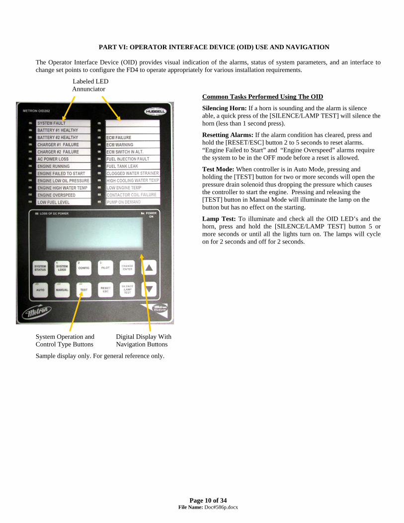
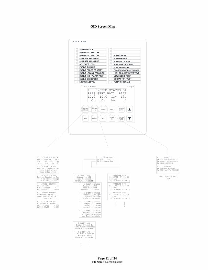
PART VI: OPERATOR INTERFACE DEVICE (OID) USE AND NAVIGATION
The Operator Interface Device (OID) provides visual indication of the alarms, status of system parameters, and an interface to change set points to configure the FD4 to operate appropriately for various installation requirements.
Labeled LED Annunciator
Common Tasks Performed Using The OID
Silencing Horn: If a horn is sounding and the alarm is silence able, a quick press of the [SILENCE/LAMP TEST] will silence the horn (less than 1 second press).
Resetting Alarms: If the alarm condition has cleared, press and hold the [RESET/ESC] button 2 to 5 seconds to reset alarms. “Engine Failed to Start” and “Engine Overspeed” alarms require the system to be in the OFF mode before a reset is allowed.
Test Mode: When controller is in Auto Mode, pressing and holding the [TEST] button for two or more seconds will open the pressure drain solenoid thus dropping the pressure which causes the controller to start the engine. Pressing and releasing the [TEST] button in Manual Mode will illuminate the lamp on the button but has no effect on the starting.
Lamp Test: To illuminate and check all the OID LED’s and the horn, press and hold the [SILENCE/LAMP TEST] button 5 or more seconds or until all the lights turn on. The lamps will cycle on for 2 seconds and off for 2 seconds.
System Operation and Digital Display With Control Type Buttons Navigation Buttons
Sample display only. For general reference only.
Page 11 of 34
File Name: Doc#586p.docx
2 CONFIG1) ANALOG SIGNALS2) AUXILLIARY ALARMS
1 CONFIG1) SYSTEM SETPOINTS2) USER PREFERENCES3) TECH SCREENS
# 1 EVENT DETAILS System in Off Mode Occurred 02/16/03 13:15:15
# 1 EVENT LOG System in Off Mode Occurred 02/16/03 13:15:15
# 1 EVENT DETAILS Pressure: 83.2psi System Auto:Yes Engine Running:No
# 1 EVENT DETAILS Charger #1 OK:Yes Charger #2 OK:Yes Battery #1 OK:Yes
# 1 EVENT DETAILS Battery #2 OK:Yes AC Power Avail:Yes Low Fuel Level:No
# 2 EVENT LOG Engine Failed ToStart Alarm Occurred 02/16/03 07:32:15
# 3 EVENT LOG AC Power Failure Alarm Cleared 02/16/03 07:09:48
PRESSURE LOG 02/16/03 17:52:45 112 psi Skip Rate:[EACH ]
PRESSURE LOG 02/16/03 17:52:30 112 psi Skip Rate:[EACH ]
PRESSURE LOG 02/16/03 17:52:15 113 psi Skip Rate:[EACH ]
SYSTEM LOGS1) Event Log2) Pressure Log
1 SYSTEM STATUS B1PRES STRT BAT1 BAT2110 100 13V 13V psi psi 6A 0A
3 SYSTEM STATUSEngine Countdown Tmr For AC Power Outage 0min Until Start
2 SYSTEM STATUSEngine Countdown Tmr 0sec Until Start 0min Until Stop
5 SYSTEM STATUSFirmware Ver SV 1.1Commissioned Date: 11/15/02
4 SYSTEM STATUSEngine Hrs: 5.3# Of Starts: 8Mon02/17/03 17:53:26
Continued on nextpage.
| || || |
| || || |
AUTO MANUAL TEST
STATUSSYSTEM
LOGSSYSTEM
1
CONFIG
2
METRON OID202
SILENCE
TEST/LAMP
POWER
PILOT
3
ENTERCHANGE/
ESCRESET/
6 SYSTEM STATUSExtended VoltageBAT 1 27.10 0.00ABAT 2 27.05 0.00A
ONLOSS OF DC POWER
OID Screen Map

Page 12 of 34
File Name: Doc#586p.docx
Note: Sample settings shown below. Not to be used to program controller for operation. Consult factory for correct settings for the site conditions.
303 TECH SCREENS Energized To Stop Fuel Solenoid Time[10]seconds 0-99
304 TECH SCREENS Engine Condition Alarm Delay Time[99]seconds 1-99
305 TECH SCREENS Nominal Battery Voltage[24]VDC 10-99
306 TECH SCREENSBattery Low Voltage Alarm Trip Voltage[12.0]VDC 6-99
307 TECH SCREENSBattery Low Voltage Alarm Trip Time[ 2]seconds 0-99
308 TECH SCREENSChange Tech Password
[******]
309 TECH SCREENS Password Logout Time[ 5] minutes 1-15
317 TECH SCREENSAlarm Log 1/10Event Log 1/1569Pr. Log 1/25123
316 TECH SCREENSAlarm resound timers4Hrs 0Min 0Sec24Hrs 0Min 0Sec
314 TECH SCREENS Load OID Hardware Test Mode[NO ]
313 TECH SCREENSAnnunciator Sequence
[STND]
310 TECH SCREENSSystem Commissioned Date[31/12/99] DD/MM/YY
2 CONFIG1) ANALOG SIGNALS2) AUX USER PROGRAMS
1 CONFIG1) SYSTEM SETPOINTS2) USER PREFERENCES3) TECH SCREENS
207 USER PREFERENCES Time BetweenPressure Log Samples[ 15] seconds 15-999
206 USER PREFERENCESLow Pressure EventReset Time[15] seconds 0-20
205 USER PREFERENCESLow Pressure EventTrip Pressure[ 60.0]psi 0-999.9
204 USER PREFERENCESLog System Pressure Drop Events[Yes]
203 USER PREFERENCES Set System Day Of The Week[Sun]
202 USER PREFERENCES Set System Date
[08/10/10] DD/MM/YY
212 USER PREFERENCESLCD Back Light Mode 0=Always on[0]] 1=Power Save
213 USER PREFERENCESLanguage Select0=English, 1=Spanish[0]
214 USER PREFERENCESChange User PasswordLevel 1[****]
201 USER PREFERENCES Set System Real Time Clock[17:03:52]
102 SYSTEM SETPOINTS Engine Stop Pressure[110.0]psi 0-999.9
112 SYSTEM SETPOINTSPower Failure Engine Start Delay Time[ 1] minutes 0-500
115 SYSTEM SETPOINTS Shutdown On Low Intake Contact Type[NO ]
114 SYSTEM SETPOINTS Fail to start inputMB22 for unavailable[No ]
113 SYSTEM SETPOINTSPressure TransducerFailure Engine Start[Yes]
111 SYSTEM SETPOINTSPower Failure Engine Startup[No]
108 SYSTEM SETPOINTS Auto Weekly Engine Test Start Time[10:00:00]
109 SYSTEM SETPOINTS Auto Weekly Test Length Of Run Time[30] minutes 30-99
110 SYSTEM SETPOINTS Auto Weekly Test Oil/Water Shutdown[No]
103 SYSTEM SETPOINTS Engine Start Delay Time[ 1] seconds 1-999
104 SYSTEM SETPOINTS Engine Automatic Stop Enabled[Yes]
105 SYSTEM SETPOINTS Engine Minimum Run Time[30]minutes 30-99
106 SYSTEM SETPOINTS Automatic Weekly Engine Test Run[No]
101 SYSTEM SETPOINTS Engine Start Pressure[100.0]psi 0-999.9
ANALOG INPUT COUNTS 649 1176 1221 12 12
422 ANALOG SIGNALSAnalog Input 3 1225Minimum Counts[ 0]
421 ANALOG SIGNALSAnalog Input 03Offset:[ 0.0000]
420 ANALOG SIGNALSAnalog Input 03Slope:[0.0352500]
412 ANALOG SIGNALSAnalog Input 2 1174Minimum Counts[ 0]
411 ANALOG SIGNALSAnalog Input 02Offset:[ 0.0000]
410 ANALOG SIGNALSAnalog Input 02Slope:[0.0352500]
402 ANALOG SIGNALSAnalog Input 1 651Minimum Counts[ 200]
401 ANALOG SIGNALSAnalog Input 01Offset:[- 76.1904]
400 ANALOG SIGNALSAnalog Input 01Slope:[0.3401360]
502 AUX SETPOINTSAux User Program # 1 Input Number[30] 0-70
512 AUX SETPOINTSAux User Program # 1 Output3 Number[ 0] 0-24
514 AUX SETPOINTSAux User Program # 1 Text Message Number[ 0] 0-32
513 AUX SETPOINTSAux User Program # 1 Record In Event Log[No ]
507 AUX SETPOINTSAux User Program # 1 Horn Enabled[No ]
511 AUX SETPOINTSAux User Program # 1 Output2 Number[ 0] 0-24
510 AUX SETPOINTSAux User Program # 1 Output1 Number[ 0] 0-24
508 AUX SETPOINTSAux User Program # 1 Horn Silence[No ]
509 AUX SETPOINTSAux User Program # 1 LED Number[ 0] 0-24
504 AUX SETPOINTSAux User Program # 1 Trip Time[ 0]sec 0-999
505 AUX SETPOINTSAux User Program # 1 Reset Time[ 0]sec 0-999
506 AUX SETPOINTSAux User Program # 1 Auto Reset Enabled[Yes]
503 AUX SETPOINTSAux User Program # 1 Input Contact Type[NO ]
501 AUX SETPOINTSAux User Program # 1 Enabled[No]
107 SYSTEM SETPOINTS Auto Weekly EngineTest Day Of The Week[Mon]
215 USER PREFERENCESSave ALL settingsto SD memory card[No ]
216 USER PREFERENCESLoad ALL settingsfrom SD memory card[No]
424 BATTERY 1Constant AxA^3 + xB^2 + xC + D[ 0.0000]
425 BATTERY 1Constant BxA^3 + xB^2 + xC + D[ 0.0000]
426 BATTERY 1Constant CxA^3 + xB^2 + xC + D[ 0.00978]
427 BATTERY 1Constant DxA^3 + xB^2 + xC + D[- 0.05642]
428 BATTERY 1Volts per count
[1.0000000]
318 TECH SCREENSDump ValveDelay time[0]s 0-999
217 USER PREFERENCESPressure Units
[bar]
218 USER PREFERENCESEngine Running chrgfailure alarm[No]
515 AUX SETPOINTSAux User Program # 1Engine Run Dependent[ ]
24v Defaults
FD4e v5.00
211 USER PREFERENCES Enable Remote Keypad[ No]
311 TECH SCREENSDOUBLE SKINNEDFUEL TANK[No]
312 TECH SCREENSELECTRONIC ENGINE
[No]
OID Screen Map (continued)

Page 13 of 34
File Name: Doc#586p.docx
OID Screen Map (continued)
117 SYSTEM SETPOINTS Shutdown On Low Intake Trip Time[ 20]seconds 0-999
116 SYSTEM SETPOINTS Shutdown On LowIntake Pressure/Lvl[No ]
118 SYSTEM SETPOINTSLow Intake Shutdown Auto Reset[Yes]
121 SYSTEM SETPOINTS Deluge Valve Engine Start[Yes]
120 SYSTEM SETPOINTS Pressure Switch Engine Start[No ]
119 SYSTEM SETPOINTSLow Intake Shutdown Auto Reset Time[ 20]seconds 0-999
122 SYSTEM SETPOINTSHigh System Pressure Alarm[175.0]psi 999.9
432 BATTERY 2Constant CxA^3 + xB^2 + xC + D[ 0.00978]
433 BATTERY 2Constant DxA^3 + xB^2 + xC + D[- 0.05642]
431 BATTERY 2Constant BxA^3 + xB^2 + xC + D[ 0.0000]
430 BATTERY 2Constant AxA^3 + xB^2 + xC + D[ 0.0000]
429 BATTERY 1Minimum Amps
[ 0.1]
435 BATTERY 2Minimum Amps
[ 0.1]
434 BATTERY 2Volts per count
[1.0000000]
219 USER PREFERENCESCharger failuredelay time[ 5]seconds 0-999
220 USER PREFERENCESModbus Address
[ 1] 0-255
221 USER PREFERENCESRS485 com portSetting[Device ]
222 USER PREFERENCESModbus/Printer baud
[9600]
223 USER PREFERENCESModbus Parity
[None]
319 TECH SCREENSPressureTransducer[Yes]
322 TECH SCREENSEngine OverspeedAlarm[3600]rpm 1000-9999
321 TECH SCREENSEngine Running Speed[600]rpm 200-999
320 TECH SCREENSWeekly Test Start Due Lamp Only[NO]
323 TECH SCREENSPulses PerRevolution[0] 0-999
123 SYSTEM SETPOINTSEngine Lockout Latched[NO]
124 SYSTEM SETPOINTS Remote Start Input Contact Type[NO ]
324 TECH SCREENSMode Select0=US, 1=EU[1]
517 AUX SETPOINTSAux User Program # 1Include in First-Up[ ]
516 AUX SETPOINTSAux User Program # 1 Shutdown in Test[ ]
224 USER PREFERENCES RESTART
WIFI[No]

Page 14 of 34
File Name: Doc#586p.docx
The [SYSTEM STATUS], [SYSTEM LOGS], and [CONFIG] buttons navigate the user to the top screen of a column of similarly grouped screens or menus.
SYSTEM STATUS: The [SYSTEM STATUS] button can be pressed at any time to return the screen to the home System Status screen #1. System Status screens display the real time information variables about the pump system.
SYSTEM LOGS: The [SYSTEM LOGS] button displays the System Logs menu. Once the menu is displayed, buttons with numbers on them can be used to enter the selected data log. See the following page for details on navigating the System Logs.
CONFIGURATION: The [CONFIG] button displays the Config menu which groups the different types of set points that configure the system to operate in the desired manner. Use the [UP] and [DOWN] buttons to scroll between the two menu screens. Buttons with numbers on them can be used to enter the selected configuration screen group. See the Configuring the FD4 section for descriptions on the functionality of each set point.
1 SYSTEM STATUS A
PRES STRT BAT1 BAT2 110 100 13V 13V psi psi 6A 0A
SYSTEM LOGS 1) Event Log 2) Pressure Log
1 CONFIG 1) SYSTEM SETPOINTS 2) USER PREFERENCES 3) TECH SCREENS
2 SYSTEM STATUS Engine Countdown Tmr 0sec Until Start 0min Until Stop
# 1 EVENT LOG System in Off Mode Occurred 06/15/10 13:15:15
2 CONFIG 1) ANALOG SIGNALS 2) AUXILLIARY ALARMS 3) COMM PORTS
3 SYSTEM STATUS Engine Countdown Tmr For AC Power Outage 0min Until Start
PRESSURE LOG 06/15/10 17:52:45 112 psi Skip Rate:[EACH ]
101 SYSTEM SETPOINTS Engine Start Pressure [100.0]psi 0-999.9
4 SYSTEM STATUS Engine Hrs: 5.3 # Of Starts: 8 Mon02/17/03 17:53:26
201 USER PREFERENCES Set System Real Time Clock [17:03:52]
5 SYSTEM STATUS Firmware Ver SV 1.1 Commissioned Date: 11/15/02
See the following page for an example of scrolling through the Alarm, Event, and Pressure Logs
301 TECH SCREENS SPECIAL: Engine Minimum Run Time [Yes]
401 ANALOG SIGNALS Analog Input 01 Slope: [0.21346771]
501 AUX USER PROGRAMS AUX# 1 Enabled [Yes]

Page 15 of 34
File Name: Doc#586p.docx
SYSTEM LOGS: The FD4 has three separate data logs; 1) alarm log, 2) event log, and 3) pressure log. The alarm log is a subset of the event log and only displays the last ten alarms that have occurred or cleared. The event log records all alarm and system function type events SYSTEM LOGS
1) Event Log 2) Pressure Log
SYSTEM LOGS: The [UP] and [DOWN] arrow buttons can be used to scroll through the three data logs. The [CHANGE/ENTER] button enters and exits the alarm/event details in either the Alarm or Event logs. In the Pressure Log the [CHANGE/ENTER] button changes the skip rate used to scroll through the logged pressure readings.
# 1 EVENT LOG
System in Off Mode Occurred 06/15/10 13:15:15
PRESSURE LOG 06/15/10 17:52:45 112 psi Skip Rate:[EACH ]
# 1 EVENT DETAILS System in Off Mode Occurred 06/15/10 13:15:15
PRESSURE LOG 06/15/10 17:52:30 112 psi Skip Rate:[EACH ]
# 1 EVENT DETAILS Pressure: 83.2psi System Auto:Yes Engine Running:No
PRESSURE LOG 06/15/10 17:52:15 113 psi Skip Rate:[EACH ]
# 1 EVENT DETAILS Charger #1 OK:Yes Charger #2 OK:Yes Battery #1 OK:Yes
# 1 EVENT DETAILS Battery #2 OK:Yes AC Power Avail:Yes Low Fuel Level:NO
# 2 EVENT LOG Engine Failed To Start Alarm Occurred 06/15/10 07:32:15
# 3 EVENT LOG AC Power Failure Alarm Cleared 06/15/10 07:09:48

Page 16 of 34
File Name: Doc#586p.docx
Typical Event/Alarm Log
Message Printout #1 EVENT LOG AC Power Restored Occurred On 06/15/10 07:32:15
#1 EVENT LOG AC Power Restored Occurred On 06/15/10 07:32:15 #2 EVENT LOG AC Power Restored Occurred On 06/15/10 07:32:15
#1 EVENT LOG AC Power Restored Occurred On 06/15/10 07:32:15
Typical Event/Alarm Log Details Printout
#1 EVENT DETAILS AC Power Restored Occurred On 06/15/10 07:32:15
#1 EVENT DETAILS AC Power Restored Occurred On 06/15/10 07:32:15 Pressure:360psi System Auto:Yes Engine Running:No Charger #1 OK:Yes Charger #2 OK:Yes Battery #1 OK:Yes Battery #2 OK:Yes AC Power Avail:Yes Fuel Level OK:Yes #2 EVENT DETAILS AC Power Restored Occurred On 06/15/10 07:32:15 Pressure:360psi System Auto:Yes Engine Running:No Charger #1 OK:Yes Charger #2 OK:Yes Battery #1 OK:Yes Battery #2 OK:Yes AC Power Avail:Yes Fuel Level OK:Yes
#1 EVENT DETAILS Pressure:360psi System Auto:Yes Engine Running:No
#1 EVENT DETAILS Charger #1 OK:Yes Charger #2 OK:Yes Battery #1 OK:Yes
#1 EVENT DETAILS Battery #2 OK:Yes AC Power Avail:Yes Fuel Level OK:Yes
Typical Pressure Log Printout
PRESSURE LOG 06/15/10 17:52:45 600 psi Skip Rate:[EACH ]
PRESSURE LOG 06/15/10 17:52:45 600 psi 06/15/10 17:52:30 599 psi 06/15/10 17:52:15 599 psi 06/15/10 17:52:00 601 psi
PRESSURE LOG 06/15/10 17:52:30 599 psi Skip Rate:[EACH ]

Page 17 of 34
File Name: Doc#586p.docx
CONFIGURATION SCREENS: All parameters that control the operation of the controller can be viewed and changed within the Configuration set point screens. Each set point is protected by a user password to prevent unauthorized changes. The system set points are separated into five different group s. 1 CONFIG
1) SYSTEM SETPOINTS 2) USER PREFERENCES 3) TECH SCREENS
1) SYSTEM SETPOINTS (Level 1 password): These setpoints adjust the conditions for starting and stopping the engine.
2) USER PREFERENCES (Level 1 password): These setpoints adjust settings not related to engine operation.
3) TECH SCREENS (Level 2 password): These setpoints are for factory/technician purposes only and are used to fine tune special systems.
1) ANALOG SIGNALS (Level 2 password): These setpoints calibrate the analog
pressure and battery volt readings. 2) AUXILLIARY ALARMS (Level 2 password): These 12 user programs are used
to setup any auxiliary signals that need to be monitored.
2 CONFIG 1) ANALOG SIGNALS 2) AUXILLIARY ALARMS
Changing Values: 1) Navigate to the configuration set point screen that contains the value that needs to be changed. 2) Press [CHANGE/ENTER]. If a password has not been entered for a while, the “ENTER PASSWORD” screen will
be displayed. Use the [1] [2] and [3] buttons to enter the appropriate password. 3) Once the correct password level has been attained, the “CHANGE VALUE” screen for the value to be changed will
be displayed. An underscore cursor will appear beneath the first digit on the entry. Use [UP] or [DOWN] arrow buttons to scroll the value of the digit with the cursor. Press [CHANGE/ENTER] to accept each digit’s entry. The cursor will move to the right so the next digit can be changed. Pressing [SILENCE/RESET/ESC] or the [SYSTEM STATUS] button will exit change mode without changing the original value.
101 SYSTEM SETPOINTS Engine Start Pressure [100.0]psi 0-999.9
101 CHANGE VALUE Engine Start Pressure [ 60] psi 0-999
ENTER PASSWORD: ****
Example of how to change a setpoint value:
Press the [1], [2], or [3] keys to enter the password. The default user password is 1111. This can be changed by the user in screen 214.
Press the [UP] and [DOWN] arrow keys to change each digit at the cursor, press [CHANGE/ENTER] to accept the digit and move the cursor to the right. Press [SILENCE/RESET/ESC] to escape the change value screen and to keep the original value.

Page 18 of 34
File Name: Doc#586p.docx
PART VII: SYSTEM SET POINT DEFINITIONS Note: Sample settings shown below. Not to be used to program controller for operation. Consult factory for correct settings for the site conditions.
Configure System Setpoints 101 SYSTEM SETPOINTS Engine Start Pressure [ 60] psi 0-999
If system pressure is at or below this setting the engine will start if the system is in Auto mode. The Start pressure should never be set higher than the stop pressure. There should be about a 5 psi difference between the start and stop pressure settings.
102 SYSTEM SETPOINTS Engine Stop Pressure [ 90] psi 0-999
If system pressure is at or above this setting and the engine is running in Auto mode, the engine can be stopped using the stop pushbutton or can automatically stop if auto stop is enabled in setting 104.
103 SYSTEM SETPOINTS Engine Start Delay Time [ 10] seconds 1-999
This time setting delays the start of the engine in Auto mode when a low pressure condition or deluge valve start signal is received. This setting is normally used for multiple pump installations where sequencing of pump starting is desired.
104 SYSTEM SETPOINTS Engine Automatic Stop Enabled [No]
When enabled, the engine will stop automatically after all starting demands have been satisfied. The timer set in 105 below must also time out before the engine will stop. Factory default is NO.
105 SYSTEM SETPOINTS Engine Minimum Run Time [30]minutes 30-60
The minimum run time that the engine must run before stopping automatically. Must be set to at least 30 minutes per NFPA 20. Only active if 104 above is set to Enabled.
106 SYSTEM SETPOINTS Automatic Weekly Engine Test Run [Yes]
When set to “Yes" and the controller is in Auto mode, the controller will start the engine and run for a preset time and then automatically stop. The day of the week and time the engine would start once a week are set in set points 107 and 108 below. Requires the Tech password to change. Contact Metron Factory.
107 SYSTEM SETPOINTS Auto Weekly Engine Test Day Of The Week [Tue]
The day of the week that the automatic weekly test start will begin.
108 SYSTEM SETPOINTS Auto Weekly Engine Test Start Time [10:00:00]
The time of day the automatic weekly test start will begin.
109 SYSTEM SETPOINTS Auto Weekly Test Length Of Run Time [30] minutes 1-99
The length of time the engine will run when started on automatic weekly test. Must be set for a minimum of 30 minutes per NFPA 20.
110 SYSTEM SETPOINTS Auto Weekly Test Oil/Water Shutdown [Yes]
When this feature is enabled, the engine will stop on Low Oil pressure or High Engine Water Temperature during the weekly test run. If some other auto start demand occurs, the controller will restart the engine.
111 SYSTEM SETPOINTS Power Failure Engine Startup [Yes]
When this feature is enabled the engine will start if the AC power to the controller fails. The time delay set in 112 below is used to override momentary outages.

Page 19 of 34
File Name: Doc#586p.docx
112 SYSTEM SETPOINTS Power Failure Engine Start Delay Time [ 1] minutes 0-500
When set point 111 above is enabled, set this timer for the length of time desired to sense a loss of AC power and override any momentary outages.
113 SYSTEM SETPOINTS Pressure Transducer Failure Engine Start [Yes]
When this feature is enabled, the controller will start the engine if a faulty pressure transducer is detected, i.e. loss of output from the transducer or max voltage sensed from the transducer indicating it has shorted.
114 SYSTEM SETPOINTS Failed to start input MB22 for unavailable
Used for external signal of a secondary failed to start alarm.
115 SYSTEM SETPOINTS Shutdown on Low Intake Contact Type
This setting whether contact for shutdown on Low Intake is either Normally Open (NO) or Normally Close (NC)
116 SYSTEM SETPOINTS Shutdown On Low Intake Pressure/Lvl [No ]
Low Suction Shutdown – If this feature is enabled and a separate suction pressure switch is connected to the controller, the engine will not start or it will stop if already running, if there is a low suction pressure condition.
117 SYSTEM SETPOINTS Shutdown On Low Intake Trip Time [ 0]seconds 0-999
Set this timer for the desired time to override momentary dips in suction pressure before a shutdown will occur.
118 SYSTEM SETPOINTS Low Intake Shutdown Auto Reset [ No]
If enabled, once the low intake pressure condition has cleared and remained clear for the set point 119 reset amount of time, the low intake alarm will clear itself.
119 SYSTEM SETPOINTS Low Intake Shutdown Auto Reset Time [ 0]seconds 0-999
Amount of time that low intake pressure condition needs to be clear before an automatic reset of a low intake alarm can occur if enabled in set point 118.
120 SYSTEM SETPOINTS Pressure Switch Engine Start [No ]
If enabled this setting activates the logic to monitor an optional pressure switch dry contact closure (ie normally open contact that closes to start engine) that will start the engine on a low pressure condition if system is in Auto mode.
121 SYSTEM SETPOINTS Deluge Valve Engine Start [No ]
If enabled this setting activates the logic to monitor an optional deluge valve dry contact opening (ie normally closed contact that opens to start engine) that will start the engine if system is in Auto mode.
122 SYSTEM SETPOINTS High System Pressure Alarm [100.0]psi 0-999.9
This setting determines the pressure at which the High System Pressure variable will be turned on. This is used primarily for variable speed engine applications. It can be used to illuminate a lamp and activate remote dry contacts.

Page 20 of 34
File Name: Doc#586p.docx
123 SYSTEM SETPOINTS Engine Lockout Latched [No]
This setting determines if only a momentary input to the Engine Lockout input is required to stop the engine after an automatic stop, or prevent it starting automatically. Can only be activated at the factory by Metron.
124 SYSTEM SETPOINTS Remote Start Input Contact Type [No]
This setting whether contact for remote start is either Normally Open (NO) or Normally Close (NC)
Configure User Preferences 201 USER PREFERENCES Set System Real Time Clock [17:03:52]
Set the current FD4 clock (24 hour clock).
202 USER PREFERENCES Set System Date [12/31/99]
Set the current FD4 date.
203 USER PREFERENCES Set System Day Of The Week [Monday ]
Set the local day of the week.
204 USER PREFERENCES Log System Pressure Drop Events [No ]
When this feature is enabled, the controller will log the current system pressure in the event log when system pressure has dropped below the set pressure value. Typically set to “No” as not to needlessly fill up the event log.
205 USER PREFERENCES Low Pressure Event Trip Pressure [ 0.0]psi 0-999
The desired pressure that will cause a log of system pressure in addition to the normal periodic logging of system pressure.
206 USER PREFERENCES Low Pressure Event Reset Time [ 5] seconds 0-20
The amount of time the pressure must be above the pressure setting in screen 205 before the Pressure Drop Event is logged as being cleared.
207 USER PREFERENCES Time Between Pressure Log Samples [ 15] seconds 15-999
The frequency at which system pressure is automatically logged. Normally set to 15 seconds. Lower values will increase the number of logged pressures and fill up the memory in a shorter period of time.
211 USER PREFERENCES Enable Remote Keypad [NO]
Remote Keypad
212 USER PREFERENCES LCD Back Light Mode 0=Always on [0]] 1=Power Save
Set to Always on or to Power Save if it is desired to have the backlight automatically shut off when no buttons have been pressed for a preset period of time. This should only be done if battery power is limited and AC power is not on.
Page 21 of 34
File Name: Doc#586p.docx
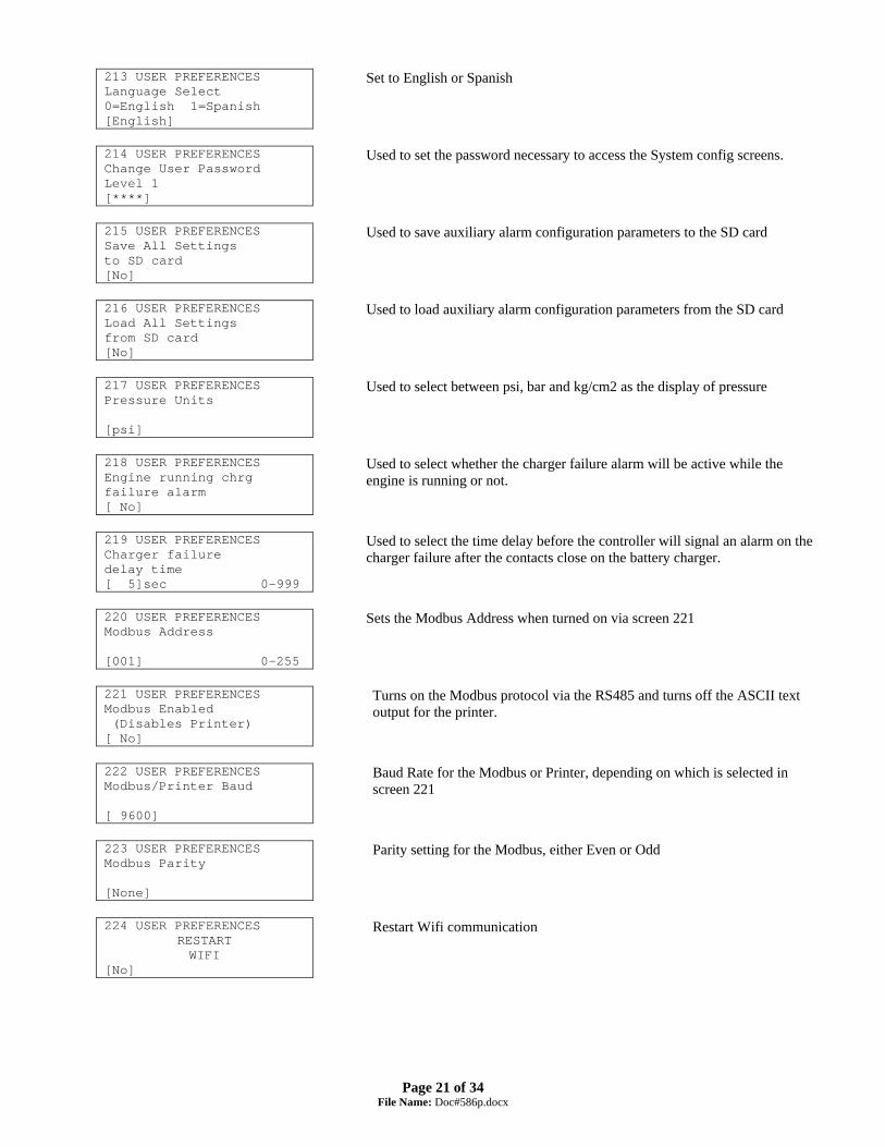
213 USER PREFERENCES Language Select 0=English 1=Spanish [English]
Set to English or Spanish
214 USER PREFERENCES Change User Password Level 1 [****]
Used to set the password necessary to access the System config screens.
215 USER PREFERENCES Save All Settings to SD card [No]
Used to save auxiliary alarm configuration parameters to the SD card
216 USER PREFERENCES Load All Settings from SD card [No]
Used to load auxiliary alarm configuration parameters from the SD card
217 USER PREFERENCES Pressure Units [psi]
Used to select between psi, bar and kg/cm2 as the display of pressure
218 USER PREFERENCES Engine running chrg failure alarm [ No]
Used to select whether the charger failure alarm will be active while the engine is running or not.
219 USER PREFERENCES Charger failure delay time [ 5]sec 0-999
Used to select the time delay before the controller will signal an alarm on the charger failure after the contacts close on the battery charger.
220 USER PREFERENCES Modbus Address [001] 0-255
Sets the Modbus Address when turned on via screen 221
221 USER PREFERENCES Modbus Enabled (Disables Printer) [ No]
Turns on the Modbus protocol via the RS485 and turns off the ASCII text output for the printer.
222 USER PREFERENCES Modbus/Printer Baud [ 9600]
Baud Rate for the Modbus or Printer, depending on which is selected in screen 221
223 USER PREFERENCES Modbus Parity [None]
Parity setting for the Modbus, either Even or Odd
224 USER PREFERENCES
RESTART WIFI
[No]
Restart Wifi communication
Page 22 of 34
File Name: Doc#586p.docx
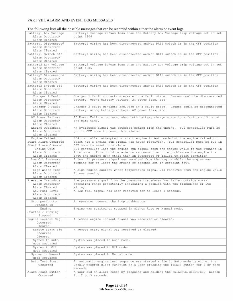
PART VIII: ALARM AND EVENT LOG MESSAGES
The following lists all the possible messages that can be recorded within either the alarm or event logs. Battery1 Low Voltage Alarm Occurred/ Alarm Cleared
Battery1 voltage is/was less than the Battery Low Voltage trip voltage set in set point #306
Battery1 Disconnectd Alarm Occurred/ Alarm Cleared
Battery1 wiring has been disconnected and/or BAT1 switch is in the OFF position
Battery1 Switch off Alarm Occurred/ Alarm Cleared
Battery1 wiring has been disconnected and/or BAT1 switch is in the OFF position
Battery2 Low Voltage Alarm Occurred/ Alarm Cleared
Battery2 voltage is/was less than the Battery Low Voltage trip voltage set in set point #306
Battery2 Disconnectd Alarm Occurred/ Alarm Cleared
Battery2 wiring has been disconnected and/or BAT2 switch is in the OFF position
Battery2 Switch off Alarm Occurred/ Alarm Cleared
Battery2 wiring has been disconnected and/or BAT2 switch is in the OFF position
Charger 1 Fault Alarm Occurred/ Alarm Cleared
Charger 1 fault contacts are/were in a fault state. Causes could be disconnected battery, wrong battery voltage, AC power loss, etc.
Charger 2 Fault Alarm Occurred/ Alarm Cleared
Charger 2 fault contacts are/were in a fault state. Causes could be disconnected battery, wrong battery voltage, AC power loss, etc.
AC Power Failure Alarm Occurred/ Alarm Cleared
AC Power Failure declared when both battery chargers are in a fault condition at the same time.
Engine Overspeed Alarm Occurred/ Alarm Cleared
An overspeed signal was detected coming from the engine. FD4 controller must be put in OFF mode to reset this alarm.
Engine Failed to Start Alarm Occurred Start Alarm Cleared
FD4 controller attempted to start engine in Auto mode but the engine failed to start (ie a engine run signal was never received). FD4 controller must be put in OFF mode to reset this alarm.
Engine Quit Alarm Occurred/ Alarm Cleared
FD4 controller lost the engine run signal from the engine while it was running in Auto mode. This could be a bad wire connection or a problem on the engine that shut the engine down other than an overspeed or failed to start condition.
Low Oil Pressure Alarm Occurred/ Alarm Cleared
A low oil pressure signal was received from the engine while the engine was running for at least the amount of seconds set in setpoint #304.
High Water Temp Alarm Occurred/ Alarm Cleared
A high engine coolant water temperature signal was received from the engine while it was running.
Pressure Transducer Alarm Occurred/ Alarm Cleared
The pressure signal from the pressure transducer has fallen outside normal operating range potentially indicating a problem with the transducer or its wiring.
Low Fuel Level Alarm Occurred/ Alarm Cleared
A low fuel signal has been received for at least 3 seconds.
Stop pushbutton Pressed in
An operator pressed the Stop pushbutton.
Engine Started / running Stopped
Engine was started or stopped in either Auto or Manual mode.
Engine Lockout Sig Occurred Cleared
A remote engine lockout signal was received or cleared.
Remote Start Sig Occurred Cleared
A remote start signal was received or cleared.
System in Auto Mode Occurred
System was placed in Auto mode.
System in Off Mode Occurred
System was placed in Off mode.
System in Manual Mode Occurred
System was placed in Manual mode.
Auto Test Start Occurred
An automatic engine test sequence was started while in Auto mode by either the weekly program clock function or a user pressing the [TEST] button for 2 or more seconds
Alarm Reset Button Occurred
A user did an alarm reset by pressing and holding the [SILENCE/RESET/ESC] button for 2 to 5 seconds.

Page 23 of 34
File Name: Doc#586p.docx
Low Pressure Start Occurred Cleared
A low pressure start was attempted because of a low pressure reading from the transducer or optional pressure switch while in Auto mode.
Low Press Condition Occurred Cleared
System pressure dropped below the start pressure or the optional pressure switch indicates a low pressure condition. This can be logged in all modes of operation.
Deluge Start Occurred Cleared
A deluge start signal was received while in Auto mode.
Controller Reboot Occurred
DC power was restored to the FD4 microprocessor.
Pressure Drop Occurred Cleared
If setpoint #204 is set to yes, this event gets recorded when the system pressure drops below the setting in setpoint #205.
Low Intake Pressure Shutdown Occurred Shutdown Cleared
If the low intake shutdown option is enabled in setpoint #116, a low suction signal will stop the engine.
Auxiliary Alarm Occurred Cleared
Indicates one of the aux alarms occurred as programmed in the user programs and was set to record in the event or alarm log but the text message assigned was 0. See Aux Alarm Text List Messages below for possible auxiliary alarm messages.

Page 24 of 34
File Name: Doc#586p.docx
Internal and External variables Aux Alarm Text List Messages
0 Auxiliary Alarm 1 High Fuel Level 2 Fuel Spill 3 Fuel Tank Rupture 4 Low Pump Room Temp 5 Reservoir Low 6 Reservoir Empty 7 Reservoir High 8 Flow Meter On 9 Relief Valve Open 10 Low Suction Pressure 11 High Engine Oil Temp 12 Low Jacket Water Flw 13 Low Jacket Water Lvl 14 Low Hydraulic Press 15 Low Firewater Press 16 Air Damper Closed 17 Air Damper Open 18 Alternator Fault 19 Low Gear Oil Press 20 Low Coolant Level 21 High Gear Oil Temp 22 Start Motor Fault 23 Low Fuel Pressure 24 Pump On Demand 25 High Exhaust Temp 26 High Fuel Temp 27 Pump Room Ajar 28 ECM Alternate 29 ECM Failure 30 High System Pressure 31 Dump Valve 32 User Alarm Text
List of possible internal variables used as inputs for aux alarm user programs. 30 Low Oil Pressure 31 General Battery Fault 32 Engine Quit Alarm 33 Pressure Transducer Fault 34 Low Intake Shutdown Alarm 35 Pump On Demand, Fire Condition 36 System Fault 37 Auto Mode 38 Manual Mode 39 Off Mode 40 Overspeed 41 Failed to Start 42 High Water Temp 43 AC Power Failure 44 Batt 1 Failure 45 Batt 2 Failure 46 Charger 1 Failure 47 Charger 2 Failure 48 General Charger Failure 49 Low Fuel Level 50 Pressure Drop Event 51 High System Pressure 52 Low Pressure 53 Engine Auto Available 54 Contactor Coil Failure 55 Test Mode 56 Hi Zone/Low Zone Mode 57 Contactor Coil 1 Failure 58 Contactor Coil 2 Failure 59 Engine running 60 Weekly Test Due 61 Dump Valve 62 Engine Lockout Latched 63 Start pressure fault 64 SD Card not present 65 SD Card logging fault 66 Cooling loop solenoid on 67 Local Alarm horn on 68 Started by Remote 69 Crank timer operating 70 Engine fault
Page 25 of 34
File Name: Doc#586p.docx
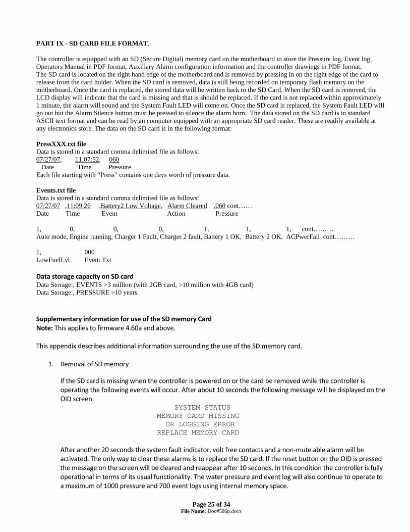
PART IX - SD CARD FILE FORMAT. The controller is equipped with an SD (Secure Digital) memory card on the motherboard to store the Pressure log, Event log, Operators Manual in PDF format, Auxiliary Alarm configuration information and the controller drawings in PDF format. The SD card is located on the right hand edge of the motherboard and is removed by pressing in on the right edge of the card to release from the card holder. When the SD card is removed, data is still being recorded on temporary flash memory on the motherboard. Once the card is replaced, the stored data will be written back to the SD Card. When the SD card is removed, the LCD display will indicate that the card is missing and that is should be replaced. If the card is not replaced within approximately 1 minute, the alarm will sound and the System Fault LED will come on. Once the SD card is replaced, the System Fault LED will go out but the Alarm Silence button must be pressed to silence the alarm horn. The data stored on the SD card is in standard ASCII text format and can be read by an computer equipped with an appropriate SD card reader. These are readily available at any electronics store. The data on the SD card is in the following format: PressXXX.txt file Data is stored in a standard comma delimited file as follows: 07/27/07, 11:07:52, 060 Date Time Pressure Each file starting with “Press” contains one days worth of pressure data. Events.txt file Data is stored in a standard comma delimited file as follows: 07/27/07 ,11:09:26 ,Battery2 Low Voltage, Alarm Cleared ,060 cont…… Date Time Event Action Pressure 1, 0, 0, 0, 1, 1, 1, cont……… Auto mode, Engine running, Charger 1 Fault, Charger 2 fault, Battery 1 OK, Battery 2 OK, ACPwerFail cont……… 1, 000 LowFuelLvl Event Txt Data storage capacity on SD card Data Storage:, EVENTS >3 million (with 2GB card, >10 million with 4GB card) Data Storage:, PRESSURE >10 years Supplementary information for use of the SD memory Card Note: This applies to firmware 4.60a and above. This appendix describes additional information surrounding the use of the SD memory card.
1. Removal of SD memory If the SD card is missing when the controller is powered on or the card be removed while the controller is operating the following events will occur. After about 10 seconds the following message will be displayed on the OID screen.
SYSTEM STATUS MEMORY CARD MISSING OR LOGGING ERROR REPLACE MEMORY CARD
After another 20 seconds the system fault indicator, volt free contacts and a non‐mute able alarm will be activated. The only way to clear these alarms is to replace the SD card. If the reset button on the OID is pressed the message on the screen will be cleared and reappear after 10 seconds. In this condition the controller is fully operational in terms of its usual functionality. The water pressure and event log will also continue to operate to a maximum of 1000 pressure and 700 event logs using internal memory space.

Page 26 of 34
File Name: Doc#586p.docx
If the original SD memory card is no longer available a blank SD memory card (formatted to FAT) can be used. The firmware of the controller will create the necessary log files and will continue to operate. When the new SD memory card is inserted all of the events and pressure logs that were missed will be automatically copied from the internally memory to the new SD memory card. As the logs are copying to the SD card the OID will display the follow message.
PLEASE WAIT.... CAPTURING UNSAVED EVENT LOGS 13 PRESSURE LOGS 159
After the controller has finished copying the logs stored internally to the SD card the alarms will be cleared. This operation can take a few seconds up to many minutes depending on the quantity of logs to copy and the speed of the SD card.
2. SD Logging Error The controller can detect problems logging to the SD card. If there is a logging error the panel behaves in the same way as when the SD card is removed. The only difference is that the SD card will still be in the control panel. The controller will periodically try to recover from logging errors and if successful the alarms and message on the OID will clear. However, if the message on the OID continues to display for over 15 minutes the SD card should be replaced with a new card or the old card can be reformatted to FAT (not FAT32 or exFAT) using a PC. It is recommended that any files that are readable from a PC are copied before the card is reformatted.
3. Description of the files stored on the SD memory card
Filename Description EVENTS.TXT The main log file. Contains a maximum of 3000 events occurred on the controller in date order. After
the 3000 limit is reached the oldest events will be overwritten from the top of the file. FD4FW.HEX Original firmware, Metron Eledyne use only. FW_DEF.TXT A file containing the version number of the FD4FW.HEX firmware file. Metron Eledyne use only. SETTINGS.TXT This file is created when ‘save all settings’ is executed from the controller, contains the saved settings. SCREENS.NEW Data file used for the screen messages on the OID, Metron Eledyne use only. MISCTEXT.NEW Data file used for the messages on the OID screens, Metron Eledyne use only. AUXALM.TXT Obsolete. Replaced by SETTING.TXT but may still be on the SD card. CONFIG.TXT Configures the LEDs on the OID, Metron Eledyne use only. PRESS**.TXT Contains the pressure log where ** is the day of month 01 through 31. Each month will overwrite the
previous month’s data day by day. At the start of each matching day number the old file is deleted and a new file recreated.
The SD card may contain other files. Normally these would be drawings or other documents in PDF format. See Part IX above for a description of the format of the pressure and event log files.

Page 27 of 34
File Name: Doc#586p.docx
Enhanced Data Logging Pressure Logging:
When it is time to log the pressure the system tries opens a pressure log file with a number at the end that corresponds with the day of the month. If the file doesn’t exist it just creates it and logs the pressure. If the file does exist it reads the first record to see if the month matches the current month. If it does match the pressure is logged at the end of the file if not the file is archived based on the date of the first record in the file. A new file is open and the pressure is logged. LOGSyy\PRESmmdd.TXT for the pressure log file.
Events Logging:
And LOGSyy\mmddhhMM.TXT for the events file.

Page 28 of 34
File Name: Doc#586p.docx
FD4 SD Card Compatibility Chart:
Make Model Type Speed Size Price(£)
(01‐Aug‐13) Date
Result FW Update
SanDisk SDSDB‐002G‐B35
SD
2
2gb
4.50
05‐Aug‐13
Pass
Pass
SanDisk SDSDB‐004G‐B35 SDHC 4 4gb 3.73 05‐Aug‐13 Pass Pass
SanDisk SDSDB‐008G‐B35 SDHC 4 8gb 4.58 05‐Aug‐13 Pass Pass
Sony SF‐4N4/T1 SDHC 4 4gb 3.74 05‐Aug‐13 Pass Pass
Transcend TS16GSDHC4 SDHC 4 16gb 6.65 05‐Aug‐13 Pass Pass
Kingston SD4/4GB SDHC 4 4gb 3.74 07‐Aug‐13 Pass Pass
Kingston SD4/8GB SDHC 4 8gb 3.33 07‐Aug‐13 Pass Pass
Transcend TS8GSDHC4 SDHC 4 8gb 4.32 07‐Aug‐13 Pass Pass
Kingston SD10V/8GB SDHC 10 8gb 4.99 07‐Aug‐13 Pass Pass
Lexar LSD8GBABEUCL6 SDHC 6 8gb 4.25 07‐Aug‐13 Pass Pass
Transcend TS32GSDHC4 SDHC 4 32gb 12.49 07‐Aug‐13 Pass Pass

Page 29 of 34
File Name: Doc#586p.docx
Appendix A
RS485 Port Usage For Serial Modbus RTU protocol: The Modbus option on the fire pump controller boards can be enabled by disabling the printer option to the onboard RS485 port. All communications to this port will be in a 2 wire RS485 format. 255 controllers can communicate on a single network. The pinout cabling required for connection to the port is as follows. It is necessary to apply a terminating resistor to both ends of the network. Note-Only 50 Modbus registers can be polled at time from the controller. I/O servers must be set up accordingly. Modbus Setup From Controller Interface: From the 200 series user preference configuration screens the Modbus setting can be access from screens 220 through 223. Screen 220 is used to set the Modbus address 1-255. All Modbus devices on a network must have a unique address. Screen 221 is used to enable/disable the Modbus option. If ‘Yes’ is selected the Modbus will be enabled and the RS485 port can no longer be used as a printer port. Screen 222 is used to set the baud rate for the RS485 port. The baud rates possible are 2400, 4800, 9600, 19200, and 38400 bits/second. Note that the baud rate setting is for the RS485 port in general and applies for Modbus and printer usage. Screen 223 is used to set the Modbus parity. Valid selections are ‘Even’, ‘Odd’, and ‘None’. This setting must match the parity setting of all other Modbus devices on the network. Modbus Register Usage Description: The historical event and pressure logs, and real time clock can be accessed and controlled through the Modbus registers listed below. Register 40001 is a write to controller only register where commands can be entered to accomplish the following as seen in figure 1.1. Depending on the Modbus I/O server used, either the individual bits in register 40001 can be toggled or integer values can be written. Either way, the controller automatically zeros register 40001 after a valid command is received.
Figure 1.1
Description Modbus Registers Usage Notes For Read/Write RegistersSet Real Time Clock 040001:0 Bit 0 Of Modbus Register 040001 - Must Write a 1 Into Register 040001 To Set ClockRemote Start Diesel Engine 040001:1 Bit 1 Of Modbus Register 040001 - Must Write a 2 Into Register 040001 To Start Engine
040001:2Increment Event Historical Log Data 040001:3 Bit 3 Of Modbus Register 040001 - Must Write an 8 Into Register 040001 To Increment Event Historical Log PointerDecrement Event Historical Log Data 040001:4 Bit 4 Of Modbus Register 040001 - Must Write a 16 Into Register 040001 To Decrement Event Historical Log PointerIncrement PSI Historical Log Data 040001:5 Bit 5 Of Modbus Register 040001 - Must Write a 32 Into Register 040001 To Increment PSI Historical Log PointerDecrement PSI Historical Log Data 040001:6 Bit 6 Of Modbus Register 040001 - Must Write a 64 Into Register 040001 To Decrement PSI Historical Log PointerSet Historical Event Log To Most Current Record 040001:7 Bit 7 Of Modbus Register 040001 - Must Write a 128 Into Register 040001 To Set Event Historical Log To Most Current RecordSet Historical PSI Log To Most Current Record 040001:8 Bit 8 Of Modbus Register 040001 - Must Write a 256 Into Register 040001 To Set PSI Historical Log To Most Current Record

Page 30 of 34
File Name: Doc#586p.docx
Real Time Event Monitoring: All events listed below in figure 1.2 are real time and can be viewed in Modbus register 40002. Figure 1.2 depicts the 16 bit breakdown and cross reference. This is not to be confused with the historical event log.
Figure 1.2
Description Modbus Registers Usage Notes For Read Only RegistersBit 0 'Switch In Auto' 040002:0 Bit 0 Of Modbus Register 040002 - Indicates the 'Switch In Auto' EventBit 1 'System Fault' 040002:1 Bit 1 Of Modbus Register 040002 - Indicates The 'System Fault' EventBit 2 'Engine Running' 040002:2 Bit 2 Of Modbus Register 040002 - Indicates The 'Engine Running' EventBit 3 'Battery Fault' 040002:3 Bit 3 Of Modbus Register 040002 - Indicates The 'Batter Fault' EventBit 4 'Charger Failure' 040002:4 Bit 4 Of Modbus Register 040002 - Indicates The ''Charger Failure' EventBit 5 'Failed To Start' 040002:5 Bit 5 Of Modbus Register 040002 - Indicates The 'Failed To Start' EventBit 6 'AC Power Failure' 040002:6 Bit 6 Of Modbus Register 040002 - Indicates The 'AC Power Failure' EventBit 7 'Low Oil Pressure' 040002:7 Bit 7 Of Modbus Register 040002 - Indicates the 'Low Oil Pressure' EventBit 8 'High Water Temperature' 040002:8 Bit 8 Of Modbus Register 040002 - Indicates The 'High Water Temperature' EventBit 9 'Low Fuel Level' 040002:9 Bit 9 Of Modbus Register 040002 - Indicates The 'Low Fuel Level' EventBit 10 'Pump On Demand' 040002:10 Bit 10 Of Modbus Register 040002 - Indicates The 'Pump On Demand' EventBit 11 'Engine Overspeed' 040002:11 Bit 11 Of Modbus Register 040002 - Indicates The 'Engine Overspeed' EventBit 12 'Engine Quit' 040002:12 Bit 12 Of Modbus Register 040002 - Indicates The 'Engine Quit' EventBit 13 'Low Discharge Pressure' 040002:13 Bit 13 Of Modbus Register 040002 - Indicates A 'Low Discharge Pressure' EventBit 14 'Engine Fuel Solenoid On' 040002:14 Bit 14 Of Modbus Register 040002 - Indicates A 'Engine Fuel Solenoid On' EventBit 15 'High Discharge Pressure' 040002:15 Bit 15 Of Modbus Register 040002 - Indicates A 'High Discharge Pressure' Event
**All Data In Modbus Register 40002 Is Real Time**
Description Modbus Registers Usage Notes For Read Only RegistersBit 0 'Pressure Transducer Fault' 040003:0 Bit 0 Of Modbus Register 040003 - Indicates the 'Pressure Transducer Fault' EventBit 1 'Low Intake' 040003:1 Bit 1 Of Modbus Register 040003 - Indicates The 'Low Intake' EventBit 2 'Switch in Manual' 040003:2 Bit 2 Of Modbus Register 040003 - Indicates The 'Switch in Manual' EventBit 3 'Switch in Off' 040003:3 Bit 3 Of Modbus Register 040003 - Indicates 'Switch in Off' EventBit 4 'Battery 1 Failure' 040003:4 Bit 4 Of Modbus Register 040003 - Indicates The 'Battery 1 Failure' EventBit 5 'Battery 2 Failure' 040003:5 Bit 5 Of Modbus Register 040003 - Indicates The 'Battery 2 Failure' EventBit 6 'Charger 1 Failure' 040003:6 Bit 6 Of Modbus Register 040003 - Indicates The 'Charger 1 Failure' EventBit 7 'Charger 2 Failure' 040003:7 Bit 7 Of Modbus Register 040003 - Indicates The 'Charger 2 Failure' EventBit 8 'Pressure Drop' 040003:8 Bit 8 Of Modbus Register 040003 - Indicates The 'Pressure Drop' EventBit 9 'Engine Auto Available' 040003:9 Bit 9 Of Modbus Register 040003 - Indicates The 'Engine Auto Start Available' EventBit 10 'Contactor Coil Failure' 040003:10 Bit 10 Of Modbus Register 040003 - Indicates The 'Common Contactor Coil Failure' EventBit 11 'Test Running' 040003:11 Bit 11 Of Modbus Register 040003 - Indicates The 'Engine Running in Test Mode' EventBit 12 'Hi/Low Zone' 040003:12 Bit 12 Of Modbus Register 040003 - Indicates The 'High/Low Zone EventBit 13 'Contactor Coil 1 Failure' 040003:13 Bit 13 Of Modbus Register 040003 - Indicates A 'Contactor Coil 1 Failure' EventBit 14 'Contactor Coil 2 Failure' 040003:14 Bit 14 Of Modbus Register 040003 - Indicates A 'Contactor Coil 2 Failure' EventBit 15 'Weekly Test Due' 040003:15 Bit 15 Of Modbus Register 040003 - Indicates A 'Weekly Test Due' Event
**All Data In Modbus Register 40003 Is Real Time**
Description Modbus Registers Usage Notes For Read Only RegistersBit 0 'Dump Valve' 040004:0 Bit 0 Of Modbus Register 040004 - Indicates 'Dump Valve On' Event Bit 1 'Engine Lockout' 040004:1 Bit 1 Of Modbus Register 040004 - Indicates 'Engine Lockout' InputBit 2 'Stop Push button' 040004:2 Bit 2 Of Modbus Register 040004 - Indicates 'Stop push button pressed' Event Bit 3 'SD Card Missing' 040004:3 Bit 3 Of Modbus Register 040004 - Indicates ' SD Card Missing' EventBit 4 'Reset button' 040004:4 Bit 4 Of Modbus Register 040004 - Indicates 'Reset push button pressed' Event Bit 5 'OID LED 13' 040004:5 Bit 5 Of Modbus Register 040004 - Indicates 'OID Lamp 13 on'Bit 6 'OID LED 14' 040004:6 Bit 6 Of Modbus Register 040004 - Indicates 'OID Lamp 14 on'Bit 7 'OID LED 15' 040004:7 Bit 7 Of Modbus Register 040004 - Indicates 'OID Lamp 15 on/ECM Failure'Bit 8 'OID LED 16' 040004:8 Bit 8 Of Modbus Register 040004 - Indicates 'OID Lamp 16 on/EMC Warning'Bit 9 'OID LED 17' 040004:9 Bit 9 Of Modbus Register 040004 - Indicates 'OID Lamp 17 on/ECM Switch in Alt.'Bit 10 'OID LED 18' 040004:10 Bit 10 Of Modbus Register 040004 - Indicates 'OID Lamp 18 on/Fuel Injection Fault'Bit 11 'OID LED 19' 040004:11 Bit 11 Of Modbus Register 040004 - Indicates 'OID Lamp 19 on/Fual Tank Leak'Bit 12 'OID LED 20' 040004:12 Bit 12 Of Modbus Register 040004 - Indicates 'OID Lamp 20 on/Clogged Water Strainer'Bit 13 'OID LED 21' 040004:13 Bit 13 Of Modbus Register 040004 - Indicates 'OID Lamp 21 on/High Cooling Water Temp.'Bit 14 'OID LED 22' 040004:14 Bit 14 Of Modbus Register 040004 - Indicates 'OID Lamp 22 on/Low Engine Temp.'Bit 15 'OID LED 23' 040004:15 Bit 15 Of Modbus Register 040004 - Indicates 'OID Lamp 23 on/Contactor Coil Failure'
**All Data In Modbus Register 40004 Is Real Time**
Description Modbus Registers Usage Notes For Read Only RegistersBit 0 'R1' 040005:0 Bit 0 Of Modbus Register 040005 - Indicates 'Relay 1 On' Bit 1 'R2' 040005:1 Bit 1 Of Modbus Register 040005 - Indicates 'Relay 2 On' Bit 2 'R3' 040005:2 Bit 2 Of Modbus Register 040005 - Indicates 'Relay 3 On' Bit 3 'R4' 040005:3 Bit 3 Of Modbus Register 040005 - Indicates 'Relay 4 On' - Horn Bit 4 'R5' 040005:4 Bit 4 Of Modbus Register 040005 - Indicates ' Relay 5 On' - Drain SolenoidBit 5 'R6' 040005:5 Bit 5 Of Modbus Register 040005 - Indicates 'Relay 6 On' - Engine Fuel SolenoidBit 6 'R7' 040005:6 Bit 6 Of Modbus Register 040005 - Indicates 'Relay 7 On' - Engine Stop SolenoidBit 7 'R8' 040005:7 Bit 7 Of Modbus Register 040005 - Indicates 'Relay 8 On' Bit 8 'R9' 040005:8 Bit 8 Of Modbus Register 040005 - Indicates 'Relay 9 On' - System Fault (US mode)Bit 9 'R10' 040005:9 Bit 9 Of Modbus Register 040005 - Indicates 'Relay 10 On' - Engine Running (US mode)Bit 10 'R11' 040005:10 Bit 10 Of Modbus Register 040005 - Indicates 'Relay 11 On'Bit 11 'R12' 040005:11 Bit 11 Of Modbus Register 040005 - Indicates 'Relay 12 On' Auto mode on (EU Mode)Bit 12 'R13' 040005:12 Bit 12 Of Modbus Register 040005 - Indicates 'Relay 13 On' Bit 13 'R14' 040005:13 Bit 13 Of Modbus Register 040005 - Indicates 'Relay 14 On' Engine running (EU Mode)Bit 14 'R15' 040005:14 Bit 14 Of Modbus Register 040005 - Indicates 'Relay 15 On' Engine running (EU Mode)Bit 15 'R16' 040005:15 Bit 15 Of Modbus Register 040005 - Indicates 'Relay 16 On' Pump on demand (EU Mode)
**All Data In Modbus Register 040005 Is Real Time**
Description Modbus Registers Usage Notes For Read Only RegistersBit 0 'R17' 040006:0 Bit 0 Of Modbus Register 040006 - Indicates 'Relay 17 On' Failed to start (EU Mode)Bit 1 'R18' 040006:1 Bit 1 Of Modbus Register 040006 - Indicates 'Relay 18 On' System Fault (EU Mode)Bit 2 'R19' 040006:2 Bit 2 Of Modbus Register 040006 - Indicates 'Relay 19 On' Bit 3 'R20' 040006:3 Bit 3 Of Modbus Register 040006 - Indicates 'Relay 20 On' Bit 4 'R21' 040006:4 Bit 4 Of Modbus Register 040006 - Indicates ' Relay 21 On' Bit 5 'R22' 040006:5 Bit 5 Of Modbus Register 040006 - Indicates 'Relay 22 On' Bit 6 'R23' 040006:6 Bit 6 Of Modbus Register 040006 - Indicates 'Relay 23 On' Bit 7 'R24' 040006:7 Bit 7 Of Modbus Register 040006 - Indicates 'Relay 24 On' Bit 8 'Auto Test' 040006:8 Bit 8 Of Modbus Register 040006 - Indicates 'Test mode initiated but not running'Bit 9 'Cranking' 040006:9 Bit 9 Of Modbus Register 040006 - Indicates 'Cranking engine'Bit 10 'Start by remote' 040006:10 Bit 10 Of Modbus Register 040006 - Indicates 'Engine started running after remote start'Bit 11 'Remote Start Input' 040006:11 Bit 11 Of Modbus Register 040006 - Indicates 'Remote start input present'Bit 12 'Remote Start' 040006:12 Bit 12 Of Modbus Register 040006 - Indicates 'Remote start was received'Bit 13 'Shutdown in test' 040006:13 Bit 13 Of Modbus Register 040006 - Indicates 'Engine stopped during test run due to alarm'Bit 14 040006:14 Bit 14 Of Modbus Register 040006 - NOT USEDBit 15 040006:15 Bit 15 Of Modbus Register 040006 - NOT USED
**All Data In Modbus Register 040006 Is Real Time**

Page 31 of 34
File Name: Doc#586p.docx
Setting And Reading The Real Time Clock Through Modbus: Modbus registers 40007 through 400013 are real time clock read registers as seen in figure 1.3. To set the clock current values must be entered into registers 40014 through 40020. Any of these registers left to zero will result in an incorrect clock setting. Once desired clock date and time values are entered bit 0 of register 40001 must be toggled for the controller to accept the values. This can be done by setting bit 0 high or writing a 1 to register 40001. The controller will then accept the new values.
Figure 1.3 Miscellaneous Floating Point and Integer Readings: Battery voltage and amperage along with engine run hours, system pressure, system start pressure, time until start, time until stop and engine starts can all be read from the controller Real or Floating Point registers. These are Modbus registers 40021 through 40037. These registers are word or double word. All available floating point and integer registers are shown in Figure 1.4 and do not require scaling.
Figure 1.4 No more than 50 registers can be polled at a time. Historical Alarms and Events: The historical events and alarms can be viewed from Modbus registers 40107 through 40114. Here it is possible to scroll through the entire log and set the log pointer to the most current record. Register 40107 contains a number representing the actual log number entry location in the controller. Register 40108 contains a number representing the event or alarm that can be indexed using figures 1.6 through 1.9. Registers 40109 through 40114 show the date and time stamp information for the log record being pointed to. To maneuver through the log: Toggling bit 3 or writing an 8 to register 40001 will increment the log by one entry. Toggling bit 4 or writing a 16 to register 40001 will decrement the log by one entry. Toggling bit 7 or writing a 128 to register 40001 will set the log to view the most current log entry.
Description Modbus Registers Usage Notes For Read Only RegistersReal Time Clock Month 040007 PLC Read Real Time Clock Month 1-12Real Time Clock Day 040008 PLC Read Real Time Clock Day 1-31Real Time Clock Year 040009 PLC Read Real Time Clock Year 00-99Real Time Clock Hour 040010 PLC Read Real Time Clock Hour 1-24Real Time Clock Minute 040011 PLC Read Real Time Clock Minute 0-59Real Time Clock Second 040012 PLC Read Real Time Clock Seconds 0-59Real Time Clock Day Of Week 040013 PLC Read Real Time Clock Day Of Week 0-6 "Sunday = 0"
**Must Have All Fields Filled To Set PLC Clock, Null Fields Will Write 0's To The Clock****Once Desired Clock Values Are Entered, Toggling Bit 0 Of Modbus Register 040001 Or PLC Address V9001.0 Will Set Clock
Real Time Clock Set Month 040014 PLC Set Real Time Clock Month 1-12Real Time Clock Set Day 040015 PLC Set Real Time Clock Day 1-31Real Time Clock Set Year 040016 PLC Set Real Time Clock Year 00-99 "Cannot Enter 2006, Must Enter 06"Real Time Clock Set Hour 040017 PLC Set Real Time Clock Hour 1-24 Real Time Clock Set Minute 040018 PLC Set Real Time Clock Minute 0-59Real Time Clock Set Second 040019 PLC Set Real Time Clock Second 0-59Real Time Clock Set Day Of Week 040020 PLC Set Real Time Clock Day Of Week 0-6 "Sunday = 0"
Description Modbus Registers Usage Notes For Read Only RegistersBattery 1 Volts Reading 040021-040022 Battery 1 Volts Floating Point ValueBattery 2 Volts Reading 040023-040024 Battery 2 Volts Floating Point ValueBattery 1 Amps Reading 040025-040026 Battery 1 Amps Floating Point ValueBattery 2 Amps Reading 040027-040028 Battery 2 Amps Floating Point ValueEngine Run Hours 040029-040030 Engine Run Hours Floationg Point ValueSystem Pressure PSI 040031-040032 System Pressure 0-300 PSI Floating Point ValueStart Pressure PSI 040033-040034 Screen 101 Start Pressure 0-300 PSI Floating Point ValueTime Until Start 040035 Time Until Start Integer Value (Seconds)Time Until Stop 040036 Time Until Stop Integer Value (Seconds)Engine Starts 040037 Number of Engine Starts Integer Value

Page 32 of 34
File Name: Doc#586p.docx
It is recommended to set the log to the most current entry before scrolling. When scrolling, it is possible to move forward and backward through roughly a full weeks worth of data. See figure 1.5 for register interpretation.
Figure 1.5
Figure 1.6 Figure 1.7
Description Modbus Registers Usage Notes For Read Only RegistersEvent Historical Log Index 040107 Event Historical Log Index Value For Record Being Pointed ToEvent Historical Log Event Number 040108 Event Historical Log Event That Occurred 1-21Event Historical Log Event Month 040109 Event Historical Log Month Event Occured 1-12Event Historical Log Event Day 040110 Event Historical Log Day Event Occured 1-31Event Historical Log Event Year 040111 Event Historical Log Year Event Occurred 00-99Event Historical Log Event Hours 040112 Event Historical log Hour Event Occurred 1-24Event Historical Log Event Minutes 040113 Event Historical Log Minute Event Occurred 0-59Event Historical Log Event Seconds 040114 Event Historical Log Second Event Occurred 0-59
**Toggle Bit 3 Of Modbus Register 040001 Or PLC Address V9001.3 To Increment Historical Event Log Record 0-499****Toggle Bit 4 Of Modbus Register 040001 Or PLC Address V9001.4 To Decrement Historical Event Log Record 0-499****Toggle Bit 7 Of Modbus Register 040001 Or PLC Address V9001.7 To View Most Current Historical Event Log Record**
Event/Alarm Description Event Index #Battery 1 Low Voltage Alarm Occurred 0Battery 1 Low Voltage Alarm Cleared 1First-Up Reset Occurred 2First-Up Reset didn't Occur 3Silence Pressed Occurred 4Silence Pressed didn't Occurred 5Battery 2 Low Voltage Alarm Occurred 6Battery 2 Low Voltage Alarm Cleared 7SPARE 1 Alarm Occurred 8SPARE 1 Alarm Cleared 9SPARE 2 Alarm Occurred 10SPARE 2 Alarm Cleared 11Charger 1 Fault Alarm Occurred 12Charger 1 Fault Alarm Cleared 13Charger 2 Fault Alarm Occurred 14Charger 2 Fault Alarm Cleared 15AC Power Failure Alarm Occurred 16AC Power Failure Alarm Cleared 17Engine Overspeed Alarm Occurred 18Engine Overspeed Alarm Cleared 19Engine Failed To Start Alarm Occurred 20Engine Failed To Start Alarm Cleared 21Engine Quit Alarm Occurred 22Engine Quit Alarm Cleared 23Low Oil Pressure Alarm Occurred 24Low Oil Pressure Alarm Cleared 25High Water Temperature Alarm Occurred 26High Water Temperature Alarm Cleared 27Pressure Transducer Alarm Occurred 28Pressure Transducer Alarm Cleared 29Low Fuel Level Alarm Occurred 30Low Fuel Level Alarm Cleared 31Low Coolant Temp Occurred 32Low Coolant Temp Cleared 33High Coolant Temp Occurred 34High Coolant Temp Cleared 35Battery 1 Fault Contact Occurred 36Battery 1 Fault Contact Cleared 37Battery 2 Fault Contact Occurred 38Battery 2 Fault Contact Cleared 39Stop Pushbutton Pressed Event 40Stop Pushbutton Released Event 41
Event/Alarm Description Event Index #Engine Started/Running Event 42Engine Stopped Event 43Engine Overspeed Signal Occurred 44Engine Overspeed Signal Cleared 45Low Oil Pressure Signal Occurred 46Low Oil Pressure Signal Cleared 47High Water Temperature Signal Occurred 48High Water Temperature Signal Cleared 49Engine Lockout Signal Occurred 50Engine Lockout Signal Cleared 51Deluge Signal Occurred 52Deluge Signal Cleared 53Remote Start Signal Occurred 54Remote Start Signal Cleared 55Low Fuel Level Signal Occurred 56Low Fuel Level Signal Cleared 57Pressure Switch Signal Occurred 58Pressure Switch Signal Cleared 59Aux 2 Message Occurred 60Aux 2 Message Cleared 61Fuel Tank Leak Occurred 62Fuel Tank Leak Cleared 63Fuel Injector Fault Occurred 64Fuel Injector Fault Cleared 65ECM Switch Alt. Pos. Occurred 66ECM Switch Alt. Pos. Cleared 67EMC Warning Occurred 68EMC Warning Cleared 69EMC Failure Occurred 70EMC Failure Cleared 71Water Strainer Clog Occurred 72Water Strainer Clog Cleared 73Aux 9 Message Occurred 74Aux 9 Message Cleared 75Coil 1 failure Occurred 76Coil 1 failure Cleared 77Coil 2 failure Occurred 78Coil 2 failure Cleared 79System In Auto Event Occurred 80System In Auto Event Cleared 81System In Off Event Occurred 82System In Off Event Cleared 83System In Manual Event Occurred 84System In Manual Event Cleared 85

Page 33 of 34
File Name: Doc#586p.docx
Figure 1.8 Figure 1.9
Event/Alarm Description Event Index #Auto Test Start Event Occurred 86Auto Test Start Event Cleared 87Alarm Reset Button Pressed Event Occurred 88Alarm Reset Button Pressed Event Cleared 89Low Pressure Start Event Occurred 90Low Pressure Start Event Cleared 91Low Pressure Condition Event Occurred 92Low Pressure Condition Event Cleared 93Deluge Start Event Occurred 94Deluge Start Event Cleared 95Memory Card Missing Event Occurred 96Memory Card Missing Event Cleared 97Controller Reboot Event Occurred 98Controller Reboot Event Cleared 99Pressure Drop Event Occurred 100Pressure Drop Event Cleared 101N/A Unused Log Entry 102N/A Unused Log Entry 103N/A Invalid Alarm 104N/A Invalid Alarm 105Low Intake Pressure Shutdown Event Occurred 106Low Intake Pressure Shutdown Event Cleared 107Auxiliary Alarm Occurred 108Auxiliary Alarm Cleared 109High Fuel Level Alarm Occurred 110High Fuel Level Alarm Cleared 111Fuel Spill Alarm Occurred 112Fuel Spill Alarm Cleared 113Fuel Tank Rupture Alarm Occurred 114Fuel Tank Rupture Alarm Cleared 115Low Pump Room Temperature Alarm Occurred 116Low Pump Room Temperature Alarm Cleared 117Reservoir Low Alarm Occurred 118Reservoir Low Alarm Cleared 119Reservoir Empty Alarm Occurred 120Reservoir Empty Alarm Cleared 121Reservoir High Alarm Occurred 122Reservoir High Alarm Cleared 123Flow Meter On Alarm Occurred 124Flow Meter On Alarm Cleared 125Relief Valve Open Alarm Occurred 126Relief Valve Open Alarm Cleared 127Low Suction Pressure Alarm Occurred 128Low Suction Pressure Alarm Cleared 129
Event/Alarm Description Event Index #High Engine Oil Temperature Alarm Occurred 130High Engine Oil Temperature Alarm Cleared 131Low Jacket Water Flow Alarm Occurred 132Low Jacket Water Flow Alarm Cleared 133Low Jacket Water Level Alarm Occurred 134Low Jacket Water Level Alarm Cleared 135Low Hydraulic Pressure Alarm Occurred 136Low Hydraulic Pressure Alarm Cleared 137Low Firewater Pressure Alarm Occurred 138Low Firewater Pressure Alarm Cleared 139Air Damper Closed Alarm Occurred 140Air Damper Closed Alarm Cleared 141Air Damper Open Alarm Occurred 142Air Damper Open Alarm Cleared 143Alternator Fault Occurred 144Alternator Fault Cleared 145Low Gear Oil Pressure Alarm Occurred 146Low Gear Oil Pressure Alarm Cleared 147Low Coolant Level Alarm Occurred 148Low Coolant Level Alarm Cleared 149High Gear Oil Temperature Alarm Occurred 150High Gear Oil Temperature Alarm Cleared 151Starter Motor Fault Occurred 152Starter Motor Fault Cleared 153Low Fuel Pressure Alarm Occurred 154Low Fuel Pressure Alarm Cleared 155Pump On Demand Alarm Occurred 156Pump On Demand Alarm Cleared 157High Exhaust Temperature Alarm Occurred 158High Exhaust Temperature Alarm Cleared 159High Fuel Temperature Alarm Occurred 160High Fuel Temperature Alarm Cleared 161Pump Room Door Ajar Alarm Occurred 162Pump Room Door Ajar Alarm Cleared 163ECM Alternate Alarm Occurred 164ECM Alternate Alarm Cleared 165ECM Failure Occurred 166ECM Failure Cleared 167High System Pressure Alarm Occurred 168High System Pressure Alarm Cleared 169Dump Valve Occurred 170Dump Valve Cleared 171User Alarm Text Occurred 172User Alarm Text Cleared 173Stop Pressure Fault Occurred 174Stop Pressure Fault Cleared 175

Page 34 of 34
File Name: Doc#586p.docx
Historical Pressure Readings: The historical pressure readings can be viewed from Modbus registers 40122 through 40129. Here it is possible to scroll through the entire log and set the log pointer to the most current record. Register 40122 contains a number representing the actual log number entry location in the controller. Register 40123 contains a number representing the logged pressure reading. Registers 40124 through 40129 show the date and time stamp information for the log record being pointed to. To maneuver through the log: Toggling bit 5 or writing a 32 to register 40001 will increment the log by one entry. Toggling bit 6 or writing a 64 to register 40001 will decrement the log by one entry. Toggling bit 8 or writing a 256 to register 40001 will set the log to view the most current log entry. It is recommended to set the log to the most current entry before scrolling. When scrolling, it is possible to move forward and backward through roughly a full weeks worth of data. See figure 1.10 for register interpretation.
Figure 1.10
Description Modbus Registers Usage Notes For Read Only RegistersPSI Historical Log Index 040122 PSI Historical Log Index Value For Record Being Pointed ToPSI Historical Log Pressure 040123 PSI Historical Log PSI That Occurred 0-300 PSIPSI Historical Log Day 040124 PSI Historical Log Day PSI Occured 1-12PSI Historical Log Month 040125 PSI Historical Log Month PSI Occured 1-31PSI Historical Log Year 040126 PSI Historical Log Year PSI Occurred 00-99PSI Historical Log Hours 040127 PSI Historical Log Hour PSI Occurred 1-24PSI Historical Log Minutes 040128 PSI Historical Log Minute PSI Occurred 0-59PSI Historical Log Seconds 040129 PSI Historical Log Second PSI Occurred 0-59
**Toggle Bit 5 Of Modbus Register 040001 Or PLC Address V9001.5 To Increment PSI Historical Log Record 0-499****Toggle Bit 6 Of Modbus Register 040001 Or PLC Address V9001.6 To Decrement PSI Historical Log Record 0-499****Toggle Bit 8 Of Modbus Register 040001 Or PLC Address V9000.8 To View Most Current Historical PSI Log Record**