TM 9-2330-397-14P M1112 TRAILER, TANK, WATER 400 GALLON PART 4
����� �����
���
������� �� � �� �
��� ����� ����� �������
C33907001SE_00 � Copyright Nokia Networks Oy
M1112ADSL (over ISDN) Router
Administrator Manual
C33907.20 A0
M1112 Administrator Manual
� Copyright Nokia Networks Oy C33907001SE_00ii
� COPYRIGHT Nokia Networks Oy 2000All rights reserved.No part of this publication may be copied, distributed, transmitted, transcribed, stored in a retrievalsystem, or translated into any human or computer language without the prior written permissionof Nokia Networks Oy.
The manufacturer has made every effort to ensure that the instructions contained in thedocuments are adequate and free of errors and omissions. The manufacturer will, if necessary,explain issues which may not be covered by the documents. The manufacturer’s liability for anyerrors in the documents is limited to the correction of errors and the aforementioned advisoryservices.
The documents have been prepared to be used by professional and properly trained personnel,and the customer assumes full responsibility when using them.The manufacturer welcomescustomer comments as part of the process of continual development and improvement of thedocumentation in the best way possible from the user’s viewpoint. Please submit your commentsto the nearest Nokia sales representative.
NOKIA is a registered trademark of Nokia Corporation.
Any other trademarks mentioned in the documents are the property of their respective owners.

� Copyright Nokia Networks OyC33907001SE_00 iii
Document HistoryDocument Date Comment
C33907001SE_00 13.09.2000

M1112 Administrator Manual
� Copyright Nokia Networks Oy C33907001SE_00iv
� Copyright Nokia Networks OyC33907001SE_00 v
Contents
Chapter 1Introduction to Nokia M1112 1-1. . . . . . . . . . . . . . . . . .
Chapter 2Applications and features 2-1. . . . . . . . . . . . . . . . . . . . . 2.1 Applications 2-1. . . . . . . . . . . . . . . . . . . . . . . . . . . . . . . . . . . .
Internet access 2-1. . . . . . . . . . . . . . . . . . . . . . . . . . . . . . . . . Remote work 2-3. . . . . . . . . . . . . . . . . . . . . . . . . . . . . . . . . . LAN interconnection 2-4. . . . . . . . . . . . . . . . . . . . . . . . . . . .
2.2 Features 2-4. . . . . . . . . . . . . . . . . . . . . . . . . . . . . . . . . . . . . . . 2.2.1 Interfaces 2-4. . . . . . . . . . . . . . . . . . . . . . . . . . . . . . . . . . . . . . .
LAN interface 2-6. . . . . . . . . . . . . . . . . . . . . . . . . . . . . . . . . Internal host/gateway interface 2-7. . . . . . . . . . . . . . . . . . . . Data VCC operation 2-7. . . . . . . . . . . . . . . . . . . . . . . . . . . .
2.2.2 Routing 2-7. . . . . . . . . . . . . . . . . . . . . . . . . . . . . . . . . . . . . . . . 2.2.3 Bridging 2-7. . . . . . . . . . . . . . . . . . . . . . . . . . . . . . . . . . . . . . . . 2.2.4 Network Address Port Translation 2-8. . . . . . . . . . . . . . . . . . . 2.2.5 Dynamic Host Configuration Protocol 2-9. . . . . . . . . . . . . . . . 2.2.6 ATM and ADSL 2-9. . . . . . . . . . . . . . . . . . . . . . . . . . . . . . . . . . 2.2.7 Point-to-Point Tunneling Protocol (PPTP) 2-10. . . . . . . . . . . . . 2.2.8 Point-to-Point Protocol over Ethernet (PPPoE) 2-11. . . . . . . . . . 2.2.9 Payload encapsulations 2-11. . . . . . . . . . . . . . . . . . . . . . . . . . . . 2.2.10 Weighted Fair Queueing (Class of Service) 2-11. . . . . . . . . . . . 2.2.11 Management 2-12. . . . . . . . . . . . . . . . . . . . . . . . . . . . . . . . . . . . 2.2.12 Dedicated management channel 2-12. . . . . . . . . . . . . . . . . . . . .
M1112 Administrator Manual
� Copyright Nokia Networks Oy C33907001SE_00vi
Chapter 3Interfaces and indicator lights 3-1. . . . . . . . . . . . . . . . . 3.1 Interfaces 3-1. . . . . . . . . . . . . . . . . . . . . . . . . . . . . . . . . . . . . . 3.1.1 Ethernet interface 3-2. . . . . . . . . . . . . . . . . . . . . . . . . . . . . . . . . 3.1.2 ADSL interface 3-2. . . . . . . . . . . . . . . . . . . . . . . . . . . . . . . . . .
3.2 Command line interface 3-3. . . . . . . . . . . . . . . . . . . . . . . . . .
3.3 Indicator lights 3-4. . . . . . . . . . . . . . . . . . . . . . . . . . . . . . . . . .
Chapter 4Installing Nokia M1112 4-1. . . . . . . . . . . . . . . . . . . . . . . 4.1 M1112 default settings 4-1. . . . . . . . . . . . . . . . . . . . . . . . . . . .
4.2 Step-by-step installation procedure 4-3. . . . . . . . . . . . . . . . .
Chapter 5Managing M1112 5-1. . . . . . . . . . . . . . . . . . . . . . . . . . . . 5.1 Operational examples 5-1. . . . . . . . . . . . . . . . . . . . . . . . . . . . 5.1.1 Routing/tunneling IP only 5-2. . . . . . . . . . . . . . . . . . . . . . . . . . 5.1.2 Routing/tunneling IP, bridging other protocols 5-2. . . . . . . . . . 5.1.3 Routing/tunneling IP, bridging all protocols including IP 5-3. . 5.1.4 Bridging only 5-4. . . . . . . . . . . . . . . . . . . . . . . . . . . . . . . . . . . .
5.2 Typical configuration tasks 5-4. . . . . . . . . . . . . . . . . . . . . . . . 5.2.1 Configuring DHCP and DNS 5-4. . . . . . . . . . . . . . . . . . . . . . . 5.2.2 Configuring static and dynamic routing 5-5. . . . . . . . . . . . . . . 5.2.3 File system and downloading new firmware using TFTP 5-6. .
Downloading configuration or application from monitor 5-7
5.3 Browser management 5-8. . . . . . . . . . . . . . . . . . . . . . . . . . . . 5.3.1 Opening a connection 5-9. . . . . . . . . . . . . . . . . . . . . . . . . . . . . 5.3.2 Main Page 5-10. . . . . . . . . . . . . . . . . . . . . . . . . . . . . . . . . . . . . . 5.3.3 Service Providers pages 5-11. . . . . . . . . . . . . . . . . . . . . . . . . . . . 5.3.4 Local Network pages 5-13. . . . . . . . . . . . . . . . . . . . . . . . . . . . . .
Local ports 5-13. . . . . . . . . . . . . . . . . . . . . . . . . . . . . . . . . . . . DHCP 5-13. . . . . . . . . . . . . . . . . . . . . . . . . . . . . . . . . . . . . . . . NAPT 5-16. . . . . . . . . . . . . . . . . . . . . . . . . . . . . . . . . . . . . . . . Routing page 5-17. . . . . . . . . . . . . . . . . . . . . . . . . . . . . . . . . .
5.3.5 Statistics page 5-18. . . . . . . . . . . . . . . . . . . . . . . . . . . . . . . . . . . 5.3.6 Restart page 5-19. . . . . . . . . . . . . . . . . . . . . . . . . . . . . . . . . . . . . 5.3.7 Save Config page 5-20. . . . . . . . . . . . . . . . . . . . . . . . . . . . . . . . .
� Copyright Nokia Networks OyC33907001SE_00 vii
5.4 Command line interface (CLI) 5-20. . . . . . . . . . . . . . . . . . . . . 5.4.1 Main mode commands 5-23. . . . . . . . . . . . . . . . . . . . . . . . . . . . 5.4.2 Configuration mode commands 5-44. . . . . . . . . . . . . . . . . . . . . .
Root level commands 5-45. . . . . . . . . . . . . . . . . . . . . . . . . . . System level commands 5-46. . . . . . . . . . . . . . . . . . . . . . . . . Password level command 5-47. . . . . . . . . . . . . . . . . . . . . . . . Ethernet level commands 5-48. . . . . . . . . . . . . . . . . . . . . . . . VCC (ATM channel) commands 5-50. . . . . . . . . . . . . . . . . . . Vbridge commands 5-55. . . . . . . . . . . . . . . . . . . . . . . . . . . . . Dedicated management channel commands 5-56. . . . . . . . . . Common commands 5-57. . . . . . . . . . . . . . . . . . . . . . . . . . . .
Appendix ATechnical specifications A-1. . . . . . . . . . . . . . . . . . . . . . . A.1 Mechanical construction and power supply A-3. . . . . . . . . .
A.2 Ambient conditions, EMC and safety A-3. . . . . . . . . . . . . . . Ambient conditions A-3. . . . . . . . . . . . . . . . . . . . . . . . . . . . . EMC A-3. . . . . . . . . . . . . . . . . . . . . . . . . . . . . . . . . . . . . . . . . Safety A-4. . . . . . . . . . . . . . . . . . . . . . . . . . . . . . . . . . . . . . . .
Glossary

M1112 Administrator Manual
� Copyright Nokia Networks Oy C33907001SE_00viii
Introduction to Nokia M1112
� Copyright Nokia Networks OyC33907001SE_00 1-1
Chapter 1Introduction to Nokia M1112
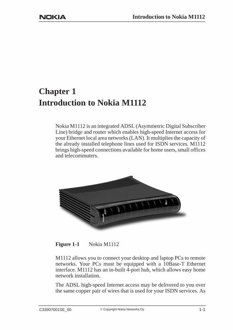
Nokia M1112 is an integrated ADSL (Asymmetric Digital SubscriberLine) bridge and router which enables high-speed Internet access foryour Ethernet local area networks (LAN). It multiplies the capacity ofthe already installed telephone lines used for ISDN services. M1112brings high-speed connections available for home users, small officesand telecommuters.
Figure 1-1 Nokia M1112
M1112 allows you to connect your desktop and laptop PCs to remotenetworks. Your PCs must be equipped with a 10Base-T Ethernetinterface. M1112 has an in-built 4-port hub, which allows easy homenetwork installation.
The ADSL high-speed Internet access may be delivered to you overthe same copper pair of wires that is used for your ISDN services. As
M1112 Administrator Manual
� Copyright Nokia Networks Oy C33907001SE_00 1-2
both services utilise the same pair of wires, a filter is needed to separatethem. This is called an ISDN filter and it is a small external deviceconnected between your telephone and the telephone wall socket.
Your Nokia M1112 interconnects with a Digital Subscriber LineAccess Multiplexer (DSLAM) installed and maintained by youraccess provider in their central office. M1112 ADSL technology isbased on Discrete Multitone (DMT) modulation allowing a maximumof 8 Mbit/s data transmission from the network and 800 kbit/s towardsthe network. However, these figures illustrate the maximumperformance of the technology and are subjected to the physical lineconditions and the distance from you to the central office. M1112 iscapable of adapting to the physical line conditions and guarantees themaximum transmission rate possible on the particular line. M1112adapts its speed to the line conditions in steps of 32 kbit/s. In additionto these physical limitations affecting your data throughput, yourInternet Service Provider (ISP) may limit your access according totheir service provisioning policy and based on your service contract.

Applications and features
� Copyright Nokia Networks OyC33907001SE_00 2-1
Chapter 2Applications and features
In this chapter, we present the most common applications and featuresof M1112. The use and configuration of your Nokia M1112 may bedifferent from the configurations presented in this manual, even forsimilar applications. The configurations presented in this manualrepresent a typical way of using M1112 for the correspondingapplications.
2.1 ApplicationsThe three typical applications discussed below are the Internet access,remote work, and office LAN interconnection.
Internet access
Your access to the Internet is provided by your Internet ServiceProvider (ISP). Nokia M1112 connects you through your telephoneline and the ATM (Asynchronous Transfer Mode) network to thenetwork of your ISP, which, in turn, is connected to the Internet.Hence, all your data goes through the ISP’s network. If you are usingonly one ISP for your Internet access, your ISP may give you a limitedset of IP addresses belonging to its address space that you may utilisein your desktop and laptop computers on your home network.
However, in many cases it is more practical to separate your ownprivate LAN from the ISP’s public network by using private IPaddresses. This way you are not limited to the number of public IPaddresses provided by your ISP but you can manage your own addressspace independently. For this you will need to use NAPT (NetworkAddress Port Translation) feature available in your M1112 modem.

M1112 Administrator Manual
� Copyright Nokia Networks Oy C33907001SE_00 2-2
This mode of operation reduces the need to have more than one publicInternet address. Furthermore, it prevents others from seeing andaccessing your private network and therefore it acts as a simplefirewall.
LAN
10Base-TATMnetwork
RANCustomerpremises
DSLAM
Internet connection
Internet
10Base-T
Figure 2-1 High-speed Internet access

Applications and features
� Copyright Nokia Networks OyC33907001SE_00 2-3
Remote work
Another application for M1112 is remote work. In this case theend-to-end architecture can, for example, use PPP over Ethernet,where a dial-up-type PPP connection is created between your home PCand your corporate networks PPP access server based on the user nameand password you issue in your PC. The same set up could be used foraccessing the public Internet with a different user name and password.This example naturally presumes that your ISP supports this type ofapproach for providing remote work services for our company.
Nokia M1112
10Base-T
ATMnetwork
Corporatenetwork
Remoteworker 1
Remoteworker 2
Remoteworker 3
Companyrouter
DSLAM
PPPoE
RAN L2TP
Figure 2-2 Remote work using M1112 as a standard router
M1112 Administrator Manual
� Copyright Nokia Networks Oy C33907001SE_00 2-4
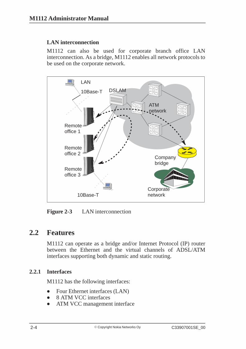
LAN interconnection
M1112 can also be used for corporate branch office LANinterconnection. As a bridge, M1112 enables all network protocols tobe used on the corporate network.
LAN
10Base-T
ATMnetwork
Companybridge
Remoteoffice 1
Remoteoffice 3
Corporatenetwork
DSLAM
Remoteoffice 2
10Base-T
Figure 2-3 LAN interconnection
2.2 FeaturesM1112 can operate as a bridge and/or Internet Protocol (IP) routerbetween the Ethernet and the virtual channels of ADSL/ATMinterfaces supporting both dynamic and static routing.
2.2.1 Interfaces
M1112 has the following interfaces:
� Four Ethernet interfaces (LAN)� 8 ATM VCC interfaces� ATM VCC management interface
Applications and features
� Copyright Nokia Networks OyC33907001SE_00 2-5
� Gateway/bridge management interface. This interface is used as abridge host interface or gateway interface depending on theoperation mode. In this manual it is called VBRIDGE. On theM1112 web pages, the interface is called gateway or bridge IPinterface.
M1112 can operate in four different main modes:
� Bridging only� Routing/tunneling IP only� Routing/tunneling IP, bridging all but IP� Routing/tunneling IP and bridging all, including IP
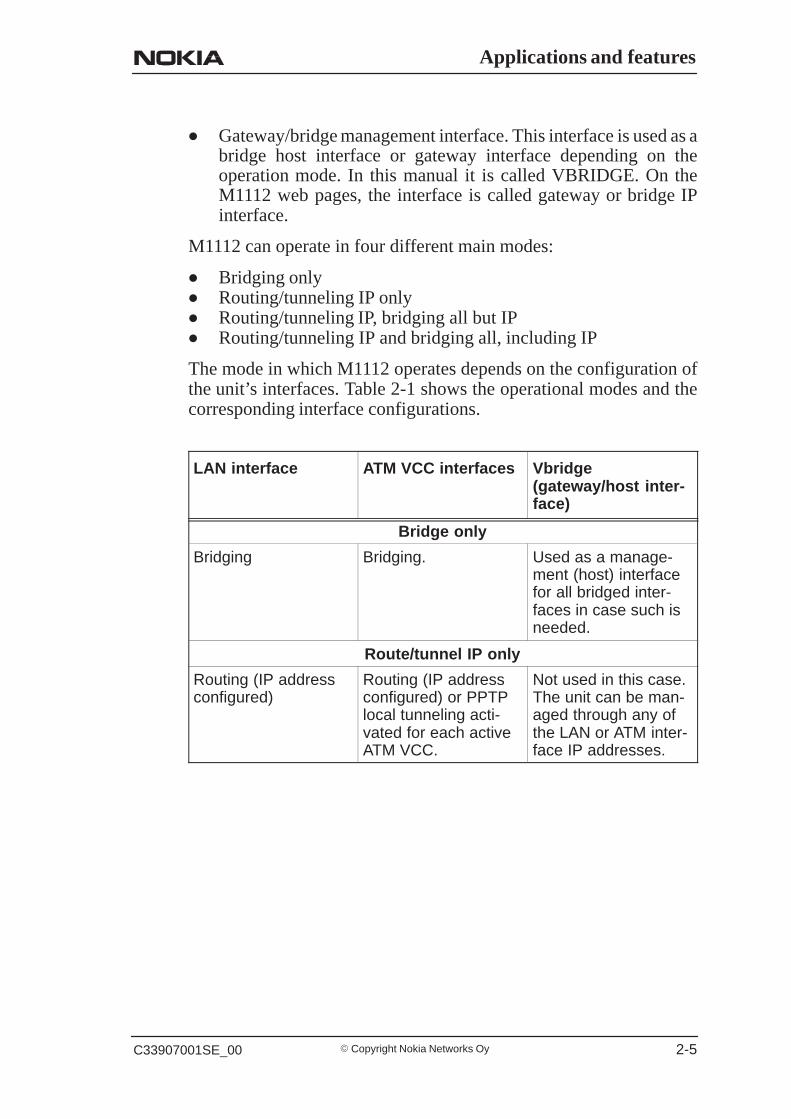
The mode in which M1112 operates depends on the configuration ofthe unit’s interfaces. Table 2-1 shows the operational modes and thecorresponding interface configurations.
LAN interface ATM VCC interfaces Vbridge(gateway/host inter-face)
Bridge only
Bridging Bridging. Used as a manage-ment (host) interfacefor all bridged inter-faces in case such isneeded.
Route/tunnel IP only
Routing (IP addressconfigured)
Routing (IP addressconfigured) or PPTPlocal tunneling acti-vated for each activeATM VCC.
Not used in this case.The unit can be man-aged through any ofthe LAN or ATM inter-face IP addresses.
M1112 Administrator Manual
� Copyright Nokia Networks Oy C33907001SE_00 2-6
LAN interface Vbridge(gateway/host inter-face)
ATM VCC interfaces
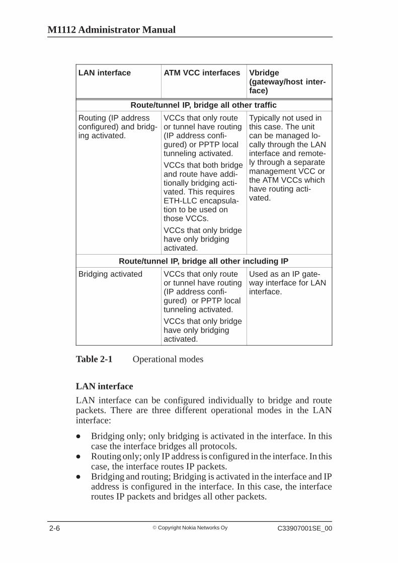
Route/tunnel IP, bridge all other traffic
Routing (IP addressconfigured) and bridg-ing activated.
VCCs that only routeor tunnel have routing(IP address confi-gured) or PPTP localtunneling activated.
VCCs that both bridgeand route have addi-tionally bridging acti-vated. This requiresETH-LLC encapsula-tion to be used onthose VCCs.
VCCs that only bridgehave only bridgingactivated.
Typically not used inthis case. The unitcan be managed lo-cally through the LANinterface and remote-ly through a separatemanagement VCC orthe ATM VCCs whichhave routing acti-vated.
Route/tunnel IP, bridge all other including IP
Bridging activated VCCs that only routeor tunnel have routing(IP address confi-gured) or PPTP localtunneling activated.
VCCs that only bridgehave only bridgingactivated.
Used as an IP gate-way interface for LANinterface.
Table 2-1 Operational modes
LAN interface
LAN interface can be configured individually to bridge and routepackets. There are three different operational modes in the LANinterface:
� Bridging only; only bridging is activated in the interface. In thiscase the interface bridges all protocols.
� Routing only; only IP address is configured in the interface. In thiscase, the interface routes IP packets.
� Bridging and routing; Bridging is activated in the interface and IPaddress is configured in the interface. In this case, the interfaceroutes IP packets and bridges all other packets.
Applications and features
� Copyright Nokia Networks OyC33907001SE_00 2-7
Internal host/gateway interface
There is a special host/gateway logical IP interface within M1112called VBRIDGE. This interface has a specific purpose in M1112. Inapplications where some ATM virtual channel connections are usedfor bridging IP traffic and some other ATM virtual channelconnections are used for routing IP traffic, the VBRIDGE interfacemust be used instead of LAN IP address. Alternatively, this interface isused in bridge only application when the IP address is required forremote management purposes.
Data VCC operation
M1112 supports the following encapsulations in each ATM datavirtual channel individually:
� RFC2684 LLC encapsulation for bridged IP (ETH-LLC)� RFC2684 LLC encapsulation for routed IP (IP-LLC)� RFC2364 Virtual circuit multiplexed PPP over AAL5 (PPP-VC)� RFC2364 Virtual circuit multiplexed PPP over AAL5 used to
tunnel LAN/VBRIDGE PPTP packets(TUNNELED-PPP-VC)
If an IP address is given to a virtual channel interface and bridging isenabled at that interface, then IP data at that interface is routed and allother protocols are bridged. The only encapsulation which allows bothbridging and routing simultaneously is ETH-LLC. For example, it ispossible to route ETH-LLC encapsulated packets and at the same timebridge, for example, PPPoE packets (PPPoE packets are transporteddirectly over Ethernet frame, not within IP packets).
2.2.2 Routing
Routing is based on routing entries in a routing table. Static routes areadded via the management interface and dynamic routing is done usingRIP and RIPv2. Routing is done between the Ethernet 10Base-Tinterface and the virtual channel connection (VCC) of the ATM/ADSLinterface. M1112 supports up to 8 simultaneous VCCs.
M1112 supports IGMP (Internet Group Management Protocol) proxyreceive function for IP multicast applications.
2.2.3 Bridging
Bridging is supported to provide full protocol transparency. Bridgingcan be used simultaneously with IP routing. M1112 works as a
M1112 Administrator Manual
� Copyright Nokia Networks Oy C33907001SE_00 2-8
self-learning bridge supporting up to 1024 MAC addresses. Bridgingis done between the Ethernet 10Base-T interface and each ATM VCCinterface. Optionally, the bridging between the VCCs can be disabled.
2.2.4 Network Address Port Translation
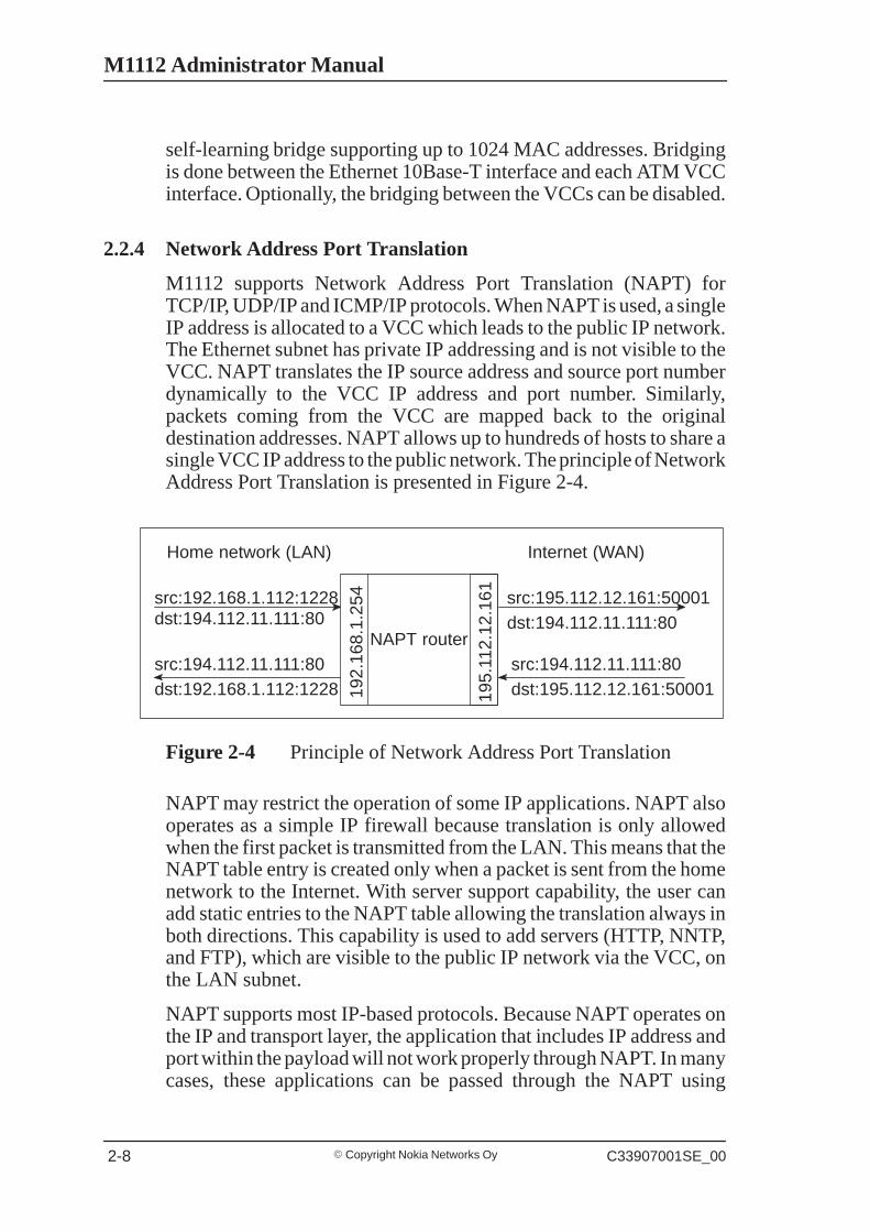
M1112 supports Network Address Port Translation (NAPT) forTCP/IP, UDP/IP and ICMP/IP protocols. When NAPT is used, a singleIP address is allocated to a VCC which leads to the public IP network.The Ethernet subnet has private IP addressing and is not visible to theVCC. NAPT translates the IP source address and source port numberdynamically to the VCC IP address and port number. Similarly,packets coming from the VCC are mapped back to the originaldestination addresses. NAPT allows up to hundreds of hosts to share asingle VCC IP address to the public network. The principle of NetworkAddress Port Translation is presented in Figure 2-4.
NAPT router
192.
168.
1.25
4
195.
112.
12.1
61src:192.168.1.112:1228dst:194.112.11.111:80
src:194.112.11.111:80dst:192.168.1.112:1228
src:195.112.12.161:50001dst:194.112.11.111:80
src:194.112.11.111:80dst:195.112.12.161:50001
Home network (LAN) Internet (WAN)
Figure 2-4 Principle of Network Address Port Translation
NAPT may restrict the operation of some IP applications. NAPT alsooperates as a simple IP firewall because translation is only allowedwhen the first packet is transmitted from the LAN. This means that theNAPT table entry is created only when a packet is sent from the homenetwork to the Internet. With server support capability, the user canadd static entries to the NAPT table allowing the translation always inboth directions. This capability is used to add servers (HTTP, NNTP,and FTP), which are visible to the public IP network via the VCC, onthe LAN subnet.
NAPT supports most IP-based protocols. Because NAPT operates onthe IP and transport layer, the application that includes IP address andport within the payload will not work properly through NAPT. In manycases, these applications can be passed through the NAPT using
Applications and features
� Copyright Nokia Networks OyC33907001SE_00 2-9
Application Layer Gateway functionality (ALG). M1112 has ALG forthe following protocols/applications:
� ICMP� FTP� H.323 including NetMeeting� CUSeeMe� PPTP� IRC� IPSEC ESP tunnel mode and IKE
Note, that most IPSEC implementations will fail when passed throughNAPT. A typical reason is that the identification may fail if theidentification is based on IP address. Also, only tunnel mode withoutAuthentication Header (AH) works.
2.2.5 Dynamic Host Configuration Protocol
M1112 can act as a Dynamic Host Configuration Protocol (DHCP)server for the PCs on the end-user home network. In this mode, M1112can assign up to 253+253 consecutive addresses from two separateaddress ranges (that is, 253 consecutive addresses per address range)to the PCs on the home network. Two separate address ranges can beused if more than 253 addresses are required on the local subnet, if twonon-contiguous ranges are needed or if an additional router withDHCP relay is used on the local network. M1112 can also act as aDHCP relay agent and relay the DHCP requests to an external DHCPserver.
2.2.6 ATM and ADSL
M1112 supports up to 8 simultaneous VCCs and supports UBR(Unspecified bit rate) traffic shaping on all VCCs. The maximumtransmit rate on each VCC is the ADSL upstream capacity. If morethan one VCC is transmitting simultaneously, the ADSL upstreamcapacity is temporarily shared between these VCCs. When one VCC isidle, the bandwidth is used by another VCC.
The ADSL transmission is based on the DMT line code. M1112provides a DMT line rate up to 8 Mbit/s downstream and up to 800kbit/s upstream. The DMT transceiver is rate adaptive and capable ofproviding faster rates over short distances or slower rates over longdistances. The transceiver adapts itself to the line conditions.
M1112 is compatible with ETSI 101 388.
M1112 Administrator Manual
� Copyright Nokia Networks Oy C33907001SE_00 2-10
Rate adaptation is done in steps of 32 kbit/s. The ADSL interface ofM1112 functions completely automatically and all configurationrelated to the ADSL connection is done at the access multiplexer in theoperator’s premises. The network operator can set the data rates as apart of the network management functionality provided by NokiaDSLAM.
2.2.7 Point-to-Point Tunneling Protocol (PPTP)
When PPTP local tunneling is used, a local network client initialises aPPTP-tunneled PPP connection (VPN) to Nokia M1112. The modemterminates the tunnel and all data from that terminated local PPTPtunnel will be forwarded to an assigned ATM VCC by using PPP overAAL5 encapsulation. Thus, each local PPTP tunnel requires anequivalent ATM VCC assigned to it restricting the total number oflocal PPTP hosts to 8.
Local tunneling is used when there is a need to have one or morecomputers connected independently to different networks. Forexample, in remote work application, the rest of the family may beusing the common ISP services and one or two family members need togain access to their corporate networks. With local tunneling, theseremote workers may be connected to a different network than the restof the users.
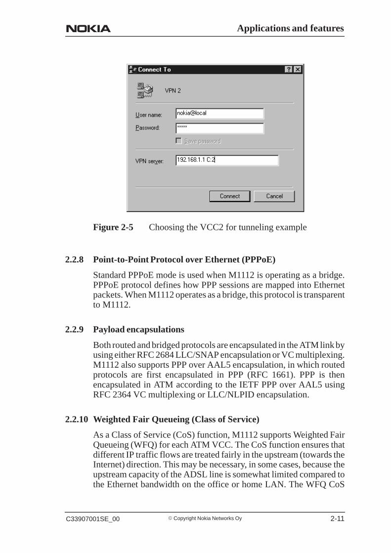
Local tunneling is activated using the PPTP client running, forexample, in Windows The destination IP address must be M1112LAN/VBRIDGE IP address depending on the configuration. PPPpackets within PPTP are mapped to the configured VCC. M1112 hasthree different ways to choose the ATM VCC that will be used fortunneling:
� Automatic, chooses the first free VCC� Chooses the VCC number using C:number, where number is from
1 to 8. C:number is typed after the M1112 IP address in PC’s PPTPclient Connect To window (see Figure 2-5).
� Chooses the VCC number using N:name, where name is theVCCx description. N:name is fed after the M1112 IP address.
Applications and features
� Copyright Nokia Networks OyC33907001SE_00 2-11
Figure 2-5 Choosing the VCC2 for tunneling example
2.2.8 Point-to-Point Protocol over Ethernet (PPPoE)
Standard PPPoE mode is used when M1112 is operating as a bridge.PPPoE protocol defines how PPP sessions are mapped into Ethernetpackets. When M1112 operates as a bridge, this protocol is transparentto M1112.
2.2.9 Payload encapsulations
Both routed and bridged protocols are encapsulated in the ATM link byusing either RFC 2684 LLC/SNAP encapsulation or VC multiplexing.M1112 also supports PPP over AAL5 encapsulation, in which routedprotocols are first encapsulated in PPP (RFC 1661). PPP is thenencapsulated in ATM according to the IETF PPP over AAL5 usingRFC 2364 VC multiplexing or LLC/NLPID encapsulation.
2.2.10 Weighted Fair Queueing (Class of Service)
As a Class of Service (CoS) function, M1112 supports Weighted FairQueueing (WFQ) for each ATM VCC. The CoS function ensures thatdifferent IP traffic flows are treated fairly in the upstream (towards theInternet) direction. This may be necessary, in some cases, because theupstream capacity of the ADSL line is somewhat limited compared tothe Ethernet bandwidth on the office or home LAN. The WFQ CoS
M1112 Administrator Manual
� Copyright Nokia Networks Oy C33907001SE_00 2-12
function classifies IP traffic flows based on IP address, protocol andport fields. It is capable of identifying the IP flow from all supportedpayload encapsulation formats. WFQ works properly only withIP-based protocols. If the flow is IP-based but is encrypted using IPSecor PPP encryption, then WFQ cannot identify the flows correctly. Inthis case, the default flow is used and the default flow is treated as asingle flow.
2.2.11 Management
There are three management methods in M1112:
� Command line interface (CLI) through console serial port� CLI via telnet� Web browser management
The CLI allows complete configuration of the unit; the Web browsermanagement allows the configuration of the most frequently usedconfiguration parameters.
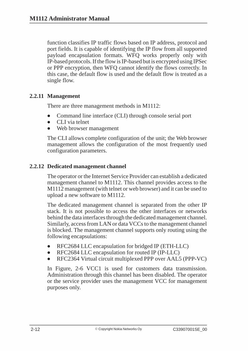
2.2.12 Dedicated management channel
The operator or the Internet Service Provider can establish a dedicatedmanagement channel to M1112. This channel provides access to theM1112 management (with telnet or web browser) and it can be used toupload a new software to M1112.
The dedicated management channel is separated from the other IPstack. It is not possible to access the other interfaces or networksbehind the data interfaces through the dedicated management channel.Similarly, access from LAN or data VCCs to the management channelis blocked. The management channel supports only routing using thefollowing encapsulations:
� RFC2684 LLC encapsulation for bridged IP (ETH-LLC)� RFC2684 LLC encapsulation for routed IP (IP-LLC)� RFC2364 Virtual circuit multiplexed PPP over AAL5 (PPP-VC)
In Figure, 2-6 VCC1 is used for customers data transmission.Administration through this channel has been disabled. The operatoror the service provider uses the management VCC for managementpurposes only.
Applications and features
� Copyright Nokia Networks OyC33907001SE_00 2-13
Internet
LAN
10Base-T
Homenetwork
VCC1/Data(admin disabled)
ISP’s NMS Net-work manage-ment system
Management VCC
Nokia M1112
Figure 2-6 Dedicated management channel

M1112 Administrator Manual
� Copyright Nokia Networks Oy C33907001SE_00 2-14
Interfaces and indicator lights
� Copyright Nokia Networks OyC33907001SE_00 3-1
Chapter 3Interfaces and indicator lights
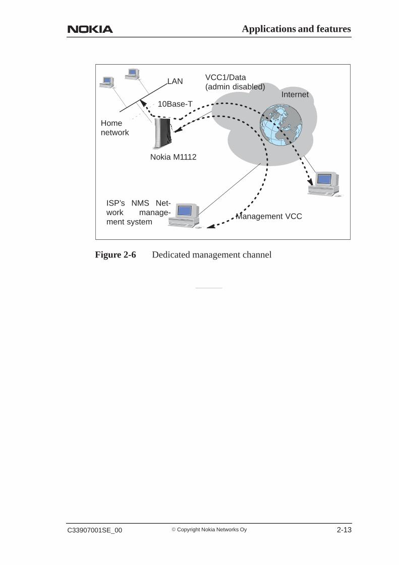
This chapter describes the external interfaces of M1112 and introducesits front panel indicator lights.
3.1 InterfacesM1112 has one ADSL line interface and one LAN interface (10Base-TEthernet). It also has a local management interface (CLI) formanagement purposes. The ADSL line interface is compatible withETSI TS 101 388 specification.
ADSL line (DSL)Ethernet ports(ETH-1, ETH-2,ETH-3, ETH-4)Command line interface (CLI)
Mains connector
Power switch
Figure 3-1 M1112 back panel

M1112 Administrator Manual
� Copyright Nokia Networks Oy C33907001SE_00 3-2
3.1.1 Ethernet interface
The Ethernet interface (ETH) is located on the back panel. TheEthernet interface is a standard 10 Mbit/s half-duplex 10Base-Tinterface. The mechanical connector is an 8-pin RJ-45. The pin-outnumbering is shown in Table 3-1.
1 8
Figure 3-2 ETH connector
PIN Signal Direction
M1112-Ethernet
MDI signal
1 Rx+ <– Receive data +2 Rx– <– Receive data –3 Tx+ –> Transmit data +6 Tx– –> Transmit data –
Table 3-1 Ethernet interface pin-out numbering
3.1.2 ADSL interface
The ADSL interface (DSL) is compatible with ETSI TS 101 388specification. The mechanical connector is a 6-pin RJ-11. The pin-outnumbering is shown in Table 3-2.
1 6
Figure 3-3 DSL connector
Interfaces and indicator lights
� Copyright Nokia Networks OyC33907001SE_00 3-3
PIN Signal
3 DSL14 DSL2
Table 3-2 ADSL interface pin-out numbering
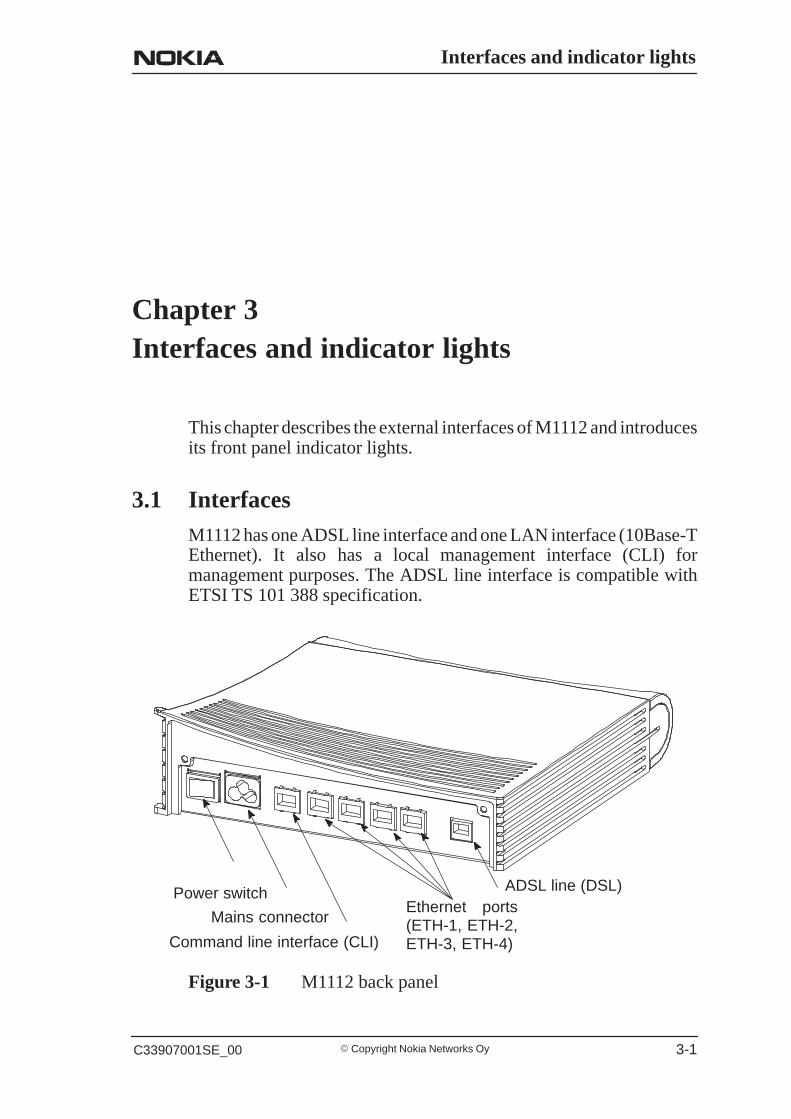
3.2 Command line interfaceThe command line interface (CLI) is RS-232 interface with an RJ-45mechanical connector. The pin-out numbering is shown in Table 3-3.
1 8
Figure 3-4 CLI connector
PIN Signal DirectionM5112-ter-
minal
MDI signal
1 107 DSR(const. ON)
–> Data set ready
2 108 DTR <– Data terminal ready3 109 DCD
(const. ON)–> Data channel re-
ceived line signal de-tector
4 102 SG Signal ground5 103 TxD <– Transmitted data6 104 RxD –> Received data7 105 RTS
(not in use)<– Request to send
8 106 CTS(const. ON)
–> Clear to send
Table 3-3 Command line interface pin-out numbering

M1112 Administrator Manual
� Copyright Nokia Networks Oy C33907001SE_00 3-4
3.3 Indicator lightsM1112 has eight indicator lights on the front panel: PWR, STA, COL,ETH-1, ETH-2, ETH-3, ETH-4, and DSL. STA indicator is red. Otherindicators are green.
Figure 3-5 M1112 front panel indicators
DSL GREEN
Off ADSL link is down.Blinks ADSL connection is being established.On ADSL link is up.
ETH- GREEN
Off Ethernet is down.On 10Base-T Ethernet is functionalBlinks Receives traffic from Ethernet.
COL GREEN
Blinks Collisions on the Ethernet. Note, that it is normal that somecollisions occur on the Ethernet.

Interfaces and indicator lights
� Copyright Nokia Networks OyC33907001SE_00 3-5
STA RED
Off OKOn Hardware malfunction during startup.
PWR GREEN
Off Power off.On Power on.

M1112 Administrator Manual
� Copyright Nokia Networks Oy C33907001SE_00 3-6
Installing Nokia M1112
� Copyright Nokia Networks OyC33907001SE_00 4-1
Chapter 4Installing Nokia M1112
This chapter presents a step-by-step installation procedure of M1112.Before starting the installation check that M1112 is physicallyundamaged. The package contains the following items:
� M1112 modem� ADSL line cable� Straight 10Base-T Ethernet cable� power cord� serial adapter� User Manual
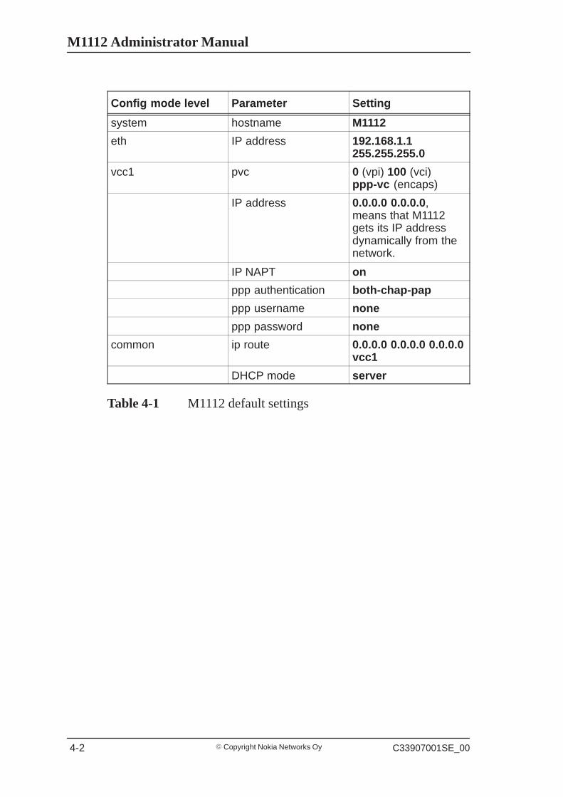
4.1 M1112 default settingsTypically, M1112 has a customer-specific configuration. The defaultconfiguration of a general version is shown in Table 4-1.
M1112 Administrator Manual
� Copyright Nokia Networks Oy C33907001SE_00 4-2
Config mode level Parameter Setting
system hostname M1112
eth IP address 192.168.1.1255.255.255.0
vcc1 pvc 0 (vpi) 100 (vci)ppp-vc (encaps)
IP address 0.0.0.0 0.0.0.0,means that M1112gets its IP addressdynamically from thenetwork.
IP NAPT on
ppp authentication both-chap-pap
ppp username none
ppp password none
common ip route 0.0.0.0 0.0.0.0 0.0.0.0vcc1
DHCP mode server
Table 4-1 M1112 default settings

Installing Nokia M1112
� Copyright Nokia Networks OyC33907001SE_00 4-3
4.2 Step-by-step installation procedure1. Plug the mains power cord to a mains outlet.2. Switch on M1112. The PWR indicator lights up.3. Connect the 8-pin Ethernet cable between your PC’s 10 Base-T
Ethernet card and the Ethernet connector on the M1112 backpanel.
4. Switch on your PC. The indicator corresponding the Ethernet portyou connected your PC to becomes green when your PC hasstarted. This indicator blinks when there is traffic in thecorresponding Ethernet port.
5. Connect the 6-pin ADSL line cable between the ADSL connectoron the M1112 back panel and your ADSL line wall socket. If youwant to use ISDN and ADSL data services simultaneously,connect a splitter according to Figure 4-1. After a while, the DSLindicator starts blinking indicating that the ADSL connection isbeing established. After the connection has been establishedsuccessfully the DSL indicator remains lit.
6. During normal operation PWR and DSL indicators are lit and theEthernet indicators of the active Ethernet ports blink or are litdepending whether there is traffic or not. COL indicator may blinkoccasionally during normal operation.
splitter
ISDN NT1
U int.
S int.
Figure 4-1 M1112 and splitter connected
Now, your M1112 has been connected and you can check theconnections according to your service provider’s instructions. See

M1112 Administrator Manual
� Copyright Nokia Networks Oy C33907001SE_00 4-4
Chapter 5 Managing M1112 for instructions on how to configureM1112.
Managing M1112
� Copyright Nokia Networks OyC33907001SE_00 5-1
Chapter 5Managing M1112
This chapter shows some operational examples of M1112. Theexamples can be used as a guide when you are planning yourconfiguration. After the operational examples, we introduce themanagement methods of M1112. First we show how to use the webbrowser management and then the command line interface (CLI) willbe presented. The command line interface section contains all CLIcommands.
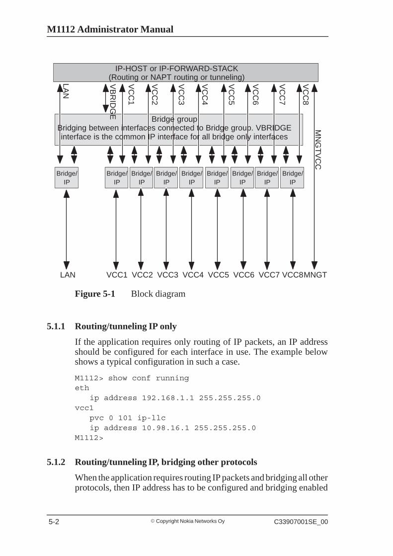
5.1 Operational examplesThis section presents some typical operational examples and thecorresponding configurations. Figure 5-1 shows a general blockdiagram of the IP forwarding and bridging functions of M1112.
M1112 Administrator Manual
� Copyright Nokia Networks Oy C33907001SE_00 5-2
IP-HOST or IP-FORWARD-STACK(Routing or NAPT routing or tunneling)
Bridge/IP
Bridge/IP
Bridge/IP
Bridge/IP
Bridge/IP
Bridge/IP
Bridge/IP
Bridge/IP
Bridge/IP
Bridge groupBridging between interfaces connected to Bridge group. VBRIDGEinterface is the common IP interface for all bridge only interfaces
LAN
VB
RID
GE
VC
C1
VC
C8
VC
C7
VC
C6
VC
C5
VC
C4
VC
C3
VC
C2
MN
GT
VC
C
LAN VCC1 VCC8VCC7VCC6VCC5VCC4VCC3VCC2 MNGT
Figure 5-1 Block diagram
5.1.1 Routing/tunneling IP only
If the application requires only routing of IP packets, an IP addressshould be configured for each interface in use. The example belowshows a typical configuration in such a case.
M1112> show conf runningeth
ip address 192.168.1.1 255.255.255.0vcc1
pvc 0 101 ip-llcip address 10.98.16.1 255.255.255.0
M1112>
5.1.2 Routing/tunneling IP, bridging other protocols
When the application requires routing IP packets and bridging all otherprotocols, then IP address has to be configured and bridging enabled
Managing M1112
� Copyright Nokia Networks OyC33907001SE_00 5-3
for all relevant interfaces. The result is that IP packets will be routedand all other packets will be bridged. In the configuration examplebelow, LAN interface routes IP traffic and bridges all other protocols.ATM VCC1 routes IP traffic and ATM VCC2 interfaces bridges alltraffic.
M1112> show config runningeth
ip address 192.168.1.1 255.255.255.0bridging
vcc1pvc 0 101 ip-llcip address 10.98.16.1 255.255.255.0
vcc2pvc 0 102 eth-llc
bridgingM1112>
5.1.3 Routing/tunneling IP, bridging all protocols including IP
When IP packets that are received from LAN must be routed/tunneledto some ATM VCC and bridged to some other ATM VCC, then theVBRIDGE interface must be used as this common IP interface for allbridged interfaces. LAN interface is in this case configures as bridgeonly.
M1112> show config runningeth
bridgingvcc1
pvc 0 101 ip-llcip address 10.98.16.1 255.255.255.0
vcc2pvc 0 102 tunneled-ppp-vc
vcc3pvc 0 103 eth-llcbridging
vbridgeip address 192.168.1.1 255.255.255.0
M1112>

M1112 Administrator Manual
� Copyright Nokia Networks Oy C33907001SE_00 5-4
5.1.4 Bridging only
When only bridging is required, all ATM VCCs are configured asbridge. VBRIDGE IP address can be used as an optional managementinterface.
M1112> show config runningeth
bridgingvcc1
pvc 0 101 eth-llcbridging
vcc2pvc 0 102 eth-llcbridging
vbridgeip address 192.168.1.1 255.255.255.0
M1112>
5.2 Typical configuration tasksThis section provides some typical configuration tasks. Theseconfiguration examples can be done through the command lineinterface.
NoteAfter you have made changes to the configuration, you must save theconfiguration if you want it to be active also after restarting M1112.
5.2.1 Configuring DHCP and DNS
The DHCP server can be enabled towards LAN and VBRIDGE ports.When the DHCP server is enabled, up to two address ranges (scopes)will be automatically generated and bound to LAN/VBRIDGEinterfaces, in this order, if the interface has an IP address. Two separateaddress ranges can be used if more than 253 addresses are required onthe local subnet, if two non-contiguous adress ranges are needed or ifan additional router with DHCP relay is used on the local network.
The address range defines pool of IP addresses and parameters likedefault gateway, DNS addresses and domain name. The generateddefault address range allows up to 253 IP addresses (C class).
Managing M1112
� Copyright Nokia Networks OyC33907001SE_00 5-5
Automatically generated address ranges use LAN/VBRIDGE IPaddress as gateway and DNS server addresses. If one address range isdefined, then automatic binding will be disabled. If optional addressrange parameters like gateway or DNS addresses are not defined,LAN/VBRIDGE IP addresses are used as in automatic binding.
Typically, when DHCP is used, the advertised DSN addresses point toLAN/VBRIDGE interfaces. In such cases, the DNS proxy forwardsthe DNS request to statically configured DNS servers or to DNSservers learned dynamically vie PPP/IPCP.
The following commands are used to configure DHCP and DNSsettings:
M1112(conf-common)#dhcp?usage: dhcp mode
dhcp addressdhcp gatewaydhcp dnsdhcp lease-timedhcp domain-name
M1112(conf-common)#dhcp mode server ; this enablesDHCP server
Normally, there is no need to configure the DNS addresses. If theservice provider does not support automatic DNS address allocation,the DNS servers can be configured as shown by the followingexample:
M1112(conf-common)# dns address primary 1.2.3.4M1112(conf-common)# dns address secondary 1.2.3.5M1112(conf-common)#
5.2.2 Configuring static and dynamic routing
Routing entries in the routing table are needed in order to forward theIP packets to the correct interface. M1112 has both static and dynamicroutes. Static routes are configured manually and dynamic routes arelearned automatically using RIP v1 and RIP v2 protocols. Thefollowing examples show how to configure static routes to M1112.
Default gateway for an interface that learns the next hop automatically:M1112(conf-common)# ip route 0.0.0.0 0.0.0.0 0.0.0.0vcc1

M1112 Administrator Manual
� Copyright Nokia Networks Oy C33907001SE_00 5-6
Default gateway for an interface that requires static next hop:M1112(conf-common)# ip route 0.0.0.0 0.0.0.0 1.2.3.1vcc1
Static route for an interface that learns the next hop automatically:M1112(conf-common)# ip route 131.132.133.0255.255.255.0 0.0.0.0 vcc1
Static route for an interface that requires a static next hop:M1112(conf-common)# ip route 131.132.133.0255.255.255.0 1.3.5.1 vcc1
M1112 can have only one default gateway. The interfaces that canlearn gateway/peer address dynamically can use value 0.0.0.0 insteadof the next hop address.
5.2.3 File system and downloading new firmware using TFTP
M1112 has a flash file system. Some files in the file system havespecial meanings. These files are:
� image.exe; primary application file.� image.bak; secondary application file used if image.exe has been
corrupted or is missing. It is then renamed as image.exeautomatically.
� startup.cfg; primary configuration file used during startup.� dhcp.leases; contains DHCP lease table information.
M1112 has the following commands that can be used for file handling:
� copy� rename� delete� dir
If you use image.exe as a destination filename with the copy commandand the image.exe already exists, the existing image.exe will beautomatically renamed as image.bak. This guarantees that theapplication file exists if M1112 loses power during SW download.
You can update the operating software of M1112 by downloading thenew software from a TFTP server. To download and activate newM1112 operating software:
Managing M1112
� Copyright Nokia Networks OyC33907001SE_00 5-7
1. Use CLI to issueinstall tftp:/<ip-address>/Gx1x2200.R00 command,where <ip-address is the IP address of the TFTP servercontaining the new software and Gx1x2200.R00 is the name of thefile to be downloaded. The command copytftp:/<ip-address>/Gx1x2200.R00 image.exe can be usedalternatively.
2. After you will see transfer status SUCCESSFULmessage, restart M1112 to activate the new software.
Downloading configuration or application from monitor
Monitor is a small application that is executed before the actualsoftware image is started. Typically the Monitor automatically loadsthe application file image.exe. You can activate the Monitor bypressing “m” followed by “o” in the very beginning of the systemstartup:
local MAC=00:40:43:02:36:72; Using M111/850 eth confType ’m’ (fast) followed by ’o’ (in 10 sec) toactivate MonitorNokia Networks (C) 1999Nokia BootB-R0.0.0. built on Apr 4 2000 11:27:55MON>
The following commands are available for file handling in theMonitor:
� rename� delete� dir
M1112 has two methods of retrieving files:
� TFTP� XMODEM
You can retrieve files from a TFTP server using the commands in thefollowing example:
MON>ipa 192.168.1.1ip=192.168.1.1
ipserver=0.0.0.0ipgw=0.0.0.0
serverfile=MON>ips 192.168.1.100

M1112 Administrator Manual
� Copyright Nokia Networks Oy C33907001SE_00 5-8
ip=192.168.1.1ipserver=192.168.1.100
ipgw=0.0.0.0serverfile=MON>file startup.cfg
ip=192.168.1.1ipserver=192.168.1.100
ipgw=0.0.0.0serverfile=startup.cfgMON>egettftp loader
ip=192.168.1.1ipserver=192.168.1.100
ipgw=0.0.0.0serverfile=startup.cfgloading file...file size=556MON>wri startup.cfgWriting successfulMON>
A file can also be transmitted from an XMODEM1K running in a PC,for example, as in the following example:
MON>xgetStart Xmodem1k sending...MON>wri image.exeWriting successfulMON>
5.3 Browser managementM1112 can be managed with a web browser or command line interface(CLI). The web configuration pages of M1112 can be accessedthrough the Ethernet or through the ADSL/ATM channels of M1112.In order to access the web management feature, the IP functionalitymust be activated and an IP address must be given to the correspondinginterface.
You can use your PC’s web browser software to access the webconfiguration pages in M1112. To access the web pages you mustknow the IP address of your M1112 or, alternatively, the “name” thatyour M1112 recognises.

Managing M1112
� Copyright Nokia Networks OyC33907001SE_00 5-9
NoteBefore using your web browser for configuration, you must know theIP address or the name assigned to your M1112.
There are three ways to find out whether to use a name or an IPaddress:
� Your service provider has given you an IP address for M1112.� Your M1112 uses Dynamic Host Configuration Protocol (DHCP)
and Domain Name Server. In this case the name is M1112.� Your M1112 uses DHCP. In this case run winipcfg.exe (Windows
95) or ipconfig.exe (Windows NT). The IP address of M1112 is theDefault Gateway address shown by the ipconfig program.
5.3.1 Opening a connection
To open a connection to the Nokia M1112:
1. Start your web browser.2. Enter the name (’M1112’) or IP address of your Nokia M1112 in
the browser’s Open Location field and press Enter. If you use theIP address, it has to be assigned to a local port or gateway interface(VBRIDGE).
3. Type in the username/password as requested. If nousername/password is required, just click OK to proceed. TheNokia M1112 Main Page appears.
M1112 Administrator Manual
� Copyright Nokia Networks Oy C33907001SE_00 5-10
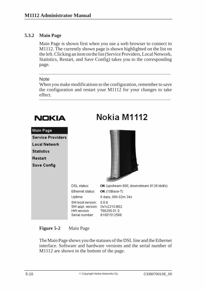
5.3.2 Main Page
Main Page is shown first when you use a web browser to connect toM1112. The currently shown page is shown highlighted on the list onthe left. Clicking an item on the list (Service Providers, Local Network,Statistics, Restart, and Save Config) takes you to the correspondingpage.
NoteWhen you make modifications to the configuration, remember to savethe configuration and restart your M1112 for your changes to takeeffect.
Figure 5-2 Main Page
The Main Page shows you the statuses of the DSL line and the Ethernetinterface. Software and hardware versions and the serial number ofM1112 are shown in the bottom of the page.
Managing M1112
� Copyright Nokia Networks OyC33907001SE_00 5-11
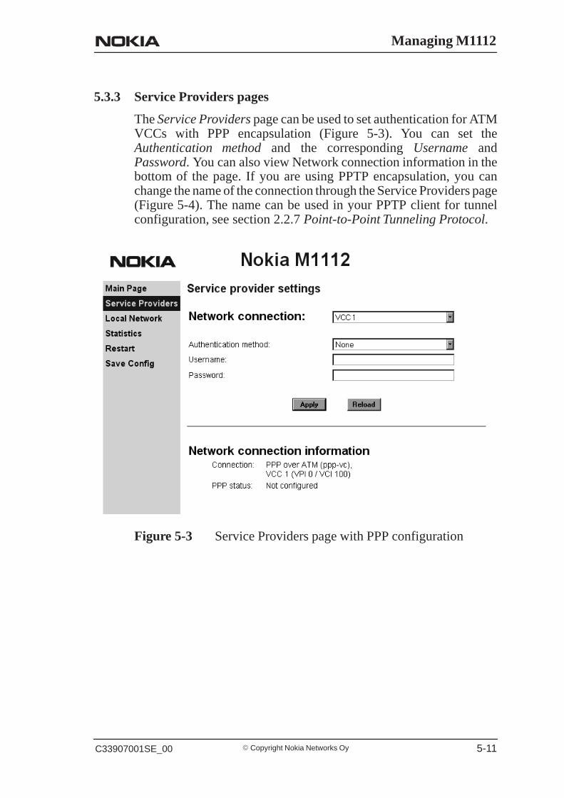
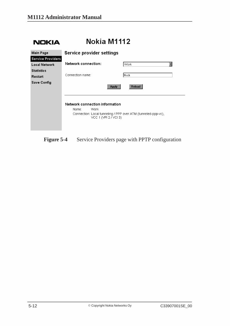
5.3.3 Service Providers pages
The Service Providers page can be used to set authentication for ATMVCCs with PPP encapsulation (Figure 5-3). You can set theAuthentication method and the corresponding Username andPassword. You can also view Network connection information in thebottom of the page. If you are using PPTP encapsulation, you canchange the name of the connection through the Service Providers page(Figure 5-4). The name can be used in your PPTP client for tunnelconfiguration, see section 2.2.7 Point-to-Point Tunneling Protocol.
Figure 5-3 Service Providers page with PPP configuration
M1112 Administrator Manual
� Copyright Nokia Networks Oy C33907001SE_00 5-12
Figure 5-4 Service Providers page with PPTP configuration

Managing M1112
� Copyright Nokia Networks OyC33907001SE_00 5-13
5.3.4 Local Network pages
The Local Network page as four sub pages: Local ports, DHCP, NAPT,and Routing.
Local ports
On the Local Network Local Ports sub page you can assign an IPaddress to the Ethernet port.
NoteWhen you click Apply, the IP addresses are changed immediately. Ifthe IP address of the interface you are using changes the connectionwill be lost. You have to reconfigure the IP address of the accessinghost. For example, in Windows programs winipcfg.exe oripconfig.exe must be used first to release the old address and then torenew to request new address.
Figure 5-5 Local Network Local Ports page
DHCP
On the Local Network DHCP subpage you can enable/disableDynamic Host Control Protocol and set the Address ranges fromwhich the addresses are distributed to the DHCP clients on yournetwork. You can also set the Domain Name Server addresses here.
M1112 Administrator Manual
� Copyright Nokia Networks Oy C33907001SE_00 5-14
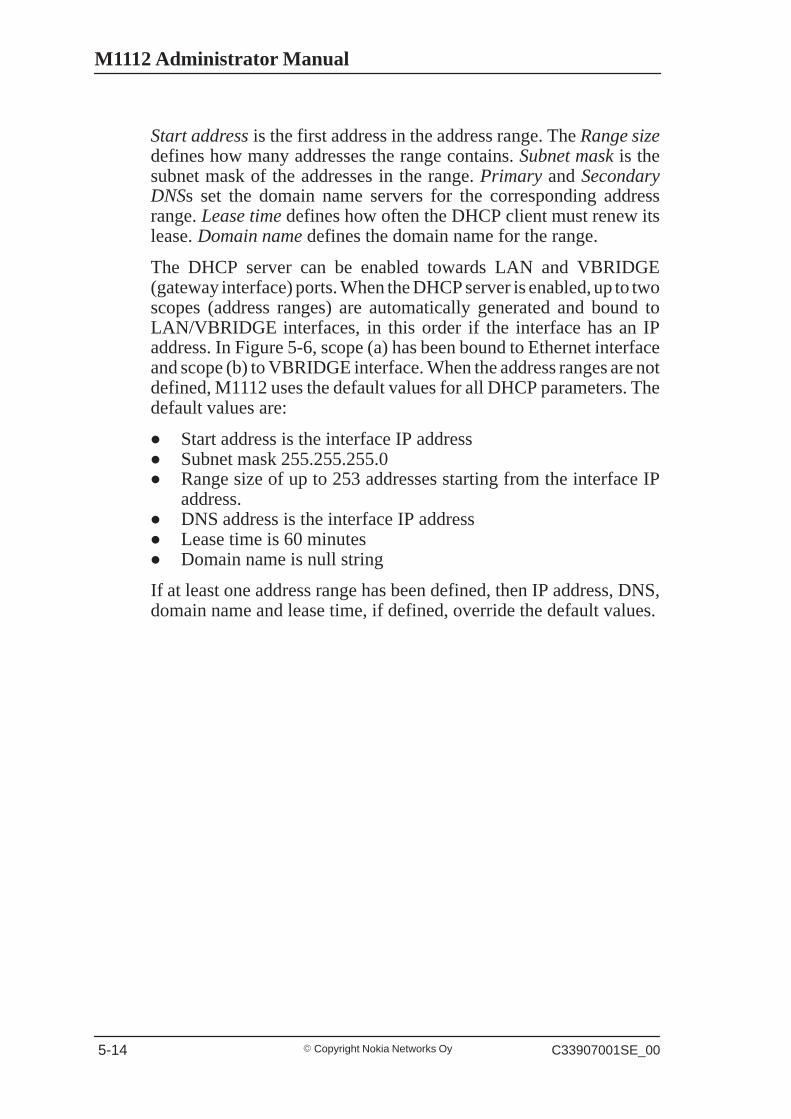
Start address is the first address in the address range. The Range sizedefines how many addresses the range contains. Subnet mask is thesubnet mask of the addresses in the range. Primary and SecondaryDNSs set the domain name servers for the corresponding addressrange. Lease time defines how often the DHCP client must renew itslease. Domain name defines the domain name for the range.
The DHCP server can be enabled towards LAN and VBRIDGE(gateway interface) ports. When the DHCP server is enabled, up to twoscopes (address ranges) are automatically generated and bound toLAN/VBRIDGE interfaces, in this order if the interface has an IPaddress. In Figure 5-6, scope (a) has been bound to Ethernet interfaceand scope (b) to VBRIDGE interface. When the address ranges are notdefined, M1112 uses the default values for all DHCP parameters. Thedefault values are:
� Start address is the interface IP address� Subnet mask 255.255.255.0� Range size of up to 253 addresses starting from the interface IP
address.� DNS address is the interface IP address� Lease time is 60 minutes� Domain name is null string
If at least one address range has been defined, then IP address, DNS,domain name and lease time, if defined, override the default values.
Managing M1112
� Copyright Nokia Networks OyC33907001SE_00 5-15
Figure 5-6 Local Network DHCP page

M1112 Administrator Manual
� Copyright Nokia Networks Oy C33907001SE_00 5-16
NAPT
If Network Address Port Translation (NAPT) has been activated,servers on your local network are not visible outside your network. OnNAPT page, you can configure pinholes through which you canprovide outside access to your web server from the Internet, forexample.
In the example shown in Figure 5-7, a pinhole has been added on theServer list. This example means that all TCP traffic coming from theInternet through VCC1 to ports 80...89 will be mapped to the IPaddress 192.168.1.15 ports 90...99 on your local network.
Figure 5-7 Local Network NAPT page

Managing M1112
� Copyright Nokia Networks OyC33907001SE_00 5-17
Routing page
On the Local Network Routing sub page you can set static routes andenable/disable dynamic routing protocols (Routing InformationProtocol version 1 and 2).
To enable dynamic routing to a particular interface select the Routingprotocol version from the pull-down list and click the Apply button.RIP versions 1 and 2 are supported. Send v1-compat. v2 option enablesthe sending of RIPv2 packets using broadcast. Receive v1-compat. v2option enables the receiving of both RIPv1 and RIPv2 packets.
To add a static route, type in the Destination network IP address, theSubnet mask of the destination network, and the Gateway and theInterface through which the destination network can be reached. Thenclick the Add new button. There are two static routes in Figure 5-8.
Figure 5-8 Local Network Routing page

M1112 Administrator Manual
� Copyright Nokia Networks Oy C33907001SE_00 5-18
5.3.5 Statistics page
The Statistics page lets you view a selection of M1112 statistics. toview statistics of a particular function, click the corresponding buttonand the statistics view is opened on a separate window.
Figure 5-9 Statistics page
Managing M1112
� Copyright Nokia Networks OyC33907001SE_00 5-19
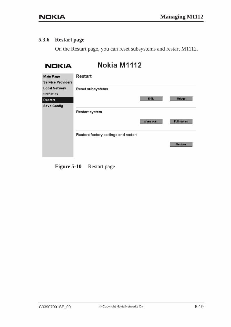
5.3.6 Restart page
On the Restart page, you can reset subsystems and restart M1112.
Figure 5-10 Restart page

M1112 Administrator Manual
� Copyright Nokia Networks Oy C33907001SE_00 5-20
5.3.7 Save Config page
When you change the configuration, all configuration changes areactivated immediately without restart/reload. However, theconfiguration will not be saved into the nonvolatile memory. If M1112is restarted or powered down without saving the configuration, the oldconfiguration will be restored. Clicking the Save configuration buttonsaves the configuration into the nonvolatile memory and the oldconfiguration cannot be restored through the web interface.
Figure 5-11 Save Config page
5.4 Command line interface (CLI)M1112 can be managed locally through a command line interface(CLI). The local command line interface is accessed through the localmanagement console on the back panel. The local managementconsole interface is an asynchronous V.24/V.28 character-basedinterface with the following configuration:

Managing M1112
� Copyright Nokia Networks OyC33907001SE_00 5-21
Setting Value
Speed 9600
Parity None
Data bits 8
Stop bits 1
Duplex Full
Flow control None
Table 5-1 Local management console configuration
Use the 10Base-T Ethernet cable with the serial adapter to connect youPC’s serial port to the local management console interface according toFigure 5-12.
serial adapter
10Base-TEthernet cable
Figure 5-12 Local management cabling
The command line interface can also be accessed through the Ethernetport of M1112 or through the ATM channels of M1112 on top of thetelnet protocol. In order to use the CLI through telnet or the ATMchannel, the IP function must be switched on and IP address must begiven to the corresponding interface.
M1112 can also be managed remotely through a separate ATM virtualchannel. This channel is only used for management purposes. In orderto use this management channel, it has to be activated first and given anIP address configuration. The management traffic to this interface isnot routed to any other interfaces of M1112.
M1112 Administrator Manual
� Copyright Nokia Networks Oy C33907001SE_00 5-22
The command line interface has been divided into two modes: mainand configuration. The main mode lets you monitor the status andperformance of M1112. The configuration mode lets you changeM1112 configuration. The CLI is case sensitive. All commands mustbe given in lower case characters. Only file names and strings cancontain upper case characters.
In the configuration mode, functions can be activated by typing thecorresponding command, for example bridging. The function can bedeactivated by simply typing no bridging. In commands whichrequire typing in parameter values, the default value can be restored bytyping de ppp mru, for example. de in front of the command means“default”. If you type in a value which is incorrect (for example, lettersinstead of numbers), the CLI prompts you to enter the value correctlyand displays help. You can always get help on the command or displayby typing help or ? at the command prompt.
You can recall you previous commands by pressing the “up-arrow”key on your keyboard.
The configuration mode has been divided into levels. You can navigatethrough the configuration mode by typing the name of the level. Bytyping exit you will return to the main mode. top command returnsyou to the root level of the configuration mode (M1112(conf)#).
The configuration mode levels are:
� system� password� eth� vcc1, vcc2, vcc3, vcc4, vcc5, vcc6, vcc7, and vcc8� vbridge� mngtvcc� common.
The example below shows how to access the different levels:
M1112>M1112>confM1112(conf)#systemM1112(conf-system)#passwordM1112(conf-password)#ethM1112(conf-eth)#vcc1M1112(conf-vcc1)#vcc2M1112(conf-vcc2)#vcc3M1112(conf-vcc3)#vcc4
Managing M1112
� Copyright Nokia Networks OyC33907001SE_00 5-23
M1112(conf-vcc4)#vcc5M1112(conf-vcc5)#vcc6M1112(conf-vcc6)#vcc7M1112(conf-vcc7)#vcc8M1112(conf-vcc8)#vbridgeM1112(conf-vbridge)#mngtvccM1112(conf-mngtvcc)#commonM1112(conf-common)#topM1112(conf)#exitM1112>
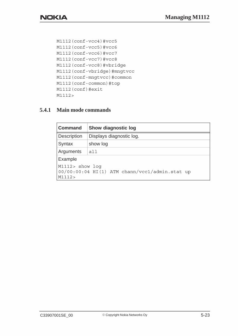
5.4.1 Main mode commands
Command Show diagnostic log
Description Displays diagnostic log.
Syntax show log
Arguments all
Example
M1112> show log00/00:00:04 HI(1) ATM chann/vcc1/admin.stat upM1112>

M1112 Administrator Manual
� Copyright Nokia Networks Oy C33907001SE_00 5-24
Command Show DSL line status
Description Displays DSL line status
Syntax show dsl [all]
Arguments all
Example
M1112> show dsl
hardware-type ALCATEL/DMThardware-rev 99111601/ISDN/CPfirmware-rev 00002508activity-statusOPER/FULL
near-end far-endmaximum-bitrate5696kbits 448kbitsactual-bitrate4608kbits 416kbitsnoise-margin 3.5dB 0.0dBoutput-power 12.0dBm 20dBmattenuation 48.5dB 0.0dBcorr-fast-fec 0 0corr-intl-fec 47 0fail-fast-crc 0 0fail-intl-crc 0 0fail-fast-hec 0 0fail-intl-hec 0 658flaged-alarms NONE NONEM1112>
Command Show Ethernet interface status
Description Displays Ethernet interface status
Syntax show eth [all]
Arguments show eth command shows Ethernet interface stateand status.all argument shows also interrupts.
Example
M1112> show eth##eth(up) type
IEEE 802.3/DIXpkt oct dis err
stat-tx-payload 10964 672919 0 0stat-rx-payload 10968 657690 0 0M1112>
Managing M1112
� Copyright Nokia Networks OyC33907001SE_00 5-25
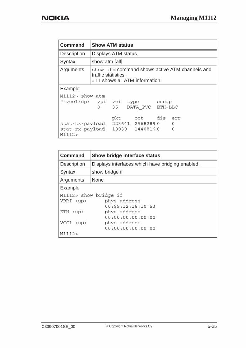
Command Show ATM status
Description Displays ATM status.
Syntax show atm [all]
Arguments show atm command shows active ATM channels andtraffic statistics.all shows all ATM information.
Example
M1112> show atm##vcc1(up) vpi vci type encap
0 35 DATA_PVC ETH-LLC
pkt oct dis errstat-tx-payload 223641 2568289 0 0stat-rx-payload 18030 1440816 0 0M1112>
Command Show bridge interface status
Description Displays interfaces which have bridging enabled.
Syntax show bridge if
Arguments None
Example
M1112> show bridge ifVBRI (up) phys-address
00:99:12:16:10:53ETH (up) phys-address
00:00:00:00:00:00VCC1 (up) phys-address
00:00:00:00:00:00M1112>
M1112 Administrator Manual
� Copyright Nokia Networks Oy C33907001SE_00 5-26
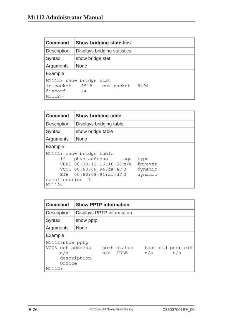
Command Show bridging statistics
Description Displays bridging statistics.
Syntax show bridge stat
Arguments None
Example
M1112> show bridge statin-packet 8518 out-packet 8494discard 24M1112>
Command Show bridging table
Description Displays bridging table.
Syntax show bridge table
Arguments None
Example
M1112> show bridge tableif phys-address age typeVBRI 00:99:12:16:10:53 n/a foreverVCC1 00:60:08:94:da:a7 0 dynamicETH 00:60:08:94:af:d7 0 dynamic
nr-of-entries 3M1112>
Command Show PPTP information
Description Displays PPTP information
Syntax show pptp
Arguments None
Example
M1112>show pptpVCC3 net-address port status host-cid peer-cid
n/a n/a IDLE n/a n/adescriptionOffice
M1112>
Managing M1112
� Copyright Nokia Networks OyC33907001SE_00 5-27
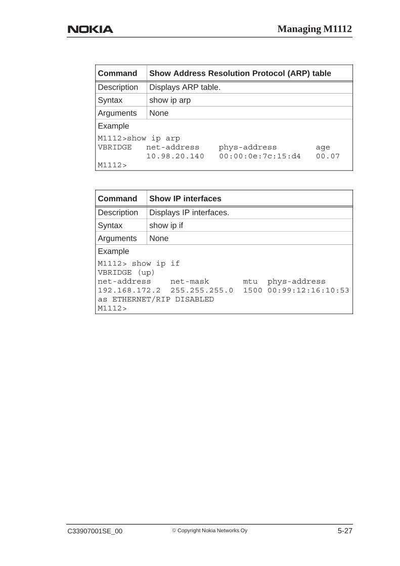
Command Show Address Resolution Protocol (ARP) table
Description Displays ARP table.
Syntax show ip arp
Arguments None
Example
M1112>show ip arpVBRIDGE net-address phys-address age
10.98.20.140 00:00:0e:7c:15:d4 00.07M1112>
Command Show IP interfaces
Description Displays IP interfaces.
Syntax show ip if
Arguments None
Example
M1112> show ip ifVBRIDGE (up)net-address net-mask mtu phys-address192.168.172.2 255.255.255.0 1500 00:99:12:16:10:53as ETHERNET/RIP DISABLEDM1112>
M1112 Administrator Manual
� Copyright Nokia Networks Oy C33907001SE_00 5-28
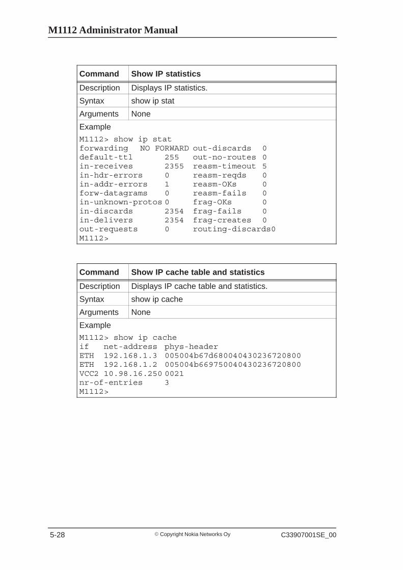
Command Show IP statistics
Description Displays IP statistics.
Syntax show ip stat
Arguments None
Example
M1112> show ip statforwarding NO FORWARD out-discards 0default-ttl 255 out-no-routes 0in-receives 2355 reasm-timeout 5in-hdr-errors 0 reasm-reqds 0in-addr-errors 1 reasm-OKs 0forw-datagrams 0 reasm-fails 0in-unknown-protos 0 frag-OKs 0in-discards 2354 frag-fails 0in-delivers 2354 frag-creates 0out-requests 0 routing-discards0M1112>
Command Show IP cache table and statistics
Description Displays IP cache table and statistics.
Syntax show ip cache
Arguments None
Example
M1112> show ip cacheif net-address phys-headerETH 192.168.1.3 005004b67d680040430236720800ETH 192.168.1.2 005004b669750040430236720800VCC2 10.98.16.250 0021nr-of-entries 3M1112>

Managing M1112
� Copyright Nokia Networks OyC33907001SE_00 5-29
Command Show IP routing table
Description Displays IP routing table.
Syntax show ip route
Arguments None
Example
M1112>show ip route
VBRIDGE
route-dest route-mask netxthop tag
10.98.20.255255.255.255.255 255.255.255.255BCAST
10.98.20.150255.255.255.255 10.98.20.150 IFACE
10.98.20.0 255.255.255.0 10.98.20.150 LOCAL
MNGTVCC
route-dest route-mask netxthop tag
10.98.9.0 255.255.255.0 10.98.5.200 RIP
10.98.5.255 255.255.255.255 255.255.255.255BCAST
10.98.5.100 255.255.255.255 10.98.5.100 IFACE
10.98.5.0 255.255.255.0 10.98.5.100 LOCAL
ETH
route-dest route-mask netxthop tag
10.98.0.255 255.255.255.255 255.255.255.255BCAST
10.98.0.254 255.255.255.255 10.98.0.254 IFACE
10.98.0.0 255.255.255.0 10.98.0.154 LOCAL
VCC3
route-dest route-mask netxthop tag
11.22.20.255255.255.255.255 255.255.255.255BCAST
11.22.20.108255.255.255.255 11.22.20.108 IFACE
11.22.20.0 255.255.255.0 11.22.20.108 LOCAL
0.0.0.0 0.0.0.0 11.22.20.1 STAT
M1112>

M1112 Administrator Manual
� Copyright Nokia Networks Oy C33907001SE_00 5-30
Command Show Internet Control Message Protocol statistics
Description Displays ICMP statistics.
Syntax show ip icmp
Arguments None
Example
M1112> show ip icmpin-msgs 23 out-msgs 23in-errors 0 out-errors 0in-dest-unreachs 0 out-dest-unreachs 0in-time-excds 0 out-time-excds 0in-parm-probs 0 out-parm-probs 0in-src-quenchs 0 out-src-quenchs 0in-redirects 0 out-redirects 0in-echos 23 out-echos 23in-echo-reps 0 out-echo-reps 0in-timestamps 0 out-timestamps 0in-timestamp-reps 0 out-timestamp-reps 0in-addr-masks 0 out-addr-masks 0in-addr-mask-reps 0 out-addr-mask-reps 0M1112>
Command Show User Datagram Protocol statistics
Description Displays UDP statistics.
Syntax show ip udp
Arguments None
Example
M1112> show ip udpin-datagrams 0 in-errors 0no-ports 0 out-datagrams 0M1112>
Managing M1112
� Copyright Nokia Networks OyC33907001SE_00 5-31
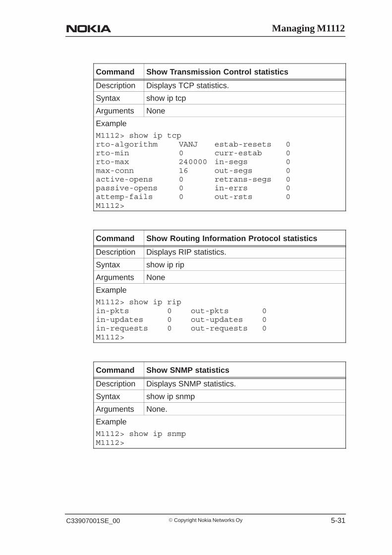
Command Show Transmission Control statistics
Description Displays TCP statistics.
Syntax show ip tcp
Arguments None
Example
M1112> show ip tcprto-algorithm VANJ estab-resets 0rto-min 0 curr-estab 0rto-max 240000 in-segs 0max-conn 16 out-segs 0active-opens 0 retrans-segs 0passive-opens 0 in-errs 0attemp-fails 0 out-rsts 0M1112>
Command Show Routing Information Protocol statistics
Description Displays RIP statistics.
Syntax show ip rip
Arguments None
Example
M1112> show ip ripin-pkts 0 out-pkts 0in-updates 0 out-updates 0in-requests 0 out-requests 0M1112>
Command Show SNMP statistics
Description Displays SNMP statistics.
Syntax show ip snmp
Arguments None.
Example
M1112> show ip snmpM1112>
M1112 Administrator Manual
� Copyright Nokia Networks Oy C33907001SE_00 5-32
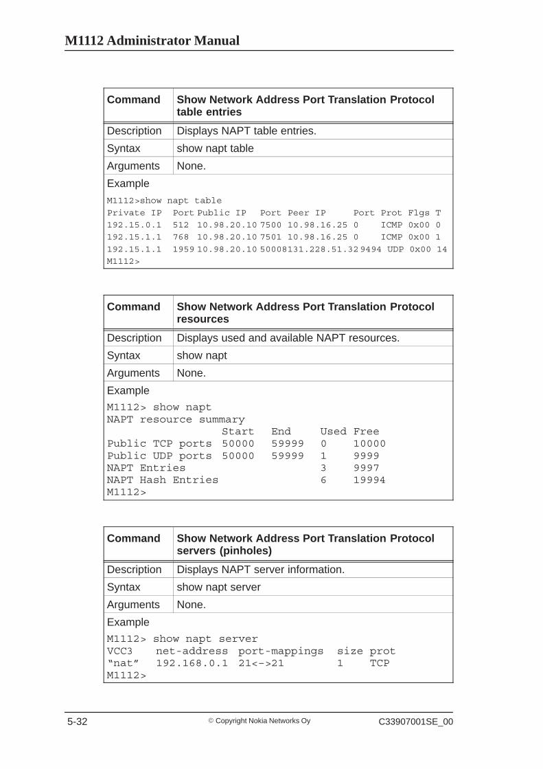
Command Show Network Address Port Translation Protocoltable entries
Description Displays NAPT table entries.
Syntax show napt table
Arguments None.
Example
M1112>show napt table
Private IP Port Public IP Port Peer IP Port Prot Flgs T
192.15.0.1 512 10.98.20.10 7500 10.98.16.25 0 ICMP 0x00 0
192.15.1.1 768 10.98.20.10 7501 10.98.16.25 0 ICMP 0x00 1
192.15.1.1 1959 10.98.20.10 50008131.228.51.329494 UDP 0x00 14
M1112>
Command Show Network Address Port Translation Protocolresources
Description Displays used and available NAPT resources.
Syntax show napt
Arguments None.
Example
M1112> show naptNAPT resource summary
Start End Used FreePublic TCP ports 50000 59999 0 10000Public UDP ports 50000 59999 1 9999NAPT Entries 3 9997NAPT Hash Entries 6 19994M1112>
Command Show Network Address Port Translation Protocolservers (pinholes)
Description Displays NAPT server information.
Syntax show napt server
Arguments None.
Example
M1112> show napt serverVCC3 net-address port-mappings size prot“nat” 192.168.0.1 21<–>21 1 TCPM1112>
Managing M1112
� Copyright Nokia Networks OyC33907001SE_00 5-33
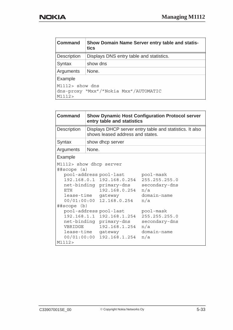
Command Show Domain Name Server entry table and statis-tics
Description Displays DNS entry table and statistics.
Syntax show dns
Arguments None.
Example
M1112> show dnsdns-proxy “Mxx”/”Nokia Mxx”/AUTOMATICM1112>
Command Show Dynamic Host Configuration Protocol serverentry table and statistics
Description Displays DHCP server entry table and statistics. It alsoshows leased address and states.
Syntax show dhcp server
Arguments None.
Example
M1112> show dhcp server##scope (a)
pool-address pool-last pool-mask192.168.0.1 192.168.0.254 255.255.255.0net-binding primary-dns secondary-dnsETH 192.168.0.254 n/alease-time gateway domain-name00/01:00:00 12.168.0.254 n/a
##scope (b)pool-address pool-last pool-mask192.168.1.1 192.168.1.254 255.255.255.0net-binding primary-dns secondary-dnsVBRIDGE 192.168.1.254 n/alease-time gateway domain-name00/01:00:00 192.168.1.254 n/a
M1112>
M1112 Administrator Manual
� Copyright Nokia Networks Oy C33907001SE_00 5-34
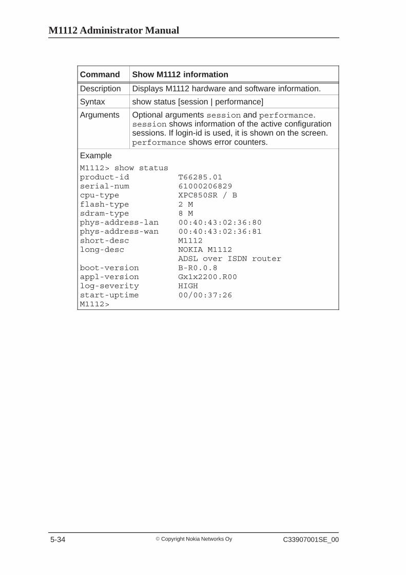
Command Show M1112 information
Description Displays M1112 hardware and software information.
Syntax show status [session | performance]
Arguments Optional arguments session and performance.session shows information of the active configurationsessions. If login-id is used, it is shown on the screen.performance shows error counters.
Example
M1112> show statusproduct-id T66285.01serial-num 61000206829cpu-type XPC850SR / Bflash-type 2 Msdram-type 8 Mphys-address-lan 00:40:43:02:36:80phys-address-wan 00:40:43:02:36:81short-desc M1112long-desc NOKIA M1112
ADSL over ISDN routerboot-version B-R0.0.8appl-version Gx1x2200.R00log-severity HIGHstart-uptime 00/00:37:26M1112>
Managing M1112
� Copyright Nokia Networks OyC33907001SE_00 5-35
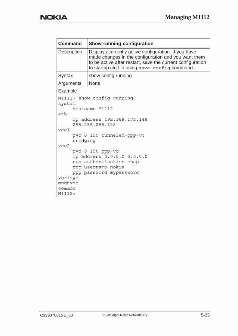
Command Show running configuration
Description Displays currently active configuration. If you havemade changes in the configuration and you want themto be active after restart, save the current configurationto startup.cfg file using save config command.
Syntax show config running
Arguments None
Example
M1112> show config runningsystem
hostname M1112eth
ip address 192.168.172.148255.255.255.128
vcc1pvc 0 155 tunneled-ppp-vcbridging
vcc2pvc 0 156 ppp-vcip address 0.0.0.0 0.0.0.0ppp authentication chapppp username nokiappp password mypassword
vbridgemngtvcccommonM1112>
M1112 Administrator Manual
� Copyright Nokia Networks Oy C33907001SE_00 5-36
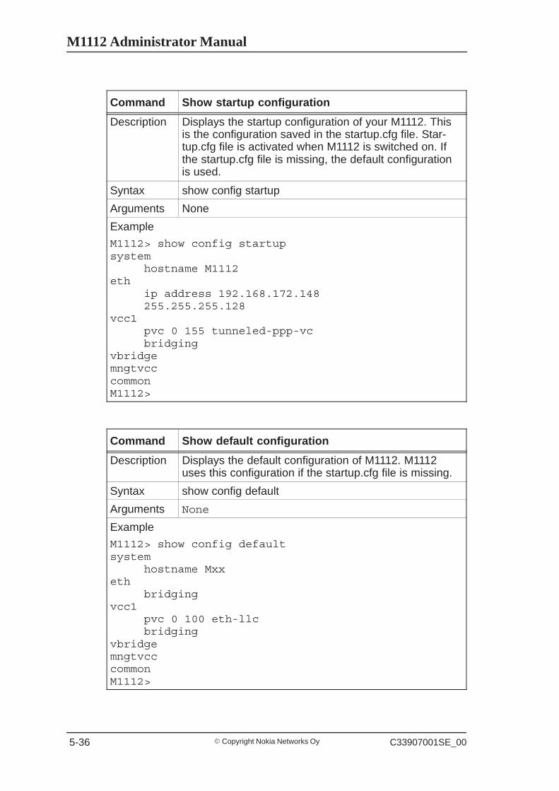
Command Show startup configuration
Description Displays the startup configuration of your M1112. Thisis the configuration saved in the startup.cfg file. Star-tup.cfg file is activated when M1112 is switched on. Ifthe startup.cfg file is missing, the default configurationis used.
Syntax show config startup
Arguments None
Example
M1112> show config startupsystem
hostname M1112eth
ip address 192.168.172.148255.255.255.128
vcc1pvc 0 155 tunneled-ppp-vcbridging
vbridgemngtvcccommonM1112>
Command Show default configuration
Description Displays the default configuration of M1112. M1112uses this configuration if the startup.cfg file is missing.
Syntax show config default
Arguments None
Example
M1112> show config defaultsystem
hostname Mxxeth
bridgingvcc1
pvc 0 100 eth-llcbridging
vbridgemngtvcccommonM1112>
Managing M1112
� Copyright Nokia Networks OyC33907001SE_00 5-37
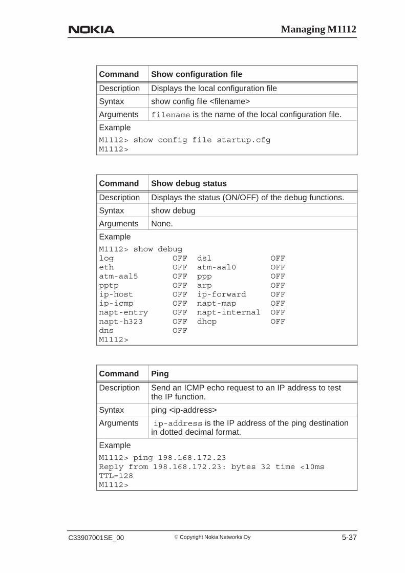
Command Show configuration file
Description Displays the local configuration file
Syntax show config file <filename>
Arguments filename is the name of the local configuration file.
Example
M1112> show config file startup.cfgM1112>
Command Show debug status
Description Displays the status (ON/OFF) of the debug functions.
Syntax show debug
Arguments None.
Example
M1112> show debuglog OFF dsl OFFeth OFF atm-aal0 OFFatm-aal5 OFF ppp OFFpptp OFF arp OFFip-host OFF ip-forward OFFip-icmp OFF napt-map OFFnapt-entry OFF napt-internal OFFnapt-h323 OFF dhcp OFFdns OFFM1112>
Command Ping
Description Send an ICMP echo request to an IP address to testthe IP function.
Syntax ping <ip-address>
Arguments ip-address is the IP address of the ping destinationin dotted decimal format.
Example
M1112> ping 198.168.172.23Reply from 198.168.172.23: bytes 32 time <10msTTL=128M1112>

M1112 Administrator Manual
� Copyright Nokia Networks Oy C33907001SE_00 5-38
Command ATMping
Description Sends five OAM F5 loopback cells to the specified VPI/VCI destination with a 5 second total timeout interval.You can use ATMping to test the ATM connection.
Syntax atmping <vpi> <vci> <range>
Arguments vpi is the Virtual Path Identifier and vci is the VirtualChannel Identifier of the ATM channel you want to test.vpi values are integers (0...255).vci values are integers (0...65535)range values are segment and end-to-end depend-ing whether you want to test the first segment of theATM connection or the end-to-end connection.
Example
M1112> atm ping 0 23 segmentreply asserted roundtrip time = 4.20 msM1112>
The debug commands are used to solve difficult problem situations.The debugging can be switched off with the following command.Other debugging commands are not handled in this manual.
Command Switch off debug
Description Switches all debug operations off. To quit debugging,write no debug all on the screen regardless of what isbeing printed on the screen.
Syntax no debug all
Arguments no switches debugging off.
Example
M1112> no debug allM1112>
Managing M1112
� Copyright Nokia Networks OyC33907001SE_00 5-39
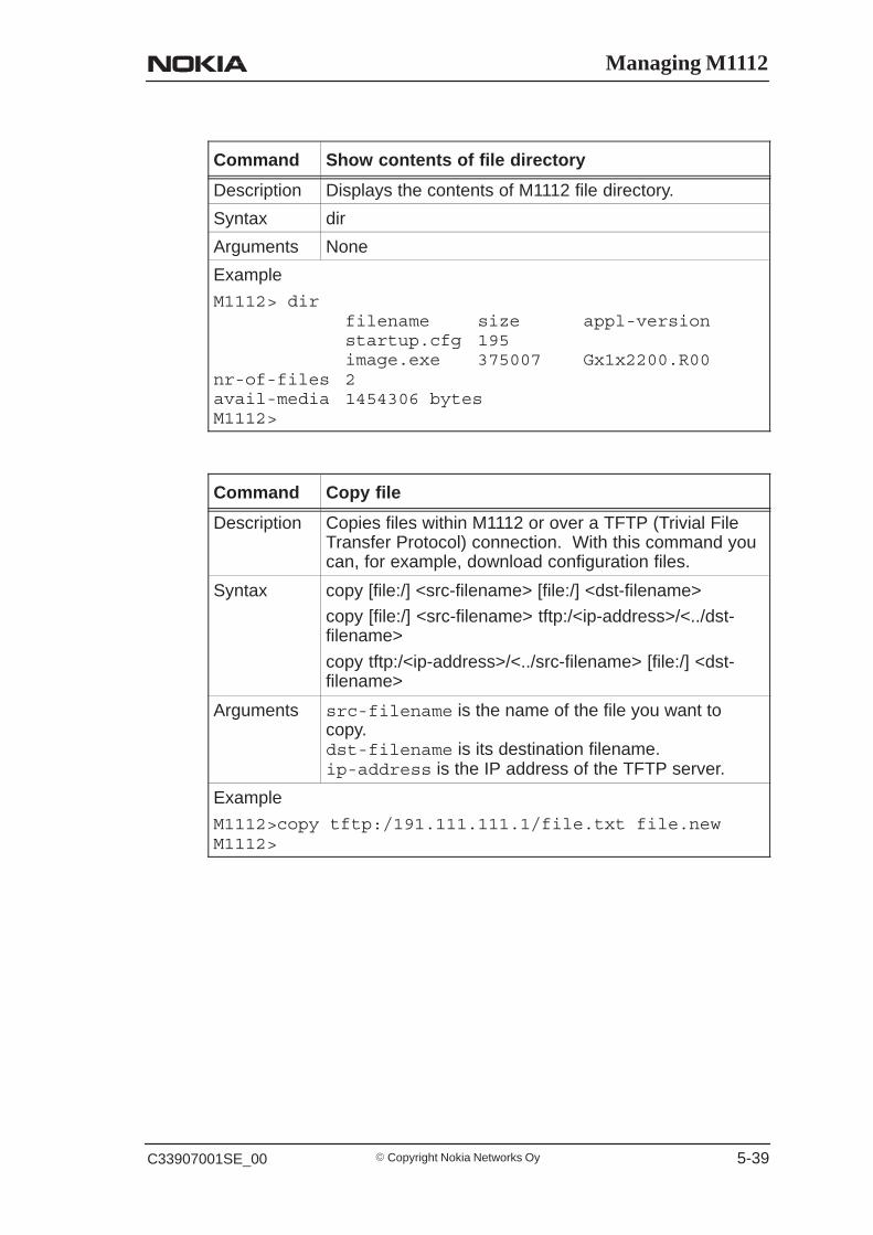
Command Show contents of file directory
Description Displays the contents of M1112 file directory.
Syntax dir
Arguments None
Example
M1112> dirfilename size appl-versionstartup.cfg 195image.exe 375007 Gx1x2200.R00
nr-of-files 2avail-media 1454306 bytesM1112>
Command Copy file
Description Copies files within M1112 or over a TFTP (Trivial FileTransfer Protocol) connection. With this command youcan, for example, download configuration files.
Syntax copy [file:/] <src-filename> [file:/] <dst-filename>
copy [file:/] <src-filename> tftp:/<ip-address>/<../dst-filename>
copy tftp:/<ip-address>/<../src-filename> [file:/] <dst-filename>
Arguments src-filename is the name of the file you want tocopy.dst-filename is its destination filename.ip-address is the IP address of the TFTP server.
Example
M1112>copy tftp:/191.111.111.1/file.txt file.newM1112>
M1112 Administrator Manual
� Copyright Nokia Networks Oy C33907001SE_00 5-40
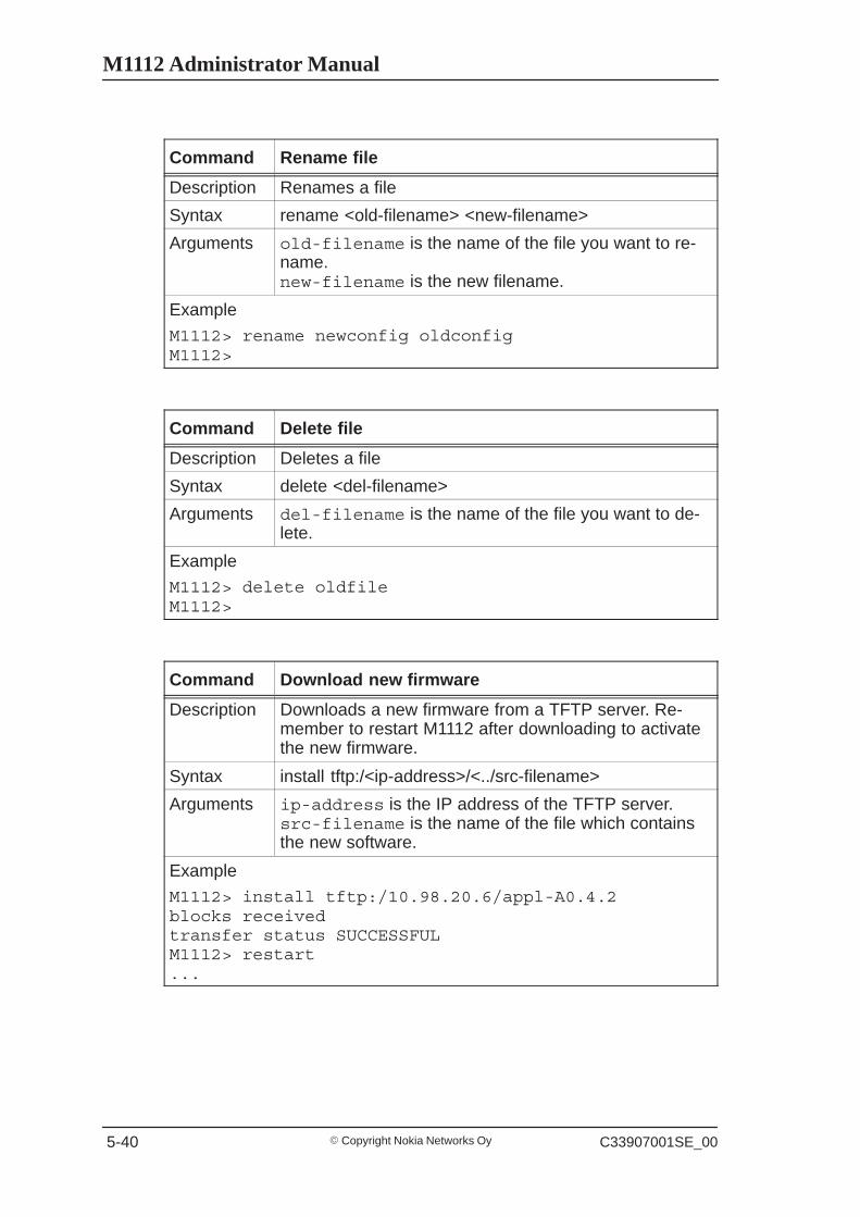
Command Rename file
Description Renames a file
Syntax rename <old-filename> <new-filename>
Arguments old-filename is the name of the file you want to re-name.new-filename is the new filename.
Example
M1112> rename newconfig oldconfigM1112>
Command Delete file
Description Deletes a file
Syntax delete <del-filename>
Arguments del-filename is the name of the file you want to de-lete.
Example
M1112> delete oldfileM1112>
Command Download new firmware
Description Downloads a new firmware from a TFTP server. Re-member to restart M1112 after downloading to activatethe new firmware.
Syntax install tftp:/<ip-address>/<../src-filename>
Arguments ip-address is the IP address of the TFTP server.src-filename is the name of the file which containsthe new software.
Example
M1112> install tftp:/10.98.20.6/appl-A0.4.2blocks receivedtransfer status SUCCESSFULM1112> restart...

Managing M1112
� Copyright Nokia Networks OyC33907001SE_00 5-41
Command Execute a command batch
Description Executes a custom command batch.
Syntax script <batch-filename>
Arguments batch-filename is the name of the file in which youwant to execute.
Example
M1112>script swap.batM1112>
Command Save log to file
Description Saves log to a file.
Syntax save log file<log-filename>
Arguments log-filename is the name of the file in which youwant to save the log.
Example
M1112>save log file log.txtM1112>
Command Save log to a default file
Description Saves log with a default file name (default.log).
Syntax save log default
Arguments None
Example
M1112>save log defaultM1112>

M1112 Administrator Manual
� Copyright Nokia Networks Oy C33907001SE_00 5-42
Command Save configuration to file
Description Saves the configuration to a file.
Syntax save config {file<filename> | startup | user}
Arguments filename is the name of the file in which you want tosave the configuration.startup-config argument saves the configurationinto a startup.cfg file.user saves the user configuration.
Example
M1112>save config startup-configM1112>
Command Restore configuration
Description Restores the default or user configuration. You musthave the admin privileges to issue this command. Re-start your M1112 after you have issued this command.
Syntax restore config {default | user}
Arguments default argument restores the default configuration ofM1112.user argument restores the user configuration. Theuser configuration can be made with admin rights only.
Example
M1112>restore config defaultM1112>
Command Clear counters
Description Clears the statistics counters.
Syntax clear {log | eth | atm | bridge | ppp | ip}
Arguments log argument rewinds the diagnostic log to the begin-ning of the log file.eth argument clears the Ethernet statistics counters.atm argument clears the ATM statistics counters.bridge argument clears the bridging counters.ppp argument clears the PPP counters.ip argument clears the IP statistics counters.
Example
M1112> clear logM1112>

Managing M1112
� Copyright Nokia Networks OyC33907001SE_00 5-43
Command Reset subsystem
Description Resets subsystems.
Syntax reset {log | dsl | ppp [vcc-id] | arp | bridge | napt}
Arguments log resets the diagnostic log subsystem.dsl resets the DSL subsystem. The DSL connectionwill be re-established.ppp resets the whole PPP subsystem. The PPP con-nection will be re-establihed. If you provide a VCCnumber (vcc-id), only that connection will be reseted.arp clears the ARP table.bridge clears the bridge table.napt resets the NAPT subsystem.
Example
M1112> reset bridgeM1112>
Command Logout
Description Logs out from the command line interface.
Syntax logout
Arguments None
Example
M1112>logout
Command Fast restart M1112
Description Restarts M1112 software.
Syntax reload
Arguments None
Example
M1112>reloadin progress...
M1112 Administrator Manual
� Copyright Nokia Networks Oy C33907001SE_00 5-44
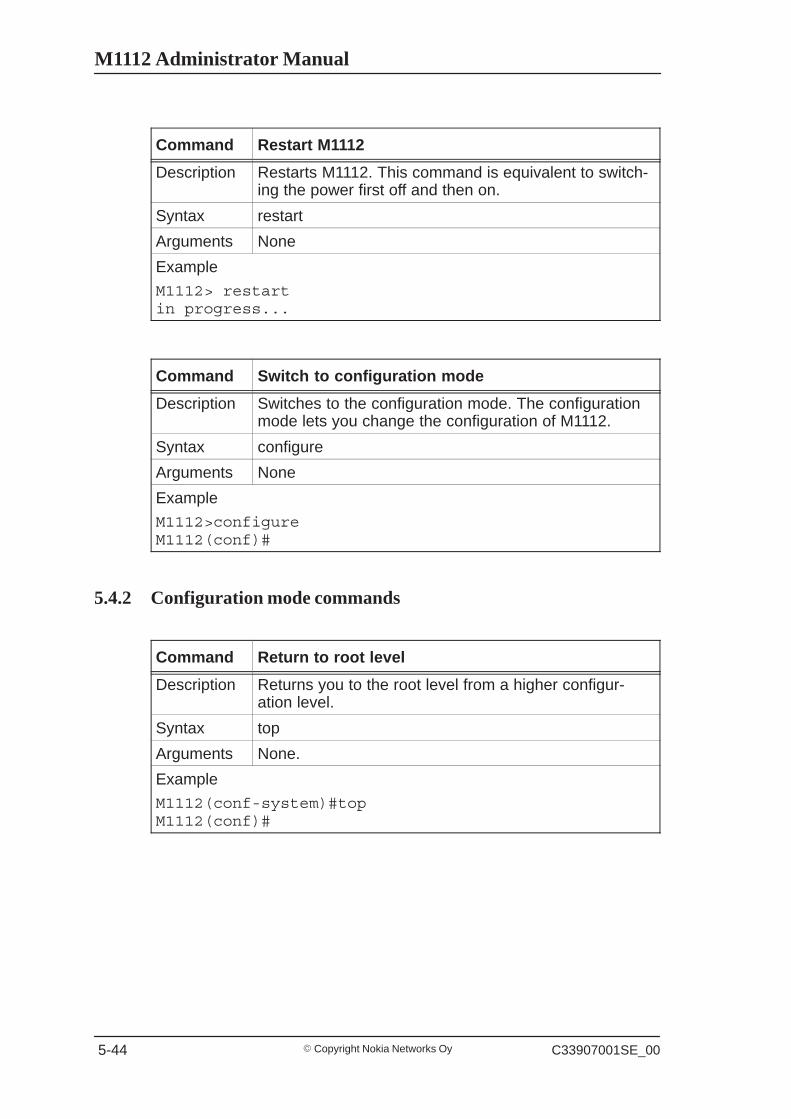
Command Restart M1112
Description Restarts M1112. This command is equivalent to switch-ing the power first off and then on.
Syntax restart
Arguments None
Example
M1112> restartin progress...
Command Switch to configuration mode
Description Switches to the configuration mode. The configurationmode lets you change the configuration of M1112.
Syntax configure
Arguments None
Example
M1112>configureM1112(conf)#
5.4.2 Configuration mode commands
Command Return to root level
Description Returns you to the root level from a higher configur-ation level.
Syntax top
Arguments None.
Example
M1112(conf-system)#topM1112(conf)#
Managing M1112
� Copyright Nokia Networks OyC33907001SE_00 5-45
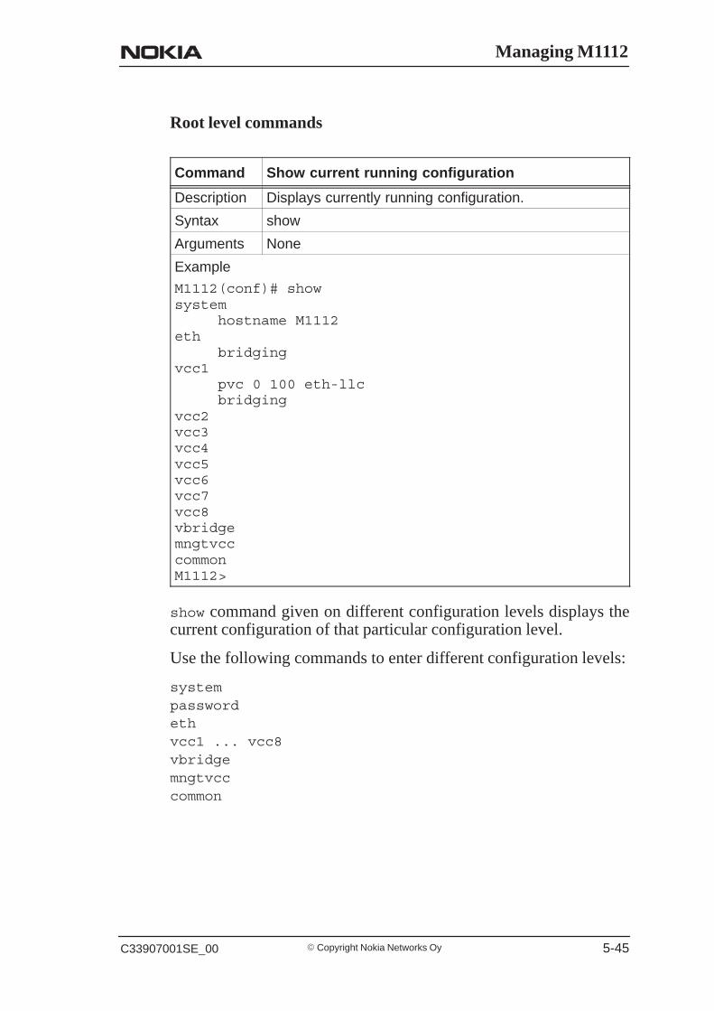
Root level commands
Command Show current running configuration
Description Displays currently running configuration.
Syntax show
Arguments None
Example
M1112(conf)# showsystem
hostname M1112eth
bridgingvcc1
pvc 0 100 eth-llcbridging
vcc2vcc3vcc4vcc5vcc6vcc7vcc8vbridgemngtvcccommonM1112>
show command given on different configuration levels displays thecurrent configuration of that particular configuration level.
Use the following commands to enter different configuration levels:
systempasswordethvcc1 ... vcc8vbridgemngtvcccommon

M1112 Administrator Manual
� Copyright Nokia Networks Oy C33907001SE_00 5-46
System level commands
Command Assign hostname
Description Assigns a hostname to M1112.
Syntax hostname <name-string>
Arguments name-string is an ASCII string of maximum of 32characters.
Example
M1112(conf-system)#hostname nokianokia(conf-system)#
Command Set configuration session timeout
Description Sets a timeout for a management session.
Syntax timeout <value>
Arguments value is a time from 1 to 255 minutes.
Example
M1112(conf-system)#timeout 10nokia(conf-system)#
Managing M1112
� Copyright Nokia Networks OyC33907001SE_00 5-47
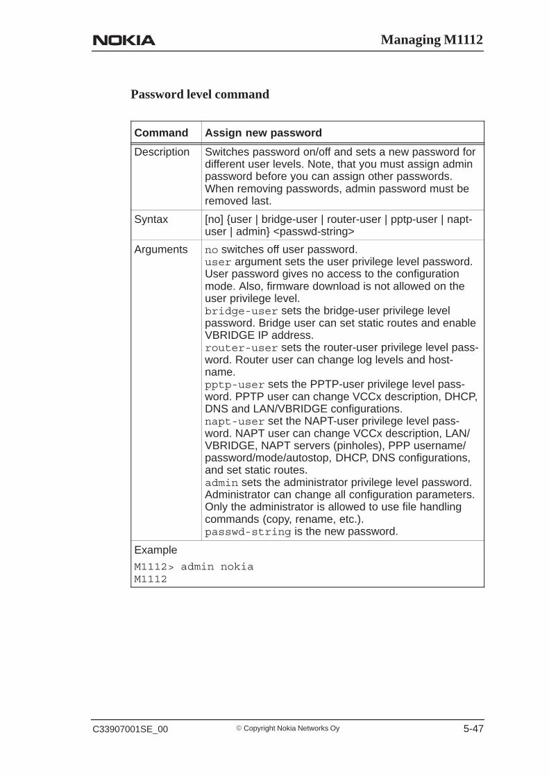
Password level command
Command Assign new password
Description Switches password on/off and sets a new password fordifferent user levels. Note, that you must assign adminpassword before you can assign other passwords.When removing passwords, admin password must beremoved last.
Syntax [no] {user | bridge-user | router-user | pptp-user | napt-user | admin} <passwd-string>
Arguments no switches off user password.user argument sets the user privilege level password.User password gives no access to the configurationmode. Also, firmware download is not allowed on theuser privilege level.bridge-user sets the bridge-user privilege levelpassword. Bridge user can set static routes and enableVBRIDGE IP address.router-user sets the router-user privilege level pass-word. Router user can change log levels and host-name.pptp-user sets the PPTP-user privilege level pass-word. PPTP user can change VCCx description, DHCP,DNS and LAN/VBRIDGE configurations.napt-user set the NAPT-user privilege level pass-word. NAPT user can change VCCx description, LAN/VBRIDGE, NAPT servers (pinholes), PPP username/password/mode/autostop, DHCP, DNS configurations,and set static routes.admin sets the administrator privilege level password.Administrator can change all configuration parameters.Only the administrator is allowed to use file handlingcommands (copy, rename, etc.).passwd-string is the new password.
Example
M1112> admin nokiaM1112

M1112 Administrator Manual
� Copyright Nokia Networks Oy C33907001SE_00 5-48
Ethernet level commands
Command Switch on/off bridging
Description Switches on/off bridging.
Syntax [no] bridging
Arguments no switches bridging off.
Example
M1112(conf-eth)#bridgingM1112(conf-eth)#
Command Switch on/off IP function in Ethernet interface
Description Switches on/off IP function in the Ethernet interface.
Syntax [no] ip address <ip-address> <ip-mask>
Arguments no switches IP function off.ip-address is the IP address you want to assign tothe Ethernet interface.ip-mask is the subnet mask.
Example
M1112(conf-eth)#ip address 192.168.132.11255.255.255.0M1112(conf-eth)#
Command Switch on/off RIP send function in Ethernet inter-face
Description Switches on/off RIP send function. When enabledM1112 sends Routing Information Protocol messagesto other routers.
Syntax [no] ip rip-send {rip-send-mode}
Arguments no switches rip-send function off.v1 send-mode selects RIP version 1.v2 send-mode selects RIP version 2.compatible-v1 send-mode selects the sending ofRIPv2 packets using broadcast.
Example
M1112(conf-eth)#ip rip-send v1M1112(conf-eth)#
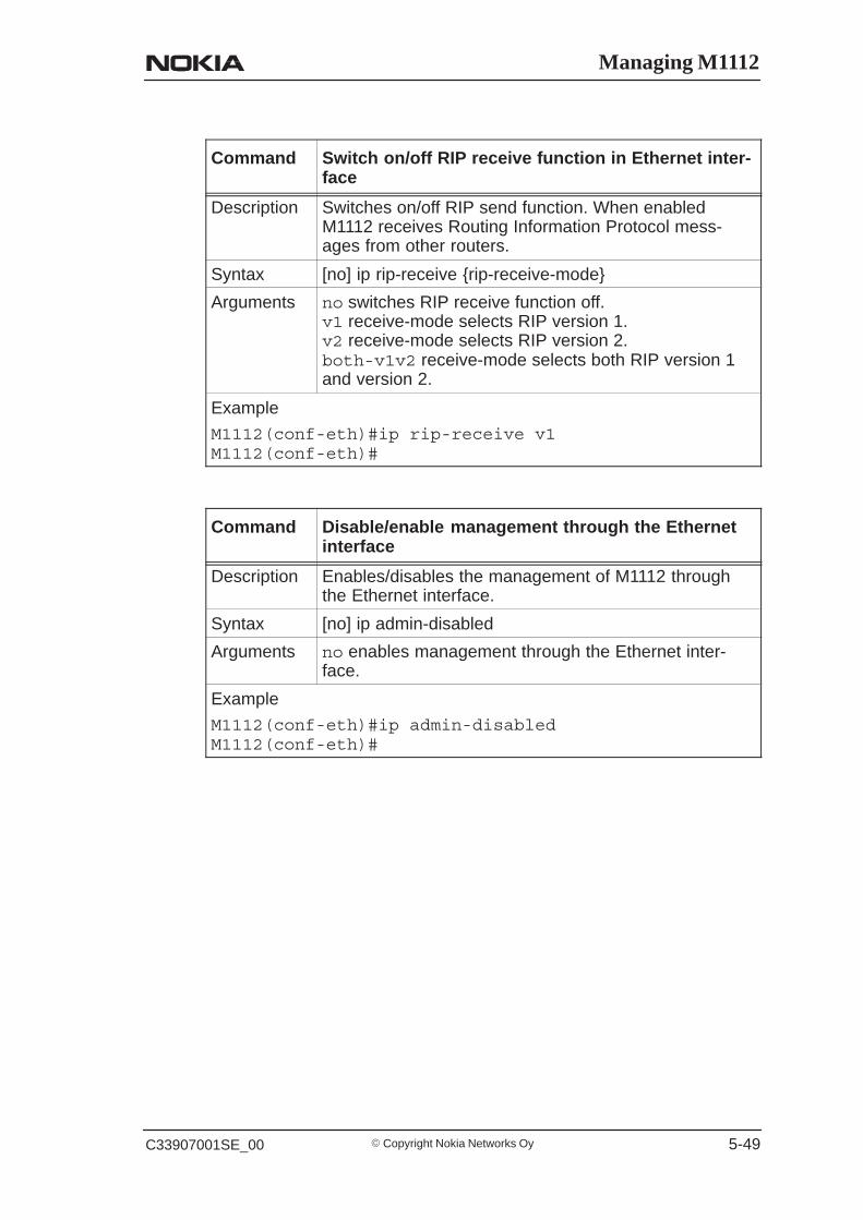
Managing M1112
� Copyright Nokia Networks OyC33907001SE_00 5-49
Command Switch on/off RIP receive function in Ethernet inter-face
Description Switches on/off RIP send function. When enabledM1112 receives Routing Information Protocol mess-ages from other routers.
Syntax [no] ip rip-receive {rip-receive-mode}
Arguments no switches RIP receive function off.v1 receive-mode selects RIP version 1.v2 receive-mode selects RIP version 2.both-v1v2 receive-mode selects both RIP version 1and version 2.
Example
M1112(conf-eth)#ip rip-receive v1M1112(conf-eth)#
Command Disable/enable management through the Ethernetinterface
Description Enables/disables the management of M1112 throughthe Ethernet interface.
Syntax [no] ip admin-disabled
Arguments no enables management through the Ethernet inter-face.
Example
M1112(conf-eth)#ip admin-disabledM1112(conf-eth)#

M1112 Administrator Manual
� Copyright Nokia Networks Oy C33907001SE_00 5-50
VCC (ATM channel) commands
Command Activate ATM channel
Description Activates an ATM channel and sets the encapsulationfor that channel.
Syntax [no] pvc <vpi> <vci> <encap>
Arguments no deactivates the ATM channel.vpi is the Virtual Path Identifier of the ATM channel.Possible values are 0...255.vci is the Virtual Channel Identifier of the ATM chan-nel. Possible values are 0...65535.encap is the encapsulation of the ATM channel. Theencapsulations are auto-llc, eth-llc, ip-llc,ppp-vc, and tunneled-ppp-vc. auto-llc en-capsulates the routed packets in ip-llc and the bridgedpackets in eth-llc.
Example
M1112(conf-vccx)#pvc 0 100 ip-llcM1112(conf-vccx)#
Command Switch on/off bridging
Description Switches bridging on/off on the specified ATM channel.
Syntax [no] bridging
Arguments no switches off bridging.
Example
M1112(conf-vccx)#bridgingM1112(conf-vccx)#

Managing M1112
� Copyright Nokia Networks OyC33907001SE_00 5-51
Command Switch on/off PPP authentication
Description Switches PPP authentication on/off on the specifiedATM channel.
Syntax [no] ppp authentication {mode}
Arguments no switches off PPP authentication.chap mode selects Challenge Handshake Authentica-tion Protocol.pap mode selects Password Authentication Protocol.both-chap-pap mode selects both authenticationprotocols.
Example
M1112(conf-vccx)#ppp authentication chapM1112(conf-vccx)#
Command Set PPP username
Description Sets the username used in PPP authentication.
Syntax [no] ppp username <name-string>
Arguments no deletes PPP username.name-string is your PPP username. The maximumlength of the username is 15 characters.
Example
M1112(conf-vccx)#ppp username ut32ajM1112(conf-vccx)#
Command Set PPP password
Description Sets the password used in PPP authentication.
Syntax [no] ppp password <passwd-string>
Arguments no deletes PPP password.passwd-string is the PPP password. The passwordmust be 4...15 characters long.
Example
M1112(conf-vccx)#ppp password jfddslfjM1112(conf-vccx)#
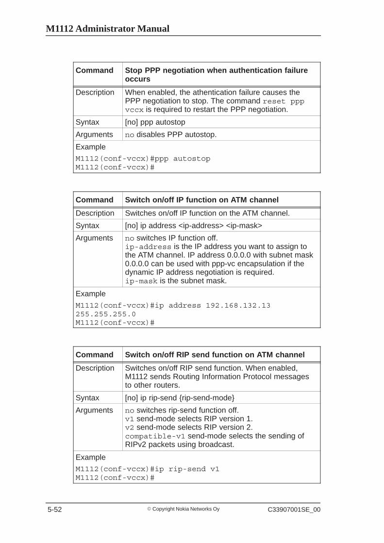
M1112 Administrator Manual
� Copyright Nokia Networks Oy C33907001SE_00 5-52
Command Stop PPP negotiation when authentication failureoccurs
Description When enabled, the athentication failure causes thePPP negotiation to stop. The command reset pppvccx is required to restart the PPP negotiation.
Syntax [no] ppp autostop
Arguments no disables PPP autostop.
Example
M1112(conf-vccx)#ppp autostopM1112(conf-vccx)#
Command Switch on/off IP function on ATM channel
Description Switches on/off IP function on the ATM channel.
Syntax [no] ip address <ip-address> <ip-mask>
Arguments no switches IP function off.ip-address is the IP address you want to assign tothe ATM channel. IP address 0.0.0.0 with subnet mask0.0.0.0 can be used with ppp-vc encapsulation if thedynamic IP address negotiation is required.ip-mask is the subnet mask.
Example
M1112(conf-vccx)#ip address 192.168.132.13255.255.255.0M1112(conf-vccx)#
Command Switch on/off RIP send function on ATM channel
Description Switches on/off RIP send function. When enabled,M1112 sends Routing Information Protocol messagesto other routers.
Syntax [no] ip rip-send {rip-send-mode}
Arguments no switches rip-send function off.v1 send-mode selects RIP version 1.v2 send-mode selects RIP version 2.compatible-v1 send-mode selects the sending ofRIPv2 packets using broadcast.
Example
M1112(conf-vccx)#ip rip-send v1M1112(conf-vccx)#
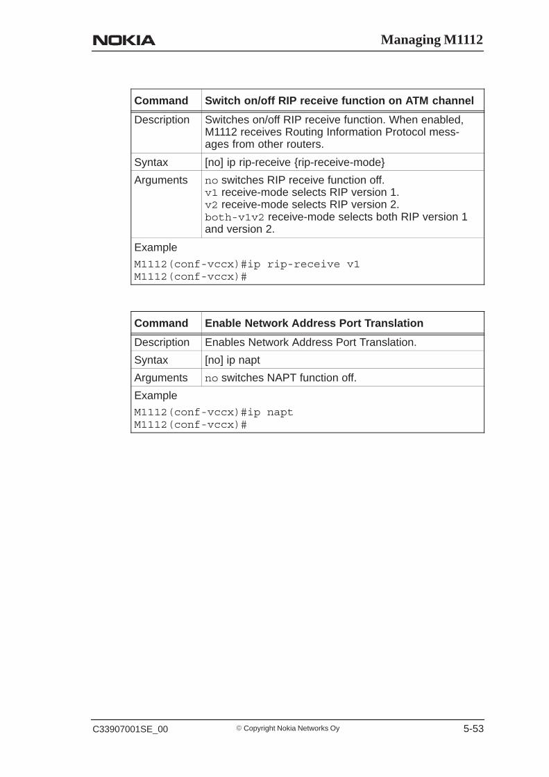
Managing M1112
� Copyright Nokia Networks OyC33907001SE_00 5-53
Command Switch on/off RIP receive function on ATM channel
Description Switches on/off RIP receive function. When enabled,M1112 receives Routing Information Protocol mess-ages from other routers.
Syntax [no] ip rip-receive {rip-receive-mode}
Arguments no switches RIP receive function off.v1 receive-mode selects RIP version 1.v2 receive-mode selects RIP version 2.both-v1v2 receive-mode selects both RIP version 1and version 2.
Example
M1112(conf-vccx)#ip rip-receive v1M1112(conf-vccx)#
Command Enable Network Address Port Translation
Description Enables Network Address Port Translation.
Syntax [no] ip napt
Arguments no switches NAPT function off.
Example
M1112(conf-vccx)#ip naptM1112(conf-vccx)#

M1112 Administrator Manual
� Copyright Nokia Networks Oy C33907001SE_00 5-54
Command Set server support entry
Description Sets a NAPT server support entry.
Syntax [no] ip server-napt <pool-string><hidden-address><hidden-pool-base> <public-pool-base> <pool-size><protocol-id>
Arguments no deletes pinhole entry.pool-string identifies the server entry.hidden-address is the address of the local server forwhich the pinhole is made.hidden-pool-base is the start of the local portrange.public-pool-base is the start of the external portrange.pool-size is the size of the port range.protocol-id is the protocol allowed through the pin-hole. Available protocols are: UDP, TCP, PPTP-GRE,and ESP-IPSEC
Example:When hidden-pool-base is 80, public-pool-base is 80 and pool-size is 1, traffic coming to exter-nal port (WAN port) 80 will be mapped to internal port80.
Example
M1112(conf-vccx)#ip server-napt web_server192.168.1.100 80 80 1 tcpM1112(conf-vccx)#
Command Disable/enable management through the ATM chan-nel
Description Enables/disables the management of M1112 throughthe ATM channel.
Syntax [no] ip admin-disabled
Arguments no enables management through the ATM channel.
Example
M1112(conf-vccx)#ip admin-disabledM1112(conf-vccx)#
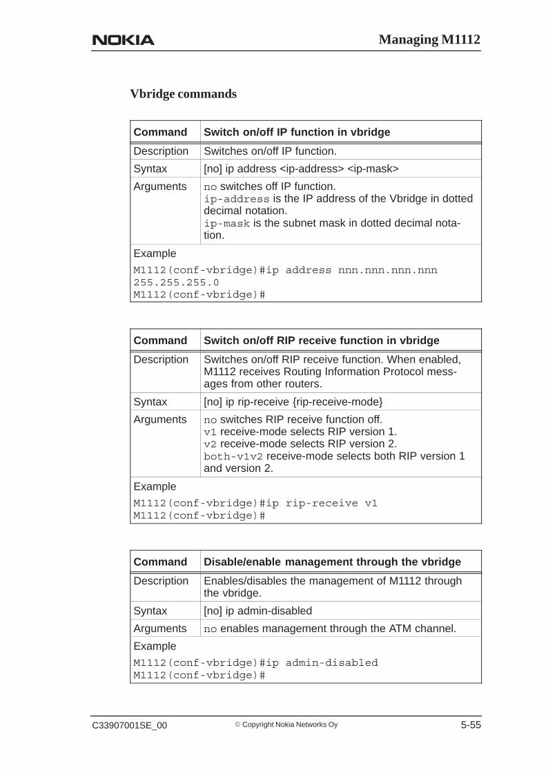
Managing M1112
� Copyright Nokia Networks OyC33907001SE_00 5-55
Vbridge commands
Command Switch on/off IP function in vbridge
Description Switches on/off IP function.
Syntax [no] ip address <ip-address> <ip-mask>
Arguments no switches off IP function.ip-address is the IP address of the Vbridge in dotteddecimal notation.ip-mask is the subnet mask in dotted decimal nota-tion.
Example
M1112(conf-vbridge)#ip address nnn.nnn.nnn.nnn255.255.255.0M1112(conf-vbridge)#
Command Switch on/off RIP receive function in vbridge
Description Switches on/off RIP receive function. When enabled,M1112 receives Routing Information Protocol mess-ages from other routers.
Syntax [no] ip rip-receive {rip-receive-mode}
Arguments no switches RIP receive function off.v1 receive-mode selects RIP version 1.v2 receive-mode selects RIP version 2.both-v1v2 receive-mode selects both RIP version 1and version 2.
Example
M1112(conf-vbridge)#ip rip-receive v1M1112(conf-vbridge)#
Command Disable/enable management through the vbridge
Description Enables/disables the management of M1112 throughthe vbridge.
Syntax [no] ip admin-disabled
Arguments no enables management through the ATM channel.
Example
M1112(conf-vbridge)#ip admin-disabledM1112(conf-vbridge)#

M1112 Administrator Manual
� Copyright Nokia Networks Oy C33907001SE_00 5-56
Command Switch on/off VCC-to-VCC bridging
Description Switches on/off bridging between ATM channels.
Syntax [no] interwan-bridging
Arguments no switches off bridging between ATM channels.
Example
M1112(conf-vbridge)#interwan-bridgingM1112(conf-vbridge)#
Dedicated management channel commands
Command Activate dedicated management channel
Description Activates a dedicated management channel and setsthe encapsulation for that channel.
Syntax [no] pvc <vpi> <vci> <encap>
Arguments no deactivates the ATM channel.vpi is the Virtual Path Identifier of the ATM channel.Possible values are 0...255.vci is the Virtual Channel Identifier of the ATM chan-nel. Possible values are 0...65535.encap is the encapsulation of the ATM channel. En-capsulations are ppp-vc, eth-llc, and ip-llc.
Example
M1112(conf-mngtvcc)#pvc 0 100 eth-llcM1112(conf-mngtvcc)#
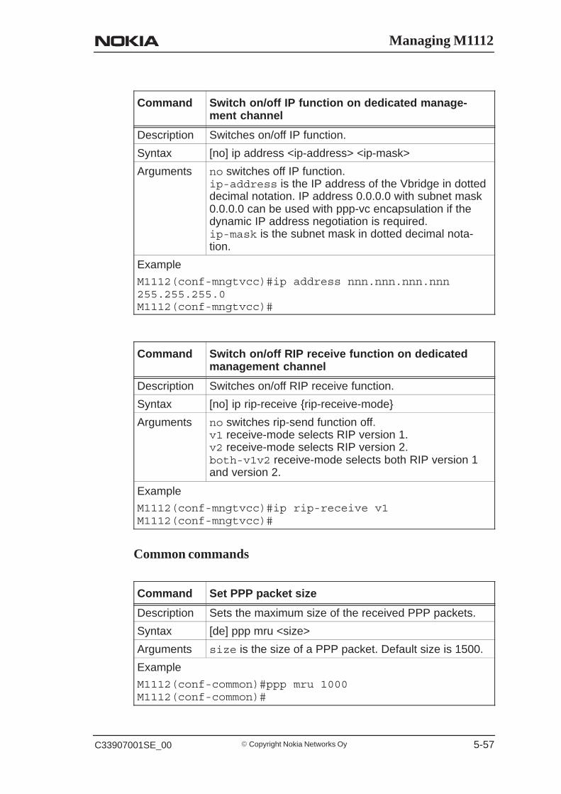
Managing M1112
� Copyright Nokia Networks OyC33907001SE_00 5-57
Command Switch on/off IP function on dedicated manage-ment channel
Description Switches on/off IP function.
Syntax [no] ip address <ip-address> <ip-mask>
Arguments no switches off IP function.ip-address is the IP address of the Vbridge in dotteddecimal notation. IP address 0.0.0.0 with subnet mask0.0.0.0 can be used with ppp-vc encapsulation if thedynamic IP address negotiation is required.ip-mask is the subnet mask in dotted decimal nota-tion.
Example
M1112(conf-mngtvcc)#ip address nnn.nnn.nnn.nnn255.255.255.0M1112(conf-mngtvcc)#
Command Switch on/off RIP receive function on dedicatedmanagement channel
Description Switches on/off RIP receive function.
Syntax [no] ip rip-receive {rip-receive-mode}
Arguments no switches rip-send function off.v1 receive-mode selects RIP version 1.v2 receive-mode selects RIP version 2.both-v1v2 receive-mode selects both RIP version 1and version 2.
Example
M1112(conf-mngtvcc)#ip rip-receive v1M1112(conf-mngtvcc)#
Common commands
Command Set PPP packet size
Description Sets the maximum size of the received PPP packets.
Syntax [de] ppp mru <size>
Arguments size is the size of a PPP packet. Default size is 1500.
Example
M1112(conf-common)#ppp mru 1000M1112(conf-common)#

M1112 Administrator Manual
� Copyright Nokia Networks Oy C33907001SE_00 5-58
Command Set PPP restart time parameter
Description Defines how long M1112 waits for the configure-requestpacket.
Syntax [de] ppp restart <time>
Arguments time in seconds.
Example
M1112(conf-common)#ppp restart 5M1112(conf-common)#
Command Set max-config parameter value
Description Defines how many times the configure-request packetwill be sent.
Syntax [de] ppp max-config <pkt-count>
Arguments pkt-count is the number of configure requestpackets, values 1...30.
Example
M1112(conf-common)#ppp max-config 10M1112(conf-common)#
Command Set max-terminate parameter value
Description Defines how many terminate-request packets will besent before M1112 decides that the connection is down.
Syntax [de] ppp max-terminate <pkt-count>
Arguments pkt-count is the number of configure requestpackets, values 1...30.
Example
M1112(conf-common)#ppp max–terminate 10M1112(conf-common)#
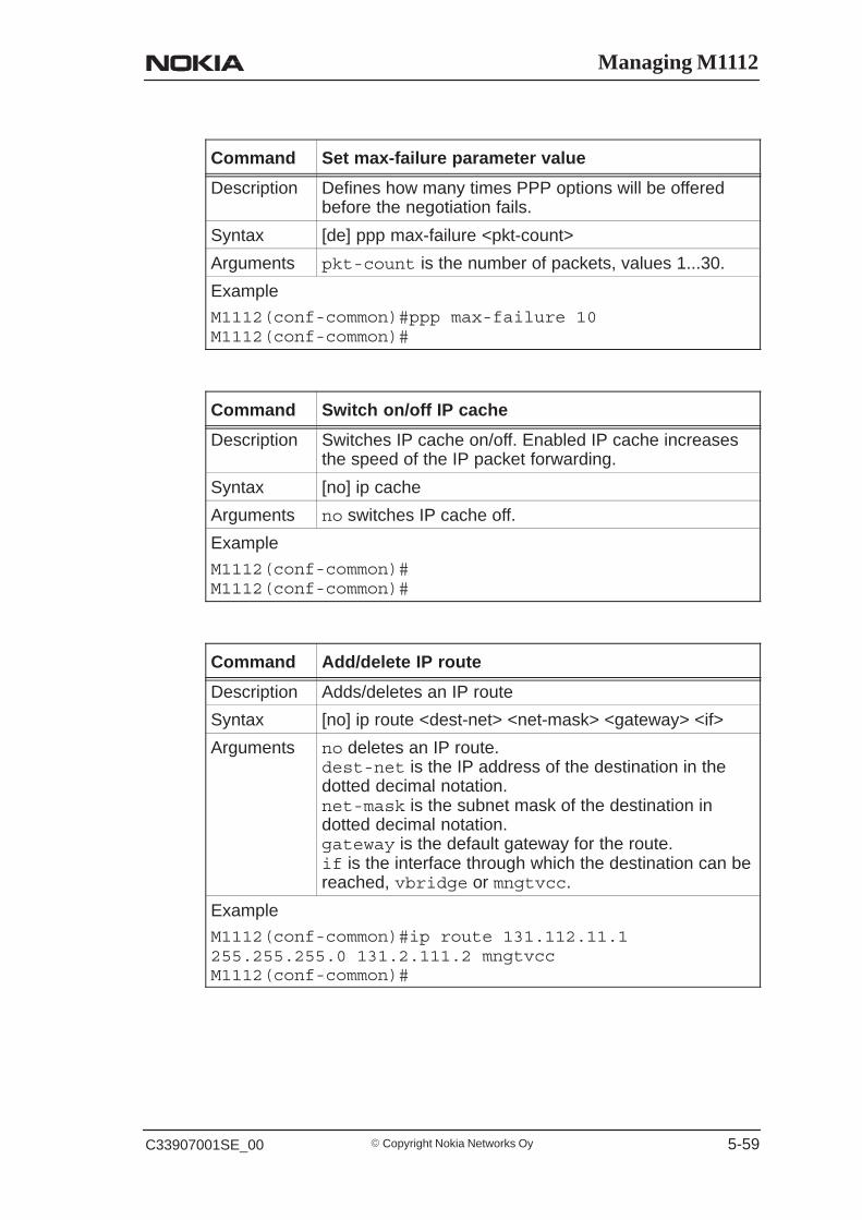
Managing M1112
� Copyright Nokia Networks OyC33907001SE_00 5-59
Command Set max-failure parameter value
Description Defines how many times PPP options will be offeredbefore the negotiation fails.
Syntax [de] ppp max-failure <pkt-count>
Arguments pkt-count is the number of packets, values 1...30.
Example
M1112(conf-common)#ppp max-failure 10M1112(conf-common)#
Command Switch on/off IP cache
Description Switches IP cache on/off. Enabled IP cache increasesthe speed of the IP packet forwarding.
Syntax [no] ip cache
Arguments no switches IP cache off.
Example
M1112(conf-common)#M1112(conf-common)#
Command Add/delete IP route
Description Adds/deletes an IP route
Syntax [no] ip route <dest-net> <net-mask> <gateway> <if>
Arguments no deletes an IP route.dest-net is the IP address of the destination in thedotted decimal notation.net-mask is the subnet mask of the destination indotted decimal notation.gateway is the default gateway for the route.if is the interface through which the destination can bereached, vbridge or mngtvcc.
Example
M1112(conf-common)#ip route 131.112.11.1255.255.255.0 131.2.111.2 mngtvccM1112(conf-common)#
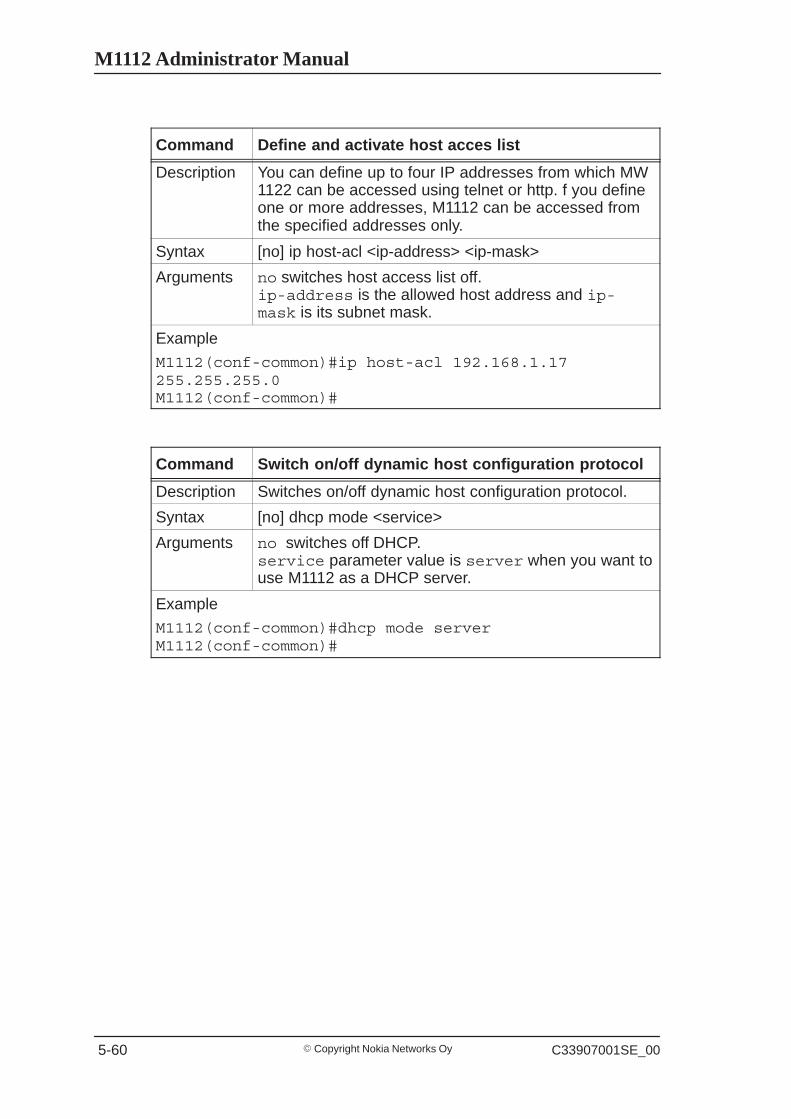
M1112 Administrator Manual
� Copyright Nokia Networks Oy C33907001SE_00 5-60
Command Define and activate host acces list
Description You can define up to four IP addresses from which MW1122 can be accessed using telnet or http. f you defineone or more addresses, M1112 can be accessed fromthe specified addresses only.
Syntax [no] ip host-acl <ip-address> <ip-mask>
Arguments no switches host access list off.ip-address is the allowed host address and ip-mask is its subnet mask.
Example
M1112(conf-common)#ip host-acl 192.168.1.17255.255.255.0M1112(conf-common)#
Command Switch on/off dynamic host configuration protocol
Description Switches on/off dynamic host configuration protocol.
Syntax [no] dhcp mode <service>
Arguments no switches off DHCP.service parameter value is server when you want touse M1112 as a DHCP server.
Example
M1112(conf-common)#dhcp mode serverM1112(conf-common)#
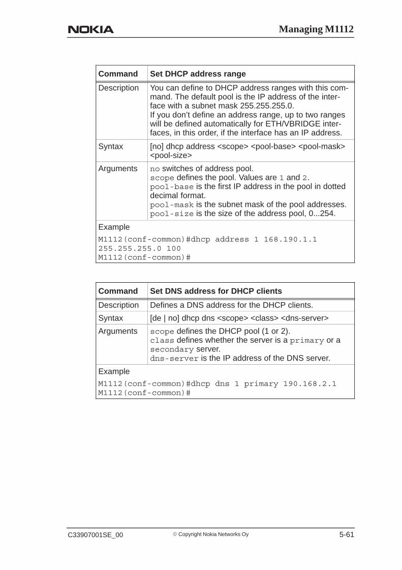
Managing M1112
� Copyright Nokia Networks OyC33907001SE_00 5-61
Command Set DHCP address range
Description You can define to DHCP address ranges with this com-mand. The default pool is the IP address of the inter-face with a subnet mask 255.255.255.0.If you don’t define an address range, up to two rangeswill be defined automatically for ETH/VBRIDGE inter-faces, in this order, if the interface has an IP address.
Syntax [no] dhcp address <scope> <pool-base> <pool-mask><pool-size>
Arguments no switches of address pool.scope defines the pool. Values are 1 and 2.pool-base is the first IP address in the pool in dotteddecimal format.pool-mask is the subnet mask of the pool addresses.pool-size is the size of the address pool, 0...254.
Example
M1112(conf-common)#dhcp address 1 168.190.1.1255.255.255.0 100M1112(conf-common)#
Command Set DNS address for DHCP clients
Description Defines a DNS address for the DHCP clients.
Syntax [de | no] dhcp dns <scope> <class> <dns-server>
Arguments scope defines the DHCP pool (1 or 2).class defines whether the server is a primary or asecondary server.dns-server is the IP address of the DNS server.
Example
M1112(conf-common)#dhcp dns 1 primary 190.168.2.1M1112(conf-common)#

M1112 Administrator Manual
� Copyright Nokia Networks Oy C33907001SE_00 5-62
Command Set DHCP server lease time
Description Defines the time how often the PC has to renew itsDHCP lease.
Syntax [de | no] dhcp lease-time <scope> <time-count>
Arguments scope defines the DHCP pool (1 or 2).time-count is the renewal interval in minutes,1...65535.
Example
M1112(conf-common)#dhcp lease-time 1 360M1112(conf-common)#
Command Set DHCP pool domain name
Description Set the domain name for the DHCP pool. The domainname is used to show the client in which network theclient is in.
Syntax [no] dhcp domain-name <scope> <name-string>
Arguments scope defines the DHCP pool (1 or 2).name-string set the domain name.
Example
M1112(conf-common)#dhcp domain-name 1 nokia M1112(conf-common)#
Command Set Domain name server address
Description Defines the address of the domain name server usedby M1112.
Syntax [no] dns <class> <dns-server>
Arguments no deletes domain name server address.class defines whether the server is a primary or asecondary name server.dns-server is the IP address of the DNS server.
Example
M1112(conf-common)#dns primary 190.168.12.1M1112(conf-common)#
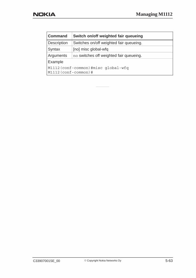
Managing M1112
� Copyright Nokia Networks OyC33907001SE_00 5-63
Command Switch on/off weighted fair queueing
Description Switches on/off weighted fair queueing.
Syntax [no] misc global-wfq
Arguments no switches off weighted fair queueing.
Example
M1112(conf-common)#misc global-wfqM1112(conf-common)#

M1112 Administrator Manual
� Copyright Nokia Networks Oy C33907001SE_00 5-64
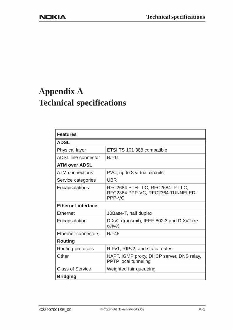
Technical specifications
� Copyright Nokia Networks OyC33907001SE_00 A-1
Appendix ATechnical specifications
Features
ADSL
Physical layer ETSI TS 101 388 compatible
ADSL line connector RJ-11
ATM over ADSL
ATM connections PVC, up to 8 virtual circuits
Service categories UBR
Encapsulations RFC2684 ETH-LLC, RFC2684 IP-LLC,RFC2364 PPP-VC, RFC2364 TUNNELED-PPP-VC
Ethernet interface
Ethernet 10Base-T, half duplex
Encapsulation DIXv2 (transmit), IEEE 802.3 and DIXv2 (re-ceive)
Ethernet connectors RJ-45
Routing
Routing protocols RIPv1, RIPv2, and static routes
Other NAPT, IGMP proxy, DHCP server, DNS relay,PPTP local tunneling
Class of Service Weighted fair queueing
Bridging

M1112 Administrator Manual
� Copyright Nokia Networks Oy C33907001SE_00 A-2
Features
Bridging Self-learning bridge, bridges between all inter-faces. Possibility to disable bridging betweenWAN interfaces.
MAC table 1024 entries
Class of Service Weighted fair queueing
Command line interface (CLI) for local management
Physical layer Electrically RS-232, TxD, RxD and GND sig-nals
Data format Asynchronous, 8+no parity
Bit rate 9600 bps
Flow control None
CLI connector RJ-45
Dedicated ATM management channel
Service categories UBR
Encapsulations RFC2684 ETH-LLC, RFC2684 IP-LLC,RFC2364 PPP-VC
IP addressing Statically configuredThrough IPCP when PPP over ATM is used
Routing Static routesRIPv1, RIPv2
Management proto-cols
Telnet/TCP/IP for command line interface,TFTP/UDP/IP for software and configurationdownload, HTTP/web server
Management through payload
Management proto-cols
Telnet/TCP/IP for command line interface,TFTP/UDP/IP for software and configurationdownload, HTTP/web server
Indicator lights
DSL ADSL line status
ETH-1, ETH-2,ETH-3, ETH-4
Ethernet activity and status
COL Ethernet collision
STA M1112 startup error
PWR Power on
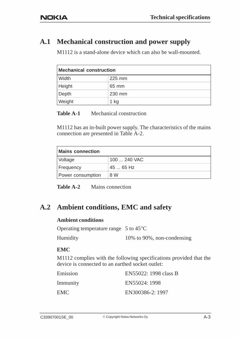
Technical specifications
� Copyright Nokia Networks OyC33907001SE_00 A-3
A.1 Mechanical construction and power supplyM1112 is a stand-alone device which can also be wall-mounted.
Mechanical construction
Width 225 mm
Height 65 mm
Depth 230 mm
Weight 1 kg
Table A-1 Mechanical construction
M1112 has an in-built power supply. The characteristics of the mainsconnection are presented in Table A-2.
Mains connection
Voltage 100 ... 240 VAC
Frequency 45 ... 65 Hz
Power consumption 8 W
Table A-2 Mains connection
A.2 Ambient conditions, EMC and safety
Ambient conditions
Operating temperature range 5 to 45°C
Humidity 10% to 90%, non-condensing
EMC
M1112 complies with the following specifications provided that thedevice is connected to an earthed socket outlet:
Emission EN55022: 1998 class B
Immunity EN55024: 1998
EMC EN300386-2: 1997

M1112 Administrator Manual
� Copyright Nokia Networks Oy C33907001SE_00 A-4
Overvoltage ITU-T K.21
Safety
Safety EN60950

Glossary
� Copyright Nokia Networks OyC33907001SE_00 Glossary-1
Glossary
Abbreviations
ADSL Asymmetric digital subscriber line
ATM Asynchronous transfer mode
CLI Command line interface
COL Collision
DMT Discrete multitone
DSL Digital subscriber line
DSLAM Digital Subscriber Line Access Multiplexer
EMC Electromagnetic compatibility
ETH Ethernet
IP Internet protocol
ISDN Intergrated services digital network
ISP Internet service provider
L2TP Layer 2 tunneling protocol
LAN Local area network
LLC Logical link control
MAC Media access control
PC Personal computer
POTS Plain old telephone system
PPP Point-to-point protocol

M1112 Administrator Manual
� Copyright Nokia Networks Oy C33907001SE_00Glossary-2
PPTP Point-to-point tunneling protocol
PWR Power
RAN Remote access node
RFC Request for comments
STA Status
TCP Transmission control protocol
UBR Unspecified bit rate
VCC Virtual channel connection
VCI Virtual channel identifier
VPI Virtual path identifier
WWW World Wide Web
Terms
10Base-T
10 Mbit/s Ethernet specification using two pairs of twisted cabling.10Base-T is a part of the IEEE 802.3 specification.
ATM access network
An access network where traffic from the subscribers is multiplexedand forwarded using ATM technology.
bridge
A device that connects two or more physical networks and forwardspackets between them. Bridges can usually be made to filter packets,that is, to forward only certain traffic.
command line interface
Character-based man-machine interface where a command line end-ing with <CR> character is used to configure a device. The device in-terprets the command and returns a character-based response.
Glossary
� Copyright Nokia Networks OyC33907001SE_00 Glossary-3
Digital Subscriber Line Access Multiplexer
A network element which multiplexes the traffic coming from thehigh-speed subscriber lines and forwards this traffic to the ATM net-work.
encapsulation
Wrapping of data in a protocol header.
Ethernet
LAN specification IEEE 802.3.
host
Computer system on a network.
Integrated services digital network
Integrated services network that provides digital connections betweenuser-network interfaces. ISDN provides or supports a range of differ-ent telecommunications services, for example a variety of telephonyand data services.
IP network
Data communications network based on the Internet Protocol.
ISDN filter
A device used for separating the ISDN signal from ADSL data signalsin the digital subscriber line.
MAC address
Ethernet address.

M1112 Administrator Manual
� Copyright Nokia Networks Oy C33907001SE_00Glossary-4
multiplexer
A device where several logical connections are combined into onephysical connection.
remote access node
RAN accepts a high concentration of data traffic from many DSLAMs.It grooms the traffic to reduce the heavy processing load for backbonerouters which can limit the scalability of high-speed networks. RANreceives cell- or frame-based end user traffic from the DSLAM andsends the aggregated IP traffic to ISP backbone routers.
serial console connection
Serial connection (CLI) on the back panel of M5122. It is used forconfiguring M5122 locally.
telecommuter
A person who works at home with data communications to the centraloffice.
virtual channel
A communications channel which provides for the sequential uni-directional transport of ATM cells.
virtual channel connection
A concatenation of virtual channel links that extends between thepoints where the ATM service users access the ATM layer.
virtual path
A unidirectional logical association of virtual channels.

Glossary
� Copyright Nokia Networks OyC33907001SE_00 Glossary-5
web browser
A software that is used to browse the World Wide Web.

M1112 Administrator Manual
� Copyright Nokia Networks Oy C33907001SE_00Glossary-6