Manual Del ABB 53SL6000
138
INSTRUCTION MANUAL Control IT Single Loop Controller 53SL6000 53SL6000 CONTROLLER PN24991
Transcript of Manual Del ABB 53SL6000

INSTRUCTION MANUALControlITSingle Loop Controller53SL6000
53SL6000 CONTROLLER
PN24991
The following are trademarks of ABB Automation Inc:EasyTuneMicro-DCI
WARNING notices as used in this manual apply to hazards or unsafe practices which could result in personal in-jury or death.
CAUTION notices apply to hazards or unsafe practices which could result in property damage.
NOTES highlight procedures and contain information which assist the operator in understanding the informationcontained in this manual.
All software, including design, appearance, algorithms and source codes, is owned and copyrighted byABB Automation Inc. or its suppliers.
WARNINGINSTRUCTION MANUALSDo not install, maintain or operate this equipment without reading, understanding and following theproper ABB Automation instructions and manuals, otherwise injury or damage may result.
POSSIBLE PROCESS UPSETSMaintenance must be performed only by qualified personnel and only after securing equipmentcontrolled by this product. Adjusting or removing this product while it is in the system may upset theprocess being controlled. Some process upsets may cause injury or damage.
NOTICE
The information contained in this document is subject to change without notice. ABB Automation Inc.reserves the right to make minor changes to this publication, such as company name & logos as well asother minor corrections, without necessarily changing the publication number.
ABB Automation Inc., its affiliates, employees, and agents, and the authors of and contributors to thispublication specifically disclaim all liabilities and warranties, express and implied (including warrantiesof merchantability and fitness for a particular purpose), for the accuracy, currency, completeness, and/orreliability of the information contained herein and/or for the fitness for any particular use and/or for theperformance of any material and/or equipment selected in whole or part with the user of/or in relianceupon information contained herein. Selection of materials and/or equipment is at the sole risk of theuser of this publication.
This document contains proprietary information of ABB Automation Inc. and is issued in strictconfidence. Its use, or reproduction for use, for the reverse engineering, development or manufacture ofhardware or software described herein is prohibited. No part of this document may be photocopied orreproduced without the prior written consent of ABB Automation Inc.
Copyright 2001 ABB Automation Inc. [April 2001]
Table of Contents
Safety Summary I
Read First II
1.0 Introduction 1-1
1.1 53SL6000 Controller Overview . . . . . . . . . . . . . . . . . . . . . . . . . 1-11.2 Controller Model Numbers . . . . . . . . . . . . . . . . . . . . . . . . . . . 1-31.3 Product Specifications . . . . . . . . . . . . . . . . . . . . . . . . . . . . . 1-3
2.0 Installation and Power-Up Procedures 2-1
2.1 Inspection . . . . . . . . . . . . . . . . . . . . . . . . . . . . . . . . . 2-12.2 Site Location . . . . . . . . . . . . . . . . . . . . . . . . . . . . . . . . . 2-12.3 Panel Mounting . . . . . . . . . . . . . . . . . . . . . . . . . . . . . . . . 2-1
2.3.1 Single Cutout Installation (NEMA4 Compliant) . . . . . . . . . . . . . . . 2-12.3.2 Multiple Cutout Installation . . . . . . . . . . . . . . . . . . . . . . . 2-1
2.4 Power Connections . . . . . . . . . . . . . . . . . . . . . . . . . . . . . . 2-12.4.1 24 V DC Power Connections . . . . . . . . . . . . . . . . . . . . . . 2-32.4.2 AC Power Connections . . . . . . . . . . . . . . . . . . . . . . . . . 2-3
2.5 Signal Connections . . . . . . . . . . . . . . . . . . . . . . . . . . . . . . 2-32.5.1 Analog Inputs AI1 and AI2 . . . . . . . . . . . . . . . . . . . . . . . 2-42.5.2 Discrete Outputs DO1 and DO2 . . . . . . . . . . . . . . . . . . . . . 2-42.5.3 Discrete Inputs DI1 and DI2 . . . . . . . . . . . . . . . . . . . . . . . 2-42.5.4 Analog Output AO1 . . . . . . . . . . . . . . . . . . . . . . . . . . 2-4
2.6 Universal Analog Input Module . . . . . . . . . . . . . . . . . . . . . . . . . 2-52.6.1 Universal Analog Input Module Backplane Installation . . . . . . . . . . . . 2-52.6.2 Universal Analog Input Module Signal Wiring . . . . . . . . . . . . . . . 2-5
2.6.2.1 Thermocouple Connections and Burn-out Detection . . . . . . . . . 2-52.7 2DI/2DO Module . . . . . . . . . . . . . . . . . . . . . . . . . . . . . . . 2-6
2.7.1 2DI/2DO Backplane Installation . . . . . . . . . . . . . . . . . . . . . 2-62.7.2 2DI/2DO Signal Wiring . . . . . . . . . . . . . . . . . . . . . . . . . 2-6
2.8 RS-232 and RS-485 Modules . . . . . . . . . . . . . . . . . . . . . . . . . . 2-72.8.1 RS-232 Plug Connections . . . . . . . . . . . . . . . . . . . . . . . 2-72.8.2 RS-485 Plug Connections . . . . . . . . . . . . . . . . . . . . . . . 2-7
2.9 Applying Power . . . . . . . . . . . . . . . . . . . . . . . . . . . . . . . . 2-72.9.1 Power-up Sequence . . . . . . . . . . . . . . . . . . . . . . . . . . 2-8
3.0 Display Panel 3-1
3.1 Display Panel Overview . . . . . . . . . . . . . . . . . . . . . . . . . . . . 3-13.2 Operator Mode . . . . . . . . . . . . . . . . . . . . . . . . . . . . . . . . 3-13.2.1 Operator Mode Panel Functions . . . . . . . . . . . . . . . . . . . . . . . . 3-13.3 Auxiliary Operator Access . . . . . . . . . . . . . . . . . . . . . . . . . . . 3-4
3.4 Operator Mode Overflow/ Underflow Indication . . . . . . . . . . . . . . . 3-4
Table of Contents 53SL6000 Instruction Manual
i

3.5 Engineer Mode . . . . . . . . . . . . . . . . . . . . . . . . . . . . . . . 3-53.5.1 Engineer Mode Display Panel . . . . . . . . . . . . . . . . . . . . . 3-53.5.2 Engineer Mode Hierarchical Structure . . . . . . . . . . . . . . . . . . 3-5
3.5.2.1 Editing a Parameter . . . . . . . . . . . . . . . . . . . . . 3-53.5.2.2 Deselecting and Scrolling Backward . . . . . . . . . . . . . . 3-63.5.2.3 Editing a Numeric Value . . . . . . . . . . . . . . . . . . . 3-63.5.2.4 Editing the Tag Parameter . . . . . . . . . . . . . . . . . . 3-7
3.6 Entering a Pass-Key . . . . . . . . . . . . . . . . . . . . . . . . . . . . . 3-83.6.1 Configuring a Pass-Key . . . . . . . . . . . . . . . . . . . . . . . . 3-8
3.7 Offline Display Pattern . . . . . . . . . . . . . . . . . . . . . . . . . . . . 3-83.8 Engineer Mode oPEr Selections . . . . . . . . . . . . . . . . . . . . . . . . 3-93.9 Display Alphanumerics . . . . . . . . . . . . . . . . . . . . . . . . . . . . 3-113.10 Engineer Mode Summary . . . . . . . . . . . . . . . . . . . . . . . . . . 3-11
4.0 Functional Overview 4-1
4.1 Simplified Block Diagram . . . . . . . . . . . . . . . . . . . . . . . . . . . 4-14.2 Detailed Block Diagram . . . . . . . . . . . . . . . . . . . . . . . . . . . . 4-2
5.0 Inputs/Outputs (I/O) 5-1
5.1 I/O Overview . . . . . . . . . . . . . . . . . . . . . . . . . . . . . . . . 5-15.2 Analog Inputs . . . . . . . . . . . . . . . . . . . . . . . . . . . . . . . . 5-15.3 Universal Analog Input Module . . . . . . . . . . . . . . . . . . . . . . . . . 5-2
5.3.1 Universal Analog Input Module Parameter Entries . . . . . . . . . . . . . 5-25.4 Analog Output 1 (AO1) . . . . . . . . . . . . . . . . . . . . . . . . . . . . 5-45.5 Discrete Inputs . . . . . . . . . . . . . . . . . . . . . . . . . . . . . . . 5-55.6 Discrete Outputs . . . . . . . . . . . . . . . . . . . . . . . . . . . . . . . 5-55.7 RS-232 and RS-485 Options . . . . . . . . . . . . . . . . . . . . . . . . . . 5-6
6.0 Signal Value Modification 6-1
6.1 Section Overview . . . . . . . . . . . . . . . . . . . . . . . . . . . . . . 6-16.2 Characterizer . . . . . . . . . . . . . . . . . . . . . . . . . . . . . . . . 6-1
6.2.1. 3SEG Mode . . . . . . . . . . . . . . . . . . . . . . . . . . . . 6-26.2.2 LSEG Mode . . . . . . . . . . . . . . . . . . . . . . . . . . . . . 6-26.2.3 PrGM Mode . . . . . . . . . . . . . . . . . . . . . . . . . . . . . 6-36.2.4 DtoA Mode . . . . . . . . . . . . . . . . . . . . . . . . . . . . . 6-4
6.3 Math Function Block . . . . . . . . . . . . . . . . . . . . . . . . . . . . . 6-46.3.1 ALG Mode . . . . . . . . . . . . . . . . . . . . . . . . . . . . . 6-56.3.2 SuMM Mode . . . . . . . . . . . . . . . . . . . . . . . . . . . . 6-56.3.3 PoLY Mode . . . . . . . . . . . . . . . . . . . . . . . . . . . . . 6-66.3.4 PoWr Mode . . . . . . . . . . . . . . . . . . . . . . . . . . . . . 6-66.3.5 LoG Mode . . . . . . . . . . . . . . . . . . . . . . . . . . . . . 6-66.3.6 LiM Mode . . . . . . . . . . . . . . . . . . . . . . . . . . . . . 6-66.3.7 SEL Mode . . . . . . . . . . . . . . . . . . . . . . . . . . . . . 6-76.3.8 Gas Flow Compensation Equations . . . . . . . . . . . . . . . . . . . 6-7
6.3.8.1 Linear Gas Flow Compensation (LFLo) Equation . . . . . . . . . 6-76.3.8.2 Square Root Gas Flow Compensation (SFLo) Equation . . . . . . 6-7
6.4 Logic Blocks 1, 2, 3, and 4 . . . . . . . . . . . . . . . . . . . . . . . . . . 6-7
53SL6000 Instruction Manual Table of Contents
ii

7.0 Control Scheme Block 7-1
7.1 Control Scheme Block . . . . . . . . . . . . . . . . . . . . . . . . . . . . . 7-17.2 Control Scheme Inputs . . . . . . . . . . . . . . . . . . . . . . . . . . . . . 7-17.3 Control Scheme Control Signals . . . . . . . . . . . . . . . . . . . . . . . . . 7-17.4 Signal Paths for the SnGL, cASc, L.LiM, and h.LiM Control Schemes . . . . . . . . . 7-6
7.4.1 Setpoint (SP-PV) Paths for the SnGL, cASc, L.LiM, and h.LiM Control . . . . . 7-67.4.2 PID Paths for the SnGL, cASc, L.LiM, and h.LiM Control Schemes . . . . . . 7-67.4.3 OUT Paths for the SnGL, cASc, L.LiM, and h.LiM Control Schemes . . . . . . 7-6
7.5 Signal Paths for the in.Ld Control Scheme . . . . . . . . . . . . . . . . . . . . . 7-77.6 Control Scheme Parameters . . . . . . . . . . . . . . . . . . . . . . . . . 7-247.7 Control Loop Parameters . . . . . . . . . . . . . . . . . . . . . . . . . . . 7-257.8 Control Scheme Signal Connector Pin Assignments . . . . . . . . . . . . . . . . 7-28
8.0 Eight Control Strategies 8-1
8.1 Single Loop Control with Remote Setpoint . . . . . . . . . . . . . . . . . . . . 8-18.1.1 AI1 - Process Variable Input . . . . . . . . . . . . . . . . . . . . . . 8-28.1.2 AI2 - Remote Setpoint Input . . . . . . . . . . . . . . . . . . . . . . . 8-28.1.3 DO1 - PV High Alarm Contact Out . . . . . . . . . . . . . . . . . . . . 8-28.1.4 DO2 - PV Low Alarm Contact Out . . . . . . . . . . . . . . . . . . . . 8-28.1.5 DI1 - Force Control Output Contact Input . . . . . . . . . . . . . . . . . 8-28.1.6 DI2 - Remote Enable Contact Input . . . . . . . . . . . . . . . . . . . 8-28.1.7 AO1 - Control Output . . . . . . . . . . . . . . . . . . . . . . . . . 8-28.1.8 SchM Selection . . . . . . . . . . . . . . . . . . . . . . . . . . . . 8-2
8.2 Analog Back-Up Control . . . . . . . . . . . . . . . . . . . . . . . . . . . . 8-38.2.1 AI1 - Process Variable Input . . . . . . . . . . . . . . . . . . . . . . 8-48.2.2 AI2 - Control Element Feedback . . . . . . . . . . . . . . . . . . . . . 8-48.2.3 DO1 - Computer Output Diverter . . . . . . . . . . . . . . . . . . . . . 8-48.2.4 DO2 - Backup Output Diverter . . . . . . . . . . . . . . . . . . . . . . 8-48.2.5 DI1 - Computer Ready . . . . . . . . . . . . . . . . . . . . . . . . . 8-48.2.6 DI2 - Auto Enable . . . . . . . . . . . . . . . . . . . . . . . . . . . 8-48.2.7 A01 - Backup Control Output . . . . . . . . . . . . . . . . . . . . . . 8-48.2.8 SchM Selection and Path Connections . . . . . . . . . . . . . . . . . . 8-4
8.3 Ratio Control . . . . . . . . . . . . . . . . . . . . . . . . . . . . . . . . . 8-58.3.1 AI1 - Controlled Variable Input . . . . . . . . . . . . . . . . . . . . . 8-58.3.2 AI2 - Wild Variable Input . . . . . . . . . . . . . . . . . . . . . . . . 8-58.3.3 DO1 - Controlled Variable High Alarm Contact Out . . . . . . . . . . . . . 8-58.3.4 DO2 - Controlled Variable Low Alarm Contact Out . . . . . . . . . . . . . 8-58.3.5 DI1 - Force Control Output Contact Input . . . . . . . . . . . . . . . . . 8-68.3.6 DI2 - Ratio Enable Contact Input . . . . . . . . . . . . . . . . . . . . . 8-68.3.7 Control Output . . . . . . . . . . . . . . . . . . . . . . . . . . . . 8-68.3.8 SPM = K-SP . . . . . . . . . . . . . . . . . . . . . . . . . . . . . 8-68.3.9 SchM Selection . . . . . . . . . . . . . . . . . . . . . . . . . . . . 8-6
8.4 Auto/Manual Selector . . . . . . . . . . . . . . . . . . . . . . . . . . . . . 8-78.4.1 AI1 - Process Variable 1 Input . . . . . . . . . . . . . . . . . . . . . . 8-78.4.2 AI2 - Process Variable 2 Input (Auto) . . . . . . . . . . . . . . . . . . . 8-78.4.3 DO1 - PV1 High Alarm Contact Out . . . . . . . . . . . . . . . . . . . 8-78.4.4 D02 - PV1 Low Alarm Contact Out . . . . . . . . . . . . . . . . . . . . 8-88.4.5 DI1 Force Output Contact Input . . . . . . . . . . . . . . . . . . . . . 8-88.4.7 A01 - PV2 Re-Transmit (Auto) . . . . . . . . . . . . . . . . . . . . . . 8-88.4.8 SchM Selection . . . . . . . . . . . . . . . . . . . . . . . . . . . . 8-8
Table of Contents 53SL6000 Instruction Manual
iii
8.5 Single Station Cascade Control . . . . . . . . . . . . . . . . . . . . . . . . 8-98.5.1 AI1 - Secondary PV Input . . . . . . . . . . . . . . . . . . . . . . . 8-98.5.2 AI2 - Primary PV Input . . . . . . . . . . . . . . . . . . . . . . . . 8-98.5.3 DO1 - Secondary PV High Alarm Contact Out . . . . . . . . . . . . . . 8-98.5.4 DO2 - Secondary PV Low Alarm Contact Out . . . . . . . . . . . . . . 8-108.5.5 DI1 - Force Control Output Contact Input . . . . . . . . . . . . . . . . 8-108.5.6 DI2 - Cascade Enable Contact Input . . . . . . . . . . . . . . . . . . 8-108.5.7 Primary Output (the Setpoint into the Secondary Loop) . . . . . . . . . . . 8-108.5.8 AO1 - Control Output . . . . . . . . . . . . . . . . . . . . . . . . . 8-108.5.9 SchM Selection . . . . . . . . . . . . . . . . . . . . . . . . . . . 8-10
8.6 Single Station Override Control . . . . . . . . . . . . . . . . . . . . . . . . 8-118.6.1 AI1 - Primary PV Input . . . . . . . . . . . . . . . . . . . . . . . . 8-118.6.2 AI2 - Limiting PV Input . . . . . . . . . . . . . . . . . . . . . . . . 8-118.6.3 DO1 - Primary PV High AlarmContact Out . . . . . . . . . . . . . . . . 8-118.6.4 DO2 - Primary PV Low Alarm Contact Out . . . . . . . . . . . . . . . . 8-128.6.5 DI1 - Force Control Output Contact Input . . . . . . . . . . . . . . . . 8-128.6.6 DI2 - Secondary Setpoint Enable . . . . . . . . . . . . . . . . . . . . 8-128.6.7 AO1 - Control Output . . . . . . . . . . . . . . . . . . . . . . . . . 8-128.6.8 SchM Selection . . . . . . . . . . . . . . . . . . . . . . . . . . . 8-12
8.7 Dual Indicator with Re-Transmitted PV . . . . . . . . . . . . . . . . . . . . . 8-138.7.1 AI1 - PV1 Input . . . . . . . . . . . . . . . . . . . . . . . . . . . 8-138.7.2 AI2 - PV2 Input . . . . . . . . . . . . . . . . . . . . . . . . . . . 8-138.7.3 DO1 - PV1 High Alarm Contact Out . . . . . . . . . . . . . . . . . . . 8-138.7.4 DO2 - PV1 Low Alarm Contact Out . . . . . . . . . . . . . . . . . . . 8-138.7.5 A01 - Retransmitted PV1 or PV2 . . . . . . . . . . . . . . . . . . . . 8-138.7.6 SchM Selection . . . . . . . . . . . . . . . . . . . . . . . . . . . 8-13
8.8 Proportional Speed Floating Control . . . . . . . . . . . . . . . . . . . . . . 8-148.8.1 Motorized Valve Connections . . . . . . . . . . . . . . . . . . . . . 8-148.8.2 Configuration Requirements . . . . . . . . . . . . . . . . . . . . . . 8-148.8.3 Speed Factor Adjusting . . . . . . . . . . . . . . . . . . . . . . . . 8-15
9.0 Commissioning 9-1
9.1 Overview . . . . . . . . . . . . . . . . . . . . . . . . . . . . . . . . . . 9-19.2 Proportional Action (Pb) . . . . . . . . . . . . . . . . . . . . . . . . . . . . 9-19.3 Integral Action (tr) . . . . . . . . . . . . . . . . . . . . . . . . . . . . . . 9-19.4 Derivative Action (td) . . . . . . . . . . . . . . . . . . . . . . . . . . . . . 9-29.5 Trial and Error Tuning Method . . . . . . . . . . . . . . . . . . . . . . . . . 9-29.6 Proportional Cycle Tuning Method . . . . . . . . . . . . . . . . . . . . . . . 9-29.7 Step Response Tuning Method (Ziegler-Nichols) . . . . . . . . . . . . . . . . . 9-29.8 Easy-Tune . . . . . . . . . . . . . . . . . . . . . . . . . . . . . . . . 9-3
9.8.1 Executing Easy-Tune . . . . . . . . . . . . . . . . . . . . . . . . . 9-59.8.2 Easy-Tune Determined Values . . . . . . . . . . . . . . . . . . . . . 9-79.8.3 Easy-Tune Status Responses . . . . . . . . . . . . . . . . . . . . . 9-7
9.8.3.1 out Response . . . . . . . . . . . . . . . . . . . . . . . . 9-89.8.3.2 dout Response . . . . . . . . . . . . . . . . . . . . . . . 9-89.8.3.3 dPV Response . . . . . . . . . . . . . . . . . . . . . . . 9-89.8.3.4 outX Response . . . . . . . . . . . . . . . . . . . . . . . 9-89.8.3.5 StiM Response . . . . . . . . . . . . . . . . . . . . . . . 9-89.8.3.6 PtiM Response . . . . . . . . . . . . . . . . . . . . . . . 9-89.8.3.7 WtiM Response . . . . . . . . . . . . . . . . . . . . . . . 9-89.8.3.8 KtiM Response . . . . . . . . . . . . . . . . . . . . . . . 9-89.8.3.9 ttiM Response . . . . . . . . . . . . . . . . . . . . . . . 9-89.8.3.10 Abrt Response . . . . . . . . . . . . . . . . . . . . . . . 9-8
53SL6000 Instruction Manual Table of Contents
iv
9.8.3.11 PidL Response . . . . . . . . . . . . . . . . . . . . . . . 9-89.8.3.12 cM Response . . . . . . . . . . . . . . . . . . . . . . . . 9-89.8.3.13 cASc Response . . . . . . . . . . . . . . . . . . . . . . . 9-89.8.3.14 oVr Response . . . . . . . . . . . . . . . . . . . . . . . . 9-8
Appendix A: Glossary A-1
Appendix B: Maintenance and Parts List B-1
B.1 Overview . . . . . . . . . . . . . . . . . . . . . . . . . . . . . . . . . . B-1B.2 Parts List . . . . . . . . . . . . . . . . . . . . . . . . . . . . . . . . . . B-1B.3 Removal and Replacement . . . . . . . . . . . . . . . . . . . . . . . . . . . B-2B.4 Controller Confidence Test Procedure . . . . . . . . . . . . . . . . . . . . . . B-3
B.4.1 Jumper Connections for the Controller Confidence Test . . . . . . . . . . . B-3B.4.2 Starting the Controller Confidence Test via the Faceplate Push Buttons . . . . B-4B.4.3 Starting the Controller Confidence Test via Datalink . . . . . . . . . . . . B-4B.4.4 Controller Confidence Test Suite . . . . . . . . . . . . . . . . . . . . B-5B.4.5 Controller Confidence Test Status . . . . . . . . . . . . . . . . . . . . B-5B.4.6 Exiting the Controller Confidence Test via the Faceplate Push Buttons . . . . . B-5B.4.7 Exiting the Controller Confidence Test via Datalink . . . . . . . . . . . . . B-5
B.5 Defaulting the Database . . . . . . . . . . . . . . . . . . . . . . . . . . . . B-6B.6 Analog Input/Output Calibration Values . . . . . . . . . . . . . . . . . . . . . . B-6B.7 Watchdog LED . . . . . . . . . . . . . . . . . . . . . . . . . . . . . . . . B-6
Appendix C: Datalink Protocol C-1
C.1 Overview . . . . . . . . . . . . . . . . . . . . . . . . . . . . . . . . . . C-1C.2 Configuring the System Module for Datalink . . . . . . . . . . . . . . . . . . . . C-1C.3 Protocol . . . . . . . . . . . . . . . . . . . . . . . . . . . . . . . . . . . C-1
C.3.1 Message Types . . . . . . . . . . . . . . . . . . . . . . . . . . . . C-2C.3.2 Transaction Examples . . . . . . . . . . . . . . . . . . . . . . . . . C-2
C.4 Mnemonic-to-Datapoint Cross Reference . . . . . . . . . . . . . . . . . . . . . C-3C.4.1 Database Starting Addresses . . . . . . . . . . . . . . . . . . . . . . C-3C.4.2 Controller Memory Address Scheme . . . . . . . . . . . . . . . . . . . C-3C.4.3 Database Prompt-to-Datapoint Cross Reference . . . . . . . . . . . . . . C-5
C.5 Executing Controller Self Tests via Datalink . . . . . . . . . . . . . . . . . . . . C-8
Appendix D: Prompt List D-1
Photocopy-Ready Pocket Reference Guide Last Sheet
Table of Contents 53SL6000 Instruction Manual
v
List of TablesTable 1-1. 53SL6000 Model Numbers . . . . . . . . . . . . . . . . . . . . . . . . 1-3
Table 2-1. Controller Status Codes . . . . . . . . . . . . . . . . . . . . . . . . . 2-8
Table 3-1. Operator Mode Display Items . . . . . . . . . . . . . . . . . . . . . . 3-3Table 3-2. Setpoint Up/Down Push Buttons . . . . . . . . . . . . . . . . . . . . . 3-4Table 3-3. oPEr Menu Selections . . . . . . . . . . . . . . . . . . . . . . . . . 3-9Table 3-4. Operator Enable (oPr) Prompts . . . . . . . . . . . . . . . . . . . . . 3-11
Table 5-1. Analog Input Selections . . . . . . . . . . . . . . . . . . . . . . . . . 5-1Table 5-2. Analog Input Registers . . . . . . . . . . . . . . . . . . . . . . . . . 5-1Table 5-3. Input Type Prompts . . . . . . . . . . . . . . . . . . . . . . . . . . 5-2Table 5-4. Volt/Millivolt Input Types . . . . . . . . . . . . . . . . . . . . . . . . 5-3Table 5-5. Thermocouple Types . . . . . . . . . . . . . . . . . . . . . . . . . . 5-3Table 5-6. RTD Types . . . . . . . . . . . . . . . . . . . . . . . . . . . . . . 5-3Table 5-7. Frequency/Pulse Input Types . . . . . . . . . . . . . . . . . . . . . . 5-4Table 5-8. Calibration Constants . . . . . . . . . . . . . . . . . . . . . . . . . . 5-4Table 5-9. Analog Output Selections . . . . . . . . . . . . . . . . . . . . . . . . 5-4Table 5-10. Analog Output Registers . . . . . . . . . . . . . . . . . . . . . . . . 5-4Table 5-11. Discrete Input Selections . . . . . . . . . . . . . . . . . . . . . . . 5-5Table 5-12. Discrete Output Selections . . . . . . . . . . . . . . . . . . . . . . . 5-5Table 5-13. System (SYS) Prompts . . . . . . . . . . . . . . . . . . . . . . . . 5-6
Table 6-1. Characterizer Parameters . . . . . . . . . . . . . . . . . . . . . . . . 6-1Table 6-2. Math Function Block Parameters . . . . . . . . . . . . . . . . . . . . . 6-5Table 6-3. Logic Block Parameters . . . . . . . . . . . . . . . . . . . . . . . . . 6-8Table 6-4. Discrete Logic Block Functions . . . . . . . . . . . . . . . . . . . . . . 6-8
Table 7-1. Control Signal Descriptions . . . . . . . . . . . . . . . . . . . . . . . 7-3Table 7-2. Control Scheme Parameters . . . . . . . . . . . . . . . . . . . . . . . 7-24Table 7-3. Control Selections . . . . . . . . . . . . . . . . . . . . . . . . . . . 7-25
Table 9-1. ITAE Equations . . . . . . . . . . . . . . . . . . . . . . . . . . . . 9-3Table 9-2. Easy-Tune Parameters . . . . . . . . . . . . . . . . . . . . . . . . . 9-7Table 9-3. Easy-Tune Determined Values . . . . . . . . . . . . . . . . . . . . . . 9-7
Table B-1. Parts List . . . . . . . . . . . . . . . . . . . . . . . . . . . . . . . B-2Table B-2. Confidence Test Suite . . . . . . . . . . . . . . . . . . . . . . . . . B-5Table B-3. Factory Subtest Descriptions . . . . . . . . . . . . . . . . . . . . . . B-5
Table C-1. System (SYS) Prompts (Datalink) . . . . . . . . . . . . . . . . . . . . C-1Table C-2. Datalink Protocol . . . . . . . . . . . . . . . . . . . . . . . . . . . C-1Table C-3. Datapoint Types . . . . . . . . . . . . . . . . . . . . . . . . . . . . C-3Table C-4. Database Starting Addresses . . . . . . . . . . . . . . . . . . . . . . C-3Table C-5. Datapoint Addresses . . . . . . . . . . . . . . . . . . . . . . . . . . C-3Table C-6. Prompt-to-Datapoint Cross Reference . . . . . . . . . . . . . . . . . . . C-5
53SL6000 Instruction Manual Table of Contents
vi

List of FiguresFigure 1-1. 53SL6000 Controller . . . . . . . . . . . . . . . . . . . . . . . . . . . 1-2
Figure 2-1. Panel Cutout and Installation . . . . . . . . . . . . . . . . . . . . . . . 2-2Figure 2-2. Power Plug . . . . . . . . . . . . . . . . . . . . . . . . . . . . . . 2-3Figure 2-3. 24 V DC Power Connections . . . . . . . . . . . . . . . . . . . . . . . 2-3Figure 2-4. AC Power Connections . . . . . . . . . . . . . . . . . . . . . . . . . 2-3Figure 2-5. Signal Plug . . . . . . . . . . . . . . . . . . . . . . . . . . . . . . 2-4Figure 2-6. Signal Plug Connections . . . . . . . . . . . . . . . . . . . . . . . . . 2-4Figure 2-7. Universal Analog Input Module . . . . . . . . . . . . . . . . . . . . . . 2-5Figure 2-8. Input Configurations . . . . . . . . . . . . . . . . . . . . . . . . . . . 2-6Figure 2-9. 2DI/2DO Module . . . . . . . . . . . . . . . . . . . . . . . . . . . . 2-6Figure 2-10. 2DI Plug Connections . . . . . . . . . . . . . . . . . . . . . . . . . 2-6Figure 2-11. 2DO Plug Connections . . . . . . . . . . . . . . . . . . . . . . . . . 2-7Figure 2-12. RS-232 or RS-485 Module . . . . . . . . . . . . . . . . . . . . . . . 2-7Figure 2-13. RS-232 Plug Connections . . . . . . . . . . . . . . . . . . . . . . . . 2-7Figure 2-14. RS-485 Plug Connections . . . . . . . . . . . . . . . . . . . . . . . . 2-7
Figure 3-1. Display Panel Overview . . . . . . . . . . . . . . . . . . . . . . . . . 3-1Figure 3-3. Overflow/Underflow Indicators . . . . . . . . . . . . . . . . . . . . . . 3-4Figure 3-4. Engineer Mode Display Panel . . . . . . . . . . . . . . . . . . . . . . . 3-5Figure 3-5. Editing a Parameter . . . . . . . . . . . . . . . . . . . . . . . . . . . 3-6Figure 3-6. Deselecting and Scrolling Backward . . . . . . . . . . . . . . . . . . . . 3-7Figure 3-7. Editing a Red dro Value . . . . . . . . . . . . . . . . . . . . . . . . . 3-7Figure 3-8. Moving the Red dro Decimal Point . . . . . . . . . . . . . . . . . . . . . 3-7Figure 3-9. Editing a tAG . . . . . . . . . . . . . . . . . . . . . . . . . . . . . 3-8Figure 3-10. KEY? Prompt . . . . . . . . . . . . . . . . . . . . . . . . . . . . . 3-8Figure 3-11. Offline Display Pattern . . . . . . . . . . . . . . . . . . . . . . . . . 3-9Figure 3-12. Display Alphanumerics . . . . . . . . . . . . . . . . . . . . . . . . 3-11
Figure 4-1. Simplified Controller Block Diagram . . . . . . . . . . . . . . . . . . . . 4-1Figure 4-2. Detailed Functional Controller Block Diagram . . . . . . . . . . . . . . . . 4-5
Figure 7-1. Input Signal Designators by Control Scheme . . . . . . . . . . . . . . . . 7-2Figure 7-2. Control Signal Logic Paths . . . . . . . . . . . . . . . . . . . . . . . . 7-5Figure 7-3. SnGL, cASc, L.LiM, and h.LiM Signal Paths . . . . . . . . . . . . . . . . . 7-8Figure 7-4. Common Setpoint Logic Paths . . . . . . . . . . . . . . . . . . . . . . 7-9Figure 7-5. Local Standard (Std) Setpoint Path . . . . . . . . . . . . . . . . . . . . 7-9Figure 7-6. Remote Ratio Setpoint Path . . . . . . . . . . . . . . . . . . . . . . 7-10Figure 7-7. StV Setpoint Tracking . . . . . . . . . . . . . . . . . . . . . . . . . 7-10Figure 7-8. PVt Setpoint Tracking . . . . . . . . . . . . . . . . . . . . . . . . . 7-11Figure 7-9. cASc Control Scheme Setpoint Path . . . . . . . . . . . . . . . . . . . 7-12Figure 7-10. Pb, td, and tr PID Paths . . . . . . . . . . . . . . . . . . . . . . . . 7-13Figure 7-11. Pb, td, tr, and FF PID Paths . . . . . . . . . . . . . . . . . . . . . . 7-14Figure 7-12. Pb, td, tr, and FF PID Paths with EXrF . . . . . . . . . . . . . . . . . 7-15Figure 7-13. Output Tracking Path . . . . . . . . . . . . . . . . . . . . . . . . . 7-16Figure 7-14. Auto Output Path . . . . . . . . . . . . . . . . . . . . . . . . . . 7-17Figure 7-15. Manual Output Path . . . . . . . . . . . . . . . . . . . . . . . . . 7-18
Table of Contents 53SL6000 Instruction Manual
vii

Figure 7-16. Auto Digital Output Path . . . . . . . . . . . . . . . . . . . . . . . . 7-19Figure 7-17. in.Ld Control Scheme Alarmed Variable Input . . . . . . . . . . . . . . . 7-20Figure 7-18. in.Ld Control Scheme Auto Input with Digital Output . . . . . . . . . . . . 7-21Figure 7-19. in.Ld Control Scheme Output Tracking . . . . . . . . . . . . . . . . . . 7-22Figure 7-20. in.Ld Control Scheme Manual Operation . . . . . . . . . . . . . . . . . 7-23Figure 7-21. Control Schemes Signal Connector Pin Assignments . . . . . . . . . . . . 7-29
Figure 8-1. Single Loop Application . . . . . . . . . . . . . . . . . . . . . . . . 8-1Figure 8-2. Single Loop Signals . . . . . . . . . . . . . . . . . . . . . . . . . . 8-1Figure 8-3. Backup Control Application . . . . . . . . . . . . . . . . . . . . . . . 8-3Figure 8-4. Output Selector . . . . . . . . . . . . . . . . . . . . . . . . . . . . 8-3Figure 8-5. Backup Control Signals . . . . . . . . . . . . . . . . . . . . . . . . 8-3Figure 8-6. Ratio Control Application . . . . . . . . . . . . . . . . . . . . . . . . 8-5Figure 8-7. Ratio Control Signals . . . . . . . . . . . . . . . . . . . . . . . . . 8-5Figure 8-8. A/M Selector Application . . . . . . . . . . . . . . . . . . . . . . . . 8-7Figure 8-9. A/M Selector Signals . . . . . . . . . . . . . . . . . . . . . . . . . . 8-7Figure 8-10. Single Station Cascade Control Application . . . . . . . . . . . . . . . . 8-9Figure 8-11. Single Station Cascade Signals . . . . . . . . . . . . . . . . . . . . 8-9Figure 8-12. Single Station Override Control Application . . . . . . . . . . . . . . . . 8-11Figure 8-13. Single Station Override Control Signals . . . . . . . . . . . . . . . . . 8-11Figure 8-14. Dual Indicator Application . . . . . . . . . . . . . . . . . . . . . . . 8-13Figure 8-15. Dual Indicator Signals . . . . . . . . . . . . . . . . . . . . . . . . . 8-13Figure 8-16. Proportional Speed Floating Control . . . . . . . . . . . . . . . . . . . 8-14
Figure 9-1. Typical Step Response Record . . . . . . . . . . . . . . . . . . . . . 9-3Figure 9-2. Easy-Tune Process . . . . . . . . . . . . . . . . . . . . . . . . . . 9-4Figure 9-3. Preliminary Step Response - Actual Curve . . . . . . . . . . . . . . . . 9-4Figure 9-4. Preliminary Step Response - Approximated Curve . . . . . . . . . . . . . 9-4Figure 9-5. Easy-Tune Display . . . . . . . . . . . . . . . . . . . . . . . . . . . 9-6
Figure B-1. Illustrated Parts Breakdown . . . . . . . . . . . . . . . . . . . . . . . B-1Figure B-2. Bezel and Lever Tabs . . . . . . . . . . . . . . . . . . . . . . . . . B-3Figure B-3. Confidence Test Connections . . . . . . . . . . . . . . . . . . . . . . B-4Figure B-4. Watchdog LED . . . . . . . . . . . . . . . . . . . . . . . . . . . . B-6
Figure C-1. Floating Point Examples . . . . . . . . . . . . . . . . . . . . . . . . C-4
53SL6000 Instruction Manual Table of Contents
viii

GENERAL Electric Shock Hazard During MaintenanceWARNINGS Disconnect power or take precautions to ensure that contact with
energized parts is avoided when servicing.
Input Connector Shock HazardInstruments powered from an ac line source may cause input connec-tors to have power even though the controller is powered off.
Safety HazardSubstitution of or modification with improper replacement componentsmay impair the safety of this device.
GENERAL Equipment EnvironmentCAUTIONS All components, whether in transportation, operation or storage must
be in a noncorrosive environment.
Special HandlingThis unit uses electrostatic sensitive devices.
SPECIFIC Instruments that are powered from an ac line serviceWARNINGS constitute a potential electric shock hazard to the user; therefore, only
qualified technicians should install the unit. Make certain that the acpower lines are disconnected from the operating branch circuit beforeattempting electrical connections. (p. 2-1)
Always remove power before attempting to install, disassemble, orservice the controller. Failure to remove power may result in seriouspersonal injury and/or equipment damage. (p. B-2)
SPECIFIC Use a grounded wrist strap to prevent damage to integrated circuitCAUTIONS devices when handling circuit boards. (p. B-2)
Safety Summary
53SL6000 Instruction Manual I

Read First
WARNING
INSTRUCTION MANUALSDo not install, maintain, or operate this equipment without reading,
understanding and following the proper ABB Automation instructionsand manuals, otherwise injury or damage may result.
RETURN OF EQUIPMENTAll Flowmeters and/or Signal Converters being returned to ABB
Automation for repair must be free of any hazardous materials (acids,alkalis, solvents, etc). A Material Safety Data Sheet (MSDS) for all
process liquids must accompany returned equipment. Contact ABBAutomation for authorization prior to returning equipment.
Read these instructions before starting installation; save these instructions for future reference.
Contacting ABB Automation Inc.
Should assistance be required with any ABB Instrumentation product, contact the following:
Telephone:
ABB Instrumentation Technical Support Center1 (800) 697-9619
E-Mail:
II

1.1 53SL6000 Controller OverviewThe 53SL6000 controller is a functionally robustinstrument capable of performing any one of manycontrol strategies. Typical control strategies thatcan be readily implemented are:
• Single Loop Control with Remote Setpoint(PID control)
• Analog Back-up Control• Ratio Control (PID control)• Auto/Manual Selector• Single Station Cascade Control (Dual PID
control)• Single Station Override Control (Dual PID
control)• Dual Indicator with Re-Transmitted Proc-
ess Variable (PV)• Proportional Speed Floating Control (re-
quires the 2DI/2DO option module)
The complexity of learning software languages orsignal interconnection schemes is eliminated, as allparameter entries are prompt-driven to configurea control strategy. Mnemonic prompts appear onthe display panel to solicit the necessary re-sponses.
As listed below, a suite of control modifiers andsignal conditioners is provided to supplement everycontrol strategy.
Control Modifiers:• External Reset Feedback• Additive Feedforward• External/Internal (Safety) Output Tracking• Output High/Low/Rate-of-Change Limiting• Process Variable/Internal (Safety) Set-
point Tracking• Setpoint High/Low/Rate-of-Change
Limiting
Signal Conditioners:• Twelve Linear Segment Characterizer• Five Third Order Segment Characterizer• Third Order Polynomial• Flow Compensation• Exponentiation• Algebraic Component Combinations• Logarithmic Extraction• Contact Duration-to-Analog
• Summation• Setpoint Programmer
Every control strategy is also supported with astandard controller I/O complement that includestwo 0/4-20 mA inputs, two digital/contact inputs,one 0/4-20 mA output, and two contact outputs.
Also available for every control strategy is addi-tional functionality provided by optional I/O mod-ules that mount externally at the rear of thecontroller for easy upgrade. Available option mod-ules are as follows:
• RS-232 Communications Module - providespersonal computer communication port con-nectivity (can not coexist with the RS-485 mod-ule).
• RS-485 Communications Module - providesdatalink connectivity capabilities (can not co-exist with the RS-232 module).
• Universal Analog Input Module - provides oneor two isolated inputs that accept RTD, thermo-couple, millivolt, volt, and frequency inputs.The thermocouple and RTD inputs are auto-matically linearized.
• 2DI/2DO Module - provides two additional digi-tal inputs and two digital outputs. With thisoption, a time proportional or three-step outputcan be applied to the 2DO relays for propor-tional speed floating control.
Power dependent transmitters are provided operat-ing current from a 50 mA (24 V dc) transmitterpower supply located in the controller.
Tuning the 53SL6000 controller is automated withEasyTune, the ABB Automation algorithm de-signed to calculate the optimal PID values for pre-c i se ana log con t ro l r esponses to p rocessdeviations.
The 53SL6000 controller is easy to install due to itssmall size. Installation depth is only 2 7/8 inches(73 mm) without option modules and 4 21/32inches (118.1 mm) with option modules. A 1 inch(25.4 mm) access space is required for rear termi-nal plug removal and insertion.
An illustration of the 53SL6000 controller that de-picts the front display panel and the option modulesis provided in Figure 1-1.
1.0 Introduction
Section 1. Introduction 53SL6000 Instruction Manual
1-1
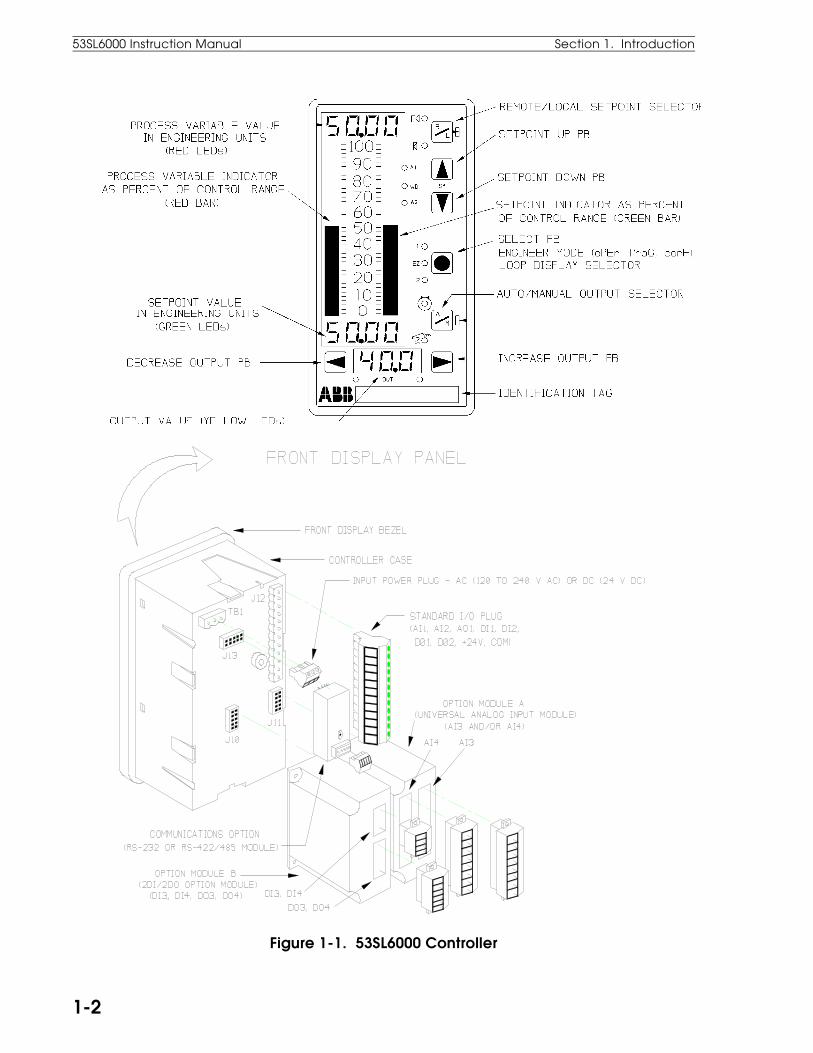
Figure 1-1. 53SL6000 Controller
53SL6000 Instruction Manual Section 1. Introduction
1-2

1.2 Controller Model NumbersThe 53SL6000 controller model numbers are de-scribed in Table 1-1.
Table 1-1. 53SL6000 Model Numbers53 SL6 ♦ ♦ ♦ A ♦ ♦
Controllers 53Design Designator(includes analog inputs1 and 2, analog output1, discrete inputs 1 and2, discrete outputs 1and 2)
SL6
Power Requirements:
120/240 V ac 0
24 V dc 1
Option Slot A Module:
None 0
Single Universal Analog Input(analog input 3)
1
Dual Universal Analog Input(analog inputs 3 and 4)
(Each universal analog input canaccept RTD, thermocouple,millivolt, voltage, andfrequency inputs. Thermo-couple inputs are linearizedby this module.)
2
Option Slot B Module:
None.
2 Discrete Input/2 DiscreteOutput (discrete inputs 3and 4, discrete outputs 3and 4)
0
3
Design Level A
Communications Mode:
None 0RS-485 (allows datalink connection) 1RS-232 (allows connection to apersonal computer or a modem)
2
Enclosure:
Standard Panel Mount Case 0
1.3 Product SpecificationsThe 53SL6000 controller conforms to the followingspecifications and complies with the following regu-latory requirements:
Physical CharacteristicsWeight < 1.5 kg (3 lb 5 oz)
Front Dimension 72 x 144 mm (2 53/64 x 5 43/64 in)
Overall Length With Option Modules - 130.8 mm(5.15 in)
Without Option Modules - 85.7mm (3 3/8 in)
Panel InstallationPanel Cutout See Figure 2-1
Installation Depth Allow an additional 25.4 mm (1inch) for rear plug removal andinsertion.
Mounting Position Flush panel mounting ± 60°
Degree of ProtectionFacial NEMA4 (IP64)
Housing NEMA1 (IP20)
Safety ClassificationCSA Approved for Class 1,
Division 2 (planned).
FM FM Approved for Class 1,Division 2 (planned)
Environmental LimitsOperating Ambient -5 to 50°C (23 to 122° F)Temperature Limits
Storage/Transport -40 to 85°C (-40 to 185° F)AmbientTemperature Limits
Relative Humidity LimitsHumidity Limits 5 to 95%(operation)
Humidity Limits 5 to 100%(storage/transport)
Barometric 82.7 to 103.4 kPaPressure(operation)
Barometric 13.8 to 103.4 kPaPressure(storage/transport)
Thermal Shock ± 20°C/hr ( ± 68° F /hr)(operation)
Section 1. Introduction 53SL6000 Instruction Manual
1-3
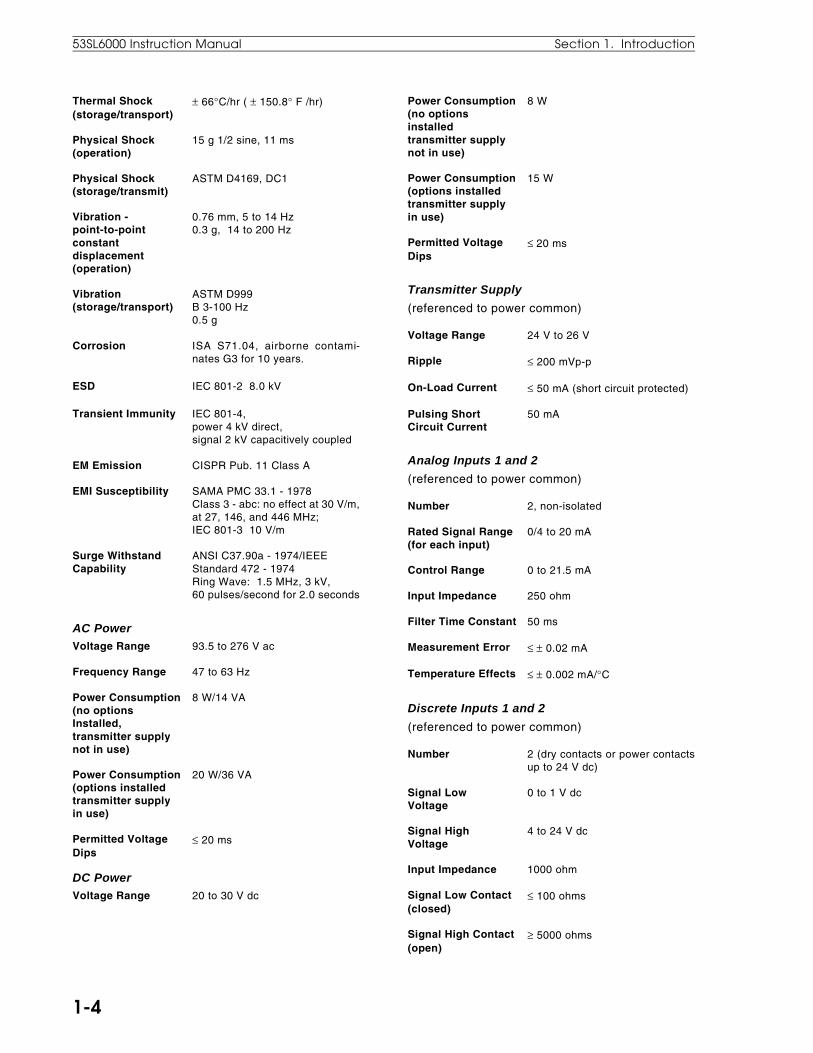
Thermal Shock ± 66°C/hr ( ± 150.8° F /hr)(storage/transport)
Physical Shock 15 g 1/2 sine, 11 ms(operation)
Physical Shock ASTM D4169, DC1(storage/transmit)
Vibration - 0.76 mm, 5 to 14 Hzpoint-to-point 0.3 g, 14 to 200 Hzconstant displacement(operation)
Vibration ASTM D999(storage/transport) B 3-100 Hz
0.5 g
Corrosion ISA S71.04, airborne contami-nates G3 for 10 years.
ESD IEC 801-2 8.0 kV
Transient Immunity IEC 801-4, power 4 kV direct, signal 2 kV capacitively coupled
EM Emission CISPR Pub. 11 Class A
EMI Susceptibility SAMA PMC 33.1 - 1978Class 3 - abc: no effect at 30 V/m,at 27, 146, and 446 MHz; IEC 801-3 10 V/m
Surge Withstand ANSI C37.90a - 1974/IEEECapability Standard 472 - 1974
Ring Wave: 1.5 MHz, 3 kV,60 pulses/second for 2.0 seconds
AC PowerVoltage Range 93.5 to 276 V ac
Frequency Range 47 to 63 Hz
Power Consumption 8 W/14 VA(no optionsInstalled,transmitter supplynot in use)
Power Consumption 20 W/36 VA(options installedtransmitter supplyin use)
Permitted Voltage ≤ 20 msDips
DC PowerVoltage Range 20 to 30 V dc
Power Consumption 8 W(no optionsinstalledtransmitter supplynot in use)
Power Consumption 15 W(options installedtransmitter supplyin use)
Permitted Voltage ≤ 20 msDips
Transmitter Supply
(referenced to power common)
Voltage Range 24 V to 26 V
Ripple ≤ 200 mVp-p
On-Load Current ≤ 50 mA (short circuit protected)
Pulsing Short 50 mACircuit Current
Analog Inputs 1 and 2
(referenced to power common)
Number 2, non-isolated
Rated Signal Range 0/4 to 20 mA(for each input)
Control Range 0 to 21.5 mA
Input Impedance 250 ohm
Filter Time Constant 50 ms
Measurement Error ≤ ± 0.02 mA
Temperature Effects ≤ ± 0.002 mA/°C
Discrete Inputs 1 and 2
(referenced to power common)
Number 2 (dry contacts or power contactsup to 24 V dc)
Signal Low 0 to 1 V dcVoltage
Signal High 4 to 24 V dcVoltage
Input Impedance 1000 ohm
Signal Low Contact ≤ 100 ohms(closed)
Signal High Contact ≥ 5000 ohms(open)
53SL6000 Instruction Manual Section 1. Introduction
1-4
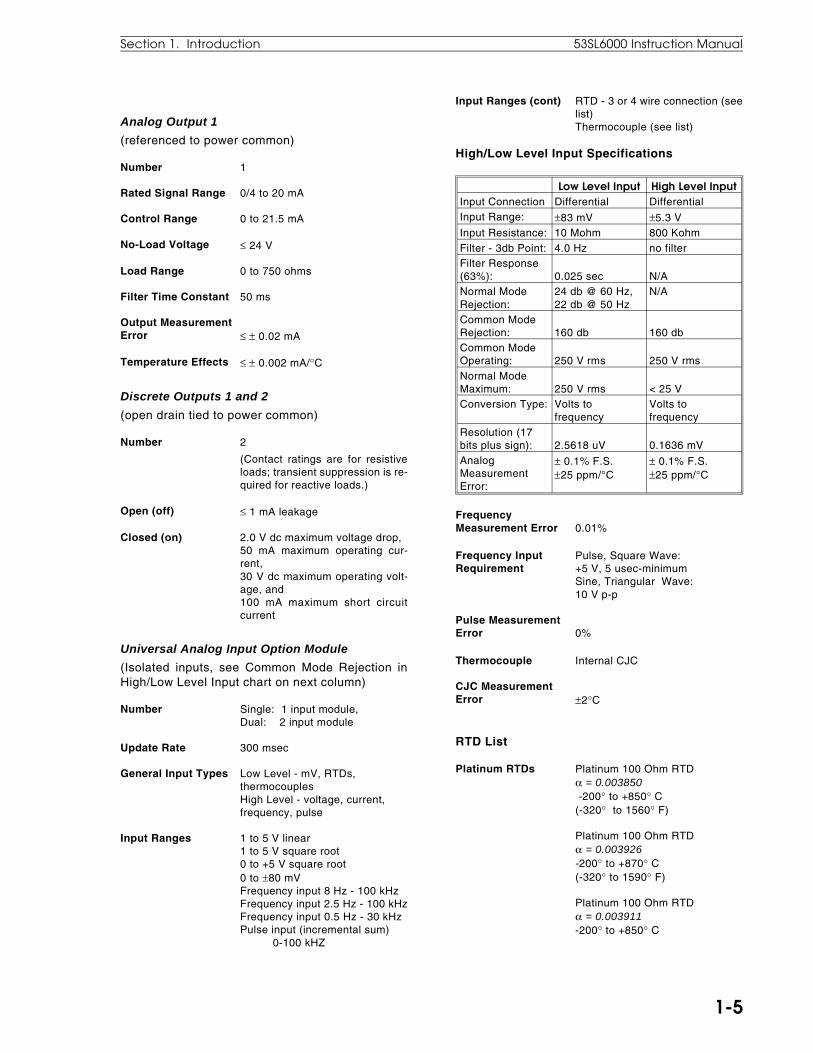
Analog Output 1
(referenced to power common)
Number 1
Rated Signal Range 0/4 to 20 mA
Control Range 0 to 21.5 mA
No-Load Voltage ≤ 24 V
Load Range 0 to 750 ohms
Filter Time Constant 50 ms
Output MeasurementError ≤ ± 0.02 mA
Temperature Effects ≤ ± 0.002 mA/°C
Discrete Outputs 1 and 2
(open drain tied to power common)
Number 2
(Contact ratings are for resistiveloads; transient suppression is re-quired for reactive loads.)
Open (off) ≤ 1 mA leakage
Closed (on) 2.0 V dc maximum voltage drop,50 mA maximum operating cur-rent,30 V dc maximum operating volt-age, and100 mA maximum short circuitcurrent
Universal Analog Input Option Module
(Isolated inputs, see Common Mode Rejection inHigh/Low Level Input chart on next column)
Number Single: 1 input module,Dual: 2 input module
Update Rate 300 msec
General Input Types Low Level - mV, RTDs,thermocouplesHigh Level - voltage, current,frequency, pulse
Input Ranges 1 to 5 V linear1 to 5 V square root0 to +5 V square root0 to ±80 mVFrequency input 8 Hz - 100 kHzFrequency input 2.5 Hz - 100 kHzFrequency input 0.5 Hz - 30 kHzPulse input (incremental sum) 0-100 kHZ
Input Ranges (cont) RTD - 3 or 4 wire connection (seelist)Thermocouple (see list)
High/Low Level Input Specifications
Low Level Input High Level InputInput Connection Differential DifferentialInput Range: ±83 mV ±5.3 VInput Resistance: 10 Mohm 800 KohmFilter - 3db Point: 4.0 Hz no filterFilter Response(63%): 0.025 sec N/ANormal ModeRejection:
24 db @ 60 Hz,22 db @ 50 Hz
N/A
Common ModeRejection: 160 db 160 dbCommon ModeOperating: 250 V rms 250 V rmsNormal ModeMaximum: 250 V rms < 25 VConversion Type: Volts to
frequencyVolts tofrequency
Resolution (17bits plus sign): 2.5618 uV 0.1636 mVAnalogMeasurementError:
± 0.1% F.S.±25 ppm/°C
± 0.1% F.S.±25 ppm/°C
FrequencyMeasurement Error 0.01%
Frequency Input Pulse, Square Wave:Requirement +5 V, 5 usec-minimum
Sine, Triangular Wave:10 V p-p
Pulse MeasurementError 0%
Thermocouple Internal CJC
CJC MeasurementError ±2°C
RTD List
Platinum RTDs Platinum 100 Ohm RTDα = 0.003850 -200° to +850° C(-320° to 1560° F)
Platinum 100 Ohm RTDα = 0.003926-200° to +870° C(-320° to 1590° F)
Platinum 100 Ohm RTDα = 0.003911-200° to +850° C
Section 1. Introduction 53SL6000 Instruction Manual
1-5
(-320° to 1560° F)
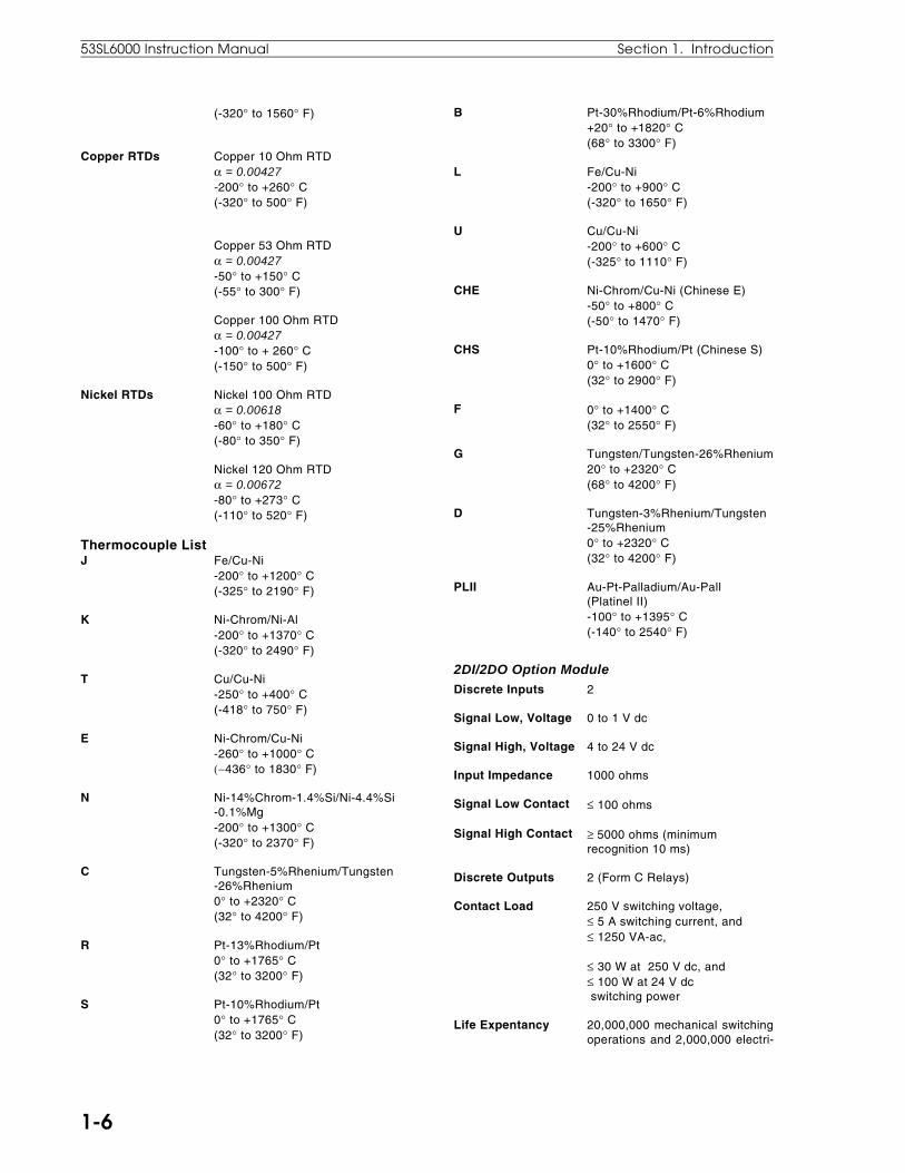
Copper RTDs Copper 10 Ohm RTDα = 0.00427-200° to +260° C(-320° to 500° F)
Copper 53 Ohm RTDα = 0.00427-50° to +150° C(-55° to 300° F)
Copper 100 Ohm RTDα = 0.00427-100° to + 260° C(-150° to 500° F)
Nickel RTDs Nickel 100 Ohm RTDα = 0.00618-60° to +180° C(-80° to 350° F)
Nickel 120 Ohm RTDα = 0.00672-80° to +273° C(-110° to 520° F)
Thermocouple ListJ Fe/Cu-Ni
-200° to +1200° C(-325° to 2190° F)
K Ni-Chrom/Ni-Al-200° to +1370° C(-320° to 2490° F)
T Cu/Cu-Ni-250° to +400° C(-418° to 750° F)
E Ni-Chrom/Cu-Ni-260° to +1000° C (−436° to 1830° F)
N Ni-14%Chrom-1.4%Si/Ni-4.4%Si-0.1%Mg-200° to +1300° C(-320° to 2370° F)
C Tungsten-5%Rhenium/Tungsten-26%Rhenium0° to +2320° C(32° to 4200° F)
R Pt-13%Rhodium/Pt0° to +1765° C(32° to 3200° F)
S Pt-10%Rhodium/Pt0° to +1765° C(32° to 3200° F)
B Pt-30%Rhodium/Pt-6%Rhodium+20° to +1820° C(68° to 3300° F)
L Fe/Cu-Ni-200° to +900° C(-320° to 1650° F)
U Cu/Cu-Ni-200° to +600° C(-325° to 1110° F)
CHE Ni-Chrom/Cu-Ni (Chinese E)-50° to +800° C(-50° to 1470° F)
CHS Pt-10%Rhodium/Pt (Chinese S)0° to +1600° C(32° to 2900° F)
F 0° to +1400° C(32° to 2550° F)
G Tungsten/Tungsten-26%Rhenium20° to +2320° C(68° to 4200° F)
D Tungsten-3%Rhenium/Tungsten-25%Rhenium0° to +2320° C(32° to 4200° F)
PLII Au-Pt-Palladium/Au-Pall(Platinel II)-100° to +1395° C(-140° to 2540° F)
2DI/2DO Option ModuleDiscrete Inputs 2
Signal Low, Voltage 0 to 1 V dc
Signal High, Voltage 4 to 24 V dc
Input Impedance 1000 ohms
Signal Low Contact ≤ 100 ohms
Signal High Contact ≥ 5000 ohms (minimumrecognition 10 ms)
Discrete Outputs 2 (Form C Relays)
Contact Load 250 V switching voltage,≤ 5 A switching current, and≤ 1250 VA-ac,
≤ 30 W at 250 V dc, and≤ 100 W at 24 V dc switching power
Life Expentancy 20,000,000 mechanical switchingoperations and 2,000,000 electri-
53SL6000 Instruction Manual Section 1. Introduction
1-6

cal 24 V/4 A ohmic Amp switchingoperations
Spark Suppressor In series 5nF/51 ohm with varistor420 Veff in parallel
Electrical Isolation 1000 V contact coil1000 V contact-contact1000 V between relays
CPU Cycle TimeInput Sample Rate 50 ms
Output Update Rate 50 ms
Display Update Rate 50 ms
Control RangesProportional (P) 1000% - 2%
Integral (I) 200 min/repeat - 0.02 min/repeat,0 is off.
Derivative (D) 8 min - 0.01 min, 0 is off
DisplayElement Type Red, green, and yellow LEDs
Digital Readouts 8.9 mm in height
two 4 digit, 7 segment digitalreadouts
one 3 digit, 7 segment digitalreadouts
Analog Bar Graphs two columns of 40 LEDs80.7 mm in height4.8 mm in width0 to 100% range2.5% bargraph operation resolutionred PV LEDsgreen SP LEDs
LED Indicators twelve LEDs: red, green, yellow
Keypad Seven positive tactile-feel keys
Section 1. Introduction 53SL6000 Instruction Manual
1-7

2.1 Inspection Inspect the equipment upon arrival for damage thatmay have occurred during shipment. If damage issuch that faulty operation is likely to result, do notinstall the controller and contact the ABB Automat-ion representative if purchased direct, or contactthe appropriate supplier for repair/replacement pro-cedures. Inspect the packing material before dis-carding it to prevent the loss of any additionalproduct literature that may have been included inthe shipment. Also inspect the controller data tagto ensure it has the correct power requirements forthe intended application (e.g., 120/240 V ac or 24 Vdc).
2.2 Site LocationThe 53SL6000 controller is designed to operate ona plant floor where the controller faceplate might beexposed to occassional wash-downs. See Section1.3 for the stated environmental specifications ofthe controller.
2.3 Panel MountingDimensions for single and multi-controller mount-ing in a single panel cutout are provided in Figure2-1.
2.3.1 Single Cutout Installation (NEMA4 Compliant)1. From the rear of the controller, slide on the
rubber O-ring so that it butts against the dis-play flange.
2. The applicable option modules can be installednow, before the controller is mounted in thepanel cutout, or after mounting. If installing theoption modules now, see Figure 2-7 to installthe universal analog input module, Figure 2-9to install the 2DI/2DO module, and Figure 2-12 to install the RS-232 or RS-485 module.This step can be skipped if none of these mod-ules were ordered with the controller.
3. Slide the controller through the panel cutoutand secure it in place using the two mountingbrackets as shown in Figure 2-1.
2.3.2 Multiple Cutout InstallationMulti-controller mounting collar part numbers areprovided in Table B-1, Parts List.
1. If it is desired to cushion the controller from thecollar, then slide on the rubber O-ring from the
rear of the controller so that it butts against thedisplay flange. This step is optional and notrequired.
2. The applicable option modules can be installedbefore each controller is mounted in the panelcutout, or after mounting. If installing the op-tion modules now, see Figure 2-7 to install theuniversal analog input module, Figure 2-9 toinstall the 2DI/2DO module, and Figure 2-12to install the RS-232 or RS-485 module.This step can be skipped if none of these mod-ules were ordered with the controllers.
3. Slide each controller through the mounting col-lar and panel cutout. Secure each controller inplace using the two mounting brackets asshown in Figure 2-1.
2.4 Power ConnectionsFigure 2-2 illustrates the power plug location on thecontroller backplane. The power plug is removableand can be pulled straight out from its backplaneconnector. The plug is scalloped on one side toensure proper insertion after the power wires areconnected.
WARNING: Instruments that are powered from anac line service constitute a potential electric shockhazard to the user; therefore, only qualifiedtechnicians should install the unit. Make certainthat the ac power lines are disconnected from theoperating branch circuit before attemptingelectrical connections.
NOTE: Installations are expected to have accessto a high quality, noise-free point of earthreference. Connection should be through a lowresistance (less than one ohm) lead wire directlyto the installation’s point of earth reference whichcan be an independent grounding rod or groundgrid mesh that penetrates the permanent moisturelevel below the frost line in accordance with Article250 of ANSI/NFPA 70, the National ElectricalCode, or other code(s) acceptable to the authorityhaving jurisdiction over the installation.
NOTE: In electrically noisy locations, use shieldedsignal wiring. Also, the power wiring should notbe routed in close proximity to signal wiring.
NOTE: Each power wire lead should be strippedto expose 1/4 inch (6.4 mm) conductor.
2.0 Installation and Power-Up Procedures
Section 2. Installation and Power-Up Procedures 53SL6000 Instruction Manual
2-1
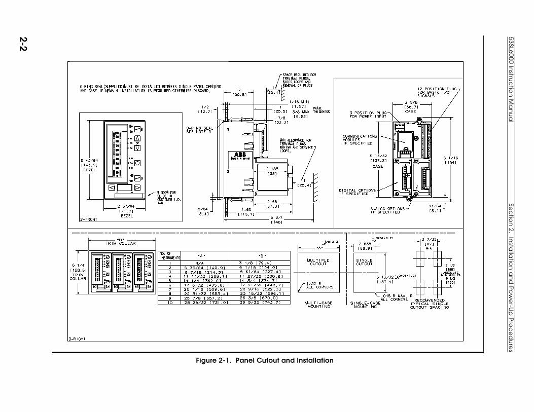
Figure 2-1. Panel Cutout and Installation
53SL6000 Instru
ctio
n M
an
ua
lSe
ctio
n 2. In
stalla
tion
an
d P
ow
er-U
p P
roc
ed
ure
s
2-2
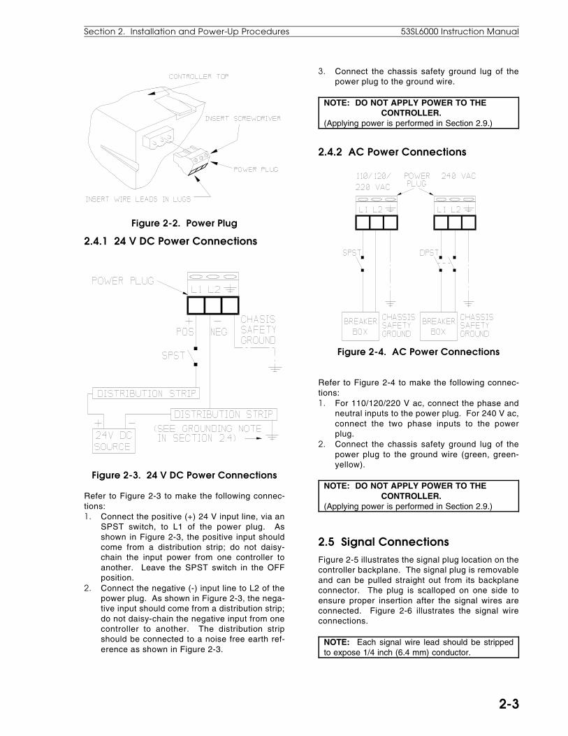
Figure 2-2. Power Plug
2.4.1 24 V DC Power Connections
Figure 2-3. 24 V DC Power Connections
Refer to Figure 2-3 to make the following connec-tions:1. Connect the positive (+) 24 V input line, via an
SPST switch, to L1 of the power plug. Asshown in Figure 2-3, the positive input shouldcome from a distribution strip; do not daisy-chain the input power from one controller toanother. Leave the SPST switch in the OFFposition.
2. Connect the negative (-) input line to L2 of thepower plug. As shown in Figure 2-3, the nega-tive input should come from a distribution strip;do not daisy-chain the negative input from onecontroller to another. The distribution stripshould be connected to a noise free earth ref-erence as shown in Figure 2-3.
3. Connect the chassis safety ground lug of thepower plug to the ground wire.
NOTE: DO NOT APPLY POWER TO THE CONTROLLER.(Applying power is performed in Section 2.9.)
2.4.2 AC Power Connections
Figure 2-4. AC Power Connections
Refer to Figure 2-4 to make the following connec-tions:1. For 110/120/220 V ac, connect the phase and
neutral inputs to the power plug. For 240 V ac,connect the two phase inputs to the powerplug.
2. Connect the chassis safety ground lug of thepower plug to the ground wire (green, green-yellow).
NOTE: DO NOT APPLY POWER TO THE CONTROLLER.(Applying power is performed in Section 2.9.)
2.5 Signal ConnectionsFigure 2-5 illustrates the signal plug location on thecontroller backplane. The signal plug is removableand can be pulled straight out from its backplaneconnector. The plug is scalloped on one side toensure proper insertion after the signal wires areconnected. Figure 2-6 illustrates the signal wireconnections.
NOTE: Each signal wire lead should be strippedto expose 1/4 inch (6.4 mm) conductor.
Section 2. Installation and Power-Up Procedures 53SL6000 Instruction Manual
2-3
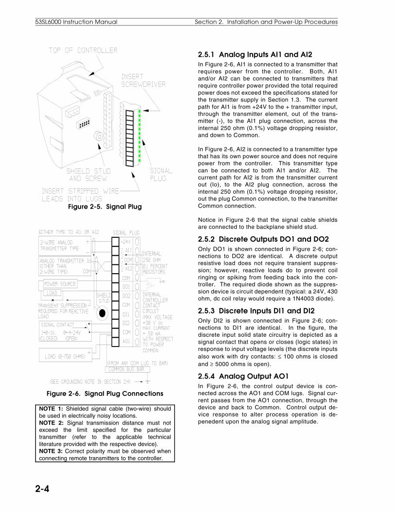
Figure 2-5. Signal Plug
Figure 2-6. Signal Plug Connections
NOTE 1: Shielded signal cable (two-wire) shouldbe used in electrically noisy locations.NOTE 2: Signal transmission distance must notexceed the limit specified for the particulartransmitter (refer to the applicable technicalliterature provided with the respective device).NOTE 3: Correct polarity must be observed whenconnecting remote transmitters to the controller.
2.5.1 Analog Inputs AI1 and AI2In Figure 2-6, AI1 is connected to a transmitter thatrequires power from the controller. Both, AI1and/or AI2 can be connected to transmitters thatrequire controller power provided the total requiredpower does not exceed the specifications stated forthe transmitter supply in Section 1.3. The currentpath for AI1 is from +24V to the + transmitter input,through the transmitter element, out of the trans-mitter (-), to the AI1 plug connection, across theinternal 250 ohm (0.1%) voltage dropping resistor,and down to Common.
In Figure 2-6, AI2 is connected to a transmitter typethat has its own power source and does not requirepower from the controller. This transmitter typecan be connected to both AI1 and/or AI2. Thecurrent path for AI2 is from the transmitter currentout (Io), to the AI2 plug connection, across theinternal 250 ohm (0.1%) voltage dropping resistor,out the plug Common connection, to the transmitterCommon connection.
Notice in Figure 2-6 that the signal cable shieldsare connected to the backplane shield stud.
2.5.2 Discrete Outputs DO1 and DO2Only DO1 is shown connected in Figure 2-6; con-nections to DO2 are identical. A discrete outputresistive load does not require transient suppres-sion; however, reactive loads do to prevent coilringing or spiking from feeding back into the con-troller. The required diode shown as the suppres-sion device is circuit dependent (typical: a 24V, 430ohm, dc coil relay would require a 1N4003 diode).
2.5.3 Discrete Inputs DI1 and DI2Only DI2 is shown connected in Figure 2-6; con-nections to DI1 are identical. In the figure, thediscrete input solid state circuitry is depicted as asignal contact that opens or closes (logic states) inresponse to input voltage levels (the discrete inputsalso work with dry contacts: ≤ 100 ohms is closedand ≥ 5000 ohms is open).
2.5.4 Analog Output AO1In Figure 2-6, the control output device is con-nected across the AO1 and COM lugs. Signal cur-rent passes from the AO1 connection, through thedevice and back to Common. Control output de-vice response to alter process operation is de-penedent upon the analog signal amplitude.
53SL6000 Instruction Manual Section 2. Installation and Power-Up Procedures
2-4

2.6 Universal Analog Input ModuleThis information applies to only those controllerswith an optional universal analog input module.
2.6.1 Universal Analog Input Module Backplane InstallationFigure 2-7 illustrates the universal analog inputmodule location on the controller backplane. Theuniversal input module is socket mounted and issecured to the backplane with two screws. Alsoshown in Figure 2-7 are the signal plugs AI3 (rightplug) and AI4 (left plug) that are screw mounted tothe universal analog input module (the plug mount-ing screws are not illustrated). Depending on theoption ordered, one (AI3) or both (AI3 and AI4) ofthese plugs will require installation and input con-nections. The plugs for AI3 and AI4 are identical;therefore, care should be taken to ensure eachplug is installed in its proper location. Each plug,however, is keyed to prevent inverted insertion intoits module connector.
Figure 2-7. Universal Analog Input Module
2.6.2 Universal Analog Input Module Signal WiringAs shown in Figure 2-7 (e.g., INSERT SCREW-DRIVER), the signal wire lug screws are accessedon the side of each plug.
Each analog input (AI3 and AI4) can accept onlyone device input configuration as illustrated in Fig-ure 2-8. Unused plug lugs can not be dedicatedto another input.
2.6.2.1 Thermocouple Connections and Burn-out DetectionTo ensure proper cold junction compensation(CJC) operation, the steps to wire a thermocoupleto the universal analog input module are as follows:
1. Prepare the thermocouple leads as shown inthe following illustration:
2. For dual universal analog input modules thatwill have one thermocouple connected, ensureit is installed on AI3 and that the other input isinstalled on AI4.
3. For dual universal analog input modules thatwill have only one terminal plug connected, theother terminal plug must still be installed on themodule for proper performance.
4. Thermocouple Burn-out Detection - A sshown in Figure 2-8, an open thermocoupledetection (OTD) current, which is very small, isprovided at pin 3 of each connector plug. If pin3 is wired to pin 1 and the thermocouple opens,then a positive temperature over range results.If pin 3 is wired to pin 2 and the thermocoupleopens, then a negative temperature over rangeresults.
NOTE: If an upscale or downscale openthermocouple detection (OTD) wire is installed aspart of the thermocouple connection, then the wireshould be 2 inches (50.8 mm) of 22AWG wire orlighter. Do not use longer or heavier gauge (e.g.,14AWG) wire.
5. The complete assembly will reach thermalequilibrium approximately 30 minutes after thecontroller is powered up (see Section 2.9, Ap-plying Power).
Section 2. Installation and Power-Up Procedures 53SL6000 Instruction Manual
2-5
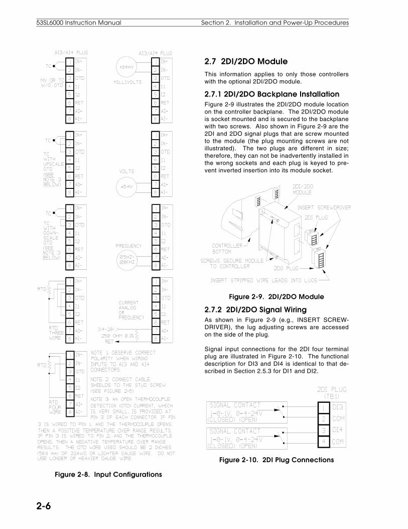
Figure 2-8. Input Configurations
2.7 2DI/2DO ModuleThis information applies to only those controllerswith the optional 2DI/2DO module.
2.7.1 2DI/2DO Backplane InstallationFigure 2-9 illustrates the 2DI/2DO module locationon the controller backplane. The 2DI/2DO moduleis socket mounted and is secured to the backplanewith two screws. Also shown in Figure 2-9 are the2DI and 2DO signal plugs that are screw mountedto the module (the plug mounting screws are notillustrated). The two plugs are different in size;therefore, they can not be inadvertently installed inthe wrong sockets and each plug is keyed to pre-vent inverted insertion into its module socket.
Figure 2-9. 2DI/2DO Module
2.7.2 2DI/2DO Signal WiringAs shown in Figure 2-9 (e.g., INSERT SCREW-DRIVER), the lug adjusting screws are accessedon the side of the plug.
Signal input connections for the 2DI four terminalplug are illustrated in Figure 2-10. The functionaldescription for DI3 and DI4 is identical to that de-scribed in Section 2.5.3 for DI1 and DI2.
Figure 2-10. 2DI Plug Connections
53SL6000 Instruction Manual Section 2. Installation and Power-Up Procedures
2-6
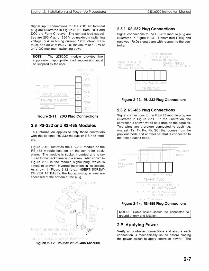
Signal input connections for the 2DO six terminalplug are illustrated in Figure 2-11. Both, DO1 andDO2 are Form C relays. The contact load capaci-ties are 250 V ac or 250 V dc maximum switchingvoltage; 5 A switching current; 1250 VA-ac maxi-mum, and 30 W at 250 V-DC maximum or 100 W at24 V-DC maximum switching power.
NOTE: The 2DI/2DO module provides linesuppression; appropriate load suppression mustbe supplied by the user.
Figure 2-11. 2DO Plug Connections
2.8 RS-232 and RS-485 ModulesThis information applies to only those controllerswith the optional RS-232 module or RS-485 mod-ule.
Figure 2-12 illustrates the RS-232 module or theRS-485 module location on the controller back-plane. The module is socket mounted and is se-cured to the backplane with a screw. Also shown inFigure 2-12 is the module signal plug, which iskeyed to prevent inverted insertion in its socket.As shown in Figure 2-12 (e.g., INSERT SCREW-DRIVER AT BASE), the lug adjusting screws areaccessed at the bottom of the plug.
Figure 2-12. RS-232 or RS-485 Module
2.8.1 RS-232 Plug ConnectionsSignal connections to the RS-232 module plug areillustrated in Figure 2-13. Transmitted (TxD) andreceived (RxD) signals are with respect to the con-troller.
Figure 2-13. RS-232 Plug Connections
2.8.2 RS-485 Plug ConnectionsSignal connections to the RS-485 module plug areillustrated in Figure 2-14. In the illustration, thecontroller is shown wired as a drop on the datalink.Two wires are therefore connected to each lug:one set (T+, T-, R+, R-, SC) that comes from theprevious node and another set that is connected tothe next datalink node.
Figure 2-14. RS-485 Plug Connections
NOTE: Cable shield should be connected toground at only one location.
2.9 Applying PowerVerify all controller connections and ensure eachconnection is mechanically sound before closingthe power switch to apply controller power. The
Section 2. Installation and Power-Up Procedures 53SL6000 Instruction Manual
2-7

controller powers up in the last state it was in be-fore power was removed.
2.9.1 Power-up SequenceThe power-up sequence is as follows:
1. At power-up, the controller performs a power-on self test which includes lighting all faceplateLEDs for three seconds to show they are work-ing.
2. After completing the power-on self test, statusinformation is presented in the dros. Duringstatus, both of the vertical bars have fiveequally spaced LEDs lit.
2a. If the power-on self test is successful, thedros wil l contain option identif icationcodes and the firmware revision level iden-tification for the next three seconds as de-scribed in Table 2-1.
Table 2-1. Controller Status Codes
dro Attribute Status CodeTop (red) Option A status
code.0 = no options.192 = 2DI/2DO.193 = Single Univer-sal Analog Input.194 = Dual Univer-sal Analog Input.
Middle(green)
Option B statuscode.
Bottom(yellow)
Firmware revisionlevel identifier.
Code must be crossreferenced torevision level.
2b. If a power-on self-test database memoryerror occurs, the nrAM error appears inthe top (red) dro and the controller haltsfurther operation. Return unit to ABBAutomation or distributor, as applicable.
3. After a successful power-on self test andstatus presentation, the controller enters op-erator mode, unless it was offline or executingthe controller confidence test when it was pow-ered-down.
Offline is indicated by four equally spacedpairs of lit LEDs in the green vertical bar.When offline, no control is being performedand all outputs are held at their values pre-vious to being placed in offline mode. (Formore information about operator mode seeSection 3.2, Operator Mode; for more informa-tion about the offline state, see Section 3.7,Offline Display Pattern.)
Reference Section B.4.6, Exiting the ControllerConfidence Test via the Faceplate Push Buttons, ifit is suspected that the controller was executing the
controller confidence tests when it was powered-down. Both vertical bars and all status indicatorLEDs, except the WD indicator, will be lit during thecontroller confidence test execution.
53SL6000 Instruction Manual Section 2. Installation and Power-Up Procedures
2-8

3.1 Display Panel OverviewAs shown in Figure 3-1, the controller display panelcontains three digital read-out (dro) fields, two ver-tical bar indicators, twelve function specific statusindicators, and seven push buttons (pbs). The dis-play panel is used to alter controller settings (whichin turn affect process operation), to monitor proc-ess operation, and to configure controller function-ality. (It is also used to commission the controller,which is described in Section 9.) Process opera-tion is altered and monitored with the controller inoperator mode; controller functionality is config-ured with the controller in engineer mode.
Figure 3-1. Display Panel Overview
3.2 Operator ModeThe colors red, green, and yellow are used to visu-ally partition the display panel into general operat-ing mode functional areas as follows:
• red - process variable presentation.
• green - setpoint presentation and control.
• yellow - output presentation and control.
Red: The red display area includes the left verticalbar, upper dro, and alarm status indicators (A1,A2). This display area is assigned to the processvariable input. The red vertical bar indicates theprocess variable as a percent of control range andthe red dro is the process variable in engineeringunits.
Green: The green display area includes the rightvertical bar, the dro immediately beneath it, theremote/local pb with its two status indicators, andthe setpoint up/down pbs. This display area is usu-ally assigned to setpoint indication and control, al-though the green vertical bar and dro can be usedto indicate a second process variable if the se-lected control scheme is an indicator. The greenvertical bar indicates the setpoint as a percent ofcontrol range and the green dro is the value inengineering units.
Yellow: The yellow display area includes the bot-tom dro, the auto/manual pb with its status indica-tors, the output pbs, and the two multistate (MS1,MS2) indicators. This display area is primarily as-signed to output indication and control. The yellowdro is an output value in percent of the scaled finalcontrol element travel range.
3.2.1 Operator Mode Panel Functions The operator mode panel functions are describedin Figure 3-2 on the next page. The figure hasthree major parts: an illustration of the controllerwith item number call-outs in the upper right, asupporting chart in the upper left that defines theOff/On/Blinking status indicator states, and a sum-mary chart at the bottom that lists the assignedfunctions of each item call-out by control scheme.The illustration item call-outs are defined in moredetail in Table 3-1.
As shown in Figure 3-2, many of the push buttonsand status indicators have identical functions in thedifferent control schemes; however, the indica-tor/loader (in.Ld) control scheme is the mostunique.
3.0 Display Panel
Section 3. Display Panel 53SL6000 Instruction Manual
3-1
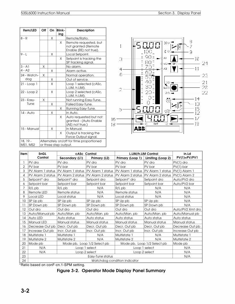
Item/LED Off On Blink-ing
Description
8 - R X Remote/Ratio.X Remote requested, but
not granted (RemoteEnable [RE] not true).
9 - L X Local Setpoint.X Setpoint is tracking the
SP tracking signal.3 - A14 - A2
X No alarm.X Alarm active.
24 - Watch- dog
X Normal operation.X Out of service.
21 - Loop 1 X Loop 1 selected (cASc,L.LiM, h.LiM).
22 - Loop 2 X Loop 2 selected (cASc,L.LiM, h.LiM).
23 - Easy- Tune
X Not running Easy-Tune.X Failed Easy-Tune.
X Running Easy-Tune.14 - Auto X In Auto.
X Auto requested but notgranted - (Auto Enable[AE] not true.)
15 - Manual X In Manual.X Output is tracking the
Force Output signal.18, 19 -MS1, MS2
Alternately on/off for time proportionedor three step output.
Item SnGL Control
cASc Control L.LiM/h.LiM Control in.LdPV(1)=PV/PV1Secondary (L1) Primary (L2) Primary (Loop 1) Limiting (Loop 2)
1 PV dro PV dro PV dro PV dro PV dro PV(1) dro2 PV bar PV bar PV bar PV bar PV bar PV(1) bar3 PV Alarm 1 status PV Alarm 1 status PV Alarm 1 status PV Alarm 1 status PV Alarm 1 status PV(1) Alarm 14 PV Alarm 2 status PV Alarm 2 status PV Alarm 2 status PV Alarm 2 status PV Alarm 2 status PV(1) Alarm 25 Setpoint* dro Setpoint* dro Setpoint dro Setpoint* dro Setpoint dro Auto/PV2 dro6 Setpoint bar Setpoint bar Setpoint bar Setpoint bar Setpoint bar Auto/PV2 bar7 R/L pb R/L pb N/A R/L pb N/A N/A8 Remote LED Remote status N/A Remote status N/A N/A9 Local LED Local status N/A Local status N/A N/A
10 SP Up pb SP Up pb SP Up pb SP Up pb SP Up pb N/A11 SP Down pb SP Down pb SP Down pb SP Down pb SP Down pb N/A12 Out dro Out dro Out dro Out dro Out dro Auto/PV2 Xmt dro13 Auto/Manual pb Auto/Man. pb Auto/Man. pb Auto/Man. pb Auto/Man. pb Auto/Manual pb14 Auto LED Auto status Auto status Auto status Auto status Auto status15 Manual LED Manual status Manual status Manual status Manual status Manual status16 Decrease Out pb Decr. Out pb Decr. Out pb Decr. Out pb Decr. Out pb Decrease Out pb17 Increase Out pb Incr. Out pb Incr. Out pb Incr. Out pb Incr. Out pb Increase Out pb18 Multistate 1 Multistate 1 N/A Multistate 1 N/A Multistate 1 19 Multistate 2 Multistate 2 N/A Multistate 2 N/A Multistate 220 Mode pb Mode pb, Loop 1/2 Select pb Mode pb, Loop 1/2 Select pb Mode pb21 N/A Loop 1 select Loop 1 select N/A22 N/A Loop 2 select Loop 2 select N/A23 Easy-Tune status N/A24 Watchdog condition indicator
*Ratio based on conF-cn.1-SPM setting.
Figure 3-2. Operator Mode Display Panel Summary
53SL6000 Instruction Manual Section 3. Display Panel
3-2

Table 3-1. Operator Mode Display Items
Item Call-Out Description1 PV dro It is the process variable
value in engineering units.2 PV bar It indicates the process
variable percent of controlrange.
3 PV Alarm 1Status
When active, it indicatesalarm 1 of the selectedalarm index limits (e.g.high/low alarms; high, high-high alarms; etc.) was notwithin tolerable limits.For high/low alarms, anactive Alarm 1 LEDindicates the the PVexceeded the highalarmed value.
4 PV Alarm 2Status
When active, it indicatesalarm 2 of the selectedalarm index limits (e.g.high/low alarms; low, low-low alarms; etc.) was notwithin tolerable limits. Forhigh/low alarms, an activeAlarm 2 LED indicates thePV fell below the lowalarmed value.
5 Setpoint dro It is the setpoint value inengineering units or a ratiosetpoint.
6 Setpoint bar It indicates the setpointpercent of control range.It also produces a stripedpattern when thecontroller is offline.
7 R/LPushButton
Generally, it is used toselect the setpoint source:remote or local setpointcontrol. Remote setpointcontrol requires an activeRemote Enable. For ratiocontrol, it is used to selectratio or standard control.
8 RemoteSetpoint Status
It indicates remotesetpoint is selected withthe R/L push button. Seeitem 7 above and the LEDchart in Figure 3-2.
9 LocalSetpointStatus
It indicates the local ortracking setpoint isselected with the R/L pushbutton. See item 7 aboveand the LED chart in Figure3-2.
10 SetpointUpPushButton
Pressing this push buttonincreases the localsetpoint or ratio setpointvalue. See Table 3-2 forsetpoint mode selections.
Table 3-1. Operator Mode Display Items
Item Call-Out Description11 Setpoint
Down pbPressing this push buttondecreases the localsetpoint or ratio setpointvalue. See Table 3-2 forsetpoint mode selections.
12 Out dro It is the control output as apercent of control range.It can also be used todisplay an externallygenerated signal such as aproportional speedfloating control valveposition indication.
13 A/MPushButton
It is used to select auto ormanual control. If auto isselected and Auto Enableis active, then the output isdetermined by thecontroller PID algorithm. Ifmanual is selected, theoutput is determined bythe decrease/increase outpush buttons.
14 AutoStatus
It indicates auto operationis selected with the A/Mpush button. See the LEDchart in Figure 3-2.
15 ManualStatus
It indicates manualoperation is selected withthe A/M push button. Seethe LED chart in Figure 3-2.
16 Decrease Out PushButton
When in manualoperation, pressing thispush button causes theoutput to decrease.
17 Increase Out Push Button
When in manualoperation, pressing thispush button causes theoutput to increase.
18 Multistate 1Indicators
These two indicatorsactivate to show thedirection of the discretecontrol output.
19 Multistate 2Indicators
Section 3. Display Panel 53SL6000 Instruction Manual
3-3

Table 3-1. Operator Mode Display Items
Item Call-Out Description20 Select Mode
and Loop 1/2Push Button
Pressing this pushbutton in operatormode with an activetwo loop controlscheme (cASc, L.LiM, orh.LiM) selects the loopunder display panelcontrol. It toggles fromone loop to the othereach time it is pressed.If this push button isheld for three seconds,it causes engineermode to be entered.Pressing it in engineermode causes a returnto operator mode.
21 Loop 1SelectIndicator
These indicators are forthe two loop controlschemes cASc, L.LiM,and h.LiM. Either oneof these two indicatorswill activate to showwhich loop is underdisplay panel controlas selected by theMode push button.
22 Loop 2SelectIndicator
23 Easy-TuneStatus
This status indicatorblinks during Easy-Tuneoperation. A steady-state-on conditionindicates Easy-Tuneterminated with anerror. It stops blinkingwhen Easy-Tunecompletes successfully.
24 WatchdogCondition Indicator
This indicator activateswhenever thecontroller detects aninternal processorfailure. When active,all outputs are forcedto their power-off state.Attempt to restart thecontroller by cyclingpower.
Table 3-2. Setpoint Up/Down Push Buttons
Display Panel ActionR/L PB (7)
SPM*R LED(8)
L LED(9)
Alter standard SP value. Y Std
No SP control. Y Std
Alter standard SP value. Y K-SP
Alter ratio SP value. Y K-SP
*SPM settings (Std or K-SP) are made in engineermode, which is described later in Section 3.
3.3 Auxiliary Operator AccessTo facilitate operator access for auxiliary data inputand selected parameter modification, an engineermode oPEr menu is provided. This menu allowsdisplay panel entry of logical and analog signalconstants, process variable alarm values, high/lowoutput limit values, and PID values. It also pro-vides operator capabilities to execute the Easy-Tune sequence. Access to menu i tems iscontrolled through the conF-oPr enabling parame-ters. Because the oPEr menu parameters and theircorresponding conF-oPr enabling parameters areaccessed in engineer mode, they are described inTables 3-3 and 3-4, which appear later as part ofthe engineer mode information.
3.4 Operator Mode Overflow/ Underflow IndicationOverflow indicators are plus signs (+) and under-flow indicators are negative signs (-). Illustrationsof the overflow and underflow conditions are pro-vided in Figure 3-3. They appear in the affecteddro and are decimal point sensitive. If these indica-tors repeatedly appear, the decimal point should berepositioned with the conF-cn.1(cn.2)-dP parame-ter described in Table 7-3. Adjusting this parame-ter requires knowledge of engineer mode, which isdescribed next in this section.
Figure 3-3. Overflow/Underflow Indicators
53SL6000 Instruction Manual Section 3. Display Panel
3-4

3.5 Engineer ModeThe controller parameters and path connectionsare configured in engineer mode. Engineer modeis also used to initiate the Easy-Tune sequence(see Section 9.8). This mode is entered when themode push button is held pressed for an extendedperiod of approximately 3 seconds, at which timethe oPEr menu prompt appears in the green dro.
3.5.1 Engineer Mode Display PanelThe display panel functions for engineer mode aredescribed in Figure 3-4 as follows:
Figure 3-4. Engineer Mode Display Panel
3.5.2 Engineer Mode Hieracrhical StructureEngineer mode is a hierarchical structure of nestedprompt layers that can be four levels deep; thegeneral order of selection is:
• Level 1, Menu - After engineer mode is ac-cessed with the mode push button, each menuprompt can be displayed sequentially by press-ing the scroll forward pb. The menu promptsare three major display panel paths: oPEr,ProG, and conF. The ProG and conF pathscan each be protected with their own uniquepass-key. The three menu prompts are de-scribed as follows:
1. oPEr (operator) - provides quick accessfor operators to display and configure com-
mon parameters such as alarm limits,deadband, etc. (This path skips level 2,module described below.)
2. ProG (Program) - is selected to enter reg-ister values, formula constants, and tomake path connections. Parameters en-tered in this menu will force the controlleroffline. It is used primarily by engineeringpersonnel.
3. conF (Configure) - is selected to configureonline database parameters; it is used pri-marily by engineering personnel.
• Level 2, Module Select - used to select a spe-cific controller functional element (e.g., theprompt Ai.1 for analog input 1). The full pathname is indicated by menu-module (e.g., conF-Ai.1). The module selection is skipped in theoPEr menu path.
• Level 3, Parameter Select - used to select aspecific parameter from a list of module pa-rameters (e.g., the parameter prompt SPAn un-der Ai.1). The full path name is indicated bymenu-module-parameter (e.g., conF-Ai.1-SPAn).
• Level 4, Edit - this is where a value is enteredfor the displayed parameter or a selection froma list of values or mnemonics is made.
3.5.2.1 Editing a Parameter Figure 3-5 illustrates the steps to edit a parameterin engineer mode. In the illustration a parameterselection is made; some parameters require a nu-meric value to be entered. The process to edit aparameter is reiterative:
• When engineer mode is entered, the oPErmenu prompt (level 1) appears in the greendro. The menu prompts are scrolled and oneis selected.
• Selecting a menu prompt causes the first mod-ule prompt (level 2) to appear in the yellow dro.The module prompts of the selected menu arescrolled and one is selected.
• Selecting a module prompt causes the first pa-rameter prompt (level 3) to appear; it replacesthe menu prompt in the green dro. The pa-rameter prompts of the selected module arescrolled and one is selected.
• Selecting a parameter prompt causes the firstedit entry prompt (level 4) to appear in the reddro. An edit input list is scrolled and an item isselected or a numeric value is entered.
Section 3. Display Panel 53SL6000 Instruction Manual
3-5

Figure 3-5. Editing a Parameter
NOTE 1: There is a 12.5 second time-out thatoccurs if a parameter prompt is not selected inengineer mode.NOTE 2: oPEr and conF parameter changes takeaffect immediately. If a ProG menu parameter isedited, the controller goes to the offline conditionin which no control action is performed.
3.5.2.2 Deselecting and Scrolling BackwardFigure 3-6 illustrates how to move through the vari-ous modules and their parameters by using thedeselect and scroll backward push buttons. Figure3-6 begins with the last level 4 edit select step inFigure 3-5 where the bASE parameter of the Ai.2module was updated. The object in Figure 3-6 is toexit the Ai.2 module after the bASE parameter hasbeen updated and to access the Ai.1 module whereany one of its parameters can be scrolled and se-lected for updating.
3.5.2.3 Editing a Numeric ValueIf a parameter value must be entered in the red dro,different editing steps must be performed thanwhen a selection is made from an item list. Figure3-7 illustrates these steps; it assumes engineermode has been entered, and the menu, module,and parameter have been selected. The parameterconF-Ai.1-SPAn will be edited from 100.0 to 275.0.Only the red dro showing the conF-Ai.1-SPAnvalue appears in the illustration.
Figure 3-8 illustrates changing the conF-Ai.1-SPAnvalue from 100.0 to 10.00 by moving the decimalpoint. It assumes engineer mode has been en-tered, and the menu, module, and parameter havebeen selected.
53SL6000 Instruction Manual Section 3. Display Panel
3-6

Figure 3-6. Deselecting and ScrollingBackward
Figure 3-7. Editing a Red dro Value
Figure 3-8. Moving the Red dro DecimalPoint
3.5.2.4 Editing the Tag ParameterThe tAG is one parameter where an alphanumeric,rather than a numeric, can be entered. It occurswhen the datalink controller conF-SYS-tAG pa-rameter must be configured. Because four charac-ters maximum can be displayed at any one time inthe red dro, using the shift right push button inengineer mode allows the ten character positionsto be displayed as follows:
0123 → 3456 → 6789
The bold characters are those that can be changedwith each four position display.
Characters are selected for each position with thescroll forward/backward push buttons in a mannerdescribed in Figure 3-7. The procedure to edit thetag is described in Figure 3-9. It assumes theconF-SYS-tAG parameter is already accessed.
Section 3. Display Panel 53SL6000 Instruction Manual
3-7

Figure 3-9. Editing a tAG
3.6 Entering a Pass-KeyIn engineering mode, access to the ProG and conFmenus can be selectively restricted, as each menuhas its own pass-key capabilities. A pass-key is afour digit number that must be entered when amenu is selected; otherwise, access to moduleprompts in that menu are prohibited. Figure 3-10illustrates the key display that appears if a menu ispass-key protected.
Figure 3-10. KEY? Prompt
The correct pass-key must be entered in the reddro with the following procedure:
1. Press the scroll forward pb until the desirednumber for the first digit appears (assumesfirst digit is not a zero).
2. Press the position select right pb; the secondzero starts blinking.
3. Repeat steps 1 and 2 to enter all four pass-keydigits.
4. Press the enter pb; if the pass-key is correctengineer mode functions are permitted for thatmenu.
NOTE: If the pass-key can not be recalled, thenthe database must be defaulted using theprocedure described in Section B.5.
3.6.1 Configuring a Pass-KeyTo configure a conF (or ProG) pass-key, the follow-ing steps must be performed:1. Enter engineer mode by pressing and holding
the mode pb until a menu prompt appears inthe green dro.
2. Press the scroll forward pb until conF (ProG)appears in the green dro.
3. Press the enter pb to accept the conF (ProG)menu.
4. If KEY does not appear in the yellow dro, pressthe scroll forward pb until it does.
5. Press the enter pb to select the KEY prompt.cKEY (PKEY) appears in the green dro.It is assumed the pass-key was never config-ured before and that four zeros appear in thered dro:
6. Press the enter pb; the leftmost number (zero)in the red dro blinks.
7. Press the scroll forward pb until the desirednumber appears (assumes zero wi l l bechanged to a different number).
8. Press the shift right pb; the next zero startsblinking.
9. Repeat steps 7 and 8 until all four pass-keydigits are entered.
10. Press the enter pb to enter the pass-key.11. Press the mode pb to exit engineer mode.
3.7 Offline Display PatternThe controller offline state is indicated by four acti-vated double LED markers along the green verticalbar as shown in Figure 3-11. The remainder of thevertical bar is dark.
Events that can cause the controller to be offlineare as follows:
• If a ProG menu parameter is altered in engi-neer mode , it causes the controller to immedi-ately go offline,
53SL6000 Instruction Manual Section 3. Display Panel
3-8
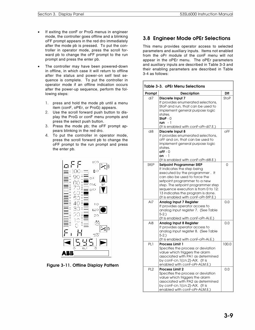
• If exiting the conF or ProG menus in engineermode, the controller goes offline and a blinkingoFF prompt appears in the red dro immediatelyafter the mode pb is pressed. To put the con-troller in operator mode, press the scroll for-ward pb to change the oFF prompt to the runprompt and press the enter pb.
• The controller may have been powered-downin offline, in which case it will return to offlineafter the status and power-on self test se-quence is complete. To put the controller inoperator mode if an offline indication occursafter the power-up sequence, perform the fol-lowing steps:
1. press and hold the mode pb until a menuitem (conF, oPEr, or ProG) appears.
2. Use the scroll forward push button to dis-play the ProG or conF menu prompts andpress the select push button.
3. Press the mode pb; the oFF prompt ap-pears blinking in the red dro.
4. To put the controller in operator mode,press the scroll forward pb to change theoFF prompt to the run prompt and pressthe enter pb.
Figure 3-11. Offline Display Pattern
3.8 Engineer Mode oPEr SelectionsThis menu provides operator access to selectedparameters and auxiliary inputs. Items not enabledfrom the oPr module of the conF menu will notappear in the oPEr menu. The oPEr parametersand auxiliary inputs are described in Table 3-3 andtheir enabling parameters are described in Table3-4 as follows:
Table 3-3. oPEr Menu Selections
Prompt Description Dftdi7 Discrete Input 7
It provides enumerated selections,StoP and run, that can be used toimplement general purpose logicstates.StoP - 0run - 1(It is enabled with conF-oPr-di7.E.)
StoP
di8 Discrete Input 8It provides enumerated selections,oFF and on, that can be used toimplement general purpose logicstates.oFF - 0on - 1(It is enabled with conF-oPr-di8.E.)
oFF
StEP Setpoint Programmer StEPIt indicates the step beingexecuted by the programmer . Itcan also be used to force thesetpoint programmer to a newstep. The setpoint programmer stepsequence execution is from 0 to 12;13 indicates the program is done.(It is enabled with conF-oPr-StP.E.)
0
Ai7 Analog Input 7 RegisterIt provides operator access toanalog input register 7. (See Table5-2.)(It is enabled with conF-oPr-Ai.E.)
0.0
Ai8 Analog Input 8 RegisterIt provides operator access toanalog input register 8. (See Table5-2.)(It is enabled with conF-oPr-Ai.E.)
0.0
PL1 Process Limit 1Specifies the process or deviationvalue which triggers the alarmassociated with PA1 as determinedby conF-cn.1(cn.2)-AiX. (It isenabled with conF-oPr-ALM.E.)
100.0
PL2 Process Limit 2Specifies the process or deviationvalue which triggers the alarmassociated with PA2 as determinedby conF-cn.1(cn.2)-AiX. (It isenabled with conF-oPr-ALM.E.)
0.0
Section 3. Display Panel 53SL6000 Instruction Manual
3-9
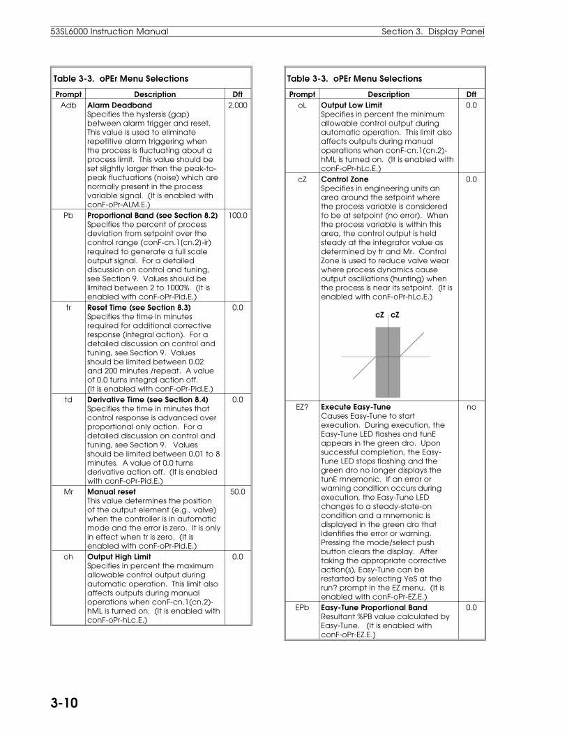
Table 3-3. oPEr Menu Selections
Prompt Description DftAdb Alarm Deadband
Specifies the hystersis (gap)between alarm trigger and reset.This value is used to eliminaterepetitive alarm triggering whenthe process is fluctuating about aprocess limit. This value should beset slightly larger then the peak-to-peak fluctuations (noise) which arenormally present in the processvariable signal. (It is enabled withconF-oPr-ALM.E.)
2.000
Pb Proportional Band (see Section 8.2)Specifies the percent of processdeviation from setpoint over thecontrol range (conF-cn.1[cn.2]-ir)required to generate a full scaleoutput signal. For a detaileddiscussion on control and tuning,see Section 9. Values should belimited between 2 to 1000%. (It isenabled with conF-oPr-Pid.E.)
100.0
tr Reset Time (see Section 8.3) Specifies the time in minutesrequired for additional correctiveresponse (integral action). For adetailed discussion on control andtuning, see Section 9. Valuesshould be limited between 0.02and 200 minutes /repeat. A valueof 0.0 turns integral action off.(It is enabled with conF-oPr-Pid.E.)
0.0
td Derivative Time (see Section 8.4)Specifies the time in minutes thatcontrol response is advanced overproportional only action. For adetailed discussion on control andtuning, see Section 9. Valuesshould be limited between 0.01 to 8minutes. A value of 0.0 turnsderivative action off. (It is enabledwith conF-oPr-Pid.E.)
0.0
Mr Manual resetThis value determines the positionof the output element (e.g., valve)when the controller is in automaticmode and the error is zero. It is onlyin effect when tr is zero. (It isenabled with conF-oPr-Pid.E.)
50.0
oh Output High LimitSpecifies in percent the maximumallowable control output duringautomatic operation. This limit alsoaffects outputs during manualoperations when conF-cn.1(cn.2)-hML is turned on. (It is enabled withconF-oPr-hLc.E.)
0.0
Table 3-3. oPEr Menu Selections
Prompt Description DftoL Output Low Limit
Specifies in percent the minimumallowable control output duringautomatic operation. This limit alsoaffects outputs during manualoperations when conF-cn.1(cn.2)-hML is turned on. (It is enabled withconF-oPr-hLc.E.)
0.0
cZ Control ZoneSpecifies in engineering units anarea around the setpoint wherethe process variable is consideredto be at setpoint (no error). Whenthe process variable is within thisarea, the control output is heldsteady at the integrator value asdetermined by tr and Mr. ControlZone is used to reduce valve wearwhere process dynamics causeoutput oscillations (hunting) whenthe process is near its setpoint. (It isenabled with conF-oPr-hLc.E.)
cZ cZ
0.0
EZ? Execute Easy-TuneCauses Easy-Tune to startexecution. During execution, theEasy-Tune LED flashes and tunEappears in the green dro. Uponsuccessful completion, the Easy-Tune LED stops flashing and thegreen dro no longer displays thetunE mnemonic. If an error orwarning condition occurs duringexecution, the Easy-Tune LEDchanges to a steady-state-oncondition and a mnemonic isdisplayed in the green dro thatidentifies the error or warning.Pressing the mode/select pushbutton clears the display. Aftertaking the appropriate correctiveaction(s), Easy-Tune can berestarted by selecting YeS at therun? prompt in the EZ menu. (It isenabled with conF-oPr-EZ.E.)
no
EPb Easy-Tune Proportional BandResultant %PB value calculated byEasy-Tune. (It is enabled with conF-oPr-EZ.E.)
0.0
53SL6000 Instruction Manual Section 3. Display Panel
3-10
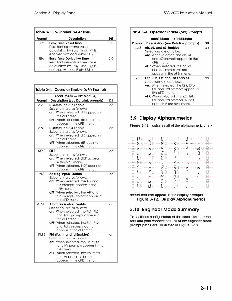
Table 3-3. oPEr Menu Selections
Prompt Description DftEtr Easy-Tune Reset Time
Resultant reset time valuecalculated by Easy-Tune. (It isenabled with conF-oPr-EZ.E.)
0.0
Etd Easy-Tune Derivative TimeResultant derivative time valuecalculated by Easy-Tune. (It isenabled with conF-oPr-EZ.E.)
0.0
Table 3-4. Operator Enable (oPr) Prompts
(conF Menu → oPr Module)Prompt Description (see Datalink prompts) Dft
di7.E Discrete Input 7 EnableSelections are as follows:on: When selected, di7 appears in the oPEr menu.oFF: When selected, di7 does not appear in the oPEr menu.
on
di8.E Discrete Input 8 EnableSelections are as follows:on: When selected, di8 appears in the oPEr menu.oFF: When selected, di8 does not appear in the oPEr menu.
on
StP.E StEPSelections are as follows:on: When selected, StEP appears in the oPEr menu.oFF: When selected, StEP does not appear in the oPEr menu.
on
Ai.E Analog Inputs EnableSelections are as follows:on: When selected, the Ai7 and Ai8 prompts appear in the oPEr menu.oFF: When selected, the Ai7 and Ai8 prompts do not appear in the oPEr menu.
on
ALM.E Alarm Indicators EnableSelections are as follows:on: When selected, the PL1, PL2 and Adb prompts appear in the oPEr menu.oFF: When selected, the PL1, PL2 and Adb prompts do not appear in the oPEr menu.
on
Pid.E Pid (Pb, tr, and td Enables)Selections are as follows:on: When selected, the Pb, tr, td, and Mr prompts appear in the oPEr menu.oFF: When selected, the Pb, tr, td, and Mr prompts do not appear in the oPEr menu.
on
Table 3-4. Operator Enable (oPr) Prompts
(conF Menu → oPr Module)Prompt Description (see Datalink prompts) DfthLc.E oh, oL, and cZ Enables
Selections are as follows:on: When selected, the oh, oL, and cZ prompts appear in the oPEr menu.oFF: When selected, the oh, ol, and cZ prompts do not appear in the oPEr menu.
on
EZ.E EZ?, EPb, Etr, and Etd EnablesSelections are as follows:on: When selected, the EZ?, EPb, Etr, and Etd prompts appear in the oPEr menu.oFF: When selected, the EZ?, EPb, Etr, and Etd prompts do not appear in the oPEr menu.
on
3.9 Display AlphanumericsFigure 3-12 illustrates all of the alphanumeric char-
acters that can appear in the display prompts.Figure 3-12. Display Alphanumerics
3.10 Engineer Mode SummaryTo facilitate configuration of the controller parame-ters and path connections, all of the engineer modeprompt paths are illustrated in Figure 3-13.
Section 3. Display Panel 53SL6000 Instruction Manual
3-11

Figure 3-13. Engineer Mode Prompt Path Summary
53SL6000 Instru
ctio
n M
an
ua
lSe
ctio
n 3. D
ispla
y Pa
ne
l
3-12

4.1 Simplified Block DiagramAs shown in Figure 4-1 below, the internal opera-tions of the 53SL6000 Controller can be classifiedinto nine major functional areas. An overview ofthese functional areas is provided in this section;additional information is provided in Sections 5through 7.
NOTE: Although external analog connections tothe controller are two standard inputs, two optionalinputs, and one output, there are in fact eightanalog input registers (AI1-8) and three analogoutput (AO1-3) registers available in the controllerdatabase. The discrete digital externalconnections include two standard inputs, twooptional inputs, two standard outputs, and twooptional outputs. There are, however, eightdiscrete input database registers (DI1- DO8) andeight discrete output database registers (DO1-DO8). Registers not assigned to standard oroptional external I/O functions can be loaded withconstant values to simulate known process eventsor hold process values for access through datalinkcommunications or for display.
1. Analog Inputs 1-4 (AI1-4) - accept the 0/4- 20mA input signals. Analog inputs 3 and 4 re-quire the universal analog input module. Thesignal values are stored in the analog regis-ters. There are eight analog input registers,AI1-AI8. Analog input registers AI5-AI8 do notaccept external signals, but can be loaded withconstant values.
2. Discrete Inputs 1-4 (DI1-4) - accept voltages0-1 V or 4-24 V, which are converted to logiclevels 1 and 0 respectively. Digital inputs 3and 4 require the 2DI/2DO module. There are
eight digital input registers, DI1-DI8. Digitalinput registers DI5-DI8 do not accept externalsignals, but can be loaded with logic level val-ues 0 or 1.
3. Characterizer - provides four operating modes,three of which are used to modify input signalvalues before being passed on to the analogmath function block or control scheme block;the other operating mode generates a rampand hold output value. The four operatingmodes are as follows:
• Five third order polynomial segments
• Twelve segment linearizer
• Setpoint programmer (ramp and hold)
• Digital-to-Analog converter
4. Math Function Block - provides nine differentequations for analog input signal augmenta-tion. The equations are as follows:
• Algebraic
• Summation
• Polynomial
• Power
• Logarithmic
• Limiter
• Selector
• Linear Gas Flow Compensation
• Square Root Gas Flow Compensation
4.0 Functional Overview
Figure 4-1. Simplified Controller Block Diagram
Section 4. Functional Overview 53SL6000 Instruction Manual
4-1

5. Discrete Input Logic Blocks - two input logicblocks permit discrete input signals to be eventgated with internal controller signals accordingto any one of eight specified logic functions.The eight logic functions are as follows:
• A OR B
• A AND B
• A XOR B
• A OR NOT B
• A AND NOT B
• NOT A OR B
• NOT A AND B
• NOT A XOR B
6. Control Scheme Block - five selectable controlscheme applications that calculate and pro-duce the necessary control output signal forthe process. The five control schemes are asfollows:
• SnGL - Single Loop
• cASc - Single Station Cascade
• L.LiM - Low Limiter (High Override)
• h.LiM - High Limiter (Low Override)
• in.Ld - Indicator/Loader
7. Discrete Output Logic Blocks - two output logicblocks that permit internal controller signals tobe event gated according to any one of eightspecified logic functions (see item 5, DiscreteInput Logic Blocks for functions).
8. Analog Output - there are three analog outputregisters, AO1-AO3. Analog output 1 (AO1) isassociated with the standard 0-100 outputvalue that produces a 0/4-20 mA signal to drivethe final control element or is applied as inputto another controller. Analog output registersAO2 and AO3 do not provide external signals,but serve as a loop-back to the math functionblock and control scheme block (the loop-backpath is not shown in the illustration).
9. Discrete Outputs 1-4 (DO1-4) - there are eightdigital output registers, DO1-DO8. DO1 andDO2 provide outputs that may be used to acti-vate pumps, alarms, etc. Discrete outputs 3and 4 require the 2DI/2DO module, which pro-vides relay outputs capable of higher currentloads than DO1 and DO2. DO3 and DO4 aregenerally sufficient as the two driver outputsfor time proportional or three step output driv-
ers, which are digital outputs used instead ofthe continuous 0/4-20 mA signal. Digital out-put registers DO5-DO8 have no associatedhardware, but DO7 and DO8 serve as loop-back registers to the math function block orinput logic blocks (the loop-back path is notshown in the illustration).
4.2 Detailed Block DiagramA more detailed functional block diagram of thecontroller is illustrated in Figure 4-2. The illustra-tion depicts processing as divided into analog con-trol (upper half) and discrete digital control (lowerhalf). The nine major functional areas are pre-sented with an emphasis on the available inputpath selections. Additional information for each ofthe nine functional areas is provided in Sections 5through 7.
1. Analog Inputs 1-8 (AI1-8) - the two standard(AI1 and AI2) and two optional inputs (AI3 andAI4) are identified. The push buttons next toAI7 and AI8 represent operator access tothese registers via the oPEr menu. Access tothese registers must be enabled with the conF-oPr-Ai.E parameter; otherwise, they will notappear in the oPEr prompt list.
2. Discrete Inputs 1-8 (DI1-8) - the two standard(DI1 and DI2) and two optional inputs (DI3 andDI4) are identified. Each DI register has twooutputs; one of the outputs is inverted and isindicated with a slash (/) across the connectionT-bar. The push buttons next to DI7 and DI8represent operator access to these registersvia the oPEr menu. Access to these registersmust be enabled from the conF-oPr-di7.E andconF-oPr-di8.E parameters; otherwise, theywill not appear in the oPEr prompt list.
3. Characterizer - is depicted as a five pin plug-able element, which can be inserted into one ofthe track locations of the math function block orcontrol scheme block. It intercepts the signalvalue before the math function block or controlscheme and augments that value as deter-mined by the selected operating mode (exceptfor the programmer mode, which generates anindependent signal based on time and config-ured data). The characterizer output is appliedto the math function block or control schemeblock. The intercept selections Fnc.A throughcS.F are from the ProG-cS-chrA list. As shownin the illustration, the chr.A Fnc.A - Fnc.d se-lections are path connections to the math func-tion block inputs A-D and the cS.A - cS.F
53SL6000 Instruction Manual Section 4. Functional Overview
4-2 FUNC

selections are path connections to the controlscheme block inputs A - F.
The digital signal selections ([1] - /do8) areavailable to characterizer inputs chr.b andchr.c. These inputs are used by the charac-terizer for the digital-to-analog (dtoA) and pro-grammer (PrGM) modes.
The chr digital output is an indicator availableto all of the elements that follow the charac-terizer in the digital path.
4. Math Function Block - has four analog inputs(A-D) and two digital inputs (E and F). Each ofthe four analog input parameters (Fnc.A -Fnc.d) has the same available connection se-lections for inputs. If Ao2 or Ao3 is selectedfrom the list, then the analog output registercontents are fed back as the input into themath function block.
The digital input selections work in a mannersimilar to the analog input selections: the twodigital input parameters (Fnc.E and Fnc.F)have the same prompt list selections ([1] -/do8). Discrete outputs do7 and do8 allow forthe looped-back digital inputs to the math func-tion block.
The math function block analog output (Fnc) isavailable for control scheme inputs (cS.A -cS.F). The digital output (Fnc) is available forthe control scheme block inputs (cS.h - cS.L)and the logic block inputs (LG1.A, LG1.b,LG2.A, and LG2.b).
5. Discrete Input Logic Blocks (LG1 and LG2) -parameter inputs to both logic blocks (LG1.A,LG1.b, LG2.A, and LG2.b) have the same pa-rameter prompt list selections ([1] - chr). Theoutputs of both logic blocks can be accessedby the control scheme block input parameters(cS.h - cS.L), by the LG3.A, LG3.b, LG4.A,and LG4.b parameters of logic blocks LG3 andLG4, and by the do1.i - do8.i parameters of thediscrete output registers DO1 - DO8.
6. Control Scheme Block - the analog cS.A - cS.Finput parameters each have the same promptlist (0.0 - Fnc) and the cS.h - cS.L digital inputparameters each have the same prompt list([1] - LG2). The Ao3 register contents can beloop-back selected by a control scheme blockanalog input.
The control scheme block analog outputs areas follows:
• out - the calculated PID algorithm output orvalue generated from the output push but-tons.
• PV - the process variable received on ananalog input (usually cS.A).
• SP - the remote or local setpoint value.
• dV - the deviation error as determinedfromthe difference between the setpoint andprocess variable, scaled by parameterconF-cn.1(cn.2)-ir and biased by 50.
The digital outputs are as follows:
• Vup - time proportional or positive three step signal.
• Vdn - negative three step signal.
• PA1 - loop 1 process alarm 1.
• PA2 - loop 1 process alarm 2.
• SWA - is active when auto is selected with the auto/manual push button.
• Aut - indicates loop 1 is operating in auto mode (use PID output).
• SWr - is active when remote is selected with the remote/local push button.
• rMt - indicates loop 1 remote setpoint is active.
• oVtS - indicates loop 1 output tracking is active (has priority over Aut).
• SPtS - indicates loop 1 setpoint tracking is active (has priority over rMt).
• Aut.2 - indicates loop 2 is operating in auto mode (use PID output).
• PA1.2 - loop 2 process alarm 1.
• PA2.2 - loop 2 process alarm 2.
It is the selected control scheme mode thatdetermines the operator display presentationassignments and push button assignments.This is denoted with all seven push buttonsshown in the control schemes illustration (fourin the center and three at the bottom of theillustration).
There are also eleven push buttons next to thecontrol schemes illustration that represent op-erator access to commonly used control mod-ule parameters (loop 1 cn.1 parameters andloop 2 cn.2 parameters). These parametersare accessed via the oPEr menu. However,they must first be enabled from the conF-oPr
Section 4. Functional Overview 53SL6000 Instruction Manual
4-3

module; otherwise, they will not appear in theoPEr prompt list.
7. Discrete output logic blocks (Logic 3 and 4) -parameter inputs to both logic modules(LG3.A, LG3.b, LG3.A, and LG3.b) have thesame parameter prompt list selections ([1] -LG2). The outputs of both logic modules canbe accessed by the do1.i - do8.i parameters ofthe discrete output registers 1 - 8 (DO1 - DO8).
8. Analog Outputs (AO1-3) - the one analog out-put associated with the standard hardware isshown at Ao1. The input prompt list (nc - dV)is identical for the Ao1.i - Ao3.i parameters ofthe analog output registers 1 - 3 (AO1 - AO3).Values in analog output registers AO2 andAO3 can be looped-back to the math functionblock and/or control scheme block.
Notice, that the input prompt list includes Ai1 -Ai8 path connections for analog input re-trans-mission.
9. Discrete Outputs (DO0-8) - digital outputs as-sociated with the standard and optional hard-ware are shown as DO1, DO2, DO3, and DO4,respectively. The input prompt list (nc - LG4)is identical for the do1.i - do8.i parameters ofthe digital output registers (DO1 - DO8). Val-ues in discrete output registers DO7 and DO8can be looped-back into the characterizer andmath function block digital inputs. Only theDO8 value can be looped-back into logicblocks 1 and 2 (LG1 and LG2).
Notice, that the input prompt list (nc - LG4)does not include any discrete input path con-nections; therefore, to re-transmit a discreteinput logic condition, it must first pass throughone of the input logic modules (LG1 or LG2)which is connected to a discrete output 1-4.For example, to connect DI1 to LG1 and LG1 toDO1:
• LG1.M = A OR B
• LG1.A = di1 (connects DI1 to LG1 input)
• LG1.b = 0 (so any input on LG1.A is passed through unaltered)
• do1.i = LG1 (connects DO1 to LG1)
NOTE: Many different process control strategiescan be implemented through the interconnectingpath variations, the five control schemes, and thelarge array of configuration prompt selections thatare available in the 53SL6000 controller.However, to expedite configuration, the eightcontrol strategies mentioned in Section 1 can eachbe invoked very quickly by using the factoryparameter default values and one of theProG-cS-SchM parameter selections (for example,the factory default values and the cASc promptfrom the SchM menu selects Single StationCascade Control operation with dual PID control).These eight control strategies are covered inSection 8.
53SL6000 Instruction Manual Section 4. Functional Overview
4-4 FUNC

Figure 4-2. Detailed Functional Controller Block Diagram
Sec
tion
4. Fun
ctio
na
l Ove
rview
53SL6000 Instru
ctio
n M
an
ua
l
4-5

5.1 I/O OverviewThis section provides functional descriptions andapplicable parameter definitions for all of the con-troller inputs and outputs to include the following:
• Analog Inputs
• Universal Analog Input Module
• Analog Output
• Discrete Inputs
• Discrete Outputs (and 2DI/2DO Module)
• RS-232 and RS-485 Modules
5.2 Analog InputsStandard 0-20 mA or 4-20 mA analoginput signals are received by the con-troller through analog input modules1 and 2 (Ai.1, Ai.2). The input currentrange is selectable as are other pa-rameters that can be used to applyconditioning to the signal. The meas-ured input value is in engineeringunits and is stored in the analog reg-ister after all signal conditioning de-f i n e d b y t h e a n a l o g m o d u l eparameters is applied.
The signal conditioning parameters for analog inputmodules Ai.1 and Ai.2 are defined in Table 5-1.The parameter set is identical for each of the twoanalog input modules. Table 5-2 lists the analoginput registers; the register actually stores the ana-log value.
Table 5-1. Analog Input Selections
(conF Menu → Ai.1, Ai.2 Modules)Prompt Description Dft
SPAnZEro
Engineering Span, Engineering ZeroThese values set the engineering unitrepresentation of the input signalover the input range.
Ai = SPAn
input%100
+ ZEro
100.00.0
Table 5-1. Analog Input Selections
(conF Menu → Ai.1, Ai.2 Modules)Prompt Description Dft
SQrt Square Root SignalSpeciifies whether the analog inputsignal requires square rootcharacterization (as would be thecase for a differential pressuretransducer across an orifice plate),or linear interpretation. Selections:Lin: Linear interpretation.SQrt: Square root characterization. (For SQrt selection, the value of Ai is forced to 0.0 at low in- put signal levels [<6.25%] to pre- vent large signal oscillations.)
Lin
bASE Base CurrentSpecifies the signal rangecorresponding to a 0 - 100% input.Selections:4-20 mA - 4 mA = 0%, 20 mA = 100%0-20 mA - 0 mA = 0%, 20 mA = 100%.
4-20
dFLt Digital FilterSpecifies the time constant inseconds for a first order filter throughwhich the input is processed. Thefilter dampens the higher frequencysignal components usuallyassociated with signal noise. Thelarger the selected value, the lowerthe frequency affected and thegreater the dampening to thehigher frequencies. Selections:
nonE 0.7 12.7 2050.05 1.5 25.5 4100.1 3.1 51.1 8190.3 6.3 102 1638
0.3
Table 5-2. Analog Input Registers
(ProG Menu → Ai Module)Prompt Description Dft
Ai1 -Ai8
Analog Input Registers 1 - 8Registers Ai1and Ai2 are capable ofreceiving hardware inputs frommodules Ai.1 and Ai.2. All signalshaping (e.g., ZEro, SPAn, SQrt,bASE, dFLt etc.) is performed by thehardware modules before the valueis entered into the register. RegistersAi3 - Ai4 can also receive hardwareinputs from an installed universalanalog input module. Constantvalues can be entered into registersAi1 - Ai8 if the span and zero areboth set to 0 to prevent overwritingregister contents.
0.0
5.0 Inputs/Outputs (I/O)
Section 5. Inputs/Outputs (I/O) 53SL6000 Instruction Manual
5-1
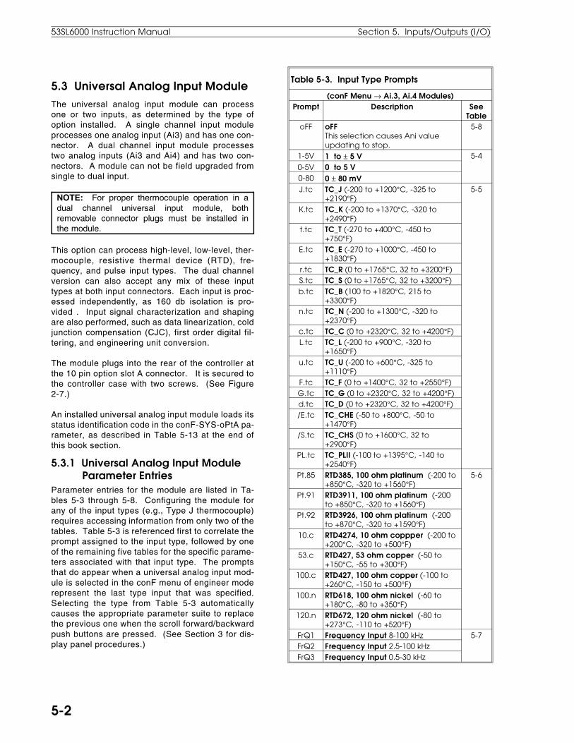
5.3 Universal Analog Input ModuleThe universal analog input module can processone or two inputs, as determined by the type ofoption installed. A single channel input moduleprocesses one analog input (Ai3) and has one con-nector. A dual channel input module processestwo analog inputs (Ai3 and Ai4) and has two con-nectors. A module can not be field upgraded fromsingle to dual input.
NOTE: For proper thermocouple operation in adual channel universal input module, bothremovable connector plugs must be installed inthe module.
This option can process high-level, low-level, ther-mocouple, resistive thermal device (RTD), fre-quency, and pulse input types. The dual channelversion can also accept any mix of these inputtypes at both input connectors. Each input is proc-essed independently, as 160 db isolation is pro-vided . Input signal characterization and shapingare also performed, such as data linearization, coldjunction compensation (CJC), first order digital fil-tering, and engineering unit conversion.
The module plugs into the rear of the controller atthe 10 pin option slot A connector. It is secured tothe controller case with two screws. (See Figure2-7.)
An installed universal analog input module loads itsstatus identification code in the conF-SYS-oPtA pa-rameter, as described in Table 5-13 at the end ofthis book section.
5.3.1 Universal Analog Input Module Parameter EntriesParameter entries for the module are listed in Ta-bles 5-3 through 5-8. Configuring the module forany of the input types (e.g., Type J thermocouple)requires accessing information from only two of thetables. Table 5-3 is referenced first to correlate theprompt assigned to the input type, followed by oneof the remaining five tables for the specific parame-ters associated with that input type. The promptsthat do appear when a universal analog input mod-ule is selected in the conF menu of engineer moderepresent the last type input that was specified.Selecting the type from Table 5-3 automaticallycauses the appropriate parameter suite to replacethe previous one when the scroll forward/backwardpush buttons are pressed. (See Section 3 for dis-play panel procedures.)
Table 5-3. Input Type Prompts
(conF Menu → Ai.3, Ai.4 Modules)Prompt Description See
TableoFF oFF
This selection causes Ani valueupdating to stop.
5-8
1-5V 1 to ± 5 V 5-4
0-5V 0 to 5 V0-80 0 ± 80 mVJ.tc TC_J (-200 to +1200°C, -325 to
+2190°F)5-5
K.tc TC_K (-200 to +1370°C, -320 to+2490°F)
t.tc TC_T (-270 to +400°C, -450 to+750°F)
E.tc TC_E (-270 to +1000°C, -450 to+1830°F)
r.tc TC_R (0 to +1765°C, 32 to +3200°F)S.tc TC_S (0 to +1765°C, 32 to +3200°F)b.tc TC_B (100 to +1820°C, 215 to
+3300°F)n.tc TC_N (-200 to +1300°C, -320 to
+2370°F)c.tc TC_C (0 to +2320°C, 32 to +4200°F)L.tc TC_L (-200 to +900°C, -320 to
+1650°F)u.tc TC_U (-200 to +600°C, -325 to
+1110°F)F.tc TC_F (0 to +1400°C, 32 to +2550°F)G.tc TC_G (0 to +2320°C, 32 to +4200°F)d.tc TC_D (0 to +2320°C, 32 to +4200°F)/E.tc TC_CHE (-50 to +800°C, -50 to
+1470°F)/S.tc TC_CHS (0 to +1600°C, 32 to
+2900°F)PL.tc TC_PLII (-100 to +1395°C, -140 to
+2540°F)Pt.85 RTD385, 100 ohm platinum (-200 to
+850°C, -320 to +1560°F)5-6
Pt.91 RTD3911, 100 ohm platinum (-200to +850°C, -320 to +1560°F)
Pt.92 RTD3926, 100 ohm platinum (-200to +870°C, -320 to +1590°F)
10.c RTD4274, 10 ohm coppper (-200 to+200°C, -320 to +500°F)
53.c RTD427, 53 ohm copper (-50 to+150°C, -55 to +300°F)
100.c RTD427, 100 ohm copper (-100 to+260°C, -150 to +500°F)
100.n RTD618, 100 ohm nickel (-60 to+180°C, -80 to +350°F)
120.n RTD672, 120 ohm nickel (-80 to+273°C, -110 to +520°F)
FrQ1 Frequency Input 8-100 kHz 5-7FrQ2 Frequency Input 2.5-100 kHzFrQ3 Frequency Input 0.5-30 kHz
53SL6000 Instruction Manual Section 5. Inputs/Outputs (I/O)
5-2
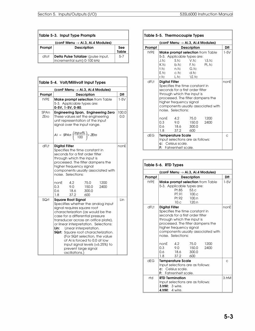
Table 5-3. Input Type Prompts
(conF Menu → Ai.3, Ai.4 Modules)Prompt Description See
Tabledtot Delta Pulse Totalizer (pulse input,
incremental sum) 0-100 kHz5-7
Table 5-4. Volt/Millivolt Input Types
(conF Menu → Ai.3, Ai.4 Modules)Prompt Description Dft
tYPE Make prompt selection from Table5-3. Applicable types are:0-5V, 1-5V, 0-80.
1-5V
SPAnZEro
Engineering Span, Engineering ZeroThese values set the engineeringunit representation of the inputsignal over the input range.
Ai = SPAn
input%100
+ ZEro
100.00.0
dFLt Digital FilterSpecifies the time constant inseconds for a first order filterthrough which the input isprocessed. The filter dampens thehigher frequency signalcomponents usually associated withnoise. Selections:
nonE 4.2 75.0 12000.3 9.0 150.0 24000.6 18.6 300.01.8 37.2 600
nonE
SQrt Square Root SignalSpeciifies whether the analog inputsignal requires square rootcharacterization (as would be thecase for a differential pressuretransducer across an orifice plate),or linear interpretation. Selections:Lin: Linear interpretation.SQrt: Square root characterization. (For SQrt selection, the value of Ai is forced to 0.0 at low input signal levels [<6.25%] to prevent large signal oscillations.)
Lin
Table 5-5. Thermocouple Types
(conF Menu → Ai.3, Ai.4 Modules)Prompt Description Dft
tYPE Make prompt selection from Table5-3. Applicable types are:J.tc S.tc V.tc \S.tcK.tc b.tc F.tc PL.tct.tc n.tc G.tcE.tc c.tc d.tcr.tc L.tc \E.tc
1-5V
dFLt Digital FilterSpecifies the time constant inseconds for a first order filterthrough which the input isprocessed. The filter dampens thehigher frequency signalcomponents usually associated withnoise. Selections:
nonE 4.2 75.0 12000.3 9.0 150.0 24000.6 18.6 300.01.8 37.2 600
nonE
dEG Temperature ScaleInput selections are as follows:c: Celsius scale.F: Fahrenheit scale.
c
Table 5-6. RTD Types
(conF Menu → Ai.3, Ai.4 Modules)Prompt Description Dft
tYPE Make prompt selection from Table5-3. Applicable types are:
Pt.85 53.cPT.91 100.cPt.92 100.n10.c 120.n
1-5V
dFLt Digital FilterSpecifies the time constant inseconds for a first order filterthrough which the input isprocessed. The filter dampens thehigher frequency signalcomponents usually associated withnoise. Selections:
nonE 4.2 75.0 12000.3 9.0 150.0 24000.6 18.6 300.01.8 37.2 600
nonE
dEG Temperature ScaleInput selections are as follows:c: Celsius scale.F: Fahrenheit scale.
c
rtd RTD TerminationInput selections are as follows:3.trM: 3 wire.4.trM: 4 wire.
3.trM
Section 5. Inputs/Outputs (I/O) 53SL6000 Instruction Manual
5-3
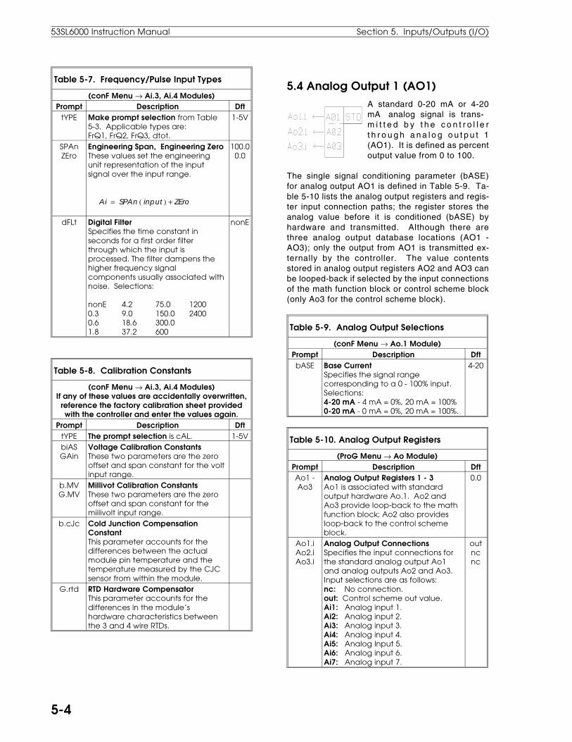
Table 5-7. Frequency/Pulse Input Types
(conF Menu → Ai.3, Ai.4 Modules)Prompt Description Dft
tYPE Make prompt selection from Table5-3. Applicable types are:FrQ1, FrQ2, FrQ3, dtot.
1-5V
SPAnZEro
Engineering Span, Engineering ZeroThese values set the engineeringunit representation of the inputsignal over the input range.
Ai = SPAn ( input ) + ZEro
100.00.0
dFLt Digital FilterSpecifies the time constant inseconds for a first order filterthrough which the input isprocessed. The filter dampens thehigher frequency signalcomponents usually associated withnoise. Selections:
nonE 4.2 75.0 12000.3 9.0 150.0 24000.6 18.6 300.01.8 37.2 600
nonE
Table 5-8. Calibration Constants
(conF Menu → Ai.3, Ai.4 Modules)If any of these values are accidentally overwritten,
reference the factory calibration sheet providedwith the controller and enter the values again.
Prompt Description DfttYPE The prompt selection is cAL. 1-5VbiASGAin
Voltage Calibration ConstantsThese two parameters are the zerooffset and span constant for the voltinput range.
b.MVG.MV
Millivot Calibration ConstantsThese two parameters are the zerooffset and span constant for themiilivolt input range.
b.cJc Cold Junction CompensationConstantThis parameter accounts for thedifferences between the actualmodule pin temperature and thetemperature measured by the CJCsensor from within the module.
G.rtd RTD Hardware CompensatorThis parameter accounts for thedifferences in the module’shardware characteristics betweenthe 3 and 4 wire RTDs.
5.4 Analog Output 1 (AO1)A standard 0-20 mA or 4-20mA analog signal is trans-m i t t e d b y t h e c o n t r o l l e rt h r o u g h a n a l o g o u t p u t 1(AO1). It is defined as percentoutput value from 0 to 100.
The single signal conditioning parameter (bASE)for analog output AO1 is defined in Table 5-9. Ta-ble 5-10 lists the analog output registers and regis-ter input connection paths; the register stores theanalog value before it is conditioned (bASE) byhardware and transmitted. Although there arethree analog output database locations (AO1 -AO3); only the output from AO1 is transmitted ex-ternally by the controller. The value contentsstored in analog output registers AO2 and AO3 canbe looped-back if selected by the input connectionsof the math function block or control scheme block(only Ao3 for the control scheme block).
Table 5-9. Analog Output Selections
(conF Menu → Ao.1 Module)Prompt Description DftbASE Base Current
Specifies the signal rangecorresponding to a 0 - 100% input.Selections:4-20 mA - 4 mA = 0%, 20 mA = 100%0-20 mA - 0 mA = 0%, 20 mA = 100%.
4-20
Table 5-10. Analog Output Registers
(ProG Menu → Ao Module)Prompt Description DftAo1 -Ao3
Analog Output Registers 1 - 3Ao1 is associated with standardoutput hardware Ao.1. Ao2 andAo3 provide loop-back to the mathfunction block; Ao2 also providesloop-back to the control schemeblock.
0.0
Ao1.iAo2.iAo3.i
Analog Output ConnectionsSpecifies the input connections forthe standard analog output Ao1and analog outputs Ao2 and Ao3.Input selections are as follows:nc: No connection.out: Control scheme out value.Ai1: Analog input 1.Ai2: Analog input 2.Ai3: Analog input 3.Ai4: Analog input 4.Ai5: Analog Input 5.Ai6: Analog input 6.Ai7: Analog input 7.
outncnc
53SL6000 Instruction Manual Section 5. Inputs/Outputs (I/O)
5-4
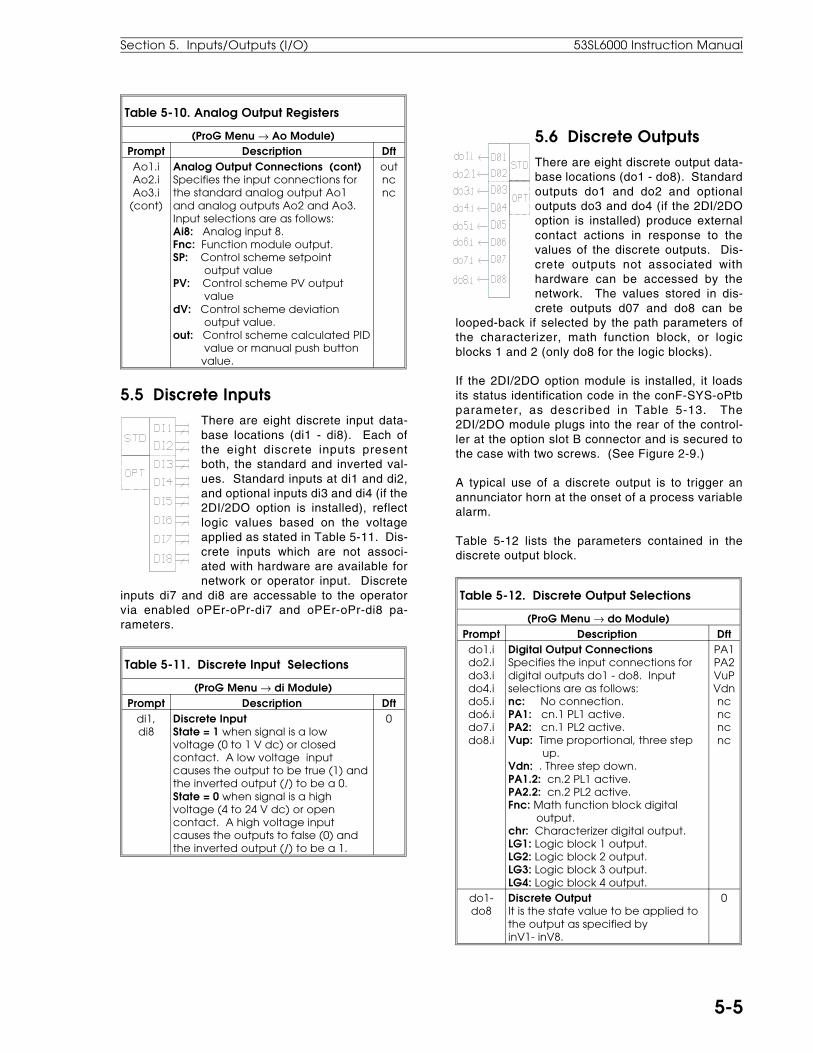
Table 5-10. Analog Output Registers
(ProG Menu → Ao Module)Prompt Description DftAo1.iAo2.iAo3.i
(cont)
Analog Output Connections (cont)Specifies the input connections forthe standard analog output Ao1and analog outputs Ao2 and Ao3.Input selections are as follows:Ai8: Analog input 8.Fnc: Function module output.SP: Control scheme setpoint output valuePV: Control scheme PV output valuedV: Control scheme deviation output value.out: Control scheme calculated PID value or manual push button value.
outncnc
5.5 Discrete InputsThere are eight discrete input data-base locations (di1 - di8). Each ofthe eight discrete inputs presentboth, the standard and inverted val-ues. Standard inputs at di1 and di2,and optional inputs di3 and di4 (if the2DI/2DO option is installed), reflectlogic values based on the voltageapplied as stated in Table 5-11. Dis-crete inputs which are not associ-ated with hardware are available fornetwork or operator input. Discrete
inputs di7 and di8 are accessable to the operatorvia enabled oPEr-oPr-di7 and oPEr-oPr-di8 pa-rameters.
Table 5-11. Discrete Input Selections
(ProG Menu → di Module)Prompt Description Dft
di1,di8
Discrete InputState = 1 when signal is a lowvoltage (0 to 1 V dc) or closedcontact. A low voltage inputcauses the output to be true (1) andthe inverted output (/) to be a 0.State = 0 when signal is a highvoltage (4 to 24 V dc) or opencontact. A high voltage inputcauses the outputs to false (0) andthe inverted output (/) to be a 1.
0
5.6 Discrete OutputsThere are eight discrete output data-base locations (do1 - do8). Standardoutputs do1 and do2 and optionaloutputs do3 and do4 (if the 2DI/2DOoption is installed) produce externalcontact actions in response to thevalues of the discrete outputs. Dis-crete outputs not associated withhardware can be accessed by thenetwork. The values stored in dis-crete outputs d07 and do8 can be
looped-back if selected by the path parameters ofthe characterizer, math function block, or logicblocks 1 and 2 (only do8 for the logic blocks).
If the 2DI/2DO option module is installed, it loadsits status identification code in the conF-SYS-oPtbparameter, as described in Table 5-13. The2DI/2DO module plugs into the rear of the control-ler at the option slot B connector and is secured tothe case with two screws. (See Figure 2-9.)
A typical use of a discrete output is to trigger anannunciator horn at the onset of a process variablealarm.
Table 5-12 lists the parameters contained in thediscrete output block.
Table 5-12. Discrete Output Selections
(ProG Menu → do Module)Prompt Description Dftdo1.ido2.ido3.ido4.ido5.ido6.ido7.ido8.i
Digital Output ConnectionsSpecifies the input connections fordigital outputs do1 - do8. Inputselections are as follows:nc: No connection.PA1: cn.1 PL1 active.PA2: cn.1 PL2 active.Vup: Time proportional, three step up.Vdn: . Three step down.PA1.2: cn.2 PL1 active.PA2.2: cn.2 PL2 active.Fnc: Math function block digital output.chr: Characterizer digital output.LG1: Logic block 1 output.LG2: Logic block 2 output.LG3: Logic block 3 output.LG4: Logic block 4 output.
PA1PA2VuPVdnncncncnc
do1-do8
Discrete OutputIt is the state value to be applied tothe output as specified by inV1- inV8.
0
Section 5. Inputs/Outputs (I/O) 53SL6000 Instruction Manual
5-5
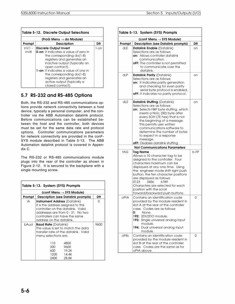
Table 5-12. Discrete Output Selections
(ProG Menu → do Module)Prompt Description DftinV1 -inV8
Discrete Output Invert0-on: it indicates a value of zero in the corresponding do(1-8) registers and generates an inactive output (typically an open contact).1-on: it indicates a value of one in the corresponding do(1-8) registers and generates an active output (typically a closed contact).
1-on
5.7 RS-232 and RS-485 OptionsBoth, the RS-232 and RS-485 communications op-tions provide network connectivity between a hostdevice, typically a personal computer, and the con-troller via the ABB Automation datalink protocol.Before communications can be established be-tween the host and the controller, both devicesmust be set for the same data rate and protocoloptions. Controller communications parametersfor network connectivity are provided in the conF-SYS module described in Table 5-13. The ABBAutomation datalink protocol is covered in Appen-dix C.
The RS-232 or RS-485 communications moduleplugs into the rear of the controller as shown inFigure 2-12. It is secured to the backplane with asingle mounting screw.
Table 5-13. System (SYS) Prompts
(conF Menu → SYS Module)Prompt Description (see Datalink prompts) Dft
iA Instrument Addrsss (Datalink)It is the address assigned to thiscontroller on the datalink. Validaddresses are from 0 - 31. No twocontrollers can have the sameaddress on the datalink.
0
bAud Baud Rate (Datalink)This value is set to match the datatransfer rate of the datalink. Validmenu selections are:
110 4800300 9600600 19.2K1200 14.4K2400 28.8K
9600
Table 5-13. System (SYS) Prompts
(conF Menu → SYS Module)Prompt Description (see Datalink prompts) Dft
dLE Datalink Enable (Datalink)Selections are as follows:on: Allows controller datalink communication.oFF: The controller is not permitted to communicate over the datalink.
on
dLP Datalink Parity (Datalink)Selections are as follows:on: It indicates parity generation and checking for even parity serial byte protocol is enabled.oFF: It indicates no parity protocol.
on
dLS Datalink Stuffing (Datalink)Selections are as follows:on: Selects F&P byte stuffing, which inserts a NULL (00) byte after every SOH (7E hex) that is not the beginning of a message. This permits user written communications software to determine the number of bytes to expect in a response message.oFF: Disables datalink stuffing.
on
Not Communications ParameterstAG Tag Name
Allows a 10 character tag to beassigned to the controller. Fourcharacters maximum can bedisplayed at any one time. Usingthe engineer mode shift right pushbutton, the ten character positionsare displayed as follows:0123 3456 6789Characters are selected for eachposition with the scrollforward/backward push buttons.
b-FP
oPtA Contains an identification codeprovided by the module resident inslot A at the rear of the controllercase. Codes are as follows:0: None.192: 2DI/2DO module.193: Single universal analog input module.194: Dual universal analog input module.
0
oPtb Contains an identification codeprovided by the module resident inslot B at the rear of the controllercase. Codes are the same as foroPtA above.
0
53SL6000 Instruction Manual Section 5. Inputs/Outputs (I/O)
5-6

6.1 Section OverviewSignal modification includes the altering, adjusting,selecting, or limiting of the analog input signal val-ues and digital input values. Modification affectsthe numeric value and not the electrical charac-terisitcs, which are conditioned prior to beingloaded into the analog input registers or digital reg-ister.
Signal modifications are performed by the charac-terizer, the math function block, and/or the digitallogic blocks. These elements are shown in thedetailed controller block diagram, illustrated in Fig-ure 4-2.
6.2 Characterizer As shown below, the characterizer is depicted as afive pin plugable module. As such, it can be desig-nated with its chr.A path selection parameters tointercept and act upon any one of the four functiongenerator analog inputs (Fnc.A - Fnc.d), or anyone of the control scheme’s six analog inputs (cS.A- cS.F). Two additional digital inputs, selectorschr.b and chr.c, are used in the characterizer toactivate or trigger actions based on logic values.Two outputs, one analog and the other digital, pro-duce values based on the mode of operation se-lected by the chr.M parameter and the K1-K26constants.
Table 6-1 is a summary of the connection parame-ters and the assigned applications for constantsK1-K26 by operating mode. Detailed descriptionsof the characterizer operating modes (third orderpolynomial, linear segments mode, setpoint pro-grammer, and digital-to-analog converter) are pro-vided in the sections that follow.
Table 6-1. Characterizer Parameters
(ProG Menu → chr Module)Prompt Description Dftchr.M Characterizer Mode Select
This parameter is used to select howan analog input is characterizedbefore it is passed-on to the mathfunction block for further augmentingor the control scheme. Characterizermode selections are as follows:oFF: No characterization performed.3SEG: Third order polynomial.LSEG: Linear segments mode.PGrM: Setpoint programmer.dtoA: Digital-to-analog conversion.
oFF
chr.A Characterizer Position SelectSpecifies the characterizerconnection point at the mathfunction block or control scheme.Selections are as follows:oFF: The characterizer is not used.Fnc.A: Function module A input.Fnc.b: Function module B input.Fnc.c: Function module C input.Fnc.d: Function module D input.cS.A: Control scheme A input.cS.b: Control scheme B input.cS.c: Control scheme C input.cS.d: Control scheme D input.cS.E: Control scheme E input.cS.F: Control scheme F input.
oFF
chr.bchr.c
Characterizer b and c InputsSpecifies connections to thecharacterizer b and c inputs.Selections are as follows:(1): Logical one input.(0): Logical zero input.di1: Discrete input 1 logic value./di1: Inverted di1 logic value.di2: Discrete input 2 logic value./di2: Inverted di2 logic value.di3: Discrete input 3 logic value./di3: Inverted di3 logic value.di4: Discrete input 4 logic value./di4: Inverted di4 logic value.di5: Discrete input 5 logic value./di5: Inverted di5 logic value.di6: Discrete input 6 logic value./di6: Inverted di6 logic value.di7: Discrete input 7 logic value./di7: Inverted di7 logic value.di8: Discrete input 8 logic value./di8: Inverted di8 logic value.do7: Loop-back do7 register value./d07: Inverted loop-back do7 register value.d08: Loop-back do8 register value./d08: Inverted loop-back do8 register value.
(1)(1)
6.0 Signal Value Modification
Section 6. Signal Value Modification 53SL6000 Instruction Bulletin
6-1

Table 6-1. Characterizer Parameters
(ProG Menu → chr Module)Prompt Description Dft
K01 -K26
Assignments for K01 through K26 forthe three segment (3SEG)characterizer, linear segment (LSEG)characterizer, the setpointprogrammer (PGrM), and the digital-to-analog converter (DtoA) are asfollows
3SEG (executes 5 third orderpolynomials):K01 - K06: Six endpoints that partition the 5 segments.K07 - K10: Segment 1 (equation 1) coefficients.K11 - K14: Segment 2 (equation 2) coefficients.K15 - K18: Segment 3 (equation 3) coefficients.K19 - K22: Segment 4 (equation 4) coefficients.K23 - K26: Segment 5 (equation 5) coefficients.
LSEG (13 ordered pairs for 12segments. Each input value mustbe greater than the previous one):K01 - K13: input coordinates.K14 - K26: output coordinates.Ordered segment pairs are K01, K14;K02, K15; etc.
PGrM:K01 - K13: Entered time intervals in whole seconds. Negative numbers not permitted.K14 - K26: Target analog output from characterizer (per step).
DtoA:K1: B input ramp rate (up).K2: C input ramp rate (down).K3: Lower output limit.K4: Upper output limit.
0.0
6.2.1. 3SEG ModeThe third order polynomial segment characterizerallows the user to define five adjacent segments.Each segment has an independent third order poly-nomial defining the relationship between the A in-put value and the analog output value. Wheneverthe A input value does not fall within any of the fivesegments, a logical 1 value is produced at the char-acterizer’s digital output; otherwise, a logical 0value is present at the digital output. The charac-terizer analog output value is forced to reflect thevalue related to the nearest defined segment when-ever the A input is outside all defined segments.
The five segments are defined by the constants K1through K6. The values assigned to these con-stants must be monotonically increasing, goingfrom K1 to K6, to ensure the segments are adja-cent. Constants K7 through K26 are divided intofive groups, each with four constants. The groupacts as a set of coefficients for an individual seg-ment’s polynomial as given by the equation andtable below:
Output = WA 3 + XA 2 + YA + Z
Equation Segment W X Y Z1 K1-K2 K7 K8 K9 K102 K2-K3 K11 K12 K13 K143 K3-K4 K15 K16 K17 K184 K4-K5 K19 K20 K21 K225 K5-K6 K23 K24 K25 K26
This characterizer mode provides the capability tol inearize complex curves (e.g., thermocouplecurves). A linearization example of an E-type ther-mocouple (operating range -115° to 1000° C) withthe characterizer A input provided in millivolts is asfollows:
Eq. Segment W X Y Z1 K1: -5.90
K2: 0.0K7:0.03947
K8:0.1575
K9:17.20
K10:0.04199
2 K2: 0.0K3: 13.42
K11:0.004269
K12:0.2143
K13:17.01
K14:0.02144
3 K3: 7.0 K4: 36.99
K15:0.0007227
K16:0.0769
K17:15.12
K18:9.264
4 K4: 36.99K5: 61.02
K19:0.0002274
K20:0.02488
K21:13.26
K22:32.13
5 K5: 61.02K6: 76.40
K23:0.0001247
K24:0.004976
K25:11.95
K26:60.8
Note: many of the values shown in this examplecan not be entered directly at the front displaypanel due to the limited size of the data entry dis-play; however, the values given are easily loadablevia the communications network datalink interface(requires the RS-485 option module).
6.2.2 LSEG ModeThe linear segment characterizer allows the user todefine a relationship between the A input and theanalog output value via a piecewise linear approxi-mation. The approximation is made up of twelveadjacent line segments. Each line segment end-points are defined by two pairs of coordinates, re-quir ing thirteen coordinate pairs in all . Thecoordinate values are stored in characterizer con-stants K1-K26.
Micro-DCI 53SL6000 Controller
6-2

To ensure the piecewise approximation specifies arealizable function, the values for the coordinateinputs, which are stored in characterizer constantsK1 through K13, must be monotonically increasing(each coordinate value is larger than the precedingone). There is no such dependency for the outputcoordinate values K14 through K26.
Whenever the A input value falls outside all of theline segments, the characterizer’s digital outputvalue is set to a logical 1; otherwise, the digitaloutput value is always a logical 0. The correspond-ing output value for an A input outside all of the linesegments can be determined by extending eitherthe first or the last segment, as required.
An example of coordinate pair constant assign-ments is illustrated in the following table and figure:
Pair A Input Analog Output1 K1 = 0.0 K14 = 0.02 K2 = 1.0 K15 = 1.03 K3 = 2.0 K16 = 4.04 K4 = 3.0 K17 = 9.05 K5 = 4.0 K18 = 16.06 K6 = 5.0 K19 = 25.07 K7 = 6.0 K20 = 36.08 K8 = 7.0 K21 = 49.09 K9 = 8.0 K22 = 64.0
10 K10 = 9.0 K23 = 81.011 K11 = 10.0 K24 = 100.012 K12 = 11.0 K25 = 121.013 K13 = 12.0 K26 = 144.0
6.2.3 PrGM ModeThe characterizer programmer mode allows theuser to define an analog output which depends onthe oPEr-StEP parameter value, the elapsed timesince the current step was entered, the target valueof the StEP, and the target value of the previousStEP. A typical application for programmer modeis a setpoint ramp and hold sequence generator.
Thirteen steps can be defined with the charac-terizer constants K1 through K26. Constants K1through K13 are configured with the time interval(0-9999 seconds) required for the target value tobe reached at each step and constants K14through K26 are configured with the target analogoutput values for each of the steps. During eachstep the characterizer’s analog output ramps fromthe target value of the previous step to the targetvalue of the current step. The current step targetvalue is reached just as the time interval for thatstep expires. One exception is the first step, whichhas no previous target, and therefore, outputs thetarget value for the entire interval.
The characterizer’s digital output is a logical zerovalue throughout the execution of the step se-quence. At completion of the last (thirteenth) step,the digital value is set to a logical one to indicatecompletion of the sequence.
The A input is not used in this mode. The twodigital inputs, B and C, are used as follows:
• The C input forces both the StEP and intervaltimer values to zero whenever it is a logicalzero value.
• The B input value specifies whether the inter-val timer is running (B input = logical 1) orstopped (B input = logical 0).
The parameter oPEr-StEP allows the operator toview the current step value and to manually ad-vance or return to any step in the sequence.
A setpoint programmer ramp and hold sequence,followed by a summary table and illustration, fol-lows:
• Load K1-K13 with the time duration intervalsand load K14-K26 with the desired setpointvalue at each interval.
• Access chr.M of the chr module and set it toPGrM.
• Access chr.A of the chr module and ensure it isset to cS.b.
Section 6. Signal Value Modification 53SL6000 Instruction Bulletin
6-3

• When engineer mode is exited and run is se-lected, the setpoint will move to the assignedvalue for the duration of its corresponding timeinterval.
• To view the stepped sequence manually, ac-cess the StEP parameter in the oPEr menu inengineer mode.
• After StEP is selected, the current time intervalnumber flashes in the red dro.
• Use the scroll forward/backward push buttonsto select a new time interval.
• After pressing the enter push button, the set-point will jump to a new value corresponding tothe time interval number entered.
Time Interval Time Duration Setpoint Value1 1.0 52.02 2.0 70.03 1.0 70.04 3.0 50.05 1.0 30.06 3.0 100.07 2.0 90.08 2.0 90.09 3.0 65.0
10 2.0 35.011 3.0 25.012 2.0 25.013 4.0 10.0
6.2.4 DtoA ModeIn digital-to-analog mode, the logical values of digi-tal inputs B and C are converted into a repre-sentative analog output value. The analog value isbased on the duration of a logical one value oneither input and constants K1 through K4.
When the B input value is a logical one, the charac-terizer’s analog output value will ramp up at therate set by K1 in units/second. When the C inputvalue is a logical one, the characterizer’s analog
output value will ramp down at the rate set by K2 inunits/second. The analog output value is kept be-tween the lower and upper limits set in K3 and K4respectively. Whenever the analog output value isbeing limited, the digital output will be a logical one;otherwise, it is a logical zero.
The figure below illustrates the relationship be-tween the digital inputs and resulting analog out-put. The logic output limiting indicator is alsoshown in the figure.
6.3 Math Function BlockThe math function block (shown below) allows theuser to choose one of nine algebraic equations withthe ProG-Fnc-Fnc.M parameter. These equationsare provided to meet a wide range of applicationrequirements. Depending on the equation se-lected, up to four analog inputs (A - D), two digitalinputs (E and F), and six constants (K1 - K6) areused to generate the analog and digital outputs.The path connection parameters (Fnc.A - Fnc.F)allow the user to choose inputs from a variety ofanalog and digital sources, and align them as re-quired in the fixed equation positions to obtain thedesired outputs.
Table 6-2 summarizes the ProG-Fnc module pa-rameter selections for the math function block. Theequations with brief descriptions follow the table.
Micro-DCI 53SL6000 Controller
6-4
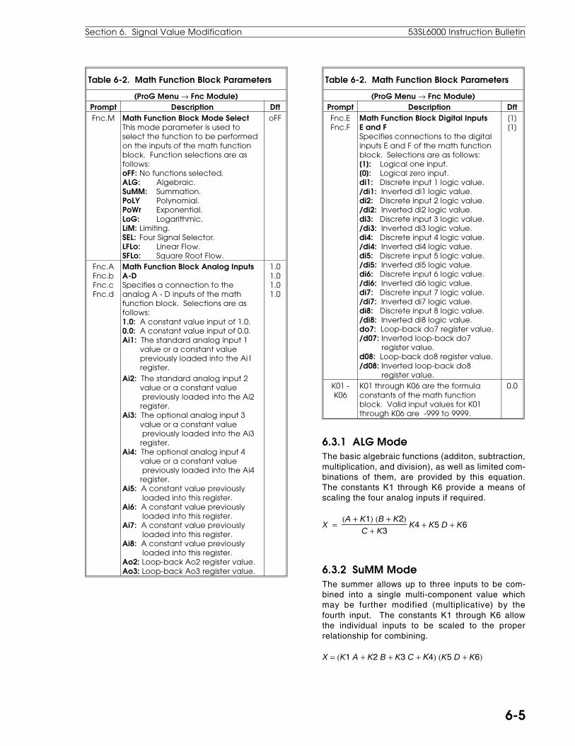
Table 6-2. Math Function Block Parameters
(ProG Menu → Fnc Module)Prompt Description DftFnc.M Math Function Block Mode Select
This mode parameter is used toselect the function to be performedon the inputs of the math functionblock. Function selections are asfollows:oFF: No functions selected.ALG: Algebraic.SuMM: Summation.PoLY Polynomial.PoWr Exponential.LoG: Logarithmic.LiM: Limiting.SEL: Four Signal Selector.LFLo: Linear Flow.SFLo: Square Root Flow.
oFF
Fnc.AFnc.bFnc.cFnc.d
Math Function Block Analog InputsA-D Specifies a connection to theanalog A - D inputs of the mathfunction block. Selections are asfollows:1.0: A constant value input of 1.0.0.0: A constant value input of 0.0.Ai1: The standard analog input 1 value or a constant value previously loaded into the Ai1 register.
1.01.01.01.0
Ai2: The standard analog input 2 value or a constant value previously loaded into the Ai2 register.Ai3: The optional analog input 3 value or a constant value previously loaded into the Ai3 register.Ai4: The optional analog input 4 value or a constant value previously loaded into the Ai4 register.Ai5: A constant value previously loaded into this register.Ai6: A constant value previously loaded into this register.Ai7: A constant value previously loaded into this register.Ai8: A constant value previously loaded into this register.Ao2: Loop-back Ao2 register value.Ao3: Loop-back Ao3 register value.
Table 6-2. Math Function Block Parameters
(ProG Menu → Fnc Module)Prompt Description DftFnc.EFnc.F
Math Function Block Digital InputsE and FSpecifies connections to the digitalinputs E and F of the math functionblock. Selections are as follows:[1]: Logical one input.[0]: Logical zero input.di1: Discrete input 1 logic value./di1: Inverted di1 logic value.di2: Discrete input 2 logic value./di2: Inverted di2 logic value.di3: Discrete input 3 logic value./di3: Inverted di3 logic value.di4: Discrete input 4 logic value./di4: Inverted di4 logic value.di5: Discrete input 5 logic value./di5: Inverted di5 logic value.di6: Discrete input 6 logic value./di6: Inverted di6 logic value.di7: Discrete input 7 logic value./di7: Inverted di7 logic value.di8: Discrete input 8 logic value./di8: Inverted di8 logic value.do7: Loop-back do7 register value./d07: Inverted loop-back do7 register value.d08: Loop-back do8 register value./d08: Inverted loop-back do8 register value.
[1][1]
K01 -K06
K01 through K06 are the formulaconstants of the math functionblock. Valid input values for K01through K06 are -999 to 9999.
0.0
6.3.1 ALG ModeThe basic algebraic functions (additon, subtraction,multiplication, and division), as well as limited com-binations of them, are provided by this equation.The constants K1 through K6 provide a means ofscaling the four analog inputs if required.
X = (A + K1) (B + K2)
C + K3 K4 + K5 D + K6
6.3.2 SuMM ModeThe summer allows up to three inputs to be com-bined into a single multi-component value whichmay be further modified (multiplicative) by thefourth input. The constants K1 through K6 allowthe individual inputs to be scaled to the properrelationship for combining.
X = (K1 A + K2 B + K3 C + K4) (K5 D + K6)
Section 6. Signal Value Modification 53SL6000 Instruction Bulletin
6-5

6.3.3 PoLY ModeThis is a third order polynomial equation which op-erates on an algebraic combination of the four ana-log inputs. The constants K1 through K4 are thecoefficients for the equation. The constants K5and K6 allow for some limited scaling of the fouranalog inputs.
X = K4
(AB + K5)C + K6
+ D
3 + K3
(AB + K5)C + K6
+ D
2 + K2
(AB + K5)C + K6
+ D + K1
6.3.4 PoWr ModeThis mode provides a general purpose exponential(power) equation with the four analog inputs as-signed in the exponent, base, multiplier, and bias.The constants K1 through K6 provide scaling for allfour except the bias term.
X = K5C + K6 [ K1A + K2](K3B + K4)
+ D
An important use of the exponential equation iscalculating flow values using weirs and Parshallflumes as measuring elements. The table belowgives the required assignments for three types ofweirs: rectangular, cipolletti, and triangular basedon the weirs dimensions (Length - feet, height -inches, and x - degrees). Analog output is in gal-lons per minute (gpm).
Power Equation Constants by Weir TypeConstant Rectangular Cipolletti Triangular
Fnc.A h h hFnc.b 0 0 0Fnc.c h 0 0Fnc.d 0 0 0K1 1 1 1K2 0 0 0K3 0 0 0K4 1.5 1.5 2.47K5 -0.6 0 0K6 3L 3.037L see K6
belowK6 for triangular weirs is as follows:
K6 = 2.42.9 [ tan ( x2
) ] 0.992
6.3.5 LoG ModeThe logarithm equation produces a base 2 logarith-mic value of the algebraic function of the four ana-log inputs. The constants K1 through K5 providescaling for the input values. Constant K5 is a mul-tiplier which can be used to convert the base of thelogarithm. For example:
Log 10 (x) = 0.301 Log 2 (x)
Log e (x) = 0.6932 Log 2 (x)
X = K5 Log 2
(A + K1) (B + K2)C + K3
K4 + D + K6
6.3.6 LiM ModeThe limiter generates both an analog and a digitaloutput value. The analog output reflects the scaledA input as long as it does not exceed the scaled Binput (upper limit) or fall below the scaled C input(lower limit). If either is exceeded, the digital out-put will be a logical one value; otherwise, it is alogical 0 value.
if K1A + K2 ≥ K3B = K4 then X = K3B + K4, Y = 1
else if K5C + K6 ≥ K1A + K2 then X = K5C + K6, Y = 1
else X = A Y = 0
Micro-DCI 53SL6000 Controller
6-6

6.3.7 SEL ModeThe selector allows one of four analog input valuesto be passed to the analog output based on thevalues of the two digital inputs (E and F). Three ofthe analog inputs (B, C, and D) can be scaled bythe constants K1 through K6. The switching dia-gram below the equation shows how the digitalinputs control the value passed to the analog out-put.
if E = 1 and F = 1, then X = K5D + K6
if E = 1 and F = 0, then X = K3C + K4
if E = 0 and F = 1, then X = K1B + K2
if E = 0 F = 0, then X = A
6.3.8 Gas Flow Compensation EquationsPressure and temperature compensated gas flowequations for both linear and square root flow ele-ments are provided to compute the mass flow or"standard volume" flow of a gas. The equationshandle both perfect and imperfect gases. Threeinputs representing A - flow (differential pressure),B - absolute pressure, and C - absolute tempera-ture are converted to a flow output signal based ona set on parameters K1 through K6.
Imperfect Gases in Operating ZoneK1 Overall meter coefficientK2 Slope of Y factor line (negative)K3 Coefficient in density equationK4 Pressure bias in density equationK5 Temperature bias in density equationK6 Density bias in density equation
K3-K6 Inputs for Gas that Behaves asPerfect Gas in Operating Zone
K3 Molecular weight/Universal GasConstant, R
K4 0K5 460° R or 273° KK6 0
K2 Input if Acoustic Ratio is Very Low (Y = 1.0)
K2 0
6.3.8.1 Linear Gas Flow Compensation (LFLo) Equation
X = K1A [ K3 B − K4C + K5
+ K6]A is actual CFM volumetric flowB is absolute pressureC is temperature (in R or K)
6.3.8.2 Square Root Gas Flow Compensation (SFLo) Equation
X = K1 [ 1 − K2 AB] √A [ K3
B − K4C + K5
+ K6 ]A is measured differential pressureB is absolute pressureC is temperature (in R or K)
6.4 Logic Blocks 1, 2, 3, and 4As shown in the figures below, each logic block1,2,3, and 4 can perform a selected mode of opera-tion on two input variables A and B to produce anoutput at LG(1-4). Inputs A and B, as well as theoutput, are all logic values (0/1). The applicablemodes of operation and the selectable inputs for allfour logic blocks are provided in Table 6-3 and theoutputs produced by the various operating modesare summarized in Table 6-4.
Section 6. Signal Value Modification 53SL6000 Instruction Bulletin
6-7
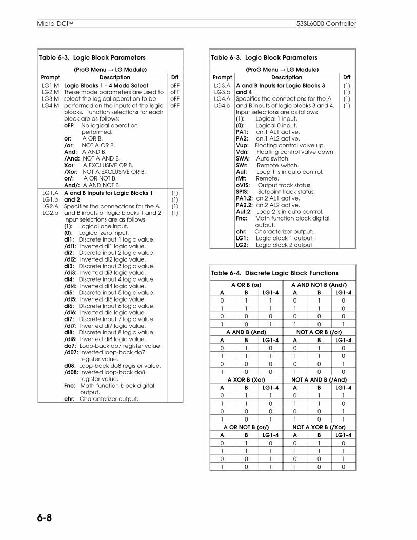
Table 6-3. Logic Block Parameters
(ProG Menu → LG Module)Prompt Description DftLG1.MLG2.MLG3.MLG4.M
Logic Blocks 1 - 4 Mode SelectThese mode parameters are used toselect the logical operation to beperformed on the inputs of the logicblocks. Function selections for eachblock are as follows:oFF: No logical operation performed.or: A OR B./or: NOT A OR B.And: A AND B./And: NOT A AND B.Xor: A EXCLUSIVE OR B./Xor: NOT A EXCLUSIVE OR B.or/: A OR NOT B.And/: A AND NOT B.
oFFoFFoFFoFF
LG1.ALG1.bLG2.ALG2.b
A and B Inputs for Logic Blocks 1and 2Specifies the connections for the Aand B inputs of logic blocks 1 and 2.Input selections are as follows:[1]: Logical one input.[0]: Logical zero input.di1: Discrete input 1 logic value./di1: Inverted di1 logic value.di2: Discrete input 2 logic value./di2: Inverted di2 logic value.di3: Discrete input 3 logic value./di3: Inverted di3 logic value.di4: Discrete input 4 logic value./di4: Inverted di4 logic value.di5: Discrete input 5 logic value./di5: Inverted di5 logic value.di6: Discrete input 6 logic value./di6: Inverted di6 logic value.di7: Discrete input 7 logic value./di7: Inverted di7 logic value.di8: Discrete input 8 logic value./di8: Inverted di8 logic value.do7: Loop-back do7 register value./d07: Inverted loop-back do7 register value.d08: Loop-back do8 register value./d08: Inverted loop-back do8 register value.Fnc: Math function block digital output.chr: Characterizer output.
[1][1][1][1]
Table 6-3. Logic Block Parameters
(ProG Menu → LG Module)Prompt Description DftLG3.ALG3.bLG4.ALG4.b
A and B Inputs for Logic Blocks 3and 4Specifies the connections for the Aand B inputs of logic blocks 3 and 4.Input selections are as follows:[1]: Logical 1 input.[0]: Logical 0 input.PA1: cn.1 AL1 active.PA2: cn.1 AL2 active.Vup: Floating control valve up.Vdn: Floating control valve down.SWA: Auto switch.SWr: Remote switch.Aut: Loop 1 is in auto control.rMt: Remote.oVtS: Output track status.SPtS: Setpoint track status.PA1.2: cn.2 AL1 active.PA2.2: cn.2 AL2 active.Aut.2: Loop 2 is in auto control.Fnc: Math function block digital output.chr: Characterizer output.LG1: Logic block 1 output.LG2: Logic block 2 output.
[1][1][1][1]
Table 6-4. Discrete Logic Block Functions
A OR B (or) A AND NOT B (And/)A B LG1-4 A B LG1-40 1 1 0 1 01 1 1 1 1 00 0 0 0 0 01 0 1 1 0 1
A AND B (And) NOT A OR B (/or)A B LG1-4 A B LG1-40 1 0 0 1 01 1 1 1 1 00 0 0 0 0 11 0 0 1 0 0
A XOR B (Xor) NOT A AND B (/And)A B LG1-4 A B LG1-40 1 1 0 1 11 1 0 1 1 00 0 0 0 0 11 0 1 1 0 1A OR NOT B (or/) NOT A XOR B (/Xor)
A B LG1-4 A B LG1-40 1 0 0 1 01 1 1 1 1 10 0 1 0 0 11 0 1 1 0 0
Micro-DCI 53SL6000 Controller
6-8
7.1 Control Scheme BlockThe control scheme block, which is the primaryfunctional element of the controller, provides thecapability to select and implement any one of fivecontrol schemes. Each control scheme is the basicbuilding block for many control strategies. The fivecontrol schemes are described as follows:
• SnGl - For control strategies requiring singleloop standard PID functional capabilities.
• cASc - For control strategies requiring tightercontrol of processes using dual PID loops in acascade configuration.
• L.LiM - For control strategies with two interde-pendent loops where one of the two variablesmust not exceed a safe low limit.
• h.LiM - For control strategies with two interde-pendent loops where one of the two variablesmust not exceed a safe high limit.
• in .Ld - For appl icat ions that require anauto/manual selector, or a manual loader, or atwo/three variable indicator with process vari-able re-transmission capabilities
When used in conjunction with the path selections,configuration parameters, characterizer block,math function block, discrete logic blocks 1-4, andI/O blocks, the five control schemes are able toaddress most standard control applications. Eachof the control schemes, with the exception of theindicator/loader (in.Ld), have a setpoint generatorwith deviation calculator, a PID algorithm, and anauto/manual output selector. The in.Ld controlscheme does not implement the setpoint generatoror the PID algorithm, as its primary functions aresignal display, selection, signal re-transmission,and manual output control.
Control scheme information presented in this sec-tion covers the cS.A - cS.L input signal selectorsfor each of the control schemes, the controlscheme logic, the three major parts (SP generator,PID, A/M selector) of a control scheme with SnGL,cASc, L.LiM, and h.LiM exceptions noted, and thein.LD control scheme.
Also covered are all control scheme related pa-rameters and input selections.
7.2 Control Scheme InputsThe five control schemes with their inputs are illus-trated in Figure 7-1. In the figure, the L.LiM andh.LiM control schemes are shown in the same illus-tration, as these two control schemes have thesame inputs. Each control module (cn.1, cn.2) isalso identified in the figure by loop number.
The A-F inputs loaded via the cS.A - cS.F inputselectors for all five of the control schemes arededicated to analog signals. These analog signalscan come from the analog inputs or the math func-tion block and may be modified with the charac-terizer block. The h-L inputs loaded via the cS.h -cS.L input selectors are the control signal enablesthat cause the control schemes to perform specificfunctions (e.g., AE for auto enable, RE for remoteenable, etc.). The control signals are digital logicvalues which can come from the discrete inputs,the math function block, or the logic blocks.
7.3 Control Scheme Control SignalsTable 7-1 describes the operations for the logiccontrol signals contained in control modules cn.1and cn.2. These signals are derived from both,digital input logic values and push button. Theycontrol analog signal switches which in turn affectthe operations and thus the outputs of the controlmodules. Also provided, is Figure 7-2, which illus-trates the interrelationships between digital inputs,push buttons entries, control scheme switches, andother control signals. As shown in the figure, thecontrol signal priorities are oVtS having prece-dence over Aut, and SPtS having precedence overrMt. The control signals are depicted in hexagons.Other analog signal switches are controlled by theconF-cn.1(cn.2) module parameters, which are de-picted as circled inputs; and the ProG-cS moduleparameters, which are depicted as diamond inputs.
7.0 Control Scheme Block
Section 7. Control Scheme Block 53SL6000 Instruction Manual
7-1
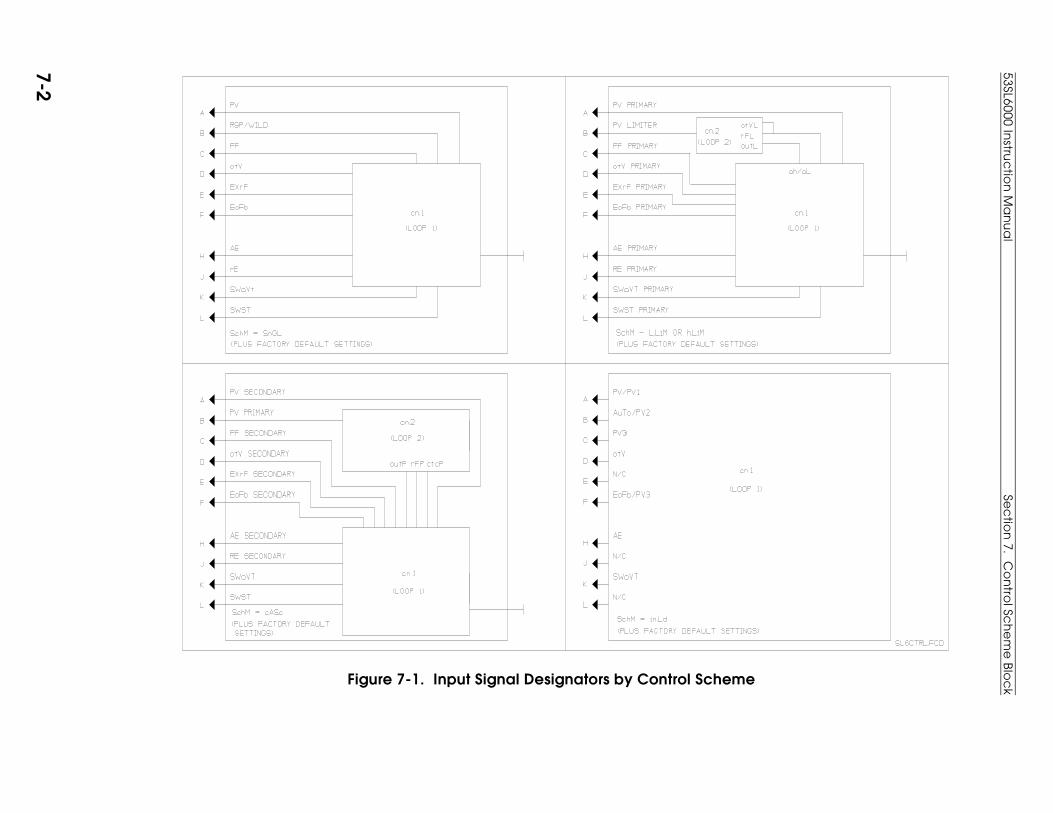
Figure 7-1. Input Signal Designators by Control Scheme
53SL6000 Instru
ctio
n M
an
ua
lSe
ctio
n 7. C
on
trol Sc
he
me
Blo
ck
7-2
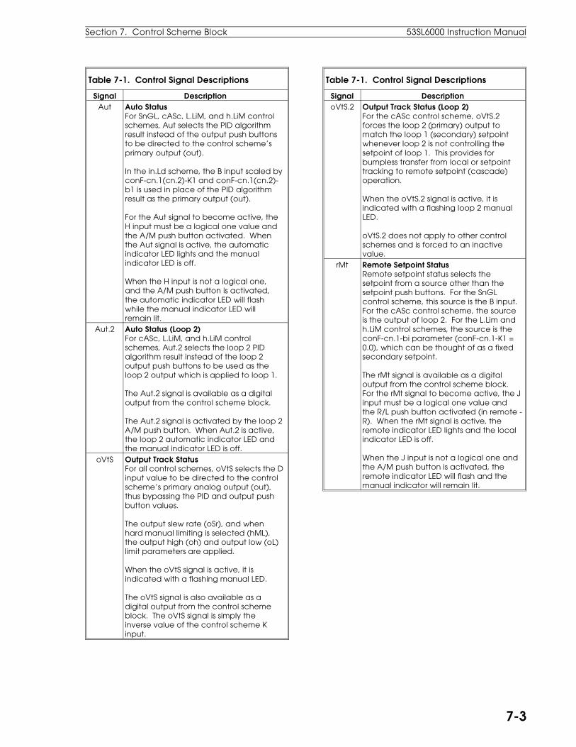
Table 7-1. Control Signal Descriptions
Signal DescriptionAut Auto Status
For SnGL, cASc, L.LiM, and h.LiM controlschemes, Aut selects the PID algorithmresult instead of the output push buttonsto be directed to the control scheme’sprimary output (out).
In the in.Ld scheme, the B input scaled byconF-cn.1(cn.2)-K1 and conF-cn.1(cn.2)-b1 is used in place of the PID algorithmresult as the primary output (out).
For the Aut signal to become active, theH input must be a logical one value andthe A/M push button activated. Whenthe Aut signal is active, the automaticindicator LED lights and the manualindicator LED is off.
When the H input is not a logical one,and the A/M push button is activated,the automatic indicator LED will flashwhile the manual indicator LED willremain lit.
Aut.2 Auto Status (Loop 2)For cASc, L.LiM, and h.LiM controlschemes, Aut.2 selects the loop 2 PIDalgorithm result instead of the loop 2output push buttons to be used as theloop 2 output which is applied to loop 1.
The Aut.2 signal is available as a digitaloutput from the control scheme block.
The Aut.2 signal is activated by the loop 2A/M push button. When Aut.2 is active,the loop 2 automatic indicator LED andthe manual indicator LED is off.
oVtS Output Track StatusFor all control schemes, oVtS selects the Dinput value to be directed to the controlscheme’s primary analog output (out),thus bypassing the PID and output pushbutton values.
The output slew rate (oSr), and whenhard manual limiting is selected (hML),the output high (oh) and output low (oL)limit parameters are applied.
When the oVtS signal is active, it isindicated with a flashing manual LED.
The oVtS signal is also available as adigital output from the control schemeblock. The oVtS signal is simply theinverse value of the control scheme Kinput.
Table 7-1. Control Signal Descriptions
Signal DescriptionoVtS.2 Output Track Status (Loop 2)
For the cASc control scheme, oVtS.2forces the loop 2 (primary) output tomatch the loop 1 (secondary) setpointwhenever loop 2 is not controlling thesetpoint of loop 1. This provides forbumpless transfer from local or setpointtracking to remote setpoint (cascade)operation.
When the oVtS.2 signal is active, it isindicated with a flashing loop 2 manualLED.
oVtS.2 does not apply to other controlschemes and is forced to an inactivevalue.
rMt Remote Setpoint StatusRemote setpoint status selects thesetpoint from a source other than thesetpoint push buttons. For the SnGLcontrol scheme, this source is the B input.For the cASc control scheme, the sourceis the output of loop 2. For the L.Lim andh.LiM control schemes, the source is theconF-cn.1-bi parameter (conF-cn.1-K1 =0.0), which can be thought of as a fixedsecondary setpoint.
The rMt signal is available as a digitaloutput from the control scheme block.For the rMt signal to become active, the Jinput must be a logical one value andthe R/L push button activated (in remote -R). When the rMt signal is active, theremote indicator LED lights and the localindicator LED is off.
When the J input is not a logical one andthe A/M push button is activated, theremote indicator LED will flash and themanual indicator will remain lit.
Section 7. Control Scheme Block 53SL6000 Instruction Manual
7-3

Table 7-1. Control Signal Descriptions
Signal DescriptionSPtS Setpoint Track Status
For the SnGL, cASc, L.LiM, and h.LiMcontrol schemes, SPtS selects the StVvalue to be used for the setpoint, thusbypassing the remote setpoint andsetpoint push button values.
The value of StV follows the A input whenprocess variable tracking (PVt) isselected; otherwise, it is a fixedconfigurable value.
The setpoint slew rate (SSr) and thesetpoint high and low limit (sh, sL)paramerters are applied.
When the SPtS signal is active, it isindicated with a flashing local LED.
The SPtS signal is also available as adigital output from the control schemeblock. The SPtS signal is simply the inversevalue of the L input when there is noprocess variable track.
When process variable tracking isselected, SPtS is active whenever oVtS isactive or when Aut is not active.
SPtS.2 Septoint Track Status (Loop 2)For cASc, L.LiM, and h.LiM controlschemes when process variable tracking(PVt.2) is selected for the primary (cASc)or limiting (L/h.LiM) loop (loop 2), SPtS.2selects the B input as the setpoint valuefor the primary/limiting loop instead ofthe loop 2 setpoint push buttons.
SPtS.2 is simply the inverse of Aut.2 withthe L.Lim and h.LiM control schemes.
For the cASc control scheme, SPtS.2 isactive whenever the primary loop is notcontrolling the setpoint of the secondaryloop (loop 1), or whenever the primaryloop is not in automatic operating mode.
When the SPtS.2 signal is active, it isindicated with a flashing loop 2 local LED.
SPtS.2 does not apply to the SnGL or thein.Ld control schemes or when processvariable tracking (PVt.2) is not active inloop 2, in which case it is forced to aninactive value.
53SL6000 Instruction Manual Section 7. Control Scheme Block
7-4

Figure 7-2. Control Signal Logic Paths
Sec
tion
7. Co
ntro
l Sch
em
e B
loc
k53SL6000 In
struc
tion
Ma
nu
al
7-5

7.4 Signal Paths for the SnGL, cASc, L.LiM, and h.LiM Control SchemesFigure 7-3 is a graphical representation of the con-trol scheme block as it applies to the SnGL, cASc,L.LiM, and h.LiM control schemes. The hexagonsin the figure are the control signal outputs fromFigure 7-2. They enable analog signal switchpaths that affect operation of the control scheme.Other analog signal switches are controlled by theconF-cn.1(cn.2) module parameters, which are de-picted as circled inputs; and the ProG-cS moduleparameters, which are depicted as diamond inputs.
Figure 7-3 contains both, the cn.1 and cn.2 controlloop modules. The upper half of the diagram is forcn.2 and the lower half is for cn.1. Each half con-tains three distinct functional areas:
1. Setpoint Generator with Deviation Calculator(SP-PV) - It controls setpoint selection (localpush buttons, remote setpoint [cn.1 only], orsetpoint tracking) and applies the setpointhigh/low limits and setpoint slew rate. It calcu-lates the deviation (SP-PV) to determine theerror value that is passed on to the PID aftercontrol zone modification. It generates proc-ess or deviation alarms, and also drives thesetpoint display bar, setpoint dro, PV displaybar, and PV dro.
2. PID - It uses the deviation and process vari-able values as determined by direct or reversecontrol action to apply the proportional, inte-gral, and derivative actions; and augments theresult with any additive feed forward (input).The integral term allows both, internal and ex-ternal E input feedback paths. Finally, it ap-plies the output high/low limits to the result.
3. Auto/Manual Output Selector (OUT) - It allowsthe control output (out) to be selected from oneof the three sources: PID result, output pushbuttons, or output tracking (D input). It alsoapplies the output high/low limits when indi-cated by the conF-cn.1(cn.2)-hML parameterto the final result. Both, an analog (out) anddual digital (VuP, Vdn) output are provided.
The cn.1 and cn.2 modules are very similar; how-ever, cn.1 also has the conF-cn.1-SPM (setpointmode) path enable parameter. Its purpose is toselect between the ratio (K-SP) and standard (Std)setpoints.
7.4.1 Setpoint (SP-PV) Paths for the SnGL, cASc, L.LiM, and h.LiM Control SchemesThe control scheme setpoint (SP-PV) paths aredepicted in Figures 7-4 through 7-9. These figuresare partials of Figure 7-3. Unless specifically re-quired by the example (e.g., SPM = K-SP, for theremote ratio setpoint example in Figure 7-6), theparameter path settings are arbitrary (e.g., SPMcan be set for standard [Std] or ratio [K-SP] set-point in the other examples). The control schemesetpoint path figures are as follows:
• Figure 7-4. Common Setpoint Path Logic
• Figure 7-5. Local Standard (Std) Setpoint Path
• Figure 7-6. Remote Ratio Setpoint Path
• Figure 7-7. STV Setpoint Tracking
• Figure 7-8. PVT Setpoint Tracking
• Figure 7-9. cASc Control Scheme Setpoint Path
7.4.2 PID Paths for the SnGL, cASc, L.LiM, and h.LiM Control SchemesThe control scheme PID paths are depicted in Fig-ures 7-10 through 7-12. These figures are partialsof Figure 7-3. Unless specifically required by theexample, the parameter path settings are arbitrary(e.g., rSW can be set for direct [dir] or reverse[rEV]). The control scheme PID path figures areas follows:
• Figure 7-10. Pb, td, and tr PID Paths
• Figure 7-11. Pb, td, tr, and FF PID Paths
• Figure 7-12. Pb, td, tr, and FF PID Paths with EXrF
7.4.3 OUT Paths for the SnGL, cASc, L.LiM, and h.LiM Control SchemesThe control scheme OUT paths are depicted inFigures 7-13 through 7-16. These figures are par-tials of Figure 7-3. Unless specifically required bythe example, the parameter path settings are arbi-trary (e.g., rSV can be set for direct [dir] or reverse[rEV]). The control scheme OUT path figures areas follows:
• Figure 7-13. Output Tracking Path
• Figure 7-14. Auto Output Path
53SL6000 Instruction Manual Section 7. Control Scheme Block
7-6

• Figure 7-15. Manual Output Path
• Figure 7-16. Auto Digital Output Path
7.5 Signal Paths for the in.Ld Control SchemeThe indicator/loader (in.Ld) control scheme pathsare depicted in Figures 7-17 through 7-20. Thehexagons in the figures are the control signal out-puts from Figure 7-2. They enable analog signalswitch paths that affect operation of the controlscheme. Other analog signal switches are con-trolled by the conF-cn.1 module parameters, whichare depicted as circled inputs; and the ProG-cSmodule parameters, which are depicted as dia-mond inputs. Unless specifically required by theexample, the parameter path settings are arbitrary(e.g., rSV can be set for direct [dir] or reverse[rEV]). The in.Ld control scheme path figures areas follows:
• Figure 7-17. in.Ld Control Scheme Alarmed Variable Input
• Figure 7-18. in.Ld Control Scheme Auto Input with Digital Output
• Figure 7-19. in.Ld Control Scheme Output Tracking
• Figure 7-20. in.Ld Control Scheme Manual Output
Section 7. Control Scheme Block 53SL6000 Instruction Manual
7-7
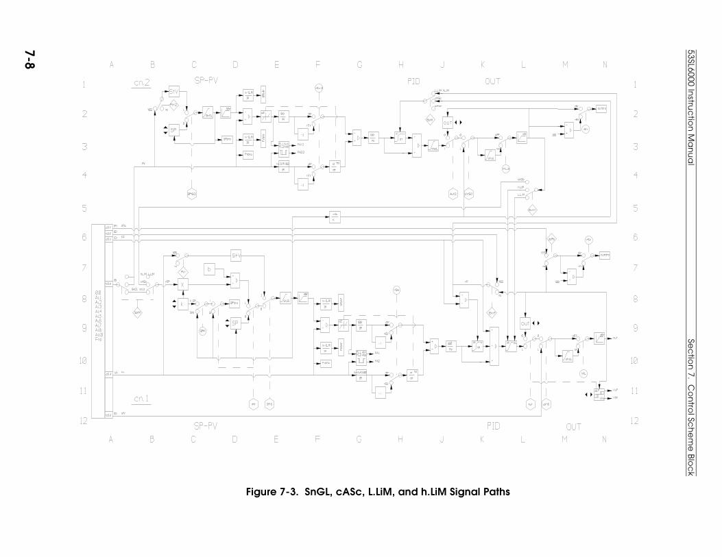
Figure 7-3. SnGL, cASc, L.LiM, and h.LiM Signal Paths
53SL6000 Instru
ctio
n M
an
ua
lSe
ctio
n 7. C
on
trol Sc
he
me
Blo
ck
7-8

Figure 7-4. Common Setpoint Logic Paths
Figure 7-5. Local Standard (Std) Setpoint Path
Section 7. Control Scheme Block 53SL6000 Instruction Manual
7-9

Figure 7-6. Remote Ratio Setpoint Path
Figure 7-7. StV Setpoint Tracking
53SL6000 Instruction Manual Section 7. Control Scheme Block
7-10
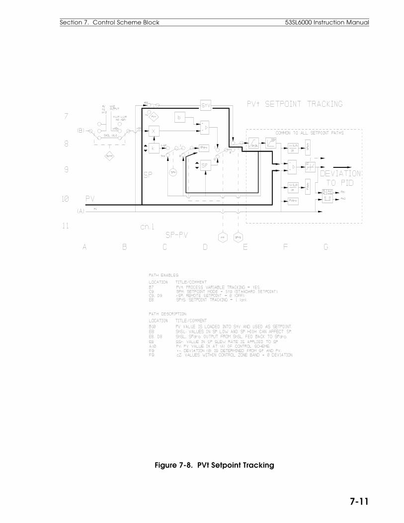
Figure 7-8. PVt Setpoint Tracking
Section 7. Control Scheme Block 53SL6000 Instruction Manual
7-11
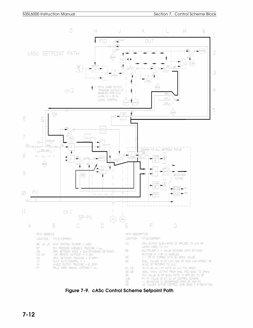
Figure 7-9. cASc Control Scheme Setpoint Path
53SL6000 Instruction Manual Section 7. Control Scheme Block
7-12
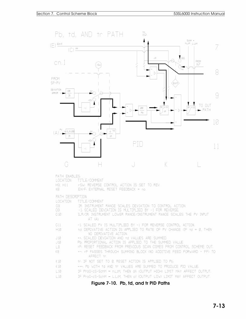
Figure 7-10. Pb, td, and tr PID Paths
Section 7. Control Scheme Block 53SL6000 Instruction Manual
7-13
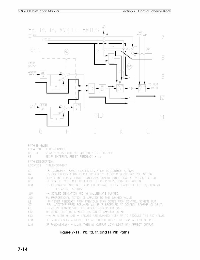
Figure 7-11. Pb, td, tr, and FF PID Paths
53SL6000 Instruction Manual Section 7. Control Scheme Block
7-14
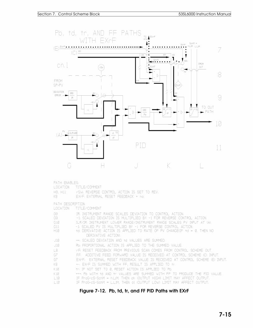
Figure 7-12. Pb, td, tr, and FF PID Paths with EXrF
Section 7. Control Scheme Block 53SL6000 Instruction Manual
7-15

Figure 7-13. Output Tracking Path
53SL6000 Instruction Manual Section 7. Control Scheme Block
7-16

Figure 7-14. Auto Output Path
Section 7. Control Scheme Block 53SL6000 Instruction Manual
7-17

Figure 7-15. Manual Output Path
53SL6000 Instruction Manual Section 7. Control Scheme Block
7-18

Figure 7-16. Auto Digital Output Path
Section 7. Control Scheme Block 53SL6000 Instruction Manual
7-19
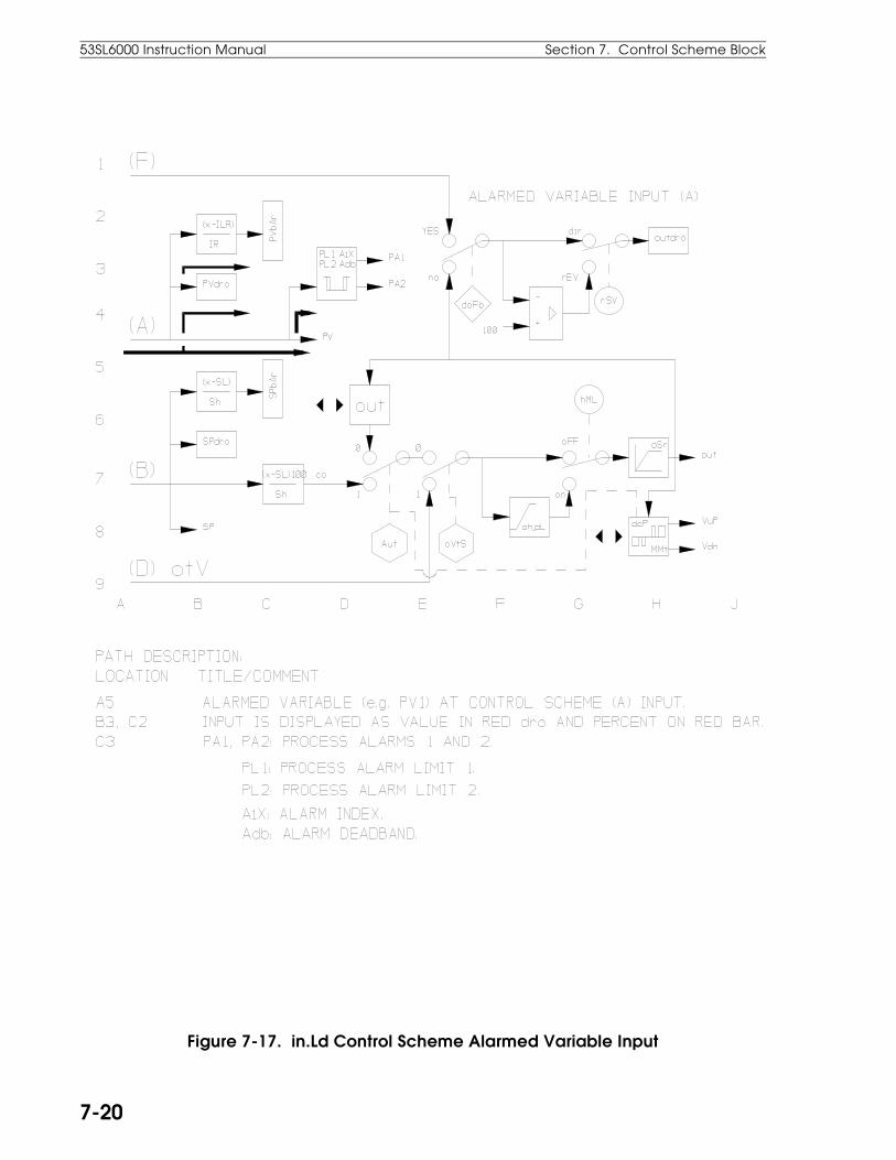
Figure 7-17. in.Ld Control Scheme Alarmed Variable Input
53SL6000 Instruction Manual Section 7. Control Scheme Block
7-20
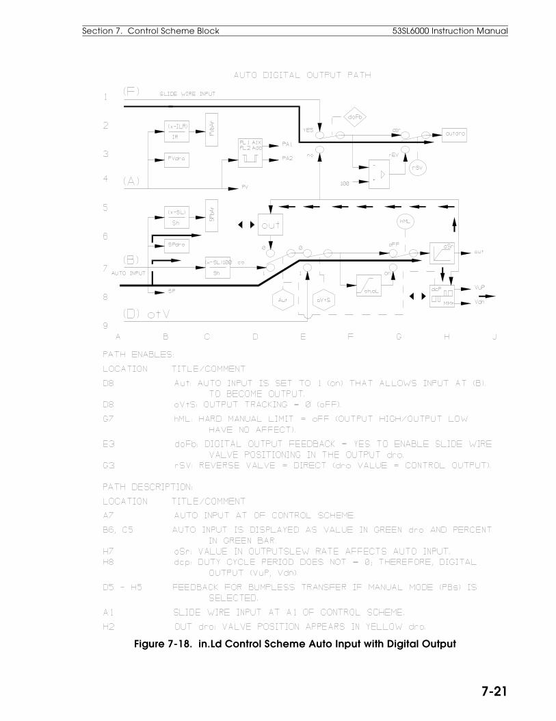
Figure 7-18. in.Ld Control Scheme Auto Input with Digital Output
Section 7. Control Scheme Block 53SL6000 Instruction Manual
7-21
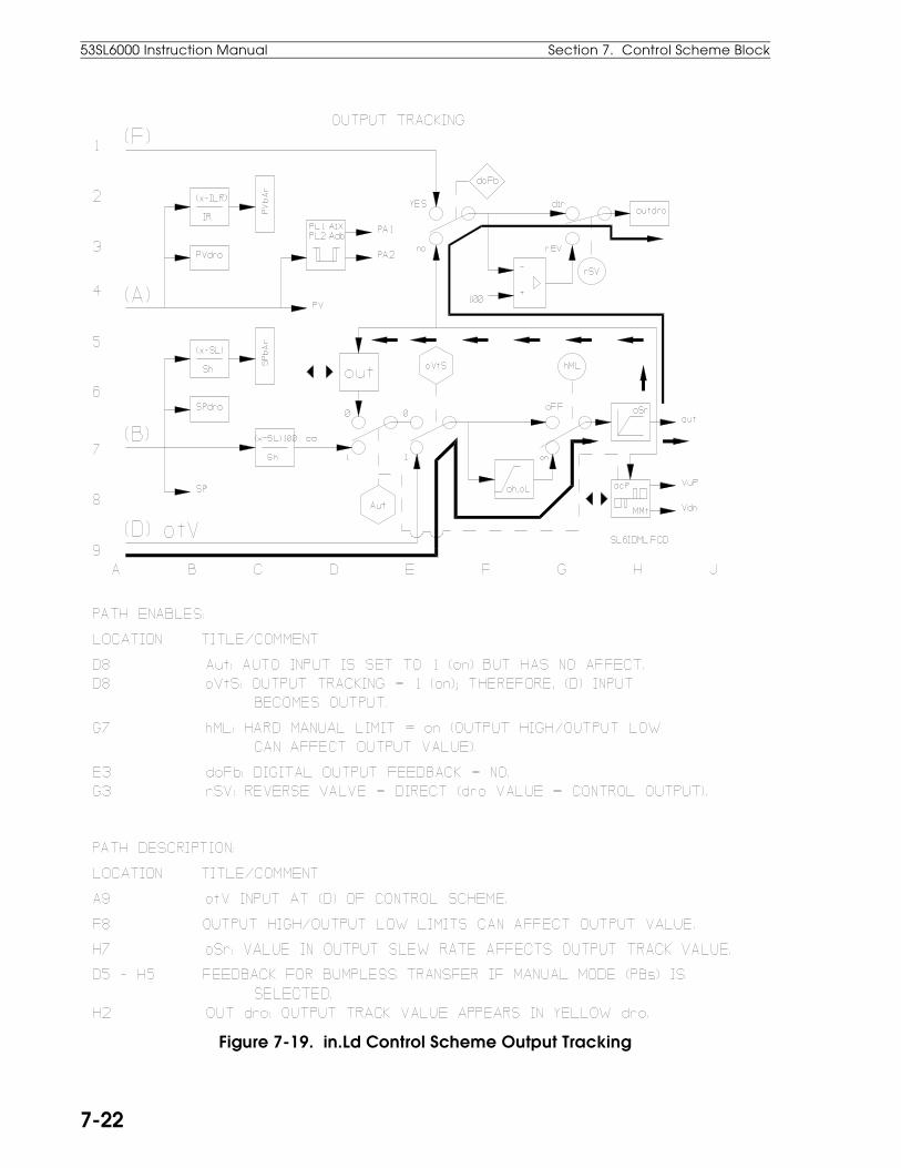
Figure 7-19. in.Ld Control Scheme Output Tracking
53SL6000 Instruction Manual Section 7. Control Scheme Block
7-22

Figure 7-20. in.Ld Control Scheme Manual Operation
Section 7. Control Scheme Block 53SL6000 Instruction Manual
7-23
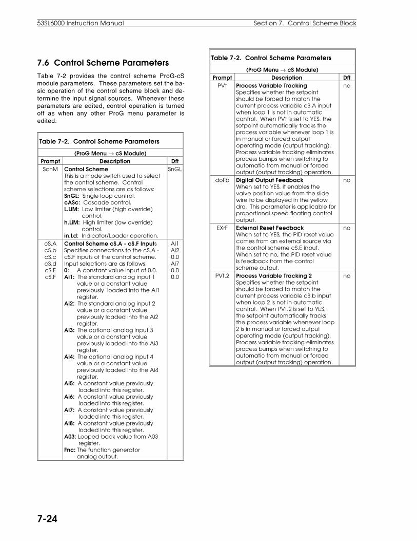
7.6 Control Scheme ParametersTable 7-2 provides the control scheme ProG-cSmodule parameters. These parameters set the ba-sic operation of the control scheme block and de-termine the input signal sources. Whenever theseparameters are edited, control operation is turnedoff as when any other ProG menu parameter isedited.
Table 7-2. Control Scheme Parameters
(ProG Menu → cS Module)Prompt Description DftSchM Control Scheme
This is a mode switch used to selectthe control scheme. Controlscheme selections are as follows:SnGL: Single loop control.cASc: Cascade control.L.LiM: Low limiter (high override) control.h.LiM: High limiter (low override) control.in.Ld: Indicator/Loader operation.
SnGL
cS.AcS.bcS.ccS.dcS.EcS.F
Control Scheme cS.A - cS.F InputsSpecifies connections to the cS.A -cS.F inputs of the control scheme.Input selections are as follows:0: A constant value input of 0.0.Ai1: The standard analog input 1 value or a constant value previously loaded into the Ai1 register.Ai2: The standard analog input 2 value or a constant value previously loaded into the Ai2 register.Ai3: The optional analog input 3 value or a constant value previously loaded into the Ai3 register.Ai4: The optional analog input 4 value or a constant value previously loaded into the Ai4 register.Ai5: A constant value previously loaded into this register.Ai6: A constant value previously loaded into this register.Ai7: A constant value previously loaded into this register.Ai8: A constant value previously loaded into this register.A03: Looped-back value from A03 register.Fnc: The function generator analog output.
Ai1Ai20.0Ai70.00.0
Table 7-2. Control Scheme Parameters
(ProG Menu → cS Module)Prompt Description Dft
PVt Process Variable TrackingSpecifies whether the setpointshould be forced to match thecurrent process variable cS.A inputwhen loop 1 is not in automaticcontrol. When PVt is set to YES, thesetpoint automatically tracks theprocess variable whenever loop 1 isin manual or forced outputoperating mode (output tracking).Process variable tracking eliminatesprocess bumps when switching toautomatic from manual or forcedoutput (output tracking) operation.
no
doFb Digital Output FeedbackWhen set to YES, it enables thevalve position value from the slidewire to be displayed in the yellowdro. This parameter is applicable forproportional speed floating controloutput.
no
EXrF External Reset FeedbackWhen set to YES, the PID reset valuecomes from an external source viathe control scheme cS.E input.When set to no, the PID reset valueis feedback from the controlscheme output.
no
PVt.2 Process Variable Tracking 2Specifies whether the setpointshould be forced to match thecurrent process variable cS.b inputwhen loop 2 is not in automaticcontrol. When PVt.2 is set to YES,the setpoint automatically tracksthe process variable whenever loop2 is in manual or forced outputoperating mode (output tracking).Process variable tracking eliminatesprocess bumps when switching toautomatic from manual or forcedoutput (output tracking) operation.
no
53SL6000 Instruction Manual Section 7. Control Scheme Block
7-24
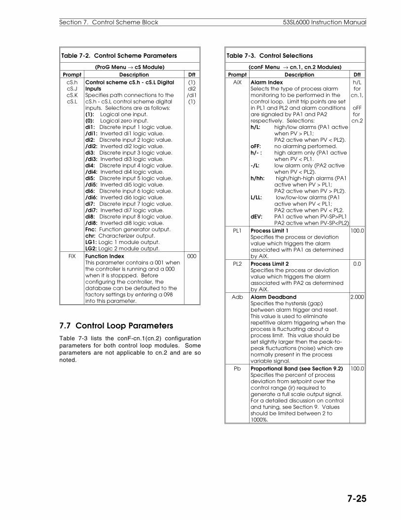
Table 7-2. Control Scheme Parameters
(ProG Menu → cS Module)Prompt Description Dft
cS.hcS.JcS.KcS.L
Control scheme cS.h - cS.L DigitalInputsSpecifies path connections to thecS.h - cS.L control scheme digitalinputs. Selections are as follows:(1): Logical one input.(0): Logical zero input.di1: Discrete input 1 logic value./di1: Inverted di1 logic value.di2: Discrete input 2 logic value./di2: Inverted di2 logic value.di3: Discrete input 3 logic value./di3: Inverted di3 logic value.di4: Discrete input 4 logic value./di4: Inverted di4 logic value.di5: Discrete input 5 logic value./di5: Inverted di5 logic value.di6: Discrete input 6 logic value./di6: Inverted di6 logic value.di7: Discrete input 7 logic value./di7: Inverted di7 logic value.di8: Discrete input 8 logic value./di8: Inverted di8 logic value.Fnc: Function generator output.chr: Characterizer output.LG1: Logic 1 module output.LG2: Logic 2 module output.
(1)di2/di1(1)
FiX Function IndexThis parameter contains a 001 whenthe controller is running and a 000when it is stoppped. Beforeconfiguring the controller, thedatabase can be defaulted to thefactory settings by entering a 098into this parameter.
000
7.7 Control Loop ParametersTable 7-3 lists the conF-cn.1(cn.2) configurationparameters for both control loop modules. Someparameters are not applicable to cn.2 and are sonoted.
Table 7-3. Control Selections
(conF Menu → cn.1, cn.2 Modules)Prompt Description Dft
AiX Alarm IndexSelects the type of process alarmmonitoring to be performed in thecontrol loop. Limit trip points are setin PL1 and PL2 and alarm conditionsare signaled by PA1 and PA2respectively. Selections:h/L: high/low alarms (PA1 active
when PV > PL1; PA2 active when PV < PL2).
oFF: no alarming performed.h/- : high alarm only (PA1 active
when PV < PL1.-/L: low alarm only (PA2 active
when PV < PL2).h/hh: high/high-high alarms (PA1
active when PV > PL1;PA2 active when PV > PL2).
L/LL: low/low-low alarms (PA1active when PV < PL1;PA2 active when PV < PL2.
dEV: PA1 active when PV-SP>PL1PA2 active when PV-SP<PL2)
h/Lfor
cn.1,
oFFfor cn.2
PL1 Process Limit 1Specifies the process or deviationvalue which triggers the alarmassociated with PA1 as determinedby AiX.
100.0
PL2 Process Limit 2Specifies the process or deviationvalue which triggers the alarmassociated with PA2 as determinedby AiX.
0.0
Adb Alarm DeadbandSpecifies the hystersis (gap)between alarm trigger and reset.This value is used to eliminaterepetitive alarm triggering when theprocess is fluctuating about aprocess limit. This value should beset slightly larger then the peak-to-peak fluctuations (noise) which arenormally present in the processvariable signal.
2.000
Pb Proportional Band (see Section 9.2)Specifies the percent of processdeviation from setpoint over thecontrol range (ir) required togenerate a full scale output signal.For a detailed discussion on controland tuning, see Section 9. Valuesshould be limited between 2 to1000%.
100.0
Section 7. Control Scheme Block 53SL6000 Instruction Manual
7-25
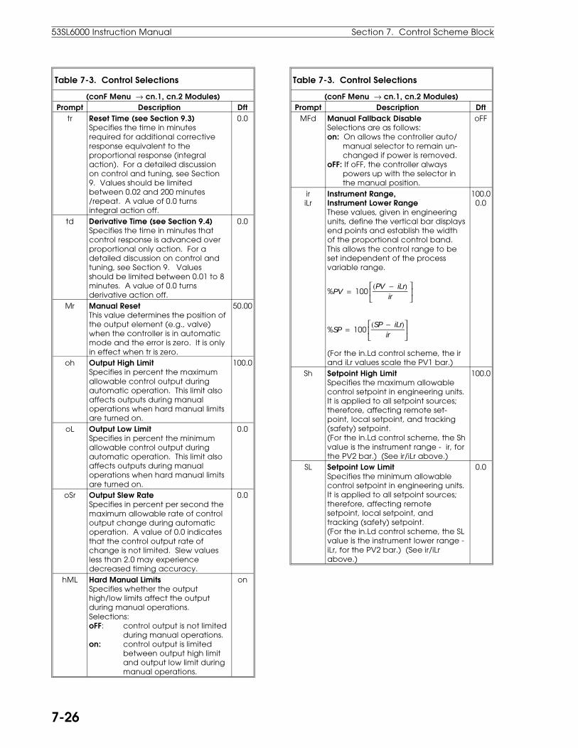
Table 7-3. Control Selections
(conF Menu → cn.1, cn.2 Modules)Prompt Description Dft
tr Reset Time (see Section 9.3)Specifies the time in minutesrequired for additional correctiveresponse equivalent to theproportional response (integralaction). For a detailed discussionon control and tuning, see Section9. Values should be limitedbetween 0.02 and 200 minutes/repeat. A value of 0.0 turnsintegral action off.
0.0
td Derivative Time (see Section 9.4) Specifies the time in minutes thatcontrol response is advanced overproportional only action. For adetailed discussion on control andtuning, see Section 9. Valuesshould be limited between 0.01 to 8minutes. A value of 0.0 turnsderivative action off.
0.0
Mr Manual ResetThis value determines the position ofthe output element (e.g., valve)when the controller is in automaticmode and the error is zero. It is onlyin effect when tr is zero.
50.00
oh Output High LimitSpecifies in percent the maximumallowable control output duringautomatic operation. This limit alsoaffects outputs during manualoperations when hard manual limitsare turned on.
100.0
oL Output Low LimitSpecifies in percent the minimumallowable control output duringautomatic operation. This limit alsoaffects outputs during manualoperations when hard manual limitsare turned on.
0.0
oSr Output Slew RateSpecifies in percent per second themaximum allowable rate of controloutput change during automaticoperation. A value of 0.0 indicatesthat the control output rate ofchange is not limited. Slew valuesless than 2.0 may experiencedecreased timing accuracy.
0.0
hML Hard Manual LimitsSpecifies whether the outputhigh/low limits affect the outputduring manual operations.Selections:oFF: control output is not limited
during manual operations.on: control output is limited
between output high limitand output low limit duringmanual operations.
on
Table 7-3. Control Selections
(conF Menu → cn.1, cn.2 Modules)Prompt Description Dft
MFd Manual Fallback DisableSelections are as follows:on: On allows the controller auto/ manual selector to remain un- changed if power is removed.oFF: If oFF, the controller always powers up with the selector in the manual position.
oFF
iriLr
Instrument Range,Instrument Lower RangeThese values, given in engineeringunits, define the vertical bar displaysend points and establish the widthof the proportional control band.This allows the control range to beset independent of the processvariable range.
%PV = 100
(PV − iLr)ir
%SP = 100
(SP − iLr)ir
(For the in.Ld control scheme, the irand iLr values scale the PV1 bar.)
100.00.0
Sh Setpoint High LimitSpecifies the maximum allowablecontrol setpoint in engineering units.It is applied to all setpoint sources;therefore, affecting remote set-point, local setpoint, and tracking(safety) setpoint.(For the in.Ld control scheme, the Shvalue is the instrument range - ir, forthe PV2 bar.) (See ir/iLr above.)
100.0
SL Setpoint Low LimitSpecifies the minimum allowablecontrol setpoint in engineering units.It is applied to all setpoint sources;therefore, affecting remotesetpoint, local setpoint, andtracking (safety) setpoint.(For the in.Ld control scheme, the SLvalue is the instrument lower range -iLr, for the PV2 bar.) (See ir/iLrabove.)
0.0
53SL6000 Instruction Manual Section 7. Control Scheme Block
7-26

Table 7-3. Control Selections
(conF Menu → cn.1, cn.2 Modules)Prompt Description Dft
SSr Setpoint Slew RateSpecifies in engineering units persecond the maximum allowablerate of setpoint change (or PV2 rateof change for the in.Ld controlscheme). When employed, thegreen bar represents the setpoint asit is applied to control (slew limited),while the green dro represents thetarget setpoint value. A value of 0.0indicates that the setpoint rate ofchange is not limited. Slew valuesless than 2.0 may experiencedecreased timing accuracy.
0.0
StV Setpoint Track ValueSpecifies in engineering units thedesired setpoint when the cS.L input(SWSt) is 0 and the PVt (ProcessVariable Tracking) path enable isset to no. Using cS.L as the selectorcontrol allows the setpoint trackvalue to be treated as either asafety value or a fixed secondarysetpoint value. When PVT is set toYES and the controller is notoperating in auto (PID output), thesetpoint track value is automaticallyloaded with the current processvariable on the cS.A input (cS.binput for loop 2). This providesbumpless transfer from manual toauto operation or from outputtracking to auto operation becausethe setpoint is forced to match thePV before the switch to auto ismade.
0.0
SPM(cn.1only)
Setpoint Mode SelectDetermines the operation of thesetpoint push buttons when remotesetpoint operation is selected.Selections:Std: setpoint push buttons have
no affect when R is selected with the R/L push button..K-SP: setpoint push buttons modi-
fy K1( ratio) value when RR is selected with the R/Lpush button.
Std
K1 Remote Setpoint RatioThis parameter and RemoteSetpoint Bias (b1) allow the remotesetpoint input to be modified priorto input at the setpoint generator.
SP = (RSP × K1) + B1
1
Table 7-3. Control Selections
(conF Menu → cn.1, cn.2 Modules)Prompt Description Dft
b1 Remote Setpoint BiasThis parameter and RemoteSetpoint Ratio (K1) allow the remotesetpoint to be modified prior toinput at the setpoint generator.
SP = (RSP × K1) + B1
0
cZ Control ZoneSpecifies in engineering units anarea around the setpoint where theprocess variable is considered to beat setpoint (no error). When theprocess variable is within this area,the control output is held steady atthe integral value as determined bytr and Mr. Control Zone is used toreduce valve wear where processdynamics cause output oscillations(hunting) when the process is nearits setpoint.
cZ cZ
0.0
rSW Reverse Control ActionSpecifies the output responserequired to correct for process error.Selections:dir: output must increase to
eliminate a positive error(PV-SP).
reV: output must decrease toeliminate a positive error(PV-SP).
rEV
dP Decimal Point LocationFixes the location of the decimalpoint in each dro for the operatordisplay. Selections:PPPP: values between -999 and
9999.PPP.d: values between -99.9 and
999.9.PP.dd: values between -9.99 and
99.99.P.ddd: values between -.999 and
9.999.
PPP.d
Section 7. Control Scheme Block 53SL6000 Instruction Manual
7-27

Table 7-3. Control Selections
(conF Menu → cn.1, cn.2 Modules)Prompt Description Dft
rSv(cn.1only)
Reverse ValveSpecifies whether 100% outputshould be displayed in the output(yellow) dro as 100% or 0%. Thisallows the output dro to be set tocorrespond to a preferred valverepresentation of output. Selections:dir: 100% control output = 100%
displayed.rEV: 100% control output = 0%
displayed.
dir
MMt(cn.1only)
Minimum Manual Jog TimeDesignates the mode of manualoperation associated with the VuPand Vdn logic signals. When MMt =0, VuP and Vdn are always a pulsewidth modulated (PWM)representation of the control OUTsignal. The PWM period isdetermined by the dcP parameter.When MMt = non-zero, VuP and Vdnare PWM representations inautomatic operation; however, inmanual operation, they are onlyactive when either of the outputpush buttons is pressed. A non-zerovalue entered for MMt represents inpercent the minimum duty cycleperiod the logic values VuP andVdn will be a 1 whenever the outputpush buttons are momentarilydepressed or when a networkeddevice generates an associatedpush button operation.
Non-zero operation:
0.0
OUTPB
VuP
dcP
Sec.
0 1 2 3 4 25 26 27 28 29 30
dcP = 30 seconds
MMt (MMt = 5% dcP)
Table 7-3. Control Selections
(conF Menu → cn.1, cn.2 Modules)Prompt Description Dft
dcP(cn.1only)
Duty Cycle PeriodSpecifies in seconds, the length ofthe cycle period over which thedigital outputs VuP and Vdn arecalculated. This time must be setbased on the characteristics of thefinal control element and theamount of cycling permitted. Forminimum cycling of the final controlelement, the period should be set tomatch the end-to-end travel time ofthe element. To operate the digitaloutputs in a time proportioningmanner, much shorter cycle timesare required. Because each cycleperiod is divided into 0.05 secondpieces, the resolution of the outputis determined by the length of thecycle period. For example: If dcP is10 seconds, then the period willcontain 200 pieces (10/0.05 = 200),each being 0.5% of the 10 secondperiod. If the controller output(OUT) value is 27.65 (%) at the startof the period, then the VuP logic willremain a "1" for 2.8 seconds (27.65%rounded to the closest 0.5% = 28.1or 28%; 0.28 x 10 seconds = 2.8seconds). 2.8 seconds is equivalentto 56 pieces. The cycle period willbe a "0" for the remainder of theperiod, which is 7.2 seconds (144pieces).
0.0
7.8 Control Scheme Signal Connector Pin AssignmentsAny one of six control strategies can be configuredvery quickly from a defaulted controller (ProG-cS-FiX = 98) by selecting the appropriate controlscheme and setting several parameters. The sig-nal connector pin assignments vary for these con-trol strategies as illustrated in Figure 7-21. The sixcontrol strategies are covered as part of the infor-mation provided in Section 8. The six controlstrategies are as follows:
• Single Loop Controller with Remote Setpoint
• Single Loop Ratio Controller
• Dual Loop Cascade Controller
• Dual Loop High Limited Controller
• Dual Loop Low Limited Controller
• Auto/Manual Station
53SL6000 Instruction Manual Section 7. Control Scheme Block
7-28

Figure 7-21. Control Schemes Signal Connector Pin Assignments
Sec
tion
7. Co
ntro
l Sch
em
e B
loc
k53SL6000 In
struc
tion
Ma
nu
al
7-29

This section provides information to implementeight commonly used control strategies:
• Single Loop Control with Remote Setpoint.
• Analog Back-up Control.
• Ratio Control.
• Auto/Manual Selector.
• Single Station Cascade Control.
• Single Station Override Control.
• Dual Indicator with Re-Transmitted PV.
• Proportional Speed Floating Control
Information for each strategy is presented in thesame order. There is a brief overview of the controlstrategy operation with a process illustration andan illustration of the signal connector pin assign-ments, which is followed by descriptive sections ofthe connector signals. The applicable parametersthat may require configuring are also included inthese sections.
Many signal paths can be altered in the controller.To simplify the presentation, it is assumed the pathconfiguration selections are left at the factory set-tings unless specified otherwise in the example.
Also provided, is a description of time proportionaloutput, which can be applied to any of the controlstrategies presented in this section.
8.1 Single Loop Control with Remote Setpoint Single loop control with remote setpoint is the con-troller standard factory set functionality (controllerdefault settings and the SnGL control scheme).
A single loop control strategy with remote setpointis illustrated in Figure 8-1. In single loop control, acontinuous output is calculated from the differencebetween the process variable (AI1) feedback signalsent from a field transmitter (e.g., flow meter) anda setpoint (SP) value. The output is calculated withthe controller PID algorithm, which has propor-tional, integral, and derivative terms. The effectthese terms have on the output calculation de-pends on the PID configuration selections (Pb, tr,and td). As the output (AO1) is determined, it isapplied to a final control element (e.g., valve) torestore the process to the setpoint value.
The output can also be set manually at the control-ler, whereby the PID algorithm calculation is notused. The setpoint can be set locally at the control-ler or it can originate from a remote source (AI2). Ifthe alarm limits are configured, the controller willactivate an annunciator whenever the PV exceedsthe configured tolerable limits of change.
Figure 8-1. Single Loop Application
The signal connector is illustrated in Figure 8-2 andthe connector pin assignment descriptions areprovied in the sections that follow. These sectionsalso contain the applicable display prompts thatmay require configuration changes.
Figure 8-2. Single Loop Signals
8.0 Eight Control Strategies
Section 8. Eight Control Strategies 53SL6000 Instruction Manual
8-1
8.1.1 AI1 - Process Variable InputThis analog input signal value is compared to thecontrol setpoint to determine the control outputvalue.
Applicable parameters that may require configura-tion changes:Section 5.2, conF-Ai.1-(SPan, ZEro, SQrt, bASE,dFLt).For PV alarms:Section 7.7, conF-cn.1-(AiX, PL1, PL2, Adb).
8.1.2 AI2 - Remote Setpoint InputThis analog input signal value is used as the con-trol setpoint when remote (R) operation is selectedwith the display panel push button and remote set-point is enabled (closed) by DI2.
Applicable parameters that may require configura-tion changes:Section 5.2, conF-Ai.2-(SPan, ZEro, SQrt, bASE,dFLt).Section 7.7, conF-cn.1-(Sh, SL, SSr).
8.1.3 DO1 - PV High Alarm Contact OutD01 is closed (on) when the process variable valueis not within the alarm limit 1 (PL1) setting.
Applicable parameter that may require configura-tion change:Section 5.6, ProG-do-inV1.
8.1.4 DO2 - PV Low Alarm Contact OutD02 is closed (on) when the process variable valueis not within the alarm limit 2 (PL2) setting.
Applicable parameter that may require configura-tion change:Section 5.6, ProG-do-inV2.
8.1.5 DI1 - Force Control Output Contact InputThis is a closed contact or low active signal (0-1 Vdc). When a closed contact or 0-1 V dc signal ispresent on this input, the control output value isapplied to the value of Ai7 (the control scheme Dinput accepts the force control value and cS.d isdefaulted to select Ai7).
Applicable parameters that may require configura-tion changes:To enter a Force Output value in register Ai7:Section 5.2, ProG-Ai-Ai.7 or oPEr-Ai7.
8.1.6 DI2 - Remote Enable Contact InputThis is a low active signal (0-1 V dc). When a 0-1V dc signal is present on this input, the operatorcan select the Remote Setpoint input at AI2 as thesetpoint value with the R/L push button. The Re-mote LED flashes if the R/L push button is pressedand this signal is not low to enable remote setpointcontrol.
Applicable parameter that may require configura-tion change:None.
8.1.7 AO1 - Control OutputThis is the 4-20 mA signal that drives the finalcontrol element.
Applicable parameters that may require configura-tion changes:Section 7.7, conF-cn.1-(oh, oL, hML, oSr, rSW,rSV).For control related prompts:Section 7.7, conF-cn.1-(ir, iLr, Mr).Sections 7.7, 9.2, 9.3, and 9.4, conF-cn.1-(Pb, tr,td).
8.1.8 SchM SelectionSingle loop control is implemented with the control-ler default settings and SnGL (single loop) selectedfrom the SchM prompt of the cS module.
Applicable parameter that may require configura-tion changes:Section 7.6, ProG-cS-SchM.
53SL6000 Instruction Manual Section 8. Eight Control Strategies
8-2
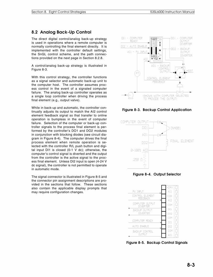
8.2 Analog Back-Up ControlThe direct digital control/analog back-up strategyis used in operations where a remote computer isnormally controlling the final element directly. It isimplemented with the controller default settings,the SnGL control scheme, and the path connec-tions provided on the next page in Section 8.2.8.
A control/analog back-up strategy is illustrated inFigure 8-3.
With this control strategy, the controller functionsas a signal selector and automatic back-up unit tothe computer host. The controller assumes proc-ess control in the event of a signaled computerfailure. The analog back-up controller operates asa single loop controller when driving the processfinal element (e.g., output valve).
While in back-up and automatic, the controller con-tinually adjusts its output to match the AI2 controlelement feedback signal so that transfer to onlineoperation is bumpless in the event of computerfailure. Selection of the computer or back-up con-troller signals to the process final element is per-formed by the controller’s DO1 and DO2 modulesin conjunction with blocking diodes (see circuit dia-gram in Figure 8-4). The computer drives the finalprocess element when remote operation is se-lected with the controller R/L push button and digi-tal input DI1 is closed (0-1 V dc); otherwise, thecomputer’s control signal is diverted and the outputfrom the controller is the active signal to the proc-ess final element. Unless DI2 input is open (4-24 Vdc signal), the controller is not permitted to operatein automatic mode.
The signal connector is illustrated in Figure 8-5 andthe connector pin assignment descriptions are pro-vided in the sections that follow. These sectionsalso contain the applicable display prompts thatmay require configuration changes.
Figure 8-3. Backup Control Application
Figure 8-4. Output Selector
Figure 8-5. Backup Control Signals
Section 8. Eight Control Strategies 53SL6000 Instruction Manual
8-3

8.2.1 AI1 - Process Variable InputThis analog input signal value is compared to thecontrol setpoint to determine the control outputvalue.
Applicable parameters that may require configura-tion changes:Section 5.2, conF-Ai.1-(SPan, ZEro, SQrt, bASE,dFLt).For PV alarms:Section 7.7, conF-cn.1-(AiX, PL1, PL2, Adb).
8.2.2 AI2 - Control Element FeedbackThis is a feedback signal from the diverter circuit tothe controller that indicates the position of the finalelement (e.g., valve) so that if operation transfer tothe controller becomes necessary, it will be bum-pless.
Applicable parameters that may require configura-tion changes:Section 5.2, conF-Ai.2-(SPan, ZEro, SQrt, bASE,dFLt).
8.2.3 DO1 - Computer Output DiverterWhen open, the computer output path is throughthe diverter circuit diode to the final element (e.g.,valve).
Applicable parameter that may require configura-tion change:Section 5.6, ProG-do-inV1.
8.2.4 DO2 - Backup Output DiverterWhen open, the controller output path is throughthe diverter circuit diode to the final element (e.g.,valve).
Applicable parameter that may require configura-tion change:Section 5.6, ProG-do-inV2.
8.2.5 DI1 - Computer ReadyThis is a low active signal (0-1 V dc) that enablesthe computer to drive the final element when R isselected with the R/L push button.
Applicable parameter that may require configura-tion change:None.
8.2.6 DI2 - Auto EnableThis is a high active signal (4-24 V dc) that enablesthe controller to drive the final element when L isselected with the R/L push button and the controlleris in automatic. The Auto LED flashes if the A/M
push button is pressed and this signal is not 4-24 Vdc to enable auto control.
Applicable parameter that may require configura-tion change:None.
8.2.7 A01 - Backup Control OutputThis is the 4-20 mA output signal that drives thefinal control element if operation is transferred fromthe computer to the controller.
Applicable parameters that may require configura-tion changes:Section 7.7, conF-cn.1-(oh, oL, hML, oSr, rSW,rSV).For control related prompts:Section 7.7, conF-cn.1-(ir, iLr, Mr).Sections 7.7, 9.2, 9.3, and 9.4, conF-cn.1-(Pb, tr,td).
8.2.8 SchM Selection and Path ConnectionsAnalog control is implemented with the controllerdefault settings, control scheme 1, and SnGL (sin-gle loop control) selected from the SchM prompt ofthe cS module.
Applicable parameter that may require configura-tion changes:Section 7.6, ProG-cS-SchM.
Applicable path connections that are required:
ProG-cS-cS.b = Ao3.ProG-cS-cS.d = Ai2.ProG-cS-cS.h = di2¤ (inverted).ProG-cS-cS.J = di1.ProG-cS-cS.K = LG1.ProG-LG-LG1.A = do8.ProG-LG-LG1.M = Xor.ProG-LG-LG3.A = rMt.ProG-LG-LG3.M = And.ProG-Ao-Ao3.i = SP.ProG-do-do1.i = LG3.ProG-do-do2.i = LG3.ProG-do-inV1 = 0-on.ProG-do-do8.i = LG3.
53SL6000 Instruction Manual Section 8. Eight Control Strategies
8-4
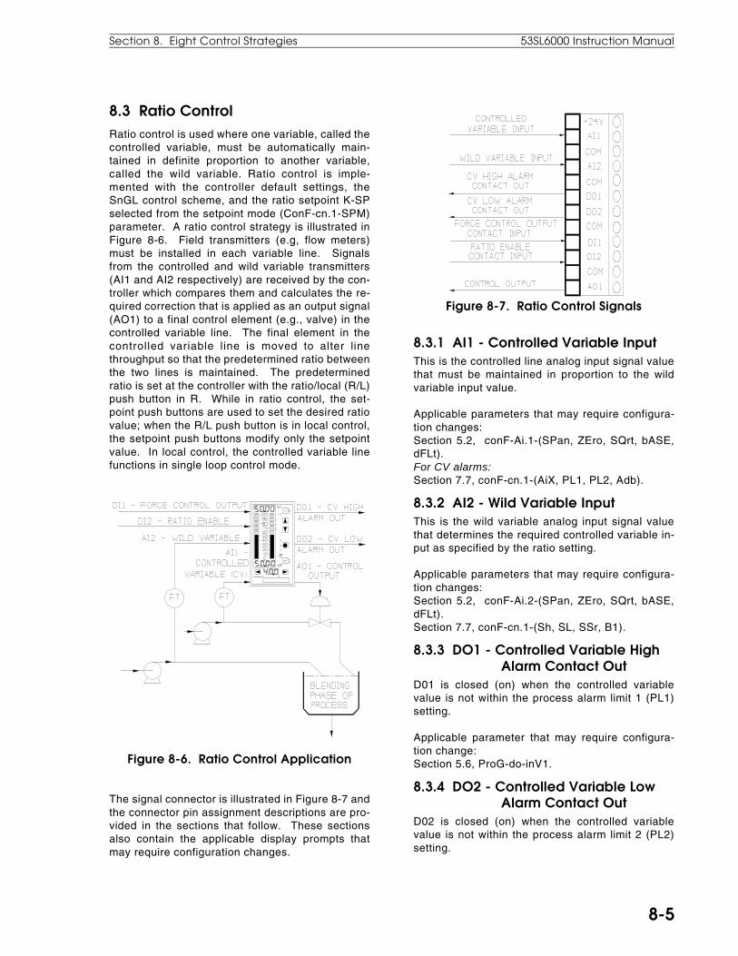
8.3 Ratio ControlRatio control is used where one variable, called thecontrolled variable, must be automatically main-tained in definite proportion to another variable,called the wild variable. Ratio control is imple-mented with the controller default settings, theSnGL control scheme, and the ratio setpoint K-SPselected from the setpoint mode (ConF-cn.1-SPM)parameter. A ratio control strategy is illustrated inFigure 8-6. Field transmitters (e.g, flow meters)must be installed in each variable line. Signalsfrom the controlled and wild variable transmitters(AI1 and AI2 respectively) are received by the con-troller which compares them and calculates the re-quired correction that is applied as an output signal(AO1) to a final control element (e.g., valve) in thecontrolled variable line. The final element in thecontrolled variable line is moved to alter linethroughput so that the predetermined ratio betweenthe two lines is maintained. The predeterminedratio is set at the controller with the ratio/local (R/L)push button in R. While in ratio control, the set-point push buttons are used to set the desired ratiovalue; when the R/L push button is in local control,the setpoint push buttons modify only the setpointvalue. In local control, the controlled variable linefunctions in single loop control mode.
Figure 8-6. Ratio Control Application
The signal connector is illustrated in Figure 8-7 andthe connector pin assignment descriptions are pro-vided in the sections that follow. These sectionsalso contain the applicable display prompts thatmay require configuration changes.
Figure 8-7. Ratio Control Signals
8.3.1 AI1 - Controlled Variable InputThis is the controlled line analog input signal valuethat must be maintained in proportion to the wildvariable input value.
Applicable parameters that may require configura-tion changes:Section 5.2, conF-Ai.1-(SPan, ZEro, SQrt, bASE,dFLt).For CV alarms:Section 7.7, conF-cn.1-(AiX, PL1, PL2, Adb).
8.3.2 AI2 - Wild Variable InputThis is the wild variable analog input signal valuethat determines the required controlled variable in-put as specified by the ratio setting.
Applicable parameters that may require configura-tion changes:Section 5.2, conF-Ai.2-(SPan, ZEro, SQrt, bASE,dFLt).Section 7.7, conF-cn.1-(Sh, SL, SSr, B1).
8.3.3 DO1 - Controlled Variable High Alarm Contact OutD01 is closed (on) when the controlled variablevalue is not within the process alarm limit 1 (PL1)setting.
Applicable parameter that may require configura-tion change:Section 5.6, ProG-do-inV1.
8.3.4 DO2 - Controlled Variable Low Alarm Contact OutD02 is closed (on) when the controlled variablevalue is not within the process alarm limit 2 (PL2)setting.
Section 8. Eight Control Strategies 53SL6000 Instruction Manual
8-5

Applicable parameter that may require configura-tion change:Section 5.6, ProG-do-inV2.
8.3.5 DI1 - Force Control Output Contact InputThis is a closed contact or low active signal (0-1 Vdc). When a closed contact or 0-1 V dc signal ispresent on this input, the control output value isapplied to the value of Ai7 (the control scheme Dinput accepts the force control value and cS.d isdefaulted to select Ai7).
Applicable parameters that may require configura-tion changes:To enter a Force Output value in register Ai7:Section 5.2, ProG-Ai-Ai.7 or oPEr-Ai7.
8.3.6 DI2 - Ratio Enable Contact InputThis is a low active signal (0-1 V dc). When a 0-1V dc signal is present on this input, the operatorcan select ratio operation with the R/L push button.The R LED flashes if the R/L push button ispressed and this signal is not low to enable ratiocontrol.
Applicable parameter that may require configura-tion change:None.
8.3.7 Control OutputThis is the 4-20 mA signal that drives the finalcontrol element.
Applicable parameters that may require configura-tion changes:Section 7.7, conF-cn.1-(oh, oL, hML, oSr, rSW,rSV).For control related prompts:Section 7.7, conF-cn.1-(ir, iLr, Mr).Sections 7.7, 9.2, 9.3, and 9.4, conF-cn.1-(Pb, tr,td).
8.3.8 SPM = K-SPRatio control is implemented with the controller de-fault settings, control scheme 1, and K-SP selectedfrom the SPM prompt of the cn.1 menu.
Applicable parameter that requires configurationchange:Section 7.7, conF-cn.1-SPM.
8.3.9 SchM SelectionRatio control is implemented with the controller de-fault settings and SnGL (single loop) selected fromthe SchM prompt of the cS module.
Applicable parameter that may require configura-tion changes:Section 7.6, ProG-cS-SchM.
53SL6000 Instruction Manual Section 8. Eight Control Strategies
8-6

8.4 Auto/Manual SelectorAn auto/manual selector application is illustrated inFigure 8-8. This application is implemented withthe controller default settings and the in.Ld controlscheme. The auto/manual selector default settingsallow auto-throughput when Auto is selected withthe A/M push button. In automatic, the signal onAI2 is passed through to the station’s output (AO1).Manual operation occurs when M is selected withthe A/M push button. In manual, the station outputis controlled with the output push buttons. Transferfrom automatic to manual is bumpless. There is noPID control performed by the automatic/manual se-lector; however, the station monitors AI1 foralarmed conditions, which are signaled with DO1and DO2. If DI1 is closed, the force output signalappears at A01.
Figure 8-8. A/M Selector Application
The force output signal can be applied to an analoginput (e.g., universal analog input module AI3 orAI4) from an external source, or it can be a con-stant value entered into one of the controller analoginput registers. AI7 is shown in Figure 8-8 in pa-renthesis to indicate the controller does not haveany optional AI inputs and that this value is a con-stant that was entered into AI7.
The signal connector is illustrated in Figure 8-9 andthe connector pin assignment descriptions are pro-vided in the sections that follow. These sectionsalso contain the applicable display prompts thatmay require configuration changes.
Figure 8-9. A/M Selector Signals
8.4.1 AI1 - Process Variable 1 InputThis analog signal is the designated input variablethat is checked to be within acceptable processlimits.
Applicable parameters that may require configura-tion changes:Section 5.2, conF-Ai.1-(SPan, ZEro, SQrt, bASE,dFLt).For PV alarms:Section 7.7, conF-cn.1-(AiX, PL1, PL2, Adb).
8.4.2 AI2 - Process Variable 2 Input (Auto)This analog signal is gated through as the AO1selector output if force output is not active and autois selected with the A/M push button.
Applicable parameters that may require configura-tion changes:Section 5.2, conF-Ai.2-(SPan, ZEro, SQrt, bASE,dFLt).
8.4.3 DO1 - PV1 High Alarm Contact OutD01 is closed (on) when the alarmed process vari-able value, PV1, is not within the process alarmlimit 1 (PL1) setting.
Applicable parameter that may require configura-tion change:Section 5.6, ProG-do-inV1.
Section 8. Eight Control Strategies 53SL6000 Instruction Manual
8-7

8.4.4 D02 - PV1 Low Alarm Contact OutD02 is closed (on) when the alarmed process vari-able value, PV1, is not within the process alarmlimit 2 (PL2) setting.
Applicable parameter that may require configura-tion change:Section 5.6, ProG-do-inV2.
8.4.5 DI1 Force Output Contact InputThis is a closed contact or low active signal (0-1 Vdc). When a closed contact or 0-1 V dc signal ispresent on this input, the control output value isapplied to the value of Ai7 (the control scheme Dinput accepts the force control value and cS.d isdefaulted to select Ai7).
Applicable parameters that may require configura-tion changes:To enter a Force Output value in register Ai7:Section 5.2, ProG-Ai-Ai.7 or oPEr-Ai7.
8.4.7 A01 - PV2 Re-Transmit (Auto)This is the selected analog 4-20 mA output signalthat is sent to the final control element.
Applicable parameters that may require configura-tion changes:Section 7.7, conF-cn.1-(oh, oL, hML, oSr, rSW,rSV).For control related prompts:Section 7.7, conF-cn.1-(ir, iLr).
8.4.8 SchM SelectionThe auto/manual selector is implemented with thecontroller default sett ings and in.Ld ( indica-tor/loader) selected from the SchM prompt of thecS module.
Applicable parameter that may require configura-tion changes:Section 7.6, ProG-cS-SchM.
53SL6000 Instruction Manual Section 8. Eight Control Strategies
8-8
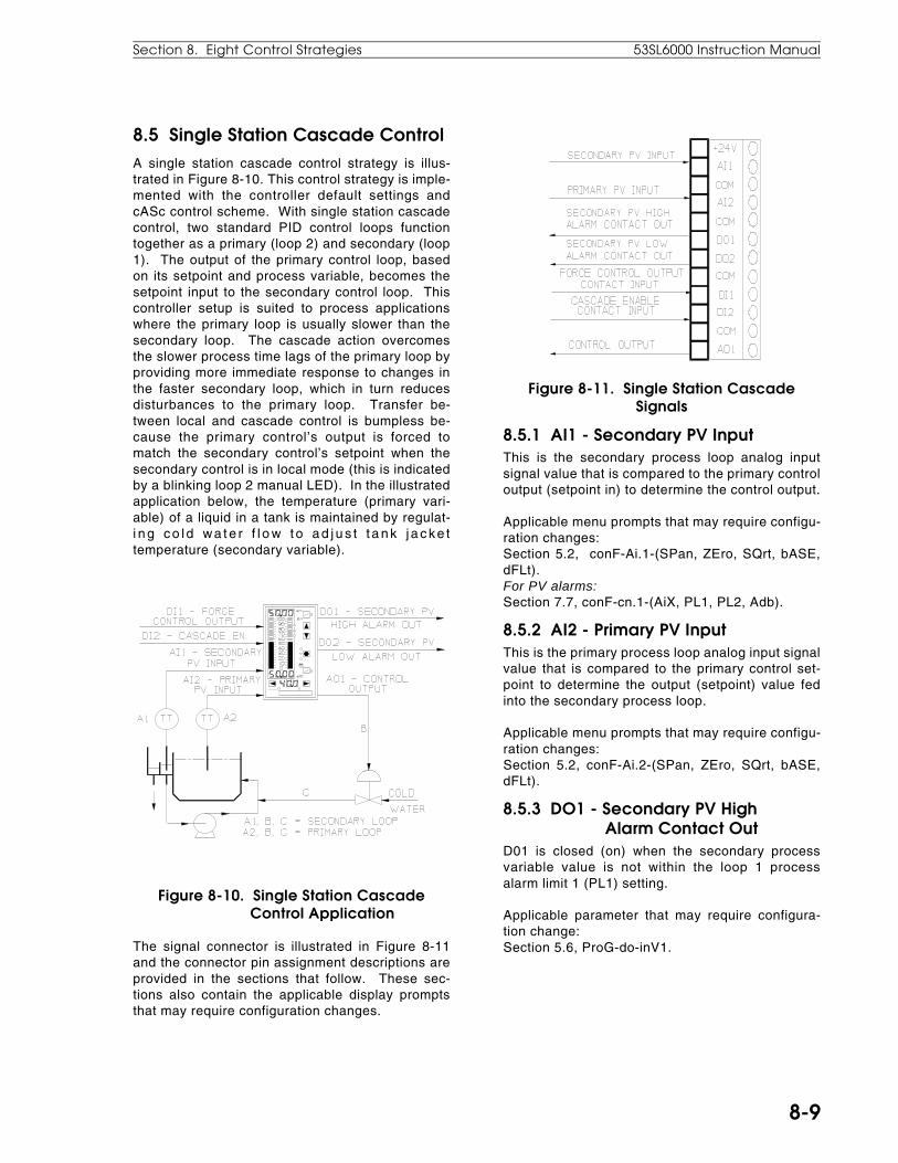
8.5 Single Station Cascade ControlA single station cascade control strategy is illus-trated in Figure 8-10. This control strategy is imple-mented with the controller default settings andcASc control scheme. With single station cascadecontrol, two standard PID control loops functiontogether as a primary (loop 2) and secondary (loop1). The output of the primary control loop, basedon its setpoint and process variable, becomes thesetpoint input to the secondary control loop. Thiscontroller setup is suited to process applicationswhere the primary loop is usually slower than thesecondary loop. The cascade action overcomesthe slower process time lags of the primary loop byproviding more immediate response to changes inthe faster secondary loop, which in turn reducesdisturbances to the primary loop. Transfer be-tween local and cascade control is bumpless be-cause the primary control’s output is forced tomatch the secondary control’s setpoint when thesecondary control is in local mode (this is indicatedby a blinking loop 2 manual LED). In the illustratedapplication below, the temperature (primary vari-able) of a liquid in a tank is maintained by regulat-i ng co l d wa t e r f l o w t o ad j u s t t a nk j a cke ttemperature (secondary variable).
Figure 8-10. Single Station Cascade Control Application
The signal connector is illustrated in Figure 8-11and the connector pin assignment descriptions areprovided in the sections that follow. These sec-tions also contain the applicable display promptsthat may require configuration changes.
Figure 8-11. Single Station CascadeSignals
8.5.1 AI1 - Secondary PV InputThis is the secondary process loop analog inputsignal value that is compared to the primary controloutput (setpoint in) to determine the control output.
Applicable menu prompts that may require configu-ration changes:Section 5.2, conF-Ai.1-(SPan, ZEro, SQrt, bASE,dFLt).For PV alarms:Section 7.7, conF-cn.1-(AiX, PL1, PL2, Adb).
8.5.2 AI2 - Primary PV InputThis is the primary process loop analog input signalvalue that is compared to the primary control set-point to determine the output (setpoint) value fedinto the secondary process loop.
Applicable menu prompts that may require configu-ration changes:Section 5.2, conF-Ai.2-(SPan, ZEro, SQrt, bASE,dFLt).
8.5.3 DO1 - Secondary PV High Alarm Contact OutD01 is closed (on) when the secondary processvariable value is not within the loop 1 processalarm limit 1 (PL1) setting.
Applicable parameter that may require configura-tion change:Section 5.6, ProG-do-inV1.
Section 8. Eight Control Strategies 53SL6000 Instruction Manual
8-9

8.5.4 DO2 - Secondary PV Low Alarm Contact OutD02 is closed (on) when the secondary processvariable value is not within the loop 1 processalarm limit 2 (PL2) setting.
Applicable parameter that may require configura-tion change:Section 5.6, ProG-do-inV2.
8.5.5 DI1 - Force Control Output Contact InputThis is a closed contact or low active signal (0-1 Vdc). When a closed contact or 0-1 V dc signal ispresent on this input, the control output value isapplied to the value of Ai7 (the control scheme Dinput accepts the force control value and cS.d isdefaulted to select Ai7).
Applicable parameters that may require configura-tion changes:To enter a Force Output value in register Ai7:Section 5.2, ProG-Ai-Ai.7 or oPEr-Ai7.
8.5.6 DI2 - Cascade Enable Contact InputWhen a low signal (0-1 V dc) is present on thisinput and R (Remote) is selected with the R/L pushbutton, it enables cascade operation. The R LEDflashes if the R/L push button is pressed and thissignal is not low to enable cascade control.
Applicable parameter that may require configura-tion change:None.
8.5.7 Primary Output (the Setpoint into the Secondary Loop)The output of the primary loop is internally fed intothe secondary loop as the setpoint for that loop;therefore, there is no signal connector designator.
Applicable parameters that may require configura-tion changes:Section 7.7, conF-cn.2-(oh, oL, hML, oSr, rSW,rSV).For control related prompts:Section 7.7, conF-cn.2-(ir, iLr, Mr).Sections 7.7, 9.2, 9.3, and 9.4, conF-cn.2-(Pb, tr,td).
8.5.8 AO1 - Control OutputThis is the 4-20 mA signal that drives the finalcontrol element.
Applicable parameters that may require configura-tion changes:Section 7.7, conF-cn.1-(oh, oL, hML, oSr, rSW,rSV).
For control related prompts:Section 7.7, conF-cn.1-(ir, iLr, Mr).Sections 7.7, 9.2, 9.3, and 9.4, conF-cn.1-(Pb, tr,td).
8.5.9 SchM SelectionCascade control is implemented with the controllerdefault settings and cASc (cascade control) se-lected from the SchM prompt of the cS module.
Applicable parameter that may require configura-tion changes:Section 7.6, ProG-cS-SchM.
53SL6000 Instruction Manual Section 8. Eight Control Strategies
8-10

8.6 Single Station Override ControlWith Single Station Override Control, two standardPID control loops function as two interdependentvariables, primary and limiting, to control a singlefinal element (e.g., valve). Neither variable mayexceed a safe limit. This control strategy is imple-mented with the controller default settings and theh.LiM or L.LiM (high or low l imiting) controlschemes. The limiting control schemes are de-faulted to use a value entered into cn.1-b1 parame-ter as the second loop setpoint.
The primary loop of this control strategy is alwaysin control unless the output tries to exceed the high(or low) limit imposed by the limiting loop. As ahigh limit controller, the lowest output value is se-lected to drive the final element via AO1. As a lowlimit (high override) controller, the highest output isselected to drive the final control element via AO1.
A typical high limit controller process application isillustrated in Figure 8-12. In this application thevalve is normally adjusted in response to primaryvariable (flow) disturbances unless the limiting vari-able (pressure) loop has the highest output. Whenthis happens, the valve is closed to reduce pres-sure. Pressure is the limiting variable because it isthe more critical value.
Figure 8-12. Single Station Override Control Application
The signal connector is illustrated in Figure 8-13and the connector pin assignment descriptions are
provided in the sections that follow. These sec-tions also contain the applicable display promptsthat may require configuration changes.
Figure 8-13. Single Station Override Control Signals
8.6.1 AI1 - Primary PV InputThis is the primary loop analog input signal valuethat is compared to the primary loop setpoint todetermine the required primary output. The pri-mary output is used as the 4-20 mA drive signal forthe final control element if the selector determinesthe primary loop should have process control.
Applicable parameters that may require configura-tion changes:Section 5.2, conF-Ai.1-(SPan, ZEro, SQrt, bASE,dFLt).For PV alarms:Section 7.7, conF-cn.1-(AiX, PL1, PL2, Adb).
8.6.2 AI2 - Limiting PV InputThis is the limiting loop analog input signal valuethat is compared to the limiting loop setpoint. Theoutput drives the high/low limiter, which affects theprimary output 4-20 mA final control element sig-nal.
Applicable parameters that may require configura-tion changes:Section 5.2, conF-Ai.2-(SPan, ZEro, SQrt, bASE,dFLt).
8.6.3 DO1 - Primary PV High Alarm Contact OutD01 is closed (on) when the primary process vari-able value is not within the loop 1 (cn.1) processalarm limit 1 (PL1) setting.
Section 8. Eight Control Strategies 53SL6000 Instruction Manual
8-11

Applicable parameter that may require configura-tion change:Section 5.6, ProG-do-inV1.
8.6.4 DO2 - Primary PV Low Alarm Contact OutD02 is closed (on) when the primary process vari-able value is not within the loop 1 (cn.1) processalarm limit 2 (PL2) setting.
Applicable parameter that may require configura-tion change:Section 5.6, ProG-do-inV2.
8.6.5 DI1 - Force Control Output Contact InputThis is a closed contact or low active signal (0-1 Vdc). When a closed contact or 0-1 V dc signal ispresent on this input, the control output value isapplied to the value of Ai7 (the control scheme Dinput accepts the force control value and cS.d isdefaulted to select Ai7).
Applicable parameters that may require configura-tion changes:To enter a Force Output value in register Ai7:Section 5.2, ProG-Ai-Ai.7 or oPEr-Ai7.
NOTE: If hard manual limiting(conF-cn.1[cn.2]-hmL) is active, all output sourcesincluding forced control output, will be controlledby oh/oL (output high/output low). When usingforced control output as a safety output, do NOTapply hard manual limiting, as it will override theforced control output signal in manual(deactivating hmL does not eliminate oh/oL inautomatic operation).
8.6.6 DI2 - Secondary Setpoint EnableWhen a low signal (0-1 V dc) is present on thisinput, it allows a value previously entered into theconF-cn.1-b1 parameter to become the fixed set-point. Factory default settings are assumed for thiscontrol strategy; otherwise, the setpoint value maynot be determined only by the conF-cn.1-b1 pa-rameter.
Applicable parameter that may require configura-tion changes:Section 7.7, conF-cn.1-b1
8.6.7 AO1 - Control OutputThis is the 4-20 mA signal that drives the finalcontrol element.
Applicable parameters that may require configura-tion changes:
Primary:Section 7.7, conF-cn.1-(oh, oL, hML, oSr, rSW,rSV).For control related parameters:Section 7.7, conF-cn.1-(ir, iLr, Mr).Sections 7.7, 9.2, 9.3 and 9.4, conF-cn.1-(Pb, tr,td).
Limiting:Section 7.7, conF-cn.2-(oh, oL, hML, oSr, rSW,rSV).For control related prompts:Section 7.7, conF-cn.2-(ir, iLr, Mr).Sections 7.7, 9.2, 9.3, and 9.4, conF-cn.2-(Pb, tr,td).
8.6.8 SchM SelectionThis control strategy is implemented with the con-troller default settings and hLiM or LLiM (high orlow limiting, as applicable) selected from the SchMprompt of the cS module.
Applicable parameter that requires configurationchange:Section 7.6 - ProG-cS-(SchM = h.LiM or L.LiM, asapplicable).
53SL6000 Instruction Manual Section 8. Eight Control Strategies
8-12
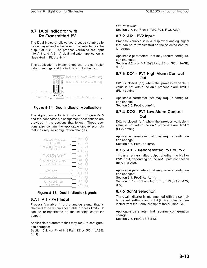
8.7 Dual Indicator with Re-Transmitted PVThe Dual Indicator allows two process variables tobe displayed and either one to be selected as theoutput at AO1. The process variables are inputinto AI1 and AI2. A dual indicator application isillustrated in Figure 8-14.
This application is implemented with the controllerdefault settings and the in.Ld control scheme.
Figure 8-14. Dual Indicator Application
The signal connector is illustrated in Figure 8-15and the connector pin assignment descriptions areprovided in the sections that follow. These sec-tions also contain the applicable display promptsthat may require configuration changes.
Figure 8-15. Dual Indicator Signals
8.7.1 AI1 - PV1 InputProcess Variable 1 is the analog signal that ischecked to be within acceptable process limits. Itcan be re-transmitted as the selected controlleroutput.
Applicable parameters that may require configura-tion changes:Section 5.2, conF- Ai.1-(SPan, ZEro, SQrt, bASE,dFLt).
For PV alarms:Section 7.7, conF-cn.1-(AiX, PL1, PL2, Adb).
8.7.2 AI2 - PV2 InputProcess Variable 2 is a displayed analog signalthat can be re-transmitted as the selected control-ler output.
Applicable parameters that may require configura-tion changes:Section 5.2, conF-Ai.2-(SPan, ZEro, SQrt, bASE,dFLt).
8.7.3 DO1 - PV1 High Alarm Contact OutD01 is closed (on) when the process variable 1value is not within the cn.1 process alarm limit 1(PL1) setting.
Applicable parameter that may require configura-tion change:Section 5.6, ProG-do-inV1.
8.7.4 DO2 - PV1 Low Alarm Contact OutD02 is closed (on) when the process variable 1value is not within the cn.1 process alarm limit 2(PL2) setting.
Applicable parameter that may require configura-tion change:Section 5.6, ProG-do-inV2.
8.7.5 A01 - Retransmitted PV1 or PV2This is a re-transmitted output of either the PV1 orPV2 input, depending on the Ao1.i path connection(to Ai1 or Ai2).
Applicable parameters that may require configura-tion changes:Section 5.4, ProG-Ao-Ao1.i.Section 7.7 - conF-cn.1-(oh, oL, hML, oSr, rSW,rSV).
8.7.6 SchM SelectionThe dual indicator is implemented with the control-ler default settings and in.Ld (indicator/loader) se-lected from the SchM prompt of the cS module.
Applicable parameter that requires configurationchange:Section 7.6, ProG-cS-SchM.
Section 8. Eight Control Strategies 53SL6000 Instruction Manual
8-13

8.8 Proportional Speed Floating ControlThis control output is suitable for any of the controlschemes where the final control element is usuallya motorized valve. The controller output is pro-vided at two discrete outputs, rather than the ana-log output AO1. One discrete output drives themotor in one direction and the other discrete outputdrives the motor in the opposite direction. The MS1and MS2 indicators activate, depending on the DOdriving the motor. The discrete output logic assertsfor a period of time that is proportional to the quan-titative requirement of the corrective action. Thegreater the error, the longer the discrete outputlogic will be asserted. If the deviation is zero andthere is no signal on either discrete output, themotor can be at any position within its operatingrange; therefore, the motorized valve is said to befloating. Since the motorized valved is moved at aspeed proportional to the deviation, and floatswhen there is no output signal, this output type iscalled proportional speed floating control.
8.8.1 Motorized Valve ConnectionsThe 2DI/2DO option module is required for propor-tional speed floating control because the standarddiscrete outputs DO1 and DO2 do not have relays.It is NOT recommended that DO1 and DO2 beused for this output application, as doing sowould require a motor interface (e.g., relays ortriac circuitry). An illustration of proportionalspeed floating control output is provided in Figure8-16. Also shown in the illustration are the wiringconnections at the 2DI/2DO module connectorTB2. The motor connections are not shown due toproduct variations. The user must ascertain howthe leads are connected at the motor to cause it todrive in the required direction for each active out-put.
8.8.2 Configuration RequirementsParameter inputs and path connections are re-quired to initiate proportional speed floating con-trol. The parameters affected apply only to controlmodule 1 (cn.1) of the conF menu and not controlmodule 2 (cn.2). The applicable path connectionsand parameter entries are as follows:
Figure 8-16. Proportional Speed FloatingControl
Switch path connections (these switches canbe found in the cS module of the ProG menu):
• ProG-do-do3.i should be at its default connec-tion to Vup.
• ProG-do-do4.i should be at its default connec-tion to Vdn.
• ProG-cS-doFb should be set to on if a valveslide wire is to be used.
• ProG-cS-cs.F should be connected to Ai.2.This allows the slide wire feedback (see Figure8-16) at Ai2 to be displayed in the yellow dro.The value displayed is in percent of the valveposition and not percent output. This is anoptional connection because some valves donot provide slide wire output.
Parameter entries:• Zero-out Manual Rest (conF-cn.1-Mr). Allow
full control range by setting output low-limit(conF-cn.1-oL) to -100 and output high-limit(conF-cn.1-oh) to 100.
• Enter an output duty cycle value in seconds inconF-cn.1-dcp. This value specifies, in sec-onds, the length of the cycle period over whichthe digital outputs VuP and Vdn are calculated.This time must be set based on the charac-teristics of the final control element and theamount of cycling permitted. A shorter dcpincreases motor cycling and a longer dcp de-creases motor cycling, which slows the controlresponse. For minimum cycling of the final
53SL6000 Instruction Manual Section 8. Eight Control Strategies
8-14

control element, the period should be set tomatch the end-to-end travel time of the ele-ment. To operate the digital outputs in a timeproportioning manner, much shorter cycletimes are required. Because each cycle periodis divided into 0.05 second pieces, the resolu-tion of the output is determined by the length ofthe cycle period.
For example: If dcP is 10 seconds, then theperiod will contain 200 pieces (10/0.05 = 200),each being 0.5% of the 10 second period. Ifthe controller output (OUT) value is 27.65 (%)at the start of the period, then the VuP logic willremain a "1" for 2.8 seconds (27.65% roundedto the closest 0.5% = 28.1 or 28%; 0.28 x 10seconds = 2.8 seconds). 2.8 seconds isequivalent to 56 pieces. The cycle period willbe a "0" for the remainder of the period, whichis 7.2 seconds (144 pieces). The dcp valueaffects the discrete output pulse repitition fre-quency. A dcp of 0 turns off VuP and Vdn.
• Enter a minimum manual time in conF-cn.1-MMt. This value designates the mode of man-ual operation associated with the VuP and Vdnlogic signals. When MMt = 0, VuP and Vdn arealways a pulse width modulated (PWM) repre-sentation of the control OUT signal. The PWMperiod is determined by the dcP parameter.When MMt = non-zero, VuP and Vdn are PWMrepresentations in automatic operation; how-ever, in manual operation, they are only activewhen either the of the output push buttons ispressed. A non-zero value entered for MMtrepresents in percent the minimum duty cycleperiod the logic values VuP and Vdn will be a 1whenever the output push buttons are momen-tarily depressed or when a networked devicegenerates an associated push button opera-tion.
Non-zero operation:
OUTPB
VuP
dcP
Sec.
0 1 2 3 4 25 26 27 28 29 30
dcP = 30 seconds
MMt (MMt = 5% dcP)
• Enter a value into conF-cn.1-Pb between 0.02and 1000. The %Pb is determined from thespeed factor, which is calculated as follows:
Speed Factor =
% input deviation% output duty cycle
X 100
or Speed Factor = % deviation required for maximum motor speed.
Because the controller operates as a devia-tion-to-duty cycle converter and the motorizedcontrol valve provides the integral action, thetotal integral gain depends not only on the con-troller Pb setting but also on the speed of thevalve. Integral gain is expressed as follows:
Integral Gain =
Speed Factor of Controllerfull stroke travel t ime of valve in seconds
• Enter a control zone value to reduce motorhunting in conF-cn.1-cZ. The peak-to-peakvalue of noise or fluctuation of the processsignal must be smaller than the control zonefor stable operation. A control zone as wide aspossible should be entered to extend the serv-ice life of the motorized valve operator.
• Select the desired controller output-to-processvariable relationship (dir/rEV) with conF-cn.1-rSW.
• Scale the slide wire analog input 2 signal withconF-cn.2-(SPAn, ZEro) as follows:
The limit switches in the valve operator shouldbe properly adjusted. Refer to the appropriatemanufacturer’s instructions for details. Inmanual operation, depress and hold the con-troller’s increase output or decrease outputpush button. Check that the final control ele-ment operates in the proper direction and thatthe slide wire valve indicator (yellow dro)moves in the proper direction (0% representsfully closed, 100% represents fully open). En-sure the valve indicator tracks the valve posi-tion.
Drive the valve fully closed and adjust the Ai.2module conF-cn.2-ZEro parameter for 0% me-ter position.
Drive the valve fully open and adjust the Ai.2module conF-cn.2-SPAn parameter for 100%meter position.
Section 8. Eight Control Strategies 53SL6000 Instruction Manual
8-15
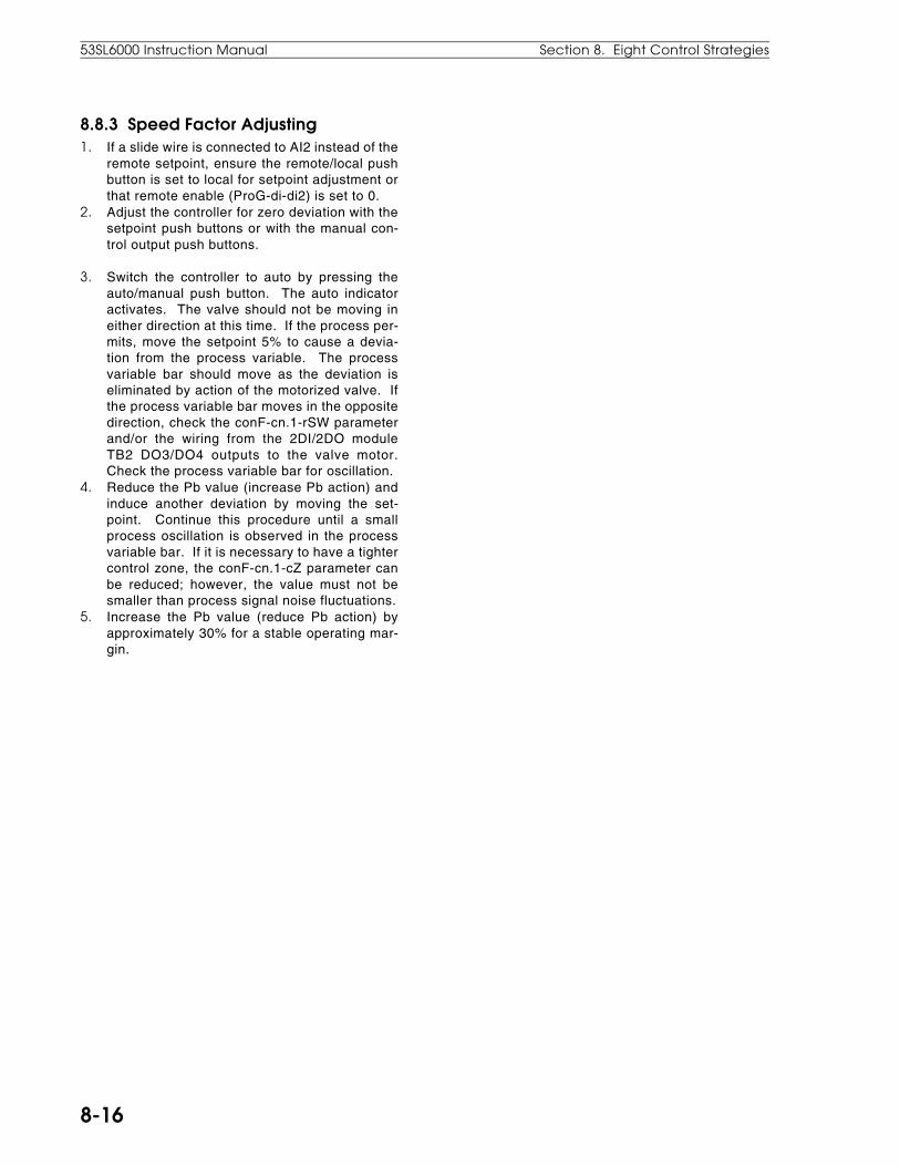
8.8.3 Speed Factor Adjusting1. If a slide wire is connected to AI2 instead of the
remote setpoint, ensure the remote/local pushbutton is set to local for setpoint adjustment orthat remote enable (ProG-di-di2) is set to 0.
2. Adjust the controller for zero deviation with thesetpoint push buttons or with the manual con-trol output push buttons.
3. Switch the controller to auto by pressing theauto/manual push button. The auto indicatoractivates. The valve should not be moving ineither direction at this time. If the process per-mits, move the setpoint 5% to cause a devia-tion from the process variable. The processvariable bar should move as the deviation iseliminated by action of the motorized valve. Ifthe process variable bar moves in the oppositedirection, check the conF-cn.1-rSW parameterand/or the wiring from the 2DI/2DO moduleTB2 DO3/DO4 outputs to the valve motor.Check the process variable bar for oscillation.
4. Reduce the Pb value (increase Pb action) andinduce another deviation by moving the set-point. Continue this procedure until a smallprocess oscillation is observed in the processvariable bar. If it is necessary to have a tightercontrol zone, the conF-cn.1-cZ parameter canbe reduced; however, the value must not besmaller than process signal noise fluctuations.
5. Increase the Pb value (reduce Pb action) byapproximately 30% for a stable operating mar-gin.
53SL6000 Instruction Manual Section 8. Eight Control Strategies
8-16
9.1 OverviewCommissioning is an iterative process of refiningthe proportional band - Pb (Pb.2), integral or resettime - tr (tr.2), and derivative time - td (td.2) pa-rameter values for each active control module.Collectively, these three control action parametersare called the PID and can be accessed from theoPEr menu if they are enabled for display with theconF-OPr-Pid.E parameter or they can be ac-cessed from the conF-cn.1(cn.2) module. The val-ues entered for these three parameters aredependent upon the process application and de-sired controller response to disturbances. It is notnecessary to have all three parameters active forevery process application. If a control strategy isimplemented that uses both control modules (cn.1and cn.2), then the PID parameters for each controlmodule may require configuring.
9.2 Proportional Action (Pb)In proportional action (conF-cn.1[cn.2]-Pb) there isa comparative relationship between the controlleroutput signal magnitude and the calculated error,which is the difference between the measuredprocess variable feedback and the desired set-point. The proportional action of the controller isset as a percentage of the proportional band (%PB)from 2% to 1000%. If the %PB (Pb) is set at 2%, asmall percent change in error causes full scale out-put signal magnitude (narrow proportional band).Conversely, If the %PB (Pb) is set at 1000%, alarge percent change in error causes full scale out-put signal magnitude (wide proportional band).
Because it is the process itself that provides thefeedback as the process variable, the controlleroutput must be correctly spanned to the maxi-mum/minimum swing of the process control ele-ment, and it is assumed the output signal sent tothe the process control element will positionallyalter it to null the calculated deviation error.
Process dynamics can therefore adversely affectcorrect process control element positioning. Forexample, two process disturbances that cause the same calculated deviation error will not necessarilycause a repositioning of the process control ele-ment. As shown in the table, Disturbance 1 causedan error of 3. The process control element positionwas changed to overcome the error and restore PVback to setpoint, but the cause of the disturbancewas not removed; therefore, the controller output
must remain at its new position to keep the PV at10. With disturbance 2, an error of identical magni-tude (3) is created; the process control element willnot move because it is already resting at itsspanned value for that output signal level eventhough the process has not been restored to thedesired setpoint of 10. The cumulative effect onprocess control of this inherent deficiency of pro-portional action is called offset error (off from set-point).
Disturbance SP PV Error Output Actionquiescent 10 10 0 no
changenone
1 10 7 3 newvalue
changeprocesscontrol
elementposition
quiescent 10 10 0 same asfor 1
none
2 10 7 3 same asfor 1
none
If offset error occurs within a tolerable range, it canbe ignored; if it occurs as an unacceptable valuewith ± tolerable variances, it can be countered withmanual reset (Mr). There is an Mr prompt that thatcan be accessed from each control module, cn.1 orcn.2. Manual reset is entered as a value from 0%to 100% output to compensate for the deviationfrom setpoint that proportional action can not elimi-nate. Because manual reset is entered as a fixedvalue, it is limited with respect to process dynam-ics. An alternative to manual reset is integral ac-tion (tr).
9.3 Integral Action (tr)Integral action (conF-cn.1[cn.2]-tr) augments pro-portional action to cause the controller to drive theprocess control element until the process deviationis nulled. It is sometimes called reset, whichmeans return to setpoint. Integral action producesa signal value that is a function of the deviationfrom setpoint and the %PB setting. For example, ifsetpoint was at 500°F and the controlled processtemperature dropped down to 400°F, there wouldbe a 100°F deviation. If %PB had been set at 10%,then the integral action in the first repetition intervalwould be 10% x 100° or 0.1 x 100° = 10°. Theprocess control element would be moved until tem-perature increased an additional 10° from 400° to410°. In the second repetition interval, integral ac-tion would be 10% x 90° or 0.1 x 90° = 9°. The
9.0 Commissioning
Section 9. Commissioning 53SL6000 Instruction Manual
9-1

process control element would be moved until tem-perature increased an additional 9° from 410° to419°. Integral action would continue at each repe-tition interval until setpoint was reached. In thisway integral action sneaks-up on setpoint. Thetime between repetition intervals can be set from0.02 minutes/repeat (maximum integral action) to200 minutes/repeat (minimum integral action); 0 isoff.
9.4 Derivative Action (td)Derivative action (conF-cn.1[cn.2]-td) is used forquick attainment of stability after sudden processdisturbances. It augments proportional action byresponding to the rate of change of the processvariable. If the error does not change, the output isproportional only. The rate of change is the incre-mental difference in the error with respect to anincremental amount of time, which is the slope (riseover run) of the error. Derivative action is enteredas time from a minimum value of 0.01 minutes to amaximum value of 8 minutes; 0 is off.
9.5 Trial and Error Tuning MethodThe trial and error tuning method is usually pre-ferred for process loops that respond quickly, re-quiring no waiting to determine steady cyclingprocess conditions. The steps to perform the trialand error tuning method are as follows:
1. Set the process to approximately normal condi-tions with the controller in manual mode.
2. Set the integral parameter conF-cn.1(cn.2)-trfirst to 0.02 for several moments, then set it to200 to lock in a fixed reset value.
3. Set the proportional band parameter conF-cn.1(cn.2)-Pb to 1000.
4. Set the derivative parameter conF-cn.1(cn.2)-td to 0.01.
5. Switch to auto mode.6. Slowly reduce the proportional band parameter
conF-cn.1(cn.2)-Pb from 1000 until process cy-cling starts.
7. Increase the der ivat ive parameter conF-cn.1(cn.2)-td slowly from 0.01 until process cy-cling stops.
8. Reduce the proportional band parameter conF-cn.1(cn.2)-Pb until process cycling startsagain.
9. Increase the der ivat ive parameter conF-cn.1(cn.2)-td again until cycling stops.
10. Repeat steps 8 and 9 until no improvement canbe made when the derivative parameeterconF-cn.1(cn.2)-td is increased.
11. Increase the proportional band parameterconF-cn.1(cn.2)-Pb to a safe margin approxi-
mately 1.5 times the value attained in steps 8through 10.
12. Introduce integral action slowly by decreasingthe conF-cn.1(cn.2)-tr parameter until cyclingstarts.
13. B ack o f f t he in tegra l parame te r conF -cn.1(cn.2)-tr to a safe margin about 1.5 timesthe value attained in step 12.
9.6 Proportional Cycle Tuning MethodThe proportional cycle tuning method is an expedi-ent procedure for slow processes. The steps toperform this method are as follows:
1. Set the process to approximately normal condi-tions with the controller in manual mode.
2. Set the integral parameter conF-cn.1(cn.2)-trfirst to 0.02 for several moments, then set it to200 to lock in a fixed reset value.
3. Set the proportional band parameter conF-cn.1(cn.2)-Pb to 1000.
4. Set the derivative parameter conF-cn.1(cn.2)-td to 0.01.
5. Switch to auto mode.6. Slowly reduce the proportional band parameter
conF-cn.1(cn.2)-Pb from 1000 until process cy-cling starts.
7. When a slight cycle is repeatedly established,measure the peak-to-peak period of oscillationand record it as T minutes.
8. Observe the proportional band parameterconF-cn.1(cn.2)-Pb setting and record it as P.
9. Using the multipliers provided, compute thebest settings as follows:
• Proportional and integral (PI): Pb = 2P; tr= 0.8T.
• Proportional and derivative (PD): Pb =0.8P; td = 0.12T.
• Proport ional, integral, and derivative(PID): Pb = 1.5P; tr = 0.5T; td = 0.12T.
9.7 Step Response Tuning Method (Ziegler-Nichols)The step response tuning method is another expe-dient procedure for slow processes. The step re-sponse tuning curve is illustrated in Figure 9-1 andthe steps to perform this method are as follows:
1. Set the process to approximately normal condi-tions with the controller in manual mode.
2. Introduce a 10% (approximate) step change tothe controller output signal. Observe the mag-
53SL6000 Instruction Manual Section 9. Commissioning
9-2

nitude of the step in percent of full signal spanA. Also plot a graph of the resulting transientcurve traced by the controlled variable.
3. Draw a straight line tangent to a point on thecurve having the greatest slope (most linear).
4. Measure the apparent dead time Wp in min-utes as shown in Figure 9-1.
5. Measure Tp, the product of the slope and deadtime as shown in Figure 9-1. This value shouldbe expressed in percent of full scale span.
6. Using the multipliers provided, compute thebest settings as follows:
• Proportional (P): Pb = (100Tp)/A.
• Proportional and integral (PI): Pb = (100Tp)/A; tr = 3Wp.
• Proport ional, integral, and derivative(PID): Pb = (80Tp)/A; tr = 2Wp; td =0.5Wp.
Figure 9-1. Typical Step Response Record
9.8 Easy-TuneThe Easy-Tune algorithm approximates a first or-der time lag with gain and dead-time to determinethe optimal PID characteristic constants. TheEasy-Tune sequence is graphically illustrated inFigure 9-2. In the figure, the first step change isused to calculate a preliminary estimate of the firstorder time lag (Tp) and the dead-time (Wp) bybuilding an approximated process step responsecurve model. Detailed illustrations of this approxi-mation are shown in Figures 9-3 and 9-4. Thesecond step change, shown in Figure 9-2, is usedto calculate the process gain (Kp) measured as theproportionality between the output step change andprocess response. Using the same techniques il-lustrated in Figures 9-3 and 9-4, the final estimatesfor the time lag (Tp) and dead-time (Wp) values are
also made as the process step response curvedecays after the second step change is removed.The values for Tp, Wp, and Kp, are then applied tothe ITAE (Integral Time Absolute Error) equationsgiven in Table 9-1. The equation results can bepreviewed or allowed to be automatically enteredinto the tuning constants P, I, D for the selectedloop. Values entered into the tuning constants arelimited to controller specifications as follows:
Proportional (EPb) 1000 - 2Integral (Etr) 200 - 0.02, 0 (off)Derivative (Etd) 8 - 0.01, 0 (off)
Before executing Easy-Tune the following must beconsidered:
1. For slow processes, be sure the process vari-able is steady before executing Easy-Tune.
2. Disturbance of the process during Easy-Tuneexecution may result in a false process charac-terization.
3. Feed forward control must be OFF.4. If the ratio of process dead-time Wp and the
process time lag Tp is greater than 0.5, it isrecommended that the PID control mode beused (e.g., cM = PID in Table 9-2).
5. Processes that act as pure integrators can notbe tuned by Easy-Tune because those proc-esses have no self regulation, as only onevalue of the controller output is able to cause asteady state process.
6. In rare cases, a process response may not besatisfactorily approximated as a first order timelag with gain and dead-time.
Table 9-1. ITAE EquationsMode Action Equation
P PB in %204K p ( Wp
Tp ) 1.084
TR (Min) 0TD (Min) 0
PI PB in % 116.4 Kp (Wp
Tp ) 0.977
TR (Min) Tp40.44
( Wp
Tp ) 0.68
TD (Min) 0PID PB in % 73.69 Kp ( Wp
Tp ) 0.947
TR (Min) Tp51.02
( Wp
Tp ) 0.738
TD (Min) Tp157.5
( Wp
Tp ) 0.995
PD* PB in % 54.38 Kp ( Wp
Tp ) 0.947
TR (Min) 0TD (Min) Tp
157.5 ( Wp
Tp ) 0.995
*Empirical estimates not based on ITAE method.
Section 9. Commissioning 53SL6000 Instruction Manual
9-3

Figure 9-2. Easy-Tune Process
Figure 9-3. Preliminary Step Response -Actual Curve
Figure 9-4. Preliminary Step Response - Approximated Curve
53SL6000 Instruction Manual Section 9. Commissioning
9-4

9.8.1 Executing Easy-TuneEasy-Tune is executed from the conF-EZ moduleparameters. A typical controller display illustratingEasy-Tune being executed is provided in Figure9-5. Easy-Tune execution can be aborted at anytime by first pressing either output push button andthen by pressing the mode/select push button. Af-ter the output push button is pressed, outX appearsin the SP dro and the Easy-Tune LED remains onbut stops blinking.
NOTE 1: For two loop cascade (cASc) controlschemes, the loop to be tuned is selected inoperator mode as the displayed loop beforeexecuting Easy-Tune.
Also, in a cascade control scheme, loop 1(secondary) is tuned first to the desired responsecharacteristics. It is then set to automatic with theremote setpoint enabled before loop 2 (primary) isselected and tuned.
The general rule for tuning cascade control is thatthe secondary loop (loop 1) must be tuned tighterand faster than the primary loop (loop 2);otherwise, the setpoint of the secondary, whichcomes from the primary, would vary more than thesecondary’s process variable, resulting in poorcontrol of the primary loop.
The secondary process variable should notovershoot the input setpoint from the primary bymore than 5 percent.
After the secondary is tuned, ensure the tunedvalues conF-cn.1-Pb, conF-cn.1-tr, andconF-cn.1-td are entered before the primary loop(conF-cn.2-[Pb, tr, td]) is tuned.
The primary loop is selected in operator modebefore Easy-Tune is executed.
NOTE 2: For two loop high limit/low limit(h.LiM/L.LiM) control schemes, the loop to betuned is selected in operator mode as thedisplayed loop before executing Easy-Tune.
To tune loop 1 (primary), of a high/low limitscheme, loop 2 (limiting) is set so that the outputchanges used to tune loop 1 do not cause theloop 2 limiting controller to modify the outputvalue, as this will give erroneous results. Whentuning loop 1 (primary) the hard manual limitparameter conF-cn.1-hML is set to off.
To tune loop 2 (limiting) of a high/low limitingscheme, the loop 2 (limiting) output is manuallyadjusted to the desired process limiting value andthe loop 1 (primary) display is then selected inoperator mode and set to automatic. Thecontroller is placed in local and the setpoint pushbuttons are used to move the loop 1 (primary)setpoint to the extreme end of the instrumentrange, either to the high end for high limiter or thelow end for low limiter. This setpoint valueensures the loop 2 (limiting) output value plus theDOUT +/- output step change value induced byEasy-Tune do not interact with the setpoint. Ineffect loop 1 (primary) is decoupled.
The steps to execute Easy-Tune are as follows:
1. Press and hold the mode/select pb to enterengineering mode.
2. Press the scroll forward pb until the conFprompt appears in the green dro.
3. Press the select pb.4. Press the scroll forward pb until the EZ prompt
appears in the yellow dro.5. Press the select pb; the first parameter prompt
(cM) appears in the green dro (it replacesconF), and its value (P) appears in the red dro.
6. Press the select pb; the value in the red drostarts blinking.
7. Press the scroll forward pb to alter/edit the reddro value.
8. Press the select pb to enter the value.9. Repeat steps 5 through 8 to alter the remaining
parameters listed in Table 9-2. Selecting YeSto the run? prompt, which is the last parameterin Table 9-2, causes Easy-Tune to start exe-cuting.
Section 9. Commissioning 53SL6000 Instruction Manual
9-5

Figure 9-5. Easy-Tune Display
53SL6000 Instruction Manual Section 9. Commissioning
9-6

Table 9-2. Easy-Tune Parameters
conF → EZPrompt Description DftcM Control Mode
Select the desired control action(s) forthe process: P, PI, PID, PDIf previous Easy-Tune results indicatedthe ratio of process dead time - Wp(WP) to the process time lag - Tp (tP)was greater than 0.5, then PID shouldbe selected for control mode.
P
tLiM Limiting Settling TimeIt is set to the time in seconds allowedfor the process to settle and the pre-liminary step response to be detected.
0.0
dPV PV Excursion LimitIt is a percentage entered as a nu-meric value that prevents excessivechanges in PV.
0.0
dout Output Step It is set to the size of the outputchange in percent that is used duringthe tuning operation. This value canbe positive or negative, dependingon the direction of the output changeselected with the reverse parameter(conF-cn.1-rSV). The value enteredshould be large enough to causesignificant, but allowable PV changesin the process.
0.0
dPPV Preliminary PV Step DisturbanceIt is set to the change in PV requiredto complete the preliminary stepoperation. This value should beapproximately 1/4 th the expectedchange caused by the setting ofdout. (This value is not 1/4 th of doutbecause the expected PV change isdependent upon process gain anddout.)
2.0
PLiM Parameter Modify Selecting on allows Easy-Tune tomodify the characterization values ina conservative direction: that is,overshoot is reduced compared tocontrol operation using the ITAEcalculated values.
oFF
APLd Automatic Tuning Parameter EntryThe default, oFF, indicates thecalculated tuning values forparameters conF-cn.1(cn.2)-Pb, tr,and td will not be automaticallyentered, but available for review inconF-EZ-EPb, Etr, and Etd (see Section9.8.2, Easy-Tune Determined Values).Change to on for automatic entry.
oFF
Table 9-2. Easy-Tune Parameters
conF → EZPrompt Description Dftrun? Run Select
During execution, the Easy-Tune LEDflashes and tunE appears in the greendro. Upon successful completion, theEasy-Tune LED stops flashing and thegreen dro no longer displays the tunEmnemonic. If an error or warningcondition occurs during execution,the Easy-Tune LED changes to asteady-state-on condition and amnemonic is displayed in the greendro that identifies the error or warning.Pressing the mode/select push buttonclears the display. After taking theappropriate corrective action(s), Easy-Tune can be restarted by selectingYeS at the run? prompt in the EZ menu.
no
9.8.2 Easy-Tune Determined ValuesThe Easy-Tune calculated values can be viewed atthe prompts listed in Table 9-3. If conF-EZ-APLd(in Table 9-2) was left at the default value (oFF),then conF-EZ-EPb, Etr, and Etd values will not beautomatically written into the PID constants.
Table 9-3. Easy-Tune Determined ValuesconF → EZ
Prompt Description DftKP Easy-Tune calculated gain. 0.0tP Easy-Tune calculated first order time
constant.0.0
WP Easy-Tune calculated dead-time. 0.0EPb Resultant %PB value calculated by
Easy-Tune.0.0
Etr Resultant reset time value calculatedby Easy-Tune.
0.0
Etd Resultant derivative time valuecalculated by Easy-Tune.
0.0
9.8.3 Easy-Tune Status ResponsesIf Easy-Tune responds with an error or warningcondition during execution, the tune LED changesfrom a flashing to a steady-state-on condition and amnemonic appears in the green dro that identifiesthe error or warning.
The Easy-Tune responses are provided in the sec-tions that follow. After taking the appropriate cor-rective action(s) for the error or warninig condition,Easy-Tune can be restarted by selecting YeS at therun? prompt in the EZ menu.
Section 9. Commissioning 53SL6000 Instruction Manual
9-7
9.8.3.1 out ResponseThis response indicates the controller output wasinitially at extreme maximum or minimum when thepreliminary step change was attempted. Restorethe controller operating band to mid-range; if thecontroller must operate at saturated output, thenEasy-Tune can not be successfully executed.
9.8.3.2 dout ResponseThis response indicates saturation would have oc-curred if Easy-Tune had continued. Reverse thesign of the step size configured into dout and exe-cute Easy-Tune again.
9.8.3.3 dPV ResponseThis response indicates PV excursion exceededthe limit specified in conF-EZ-dPV. Increase thelimit value specified in conF-EZ-dPV and executeEasy-Tune again.
9.8.3.4 outX ResponseThis response indicates the controller output wasinadvertently altered. Refrain from altering control-ler output during Easy-Tune execution.
9.8.3.5 StiM ResponseThis response indicates A time-out occurred duringinitial settling. Process settling was not detectedduring the time interval specified in conF-EZ-tLiM.
9.8.3.6 PtiM ResponseThis response indicates a time-out occurred duringthe preliminary step change. The preliminary stepchange could not complete in the time intervalspecified in conF-EZ-tLiM. Increase the conF-EZ-tLiM value or decrease the dPPV value.
9.8.3.7 WtiM ResponseThis response indicates a time-out occurred duringthe preliminary estimate of Tp and Wp. A distur-bance might have occurred during Easy-Tune exe-cution causing the preliminary step excursion toextend beyond the time limit of 20 step change timeintervals (shown as limit = 20X in Figure 9-2).
9.8.3.8 KtiM ResponseThis response indicates a time-out occurred duringthe second step change. A disturbance might haveoccurred during Easy-Tune execution causing thesecond step change to extend beyond the approxi-mated time of 10 Tp’s and Wp’s (shown as limit =[2.5 Te + We][10] in Figure 9-2).
9.8.3.9 ttiM ResponseThis response indicates a time-out occurred duringthe decay of the second step change. A distur-bance might have occurred during Easy-Tune exe-cution causing the second step change decay to
extend beyond the approximated time of 10 Tp’sand Wp’s (shown as limit = [2.5 Te + We][10] inFigure 9-2).
9.8.3.10 Abrt ResponseThis response indicates an intentional abort wasperformed at the datalink host.
9.8.3.11 PidL ResponseThis response indicates a tuning parameter limitwas exceeded (e.g. exceeded 8 for conF-EZ-Etd)during the execution of Easy-Tune. This is only awarning, Easy-Tune completed execution and thePID parameters were loaded as specified by conF-EZ-APLd.
9.8.3.12 cM ResponseThis response indicates the selected tuning controlmode is illegal. Check conF-EZ-cM to see if P, PI,PID, or D is selected.
9.8.3.13 cASc ResponseThis response indicates an illegal control mode(conF-EZ-cM) is selected in the master or secon-dary.
9.8.3.14 oVr ResponseThis response indicates the loop being tuned isbeing overriden by the other loop. See note 2 inSection 9.8.1.
53SL6000 Instruction Manual Section 9. Commissioning
9-8

AdditiveFeedForward(FF)
This analog input signal isadded to the PID result toform the control scheme out-put value when auto opera-tion is active.
AnalogBack-upControl
A control strategy wherebythe controller acts as an auto-matic back-up device in theevent a host computor con-trolling the process fails. Thiscont ro l s t ra tegy is imple-mented with the factory de-fault settings, by selecting theSnGL prompt for the ProG-cS-SchM parameter, and withpath connect ions used todrive the final element outputselector.
AnalogInput (AI)
An input that accepts a 0-20mA or a 4-20 mA signal. The53SL6000 controller has twostandard analog inputs andcan accept two optional ana-log inputs via the universalanalog input module.
AnalogInputRegister(Ai)
Analog input registers 1-4 re-ceive their hardware inputanalog values after signalconditioning has been appliedto the analog inputs 1-4.(Hardware input to analog in-puts 3 and 4 requires the op-tional universal analog inputmodule.) Constant valuescan be entered into all of theanalog registers 1-8; how-ever, if the register has an ac-t i v e ha rdw are i npu t , t heconstant value will be over-written.
AnalogOutput (AO)
A standard 0-20 mA or 4-20mA analog signal is trans-m i t t e d b y t h e c o n t r o l l e rthrough analog output 1. It isdefined as a percent of outputvalue (percent of final controlelement excursion from mini-mum to maximum).
Auto/ManualSelector
A control strategy wherebythe controller acts as a signalpass-through device when inauto, w i th capab i l i t ies tomanually provide a controloutput i f necessary. Thiscont ro l s t ra tegy is imple-mented in the 53SL6000 con-troller with the factory defaultsettings and by selecting thein.Ld prompt for the ProG-cS-SchM parameter.
BarorVerticalBar
An LED ladder used to dis-play percent. The 53SL6000controller has two verticalbars , each conta in ing 40LEDs: red, which is used pri-marily to display the processvariable; and green, which isused primarily to display thesetpoint.
Characterizer A 53SL6000 functional unitthat provides signal valuemodification via any one offour operating modes: thirdorder polynomial, twelve seg-ment l inear , setpoint pro-g r ammer , and d ig i t a l - to -analog converter.
Controller Refers to the 53SL6000 con-trol uni t descr ibed in thismanual. Primarily, it is a de-vice used to maintain processquiescence at a predeter-mined setpoint level.
ControlScheme
The control scheme is thefundamenta l funct ional i tyneeded to calculate and pro-duce the necessary outputcontrol signal. There are fivecontrol schemes provided inthe 53SL6000 controller thatcan be used as the basis formany con t r o l s t r a teg ies .Each control scheme appliesto a unique area of processcontrol:
SnGL - for control strategies
Appendix A: Glossary
Appendix A. Glossary 53SL6000 Instruction Manual
A-1
requiring standard single loopfunctionality.
cASc - for control strategiesrequiring cascade functional-ity.
L.LiM - for control strategiesrequiring low limiting function-ality.
h.LiM - for control strategiesrequiring high limiting func-tionality.
in.Ld - for control strategiesrequ i r ing ind icator / loaderfunctionality.
ControlStrategy
A 53SL6000 controller modeof operation specified with aselected control scheme, pa-rameters, and path connec-tions designed to meet thespecific application needs ofa controlled process.
DerivativeAction (td)
Derivative action (td) is usedfor quick attainment of stabil-ity after sudden process dis-t u r b an ce s . I t au gmen tsproport ional act ion by re-s p o n d i n g t o t h e r a t e o fchange of the process vari-able. Derivative action is en-tered as the time proportionalaction is advanced, from 0.01minutes (minimum action) to8 minutes (maximum action);0 is off.
DigitalRead-Out(dro)
An LED field used to displaya l p h a n u m e r i c s . T h e53SL6000 con t ro l le r hasthree dros: red, which is afour character field used pri-marily for the process vari-able value in engineer ingunits; green, which is a fourcharacter field used primarilyfor the setpoint value in engi-neering units; and yellow,which is a three characterfield used primarily for theoutput value expressed as apercentage of the final controlelement excursion or operat-ing band.
Digital-to-AnalogConverterMode
An operating mode of thecharacterizer whereby valuesare entered into chr parame-ter constants K1 and K2,which are used as multipliersfor the digital inputs at chr.band chr.c respectively. Thep roduc t o f ( ch r .b ) (K1) i sadded to the characterizerbase va lue (no t user ac-cessable) and the product of(chr.c)(K2) is subtracted fromthe characterizer base value.It is the interaction of thesetwo inputs, chr.b and chr.c onthe base that causes the ana-log output
DiscreteInput (DI)
Discrete inputs 1-4 are inputenables that can also be usedas event indicators to gener-ate logic levels based on theapplied input voltage. (Dis-crete inputs 3 and 4 requirethe 2DI/2DO option module.)The remainder of the discreteinputs 5-8 do not receive in-puts from external sources.
DiscreteOutput (DO)
Discrete outputs 1-4 convertlogic levels to hardware con-tact condit ions. (Discreteoutputs 3 and 4 require theoptional 2DI/2DO module.)The remainder of the discreteoutputs 5-8 do not provide ex-ternal outputs from the con-troller.
DisplayPanel
The 53SL6000 con t ro l le rfunctionality for the faceplatepush buttons and LEDs.
DualIndicator withRe-TransmittedProcessVariable
A control strategy wherebytwo analog inputs can be dis-played and either one can beselected as the re-transmittedoutput. This control strategyis implemented with the fac-tory default settings and byselecting the in.Ld prompt forProG-cS-SchM parameter.
Easy-Tune The 53SL6000 con t ro l le rautomatic tuning algorithmthat approximates a first or-der time lag with gain anddead-time to determine the
53SL6000 Instruction Manual Appendix A. Glossary
A-2
opt imal PID character isticconstants.
Faceplate The entire visable front of thecontroller casework that con-tains the push buttons andLEDs.
FinalControlElement
The actual device used to al-ter the process medium (e.g.,flow, heat, gas density, etc.)level under control.
IntegralAction (tr)
Integral action (tr) produces avalue that is a function of thedeviation from setpoint andthe %PB setting. It augmentsproportional action to drivethe process final control ele-ment until the deviation isnulled. Integral action is setas the time between repititioni n t e r v a l s f r om 0 .02 m in-utes/repeat (maximum action)to 200 minutes/repeat (mini-mum action); 0 is off.
LightEmittingDiode(LED)
A diode that emits photon en-ergy in response to electricalimpulses. In the 53SL6000controller, an LED can beused as an indicator, in whichcase it appears on the displayas a single light point source(e.g., the "1" LED on the dis-play that indicates loop 1when active); or LEDs can begrouped together for a spe-cific function (e.g., each char-acter position of a dro hasseven LEDs that are availableto create the displayed char-acter and one LED for thedecimal point).
LogicBlock
A logic block can perform anyone of eight Boolean func-tions on two inputs. The func-tions are: A OR B, A AND B,A XOR B, A OR NOT B, AAND NOT B, NOT A OR B,NOT A AND B, and NOT AXOR B. There are four logicblocks in the 53SL6000 con-troller as part of the discreteinput/output decision path.As determined by path con-nection capabilities, two of
the logic blocks are primarilyfor the discrete inputs (DIs)and two are for the discreteoutputs (DOs). The discreteoutput logic blocks can beconnected with path selec-tions to accept logic decisionsfrom the discrete input logicblocks.
LoopControlwithRemoteSetpoint
A control strategy whereby acontinuous analog output sig-nal or discrete output logicsignals are calculated basedon the difference between aprocess variable input and asetpoint. The setpoint can beset locally or received from aremote source. This controlstrategy is implemented in the53SL6000 controller with thefactory default settings andby selecting the SnGL promptfor the ProG-cS-SchM pa-rameter.
Math FunctionBlock
The math function block pro-vides nine different equationscapable of computing from amaximum of six Fnc parame-ter constants (K1-K6) andfour analog inputs (A-D) toproduce an augmented ana-log output. A logic output isalso provided as a state indi-cator for the limiter equations.It can also accept two logicinputs to choose any one offour selector equations.
Menu One of three prompts: oPEr,conF, and ProG that can beinvoked on the display in en-g i nee r mode. The oPErmenu provides operator ac-cess to commonly used pa-rameters that must first beenabled from the conF-oPrmodule. The conF and ProGmenus each provide a suite ofmodules that contain parame-ters used to configure control-ler operation.
Module An optional unit (e.g, RS-232module) that can be installedat the rear of the 53SL6000controller case.
Appendix A. Glossary 53SL6000 Instruction Manual
A-3

Also, a prompt that can be in-voked on the display in engi-neer mode (e.g., cn.1); i fselected, it provides scrollingcapabilities through a seriesof parameter prompts for con-figuration purposes.
Parameter One of many prompts subor-dinated to a selected moduleof the conF or ProG menus,or a prompt in the oPEr menu,that solicits configuration in-put. Configuring a parametermay require data to be en-tered, a YES/no choice to bemade, or a selection madefrom a list of items that ap-pear sequentially in the redd r o a s t h e s c r o l l f o r-ward/backward push buttonsare pressed.
Pass-Key Two pass-keys can be config-ured for the 53SL6000 con-troller. A pass-key is a fourdigit numeric value entered inthe red dro in response to thekey query to gain access toeither the conF menu or theP r o G m e n u i n e n g i n e e rmode.
PID A mnemonic that representsthe proportional, integral, andderivative actions caused bythe control scheme algorithmoutput.
ProcessVariable
The process feedback inputsignal provided by a measur-ing transmitter device that iscomputed against the control-ler setpoint to determine thedeviation error and requiredoutput to null the error.
Prompt An engineer mode alphanu-meric assigned to a menu,module, or parameter that ap-pears in a dro.
ProportionalAction (Pb)
Proportional action (Pb) pro-duces a value calculated fromthe difference between the
setpoint and process variablevalues. Proportional action isset as a percentage of theproportional band (%PB) from2% (narrow band - maximumaction) to 1000% (wide band -minimum action).
ProportionalSpeedFloatingControl
This t ime propor t ional orthree step output is applica-b l e t o a l l o f t h e c o n t r o lschemes. The controller out-put is provided as hardwarecontact levels from DO3 andDO4 that are proportional tothe quantitative requirementsof the corrective action. It isespecially useful for motor-ized control valves, wherebythe DO3 output drives thevalve in one direction and theDO4 output drives the valvein the opposite direction.
PushButton
Any one of seven tac t i leswitches on the 53SL6000controller faceplate used fordisplay panel operations.
RatioControl
A control strategy wherebythe control ler maintains aprocess variable in relation toa measured wild variable.This control strategy is imple-mented in the 53SL6000 con-troller with the factory defaultsettings, by selecting SnGLfor the ProG-cS-SchM pa-rameter, and by selectingK-SP for the setpoint modeparameter conF-cn.1-SPM.
RS-232Module
An option module that at-taches to the rear o f the53SL6000 controller case toprovide personal computerRS-232 COMM port connec-tivity.
RS-485Module
An option module that at-taches to the rear o f the53SL6000 controller case toprovide datalink connectivity.
Setpoint A displayed controller valuethat represents a desired qui-
53SL6000 Instruction Manual Appendix A. Glossary
A-4
escent process operat inglevel.
(Setpoint)ProgrammerMode
An operating mode of thecharacterizer that allows 13time intervals to be definedwith ProG-chr parameter con-stants K1-K13. Values en-te red in to chr parameterconstants K14-K26 are theramp values for each of thetime intervals.
SingleStationCascadeControl
A control strategy wherebythe controller response toprocess changes is enhancedby using two loops for an oth-erwise single loop applica-tion. The primary loop, whichcalculates a deviation outputfrom a slower respondingprocess provides the inputsetpoint to a secondary loop.The secondary loop calcu-lates a deviation output fromthe primary loop setpoint in-put and a process variablef rom a fas te r respondingprocess to alter the final con-trol element position. This inturn affects the slower re-sponding process and ulti-m a t e l y t h e p r im a r y l o opsetpoint output. Cascadecontrol is much tighter thansingle loop control, as the sin-gle loop would calculate a de-viation only from a predefinedsetpoint and a process vari-able from the slower respond-ing process. This controlstrategy is implemented in the53SL6000 controller with thefactory default settings andby select ing cASc for theProG-cS-SchM parameter.
SingleStationOverrideControl
A control strategy wherebytwo loops, primary and limit-ing, operate interdependentlyto control a final single ele-ment. With this strategy, nei-ther variable may exceed asafe limit. The primary loop
is in control unless its outputtries to exceed the high or lowlimit defined by the limitingloop. If the high limit is ex-ceeded, the controller will se-lec t the lower of the twooutput values (low override).If the low limit is exceeded,the controller will select thehigher of the two output val-ues (high override). The lowlimit control strategy is imple-mented with the factory de-fault settings and by selectingthe L.LiM for the ProG-cS-SchM parameter. The highlimit control strategy is imple-mented with the factory de-fault settings and by selectingthe h.LiM for the ProG-cS-SchM parameter.
Switch A symbol used in the controlscheme setpoint-deviation,PID, and output path illustra-tions that physically repre-sen ts a con tro l s ignal orpossible control scheme pa-rameter selection choices.
ThirdOrderPolynomialMode
An operating mode of thecharacterizer that provides amonotonically increasing in-dexing capability to five thirdorder polynomial equationsthat represent five adjacentsegments. Each segmentrepresents a defined control-ler output. Equation selectionis specified with the ProG-chr-K1 through K6 parame-ters and values entered intoProG-chr-K7 through K26 pa-rameter constants are the co-efficients A through D of thefive equations.
Tuning The iterative procedure offinding the optimal controllerPID (proportional, integral,and derivative) values as re-quired for the process undercontrol.
TwelveSegment
Appendix A. Glossary 53SL6000 Instruction Manual
A-5
LinearMode
An operating mode of thecharacterizer whereby valuesare entered into ProG-chr-K1through K26 parameter con-stants as 13 ordered pairs (Ainput, analog output) to spec-ify a 12 segment linear ap-proximation of the analoginput signal. Constants K1-K13 are the A input variables,and constants K14-K26 arethe analog output variables.Pairs are matched K1, K14;through K13, K26. The inputvariables must be monotoni-cally increasing.
2DI/2DOModule
An option module that at-taches to the rear o f the53SL6000 controller case toprovide two additional dis-crete inputs (DI3 and DI4)and two additional discreteoutputs (DO3 and DO4).
UniversalAnalogInputModule
An option module that at-taches to the rear o f the53SL6000 control ler casethat provides analog input 3or analog inputs 3 and 4. Auniversal analog input mod-ule can accept high voltagelevel, low voltage level, ther-mocouple, resistive thermaldevice (RTD), frequency, andpulse input types. Input sig-na l cha r ac te r i za t ion andshaping are performed by themodule, such as data lineari-zation, cold junction compen-sa t i on ( CJC ) , f i r s t o rde rdigital filtering, and engineer-ing unit conversion.
Watchdog A controller failure indicatingthe controller central process-ing unit (CPU) is malfunction-ing or that another failure hasoccurred that manifests itselfas a CPU failure. Watchdoghas a dedicated faceplateLED that il luminates whenthis indicator is active.
53SL6000 Instruction Manual Appendix A. Glossary
A-6

B.1 OverviewThis section provides a parts list and maintenanceprocedures to replace the display assembly andpower supply board, to execute the self-test, and toinitialize the database. Also provided is calibrationinformation for the controller analog inputs and out-puts.
B.2 Parts List The controller parts breakdown is illustrated in Fig-ure B-1 and the corresponding parts list is providedin Table B-1. Item numbers in the table correspondto the callouts in Figure B-1.
Appendix B: Maintenance and Parts List
Figure B-1. Illustrated Parts Breakdown
Appendix B. Maintenance and Parts List 53SL6000 Instruction Manual
PARTS B-1
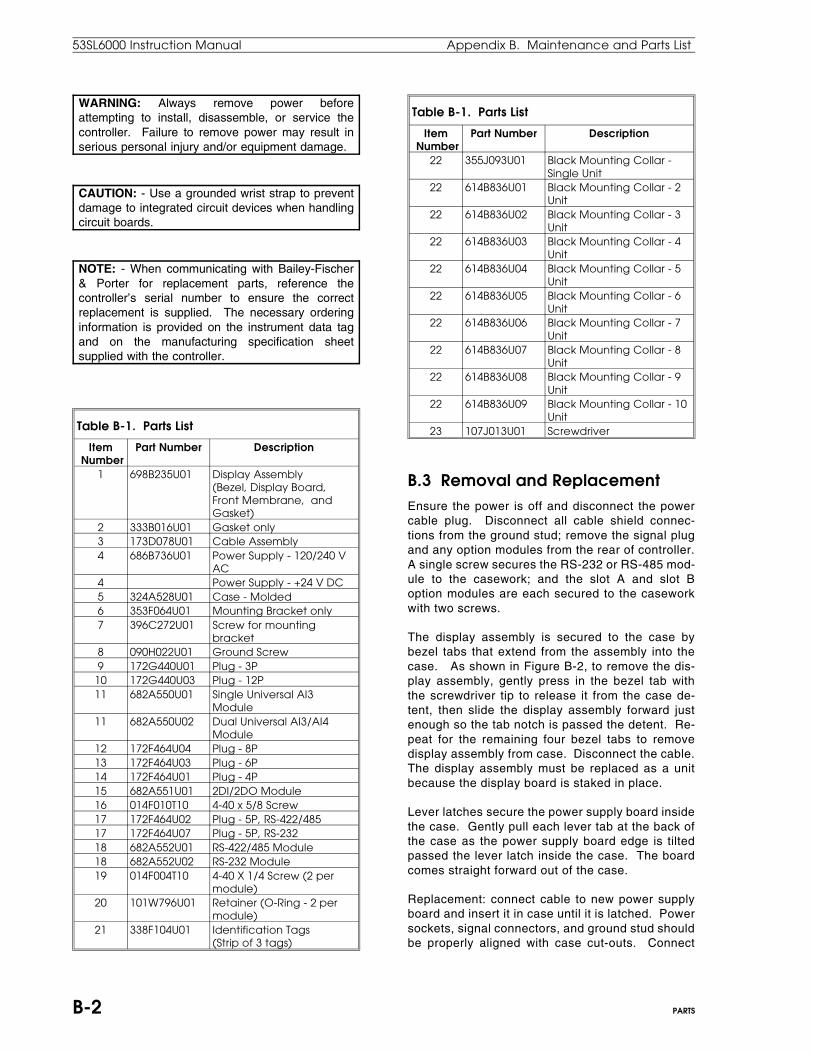
WARNING: Always remove power beforeattempting to install, disassemble, or service thecontroller. Failure to remove power may result inserious personal injury and/or equipment damage.
CAUTION: - Use a grounded wrist strap to preventdamage to integrated circuit devices when handlingcircuit boards.
NOTE: - When communicating with Bailey-Fischer& Porter for replacement parts, reference thecontroller’s serial number to ensure the correctreplacement is supplied. The necessary orderinginformation is provided on the instrument data tagand on the manufacturing specification sheetsupplied with the controller.
Table B-1. Parts List
Item Number
Part Number Description
1 698B235U01 Display Assembly (Bezel, Display Board,Front Membrane, andGasket)
2 333B016U01 Gasket only3 173D078U01 Cable Assembly4 686B736U01 Power Supply - 120/240 V
AC4 Power Supply - +24 V DC 5 324A528U01 Case - Molded6 353F064U01 Mounting Bracket only7 396C272U01 Screw for mounting
bracket8 090H022U01 Ground Screw9 172G440U01 Plug - 3P
10 172G440U03 Plug - 12P11 682A550U01 Single Universal AI3
Module11 682A550U02 Dual Universal AI3/AI4
Module12 172F464U04 Plug - 8P 13 172F464U03 Plug - 6P14 172F464U01 Plug - 4P15 682A551U01 2DI/2DO Module16 014F010T10 4-40 x 5/8 Screw17 172F464U02 Plug - 5P, RS-422/48517 172F464U07 Plug - 5P, RS-23218 682A552U01 RS-422/485 Module18 682A552U02 RS-232 Module19 014F004T10 4-40 X 1/4 Screw (2 per
module)20 101W796U01 Retainer (O-Ring - 2 per
module)21 338F104U01 Identification Tags
(Strip of 3 tags)
Table B-1. Parts List
Item Number
Part Number Description
22 355J093U01 Black Mounting Collar -Single Unit
22 614B836U01 Black Mounting Collar - 2Unit
22 614B836U02 Black Mounting Collar - 3Unit
22 614B836U03 Black Mounting Collar - 4Unit
22 614B836U04 Black Mounting Collar - 5Unit
22 614B836U05 Black Mounting Collar - 6Unit
22 614B836U06 Black Mounting Collar - 7Unit
22 614B836U07 Black Mounting Collar - 8Unit
22 614B836U08 Black Mounting Collar - 9Unit
22 614B836U09 Black Mounting Collar - 10Unit
23 107J013U01 Screwdriver
B.3 Removal and ReplacementEnsure the power is off and disconnect the powercable plug. Disconnect all cable shield connec-tions from the ground stud; remove the signal plugand any option modules from the rear of controller.A single screw secures the RS-232 or RS-485 mod-ule to the casework; and the slot A and slot Boption modules are each secured to the caseworkwith two screws.
The display assembly is secured to the case bybezel tabs that extend from the assembly into thecase. As shown in Figure B-2, to remove the dis-play assembly, gently press in the bezel tab withthe screwdriver tip to release it from the case de-tent, then slide the display assembly forward justenough so the tab notch is passed the detent. Re-peat for the remaining four bezel tabs to removedisplay assembly from case. Disconnect the cable.The display assembly must be replaced as a unitbecause the display board is staked in place.
Lever latches secure the power supply board insidethe case. Gently pull each lever tab at the back ofthe case as the power supply board edge is tiltedpassed the lever latch inside the case. The boardcomes straight forward out of the case.
Replacement: connect cable to new power supplyboard and insert it in case until it is latched. Powersockets, signal connectors, and ground stud shouldbe properly aligned with case cut-outs. Connect
53SL6000 Instruction Manual Appendix B. Maintenance and Parts List
B-2 PARTS

cable to new display assembly. To maintain envi-ronmental seal, ensure the rectangular gasket isplaced on the bezel. Slide bezel tabs into case andpush the assembly forward until tabs latch in casedetents.
Install all option modules at the rear of the control-ler; connect the signal plug and connect cableshields to the ground stud. Connect power plug.Visually check all connections before applyingpower.
Figure B-2. Bezel and Lever Tabs
B.4 Controller Confidence Test ProcedureConfidence test mode causes a suite of tests to beexecuted continuously by the controller until it istaken out of confidence test mode or until an erroroccurs.
B.4.1 Jumper Connections for the Controller Confidence TestTo prepare the controller for the confidence test,reference Figure B-3 and make the following con-nections:
1. Power Plug (TB1): ensure it is correctly wiredto the appropriate power source (see Section2, Installation).
2. Signal Plug (J12):1.0 Kohm 1% resistor between +24V and AI2.Jumper AI1 to AO1.Jumper DO1 to DI1.Jumper DO2 to DI2.
3. Communications Jack (J13):If no communication module is installed,the conF-SYS-dLE parameter should beset to oFF.
If an RS-485 Module is installed, thenjumper the following module terminal pins:Jumper between R+ and T+.Jumper between R- and T-.
If an RS-232 Module is installed, thenjumper the following module terminal pins:Jumper between TXD and RXD.Jumper between the two pins marked N.C.
4. 2DI/2DO Module Jack (J10):If this module is not installed, then jumpersare not required.
If the 2DI/2DO Module is installed, thenjumper the following module pins:Jumper between 2DI-DI3 and 2DO-NO3.Jumper between 2DI-COM and 2DO-DO3.Jumper between 2DI-DI4 and 2DO-DO4.Jumper between 2DO-NC3 and 2DO-NC4.Jumper between 2DO-NO3 and 2DO-NO4.
5. Universal Analog Input Module Jack:If this module is not installed, then jumpersare not required.
If the Universal Analog Input Module is in-stalled, then jumper the following moduleterminal pins:Plugs 1 and 2 (when either or both arepresent):392 ohm 1% resistor between IN- and I1.Jumper between IN+ and I1.24.9 Kohm 1% resistor between AI- and I2.Jumper between AI+ and I2.Jumper between IN- and RET.Jumper between AI- and RET.
Appendix B. Maintenance and Parts List 53SL6000 Instruction Manual
PARTS B-3
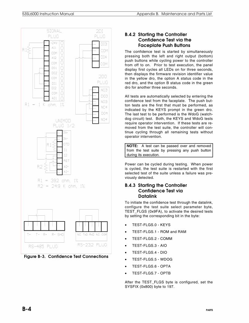
Figure B-3. Confidence Test Connections
B.4.2 Starting the Controller Confidence Test via the Faceplate Push ButtonsThe confidence test is started by simultaneouslypressing both the left and right output (bottom)push buttons while cycling power to the controllerfrom off to on. Prior to test execution, the paneldisplay first cycles all LEDs on for three seconds,then displays the firmware revision identifier valuein the yellow dro, the option A status code in thered dro, and the option B status code in the greendro for another three seconds.
All tests are automatically selected by entering theconfidence test from the faceplate. The push but-ton tests are the first that must be performed, asindicated by the KEYS prompt in the green dro.The last test to be performed is the WdoG (watch-dog circuit) test. Both, the KEYS and WdoG testsrequire operator intervention. If these tests are re-moved from the test suite, the controller will con-tinue cycling through all remaining tests withoutoperator intervention.
NOTE: A test can be passed over and removedfrom the test suite by pressing any push buttonduring its execution.
Power can be cycled during testing. When poweris cycled, the test suite is restarted with the firstselected test of the suite unless a failure was pre-viously detected.
B.4.3 Starting the Controller Confidence Test via DatalinkTo initiate the confidence test through the datalink,configure the test suite select parameter byte,TEST_FLGS (0x9FA), to activate the desired testsby setting the corresponding bit in the byte:
• TEST-FLGS.0 - KEYS
• TEST-FLGS.1 - ROM and RAM
• TEST-FLGS.2 - COMM
• TEST-FLGS.3 - AIO
• TEST-FLGS.4 - DIO
• TEST-FLGS.5 - WDOG
• TEST-FLGS.6 - OPTA
• TEST-FLGS.7 - OPTB
After the TEST_FLGS byte is configured, set theSYSFIX (0x800) byte to 197.
53SL6000 Instruction Manual Appendix B. Maintenance and Parts List
B-4 PARTS
B.4.4 Controller Confidence Test SuiteDuring confidence test execution, both vertical barsare and all annunciator LEDs except WD are lit, thered dro indicates the number of times all the se-lected tests in the suite have been executed, rollingover after 9999 passes. The green dro containsthe mnemonic of the test currently being exe-cuted.
The complete test suite contains the following teststhat execute in the order given in Table B-2:
Table B-2. Confidence Test Suite
Test DescriptionKEYS Push button test. This test requires each
push button to be pressed to becompleted successfully. The LEDsimmediately adjacent to the pushbuttons will light to indicate which pushbuttons have been pressed; otherwise,they will be off. When the KEYS test iscompleted the test is automaticallydeselected so that further action is notrequired for each successive test suitepass.
roM ROM checksum validate.rAM RAM address and data check.coMM Serial port (datalink) and option port
check. The COMM portion of the test isactivated if the conF-SYS-DLE parameteris set to on; otherwise, it will not beperformed. (For datalink, conF menu andSYS module are respectively 0x859 and0x02.)
Aio Standard analog inputs, outputs, andtransmitter power check.
dio Standard digital inputs and outputscheck.
oPtA Slot A Option I/O check.oPtb Slot B Option I/O check.WdoG Watchdog trip. When this test is selected,
the suite halts at the end of the passbecause it requires a power cycle forcompletion. Remove this test from thesuite for continuous testing by pressingany one of the push buttons during itsexecution.
B.4.5 Controller Confidence Test StatusIf a test fails, the two vertical bars start flashing, thered dro contains the pass count when the error wasdetected and the green dro indicates the test cur-rently being executed. If the test that failed is thecoMM, Aio, or dio tests, then the yellow dro willcontain the subtest number when the failure wasdetected. When a test failure occurs, no furthertesting is performed; therefore, the only way to re-
start testing is to exit, then re-enter the confidencetest. Test failure information is not lost throughpower cycles. Subtest descriptions for the coMM,Aio, and dio tests are provided in Table B-3 asfollows:
Table B-3. Factory Subtest Descriptions
Greendro
Yellowdro
Subtest
coMM 1 Serial port check.2 Serial RTS/CTS check.3 Option port check.
Aio 1 AI2 reading transmitter powersupply.
2 AI1 reading AO1 with 1 percentoutput.
3 AI1 reading AO1 with 50 percentoutput.
4 AI1 reading AO1 with 100percent output.
dio 1 DI1 reading DO1, DI2 readingDO2; both DO’s open.
2 DI1 reading DO1, DI2 readingDO2; DO1 closed, DO2 open.
3 DI1 reading DO1, DI2 readingDO2; DO1 open, DO2 closed.
4 DI1 reading DO1, DI2 readingDO2; both DOs closed.
B.4.6 Exiting the Controller Confidence Test via the Faceplate Push ButtonsTo exit the confidence test with the front panel pushbut tons, press any push but ton except themode/select pb while controller power is cycled offand then on again. When exited this way, the data-base is automatically defaulted.
B.4.7 Exiting the Controller Confidence Test via DatalinkTo exit the confidence test via the datalink withoutdefaulting the database, load the SYSFIX byte(0x800) with a value of 0.
To exit the confidence test via the datalink anddefault the database, load the SYSFIX byte(0x800) with a value of 98.
NOTE: Unless the database is defaulted after theconfidence test, the unit can not be configured viathe front panel push buttons.
Appendix B. Maintenance and Parts List 53SL6000 Instruction Manual
PARTS B-5

B.5 Defaulting the DatabaseThe database can be restored to the factory setdefault values by entering a 098 into the ProG-cS-FiX parameter using the following procedure:
NOTE: Pass-keys will not be preserved if thedatabase is defaulted.
1. Enter engineer mode by pressing and holdingthe mode pb. OPEr appears in the green dro.
2. Press the scroll forward pb until ProG appearsin the green dro.
3. Press the enter pb to accept the ProG menu.4. If cS does not appear in the yellow dro, press
the scroll forward pb until it does.5. Press the enter pb to accept the cS prompt;
SchM (scheme, the first parameter) appears inthe green dro and the control scheme promptthat was active (e.g., SnGL for single loop)appears in the red dro.
6. Press the scroll forward pb until the end of thecS prompt list is reached, which is indicated bythe FiX prompt. Each time the scroll forwardpb is pressed, a new parameter name appearsin the green dro and its default setting appearsin the red dro.
7. Press the enter pb to accept the FiX prompt;the first digit in the red dro starts blinking.
8. Use the scroll forward pb to make the first digita 0.
9. Press the shift right pb so that the second digitstarts blinking.
10. Use the scroll forward pb to make the seconddigit a 9.
11. Press the shift right pb so that the third digitstarts blinking.
12. Use the scroll forward pb to make the third digitan 8. 098 now appears in the red dro, but the8 is still blinking.
13. Press the enter pb to accept the 098. Threezeros appear in the red dro. The green dro stillcontains FiX and the yellow dro still containscS. The setpoint vertical bar indicates astopped condition with four separately lit areas(no continuous bar).
14. Press the mode pb; oFF starts blinking in thered dro. Press the scroll forward pb to changeoFF to run and press the enter pb to exit engi-neer mode.
B.6 Analog Input/Output Calibration ValuesThe calibration values can be validated and alteredusing 53HC2600 SL6 Configurator software appli-cation package running on a personal computer.Reference the software documentation and/or help
screens to display the Ai1, Ai2, and Ao1 biAS andGAin prompts. Using the SL6 configurator, enterthe values from the calibration sheet into theseprompts.
The calibration values for the universal analog in-put module can be validated and altered from thecontroller display panel. See Table 5-8 for a list ofthe calibration prompts and see Section 3 for dis-play panel procedures in engineer mode.
NOTE: The factory set calibration constants forthe analog inputs and analog outputs wererecorded on the instrument calibration sheetprovided with the controller. As stated in the noteon the Trademarks page in the front of the book,this sheet should have been retained in the eventone or more of the constants was inadvertentlychanged to the wrong value, necessitating fieldrecalibration.
B.7 Watchdog LEDThe location of the watchdog LED on the controllerfaceplate is illustrated in Figure B-4. When active,all outputs are forced to their power-off state. Thewatchdog LED will activate for any one of threeconditions:
1. Central Processing Unit (CPU) failure on thedisplay board or any other controller failurethat manifests itself as a CPU failure by caus-ing the CPU to malfunction.
2. Electrical input is not within the stated specifi-cations provided in Section 1.3.
3. Environmental specifications stated in Section1.3 are exceeded.
Figure B-4. Watchdog LED
53SL6000 Instruction Manual Appendix B. Maintenance and Parts List
B-6 PARTS

C.1 OverviewThirty-two addressable controllers (0-31) can beconnected to a datalink for information transferto/from a host, which initiates all transactions.
This section provides information to configure thesystem module (prompts iA, bAUd, dLP, dLS, anddLE), a description of the datalink protocol mes-sage field definitions, a summary table of the con-t r o l l e r m e m o r y a d d r e s s s c h e m e , a n d amnemonic-datapoint cross reference tableunit-tag•atom transfers.
C.2 Configuring the System Module for DatalinkTo initiate the controller for datalink communica-tions, respond to the system module prompts withnew values/selections if the default (Dft) settingsshown in Table C-1 requires changing.
Table C-1. System (SYS) Prompts (Datalink)
(conF Menu → SYS Module)Prompt Description Dft
iA Instrument AddrsssIt is the address assigned to thiscontroller on the datalink. Validaddresses are from 0 - 31. No twocontrollers can have the sameaddress on the datalink.
0
bAUd Baud RateThis value is set to match the datatransfer rate of the datalink. Validmenu selections are:110 4800300 9600600 19.2K1200 14.4K2400 28.8K
9600
dLE Datalink EnableSelections are as follows:on: Allows controller datalink communication.oFF: The controller is not permitted to communicate over the datalink.
on
dLP Datalink ParitySelections are as follows:on: It indicates parity generation and checking for even parity serial byte protocol is enabled.oFF: It indicates no parity protocol.
on
Table C-1. System (SYS) Prompts (Datalink)
(conF Menu → SYS Module)Prompt Description Dft
dLS Datalink StuffingSelections are as follows:on: Selects F&P byte stuffing which inserts a NULL (00) byte after every SOH (7E hex) that is not the beginning of a message. This permits user written communications software to determine the number of bytes to expect in a response message. oFF: Disables datalink stuffing.
on
tAG Tag NameAllows a 10 character datalink tagto be assigned to the controller.Four characters maximum can bedisplayed at any one time. Usingthe engineer mode shift right pushbutton, the ten character positionsare displayed as follows:0123 → 3456 → 6789Characters are selected for eachposition with the scrollforward/backward push buttons.
C.3 ProtocolThe datalink protocol requires the host to initiate alltransactions. There are two basic categories for allof the datalink message types: interrogate, whichis used to read data from an addressed controller,and change, which is used to alter a value in anaddressed controller. The addressed controller de-codes the message and provides an appropriateresponse. The protocol message field definitionsare provided in Table C- 2.
Table C-2. Datalink Protocol
Symbol DescriptionSOH Start of Header
This character, 7E, denotes the beginningof a message.
I.A. Instrument AddressThe address of the controller respondingto the transaction. It must be within arange of 00-1F (00-31 decimal).
Appendix C: Datalink Protocol
Appendix C. Datalink Protocol 53SL6000 Instruction Manual
C-1

Table C-2. Datalink Protocol
Symbol DescriptionCMD Command
It is the operation to be performed or adescription of the message that followsthe Command-I.A. byte. The Command-I.A. byte has two fields: the Commandfield (3 bits) and the I.A. field (5 bits).There are five commands as follows:Interrogate, Change, Change Bits,Acknowledge, and Response.
NUM NumberThe number of data bytes transferred orrequested. The NUM must be a range of00-32 decimal.
LO-ADD Lower Address BitsThe least significant 8 bits of a 16 bitcontroller address.
HI-ADD Higher Address BitsThe most significant 8 bits of a 16 bitcontroller address.
DATA An 8 bit data byte.XXXX Represents a variable number of data
bytes.MASK Has a 0 in every bit position that is
selected to be forced to 0.STATE Has a 1 in every bit position that is
selected to be forced to 1.LRC It is the sum of all bytes Modolo 256 of the
message not including the SOH characteror its own bit settings (LRC). It is written atthe end of the message to ensure datawas not lost in transmission.
C.3.1 Message TypesThe types of messages that are sent from the hostto the controllers on the datalink are formatted asfollows:
Host to Controller:1. Interrogate - This message requests up to 20H
consecutively stored bytes, beginning at thespecified memory address location of the ad-dressed controller.
01111110 E0H + I.A. NUM LO ADD HI ADD LRC
2. Change - This message sends up to 20H bytesof new data to the addressed controller.
01111110 A0H + I.A. NUM LO ADD HI ADDData 1 XXXXXXXXX Data N LRC
3. Change Bits - This message alters only thespecified bits in the specified bytes in the ad-dressed controller. (NUM = 2N.)
01111110 COH + I.A. NUM LO ADD HI ADDMask 1 State 1 XXXX Mask N State N LRC
4. Acknowledge - This message signals the ad-dressed controller that its last echoed changemessage was received correctly; the controllerperforms the change requested.
01111110 80H + I.A.
Controller to Host:1. Response - This message furnishes the data
requested by the Interrogate command of thehost. It is also used to echoe back the pre-vious Change message of the host.
01111110 20H + I.A. NUM LO ADD HI ADD Data1 XXXXX Data N LRC
C.3.2 Transaction ExamplesExample A - The host requests 9 bytes of databeginning at hexadecimal memory address 1000Hfrom the controller at datalink address 03.
1. Host sends Interrogate message.
01111110 11100011 00001001 00000000 SOH Cmd + I.A. NUM LO ADD
00010000 11111100 HI ADD LRC
2. Controller sends response message.
01111110 00100011 00001001 00000000 SOH Cmd + I.A. NUM LO ADD
00010000 XXXXX XXXXX XXXXX YYYYYYYY HI ADD Data 1 . . . . . . . Data 9 LRC
Example B - The host sends 2 bytes of new data,to be loaded into the controller at datalink address03 beginning at hexadecimal memory address1000H.
1. Host sends Change message.
01111110 10100011 00000010 00000000 SOH Cmd + I.A. NUM LO ADD00010000 00001000 00001100 11001001 HI ADD Data 1 Data 2 LRC
53SL6000 Instruction Manual Appendix C. Datalink Protocol
C-2

2. Controller sends Response message.
01111110 00100011 00000010 00000000 SOH Cmd + I.A. NUM LO ADD
00010000 00001000 00001100 01001001 HI ADD Data 1 Data 2 LRC
3. Host sends Acknowledge message.
01111110 10000011 SOH Cmd + I.A.
4. The controller performs the change requestedat the end of the current scan.
C.4 Mnemonic-to-Datapoint Cross ReferenceMany of the mnemonic prompts are actually alpha-numeric representations of datapoint parametersthat are used to configure controller operation.There are six datapoint types which are briefly de-scribed in Table C-3. In the data format descriptionof the table, subscripts H and D are used to denotehexadecimal and decimal numbers respectively.
Table C-3. Datapoint Types
Data-Point
Size Data Format Description
B 1 byte
It is a positive integer from 0 to 255.
L 1 bit A single binary bit with a logicalvalue of 0 or 1.
C 3bytes
A floating point value that has aresolution of one part in 32,768 anda dynamic range of ± 1038. The firsttwo bytes represent a 2’scomplement notation in fractionalform (2-n ) whose absolute value isbetween 0.5 and 0.9999. The thirdbyte is the power of 2 in 2’scomplement notation. (See FigureC-1 for examples.)
H 5bytes
A floating point value that has aresolution of one part in 2 billionand a dynamic range of ± 1038.The first four bytes represent a 2’scomplement notation in fractionalform (2-n) whose absolute value isbetween 0.5 and 0.9999. The fifthbyte is the power of 2 in 2’scomplement notation.(See Figure C-1 for examples.)
A 10bytes
A text string that is 10 charactersmaximum.
Table C-3. Datapoint Types
Data-Point
Size Data Format Description
F 5bytes
A text string that is 5 charactersmaximum. Type F datapoints are asubset of the type A datapointsand therefore have the samememory assignment area.
C.4.1 Database Starting AddressesTable C-4 provides the starting address and thenumber of datapoints for each data type in the53SL6000 controller.
Table C-4. Database Starting Addresses
Type StartAddress
Number ofElements
Size ofElement
B 0800H 75 1L 084BH 128 1/8C 085BH 124 3H 09CFH 5 5
A-F 09E8H 2-4 10-5
C.4.2 Controller Memory Address SchemeThe location of the datapoint in the controller mem-ory can be calculated from the base address forthat datapoint type. The datapoint types, with theirbase addresses and memory location algorithms,are provided in Table C-5 (subscripts H and D areused to denote hexadecimal and decimal numbersrespectively).
Table C-5. Datapoint Addresses
Type BaseAddr
AddressCalculation
B 0800H Address = B Base + (B Number) = 800H + (B Number)Address example: B012 location= 0800H + 12D = 800H + CH = 80CH
L 084BH Address = L Base + (L Number/8) = 84BH + (L Number/8)Remainder = bit position in byteAddress example: L014 location= 84BH + 14/8 = 84CH, bit 6(remainder).
C 085BH Address = C Base + (3 X C Number) = 85BH + (3 X C Number)Address example: C011 location85BH + (3 X 11) = 85BH + 33D
= 85BH + 21H = 87CH.
Appendix C. Datalink Protocol 53SL6000 Instruction Manual
C-3
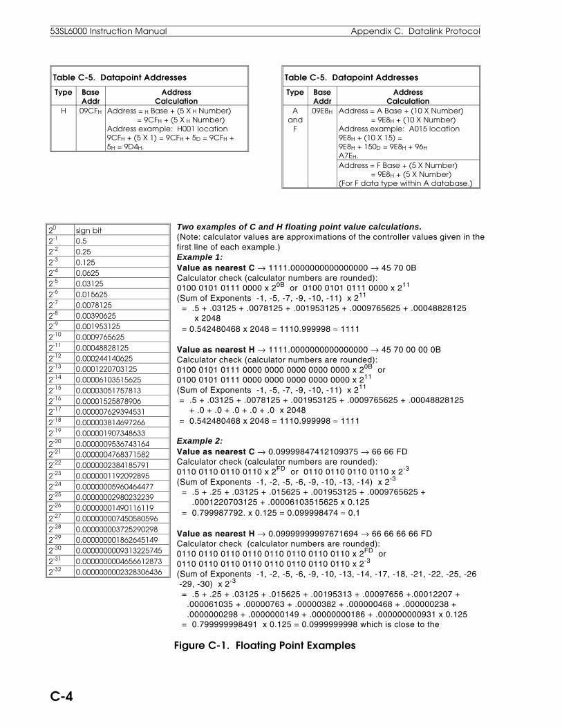
Table C-5. Datapoint Addresses
Type BaseAddr
AddressCalculation
H 09CFH Address = H Base + (5 X H Number) = 9CFH + (5 X H Number)Address example: H001 location9CFH + (5 X 1) = 9CFH + 5D = 9CFH +5H = 9D4H.
Table C-5. Datapoint Addresses
Type BaseAddr
AddressCalculation
Aand
F
09E8H Address = A Base + (10 X Number) = 9E8H + (10 X Number)Address example: A015 location9E8H + (10 X 15) =9E8H + 150D = 9E8H + 96H A7EH.Address = F Base + (5 X Number) = 9E8H + (5 X Number)(For F data type within A database.)
20 sign bit 2-1 0.52-2 0.252-3 0.1252-4 0.06252-5 0.031252-6 0.0156252-7 0.00781252-8 0.003906252-9 0.0019531252-10 0.00097656252-11 0.000488281252-12 0.0002441406252-13 0.00012207031252-14 0.000061035156252-15 0.000030517578132-16 0.000015258789062-17 0.0000076293945312-18 0.0000038146972662-19 0.0000019073486332-20 0.00000095367431642-21 0.00000047683715822-22 0.00000023841857912-23 0.00000011920928952-24 0.000000059604644772-25 0.000000029802322392-26 0.000000014901161192-27 0.0000000074505805962-28 0.0000000037252902982-29 0.0000000018626451492-30 0.00000000093132257452-31 0.00000000046566128732-32 0.0000000002328306436
Two examples of C and H floating point value calculations.(Note: calculator values are approximations of the controller values given in thefirst line of each example.)Example 1:Value as nearest C → 1111.0000000000000000 → 45 70 0BCalculator check (calculator numbers are rounded):0100 0101 0111 0000 x 20B or 0100 0101 0111 0000 x 211
(Sum of Exponents -1, -5, -7, -9, -10, -11) x 211
= .5 + .03125 + .0078125 + .001953125 + .0009765625 + .00048828125 x 2048 = 0.542480468 x 2048 = 1110.999998 ≈ 1111
Value as nearest H → 1111.0000000000000000 → 45 70 00 00 0BCalculator check (calculator numbers are rounded):0100 0101 0111 0000 0000 0000 0000 0000 x 20B or0100 0101 0111 0000 0000 0000 0000 0000 x 211
(Sum of Exponents -1, -5, -7, -9, -10, -11) x 211
= .5 + .03125 + .0078125 + .001953125 + .0009765625 + .00048828125 + .0 + .0 + .0 + .0 + .0 x 2048 = 0.542480468 x 2048 = 1110.999998 ≈ 1111
Example 2:Value as nearest C → 0.09999847412109375 → 66 66 FDCalculator check (calculator numbers are rounded):0110 0110 0110 0110 x 2FD or 0110 0110 0110 0110 x 2-3
(Sum of Exponents -1, -2, -5, -6, -9, -10, -13, -14) x 2-3
= .5 + .25 + .03125 + .015625 + .001953125 + .0009765625 + .0001220703125 + .00006103515625 x 0.125 = 0.799987792. x 0.125 = 0.099998474 ≈ 0.1
Value as nearest H → 0.09999999997671694 → 66 66 66 66 FDCalculator check (calculator numbers are rounded):0110 0110 0110 0110 0110 0110 0110 0110 x 2FD or 0110 0110 0110 0110 0110 0110 0110 0110 x 2-3
(Sum of Exponents -1, -2, -5, -6, -9, -10, -13, -14, -17, -18, -21, -22, -25, -26 -29, -30) x 2-3
= .5 + .25 + .03125 + .015625 + .00195313 + .00097656 +.00012207 + .000061035 + .00000763 + .00000382 + .000000468 + .000000238 + .0000000298 + .0000000149 + .00000000186 + .000000000931 x 0.125 = 0.799999998491 x 0.125 = 0.0999999998 which is close to the
Figure C-1. Floating Point Examples
53SL6000 Instruction Manual Appendix C. Datalink Protocol
C-4

C.4.3 Database Prompt-to-Datapoint Cross ReferenceTable C-6 is provided as a parameter prompt-to-datapoint cross reference.
Table C-6. Prompt-to-Datapoint Cross Reference
DBase Module DBaseParameter
NetworkReference
Ai1 Ai C114bASE L088cALS C066cALZ B018dFLt B004SPAn C062SQrt L089ZEro C064
Ai2 Ai C115bASE L096cALS C067cALZ B019dFLt B005SPAn C063SQrt L097ZEro C065
Ai3 Ai C116Ai4 Ai C117Ai5 Ai C118Ai6 Ai C119Ai7 Ai C120Ai8 Ai C121Ao1 Ao C069
bASE L104cALS C068cALZ B020
Ao2 Ao C070Ao3 Ao C071chr K01 C088
K02 C089K03 C090K04 C091K05 C092K06 C093K07 C094K08 C095K09 C096K10 C097K11 C098K12 C099K13 C100K14 C101K15 C102K16 C103
Table C-6. Prompt-to-Datapoint Cross Reference
DBase Module DBaseParameter
NetworkReference
chr(cont)
K17 C104K18 C105K19 C106K20 C107K21 C108K22 C109K23 C110K24 C111K25 C112K26 C113
[LStP] B022 StEP B021
[tiMER] C122
Appendix C. Datalink Protocol 53SL6000 Instruction Manual
C-5
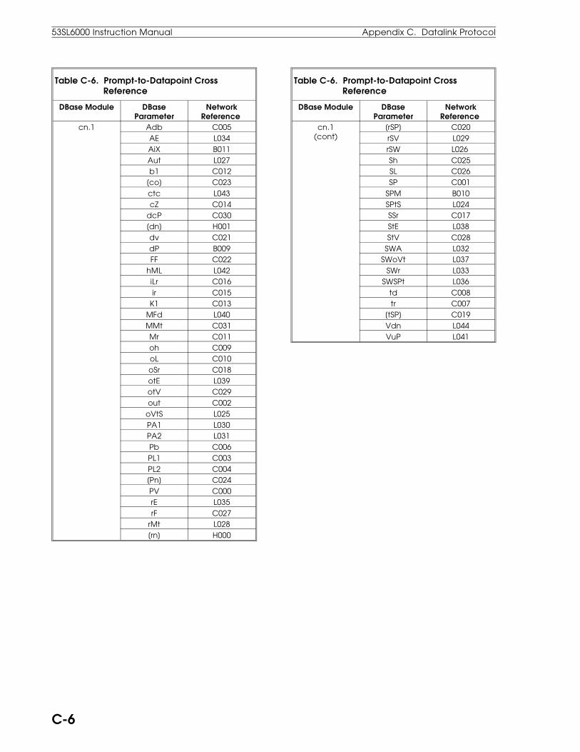
Table C-6. Prompt-to-Datapoint Cross Reference
DBase Module DBaseParameter
NetworkReference
cn.1 Adb C005AE L034AiX B011Aut L027b1 C012
[co] C023ctc L043cZ C014
dcP C030[dn] H001dv C021dP B009FF C022
hML L042iLr C016ir C015
K1 C013MFd L040MMt C031Mr C011oh C009oL C010oSr C018otE L039otV C029out C002
oVtS L025PA1 L030PA2 L031Pb C006PL1 C003PL2 C004[Pn] C024PV C000rE L035rF C027
rMt L028[rn] H000
Table C-6. Prompt-to-Datapoint Cross Reference
DBase Module DBaseParameter
NetworkReference
cn.1(cont)
[rSP] C020rSV L029rSW L026 Sh C025SL C026SP C001
SPM B010SPtS L024SSr C017StE L038StV C028
SWA L032SWoVt L037
SWr L033SWSPt L036
td C008tr C007
[tSP] C019Vdn L044VuP L041
53SL6000 Instruction Manual Appendix C. Datalink Protocol
C-6
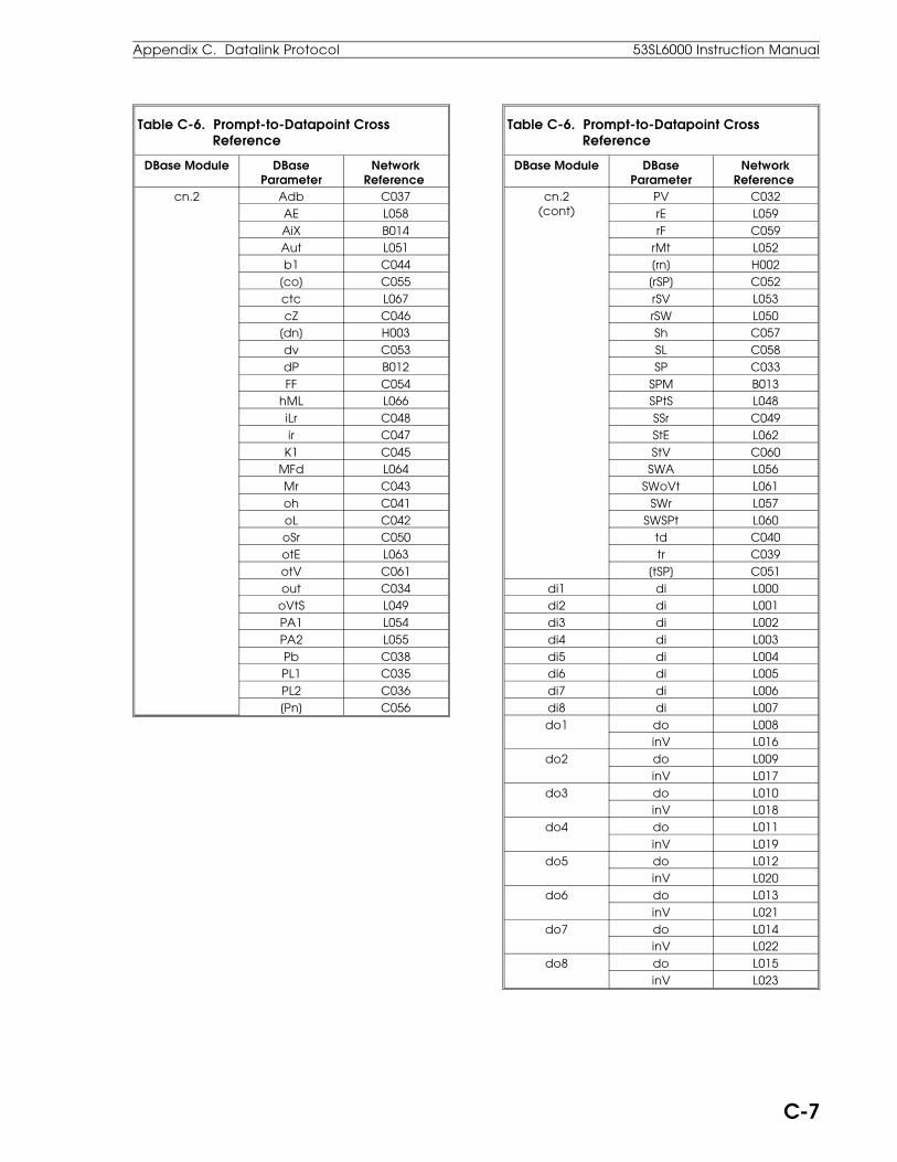
Table C-6. Prompt-to-Datapoint Cross Reference
DBase Module DBaseParameter
NetworkReference
cn.2 Adb C037AE L058AiX B014Aut L051b1 C044
[co] C055ctc L067cZ C046
[dn] H003dv C053dP B012FF C054
hML L066iLr C048ir C047
K1 C045MFd L064Mr C043oh C041oL C042oSr C050otE L063otV C061out C034
oVtS L049PA1 L054PA2 L055Pb C038PL1 C035PL2 C036[Pn] C056
Table C-6. Prompt-to-Datapoint Cross Reference
DBase Module DBaseParameter
NetworkReference
cn.2(cont)
PV C032rE L059rF C059
rMt L052[rn] H002[rSP] C052rSV L053rSW L050Sh C057SL C058SP C033
SPM B013SPtS L048SSr C049StE L062StV C060
SWA L056SWoVt L061
SWr L057SWSPt L060
td C040tr C039
[tSP] C051di1 di L000di2 di L001di3 di L002di4 di L003di5 di L004di6 di L005di7 di L006di8 di L007do1 do L008
inV L016do2 do L009
inV L017do3 do L010
inV L018do4 do L011
inV L019do5 do L012
inV L020do6 do L013
inV L021do7 do L014
inV L022do8 do L015
inV L023
Appendix C. Datalink Protocol 53SL6000 Instruction Manual
C-7

Table C-6. Prompt-to-Datapoint Cross Reference
DBase Module DBaseParameter
NetworkReference
EZ [Abrt] L074APLd L073cM B016
dout C075dPV C074
dPPV C072EPb C079Etd C081Etr C080KP C077LPS B015
nrun L076PLiM L072run L075StS B017
tLiM C073tP C076
WP C078Fnc K01 C082
K02 C083K03 C084K04 C085K05 C086K06 C087
oPr Ai.E L123ALM.E L124di7.E L120di8.E L121EZ.E L127
hLc.E L126Pid.E L125StP.E L122
PrG Ao1.i B043Ao2.i B044Ao3.i B045chr.M B038chr.A B039chr.b B053chr.c B054do1.i B067do2.i B068do3.i B069do4.i B070do5.i B071do6.i B072do7.i B073do8.i B074doFb B041EXrF B042FiX B000
Table C-6. Prompt-to-Datapoint Cross Reference
DBase Module DBaseParameter
NetworkReference
Fnc.M B033PrG
(cont)Fnc.A B034Fnc.b B035Fnc.c B036Fnc.d B037Fnc.E B046Fnc.F B047
LG1.M B055LG1.A B056LG1.b B057LG2.M B058LG2.A B059LG2.b B060LG3.M B061LG3.A B062LG3.b B063LG4.M B064LG4.A B065LG4.b B066
PVt B040PVt.2 B052SchM B026cS.A B027cS.b B028cS.c B029cS.d B030cS.E B031cS.F B032cS.h B048cS.J B049cS.K B050cS.L B051
SYS bAUd B002cKEY F003dLE L113dLP L112dLS L114iA B001
oPtA B006oPtb B007PKEY F002tAG A000
C.5 Executing Controller Self Tests via DatalinkThe procedure to execute the controller self testsvia the datalink can be found in Appendix B, Main-tenance and Parts List.
53SL6000 Instruction Manual Appendix C. Datalink Protocol
C-8

[0]: Logic level zero. 0.0: The value zero. 0.05: Digital filter in seconds. 0.1: Digital filter in seconds. 0.3: Digital filter in seconds. 0.6: Digital filter in seconds. 0.7: Digital filter in seconds. 0 to 13: Characterizer step mode list. 0-20: 0-20 mA input. 0 to 31: Instrument addresses 0 to 31. 0-80: 0-80 millivolt universal Ai option. 0-5V: 0-5 volts analog input. [1]: Logic level one. 1.0: The value one. 1.5: Digital filter in seconds. 1.8: Digital filter in seconds. 1-5V: 1-5 volts analog input. 3.1: Digital filter in seconds. 3SEG: Segment third order polynomial. 3TrM: 3 wire RTD. 4.2: Digital filter in seconds. 4-20: 4-20 mA input. 4TrM: 4 wire RTD. 6.3: Digital filter in seconds. 9.0: Digital filter in seconds. 10c: 10 ohm copper RTD. 12.7: Digital filter in seconds. 18.6: Digital filter in seconds. 25.5: Digital filter in seconds. 37.2: Digital filter in seconds. 51.1: Digital filter in seconds. 53c: 53 ohm copper RTD. 75.0: Digital filter in seconds. 100c: 100 ohm copper RTD. 102: Digital filter in seconds. 110: 110 baud. 100n: 100 ohm nickel RTD. 120n: 120 ohm nickel RTD. 150: Digital filter in seconds. 205: Digital filter in seconds. 300: 300 baud. 300: Digital filter in seconds. 410: Digital filter in seconds. 600: 600 baud. 600: Digital filter in seconds. 819: Digital filter in seconds. 1200: 1200 baud. 1200: Digital filter in seconds. 1638: Digital filter in seconds. 2400: 2400 baud. 4800: 4800 baud. 9600: 9600 baud. 14.4K: 14,400 baud. 19.2K: 19,200 baud. 28.8K: 28,800 baud.
Adb: Alarm deadband. Ai: Analog input module. Ai1: Analog input 1 value. Ai2: Analog input 2 value. Ai3: Analog input 3 value. Ai4: Analog input 4 value. Ai5: Analog input 5 value. Ai6: Analog input 6 value. Ai7: Analog input 7 value. Ai8: Analog input 8 value. Ai.1: Analog input 1 module. Ai.2: Analog input 2 module. Ai.3: Analog input 3 module. Ai.4: Analog input 4 module. Ai.E: Enable oPEr Ai7 and Ai8 access. AiX: Alarm index. ALG: Algebraic function. ALM.E: Enable oPEr alarm access. And: A AND B logic function. /And: NOT (A AND B) logic function. And/: A AND (NOT B) logic function. APLd: Easy-Tune auto parameter load. Ao: Analog output module. Ao1: Analog output value 1. Ao2: Analog output value 2. Ao3: Analog output value 3. Ao1.i: Analog output 1 input selector. Ao2.i: Analog output 2 input selector. Ao3.i: Analog output 3 input selector. Ao.1: Analog output 1 module. Aut: cn.1 auto status. Aut.2: cn.2 auto status. b1: Remote setpoint bias. bASE: Current base (0/4-20 mA). bAud: Datalink transfer rate. b.cJc: CJC calibration constant. biAS: Zero offset calibration constant. bMV: Zero offset mv calibration constant. b.tc: Thermocouple type B. cASc: Cascade control scheme. chr: Characterizer module. chr.A: Characterizer A input selector. chr.b: Characterizer b input selector. chr.c: Characterizer c input selector. chr.M: Characterizer mode selector. cKEY: Configuration pass-key module cM: Easy-Tune control mode. cn.1: Control module 1. cn.2: Control module 2. conF: Configure menu. cS: Control scheme module. cSA: Control scheme analog A input. cSb: Control scheme analog B input cSc: Control scheme analog C input. cSd: Control scheme analog D input.
Appendix D: Prompt List
Appendix D. Prompt List 53SL6000 Instruction Manual
D-1
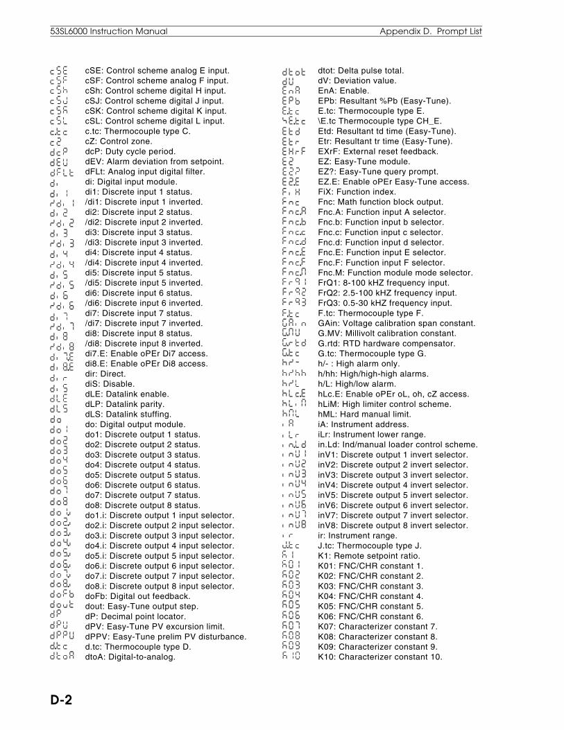
cSE: Control scheme analog E input. cSF: Control scheme analog F input. cSh: Control scheme digital H input. cSJ: Control scheme digital J input. cSK: Control scheme digital K input. cSL: Control scheme digital L input. c.tc: Thermocouple type C. cZ: Control zone. dcP: Duty cycle period. dEV: Alarm deviation from setpoint. dFLt: Analog input digital filter. di: Digital input module. di1: Discrete input 1 status. /di1: Discrete input 1 inverted. di2: Discrete input 2 status. /di2: Discrete input 2 inverted. di3: Discrete input 3 status. /di3: Discrete input 3 inverted. di4: Discrete input 4 status. /di4: Discrete input 4 inverted. di5: Discrete input 5 status. /di5: Discrete input 5 inverted. di6: Discrete input 6 status. /di6: Discrete input 6 inverted. di7: Discrete input 7 status. /di7: Discrete input 7 inverted. di8: Discrete input 8 status. /di8: Discrete input 8 inverted. di7.E: Enable oPEr Di7 access. di8.E: Enable oPEr Di8 access. dir: Direct. diS: Disable. dLE: Datalink enable. dLP: Datalink parity. dLS: Datalink stuffing. do: Digital output module. do1: Discrete output 1 status. do2: Discrete output 2 status. do3: Discrete output 3 status. do4: Discrete output 4 status. do5: Discrete output 5 status. do6: Discrete output 6 status. do7: Discrete output 7 status. do8: Discrete output 8 status. do1.i: Discrete output 1 input selector. do2.i: Discrete output 2 input selector. do3.i: Discrete output 3 input selector. do4.i: Discrete output 4 input selector. do5.i: Discrete output 5 input selector. do6.i: Discrete output 6 input selector. do7.i: Discrete output 7 input selector. do8.i: Discrete output 8 input selector. doFb: Digital out feedback. dout: Easy-Tune output step. dP: Decimal point locator. dPV: Easy-Tune PV excursion limit. dPPV: Easy-Tune prelim PV disturbance. d.tc: Thermocouple type D. dtoA: Digital-to-analog.
dtot: Delta pulse total. dV: Deviation value. EnA: Enable. EPb: Resultant %Pb (Easy-Tune). E.tc: Thermocouple type E. \E.tc Thermocouple type CH_E. Etd: Resultant td time (Easy-Tune). Etr: Resultant tr time (Easy-Tune). EXrF: External reset feedback. EZ: Easy-Tune module. EZ?: Easy-Tune query prompt. EZ.E: Enable oPEr Easy-Tune access. FiX: Function index. Fnc: Math function block output. Fnc.A: Function input A selector. Fnc.b: Function input b selector. Fnc.c: Function input c selector. Fnc.d: Function input d selector. Fnc.E: Function input E selector. Fnc.F: Function input F selector. Fnc.M: Function module mode selector. FrQ1: 8-100 kHZ frequency input. FrQ2: 2.5-100 kHZ frequency input. FrQ3: 0.5-30 kHZ frequency input. F.tc: Thermocouple type F. GAin: Voltage calibration span constant. G.MV: Millivolt calibration constant. G.rtd: RTD hardware compensator. G.tc: Thermocouple type G. h/- : High alarm only. h/hh: High/high-high alarms. h/L: High/low alarm. hLc.E: Enable oPEr oL, oh, cZ access. hLiM: High limiter control scheme. hML: Hard manual limit. iA: Instrument address. iLr: Instrument lower range. in.Ld: Ind/manual loader control scheme. inV1: Discrete output 1 invert selector. inV2: Discrete output 2 invert selector. inV3: Discrete output 3 invert selector. inV4: Discrete output 4 invert selector. inV5: Discrete output 5 invert selector. inV6: Discrete output 6 invert selector. inV7: Discrete output 7 invert selector. inV8: Discrete output 8 invert selector. ir: Instrument range. J.tc: Thermocouple type J. K1: Remote setpoint ratio. K01: FNC/CHR constant 1. K02: FNC/CHR constant 2. K03: FNC/CHR constant 3. K04: FNC/CHR constant 4. K05: FNC/CHR constant 5. K06: FNC/CHR constant 6. K07: Characterizer constant 7. K08: Characterizer constant 8. K09: Characterizer constant 9. K10: Characterizer constant 10.
53SL6000 Instruction Manual Appendix D. Prompt List
D-2

K11: Characterizer constant 11. K12: Characterizer constant 12. K13: Characterizer constant 13. K14: Characterizer constant 14. K15: Characterizer constant 15. K16: Characterizer constant 16. K17: Characterizer constant 17. K18: Characterizer constant 18. K19: Characterizer constant 19. K20: Characterizer constant 20. K21: Characterizer constant 21. K22: Characterizer constant 22. K23: Characterizer constant 23. K24: Characterizer constant 24. K25: Characterizer constant 25. K26: Characterizer constant 26. KEY: Key module. KP: Easy-Tune calculated gain. K-SP: Ratio setpoint mode. K.tc: Thermocouple type K. -/L: Low alarm only. LFLo: Linear flow compensation. LG: Logic module. LG1: Logic module 1 output. LG1.A: Logic module 1 A input selector. LG1.b: Logic module 1 b input selector. LG1.M: Logic module 1 mode selector. LG2: Logic module 2 output. LG2.A: Logic module 2 A input selector. LG2.b: Logic module 2 b input selector. LG2.M: Logic module 2 mode selector. LG3: Logic module 3 output. LG3.A: Logic module 3 A input selector. LG3.b: Logic module 3 b input selector. LG3.M: Logic module 3 mode selector. LG4: Logic module 4 output. LG4.A: Logic module 4 A input selector. LG4.b: Logic module 4 b input selector. LG4.M: Logic module 4 mode selector. L/LL: Low/low-low alarm indicators. LiM: Limiter function. L.LiM: Low limiter control scheme. Lin: Linear. LoG: Logarithmic function. LSEG: Linear segment characterize. L.tc: Thermocouple type L. MFd: Manual feedback disable. MMt: Minimum manual time. Mr: Manual reset. nc: No connect. no: No. nonE: None. n.tc: Thermocouple type n. oFF: Off. oh: Output high limit. oL: Output low limit. oPEr: Operator menu. oPr: Operator module. oPtA: Option A.
oPtb: Option b. or: A OR B logic function. or/: A OR NOT B logic function. /or: NOT (A OR B) logic function. oSr: Output slew rate. out: Control output. oVtS: Output track status. P: Proportional. PD: Proportional and derivative. PI: Proportional and integral. PID: Proportional, integral, derivative. PA1: cn.1 AL1 status. PA2: cn.1 AL2 status. PA1.2: cn.2 PL1 status. PA2.2: cn.2 PL2 status. Pb: Proportional band. PGrM: Setpoint Programmer. Pid.E: Enable oPEr tuning access. PKEY: Program menu pass-key module. PL1: Process alarm limit 1. PL2: Process alarm limit 2. PLiM: Enable parameter modify. PL.tc: Thermocouple type PLII (platinel). PoLY: Polynomial function. PoWr: Exponential function. P.DDD: Red/green dro decimal selection. PP.DD: Red/green dro decimal selection. PPP.D: Red/green dro decimal selection. PPPP: Red/green dro no decimal. PrG: Program module. ProG: Program menu. Pt.85: 100 ohm platinum RTD .00385α. Pt.91: 100 ohm platinum RTD .00391α. Pt.92: 100 ohm platinum RTD .00392α. PV: Process variable. PVt: Process variable tracking loop 1. PVt.2: Process variable tracking loop 2. rEV: Reverse. rMt: Remote. rSV: Reverse output indication. rSW: Reverse control action. r.tc: Thermocouple type r. rtd: RTD 3 or 4 wire selection. run: Run. run?: Run query. SchM: Control scheme selector. SEL: Selector function. SFLo: Square root flow compensator. Sh: Setpoint high limit. SL: Setpoint low limit. SnGL: Single loop control scheme. SP: Control setpoint. SPAn: Span. SPM: Setpoint mode. SPtS: Setpoint track status. SQrt: Square root signal. SSr: Setpoint slew rate. S.tc: Thermocouple type S.
Appendix D. Prompt List 53SL6000 Instruction Manual
D-3

\S.tc: Thermocouple type CH_S. Std: Standard setpoint mode. StEP: Programmer step. StoP: Stop. StP.E: Enable oPEr prog step access. StV: Setpoint track value. SWA: Auto push button. SWr: Remote push button. SuMM: Summation function. SYS: System module. tAG: Unit tagname. td: Derivative time. tLiM: Easy-Tune settling time limiting. tP: Easy-Tune first order time constant. tr: Reset time. t.tc: Thermocouple type t. u.tc: Thermocouple type u. Vdn: Control valve down signal. Vup: Control valve up signal. Wp: Easy-Tune calculated dead-time. Xor: A XOR B logic function. /Xor: NOT (A XOR B) logic function. YES: Yes. Zero: Zero.
53SL6000 Instruction Manual Appendix D. Prompt List
D-4

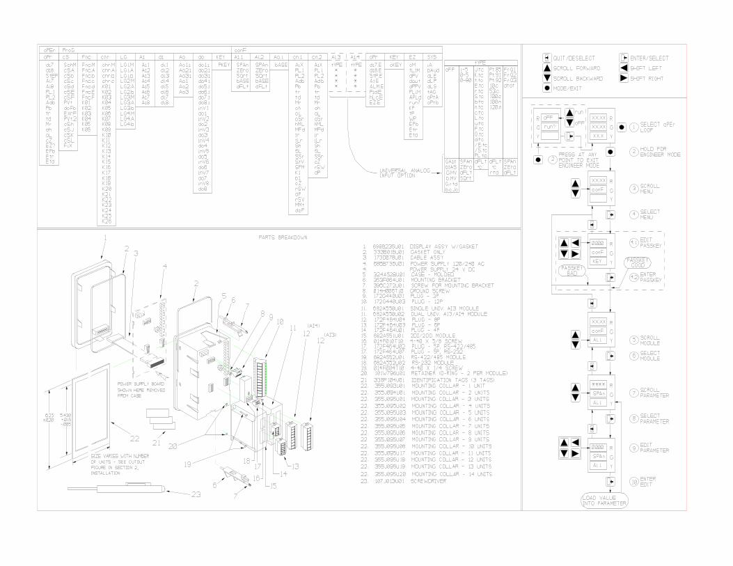

The Company’s policy is one of continuous product improvement and theright is reserved to modify the information contained herein without notice.© 2001 ABB Automation Inc. Printed in USA
ABB Inc.125 East County Line RoadWarminster, PA 18974 USATel. 215-674-6000FAX: 215-674-7183
ABB Instrumentation LtdHoward Road, St. NeotsCambs. England, PE19 3EUTel. +44 (0) 1480-475-321FAX: +44 (0) 1480-217-948
ABB Instrumentation S.p.AVia Sempione 24320016 Pero (Milano) ItalyTel: +39 (02) 33928 1Fax: +39 (02) 33928 240
ABB Automation Products GmbHIndustriestr. 28D-65760 Eschborn GermanyTel: +49 (0) 6196 800 0Fax: +49 (0) 6196 800 1849
PN
2499
1