MANUAL DE INSTRUÇÕES DO MULTÍMETRO DIGITAL DE BANCADA MODELO MD-6700 · MANUAL DE INSTRUÇÕES...
104
MANUAL DE INSTRUÇÕES DO MULTÍMETRO DIGITAL DE BANCADA MODELO MD-6700 (versão em Inglês) Leia atentamente as instruções contidas neste manual antes de iniciar o uso do instrumento
-
Upload
nguyentuyen -
Category
Documents
-
view
243 -
download
0
Transcript of MANUAL DE INSTRUÇÕES DO MULTÍMETRO DIGITAL DE BANCADA MODELO MD-6700 · MANUAL DE INSTRUÇÕES...
MANUAL DE INSTRUÇÕES DO MULTÍMETRO DIGITAL DE
BANCADA MODELO MD-6700 (versão em Inglês)
Leia atentamente as instruções contidas neste manual antes de
iniciar o uso do instrumento
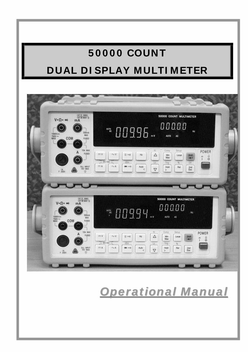
50000 COUNT
DUAL DISPLAY MULTIMETER
OOppeerraattiioonnaall MMaannuuaall
1
Table of Contents Section 1. Introduction
1-1 Introducing the 50,000 Count Dual Display Multimeter 1 1-2 Features 2 1-3 Options and Accessories 3 1-4 How to use this manual 4 1-5 Safety 5
Section 2. Getting Started 2-1 Introduction 7 2-2 Getting Started 7 2-3 Turning the Meter ON 11 2-4 Selecting Current Input Terminals and 11
Measurement Range 2-5 Using the Pushbuttons 11 2-6 Basic Measurement Examples 12 2-7 Rack Mounting 18
Section 3. Front Panel Operation 3-1 Introduction 19 3-2 Front Panel Operations 19 3-3 Primary and Secondary Displays 20 3-4 Input Terminals 22 3-5 Initialization of Measurement Conditions 23 3-6 Selecting A Measurement Function 23 3-7 Selecting Measurement Range 26 3-8 Selecting Secondary Display 27 3-9 Entering Setup Mode 29 3-10 Selecting Local Operation Mode 31 3-11 Operating Arithmetic Functions 31 3-12 Selecting Trigger Mode 38
Section 4. Measurement Applications Examples 4-1 Introduction 41 4-2 Applications for Using Dual Display 41
4-2-1 Dual Display Operation Examples 42 4-3 Measuring Resistance 45 4-4 Measuring True RMS AC+DC 46
2
Section 5. Calibrating the Meter 5-1 Introduction 47 5-2 Environment Condition 47 5-3 Warm up 47 5-4 Recommended Test Equipment 48
Section 6. RS-232 Remote Operation 6-1 Introduction 49 6-2 RS-232 Interface Overview 49 6-3 RS-232 Interface Parameter Set up 49 6-4 Using Commands 51
6-4-1 Types of Commands 51 6-4-2 Command Syntax 52
6-5 Instructions of Command Sets 53 6-5-1 Key Commands 53 6-5-2 Set Commands 54 6-5-3 Query Commands 59
6-6 Remote Program Examples Using RS-232 interface 65
Section 7. GPIB Remote Operation 7-1 Introduction 71 7-2 Description of the GPIB 71 7-3 GPIB Interface Parameters Setup 71 7-4 Commands Summary 72
7-4-1 Overview of Command Type and Formats 72 7-4-2 Response Message Data Types 73 7-4-3 Status Reporting 73
7-5 Instructions of Command Sets 77 7-5-1 IEEE 488.2 Common Commands 77 7-5-2 SCPI Commands 79 7-5-3 SCPI Commands Summary 87
7-6 Remote Program Examples Using GPIB interface 89
Appendices
A. Specifications 93 B. Maintenance 101
3
Section 1
Introduction
1-1 Introducing the 50,000 Count Dual Display Multimeter
NOTE
1. This operation manual contains information and warning that must be followed to ensure user operation safety and to retain the meter safety condition.
Precaution!
TO ENSURE PERSONAL SAFETY AND TO AVOID DAMAGING THE METER AND THE EQUIPMENT CONNECTED, READ “GETTING
STARTED” IN SECTION 2-2 BEFORE USING THE METER.
The meter is 50,000 count Dual Display Multi-meter. The meter is designed for bench-top, field service, and system applications with a high performance/price
ratio.
With the RS-232 computer interface (standard), the meter is fully programmable for use on the RS-232 interface.
With the IEEE-488 computer interface (optional) installed, the meter is fully programmable for use on IEEE-488.1 interface bus (1978). The meter is also
designed in compliance with supplemental standard IEEE-488.2 (1987).
4
1-2 Features The main features provided by the meter are:
50,000 Count Dual Display
Vacuum-fluorescent Display (VFD)
Low Cost and High Performances
DCV, ACV, DCA, ACA, Frequency, Diode Continuity
DCV Measurement to 1000V, ACV to 750V (Up 1200Vdc, 1000Vac are measurable)
AC/DC Current Measurements to 10A (Up to 20A is measurable in less than 20 seconds).
True RMS (AC, AC+DC), 30Hz to 100kHz Measurement Bandwidth.
AC Current Measurement Bandwidth from 30Hz to 20kHz.
Frequency Measurements Up to 500KHz, 0.01 Hz Resolution.
Resistance Measurement Up to 50 M Ω, 10m Ω Resolutions.
dBm measurement with variable reference impedance from 2 Ω to 8000Ω.
Auto or Lock Ranging Relative Calculation.
Auto or Lock Ranging Dynamic Recording (MIN/MAX) with elapsed time.
Compare (Hi/Lo/Pass) function for quick in-tolerance test.
Percentage function transfers the measuring value to proportional percentage (%) display.
Fast Electronic and Closed-case calibration.
Data Hold to freeze displayed value.
Refresh Hold for difficult measuring place.
External trigger a one-time measurement to get the result as your needs.
RS 232 Interface.
GPIB Interface (Option).

5
1-3 Options and Accessories At the moment, one option is available for the meter, which option can be installed at the factory and a field installable retrofit kit option is also available:
IEEE-488 interface (Optional) provides full programmability. There are two types of programming commands: IEEE 488.2 Common Commands and Standard Commands for Programmable Instruments (SCPI). The SCPI commands used in this device is conformance with the SCPI Standard Version 1993.0.
Standard accessories come with the meter are:
Power cord
Protective holsters (Front and Rear)
Operation Manual
Test leads (Tip-type probe)
Available optional accessories are listed as below:
Test leads (Lantern-type probe)
Test leads (Tip-type probe)
Insulation piercing clip
RS-232 PC Link software and cable
IEEE-488 Interface
Rack-mount kit (used for single meter)
6
1-4 How to use this manual This manual is designed to help the user to get a quick start. Though it is not necessary to read the entire manual to operate the unit effectively, we recommend the manual to be read thoroughly in order to use the meter to its full advantages.
First scan the Tables of contents to be familiar with the outline of the manual. Then read “Getting Started” in Section 2-2. Refer to the appropriate section of the manual as needed. The contents of each section are summarized below.
Section 1. Introduction
Introducing the general information of features, options, accessories, and operation manual for the 50,000 count Dual Display Multi-meter.
Section 2. Getting Started
Introducing how to prepare the meter for operation and to start taking basic front panel operations and measurements quickly.
Section 3. Operating the Meter from the Front Panel
Providing a complete description of each operation, which can be performed by using the pushbuttons on the front panel. All related information for operations and functions are grouped together.
Section 4. Measurement Application Examples
Describing how to use the meter in more advanced and sophisticated operations and applications.
Section 5. Calibrating the Meter
Describing the basic information to calibrate the meter if necessary.
Section 6. RS-232 Remote Operation
Describing how to connect the meter to a terminal or a host computer and operate the meter via RS-232 interface.
Section 7. GPIB Remote Operation (Option)
Describing how to connect the meter to a terminal or a host computer and operate the meter via GPIB interface.
Appendices Appendix A: Specifications Appendix B: Maintenance
7
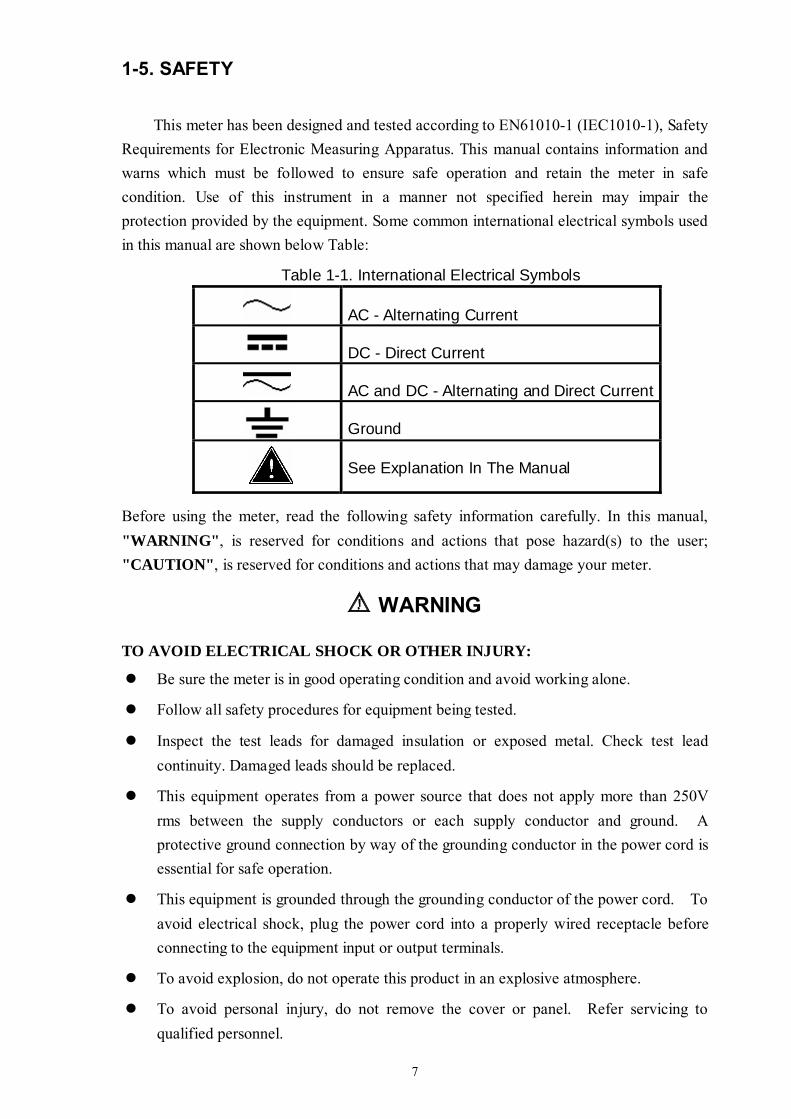
1-5. SAFETY
This meter has been designed and tested according to EN61010-1 (IEC1010-1), Safety Requirements for Electronic Measuring Apparatus. This manual contains information and warns which must be followed to ensure safe operation and retain the meter in safe condition. Use of this instrument in a manner not specified herein may impair the protection provided by the equipment. Some common international electrical symbols used in this manual are shown below Table:
Table 1-1. International Electrical Symbols
AC - Alternating Current
DC - Direct Current
AC and DC - Alternating and Direct Current
Ground
See Explanation In The Manual
Before using the meter, read the following safety information carefully. In this manual, "WARNING", is reserved for conditions and actions that pose hazard(s) to the user; "CAUTION", is reserved for conditions and actions that may damage your meter.
WARNING
TO AVOID ELECTRICAL SHOCK OR OTHER INJURY:
Be sure the meter is in good operating condition and avoid working alone.
Follow all safety procedures for equipment being tested.
Inspect the test leads for damaged insulation or exposed metal. Check test lead continuity. Damaged leads should be replaced.
This equipment operates from a power source that does not apply more than 250V rms between the supply conductors or each supply conductor and ground. A protective ground connection by way of the grounding conductor in the power cord is essential for safe operation.
This equipment is grounded through the grounding conductor of the power cord. To avoid electrical shock, plug the power cord into a properly wired receptacle before connecting to the equipment input or output terminals.
To avoid explosion, do not operate this product in an explosive atmosphere.
To avoid personal injury, do not remove the cover or panel. Refer servicing to qualified personnel.

8
Select the proper function for your measurement.
To avoid electrical shock, use caution when working above 60V dc or 30V ac RMS.
Disconnect the live test lead before disconnecting the common test lead.
Disconnect the power and discharge high-voltage capacitors before testing in Ω and diode.
When making a current measurement, turn the circuit power off before connecting the meter in the circuit.
To avoid fire hazard, always use a specified fuse.
Use clamp-on probes when measuring circuits exceeding 10 amps.
When servicing the meter, use only the replacement parts specified.
Do not allow meter to be used if it is damaged or if its safety is impaired.
The meter is safety-certified in compliance with EN61010-1 and EN61010-2-31 (IEC1010-1 & IEC1010-2-31) Installation Category ΙΙI 600V and CAT II 1000V Pollution Degree 2. In order to maintain its insulation properties, please be sure to use with the standard or compatible test probes.
CE requirement: Under the influence of R.F field according to standard, the supplied test leads will pick up induced noise. To have better shielding effect, a short-twisted lead should be used.
9
Section 2
Getting Started 2-1 Introduction
Section 2 describes the front panel operational keys, displays, input terminals and rear panel of the meter, adjusting handle, explains general operating features.
2-2 Getting Started Unpacking and Inspecting the Meter
Carefully remove the meter from its shipping container and inspect it for possible damage or missing items. If the meter is damaged or something is missing, contact the place of purchase immediately. Save the container and packing material in case user has to return the meter.
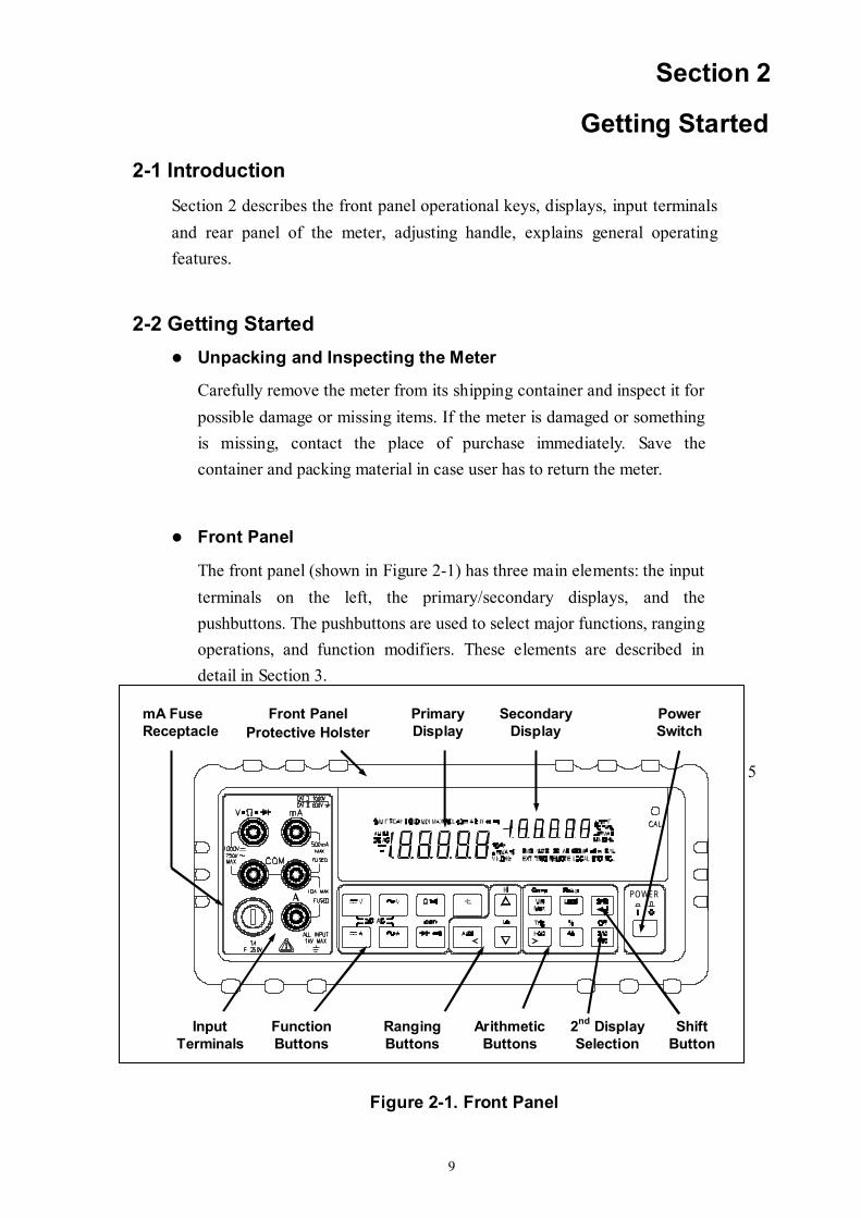
Front Panel
The front panel (shown in Figure 2-1) has three main elements: the input terminals on the left, the primary/secondary displays, and the pushbuttons. The pushbuttons are used to select major functions, ranging operations, and function modifiers. These elements are described in detail in Section 3.
POWER
Figure 2-1. Front Panel
5
Input Terminals
Primary Display
Secondary Display
Function Buttons
Ranging Buttons
Arithmetic Buttons
Shift Button
Power Switch
2nd Display Selection
mA Fuse Receptacle
Front Panel Protective Holster
10
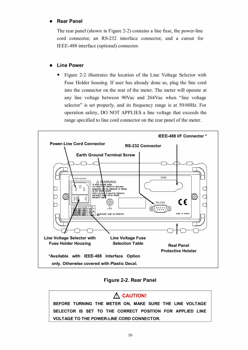
Rear Panel
The rear panel (shown in Figure 2-2) contains a line fuse, the power-line cord connector, an RS-232 interface connector, and a cutout for IEEE-488 interface (optional) connector.
Line Power
Figure 2-2 illustrates the location of the Line Voltage Selector with Fuse Holder housing. If user has already done so, plug the line cord into the connector on the rear of the meter. The meter will operate at any line voltage between 90Vac and 264Vac when “line voltage selector” is set properly, and its frequency range is at 50/60Hz. For operation safety, DO NOT APPLIES a line voltage that exceeds the range specified to line cord connector on the rear panel of the meter.
~LINE VOLTAGE FUSE
16VA 50-60Hz
WARNING
RS-232C
GPIB
Figure 2-2. Rear Panel
CAUTION! BEFORE TURNING THE METER ON, MAKE SURE THE LINE VOLTAGE
SELECTOR IS SET TO THE CORRECT POSITION FOR APPLIED LINE
VOLTAGE TO THE POWER-LINE CORD CONNECTOR.
Line Voltage Selector with Fuse Holder Housing
Line Voltage Fuse Selection Table
Power-Line Cord Connector RS-232 Connector
IEEE-488 I/F Connector *
*Available with IEEE-488 Interface Option
only. Otherwise covered with Plastic Decal.
Earth Ground Terminal Screw
Real Panel Protective Holster
11
The “line voltage selector” is settable for 100Vac, 120Vac, 220Vac, and 240Vac line voltages.
The correct fuse ratings: 250mA fuse for 100Vac or 120Vac is selected, and 125mA fuse for 220Vac or 240Vac is selected.
Case, Panels and Holsters To avoid electric shock or injury, do not operate the meter without panels or case in place.
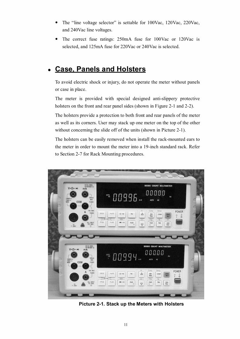
The meter is provided with special designed anti-slippery protective holsters on the front and rear panel sides (shown in Figure 2-1 and 2-2).
The holsters provide a protection to both front and rear panels of the meter as well as its corners. User may stack up one meter on the top of the other without concerning the slide off of the units (shown in Picture 2-1).
The holsters can be easily removed when install the rack-mounted ears to the meter in order to mount the meter into a 19-inch standard rack. Refer to Section 2-7 for Rack Mounting procedures.
Picture 2-1. Stack up the Meters with Holsters
12
Grounding the Meter The meter is grounded through power cord. To avoid electric shock or injury, grounding wire in the power line cord must be connected.
Operating in Explosive Atmospheres The meter does not provide explosion protection for explosive gasses or arcing components. Do not operate the meter in such circumstances.
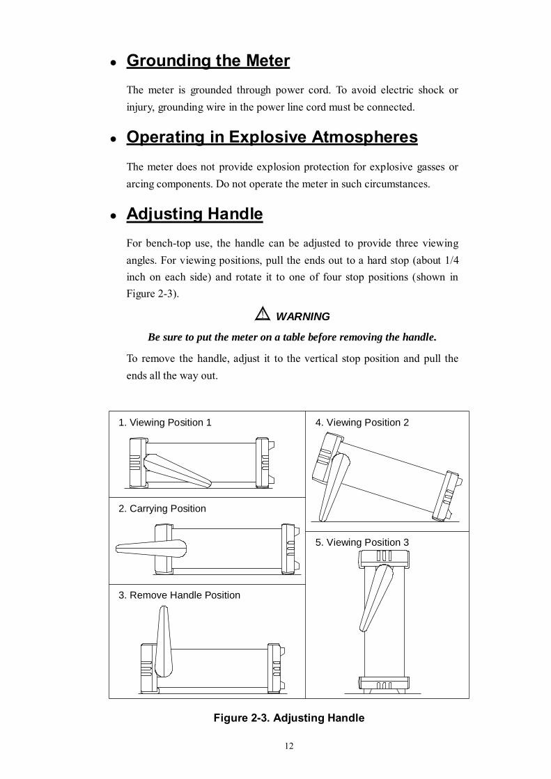
Adjusting Handle For bench-top use, the handle can be adjusted to provide three viewing angles. For viewing positions, pull the ends out to a hard stop (about 1/4 inch on each side) and rotate it to one of four stop positions (shown in Figure 2-3).
WARNING
Be sure to put the meter on a table before removing the handle.
To remove the handle, adjust it to the vertical stop position and pull the ends all the way out.
3. Remove Handle Position
2. Carrying Position
1. Viewing Position 1 4. Viewing Position 2
5. Viewing Position 3
Figure 2-3. Adjusting Handle

13
2-3 Turning the Meter ON To turn the meter on, press the Power button to “IN” position located on the lower right of the front panel. When the meter is turned on, the primary and secondary displays light for about 2 seconds while an internal self-test running by its digital circuitry. If the Hold button is pressed while the power-up sequence is in progress, all segments and annunciators of the entire display remain on until another button is pressed. Then the power-up sequence continues. After the meter completing its power-up sequence, it resumes the power-up measurement configuration stored in non-volatile memory. The power-up default configuration status set at factory is shown in Table 3-2.
2-4 Selecting Current Input Terminals and Measurement Range If current (dc or ac) is being measured in the Auto-ranging mode, with a signal input on the 500mA terminal, the meter will select the range 500μA~500mA automatically.
If a signal input is applied to the 10A input terminal, the meter will select the 5A or 10A range automatically.
2-5 Using the Pushbuttons The meter functions and operations can be selected by pressing the pushbuttons on the front panel select.
A summary of pushbuttons is shown in Figure 2-4.
Pushbuttons can be used in three ways. User can: Press a single button to select a function or operation.
EXAMPLE:
(Press) to select AC voltage measurement for the primary display.
Press a combination of buttons, one after the other.
EXAMPLE:
then followed by to select dBm calculation.
14
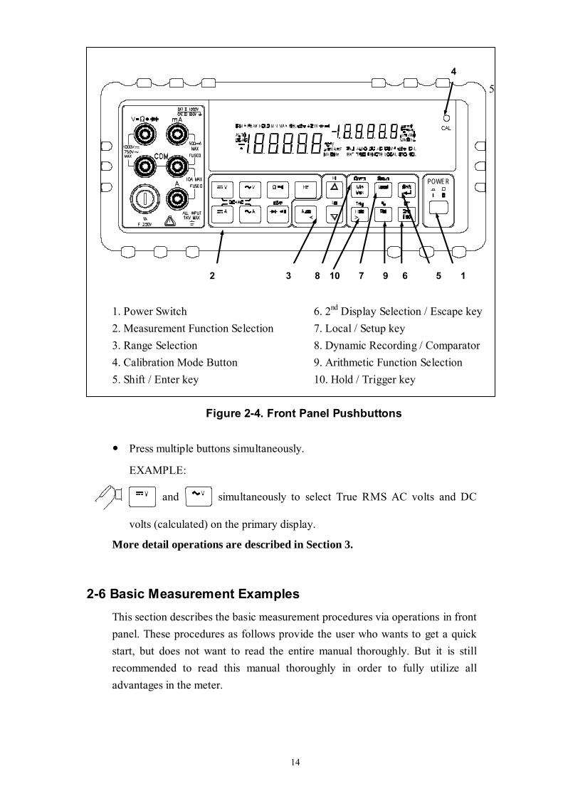
POWER
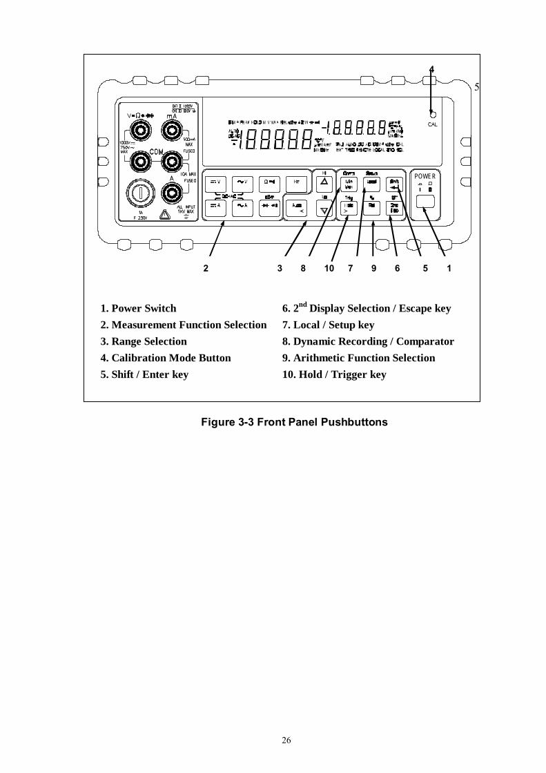
1. Power Switch 6. 2nd Display Selection / Escape key 2. Measurement Function Selection 7. Local / Setup key 3. Range Selection 8. Dynamic Recording / Comparator 4. Calibration Mode Button 9. Arithmetic Function Selection 5. Shift / Enter key 10. Hold / Trigger key
Figure 2-4. Front Panel Pushbuttons
Press multiple buttons simultaneously.
EXAMPLE:
and simultaneously to select True RMS AC volts and DC
volts (calculated) on the primary display.
More detail operations are described in Section 3. 2-6 Basic Measurement Examples
This section describes the basic measurement procedures via operations in front panel. These procedures as follows provide the user who wants to get a quick start, but does not want to read the entire manual thoroughly. But it is still recommended to read this manual thoroughly in order to fully utilize all advantages in the meter.
5
2 3 8 10 7 9 6 5 1
4
15
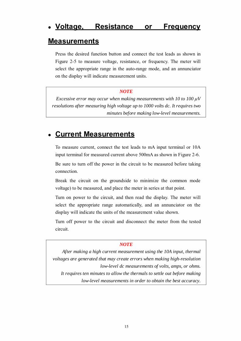
Voltage, Resistance or Frequency
Measurements Press the desired function button and connect the test leads as shown in Figure 2-5 to measure voltage, resistance, or frequency. The meter will select the appropriate range in the auto-range mode, and an annunciator on the display will indicate measurement units.
NOTE Excessive error may occur when making measurements with 10 to 100 μV
resolutions after measuring high voltage up to 1000 volts dc. It requires two minutes before making low-level measurements.
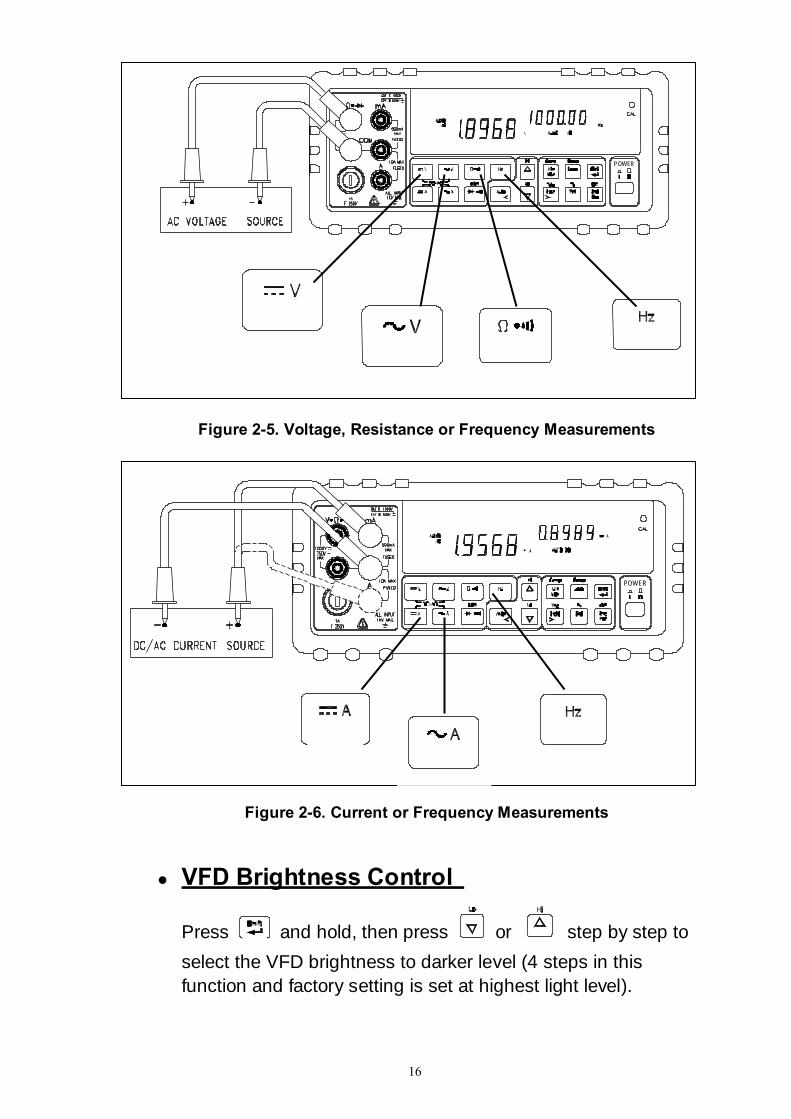
Current Measurements To measure current, connect the test leads to mA input terminal or 10A input terminal for measured current above 500mA as shown in Figure 2-6.
Be sure to turn off the power in the circuit to be measured before taking connection.
Break the circuit on the groundside to minimize the common mode voltage) to be measured, and place the meter in series at that point.
Turn on power to the circuit, and then read the display. The meter will select the appropriate range automatically, and an annunciator on the display will indicate the units of the measurement value shown.
Turn off power to the circuit and disconnect the meter from the tested circuit.
NOTE After making a high current measurement using the 10A input, thermal
voltages are generated that may create errors when making high-resolution low-level dc measurements of volts, amps, or ohms.
It requires ten minutes to allow the thermals to settle out before making low-level measurements in order to obtain the best accuracy.
16
POWER
Figure 2-5. Voltage, Resistance or Frequency Measurements
POWER
Figure 2-6. Current or Frequency Measurements
VFD Brightness Control
Press and hold, then press or step by step to select the VFD brightness to darker level (4 steps in this function and factory setting is set at highest light level).
17
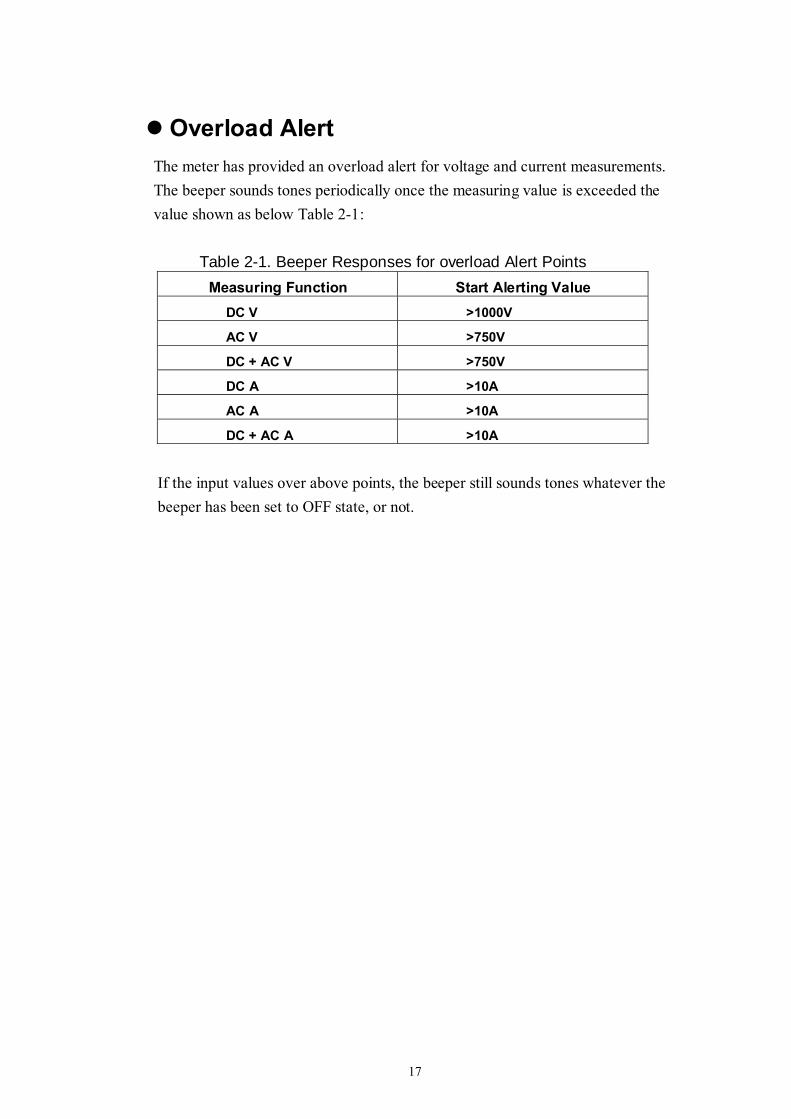
Overload Alert The meter has provided an overload alert for voltage and current measurements. The beeper sounds tones periodically once the measuring value is exceeded the value shown as below Table 2-1:
Table 2-1. Beeper Responses for overload Alert Points Measuring Function Start Alerting Value
DC V >1000V
AC V >750V
DC + AC V >750V
DC A >10A
AC A >10A
DC + AC A >10A
If the input values over above points, the beeper still sounds tones whatever the beeper has been set to OFF state, or not.
18
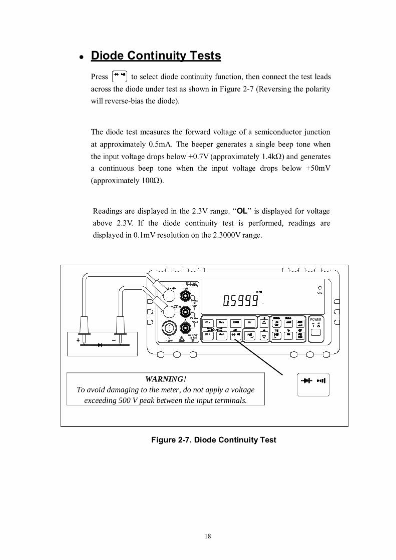
Diode Continuity Tests Press to select diode continuity function, then connect the test leads across the diode under test as shown in Figure 2-7 (Reversing the polarity will reverse-bias the diode).
The diode test measures the forward voltage of a semiconductor junction at approximately 0.5mA. The beeper generates a single beep tone when the input voltage drops below +0.7V (approximately 1.4kΩ) and generates a continuous beep tone when the input voltage drops below +50mV (approximately 100Ω).
Readings are displayed in the 2.3V range. “OL” is displayed for voltage above 2.3V. If the diode continuity test is performed, readings are displayed in 0.1mV resolution on the 2.3000V range.
POWER
Figure 2-7. Diode Continuity Test
WARNING! To avoid damaging to the meter, do not apply a voltage
exceeding 500 V peak between the input terminals.
19
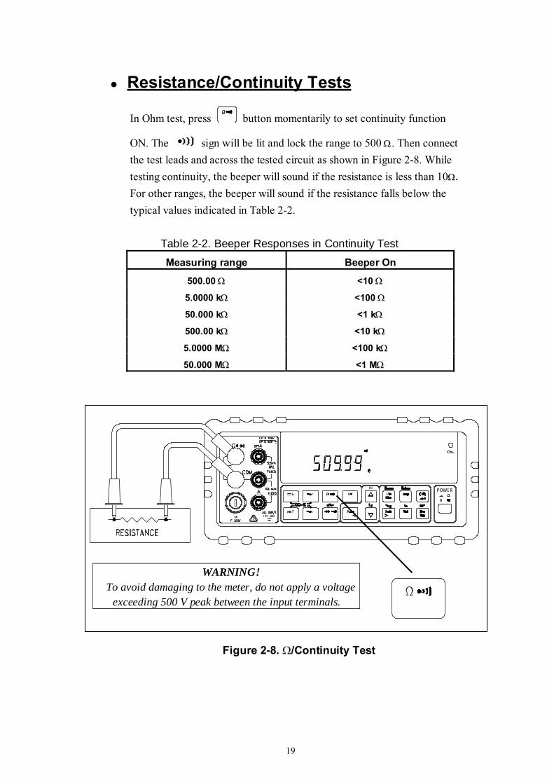
Resistance/Continuity Tests
In Ohm test, press button momentarily to set continuity function
ON. The sign will be lit and lock the range to 500 Ω. Then connect the test leads and across the tested circuit as shown in Figure 2-8. While testing continuity, the beeper will sound if the resistance is less than 10Ω. For other ranges, the beeper will sound if the resistance falls below the typical values indicated in Table 2-2.
Table 2-2. Beeper Responses in Continuity Test
Measuring range Beeper On
500.00 Ω <10 Ω
5.0000 kΩ <100 Ω
50.000 kΩ <1 kΩ
500.00 kΩ <10 kΩ
5.0000 MΩ <100 kΩ
50.000 MΩ <1 MΩ
POWER
Figure 2-8. Ω/Continuity Test
WARNING! To avoid damaging to the meter, do not apply a voltage
exceeding 500 V peak between the input terminals.
20
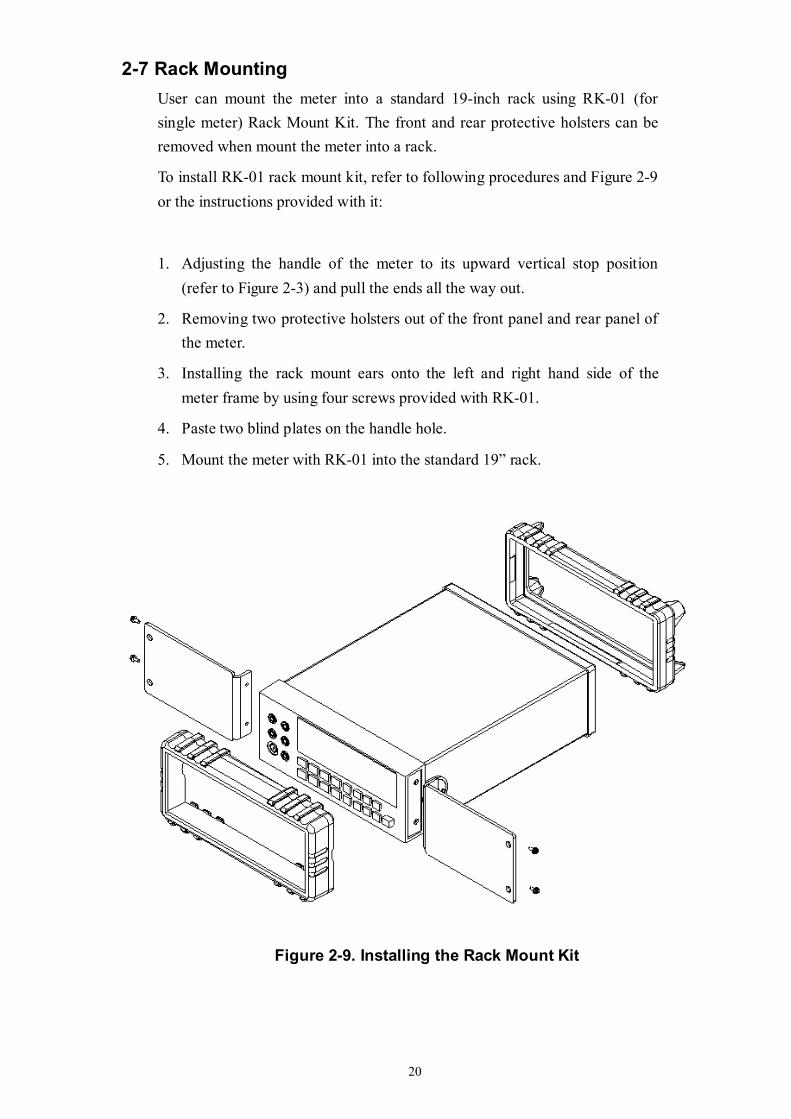
2-7 Rack Mounting User can mount the meter into a standard 19-inch rack using RK-01 (for single meter) Rack Mount Kit. The front and rear protective holsters can be removed when mount the meter into a rack.
To install RK-01 rack mount kit, refer to following procedures and Figure 2-9 or the instructions provided with it:
1. Adjusting the handle of the meter to its upward vertical stop position (refer to Figure 2-3) and pull the ends all the way out.
2. Removing two protective holsters out of the front panel and rear panel of the meter.
3. Installing the rack mount ears onto the left and right hand side of the meter frame by using four screws provided with RK-01.
4. Paste two blind plates on the handle hole.
5. Mount the meter with RK-01 into the standard 19” rack.
Figure 2-9. Installing the Rack Mount Kit
21
Section 3
Front Panel Operation 3-1 Introduction
This section provides a complete description of each operation that can be performed by using the pushbuttons on the front panel.
All related information for operations and functions are grouped together.
3-2 Front Panel Operations
The following operations can be performed from the front panel:
Select a measuring function (Vdc, Vac, Adc, Aac, resistance/continuity, frequency, and diode continuity test) for the primary display.
Base on primary display press to select the related function for
secondary display.
Take a measurement and display a reading.
Select the manual or auto-range mode (AUTO)
Manually select a measuring range for the primary display.
Select function modifier that cause the meter to display relative readings (REL), minimum or maximum values (MIN MAX) or decibels (dBm and dB), or to enter the Data Hold mode or Refresh Hold (HOLD) to hold a reading on the primary display.
Set the dB reference impedance (REFΩ).
Take a measurement and compare (COMP) it against a tolerance range (Hi, Lo, or Pass).
Take a measurement and percentage (%) display.
Select the brightness for VFD display.
Use the ”editor” to select from option list, to enter a HI-LO range for the compare mode and percentage mode.
Configure the computer interface (RS-232 or IEEE-488).
Send measurement directly to a printer or terminal through the RS-232 interface (RS-232 print only mode)
These and other front panel operations are described in the remainder of Section 3.
22
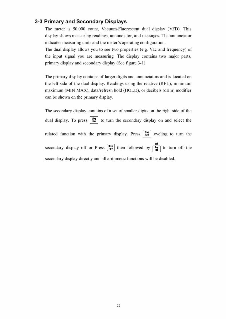
3-3 Primary and Secondary Displays The meter is 50,000 count, Vacuum-Fluorescent dual display (VFD). This display shows measuring readings, annunciator, and messages. The annunciator indicates measuring units and the meter’s operating configuration. The dual display allows you to see two properties (e.g. Vac and frequency) of the input signal you are measuring. The display contains two major parts, primary display and secondary display (See figure 3-1). The primary display contains of larger digits and annunciators and is located on the left side of the dual display. Readings using the relative (REL), minimum maximum (MIN MAX), data/refresh hold (HOLD), or decibels (dBm) modifier can be shown on the primary display. The secondary display contains of a set of smaller digits on the right side of the
dual display. To press to turn the secondary display on and select the
related function with the primary display. Press cycling to turn the
secondary display off or Press then followed by to turn off the
secondary display directly and all arithmetic functions will be disabled.
23
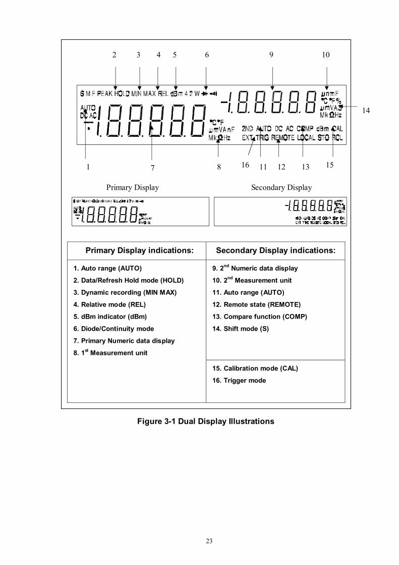
Primary Display Secondary Display
Primary Display indications: Secondary Display indications:
9. 2nd Numeric data display
10. 2nd Measurement unit
11. Auto range (AUTO)
12. Remote state (REMOTE)
13. Compare function (COMP)
14. Shift mode (S)
1. Auto range (AUTO)
2. Data/Refresh Hold mode (HOLD)
3. Dynamic recording (MIN MAX)
4. Relative mode (REL)
5. dBm indicator (dBm)
6. Diode/Continuity mode
7. Primary Numeric data display
8. 1st Measurement unit
15. Calibration mode (CAL)
16. Trigger mode
Figure 3-1 Dual Display Illustrations
1 7 8 11 12 13 15
2 3 4 5 6 9 10
14
16
24
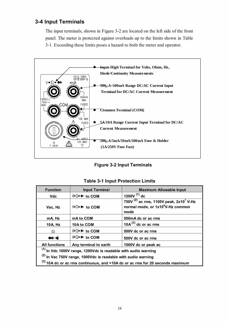
3-4 Input Terminals The input terminals, shown in Figure 3-2 are located on the left side of the front panel. The meter is protected against overloads up to the limits shown in Table 3-1. Exceeding these limits poses a hazard to both the meter and operator.
Figure 3-2 Input Terminals
Table 3-1 Input Protection Limits
Function Input Terminal Maximum Allowable Input Vdc to COM 1200V (1) dc
Vac, Hz to COM 750V (2) ac rms, 1100V peak, 2x10⁷ V-Hz normal mode, or 1x10⁶V-Hz common mode
mA, Hz mA to COM 500mA dc or ac rms 10A, Hz 10A to COM 10A (3) dc or ac rms
Ω to COM 500V dc or ac rms
to COM 500V dc or ac rms All functions Any terminal to earth 1000V dc or peak ac (1) In Vdc 1000V range, 1200Vdc is readable with audio warning (2) In Vac 750V range, 1000Vdc is readable with audio warning (3) 10A dc or ac rms continuous, and >10A dc or ac rms for 20 seconds maximum
Input-High Terminal for Volts, Ohms, Hz, Diode/Continuity Measurements
500μA~500mA Range DC/AC Current Input Terminal for DC/AC Current Measurement
Common Terminal (COM)
5A/10A Range Current Input Terminal for DC/AC Current Measurement
500μA/5mA/50mA/500mA Fuse & Holder (1A/250V Fuse Fast)
25
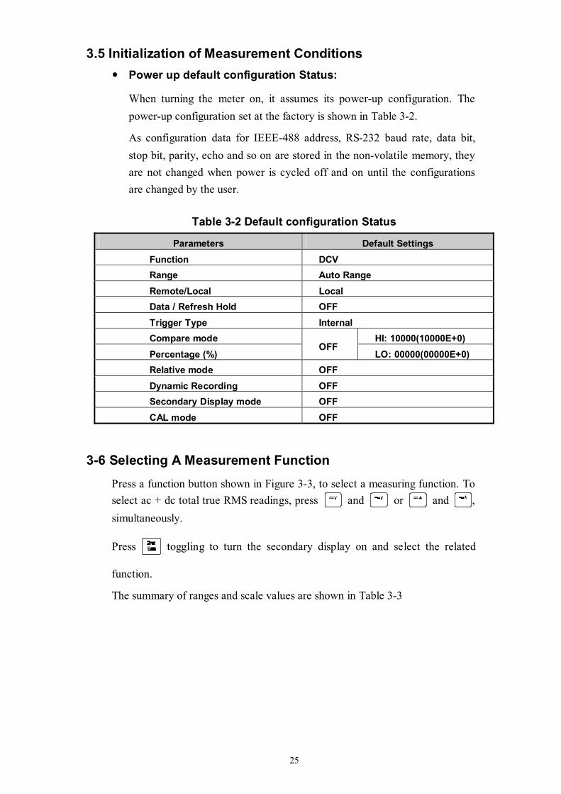
3.5 Initialization of Measurement Conditions Power up default configuration Status:
When turning the meter on, it assumes its power-up configuration. The power-up configuration set at the factory is shown in Table 3-2.
As configuration data for IEEE-488 address, RS-232 baud rate, data bit, stop bit, parity, echo and so on are stored in the non-volatile memory, they are not changed when power is cycled off and on until the configurations are changed by the user.
Table 3-2 Default configuration Status
Parameters Default Settings Function DCV Range Auto Range Remote/Local Local Data / Refresh Hold OFF Trigger Type Internal Compare mode HI: 10000(10000E+0) Percentage (%)
OFF LO: 00000(00000E+0)
Relative mode OFF Dynamic Recording OFF Secondary Display mode OFF CAL mode OFF
3-6 Selecting A Measurement Function
Press a function button shown in Figure 3-3, to select a measuring function. To select ac + dc total true RMS readings, press and or and , simultaneously.
Press toggling to turn the secondary display on and select the related
function.
The summary of ranges and scale values are shown in Table 3-3
26
POWER
1. Power Switch 6. 2nd Display Selection / Escape key 2. Measurement Function Selection 7. Local / Setup key 3. Range Selection 8. Dynamic Recording / Comparator 4. Calibration Mode Button 9. Arithmetic Function Selection 5. Shift / Enter key 10. Hold / Trigger key
Figure 3-3 Front Panel Pushbuttons
5
2 3 8 10 7 9 6 5 1
4
27
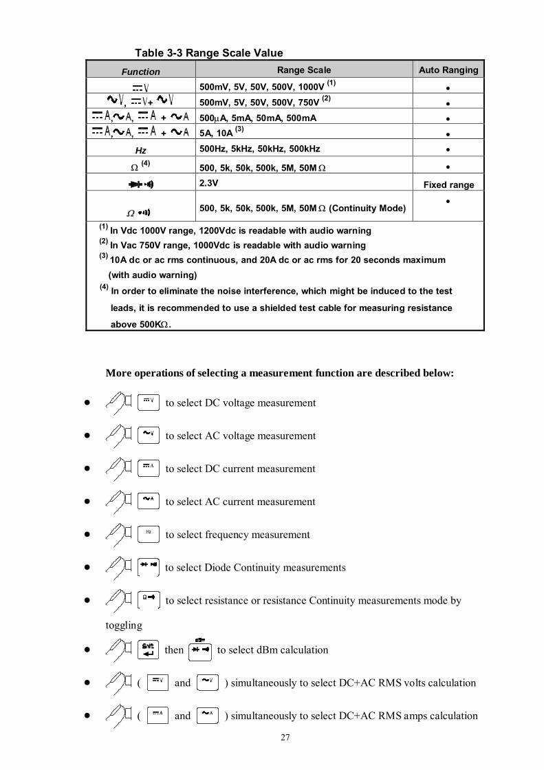
Table 3-3 Range Scale Value Function Range Scale Auto Ranging
500mV, 5V, 50V, 500V, 1000V (1) • , + 500mV, 5V, 50V, 500V, 750V (2) •
, , + 500μA, 5mA, 50mA, 500mA • , , + 5A, 10A (3) •
Hz 500Hz, 5kHz, 50kHz, 500kHz •
Ω (4) 500, 5k, 50k, 500k, 5M, 50M Ω •
2.3V Fixed range
Ω . 500, 5k, 50k, 500k, 5M, 50M Ω (Continuity Mode) •
(1) In Vdc 1000V range, 1200Vdc is readable with audio warning (2) In Vac 750V range, 1000Vdc is readable with audio warning (3) 10A dc or ac rms continuous, and 20A dc or ac rms for 20 seconds maximum (with audio warning)
(4) In order to eliminate the noise interference, which might be induced to the test
leads, it is recommended to use a shielded test cable for measuring resistance
above 500KΩ.
More operations of selecting a measurement function are described below:
to select DC voltage measurement
to select AC voltage measurement
to select DC current measurement
to select AC current measurement
to select frequency measurement
to select Diode Continuity measurements
to select resistance or resistance Continuity measurements mode by
toggling
then to select dBm calculation
( and ) simultaneously to select DC+AC RMS volts calculation
( and ) simultaneously to select DC+AC RMS amps calculation
28
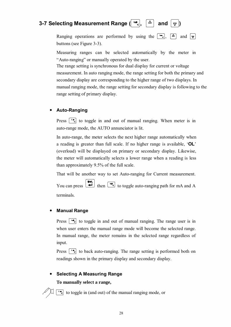
3-7 Selecting Measurement Range ( , and )
Ranging operations are performed by using the , and buttons (see Figure 3-3).
Measuring ranges can be selected automatically by the meter in “Auto-ranging” or manually operated by the user. The range setting is synchronous for dual display for current or voltage measurement. In auto ranging mode, the range setting for both the primary and secondary display are corresponding to the higher range of two displays. In manual ranging mode, the range setting for secondary display is following to the range setting of primary display.
Auto-Ranging
Press to toggle in and out of manual ranging. When meter is in auto-range mode, the AUTO annunciator is lit.
In auto-range, the meter selects the next higher range automatically when a reading is greater than full scale. If no higher range is available, ‘OL’ (overload) will be displayed on primary or secondary display. Likewise, the meter will automatically selects a lower range when a reading is less than approximately 9.5% of the full scale.
That will be another way to set Auto-ranging for Current measurement.
You can press then to toggle auto-ranging path for mA and A
terminals.
Manual Range
Press to toggle in and out of manual ranging. The range user is in when user enters the manual range mode will become the selected range. In manual range, the meter remains in the selected range regardless of input.
Press to back auto-ranging. The range setting is performed both on readings shown in the primary display and secondary display.
Selecting A Measuring Range
To manually select a range,
to toggle in (and out) of the manual ranging mode, or
29
or to select higher range or lower range directly.
In manual range mode,
or to select higher range or lower range to the desired one.
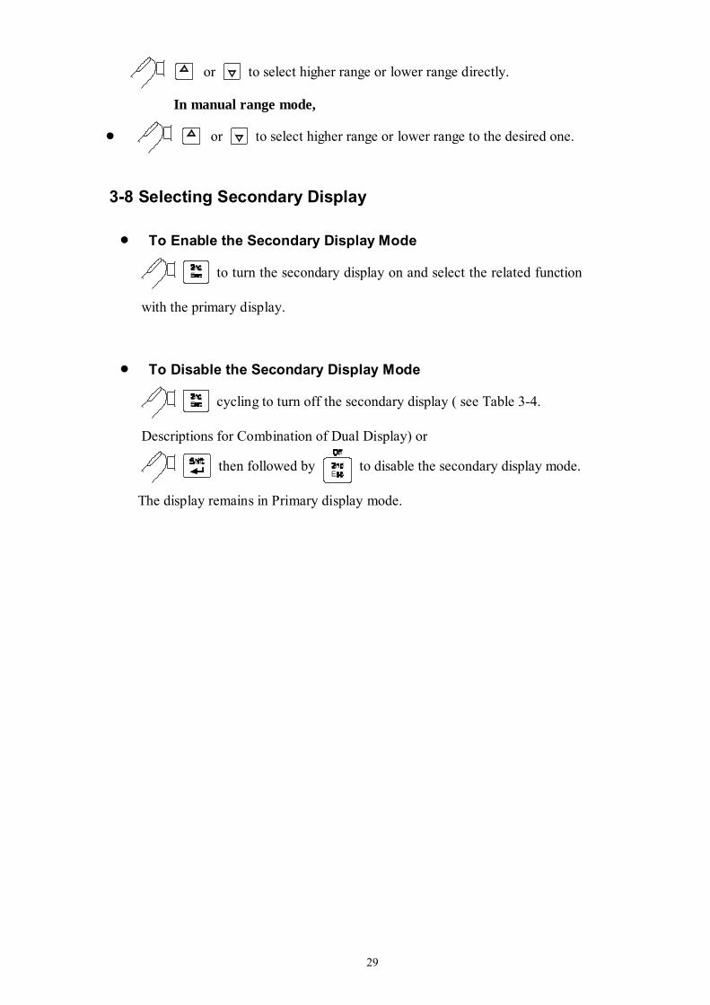
3-8 Selecting Secondary Display
To Enable the Secondary Display Mode
to turn the secondary display on and select the related function
with the primary display.
To Disable the Secondary Display Mode
cycling to turn off the secondary display ( see Table 3-4.
Descriptions for Combination of Dual Display) or
then followed by to disable the secondary display mode.
The display remains in Primary display mode.
30
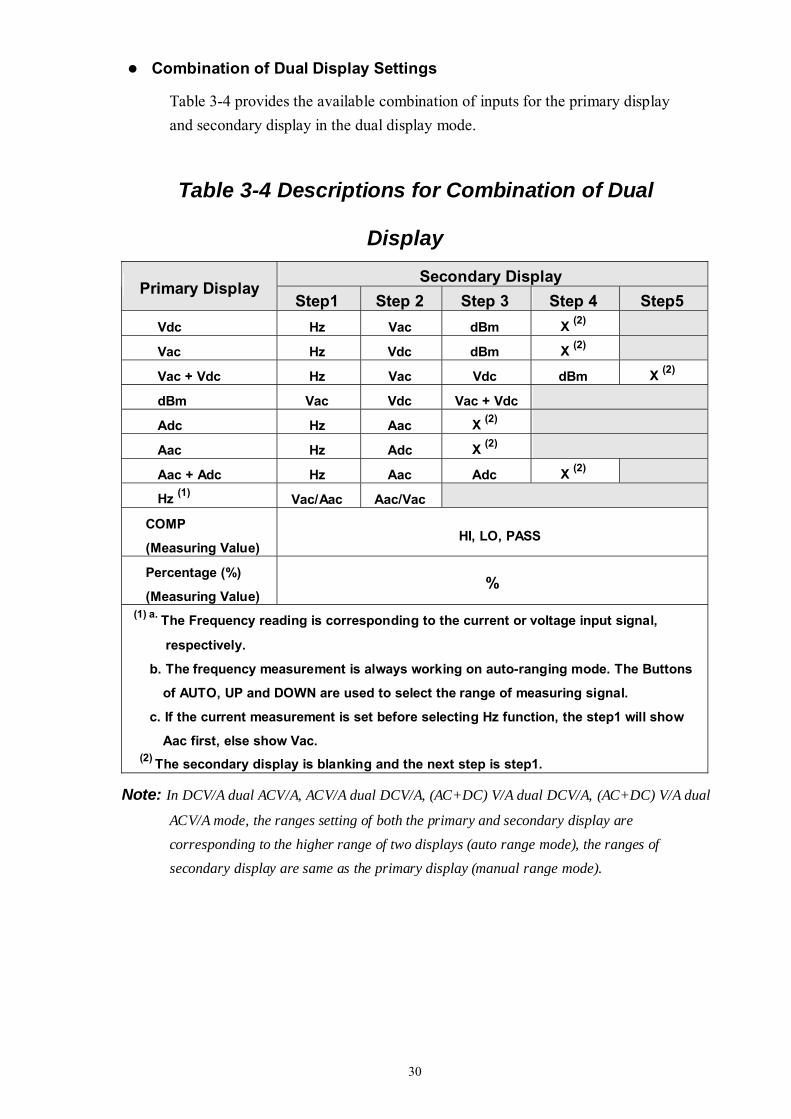
Combination of Dual Display Settings
Table 3-4 provides the available combination of inputs for the primary display and secondary display in the dual display mode.
Table 3-4 Descriptions for Combination of Dual
Display Secondary Display
Primary Display Step1 Step 2 Step 3 Step 4 Step5
Vdc Hz Vac dBm X (2)
Vac Hz Vdc dBm X (2)
Vac + Vdc Hz Vac Vdc dBm X (2)
dBm Vac Vdc Vac + Vdc
Adc Hz Aac X (2)
Aac Hz Adc X (2)
Aac + Adc Hz Aac Adc X (2)
Hz (1) Vac/Aac Aac/Vac
COMP
(Measuring Value) HI, LO, PASS
Percentage (%)
(Measuring Value) %
(1) a. The Frequency reading is corresponding to the current or voltage input signal,
respectively.
b. The frequency measurement is always working on auto-ranging mode. The Buttons
of AUTO, UP and DOWN are used to select the range of measuring signal.
c. If the current measurement is set before selecting Hz function, the step1 will show
Aac first, else show Vac. (2) The secondary display is blanking and the next step is step1.
Note: In DCV/A dual ACV/A, ACV/A dual DCV/A, (AC+DC) V/A dual DCV/A, (AC+DC) V/A dual
ACV/A mode, the ranges setting of both the primary and secondary display are corresponding to the higher range of two displays (auto range mode), the ranges of secondary display are same as the primary display (manual range mode).
31
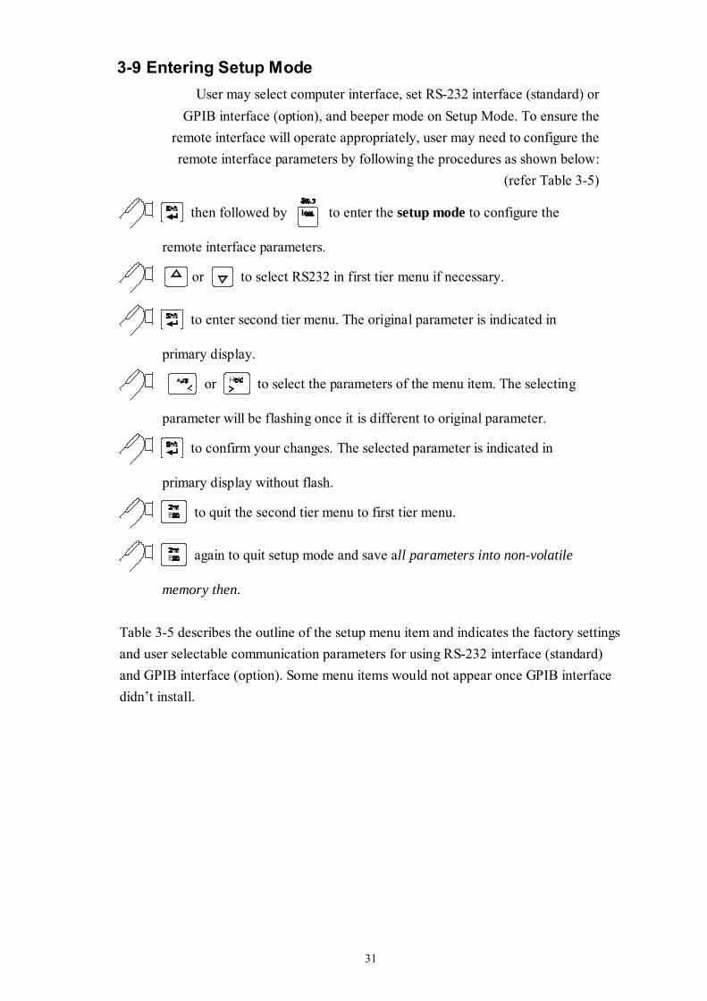
3-9 Entering Setup Mode User may select computer interface, set RS-232 interface (standard) or
GPIB interface (option), and beeper mode on Setup Mode. To ensure the remote interface will operate appropriately, user may need to configure the remote interface parameters by following the procedures as shown below:
(refer Table 3-5)
then followed by to enter the setup mode to configure the
remote interface parameters.
or to select RS232 in first tier menu if necessary.
to enter second tier menu. The original parameter is indicated in
primary display.
or to select the parameters of the menu item. The selecting
parameter will be flashing once it is different to original parameter.
to confirm your changes. The selected parameter is indicated in
primary display without flash.
to quit the second tier menu to first tier menu.
again to quit setup mode and save all parameters into non-volatile
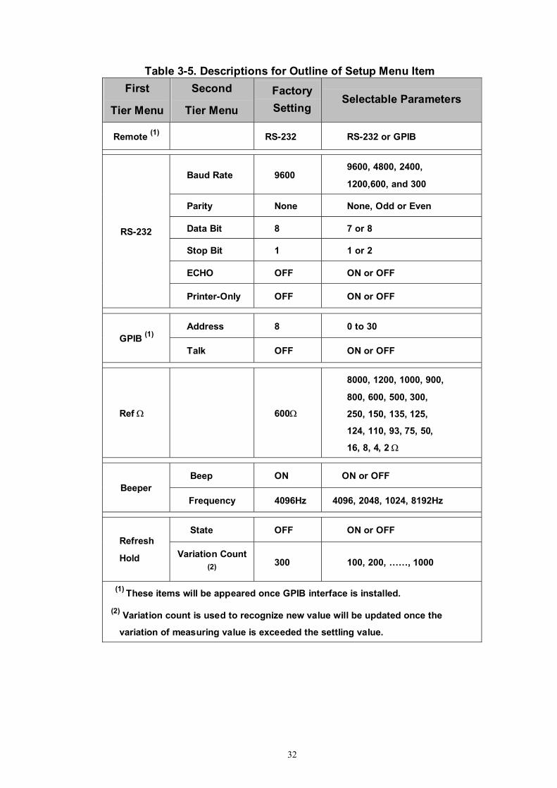
memory then. Table 3-5 describes the outline of the setup menu item and indicates the factory settings and user selectable communication parameters for using RS-232 interface (standard) and GPIB interface (option). Some menu items would not appear once GPIB interface didn’t install.
32
Table 3-5. Descriptions for Outline of Setup Menu Item First
Tier Menu
Second
Tier Menu
Factory Setting
Selectable Parameters
Remote (1) RS-232 RS-232 or GPIB
Baud Rate 9600 9600, 4800, 2400,
1200,600, and 300
Parity None None, Odd or Even
Data Bit 8 7 or 8
Stop Bit 1 1 or 2
ECHO OFF ON or OFF
RS-232
Printer-Only OFF ON or OFF
Address 8 0 to 30 GPIB (1)
Talk OFF ON or OFF
Ref Ω 600Ω
8000, 1200, 1000, 900,
800, 600, 500, 300,
250, 150, 135, 125,
124, 110, 93, 75, 50,
16, 8, 4, 2 Ω
Beep ON ON or OFF Beeper
Frequency 4096Hz 4096, 2048, 1024, 8192Hz
State OFF ON or OFF Refresh
Hold Variation Count (2)
300 100, 200, ……, 1000
(1) These items will be appeared once GPIB interface is installed.
(2) Variation count is used to recognize new value will be updated once the
variation of measuring value is exceeded the settling value.
33
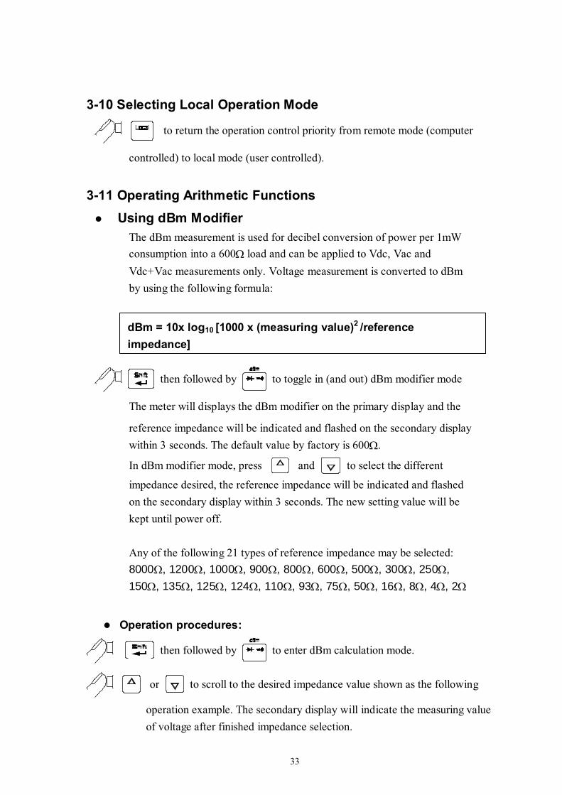
3-10 Selecting Local Operation Mode
to return the operation control priority from remote mode (computer
controlled) to local mode (user controlled).
3-11 Operating Arithmetic Functions Using dBm Modifier
The dBm measurement is used for decibel conversion of power per 1mW consumption into a 600Ω load and can be applied to Vdc, Vac and Vdc+Vac measurements only. Voltage measurement is converted to dBm by using the following formula:
then followed by to toggle in (and out) dBm modifier mode
The meter will displays the dBm modifier on the primary display and the
reference impedance will be indicated and flashed on the secondary display within 3 seconds. The default value by factory is 600Ω.
In dBm modifier mode, press and to select the different
impedance desired, the reference impedance will be indicated and flashed on the secondary display within 3 seconds. The new setting value will be kept until power off. Any of the following 21 types of reference impedance may be selected: 8000Ω, 1200Ω, 1000Ω, 900Ω, 800Ω, 600Ω, 500Ω, 300Ω, 250Ω, 150Ω, 135Ω, 125Ω, 124Ω, 110Ω, 93Ω, 75Ω, 50Ω, 16Ω, 8Ω, 4Ω, 2Ω
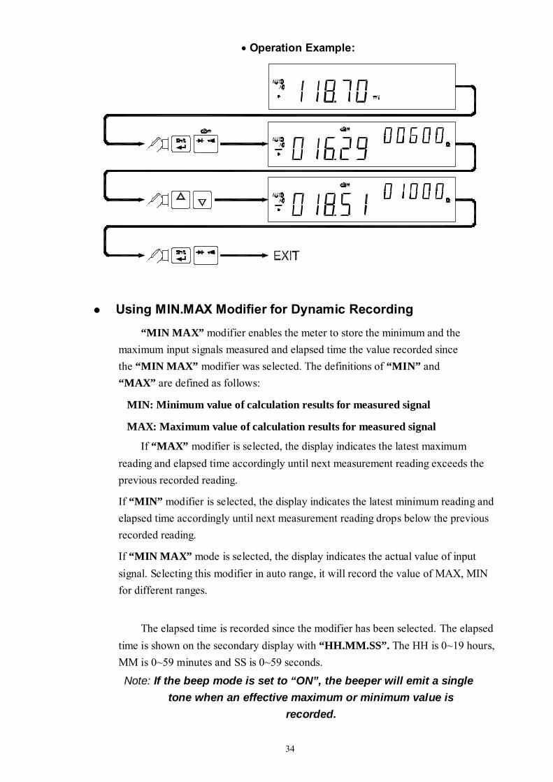
Operation procedures:
then followed by to enter dBm calculation mode.
or to scroll to the desired impedance value shown as the following
operation example. The secondary display will indicate the measuring value of voltage after finished impedance selection.
dBm = 10x log10 [1000 x (measuring value)2 /reference impedance]
34
• Operation Example:
Using MIN.MAX Modifier for Dynamic Recording
“MIN MAX” modifier enables the meter to store the minimum and the maximum input signals measured and elapsed time the value recorded since the “MIN MAX” modifier was selected. The definitions of “MIN” and “MAX” are defined as follows:
MIN: Minimum value of calculation results for measured signal
MAX: Maximum value of calculation results for measured signal
If “MAX” modifier is selected, the display indicates the latest maximum reading and elapsed time accordingly until next measurement reading exceeds the previous recorded reading.
If “MIN” modifier is selected, the display indicates the latest minimum reading and elapsed time accordingly until next measurement reading drops below the previous recorded reading.
If “MIN MAX” mode is selected, the display indicates the actual value of input signal. Selecting this modifier in auto range, it will record the value of MAX, MIN for different ranges.
The elapsed time is recorded since the modifier has been selected. The elapsed time is shown on the secondary display with “HH.MM.SS”. The HH is 0~19 hours, MM is 0~59 minutes and SS is 0~59 seconds.
Note: If the beep mode is set to “ON”, the beeper will emit a single tone when an effective maximum or minimum value is
recorded.
35
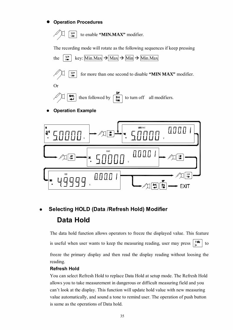
Operation Procedures
to enable “MIN.MAX” modifier.
The recording mode will rotate as the following sequences if keep pressing
the key: Min.Max Max Min Min.Max
for more than one second to disable “MIN MAX” modifier.
Or
then followed by to turn off all modifiers.
Operation Example
Selecting HOLD (Data /Refresh Hold) Modifier
Data Hold
The data hold function allows operators to freeze the displayed value. This feature
is useful when user wants to keep the measuring reading, user may press to
freeze the primary display and then read the display reading without loosing the reading. Refresh Hold You can select Refresh Hold to replace Data Hold at setup mode. The Refresh Hold allows you to take measurement in dangerous or difficult measuring field and you can’t look at the display. This function will update hold value with new measuring value automatically, and sound a tone to remind user. The operation of push button is same as the operations of Data hold.
36
Press to enter Refresh Hold mode. The present value will be held and the
“HOLD ” will be lit. It will be ready to hold new measuring value once the variation of measuring value exceed the setting of variation count, and the “HOLD ” will be flashed. The hold value will be updated until the measuring value is stable, then stop flash and light “HOLD ” and sound a tone to remind user.
For voltage and current measurements, the holding value will not be updated when the reading below 500 counts. For resistance and diode measurements, the holding value will not be updated if the reading at “OL” or open state. The holding value may not be updated once the reading can’t reach stable state for all measurements.
Operation Procedures
to enable Data Hold mode, and the annunciator HOLD will be
shown on the primary display.
again to disable Data Hold mode.
Note: The Data Hold mode can be used for other arithmetic functions such as dBm, REL and Min / Max.
Selecting REL (Relative) Modifier The relative function subtracts a stored value from the primary display and indicates the result.
This function is used for primary display only.
Press momentarily to set the relative mode. This sets the display to
zero and stores the displayed reading as a reference value. The "REL" will be lit also. Both ranges of auto or manual can set relative mode. The relative mode can’t set when an overload has occurred. If the relative mode is set in auto-ranging condition, enable the COMP or Percentage function will clear the relative mode. You do need to set relative function again.
Press again to exit the relative mode.
37
Using COMP (Compare) Function “COMP” function compares the measurement inputs with the pre-set HI and LO limits. The compare function calculation expression is based on counts without decimal point.
HI: Measurement value > High (HI) limit value
LO: Measurement value < Low (LO) limit value
PASS: High limit value ≥ Measurement value ≥ Low limit value
When “COMP” function is enabled, the actual measuring value will be shown in primary display and a comparison result “HI”, “LO”, or “PASS” will be shown in secondary display.
The beeper will sound three tones as the result is changed from “PASS” to “HI” or “LO”, and one tone from “HI” or “LO” to “PASS”.
Notes:
1. The Compare function can be used with other arithmetic functions such as REL, MINMAX, and dBm modifiers
2. For frequency measurement, it will be locked to the range user is in when user enters this mode will become the selected range.
Operation Procedures
then followed by to enable the “COMP” function.
then followed by again to disable the “COMP” function.
Setting a Compare Limit / Percentage Value
Using the following procedure to set the HI and the LO limit values for “COMP” / “Percentage” function:
then followed by to enter the HI limit setup mode.
The HI limit will be shown in primary display.
, , or to change this value.
to store the HI limit value in counts.
then followed by and repeat the above steps to set and store
the LO limit value.

38
Note: 1. After set the Hi and/or the LO limits, the limits can be used for all ranges. However, at different range, the HI and the LO limits represent different values according to their respective counts.
The RIGHT and LEFT button is used to select which digit will be adjusted. Push the buttons to left shift or right shift five digits.
D5 D4 D3 D2 D1
D5D4D3D2D1
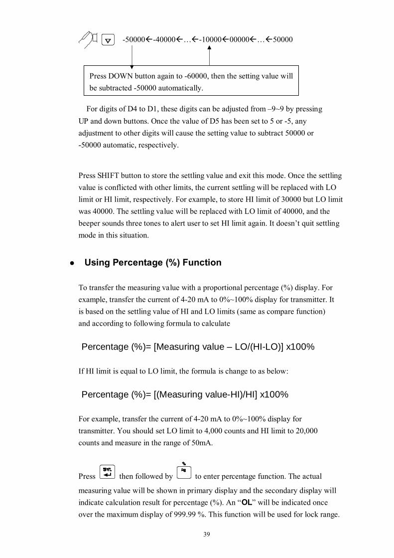
The UP and DOWN button is used to adjust the value, press UP or down button to increase or decrease one count for each digit, respectively. For the most significant digit (D5), its digital variation is shown as following:
-50000 -40000 … 00000 10000 … 50000
Press UP button again to 60000, then the setting value will be subtracted 50000 automatically.
39
-50000-40000…-1000000000…50000
For digits of D4 to D1, these digits can be adjusted from –9~9 by pressing UP and down buttons. Once the value of D5 has been set to 5 or -5, any adjustment to other digits will cause the setting value to subtract 50000 or -50000 automatic, respectively.
Press SHIFT button to store the settling value and exit this mode. Once the settling value is conflicted with other limits, the current settling will be replaced with LO limit or HI limit, respectively. For example, to store HI limit of 30000 but LO limit was 40000. The settling value will be replaced with LO limit of 40000, and the beeper sounds three tones to alert user to set HI limit again. It doesn’t quit settling mode in this situation.
Using Percentage (%) Function
To transfer the measuring value with a proportional percentage (%) display. For example, transfer the current of 4-20 mA to 0%~100% display for transmitter. It is based on the settling value of HI and LO limits (same as compare function) and according to following formula to calculate Percentage (%)= [Measuring value – LO/(HI-LO)] x100%
If HI limit is equal to LO limit, the formula is change to as below: Percentage (%)= [(Measuring value-HI)/HI] x100%
For example, transfer the current of 4-20 mA to 0%~100% display for transmitter. You should set LO limit to 4,000 counts and HI limit to 20,000 counts and measure in the range of 50mA.
Press then followed by to enter percentage function. The actual
measuring value will be shown in primary display and the secondary display will indicate calculation result for percentage (%). An “OL” will be indicated once over the maximum display of 999.99 %. This function will be used for lock range.
Press DOWN button again to -60000, then the setting value will be subtracted -50000 automatically.
40
If select this function during auto-ranging, it will lock to existing range. Press
then followed by to exit percentage function
. Notes: 1. The Auto-ranging Relative mode or auto-ranging dynamic record will be closed
when percentage function is set. For relative or dynamic record function should be selected again if necessary.
2. For frequency measurement, it will be locked to the range user is in when user enters this mode will become the selected range.
3-12 Selecting Trigger mode This meter has two types of trigger mode. One is internal to continuous update reading, and the other
one is external control by bus or front panel. The default trigger mode is internal after the power up.
The external trigger is used with delay settling has been set by meter automatically. The amount of trigger delay varies depending on different function. When external trigger is enabled, the meter determines the ranges for the primary display based on the input at that time. The meter is then ready to begin measuring the input on the optimum range as soon as the trigger is received. If the input changes so that either display auto ranges after the trigger is received, the auto ranging response times may be required before each measuring result is displayed. The meter takes measurements when it is triggered to do so. The two trigger types available on the meter fall into two basic categories:
An "internal trigger" triggers measurements continuously. An "external trigger" triggers a measurement only at the direction of the user.
A measurement can be externally triggered in three ways: 1. Front panel by TRIG key. 2. RS-232 interface. Please refer to chapter 6 for TGS<n> and TGM<n>. 3. GPIB interface. Please refer to chapter 7 for related commands.
41
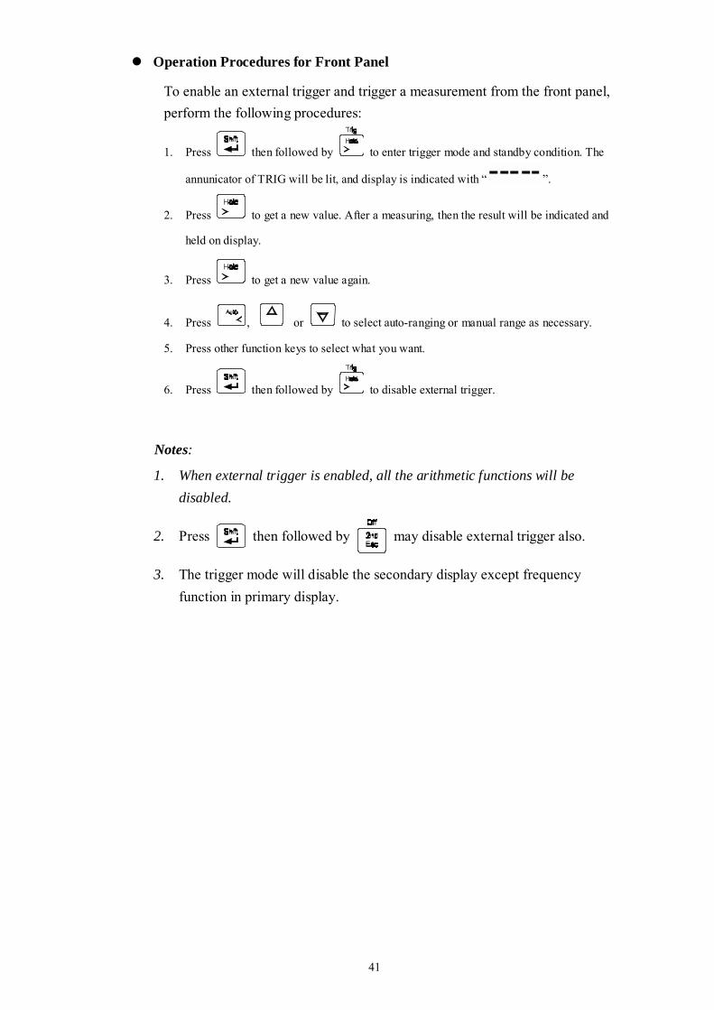
Operation Procedures for Front Panel
To enable an external trigger and trigger a measurement from the front panel, perform the following procedures:
1. Press then followed by to enter trigger mode and standby condition. The
annunicator of TRIG will be lit, and display is indicated with “ ”.
2. Press to get a new value. After a measuring, then the result will be indicated and
held on display.
3. Press to get a new value again.
4. Press , or to select auto-ranging or manual range as necessary.
5. Press other function keys to select what you want.
6. Press then followed by to disable external trigger.
Notes:
1. When external trigger is enabled, all the arithmetic functions will be disabled.
2. Press then followed by may disable external trigger also.
3. The trigger mode will disable the secondary display except frequency function in primary display.

2
(This page is subject to be blank)
3
Section 4 Measurement Application Examples
4-1 Introduction Section 4 describes some advanced features and applications that help the user to operate the meter more effectively. The user must be familiar with the basic measurement operations described in Section 2 and Section 3 and has a basic understanding of electronics knowledge.
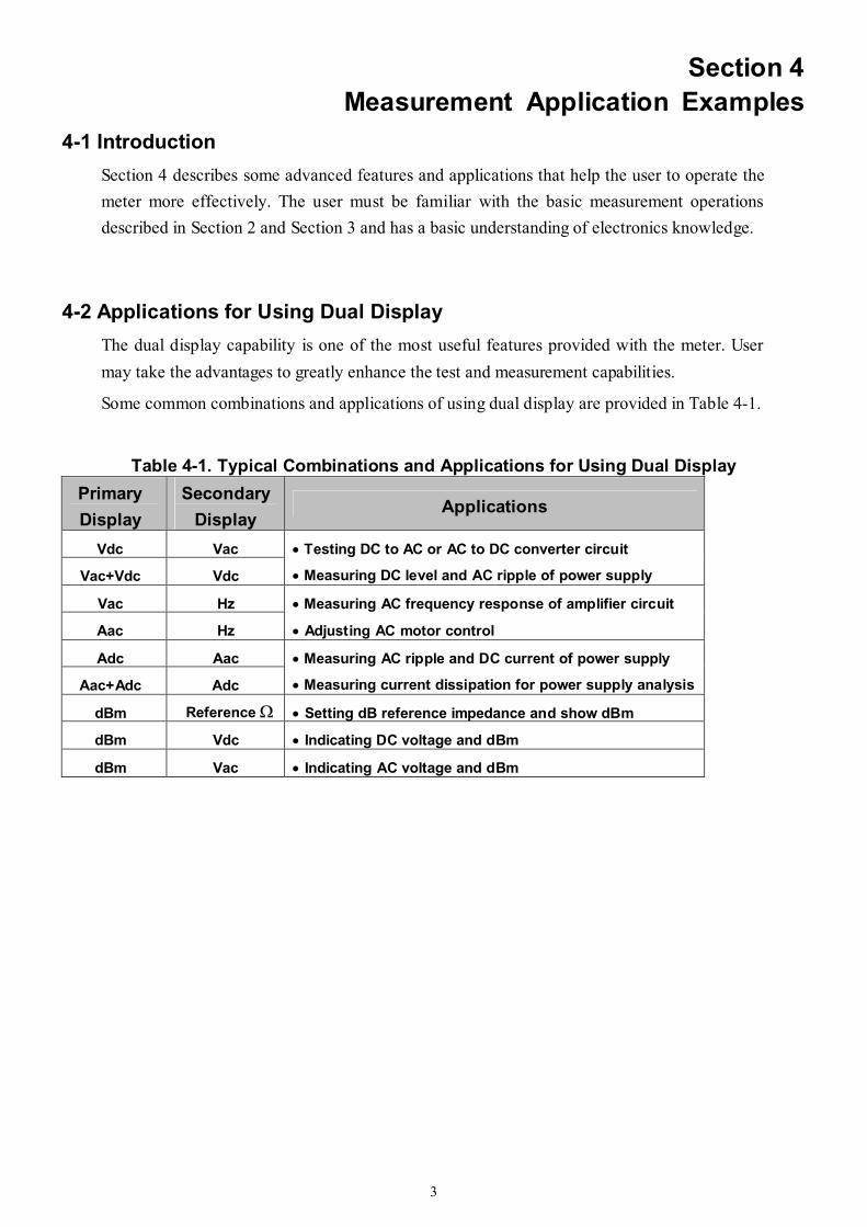
4-2 Applications for Using Dual Display The dual display capability is one of the most useful features provided with the meter. User may take the advantages to greatly enhance the test and measurement capabilities.
Some common combinations and applications of using dual display are provided in Table 4-1.
Table 4-1. Typical Combinations and Applications for Using Dual Display Primary Display
Secondary Display
Applications
Vdc Vac
Vac+Vdc Vdc
• Testing DC to AC or AC to DC converter circuit
• Measuring DC level and AC ripple of power supply
Vac Hz • Measuring AC frequency response of amplifier circuit
Aac Hz • Adjusting AC motor control
Adc Aac
Aac+Adc Adc
• Measuring AC ripple and DC current of power supply
• Measuring current dissipation for power supply analysis
dBm Reference Ω • Setting dB reference impedance and show dBm
dBm Vdc • Indicating DC voltage and dBm
dBm Vac • Indicating AC voltage and dBm
4
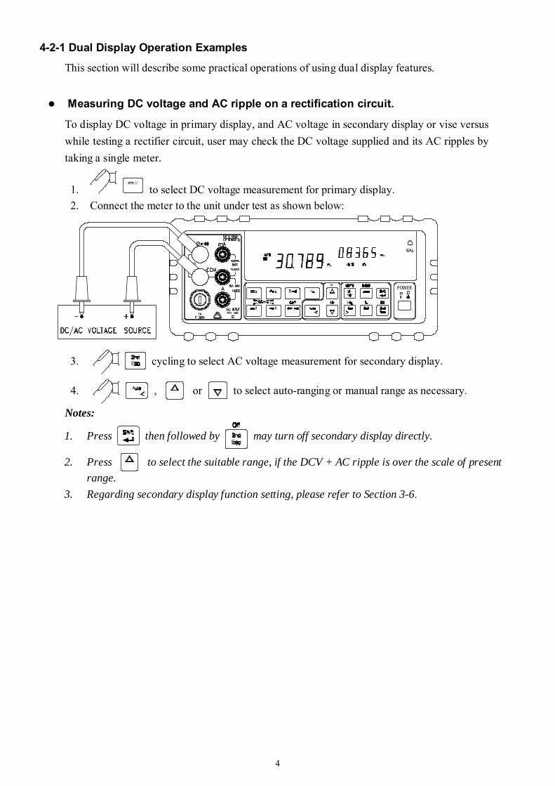
4-2-1 Dual Display Operation Examples This section will describe some practical operations of using dual display features.
Measuring DC voltage and AC ripple on a rectification circuit.
To display DC voltage in primary display, and AC voltage in secondary display or vise versus while testing a rectifier circuit, user may check the DC voltage supplied and its AC ripples by taking a single meter.
1. to select DC voltage measurement for primary display. 2. Connect the meter to the unit under test as shown below:
POWER
3. cycling to select AC voltage measurement for secondary display.
4. , or to select auto-ranging or manual range as necessary.
Notes:
1. Press then followed by may turn off secondary display directly.
2. Press to select the suitable range, if the DCV + AC ripple is over the scale of present range.
3. Regarding secondary display function setting, please refer to Section 3-6.
5
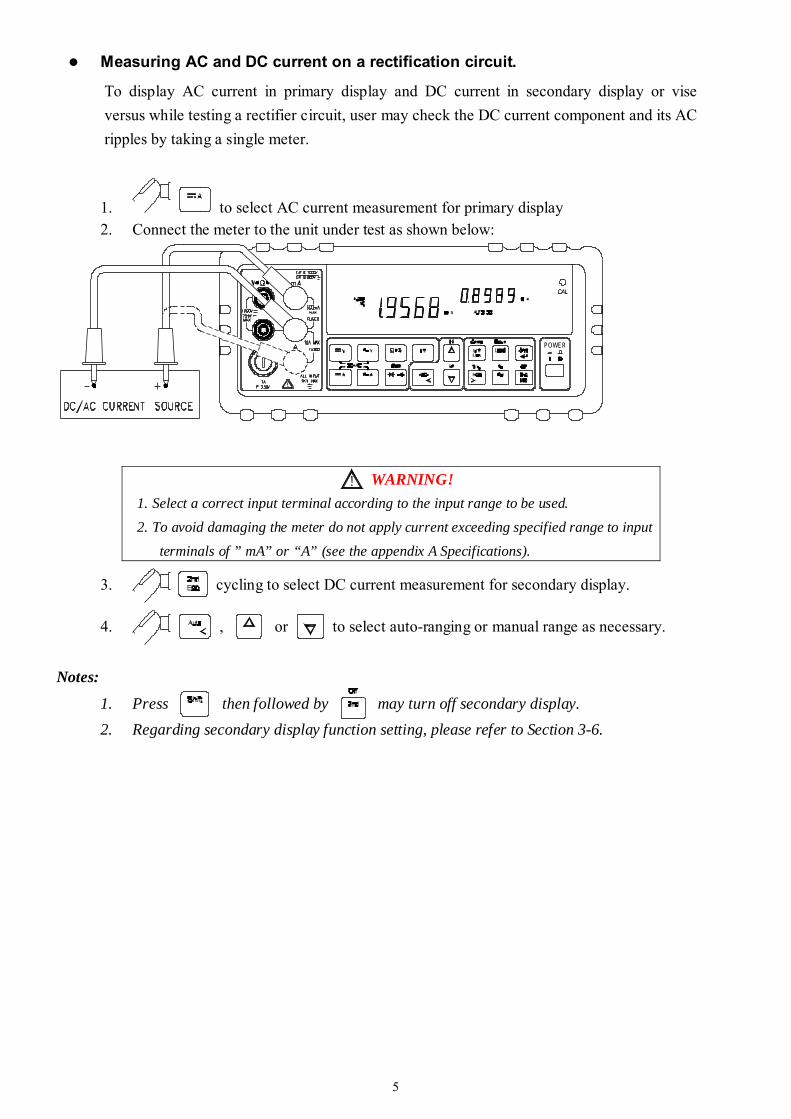
Measuring AC and DC current on a rectification circuit.
To display AC current in primary display and DC current in secondary display or vise versus while testing a rectifier circuit, user may check the DC current component and its AC ripples by taking a single meter.
1. to select AC current measurement for primary display 2. Connect the meter to the unit under test as shown below:
POWER
3. cycling to select DC current measurement for secondary display.
4. , or to select auto-ranging or manual range as necessary.
Notes:
1. Press then followed by may turn off secondary display. 2. Regarding secondary display function setting, please refer to Section 3-6.
WARNING! 1. Select a correct input terminal according to the input range to be used. 2. To avoid damaging the meter do not apply current exceeding specified range to input terminals of ” mA” or “A” (see the appendix A Specifications).
6
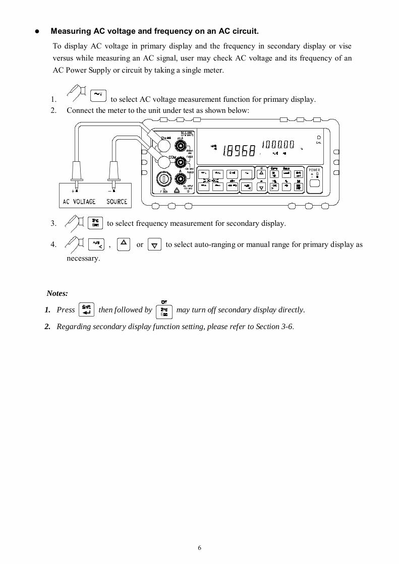
Measuring AC voltage and frequency on an AC circuit.
To display AC voltage in primary display and the frequency in secondary display or vise versus while measuring an AC signal, user may check AC voltage and its frequency of an AC Power Supply or circuit by taking a single meter.
1. to select AC voltage measurement function for primary display. 2. Connect the meter to the unit under test as shown below:
POWER
3. to select frequency measurement for secondary display.
4. , or to select auto-ranging or manual range for primary display as
necessary.
Notes:
1. Press then followed by may turn off secondary display directly.
2. Regarding secondary display function setting, please refer to Section 3-6.
7
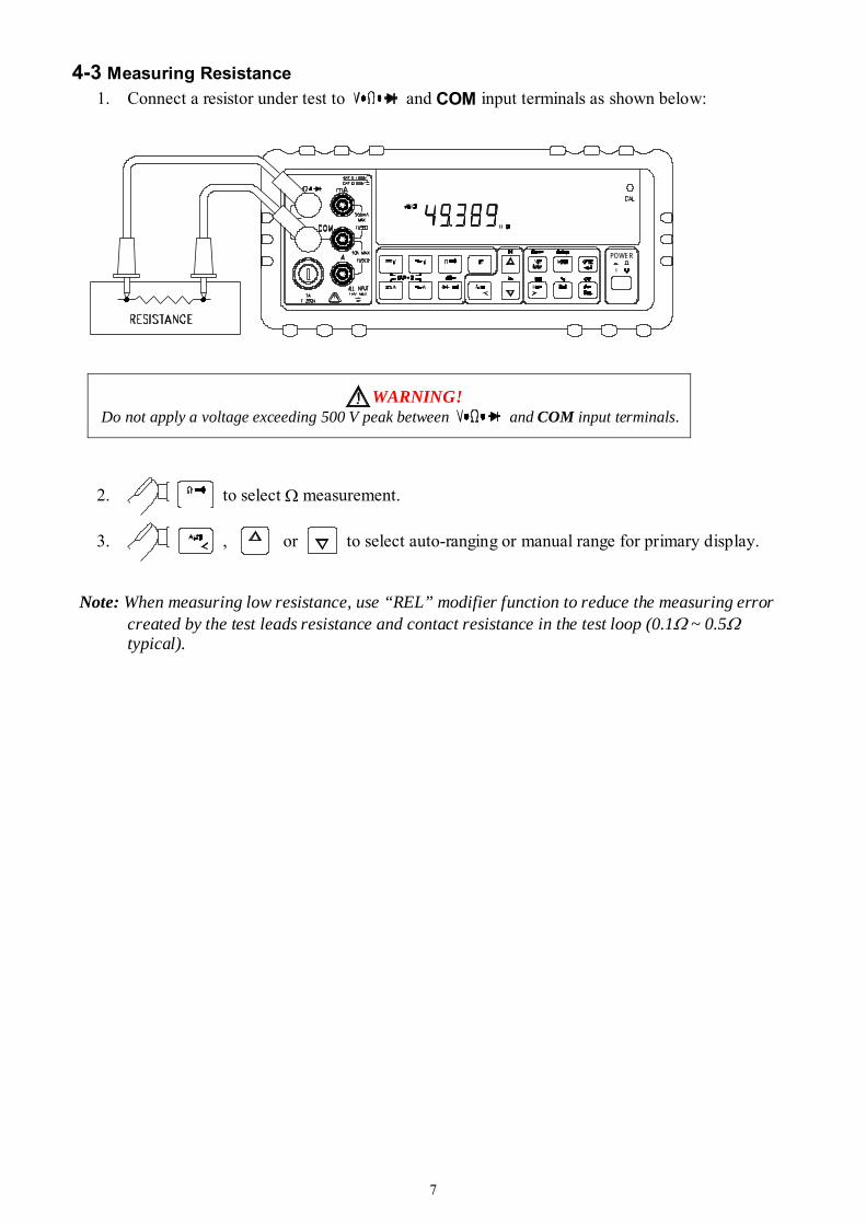
4-3 Measuring Resistance 1. Connect a resistor under test to and COM input terminals as shown below:
POWER
WARNING! Do not apply a voltage exceeding 500 V peak between and COM input terminals.
2. to select Ω measurement.
3. , or to select auto-ranging or manual range for primary display.
Note: When measuring low resistance, use “REL” modifier function to reduce the measuring error
created by the test leads resistance and contact resistance in the test loop (0.1Ω ~ 0.5Ω typical).
8
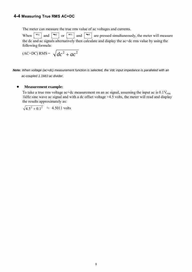
4-4 Measuring True RMS AC+DC
The meter can measure the true rms value of ac voltages and currents.
When and or and are pressed simultaneously, the meter will measure the dc and ac signals alternatively then calculate and display the ac+dc rms value by using the following formula:
(AC+DC) RMS = 22 acdc +
Note: When voltage (ac+dc) measurement function is selected, the Vdc input impedance is paralleled with an
ac-coupled 1.1MΩ ac divider.
Measurement example: To take a true rms voltage ac+dc measurement on an ac signal, assuming the input ac is 0.1Vrms 1kHz sine wave ac signal and with a dc offset voltage +4.5 volts, the meter will read and display the results approximately as:
22 1.05.4 + ≒ 4.5011 volts
9
Section 5 Calibrating the Meter
5-1 Introduction
CAUTION!
TO AVOID DAMAGING THE DEFAULT CALIBRATION DATA STORED IN A NON-VOLATILE
MEMORY, A CALIBRATION TO THE METER CAN ONLY BE DONE BY AN AUTHORIZED
SERVICE CENTER AND QUALIFIED PERSONNEL WITH APPROPRIATE EQUIPMENT.
THE WARRANTY WILL BE EXPIRED IF THE SEALED LABEL ON THE CAL BUTTON OF THE
FRONT PANEL IS BROKEN.
FORE DETAIL INFORMATION ABOUT CALIBRATION PROCEDURES, PLEASE CONTACT
FACTORY OR AUTHORIZED DISTRIBUTOR.
It is recommended to recalibrate and verify the meter at least once a year to ensure it meets the original designed performance and specifications. The meter is designed with closed-case calibration capability (no internal adjustment). To enter calibration mode by pressing the CAL button located in the hole on the upper right position of the front panel display screen. The meter can be calibrated and verified by keystrokes via the front panel or through RS-232 interface command with appropriate equipment and qualified personnel only.
5-2 Environmental Condition Calibration or verification test should be performed under laboratory condition which ambient temperature/ relative humidity can be controlled.
5-3 Warm up Allow up to at least 60 minutes warm-up time before performing calibration or a verification test to the meter. After exposure or storage in a high humidity (condensing) environment, 2 hours warm-up time is essentially required.

10
5-4 Recommended Test Equipment The test equipment requirements listed in Table 5-1 or equivalents are required to perform the calibration and performance verification test procedures. Alternative equipment may be used as long as the accuracy is at least as good as those listed.
Table 5-1 Standard Equipment Requirements
Standard Source
Operating Range
Accuracy Required
Recommended Equipment
DC Voltage Calibrator Range, 0 to 1000VDC ≤ ± 0.002%
Fluke 5520A or equivalent
AC Voltage Calibrator
Range, 0 to 750V, 1kHz ≤ ± 0.03% Fluke 5520A or equivalent
10mA to 100mA ≤ ± 0.01% DC Current Calibrator 1A to 10A ≤ ± 0.03%
Fluke 5520A or equivalent
10mA to 1000mA, 1kHz ≤ ± 0.1% AC Current Calibrator 1A to 10A, 1kHz ≤ ± 0.2 %
Fluke5520A or equivalent
450Ω, 4.5kΩ, 45kΩ, 450kΩ, 4.5MΩ
≤ ± 0.01% Fluke 5520A or equivalent Resistance
Calibrator 30MΩ ≤ ± 0.05%
Fluke 5520A or equivalent
Audio Level Generator
2V/4500Hz ≤ ± 0.005% Fluke 5520A or equivalent
Section 6 RS-232 Remote Operation
6-1 Introduction
Section 6 describes how to operate the meter via standard RS-232 interface. It also explains the detail information of all RS-232 interface command sets used in the meter. The remote control operation enables the user either to manually operate the meter via a terminal or executes a host computer program automatically.
6-2 RS-232 Interface Overview
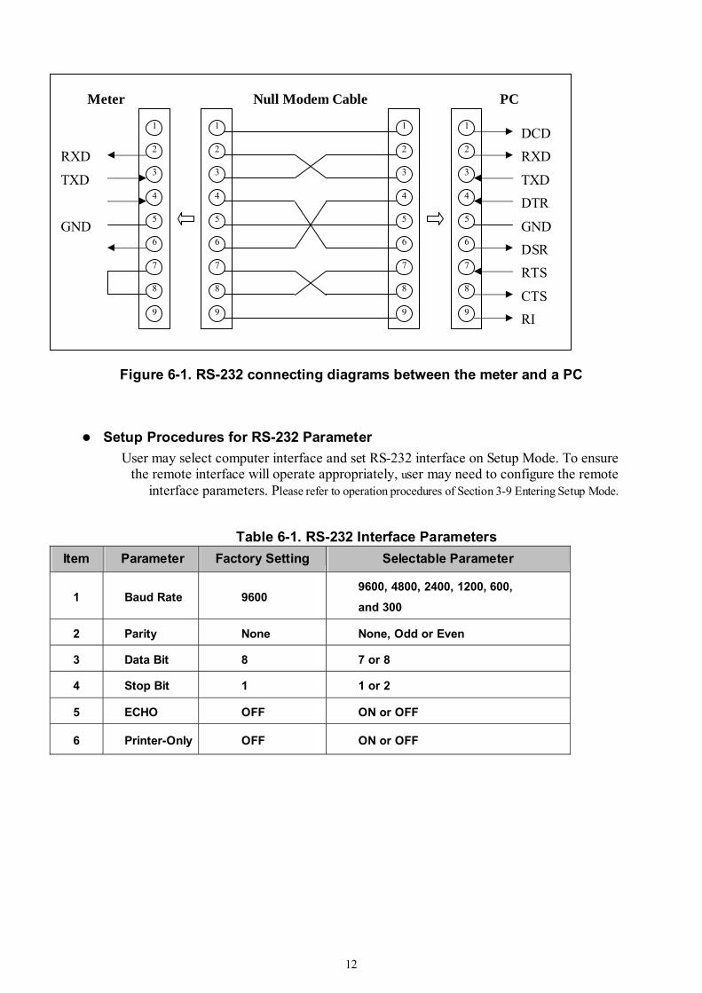
The port serial contains of D-type 9-pin male connector on rear panel of the meter is used to communicate the meter with a host computer, or terminal via RS-232 standard interface. Figure 6-1 shows the RS-232 connecting diagram between the meter and a host computer.
RS-232 interface is a serial binary data interchange, which operates from 300 to 9600 baud rate, and the distance between any two RS-232 interfaces can be extended up to 50 feet. RS-232 port of the meter is designed in full duplex, which makes the meter more reliable and efficient in data taking.

11
6-3 RS-232 Interface Parameters Set up
In order to operate the meter via a host computer or terminal, the parameters in RS-232 interface within the meter has to match the parameters in the serial interface provided by the host or terminal.
The following procedures will guide the user to set up RS-232 interface parameters within the meter to comply RS-232 interface with the host. The default settings of the meter at factory are 9600-baud rate, non-parity, 8 data bits, and 1 stop bit (9600, n, 8, 1).
Table 6-1 indicates the factory settings and user selectable communication parameters by using RS-232 interface.
12
Figure 6-1. RS-232 connecting diagrams between the meter and a PC
Setup Procedures for RS-232 Parameter User may select computer interface and set RS-232 interface on Setup Mode. To ensure
the remote interface will operate appropriately, user may need to configure the remote interface parameters. Please refer to operation procedures of Section 3-9 Entering Setup Mode.
Table 6-1. RS-232 Interface Parameters Item Parameter Factory Setting Selectable Parameter
1 Baud Rate 9600 9600, 4800, 2400, 1200, 600,
and 300
2 Parity None None, Odd or Even
3 Data Bit 8 7 or 8
4 Stop Bit 1 1 or 2
5 ECHO OFF ON or OFF
6 Printer-Only OFF ON or OFF
1
2
3
4
5
6
7
8
9
1
2
3
4
5
6
7
8
9
1
2
3
4
5
6
7
8
9
1
2
3
4
5
6
7
8
9
DCD RXD
TXD DTR
GND DSR RTS
CTS RI
RXD
TXD
GND
Null Modem Cable Meter PC
13
6-4 Using Commands
Note: All RS-232 commands must be entered in the upper case.
6-4-1 Types of Commands
The RS-232 commands are grouped in three types:
KEY commands, SET commands, and QUERY commands.
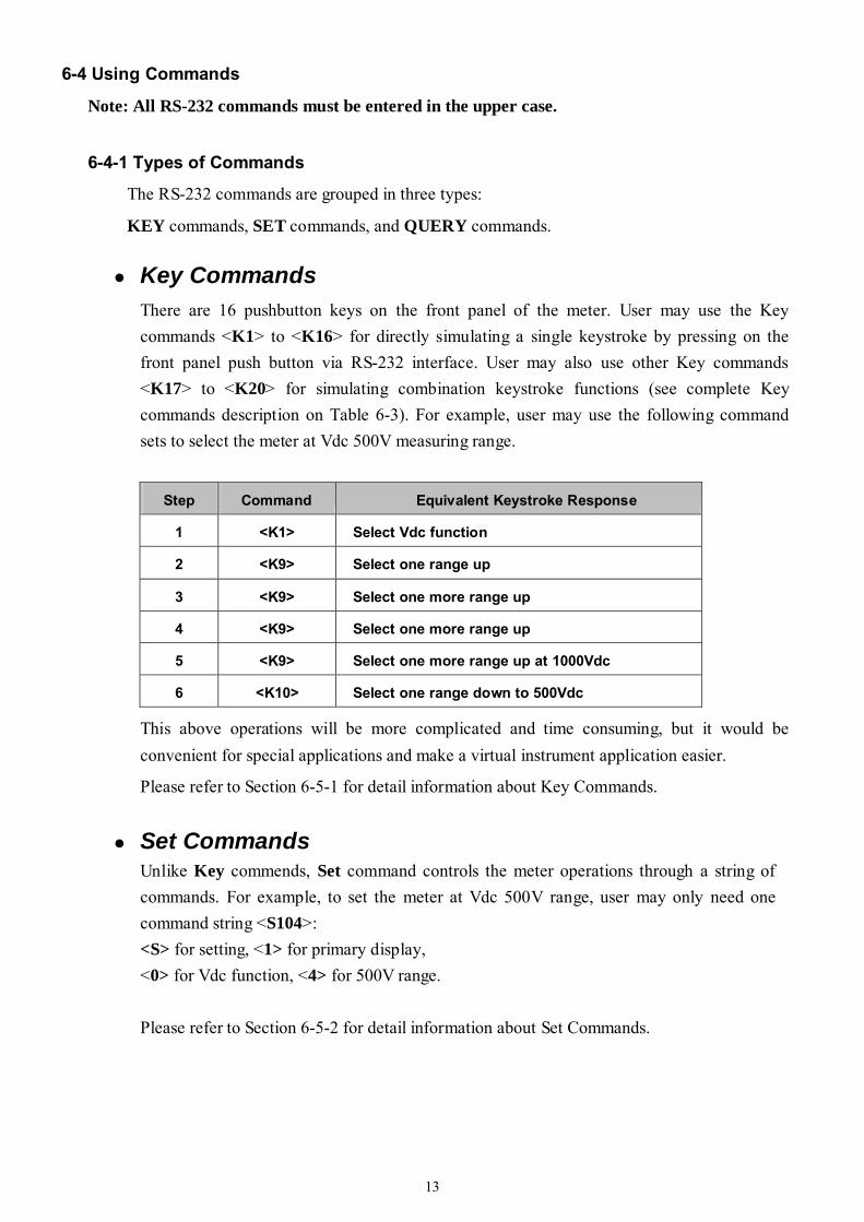
Key Commands There are 16 pushbutton keys on the front panel of the meter. User may use the Key commands <K1> to <K16> for directly simulating a single keystroke by pressing on the front panel push button via RS-232 interface. User may also use other Key commands <K17> to <K20> for simulating combination keystroke functions (see complete Key commands description on Table 6-3). For example, user may use the following command sets to select the meter at Vdc 500V measuring range.
Step Command Equivalent Keystroke Response
1 <K1> Select Vdc function
2 <K9> Select one range up
3 <K9> Select one more range up
4 <K9> Select one more range up
5 <K9> Select one more range up at 1000Vdc
6 <K10> Select one range down to 500Vdc
This above operations will be more complicated and time consuming, but it would be convenient for special applications and make a virtual instrument application easier.
Please refer to Section 6-5-1 for detail information about Key Commands.
Set Commands
Unlike Key commends, Set command controls the meter operations through a string of commands. For example, to set the meter at Vdc 500V range, user may only need one command string <S104>: <S> for setting, <1> for primary display, <0> for Vdc function, <4> for 500V range. Please refer to Section 6-5-2 for detail information about Set Commands.
14
Query Commands The purpose of Query commands is used for requesting the meter to respond its current status. An example of a query command <R1> is used for requesting the meter to respond its primary display characters. Please refer to Section 6-5-3 for detail information about Query Commands.
6-4-2 Command Syntax Echo
With echo ON, the meter echoes (returns) all the characters whatever it receives.
Terminator A terminator is a character sent by a host, which identifies the end of a command string. A valid terminator consists of two-byte data: <CR> (Carriage Return) and <LF> (Line Feed)
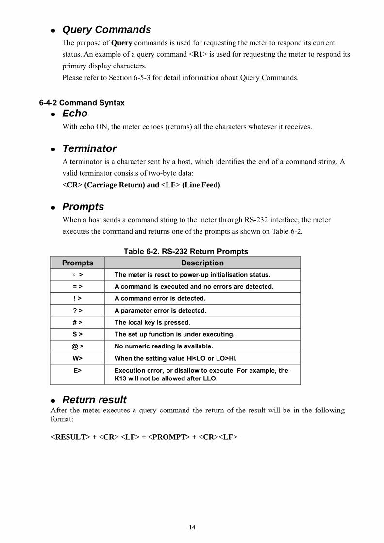
Prompts When a host sends a command string to the meter through RS-232 interface, the meter executes the command and returns one of the prompts as shown on Table 6-2.
Table 6-2. RS-232 Return Prompts Prompts Description
﹡> The meter is reset to power-up initialisation status.
= > A command is executed and no errors are detected.
! > A command error is detected.
? > A parameter error is detected.
# > The local key is pressed.
S > The set up function is under executing.
@ > No numeric reading is available.
W> When the setting value HI<LO or LO>HI.
E> Execution error, or disallow to execute. For example, the K13 will not be allowed after LLO.
Return result
After the meter executes a query command the return of the result will be in the following format: <RESULT> + <CR> <LF> + <PROMPT> + <CR><LF>
15
If RS-232 of the meter is under print-only mode, the meter will print out the measured data when the measurement cycle is completed. The format of printed data will be shown as one of the following: 1. <Measurement Data> + <CR> <LF>
for only primary display mode is enabled, or 2. <Measurement Data #1>, <Measurement Data #2> + <CR> <LF>
for both primary display and secondary display mode are enabled
6-5 Instructions of Command Sets
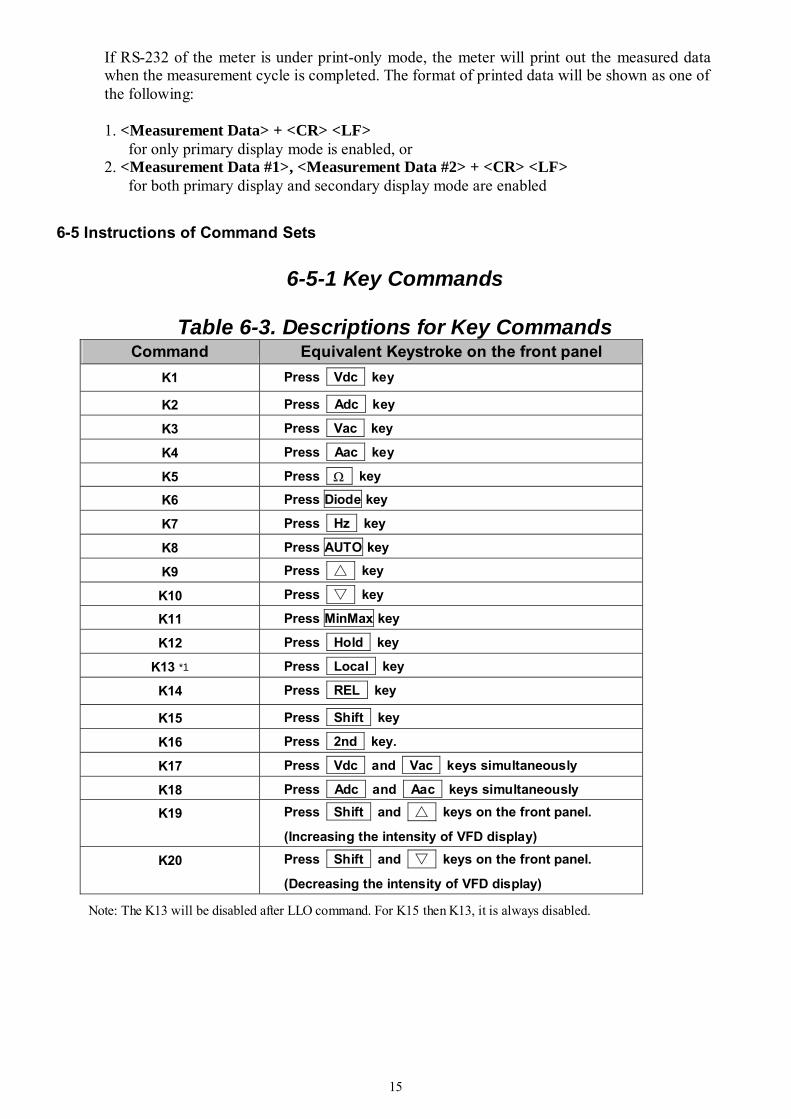
6-5-1 Key Commands
Table 6-3. Descriptions for Key Commands Command Equivalent Keystroke on the front panel
K1 Press Vdc key
K2 Press Adc key
K3 Press Vac key
K4 Press Aac key
K5 Press Ω key
K6 Press Diode key
K7 Press Hz key
K8 Press AUTO key
K9 Press key
K10 Press key
K11 Press MinMax key
K12 Press Hold key
K13 *1 Press Local key
K14 Press REL key
K15 Press Shift key
K16 Press 2nd key.
K17 Press Vdc and Vac keys simultaneously
K18 Press Adc and Aac keys simultaneously
K19 Press Shift and keys on the front panel.
(Increasing the intensity of VFD display)
K20 Press Shift and keys on the front panel.
(Decreasing the intensity of VFD display)
Note: The K13 will be disabled after LLO command. For K15 then K13, it is always disabled.
16
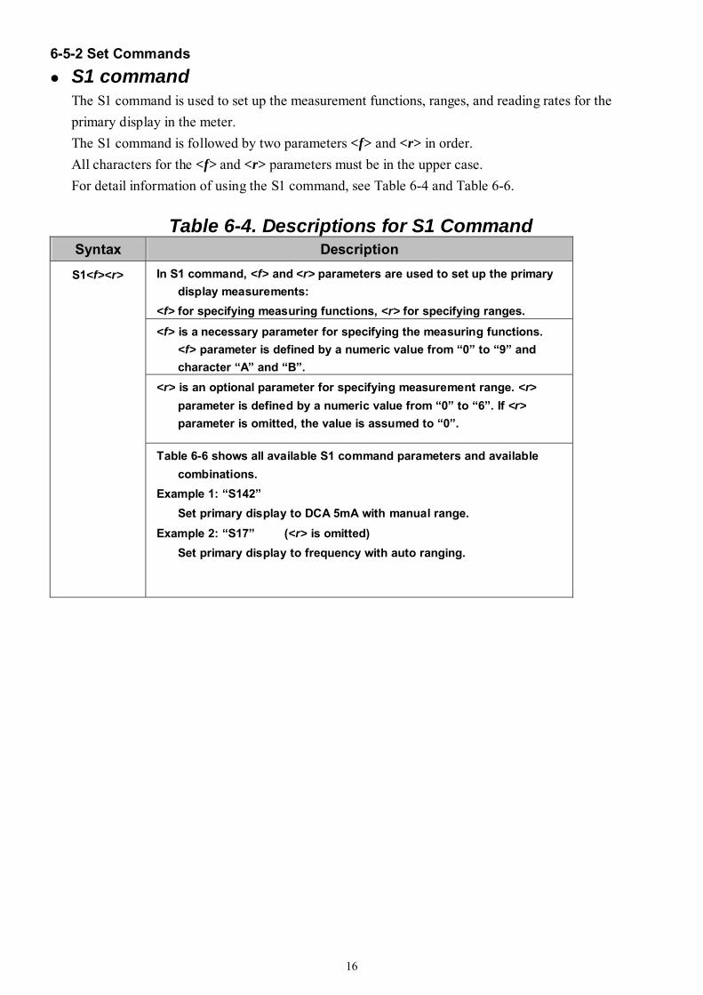
6-5-2 Set Commands S1 command
The S1 command is used to set up the measurement functions, ranges, and reading rates for the primary display in the meter. The S1 command is followed by two parameters <f> and <r> in order. All characters for the <f> and <r> parameters must be in the upper case. For detail information of using the S1 command, see Table 6-4 and Table 6-6.
Table 6-4. Descriptions for S1 Command Syntax Description
In S1 command, <f> and <r> parameters are used to set up the primary display measurements:
<f> for specifying measuring functions, <r> for specifying ranges.
<f> is a necessary parameter for specifying the measuring functions. <f> parameter is defined by a numeric value from “0” to “9” and character “A” and “B”.
<r> is an optional parameter for specifying measurement range. <r> parameter is defined by a numeric value from “0” to “6”. If <r> parameter is omitted, the value is assumed to “0”.
S1<f><r>
Table 6-6 shows all available S1 command parameters and available combinations.
Example 1: “S142” Set primary display to DCA 5mA with manual range.
Example 2: “S17” (<r> is omitted) Set primary display to frequency with auto ranging.

17
Table 6-5. Descriptions for S2 Command Command Description
In S2 command, <f> parameters is used to set up the secondary display measurements:
<f> for specifying measuring functions with auto-ranging. <r> It is used only to select sensitivity range for AC voltage or current
measurement once the primary display is frequency measurement. If the primary display is DCV, ACV, DCA or ACA, the command for secondary display should be <0> or skip <r>. Otherwise, the secondary display will be set to auto-ranging mode and return “?>”.
<f> is a necessary parameter for specifying the measuring functions. <f> parameter is defined by a numeric value from “0” to “9” and character “A” and “B”.
Because the secondary display can only display DCV, ACV, DCA, ACA, dBm and Frequency (Hz) functions, therefore, the available parameters are “0”, “1”, “4”, “5”, “7” and “B”.
S2<f><r>
Table 6-6 shows all available S2 command parameters and available combinations.
Example 1: “S24” Set secondary display to DCA.
Example 2: “S212” 1. Set secondary display to ACV 5V, if primary display is Hz
measurement.
18
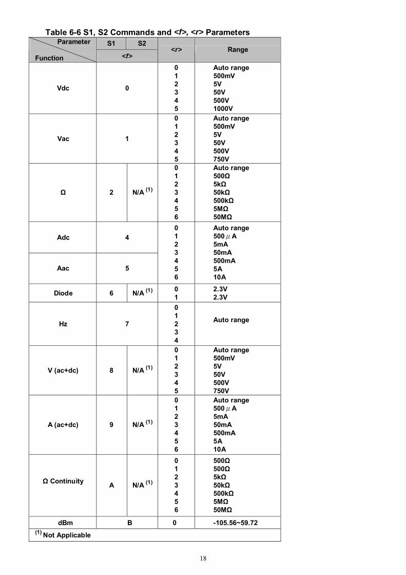
Table 6-6 S1, S2 Commands and <f>, <r> Parameters S1 S2 Parameter
Function <f>
<r> Range
Vdc 0
0 1 2 3 4 5
Auto range 500mV 5V 50V 500V 1000V
Vac 1
0 1 2 3 4 5
Auto range 500mV 5V 50V 500V 750V
Ω 2 N/A (1)
0 1 2 3 4 5 6
Auto range 500Ω 5kΩ 50kΩ 500kΩ 5MΩ 50MΩ
Adc 4
Aac 5
0 1 2 3 4 5 6
Auto range 500μA 5mA 50mA 500mA 5A 10A
Diode 6 N/A (1) 0 1
2.3V 2.3V
Hz 7
0 1 2 3 4
Auto range
V (ac+dc) 8 N/A (1)
0 1 2 3 4 5
Auto range 500mV 5V 50V 500V 750V
A (ac+dc) 9 N/A (1)
0 1 2 3 4 5 6
Auto range 500μA 5mA 50mA 500mA 5A 10A
Ω Continuity A N/A (1)
0 1 2 3 4 5 6
500Ω 500Ω 5kΩ 50kΩ 500kΩ 5MΩ 50MΩ
dBm B 0 -105.56~59.72 (1) Not Applicable
19
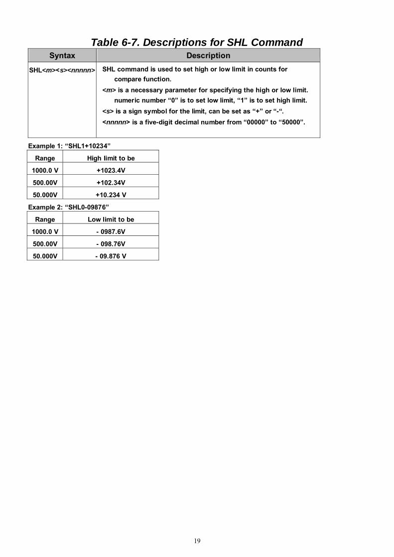
Table 6-7. Descriptions for SHL Command
Syntax Description
SHL<m><s><nnnnn> SHL command is used to set high or low limit in counts for compare function.
<m> is a necessary parameter for specifying the high or low limit. numeric number “0” is to set low limit, “1” is to set high limit.
<s> is a sign symbol for the limit, can be set as “+” or “-“. <nnnnn> is a five-digit decimal number from “00000” to “50000”.
Example 1: “SHL1+10234” Range High limit to be
1000.0 V +1023.4V
500.00V +102.34V
50.000V +10.234 V
Example 2: “SHL0-09876” Range Low limit to be
1000.0 V - 0987.6V
500.00V - 098.76V
50.000V - 09.876 V
20
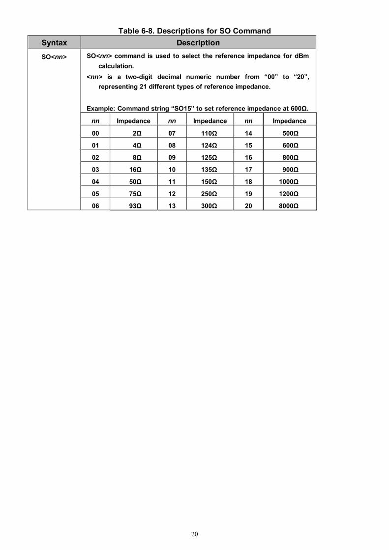
Table 6-8. Descriptions for SO Command Syntax Description
SO<nn> command is used to select the reference impedance for dBm calculation.
<nn> is a two-digit decimal numeric number from “00” to “20”, representing 21 different types of reference impedance.
Example: Command string “SO15” to set reference impedance at 600Ω.
nn Impedance nn Impedance nn Impedance 00 2Ω 07 110Ω 14 500Ω 01 4Ω 08 124Ω 15 600Ω 02 8Ω 09 125Ω 16 800Ω 03 16Ω 10 135Ω 17 900Ω 04 50Ω 11 150Ω 18 1000Ω 05 75Ω 12 250Ω 19 1200Ω
SO<nn>
06 93Ω 13 300Ω 20 8000Ω
21
6-5-3 Query Commands
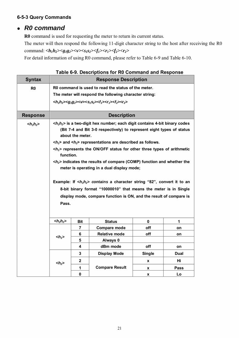
R0 command R0 command is used for requesting the meter to return its current status. The meter will then respond the following 11-digit character string to the host after receiving the R0 command: <h1h2><g1g2><v><s1s2><f1><r1><f2><r2> For detail information of using R0 command, please refer to Table 6-9 and Table 6-10.
Table 6-9. Descriptions for R0 Command and Response
Syntax Response Description
R0 R0 command is used to read the status of the meter. The meter will respond the following character string:
<h1h2><g1g2><v><s1s2><f1><r1><f2><r2>
Response Description <h1h2> is a two-digit hex number; each digit contains 4-bit binary codes
(Bit 7-4 and Bit 3-0 respectively) to represent eight types of status about the meter.
<h1> and <h2> representations are described as follows. <h1> represents the ON/OFF status for other three types of arithmetic
function. <h2> indicates the results of compare (COMP) function and whether the
meter is operating in a dual display mode;
Example: If <h1h2> contains a character string “82”, convert it to an
8-bit binary format “10000010” that means the meter is in Single
display mode, compare function is ON, and the result of compare is
Pass.
<h1h2> Bit Status 0 1 7 Compare mode off on 6 Relative mode off on 5 Always 0
<h1>
4 dBm mode off on
3 Display Mode Single Dual
2 x Hi
1 x Pass
<h1h2>
<h2>
0 Compare Result
x Lo
22
Table 6-9. Descriptions for R0 Command and Response (cont’d) Response Description
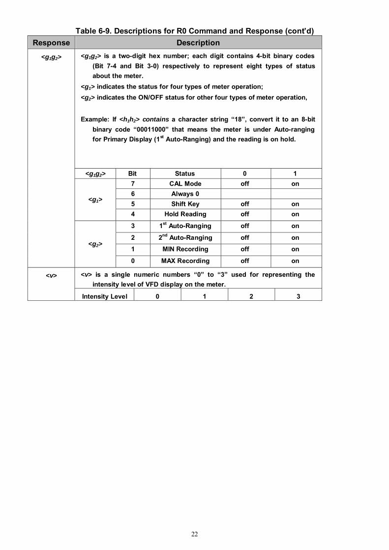
<g1g2> is a two-digit hex number; each digit contains 4-bit binary codes (Bit 7-4 and Bit 3-0) respectively to represent eight types of status about the meter.
<g1> indicates the status for four types of meter operation; <g2> indicates the ON/OFF status for other four types of meter operation, Example: If <h1h2> contains a character string “18”, convert it to an 8-bit
binary code “00011000” that means the meter is under Auto-ranging for Primary Display (1st Auto-Ranging) and the reading is on hold.
<g1g2> Bit Status 0 1 7 CAL Mode off on 6 Always 0 5 Shift Key off on
<g1>
4 Hold Reading off on
3 1st Auto-Ranging off on
2 2nd Auto-Ranging off on
1 MIN Recording off on
<g1g2>
<g2>
0 MAX Recording off on
<v> is a single numeric numbers “0” to “3” used for representing the intensity level of VFD display on the meter.
<v>
Intensity Level 0 1 2 3
23
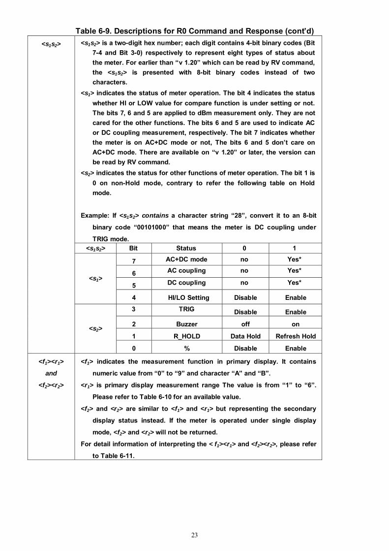
Table 6-9. Descriptions for R0 Command and Response (cont’d) <s1s2> is a two-digit hex number; each digit contains 4-bit binary codes (Bit
7-4 and Bit 3-0) respectively to represent eight types of status about the meter. For earlier than “v 1.20” which can be read by RV command, the <s1s2> is presented with 8-bit binary codes instead of two characters.
<s1> indicates the status of meter operation. The bit 4 indicates the status whether HI or LOW value for compare function is under setting or not. The bits 7, 6 and 5 are applied to dBm measurement only. They are not cared for the other functions. The bits 6 and 5 are used to indicate AC or DC coupling measurement, respectively. The bit 7 indicates whether the meter is on AC+DC mode or not, The bits 6 and 5 don’t care on AC+DC mode. There are available on “v 1.20” or later, the version can be read by RV command.
<s2> indicates the status for other functions of meter operation. The bit 1 is 0 on non-Hold mode, contrary to refer the following table on Hold mode.
Example: If <s1s2> contains a character string “28”, convert it to an 8-bit
binary code “00101000” that means the meter is DC coupling under
TRIG mode. <s1s2> Bit Status 0 1
7 AC+DC mode no Yes*
6 AC coupling no Yes*
5 DC coupling no Yes* <s1>
4 HI/LO Setting Disable Enable
3 TRIG Disable Enable
2 Buzzer off on
1 R_HOLD Data Hold Refresh Hold
<s1s2>
<s2>
0 % Disable Enable
<f1><r1>
and
<f2><r2>
<f1> indicates the measurement function in primary display. It contains
numeric value from “0” to “9” and character “A” and “B”.
<r1> is primary display measurement range The value is from “1” to “6”.
Please refer to Table 6-10 for an available value.
<f2> and <r2> are similar to <f1> and <r1> but representing the secondary
display status instead. If the meter is operated under single display
mode, <f2> and <r2> will not be returned.
For detail information of interpreting the < f1><r1> and <f2><r2>, please refer
to Table 6-11.
24
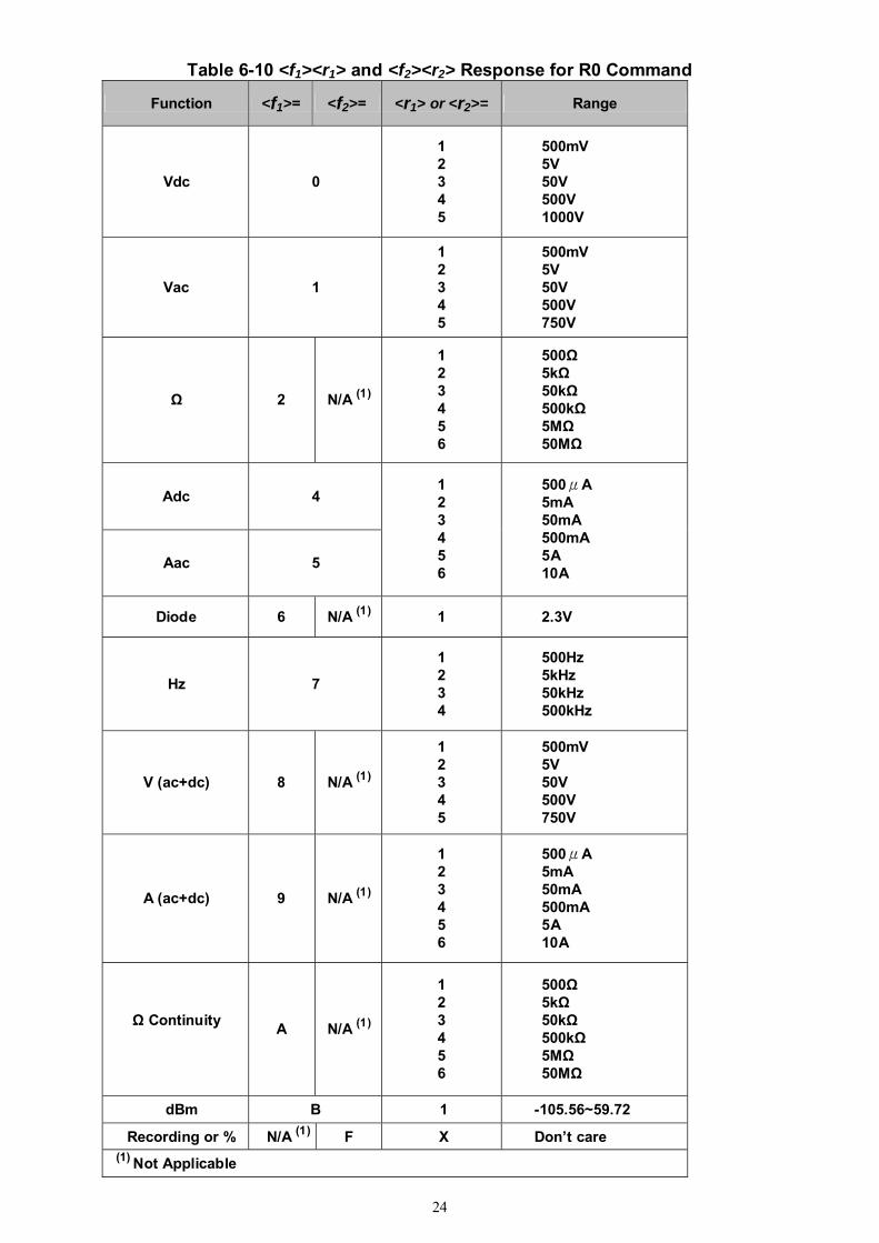
Table 6-10 <f1><r1> and <f2><r2> Response for R0 Command
Function <f1>= <f2>= <r1> or <r2>= Range
Vdc 0
1 2 3 4 5
500mV 5V 50V 500V 1000V
Vac 1
1 2 3 4 5
500mV 5V 50V 500V 750V
Ω 2 N/A (1)
1 2 3 4 5 6
500Ω 5kΩ 50kΩ 500kΩ 5MΩ 50MΩ
Adc 4
Aac 5
1 2 3 4 5 6
500μA 5mA 50mA 500mA 5A 10A
Diode 6 N/A (1) 1 2.3V
Hz 7
1 2 3 4
500Hz 5kHz 50kHz 500kHz
V (ac+dc) 8 N/A (1)
1 2 3 4 5
500mV 5V 50V 500V 750V
A (ac+dc) 9 N/A (1)
1 2 3 4 5 6
500μA 5mA 50mA 500mA 5A 10A
Ω Continuity A N/A (1)
1 2 3 4 5 6
500Ω 5kΩ 50kΩ 500kΩ 5MΩ 50MΩ
dBm B 1 -105.56~59.72
Recording or % N/A (1) F X Don’t care (1) Not Applicable
25
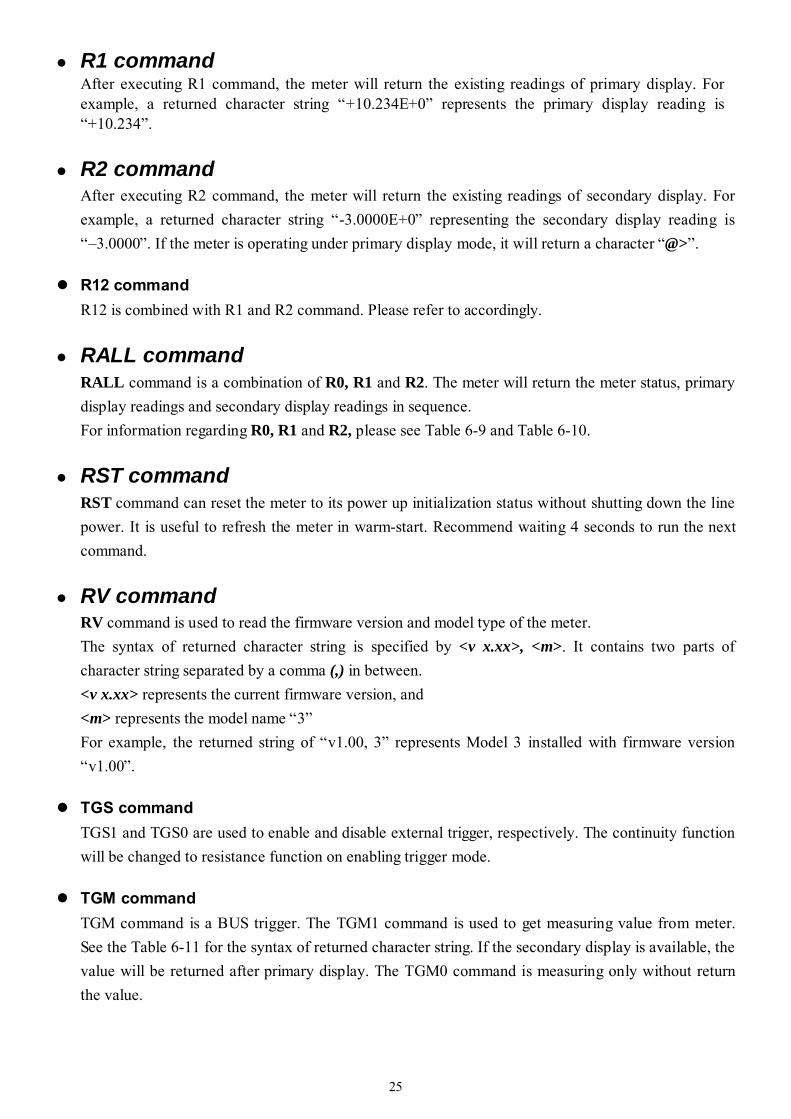
R1 command After executing R1 command, the meter will return the existing readings of primary display. For example, a returned character string “+10.234E+0” represents the primary display reading is “+10.234”.
R2 command After executing R2 command, the meter will return the existing readings of secondary display. For example, a returned character string “-3.0000E+0” representing the secondary display reading is “–3.0000”. If the meter is operating under primary display mode, it will return a character “@>”.
R12 command R12 is combined with R1 and R2 command. Please refer to accordingly.
RALL command RALL command is a combination of R0, R1 and R2. The meter will return the meter status, primary display readings and secondary display readings in sequence. For information regarding R0, R1 and R2, please see Table 6-9 and Table 6-10.
RST command RST command can reset the meter to its power up initialization status without shutting down the line power. It is useful to refresh the meter in warm-start. Recommend waiting 4 seconds to run the next command.
RV command RV command is used to read the firmware version and model type of the meter. The syntax of returned character string is specified by <v x.xx>, <m>. It contains two parts of character string separated by a comma (,) in between. <v x.xx> represents the current firmware version, and <m> represents the model name “3” For example, the returned string of “v1.00, 3” represents Model 3 installed with firmware version “v1.00”.
TGS command TGS1 and TGS0 are used to enable and disable external trigger, respectively. The continuity function will be changed to resistance function on enabling trigger mode.
TGM command TGM command is a BUS trigger. The TGM1 command is used to get measuring value from meter. See the Table 6-11 for the syntax of returned character string. If the secondary display is available, the value will be returned after primary display. The TGM0 command is measuring only without return the value.

26
Table 6-11. The syntax of returned character string Function Range Return Value
500mV ±500.00E-3 5V ±5.0000E+0 50V ±50.000E+0 500V ±500.00E+0
DC Voltage
1000V ±1000.0E+0 500mV +500.00E-3
5V +5.0000E+0 50V +50.000E+0 500V +500.00E+0
AC / AC+DC Voltage
750V +0750.0E+0 500μA ±500.00E-6
5mA ±5.0000E-3 50mA ±50.000E-3 500mA ±500.00E-3
5A ±5.0000E+0
DC / AC / AC+DC Current
10A ±10.000E+0 500Ω +500.00E+0 5KΩ +5.0000E+3 50KΩ +50.000E+3 500KΩ +500.00E+3 5MΩ +5.0000E+6
Resistance
50MΩ +50.000E+6 500Hz +500.00E+0 5KHz +5.0000E+3 50KHz +50.000E+3
Frequency
500KHz +500.00E+3 Note: The return string of ±9E+9 means overload condition.
LLO command
LLO command is used to lock local key operation. The K13 will not been used after this command.
GTL command GTL command is used to exit remote state and go to local. The K13 will be available then.
BON command BON command is caused the meter to sound one tone.
27
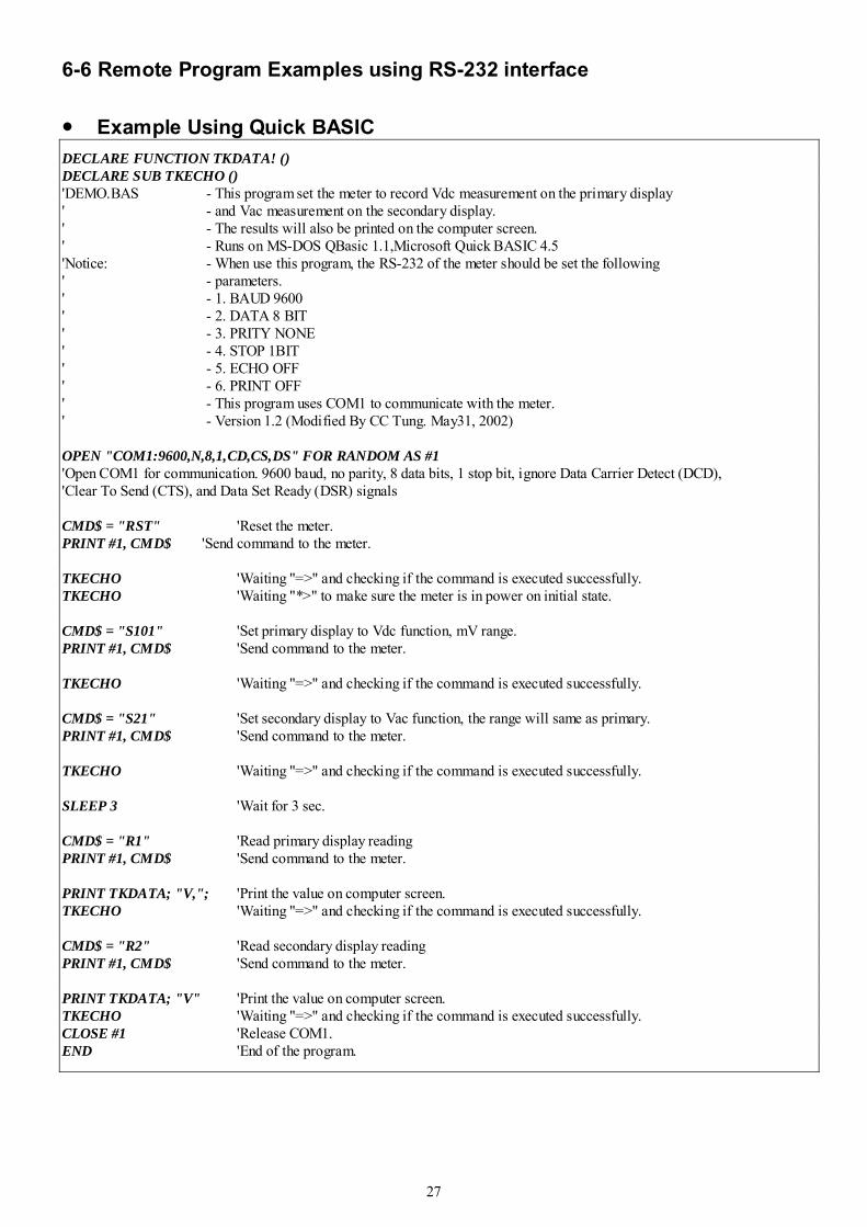
6-6 Remote Program Examples using RS-232 interface
Example Using Quick BASIC DECLARE FUNCTION TKDATA! () DECLARE SUB TKECHO () 'DEMO.BAS - This program set the meter to record Vdc measurement on the primary display ' - and Vac measurement on the secondary display. ' - The results will also be printed on the computer screen. ' - Runs on MS-DOS QBasic 1.1,Microsoft Quick BASIC 4.5 'Notice: - When use this program, the RS-232 of the meter should be set the following ' - parameters. ' - 1. BAUD 9600 ' - 2. DATA 8 BIT ' - 3. PRITY NONE ' - 4. STOP 1BIT ' - 5. ECHO OFF ' - 6. PRINT OFF ' - This program uses COM1 to communicate with the meter. ' - Version 1.2 (Modified By CC Tung. May31, 2002) OPEN "COM1:9600,N,8,1,CD,CS,DS" FOR RANDOM AS #1 'Open COM1 for communication. 9600 baud, no parity, 8 data bits, 1 stop bit, ignore Data Carrier Detect (DCD), 'Clear To Send (CTS), and Data Set Ready (DSR) signals CMD$ = "RST" 'Reset the meter. PRINT #1, CMD$ 'Send command to the meter. TKECHO 'Waiting "=>" and checking if the command is executed successfully. TKECHO 'Waiting "*>" to make sure the meter is in power on initial state. CMD$ = "S101" 'Set primary display to Vdc function, mV range. PRINT #1, CMD$ 'Send command to the meter. TKECHO 'Waiting "=>" and checking if the command is executed successfully. CMD$ = "S21" 'Set secondary display to Vac function, the range will same as primary. PRINT #1, CMD$ 'Send command to the meter. TKECHO 'Waiting "=>" and checking if the command is executed successfully. SLEEP 3 'Wait for 3 sec. CMD$ = "R1" 'Read primary display reading PRINT #1, CMD$ 'Send command to the meter. PRINT TKDATA; "V,"; 'Print the value on computer screen. TKECHO 'Waiting "=>" and checking if the command is executed successfully. CMD$ = "R2" 'Read secondary display reading PRINT #1, CMD$ 'Send command to the meter. PRINT TKDATA; "V" 'Print the value on computer screen. TKECHO 'Waiting "=>" and checking if the command is executed successfully. CLOSE #1 'Release COM1. END 'End of the program.
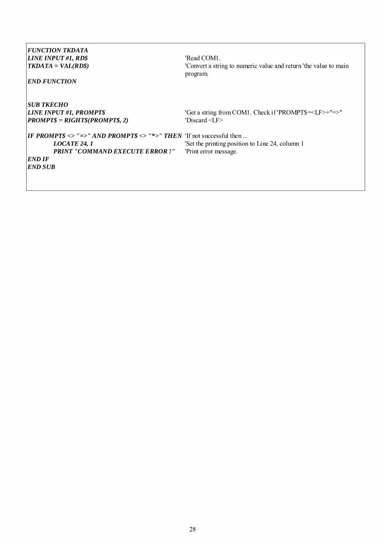
28
FUNCTION TKDATA LINE INPUT #1, RD$ 'Read COM1. TKDATA = VAL(RD$) 'Convert a string to numeric value and return 'the value to main
program. END FUNCTION SUB TKECHO LINE INPUT #1, PROMPT$ 'Get a string from COM1. Check if 'PROMPT$=<LF>+"=>" PROMPT$ = RIGHT$(PROMPT$, 2) 'Discard <LF> IF PROMPT$ <> "=>" AND PROMPT$ <> "*>" THEN 'If not successful then ... LOCATE 24, 1 'Set the printing position to Line 24, column 1 PRINT "COMMAND EXECUTE ERROR !" 'Print error message. END IF END SUB
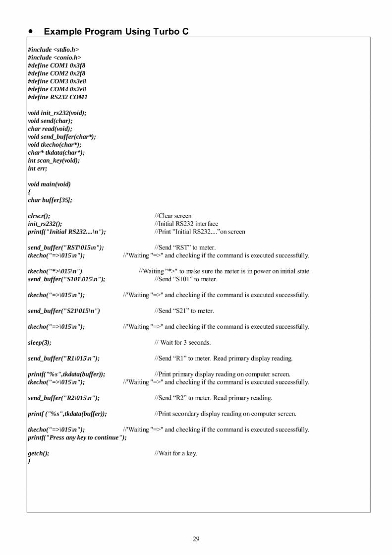
29
Example Program Using Turbo C
#include <stdio.h> #include <conio.h> #define COM1 0x3f8 #define COM2 0x2f8 #define COM3 0x3e8 #define COM4 0x2e8 #define RS232 COM1 void init_rs232(void); void send(char); char read(void); void send_buffer(char*); void tkecho(char*); char* tkdata(char*); int scan_key(void); int err; void main(void) char buffer[35]; clrscr(); //Clear screen init_rs232(); //Initial RS232 interface printf("Initial RS232....\n"); //Print "Initial RS232....”on screen send_buffer("RST\015\n"); //Send “RST” to meter. tkecho("=>\015\n"); //'Waiting "=>" and checking if the command is executed successfully. tkecho("*>\015\n") //Waiting "*>" to make sure the meter is in power on initial state. send_buffer("S101\015\n"); //Send “S101” to meter. tkecho("=>\015\n"); //'Waiting "=>" and checking if the command is executed successfully. send_buffer("S21\015\n") //Send “S21” to meter. tkecho("=>\015\n"); //'Waiting "=>" and checking if the command is executed successfully. sleep(3); // Wait for 3 seconds. send_buffer("R1\015\n"); //Send “R1” to meter. Read primary display reading. printf("%s",tkdata(buffer)); //Print primary display reading on computer screen. tkecho("=>\015\n"); //'Waiting "=>" and checking if the command is executed successfully. send_buffer("R2\015\n"); //Send “R2” to meter. Read primary reading. printf ("%s",tkdata(buffer)); //Print secondary display reading on computer screen. tkecho("=>\015\n"); //'Waiting "=>" and checking if the command is executed successfully. printf("Press any key to continue"); getch(); //Wait for a key.
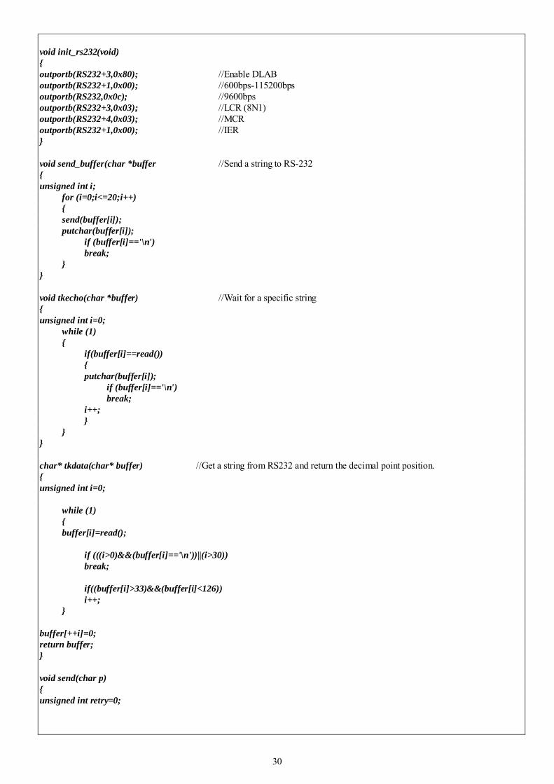
30
void init_rs232(void) outportb(RS232+3,0x80); //Enable DLAB outportb(RS232+1,0x00); //600bps-115200bps outportb(RS232,0x0c); //9600bps outportb(RS232+3,0x03); //LCR (8N1) outportb(RS232+4,0x03); //MCR outportb(RS232+1,0x00); //IER void send_buffer(char *buffer //Send a string to RS-232 unsigned int i; for (i=0;i<=20;i++) send(buffer[i]); putchar(buffer[i]); if (buffer[i]=='\n') break; void tkecho(char *buffer) //Wait for a specific string unsigned int i=0; while (1) if(buffer[i]==read()) putchar(buffer[i]); if (buffer[i]=='\n') break; i++; char* tkdata(char* buffer) //Get a string from RS232 and return the decimal point position. unsigned int i=0; while (1) buffer[i]=read(); if (((i>0)&&(buffer[i]=='\n'))||(i>30)) break; if((buffer[i]>33)&&(buffer[i]<126)) i++; buffer[++i]=0; return buffer; void send(char p) unsigned int retry=0;
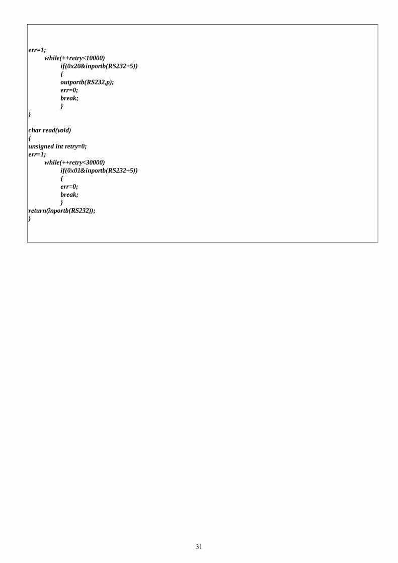
31
err=1; while(++retry<10000) if(0x20&inportb(RS232+5)) outportb(RS232,p); err=0; break; char read(void) unsigned int retry=0; err=1; while(++retry<30000) if(0x01&inportb(RS232+5)) err=0; break; return(inportb(RS232));
32
Section 7 GPIB Remote Operation (Option)
7-1 Introduction
This section describes how to operate the meter via GPIB interface. It also explains the detail information of all IEEE 488.2 command sets and Standard Commands for Programmable Instruments (SCPI) used in the meter. The remote control operation enables the user either to manually operate the meter via a terminal or executes a host computer program automatically. The IEEE-488 interface function subsets of the meter support SH1 (Source Handshake), AH1 (Acceptor Handshake), T5 (Talker), L4 (Listener), SR1 (Service Request), RL1 (Remote/Local), DT1 (Device Trigger) and DC1 (Device Clear).
7-2 Description of the GPIB
The GPIB is a bus structure that links the meter to desktop computers and others GPIB controlled instruments to form an automated measuring system. GPIB can connect up to 15 devices on one contiguous bus, star or linear bus network. Total transmission path length is 2 meters multiplies number of devices, whichever is less, with a maximum of 3 meters separating any two devices. Asynchronous 8 bits parallel data transfer using a 3-wire handshake.
One megabyte per second (maximum) over limited distances; actual data rate depends upon the capability of the slowest device involved in the transmission.
7-3 GPIB Interface Parameters Setup
With the optional GPIB (IEEE-488) interface installed, the meter is fully programmable for used on the IEEE-488.1 interface bus (1978). The meter is also designed to comply with the supplemental standard IEEE-488.2 (1987).
In order to operate the meter via a host computer or terminal, the parameters in GPIB interface within the meter has to match the parameters in the bus interface provided by the host or terminal.
The following procedures will guide you to set up GPIB interface parameters within the meter to comply GPIB interface with the host. The default settings of the meter at factory are address 8 and talk off.
Table 7-1 indicates the GPIB interface factory settings and user selectable communication parameters.

33
Table 7-1. GPIB Interface Parameters Item Parameter Factory Setting Selectable Parameter
1 Address 8 0 to 30
2 Talk OFF ON or OFF
The remote state indication of the meter will be flashing on setting to GPIB Talk ON. The meter auto-asserts the SRQ control line on the GPIB for generating a new reading each second, and reminds another GPIB device to read the newest data. Because the function of GPIB Talk only sends reading data to another GPIB device, the meter doesn’t accept any IEEE 488.2 and SCPI commands.
7-4 Commands Summary
7-4-1 Overview of Command Type and Format All commands must be entered in the upper case. There are two types of the meter programming
commands: IEEE 488.2 common commands and Standard Commands for Programmable Instruments (SCPI). The SCPI commands used in the meter are in conformance with the SCPI standard Version 1993.0.
Common Command Format The IEEE 488.2 standard defines the common commands as commands that perform functions
like reset, self-test and status byte query. Common commands always come with the asterisk “*” character, and may include parameters. Some examples of Common command like: *IDN?, *RST, *CLS, *SRE?.
SCPI Command Format and Query Format The SCPI commands control instrument functions. A subsystem command has a hierarchical
structure that usually consists of a top-level (or root) keyword, one or more lower level keywords, and parameters. The following example shows a command and its associated query:
A. CONFigure:VOLTage:DC 0.5 ; Set the primary display to the DC voltage measurement , and select
the 500mV range. B. CONFigure:RANGe? ; Return the range of the primary display measurement. CONFigure is a root level keyword with the second level keyword, VOLTage, and 0.5 is the
command parameter. The query command ends with a question mark “?”. Note: SCPI stems from IEEE488.1 and IEEE 488.2. Although the IEEE 488.2 standard addressed some instrument measurements, it principally dealt with common commands and syntax or data formats. Please refer to the IEEE488.2 and SCPI reference manual for more information.
7-4-2 Data Types of Responding Message Responding message is the data from the meter in response to a query. A query is a command followed by a question mark. Table 7-2 is explanation for data types.
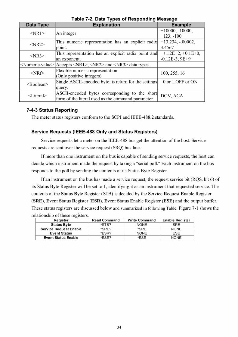
34
Table 7-2. Data Types of Responding Message Data Type Explanation Example
<NR1> An integer +10000, -10000, 123, -100
<NR2> This numeric representation has an explicit radix point.
+13.234, -.00002, 3.4567
<NR3> This representation has an explicit radix point and an exponent.
+1.2E+2, +0.1E+0, -0.12E-3, 9E+9
<Numeric value> Accepts <NR1>, <NR2> and <NR3> data types.
<NRf> Flexible numeric representation (Only positive integers). 100, 255, 16
<Boolean> Single ASCII-encoded byte, is return for the settings query.
0 or 1,OFF or ON
<Literal> ASCII-encoded bytes corresponding to the short form of the literal used as the command parameter. DCV, ACA
7-4-3 Status Reporting The meter status registers conform to the SCPI and IEEE-488.2 standards.
Service Requests (IEEE-488 Only and Status Registers)
Service requests let a meter on the IEEE-488 bus get the attention of the host. Service requests are sent over the service request (SRQ) bus line.
If more than one instrument on the bus is capable of sending service requests, the host can decide which instrument made the request by taking a "serial poll." Each instrument on the bus responds to the poll by sending the contents of its Status Byte Register.
If an instrument on the bus has made a service request, the request service bit (RQS, bit 6) of its Status Byte Register will be set to 1, identifying it as an instrument that requested service. The contents of the Status Byte Register (STB) is decided by the Service Request Enable Register (SRE), Event Status Register (ESR), Event Status Enable Register (ESE) and the output buffer. These status registers are discussed below and summarized in following Table. Figure 7-1 shows the relationship of these registers.
Register Read Command Write Command Enable Register Status Byte *STB? NONE SRE
Service Request Enable *SRE? *SRE NONE Event Status *ESR? NONE ESE
Event Status Enable *ESE? *ESE NONE

35
Figure 7-1. IEEE 488.2 Standard Status Structures
Note: The buffer size of the Output Queue is just one.
Status Byte Register (STB)
Bit7 Bit6 Bit5 Bit4 Bit3 Bit2 Bit1 Bit0 0 RQS/ MSS ESB MAV 0 0 0 0
Bit 0 ~ 3: Not used.
Bit 4: MAV- Message Available
Data is available in the Output Buffer. Bit set to 1 when response to query placed in output buffer. Bit set to 0 when output terminator has sent to host.
Bit 5: ESB – Event Status It’s set to 1 when one or more of enabled events in the Event Status
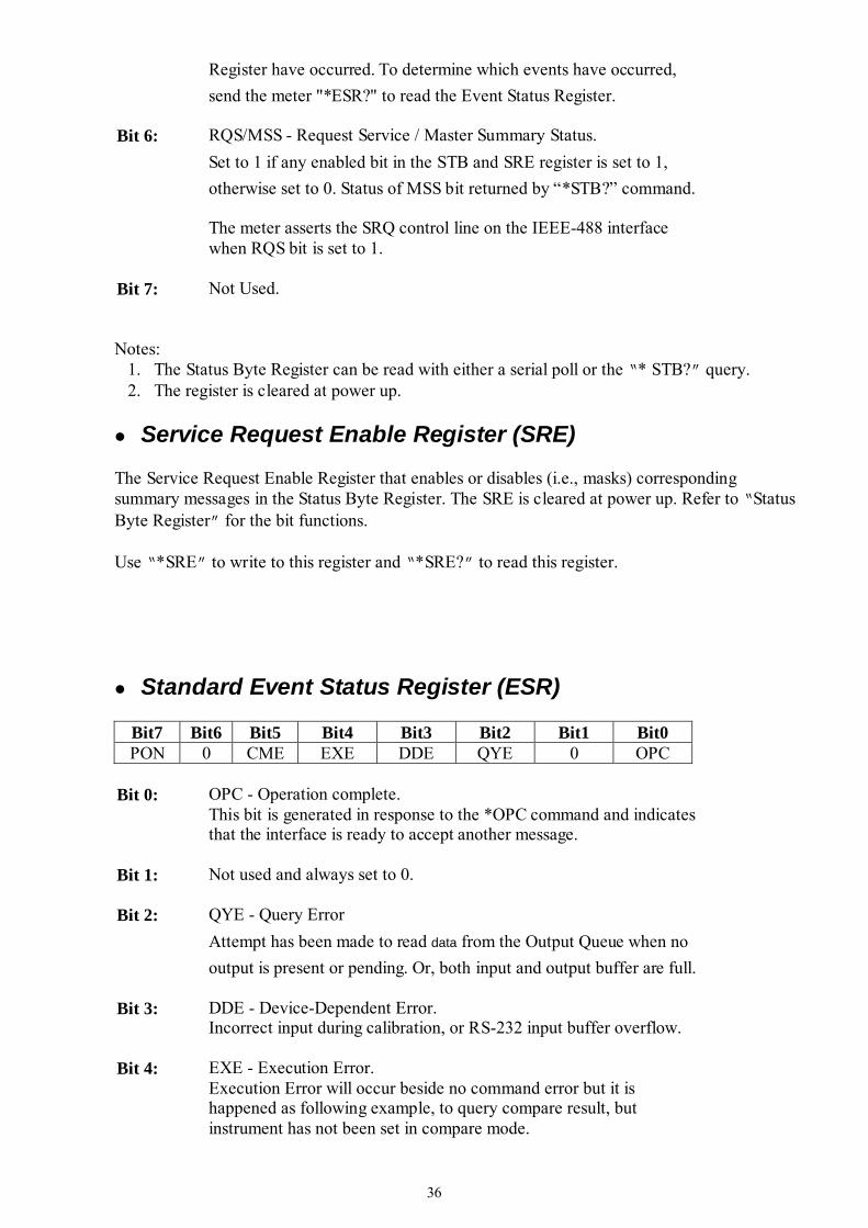
36
Register have occurred. To determine which events have occurred, send the meter "*ESR?" to read the Event Status Register.
Bit 6: RQS/MSS - Request Service / Master Summary Status. Set to 1 if any enabled bit in the STB and SRE register is set to 1, otherwise set to 0. Status of MSS bit returned by “*STB?” command. The meter asserts the SRQ control line on the IEEE-488 interface when RQS bit is set to 1.
Bit 7: Not Used.
Notes:
1. The Status Byte Register can be read with either a serial poll or the “* STB?” query. 2. The register is cleared at power up.
Service Request Enable Register (SRE)
The Service Request Enable Register that enables or disables (i.e., masks) corresponding summary messages in the Status Byte Register. The SRE is cleared at power up. Refer to “Status Byte Register” for the bit functions.
Use “*SRE” to write to this register and “*SRE?” to read this register.
Standard Event Status Register (ESR)
Bit7 Bit6 Bit5 Bit4 Bit3 Bit2 Bit1 Bit0 PON 0 CME EXE DDE QYE 0 OPC
Bit 0: OPC - Operation complete.
This bit is generated in response to the *OPC command and indicates that the interface is ready to accept another message.
Bit 1: Not used and always set to 0.
Bit 2: QYE - Query Error Attempt has been made to read data from the Output Queue when no output is present or pending. Or, both input and output buffer are full.
Bit 3: DDE - Device-Dependent Error. Incorrect input during calibration, or RS-232 input buffer overflow.
Bit 4: EXE - Execution Error. Execution Error will occur beside no command error but it is happened as following example, to query compare result, but instrument has not been set in compare mode.
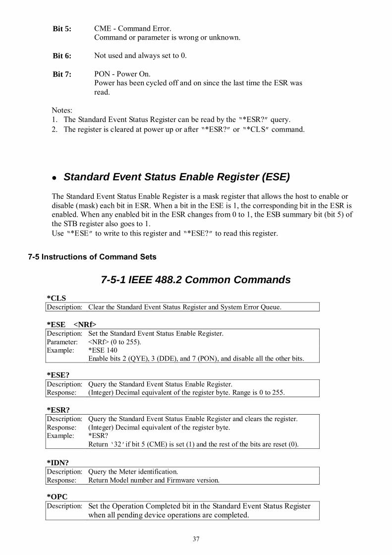
37
Bit 5: CME - Command Error. Command or parameter is wrong or unknown.
Bit 6: Not used and always set to 0.
Bit 7: PON - Power On. Power has been cycled off and on since the last time the ESR was read.
Notes: 1. The Standard Event Status Register can be read by the “*ESR?” query. 2. The register is cleared at power up or after “*ESR?” or “*CLS” command.
Standard Event Status Enable Register (ESE)
The Standard Event Status Enable Register is a mask register that allows the host to enable or disable (mask) each bit in ESR. When a bit in the ESE is 1, the corresponding bit in the ESR is enabled. When any enabled bit in the ESR changes from 0 to 1, the ESB summary bit (bit 5) of the STB register also goes to 1. Use “*ESE” to write to this register and “*ESE?” to read this register.
7-5 Instructions of Command Sets
7-5-1 IEEE 488.2 Common Commands
*CLS Description: Clear the Standard Event Status Register and System Error Queue.
*ESE <NRf> Description: Set the Standard Event Status Enable Register. Parameter: <NRf> (0 to 255). Example: *ESE 140
Enable bits 2 (QYE), 3 (DDE), and 7 (PON), and disable all the other bits.
*ESE? Description: Query the Standard Event Status Enable Register. Response: (Integer) Decimal equivalent of the register byte. Range is 0 to 255.
*ESR? Description: Query the Standard Event Status Enable Register and clears the register. Response: (Integer) Decimal equivalent of the register byte. Example: *ESR?
Return ‘32’if bit 5 (CME) is set (1) and the rest of the bits are reset (0).
*IDN? Description: Query the Meter identification. Response: Return Model number and Firmware version.
*OPC Description: Set the Operation Completed bit in the Standard Event Status Register
when all pending device operations are completed.
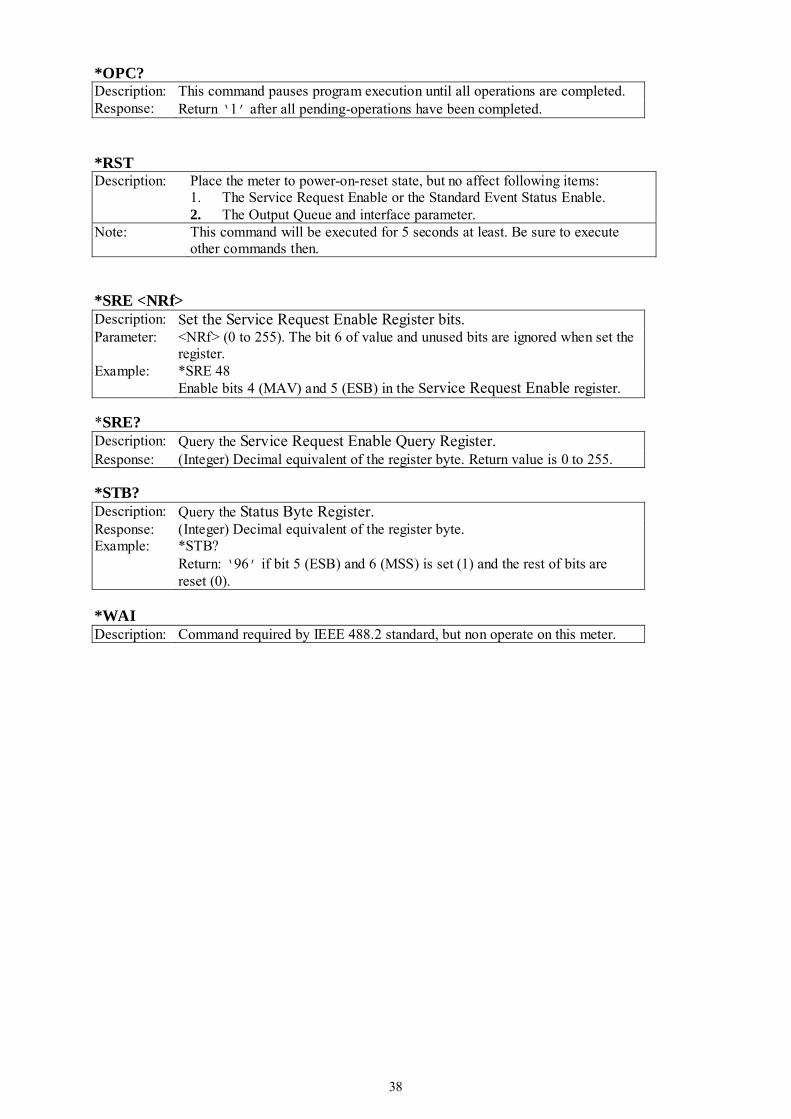
38
*OPC? Description: This command pauses program execution until all operations are completed. Response: Return ‘1’ after all pending-operations have been completed.
*RST Description: Place the meter to power-on-reset state, but no affect following items:
1. The Service Request Enable or the Standard Event Status Enable. 2. The Output Queue and interface parameter.
Note: This command will be executed for 5 seconds at least. Be sure to execute other commands then.
*SRE <NRf> Description: Set the Service Request Enable Register bits. Parameter: <NRf> (0 to 255). The bit 6 of value and unused bits are ignored when set the
register. Example: *SRE 48
Enable bits 4 (MAV) and 5 (ESB) in the Service Request Enable register.
*SRE? Description: Query the Service Request Enable Query Register. Response: (Integer) Decimal equivalent of the register byte. Return value is 0 to 255.
*STB? Description: Query the Status Byte Register. Response: (Integer) Decimal equivalent of the register byte. Example: *STB?
Return: ‘96’ if bit 5 (ESB) and 6 (MSS) is set (1) and the rest of bits are reset (0).
*WAI Description: Command required by IEEE 488.2 standard, but non operate on this meter.
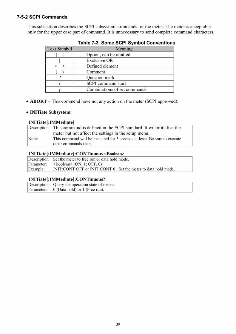
39
7-5-2 SCPI Commands
This subsection describes the SCPI subsystem commands for the meter. The meter is acceptable only for the upper case part of command. It is unnecessary to send complete command characters.
Table 7-3. Some SCPI Symbol Conventions
Text Symbol Meaning [ ] Option; can be omitted
| Exclusive OR < > Defined element ( ) Comment
? Question mark : SCPI command start ; Combinations of set commands
• ABORT – This commend have not any action on the meter (SCPI approved).
• INITiate Subsystem: INITiate[:IMMediate]
Description: This command is defined in the SCPI standard. It will initialize the meter but not affect the settings in the setup menu.
Note: This command will be executed for 5 seconds at least. Be sure to execute other commands then.
INITiate[:IMMediate]:CONTinuous <Boolean>
Description: Set the meter to free run or data hold mode. Parameter: <Boolean> (ON, 1; OFF, 0) Example: INIT:CONT OFF or INIT:CONT 0 ; Set the meter to data hold mode.
INITiate[:IMMediate]:CONTinuous?
Description: Query the operation state of meter. Parameter: 0 (Data hold) or 1 (Free run).

40
• CONFigure Subsystem : CONFigure [:SCALar] :VOLTage :DC [<numeric value>] [ [ ,@1] | ,@2 ] :AC [<numeric value>] [ [ ,@1] | ,@2 ] :ACDC [<numeric value>] [ ,@1] :DCAC [<numeric value>] [ ,@1]
Description: Set the primary and secondary display to DC, AC or AC+DC voltage measurement. The <numeric value> parameter is used to configure the measuring range. [ [@1] | ,@2 ] syntax is same as SCPI <channel_list> syntax.
Parameter: <numeric value>: Measuring range: 0.5, 5, 50, 500, 750, 1000 V. For @2, it is used as frequency function has been set on primary display, otherwise it will be omitted. [ [ ,@1] | ,@2 ]: Use @1 and @2 to distinguish from primary display and secondary display, respectively.
Example: CONF:VOLT:DC ; Set the primary display to DC voltage. CONF:VOLT:AC ,@2 ; Set the secondary display to AC voltage. CONF:VOLT:ACDC 0.5,@1 ; Set the primary display to AC+DC voltage
and 500mV range . CONFigure [:SCALar] :CURRent :DC [<numeric value>] [ [ ,@1] | ,@2 ] :AC [<numeric value>] [ [ ,@1] | ,@2 ] :ACDC [<numeric value>] [ ,@1] :DCAC [<numeric value>] [ ,@1]
Description: Set the primary and secondary display to DC, AC or AC+DC current measurement. The <numeric value> parameter is used to configure the measuring range. [ [@1] | ,@2 ] syntax is same as SCPI <channel_list> syntax.
Parameter: <numeric value>: Measuring range: 5E-4, 5E-3, 0.05, 0.5, 5, 10 A. For @2, it is used as frequency function has been set on primary display, otherwise it will be omitted. [ [ ,@1] | ,@2 ]: Use @1 and @2 to distinguish from primary display and secondary display, respectively.
Example: CONF:CURR:DC ;Set the primary display to DC current. CONF:CURR:AC,@2 ;Set the secondary display to AC current CONF:CURR:ACDC ,@1 ;Set the primary display to AC+DC current.
CONFigure[:SCALar]:DIOCtest Description: Set the primary display to diode with continuity test.
CONFigure[:SCALar]:FREQuency [ [ ,@1] | ,@2 ]
Description: Set the primary and secondary display to frequency measurement. [ [@1] | ,@2 ] syntax is same as SCPI <channel_list> syntax.
Parameter: [ [ ,@1] | ,@2 ]: Use @1 and @2 to distinguish from primary display and secondary display, respectively.
Example: CONF:FREQ ;Set the primary display to frequency test. CONF:FREQ,@2 ;Set the secondary display to frequency test.
Note: The frequency measurement is always keeping on auto-ranging on this model.
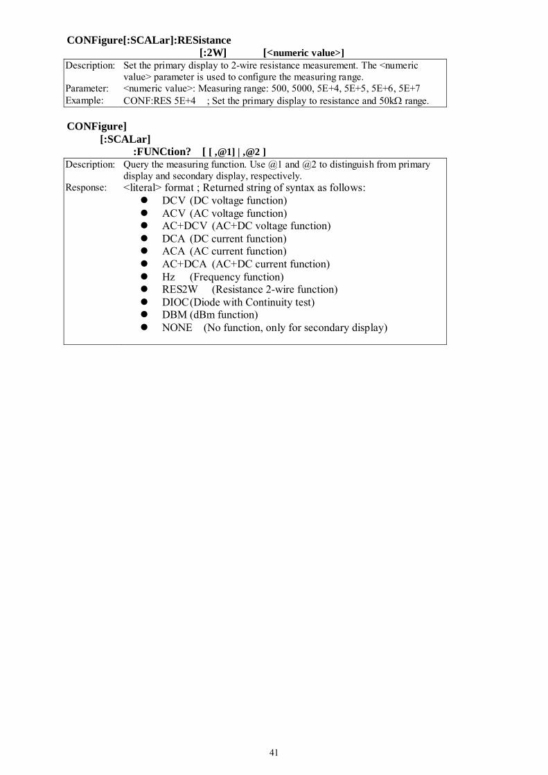
41
CONFigure[:SCALar]:RESistance [:2W] [<numeric value>]
Description: Set the primary display to 2-wire resistance measurement. The <numeric value> parameter is used to configure the measuring range.
Parameter: <numeric value>: Measuring range: 500, 5000, 5E+4, 5E+5, 5E+6, 5E+7 Example: CONF:RES 5E+4 ; Set the primary display to resistance and 50kΩ range.
CONFigure] [:SCALar] :FUNCtion? [ [ ,@1] | ,@2 ]
Description: Query the measuring function. Use @1 and @2 to distinguish from primary display and secondary display, respectively.
Response: <literal> format ; Returned string of syntax as follows: DCV (DC voltage function) ACV (AC voltage function) AC+DCV (AC+DC voltage function) DCA (DC current function) ACA (AC current function) AC+DCA (AC+DC current function) Hz (Frequency function) RES2W (Resistance 2-wire function) DIOC (Diode with Continuity test) DBM (dBm function) NONE (No function, only for secondary display)
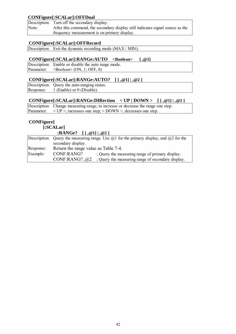
42
CONFigure[:SCALar]:OFFDual Description: Turn off the secondary display. Note: After this command, the secondary display still indicates signal source as the
frequency measurement is on primary display. CONFigure[:SCALar]:OFFRecord
Description: Exit the dynamic recording mode (MAX / MIN). CONFigure[:SCALar]:RANGe:AUTO <Boolean> [ ,@1]
Description: Enable or disable the auto range mode. Parameter: <Boolean> (ON, 1; OFF, 0)
CONFigure[:SCALar]:RANGe:AUTO? [ [ ,@1] | ,@2 ]
Description: Query the auto-ranging status. Response: 1 (Enable) or 0 (Disable).
CONFigure[:SCALar]:RANGe:DIRection < UP | DOWN > [ [ ,@1] | ,@2 ]
Description: Change measuring range, to increase or decrease the range one step. Parameter: < UP >, increases one step; < DOWN >, decreases one step.
CONFigure] [:SCALar] :RANGe? [ [ ,@1] | ,@2 ]
Description: Query the measuring range. Use @1 for the primary display, and @2 for the secondary display.
Response: Return the range value as Table 7-4. Example: CONF:RANG? ; Query the measuring range of primary display.
CONF:RANG? ,@2 ; Query the measuring range of secondary display.
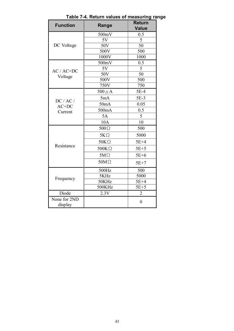
43
Table 7-4. Return values of measuring range
Function Range Return Value
500mV 0.5 5V 5 50V 50 500V 500
DC Voltage
1000V 1000 500mV 0.5
5V 5 50V 50 500V 500
AC / AC+DC Voltage
750V 750 500μA 5E-4
5mA 5E-3 50mA 0.05 500mA 0.5
5A 5
DC / AC / AC+DC Current
10A 10 500Ω 500 5KΩ 5000 50KΩ 5E+4 500KΩ 5E+5 5MΩ 5E+6
Resistance
50MΩ 5E+7 500Hz 500 5KHz 5000 50KHz 5E+4
Frequency
500KHz 5E+5 Diode 2.3V 2
None for 2ND display
0
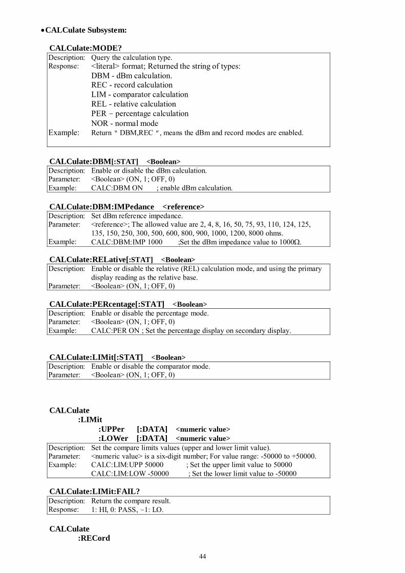
44
•CALCulate Subsystem: CALCulate:MODE?
Description: Query the calculation type. Response: <literal> format; Returned the string of types:
DBM - dBm calculation. REC - record calculation LIM - comparator calculation REL - relative calculation PER – percentage calculation NOR - normal mode
Example: Return “ DBM,REC ”, means the dBm and record modes are enabled.
CALCulate:DBM[:STAT] <Boolean>
Description: Enable or disable the dBm calculation. Parameter: <Boolean> (ON, 1; OFF, 0) Example: CALC:DBM ON ; enable dBm calculation.
CALCulate:DBM:IMPedance <reference> Description: Set dBm reference impedance. Parameter: <reference>; The allowed value are 2, 4, 8, 16, 50, 75, 93, 110, 124, 125,
135, 150, 250, 300, 500, 600, 800, 900, 1000, 1200, 8000 ohms. Example: CALC:DBM:IMP 1000 ;Set the dBm impedance value to 1000Ω.
CALCulate:RELative[:STAT] <Boolean>
Description: Enable or disable the relative (REL) calculation mode, and using the primary display reading as the relative base.
Parameter: <Boolean> (ON, 1; OFF, 0) CALCulate:PERcentage[:STAT] <Boolean>
Description: Enable or disable the percentage mode. Parameter: <Boolean> (ON, 1; OFF, 0) Example: CALC:PER ON ; Set the percentage display on secondary display.
CALCulate:LIMit[:STAT] <Boolean> Description: Enable or disable the comparator mode. Parameter: <Boolean> (ON, 1; OFF, 0)
CALCulate :LIMit :UPPer [:DATA] <numeric value> :LOWer [:DATA] <numeric value>
Description: Set the compare limits values (upper and lower limit value). Parameter: <numeric value> is a six-digit number; For value range: -50000 to +50000. Example: CALC:LIM:UPP 50000 ; Set the upper limit value to 50000
CALC:LIM:LOW -50000 ; Set the lower limit value to -50000
CALCulate:LIMit:FAIL? Description: Return the compare result. Response: 1: HI, 0: PASS, –1: LO.
CALCulate :RECord
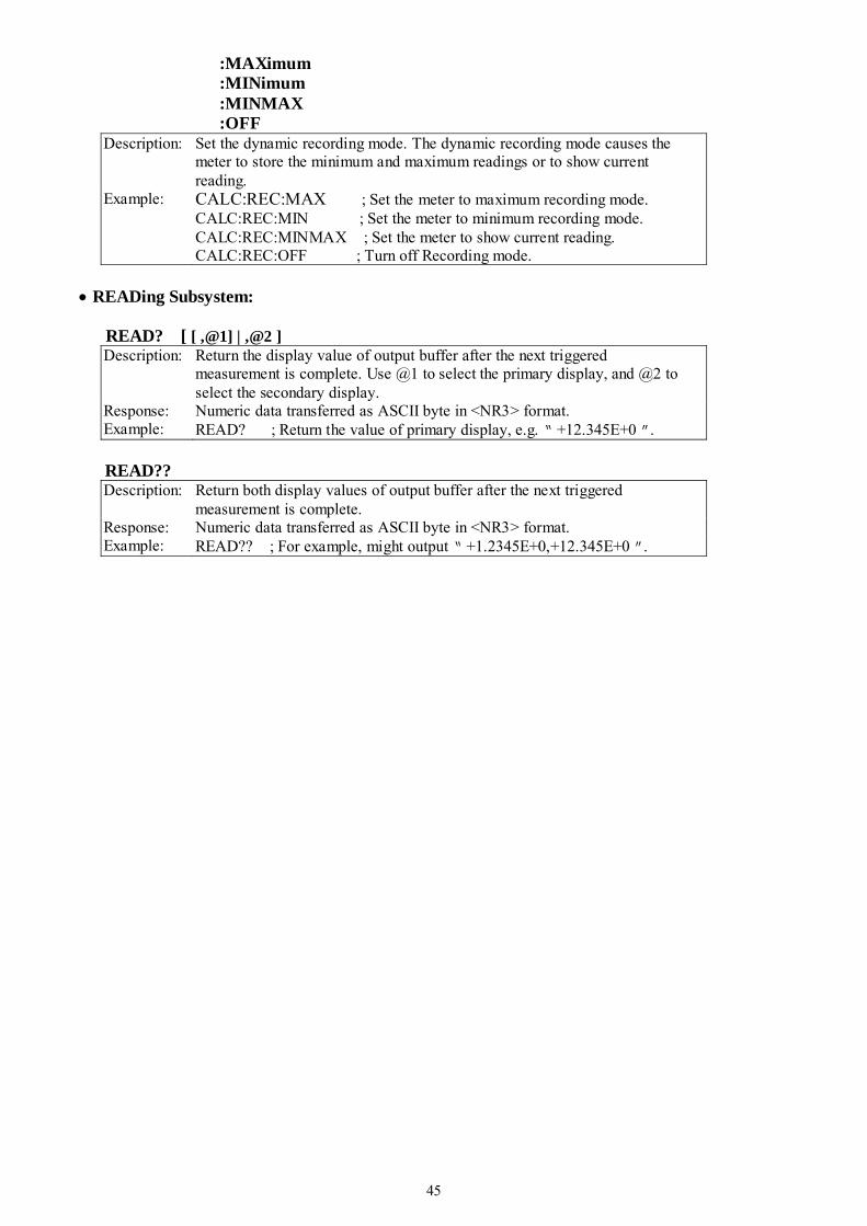
45
:MAXimum :MINimum :MINMAX :OFF
Description: Set the dynamic recording mode. The dynamic recording mode causes the meter to store the minimum and maximum readings or to show current reading.
Example: CALC:REC:MAX ; Set the meter to maximum recording mode. CALC:REC:MIN ; Set the meter to minimum recording mode. CALC:REC:MINMAX ; Set the meter to show current reading. CALC:REC:OFF ; Turn off Recording mode.
• READing Subsystem: READ? [ [ ,@1] | ,@2 ]
Description: Return the display value of output buffer after the next triggered measurement is complete. Use @1 to select the primary display, and @2 to select the secondary display.
Response: Numeric data transferred as ASCII byte in <NR3> format. Example: READ? ; Return the value of primary display, e.g. “ +12.345E+0 ”.
READ??
Description: Return both display values of output buffer after the next triggered measurement is complete.
Response: Numeric data transferred as ASCII byte in <NR3> format. Example: READ?? ; For example, might output “ +1.2345E+0,+12.345E+0 ”.

46
• TRIGger Subsystem: TRIGger:SOURce <BUS| IMMediate >
Description: Selects the source of the start trigger signal. (SCPI approved). Parameter: BUS - Selects a bus command and enter single trigger mode.
IMMediate - Selects the internal trigger source and escape single trigger mode.
Example: TRIG:SOUR BUS Select a bus command as the trigger source then trigger a measurement.
TRIGger:SOURce?
Description: Queries the trigger source type (SCPI approved). Response: <literal> format ; Return the type string : BUS, IMM
MEASure?
Description: Causes the meter to trigger a measurement and then output it. Response: Numeric data transferred as ASCII byte in <NR3> format. Example: MEAS? ; Meter returns the value shown on the primary display.
• SYSTem Subsystem : (SCPI approved).
SYSTem:VERSion?
Description: Return the firmware version of the meter. SYSTem:ERRor?
Description: Return the next message from the system error queue. Response: <string> format, Table 7-5 is a list of SCPI error message that might occur
during operation.
Table 7-5. SCPI Error Message Number Error String Number Error String
0 No error -108 Parameter not allowed -100 Command error -109 Missing parameter -102 Syntax error -200 Execution error -103 Invalid separator -222 Data out of range -104 Data type error -224 Illegal parameter value
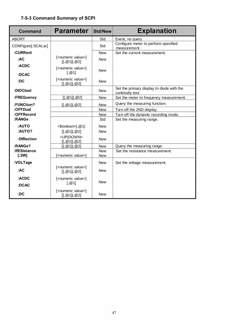
47
7-5-3 Command Summary of SCPI
Command Parameter Std/New Explanation ABORT Std Event, no query
CONFigure[:SCALar] Std Configure meter to perform specified measurement.
:CURRent New Set the current measurement. :AC [<numeric value>]
[[,@1]|,@2] New
:ACDC :DCAC
[<numeric value>] [,@1] New
:DC [<numeric value>] [[,@1]|,@2] New
:DIOCtest New Set the primary display to diode with the continuity test.
:FREQuency [[,@1]|,@2] New Set the meter to frequency measurement.
:FUNCtion? [[,@1]|,@2] New Query the measuring function. :OFFDual New Turn off the 2ND display. :OFFRecord New Turn off the dynamic recording mode. :RANGe Std Set the measuring range.
:AUTO <Boolean>[,@1] New :AUTO? [[,@1]|,@2] New
:DIRection <UP|DOWN> [[,@1]|,@2] New
:RANGe? [[,@1]|,@2] New Query the measuring range. :RESistance New Set the resistance measurement. [:2W] [<numeric value>] New
:VOLTage New Set the voltage measurement.
:AC [<numeric value>]
[[,@1]|,@2] New
:ACDC
:DCAC
[<numeric value>] [,@1] New
:DC [<numeric value>]
[[,@1]|,@2] New
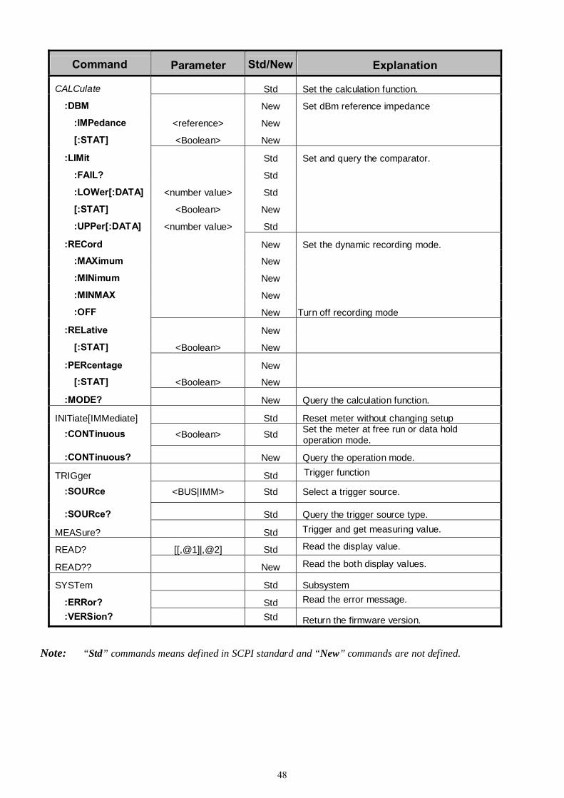
48
Command Parameter Std/New Explanation
CALCulate Std Set the calculation function.
:DBM New Set dBm reference impedance
:IMPedance <reference> New
[:STAT] <Boolean> New
:LIMit Std Set and query the comparator.
:FAIL? Std
:LOWer[:DATA] <number value> Std
[:STAT] <Boolean> New
:UPPer[:DATA] <number value> Std
:RECord New Set the dynamic recording mode.
:MAXimum New
:MINimum New
:MINMAX New
:OFF New Turn off recording mode
:RELative New
[:STAT] <Boolean> New
:PERcentage New
[:STAT] <Boolean> New
:MODE? New Query the calculation function.
INITiate[IMMediate] Std Reset meter without changing setup :CONTinuous <Boolean> Std Set the meter at free run or data hold
operation mode.
:CONTinuous? New Query the operation mode.
TRIGger Std Trigger function
:SOURce <BUS|IMM> Std Select a trigger source.
:SOURce? Std Query the trigger source type.
MEASure? Std Trigger and get measuring value.
READ? [[,@1]|,@2] Std Read the display value.
READ?? New Read the both display values.
SYSTem Std Subsystem
:ERRor? Std Read the error message.
:VERSion? Std Return the firmware version.
Note: “Std” commands means defined in SCPI standard and “New” commands are not defined.

49
7-6 Remote Program Examples using GPIB interface
Example Using Quick BASIC '
GPIBEXAMPLE.BAS ' ' This sample program is for reference only. It can only be expected to ' function with a Digital Multimeter. ' ' This program reads 10 measurements from the meter and averages ' the sum. ' ' The status variables IBSTA%, IBERR%, and IBCNT% are defined in QBDECL.BAS. ' Each bit of IBSTA% and each value of IBERR% are defined in QBDECL.BAS as ' a mnemonic constant for easy recognition in application programs. In this ' example, these mnemonic definitions are logically ANDed with the variable ' IBSTA% to determine if a particular bit has been set. The mnemonic ' definitions are equated with the variable IBERR% to determine the error ' code. ' ' The subroutine GPIBERR is called when a NI-488 function fails. The ' error message is printed along with the status variables IBSTA%, IBERR%, ' and IBCNT%. The subroutine DVMERR is called when the serial poll response ' byte indicates the meter does not have valid data to send. The error ' message and the serial poll response byte are printed. ' ' The NI-488 function IBONL is called from the main body of the program or ' from the two subroutines, GPIBERR and DVMERR. When the second parameter ' of the function IBONL is zero, the software and hardware are disabled. ' Execution of this program is terminated after the call to the function ' IBONL to disable the software and hardware. ' ' The STOP command or END command will terminate this program. '========================================================================= ' QBDECL.BAS contains constants, declarations, and subroutine prototypes. REM $INCLUDE: 'qbdecl.bas' ' GPIBERR is an error subroutine that is called when a NI-488 function fails. ' DVMERR is an error subroutine that is called when the meter does not ' have valid data to send. DECLARE SUB gpiberr (msg$) DECLARE SUB dvmerr (msg$, spr%) CLS PRINT "Read 10 measurements from the meter..." PRINT ' Assign a unique identifier to the meter and store in the variable ' DVM. IBDEV opens an available device and assigns it to access GPIB0 ' with a primary address of 8, a secondary address of 0, a timeout of ' 30 seconds, the END message enabled, and the EOS mode disabled. ' If DVM is less than zero, call GPIBERR with an error message. CALL ibdev(0, 8, 0, T30s, 1, 0, dvm%)
IF (dvm% < 0) THEN CALL gpiberr("Ibdev Error") ' Clear the internal or device functions of the meter. If the error bit ' EERR is set in IBSTA%, call GPIBERR with an error message.
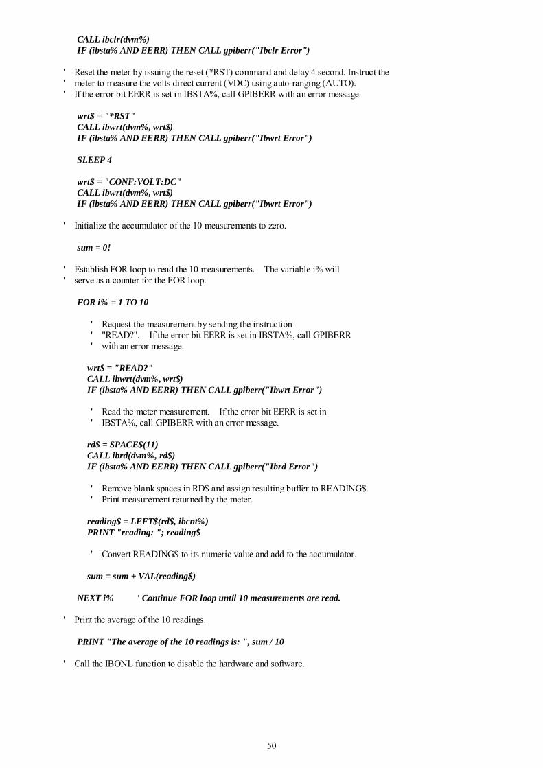
50
CALL ibclr(dvm%) IF (ibsta% AND EERR) THEN CALL gpiberr("Ibclr Error") ' Reset the meter by issuing the reset (*RST) command and delay 4 second. Instruct the ' meter to measure the volts direct current (VDC) using auto-ranging (AUTO). ' If the error bit EERR is set in IBSTA%, call GPIBERR with an error message. wrt$ = "*RST" CALL ibwrt(dvm%, wrt$) IF (ibsta% AND EERR) THEN CALL gpiberr("Ibwrt Error") SLEEP 4 wrt$ = "CONF:VOLT:DC" CALL ibwrt(dvm%, wrt$) IF (ibsta% AND EERR) THEN CALL gpiberr("Ibwrt Error") ' Initialize the accumulator of the 10 measurements to zero. sum = 0! ' Establish FOR loop to read the 10 measurements. The variable i% will ' serve as a counter for the FOR loop. FOR i% = 1 TO 10 ' Request the measurement by sending the instruction ' "READ?". If the error bit EERR is set in IBSTA%, call GPIBERR ' with an error message. wrt$ = "READ?" CALL ibwrt(dvm%, wrt$) IF (ibsta% AND EERR) THEN CALL gpiberr("Ibwrt Error") ' Read the meter measurement. If the error bit EERR is set in ' IBSTA%, call GPIBERR with an error message. rd$ = SPACE$(11) CALL ibrd(dvm%, rd$) IF (ibsta% AND EERR) THEN CALL gpiberr("Ibrd Error") ' Remove blank spaces in RD$ and assign resulting buffer to READING$. ' Print measurement returned by the meter. reading$ = LEFT$(rd$, ibcnt%) PRINT "reading: "; reading$ ' Convert READING$ to its numeric value and add to the accumulator. sum = sum + VAL(reading$) NEXT i% ' Continue FOR loop until 10 measurements are read. ' Print the average of the 10 readings. PRINT "The average of the 10 readings is: ", sum / 10 ' Call the IBONL function to disable the hardware and software.
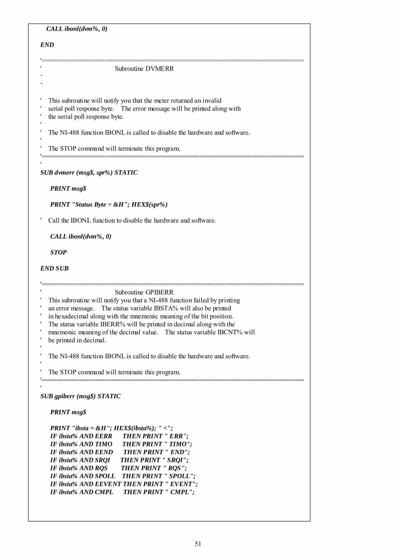
51
CALL ibonl(dvm%, 0) END '====================================================================== ' Subroutine DVMERR ‘ ‘ ' This subroutine will notify you that the meter returned an invalid ' serial poll response byte. The error message will be printed along with ' the serial poll response byte. ' ' The NI-488 function IBONL is called to disable the hardware and software. ' ' The STOP command will terminate this program. '====================================================================== ' SUB dvmerr (msg$, spr%) STATIC PRINT msg$ PRINT "Status Byte = &H"; HEX$(spr%) ' Call the IBONL function to disable the hardware and software. CALL ibonl(dvm%, 0) STOP END SUB '====================================================================== ' Subroutine GPIBERR ' This subroutine will notify you that a NI-488 function failed by printing ' an error message. The status variable IBSTA% will also be printed ' in hexadecimal along with the mnemonic meaning of the bit position. ' The status variable IBERR% will be printed in decimal along with the ' mnemonic meaning of the decimal value. The status variable IBCNT% will ' be printed in decimal. ' ' The NI-488 function IBONL is called to disable the hardware and software. ' ' The STOP command will terminate this program. '====================================================================== ' SUB gpiberr (msg$) STATIC PRINT msg$ PRINT "ibsta = &H"; HEX$(ibsta%); " <"; IF ibsta% AND EERR THEN PRINT " ERR"; IF ibsta% AND TIMO THEN PRINT " TIMO"; IF ibsta% AND EEND THEN PRINT " END"; IF ibsta% AND SRQI THEN PRINT " SRQI"; IF ibsta% AND RQS THEN PRINT " RQS"; IF ibsta% AND SPOLL THEN PRINT " SPOLL"; IF ibsta% AND EEVENT THEN PRINT " EVENT"; IF ibsta% AND CMPL THEN PRINT " CMPL";
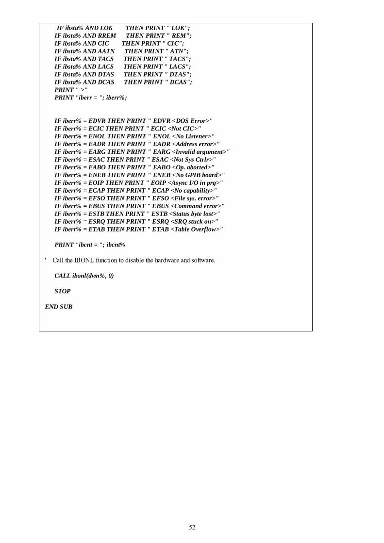
52
IF ibsta% AND LOK THEN PRINT " LOK"; IF ibsta% AND RREM THEN PRINT " REM"; IF ibsta% AND CIC THEN PRINT " CIC"; IF ibsta% AND AATN THEN PRINT " ATN"; IF ibsta% AND TACS THEN PRINT " TACS"; IF ibsta% AND LACS THEN PRINT " LACS"; IF ibsta% AND DTAS THEN PRINT " DTAS"; IF ibsta% AND DCAS THEN PRINT " DCAS"; PRINT " >" PRINT "iberr = "; iberr%; IF iberr% = EDVR THEN PRINT " EDVR <DOS Error>" IF iberr% = ECIC THEN PRINT " ECIC <Not CIC>" IF iberr% = ENOL THEN PRINT " ENOL <No Listener>" IF iberr% = EADR THEN PRINT " EADR <Address error>" IF iberr% = EARG THEN PRINT " EARG <Invalid argument>" IF iberr% = ESAC THEN PRINT " ESAC <Not Sys Ctrlr>" IF iberr% = EABO THEN PRINT " EABO <Op. aborted>" IF iberr% = ENEB THEN PRINT " ENEB <No GPIB board>" IF iberr% = EOIP THEN PRINT " EOIP <Async I/O in prg>" IF iberr% = ECAP THEN PRINT " ECAP <No capability>" IF iberr% = EFSO THEN PRINT " EFSO <File sys. error>" IF iberr% = EBUS THEN PRINT " EBUS <Command error>" IF iberr% = ESTB THEN PRINT " ESTB <Status byte lost>" IF iberr% = ESRQ THEN PRINT " ESRQ <SRQ stuck on>" IF iberr% = ETAB THEN PRINT " ETAB <Table Overflow>" PRINT "ibcnt = "; ibcnt% ' Call the IBONL function to disable the hardware and software. CALL ibonl(dvm%, 0) STOP END SUB

53
Appendix A Specifications
A-1 Introduction Appendix A describes the complete specifications of this meter.
A-2 Technical Specifications
Specifications assumptions: • One-year calibration cycle. • Operating temperature at 18°C to 28°C (64.4°F to 82.4°F). • Accuracy is expressed as: ± (% of reading + digits) after 30 minutes warm-up. • Temperature coefficient: Add ± [0.15 x (the applicable accuracy)/°C] for 0°C to 18°C
and 28°C to 50°C. • Relative Humidity (RH): up to 80% (60% for 50MΩ range of resistance
measurement). • All specifications are specified under single display mode in operation only.
Display Counts and Reading Rates Full Scale Display Counts: 51,000 Counts Reading Rate (Approx.) Measuring Function Readings/Sec Measuring Function Readings/Sec
DCV 3 DCV / Frequency 1.3/2
DCA 3 ACV / Frequency 3/2
Diode 3 ACV+DCV / Frequency 1.3/2
ACV 3 DCA / ACA 1.3
ACA 3 ACA+DCA / DCA 1.3
Ω 3 ACA+DCA / ACA 1.3
Frequency/ACV or ACA 2/3 DCA / Frequency 1.3/2
ACV+DCV 1.3 ACA / Frequency 3/2
ACA+DCA 1.3 ACA+DCA / Frequency 1.3/2
DCV / ACV 1.3 dBm / DCV 3
ACV+DCV / DCV 1.3 dBm / ACV 3
ACV+DCV / ACV 1.3 dBm / ACV+DCV 1.3
Notes: 1. The reading rate is measured as above combinations and applications at lock range. 2. Using RS-232 or GPIB remote interface, the reading rate is similar to normal mode.
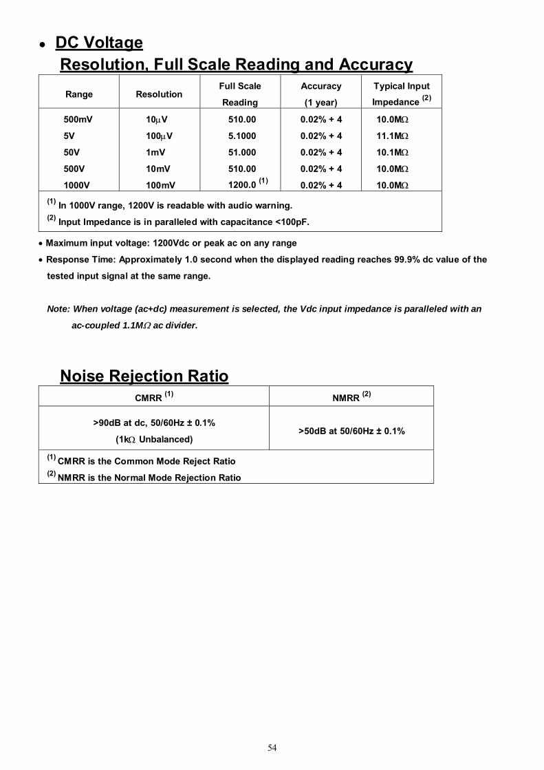
54
DC Voltage Resolution, Full Scale Reading and Accuracy
Range Resolution Full Scale
Reading
Accuracy
(1 year)
Typical Input
Impedance (2)
500mV
5V
50V
500V
1000V
10μV
100μV
1mV
10mV
100mV
510.00
5.1000
51.000
510.00
1200.0 (1)
0.02% + 4
0.02% + 4
0.02% + 4
0.02% + 4
0.02% + 4
10.0MΩ
11.1MΩ
10.1MΩ
10.0MΩ
10.0MΩ (1) In 1000V range, 1200V is readable with audio warning. (2) Input Impedance is in paralleled with capacitance <100pF.
• Maximum input voltage: 1200Vdc or peak ac on any range
• Response Time: Approximately 1.0 second when the displayed reading reaches 99.9% dc value of the
tested input signal at the same range.
Note: When voltage (ac+dc) measurement is selected, the Vdc input impedance is paralleled with an
ac-coupled 1.1MΩ ac divider.
Noise Rejection Ratio CMRR (1) NMRR (2)
>90dB at dc, 50/60Hz ± 0.1%
(1kΩ Unbalanced) >50dB at 50/60Hz ± 0.1%
(1) CMRR is the Common Mode Reject Ratio (2) NMRR is the Normal Mode Rejection Ratio
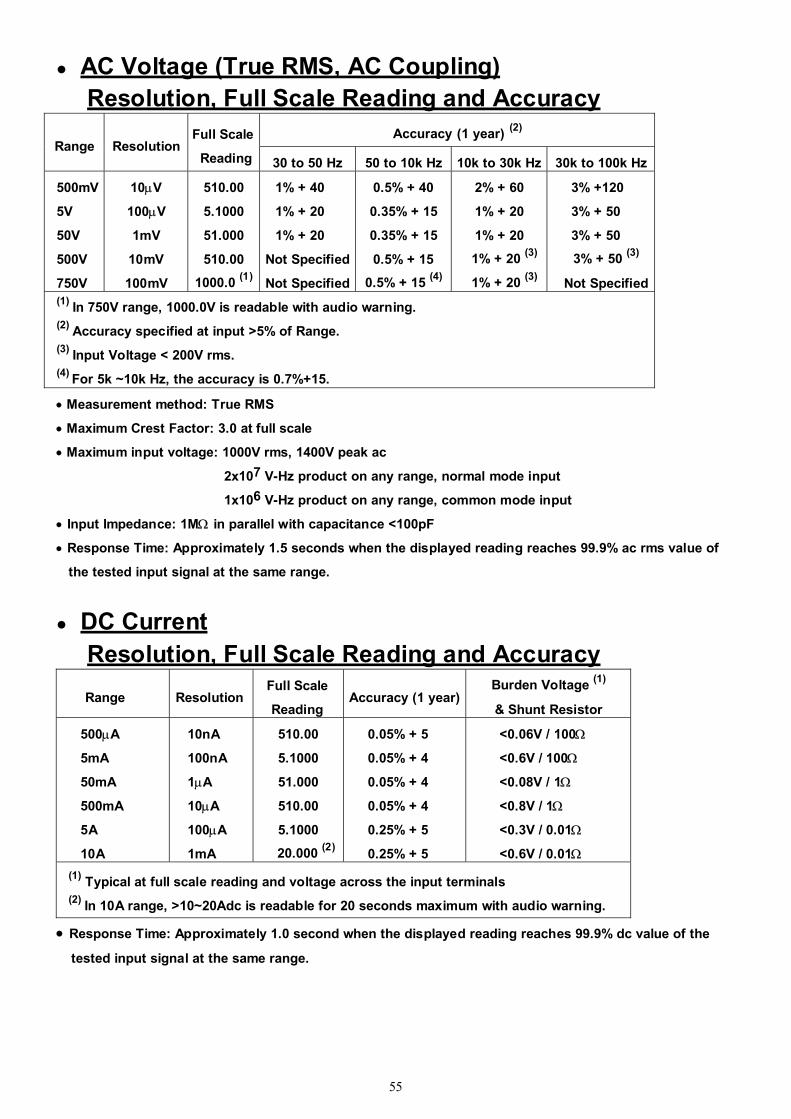
55
AC Voltage (True RMS, AC Coupling) Resolution, Full Scale Reading and Accuracy
Accuracy (1 year) (2) Range Resolution
Full Scale
Reading 30 to 50 Hz 50 to 10k Hz 10k to 30k Hz 30k to 100k Hz
500mV
5V
50V
500V
750V
10μV
100μV
1mV
10mV
100mV
510.00
5.1000
51.000
510.00
1000.0 (1)
1% + 40
1% + 20
1% + 20
Not Specified
Not Specified
0.5% + 40
0.35% + 15
0.35% + 15
0.5% + 15
0.5% + 15 (4)
2% + 60
1% + 20
1% + 20
1% + 20 (3)
1% + 20 (3)
3% +120
3% + 50
3% + 50
3% + 50 (3)
Not Specified (1) In 750V range, 1000.0V is readable with audio warning. (2) Accuracy specified at input >5% of Range. (3) Input Voltage < 200V rms. (4) For 5k ~10k Hz, the accuracy is 0.7%+15.
• Measurement method: True RMS
• Maximum Crest Factor: 3.0 at full scale
• Maximum input voltage: 1000V rms, 1400V peak ac
2x10⁷ V-Hz product on any range, normal mode input
1x10⁶ V-Hz product on any range, common mode input
• Input Impedance: 1MΩ in parallel with capacitance <100pF
• Response Time: Approximately 1.5 seconds when the displayed reading reaches 99.9% ac rms value of
the tested input signal at the same range.
DC Current Resolution, Full Scale Reading and Accuracy Range Resolution
Full Scale
Reading Accuracy (1 year)
Burden Voltage (1)
& Shunt Resistor
500μA
5mA
50mA
500mA
5A
10A
10nA
100nA
1μA
10μA
100μA
1mA
510.00
5.1000
51.000
510.00
5.1000
20.000 (2)
0.05% + 5
0.05% + 4
0.05% + 4
0.05% + 4
0.25% + 5
0.25% + 5
<0.06V / 100Ω
<0.6V / 100Ω
<0.08V / 1Ω
<0.8V / 1Ω
<0.3V / 0.01Ω
<0.6V / 0.01Ω (1) Typical at full scale reading and voltage across the input terminals (2) In 10A range, >10~20Adc is readable for 20 seconds maximum with audio warning.
• Response Time: Approximately 1.0 second when the displayed reading reaches 99.9% dc value of the
tested input signal at the same range.
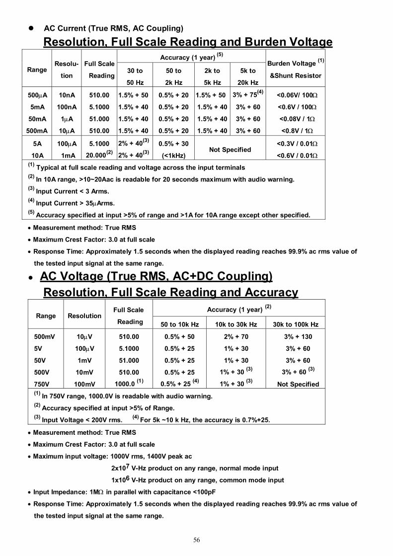
56
AC Current (True RMS, AC Coupling)
Resolution, Full Scale Reading and Burden Voltage Accuracy (1 year) (5)
Range Resolu-
tion
Full Scale
Reading 30 to
50 Hz
50 to
2k Hz
2k to
5k Hz
5k to
20k Hz
Burden Voltage (1)
&Shunt Resistor
500μA
5mA
50mA
500mA
10nA
100nA
1μA
10μA
510.00
5.1000
51.000
510.00
1.5% + 50
1.5% + 40
1.5% + 40
1.5% + 40
0.5% + 20
0.5% + 20
0.5% + 20
0.5% + 20
1.5% + 50
1.5% + 40
1.5% + 40
1.5% + 40
3% + 75(4)
3% + 60
3% + 60
3% + 60
<0.06V/ 100Ω
<0.6V / 100Ω
<0.08V / 1Ω
<0.8V / 1Ω
5A
10A
100μA
1mA
5.1000
20.000(2)
2% + 40(3)
2% + 40(3)
0.5% + 30
(<1kHz) Not Specified
<0.3V / 0.01Ω
<0.6V / 0.01Ω (1) Typical at full scale reading and voltage across the input terminals (2) In 10A range, >10~20Aac is readable for 20 seconds maximum with audio warning. (3) Input Current < 3 Arms. (4) Input Current > 35μArms.
(5) Accuracy specified at input >5% of range and >1A for 10A range except other specified.
• Measurement method: True RMS
• Maximum Crest Factor: 3.0 at full scale
• Response Time: Approximately 1.5 seconds when the displayed reading reaches 99.9% ac rms value of
the tested input signal at the same range.
AC Voltage (True RMS, AC+DC Coupling) Resolution, Full Scale Reading and Accuracy
Accuracy (1 year) (2) Range Resolution
Full Scale
Reading 50 to 10k Hz 10k to 30k Hz 30k to 100k Hz
500mV
5V
50V
500V
750V
10μV
100μV
1mV
10mV
100mV
510.00
5.1000
51.000
510.00
1000.0 (1)
0.5% + 50
0.5% + 25
0.5% + 25
0.5% + 25
0.5% + 25 (4)
2% + 70
1% + 30
1% + 30
1% + 30 (3)
1% + 30 (3)
3% + 130
3% + 60
3% + 60
3% + 60 (3)
Not Specified (1) In 750V range, 1000.0V is readable with audio warning. (2) Accuracy specified at input >5% of Range. (3) Input Voltage < 200V rms. (4) For 5k ~10 k Hz, the accuracy is 0.7%+25.
• Measurement method: True RMS
• Maximum Crest Factor: 3.0 at full scale
• Maximum input voltage: 1000V rms, 1400V peak ac
2x10⁷ V-Hz product on any range, normal mode input
1x10⁶ V-Hz product on any range, common mode input
• Input Impedance: 1MΩ in parallel with capacitance <100pF
• Response Time: Approximately 1.5 seconds when the displayed reading reaches 99.9% ac rms value of
the tested input signal at the same range.
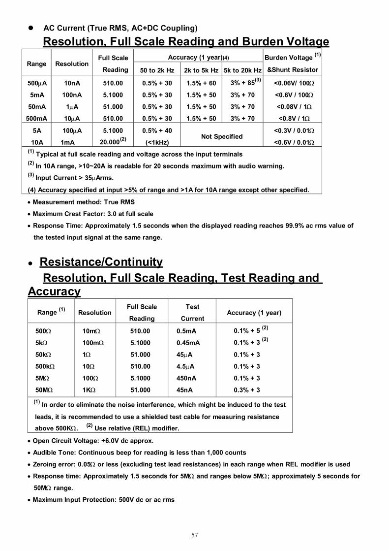
57
AC Current (True RMS, AC+DC Coupling)
Resolution, Full Scale Reading and Burden Voltage Accuracy (1 year)(4)
Range Resolution Full Scale
Reading 50 to 2k Hz 2k to 5k Hz 5k to 20k Hz
Burden Voltage (1)
&Shunt Resistor
500μA
5mA
50mA
500mA
10nA
100nA
1μA
10μA
510.00
5.1000
51.000
510.00
0.5% + 30
0.5% + 30
0.5% + 30
0.5% + 30
1.5% + 60
1.5% + 50
1.5% + 50
1.5% + 50
3% + 85(3)
3% + 70
3% + 70
3% + 70
<0.06V/ 100Ω
<0.6V / 100Ω
<0.08V / 1Ω
<0.8V / 1Ω
5A
10A
100μA
1mA
5.1000
20.000(2)
0.5% + 40
(<1kHz) Not Specified
<0.3V / 0.01Ω
<0.6V / 0.01Ω (1) Typical at full scale reading and voltage across the input terminals (2) In 10A range, >10~20A is readable for 20 seconds maximum with audio warning. (3) Input Current > 35μArms.
(4) Accuracy specified at input >5% of range and >1A for 10A range except other specified.
• Measurement method: True RMS
• Maximum Crest Factor: 3.0 at full scale
• Response Time: Approximately 1.5 seconds when the displayed reading reaches 99.9% ac rms value of
the tested input signal at the same range.
Resistance/Continuity Resolution, Full Scale Reading, Test Reading and
Accuracy Range (1) Resolution
Full Scale
Reading
Test
Current Accuracy (1 year)
500Ω
5kΩ
50kΩ
500kΩ
5MΩ
50MΩ
10mΩ
100mΩ
1Ω
10Ω
100Ω
1KΩ
510.00
5.1000
51.000
510.00
5.1000
51.000
0.5mA
0.45mA
45μA
4.5μA
450nA
45nA
0.1% + 5 (2)
0.1% + 3 (2)
0.1% + 3
0.1% + 3
0.1% + 3
0.3% + 3 (1) In order to eliminate the noise interference, which might be induced to the test
leads, it is recommended to use a shielded test cable for measuring resistance
above 500KΩ. (2) Use relative (REL) modifier.
• Open Circuit Voltage: +6.0V dc approx.
• Audible Tone: Continuous beep for reading is less than 1,000 counts
• Zeroing error: 0.05Ω or less (excluding test lead resistances) in each range when REL modifier is used
• Response time: Approximately 1.5 seconds for 5MΩ and ranges below 5MΩ; approximately 5 seconds for
50MΩ range.
• Maximum Input Protection: 500V dc or ac rms

58
Diode Test/Continuity
Resolution, Full Scale Reading and Accuracy Range Resolution Full Scale Reading Accuracy
2.3V 100μV 2.3000V 0.05% + 5
• Open Circuit Voltage / Test Current: +6.0V dc / 0.5mA approx.
• Audible Tone: Continuous beep for continuity and single tone for normal forward-biased diode or
semiconductor junction
• Continuity level: Approximately below +50mVdc
• Maximum Input Protection: 500V dc or ac rms
Frequency Resolution, Full Scale Reading and Accuracy
Range Measuring
Range Resolution
Full Scale
Reading Accuracy (1 year)
500 Hz 5Hz~ 500Hz 0.01 Hz 510.00 0.01 + 5
5kHz 500Hz~5kHz 0.1 Hz 5.1000 0.01 + 3
50kHz 5 KHz~50 kHz 1 Hz 51.000 0.01 + 3
500kHz 50kHz~500 kHz 10 Hz 999.99 0.01 + 3
• Response Time: Approximate 1 second when the displayed reading reaches 99.9% of frequency value. Sensitivity for Voltage Measurement
Minimum Sensitivity (RMS Sine-wave) Input Range 5Hz ~ 100kHz 100kHz ~ 500kHz
500 mV 35mV 200mV
5V 0.25V 0.5V
50V 2.5V 5V
500V 25V NO SPEC.
750V 50V NO SPEC.
• Maximum input V-Hz and Input Impedance, please refer to AC Voltage measurement. Sensitivity for Current Measurement
Minimum Sensitivity (RMS Sine-wave) Input Range 30Hz~20kHz
500μA 35μA
5mA 0.25mA
50mA 2.5mA
500mA 25mA
5A 0.25A (<2kHz)
10A 2.5A (<2kHz)
• Maximum input, please refer to AC Current measurement.
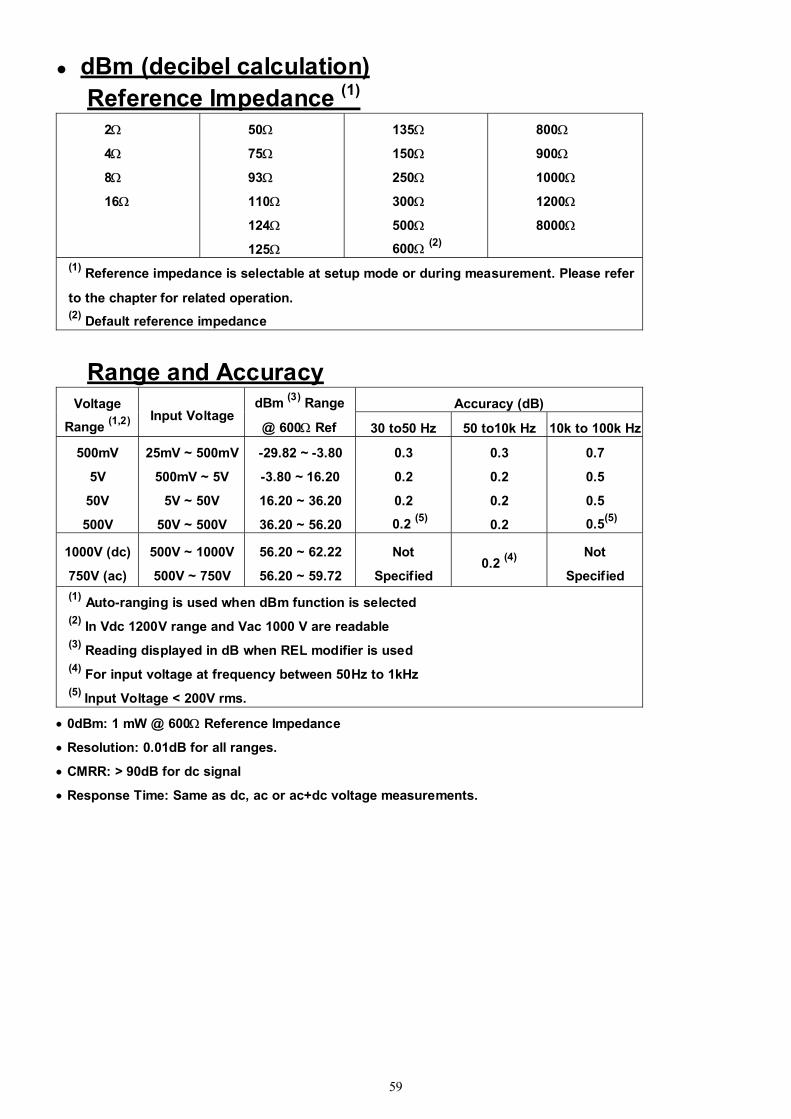
59
dBm (decibel calculation) Reference Impedance (1)
2Ω
4Ω
8Ω
16Ω
50Ω 75Ω
93Ω
110Ω
124Ω 125Ω
135Ω 150Ω
250Ω
300Ω
500Ω 600Ω (2)
800Ω
900Ω
1000Ω 1200Ω
8000Ω
(1) Reference impedance is selectable at setup mode or during measurement. Please refer
to the chapter for related operation.
(2) Default reference impedance
Range and Accuracy Accuracy (dB) Voltage
Range (1,2) Input Voltage
dBm (3) Range
@ 600Ω Ref 30 to50 Hz 50 to10k Hz 10k to 100k Hz
500mV
5V
50V
500V
25mV ~ 500mV
500mV ~ 5V
5V ~ 50V
50V ~ 500V
-29.82 ~ -3.80
-3.80 ~ 16.20
16.20 ~ 36.20
36.20 ~ 56.20
0.3
0.2
0.2
0.2 (5)
0.3
0.2
0.2
0.2
0.7
0.5
0.5
0.5(5)
1000V (dc)
750V (ac)
500V ~ 1000V
500V ~ 750V
56.20 ~ 62.22
56.20 ~ 59.72
Not
Specified 0.2 (4)
Not
Specified (1) Auto-ranging is used when dBm function is selected (2) In Vdc 1200V range and Vac 1000 V are readable (3) Reading displayed in dB when REL modifier is used (4) For input voltage at frequency between 50Hz to 1kHz (5) Input Voltage < 200V rms.
• 0dBm: 1 mW @ 600Ω Reference Impedance
• Resolution: 0.01dB for all ranges.
• CMRR: > 90dB for dc signal
• Response Time: Same as dc, ac or ac+dc voltage measurements.
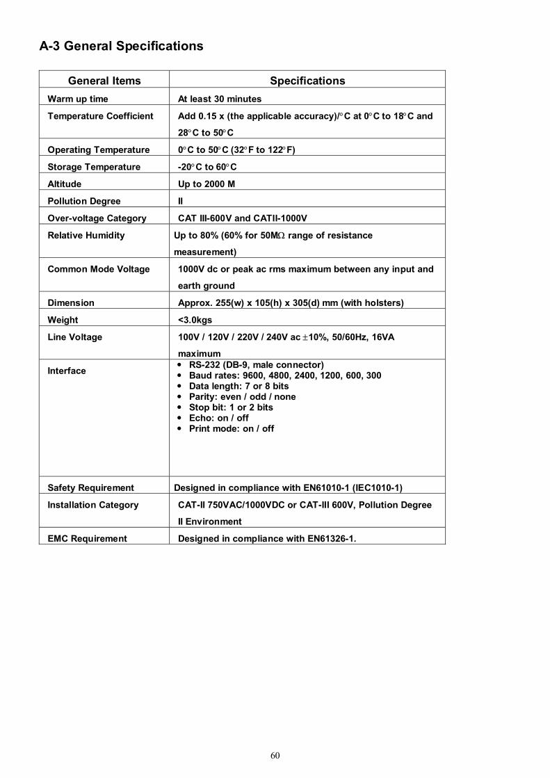
60
A-3 General Specifications
General Items Specifications Warm up time At least 30 minutes Temperature Coefficient
Add 0.15 x (the applicable accuracy)/°C at 0°C to 18°C and
28°C to 50°C
Operating Temperature 0°C to 50°C (32°F to 122°F)
Storage Temperature -20°C to 60°C
Altitude Up to 2000 M
Pollution Degree II
Over-voltage Category CAT III-600V and CATII-1000V
Relative Humidity Up to 80% (60% for 50MΩ range of resistance
measurement)
Common Mode Voltage
1000V dc or peak ac rms maximum between any input and
earth ground
Dimension Approx. 255(w) x 105(h) x 305(d) mm (with holsters)
Weight <3.0kgs
Line Voltage 100V / 120V / 220V / 240V ac ±10%, 50/60Hz, 16VA
maximum
Interface
RS-232 (DB-9, male connector) Baud rates: 9600, 4800, 2400, 1200, 600, 300 Data length: 7 or 8 bits Parity: even / odd / none Stop bit: 1 or 2 bits Echo: on / off Print mode: on / off
Safety Requirement Designed in compliance with EN61010-1 (IEC1010-1)
Installation Category
CAT-II 750VAC/1000VDC or CAT-III 600V, Pollution Degree
II Environment
EMC Requirement Designed in compliance with EN61326-1.

61
Appendix B Maintenance
B-1 Introduction Appendix B describes the basic maintenance procedures to this Multi-meter.
B-2 Cleaning the Meter
Before cleaning this meter, make sure the power is switched in OFF position and the power cord is disconnected from the AC outlet. To clean the meter, wipe the dirty parts with gauze or soft cloth soaked with diluted neutral detergent. Do not get too wet to prevent the detergent from penetrating into inside parts and causing damages. After cleaning, make sure the instrument is dried completely before using.
B-3 Configure the Line Voltage
Extract the fuse drawer from the AC socket with the aid of a screwdriver to move the fuse holder with the voltage selector from the fuse holder.
Pull out the fuse link from the fuse holder with the voltage selector. Replace a new fuse with a rated voltage with specific required line voltage. Select the voltage according to users local line voltage. If the line voltage used is 230V, be sure to switch the line voltage selection to 240V.
WARNING! To avoid electrical shock or damaging the meter, never get water inside the case.
Caution! Before setting the line voltage selector, the main power should be turned off and remove Power cord from the meter. This meter operates on a 100V, 120V, 220V or 240V AC, 50/60Hz line voltage source.
Be sure the line voltage is indicated to your need.

www.icel-manaus.com.br [email protected]