Manual CPE QUICK INSTALL GUIDE
18
IEEE 802.11a/n Wireless Outdoor CPE Quick Installation Guide V 2.0 July 2010
Transcript of Manual CPE QUICK INSTALL GUIDE
IEEE 802.11a/n Wireless Outdoor CPE
Quick Installation Guide
V 2.0 July 2010
Copyright
Copyright © 2010 all rights reserved. No part of this publication may be reproduced, adapted,
stored in a retrieval system, translated into any language, or transmitted in any form or by any
means without the written permission of the supplier.
About the Quick Installation Guide
This Quick Installation Guide is intended to guide professional installer to install the IEEE
802.11a/n Wireless Outdoor CP. It covers procedures to assist you in avoiding unforeseen
problems.
Conventions
This sign indicates a warning or caution that you have to abide.
This sign indicates an important note that you must pay attention to.
Note:
Warning:

Chapter 1 Introduction Page 3
Chapter 1 Introduction
Introduction
The IEEE 802.11a/n Wireless Outdoor CPE is a multi-mode last-mile broadband solution for
customers like wireless ISP (WISPs) and system integrators. By the nature of complying with
the IEEE802.11n standard and featuring high power output, the IEEE 802.11a/n Wireless CPE
supports higher bandwidth of up to 300Mbps with longer range for outdoor applications.
The IEEE 802.11a/n Wireless Outdoor CPE can be used as the access point, the customer
premises equipment (CPE), the WDS or the AP Repeater. While being as the access point, it
can be deployed outdoors to provide outdoor wireless internet service. In the other way to be
as the outdoor CPE, it can receive wireless signal over the last mile, helping WISPs deliver
internet service to the new residential and the business customer where wired broadband
internet service, such as cable and DSL, can not serve in. In addition, the easy-to-install
Wireless Outdoor CPE covers 5GHz bands, which features outstanding throughput
performance and a cost-effective design that allows users to have the reliable outdoor
equipment at the affordable price.
Chapter 2 Preparation before Installation Page 4
Chapter 2 Preparation before Installation
This chapter describes safety precautions and product information you have to know. Please
check this chapter before installing the CPE.
Professional Installation Required
Please seek assistance from a professional installer who is well trained in the RF installation
and knowledgeable in the local regulations.
Safety Precautions
To keep you safe and install the hardware properly, please read and follow these safety
precautions.
1. If you are installing the IEEE 802.11a/n Wireless Outdoor CPE for the first time, for your
safety as well as others’, please seek assistance from a professional installer who has
received safety training on the hazards involved.
2. Keep safety as well as performance in mind when selecting your installation site,
especially where there are electric power and phone lines.
3. When installing the CPE, please note the following things:
♦ Do not use a metal ladder;
♦ Do not work on a wet or windy day;
♦ Wear shoes with rubber soles and heels, rubber gloves, long sleeved shirt or jacket.
4. When the system is operational, avoid standing directly in front of it. Strong RF fields are
present when the transmitter is on.
Chapter 2 Preparation before Installation Page 5
Installation Precautions
To keep the CPE well while you are installing it, please read and follow these installation
precautions.
1. Users MUST use a proper and well-installed surge arrestor with the IEEE 802.11a/n
Wireless Outdoor CPE; otherwise, a random lightening could easily cause fatal damage to
the unit. EMD (Lightning) DAMAGE IS NOT COVERED UNDER WARRNTY.
2. Users MUST use the “Power cord & PoE Injector” shipped in the box with the CPE. Use of
other options will cause damage to the unit.
3. Users MUST power off the CPE first before connecting the external antenna to it. Do not
switch from built-in antenna to the external antenna from WEB management without
physically attaching the external antenna onto the CPE; otherwise, damage might be
caused to the unit itself.
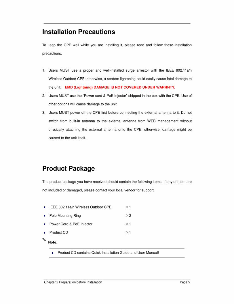
Product Package
The product package you have received should contain the following items. If any of them are
not included or damaged, please contact your local vendor for support.
IEEE 802.11a/n Wireless Outdoor CPE ×1
Pole Mounting Ring ×2
Power Cord & PoE Injector ×1
Product CD ×1
Product CD contains Quick Installation Guide and User Manual!
Note:

Chapter 2 Preparation before Installation Page 6
Pole Mounting Ring
- Power cord & PoE Injector
Users MUST use the “Power cord & PoE Injector” shipped in the box with the CPE.
Use of other options will cause damage to the unit.
Warning:

Chapter 3 System Installation Page 7
Chapter 3 System Installation
Connect up
1. The bottom of IEEE 802.11a/n wireless outdoor CPE is a movable cover. Loosen the
screw with a Philips screwdriver. Grab the cover and pull it back harder to take it out as
the figure shown below.
2. Plug a standard Ethernet cable into the RJ45 port labeled “LAN 1”. Do not plug the
cable into the RJ45 port labeled “LAN 2”.
Chapter 3 System Installation Page 8
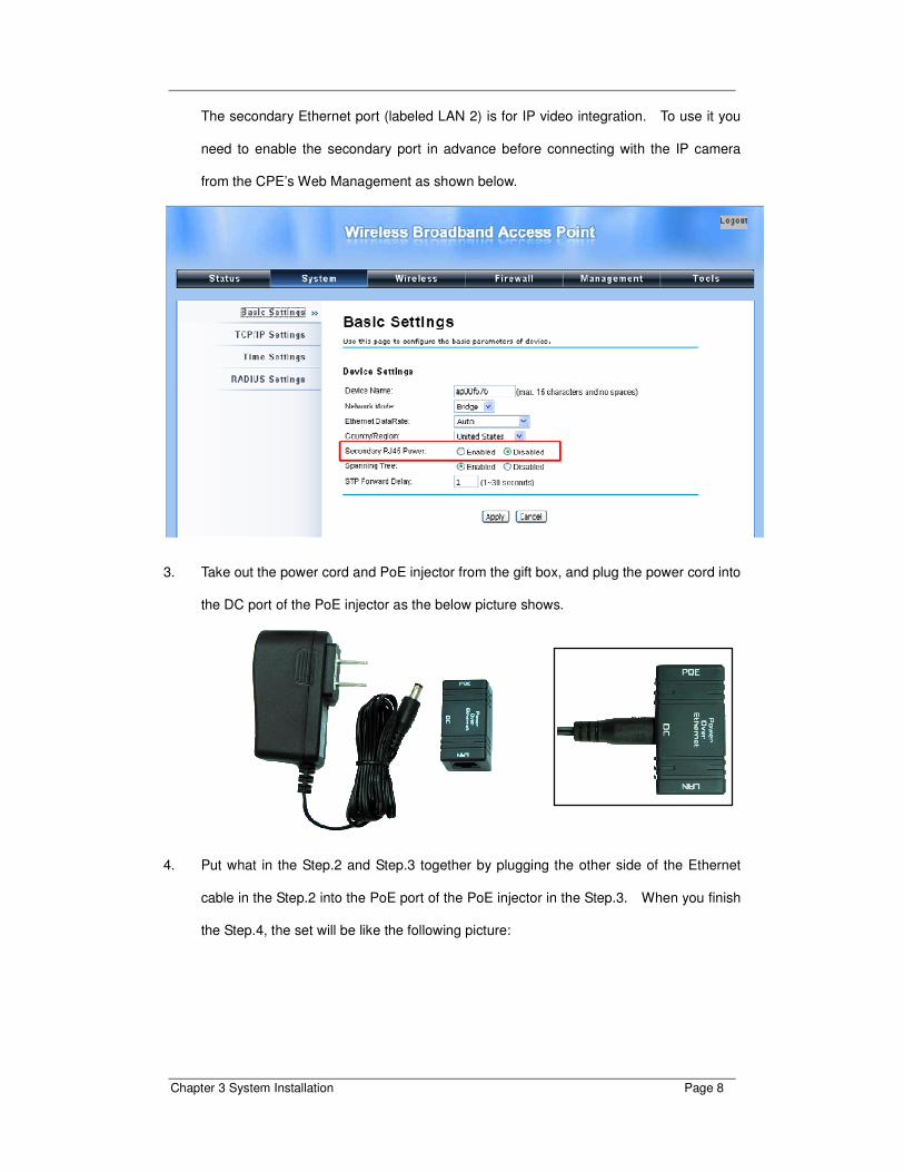
The secondary Ethernet port (labeled LAN 2) is for IP video integration. To use it you
need to enable the secondary port in advance before connecting with the IP camera
from the CPE’s Web Management as shown below.
3. Take out the power cord and PoE injector from the gift box, and plug the power cord into
the DC port of the PoE injector as the below picture shows.
4. Put what in the Step.2 and Step.3 together by plugging the other side of the Ethernet
cable in the Step.2 into the PoE port of the PoE injector in the Step.3. When you finish
the Step.4, the set will be like the following picture:

Chapter 3 System Installation Page 9
5. Press the black PWR button beside the LAN 1 Ethernet port.
6. Attach and fasten the removable cover to the bottom of the unit with the screw.
7. Power on the IEEE 802.11a/n Wireless Outdoor CPE by plugging the power adapter to
the power socket.
Chapter 3 System Installation Page 10
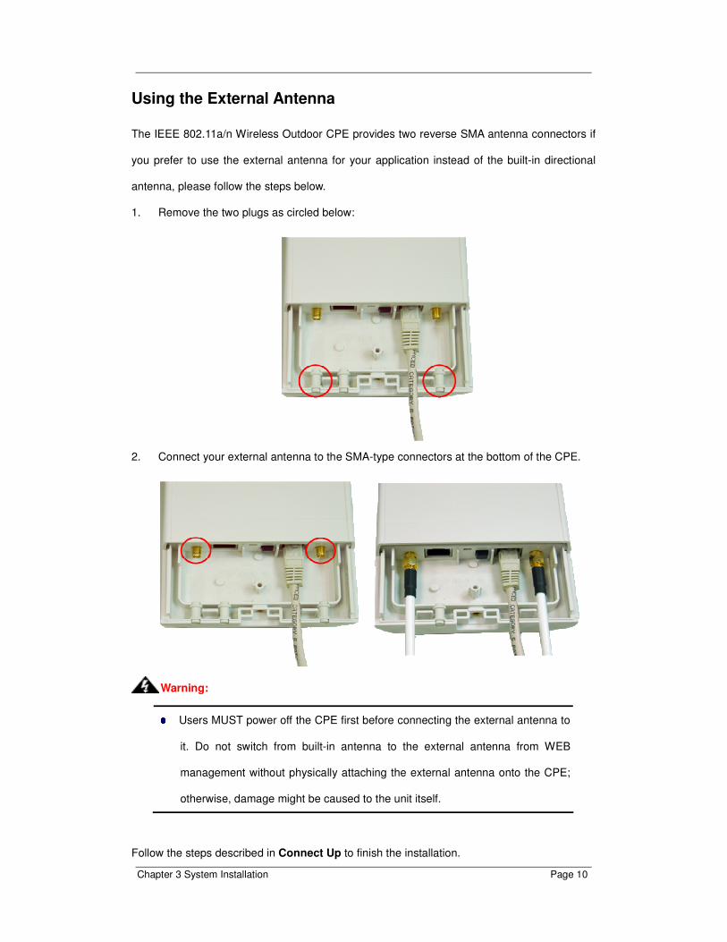
Using the External Antenna
The IEEE 802.11a/n Wireless Outdoor CPE provides two reverse SMA antenna connectors if
you prefer to use the external antenna for your application instead of the built-in directional
antenna, please follow the steps below.
1. Remove the two plugs as circled below:
2. Connect your external antenna to the SMA-type connectors at the bottom of the CPE.
Users MUST power off the CPE first before connecting the external antenna to
it. Do not switch from built-in antenna to the external antenna from WEB
management without physically attaching the external antenna onto the CPE;
otherwise, damage might be caused to the unit itself.
Follow the steps described in Connect Up to finish the installation.
Warning:

Chapter 3 System Installation Page 11
Pole Mounting
1. Turn the CPE over. Put the pole mounting rings through the middle hole of it. Note that
you should unlock the pole mounting ring with a screw driver before putting it through the
CPE as the following right picture shows.
2. Mount the IEEE 802.11a/n Wireless Outdoor CPE steadily to the pole by locking the pole
mounting ring tightly.
Now you have completed the hardware installation of the IEEE 802.11a/n Wireless Outdoor
CPE.
Chapter 3 System Installation Page 12
Chapter 4 Configuration
Connect the IEEE 802.11a/n Wireless Outdoor CPE with your PC by an Ethernet cable
plugging in LAN port of PoE injector in one side and in LAN port of PC in the other side.
Power on the CPE by PoE from PoE injector.
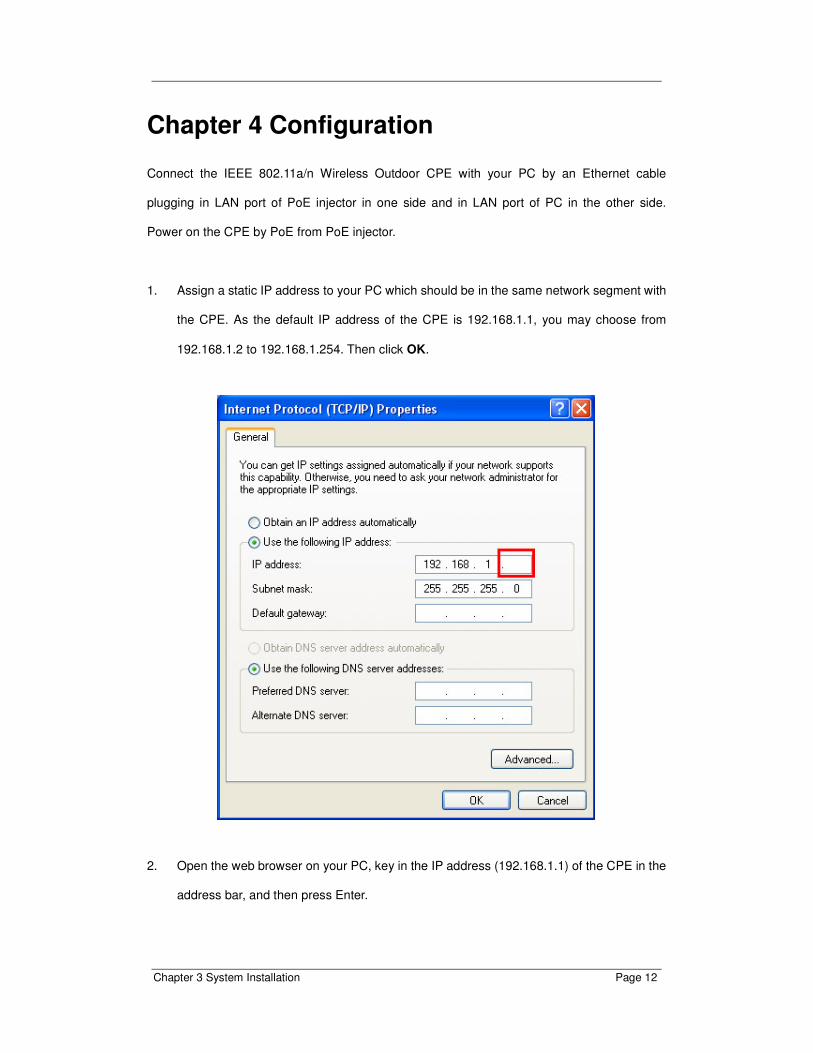
1. Assign a static IP address to your PC which should be in the same network segment with
the CPE. As the default IP address of the CPE is 192.168.1.1, you may choose from
192.168.1.2 to 192.168.1.254. Then click OK.
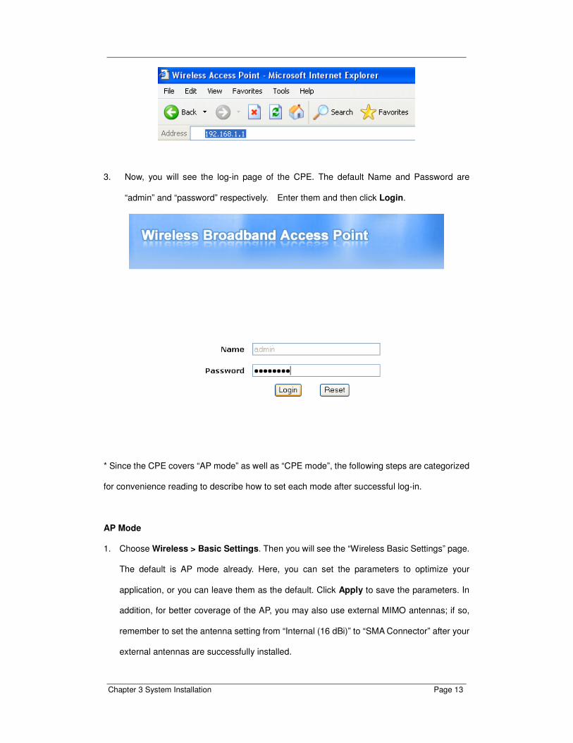
2. Open the web browser on your PC, key in the IP address (192.168.1.1) of the CPE in the
address bar, and then press Enter.
Chapter 3 System Installation Page 13
3. Now, you will see the log-in page of the CPE. The default Name and Password are
“admin” and “password” respectively. Enter them and then click Login.
* Since the CPE covers “AP mode” as well as “CPE mode”, the following steps are categorized
for convenience reading to describe how to set each mode after successful log-in.
AP Mode
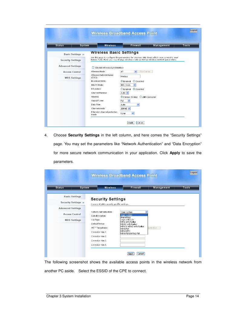
1. Choose Wireless > Basic Settings. Then you will see the “Wireless Basic Settings” page.
The default is AP mode already. Here, you can set the parameters to optimize your
application, or you can leave them as the default. Click Apply to save the parameters. In
addition, for better coverage of the AP, you may also use external MIMO antennas; if so,
remember to set the antenna setting from “Internal (16 dBi)” to “SMA Connector” after your
external antennas are successfully installed.
Chapter 3 System Installation Page 14
4. Choose Security Settings in the left column, and here comes the “Security Settings”
page. You may set the parameters like “Network Authentication” and “Data Encryption”
for more secure network communication in your application. Click Apply to save the
parameters.
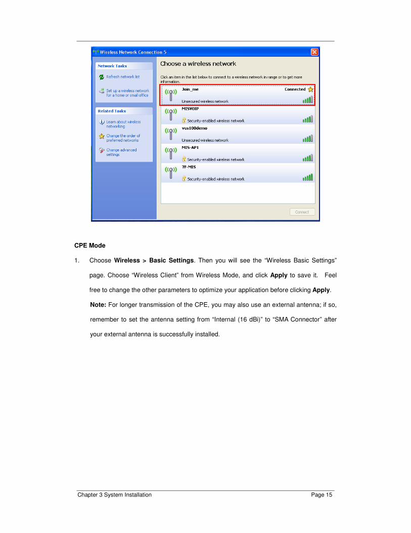
The following screenshot shows the available access points in the wireless network from
another PC aside. Select the ESSID of the CPE to connect.
Chapter 3 System Installation Page 15
CPE Mode
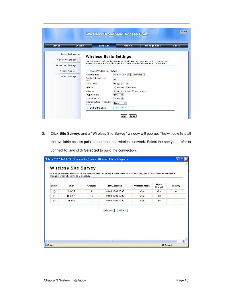
1. Choose Wireless > Basic Settings. Then you will see the “Wireless Basic Settings”
page. Choose “Wireless Client” from Wireless Mode, and click Apply to save it. Feel
free to change the other parameters to optimize your application before clicking Apply.
Note: For longer transmission of the CPE, you may also use an external antenna; if so,
remember to set the antenna setting from “Internal (16 dBi)” to “SMA Connector” after
your external antenna is successfully installed.
Chapter 3 System Installation Page 16
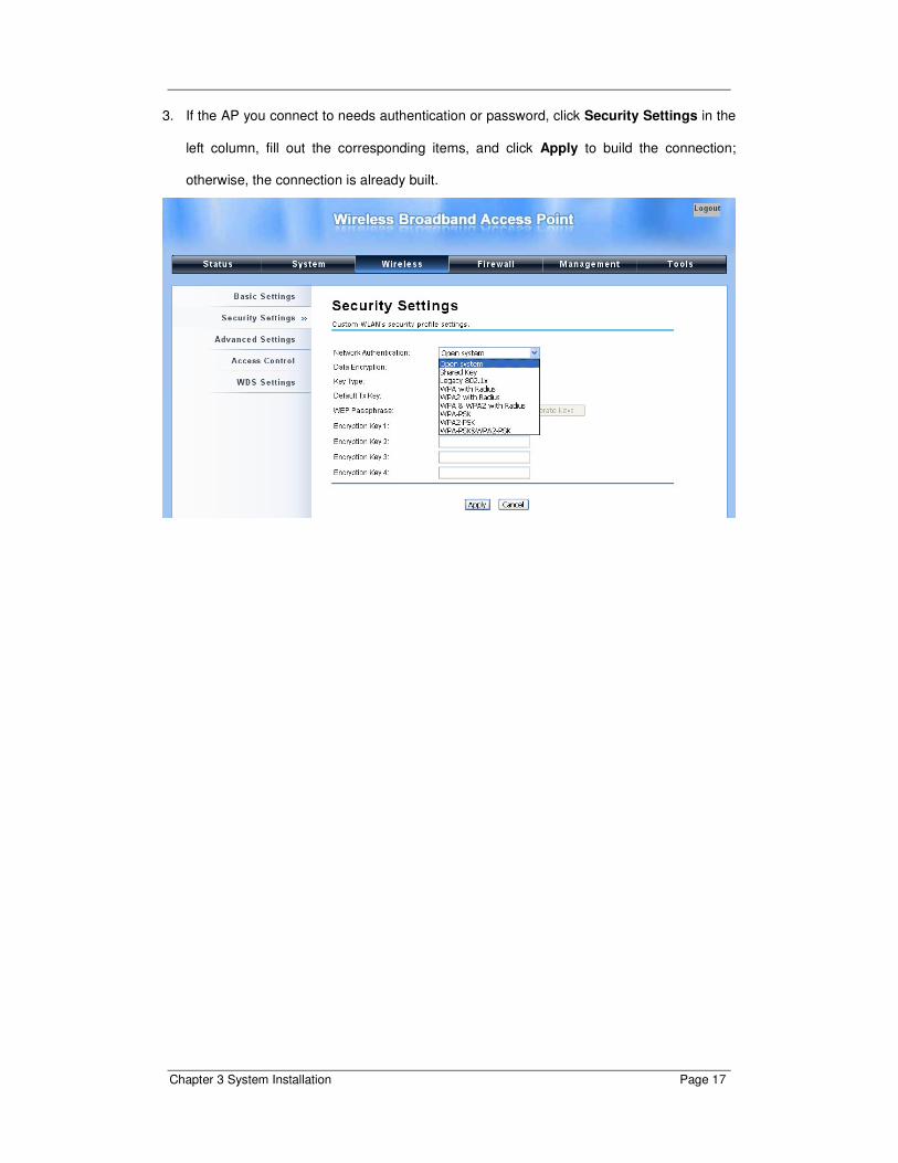
2. Click Site Survey, and a “Wireless Site Survey” window will pop up. The window lists all
the available access points / routers in the wireless network. Select the one you prefer to
connect to, and click Selected to build the connection.
Chapter 3 System Installation Page 17
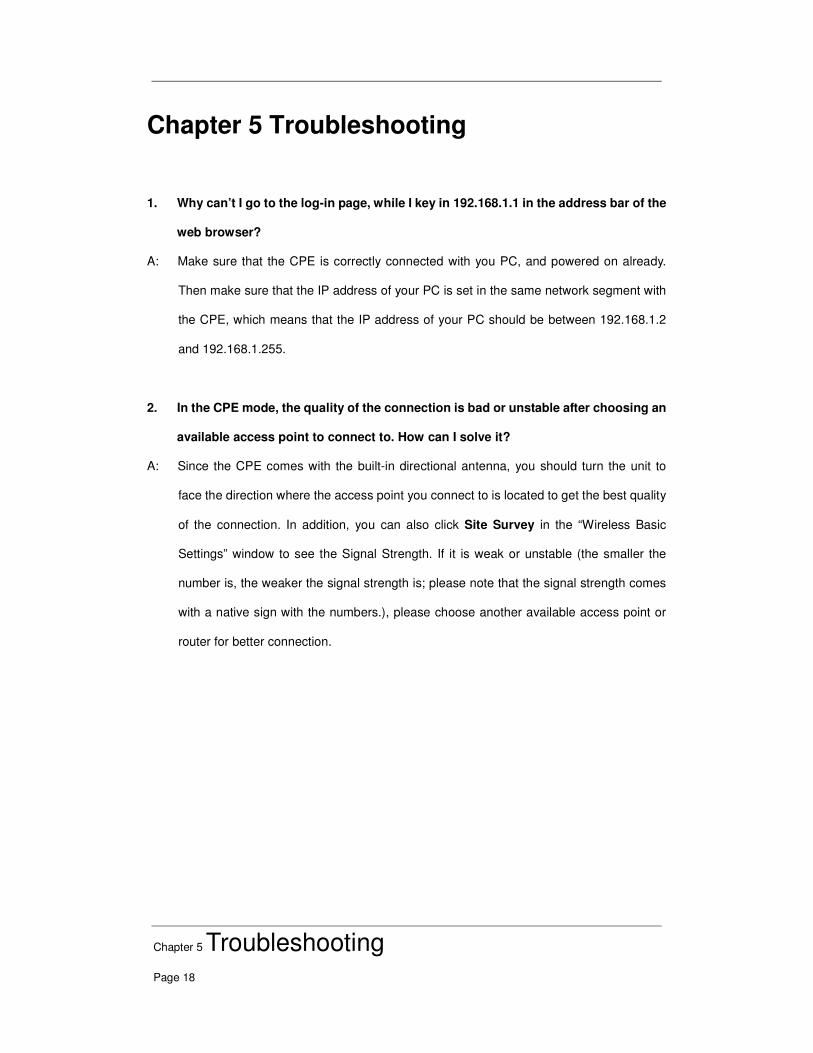
3. If the AP you connect to needs authentication or password, click Security Settings in the
left column, fill out the corresponding items, and click Apply to build the connection;
otherwise, the connection is already built.
Chapter 5 Troubleshooting
Page 18
Chapter 5 Troubleshooting
1. Why can’t I go to the log-in page, while I key in 192.168.1.1 in the address bar of the
web browser?
A: Make sure that the CPE is correctly connected with you PC, and powered on already.
Then make sure that the IP address of your PC is set in the same network segment with
the CPE, which means that the IP address of your PC should be between 192.168.1.2
and 192.168.1.255.
2. In the CPE mode, the quality of the connection is bad or unstable after choosing an
available access point to connect to. How can I solve it?
A: Since the CPE comes with the built-in directional antenna, you should turn the unit to
face the direction where the access point you connect to is located to get the best quality
of the connection. In addition, you can also click Site Survey in the “Wireless Basic
Settings” window to see the Signal Strength. If it is weak or unstable (the smaller the
number is, the weaker the signal strength is; please note that the signal strength comes
with a native sign with the numbers.), please choose another available access point or
router for better connection.