
Manual Cople Devicenet
200
Modular I/O System DeviceNet 750-306, 750-806 Manual Technical Description, Installation and Configuration Version 1.0.0
Transcript of Manual Cople Devicenet
Modular I/O System
DeviceNet
750-306, 750-806
Manual
Technical Description, Installation and Configuration
Version 1.0.0
ii • General
WAGO-I/O-SYSTEM 750 DeviceNet
Copyright © 2007 by WAGO Kontakttechnik GmbH & Co. KG All rights reserved.
WAGO Kontakttechnik GmbH & Co. KG Hansastraße 27 D-32423 Minden
Phone: +49 (0) 571/8 87 – 0 Fax: +49 (0) 571/8 87 – 1 69
E-Mail: [email protected]
Web: http://www.wago.com
Technical Support Phone: +49 (0) 571/8 87 – 5 55 Fax: +49 (0) 571/8 87 – 85 55
E-Mail: [email protected]
Every conceivable measure has been taken to ensure the correctness and com-pleteness of this documentation. However, as errors can never be fully ex-cluded we would appreciate any information or ideas at any time.
E-Mail: [email protected]
We wish to point out that the software and hardware terms as well as the trademarks of companies used and/or mentioned in the present manual are generally trademark or patent protected.

Table of Contents • iii
WAGO-I/O-SYSTEM 750 DeviceNet
TABLE OF CONTENTS 1 Important Notes .......................................................................................... 7 1.1 Legal Principles........................................................................................ 7 1.1.1 Copyright ............................................................................................. 7 1.1.2 Personnel Qualification ....................................................................... 7 1.1.3 Conforming Use of Series 750 ............................................................ 8 1.1.4 Technical Condition of the Devices .................................................... 8 1.2 Standards and Regulations for Operating the 750 Series ......................... 8 1.3 Symbols .................................................................................................... 9 1.4 Safety Information.................................................................................. 10 1.5 Font Conventions ................................................................................... 11 1.6 Number Notation.................................................................................... 11 1.7 Scope ...................................................................................................... 12 1.8 Abbreviation........................................................................................... 12
2 The WAGO-I/O-SYSTEM 750 ................................................................ 13 2.1 System Description................................................................................. 13 2.2 Technical Data........................................................................................ 14 2.3 Manufacturing Number .......................................................................... 20 2.4 Component Update................................................................................. 21 2.5 Storage, Assembly and Transport .......................................................... 21 2.6 Mechanical Setup ................................................................................... 22 2.6.1 Installation Position ........................................................................... 22 2.6.2 Total Expansion................................................................................. 22 2.6.3 Assembly onto Carrier Rail ............................................................... 23 2.6.3.1 Carrier rail properties.................................................................... 23 2.6.3.2 WAGO DIN Rail .......................................................................... 24 2.6.4 Spacing .............................................................................................. 24 2.6.5 Plugging and Removal of the Components ....................................... 25 2.6.6 Assembly Sequence ........................................................................... 26 2.6.7 Internal Bus/Data Contacts................................................................ 27 2.6.8 Power Contacts .................................................................................. 28 2.6.9 Wire connection................................................................................. 29 2.7 Power Supply ......................................................................................... 30 2.7.1 Isolation ............................................................................................. 30 2.7.2 System Supply ................................................................................... 31 2.7.2.1 Connection .................................................................................... 31 2.7.2.2 Alignment ..................................................................................... 32 2.7.3 Field Supply....................................................................................... 34 2.7.3.1 Connection .................................................................................... 34 2.7.3.2 Fusing............................................................................................ 35 2.7.4 Supplementary power supply regulations.......................................... 38 2.7.5 Supply example ................................................................................. 39 2.7.6 Power Supply Unit............................................................................. 40 2.8 Grounding............................................................................................... 41 2.8.1 Grounding the DIN Rail .................................................................... 41 2.8.1.1 Framework Assembly ................................................................... 41 2.8.1.2 Insulated Assembly....................................................................... 41

iv • Table of Contents
WAGO-I/O-SYSTEM 750 DeviceNet
2.8.2 Grounding Function........................................................................... 42 2.8.3 Grounding Protection ........................................................................ 43 2.9 Shielding (Screening) ............................................................................. 44 2.9.1 General............................................................................................... 44 2.9.2 Bus Conductors.................................................................................. 44 2.9.3 Signal Conductors.............................................................................. 44 2.9.4 WAGO Shield (Screen) Connecting System..................................... 45 2.10 Assembly Guidelines/Standards............................................................. 45
3 Fieldbus Coupler/Controller .................................................................... 46 3.1 Fieldbus Coupler 750-306 ...................................................................... 46 3.1.1 Description......................................................................................... 46 3.1.2 Hardware............................................................................................ 47 3.1.2.1 View.............................................................................................. 47 3.1.2.2 Device Supply............................................................................... 48 3.1.2.3 Fieldbus Connection ..................................................................... 49 3.1.2.4 Display Elements .......................................................................... 50 3.1.2.5 Configuration Interface................................................................. 51 3.1.2.6 Hardware Address (MAC ID)....................................................... 51 3.1.2.7 Setting the Baud Rate.................................................................... 52 3.1.3 Operating System............................................................................... 52 3.1.4 Process Image .................................................................................... 53 3.1.5 Data Exchange ................................................................................... 54 3.1.5.1 Communication Interfaces ............................................................ 55 3.1.5.2 Memory Areas .............................................................................. 55 3.1.5.3 Addressing .................................................................................... 56 3.1.6 Configuration Software ..................................................................... 58 3.1.7 Starting up DeviceNet Fieldbus Nodes ............................................. 58 3.1.7.1 Connecting the PC and Fieldbus Node ......................................... 59 3.1.7.2 Setting the MAC ID and Baud Rate ............................................. 59 3.1.7.3 Configuration with Static Assembly............................................. 60 3.1.8 LED Display ...................................................................................... 64 3.1.8.1 Node status – Blink code from the 'I/O' LED ............................... 65 3.1.8.2 Supply voltage status .................................................................... 72 3.1.9 Technical Data ................................................................................... 73 3.2 Fieldbus Controller 750-806 .................................................................. 74 3.2.1 Description......................................................................................... 74 3.2.2 Hardware............................................................................................ 75 3.2.2.1 View.............................................................................................. 75 3.2.2.2 Device Supply............................................................................... 76 3.2.2.3 Fieldbus Connection ..................................................................... 77 3.2.2.4 Display Elements .......................................................................... 78 3.2.2.5 Configuration and Programming Interface ................................... 79 3.2.2.6 Operating Mode Switch ................................................................ 79 3.2.2.7 Hardware Address (MAC ID)....................................................... 80 3.2.2.8 Setting the Baud Rate.................................................................... 81 3.2.3 Operating System............................................................................... 82 3.2.3.1 Start-up.......................................................................................... 82 3.2.3.2 PLC Cycle ..................................................................................... 82 3.2.4 Process Image .................................................................................... 84
Table of Contents • v
WAGO-I/O-SYSTEM 750 DeviceNet
3.2.5 Data Exchange................................................................................... 85 3.2.5.1 Communication Interfaces ............................................................ 86 3.2.5.2 Memory Areas .............................................................................. 86 3.2.5.3 Addressing .................................................................................... 89 3.2.6 Programming the PFC with WAGO-I/O-PRO 32 ............................. 93 3.2.6.1 WAGO-I/O-PRO 32 Library Elements ........................................ 93 3.2.6.2 IEC 61131-3 Program Transfer .................................................... 94 3.2.7 Special DeviceNet Features of the Controller ................................... 97 3.2.7.1 Connection via the UCMM port ................................................... 97 3.2.7.2 Offline Connection Set ................................................................. 97 3.2.7.3 DeviceNet Shutdown .................................................................... 97 3.2.7.4 Dynamic Assembly....................................................................... 97 3.2.7.5 Change MAC ID by SW ............................................................... 98 3.2.7.6 Heartbeat ....................................................................................... 98 3.2.7.7 Bit-Strobe...................................................................................... 98 3.2.8 Configuration Software ..................................................................... 99 3.2.9 Starting-up DeviceNet Fieldbus Nodes ............................................. 99 3.2.9.1 Connecting the PC and Fieldbus Node ......................................... 99 3.2.9.2 Setting the MAC ID and Baud Rate ............................................. 99 3.2.9.3 Configuration with Static and Dynamic Assembly .................... 100 3.2.10 LED Display .................................................................................... 111 3.2.10.1 Node status – Blink code from the 'I/O' LED ............................. 112 3.2.10.2 Supply voltage status .................................................................. 119 3.2.11 Technical Data ................................................................................. 120
4 DeviceNet ................................................................................................. 122 4.1 Description ........................................................................................... 122 4.2 Network Architecture ........................................................................... 123 4.2.1 Transmission Media ........................................................................ 123 4.2.1.1 Type of Cable.............................................................................. 123 4.2.1.2 Cable Types ................................................................................ 123 4.2.1.3 Maximum Bus Length ................................................................ 124 4.2.2 Cabling............................................................................................. 124 4.2.3 Network Topology........................................................................... 126 4.2.4 Network Grounding......................................................................... 127 4.2.5 Interface Modules ............................................................................ 127 4.3 Network Communication ..................................................................... 128 4.3.1 Objects, Classes, Instances and Attributes ...................................... 128 4.4 Module Characteristics......................................................................... 129 4.4.1 Communication Model .................................................................... 129 4.4.1.1 Message Groups.......................................................................... 129 4.4.1.2 Message Types............................................................................ 129 4.4.2 I/O Messaging Connections............................................................. 130 4.5 Process data and Diagnostic Status ...................................................... 130 4.5.1 Process Image .................................................................................. 130 4.5.1.1 Assembly Instances..................................................................... 131 4.6 Configuration / Parametering with the Object Model .......................... 133 4.6.1 EDS Files ......................................................................................... 133 4.6.2 Object Model ................................................................................... 134 4.6.2.1 Object Model for Coupler 750-306 and Controller 750-806...... 135

vi • Table of Contents
WAGO-I/O-SYSTEM 750 DeviceNet
4.6.2.2 Supplement to the Object Model for Controller 750-806........... 151
5 I/O Modules ............................................................................................. 158 5.1 Overview .............................................................................................. 158 5.1.1 Digital Input Modules...................................................................... 158 5.1.2 Digital Output Modules ................................................................... 160 5.1.3 Analog Intput Modules .................................................................... 161 5.1.4 Analog Output Modules .................................................................. 162 5.1.5 Special Modules .............................................................................. 163 5.1.6 System Modules............................................................................... 164 5.2 Process Data Architecture for DeviceNet ............................................ 165 5.2.1 Digital Input Modules...................................................................... 165 5.2.2 Digital Output Modules ................................................................... 167 5.2.3 Analog Input Modules ..................................................................... 171 5.2.4 Analog Output Modules .................................................................. 173 5.2.5 Specialty Modules ........................................................................... 174 5.2.6 System Modules............................................................................... 186
6 Use in Hazardous Environments ........................................................... 187 6.1 Foreword .............................................................................................. 187 6.2 Protective measures .............................................................................. 187 6.3 Classification meeting CENELEC and IEC......................................... 187 6.3.1 Divisions .......................................................................................... 187 6.3.2 Explosion protection group ............................................................. 188 6.3.3 Unit categories ................................................................................. 189 6.3.4 Temperature classes......................................................................... 189 6.3.5 Types of ignition protection ............................................................ 190 6.4 Classifications meeting the NEC 500................................................... 191 6.4.1 Divisions .......................................................................................... 191 6.4.2 Explosion protection groups............................................................ 191 6.4.3 Temperature classes......................................................................... 192 6.5 Identification ........................................................................................ 193 6.5.1 For Europe ....................................................................................... 193 6.5.2 For America ..................................................................................... 194 6.6 Installation regulations ......................................................................... 195
7 Glossary.................................................................................................... 197
8 Literature List ......................................................................................... 198
9 Index ......................................................................................................... 199

Important Notes • 7 Legal Principles
WAGO-I/O-SYSTEM 750 DeviceNet
1 Important Notes This section provides only a summary of the most important safety require-ments and notes which will be mentioned in the individual sections. To protect your health and prevent damage to the devices, it is essential to read and care-fully follow the safety guidelines.
1.1 Legal Principles
1.1.1 Copyright
This manual including all figures and illustrations contained therein is subject to copyright. Any use of this manual which infringes the copyright provisions stipulated herein, is not permitted. Reproduction, translation and electronic and phototechnical archiving and amendments require the written consent of WAGO Kontakttechnik GmbH & Co. KG, Minden. Non-observance will en-tail the right of claims for damages.
WAGO Kontakttechnik GmbH & Co. KG reserves the right of changes serv-ing technical progress. All rights developing from the issue of a patent or the legal protection of util-ity patents are reserved to WAGO Kontakttechnik GmbH & Co. KG. Third-party products are always indicated without any notes concerning patent rights. Thus, the existence of such rights must not be excluded.
1.1.2 Personnel Qualification
The use of the product described in this manual requires special qualifications, as shown in the following table:
Activity Electrical specialist Instructed person-nel*)
Specialists**) having qualifications in PLC programming
Assembly X X
Commissioning X X
Programming X
Maintenance X X
Troubleshooting X
Disassembly X X
*) Instructed persons have been trained by qualified personnel or electrical specialists.
**) A specialist is someone who, through technical training, knowledge and experience, demonstrates the ability to meet the relevant specifications and identify potential dangers in the mentioned field of activity.
All personnel must be familiar with the applicable standards. WAGO Kontakttechnik GmbH & Co. KG declines any liability resulting from
8 • Important Notes Standards and Regulations for Operating the 750 Series
WAGO-I/O-SYSTEM 750 DeviceNet
improper action and damage to WAGO products and third party products due to non-observance of the information contained in this manual.
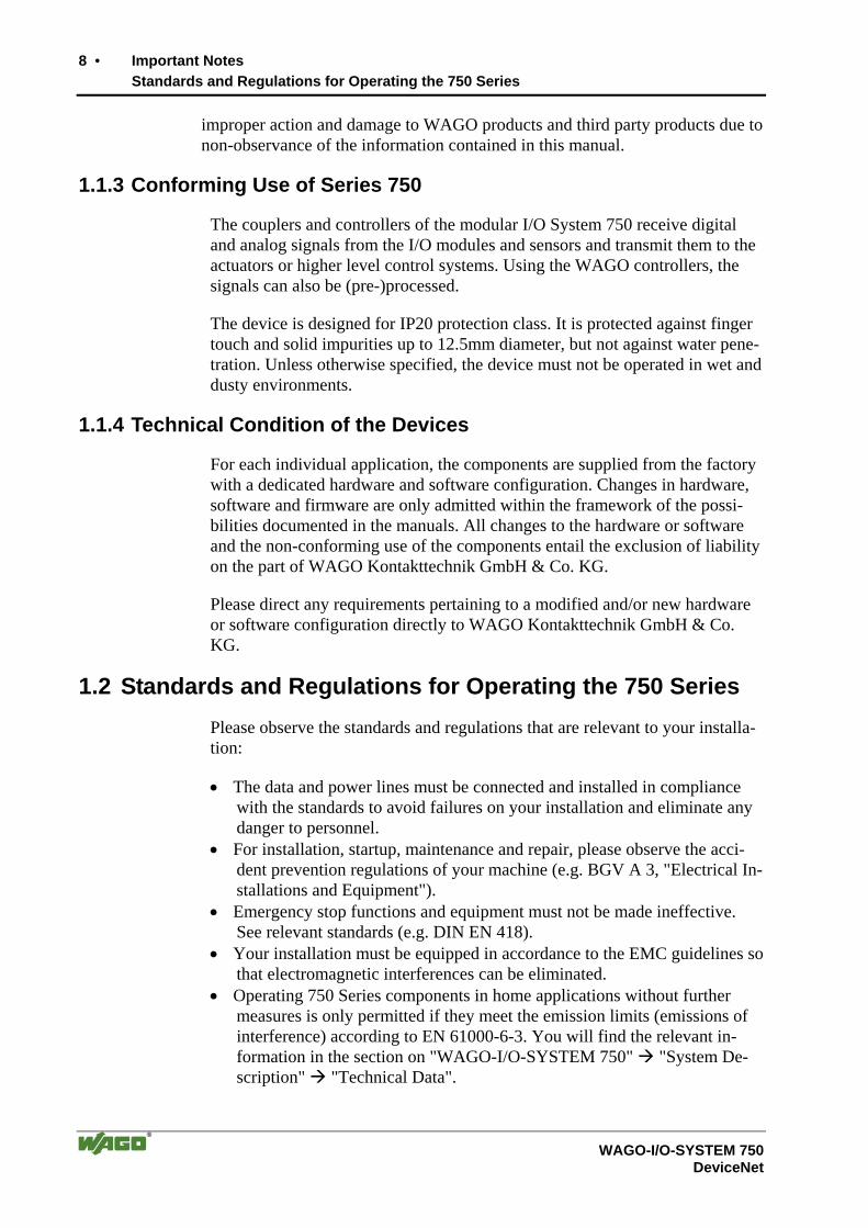
1.1.3 Conforming Use of Series 750
The couplers and controllers of the modular I/O System 750 receive digital and analog signals from the I/O modules and sensors and transmit them to the actuators or higher level control systems. Using the WAGO controllers, the signals can also be (pre-)processed.
The device is designed for IP20 protection class. It is protected against finger touch and solid impurities up to 12.5mm diameter, but not against water pene-tration. Unless otherwise specified, the device must not be operated in wet and dusty environments.
1.1.4 Technical Condition of the Devices
For each individual application, the components are supplied from the factory with a dedicated hardware and software configuration. Changes in hardware, software and firmware are only admitted within the framework of the possi-bilities documented in the manuals. All changes to the hardware or software and the non-conforming use of the components entail the exclusion of liability on the part of WAGO Kontakttechnik GmbH & Co. KG.
Please direct any requirements pertaining to a modified and/or new hardware or software configuration directly to WAGO Kontakttechnik GmbH & Co. KG.
1.2 Standards and Regulations for Operating the 750 Series Please observe the standards and regulations that are relevant to your installa-tion:
• The data and power lines must be connected and installed in compliance with the standards to avoid failures on your installation and eliminate any danger to personnel.
• For installation, startup, maintenance and repair, please observe the acci-dent prevention regulations of your machine (e.g. BGV A 3, "Electrical In-stallations and Equipment").
• Emergency stop functions and equipment must not be made ineffective. See relevant standards (e.g. DIN EN 418).
• Your installation must be equipped in accordance to the EMC guidelines so that electromagnetic interferences can be eliminated.
• Operating 750 Series components in home applications without further measures is only permitted if they meet the emission limits (emissions of interference) according to EN 61000-6-3. You will find the relevant in-formation in the section on "WAGO-I/O-SYSTEM 750" "System De-scription" "Technical Data".
Important Notes • 9 Symbols
WAGO-I/O-SYSTEM 750 DeviceNet
• Please observe the safety measures against electrostatic discharge accord-ing to DIN EN 61340-5-1/-3. When handling the modules, ensure that the environment (persons, workplace and packing) is well grounded.
• The relevant valid and applicable standards and guidelines concerning the installation of switch cabinets are to be observed.
1.3 Symbols
Danger Always observe this information to protect persons from injury.
Warning Always observe this information to prevent damage to the device.
Attention Marginal conditions that must always be observed to ensure smooth and effi-cient operation.
ESD (Electrostatic Discharge) Warning of damage to the components through electrostatic discharge. Ob-serve the precautionary measure for handling components at risk of electro-static discharge.
Note Make important notes that are to be complied with so that a trouble-free and efficient device operation can be guaranteed.
Additional Information References to additional literature, manuals, data sheets and INTERNET pages.
10 • Important Notes Safety Information
WAGO-I/O-SYSTEM 750 DeviceNet
1.4 Safety Information When connecting the device to your installation and during operation, the fol-lowing safety notes must be observed:
Danger The WAGO-I/O-SYSTEM 750 and its components are an open system. It must only be assembled in housings, cabinets or in electrical operation rooms. Access is only permitted via a key or tool to authorized qualified per-sonnel.
Danger All power sources to the device must always be switched off before carrying out any installation, repair or maintenance work.
Warning Replace defective or damaged device/module (e.g. in the event of deformed contacts), as the functionality of fieldbus station in question can no longer be ensured on a long-term basis.
Warning The components are not resistant against materials having seeping and insu-lating properties. Belonging to this group of materials is: e.g. aerosols, sili-cones, triglycerides (found in some hand creams). If it cannot be ruled out that these materials appear in the component environment, then the compo-nents must be installed in an enclosure that is resistant against the above men-tioned materials. Clean tools and materials are generally required to operate the device/module.
Warning Soiled contacts must be cleaned using oil-free compressed air or with ethyl alcohol and leather cloths.
Warning Do not use contact sprays, which could possibly impair the functioning of the contact area.
Warning Avoid reverse polarity of data and power lines, as this may damage the de-vices.
ESD (Electrostatic Discharge) The devices are equipped with electronic components that may be destroyed by electrostatic discharge when touched.

Important Notes • 11 Font Conventions
WAGO-I/O-SYSTEM 750 DeviceNet
1.5 Font Conventions
italic Names of paths and files are marked in italic. e.g.: C:\Programs\WAGO-IO-CHECK
italic Menu items are marked in bold italic. e.g.: Save
\ A backslash between two names characterizes the selec-tion of a menu point from a menu. e.g.: File \ New
END Press buttons are marked as bold with small capitals e.g.: ENTER
< > Keys are marked bold within angle brackets e.g.: <F5>
Courier The print font for program codes is Courier. e.g.: END_VAR
1.6 Number Notation
Number code Example Note Decimal 100 Normal notation
Hexadecimal 0x64 C notation
Binary '100' '0110.0100'
Within ', Nibble separated with dots
12 • Important Notes Scope
WAGO-I/O-SYSTEM 750 DeviceNet
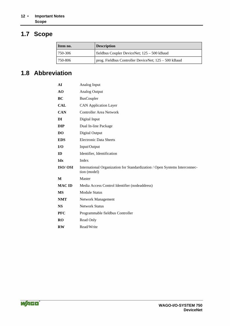
1.7 Scope
Item no. Description
750-306 fieldbus Coupler DeviceNet; 125 – 500 kBaud
750-806 prog. Fieldbus Controller DeviceNet; 125 – 500 kBaud
1.8 Abbreviation
AI Analog Input
AO Analog Output
BC BusCoupler
CAL CAN Application Layer
CAN Controller Area Network
DI Digital Input
DIP Dual In-line Package
DO Digital Output
EDS Electronic Data Sheets
I/O Input/Output
ID Identifier, Identification
Idx Index
ISO/ OSI International Organization for Standardization / Open Systems Interconnec-tion (model)
M Master
MAC ID Media Access Control Identifier (nodeaddress)
MS Module Status
NMT Network Management
NS Network Status
PFC Programmable fieldbus Controller
RO Read Only
RW Read/Write
The WAGO-I/O-SYSTEM 750 • 13 System Description
WAGO-I/O-SYSTEM 750 DeviceNet
2 The WAGO-I/O-SYSTEM 750 2.1 System Description
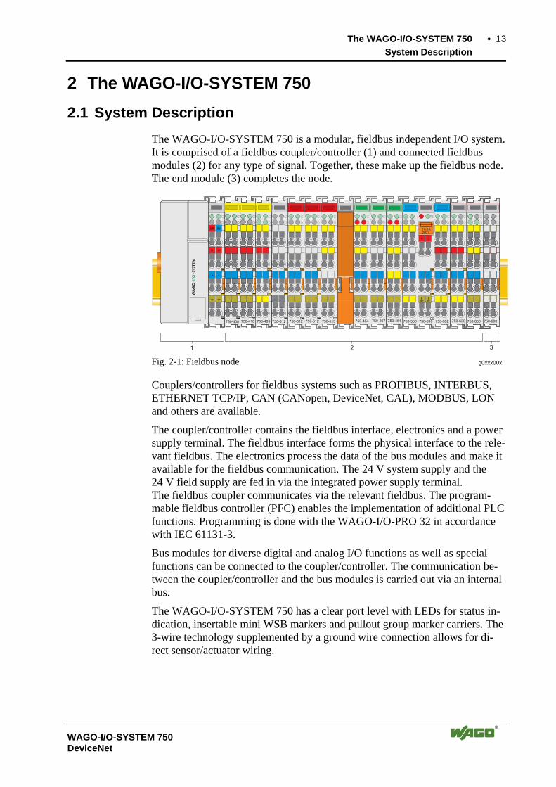
The WAGO-I/O-SYSTEM 750 is a modular, fieldbus independent I/O system. It is comprised of a fieldbus coupler/controller (1) and connected fieldbus modules (2) for any type of signal. Together, these make up the fieldbus node. The end module (3) completes the node.
Fig. 2-1: Fieldbus node g0xxx00x
Couplers/controllers for fieldbus systems such as PROFIBUS, INTERBUS, ETHERNET TCP/IP, CAN (CANopen, DeviceNet, CAL), MODBUS, LON and others are available.
The coupler/controller contains the fieldbus interface, electronics and a power supply terminal. The fieldbus interface forms the physical interface to the rele-vant fieldbus. The electronics process the data of the bus modules and make it available for the fieldbus communication. The 24 V system supply and the 24 V field supply are fed in via the integrated power supply terminal. The fieldbus coupler communicates via the relevant fieldbus. The program-mable fieldbus controller (PFC) enables the implementation of additional PLC functions. Programming is done with the WAGO-I/O-PRO 32 in accordance with IEC 61131-3.
Bus modules for diverse digital and analog I/O functions as well as special functions can be connected to the coupler/controller. The communication be-tween the coupler/controller and the bus modules is carried out via an internal bus.
The WAGO-I/O-SYSTEM 750 has a clear port level with LEDs for status in-dication, insertable mini WSB markers and pullout group marker carriers. The 3-wire technology supplemented by a ground wire connection allows for di-rect sensor/actuator wiring.
14 • The WAGO-I/O-SYSTEM 750 Technical Data
WAGO-I/O-SYSTEM 750 DeviceNet
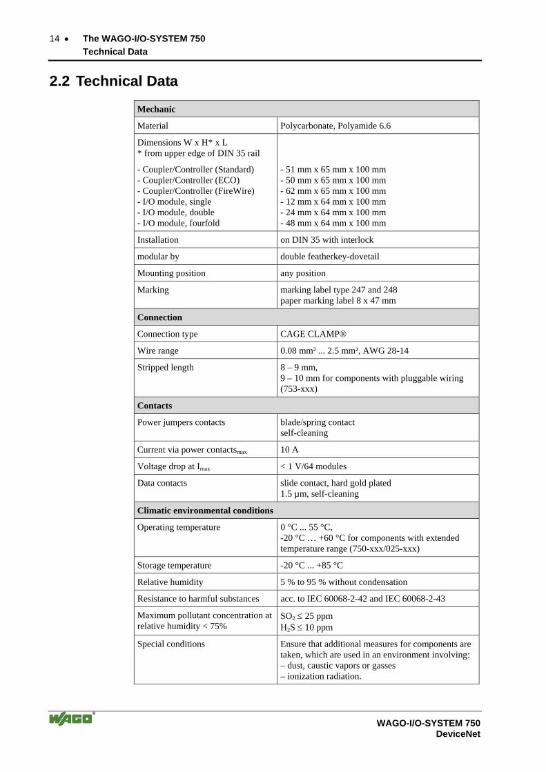
2.2 Technical Data
Mechanic
Material Polycarbonate, Polyamide 6.6
Dimensions W x H* x L * from upper edge of DIN 35 rail
- Coupler/Controller (Standard) - Coupler/Controller (ECO) - Coupler/Controller (FireWire) - I/O module, single - I/O module, double - I/O module, fourfold
- 51 mm x 65 mm x 100 mm - 50 mm x 65 mm x 100 mm - 62 mm x 65 mm x 100 mm - 12 mm x 64 mm x 100 mm - 24 mm x 64 mm x 100 mm - 48 mm x 64 mm x 100 mm
Installation on DIN 35 with interlock
modular by double featherkey-dovetail
Mounting position any position
Marking marking label type 247 and 248 paper marking label 8 x 47 mm
Connection
Connection type CAGE CLAMP®
Wire range 0.08 mm² ... 2.5 mm², AWG 28-14
Stripped length 8 – 9 mm, 9 – 10 mm for components with pluggable wiring (753-xxx)
Contacts
Power jumpers contacts blade/spring contact self-cleaning
Current via power contactsmax 10 A
Voltage drop at Imax < 1 V/64 modules
Data contacts slide contact, hard gold plated 1.5 µm, self-cleaning
Climatic environmental conditions
Operating temperature 0 °C ... 55 °C, -20 °C … +60 °C for components with extended temperature range (750-xxx/025-xxx)
Storage temperature -20 °C ... +85 °C
Relative humidity 5 % to 95 % without condensation
Resistance to harmful substances acc. to IEC 60068-2-42 and IEC 60068-2-43
Maximum pollutant concentration at relative humidity < 75%
SO2 ≤ 25 ppm H2S ≤ 10 ppm
Special conditions Ensure that additional measures for components are taken, which are used in an environment involving: – dust, caustic vapors or gasses – ionization radiation.
The WAGO-I/O-SYSTEM 750 • 15 Technical Data
WAGO-I/O-SYSTEM 750 DeviceNet
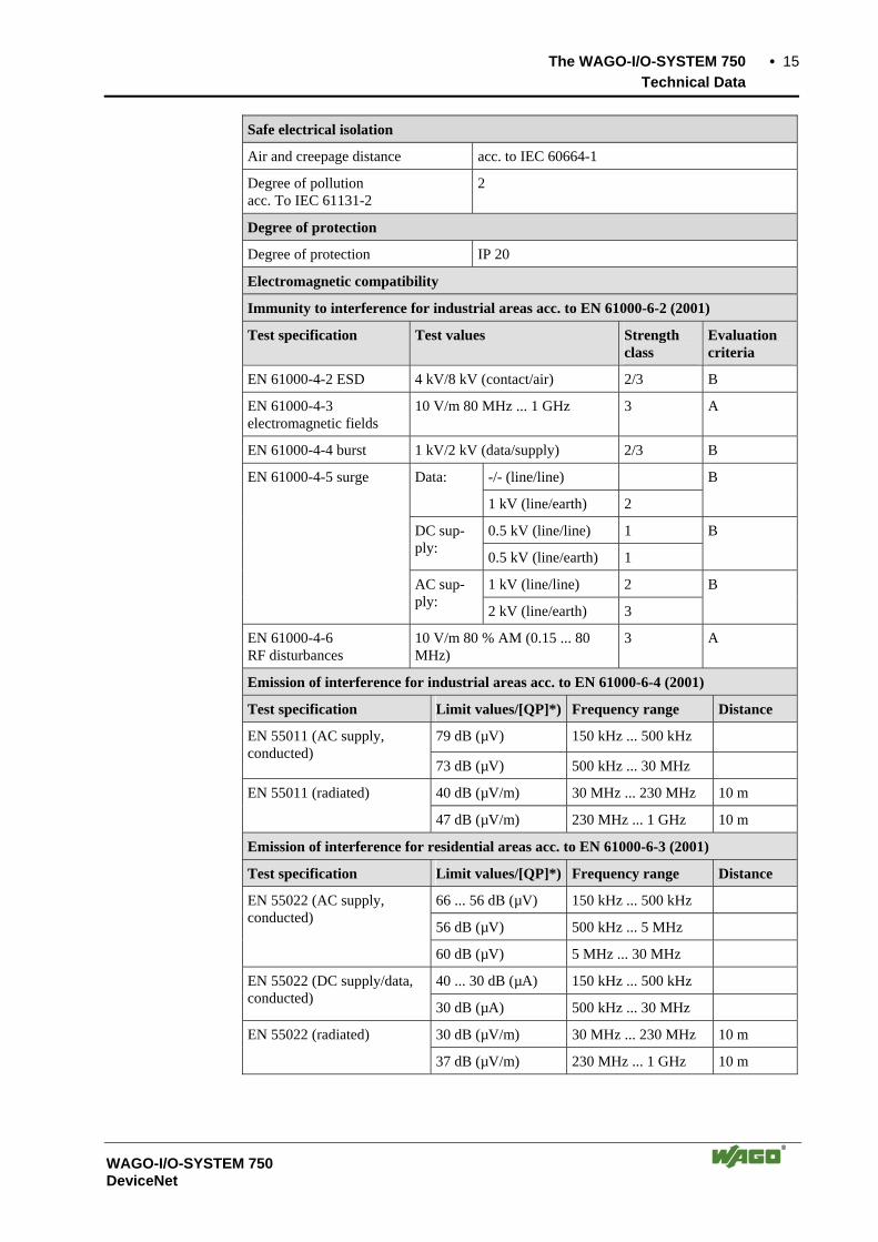
Safe electrical isolation
Air and creepage distance acc. to IEC 60664-1
Degree of pollution acc. To IEC 61131-2
2
Degree of protection
Degree of protection IP 20
Electromagnetic compatibility
Immunity to interference for industrial areas acc. to EN 61000-6-2 (2001)
Test specification Test values Strength class
Evaluation criteria
EN 61000-4-2 ESD 4 kV/8 kV (contact/air) 2/3 B
EN 61000-4-3 electromagnetic fields
10 V/m 80 MHz ... 1 GHz 3 A
EN 61000-4-4 burst 1 kV/2 kV (data/supply) 2/3 B
-/- (line/line) Data:
1 kV (line/earth) 2
B
0.5 kV (line/line) 1 DC sup-ply: 0.5 kV (line/earth) 1
B
1 kV (line/line) 2
EN 61000-4-5 surge
AC sup-ply: 2 kV (line/earth) 3
B
EN 61000-4-6 RF disturbances
10 V/m 80 % AM (0.15 ... 80 MHz)
3 A
Emission of interference for industrial areas acc. to EN 61000-6-4 (2001)
Test specification Limit values/[QP]*) Frequency range Distance
79 dB (µV) 150 kHz ... 500 kHz EN 55011 (AC supply, conducted)
73 dB (µV) 500 kHz ... 30 MHz
40 dB (µV/m) 30 MHz ... 230 MHz 10 m EN 55011 (radiated)
47 dB (µV/m) 230 MHz ... 1 GHz 10 m
Emission of interference for residential areas acc. to EN 61000-6-3 (2001)
Test specification Limit values/[QP]*) Frequency range Distance
66 ... 56 dB (µV) 150 kHz ... 500 kHz
56 dB (µV) 500 kHz ... 5 MHz
EN 55022 (AC supply, conducted)
60 dB (µV) 5 MHz ... 30 MHz
40 ... 30 dB (µA) 150 kHz ... 500 kHz EN 55022 (DC supply/data, conducted) 30 dB (µA) 500 kHz ... 30 MHz
30 dB (µV/m) 30 MHz ... 230 MHz 10 m EN 55022 (radiated)
37 dB (µV/m) 230 MHz ... 1 GHz 10 m

16 • The WAGO-I/O-SYSTEM 750 Technical Data
WAGO-I/O-SYSTEM 750 DeviceNet
Mechanical strength acc. to IEC 61131-2
Test specification Frequency range Limit value
5 Hz ≤ f < 9 Hz 1.75 mm amplitude (permanent) 3.5 mm amplitude (short term)
9 Hz ≤ f < 150 Hz 0.5 g (permanent) 1 g (short term)
IEC 60068-2-6 vibration
Note on vibration test: a) Frequency change: max. 1 octave/minute b) Vibration direction: 3 axes
15 g IEC 60068-2-27 shock
Note on shock test: a) Type of shock: half sine b) Shock duration: 11 ms c) Shock direction: 3x in positive and 3x in negative direc-tion for each of the three mutually perpendicular axes of the test specimen
IEC 60068-2-32 free fall 1 m (module in original packing)
*) QP: Quasi Peak
Note: If the technical data of components differ from the values described here, the technical data shown in the manuals of the respective components shall be valid.
The WAGO-I/O-SYSTEM 750 • 17 Technical Data
WAGO-I/O-SYSTEM 750 DeviceNet
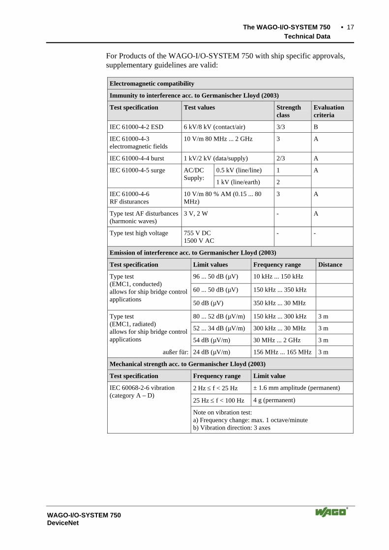
For Products of the WAGO-I/O-SYSTEM 750 with ship specific approvals, supplementary guidelines are valid:
Electromagnetic compatibility
Immunity to interference acc. to Germanischer Lloyd (2003)
Test specification Test values Strength class
Evaluation criteria
IEC 61000-4-2 ESD 6 kV/8 kV (contact/air) 3/3 B
IEC 61000-4-3 electromagnetic fields
10 V/m 80 MHz ... 2 GHz 3 A
IEC 61000-4-4 burst 1 kV/2 kV (data/supply) 2/3 A
0.5 kV (line/line) 1 IEC 61000-4-5 surge AC/DC Supply: 1 kV (line/earth) 2
A
IEC 61000-4-6 RF disturances
10 V/m 80 % AM (0.15 ... 80 MHz)
3 A
Type test AF disturbances (harmonic waves)
3 V, 2 W - A
Type test high voltage 755 V DC 1500 V AC
- -
Emission of interference acc. to Germanischer Lloyd (2003)
Test specification Limit values Frequency range Distance
96 ... 50 dB (µV) 10 kHz ... 150 kHz
60 ... 50 dB (µV) 150 kHz ... 350 kHz
Type test (EMC1, conducted) allows for ship bridge control applications 50 dB (µV) 350 kHz ... 30 MHz
80 ... 52 dB (µV/m) 150 kHz ... 300 kHz 3 m
52 ... 34 dB (µV/m) 300 kHz ... 30 MHz 3 m
Type test (EMC1, radiated) allows for ship bridge control applications 54 dB (µV/m) 30 MHz ... 2 GHz 3 m
außer für: 24 dB (µV/m) 156 MHz ... 165 MHz 3 m
Mechanical strength acc. to Germanischer Lloyd (2003)
Test specification Frequency range Limit value
2 Hz ≤ f < 25 Hz ± 1.6 mm amplitude (permanent)
25 Hz ≤ f < 100 Hz 4 g (permanent)
IEC 60068-2-6 vibration (category A – D)
Note on vibration test: a) Frequency change: max. 1 octave/minute b) Vibration direction: 3 axes

18 • The WAGO-I/O-SYSTEM 750 Technical Data
WAGO-I/O-SYSTEM 750 DeviceNet
Range of application
Required specification emission of interference
Required specification immunity to interference
Industrial areas EN 61000-6-4 (2001) EN 61000-6-2 (2001)
Residential areas EN 61000-6-3 (2001)*) EN 61000-6-1 (2001)
*) The system meets the requirements on emission of interference in residential areas with the fieldbus coupler/controller for:
ETHERNET
LonWorks
CANopen
DeviceNet
MODBUS
750-342/-841/-842/-860
750-319/-819
750-337/-837
750-306/-806
750-312/-314/ -315/ -316 750-812/-814/ -815/ -816
With a special permit, the system can also be implemented with other fieldbus cou-plers/controllers in residential areas (housing, commercial and business areas, small-scale enterprises). The special permit can be obtained from an authority or inspection office. In Germany, the Federal Office for Post and Telecommunications and its branch offices issues the permit.
It is possible to use other field bus couplers/controllers under certain boundary condi-tions. Please contact WAGO Kontakttechnik GmbH & Co. KG.
Maximum power dissipation of the components
Bus modules 0.8 W / bus terminal (total power dissipation, sys-tem/field)
Fieldbus coupler/controller 2.0 W / coupler/controller
Warning The power dissipation of all installed components must not exceed the maxi-mum conductible power of the housing (cabinet). When dimensioning the housing, care is to be taken that even under high ex-ternal temperatures, the temperature inside the housing does not exceed the permissible ambient temperature of 55 °C.

The WAGO-I/O-SYSTEM 750 • 19 Technical Data
WAGO-I/O-SYSTEM 750 DeviceNet
Dimensions
51
24V 0V
+ +
- -
01 02
C
DB
A
C
DB
A
C
DB
A
C
DB
A
C
DB
A
10
0
12 24
64
35
65
Side view Dimensions in mm Fig. 2-2: Dimensions g01xx05e
Note: The illustration shows a standard coupler. For detailed dimensions, please refer to the technical data of the respective coupler/controller.

20 • The WAGO-I/O-SYSTEM 750 Manufacturing Number
WAGO-I/O-SYSTEM 750 DeviceNet
2.3 Manufacturing Number The manufacturing number indicates the delivery status directly after produc-tion. This number is part of the lateral marking on the component. In addition, starting from calender week 43/2000 the manufacturing number is also printed on the cover of the configuration and programming interface of the fieldbus coupler or controller.
Hansastr. 27D-32423 Minden
ITEM-NO.:750-333
PROFIBUS DP 12 MBd /DPV1
0 V
Power SupplyElectronic
PATENTS PENDINGII 3 GDDEMKO 02 ATEX132273 XEEx nA II T4
24V
DC
AW
G28
-14
55°C
max
ambi
ent
LIS
TE
D22
ZA
AN
D22
XM
72
07
2
01
03
00
02
03
-B0
00
00
0
Hansastr. 27D-32423 Minden
ITEM-NO.:750-333
PROFIBUS DP 12 MBd /DPV1
0 V
Power SupplyElectronic
PATENTS PENDINGII 3 GDDEMKO 02 ATEX132273 XEEx nA II T4
24V
DC
AW
G28
-14
55°C
max
ambi
ent
LIS
TE
D22
ZA
AN
D22
XM
72
07
2
01
03
00
02
03
-B0
60
60
6
1 0 3 0 0 0 20 0 3
DS
NO
SW
HW
GL
FW
L
Power SupplyField
24 V+-
- B 0 6 0 6 0 6
PROFIBUS
WA
GO
-I/O
-SY
STEM
75
0-3
33
0103000203-B06060672072
Manufacturing Number
Calendarweek
Year Softwareversion
Hardwareversion
Firmware Loaderversion
InternalNumber
Fig. 2-3: Example: Manufacturing Number of a PROFIBUS fieldbus coupler 750-333 g01xx15e
The manufacturing number consists of the production week and year, the soft-ware version (if available), the hardware version of the component, the firm-ware loader (if available) and further internal information for WAGO Kontakttechnik GmbH.

The WAGO-I/O-SYSTEM 750 • 21 Component Update
WAGO-I/O-SYSTEM 750 DeviceNet
2.4 Component Update For the case of an Update of one component, the lateral marking on each com-ponent contains a prepared matrix.
This matrix makes columns available for altogether three updates to the entry of the current update data, like production order number (NO; starting from calendar week 13/2004), update date (DS), software version (SW), hardware version (HW) and the firmware loader version (FWL, if available).
Update Matrix
Current Version data for: 1. Update 2. Update 3. Update
Production Order Number
NO Only starting from calendar week 13/2004
Datestamp DS Software index SW Hardware index HW Firmware loader index FWL Only for coupler/ con-
troller
If the update of a component took place, the current version data are registered into the columns of the matrix.
Additionally with the update of a fieldbus coupler or controller also the cover of the configuration and programming interface of the coupler or controller is printed on with the current manufacturing and production order number.
The original manufacturing data on the housing of the component remain thereby.
2.5 Storage, Assembly and Transport Wherever possible, the components are to be stored in their original packag-ing. Likewise, the original packaging provides optimal protection during transport.
When assembling or repacking the components, the contacts must not be soiled or damaged. The components must be stored and transported in appro-priate containers/packaging. Thereby, the ESD information is to be regarded.
Statically shielded transport bags with metal coatings are to be used for the transport of open components for which soiling with amine, amide and sili-cone has been ruled out, e.g. 3M 1900E.
22 • The WAGO-I/O-SYSTEM 750 Mechanical Setup
WAGO-I/O-SYSTEM 750 DeviceNet
2.6 Mechanical Setup
2.6.1 Installation Position
Along with horizontal and vertical installation, all other installation positions are allowed.
Attention In the case of vertical assembly, an end stop has to be mounted as an addi-tional safeguard against slipping. WAGO item 249-116 End stop for DIN 35 rail, 6 mm wide WAGO item 249-117 End stop for DIN 35 rail, 10 mm wide
2.6.2 Total Expansion
The length of the module assembly (including one end module of 12mm width) that can be connected to the coupler/controller is 780mm. When as-sembled, the I/O modules have a maximum length of 768mm.
Examples:
• 64 I/O modules of 12mm width can be connected to one coupler/controller.
• 32 I/O modules of 24mm width can be connected to one coupler/controller.
Exception:
The number of connected I/O modules also depends on which type of cou-pler/controller is used. For example, the maximum number of I/O modules that can be connected to a Profibus coupler/controller is 63 without end mod-ule.The maximum total expansion of a node is calculated as follows:
Warning The maximum total length of a node without coupler/controller must not ex-ceed 780mm. Furthermore, restrictions made on certain types of cou-plers/controllers must be observed (e.g. for Profibus).

The WAGO-I/O-SYSTEM 750 • 23 Mechanical Setup
WAGO-I/O-SYSTEM 750 DeviceNet
2.6.3 Assembly onto Carrier Rail
2.6.3.1 Carrier rail properties
All system components can be snapped directly onto a carrier rail in accor-dance with the European standard EN 50022 (DIN 35).
Warning WAGO supplies standardized carrier rails that are optimal for use with the I/O system. If other carrier rails are used, then a technical inspection and ap-proval of the rail by WAGO Kontakttechnik GmbH should take place.
Carrier rails have different mechanical and electrical properties. For the opti-mal system setup on a carrier rail, certain guidelines must be observed:
• The material must be non-corrosive.
• Most components have a contact to the carrier rail to ground electro-magnetic disturbances. In order to avoid corrosion, this tin-plated carrier rail contact must not form a galvanic cell with the material of the carrier rail which generates a differential voltage above 0.5 V (saline solution of 0.3% at 20°C) .
• The carrier rail must optimally support the EMC measures integrated into the system and the shielding of the bus module connections.
• A sufficiently stable carrier rail should be selected and, if necessary, sev-eral mounting points (every 20 cm) should be used in order to prevent bending and twisting (torsion).
• The geometry of the carrier rail must not be altered in order to secure the safe hold of the components. In particular, when shortening or mounting the carrier rail, it must not be crushed or bent.
• The base of the I/O components extends into the profile of the carrier rail. For carrier rails with a height of 7.5 mm, mounting points are to be riveted under the node in the carrier rail (slotted head captive screws or blind riv-ets).
24 • The WAGO-I/O-SYSTEM 750 Mechanical Setup
WAGO-I/O-SYSTEM 750 DeviceNet
2.6.3.2 WAGO DIN Rail
WAGO carrier rails meet the electrical and mechanical requirements.
Item Number Description
210-113 /-112 35 x 7.5; 1 mm; steel yellow chromated; slotted/unslotted
210-114 /-197 35 x 15; 1.5 mm; steel yellow chromated; slotted/unslotted
210-118 35 x 15; 2.3 mm; steel yellow chromated; unslotted
210-198 35 x 15; 2.3 mm; copper; unslotted
210-196 35 x 7.5; 1 mm; aluminum; unslotted
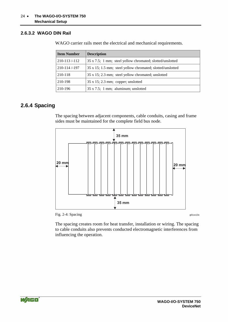
2.6.4 Spacing
The spacing between adjacent components, cable conduits, casing and frame sides must be maintained for the complete field bus node.
Fig. 2-4: Spacing g01xx13x
The spacing creates room for heat transfer, installation or wiring. The spacing to cable conduits also prevents conducted electromagnetic interferences from influencing the operation.

The WAGO-I/O-SYSTEM 750 • 25 Mechanical Setup
WAGO-I/O-SYSTEM 750 DeviceNet
2.6.5 Plugging and Removal of the Components
Warning Before work is done on the components, the voltage supply must be turned off.
In order to safeguard the coupler/controller from jamming, it should be fixed onto the carrier rail with the locking disc To do so, push on the upper groove of the locking disc using a screwdriver.
To pull out the fieldbus coupler/controller, release the locking disc by pressing on the bottom groove with a screwdriver and then pulling the orange colored unlocking lug.
Fig. 2-5: Coupler/Controller and unlocking lug g01xx12e
It is also possible to release an individual I/O module from the unit by pulling an unlocking lug.
Fig. 2-6: removing bus terminal p0xxx01x
Danger Ensure that an interruption of the PE will not result in a condition which could endanger a person or equipment! For planning the ring feeding of the ground wire, please see chapter 2.6.3.

26 • The WAGO-I/O-SYSTEM 750 Mechanical Setup
WAGO-I/O-SYSTEM 750 DeviceNet
2.6.6 Assembly Sequence
All system components can be snapped directly on a carrier rail in accordance with the European standard EN 50022 (DIN 35).
The reliable positioning and connection is made using a tongue and groove system. Due to the automatic locking, the individual components are securely seated on the rail after installing.
Starting with the coupler/controller, the bus modules are assembled adjacent to each other according to the project planning. Errors in the planning of the node in terms of the potential groups (connection via the power contacts) are recognized, as the bus modules with power contacts (male contacts) cannot be linked to bus modules with fewer power contacts.
Attention Always link the bus modules with the coupler/controller, and always plug from above.
Warning Never plug bus modules from the direction of the end terminal. A ground wire power contact, which is inserted into a terminal without contacts, e.g. a 4-channel digital input module, has a decreased air and creepage distance to the neighboring contact in the example DI4. Always terminate the fieldbus node with an end module (750-600).

The WAGO-I/O-SYSTEM 750 • 27 Mechanical Setup
WAGO-I/O-SYSTEM 750 DeviceNet
2.6.7 Internal Bus/Data Contacts
Communication between the coupler/controller and the bus modules as well as the system supply of the bus modules is carried out via the internal bus. It is comprised of 6 data contacts, which are available as self-cleaning gold spring contacts.
Fig. 2-7: Data contacts p0xxx07x
Warning Do not touch the gold spring contacts on the I/O modules in order to avoid soiling or scratching!
ESD (Electrostatic Discharge) The modules are equipped with electronic components that may be destroyed by electrostatic discharge. When handling the modules, ensure that the envi-ronment (persons, workplace and packing) is well grounded. Avoid touching conductive components, e.g. gold contacts.
28 • The WAGO-I/O-SYSTEM 750 Mechanical Setup
WAGO-I/O-SYSTEM 750 DeviceNet
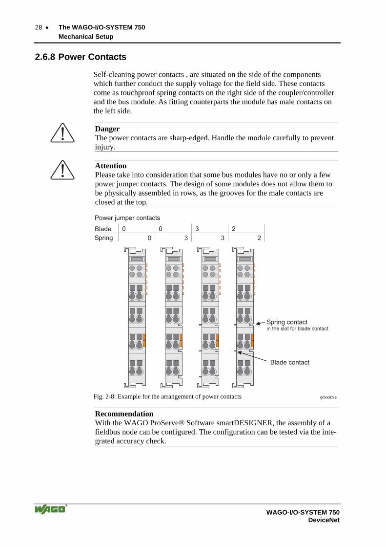
2.6.8 Power Contacts
Self-cleaning power contacts , are situated on the side of the components which further conduct the supply voltage for the field side. These contacts come as touchproof spring contacts on the right side of the coupler/controller and the bus module. As fitting counterparts the module has male contacts on the left side.
Danger The power contacts are sharp-edged. Handle the module carefully to prevent injury.
Attention Please take into consideration that some bus modules have no or only a few power jumper contacts. The design of some modules does not allow them to be physically assembled in rows, as the grooves for the male contacts are closed at the top.
Fig. 2-8: Example for the arrangement of power contacts g0xxx05e
Recommendation With the WAGO ProServe® Software smartDESIGNER, the assembly of a fieldbus node can be configured. The configuration can be tested via the inte-grated accuracy check.
The WAGO-I/O-SYSTEM 750 • 29 Mechanical Setup
WAGO-I/O-SYSTEM 750 DeviceNet
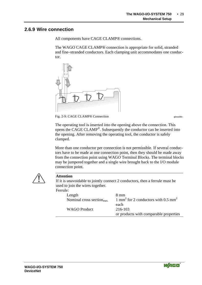
2.6.9 Wire connection
All components have CAGE CLAMP® connections.
The WAGO CAGE CLAMP® connection is appropriate for solid, stranded and fine–stranded conductors. Each clamping unit accommodates one conduc-tor.
Fig. 2-9: CAGE CLAMP® Connection g0xxx08x
The operating tool is inserted into the opening above the connection. This opens the CAGE CLAMP®. Subsequently the conductor can be inserted into the opening. After removing the operating tool, the conductor is safely clamped.
More than one conductor per connection is not permissible. If several conduc-tors have to be made at one connection point, then they should be made away from the connection point using WAGO Terminal Blocks. The terminal blocks may be jumpered together and a single wire brought back to the I/O module connection point.
Attention If it is unavoidable to jointly connect 2 conductors, then a ferrule must be used to join the wires together. Ferrule: Length 8 mm Nominal cross sectionmax. 1 mm2 for 2 conductors with 0.5 mm2 each WAGO Product 216-103 or products with comparable properties
30 • The WAGO-I/O-SYSTEM 750 Power Supply
WAGO-I/O-SYSTEM 750 DeviceNet
2.7 Power Supply
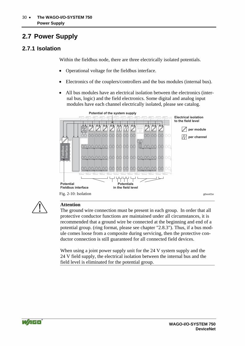
2.7.1 Isolation
Within the fieldbus node, there are three electrically isolated potentials.
• Operational voltage for the fieldbus interface.
• Electronics of the couplers/controllers and the bus modules (internal bus).
• All bus modules have an electrical isolation between the electronics (inter-nal bus, logic) and the field electronics. Some digital and analog input modules have each channel electrically isolated, please see catalog.
Fig. 2-10: Isolation g0xxx01e
Attention The ground wire connection must be present in each group. In order that all protective conductor functions are maintained under all circumstances, it is recommended that a ground wire be connected at the beginning and end of a potential group. (ring format, please see chapter "2.8.3"). Thus, if a bus mod-ule comes loose from a composite during servicing, then the protective con-ductor connection is still guaranteed for all connected field devices. When using a joint power supply unit for the 24 V system supply and the 24 V field supply, the electrical isolation between the internal bus and the field level is eliminated for the potential group.

The WAGO-I/O-SYSTEM 750 • 31 Power Supply
WAGO-I/O-SYSTEM 750 DeviceNet
2.7.2 System Supply
2.7.2.1 Connection
The WAGO-I/O-SYSTEM 750 requires a 24 V direct current system supply (-15% or +20 %). The power supply is provided via the coupler/controller and, if necessary, in addition via the internal system supply modules (750-613). The voltage supply is reverse voltage protected.
Attention The use of an incorrect supply voltage or frequency can cause severe damage to the component.
Fig. 2-11: System Supply g0xxx02e
The direct current supplies all internal system components, e.g. cou-pler/controller electronics, fieldbus interface and bus modules via the internal bus (5 V system voltage). The 5 V system voltage is electrically connected to the 24 V system supply.
Fig. 2-12: System Voltage g0xxx06e

32 • The WAGO-I/O-SYSTEM 750 Power Supply
WAGO-I/O-SYSTEM 750 DeviceNet
Attention Resetting the system by switching on and off the system supply, must take place simultaneously for all supply modules (coupler/controller and 750-613).
2.7.2.2 Alignment
Recommendation A stable network supply cannot be taken for granted always and everywhere. Therefore, regulated power supply units should be used in order to guarantee the quality of the supply voltage.
The supply capacity of the coupler/controller or the internal system supply module (750-613) can be taken from the technical data of the components.
Internal current consumption*) Current consumption via system voltage: 5 V for electronics of the bus modules and cou-pler/controller
Residual current for bus termi-nals*)
Available current for the bus modules. Provided by the bus power supply unit. See coupler/controller and internal system supply module (750-613)
*) cf. catalogue W4 Volume 3, manuals or Internet
Example Coupler 750-301: internal current consumption:350 mA at 5V residual current for bus modules : 1650 mA at 5V sum I(5V) total : 2000 mA at 5V
The internal current consumption is indicated in the technical data for each bus terminal. In order to determine the overall requirement, add together the values of all bus modules in the node.
Attention If the sum of the internal current consumption exceeds the residual current for bus modules, then an internal system supply module (750-613) must be placed before the module where the permissible residual current was ex-ceeded.
Example: A node with a PROFIBUS Coupler 750-333 consists of 20 relay mod-ules (750-517) and 10 digital input modules (750-405).
Current consumption: 20* 90 mA = 1800 mA 10* 2 mA = 20 mA Sum 1820 mA
The coupler can provide 1650 mA for the bus modules. Consequently, an internal system supply module (750-613), e.g. in the middle of the node, should be added.

The WAGO-I/O-SYSTEM 750 • 33 Power Supply
WAGO-I/O-SYSTEM 750 DeviceNet
Recommendation With the WAGO ProServe® Software smartDESIGNER, the assembly of a fieldbus node can be configured. The configuration can be tested via the inte-grated accuracy check.
The maximum input current of the 24 V system supply is 500 mA. The exact electrical consumption (I(24 V)) can be determined with the following formulas:
Coupler/Controller
I(5 V) total = Sum of all the internal current consumption of the connected bus modules + internal current consumption coupler/controller
750-613
I(5 V) total = Sum of all the internal current consumption of the connected bus modules
Input current I(24 V) = 5 V / 24 V * I(5 V) total / η
η = 0.87 (at nominal load)
Note If the electrical consumption of the power supply point for the 24 V-system supply exceeds 500 mA, then the cause may be an improperly aligned node or a defect.
During the test, all outputs, in particular those of the relay modules, must be active.
34 • The WAGO-I/O-SYSTEM 750 Power Supply
WAGO-I/O-SYSTEM 750 DeviceNet
2.7.3 Field Supply
2.7.3.1 Connection
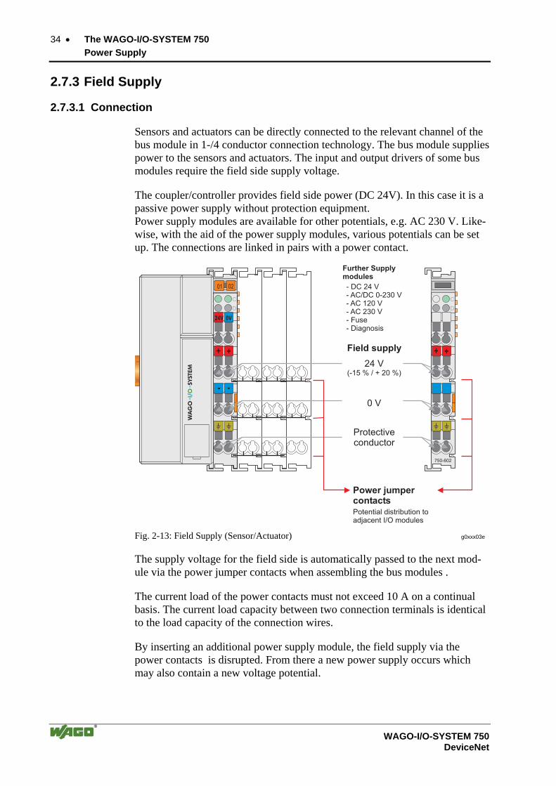
Sensors and actuators can be directly connected to the relevant channel of the bus module in 1-/4 conductor connection technology. The bus module supplies power to the sensors and actuators. The input and output drivers of some bus modules require the field side supply voltage.
The coupler/controller provides field side power (DC 24V). In this case it is a passive power supply without protection equipment. Power supply modules are available for other potentials, e.g. AC 230 V. Like-wise, with the aid of the power supply modules, various potentials can be set up. The connections are linked in pairs with a power contact.
Fig. 2-13: Field Supply (Sensor/Actuator) g0xxx03e
The supply voltage for the field side is automatically passed to the next mod-ule via the power jumper contacts when assembling the bus modules .
The current load of the power contacts must not exceed 10 A on a continual basis. The current load capacity between two connection terminals is identical to the load capacity of the connection wires.
By inserting an additional power supply module, the field supply via the power contacts is disrupted. From there a new power supply occurs which may also contain a new voltage potential.

The WAGO-I/O-SYSTEM 750 • 35 Power Supply
WAGO-I/O-SYSTEM 750 DeviceNet
Attention Some bus modules have no or very few power contacts (depending on the I/O function). Due to this, the passing through of the relevant potential is dis-rupted. If a field supply is required for subsequent bus modules, then a power supply module must be used. Note the data sheets of the bus modules. In the case of a node setup with different potentials, e.g. the alteration from DC 24 V to AC 230V, a spacer module should be used. The optical separa-tion of the potentials acts as a warning to heed caution in the case of wiring and maintenance works. Thus, the results of wiring errors can be prevented.
2.7.3.2 Fusing
Internal fusing of the field supply is possible for various field voltages via an appropriate power supply module.
750-601 24 V DC, Supply/Fuse
750-609 230 V AC, Supply/Fuse
750-615 120 V AC, Supply/Fuse
750-610 24 V DC, Supply/Fuse/Diagnosis
750-611 230 V AC, Supply/Fuse/Diagnosis
Fig. 2-14: Supply module with fuse carrier (Example 750-610) g0xxx09x
36 • The WAGO-I/O-SYSTEM 750 Power Supply
WAGO-I/O-SYSTEM 750 DeviceNet
Warning In the case of power supply modules with fuse holders, only fuses with a maximum dissipation of 1.6 W (IEC 127) must be used. For UL approved systems only use UL approved fuses.
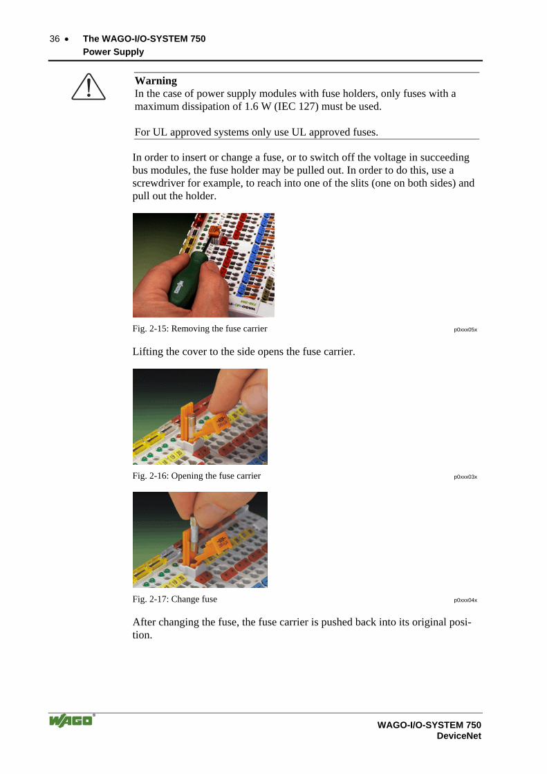
In order to insert or change a fuse, or to switch off the voltage in succeeding bus modules, the fuse holder may be pulled out. In order to do this, use a screwdriver for example, to reach into one of the slits (one on both sides) and pull out the holder.
Fig. 2-15: Removing the fuse carrier p0xxx05x
Lifting the cover to the side opens the fuse carrier.
Fig. 2-16: Opening the fuse carrier p0xxx03x
Fig. 2-17: Change fuse p0xxx04x
After changing the fuse, the fuse carrier is pushed back into its original posi-tion.
The WAGO-I/O-SYSTEM 750 • 37 Power Supply
WAGO-I/O-SYSTEM 750 DeviceNet
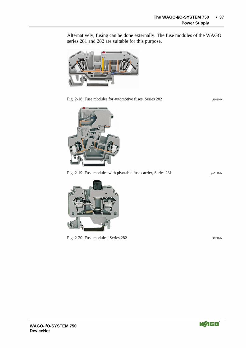
Alternatively, fusing can be done externally. The fuse modules of the WAGO series 281 and 282 are suitable for this purpose.
Fig. 2-18: Fuse modules for automotive fuses, Series 282 pf66800x
Fig. 2-19: Fuse modules with pivotable fuse carrier, Series 281 pe61100x
Fig. 2-20: Fuse modules, Series 282 pf12400x

38 • The WAGO-I/O-SYSTEM 750 Power Supply
WAGO-I/O-SYSTEM 750 DeviceNet
2.7.4 Supplementary power supply regulations
The WAGO-I/O-SYSTEM 750 can also be used in shipbuilding or offshore and onshore areas of work (e.g. working platforms, loading plants). This is demonstrated by complying with the standards of influential classification companies such as Germanischer Lloyd and Lloyds Register.
Filter modules for 24-volt supply are required for the certified operation of the system.
Item No. Name Description
750-626 Supply filter Filter module for system supply and field supply (24 V, 0 V), i.e. for field bus coupler/controller and bus power supply (750-613)
750-624 Supply filter Filter module for the 24 V- field supply (750-602, 750-601, 750-610)
Therefore, the following power supply concept must be absolutely complied with.
Fig. 2-21: Power supply concept g01xx11e
Note Another potential power terminal 750-601/602/610 must only be used behind the filter terminal 750-626 if the protective earth conductor is needed on the lower power contact or if a fuse protection is required.

The WAGO-I/O-SYSTEM 750 • 39 Power Supply
WAGO-I/O-SYSTEM 750 DeviceNet
2.7.5 Supply example
Note The system supply and the field supply should be separated in order to ensure bus operation in the event of a short-circuit on the actuator side.
750-630750-400 750-410 750-401 750-613 750-512 750-512750-616 750-513 750-610 750-552 750-600750-612 750-616
1)a) b) c) d)1)
2) 2)
24V
24V
10 A
10
A
L1
L2
L3
N
PE
230V
230V
Main ground bus
Shield (screen) bus
SystemSupply
FieldSupply
FieldSupply 1) Separation module
recommended2) Ring-feeding
recommended
a) Power Supplyon coupler / controllervia external SupplyModule
b) Internal SystemSupply Module
c) Supply Modulepassive
d)
iagnostics
Supply Modulewith fuse carrier/d
Fig. 2-22: Supply example g0xxx04e

40 • The WAGO-I/O-SYSTEM 750 Power Supply
WAGO-I/O-SYSTEM 750 DeviceNet
2.7.6 Power Supply Unit
The WAGO-I/O-SYSTEM 750 requires a 24 V direct current system supply with a maximum deviation of -15% or +20 %.
Recommendation A stable network supply cannot be taken for granted always and everywhere. Therefore, regulated power supply units should be used in order to guarantee the quality of the supply voltage.
A buffer (200 µF per 1 A current load) should be provided for brief voltage dips. The I/O system buffers for approx 1 ms.
The electrical requirement for the field supply is to be determined individually for each power supply point. Thereby all loads through the field devices and bus modules should be considered. The field supply as well influences the bus modules, as the inputs and outputs of some bus modules require the voltage of the field supply.
Note The system supply and the field supply should be isolated from the power supplies in order to ensure bus operation in the event of short circuits on the actuator side.
WAGO products Article No.
Description
787-903 Primary switched - mode, DC 24 V, 5 A wide input voltage range AC 85-264 V PFC (Power Factor Correction)
787-904 Primary switched - mode, DC 24 V, 10 A wide input voltage range AC 85-264 V PFC (Power Factor Correction)
787-912 Primary switched - mode, DC 24 V, 2 A wide input voltage range AC 85-264 V PFC (Power Factor Correction)
288-809 288-810 288-812 288-813
Rail-mounted modules with universal mounting carrier
AC 115 V / DC 24 V; 0,5 A AC 230 V / DC 24 V; 0,5 A AC 230 V / DC 24 V; 2 A AC 115 V / DC 24 V; 2 A
The WAGO-I/O-SYSTEM 750 • 41 Grounding
WAGO-I/O-SYSTEM 750 DeviceNet
2.8 Grounding
2.8.1 Grounding the DIN Rail
2.8.1.1 Framework Assembly
When setting up the framework, the carrier rail must be screwed together with the electrically conducting cabinet or housing frame. The framework or the housing must be grounded. The electronic connection is established via the screw. Thus, the carrier rail is grounded.
Attention Care must be taken to ensure the flawless electrical connection between the carrier rail and the frame or housing in order to guarantee sufficient ground-ing.
2.8.1.2 Insulated Assembly
Insulated assembly has been achieved when there is constructively no direct conduction connection between the cabinet frame or machine parts and the carrier rail. Here the earth must be set up via an electrical conductor.
The connected grounding conductor should have a cross section of at least 4 mm2.
Recommendation The optimal insulated setup is a metallic assembly plate with grounding con-nection with an electrical conductive link with the carrier rail.
The separate grounding of the carrier rail can be easily set up with the aid of the WAGO ground wire terminals.
Article No. Description
283-609 Single-conductor ground (earth) terminal block make an automatic contact to the carrier rail; conductor cross section: 0.2 -16 mm2 Note: Also order the end and intermediate plate (283-320)
42 • The WAGO-I/O-SYSTEM 750 Grounding
WAGO-I/O-SYSTEM 750 DeviceNet
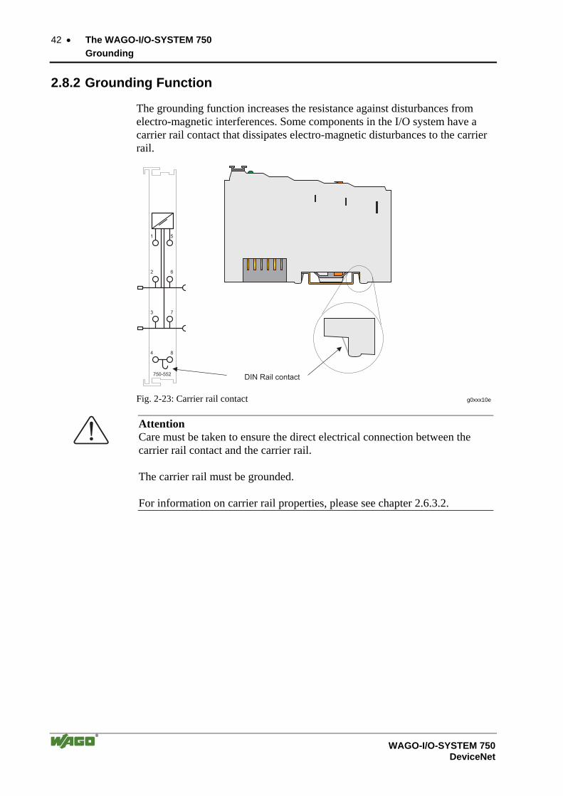
2.8.2 Grounding Function
The grounding function increases the resistance against disturbances from electro-magnetic interferences. Some components in the I/O system have a carrier rail contact that dissipates electro-magnetic disturbances to the carrier rail.
Fig. 2-23: Carrier rail contact g0xxx10e
Attention Care must be taken to ensure the direct electrical connection between the carrier rail contact and the carrier rail. The carrier rail must be grounded. For information on carrier rail properties, please see chapter 2.6.3.2.

The WAGO-I/O-SYSTEM 750 • 43 Grounding
WAGO-I/O-SYSTEM 750 DeviceNet
2.8.3 Grounding Protection
For the field side, the ground wire is connected to the lowest connection ter-minals of the power supply module. The ground connection is then connected to the next module via the Power Jumper Contact (PJC). If the bus module has the lower power jumper contact, then the ground wire connection of the field devices can be directly connected to the lower connection terminals of the bus module.
Attention Should the ground conductor connection of the power jumper contacts within the node become disrupted, e.g. due to a 4-channel bus terminal, the ground connection will need to be re-established.
The ring feeding of the grounding potential will increase the system safety. When one bus module is removed from the group, the grounding connection will remain intact.
The ring feeding method has the grounding conductor connected to the begin-ning and end of each potential group.
Fig. 2-24: Ring-feeding g0xxx07e
Attention The regulations relating to the place of assembly as well as the national regu-lations for maintenance and inspection of the grounding protection must be observed.
44 • The WAGO-I/O-SYSTEM 750 Shielding (Screening)
WAGO-I/O-SYSTEM 750 DeviceNet
2.9 Shielding (Screening)
2.9.1 General
The shielding of the data and signal conductors reduces electromagnetic inter-ferences thereby increasing the signal quality. Measurement errors, data trans-mission errors and even disturbances caused by overvoltage can be avoided.
Attention Constant shielding is absolutely required in order to ensure the technical specifications in terms of the measurement accuracy. The data and signal conductors should be separated from all high-voltage cables. The cable shield should be potential. With this, incoming disturbances can be easily diverted. The shielding should be placed over the entrance of the cabinet or housing in order to already repel disturbances at the entrance.
2.9.2 Bus Conductors
The shielding of the bus conductor is described in the relevant assembly guidelines and standards of the bus system.
2.9.3 Signal Conductors
Bus modules for most analog signals along with many of the interface bus modules include a connection for the shield.
Note For better shield performance, the shield should have previously been placed over a large area. The WAGO shield connection system is suggested for such an application. This suggestion is especially applicable when the equipment can have even current or high impulse formed currents running through it (for example through atmospheric end loading).

The WAGO-I/O-SYSTEM 750 • 45 Assembly Guidelines/Standards
WAGO-I/O-SYSTEM 750 DeviceNet
2.9.4 WAGO Shield (Screen) Connecting System
The WAGO Shield Connecting system includes a shield clamping saddle, a collection of rails and a variety of mounting feet. Together these allow many dfferent possibilities. See catalog W4 volume 3 chapter 10.
Fig. 2-25: WAGO Shield (Screen) Connecting System p0xxx08x, p0xxx09x, and p0xxx10x
Fig. 2-26: Application of the WAGO Shield (Screen) Connecting System p0xxx11x
2.10 Assembly Guidelines/Standards DIN 60204, Electrical equipping of machines
DIN EN 50178 Equipping of high-voltage systems with electronic components (replacement for VDE 0160)
EN 60439 Low voltage – switch box combinations

46 • Fieldbus Coupler 750-306 Description
WAGO-I/O-SYSTEM 750 DeviceNet
3 Fieldbus Coupler/Controller 3.1 Fieldbus Coupler 750-306
3.1.1 Description
The fieldbus Coupler 750-306 displays the peripheral data of all I/O modules in the WAGO-I/O-SYSTEM 750 on DeviceNet Feldbus. The data is transmit-ted with objects.
The bus Coupler determines the physical structure of the node and creates a process image from this with all inputs and outputs. This could involve a mixed arrangement of analog (word by word data exchange) and digital (byte by byte data exchange) modules.
The local process image is subdivided into an input and output data area. The process data can be read in via the DeviceNet bus and further processed in a control system. The process output data is sent via the DeviceNet bus.
The data of the analog modules are mapped into the automatical created proc-ess image according to the order of their position downstream of the bus Cou-pler. The bits of the digital modules are compiled to form bytes and also mapped into the process image attached to the data of the analog modules. Should the number of digital I/Os exceed 8 bits, the Coupler automatically starts another byte.
The fieldbus Coupler supports the DeviceNet function Bit-Strobe, whereby the function is insofar restricted, that only the status byte will be delivered.

Fieldbus Coupler 750-306 • 47 Hardware
WAGO-I/O-SYSTEM 750 DeviceNet
3.1.2 Hardware
3.1.2.1 View
24V 0V
+ +
Ñ Ñ
PE PE
01 02
750-
306
OVERFL
RUN
BUS OFF
I/O
DeviceNet
C
DB
A
CONNECTNS
12
34
56
78
ON
MS
Supply24V0V
0V
Power jumpercontacts
Statusvoltage supply-Power jumpercontacts-System
Supply viapower jumpercontacts24V
Data contactsFieldbusconnectionSeries 231(MCS)
Configurationinterface
DIP switchfor MAC IDand baud rate
flapopened
Fig. 3-1: Fieldbus Coupler 750-306 DeviceNet g030600e
The fieldbus Coupler comprises of:
• Supply module with Internal system supply module for the system supply as well as power jumper contacts for the field supply via I/O module as-semblies.
• Fieldbus interface with the bus connection
• DIP switch for baud rate and MAC ID
• Display elements (LED's) for status display of the operation, the bus com-munication, the operating voltages as well as for fault messages and diag-nosis
• Configuration interface
• Electronics for communication with the I/O modules (internal bus) and the fieldbus interface

48 • Fieldbus Coupler 750-306 Hardware
WAGO-I/O-SYSTEM 750 DeviceNet
3.1.2.2 Device Supply
The supply is made via terminal blocks with CAGE CLAMP® connection. The device supply is intended both for the system and the field units.
1
2
3
4
5
6
7
8
750-306
24V
10nF
24V
10nF
0V
DC
DC24V/0V
24V
0V
0V
1) 2)
2) 10nF/500V
1) 1M
ELECTRONICS
Busmodules
FIELDBUSINTERFACE
EL
EC
TR
ON
ICS
FIE
LD
BU
SIN
TE
RFA
CE
Fig. 3-2: Device supply g030601e
The integrated internal system supply module generates the necessary voltage to supply the electronics and the connected I/O modules.
The fieldbus interface is supplied with electrically isolated voltage from the internal system supply module.
Fieldbus Coupler 750-306 • 49 Hardware
WAGO-I/O-SYSTEM 750 DeviceNet
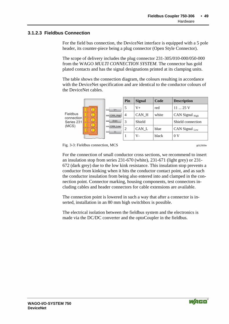
3.1.2.3 Fieldbus Connection
For the field bus connection, the DeviceNet interface is equipped with a 5 pole header, its counter-piece being a plug connector (Open Style Connector).
The scope of delivery includes the plug connector 231-305/010-000/050-000 from the WAGO MULTI CONNECTION SYSTEM. The connector has gold plated contacts and has the signal designations printed at its clamping units.
The table shows the connection diagram, the colours resulting in accordance with the DeviceNet specification and are identical to the conductor colours of the DeviceNet cables.
Pin Signal Code Description
5 V+ red 11 ... 25 V
4 CAN_H white CAN Signal High
3 Shield Shield connection
2 CAN_L blue CAN Signal Low
FieldbusconnectionSeries 231(MCS)
CAN_High
drain
CAN_Low
V-
V+
1 V- black 0 V
Fig. 3-3: Fieldbus connection, MCS g012500e
For the connection of small conductor cross sections, we recommend to insert an insulation stop from series 231-670 (white), 231-671 (light grey) or 231-672 (dark grey) due to the low kink resistance. This insulation stop prevents a conductor from kinking when it hits the conductor contact point, and as such the conductor insulation from being also entered into and clamped in the con-nection point. Connector marking, housing components, test connectors in-cluding cables and header connectors for cable extensions are available.
The connection point is lowered in such a way that after a connector is in-serted, installation in an 80 mm high switchbox is possible.
The electrical isolation between the fieldbus system and the electronics is made via the DC/DC converter and the optoCoupler in the fieldbus.
50 • Fieldbus Coupler 750-306 Hardware
WAGO-I/O-SYSTEM 750 DeviceNet
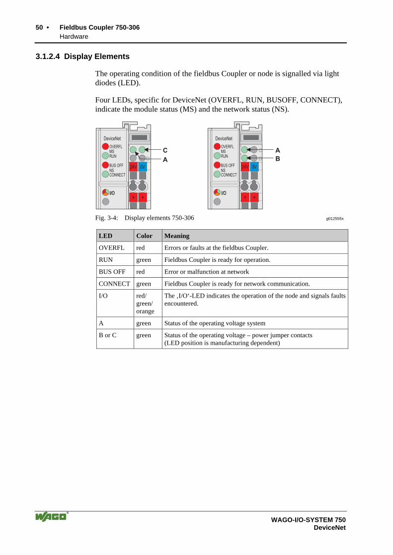
3.1.2.4 Display Elements
The operating condition of the fieldbus Coupler or node is signalled via light diodes (LED).
Four LEDs, specific for DeviceNet (OVERFL, RUN, BUSOFF, CONNECT), indicate the module status (MS) and the network status (NS).
24V 24V0V 0V
+ ++ +
OVERFL
RUN
BUS OFF
DeviceNet
C C
D DB B
A A
CONNECT
I/OI/O I/OI/O
DeviceNet
MS
NS
OVERFL
RUN
BUS OFF
CONNECT
MS
NS
C A
A B
Fig. 3-4: Display elements 750-306 g012555x
LED Color Meaning
OVERFL red Errors or faults at the fieldbus Coupler.
RUN green Fieldbus Coupler is ready for operation.
BUS OFF red Error or malfunction at network
CONNECT green Fieldbus Coupler is ready for network communication.
I/O red/ green/ orange
The ‚I/O‘-LED indicates the operation of the node and signals faults encountered.
A green Status of the operating voltage system
B or C green Status of the operating voltage – power jumper contacts (LED position is manufacturing dependent)
Fieldbus Coupler 750-306 • 51 Hardware
WAGO-I/O-SYSTEM 750 DeviceNet
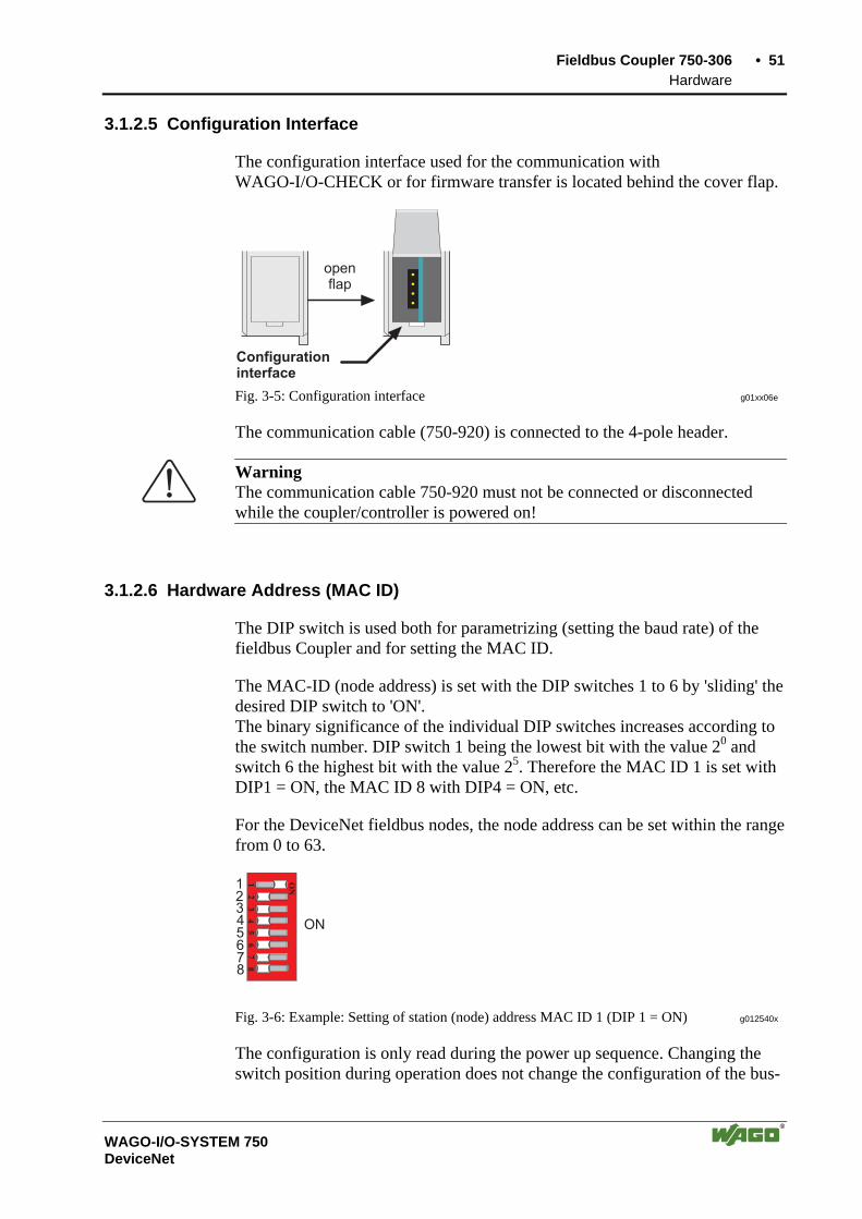
3.1.2.5 Configuration Interface
The configuration interface used for the communication with WAGO-I/O-CHECK or for firmware transfer is located behind the cover flap.
Configurationinterface
openflap
Fig. 3-5: Configuration interface g01xx06e
The communication cable (750-920) is connected to the 4-pole header.
Warning The communication cable 750-920 must not be connected or disconnected while the coupler/controller is powered on!
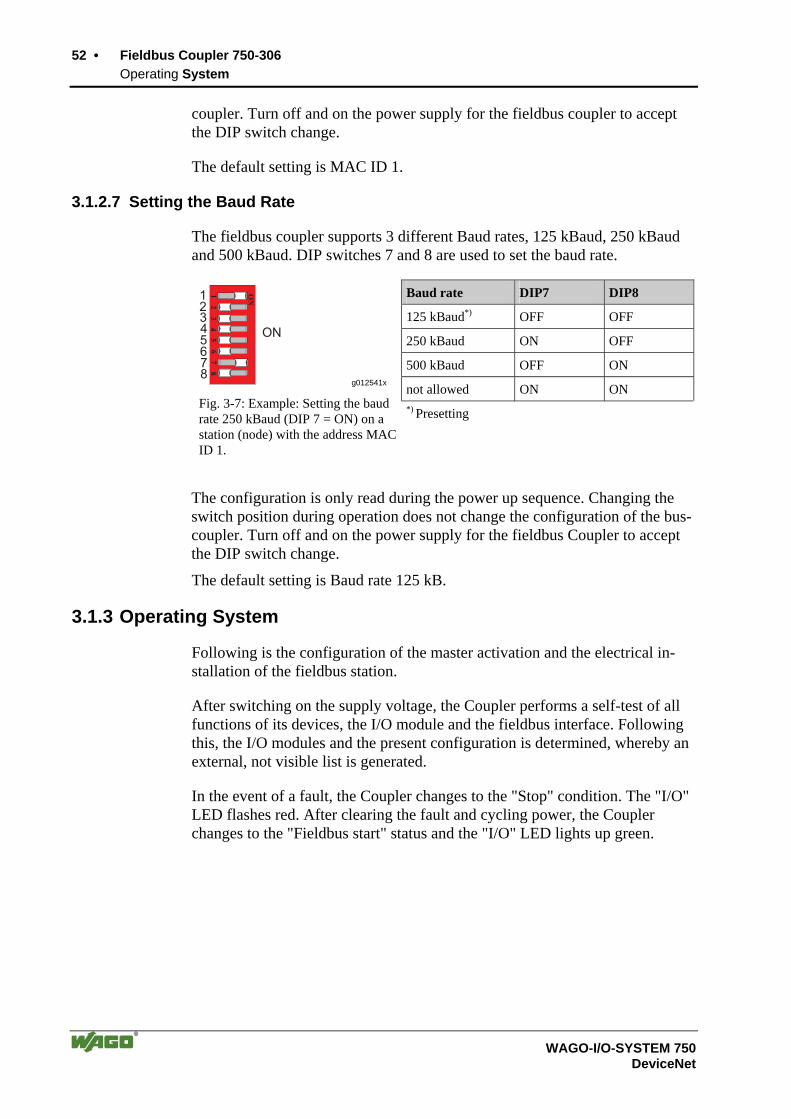
3.1.2.6 Hardware Address (MAC ID)
The DIP switch is used both for parametrizing (setting the baud rate) of the fieldbus Coupler and for setting the MAC ID.
The MAC-ID (node address) is set with the DIP switches 1 to 6 by 'sliding' the desired DIP switch to 'ON'. The binary significance of the individual DIP switches increases according to the switch number. DIP switch 1 being the lowest bit with the value 20 and switch 6 the highest bit with the value 25. Therefore the MAC ID 1 is set with DIP1 = ON, the MAC ID 8 with DIP4 = ON, etc.
For the DeviceNet fieldbus nodes, the node address can be set within the range from 0 to 63.
12
34
5
ON
67
8
12345678
ON
Fig. 3-6: Example: Setting of station (node) address MAC ID 1 (DIP 1 = ON) g012540x
The configuration is only read during the power up sequence. Changing the switch position during operation does not change the configuration of the bus-
52 • Fieldbus Coupler 750-306 Operating System
WAGO-I/O-SYSTEM 750 DeviceNet
coupler. Turn off and on the power supply for the fieldbus coupler to accept the DIP switch change.
The default setting is MAC ID 1.
3.1.2.7 Setting the Baud Rate
The fieldbus coupler supports 3 different Baud rates, 125 kBaud, 250 kBaud and 500 kBaud. DIP switches 7 and 8 are used to set the baud rate.
Baud rate DIP7 DIP8
125 kBaud*) OFF OFF
250 kBaud ON OFF
500 kBaud OFF ON
not allowed ON ON
12
34
5
ON
67
8
12345678
ON
g012541x
Fig. 3-7: Example: Setting the baud rate 250 kBaud (DIP 7 = ON) on a station (node) with the address MAC ID 1.
*) Presetting
The configuration is only read during the power up sequence. Changing the switch position during operation does not change the configuration of the bus-coupler. Turn off and on the power supply for the fieldbus Coupler to accept the DIP switch change.
The default setting is Baud rate 125 kB.
3.1.3 Operating System
Following is the configuration of the master activation and the electrical in-stallation of the fieldbus station.
After switching on the supply voltage, the Coupler performs a self-test of all functions of its devices, the I/O module and the fieldbus interface. Following this, the I/O modules and the present configuration is determined, whereby an external, not visible list is generated.
In the event of a fault, the Coupler changes to the "Stop" condition. The "I/O" LED flashes red. After clearing the fault and cycling power, the Coupler changes to the "Fieldbus start" status and the "I/O" LED lights up green.

Fieldbus Coupler 750-306 • 53 Process Image
WAGO-I/O-SYSTEM 750 DeviceNet
Fig. 3-8: Operating system 750-306 g012113e
3.1.4 Process Image
After powering up, the Coupler recognizes all I/O modules plugged into the node which supply or wait for data (data width/bit width > 0). In the nodes, analog and digital I/O modules can be mixed.
The Coupler produces an internal process image from the data width and the type of I/O module as well as the position of the I/O modules in the node. It is divided into an input and an output data area.
The data of the digital I/O modules is bit orientated, i.e. the data exchange is made bit for bit. The analog I/O modules are all byte orientated I/O modules, i.e. modules where the data exchange is made byte for byte. These I/O mod-ules include, for example, the counter modules, I/O modules for angle and path measurement as well as the communication modules.
Note For the number of input and output bits or bytes of the individual I/O mod-ules, please refer to the corresponding I/O module description.
The data of the I/O modules is separated for the local input and output process image in the sequence of their position after the Coupler in the individual process image. In the respective I/O area, analog modules are mapped first, then all digital modules, even if the order of the connected analog and digital modules does not comply with this order. The digital channels are grouped, each of these groups having a data width of 1 byte. Should the number of digital I/Os ex-ceed 8 bits, the Coupler automatically starts another byte.
Note A process image restructuring may result if a node is changed or extended. In this case, the process data addresses also change in comparison with earlier ones. In the event of adding a module, take the process data of all previous modules into account.

54 • Fieldbus Coupler 750-306 Data Exchange
WAGO-I/O-SYSTEM 750 DeviceNet
3.1.5 Data Exchange
With DeviceNet, the transmission and exchange of data is made using objects.
For a network access on the single objects of the Coupler, it is necessary to create a connection between the desired participants and to allocate connec-tion objects.
For an easy and quick set-up of a connection, the DeviceNet fieldbus Coupler 750-306 uses the "Predefined Master/Slave Connection Set", which contains 4 pre-defined connections. For the access on the Coupler the connections only need to be allocated. The "Predefined Master/Slave Connection Set" confines itself to pure Master/Slave relationships. The DeviceNet fieldbus Coupler 750-306 can only communicate via its as-signed client and it is a so-called "Group 2 Only Server". The Group 2 Only Server communicating is only possible via the Group 2 Only Unconnected Explicit Message Port. These slaves exclusively receive messages defined in message group 2.
The object configuration for the data transmission is defined by an Assembly Object. The Assembly Object can be used to group data (e.g. I/O data) into blocks (mapping) and send this data via one single communication connection. This mapping results in a reduced number of accesses to the network. A differentiation is made between "Input-Assemblies" and "Output-Assemblies". An Input-Assembly reads in data from the application via the network or pro-duces data on the network respectively. An Output-Assembly writes data to the application or consumes data from the network respectively.
Various Assembly instances are permanently programmed (static assembly) in the fieldbus Coupler.
Further information The Assembly instances for the static assembly are described in chapter 4.5.1.1 "Assembly Instance".
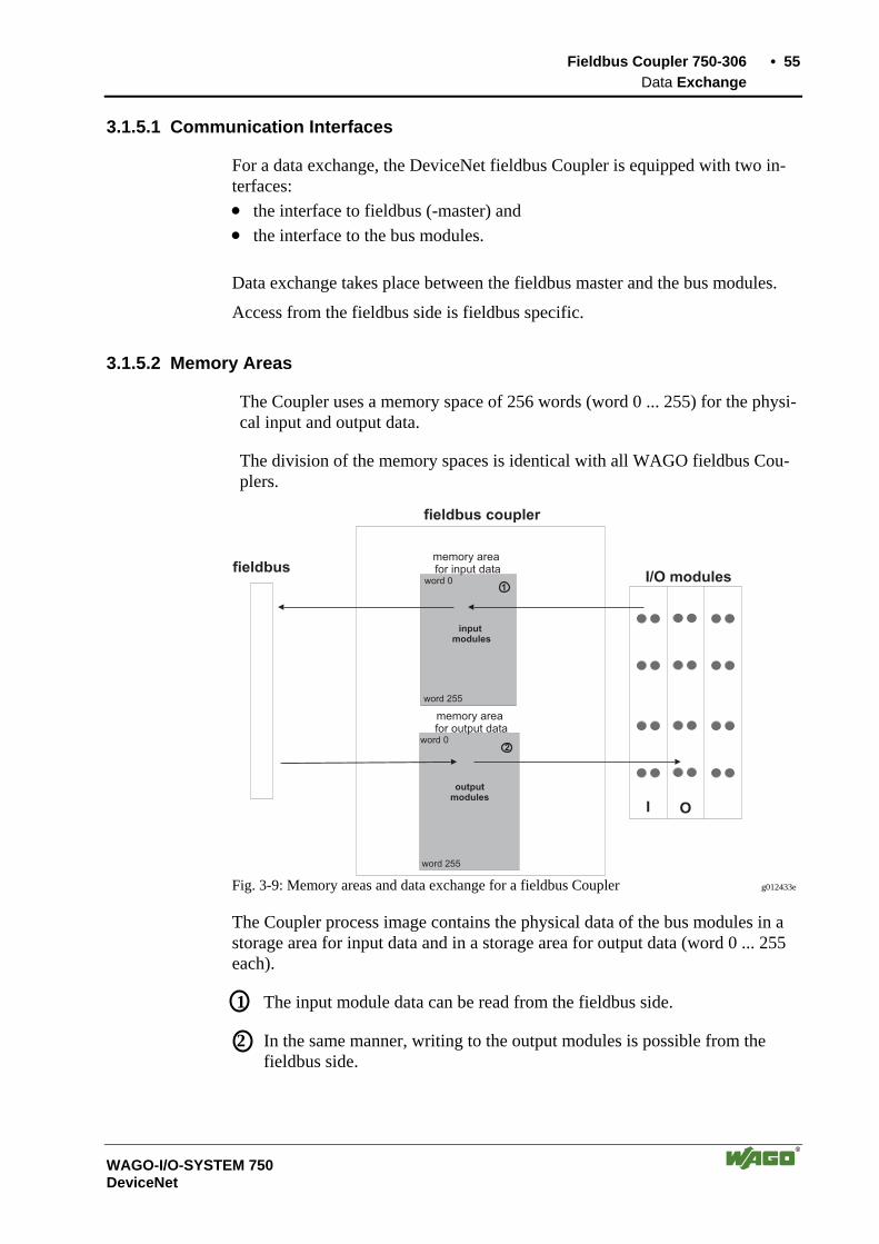
Fieldbus Coupler 750-306 • 55 Data Exchange
WAGO-I/O-SYSTEM 750 DeviceNet
3.1.5.1 Communication Interfaces
For a data exchange, the DeviceNet fieldbus Coupler is equipped with two in-terfaces: • the interface to fieldbus (-master) and • the interface to the bus modules.
Data exchange takes place between the fieldbus master and the bus modules.
Access from the fieldbus side is fieldbus specific.
3.1.5.2 Memory Areas
The Coupler uses a memory space of 256 words (word 0 ... 255) for the physi-cal input and output data.
The division of the memory spaces is identical with all WAGO fieldbus Cou-plers.
I O
1
2
memory areafor input data
I/O modules
inputmodules
word 255
outputmodules
word 0
word 255
word 0
memory areafor output data
fieldbus coupler
fieldbus
Fig. 3-9: Memory areas and data exchange for a fieldbus Coupler g012433e
The Coupler process image contains the physical data of the bus modules in a storage area for input data and in a storage area for output data (word 0 ... 255 each).
1 The input module data can be read from the fieldbus side.
2 In the same manner, writing to the output modules is possible from the fieldbus side.

56 • Fieldbus Coupler 750-306 Data Exchange
WAGO-I/O-SYSTEM 750 DeviceNet
3.1.5.3 Addressing
3.1.5.3.1 Fieldbus Specific
Once the supply voltage is applied, the Assembly Object maps data from the process image. As soon as a connection is established, a DeviceNet-Master (Scanner) can address and access the data by "Class", "Instance" and "Attrib-ute". Data mapping depends on the selected Assembly Instance of the static Assem-bly.
Further information The Assembly Instances of the static Assembly are described in chapter 4.5.1.1 "Assembly Instance".
I O
1
2
ApplicationObject
AssemblyObject
ConnectionObject
Input-Assemly
Output-Assemly
Producer
Consumer
memory areafor input data
I/O modules
inputmodules
word 255
outputmodules
word 0
word 255
fieldbusmaster
word 0
memory areafor output data
Fieldbus coupler
Fig. 3-1: Fieldbus specific data exchange for a DeviceNet fieldbus Coupler g012531e
Note For the number of input and output bits or bytes of the individual I/O modules, please refer to the corresponding I/O module description.
Note A process image restructuring may result if a node is changed or extended. In this case the process data addresses also change in comparison with earlier ones. In the event of adding a module, take the process data of all previous modules into account.
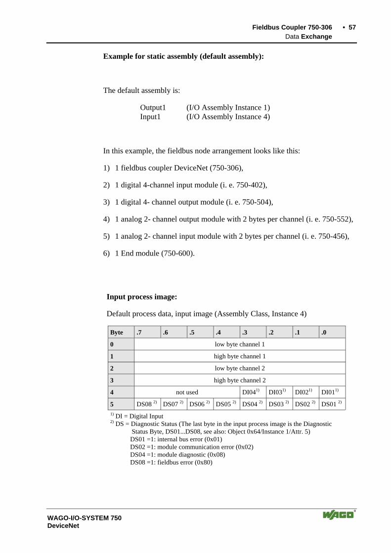
Fieldbus Coupler 750-306 • 57 Data Exchange
WAGO-I/O-SYSTEM 750 DeviceNet
Example for static assembly (default assembly):
The default assembly is:
Output1 (I/O Assembly Instance 1) Input1 (I/O Assembly Instance 4)
In this example, the fieldbus node arrangement looks like this:
1) 1 fieldbus coupler DeviceNet (750-306),
2) 1 digital 4-channel input module (i. e. 750-402),
3) 1 digital 4- channel output module (i. e. 750-504),
4) 1 analog 2- channel output module with 2 bytes per channel (i. e. 750-552),
5) 1 analog 2- channel input module with 2 bytes per channel (i. e. 750-456),
6) 1 End module (750-600).
Input process image:
Default process data, input image (Assembly Class, Instance 4)
Byte .7 .6 .5 .4 .3 .2 .1 .0
0 low byte channel 1
1 high byte channel 1
2 low byte channel 2
3 high byte channel 2
4 not used DI041) DI031) DI021) DI011)
5 DS08 2) DS07 2) DS06 2) DS05 2) DS04 2) DS03 2) DS02 2) DS01 2) 1) DI = Digital Input
2) DS = Diagnostic Status (The last byte in the input process image is the Diagnostic Status Byte, DS01...DS08, see also: Object 0x64/Instance 1/Attr. 5) DS01 =1: internal bus error (0x01) DS02 =1: module communication error (0x02) DS04 =1: module diagnostic (0x08) DS08 =1: fieldbus error (0x80)

58 • Fieldbus Coupler 750-306 Configuration Software
WAGO-I/O-SYSTEM 750 DeviceNet
Output process image:
Default process data, output image (Assembly Class, Instance 1)
Byte .7 .6 .5 .4 .3 .2 .1 .0
0 low byte channel 1
1 high byte channel 1
2 low byte channel 2
3 high byte channel 2
4 not used DO041) DO031) DO021) DO011) 1) DO = Digital Output
3.1.6 Configuration Software
To enable a connection between the PLC and the fieldbus devices, the inter-face modules have to be configured with the individual station data.
To this effect, the scope of delivery of WAGO-I/O-SYSTEM 758 includes the WAGO NETCON software intended for design and configuration, start-up and diagnosis. Further configuration software of different manufacturers include, for in-stance, RSNetWorx.
3.1.7 Starting up DeviceNet Fieldbus Nodes
This chapter shows the step-by-step procedure for starting up a WAGO DeviceNet fieldbus node.
Attention This description is given as an example and is limited to the execution of a local start-up of an individual DeviceNet fieldbus node.
The procedure contains the following steps:
1. Connecting the PC and fieldbus node 2. Setting the MAC ID and baud rate 3. Configuration with static Assembly
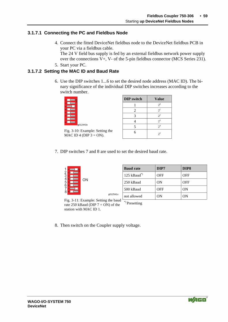
Fieldbus Coupler 750-306 • 59 Starting up DeviceNet Fieldbus Nodes
WAGO-I/O-SYSTEM 750 DeviceNet
3.1.7.1 Connecting the PC and Fieldbus Node
4. Connect the fitted DeviceNet fieldbus node to the DeviceNet fieldbus PCB in your PC via a fieldbus cable. The 24 V field bus supply is fed by an external fieldbus network power supply over the connections V+, V- of the 5-pin fieldbus connector (MCS Series 231).
5. Start your PC. 3.1.7.2 Setting the MAC ID and Baud Rate
6. Use the DIP switches 1...6 to set the desired node address (MAC ID). The bi-nary significance of the individual DIP switches increases according to the switch number.
DIP switch Value 1 20
2 21
3 22
4 23
5 24
12
34
5
ON
67
8
g012443x
Fig. 3-10: Example: Setting the MAC ID 4 (DIP 3 = ON).
6 25
7. DIP switches 7 and 8 are used to set the desired baud rate.
Baud rate DIP7 DIP8
125 kBaud*) OFF OFF
250 kBaud ON OFF
500 kBaud OFF ON
not allowed ON ON
12
34
5
ON
67
8
12345678
ON
g012541x
Fig. 3-11: Example: Setting the baud rate 250 kBaud (DIP 7 = ON) of the station with MAC ID 1.
*) Presetting
8. Then switch on the Coupler supply voltage.
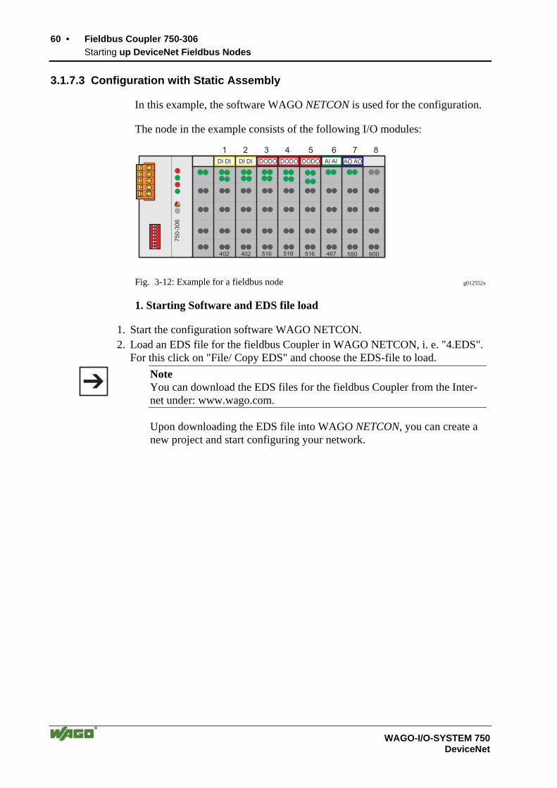
60 • Fieldbus Coupler 750-306 Starting up DeviceNet Fieldbus Nodes
WAGO-I/O-SYSTEM 750 DeviceNet
3.1.7.3 Configuration with Static Assembly
In this example, the software WAGO NETCON is used for the configuration.
The node in the example consists of the following I/O modules:
75
0-3
06
402
DI DI DI DI DODO
402 516 516 516 467 550 600
1 2 3 4 5 6 7 8
DODO DODO AI AI AO AO
Fig. 3-12: Example for a fieldbus node g012552x
1. Starting Software and EDS file load
1. Start the configuration software WAGO NETCON. 2. Load an EDS file for the fieldbus Coupler in WAGO NETCON, i. e. "4.EDS".
For this click on "File/ Copy EDS" and choose the EDS-file to load.
Note You can download the EDS files for the fieldbus Coupler from the Inter-net under: www.wago.com.
Upon downloading the EDS file into WAGO NETCON, you can create a new project and start configuring your network.

Fieldbus Coupler 750-306 • 61 Starting up DeviceNet Fieldbus Nodes
WAGO-I/O-SYSTEM 750 DeviceNet
2. Create a new project
3. Enter the "File" menu and click on menu point "New". 4. Select "DeviceNet" as the fieldbus system and confirm your selection by click-
ing on the "OK" button.
Fig. 3-13: Select fieldbus p112501d
3. Enter Master
5. Enter a fieldbus master on the surface by clicking on the „Master“ menu point in the "Insert" menu. A dialog window opens in which you can select the DeviceNet fieldbus card in your PC.
Fig. 3-14: Select the DeviceNet fieldbus PCB / Insert Master p1x2602d
6. For the DeviceNet Master interface card, click in the left-hand selection win-dow on the corresponding entry to mark it.
7. Take the Master into the right-hand window by clicking on the "Add" button and confirm by clicking on the "OK" button. Now the fieldbus master is shown on the surface as a graphic.

62 • Fieldbus Coupler 750-306 Starting up DeviceNet Fieldbus Nodes
WAGO-I/O-SYSTEM 750 DeviceNet
4. Add a slave
8. Enter a fieldbus slave on the surface by clicking on the “Device” menu point in the "Insert" menu. The mouse pointer changes to the letter D with an arrow.
9. Move this mouse pointer to the graphic display of the fieldbus, then click on the left-hand mouse key. A dialog window opens permitting you to select a DeviceNet device.
Fig. 3-15: Insert slave p012501d
10.For the fieldbus Coupler 750-306 click in the left-hand selection window on the corresponding entry to mark it.
11.Take this into the right-hand window by clicking on the "Add" button and con-firm by clicking on the "OK" button. The configuration is displayed on the surface as a graphic.
Fig. 3-16: Configuration p012502d
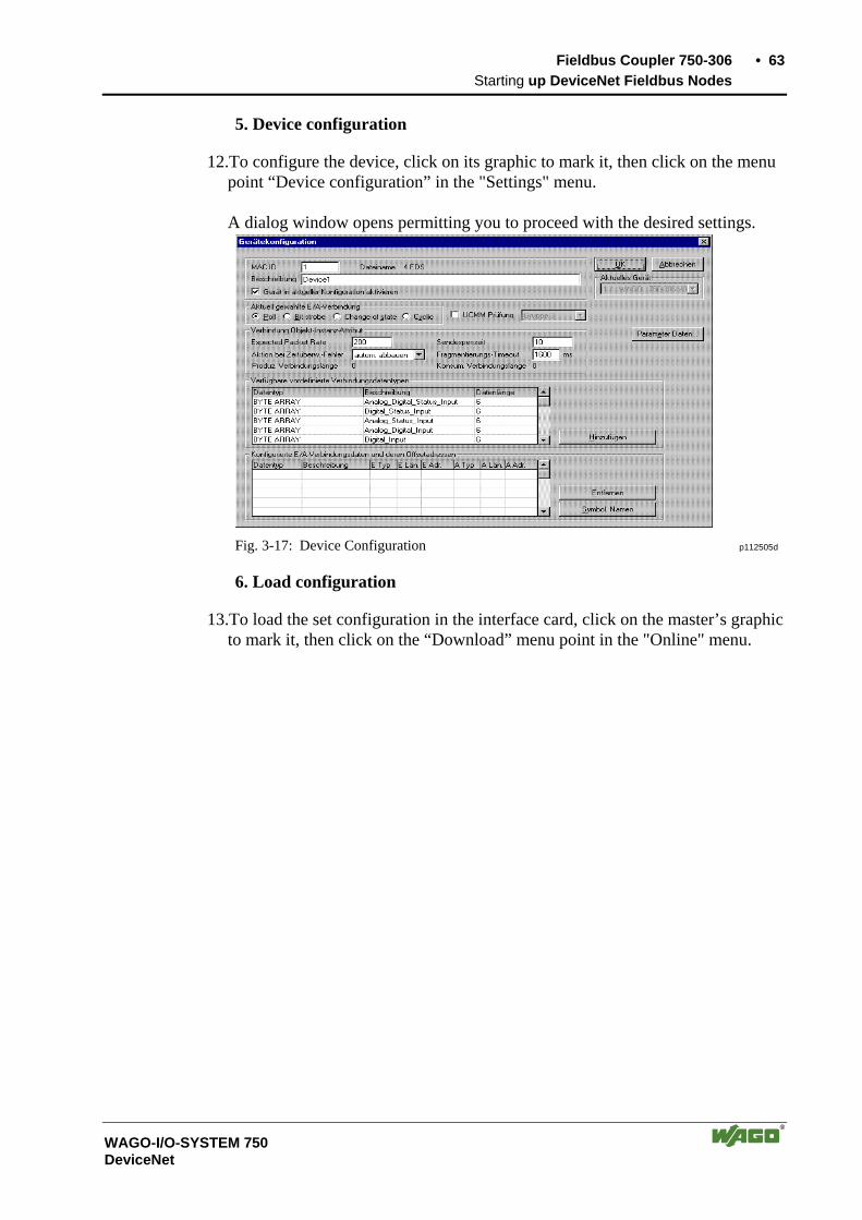
Fieldbus Coupler 750-306 • 63 Starting up DeviceNet Fieldbus Nodes
WAGO-I/O-SYSTEM 750 DeviceNet
5. Device configuration
12.To configure the device, click on its graphic to mark it, then click on the menu point “Device configuration” in the "Settings" menu. A dialog window opens permitting you to proceed with the desired settings.
Fig. 3-17: Device Configuration p112505d
6. Load configuration
13.To load the set configuration in the interface card, click on the master’s graphic to mark it, then click on the “Download” menu point in the "Online" menu.
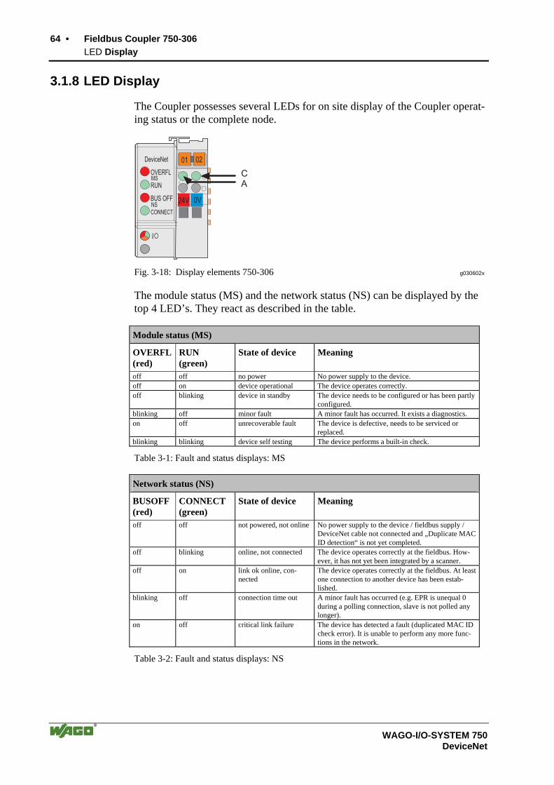
64 • Fieldbus Coupler 750-306 LED Display
WAGO-I/O-SYSTEM 750 DeviceNet
3.1.8 LED Display
The Coupler possesses several LEDs for on site display of the Coupler operat-ing status or the complete node.
24V 0V
01 02
OVERFL
RUN
BUS OFF
DeviceNet
C
DB
A
CONNECTNS
MSCA
I/O
Fig. 3-18: Display elements 750-306 g030602x
The module status (MS) and the network status (NS) can be displayed by the top 4 LED’s. They react as described in the table.
Module status (MS)
OVERFL(red)
RUN (green)
State of device Meaning
off off no power No power supply to the device. off on device operational The device operates correctly. off blinking device in standby The device needs to be configured or has been partly
configured. blinking off minor fault A minor fault has occurred. It exists a diagnostics. on off unrecoverable fault The device is defective, needs to be serviced or
replaced. blinking blinking device self testing The device performs a built-in check.
Table 3-1: Fault and status displays: MS
Network status (NS)
BUSOFF (red)
CONNECT (green)
State of device Meaning
off off not powered, not online No power supply to the device / fieldbus supply / DeviceNet cable not connected and „Duplicate MAC ID detection“ is not yet completed.
off blinking online, not connected The device operates correctly at the fieldbus. How-ever, it has not yet been integrated by a scanner.
off on link ok online, con-nected
The device operates correctly at the fieldbus. At least one connection to another device has been estab-lished.
blinking off connection time out A minor fault has occurred (e.g. EPR is unequal 0 during a polling connection, slave is not polled any longer).
on off critical link failure The device has detected a fault (duplicated MAC ID check error). It is unable to perform any more func-tions in the network.
Table 3-2: Fault and status displays: NS
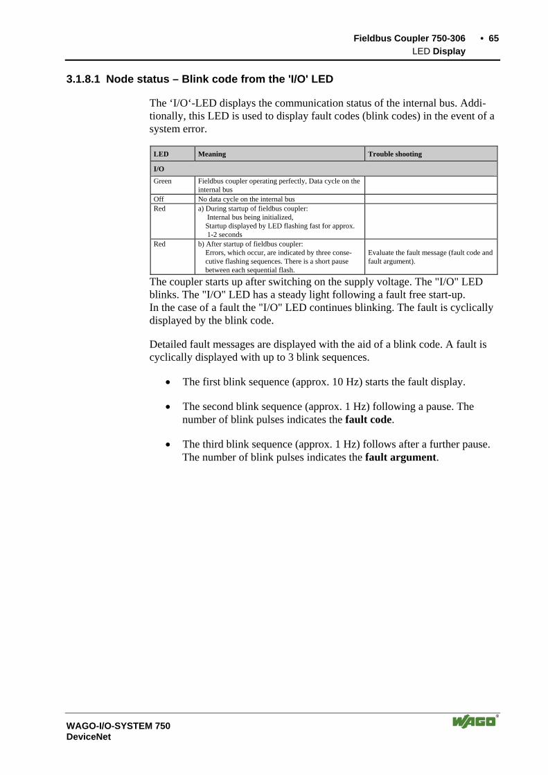
Fieldbus Coupler 750-306 • 65 LED Display
WAGO-I/O-SYSTEM 750 DeviceNet
3.1.8.1 Node status – Blink code from the 'I/O' LED
The ‘I/O‘-LED displays the communication status of the internal bus. Addi-tionally, this LED is used to display fault codes (blink codes) in the event of a system error.
LED Meaning Trouble shooting
I/O Green Fieldbus coupler operating perfectly, Data cycle on the
internal bus
Off No data cycle on the internal bus Red a) During startup of fieldbus coupler:
Internal bus being initialized, Startup displayed by LED flashing fast for approx. 1-2 seconds
Red b) After startup of fieldbus coupler: Errors, which occur, are indicated by three conse- cutive flashing sequences. There is a short pause between each sequential flash.
Evaluate the fault message (fault code and fault argument).
The coupler starts up after switching on the supply voltage. The "I/O" LED blinks. The "I/O" LED has a steady light following a fault free start-up. In the case of a fault the "I/O" LED continues blinking. The fault is cyclically displayed by the blink code.
Detailed fault messages are displayed with the aid of a blink code. A fault is cyclically displayed with up to 3 blink sequences.
• The first blink sequence (approx. 10 Hz) starts the fault display.
• The second blink sequence (approx. 1 Hz) following a pause. The number of blink pulses indicates the fault code.
• The third blink sequence (approx. 1 Hz) follows after a further pause. The number of blink pulses indicates the fault argument.
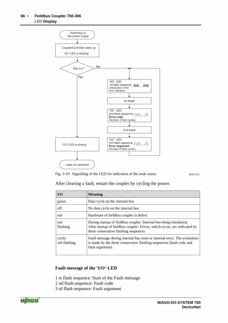
66 • Fieldbus Coupler 750-306 LED Display
WAGO-I/O-SYSTEM 750 DeviceNet
“I/O”-LED is blinking
Test o.k.?No
Yes
“I/O”-LED is shining
ready for operation
2nd break
1st break
“I/O” LED1st flash sequence(Introduction of theerror indication)
“I/O” LED2nd flash sequenceError code(Number of flash cycles)
“I/O” LED3rd flash sequenceError argument(Number of flash cycles)
Coupler/Controller starts up
Switching onthe power supply
Fig. 3-19: Signalling of the LED for indication of the node status g012111e
After clearing a fault, restart the coupler by cycling the power.
I/O Meaning
green Data cycle on the internal bus
off No data cycle on the internal bus
red Hardware of fieldbus coupler is defect
red flashing
During startup of fieldbus coupler: Internal bus being initialized, After startup of fieldbus coupler: Errors, which occur, are indicated by three consecutive flashing sequences
cyclic red flashing
Fault message during internal bus reset or internal error. The evaluation is made by the three consecutive flashing sequences (fault code and fault argument).
Fault message of the ‘I/O‘-LED
1 st flash sequence: Start of the Fault message 2 nd flash sequence: Fault code 3 rd flash sequence: Fault argument
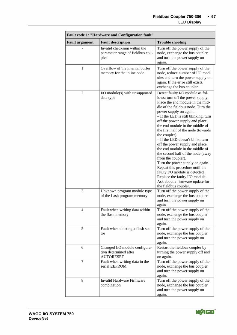
Fieldbus Coupler 750-306 • 67 LED Display
WAGO-I/O-SYSTEM 750 DeviceNet
Fault code 1: "Hardware and Configuration fault"
Fault argument Fault description Trouble shooting - Invalid checksum within the
parameter range of fieldbus cou-pler
Turn off the power supply of the node, exchange the bus coupler and turn the power supply on again.
1 Overflow of the internal buffer memory for the inline code
Turn off the power supply of the node, reduce number of I/O mod-ules and turn the power supply on again. If the error still exists, exchange the bus coupler.
2 I/O module(s) with unsupported data type
Detect faulty I/O module as fol-lows: turn off the power supply. Place the end module in the mid-dle of the fieldbus node. Turn the power supply on again. – If the LED is still blinking, turn off the power supply and place the end module in the middle of the first half of the node (towards the coupler). – If the LED doesn’t blink, turn off the power supply and place the end module in the middle of the second half of the node (away from the coupler). Turn the power supply on again. Repeat this procedure until the faulty I/O module is detected. Replace the faulty I/O module. Ask about a firmware update for the fieldbus coupler.
3 Unknown program module type of the flash program memory
Turn off the power supply of the node, exchange the bus coupler and turn the power supply on again.
4 Fault when writing data within the flash memory
Turn off the power supply of the node, exchange the bus coupler and turn the power supply on again.
5 Fault when deleting a flash sec-tor
Turn off the power supply of the node, exchange the bus coupler and turn the power supply on again.
6 Changed I/O module configura-tion determined after AUTORESET
Restart the fieldbus coupler by turning the power supply off and on again.
7 Fault when writing data in the serial EEPROM
Turn off the power supply of the node, exchange the bus coupler and turn the power supply on again.
8 Invalid Hardware Firmware combination
Turn off the power supply of the node, exchange the bus coupler and turn the power supply on again.

68 • Fieldbus Coupler 750-306 LED Display
WAGO-I/O-SYSTEM 750 DeviceNet
9 Invalid checksum within the serial EEPROM
Turn off the power supply of the node, exchange the bus coupler and turn the power supply on again.
10 serial EEPROM initialization fault
Turn off the power supply of the node, exchange the bus coupler and turn the power supply on again.
11 Fault when reading out data from the EEPROM
Turn off the power supply of the node, exchange the bus coupler and turn the power supply on again.
12 Timeout when writing data in the EEPROM
Turn off the power supply of the node, exchange the bus coupler and turn the power supply on again.
13 - not used - 14 Maximum number of Gateway or
Mailbox I/O modules exceeded Turn off the power supply of the node, reduce number of Gateway or Mailbox I/O modules and turn the power supply on again.
Fault code 2 -not used-
Fault argument Fault description Trouble shooting
- not used -

Fieldbus Coupler 750-306 • 69 LED Display
WAGO-I/O-SYSTEM 750 DeviceNet
Fault code 3: "Internal bus protocol fault"
Fault argument Fault description Trouble shooting
- Internal bus communication malfunction; faulty device can’t be detected
If the fieldbus node comprises internal system supply modules (750-613), make sure first that the power supply of these modules is functioning. This is indicated by the status LEDs. If all I/O modules are connected correctly or if the fieldbus node doesn’t comprise 750-613 modules you can detect the faulty I/O module as follows: turn off the power supply of the node. Place the end module in the middle of the fieldbus node. Turn the power supply on again. – If the LED is still blinking, turn off the power supply and place the end module in the middle of the first half of the node (towards the coupler). – If the LED doesn’t blink, turn off the power supply and place the end module in the middle of the second half of the node (away from the coupler). Turn the power supply on again. Repeat this procedure until the faulty I/O module is detected. Replace the faulty I/O module. If there is only one I/O module left but the LED is still blinking, then this I/O module or the coupler is defective. Replace defective com-ponent.
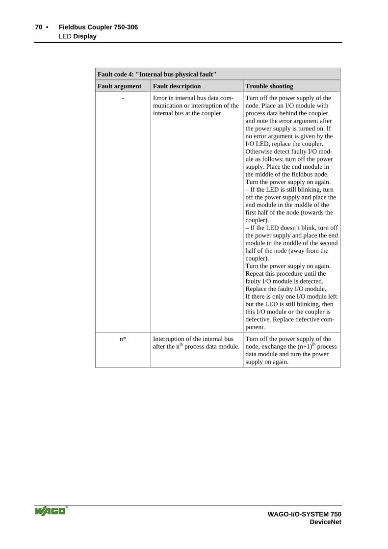
70 • Fieldbus Coupler 750-306 LED Display
WAGO-I/O-SYSTEM 750 DeviceNet
Fault code 4: "Internal bus physical fault"
Fault argument Fault description Trouble shooting
- Error in internal bus data com-munication or interruption of the internal bus at the coupler
Turn off the power supply of the node. Place an I/O module with process data behind the coupler and note the error argument after the power supply is turned on. If no error argument is given by the I/O LED, replace the coupler. Otherwise detect faulty I/O mod-ule as follows: turn off the power supply. Place the end module in the middle of the fieldbus node. Turn the power supply on again. – If the LED is still blinking, turn off the power supply and place the end module in the middle of the first half of the node (towards the coupler). – If the LED doesn’t blink, turn off the power supply and place the end module in the middle of the second half of the node (away from the coupler). Turn the power supply on again. Repeat this procedure until the faulty I/O module is detected. Replace the faulty I/O module. If there is only one I/O module left but the LED is still blinking, then this I/O module or the coupler is defective. Replace defective com-ponent.
n* Interruption of the internal bus after the nth process data module.
Turn off the power supply of the node, exchange the (n+1)th process data module and turn the power supply on again.
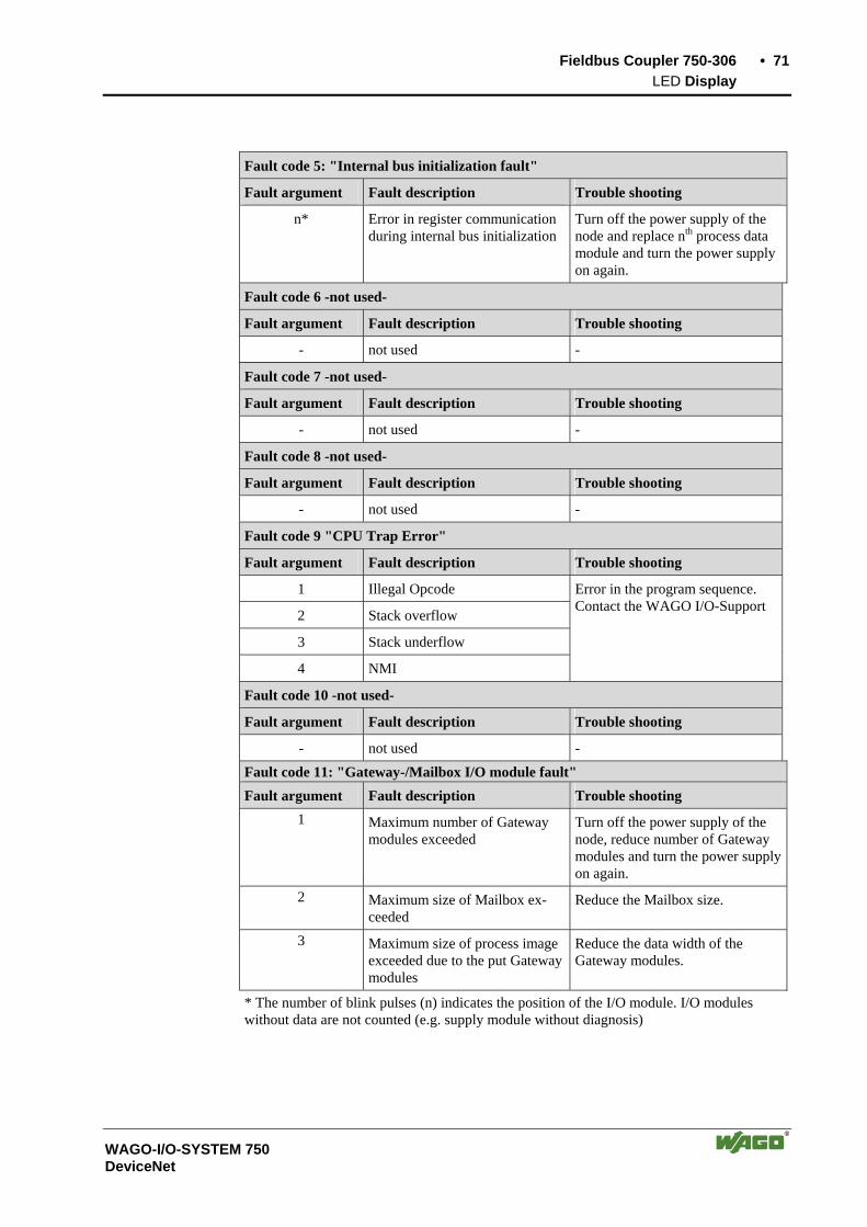
Fieldbus Coupler 750-306 • 71 LED Display
WAGO-I/O-SYSTEM 750 DeviceNet
Fault code 5: "Internal bus initialization fault"
Fault argument Fault description Trouble shooting
n* Error in register communication during internal bus initialization
Turn off the power supply of the node and replace nth process data module and turn the power supply on again.
Fault code 6 -not used-
Fault argument Fault description Trouble shooting
- not used -
Fault code 7 -not used-
Fault argument Fault description Trouble shooting
- not used -
Fault code 8 -not used-
Fault argument Fault description Trouble shooting
- not used -
Fault code 9 "CPU Trap Error"
Fault argument Fault description Trouble shooting
1 Illegal Opcode
2 Stack overflow
3 Stack underflow
4 NMI
Error in the program sequence. Contact the WAGO I/O-Support
Fault code 10 -not used-
Fault argument Fault description Trouble shooting
- not used - Fault code 11: "Gateway-/Mailbox I/O module fault" Fault argument Fault description Trouble shooting
1 Maximum number of Gateway modules exceeded
Turn off the power supply of the node, reduce number of Gateway modules and turn the power supply on again.
2 Maximum size of Mailbox ex-ceeded
Reduce the Mailbox size.
3 Maximum size of process image exceeded due to the put Gateway modules
Reduce the data width of the Gateway modules.
* The number of blink pulses (n) indicates the position of the I/O module. I/O modules without data are not counted (e.g. supply module without diagnosis)
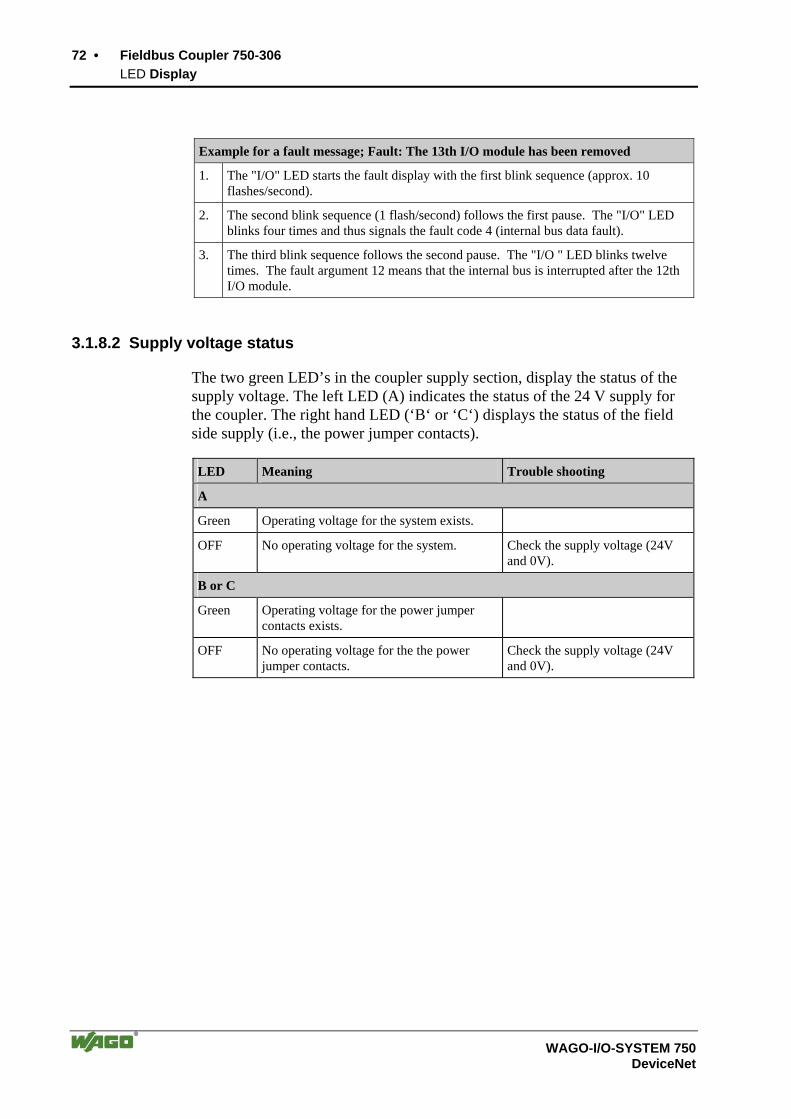
72 • Fieldbus Coupler 750-306 LED Display
WAGO-I/O-SYSTEM 750 DeviceNet
Example for a fault message; Fault: The 13th I/O module has been removed
1. The "I/O" LED starts the fault display with the first blink sequence (approx. 10 flashes/second).
2. The second blink sequence (1 flash/second) follows the first pause. The "I/O" LED blinks four times and thus signals the fault code 4 (internal bus data fault).
3. The third blink sequence follows the second pause. The "I/O " LED blinks twelve times. The fault argument 12 means that the internal bus is interrupted after the 12th I/O module.
3.1.8.2 Supply voltage status
The two green LED’s in the coupler supply section, display the status of the supply voltage. The left LED (A) indicates the status of the 24 V supply for the coupler. The right hand LED (‘B‘ or ‘C‘) displays the status of the field side supply (i.e., the power jumper contacts).
LED Meaning Trouble shooting
A
Green Operating voltage for the system exists.
OFF No operating voltage for the system. Check the supply voltage (24V and 0V).
B or C
Green Operating voltage for the power jumper contacts exists.
OFF No operating voltage for the the power jumper contacts.
Check the supply voltage (24V and 0V).

Fieldbus Coupler 750-306 • 73 Technical Data
WAGO-I/O-SYSTEM 750 DeviceNet
3.1.9 Technical Data
System data
Max. no. of nodes 64 with scanner Max. no. of I/O points ca. 6000 (depends on master) Transmission medium shielded Cu cable,
trunk line: AWG 15, 18 (2x 0.82mm2 +2x1.7mm2)drop line: AWG 22, 24 (2x0.2mm2 +2x0.32mm2)
Max. length of bus line 100 m ... 500 m (depends on baud rate / on the cable)
Baud rate 125 kBaud, 250 kBaud, 500 kBaud BusCoupler connection 5-pole male connector, series 231 (MCS)
female connector 231-305/010-000/050-000 is included
Standards and approvals
UL E175199, UL508 E198726, UL1604 Clas I Div2 ABCD T4A
KEMA 01ATEX1024 X Eex nA II T4
Certification ODVA Conformity marking CE
Accessories
EDS files Download: www.wago.com Miniature WSB quick marking system
Technical data
Max. number of I/O modules 64 Input process image max. 512 bytes Output process image max. 512 bytes Configuration via PC or PLC Voltage supply DC 24 V (-15 % / + 20 %) Current consumption - via power supply terminal - via CAN interface
< 500 mA at 24 V < 120 mA at 11 V
Efficiency of the power supply 87 % Internal power consumption 350 mA at 5 V Total current for I/O modules 1650 mA at 5 V Isolation 500 V system/supply Voltage via power jumper contacts DC 24 V (-15 % / + 20 %) Current via power jumper contactmax DC 10 A Dimensions (mm) W x H x L 51 x 65* x 100 (*from top edge of mounting rail) Weight ca. 195 g EMC interference resistance acc. EN 50082-2 (96) EMC interference transmission acc. EN 50081-2 (94)

74 • Fieldbus Controller 750-806 Description
WAGO-I/O-SYSTEM 750 DeviceNet
3.2 Fieldbus Controller 750-806
3.2.1 Description
The programmable fieldbus Controller 750-806 (short: PFC) combines the DeviceNet functions of the fieldbus Coupler 750-306 with that of a program-mable logic control (PLC).
The application program is created with WAGO-I/O-PRO 32 in accordance with IEC 61131-3.
All input signals of the sensors are grouped in the Controller.
According to the IEC 61131-3 programming, data processing occurs locally in the PFC. The link results created in this manner can be put out directly to the actuators or transmitted to the higher ranking control system via the bus.
The programmer has access to all fieldbus and I/O data.
In the initialization phase, the fieldbus Controller determines the physical structure of the node and creates a process image from this with all inputs and outputs. This could involve a mixed arrangement of analog (word by word data exchange) and digital (byte by byte data exchange) modules.
The local process image is subdivided into an input and output data area.
The data of the analog modules are mapped into the PDOs according to the order of their position downstream of the bus Coupler. The bits of the digital modules are compiled to form bytes and also mapped into PDOs. Should the number of digital I/Os exceed 8 bits, the Coupler automatically starts another byte.
In addition to the functions of the fieldbus Coupler, the fieldbus Controller supports the following DeviceNet functions:
• Create Connection via UCMM-Port
• Offline Connection Set
• DeviceNet Shutdown
• Dynamic assembly
• Change MAC ID by SW
• Heartbeat
• Bit-Strobe
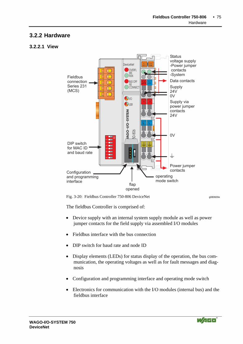
Fieldbus Controller 750-806 • 75 Hardware
WAGO-I/O-SYSTEM 750 DeviceNet
3.2.2 Hardware
3.2.2.1 View
24V 0V
+ +
Ñ Ñ
01 02
750-
806
OVERFL
RUN
BUS OFF
I/O
USR
DeviceNet
C
DB
A
CONNECTNS
12
34
56
78
ON
MS
Supply24V0V
0V
Power jumpercontacts
Statusvoltage supply-Power jumpercontacts-System
Supply viapower jumpercontacts24V
Data contactsFieldbusconnectionSeries 231(MCS)
Configurationand programminginterface
DIP switchfor MAC IDand baud rate
flapopened
operatingmode switch
Fig. 3-20: Fieldbus Controller 750-806 DeviceNet g080600e
The fieldbus Controller is comprised of:
• Device supply with an internal system supply module as well as power jumper contacts for the field supply via assembled I/O modules
• Fieldbus interface with the bus connection
• DIP switch for baud rate and node ID
• Display elements (LEDs) for status display of the operation, the bus com-munication, the operating voltages as well as for fault messages and diag-nosis
• Configuration and programming interface and operating mode switch
• Electronics for communication with the I/O modules (internal bus) and the fieldbus interface

76 • Fieldbus Controller 750-806 Hardware
WAGO-I/O-SYSTEM 750 DeviceNet
3.2.2.2 Device Supply
The voltage supply is fed in via the terminals with the CAGE CLAMP® con-nection. Device supply is intended for system supply and field side supply.
24 V
10 nF
10 nF24 V
5 V
0 V
1 / 2
3 / 4
2) 10nF/500V
1) 1M
1) 2)
24 V
5 V
750-806
1 2 3 4
24 V 0 V
Electronic
I/O Modules
FieldbusInterface
Fie
ldb
us
Inte
rface
Ele
ctr
on
ic
Fig. 3-21: Device supply g080601e
The integrated internal system supply module generates the necessary voltage to supply the electronics and the connected I/O modules.
The fieldbus interface is supplied with electrically isolated voltage from the internal system supply module.

Fieldbus Controller 750-806 • 77 Hardware
WAGO-I/O-SYSTEM 750 DeviceNet
3.2.2.3 Fieldbus Connection
The scope of delivery includes the plug connector 231-305/010-000/050-000 from the WAGO MULTI CONNECTION SYSTEM. The connector has gold plated contacts and has the signal designations printed at it clamping units.
The connection diagram shows the table, the colours resulting in accordance with the DeviceNet specification and are identical to the conductor colours of the DeviceNet cables.
Pin Signal Code Description
5 V+ red 11 ... 25 V
4 CAN_H white CAN Signal High
3 Shield Shield connection
2 CAN_L blue CAN Signal Low
FieldbusconnectionSeries 231(MCS)
CAN_High
drain
CAN_Low
V-
V+
1 V- black 0 V
Fig. 3-22: Fieldbus connection, MCS g012500e
For the connection of small conductor cross sections, we recommend to insert an insulation stop from series 231-670 (white), 231-671 (light grey) or 231-672 (dark grey) due to the low kink resistance. This insulation stop prevents a conductor from kinking when it hits the conductor contact point, and as such, the conductor insulation from being also entered into and clamped in the con-nection point. Connector marking, housing components, test connectors in-cluding cables and heater connectors for cable extensions, are available.
The connection point is lowered in such a way that after a connector is in-serted, installation in an 80 mm high switchbox is possible.
The electrical isolation between the fieldbus system and the electronics is made via the DC/DC converter and the optocoupler in the fieldbus.

78 • Fieldbus Controller 750-806 Hardware
WAGO-I/O-SYSTEM 750 DeviceNet
3.2.2.4 Display Elements
The operating condition of the fieldbus controller or node is signalled via light diodes (LED).
Four LED’s, specific for DeviceNet (OVERFL, RUN, BUSOFF, CONNECT), indicate the module status (MS) or the network status (NS).
24V 24V0V 0V
+ ++ +
OVERFL
RUN
BUS OFF
DeviceNet
C C
D DB B
A A
CONNECT
I/OI/O I/OI/O
DeviceNet
MS
NS
OVERFL
RUN
BUS OFF
CONNECT
MS
NS
USR USR
C A
A B
Fig. 3-23: Display elements 750-806 g012556x
LED Color Meaning
OVERFL red Errors or faults at the fieldbus Coupler.
RUN green Fieldbus Coupler is ready for operation.
BUS OFF red Error or malfunction at network
CONNECT green Fieldbus Coupler is ready for network communication.
IO red /green / orange
The 'I/O'-LED indicates the operation of the node and signals faults encountered.
USR red /green / orange
The 'USR' LED can be selected by a user program in a programma-ble fieldbus Controller
A green Status of the operating voltage system
B or C green Status of the operating voltage – power jumper contacts (LED position is manufacturing dependent)

Fieldbus Controller 750-806 • 79 Hardware
WAGO-I/O-SYSTEM 750 DeviceNet
3.2.2.5 Configuration and Programming Interface
The configuration and programming interface is located behind the cover flap. This is used to communicate with WAGO-I/O-CHECK and WAGO-I/O-PRO 32 as well as for firmware transfer.
Configuration andprogramming interface
openflap
Fig. 3-24: Configuration and programming interface g01xx07e
The communication cable (750-920) is connected to the 4-pole header.
Warning The communication cable 750-920 must not be connected or disconnected while the coupler/controller is powered on!
3.2.2.6 Operating Mode Switch
The operating mode switch is located behind the cover flap beside the con-figuration and programming interface.
Update firmware
Run Stop Reset(pushing down)
openflap
mode switch Fig. 3-25: Operating mode switch g01xx10e
The switch is a push/slide switch with 3 settings and a hold-to-run function.
80 • Fieldbus Controller 750-806 Hardware
WAGO-I/O-SYSTEM 750 DeviceNet
Operating mode switch Function
From middle to top position Activate program processing (RUN)
From top to middle position Stop program processing (STOP)
Lower position, bootstrap For original loading of firmware, not necessary for user
Push down (i.e.with a screwdriver)
Hardware reset All outputs are reset; variables are set to 0 or to FALSE or to an initial value.
The hardware reset can be performed with STOP as well as RUN in any position of the operating mode switch!
An operating mode is internally changed at the end of a PLC cycle.
Attention If outputs are set when switching over the operating mode switch from RUN to STOP, they remain set! Switching off the software side i.e. by initiators, are ineffective, because the program is no longer processed.
Note With "GET_STOP_VALUE" (library "System.lib") WAGO-I/O-PRO 32 provides a function which serves to recognize the last cycle prior to a pro-gram stop giving the user the possibility to program the behavior of the Con-troller in case of a STOP. With the aid of this function the Controller outputs can be switched to a safe condition.
3.2.2.7 Hardware Address (MAC ID)
The DIP switch is used both for parametrizing (setting the baud rate) of the fieldbus controller and for setting the MAC ID.
The MAC-ID (node address) is set with the DIP switches 1 to 6 by 'sliding' the desired DIP switch to 'ON'. The binary significance of the individual DIP switches increases according to the switch number. DIP switch 1 being the lowest bit with the value 20 and switch 6 the highest bit with the value 25. Therefore the MAC ID 1 is set with DIP1 = ON, the MAC ID 8 with DIP4 = ON, etc.
For the DeviceNet fieldbus nodes the node address can be set within the range from 0 to 63.
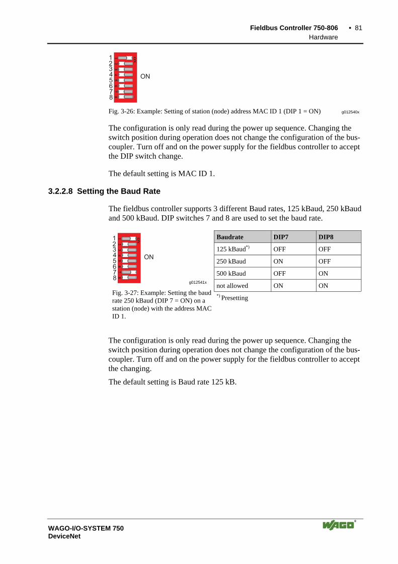
Fieldbus Controller 750-806 • 81 Hardware
WAGO-I/O-SYSTEM 750 DeviceNet
12
34
5
ON
67
8
12345678
ON
Fig. 3-26: Example: Setting of station (node) address MAC ID 1 (DIP 1 = ON) g012540x
The configuration is only read during the power up sequence. Changing the switch position during operation does not change the configuration of the bus-coupler. Turn off and on the power supply for the fieldbus controller to accept the DIP switch change.
The default setting is MAC ID 1.
3.2.2.8 Setting the Baud Rate
The fieldbus controller supports 3 different Baud rates, 125 kBaud, 250 kBaud and 500 kBaud. DIP switches 7 and 8 are used to set the baud rate.
Baudrate DIP7 DIP8
125 kBaud*) OFF OFF
250 kBaud ON OFF
500 kBaud OFF ON
not allowed ON ON 1
23
45
ON
67
8
12345678
ON
g012541x
Fig. 3-27: Example: Setting the baud rate 250 kBaud (DIP 7 = ON) on a station (node) with the address MAC ID 1.
*) Presetting
The configuration is only read during the power up sequence. Changing the switch position during operation does not change the configuration of the bus-coupler. Turn off and on the power supply for the fieldbus controller to accept the changing.
The default setting is Baud rate 125 kB.

82 • Fieldbus Controller 750-806 Operating System
WAGO-I/O-SYSTEM 750 DeviceNet
3.2.3 Operating System
3.2.3.1 Start-up
The Controller starts-up after switching on the supply voltage or after a hard-ware reset. The PLC program in the flash memory is transferred to the RAM.
This is followed by the initialization of the system. The Controller determines the I/O modules and the present configuration. The variables are set to 0 or to FALSE or to an initialization value given by the PLC program. The flags re-tain their status. The "I/O" LED blinks red during this phase.
Following an error free start-up, the Controller changes over to the "RUN" mode. The "I/O" LED lights up green.
A PLC program does not yet exist in the flash memory when delivered. The Controller start-up is described without initializing the system. It then behaves as a Coupler.
3.2.3.2 PLC Cycle
The PLC cycle starts following an error free start-up when the operating mode switch is in the top position or by a start command from the WAGO-I/O-PRO 32. The input and output data of the fieldbus and the I/O modules as well as the times are read. Subsequently, the PLC program in the RAM is processed followed by the output data of the fieldbus and the I/O modules in the process image. Operating system functions, amongst others, for diagnosis and communication are performed and the times are updated at the end of the PLC cycle. The cycle starts again with the reading in of the input and output data and the times.
The change of the operating mode (STOP/RUN) is made at the end of a PLC cycle.
The cycle time is the time from the start of the PLC program to the next start. If a loop is programmed within a PLC program, the PLC running time and thus the PLC cycle are extended correspondingly.
The inputs, outputs and times are not updated during the processing of the PLC program. This update occurs in a defined manner only at the end of the PLC program. For this reason it is not possible to wait for an event from the process or the elapse of a time within a loop.
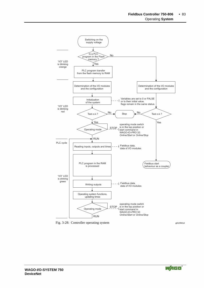
Fieldbus Controller 750-806 • 83 Operating System
WAGO-I/O-SYSTEM 750 DeviceNet
Variables are set to 0 or FALSEor to their initial value,flags remain in the same status.
Switching on thesupply voltage
Initializationof the system
Reading inputs, outputs and times
Writing outputsFieldbus data,data of I/O modules
Operating system functions,updating times
Is a PLCprogram in the Flash
memory ?
No
Yes
PLC program transferfrom the flash memory to RAM
Determination of the I/O modulesand the configuration
Test o.k.?
Yes
NoStop Test o.k.?
No
Determination of the I/O modulesand the configuration
STOPOperating mode
Operating modeSTOP
RUN
RUN
Fieldbus data,data of I/O modules
Yes
Fieldbus startbehaviour as a coupler
operating mode switchis in the top position orstart command inWAGO-IO- 32:
orPRO
Online/Start Online/Stop
operating mode switchis in the top position orstart command inWAGO-IO- 32:
orPRO
Online/Start Online/Stop
“I/O” LEDis blinking
orange
“I/O” LEDis blinking
red
PLC cycle
“I/O” LEDis shining
green
PLC program in the RAMis processed
Fig. 3-28: Controller operating system g012941d
84 • Fieldbus Controller 750-806 Process Image
WAGO-I/O-SYSTEM 750 DeviceNet
3.2.4 Process Image
After switching on, the Controller recognizes all I/O modules plugged into the node which supply or wait for data (data width/bit width > 0). In nodes, analog and digital I/O modules can be mixed.
The Controller produces an internal process image from the data width and the type of I/O module as well as the position of the I/O modules in the node. It is divided into an input and an output data area.
The data of the digital I/O modules is bit orientated, i.e. the data exchange is made bit for bit. The analog I/O modules are all byte orientated I/O modules, i.e. those where the data exchange is made byte for byte. These I/O modules include, for example, the counter modules, I/O modules for angle and path measurement as well as the communication modules.
Note For the number of input and output bits or bytes of the individually activated on I/O modules please refer to the corresponding I/O module description.
The data of the I/O modules is separated from the local input and output proc-ess image in the sequence of their position after the controller in the individual process image. In the respective I/O area, first of all analog modules are mapped, then all digital modules, even if the order of the connected analog and digital modules does not comply with this order. The digital channels are grouped, each of these groups having a data width of 1 byte. Should the number of digital I/Os exceed 8 bits, the Controller automatically starts another byte.
Note A process image restructuring may result if a node is changed or extended. In this case, the process data addresses also change in comparison with earlier ones. In the event of adding modules, take the process data of all previous modules into account.
The process image for the physical bus module data is identical with that of the WAGO DeviceNet fieldbus Coupler. With the Controller, the data of the PFC variables are filled into the process image, separated according to input and output data.
Fieldbus Controller 750-806 • 85 Data Exchange
WAGO-I/O-SYSTEM 750 DeviceNet
3.2.5 Data Exchange
With DeviceNet, the transmission and exchange of data is made using objects.
For a network access on the single objects, it is necessary to create a connec-tion between the desired participants and to allocate connection objects.
The DeviceNet fieldbus Controller 750-806 can communicate via the UCMM-Port (Unconnected Message Manager Port). The UCMM-Port permits a dynamic connection via one or several connec-tions from one or more clients.
The object configuration for the data transmission is defined by the Assembly Object. The Assembly Object can be used to group data (e.g.: I/O data) to form blocks (mapping) and send this data via one single communication con-nection. This mapping results in a reduced number of accesses to the network. A differentiation is made between input and output assemblies. An Input Assembly reads data from the application via the network or pro-duces data on the network respectively. An Output Assembly writes data to the application or consumes data from the network respectively.
Various Assembly instances are permanently programmed (static assembly) in the fieldbus Controller.
Further information The Assembly instances for the static Assembly are described in chapter 4.5.1.1 "Assembly Instance".
In addition to the static assembly, dynamic assembly can also be used with the fieldbus Controller. The dynamic assembly can be used to set up Assembly In-stances in which process data from various application objects can be config-ured as required.
Further information For information regarding the dynamic Assembly, please refer to chapter 3.2.7.4 "Dynamic Assembly".
86 • Fieldbus Controller 750-806 Data Exchange
WAGO-I/O-SYSTEM 750 DeviceNet
3.2.5.1 Communication Interfaces
For a data exchange, the DeviceNet fieldbus Controller is equipped with three interfaces: • the interface to fieldbus (-master), • the PLC functionality of the PFC (CPU) and • the interface to the bus modules
Data exchange takes place between the fieldbus master and the bus modules, between the PLC functionality of the PFC (CPU) and the bus modules as well as between the fieldbus master and the PLC functionality of the PFC (CPU).
Data access of the PLC functionality of the PFC (CPU) is via an application re-lated IEC 61131-3 program and independent on the fieldbus system.
Access from the fieldbus side is fieldbus specific.
3.2.5.2 Memory Areas
The Controller uses a memory space of 256 words (word 0 ... 255) for the physical input and output data. The Controller is assigned an additional memory space for mapping the PFC variables defined according to IEC 61131-3. This extended memory space (word 256 ... 511 each) is used to map the PFC variables behind the physical process image.
The division of the memory spaces and the access of the PLC functionality (CPU) to the process data is identical with all WAGO fieldbus Controllers. Access is via an application related IEC 61131-3 program and independent on the fieldbus system.
Access from the fieldbus side is fieldbus specific.
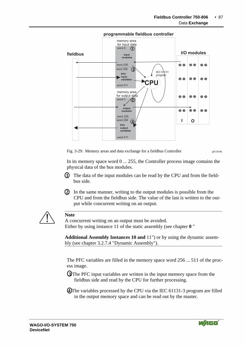
Fieldbus Controller 750-806 • 87 Data Exchange
WAGO-I/O-SYSTEM 750 DeviceNet
CPU
I O
1
3
1
3
2
4
memory areafor input data
I/O modulesinput
modules
word 255
outputmodules
word 0
word 255
word 0
memory areafor output data
programmable fieldbus controller
IEC 61131programPFC
inputvariables
PFCoutputvariables
word 256
word 511
word 511
word 256
fieldbus
Fig. 3-29: Memory areas and data exchange for a fieldbus Controller g012434d
In its memory space word 0 ... 255, the Controller process image contains the physical data of the bus modules.
1 The data of the input modules can be read by the CPU and from the field-bus side.
2 In the same manner, writing to the output modules is possible from the CPU and from the fieldbus side. The value of the last is written to the out-put while concurrent writing on an output.
Note A concurrent writing on an output must be avoided. Either by using instance 11 of the static assembly (see chapter 0 "
Additional Assembly Instances 10 and 11") or by using the dynamic assem-bly (see chapter 3.2.7.4 "Dynamic Assembly").
The PFC variables are filled in the memory space word 256 ... 511 of the proc-ess image.
3 The PFC input variables are written in the input memory space from the fieldbus side and read by the CPU for further processing.
4 The variables processed by the CPU via the IEC 61131-3 program are filled in the output memory space and can be read out by the master.

88 • Fieldbus Controller 750-806 Data Exchange
WAGO-I/O-SYSTEM 750 DeviceNet
In addition, the Controller offers further memory spaces which, however, can-not be accessed from the fieldbus side:
RAM The RAM memory is used to create variables not required for com-munication with the interfaces but for internal processing, such as computation of results.
The retain memory is a non-volatile memory, i.e. all values are re-tained following a voltage failure. The memory management is auto-matic. In this memory area, flags for the IEC 61131-3 program are filed together with variables without memory space addressing or variables which are explicitly defined with "var retain".
Retain
Note The automatic memory management can cause a data overlap. For this reason, we recommend not to use a mix of flags and retain vari-ables.
Code memory
The IEC 61131-3 program is filed in the code memory. The code memory is a flash ROM. Once the supply voltage is applied, the pro-gram is transmitted from the flash to the RAM memory. After an error-free start-up, the PFC cycle starts when the operating mode switch is turned to its upper position or by a start command from WAGO-I/O-PRO 32.
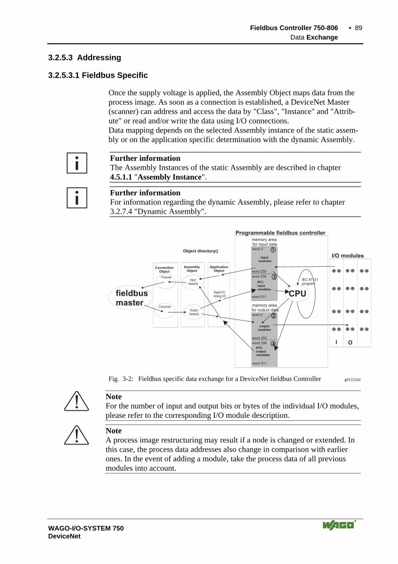
Fieldbus Controller 750-806 • 89 Data Exchange
WAGO-I/O-SYSTEM 750 DeviceNet
3.2.5.3 Addressing
3.2.5.3.1 Fieldbus Specific
Once the supply voltage is applied, the Assembly Object maps data from the process image. As soon as a connection is established, a DeviceNet Master (scanner) can address and access the data by "Class", "Instance" and "Attrib-ute" or read and/or write the data using I/O connections. Data mapping depends on the selected Assembly instance of the static assem-bly or on the application specific determination with the dynamic Assembly.
Further information The Assembly Instances of the static Assembly are described in chapter 4.5.1.1 "Assembly Instance".
Further information For information regarding the dynamic Assembly, please refer to chapter 3.2.7.4 "Dynamic Assembly".
CPU
I O
1
3
1
3
2
4
Digital I/O,Analog I/O
ApplicationObject
AssemblyObject
ConnectionObject
Input-Assemly
Output-Assemly
Producer
Consumer
memory areafor input data
I/O modulesinputmodules
word 255
outputmodules
word 0
word 255
fieldbusmaster
word 0
memory areafor output data
Programmable fieldbus controller
Object directory()
IEC 61131programPFC
inputvariables
PFCoutputvariables
word 256
word 511
word 511
word 256
Fig. 3-2: Fieldbus specific data exchange for a DeviceNet fieldbus Controller g012532d
Note For the number of input and output bits or bytes of the individual I/O modules, please refer to the corresponding I/O module description.
Note A process image restructuring may result if a node is changed or extended. In this case, the process data addresses also change in comparison with earlier ones. In the event of adding a module, take the process data of all previous modules into account.

90 • Fieldbus Controller 750-806 Data Exchange
WAGO-I/O-SYSTEM 750 DeviceNet
Example for static assembly (default assembly): The default assembly is:
Output1 (I/O Assembly Instance 1) Input1 (I/O Assembly Instance 4)
In this example, the fieldbus node arrangement looks like this: 1) 1 fieldbus Controller DeviceNet (750-806) 2) 1 digital 4-channel input module (i. e. 750-402), 3) 1 digital 4- channel output module (z. B. 750-504), 4) 1 analog 2- channel output module with 2 bytes per channel (i. e. 750-552), 5) 1 analog 2- channel input module with 2 bytes per channel (i. e. 750-456), 6) 1 End module (750-600). Input process image:
Default process data, input image (Assembly Class, Instance 4)
Byte .7 .6 .5 .4 .3 .2 .1 .0
0 low byte channel 1
1 high byte channel 1
2 low byte channel 2
3 high byte channel 2
4 not used DI041) DI031) DI021) DI011)
5 DS08 2) DS07 2) DS06 2) DS05 2) DS04 2) DS03 2) DS02 2) DS01 2) 1) DI = Digital Input
2) DS = Diagnostic Status (The last byte in the input process image is the Diagnostic Status Byte, DS01...DS08, see also: Object 0x64/Instance 1/Attr. 5) DS01 =1: internal bus error (0x01) DS02 =1: module communication error (0x02) DS04 =1: module diagnostic (0x08) DS08 =1: fieldbus error (0x80)
Output process image:
Default process data, output image (Assembly Class, Instance 1)
Byte .7 .6 .5 .4 .3 .2 .1 .0
0 low byte channel 1
1 high byte channel 1
2 low byte channel 2
3 high byte channel 2
4 not used DO041) DO031) DO021) DO011) 1) DO = Digital Output
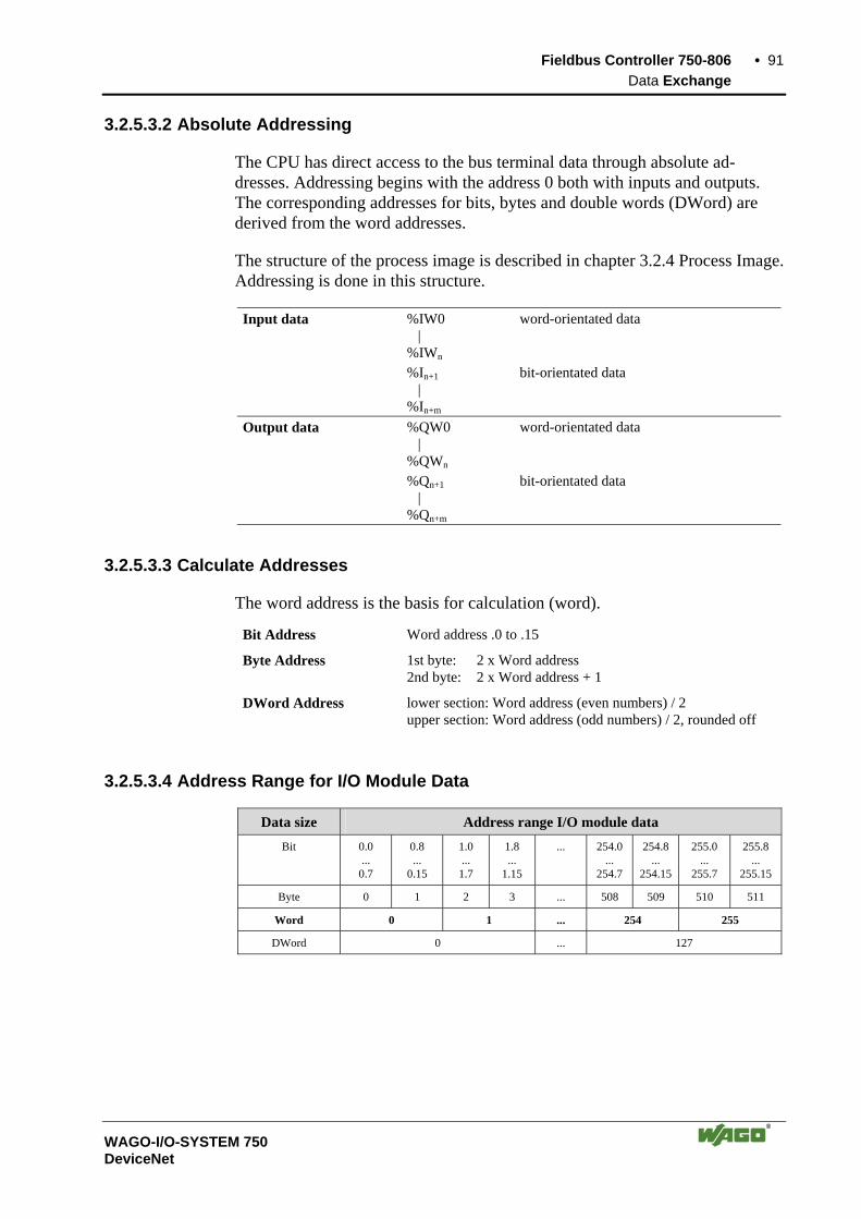
Fieldbus Controller 750-806 • 91 Data Exchange
WAGO-I/O-SYSTEM 750 DeviceNet
3.2.5.3.2 Absolute Addressing
The CPU has direct access to the bus terminal data through absolute ad-dresses. Addressing begins with the address 0 both with inputs and outputs. The corresponding addresses for bits, bytes and double words (DWord) are derived from the word addresses.
The structure of the process image is described in chapter 3.2.4 Process Image. Addressing is done in this structure.
Input data %IW0 | %IWn
word-orientated data
%In+1 | %In+m
bit-orientated data
Output data %QW0 | %QWn
word-orientated data
%Qn+1 | %Qn+m
bit-orientated data
3.2.5.3.3 Calculate Addresses
The word address is the basis for calculation (word).
Bit Address Word address .0 to .15
Byte Address 1st byte: 2 x Word address 2nd byte: 2 x Word address + 1
DWord Address lower section: Word address (even numbers) / 2 upper section: Word address (odd numbers) / 2, rounded off
3.2.5.3.4 Address Range for I/O Module Data
Data size Address range I/O module data Bit 0.0
... 0.7
0.8 ...
0.15
1.0 ...
1.7
1.8 ...
1.15
... 254.0 ...
254.7
254.8 ...
254.15
255.0 ...
255.7
255.8 ...
255.15
Byte 0 1 2 3 ... 508 509 510 511
Word 0 1 ... 254 255
DWord 0 ... 127
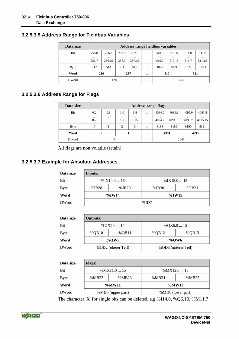
92 • Fieldbus Controller 750-806 Data Exchange
WAGO-I/O-SYSTEM 750 DeviceNet
3.2.5.3.5 Address Range for Fieldbus Variables
Data size Address range fieldbus variables Bit 256.0
... 256.7
256.8 ...
256.15
257.0...
257.7
257.8...
257.15
... 510.0 ...
510.7
510.8 ...
510.15
511.0 ...
511.7
511.8 ...
511.15
Byte 512 513 514 515 ... 1020 1021 1022 1023
Word 256 257 ... 510 511
DWord 128 ... 255
3.2.5.3.6 Address Range for Flags
Data size Address range flags Bit 0.0
... 0.7
0.8 ...
0.15
1.0 ...
1.7
1.8 ...
1.15
... 4094.0...
4094.7
4094.8 ...
4094.15
4095.0 ...
4095.7
4095.8...
4095.15
Byte 0 1 2 3 ... 8188 8189 8190 8191
Word 0 1 ... 4094 4095
DWord 0 ... 2047
All flags are non volatile (retain).
3.2.5.3.7 Example for Absolute Addresses
Data size Inputs:
Bit %IX14.0 ... 15 %IX15.0 ... 15
Byte %IB28 %IB29 %IB30 %IB31
Word %IW14 %IW15
DWord %ID7
Data size Outputs:
Bit %QX5.0 ... 15 %QX6.0 ... 15
Byte %QB10 %QB11 %QB12 %QB13
Word %QW5 %QW6
DWord %QD2 (oberer Teil) %QD3 (unterer Teil)
Data size Flags:
Bit %MX11.0 ... 15 %MX12.0 ... 15
Byte %MB22 %MB23 %MB24 %MB25
Word %MW11 %MW12
DWord %MD5 (upper part) %MD6 (lower part)
The character 'X' for single bits can be deleted, e.g.%I14.0, %Q6.10, %M11.7

Fieldbus Controller 750-806 • 93 Programming the PFC with WAGO-I/O-PRO 32
WAGO-I/O-SYSTEM 750 DeviceNet
3.2.6 Programming the PFC with WAGO-I/O-PRO 32
Due to the IEC 61131 programming of the DeviceNet fieldbus Controller 750-806 you have the option to use the functionality of a PLC beyond the functions of fieldbus Coupler 750-306. An application program according to IEC 61131-3 is created using the pro-gramming tool WAGO-I/O-PRO 32 (order No.: 759-332/000-002).
This manual, however, does not include a description of how to program with WAGO-I/O-PRO 32. In contrast, the following chapters are to describe the special modules for WAGO-I/O-PRO 32 for you to utilize explicitly for pro-gramming the DeviceNet fieldbus Controller. The description also explains transmitting the IEC 61131-3 program into the Controller and loading a suitable communication driver.
More information For a detailed description of how to use the software, please refer to the WAGO-I/O-PRO 32 manual (order No.: 759-122 / 000-002).
3.2.6.1 WAGO-I/O-PRO 32 Library Elements
You are offered various libraries for different IEC 61131-3 programming ap-plications in WAGO-I/O-PRO 32. They contain modules for universal use and can, thereby, facilitate and speed up the creation of your program. As standard, the library 'standard.lib' is available to you.
The library described in the following is specifically intended for DeviceNet projects with WAGO-I/O-PRO 32:
• "DevNet. lib"
This library extends the fieldbus Controller 750-806 by the master function. As a result, it can be programmed in the network as a DeviceNet Master.
Several libraries are loaded on the WAGO-I/O-PRO CD. Having integrated this library, you have access to its POUs, data types and global variables which can be used in the same manner as those defined by yourself.
More information For a detailed description of the POUs and the software operation, please refer to the WAGO-I/O-PRO 32 manual (order No.: 759-122 / 000-002).
94 • Fieldbus Controller 750-806 Programming the PFC with WAGO-I/O-PRO 32
WAGO-I/O-SYSTEM 750 DeviceNet
3.2.6.2 IEC 61131-3 Program Transfer
Program transfer from the PC to the Controller following programming of the desired IEC 61131 application can be made in two different ways:
• via the serial interface or
• via the fieldbus.
One suitable communication driver each is required for both types.
More information For information on the installation of the communication drivers as well as details regarding the use of the software, please refer to the WAGO-I/O-PRO 32 manual (order No.: 759-122 / 000-002).
3.2.6.2.1 Transmission via the Serial Interface
Use the WAGO communication cable to produce a physical connection via the serial interface. This is contained in the scope of delivery of the programming tool IEC 61131-3, order No.: 759-332/000-002, or can be purchased as an ac-cessory under order No.: 750-920. Connect the COMX port of your PC with the communication interface of your Controller via the WAGO communication cable.
Warning The communication cable 750-920 must not be connected or disconnected while the coupler/controller is powered on!
A communication driver is required for serial data transmission. In WAGO-I/O-PRO 32, this driver and its parameters are entered in the "Communica-tion parameters" dialog.
1. Start the WAGO-I/O-PRO 32 software via ’Start/Programs’ or by double clicking on the WAGO-I/O-PRO-32 symbol on your desk top.
2. In the "Online" menu click on the "Communication parameters" menu point. The dialog "Communication parameters" opens. The basic setting of this dialog has not yet any entries.
3. In the selection window mark the desired driver on the right-hand dialog side (i.e. "Serial RS232"), to configure the serial connection between PC and the Controller).
4. In the center window of the dialog, the following entries have to appear: - Parity: Even - Stop bits: 1

Fieldbus Controller 750-806 • 95 Programming the PFC with WAGO-I/O-PRO 32
WAGO-I/O-SYSTEM 750 DeviceNet
If necessary, change the entries accordingly. You can now commence testing the Controller.
Note To be able to access the Controller, ensure that the operating mode switch of the Controller is set to the center or the top position.
5. Under "Online" click on the "Log-on" menu point to log into the Control-ler. (The WAGO-I/O-PRO 32 server is active during online operation. The communication parameters cannot be polled.)
6. If there is not a program in the Controller, a window appears asking whether or not the program is to be loaded. Confirm with "Yes". Subsequently the current program will be loaded.
7. As soon as the program is loaded, you can start program via the "Online" menu, menu point "Start". At the right-hand end of the status bar, the system signals "ONLINE RUNNING"."
8. To terminate the online operation, return via the "Online" menu and click on the "Log-off" menu point.
3.2.6.2.2 Transmission via the Fieldbus
The field bus cable is the physical connection between the PC and the Con-troller. It is necessary to have a suitable communication driver for data trans-mission. This driver and how it is parametered is entered in WAGO-I/O-PRO 32 in the "communication parameter" dialog.
Note Transmission via the fieldbus is supported by UCMM. Here, for the down-load of the PFC program, WAGO-I/O-PRO 32 counts as a subscriber.
1. Start the WAGO-I/O-PRO 32 software via ’Start/Programs’ or by double clicking on the WAGO-I/O-PRO-32 symbol on your desk top.
2. In the "Online" menu click on the "Communication parameters" menu point. The "Communication parameters" dialog opens.
3. Click on the “New” button to define a driver in the "Communication pa-rameter" dialog
4. Enter any name and mark the driver "Hilscher PA Interface standard" in the selection window of the dialog. Subsequently confirm with "OK".

96 • Fieldbus Controller 750-806 Programming the PFC with WAGO-I/O-PRO 32
WAGO-I/O-SYSTEM 750 DeviceNet
5. If necessary, change the entry accordingly in the center window of the dia-log.
Note Prerequisite for the access to the Controller is that the operating mode switch of the Controller is in the center or top position.
6. Under "Online" click on the "Log-on" menu point to log into the Control-ler. (During online operation, the WAGO-I/O-PRO 32 server is active. The communication parameters cannot be polled.)
7. If there is not a program contained in the Controller, a window appears ask-ing whether or not the program is to be loaded. Confirm with "Yes". Subsequently the current program is loaded.
8. As soon as the program is loaded, you can start the program via the "On-line" menu, menu point "Start". At the right-hand end of the status bar, the system signals "ONLINE RUNNING".
9. To terminate the online operation, return via the "Online" menu and click on the "Log-off" menu point.
Fieldbus Controller 750-806 • 97 Special DeviceNet Features of the Controller
WAGO-I/O-SYSTEM 750 DeviceNet
3.2.7 Special DeviceNet Features of the Controller
3.2.7.1 Connection via the UCMM port
In contrast to the fieldbus Coupler 750-306 as a Group 2 Only Server, the De-viceNet Controller supports the dynamic connection via the UCMM port (Un-connected Message Manager Port). For the Controller, the simultaneous set-up of 5 explicit and 5 dynamic I/O connections, i.e. the connection with 5 subscribers, is possible.
3.2.7.2 Offline Connection Set
Due to the Offline Connection Set, the fieldbus node can be addressed via the network when this node has been switched off because of a double MAC ID and is in a Communication Fault status. After being addressed, the MAC ID of the fieldbus Controller can be changed using the software.
3.2.7.3 DeviceNet Shutdown
The Device Shutdown allows the fieldbus node to log out from a control in a defined manner if the node is switched off due to internal faults. This function can be used in a targeted way in DeviceNet networks subject to very high safety requirements, such as e.g. in the chemical industry or in semi-conductor production.
3.2.7.4 Dynamic Assembly
An Assembly Object is used to group data (e.g. I/O data) to form blocks to be sent as a single message. The static Assembly allows the user to access per-manently pre-programmed Assembly Instances in the fieldbus Controller. The dynamic Assembly, on the other hand, offers the possibility to set up Assem-bly Instances in which process data from various application objects can be configured as required. In addition to the I/O data transmission, the dynamic assembly can also be used for a targeted selection of data which are to be transmitted explicitly via the fieldbus, or those which are explicitly not to be transmitted via the field-bus.
Attention To set the pysical outputs with the PFC either use the dynamic assembly or the instance 11 of the static assemblies. With this, you do not enter the physi-cal outputs into the mapping in order to prevent the output data from being transmitted and temporary overwritten by the fieldbus.
Further information You can find more details in chapter 4.6.2.2.2 "Dynamic Assembly".

98 • Fieldbus Controller 750-806 Special DeviceNet Features of the Controller
WAGO-I/O-SYSTEM 750 DeviceNet
3.2.7.5 Change MAC ID by SW
The MAC ID of the Controller can be changed via the network using the soft-ware (e.g. WAGO NETCON, RS NetWorx). For this purpose, the node ad-dress is stored in non-volatile memory. Should the address set at the DIP switch differ from the one set via the network using the software, the I/O LED changes its colour to orange. To reset the software default address, the invalid address 64 is entered in class 3, instance 1, attribute 1. Subsequently, the Controller has its MAC ID that is set at the DIP switch.
3.2.7.6 Heartbeat
The heartbeat function permits a node to cyclically transmit a so-called heart-beat message and, in this manner, to signal its communication ability to all members in the network.
If a responsible heartbeat consumer does not receive a message within a pre-defined time (Heartbeat Consuming Time), this is registered as a heartbeat fault. The relationship between producer and consumer of a Heartbeat-message can be configured by entries in the object directory, so the time be-tween two Heartbeat messages can be entered in Class 0x01, Instance 1, At-tribut ID 10 (0x0A).
3.2.7.7 Bit-Strobe
The bit strobe I/O connection is always a 1 to n multicast connection. In other words, a master can reach with its message all slaves supporting the bit strobe command. The transfer takes place at the same time. In this manner it is possible to synchronize the slaves. The length of this master message is limited to 8 bytes. Each node address in the net is assigned a bit within the 8 data bytes. The reaction of the slave which bit is set is specific to the application. The reaction has to be defined and it has to be known by the PLC. With its answer, each slave can return 8 bytes of data. The order of the answers depends on the reaction time of the single slave and, in addition, it depends on the particular node address. If all slaves would reply to the Bit-Strobe command at the same time, the order of sending on the CAN bus would be determined by the node address (bit arbitra-tion).
Further information You can find more details in chapter 4.6.2.2.1 "Bit-Strobe".

Fieldbus Controller 750-806 • 99 Configuration Software
WAGO-I/O-SYSTEM 750 DeviceNet
3.2.8 Configuration Software
To allow a connection between the PLC and the fieldbus devices, the interface modules have to be configured with the individual station file.
To this effect, the scope of the WAGO-I/O-SYSTEM 758 includes the WAGO NETCON software intended for design and configuration, start-up and diagnosis. Further configuration software of different manufacturers include, for in-stance, RSNetWorx.
3.2.9 Starting-up DeviceNet Fieldbus Nodes
This chapter shows the step-by-step procedure for starting up a WAGO DeviceNet fieldbus node. Following this will be information for programming the PFC with WAGO-I/O-PRO 32.
Attention This description is given as an example and is limited to the execution of a local start-up of an individual DeviceNet fieldbus node.
The procedure contains the following steps: 14.Connecting the PC and fieldbus node 15.Setting the MAC ID and baud rate 16.Configuration with static and dynamic Assembly
3.2.9.1 Connecting the PC and Fieldbus Node
1. Connect the assembled DeviceNet fieldbus node to the DeviceNet fieldbus PCB in your PC via a fieldbus cable and start your PC. The 24 V field bus supply is fed by an external fieldbus network power supply over the con-nections V+, V- of the 5-pin fieldbus connector (MCS Series 231).
2. Start your PC.
3.2.9.2 Setting the MAC ID and Baud Rate
1. Use the DIP switches 1...6 to set the desired node address (MAC ID). The binary significance of the individual DIP switches increases according to the switch number.
DIP switch Value 1 20
2 21
3 22
4 23
5 24
12
34
5
ON
67
8
g012443x Fig. 3-30 Example: Setting the MAC ID 4 (DIP 3 = ON). 6 25
DIP switches 7 and 8 are used to set the desired baud rate.
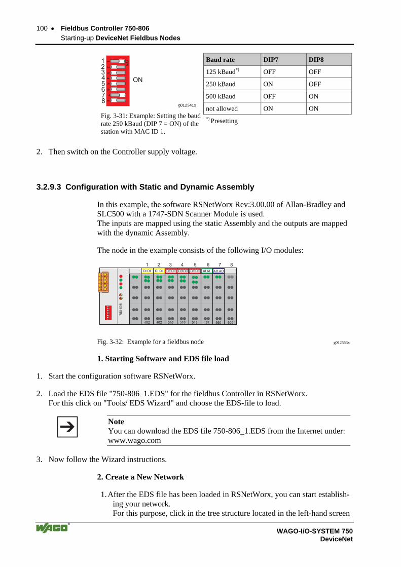
100 • Fieldbus Controller 750-806 Starting-up DeviceNet Fieldbus Nodes
WAGO-I/O-SYSTEM 750 DeviceNet
Baud rate DIP7 DIP8
125 kBaud*) OFF OFF
250 kBaud ON OFF
500 kBaud OFF ON
not allowed ON ON
12
34
5
ON
67
8
12345678
ON
g012541x
Fig. 3-31: Example: Setting the baud rate 250 kBaud (DIP 7 = ON) of the station with MAC ID 1.
*) Presetting
2. Then switch on the Controller supply voltage.
3.2.9.3 Configuration with Static and Dynamic Assembly
In this example, the software RSNetWorx Rev:3.00.00 of Allan-Bradley and SLC500 with a 1747-SDN Scanner Module is used. The inputs are mapped using the static Assembly and the outputs are mapped with the dynamic Assembly.
The node in the example consists of the following I/O modules:
75
0-8
06
402
DI DI DI DI DODO
402 516 516 516 467 550 600
1 2 3 4 5 6 7 8
DODO DODO AI AI AO AO
Fig. 3-32: Example for a fieldbus node g012553x
1. Starting Software and EDS file load
1. Start the configuration software RSNetWorx.
2. Load the EDS file "750-806_1.EDS" for the fieldbus Controller in RSNetWorx. For this click on "Tools/ EDS Wizard" and choose the EDS-file to load.
Note You can download the EDS file 750-806_1.EDS from the Internet under: www.wago.com
3. Now follow the Wizard instructions.
2. Create a New Network
1. After the EDS file has been loaded in RSNetWorx, you can start establish-ing your network. For this purpose, click in the tree structure located in the left-hand screen
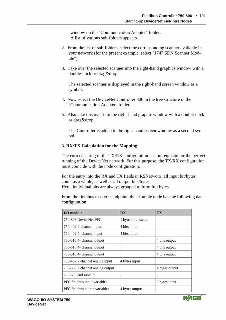
Fieldbus Controller 750-806 • 101 Starting-up DeviceNet Fieldbus Nodes
WAGO-I/O-SYSTEM 750 DeviceNet
window on the "Communication Adapter" folder. A list of various sub-folders appears.
2. From the list of sub-folders, select the corresponding scanner available in your network (for the present example, select "1747 SDN Scanner Mod-ule").
3. Take over the selected scanner into the right-hand graphics window with a double-click or drag&drop. The selected scanner is displayed in the right-hand screen window as a symbol.
4. Now select the DeviceNet Controller 806 in the tree structure in the "Communication Adapter" folder.
5. Also take this over into the right-hand graphic window with a double-click or drag&drop. The Controller is added to the right-hand screen window as a second sym-bol.
3. RX/TX Calculation for the Mapping
The correct setting of the TX/RX configuration is a prerequisite for the perfect running of the DeviceNet network. For this purpose, the TX/RX configuration must coincide with the node configuration.
For the entry into the RX and TX fields in RSNetworx, all input bit/bytes count as a whole, as well as all output bits/bytes. Here, individual bits are always grouped to form full bytes.
From the fieldbus master standpoint, the example node has the following data configuration:
I/O module RX TX
750-806 DeviceNet PFC 1 byte input status
750-402 4-channel input 4 bits input
750-402 4- channel input 4 bits input
750-516 4- channel output 4 bits output
750-516 4- channel output 4 bits output
750-516 4- channel output 4 bits output
750-467 2 channel analog input 4 bytes input
750-550 2 channel analog output 4 bytes output
750-600 end module - -
PFC fieldbus input variables 0 bytes input
PFC fieldbus output variables 4 bytes output

102 • Fieldbus Controller 750-806 Starting-up DeviceNet Fieldbus Nodes
WAGO-I/O-SYSTEM 750 DeviceNet
Sum 10 bytes 6 bytes
Note PFC output variables are defined from the point of view of the programmable fieldbus Controller. These are input variables from the point of view of the fieldbus DeviceNet, which are added to the RX Settings. Accordingly, PFC input variables are output variables for IEC 61131-3 access of the field bus. For that reason they will be added to the TX Settings: IEC 61131-3 input variable = PFC output variable PFC input variable = IEC 61131-3 output variable
Programmablefieldbus controller
PFCinputvariables
PFCoutputvariables
PLCoutputvariables
fieldbus
PLCinputvariables
Fig. 3-33: Zusammenhang SPS-Variablen and PFC-Variablen g012444d
4. Static assembly for inputs
In the present example, the master/scanner is to have access to the physical in-puts and to the 4 bytes PFC output variables. The number of input data is complemented by 4 bytes of the PFC output vari-ables during the static assembly for the TX configuration of the scanner.
1. To be able to parameterize the Controller, double-click on the graphic symbol of the fieldbus node 750-806.
2. In the "General" register, you can assign the Controller any desired ad-dress. To this effect, click in the input window for the address and enter the ad-dress in accordance with the address set at the Controller DIP switch.
Fieldbus Controller 750-806 • 103 Starting-up DeviceNet Fieldbus Nodes
WAGO-I/O-SYSTEM 750 DeviceNet
3. The RX/TX configuration can be entered in the "Parameters" register. For this purpose, move to the "Groups" dialog box, down along the scroll bar, and select "PLC fieldbus variables".
4. Do not change the value for the ID#37 "PLC fieldbus Input variables" which is 0. Enter 4 for the ID#38 "PLC fieldbus Output variables".
5. Confirm the setting by clicking on the "OK" button.
6. Double-click on the scanner icon to start the configuration. The dialog window "1797-SDN Scanner Module" opens.
7. Select the "Scanlist" register card.
8. Click on the button with the arrow to the right in order to take over the DeviceNet Controller 750-806 in the left-hand window "Available De-vices" into the "Scanlist" window.
9. Click on the "Edit I/O Parameters..." button.
10. Activate the poll function by clicking on the field located in front of "Polled". The field is now ticked which permits the entry for TX and RX.
11. Enter 6 bytes in the "TX-Size" dialog box. They are receipt bytes for the inputs. Enter 4 bytes for the PFC input variables in the "RX-Size" dialog box. The number of these bytes results from the following determinations in the dy-namic assembly for the outputs. This simultaneously defines that only the PFC input variables and no physical outputs are to be written by the mas-ter.
12. Then click on the "OK" button to take over the parameters. A window appears indicating that several I/O data will not be mapped. Confirm the question of whether or not you wish to continue by clicking on the "Yes" button.
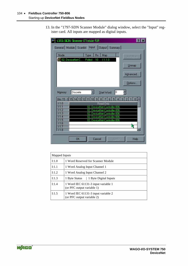
104 • Fieldbus Controller 750-806 Starting-up DeviceNet Fieldbus Nodes
WAGO-I/O-SYSTEM 750 DeviceNet
13. In the "1797-SDN Scanner Module" dialog window, select the "Input" reg-ister card. All inputs are mapped as digital inputs.
Mapped Inputs
I:1.0 1 Word Reserved for Scanner Module
I:1.1 1 Word Analog Input Channel 1
I:1.2 1 Word Analog Input Channel 2
I:1.3 1 Byte Status | 1 Byte Digital Inputs
I:1.4 1 Word IEC 61131-3 input variable 1 (or PFC output variable 1)
I:1.5 1 Word IEC 61131-3 input variable 2 (or PFC output variable 2)
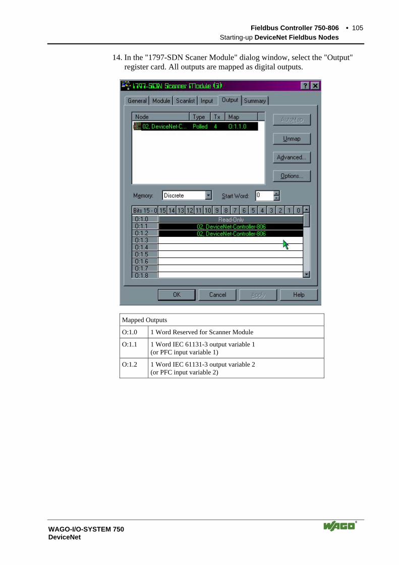
Fieldbus Controller 750-806 • 105 Starting-up DeviceNet Fieldbus Nodes
WAGO-I/O-SYSTEM 750 DeviceNet
14. In the "1797-SDN Scaner Module" dialog window, select the "Output" register card. All outputs are mapped as digital outputs.
Mapped Outputs
O:1.0 1 Word Reserved for Scanner Module
O:1.1 1 Word IEC 61131-3 output variable 1 (or PFC input variable 1)
O:1.2 1 Word IEC 61131-3 output variable 2 (or PFC input variable 2)

106 • Fieldbus Controller 750-806 Starting-up DeviceNet Fieldbus Nodes
WAGO-I/O-SYSTEM 750 DeviceNet
5. Dynamic assembly for the outputs
The dynamic assembly is used to map those data which are to be transmitted via the fieldbus. They are stored as classes, instances and attributes.
17.In the graphical display, click on the symbol of the fieldbus Controller 750-806 so that the symbol is marked.
18.Then click on the “Class Instance Editor...” menu point in the "Device" menu.
A window displaying a warning appears:
Note This editor changes parameters in the Controller. For this reason, ensure that all data is entered consistently either as hexadeci-mal or decimal. If the data number format is not consistent, data loss can result up to a total functional failure of the Controller.
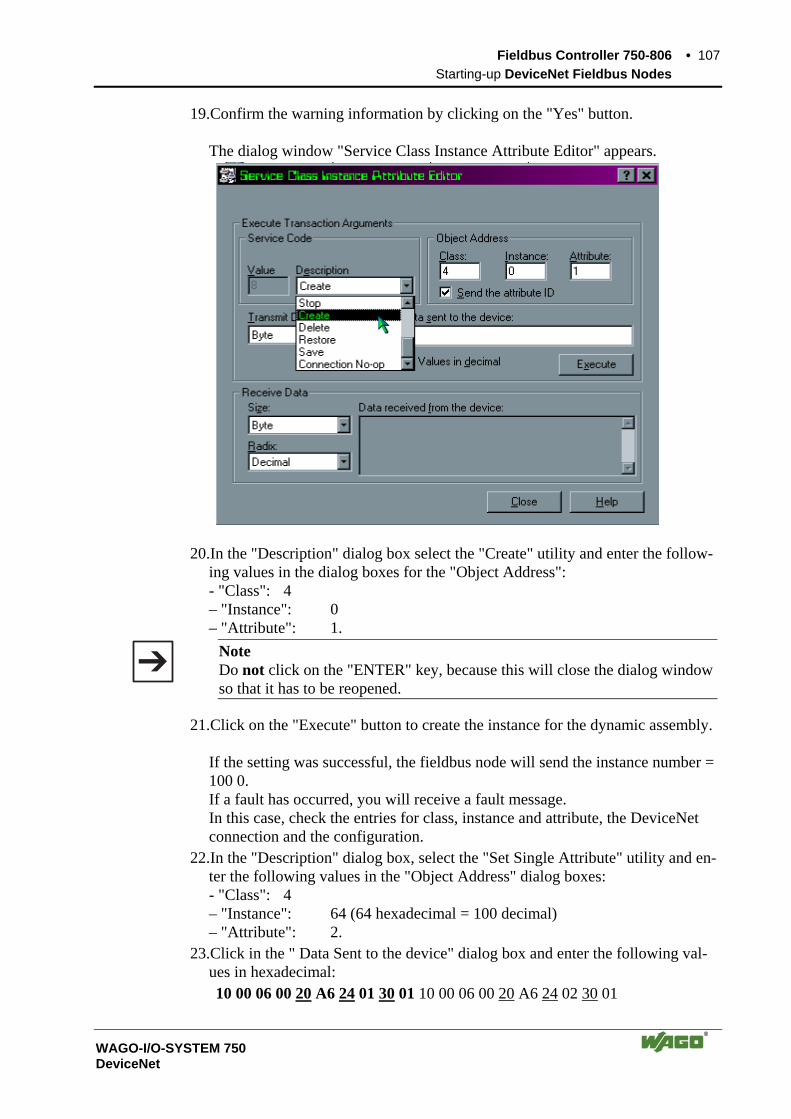
Fieldbus Controller 750-806 • 107 Starting-up DeviceNet Fieldbus Nodes
WAGO-I/O-SYSTEM 750 DeviceNet
19.Confirm the warning information by clicking on the "Yes" button. The dialog window "Service Class Instance Attribute Editor" appears.
20.In the "Description" dialog box select the "Create" utility and enter the follow-ing values in the dialog boxes for the "Object Address": - "Class": 4 – "Instance": 0 – "Attribute": 1.
Note Do not click on the "ENTER" key, because this will close the dialog window so that it has to be reopened.
21.Click on the "Execute" button to create the instance for the dynamic assembly. If the setting was successful, the fieldbus node will send the instance number = 100 0. If a fault has occurred, you will receive a fault message. In this case, check the entries for class, instance and attribute, the DeviceNet connection and the configuration.
22.In the "Description" dialog box, select the "Set Single Attribute" utility and en-ter the following values in the "Object Address" dialog boxes: - "Class": 4 – "Instance": 64 (64 hexadecimal = 100 decimal) – "Attribute": 2.
23.Click in the " Data Sent to the device" dialog box and enter the following val-ues in hexadecimal: 10 00 06 00 20 A6 24 01 30 01 10 00 06 00 20 A6 24 02 30 01

108 • Fieldbus Controller 750-806 Starting-up DeviceNet Fieldbus Nodes
WAGO-I/O-SYSTEM 750 DeviceNet
The path is described by: 0x20 CC (Class) 0x24 II (Instance) 0x30 AA (Attribute)
24.Click on the "Execute" button to define the mapping. If the mapping was successful, the fieldbus node sends a “performance” con-firmation. If a fault has occurred, you will receive a fault message. In the event of a communication or reply fault, check the DeviceNet connection and whether or not the instance was correctly set.
25.Click on the "Close" button. The dialog window is closed.
26.To parameterize the Controllers, double-click on the graphic symbol of the fieldbus node 750-806.
27.Select the "Parameters" register and “All parameters” in the "Groups" dialog box.

Fieldbus Controller 750-806 • 109 Starting-up DeviceNet Fieldbus Nodes
WAGO-I/O-SYSTEM 750 DeviceNet
1. Use the scroll bar to move down to the ID#13 and #ID14 addresses. ID#13 is a pointer for the inputs (Default = 4). This parameter is changed when the inputs are mapped for the master. This is not required due to the fact that the inputs are only read and not written.
ID#14 is a pointer for the outputs (Default = 1). This parameter is changed in order to point on the dynamic mapping of the outputs that are mapped in the dynamic assembly instance 100dec. (0x64hex).
2. Do not change the pre-set standard value 4 of the ID#13. Enter 25604 decimal for the ID#14 to direct the pointer on the dynamic assembly output mapping.

110 • Fieldbus Controller 750-806 Starting-up DeviceNet Fieldbus Nodes
WAGO-I/O-SYSTEM 750 DeviceNet
The value 25604 corresponds to the hexadecimal writing 0x6404. 04 (Low Byte) = Class type 64 (High Byte) = 100 decimal instance number
3. Change the value for the ID#39. Select "Dynamic created instances are stored in non volatile memory", to retain the storage of the configuration for the Dynamic Assembly even follow-ing a voltage failure of the Controller.
4. To take over the pre-set parameters into the Controller, select the following parameter in the right-hand control box in the "Parameters" register: "All Values", then click on the "Download parameters to the device" symbol which is located on the far right next to the dialog box.
5. Confirm the setting by clicking on the "OK" button. The dialog window is closed.
6. Then switch the supply voltage of the Controller off and on again. Now the fieldbus node is ready for networked communication.
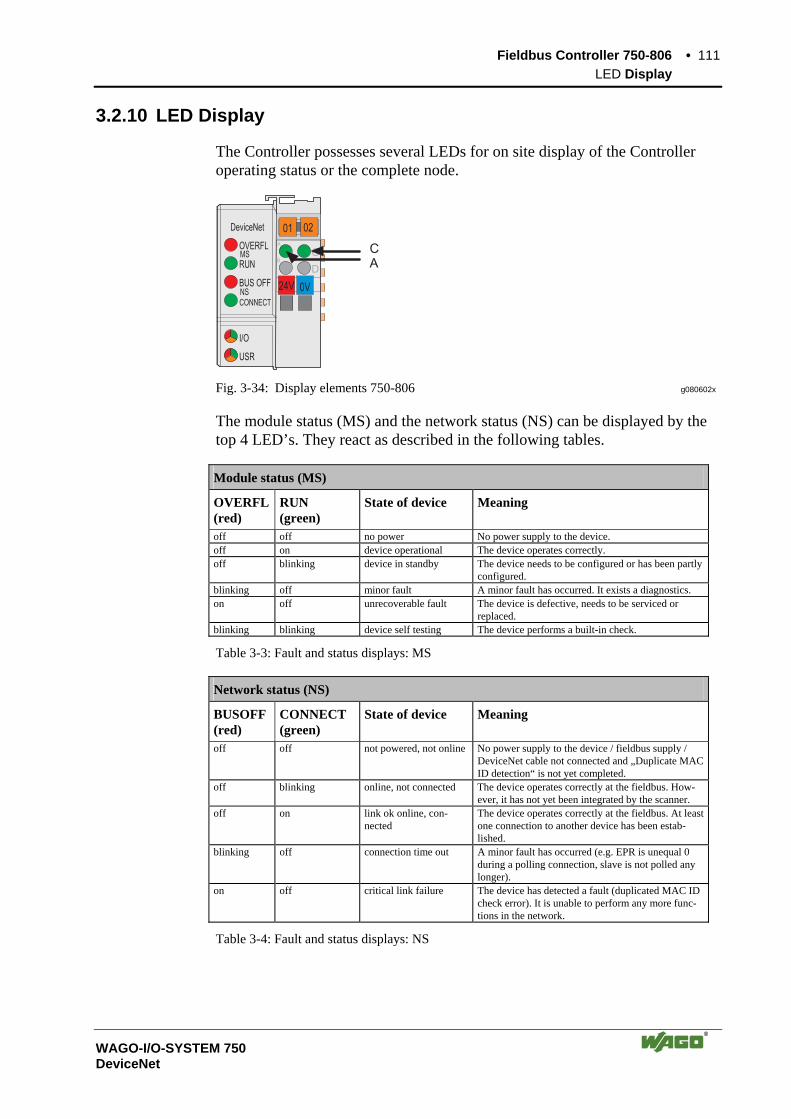
Fieldbus Controller 750-806 • 111 LED Display
WAGO-I/O-SYSTEM 750 DeviceNet
3.2.10 LED Display
The Controller possesses several LEDs for on site display of the Controller operating status or the complete node.
24V 0V
01 02
I/O
DeviceNet
C
DB
A
USR
OVERFL
RUN
BUS OFF
CONNECTNS
MSCA
Fig. 3-34: Display elements 750-806 g080602x
The module status (MS) and the network status (NS) can be displayed by the top 4 LED’s. They react as described in the following tables.
Module status (MS)
OVERFL(red)
RUN (green)
State of device Meaning
off off no power No power supply to the device. off on device operational The device operates correctly. off blinking device in standby The device needs to be configured or has been partly
configured. blinking off minor fault A minor fault has occurred. It exists a diagnostics. on off unrecoverable fault The device is defective, needs to be serviced or
replaced. blinking blinking device self testing The device performs a built-in check.
Table 3-3: Fault and status displays: MS
Network status (NS)
BUSOFF (red)
CONNECT (green)
State of device Meaning
off off not powered, not online No power supply to the device / fieldbus supply / DeviceNet cable not connected and „Duplicate MAC ID detection“ is not yet completed.
off blinking online, not connected The device operates correctly at the fieldbus. How-ever, it has not yet been integrated by the scanner.
off on link ok online, con-nected
The device operates correctly at the fieldbus. At least one connection to another device has been estab-lished.
blinking off connection time out A minor fault has occurred (e.g. EPR is unequal 0 during a polling connection, slave is not polled any longer).
on off critical link failure The device has detected a fault (duplicated MAC ID check error). It is unable to perform any more func-tions in the network.
Table 3-4: Fault and status displays: NS

112 • Fieldbus Controller 750-806 LED Display
WAGO-I/O-SYSTEM 750 DeviceNet
3.2.10.1 Node status – Blink code from the 'I/O' LED
The ‘I/O‘-LED displays the communication status of the internal bus. Addi-tionally, this LED is used to display fault codes (blink codes) in the event of a system error.
LED Meaning Trouble shooting
I/O Green Fieldbus coupler operating perfectly, Data cycle on the
internal bus
Off No data cycle on the internal bus Red a) During startup of fieldbus controller:
Internal bus being initialized, Startup displayed by LED flashing fast for approx. 1-2 seconds
Red b) After startup of fieldbus controller: Errors, which occur, are indicated by three conse- cutive flashing sequences. There is a short pause between each sequential flash.
Evaluate the fault message (fault code and fault argument).
The controller starts up after switching on the supply voltage. The "I/O" LED blinks. The "I/O" LED has a steady light following a fault free start-up. In the case of a fault the "I/O" LED continues blinking. The fault is cyclically displayed by the blink code.
Detailed fault messages are displayed with the aid of a blink code. A fault is cyclically displayed with up to 3 blink sequences.
• The first blink sequence (approx. 10 Hz) starts the fault display.
• The second blink sequence (approx. 1 Hz) following a pause. The number of blink pulses indicates the fault code.
• The third blink sequence (approx. 1 Hz) follows after a further pause. The number of blink pulses indicates the fault argument.

Fieldbus Controller 750-806 • 113 LED Display
WAGO-I/O-SYSTEM 750 DeviceNet
“I/O”-LED is blinking
Test o.k.?No
Yes
“I/O”-LED is shining
ready for operation
2nd break
1st break
“I/O” LED1st flash sequence(Introduction of theerror indication)
“I/O” LED2nd flash sequenceError code(Number of flash cycles)
“I/O” LED3rd flash sequenceError argument(Number of flash cycles)
Coupler/Controller starts up
Switching onthe power supply
Fig. 3-35: Signalling the LED's node status g012111e
After clearing a fault, restart the coupler by cycling the power.
I/O Meaning
green Data cycle on the internal bus
off No data cycle on the internal bus
red Controller hardware defective
red blinks
When starting: internal bus is initialized During operation: general internal bus fault
red blinks cyclically
Fault message during internal bus reset and internal fault:
orange MAC-ID is changed via SW and is different to the DIP switch setting
Fault message of the ‘I/O‘-LED
1 st flash sequence: Start of the Fault message 2 nd flash sequence: Fault code 3 rd flash sequence: Fault argument

114 • Fieldbus Controller 750-806 LED Display
WAGO-I/O-SYSTEM 750 DeviceNet
Fault code 1: "Hardware and Configuration fault"
Fault argument Fault description Trouble shooting - Invalid checksum within the
parameter range of fieldbus cou-pler
Turn off the power supply of the node, exchange the bus coupler and turn the power supply on again.
1 Overflow of the internal buffer memory for the inline code
Turn off the power supply of the node, reduce number of I/O mod-ules and turn the power supply on again. If the error still exists, exchange the bus coupler.
2 I/O module(s) with unsupported data type
Detect faulty I/O module as fol-lows: turn off the power supply. Place the end module in the mid-dle of the fieldbus node. Turn the power supply on again. – If the LED is still blinking, turn off the power supply and place the end module in the middle of the first half of the node (towards the coupler). – If the LED doesn’t blink, turn off the power supply and place the end module in the middle of the second half of the node (away from the coupler). Turn the power supply on again. Repeat this procedure until the faulty I/O module is detected. Replace the faulty I/O module. Ask about a firmware update for the fieldbus coupler.
3 Unknown program module type of the flash program memory
Turn off the power supply of the node, exchange the bus coupler and turn the power supply on again.
4 Fault when writing data within the flash memory
Turn off the power supply of the node, exchange the bus coupler and turn the power supply on again.
5 Fault when deleting a flash sec-tor
Turn off the power supply of the node, exchange the bus coupler and turn the power supply on again.
6 Changed I/O module configura-tion determined after AUTORESET
Restart the fieldbus coupler by turning the power supply off and on again.
7 Fault when writing data in the serial EEPROM
Turn off the power supply of the node, exchange the bus coupler and turn the power supply on again.
8 Invalid Hardware Firmware combination
Turn off the power supply of the node, exchange the bus coupler and turn the power supply on again.
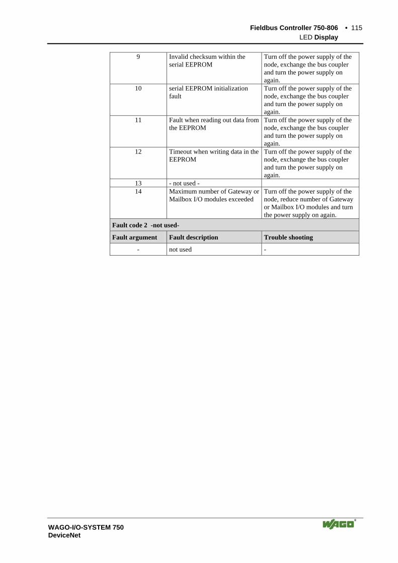
Fieldbus Controller 750-806 • 115 LED Display
WAGO-I/O-SYSTEM 750 DeviceNet
9 Invalid checksum within the serial EEPROM
Turn off the power supply of the node, exchange the bus coupler and turn the power supply on again.
10 serial EEPROM initialization fault
Turn off the power supply of the node, exchange the bus coupler and turn the power supply on again.
11 Fault when reading out data from the EEPROM
Turn off the power supply of the node, exchange the bus coupler and turn the power supply on again.
12 Timeout when writing data in the EEPROM
Turn off the power supply of the node, exchange the bus coupler and turn the power supply on again.
13 - not used - 14 Maximum number of Gateway or
Mailbox I/O modules exceeded Turn off the power supply of the node, reduce number of Gateway or Mailbox I/O modules and turn the power supply on again.
Fault code 2 -not used-
Fault argument Fault description Trouble shooting
- not used -
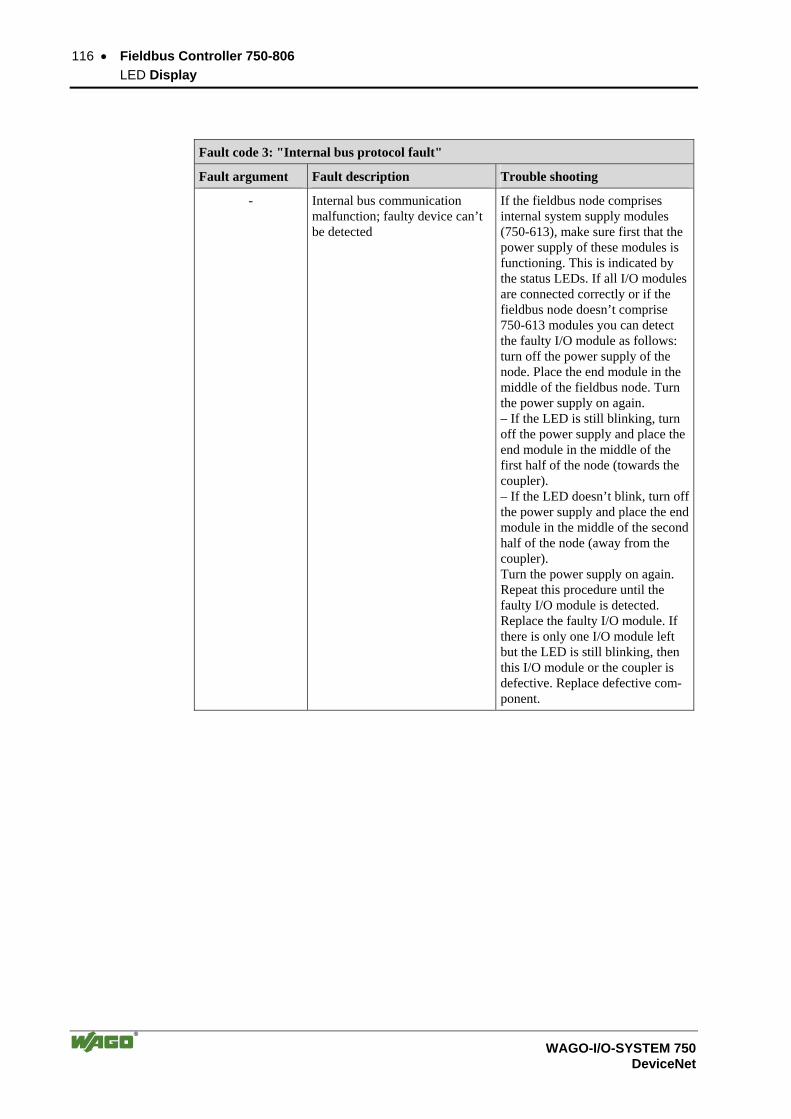
116 • Fieldbus Controller 750-806 LED Display
WAGO-I/O-SYSTEM 750 DeviceNet
Fault code 3: "Internal bus protocol fault"
Fault argument Fault description Trouble shooting
- Internal bus communication malfunction; faulty device can’t be detected
If the fieldbus node comprises internal system supply modules (750-613), make sure first that the power supply of these modules is functioning. This is indicated by the status LEDs. If all I/O modules are connected correctly or if the fieldbus node doesn’t comprise 750-613 modules you can detect the faulty I/O module as follows: turn off the power supply of the node. Place the end module in the middle of the fieldbus node. Turn the power supply on again. – If the LED is still blinking, turn off the power supply and place the end module in the middle of the first half of the node (towards the coupler). – If the LED doesn’t blink, turn off the power supply and place the end module in the middle of the second half of the node (away from the coupler). Turn the power supply on again. Repeat this procedure until the faulty I/O module is detected. Replace the faulty I/O module. If there is only one I/O module left but the LED is still blinking, then this I/O module or the coupler is defective. Replace defective com-ponent.
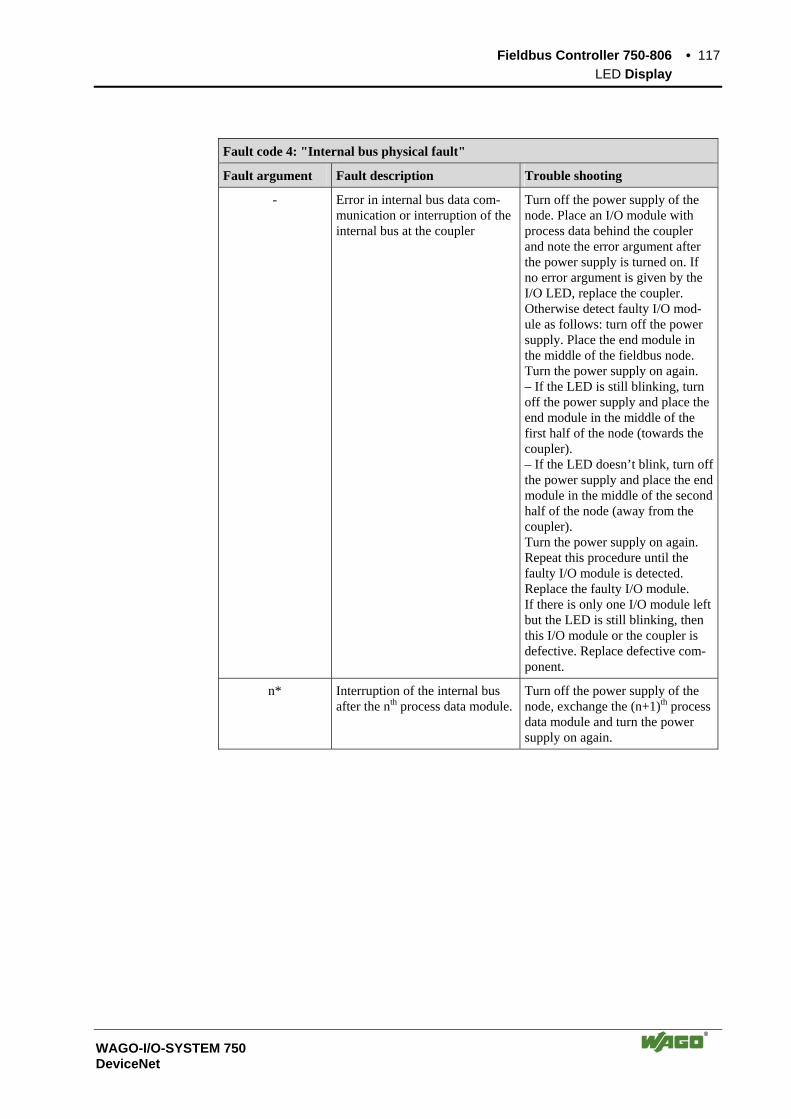
Fieldbus Controller 750-806 • 117 LED Display
WAGO-I/O-SYSTEM 750 DeviceNet
Fault code 4: "Internal bus physical fault"
Fault argument Fault description Trouble shooting
- Error in internal bus data com-munication or interruption of the internal bus at the coupler
Turn off the power supply of the node. Place an I/O module with process data behind the coupler and note the error argument after the power supply is turned on. If no error argument is given by the I/O LED, replace the coupler. Otherwise detect faulty I/O mod-ule as follows: turn off the power supply. Place the end module in the middle of the fieldbus node. Turn the power supply on again. – If the LED is still blinking, turn off the power supply and place the end module in the middle of the first half of the node (towards the coupler). – If the LED doesn’t blink, turn off the power supply and place the end module in the middle of the second half of the node (away from the coupler). Turn the power supply on again. Repeat this procedure until the faulty I/O module is detected. Replace the faulty I/O module. If there is only one I/O module left but the LED is still blinking, then this I/O module or the coupler is defective. Replace defective com-ponent.
n* Interruption of the internal bus after the nth process data module.
Turn off the power supply of the node, exchange the (n+1)th process data module and turn the power supply on again.

118 • Fieldbus Controller 750-806 LED Display
WAGO-I/O-SYSTEM 750 DeviceNet
Fault code 5: "Internal bus initialization fault"
Fault argument Fault description Trouble shooting
n* Error in register communication during internal bus initialization
Turn off the power supply of the node and replace nth process data module and turn the power supply on again.
Fault code 6 -not used-
Fault argument Fault description Trouble shooting
- not used -
Fault code 7 -not used-
Fault argument Fault description Trouble shooting
- not used -
Fault code 8 -not used-
Fault argument Fault description Trouble shooting
- not used -
Fault code 9 "CPU Trap Error"
Fault argument Fault description Trouble shooting
1 Illegal Opcode
2 Stack overflow
3 Stack underflow
4 NMI
Error in the program sequence. Contact the WAGO I/O-Support
Fault code 10: "PLC program fault " Fault argument Fault description Trouble shooting
1 Invalid Offset address for digital inputs
Correct the Offset address in the associated function block.
2 Invalid Offset address for digital outputs
Correct the Offset address in the associated function block.
Fault code 11: "Gateway-/Mailbox I/O module fault" Fault argument Fault description Trouble shooting
1 Maximum number of Gateway modules exceeded
Turn off the power supply of the node, reduce number of Gateway modules and turn the power supply on again.
2 Maximum size of Mailbox ex-ceeded
Reduce the Mailbox size.
3 Maximum size of process image exceeded due to the put Gateway modules
Reduce the data width of the Gateway modules.
* The number of blink pulses (n) indicates the position of the I/O module. I/O modules without data are not counted (e.g. supply module without diagnosis)

Fieldbus Controller 750-806 • 119 LED Display
WAGO-I/O-SYSTEM 750 DeviceNet
Example for a fault message; Fault: The 13th I/O module has been removed
1. The "I/O" LED starts the fault display with the first blink sequence (approx. 10 flashes/second).
2. The second blink sequence (1 flash/second) follows the first pause. The "I/O" LED blinks four times and thus signals the fault code 4 (internal bus data fault).
3. The third blink sequence follows the second pause. The "I/O " LED blinks twelve times. The fault argument 12 means that the internal bus is interrupted after the 12th I/O module.
3.2.10.2 Supply voltage status
The two green LED’s in the coupler supply section, display the status of the supply voltage. The left LED (A) indicates the status of the 24 V supply for the coupler. The right hand LED (‘B‘ or ‘C‘) displays the status of the field side supply (i.e., the power jumper contacts).
LED Meaning Trouble shooting
A
Green Operating voltage for the system exists.
OFF No operating voltage for the system. Check the supply voltage (24V and 0V).
B or C
Green Operating voltage for the power jumper contacts exists.
OFF No operating voltage for the the power jumper contacts.
Check the supply voltage (24V and 0V).

120 • Fieldbus Controller 750-806 Technical Data
WAGO-I/O-SYSTEM 750 DeviceNet
3.2.11 Technical Data
System data
Max. no. of nodes 64 with scanner
Max. no. of I/O points ca. 6000 (depends on master)
Transmission medium shielded Cu cable, trunk line: AWG 15, 18 (2x 0.82mm2 +2x1.7mm2)drop line: AWG 22, 24 (2x0.2mm2 +2x0.32mm2)
Max. length of bus line 100 m ... 500 m (baud rate dependent / cable dependent)
Baud rate 125 kBaud, 250 kBaud, 500 kBaud
Bus coupler connection 5-pole male connector, series 231 (MCS) female connector 231-305/010-000/050-000 is included
Programming WAGO-I/O-PRO 32
IEC 61131-3 IL, LD, FBD, ST, FC
Standards and approvals
UL E175199, UL 508 E198726, UL 1604 Clas I Div2 ABCD T4A (applied for)
DEMKO 02ATEX132273 X II 3 GD EEx nA II T4
Conformity marking CE
Accessories
EDS-Dateien Download: www.wago.com
Miniature WSB quick marking system
Technical data
Max. number of I/O modules 64
Fieldbus
Input process image max. 1024 Byte
Output process image max. 1024 Byte
Input variables max. 512 Byte
Output variables max. 512 Byte
Program memory 128 kByte
Data memory 64 kByte
Non-volatile memory 8 kByte (retain)
Cycle time < 3 ms for 1,000 statements /256 dig. I/Os
Configuration via PC or control
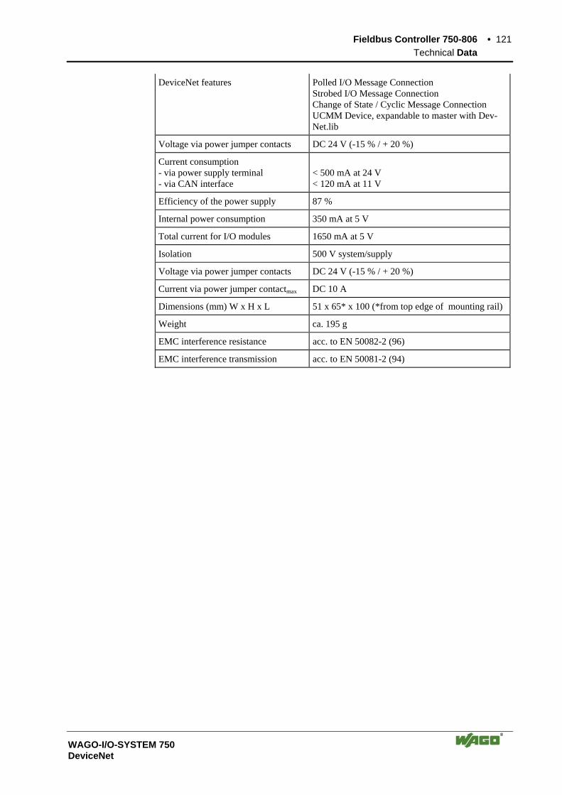
Fieldbus Controller 750-806 • 121 Technical Data
WAGO-I/O-SYSTEM 750 DeviceNet
DeviceNet features Polled I/O Message Connection Strobed I/O Message Connection Change of State / Cyclic Message Connection UCMM Device, expandable to master with Dev-Net.lib
Voltage via power jumper contacts DC 24 V (-15 % / + 20 %)
Current consumption - via power supply terminal - via CAN interface
< 500 mA at 24 V < 120 mA at 11 V
Efficiency of the power supply 87 %
Internal power consumption 350 mA at 5 V
Total current for I/O modules 1650 mA at 5 V
Isolation 500 V system/supply
Voltage via power jumper contacts DC 24 V (-15 % / + 20 %)
Current via power jumper contactmax DC 10 A
Dimensions (mm) W x H x L 51 x 65* x 100 (*from top edge of mounting rail)
Weight ca. 195 g
EMC interference resistance acc. to EN 50082-2 (96)
EMC interference transmission acc. to EN 50081-2 (94)

122 • Description Technical Data
WAGO-I/O-SYSTEM 750 DeviceNet
4 DeviceNet 4.1 Description
DeviceNet is a networking concept in the device level based on the serial bus system CAN (Controller Area Network). It is particularly distinguished by the problem-free addition and removal of devices, from simple light barriers up to complex motor controls during operation. DeviceNet is mainly used in indus-trial automation and for robot controls.
The Data Link Layer, i.e. the physical and data storage layer, is defined in the CAN specification. The telegram architecture is described. However, there is no information about the application layer. This is where DeviceNet comes into play. It describes the defined meaning of the data transmitted in the application layer.
The Open DeviceNet Vendor Association (abridged: ODVA) is the user or-ganisation for DeviceNet. In a specification, the ODVA DeviceNet is defined as a uniform application layer and it lays down technical and functional fea-tures for device networking. A maximum of 64 fieldbus nodes can be operated in one DeviceNet network. The extension of the network depends on the selected baud rate (125 kBaud, 250 kBaud or 500 kBaud).
In contrast to other fieldbus systems, CAN does not address the modules con-nected to the bus but identifies the messages. Whenever the bus is free, sub-scribers are allowed to send messages. Each bus subscriber decides on its own when it wants to send data or instigate other bus subscribers to send data. This permits a communication without a bus master assembly group. Bus conflicts are solved in that the messages are assigned a certain priority. This priority is defined by the CAN identifier, called Connection ID in De-viceNet. The following rule applies: the smaller the identifier, the higher the priority. A general distinction between high priority process messages (I/O Messages) and low priority management messages (Explicit Messages) is done before. Messages having a data length of more than 8 bytes can be fragmented.
The communication with DeviceNet occurs always connection-referenced (connection based). All data and functions of a device are described by means of an object model. Therefore, for a message exchange directly after switching on a device, the connections to the desired subscriber have to be established first and communication objects be created or allocated. Message distribution is according to the broadcast system, data exchange according to the producer consumer model.
A transmitting DeviceNet node produces data that is either consumed via a point-to-point connection (1 to 1) by one receiving node, or via a multicast connection (1 to n) by several receiving nodes.

Network Architecture • 123 Transmission Media
WAGO-I/O-SYSTEM 750 DeviceNet
Further information The Open DeviceNet Vendor Association (ODVA) provides further docu-ments in the Internet under: http://www.odva.org
4.2 Network Architecture
4.2.1 Transmission Media
4.2.1.1 Type of Cable
A bus medium forms the basis for the physical realization of a network using DeviceNet. According to the line specification, a double 2-conductor twisted pair cable (twisted pair, screened cable) is recommended to be used as a medium. It consists of two screened twisted pair cables with a wire in the middle of the cable. Further screening extended at the outside. The blue and the white twisted pair cable is used for signal transmission, the black and red one for the supply voltage.
4.2.1.2 Cable Types
The DeviceNet bus is configured using a remote bus cable as the trunk line and several drop lines.
For this purpose, the DeviceNet specification distinguishes between 2 cable types:
• Thick Cable For the trunk line of maximum 8 A or for networks extending over more than 100 m. The trunk line topology is linear, i.e. the remote bus cables are not further branched. On each end of the remote bus cable, terminating resistors are required.
• Thin Cable For drop lines with maximum 3 A or for networks extending less than 100 m. One or more nodes can be connected to the drop lines, in other words, branching is permitted here. The length of the individual drop lines is measured from the branching point of the node and can be up to 6 m. The entire length of the drop line depends on the Baud rate.
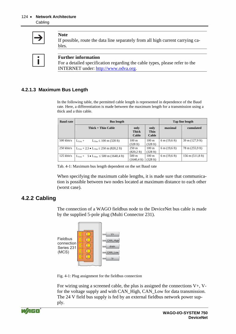
124 • Network Architecture Cabling
WAGO-I/O-SYSTEM 750 DeviceNet
Note If possible, route the data line separately from all high current carrying ca-bles.
Further information For a detailed specification regarding the cable types, please refer to the INTERNET under: http://www.odva.org.
4.2.1.3 Maximum Bus Length
In the following table, the permitted cable length is represented in dependence of the Baud rate. Here, a differentiation is made between the maximum length for a transmission using a thick and a thin cable.
Bus length Tap line length Baud rate
Thick + Thin Cable only Thick Cable
only Thin Cable
maximal cumulated
500 kbit/s LTick + LThin ≤ 100 m (328 ft) 100 m (328 ft)
100 m (328 ft)
6 m (19,6 ft) 39 m (127,9 ft)
250 kbit/s LTick + 2,5 • LThin ≤ 250 m (820,2 ft) 250 m (820,2 ft)
100 m (328 ft)
6 m (19,6 ft) 78 m (255,9 ft)
125 kbit/s LTick + 5 • LThin ≤ 500 m (1640,4 ft) 500 m (1640,4 ft)
100 m (328 ft)
6 m (19,6 ft) 156 m (511,8 ft)
Tab. 4-1: Maximum bus length dependent on the set Baud rate
When specifying the maximum cable lengths, it is made sure that communica-tion is possible between two nodes located at maximum distance to each other (worst case).
4.2.2 Cabling
The connection of a WAGO fieldbus node to the DeviceNet bus cable is made by the supplied 5-pole plug (Multi Connector 231).
FieldbusconnectionSeries 231(MCS)
CAN_High
drain
CAN_Low
V-
V+
Fig. 4-1: Plug assignment for the fieldbus connection
For wiring using a screened cable, the plus is assigned the connections V+, V- for the voltage supply and with CAN_High, CAN_Low for data transmission. The 24 V field bus supply is fed by an external fieldbus network power sup-ply.
Network Architecture • 125 Cabling
WAGO-I/O-SYSTEM 750 DeviceNet
CAN_High and CAN_Low are two physically different bus levels. The cable screen is connected to the drain connection. This is terminated with a 1 MΩ resistor to the DIN rail via the clip on the bot-tom of the Coupler/Controller. The DIN rail must then be directly connected to the Grounding Stud that must be connected to Earth Ground. We strongly recommend a central Earth Ground for the entire DeviceNet Bus conductor screening. A low Ohm connection of the screening on PE terminal can only be made externally.
Note WAGO offers the screen connection system (series 790) for an optimum con-nection between fieldbus cable screening and functional earth.
Each DeviceNet node forms the differential voltage UDiff with: UDiff = UCAN_High - UCAN_Low. using the bus levels CAN_High and CAN_Low. Differential signal transmission offers the advantage of an insensitivity com-pared to common mode malfunctions and ground offset between the nodes.
Note
At its conductor ends, the bus cable must always be connected with a match-ing resistor of 120 Ohm to avoid reflections and, as a result, transmission problems. This is also required for very short conductor lengths.
The CAN bus is a 2-wire bus and bus error management can detect a cable break or a short-circuit by the asymmetric operation.
Further information The CiA provides documents regarding specifications, especially cable specifi-cations on the Internet under:
http://www.can-cia.de
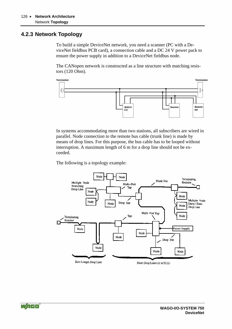
126 • Network Architecture Network Topology
WAGO-I/O-SYSTEM 750 DeviceNet
4.2.3 Network Topology
To build a simple DeviceNet network, you need a scanner (PC with a De-viceNet fieldbus PCB card), a connection cable and a DC 24 V power pack to ensure the power supply in addition to a DeviceNet fieldbus node.
The CANopen network is constructed as a line structure with matching resis-tors (120 Ohm).
WAGO I/O
Scanner Busnetz-teil
Termination
120
Termination
120
In systems accommodating more than two stations, all subscribers are wired in parallel. Node connection to the remote bus cable (trunk line) is made by means of drop lines. For this purpose, the bus cable has to be looped without interruption. A maximum length of 6 m for a drop line should not be ex-ceeded.
The following is a topology example:
Power Supply

Network Architecture • 127 Network Grounding
WAGO-I/O-SYSTEM 750 DeviceNet
WAGO Kontakttechnik GmbH has developed a Multi-Port DeviceNet Tap to connect the nodes to permit the connection of remote bus cables and drop lines using the CAGE CLAMP® technology. This achieves a reliable, fast and vi-bration and corrosion resistant connection. The DeviceNet taps are available in 2 designs.
Article Description
810-900/000-001 Enclosed design with connection possibilities for 6 lines. The housing provides a protection in difficult environ-mental conditions.
810-901/000-001 Open design to which 2 drop lines and 2 remote bus lines (trunk lines) can be connected.
All subscribers in the network communicate at the same Baud rate. The bus structure permits the interference-free connection and disconnection of sta-tions or a stepped start-up of the system. Future extensions have no influence on the stations already in operation. Should a subscriber fail or be added to the network as a new one, it is auto-matically deteced by the system.
4.2.4 Network Grounding
The devices can either be power supplied via the DevicNet bus or have their own power supply.
Prerequisite being, however, that the network is only grounded at one point. Preferably, grounding is in the network center (V and screen drain with round media) to optimize the capacity and minimize interference.
Not permitted are ground loops via devices that are not disconnected from the power supply. The device must either be insulated or, if this is not possible, the power must be correspondingly disconnected in the device.
4.2.5 Interface Modules
In a network, all WAGO DeviceNet fieldbus nodes are delivered to operate as slaves. The master operation is taken over by a central control system, such as PLC, NC or RC.
Note The programmable fieldbus Controller 750-806 can assume the master op-eration when being extended by the "DevNet.lib" library.
The connection to fieldbus devices is made via interface modules. As an interface module, WAGO offers the PC interface PCBs for DeviceNet, ISA DeviceNet Master 7KByte (order No. 758-340), PC104 DeviceNet Mas-ter 7KByte D-Sub,straight, angled (order No. 758-341) and PCI DeviceNet Master 7 Kbyte (order No. 758-342) from the WAGO-I/O-SYSTEM 758 Se-ries.
128 • Network Communication Objects, Classes, Instances and Attributes
WAGO-I/O-SYSTEM 750 DeviceNet
Other interface modules for programmable logic controls (PLCs) are also of-fered by other manufacturers.
4.3 Network Communication
4.3.1 Objects, Classes, Instances and Attributes
Protocol processing of DeviceNet is object oriented. Each node in the network is represented as a collection of objects. In the following, several terms con-nected with them are defined:
• Object: Object is an abstract representation of individual components within a de-vice belonging to each other. It is defined by its data or attributes, its ex-ternal functions or services available, and by its defined behaviour.
• Class: A class includes objects of a product belonging together, it is organized in instances, e.g. Identity Class, DeviceNet Class.
• Instance: An instance is composed of various variables (attributes). Differing in-stances of a class have the same services, the same behaviour and the same variables (attributes). However, they can have different variable values, e.g. different connection instances: Expilict Message, Poll I/O or Bit-Strobe connection instance.
• Attributes: The attributes represent data provided by a device via DeviceNet. They contain the current values, e.g. a configuration of an input, such as, for in-stance Vendor ID, Device Type or Product Name.
• Service: Services can be applied to classes and attributes. They perform defined ac-tions, e.g. reading of variables (attributes) or resetting a class.
• Behaviour: The behaviour defines how a device reacts as a consequence of external events, such as changed process data, or as a consequence of internal events, such as expiring timers.
Module Characteristics • 129 Communication Model
WAGO-I/O-SYSTEM 750 DeviceNet
4.4 Module Characteristics The I/O module is defined by vendor ID and device type.
Vendor ID 0x28 (40)
Device Type 0x0C (12), Communication Adapter
4.4.1 Communication Model
4.4.1.1 Message Groups
CAN messages are divided into several groups in order to achieve different priorities.
• message group 1 serves to exchange I/O data via I/O messages
• message group 2 is reserved for Master/Slave applications
• message group 3 serves to exchange configurations data via explicit mes-sages
• message group 4 is reserved for system administration (i. e. Offline Con-nection Set)
The CAN Identifier (Connection ID) and with it the priority is built via differ-ent message groups and the MAC ID.
4.4.1.2 Message Types
DeviceNet has 2 types of messages:
• I/O Messages and • Explicite Messages
4.4.1.2.1 I/O Messaging
I/O messages are sent by a node and can be received by one or several other nodes. Only I/O data is transmitted and no protocol data is specified by this way.
4.4.1.2.2 Explicit Messaging
Explicit messages are sent directly from one node to another. They consist of a request and an answer. Therefore services can be requested directly from an-other node. The data field consists of the service identification and the destina-tion address. The format of the explicit messages is defined. Via explicit mes-sages devices can be configured or a dynamic built-up of message connections can be made.
130 • Process data and Diagnostic Status I/O Messaging Connections
WAGO-I/O-SYSTEM 750 DeviceNet
4.4.2 I/O Messaging Connections
The transfer or exchange of process data between the scanner and the I/O de-vice is made via a „Polled I/O Connection“, „Change of State/Cyclic“ or „Bit Strobe“.
Polled I/O Connection Slaves are cyclically polled by the master.
Strobe Function All slaves are polled by the master by means of a command.
Change of State Messages are transmitted either cyclically by the master or the slave, or in the event of a state change.
4.5 Process data and Diagnostic Status The data is transmitted between master and slave in the form of objects, a dif-ferentiation being made between input and output objects. The object architec-ture is defined by assembly objects which serve to group attributes of differing application objects. I/O data of different objects can, for this reason, be grouped to form a data block and transmitted by a message connection.
4.5.1 Process Image
The process image is differentiated according to input and output process im-ages. The assembly object makes a statically configured process image avail-able in the instances 1 ... 9.
The desired process image can be selected by setting the Produced Connection Path and the Consumed Connection Path of the individual I/O connections (Poll, Bit Strobe, Change of State or Change of Value).
The architecture of the individual instances of the assembly object is described in the following.
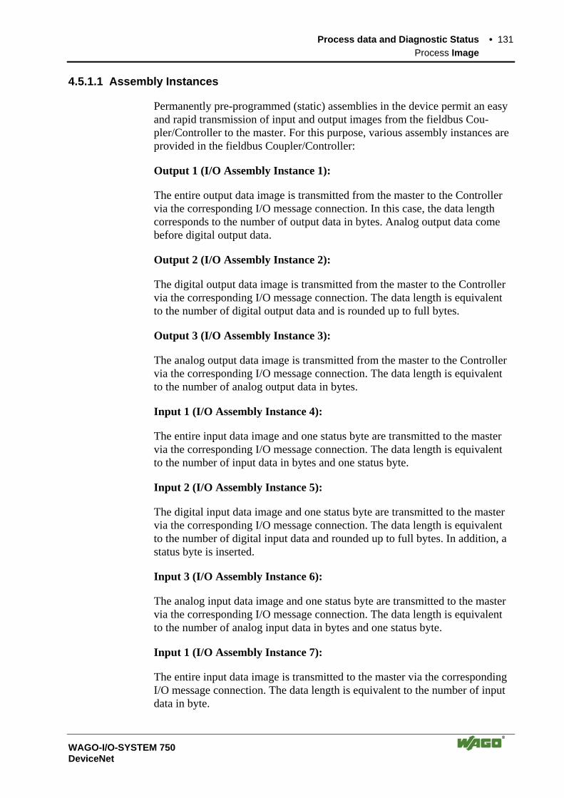
Process data and Diagnostic Status • 131 Process Image
WAGO-I/O-SYSTEM 750 DeviceNet
4.5.1.1 Assembly Instances
Permanently pre-programmed (static) assemblies in the device permit an easy and rapid transmission of input and output images from the fieldbus Cou-pler/Controller to the master. For this purpose, various assembly instances are provided in the fieldbus Coupler/Controller:
Output 1 (I/O Assembly Instance 1):
The entire output data image is transmitted from the master to the Controller via the corresponding I/O message connection. In this case, the data length corresponds to the number of output data in bytes. Analog output data come before digital output data.
Output 2 (I/O Assembly Instance 2):
The digital output data image is transmitted from the master to the Controller via the corresponding I/O message connection. The data length is equivalent to the number of digital output data and is rounded up to full bytes.
Output 3 (I/O Assembly Instance 3):
The analog output data image is transmitted from the master to the Controller via the corresponding I/O message connection. The data length is equivalent to the number of analog output data in bytes.
Input 1 (I/O Assembly Instance 4):
The entire input data image and one status byte are transmitted to the master via the corresponding I/O message connection. The data length is equivalent to the number of input data in bytes and one status byte.
Input 2 (I/O Assembly Instance 5):
The digital input data image and one status byte are transmitted to the master via the corresponding I/O message connection. The data length is equivalent to the number of digital input data and rounded up to full bytes. In addition, a status byte is inserted.
Input 3 (I/O Assembly Instance 6):
The analog input data image and one status byte are transmitted to the master via the corresponding I/O message connection. The data length is equivalent to the number of analog input data in bytes and one status byte.
Input 1 (I/O Assembly Instance 7):
The entire input data image is transmitted to the master via the corresponding I/O message connection. The data length is equivalent to the number of input data in byte.

132 • Process data and Diagnostic Status Process Image
WAGO-I/O-SYSTEM 750 DeviceNet
Input 2 (I/O Assembly Instance 8):
The digital input data image is transmitted to the master via the corresponding I/O message connection. The data length is equivalent to the number of digital input data and is rounded up to full bytes.
Input 3 (I/O Assembly Instance 9):
The analog input data image is transmitted to the master via the corresponding I/O message connection. The data length is equivalent to the number of analog input data in bytes.
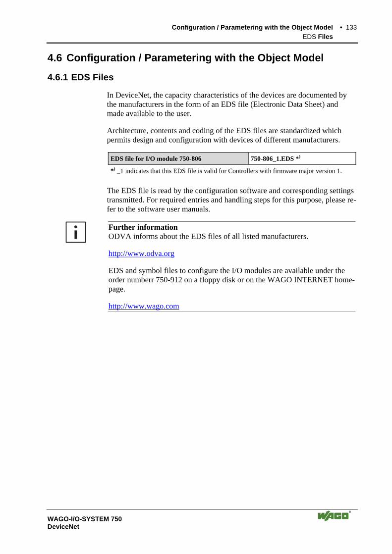
Configuration / Parametering with the Object Model • 133 EDS Files
WAGO-I/O-SYSTEM 750 DeviceNet
4.6 Configuration / Parametering with the Object Model
4.6.1 EDS Files
In DeviceNet, the capacity characteristics of the devices are documented by the manufacturers in the form of an EDS file (Electronic Data Sheet) and made available to the user.
Architecture, contents and coding of the EDS files are standardized which permits design and configuration with devices of different manufacturers.
EDS file for I/O module 750-806 750-806_1.EDS *)
*) _1 indicates that this EDS file is valid for Controllers with firmware major version 1.
The EDS file is read by the configuration software and corresponding settings transmitted. For required entries and handling steps for this purpose, please re-fer to the software user manuals.
Further information ODVA informs about the EDS files of all listed manufacturers.
http://www.odva.org
EDS and symbol files to configure the I/O modules are available under the order numberr 750-912 on a floppy disk or on the WAGO INTERNET home-page.
http://www.wago.com

134 • Configuration / Parametering with the Object Model Object Model
WAGO-I/O-SYSTEM 750 DeviceNet
4.6.2 Object Model
For network communication, DeviceNet uses an object model describing all device functions and data.
System Support Objects (general Management Objects)
• Identity Object
• Message Router Object
Communication Objects (Communications Objects for Data Exchange)
• DeviceNet Object
• Connection Object
Application Objects (Application Objects, to determine device function and/or configuration)
• Application Object(s)
• Assembly Object
• Parameter Object
Tabelle 4-1: Object model
Communication can be made exclusively connection oriented. For access by the network to the individual objects, first of all make connections between the desired subscribers and provide, or allocate, connection objects.
Data Type
USINT Unsigned Short INTeger (8 Bit)
UINT Unsigned INTeger (16 Bit)
USINT Unsigned Short INTeger (8 Bit)
UDINT Unsigned Double INTeger (32 Bit)
BOOL Boolean, True (1) or False (0)
STRUCT Structure of ...
ARRAY Array of ...
Note In the following, the object model for the fieldbus Coupler 750-306 and the fieldbus Controller 750-806 are listed. The explicit supplements to the fieldbus Controller 750-806 can be taken from the following chapter.

Configuration / Parametering with the Object Model • 135 Object Model
WAGO-I/O-SYSTEM 750 DeviceNet
4.6.2.1 Object Model for Coupler 750-306 and Controller 750-806
4.6.2.1.1 Classes of Coupler and Controller:
Object Class Instance Description Identity 0x01 1 Device type, vendor ID, serial number etc. Message Router 0x02 1 Routes explicit messages to the proper destination. DeviceNet 0x03 1 Maintains the physical connection to DeviceNet. This object
also allocates/deallocates the Master/Slave connection set. Assembly 0x04 9 Allows Data transmission of different objects over a single
connection, by binding attributes of multiple objects. Connection class 0x05 3 Allows explicit messages to be conducted. Acknowledge handler 0x2B 1 The Acknowledge Handler Object is used to manage the
reception of messages acknowledgements. This object com-municates with a message producing application object within a device. The Acknowledge Handler Object notifies the producing application of acknowledge reception, ac-knowledge timeouts amd production retry limit.
Coupler configuration object
0x64 1 Coupler and module configuration
Discrete input point 0x65 0...255 Digital input channel objects Discrete output point 0x66 0...255 Digital output channel objects Analog input point 0x67 0...255 Analog input channel objects Analog output point 0x68 0...255 Analog output channel objects
4.6.2.1.2 Identity Class (0x01):
Instance 0: Attribute ID
Used in buscoupler
Access rule
Name Data type Description Value
1 required get Revision UINT Revision of the Identity Object, Range 1-65535, class definition upon which the implementation is based.
0x01
Instance 1: Attribute ID
Used in buscoupler
Access rule
Name Data type Description Default Value
1 required get Vendor UINT Identification of vendor 40 (0x28) 2 required get Device
Type UINT Indication of general type of
product 12 (0x0C)
3 required get Product Code
UINT Identification of particular product of an individual vendor
i. e. 306 (0x132) for the 750-306
4 required get Revision Major/ Minor
Stuct: USINT, USINT
Revision of the item the Identity object represents
i. e. 3;0for the 750-306
5 required get Status WORD status of device - 6 required get Serial_
number UDINT Serial number of device -
7 required get Product name
SHORT_ STRING (num,char char...)
Human readable identification i. e. „WAGO 750-306 V 3.0)“ for the 750-306
Services: Service Code Service Name Description 0x0E Get_Attribute_Single Returns the contents of the specified attribute 0x05 Reset Invokes the reset service for the device
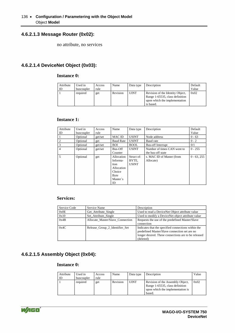
136 • Configuration / Parametering with the Object Model Object Model
WAGO-I/O-SYSTEM 750 DeviceNet
4.6.2.1.3 Message Router (0x02):
no attribute, no services
4.6.2.1.4 DeviceNet Object (0x03):
Instance 0:
Attribute ID
Used in buscoupler
Access rule
Name Data type Description Default Value
1 required get Revision UINT Revision of the Identity Object, Range 1-65535, class definition upon which the implementation is based.
0x02
Instance 1:
Attribute ID
Used in buscoupler
Access rule
Name Data type Description Default Value
1 Optional get/set MAC ID USINT Node address 0 - 63 2 Optional get Baud Rate USINT Baud rate 0 - 2 3 Optional get/set BOI BOOL Bus-off Interrupt 0/1 4 Optional get/set Bus-Off
Counter USINT Number of times CAN went to
the bus-off state 0 - 255
5 Optional get Allocation Informa-tion Allocation Choice Byte Master`s ID
Struct of: BYTE, USINT
s. MAC ID of Master (from Allocate)
0 - 63, 255
Services:
Service Code Service Name Description 0x0E Get_Attribute_Single Used to read a DeviceNet Object attribute value 0x10 Set_Attribute_Single Used to modify a DeviceNet object attribute value 0x4B Allocate_Master/Slave_Connection Requests the use of the predefined Master/Slave
connection 0x4C Release_Group_2_Identifier_Set Indicates that the specified connections within the
predefined Master/Slave connection set are no longer desired. These connections are to be released (deleted)
4.6.2.1.5 Assembly Object (0x04):
Instance 0:
Attribute ID
Used in buscoupler
Access rule
Name Data type Description Value
1 required get Revision UINT Revision of the Assembly Object, Range 1-65535, class definition upon which the implementation is based.
0x02

Configuration / Parametering with the Object Model • 137 Object Model
WAGO-I/O-SYSTEM 750 DeviceNet
Description of the instances:
Instance ID
Description
1 References to the process image containing analog and digital output data. 2 References to the process image containing only digital output data. 3 References to the process image containing only analog output data. 4 References to the process image containing containing analog and digital input data plus status. 5 References to the process image containing only digital input data plus status. 6 References to the process image containing only analog input data plus status. 7 References to the process image containing analog and digital input data. 8 References to the process image containing only analog input data. 9 References to the process image containing only analog input data. 12 References to the process image: analog and digital input data plus Error Code 13 References to the process image: analog and digital input data plus Error Code and Error Argument 14 References to the process image: analog and digital input data plus Error Code and Error Argument,
Status
Instance 1:
Attribute ID
Used in buscoupler
Access rule
Name Data type Description Value
3 dep. on kind of connected modules
get/set Process image
Array of Byte
process image, collection of all modules process output data.
Instance 2:
Attribute ID
Used in buscoupler
Access rule
Name Data type Description Value
3 dep. on kind of connected modules
get/set Process image
Array of Byte
process image, collection of all modules process output data.
Instance 3:
Attribute ID
Used in buscoupler
Access rule
Name Data type Description Value
3 dep. on kind of connected modules
get/set Process image
Array of Byte
process image, collection of all analog modules process output data.
Instance 4:
Attribute ID
Used in buscoupler
Access rule
Name Data type Description Value
3 dep. on kind of connected modules
get Process image
Array of Byte
process image, collection of all modules process input data plus status byte.
Instance 5:
Attribute ID
Used in buscoupler
Access rule
Name Data type Description Value
3 dep. on kind of connected modules
get Process image
Array of Byte
process image, collection of all digital modules process input data plus status byte.
Instance 6:
Attribute ID
Used in buscoupler
Access rule
Name Data type Description Value
3 dep. on kind of connected modules
get Process image
Array of Byte
process image, collection of all analog modules process input data plus status byte.
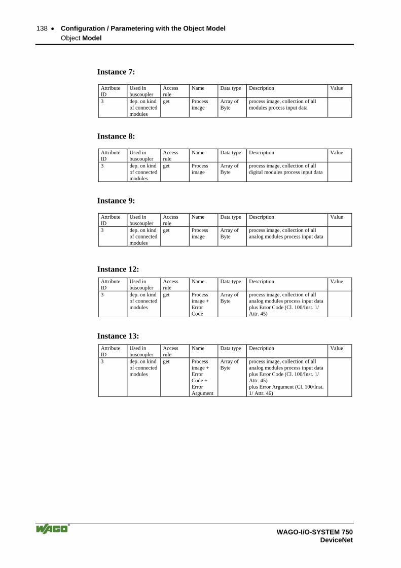
138 • Configuration / Parametering with the Object Model Object Model
WAGO-I/O-SYSTEM 750 DeviceNet
Instance 7:
Attribute ID
Used in buscoupler
Access rule
Name Data type Description Value
3 dep. on kind of connected modules
get Process image
Array of Byte
process image, collection of all modules process input data
Instance 8:
Attribute ID
Used in buscoupler
Access rule
Name Data type Description Value
3 dep. on kind of connected modules
get Process image
Array of Byte
process image, collection of all digital modules process input data
Instance 9:
Attribute ID
Used in buscoupler
Access rule
Name Data type Description Value
3 dep. on kind of connected modules
get Process image
Array of Byte
process image, collection of all analog modules process input data
Instance 12: Attribute ID
Used in buscoupler
Access rule
Name Data type Description Value
3 dep. on kind of connected modules
get Process image + Error Code
Array of Byte
process image, collection of all analog modules process input data plus Error Code (Cl. 100/Inst. 1/ Attr. 45)
Instance 13: Attribute ID
Used in buscoupler
Access rule
Name Data type Description Value
3 dep. on kind of connected modules
get Process image + Error Code + Error Argument
Array of Byte
process image, collection of all analog modules process input data plus Error Code (Cl. 100/Inst. 1/ Attr. 45) plus Error Argument (Cl. 100/Inst. 1/ Attr. 46)

Configuration / Parametering with the Object Model • 139 Object Model
WAGO-I/O-SYSTEM 750 DeviceNet
Instance 14: Attribute ID
Used in buscoupler
Access rule
Name Data type Description Value
3 dep. on kind of connected modules
get Process image + Error Code + Error Argument+ Status
Array of Byte
process image, collection of all analog modules process input dataplus Error Code (Cl. 100/Inst. 1/ Attr. 45) plus Error Argument (Cl. 100/Inst. 1/ Attr. 46) plus Status (Cl. 100/Inst. 1/Attr. 5)Plus Terminal diagnostic *) (Cl. 100/Inst. 1/Attr. 6) plus Diagnostic value*) (Cl. 100/ Inst. 1/Attr. 47), the diagnostic value is only valid, if in the Status is indicated, that a diagnostic message lies close *) Diagnostic is only possible for the Controller 750-806
Services:
Service Code Service Name Description 0x0E Get_Attribute_Single Used to read a DeviceNet Object attribute value 0x10 Set_Attribute_Single Used to modify a DeviceNet object attribute value
4.6.2.1.6 Connection Object (0x05):
Instance 0:
Attribute ID
Used in buscoupler
Access rule
Name Data type Description Default Value
1 required get Revision UINT Revision of the Connection Object, Range 1-65535, class definition upon which the im-plementation is based.
0x01
Description of the instances:
Instance ID Description 1 References the Explicit Messaging Connection into the Server 2 References the Poll I/O Connection 3 References Bit-Strobe I/O Connection 4 References the Slave´s Change of State or Cyclic I/O Connection 5 Reserved for „Reserved Identifier“, Message ID 1
Instance 1 (explicit messaging):
Attribute ID
Used in buscoupler
Access rule
Name Data type Description
1 available get state USINT State of the object 2 required get instance_
type USINT Indicates either I/O or Messaging Connection
3 required get transport-Class_ trigger
USINT defines behaviour of the connection
4 required get produced_connec-tion_id
UINT CAN Identifier field when the connection transmits
5 required get con-sumed_connec-
UINT CAN Identifier field value that denotes mes-sage to be received
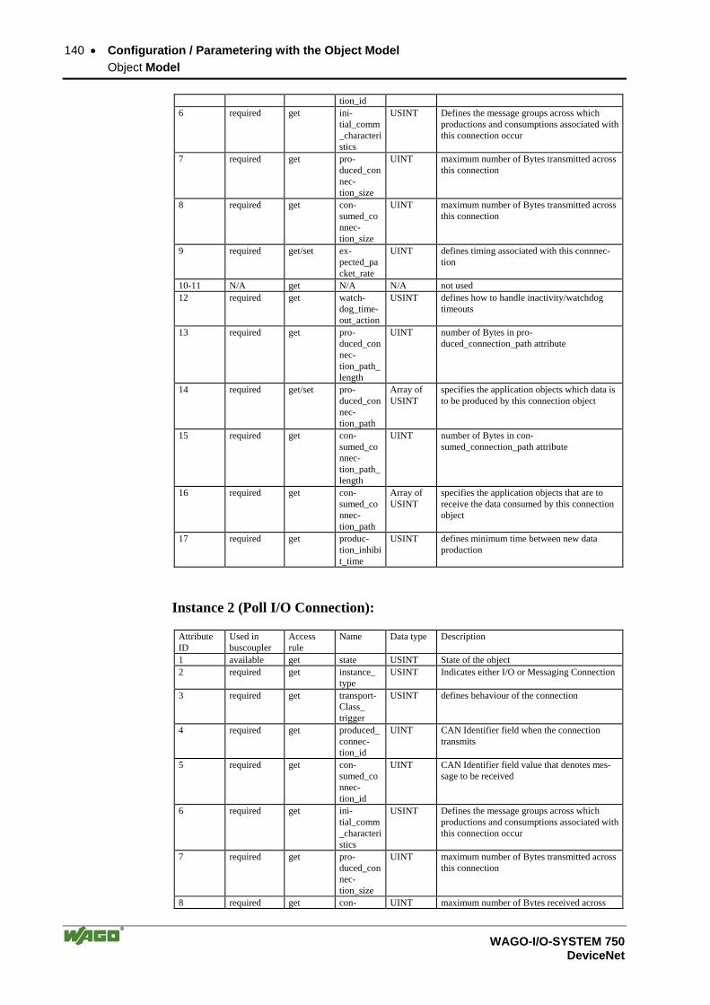
140 • Configuration / Parametering with the Object Model Object Model
WAGO-I/O-SYSTEM 750 DeviceNet
tion_id 6 required get ini-
tial_comm_characteristics
USINT Defines the message groups across which productions and consumptions associated with this connection occur
7 required get pro-duced_connec-tion_size
UINT maximum number of Bytes transmitted across this connection
8 required get con-sumed_connec-tion_size
UINT maximum number of Bytes transmitted across this connection
9 required get/set ex-pected_packet_rate
UINT defines timing associated with this connnec-tion
10-11 N/A get N/A N/A not used 12 required get watch-
dog_time-out_action
USINT defines how to handle inactivity/watchdog timeouts
13 required get pro-duced_connec-tion_path_length
UINT number of Bytes in pro-duced_connection_path attribute
14 required get/set pro-duced_connec-tion_path
Array of USINT
specifies the application objects which data is to be produced by this connection object
15 required get con-sumed_connec-tion_path_length
UINT number of Bytes in con-sumed_connection_path attribute
16 required get con-sumed_connec-tion_path
Array of USINT
specifies the application objects that are to receive the data consumed by this connection object
17 required get produc-tion_inhibit_time
USINT defines minimum time between new data production
Instance 2 (Poll I/O Connection):
Attribute ID
Used in buscoupler
Access rule
Name Data type Description
1 available get state USINT State of the object 2 required get instance_
type USINT Indicates either I/O or Messaging Connection
3 required get transport-Class_ trigger
USINT defines behaviour of the connection
4 required get produced_connec-tion_id
UINT CAN Identifier field when the connection transmits
5 required get con-sumed_connec-tion_id
UINT CAN Identifier field value that denotes mes-sage to be received
6 required get ini-tial_comm_characteristics
USINT Defines the message groups across which productions and consumptions associated with this connection occur
7 required get pro-duced_connec-tion_size
UINT maximum number of Bytes transmitted across this connection
8 required get con- UINT maximum number of Bytes received across

Configuration / Parametering with the Object Model • 141 Object Model
WAGO-I/O-SYSTEM 750 DeviceNet
sumed_connec-tion_size
this connection
9 required get/set ex-pected_packet_rate
UINT defines timing associated with this connnec-tion
10-11 N/A get N/A N/A not used 12 required get watch-
dog_time-out_action
USINT defines how to handle inactivity/watchdog timeouts
13 required get pro-duced_connec-tion_path_length
UINT number of Bytes in pro-duced_connection_path attribute
14 required get/set pro-duced_connec-tion_path
Array of USINT
specifies the application objects which data is to be produced by this connection object
15 required get con-sumed_connec-tion_path_length
UINT number of Bytes in con-sumed_connection_path attribute
16 required get/set con-sumed_connec-tion_path
Array of USINT
specifies the application objects that are to receive the data consumed by this connection object
17 required get produc-tion_inhibit_time
USINT defines minimum time between new data production
Instance 3 (Bit-Strobe I/O Connection):
Attribute ID
Used in buscoupler
Access rule
Name Data type Description
1 available get state USINT State of the object 2 required get instance_
type USINT Indicates either I/O or Messaging Connection
3 required get transport-Class_ trigger
USINT defines behaviour of the connection
4 required get produced_connec-tion_id
UINT CAN Identifier field when the connection transmits
5 required get con-sumed_connec-tion_id
UINT CAN Identifier field value that denotes mes-sage to be received
6 required get ini-tial_comm_characteristics
USINT Defines the message groups across which productions and consumptions associated with this connection occur
7 required get pro-duced_connec-tion_size
UINT maximum number of Bytes transmitted across this connection
8 required get con-sumed_connec-tion_size
UINT maximum number of Bytes received across this connection
9 required get/set ex-pected_packet_rate
UINT defines timing associated with this connnec-tion
10-11 N/A get N/A N/A not used 12 required get watch-
dog_time-out_action
USINT defines how to handle inactivity/watchdog timeouts

142 • Configuration / Parametering with the Object Model Object Model
WAGO-I/O-SYSTEM 750 DeviceNet
13 required get pro-duced_connec-tion_path_length
UINT number of Bytes in pro-duced_connection_path attribute
14 required get pro-duced_connec-tion_path
Array of USINT
specifies the application objects which data is to be produced by this connection object
15 required get con-sumed_connec-tion_path_length
UINT number of Bytes in con-sumed_connection_path attribute
16 required get con-sumed_connec-tion_path
Array of USINT
specifies the application objects that are to receive the data consumed by this connection object
17 required get produc-tion_inhibit_time
USINT defines minimum time between new data production
Instance 4 (Change of State and Cyclic I/O Connection):
Attribute ID
Used in buscoupler
Access rule
Name Data type Description
1 available get state USINT State of the object 2 required get instance_
type USINT Indicates either I/O or Messaging Connection
3 required get transport-Class_ trigger
USINT defines behaviour of the connection
4 required get produced_connec-tion_id
UINT CAN Identifier field when the connection transmits
5 required get con-sumed_connec-tion_id
UINT CAN Identifier field value that denotes mes-sage to be received
6 required get ini-tial_comm_characteristics
USINT Defines the message groups across which productions and consumptions associated with this connection occur
7 required get pro-duced_connec-tion_size
UINT maximum number of Bytes transmitted across this connection
8 required get con-sumed_connec-tion_size
UINT maximum number of Bytes received across this connection
9 required get/set ex-pected_packet_rate
UINT defines timing associated with this connnec-tion
10-11 N/A get N/A N/A not used 12 required get watch-
dog_time-out_action
USINT defines how to handle inactivity/watchdog timeouts
13 required get pro-duced_connec-tion_path_length
UINT number of Bytes in pro-duced_connection_path attribute
14 required get/set pro-duced_connec-tion_path
Array of USINT
specifies the application objects which data is to be produced by this connection object
15 required get con- UINT number of Bytes in con-
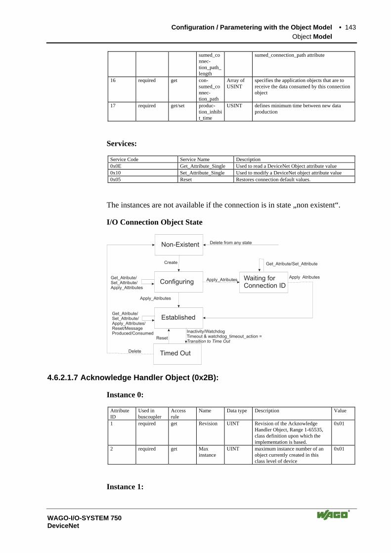
Configuration / Parametering with the Object Model • 143 Object Model
WAGO-I/O-SYSTEM 750 DeviceNet
sumed_connec-tion_path_length
sumed_connection_path attribute
16 required get con-sumed_connec-tion_path
Array of USINT
specifies the application objects that are to receive the data consumed by this connection object
17 required get/set produc-tion_inhibit_time
USINT defines minimum time between new data production
Services:
Service Code Service Name Description 0x0E Get_Attribute_Single Used to read a DeviceNet Object attribute value 0x10 Set_Attribute_Single Used to modify a DeviceNet object attribute value 0x05 Reset Restores connection default values.
The instances are not available if the connection is in state „non existent“.
I/O Connection Object State
Non-Existent Delete from any state
Get_Atribute/Set_Attribute
Get_Atribute/Set_Attribute/Apply_Attributes
Get_Atribute/Set_Attribute/Apply_Attributes/Reset/MessageProduced/Consumed
Apply Atributes
Apply_Atributes
Apply_Atributes
Create
Delete
Reset
Inactivity/WatchdogTimeout & watchdog_timeout_action =Transition to Time Out
Configuring
Established
Timed Out
Waiting forConnection ID
4.6.2.1.7 Acknowledge Handler Object (0x2B):
Instance 0:
Attribute ID
Used in buscoupler
Access rule
Name Data type Description Value
1 required get Revision UINT Revision of the Acknowledge Handler Object, Range 1-65535, class definition upon which the implementation is based.
0x01
2 required get Max instance
UINT maximum instance number of an object currently created in this class level of device
0x01
Instance 1:

144 • Configuration / Parametering with the Object Model Object Model
WAGO-I/O-SYSTEM 750 DeviceNet
Attribute ID
Used in buscoupler
Access rule
Name Data type Description Value
1 required get/set Acknowl-edge timer
UINT time to wait for acknowledge before resend-ing range 1-65,535 ms (0 invalid), default 16 ms
2 required get/set Retry limit USINT number of ack timeouts to wait before inform-ing the producing application of a Re-tryLimit_Reached event default=1, range 0-255; default 16 ms
3 required get COS Producing Connec-tion Instance
UINT 0x04, connection instance which contains the path of the producing I/O application object which will be notified of ack handler objects
Services:
Service Code Service Name Description 0x0E Get_Attribute_Single Used to read a DeviceNet Object attribute
value 0x10 Set_Attribute_Single Used to modify a DeviceNet object attribute
value
4.6.2.1.8 Coupler configuration object (0x64):
Instance 0:
Attribute ID
Used in buscoupler
Access rule
Name Data type Description Value
1 required get Revision UINT Revision of the Identity Object, Range 1-65535, class definition upon which the implementation is based.
0x01
2 required get Max instance
UINT maximum instance number of an object currently created in this class level of device
0x01
Instance 1:
Attribute ID
Used in buscoupler
Access rule
Name Data type
Description
1 specific get/set Bk_ModuleNo
USINT module number: 0-Coupler, 1- first module, 2-2.module
2 specific get/set Bk_TableNo USINT table number: 0 ... 256; not all existing 3 specific get/set Bk_Register
No USINT Register number: 0...255 for the Coupler
(0...63 for modules) 4 specific get/set Bk_Data UINT Register data , Status 5 specific get ProcessState USINT Coupler status: 0x01 module communication
error, 0x02 internal bus error , 0x08: module diagnostic , 0x80 fieldbus error
6 specific get DNS_i_Trmnldia (**)
UINT Module diagnostic, 0x8000 to decode a message, High Byte (Bit14...8): channel number, Low Byte (Bit7..0) Module number
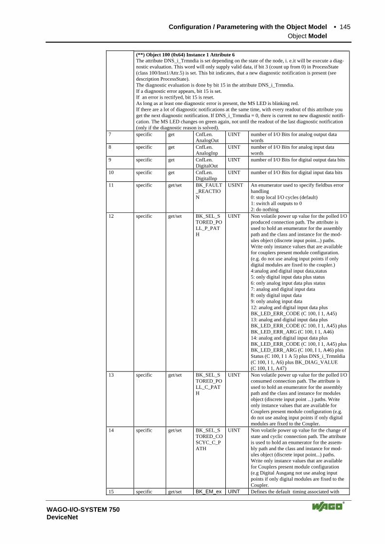
Configuration / Parametering with the Object Model • 145 Object Model
WAGO-I/O-SYSTEM 750 DeviceNet
(**) Object 100 (0x64) Instance 1 Attribute 6 The attribute DNS_i_Trmndia is set depending on the state of the node, i. e.it will be execute a diag-nostic evaluation. This word will only supply valid data, if bit 3 (count up from 0) in ProcessState (class 100/Inst1/Attr.5) is set. This bit indicates, that a new diagnostic notification is present (see description ProcessState). The diagnostic evaluation is done by bit 15 in the attribute DNS_i_Trmndia. If a diagnostic error appears, bit 15 is set. If an error is rectifyed, bit 15 is reset. As long as at least one diagnostic error is present, the MS LED is blinking red. If there are a lot of diagnostic notifications at the same time, with every readout of this attribute you get the next diagnostic notification. If DNS_i_Trmndia = 0, there is current no new diagnostic notifi-cation. The MS LED changes on green again, not until the readout of the last diagnostic notification (only if the diagnostic reason is solved).
7 specific get CnfLen. AnalogOut
UINT number of I/O Bits for analog output data words
8 specific get CnfLen. AnalogInp
UINT number of I/O Bits for analog input data words
9 specific get CnfLen. DigitalOut
UINT number of I/O Bits for digital output data bits
10 specific get CnfLen. DigitalInp
UINT number of I/O Bits for digital input data bits
11 specific get/set BK_FAULT_REACTION
USINT An enumerator used to specify fieldbus error handling 0: stop local I/O cycles (default) 1: switch all outputs to 0 2: do nothing
12 specific get/set BK_SEL_STORED_POLL_P_PATH
UINT Non volatile power up value for the polled I/O produced connection path. The attribute is used to hold an enumerator for the assembly path and the class and instance for the mod-ules object (discrete input point...) paths. Write only instance values that are available for couplers present module configuration. (e.g. do not use analog input points if only digital modules are fixed to the coupler.) 4:analog and digital input data,status 5: only digital input data plus status 6: only analog input data plus status 7: analog and digital input data 8: only digital input data 9: only analog input data 12: analog and digital input data plus BK_LED_ERR_CODE (C 100, I 1, A45) 13: analog and digital input data plus BK_LED_ERR_CODE (C 100, I 1, A45) plus BK_LED_ERR_ARG (C 100, I 1, A46) 14: analog and digital input data plus BK_LED_ERR_CODE (C 100, I 1, A45) plus BK_LED_ERR_ARG (C 100, I 1, A46) plus Status (C 100, I 1 A 5) plus DNS_i_Trmnldia (C 100, I 1, A6) plus BK_DIAG_VALUE (C 100, I 1, A47)
13 specific get/set BK_SEL_STORED_POLL_C_PATH
UINT Non volatile power up value for the polled I/O consumed connection path. The attribute is used to hold an enumerator for the assembly path and the class and instance for modules object (discrete input point ...) paths. Write only instance values that are available for Couplers present module configuration (e.g. do not use analog input points if only digital modules are fixed to the Coupler.
14 specific get/set BK_SEL_STORED_COSCYC_C_PATH
UINT Non volatile power up value for the change of state and cyclic connection path. The attribute is used to hold an enumerator for the assem-bly path and the class and instance for mod-ules object (discrete input point...) paths. Write only instance values that are available for Couplers present module configuration (e.g Digital Ausgang not use analog input points if only digital modules are fixed to the Coupler.
15 specific get/set BK_EM_ex UINT Defines the default timing associated with
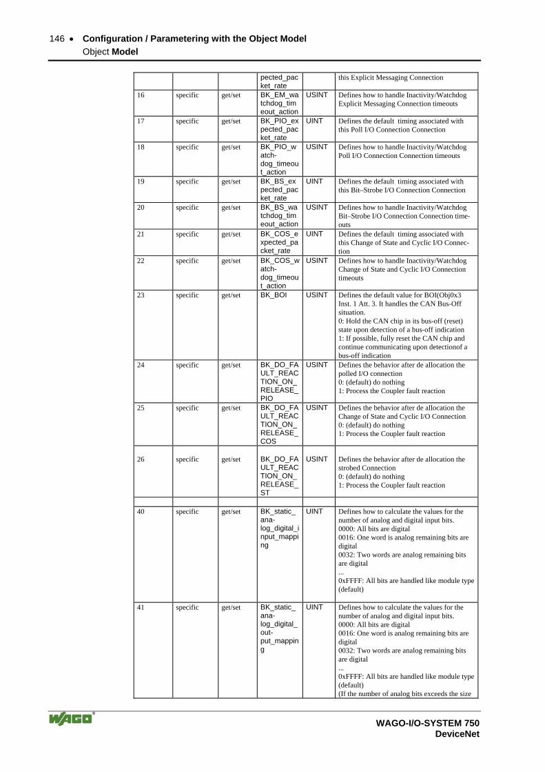
146 • Configuration / Parametering with the Object Model Object Model
WAGO-I/O-SYSTEM 750 DeviceNet
pected_packet_rate
this Explicit Messaging Connection
16 specific get/set BK_EM_watchdog_timeout_action
USINT Defines how to handle Inactivity/Watchdog Explicit Messaging Connection timeouts
17 specific get/set BK_PIO_expected_packet_rate
UINT Defines the default timing associated with this Poll I/O Connection Connection
18 specific get/set BK_PIO_watch-dog_timeout_action
USINT Defines how to handle Inactivity/Watchdog Poll I/O Connection Connection timeouts
19 specific get/set BK_BS_expected_packet_rate
UINT Defines the default timing associated with this Bit–Strobe I/O Connection Connection
20 specific get/set BK_BS_watchdog_timeout_action
USINT Defines how to handle Inactivity/Watchdog Bit–Strobe I/O Connection Connection time-outs
21 specific get/set BK_COS_expected_packet_rate
UINT Defines the default timing associated with this Change of State and Cyclic I/O Connec-tion
22 specific get/set BK_COS_watch-dog_timeout_action
USINT Defines how to handle Inactivity/Watchdog Change of State and Cyclic I/O Connection timeouts
23 specific get/set BK_BOI USINT Defines the default value for BOI(Obj0x3 Inst. 1 Att. 3. It handles the CAN Bus-Off situation. 0: Hold the CAN chip in its bus-off (reset) state upon detection of a bus-off indication 1: If possible, fully reset the CAN chip and continue communicating upon detectionof a bus-off indication
24 specific get/set BK_DO_FAULT_REACTION_ON_RELEASE_PIO
USINT Defines the behavior after de allocation the polled I/O connection 0: (default) do nothing 1: Process the Coupler fault reaction
25 specific get/set BK_DO_FAULT_REACTION_ON_RELEASE_COS
USINT Defines the behavior after de allocation the Change of State and Cyclic I/O Connection 0: (default) do nothing 1: Process the Coupler fault reaction
26 specific get/set BK_DO_FA
ULT_REACTION_ON_RELEASE_ST
USINT Defines the behavior after de allocation the strobed Connection 0: (default) do nothing 1: Process the Coupler fault reaction
40 specific get/set BK_static_
ana-log_digital_input_mapping
UINT Defines how to calculate the values for the number of analog and digital input bits. 0000: All bits are digital 0016: One word is analog remaining bits are digital 0032: Two words are analog remaining bits are digital ... 0xFFFF: All bits are handled like module type (default)
41 specific get/set BK_static_ana-log_digital_out-put_mapping
UINT Defines how to calculate the values for the number of analog and digital input bits. 0000: All bits are digital 0016: One word is analog remaining bits are digital 0032: Two words are analog remaining bits are digital ... 0xFFFF: All bits are handled like module type (default) (If the number of analog bits exceeds the size

Configuration / Parametering with the Object Model • 147 Object Model
WAGO-I/O-SYSTEM 750 DeviceNet
of the process image all bits are mapped to analog bits.
42 specific get/set BK_specific_Coupler_behavior
UINT Defines the Couplers functionality. 0xFFFF: All possible functions are enabled. (resetting a bit to 0 disables the assigned functionality). It is only possible to reduce the functionality. Resetting to „1“ is ignored.
43 specific get/set BK_revision_setting
UINT Defines the Couplers major and minor revi-sion attribute. 0xFFFF: The major and minor revison Attrib-utes are set by the firmware. (This is the default behavior). 0x??00: The minor revison is set to 0. 0x03??: The mjor revison is set to 3. All other values are valid to.
45 specific get BK_Led_Err_Code
UINT I/O LED Error Code
46 specific get BK_Led_Err_Arg
UINT I/O LED Error Argument
Services:
Service Code Service Name Description 0x0E Get_Attribute_Single Used to read a DeviceNet Object attribute
value 0x10 Set_Attribute_Single Used to modify a DeviceNet object attribute
value
4.6.2.1.9 Discrete Input Point Object (0x65):
Instance 0:
Attribute ID
Used in buscoupler
Access rule
Name Data type Description Value
1 required get Revision UINT Revision of the Identity Object, Range 1-65535, class definition upon which the implementation is based.
0x01
2 optional get Max instance
UINT maximum number of instances of an object currently created in this class level of the device
0x256
Description of the instances:
Instance ID Description 1 Reference to the first digital input point 2 Reference to the next digital input point ... 255 Reference to the last possible digital input point
Instance 1 to 255:
Attribute ID
Used in buscoupler
Access rule
Name Data type Description Value
1 dep. on kind of connected modules
get DIPOBJ_ VALUE
BIT digital input bit 0:off 1:on
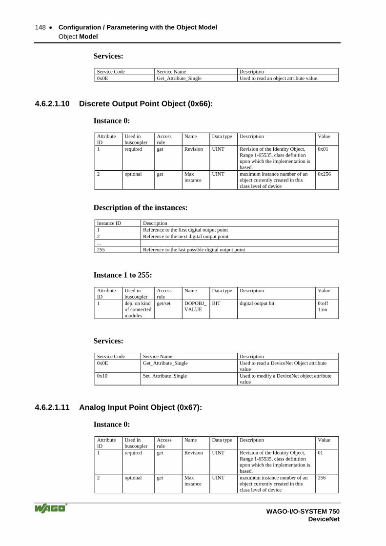
148 • Configuration / Parametering with the Object Model Object Model
WAGO-I/O-SYSTEM 750 DeviceNet
Services:
Service Code Service Name Description 0x0E Get_Attribute_Single Used to read an object attribute value.
4.6.2.1.10 Discrete Output Point Object (0x66):
Instance 0:
Attribute ID
Used in buscoupler
Access rule
Name Data type Description Value
1 required get Revision UINT Revision of the Identity Object, Range 1-65535, class definition upon which the implementation is based.
0x01
2 optional get Max instance
UINT maximum instance number of an object currently created in this class level of device
0x256
Description of the instances:
Instance ID Description 1 Reference to the first digital output point 2 Reference to the next digital output point ... 255 Reference to the last possible digital output point
Instance 1 to 255:
Attribute ID
Used in buscoupler
Access rule
Name Data type Description Value
1 dep. on kind of connected modules
get/set DOPOBJ_ VALUE
BIT digital output bit 0:off 1:on
Services:
Service Code Service Name Description 0x0E Get_Attribute_Single Used to read a DeviceNet Object attribute
value 0x10 Set_Attribute_Single Used to modify a DeviceNet object attribute
value
4.6.2.1.11 Analog Input Point Object (0x67):
Instance 0:
Attribute ID
Used in buscoupler
Access rule
Name Data type Description Value
1 required get Revision UINT Revision of the Identity Object, Range 1-65535, class definition upon which the implementation is based.
01
2 optional get Max instance
UINT maximum instance number of an object currently created in this class level of device
256

Configuration / Parametering with the Object Model • 149 Object Model
WAGO-I/O-SYSTEM 750 DeviceNet
Description of the instances:
Instance ID Description 1 reference to the first analog input point 2 reference to the next analog input point ... 255 reference to the last possible analog input point
Instance 1 to 255:
Attribute ID
Used in buscoupler
Access rule
Name Data type Description Value
1 dep. on kind of connected modules
get AIPOBJ_ VALUE
Array of Byte
Input data aktual input Values
2 dep. on kind of connected modules
get AIPOBJ_ VALUE
USINT Input data length Number of Bytes
Services:
Service Code Service Name Description 0x0E Get_Attribute_Single Used to read a DeviceNet Object attribute
value 0x10 Set_Attribute_Single Used to modify a DeviceNet object attribute
value
4.6.2.1.12 Analog Output Point Object (0x68):
Instance 0:
Attribute ID
Used in buscoupler
Access rule
Name Data type Description Value
1 required get Revision UINT Revision of the Identity Object, Range 1-65535, class definition upon which the implementation is based.
01
2 optional get Max instance
UINT maximum instance number of an object currently created in this class level of device
256
Description of the instances:
Instance ID Description 1 reference to the first analog output point 2 reference to the next analog output point ... 255 reference to the last possible analog output point
Instance 1 to 255:
Attribute ID
Used in buscoupler
Access rule
Name Data type Description Value
1 dep. on kind of connected modules
get AOPOBJ_ VALUE
Array of Byte
output data actual output value
2 dep. on kind of connected
get AOPOBJ_ VALUE
USINT output data length number of Bytes

150 • Configuration / Parametering with the Object Model Object Model
WAGO-I/O-SYSTEM 750 DeviceNet
modules
Services:
Service Code Service Name Description 0x0E Get_Attribute_Single Used to read a DeviceNet Object attribute
value 0x10 Set_Attribute_Single Used to modify a DeviceNet object attribute
value

Configuration / Parametering with the Object Model • 151 Object Model
WAGO-I/O-SYSTEM 750 DeviceNet
4.6.2.2 Supplement to the Object Model for Controller 750-806
4.6.2.2.1 Bit-Strobe
• Consumed Path changeable (Discrete Output Point (class 0x66) or 0 valid)
• Produced-Path changeable like a poll connection (if data size more than 8 bytes, only the first 8 bytes are transmitted)
4.6.2.2.2 Dynamic Assembly
• Two dynamic assembly instances possible (instance 100 and 101)
Attribute ID Used in buscoupler
Acces Rule
Name DeviceNet data type
Description of attribute Semantics of values
1 Required Get Number of Members in List
UINT Max.51 members possible
2 Get/Set Member List Array of Struct The member list is an array of DeviceNet paths
Member Data Description
UINT Size of member data Size in bits
Member Path Size
UINT Size of member path Size in bytes
Required
Member Path (**)
EPATH
3 Required Get/Set Data Array of Byte (**) Descrition of the MemberPath: 0x20 CC 0x24 II 0x30 AA CC: class II: instance AA: attribute The following classes / instances / attributes are possible: class:100 instance 1 attribute 5 (ProcessState) class:100 instance 1 attribute 6 (DNS_i_Trmnldia) class:101 (Discrete Input Point Object) class:102 (Discrete Output Point Object) class:103 (Analog Input Point Object) class:104 (Analog Output Point Object) class:160-173 (PLC variables)
Class Services
Service code Service name Service description 0x0Eh Get_Attribute_Single Used to read an Object attribute value 0x08h Create Instantiates an Assembly object within a
specified class. Response contains ins-tance number.
Instance Services
Service code Service name Service description 0x0Eh Get_Attribute_Single Used to read an Object attribute value 0x10h Set_Attribute_Single Modifies an attribute value 0x09h Delete Deletes an assembly object and releases
all associated resources
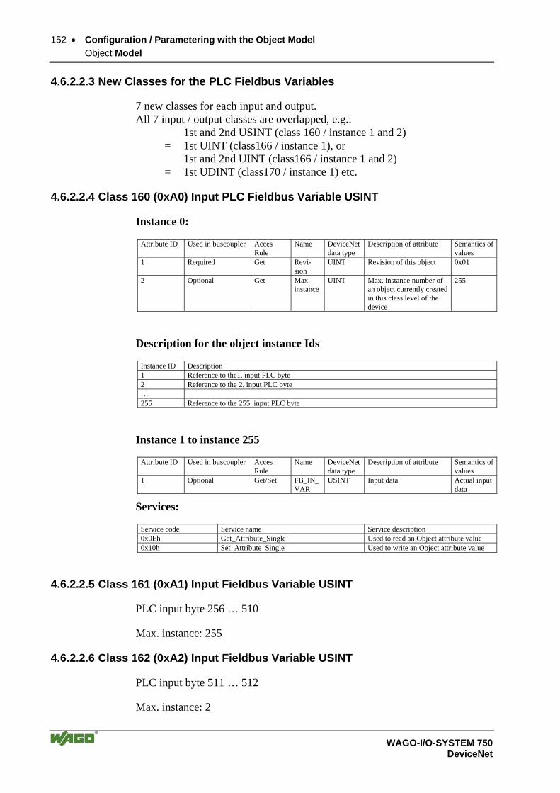
152 • Configuration / Parametering with the Object Model Object Model
WAGO-I/O-SYSTEM 750 DeviceNet
4.6.2.2.3 New Classes for the PLC Fieldbus Variables
7 new classes for each input and output. All 7 input / output classes are overlapped, e.g.: 1st and 2nd USINT (class 160 / instance 1 and 2) = 1st UINT (class166 / instance 1), or 1st and 2nd UINT (class166 / instance 1 and 2) = 1st UDINT (class170 / instance 1) etc.
4.6.2.2.4 Class 160 (0xA0) Input PLC Fieldbus Variable USINT
Instance 0:
Attribute ID Used in buscoupler Acces Rule
Name DeviceNet data type
Description of attribute Semantics of values
1 Required Get Revi-sion
UINT Revision of this object 0x01
2 Optional Get Max. instance
UINT Max. instance number of an object currently created in this class level of the device
255
Description for the object instance Ids
Instance ID Description 1 Reference to the1. input PLC byte 2 Reference to the 2. input PLC byte … 255 Reference to the 255. input PLC byte
Instance 1 to instance 255
Attribute ID Used in buscoupler Acces Rule
Name DeviceNet data type
Description of attribute Semantics of values
1 Optional Get/Set FB_IN_VAR
USINT Input data Actual input data
Services:
Service code Service name Service description 0x0Eh Get_Attribute_Single Used to read an Object attribute value 0x10h Set_Attribute_Single Used to write an Object attribute value
4.6.2.2.5 Class 161 (0xA1) Input Fieldbus Variable USINT
PLC input byte 256 … 510
Max. instance: 255
4.6.2.2.6 Class 162 (0xA2) Input Fieldbus Variable USINT
PLC input byte 511 … 512
Max. instance: 2

Configuration / Parametering with the Object Model • 153 Object Model
WAGO-I/O-SYSTEM 750 DeviceNet
4.6.2.2.7 Class 163 (0xA3) Output Fieldbus Variable USINT
Attribute ID Used in buscoupler Acces Rule Name DeviceNet data type
Description of attribute Semantics of values
1 Required Get Revision UINT Revision of this object 0x01 2 Optional Get Max. ins-
tance UINT Max. instance number
of an object currently created in this class level of the device
255
Description for the object instance Ids
Instance ID Description 1 Reference to the 1. PLC output byte 2 Reference to the 2. PLC output byte … 255 Reference to the 255. PLC output byte
Instance 1 to instance 255:
Attribute ID
Used in buscoupler Acces Rule Name DeviceNet data type
Description of attribute Semantics of values
1 Optional Get FB_OUT_VAR
USINT Output data Actual output data
Services:
Service code Service name Service description 0x0Eh Get_Attribute_Single Used to read an Object attribute value
4.6.2.2.8 Class 164 (0xA4) Output Fieldbus Variable USINT
PLC output byte 256 … 510
Max. instance: 255
4.6.2.2.9 Class 165 (0xA5) Output Fieldbus Variable USINT
PLC output byte 511 … 512
Max. instance: 2
4.6.2.2.10 Class 166 (0xA6) Input Fieldbus Variable UINT
PLC input byte 1..255
Max. instance: 255
4.6.2.2.11 Class 167 (0xA7) Input Fieldbus Variable UINT
PLC input byte 256
Max. instance: 1

154 • Configuration / Parametering with the Object Model Object Model
WAGO-I/O-SYSTEM 750 DeviceNet
4.6.2.2.12 Class 168 (0xA8) Output Fieldbus Variable UINT
PLC output byte 1..255
Max. instance: 255
4.6.2.2.13 Class 169 (0xA9) Output Fieldbus Variable UINT
PLC output byte 256
Max. instance: 1
4.6.2.2.14 Class 170 (0xAA) Input Fieldbus Variable UDINT
PLC input byte 1..128
Max. instance: 128
4.6.2.2.15 Class 171 (0xAB) Input Fieldbus Variable UDINT
PLC input byte 1..128
Max. instance: 128
Starts with 2 bytes offset (the 2nd and 3rd UINT (class166 / instance 2 and 3) = 1st UDINT (class171 / instance 1) etc.)
4.6.2.2.16 Class 172 (0xAC) Output Fieldbus Variable UDINT
PLC output byte 1..128
Max. instance: 128
4.6.2.2.17 Class 173 (0xAD) Output Fieldbus Variable UDINT
PLC output byte 1..128
Max. instance: 128
Starts with 2 bytes offset (the 2nd and 3rd UINT (class168 / instance 2 and 3) = 1st UDINT (class173 / instance 1) etc.)
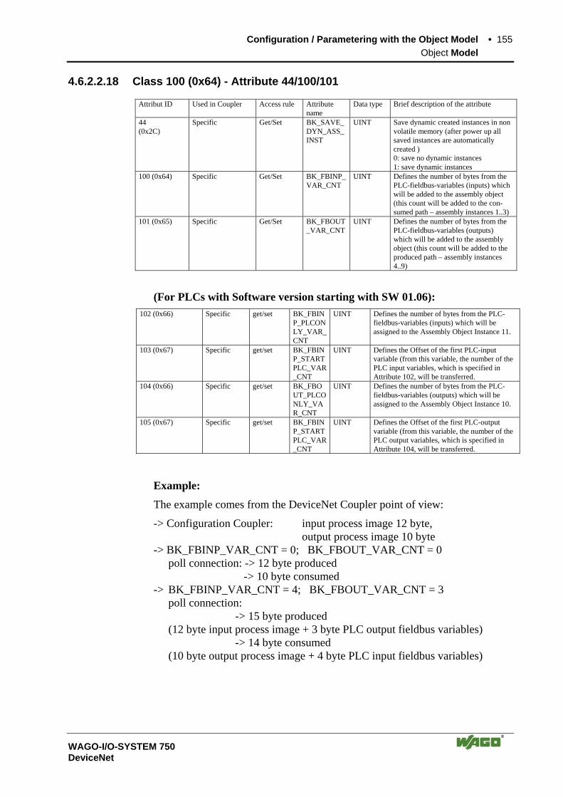
Configuration / Parametering with the Object Model • 155 Object Model
WAGO-I/O-SYSTEM 750 DeviceNet
4.6.2.2.18 Class 100 (0x64) - Attribute 44/100/101
Attribut ID Used in Coupler Access rule Attribute name
Data type Brief description of the attribute
44 (0x2C)
Specific Get/Set BK_SAVE_DYN_ASS_INST
UINT Save dynamic created instances in non volatile memory (after power up all saved instances are automatically created ) 0: save no dynamic instances 1: save dynamic instances
100 (0x64) Specific Get/Set BK_FBINP_VAR_CNT
UINT Defines the number of bytes from the PLC-fieldbus-variables (inputs) which will be added to the assembly object (this count will be added to the con-sumed path – assembly instances 1..3)
101 (0x65) Specific Get/Set BK_FBOUT_VAR_CNT
UINT Defines the number of bytes from the PLC-fieldbus-variables (outputs) which will be added to the assembly object (this count will be added to the produced path – assembly instances 4..9)
(For PLCs with Software version starting with SW 01.06): 102 (0x66) Specific get/set BK_FBIN
P_PLCONLY_VAR_CNT
UINT Defines the number of bytes from the PLC-fieldbus-variables (inputs) which will be assigned to the Assembly Object Instance 11.
103 (0x67) Specific get/set BK_FBINP_STARTPLC_VAR_CNT
UINT Defines the Offset of the first PLC-input variable (from this variable, the number of the PLC input variables, which is specified in Attribute 102, will be transferred.
104 (0x66) Specific get/set BK_FBOUT_PLCONLY_VAR_CNT
UINT Defines the number of bytes from the PLC-fieldbus-variables (outputs) which will be assigned to the Assembly Object Instance 10.
105 (0x67) Specific get/set BK_FBINP_STARTPLC_VAR_CNT
UINT Defines the Offset of the first PLC-output variable (from this variable, the number of the PLC output variables, which is specified in Attribute 104, will be transferred.
Example:
The example comes from the DeviceNet Coupler point of view:
-> Configuration Coupler: input process image 12 byte, output process image 10 byte -> BK_FBINP_VAR_CNT = 0; BK_FBOUT_VAR_CNT = 0 poll connection: -> 12 byte produced -> 10 byte consumed -> BK_FBINP_VAR_CNT = 4; BK_FBOUT_VAR_CNT = 3 poll connection: -> 15 byte produced (12 byte input process image + 3 byte PLC output fieldbus variables) -> 14 byte consumed (10 byte output process image + 4 byte PLC input fieldbus variables)

156 • Configuration / Parametering with the Object Model Object Model
WAGO-I/O-SYSTEM 750 DeviceNet
4.6.2.2.19 Identity Class 1 (0x01)
Instance 1:
Attribut ID Used in Coupler Access rule Attribute name Data type Description of the attribute Default Value
10 (0x0A) required Get/Set Heartbeat Interval
USINT Interval between 2 Heart-beat messages in seconds
0
4.6.2.2.20 Connection Object (0x05)
Description of the instances:
Instance ID Description 1 ... 4 ... 5 6 7 8 9
References dynamic Connection
10 11 12 13 14
References I/O Connection
4.6.2.2.21 Additional Assembly Instances 10 and 11
In addition to the (static) assemblies (1 ... 9) that are permanently pre-programmed in the device, the Controller has the assembly instances 10 and 11. These simplify and speed up the transmission of the input and output image of the PLC variable from the fieldbus Controller to the master.
Description of the instances:
Instance ID
Description
1 ... 9 .... 10 References to the process image containing PLC output variables. 11 References to the process image containing PLC input variables.
Instance 10:
Attribute ID
Used in buscoupler
Access rule
Name Data type Description Value
3 optional get PLC output variables
Array of Byte
process image, collection of all PLC output variables
Instance 11:
Attribute ID
Used in buscoupler
Access rule
Name Data type Description Value
3 optional get PLC input variables
Array of Byte
process image, collection of all PLC input variables

Configuration / Parametering with the Object Model • 157 Object Model
WAGO-I/O-SYSTEM 750 DeviceNet
(For PLCs with software version before SW 01.06):
PLC Output (I/O Assembly Instance 10):
Only the PLC output variables are transmitted via the corresponding I/O mes-sage connection. The data length is equivalent to the value in class 100 / in-stance 1 / attribute 101 (BK_FBOUT_ VAR_CNT).
PLC Input (I/O Assembly Instance 11):
Only the PLC input variables are transmitted via the corresponding I/O mes-sage connection. The data length is equivalent to the value in class 100 / in-stance 1 / attribute 100 (BK_FBIN_ VAR_CNT).
(For PLCs from software version SW 01.06):
PLC Output (I/O Assembly Instance 10):
Only the PLC output variables are transmitted via the corresponding I/O mes-sage connection. The data length is equivalent to the value in class 100 / in-stance 1 / attribute 104 (BK_FBOUT_ PLCONLY_VAR_CNT). The first PLC transfer byte is defined by the value in class 100 / instance 1 / attribute 105 (BK_FBOUT_STARTPLC_VAR_CNT).
PLC Input (I/O Assembly Instance 11):
Only the PLC input variables are transmitted via the corresponding I/O mes-sage connection. The data length is equivalent to the value in class 100 / in-stance 1 / attribute 102 (BK_FBINP_PLCONLY_ VAR_CNT). The first PLC transfer byte is defined by the value in class 100 / instance 1 / attribute 103 (BK_FBIN_STARTPLC_VAR_CNT).

158 • I/O Modules
WAGO-I/O-SYSTEM 750 DeviceNet
5 I/O Modules 5.1 Overview
All listed bus modules, in the overview below, are available for modular ap-plications with the WAGO-I/O-SYSTEM 750. For detailed information on the I/O modules and the module variations, please refer to the manuals for the I/O modules. You will find these manuals on CD ROM „ELECTRONICC Tools and Docs“ (Item-no.: 0888-0412) or on the web pages: www.wago.com Service Download Documentation.
More Information Current information on the modular WAGO-I/O-SYSTEM is available in the Internet under: www.wago.com
5.1.1 Digital Input Modules
DI DC 5 V
750-414 4 Channel, DC 5 V, 0.2 ms, 2- to 3-conductor connection, high-side switching
DI DC 5(12) V
753-434 8 Channel, DC 5(12) V, 0.2 ms, 1-conductor connection, high-side switching
DI DC 24 V
750-400, 753-400 2 Channel, DC 24 V, 3.0 ms, 2- to 4-conductor connection; high-side switching
750-401, 753-401 2 Channel, DC 24 V, 0.2 ms, 2- to 4-conductor connection; high-side switching
750-410, 753-410 2 Channel, DC 24 V, 3.0 ms, 2- to 4-conductor connection; high-side switching
750-411, 753-411 2 Channel, DC 24 V, 0.2 ms, 2- to 4-conductor connection; high-side switching
750-418, 753-418 2 Channel, DC 24 V, 3.0 ms, 2- to 3-conductor connection; high-side switching; diagnostic
750-419 2 Channel, DC 24 V, 3.0 ms, 2- to 3-conductor connection; high-side switching; diagnostic
750-421, 753-421 2 Channel, DC 24 V, 3.0 ms, 2- to 3-conductor connection; high-side switching; diagnostic
750-402, 753-402 4 Channel, DC 24 V, 3.0 ms, 2- to 3-conductor connection; high-side switching
750-432, 753-432 4 Channel, DC 24 V, 3.0 ms, 2-conductor connection; high-side switching
750-403, 753-403 4 Channel, DC 24 V, 0.2 ms, 2- to 3-conductor connection; high-side switching
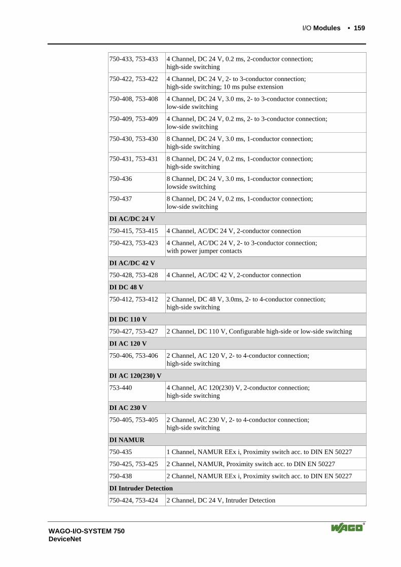
I/O Modules • 159
WAGO-I/O-SYSTEM 750 DeviceNet
750-433, 753-433 4 Channel, DC 24 V, 0.2 ms, 2-conductor connection; high-side switching
750-422, 753-422 4 Channel, DC 24 V, 2- to 3-conductor connection; high-side switching; 10 ms pulse extension
750-408, 753-408 4 Channel, DC 24 V, 3.0 ms, 2- to 3-conductor connection; low-side switching
750-409, 753-409 4 Channel, DC 24 V, 0.2 ms, 2- to 3-conductor connection; low-side switching
750-430, 753-430 8 Channel, DC 24 V, 3.0 ms, 1-conductor connection; high-side switching
750-431, 753-431 8 Channel, DC 24 V, 0.2 ms, 1-conductor connection; high-side switching
750-436 8 Channel, DC 24 V, 3.0 ms, 1-conductor connection; lowside switching
750-437 8 Channel, DC 24 V, 0.2 ms, 1-conductor connection; low-side switching
DI AC/DC 24 V
750-415, 753-415 4 Channel, AC/DC 24 V, 2-conductor connection
750-423, 753-423 4 Channel, AC/DC 24 V, 2- to 3-conductor connection; with power jumper contacts
DI AC/DC 42 V
750-428, 753-428 4 Channel, AC/DC 42 V, 2-conductor connection
DI DC 48 V
750-412, 753-412 2 Channel, DC 48 V, 3.0ms, 2- to 4-conductor connection; high-side switching
DI DC 110 V
750-427, 753-427 2 Channel, DC 110 V, Configurable high-side or low-side switching
DI AC 120 V
750-406, 753-406 2 Channel, AC 120 V, 2- to 4-conductor connection; high-side switching
DI AC 120(230) V
753-440 4 Channel, AC 120(230) V, 2-conductor connection; high-side switching
DI AC 230 V
750-405, 753-405 2 Channel, AC 230 V, 2- to 4-conductor connection; high-side switching
DI NAMUR
750-435 1 Channel, NAMUR EEx i, Proximity switch acc. to DIN EN 50227
750-425, 753-425 2 Channel, NAMUR, Proximity switch acc. to DIN EN 50227
750-438 2 Channel, NAMUR EEx i, Proximity switch acc. to DIN EN 50227
DI Intruder Detection
750-424, 753-424 2 Channel, DC 24 V, Intruder Detection

160 • I/O Modules
WAGO-I/O-SYSTEM 750 DeviceNet
5.1.2 Digital Output Modules
DO DC 5 V
750-519 4 Channel, DC 5 V, 20mA, short-circuit-protected; high-side switching
DO DC 12(14) V
753-534 8 Channel, DC 12(14) V, 1A, short-circuit-protected; high-side switch-ing
DO DC 24 V
750-501, 753-501 2 Channel, DC 24 V, 0.5 A, short-circuit-protected; high-side switching
750-502, 753-502 2 Channel, DC 24 V, 2.0 A, short-circuit-protected; high-side switching
750-506, 753-506 2 Channel, DC 24 V, 0.5 A, short-circuit-protected; high-side switching; with diagnostics
750-507, 753-507 2 Channel, DC 24 V, 2.0 A, short-circuit-protected; high-side switching; with diagnostics; No longer available, replaced by 750-508
750-508 2 Channel, DC 24 V, 2.0 A, short-circuit-protected; high-side switching; with diagnostics; Replacement for 750-508
750-535 2 Channel, DC 24 V, EEx i, short-circuit-protected; PNP-positive switching
750-504, 753-504 4 Channel, DC 24 V, 0.5 A, short-circuit-protected; high-side switching
750-531, 753-531 4 Channel, DC 24 V, 0.5 A, short-circuit-protected; high-side switching
750-516, 753-516 4 Channel, DC 24 V, 0.5 A, short-circuit-protected; low-side switching
750-530, 753-530 8 Channel, DC 24 V, 0.5 A, short-circuit-protected; high-side switching
750-537 8 Channel, DC 24 V, 0.5 A, short-circuit-protected; high-side switching; with diagnostics
750-536 8 Channel, DC 24 V, 0.5 A, short-circuit-protected; low-side switching
DO AC 120(230) V
753-540 4 Channel, AC 120(230) V, 0.25 A, short-circuit-protected; high-side switching
DO AC/DC 230 V
750-509, 753-509 2 Channel Solid State Relay, AC/DC 230 V, 300 mA
750-522 2 Channel Solid State Relay, AC/DC 230 V, 500 mA, 3 A (< 30 s)
DO Relay
750-523 1 Channel, AC 230 V, AC 16 A, isolated output, 1 make contact, bista-ble, manual operation
750-514, 753-514 2 Channel, AC 125 V , AC 0.5 A , DC 30 V, DC 1 A, isolated outputs, 2 changeover contacts
750-517, 753-517 2 Channel, AC 230 V, 1 A, isolated outputs, 2 changeover contacts
750-512, 753-512 2 Channel, AC 230 V, DC 30 V, AC/DC 2 A, non-floating, 2 make con-tacts
750-513, 753-513 2 Channel, AC 230 V, DC 30 V, AC/DC 2 A, isolated outputs, 2 make contacts
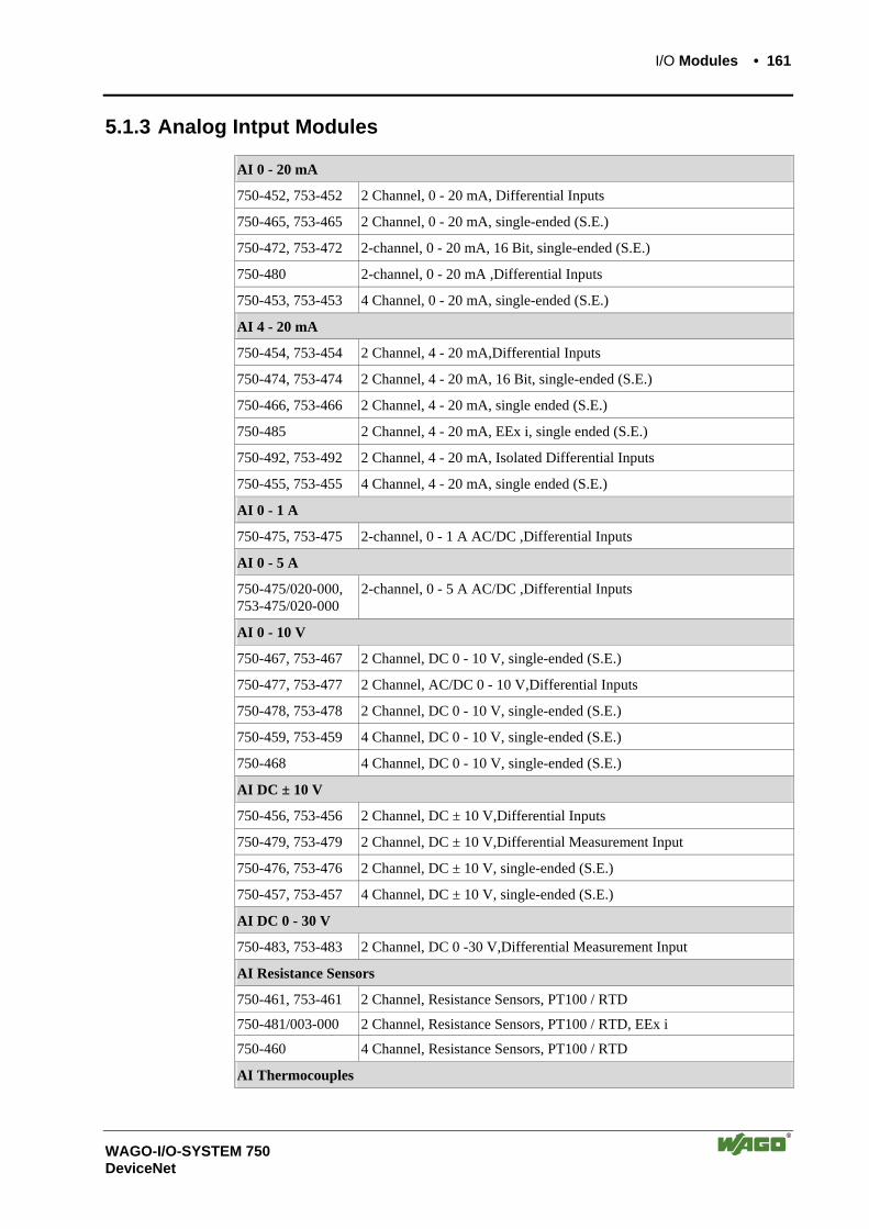
I/O Modules • 161
WAGO-I/O-SYSTEM 750 DeviceNet
5.1.3 Analog Intput Modules
AI 0 - 20 mA
750-452, 753-452 2 Channel, 0 - 20 mA, Differential Inputs
750-465, 753-465 2 Channel, 0 - 20 mA, single-ended (S.E.)
750-472, 753-472 2-channel, 0 - 20 mA, 16 Bit, single-ended (S.E.)
750-480 2-channel, 0 - 20 mA ,Differential Inputs
750-453, 753-453 4 Channel, 0 - 20 mA, single-ended (S.E.)
AI 4 - 20 mA
750-454, 753-454 2 Channel, 4 - 20 mA,Differential Inputs
750-474, 753-474 2 Channel, 4 - 20 mA, 16 Bit, single-ended (S.E.)
750-466, 753-466 2 Channel, 4 - 20 mA, single ended (S.E.)
750-485 2 Channel, 4 - 20 mA, EEx i, single ended (S.E.)
750-492, 753-492 2 Channel, 4 - 20 mA, Isolated Differential Inputs
750-455, 753-455 4 Channel, 4 - 20 mA, single ended (S.E.)
AI 0 - 1 A
750-475, 753-475 2-channel, 0 - 1 A AC/DC ,Differential Inputs
AI 0 - 5 A
750-475/020-000, 753-475/020-000
2-channel, 0 - 5 A AC/DC ,Differential Inputs
AI 0 - 10 V
750-467, 753-467 2 Channel, DC 0 - 10 V, single-ended (S.E.)
750-477, 753-477 2 Channel, AC/DC 0 - 10 V,Differential Inputs
750-478, 753-478 2 Channel, DC 0 - 10 V, single-ended (S.E.)
750-459, 753-459 4 Channel, DC 0 - 10 V, single-ended (S.E.)
750-468 4 Channel, DC 0 - 10 V, single-ended (S.E.)
AI DC ± 10 V
750-456, 753-456 2 Channel, DC ± 10 V,Differential Inputs
750-479, 753-479 2 Channel, DC ± 10 V,Differential Measurement Input
750-476, 753-476 2 Channel, DC ± 10 V, single-ended (S.E.)
750-457, 753-457 4 Channel, DC ± 10 V, single-ended (S.E.)
AI DC 0 - 30 V
750-483, 753-483 2 Channel, DC 0 -30 V,Differential Measurement Input
AI Resistance Sensors
750-461, 753-461 2 Channel, Resistance Sensors, PT100 / RTD
750-481/003-000 2 Channel, Resistance Sensors, PT100 / RTD, EEx i
750-460 4 Channel, Resistance Sensors, PT100 / RTD
AI Thermocouples
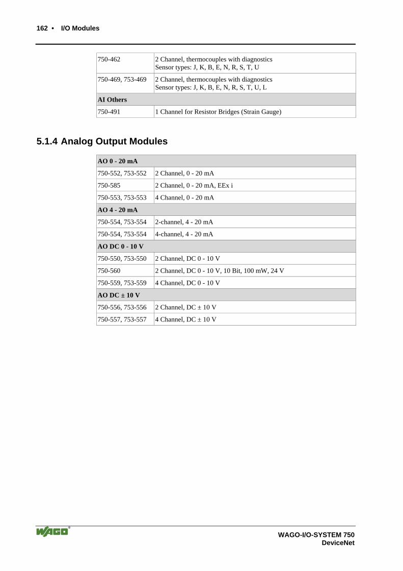
162 • I/O Modules
WAGO-I/O-SYSTEM 750 DeviceNet
750-462 2 Channel, thermocouples with diagnostics Sensor types: J, K, B, E, N, R, S, T, U
750-469, 753-469 2 Channel, thermocouples with diagnostics Sensor types: J, K, B, E, N, R, S, T, U, L
AI Others
750-491 1 Channel for Resistor Bridges (Strain Gauge)
5.1.4 Analog Output Modules
AO 0 - 20 mA
750-552, 753-552 2 Channel, 0 - 20 mA
750-585 2 Channel, 0 - 20 mA, EEx i
750-553, 753-553 4 Channel, 0 - 20 mA
AO 4 - 20 mA
750-554, 753-554 2-channel, 4 - 20 mA
750-554, 753-554 4-channel, 4 - 20 mA
AO DC 0 - 10 V
750-550, 753-550 2 Channel, DC 0 - 10 V
750-560 2 Channel, DC 0 - 10 V, 10 Bit, 100 mW, 24 V
750-559, 753-559 4 Channel, DC 0 - 10 V
AO DC ± 10 V
750-556, 753-556 2 Channel, DC ± 10 V
750-557, 753-557 4 Channel, DC ± 10 V

I/O Modules • 163
WAGO-I/O-SYSTEM 750 DeviceNet
5.1.5 Special Modules
Counter Modules
750-404, 753-404 Up / Down Counter, DC 24 V, 100 kHz
750-638, 753-638 2 Channel, Up / Down Counter, DC 24 V/ 16Bit / 500 Hz
Frequency Measuring
750-404/000-003, 753-404/000-003
Frequency Measuring
Pulse Width Module
750-511 2-channel Pulse Width Module, DC 24 V, short-circuit-protected, high-side switching
Distance and Angle Measurement Modules
750-630 SSI Transmitter Interface
750-631 Incremental Encor Interface, TTL level squarewave
750-634 Incremental Encor Interface, DC 24 V
750-637 Incremental Encor Interface RS 422, cam outputs
750-635, 753-635 Digital Pulse Interface
Serial Interfaces
750-650, 753 Serial Interface RS 232 C
750-653, 753 Serial Interface RS 485
750-651 TTY-Serial Interface, 20 mA Current Loop
750-654 Data Exchange Module
DALI / DSI Master Module
750-641 DALI / DSI Master Module
AS interface Master Module
750-655 AS interface Master Module
Radio Receiver Module
750-642 Radio Receiver EnOcean
MP Bus Master Module
750-643 MP Bus (Multi Point Bus) Master Module
Vibration Monitoring
750-645 2-Channel Vibration Velocity / Bearing Condition Monitoring VIB I/O
PROFIsafe Modules
750-660/000-001 8FDI 24V DC PROFIsafe 750-665/000-001 4FDO 0.5A / 4FDI 24V DC PROFIsafe 750-666/000-001 1FDO 10A / 2FDO 0.5A / 2FDI 24V PROFIsafe
RTC Module
750-640 RTC Module
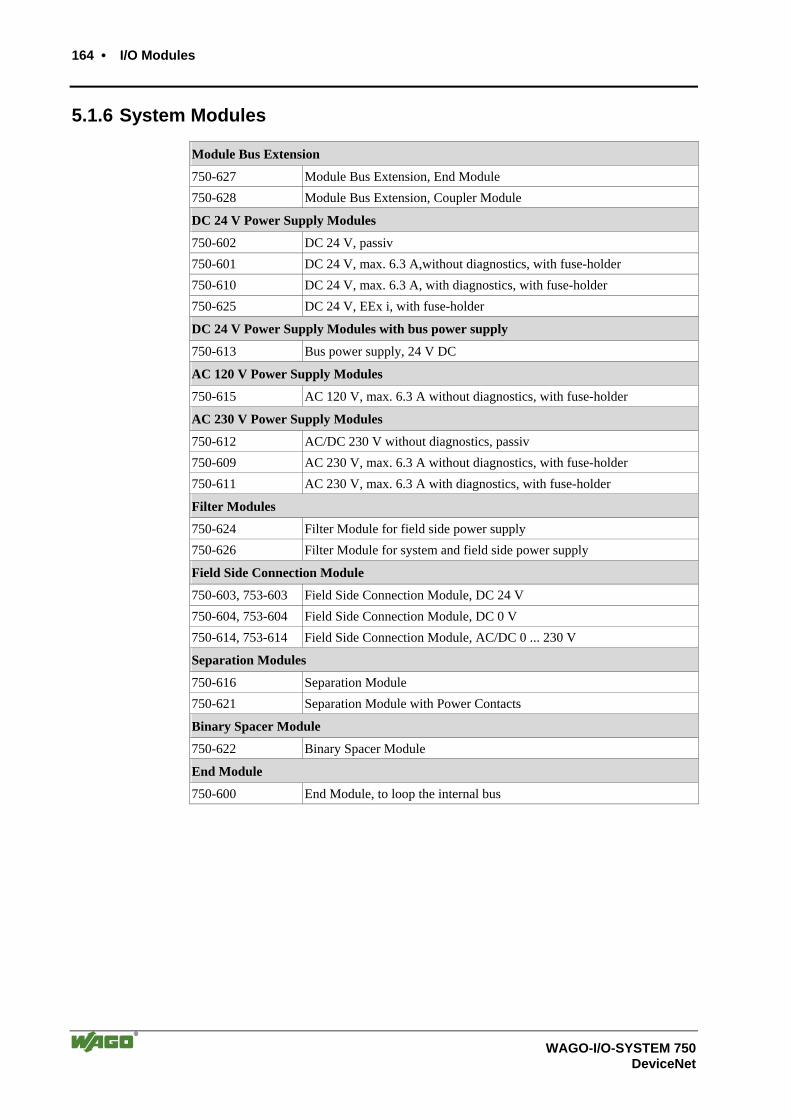
164 • I/O Modules
WAGO-I/O-SYSTEM 750 DeviceNet
5.1.6 System Modules
Module Bus Extension
750-627 Module Bus Extension, End Module 750-628 Module Bus Extension, Coupler Module
DC 24 V Power Supply Modules
750-602 DC 24 V, passiv 750-601 DC 24 V, max. 6.3 A,without diagnostics, with fuse-holder 750-610 DC 24 V, max. 6.3 A, with diagnostics, with fuse-holder 750-625 DC 24 V, EEx i, with fuse-holder
DC 24 V Power Supply Modules with bus power supply
750-613 Bus power supply, 24 V DC
AC 120 V Power Supply Modules
750-615 AC 120 V, max. 6.3 A without diagnostics, with fuse-holder
AC 230 V Power Supply Modules
750-612 AC/DC 230 V without diagnostics, passiv 750-609 AC 230 V, max. 6.3 A without diagnostics, with fuse-holder 750-611 AC 230 V, max. 6.3 A with diagnostics, with fuse-holder
Filter Modules
750-624 Filter Module for field side power supply 750-626 Filter Module for system and field side power supply
Field Side Connection Module
750-603, 753-603 Field Side Connection Module, DC 24 V 750-604, 753-604 Field Side Connection Module, DC 0 V 750-614, 753-614 Field Side Connection Module, AC/DC 0 ... 230 V
Separation Modules
750-616 Separation Module 750-621 Separation Module with Power Contacts
Binary Spacer Module
750-622 Binary Spacer Module
End Module
750-600 End Module, to loop the internal bus

I/O Modules • 165 Process Data Architecture for DeviceNet
WAGO-I/O-SYSTEM 750 DeviceNet
5.2 Process Data Architecture for DeviceNet With some I/O modules, the structure of the process data is fieldbus specific.
In the case of a DeviceNet coupler/controller, the process image uses a byte structure (without word alignment). The internal mapping method for data greater than one byte conforms to the Intel format.
The following section describes the process image for various WAGO-I/O-SYSTEM 750 and 753 I/O modules when using a DeviceNet cou-pler/controller.
Note Depending on the specific position of an I/O module in the fieldbus node, the process data of all previous byte or bit-oriented modules must be taken into account to determine its location in the process data map.
For the PFC process image of the programmable fieldbus controller is the structure of the process data mapping identical.
5.2.1 Digital Input Modules
Digital input modules supply one bit of data per channel to specify the signal state for the corresponding channel. These bits are mapped into the Input Process Image.
When analog input modules are also present in the node, the digital data is al-ways appended after the analog data in the Input Process Image, grouped into bytes.
Some digital modules have an additional diagnostic bit per channel in the In-put Process Image. The diagnostic bit is used for detecting faults that occur (e.g., wire breaks and/or short circuits).
Each input channel seizes one Instance in the Discrete Input Point Object (Class 0x65).
1 Channel Digital Input Module with Diagnostics
750-435
Input Process Image Bit 7 Bit 6 Bit 5 Bit 4 Bit 3 Bit 2 Bit 1 Bit 0
Diagnostic bit S 1
Data bitDI 1
The input modules seize 2 Instances in Class (0x65).
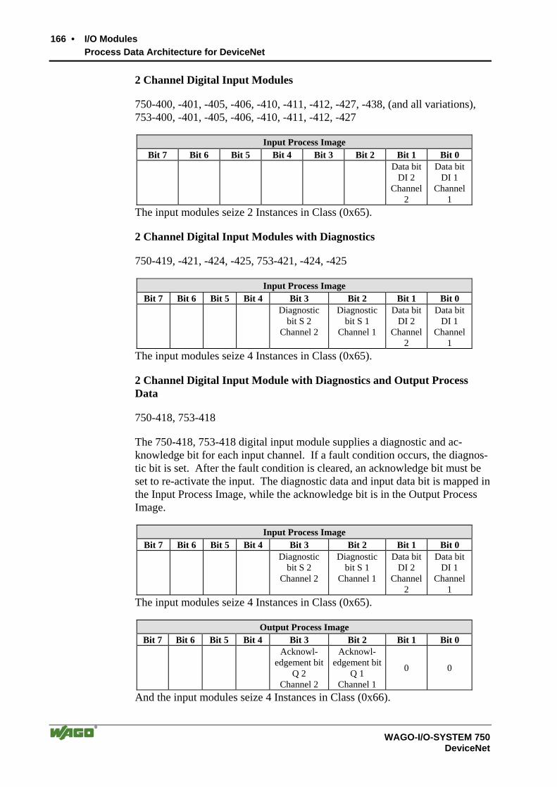
166 • I/O Modules Process Data Architecture for DeviceNet
WAGO-I/O-SYSTEM 750 DeviceNet
2 Channel Digital Input Modules
750-400, -401, -405, -406, -410, -411, -412, -427, -438, (and all variations), 753-400, -401, -405, -406, -410, -411, -412, -427
Input Process Image Bit 7 Bit 6 Bit 5 Bit 4 Bit 3 Bit 2 Bit 1 Bit 0
Data bit DI 2
Channel 2
Data bitDI 1
Channel 1
The input modules seize 2 Instances in Class (0x65).
2 Channel Digital Input Modules with Diagnostics
750-419, -421, -424, -425, 753-421, -424, -425
Input Process Image Bit 7 Bit 6 Bit 5 Bit 4 Bit 3 Bit 2 Bit 1 Bit 0
Diagnostic bit S 2
Channel 2
Diagnostic bit S 1
Channel 1
Data bit DI 2
Channel 2
Data bit DI 1
Channel 1
The input modules seize 4 Instances in Class (0x65).
2 Channel Digital Input Module with Diagnostics and Output Process Data
750-418, 753-418
The 750-418, 753-418 digital input module supplies a diagnostic and ac-knowledge bit for each input channel. If a fault condition occurs, the diagnos-tic bit is set. After the fault condition is cleared, an acknowledge bit must be set to re-activate the input. The diagnostic data and input data bit is mapped in the Input Process Image, while the acknowledge bit is in the Output Process Image.
Input Process Image Bit 7 Bit 6 Bit 5 Bit 4 Bit 3 Bit 2 Bit 1 Bit 0
Diagnostic bit S 2
Channel 2
Diagnostic bit S 1
Channel 1
Data bit DI 2
Channel 2
Data bit DI 1
Channel 1
The input modules seize 4 Instances in Class (0x65).
Output Process Image Bit 7 Bit 6 Bit 5 Bit 4 Bit 3 Bit 2 Bit 1 Bit 0
Acknowl-edgement bit
Q 2 Channel 2
Acknowl-edgement bit
Q 1 Channel 1
0 0
And the input modules seize 4 Instances in Class (0x66).

I/O Modules • 167 Process Data Architecture for DeviceNet
WAGO-I/O-SYSTEM 750 DeviceNet
4 Channel Digital Input Modules
750-402, -403, -408, -409, -414, -415, -422, -423, -428, -432, -433, 753-402, -403, -408, -409, -415, -422, -423, -428, -432, -433, -440
Input Process Image Bit 7 Bit 6 Bit 5 Bit 4 Bit 3 Bit 2 Bit 1 Bit 0
Data bitDI 4
Channel 4
Data bit DI 3
Channel 3
Data bit DI 2
Channel 2
Data bitDI 1
Channel 1
The input modules seize 4 Instances in Class (0x65).
8 Channel Digital Input Modules
750-430, -431, -436, -437, 753-430, -431, -434
Input Process Image Bit 7 Bit 6 Bit 5 Bit 4 Bit 3 Bit 2 Bit 1 Bit 0
Data bit DI 8
Channel 8
Data bitDI 7
Channel 7
Data bitDI 6
Channel 6
Data bitDI 5
Channel 5
Data bitDI 4
Channel 4
Data bit DI 3
Channel 3
Data bit DI 2
Channel 2
Data bitDI 1
Channel 1
The input modules seize 8 Instances in Class (0x65).
5.2.2 Digital Output Modules
Digital output modules use one bit of data per channel to control the output of the corresponding channel. These bits are mapped into the Output Process Im-age.
When analog output modules are also present in the node, the digital image data is always appended after the analog data in the Output Process Image, grouped into bytes.
Each output channel seizes one Instance in the Discrete Output Point Object (Class 0x66).
1 Channel Digital Output Module with Input Process Data
750-523
Input Process Image Bit 7 Bit 6 Bit 5 Bit 4 Bit 3 Bit 2 Bit 1 Bit 0
not
used
Status bit „Manual
Operation“ The output modules seize 2 Instances in Class (0x65).
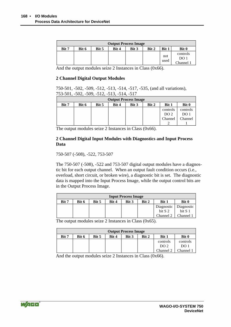
168 • I/O Modules Process Data Architecture for DeviceNet
WAGO-I/O-SYSTEM 750 DeviceNet
Output Process Image Bit 7 Bit 6 Bit 5 Bit 4 Bit 3 Bit 2 Bit 1 Bit 0
not
used
controls DO 1
Channel 1 And the output modules seize 2 Instances in Class (0x66).
2 Channel Digital Output Modules
750-501, -502, -509, -512, -513, -514, -517, -535, (and all variations), 753-501, -502, -509, -512, -513, -514, -517
Output Process Image Bit 7 Bit 6 Bit 5 Bit 4 Bit 3 Bit 2 Bit 1 Bit 0
controls DO 2
Channel 2
controlsDO 1
Channel 1
The output modules seize 2 Instances in Class (0x66).
2 Channel Digital Input Modules with Diagnostics and Input Process Data
750-507 (-508), -522, 753-507
The 750-507 (-508), -522 and 753-507 digital output modules have a diagnos-tic bit for each output channel. When an output fault condition occurs (i.e., overload, short circuit, or broken wire), a diagnostic bit is set. The diagnostic data is mapped into the Input Process Image, while the output control bits are in the Output Process Image.
Input Process Image Bit 7 Bit 6 Bit 5 Bit 4 Bit 3 Bit 2 Bit 1 Bit 0
Diagnostic
bit S 2 Channel 2
Diagnostic bit S 1
Channel 1 The output modules seize 2 Instances in Class (0x65).
Output Process Image Bit 7 Bit 6 Bit 5 Bit 4 Bit 3 Bit 2 Bit 1 Bit 0
controls
DO 2 Channel 2
controls DO 1
Channel 1 And the output modules seize 2 Instances in Class (0x66).

I/O Modules • 169 Process Data Architecture for DeviceNet
WAGO-I/O-SYSTEM 750 DeviceNet
750-506, 753-506
The 750-506, 753-506 digital output module has 2-bits of diagnostic informa-tion for each output channel. The 2-bit diagnostic information can then be de-coded to determine the exact fault condition of the module (i.e., overload, a short circuit, or a broken wire). The 4-bits of diagnostic data are mapped into the Input Process Image, while the output control bits are in the Output Proc-ess Image.
Input Process Image Bit 7 Bit 6 Bit 5 Bit 4 Bit 3 Bit 2 Bit 1 Bit 0
Diagnostic
bit S 3 Channel 2
Diagnostic bit S 2
Channel 2
Diagnostic bit S 1
Channel 1
Diagnostic bit S 0
Channel 1 The output modules seize 4 Instances in Class (0x65).
Output Process Image Bit 7 Bit 6 Bit 5 Bit 4 Bit 3 Bit 2 Bit 1 Bit 0
not used not used controls
DO 2 Channel 2
controls DO 1
Channel 1 And the output modules seize 4 Instances in Class (0x66).
4 Channel Digital Output Modules
750-504, -516, -519, -531, 753-504, -516, -531, -540
Output Process Image Bit 7 Bit 6 Bit 5 Bit 4 Bit 3 Bit 2 Bit 1 Bit 0
controlsDO 4
Channel 4
controls DO 3
Channel 3
controls DO 2
Channel 2
controlsDO 1
Channel 1
The output modules seize 4 Instances in Class (0x66).
4 Channel Digital Output Modules with Diagnostics and Input Process Data
750-532
The 750-532 digital output modules have a diagnostic bit for each output channel. When an output fault condition occurs (i.e., overload, short circuit, or broken wire), a diagnostic bit is set. The diagnostic data is mapped into the Input Process Image, while the output control bits are in the Output Process Image.
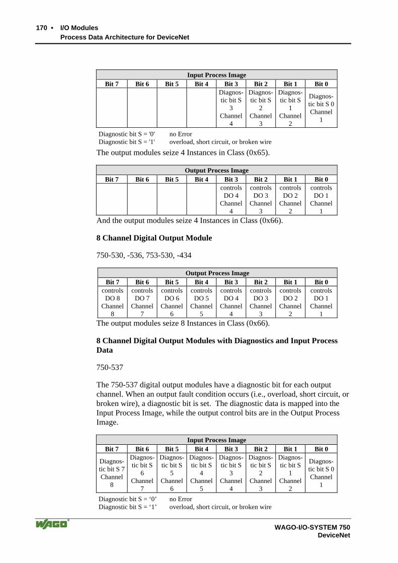
170 • I/O Modules Process Data Architecture for DeviceNet
WAGO-I/O-SYSTEM 750 DeviceNet
Input Process Image Bit 7 Bit 6 Bit 5 Bit 4 Bit 3 Bit 2 Bit 1 Bit 0
Diagnos-tic bit S
3 Channel
4
Diagnos-tic bit S
2 Channel
3
Diagnos-tic bit S
1 Channel
2
Diagnos-tic bit S 0Channel
1
Diagnostic bit S = '0' no Error Diagnostic bit S = '1' overload, short circuit, or broken wire
The output modules seize 4 Instances in Class (0x65).
Output Process Image Bit 7 Bit 6 Bit 5 Bit 4 Bit 3 Bit 2 Bit 1 Bit 0
controlsDO 4
Channel 4
controlsDO 3
Channel 3
controls DO 2
Channel 2
controlsDO 1
Channel 1
And the output modules seize 4 Instances in Class (0x66).
8 Channel Digital Output Module
750-530, -536, 753-530, -434
Output Process Image Bit 7 Bit 6 Bit 5 Bit 4 Bit 3 Bit 2 Bit 1 Bit 0
controls DO 8
Channel 8
controls DO 7
Channel 7
controlsDO 6
Channel 6
controlsDO 5
Channel 5
controlsDO 4
Channel 4
controlsDO 3
Channel 3
controls DO 2
Channel 2
controlsDO 1
Channel 1
The output modules seize 8 Instances in Class (0x66).
8 Channel Digital Output Modules with Diagnostics and Input Process Data
750-537
The 750-537 digital output modules have a diagnostic bit for each output channel. When an output fault condition occurs (i.e., overload, short circuit, or broken wire), a diagnostic bit is set. The diagnostic data is mapped into the Input Process Image, while the output control bits are in the Output Process Image.
Input Process Image Bit 7 Bit 6 Bit 5 Bit 4 Bit 3 Bit 2 Bit 1 Bit 0
Diagnos-tic bit S 7 Channel
8
Diagnos-tic bit S
6 Channel
7
Diagnos-tic bit S
5 Channel
6
Diagnos-tic bit S
4 Channel
5
Diagnos-tic bit S
3 Channel
4
Diagnos-tic bit S
2 Channel
3
Diagnos-tic bit S
1 Channel
2
Diagnos-tic bit S 0Channel
1
Diagnostic bit S = ‘0’ no Error Diagnostic bit S = ‘1’ overload, short circuit, or broken wire

I/O Modules • 171 Process Data Architecture for DeviceNet
WAGO-I/O-SYSTEM 750 DeviceNet
The output modules seize 8 Instances in Class (0x65).
Output Process Image Bit 7 Bit 6 Bit 5 Bit 4 Bit 3 Bit 2 Bit 1 Bit 0
controls DO 8
Channel 8
controlsDO 7
Channel 7
controlsDO 6
Channel 6
controlsDO 5
Channel 5
controlsDO 4
Channel 4
controls DO 3
Channel 3
controls DO 2
Channel 2
controlsDO 1
Channel 1
And the output modules seize 8 Instances in Class (0x66).
5.2.3 Analog Input Modules
The hardware of an analog input module has 16 bits of measured analog data per channel and 8 bits of control/status. However, the DeviceNet cou-pler/controller does not have access to the 8 control/status bits. Therefore, the DeviceNet coupler/controller can only access the 16 bits of analog input data per channel mapped in Intel format in the Input Process Image. When digital input modules are also present in the node, the analog input data is always mapped into the Input Process Image in front of the digital data. Each input channel seizes one Instance in the Analog Input Point Object (Class 0x67).
1 Channel Analog Input Module
750-491, (and all variations)
Input Process Image Instance Byte Destination Remark
D0 n
D1 Measured Value UD
D2 n+1
D3 Measured Value Uref
The input modules represent 2x2 bytes and seize 2 Instances in Class (0x67).

172 • I/O Modules Process Data Architecture for DeviceNet
WAGO-I/O-SYSTEM 750 DeviceNet
2 Channel Analog Input Modules
750-452, -454, -456, -461, -462, -465, -466, -467, -469, -472, -474, -475, -476, -477, -478, -479, -480, -481, -483, -485, -492, (and all variations), 753-452, -454, -456, -461, -465, -466, -467, -469, -472, -474, -475, -476, -477, -478, -479, -483, -492, (and all variations)
Input Process Image Instance Byte Destination Remark
D0 n
D1 Measured Value Channel 1
D2 n+1
D3 Measured Value Channel 2
The input modules represent 2x2 bytes and seize 2 Instances in Class (0x67).
4 Channel Analog Input Modules
750-453, -455, -457, -459, -460, -468, (and all variations), 753-453, -455, -457, -459
Input Process Image Instance Byte Destination Remark
D0 n
D1 Measured Value Channel 1
D2 n+1
D3 Measured Value Channel 2
D4 n+2
D5 Measured Value Channel 3
D6 n+3
D7 Measured Value Channel 4
The input modules represent 4x2 bytes and seize 4 Instances in Class (0x67).

I/O Modules • 173 Process Data Architecture for DeviceNet
WAGO-I/O-SYSTEM 750 DeviceNet
5.2.4 Analog Output Modules
The hardware of an analog output module has 16 bits of measured analog data per channel and 8 bits of control/status. However, the DeviceNet cou-pler/controller does not have access to the 8 control/status bits. Therefore, the DeviceNet coupler/controller can only access the 16 bits of analog output data per channel mapped in Intel format in the Output Process Image.
When digital output modules are also present in the node, the analog output data is always mapped into the Output Process Image in front of the digital data.
Each output channel seizes one Instance in the Analog Output Point Object (Class 0x68).
2 Channel Analog Output Modules
750-550, -552, -554, -556, -560, -585, (and all variations), 753-550, -552, -554, -556
Output Process Image Instance Byte Destination Remark
D0 n
D1 Output Value Channel 1
D2 n+1
D3 Output Value Channel 2
The output modules represent 2x2 bytes and seize 2 Instances in Class (0x68).
4 Channel Analog Output Modules
750-553, -555, -557, -559, 753-553, -555, -557, -559
Output Process Image Instance Byte Destination Remark
D0 n
D1 Output Value Channel 1
D2 n+1
D3 Output Value Channel 2
D4 n+2
D5 Output Value Channel 3
D6 n+3
D7 Output Value Channel 4
The output modules represent 4x2 bytes and seize 4 Instances in Class (0x68).

174 • I/O Modules Process Data Architecture for DeviceNet
WAGO-I/O-SYSTEM 750 DeviceNet
5.2.5 Specialty Modules
WAGO has a host of Specialty I/O modules that perform various functions. With individual modules beside the data bytes also the control/status byte is mapped in the process image. The control/status byte is required for the bi-directional data exchange of the module with the higher-ranking control sys-tem. The control byte is transmitted from the control system to the module and the status byte from the module to the control system.
This allows, for example, setting of a counter with the control byte or display-ing of overshooting or undershooting of the range with the status byte.
Further information For detailed information about the structure of a particular module’s con-trol/status byte, please refer to that module’s manual. Manuals for each module can be found on the Internet under: http://www.wago.com.
The Specialty Modules represent as analog modules. For this, the process input data of the Specialty Modules seize one Instance per channel in the Analog Input Point Object (Class 0x67) and the process output data seize one Instance seize one Instance in the Analog Input Point Object (Class 0x67) per channel in the Analog Output Point Object (Class 0x68).
Counter Modules
750-404, (and all variations except of /000-005), 753-404, (and variation /000-003)
The above Counter Modules have a total of 5 bytes of user data in both the In-put and Output Process Image (4 bytes of counter data and 1 byte of con-trol/status). The counter value is supplied as 32 bits. The following tables il-lustrate the Input and Output Process Image, which has a total of 6 bytes mapped into each image.
Input Process Image Instance Byte Destination Remark
S Status byte
- not used
D0
D1
D2
n
D3
Counter Value
The specialty modules represent 1x6 bytes input data and seize 1 Instance in Class (0x67).
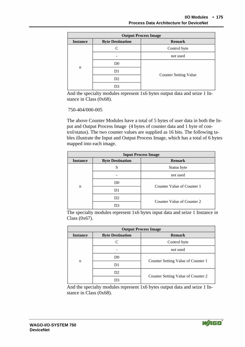
I/O Modules • 175 Process Data Architecture for DeviceNet
WAGO-I/O-SYSTEM 750 DeviceNet
Output Process Image Instance Byte Destination Remark
C Control byte
- not used
D0
D1
D2
n
D3
Counter Setting Value
And the specialty modules represent 1x6 bytes output data and seize 1 In-stance in Class (0x68).
750-404/000-005
The above Counter Modules have a total of 5 bytes of user data in both the In-put and Output Process Image (4 bytes of counter data and 1 byte of con-trol/status). The two counter values are supplied as 16 bits. The following ta-bles illustrate the Input and Output Process Image, which has a total of 6 bytes mapped into each image.
Input Process Image Instance Byte Destination Remark
S Status byte
- not used
D0
D1 Counter Value of Counter 1
D2
n
D3 Counter Value of Counter 2
The specialty modules represent 1x6 bytes input data and seize 1 Instance in Class (0x67).
Output Process Image Instance Byte Destination Remark
C Control byte
- not used
D0
D1 Counter Setting Value of Counter 1
D2
n
D3 Counter Setting Value of Counter 2
And the specialty modules represent 1x6 bytes output data and seize 1 In-stance in Class (0x68).
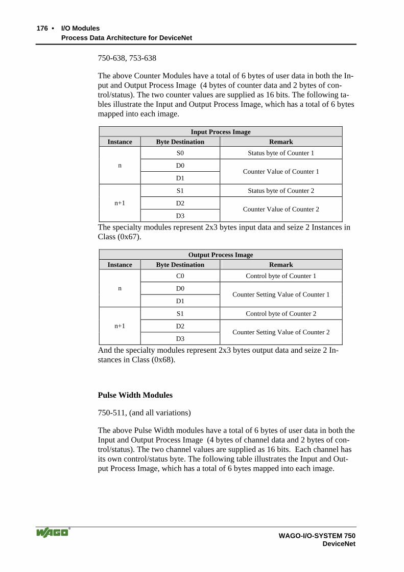
176 • I/O Modules Process Data Architecture for DeviceNet
WAGO-I/O-SYSTEM 750 DeviceNet
750-638, 753-638
The above Counter Modules have a total of 6 bytes of user data in both the In-put and Output Process Image (4 bytes of counter data and 2 bytes of con-trol/status). The two counter values are supplied as 16 bits. The following ta-bles illustrate the Input and Output Process Image, which has a total of 6 bytes mapped into each image.
Input Process Image Instance Byte Destination Remark
S0 Status byte of Counter 1
D0 n
D1 Counter Value of Counter 1
S1 Status byte of Counter 2
D2 n+1
D3 Counter Value of Counter 2
The specialty modules represent 2x3 bytes input data and seize 2 Instances in Class (0x67).
Output Process Image Instance Byte Destination Remark
C0 Control byte of Counter 1
D0 n
D1 Counter Setting Value of Counter 1
S1 Control byte of Counter 2
D2 n+1
D3 Counter Setting Value of Counter 2
And the specialty modules represent 2x3 bytes output data and seize 2 In-stances in Class (0x68).
Pulse Width Modules
750-511, (and all variations)
The above Pulse Width modules have a total of 6 bytes of user data in both the Input and Output Process Image (4 bytes of channel data and 2 bytes of con-trol/status). The two channel values are supplied as 16 bits. Each channel has its own control/status byte. The following table illustrates the Input and Out-put Process Image, which has a total of 6 bytes mapped into each image.

I/O Modules • 177 Process Data Architecture for DeviceNet
WAGO-I/O-SYSTEM 750 DeviceNet
Input and Output Process Image Instance Byte Destination Remark
C0/S0 Control/Status byte of Channel 1
D0 n
D1 Data Value of Channel 1
C1/S1 Control/Status byte of Channel 2
D2 n+1
D3 Data Value of Channel 2
The specialty modules represent 2x3 bytes input and output data and seize 2 Instances in Class (0x67) and 2 Instances in Class (0x68).
Serial Interface Modules with alternative Data Format
750-650, (and the variations /000-002, -004, -006, -009, -010, -011, -012, -013) 750-651, (and the variations /000-002, -003) 750-653, (and the variations /000-002, -007)
Note: With the freely parametrizable variations /003 000 of the serial interface modules, the desired operation mode can be set. Dependent on it, the process image of these modules is then the same, as from the appropriate variation.
The above Serial Interface Modules with alternative data format have a total of 4 bytes of user data in both the Input and Output Process Image (3 bytes of serial data and 1 byte of control/status). The following table illustrates the In-put and Output Process Image, which have a total of 4 bytes mapped into each image.
Input and Output Process Image Instance Byte Destination Remark
C/S Control/Status byte n
D0
D1 n+1
D2
Data bytes
The specialty modules represent 2x2 bytes input and output data and seize 2 Instances in Class (0x67) and 2 Instances in Class (0x68).
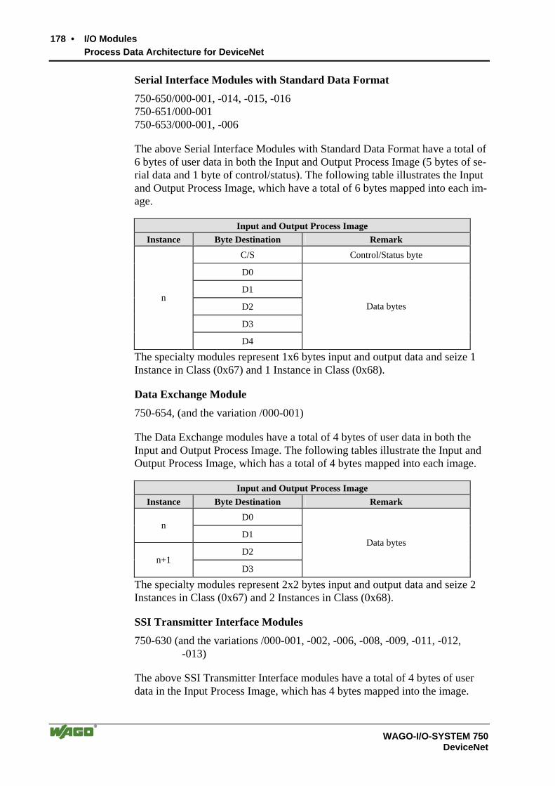
178 • I/O Modules Process Data Architecture for DeviceNet
WAGO-I/O-SYSTEM 750 DeviceNet
Serial Interface Modules with Standard Data Format
750-650/000-001, -014, -015, -016 750-651/000-001 750-653/000-001, -006
The above Serial Interface Modules with Standard Data Format have a total of 6 bytes of user data in both the Input and Output Process Image (5 bytes of se-rial data and 1 byte of control/status). The following table illustrates the Input and Output Process Image, which have a total of 6 bytes mapped into each im-age.
Input and Output Process Image Instance Byte Destination Remark
C/S Control/Status byte
D0
D1
D2
D3
n
D4
Data bytes
The specialty modules represent 1x6 bytes input and output data and seize 1 Instance in Class (0x67) and 1 Instance in Class (0x68).
Data Exchange Module
750-654, (and the variation /000-001)
The Data Exchange modules have a total of 4 bytes of user data in both the Input and Output Process Image. The following tables illustrate the Input and Output Process Image, which has a total of 4 bytes mapped into each image.
Input and Output Process Image Instance Byte Destination Remark
D0 n
D1
D2 n+1
D3
Data bytes
The specialty modules represent 2x2 bytes input and output data and seize 2 Instances in Class (0x67) and 2 Instances in Class (0x68).
SSI Transmitter Interface Modules
750-630 (and the variations /000-001, -002, -006, -008, -009, -011, -012, -013)
The above SSI Transmitter Interface modules have a total of 4 bytes of user data in the Input Process Image, which has 4 bytes mapped into the image.

I/O Modules • 179 Process Data Architecture for DeviceNet
WAGO-I/O-SYSTEM 750 DeviceNet
Input Process Image Instance Byte Destination Remark
D0 n
D1
D2 n+1
D3
Data bytes
The specialty modules represent 2x2 bytes input data and seize 2 Instances in Class (0x67).
750-630/000-004, -005, -007
The above SSI Transmitter Interface modules with status have a total of 5 bytes of user data in the Input Process Image, which has 6 bytes mapped into the image.
Input Process Image Instance Byte Destination Remark
S Status byte
- not used
D0
D1
D2
n
D3
Data bytes
The specialty modules represent 1x6 bytes input data and seize 1 Instance in Class (0x67).
Incremental Encoder Interface Modules
750-631
The above Incremental Encoder Interface modules have 5 bytes of input data and 3 bytes of output data. The following tables illustrate the Input and Output Process Image, which have 6 bytes into each image.
Input Process Image Instance Byte Destination Remark
S Status byte
D0
D1 Counter word
- not used
D2
n
D3 Latch word
The specialty modules represent 1x6 bytes input data and seize 1 Instance in Class (0x67).
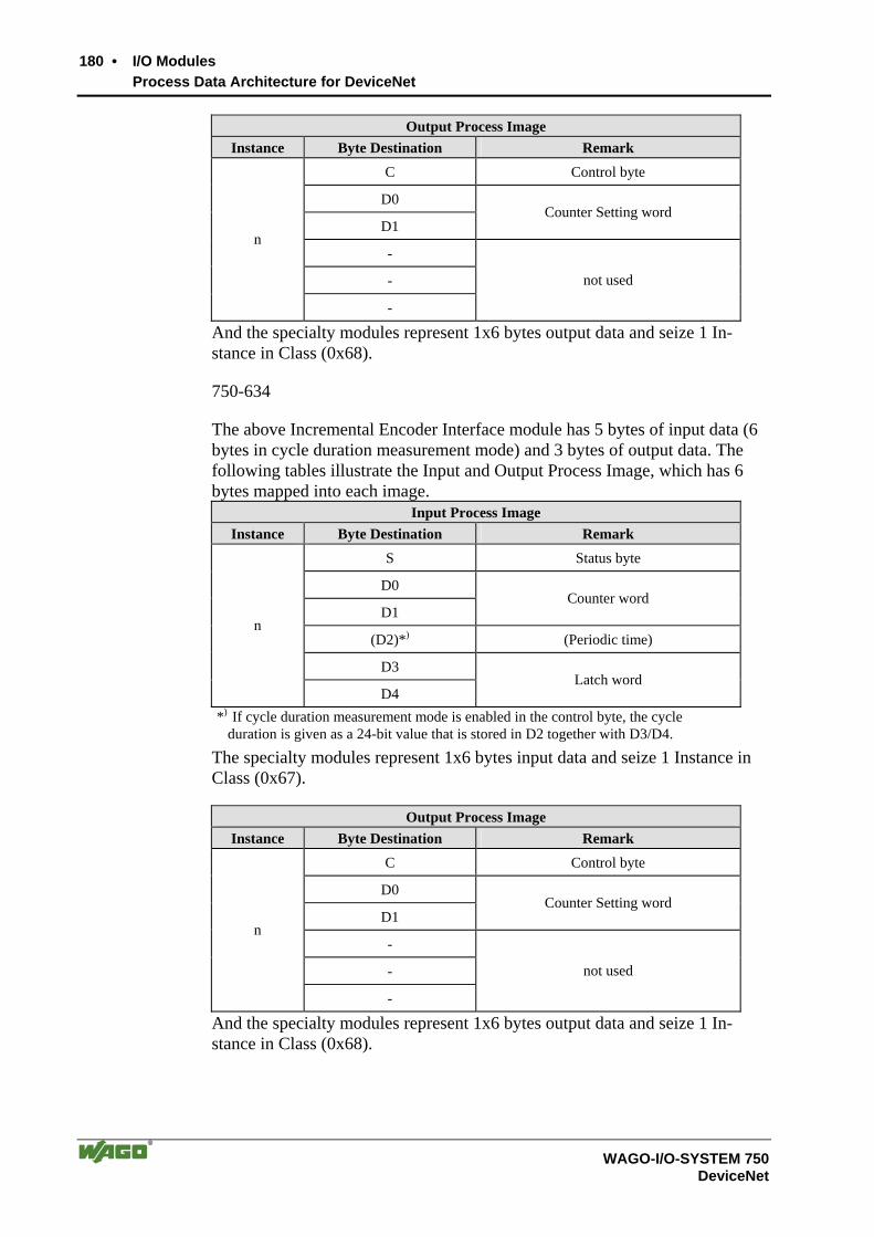
180 • I/O Modules Process Data Architecture for DeviceNet
WAGO-I/O-SYSTEM 750 DeviceNet
Output Process Image Instance Byte Destination Remark
C Control byte
D0
D1 Counter Setting word
-
-
n
-
not used
And the specialty modules represent 1x6 bytes output data and seize 1 In-stance in Class (0x68).
750-634
The above Incremental Encoder Interface module has 5 bytes of input data (6 bytes in cycle duration measurement mode) and 3 bytes of output data. The following tables illustrate the Input and Output Process Image, which has 6 bytes mapped into each image.
Input Process Image Instance Byte Destination Remark
S Status byte
D0
D1 Counter word
(D2)*) (Periodic time)
D3
n
D4 Latch word
*) If cycle duration measurement mode is enabled in the control byte, the cycle duration is given as a 24-bit value that is stored in D2 together with D3/D4.
The specialty modules represent 1x6 bytes input data and seize 1 Instance in Class (0x67).
Output Process Image Instance Byte Destination Remark
C Control byte
D0
D1 Counter Setting word
-
-
n
-
not used
And the specialty modules represent 1x6 bytes output data and seize 1 In-stance in Class (0x68).

I/O Modules • 181 Process Data Architecture for DeviceNet
WAGO-I/O-SYSTEM 750 DeviceNet
750-637
The above Incremental Encoder Interface Module has a total of 6 bytes of user data in both the Input and Output Process Image (4 bytes of encoder data and 2 bytes of control/status). The following table illustrates the Input and Output Process Image, which have 6 bytes mapped into each image.
Input and Output Process Image Instance Byte Destination Remark
C0/S0 Control/Status byte of Channel 1
D0 n
D1 Data Value of Channel 1
C1/S1 Control/Status byte of Channel 2
D2 n+1
D3 Data Value of Channel 2
The specialty modules represent 2x3 bytes input and output data and seize 2 Instances in Class (0x67) and 2 Instances in Class (0x68).
750-635, 753-635
The above Digital Pulse Interface module has a total of 4 bytes of user data in both the Input and Output Process Image (3 bytes of module data and 1 byte of control/status). The following table illustrates the Input and Output Process Image, which have 4 bytes mapped into each image.
Input and Output Process Image Instance Byte Destination Remark
C0/S0 Control/Status byte
D0
D1 n
D2
Data bytes
The specialty modules represent 1x4 bytes input and output data and seize 1 Instance in Class (0x67) and 1 Instance in Class (0x68).
RTC Module
750-640
The above RTC module has a total of 6 bytes of user data in both the Input and Output Process Image (4 bytes of module data and 1 byte of control/status and 1 byte ID for command). The following table illustrates the Input and Output Process Image, which have 6 bytes mapped into each image.

182 • I/O Modules Process Data Architecture for DeviceNet
WAGO-I/O-SYSTEM 750 DeviceNet
Input and Output Process Image Instance Byte Destination Remark
C/S Control/Status byte
ID Command byte
D0
D1
D2
n
D3
Data bytes
The specialty modules represent 1x6 bytes input data and seize 1 Instance in Class (0x67).and seize 1 Instance in Class (0x68).
DALI/DSI Master Module
750-641
The DALI/DSI Master module has a total of 6 bytes of user data in both the Input and Output Process Image (5 bytes of module data and 1 byte of con-trol/status). The following tables illustrate the Input and Output Process Im-age, which have 6 bytes mapped into each image.
Input Process Image Instance Byte Destination Remark
S Status byte
D0 DALI response
D1 DALI address
D2 Message 3
D3 Message 2
n
D4 Message 1
The specialty modules represent 1x6 bytes input data and seize 1 Instance in Class (0x67).
Output Process Image Instance Byte Destination Remark
C Control byte
D0 DALI command, DSI dimming value
D1 DALI address
D2 Parameter 2
D3 Parameter 1
n
D4 Command-Extension
And the specialty modules represent 1x6 bytes output data and seize 1 Instance in Class (0x68).
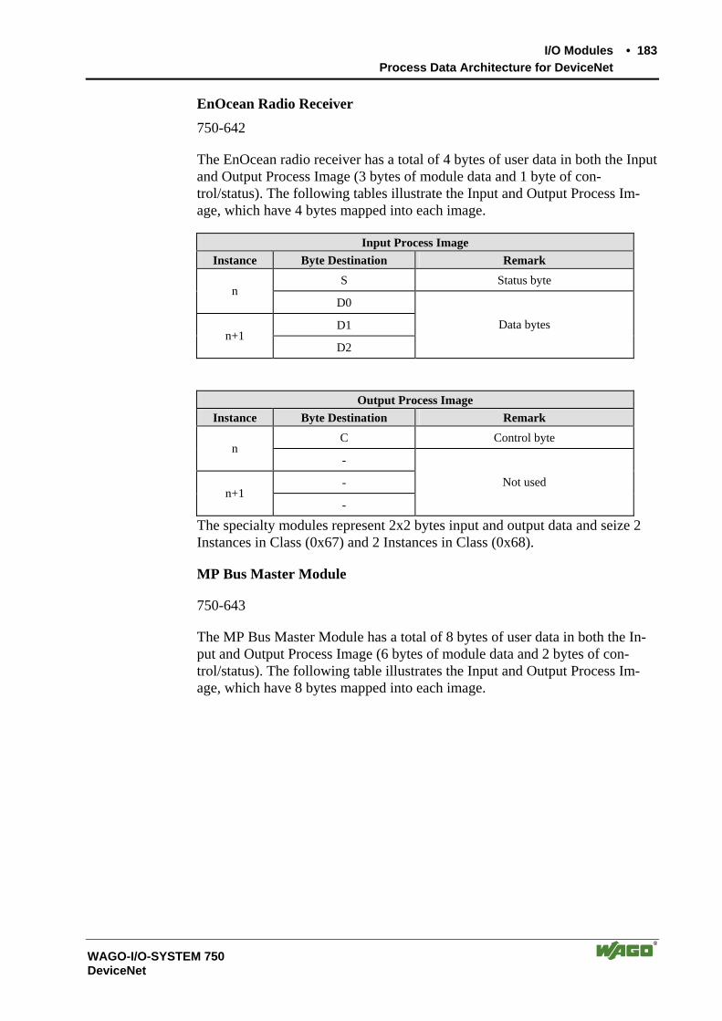
I/O Modules • 183 Process Data Architecture for DeviceNet
WAGO-I/O-SYSTEM 750 DeviceNet
EnOcean Radio Receiver
750-642
The EnOcean radio receiver has a total of 4 bytes of user data in both the Input and Output Process Image (3 bytes of module data and 1 byte of con-trol/status). The following tables illustrate the Input and Output Process Im-age, which have 4 bytes mapped into each image.
Input Process Image Instance Byte Destination Remark
S Status byte n
D0
D1 n+1
D2
Data bytes
Output Process Image Instance Byte Destination Remark
C Control byte n
-
- n+1
-
Not used
The specialty modules represent 2x2 bytes input and output data and seize 2 Instances in Class (0x67) and 2 Instances in Class (0x68).
MP Bus Master Module
750-643
The MP Bus Master Module has a total of 8 bytes of user data in both the In-put and Output Process Image (6 bytes of module data and 2 bytes of con-trol/status). The following table illustrates the Input and Output Process Im-age, which have 8 bytes mapped into each image.

184 • I/O Modules Process Data Architecture for DeviceNet
WAGO-I/O-SYSTEM 750 DeviceNet
Input and Output Process Image Instance Byte Destination Remark
C0/S0 Control/Status byte
C1/S1 extended Control/Status byte
D0
D1
D2
D3
D4
n
D5
Data bytes
The specialty modules represent 1x8 bytes input and output data and seize 1 Instance in Class (0x67) and 1 Instance in Class (0x68).
Vibration Velocity/Bearing Condition Monitoring VIB I/O
750-645
The Vibration Velocity/Bearing Condition Monitoring VIB I/O has a total of 12 bytes of user data in both the Input and Output Process Image (8 bytes of module data and 4 bytes of control/status). The following table illustrates the Input and Output Process Image, which have 12 bytes mapped into each im-age.
Input and Output Process Image Instance Byte Destination Remark
C0/S0 Control/Status byte (log. Channel 1, Sensor input 1)
D0 n
D1 Data bytes
(log. Channel 1, Sensor input 1)
C1/S1 Control/Status byte (log. Channel 2, Sensor input 2)
D2 n+1
D3 Data bytes
(log. Channel 2, Sensor input 2)
C2/S2 Control/Status byte (log. Channel 3, Sensor input 1)
D4 n+2
D5 Data bytes
(log. Channel 3, Sensor input 1)
C3/S3 Control/Status byte (log. Channel 4, Sensor input 2)
D6 n+3
D7 Data bytes
(log. Channel 4, Sensor input 2)
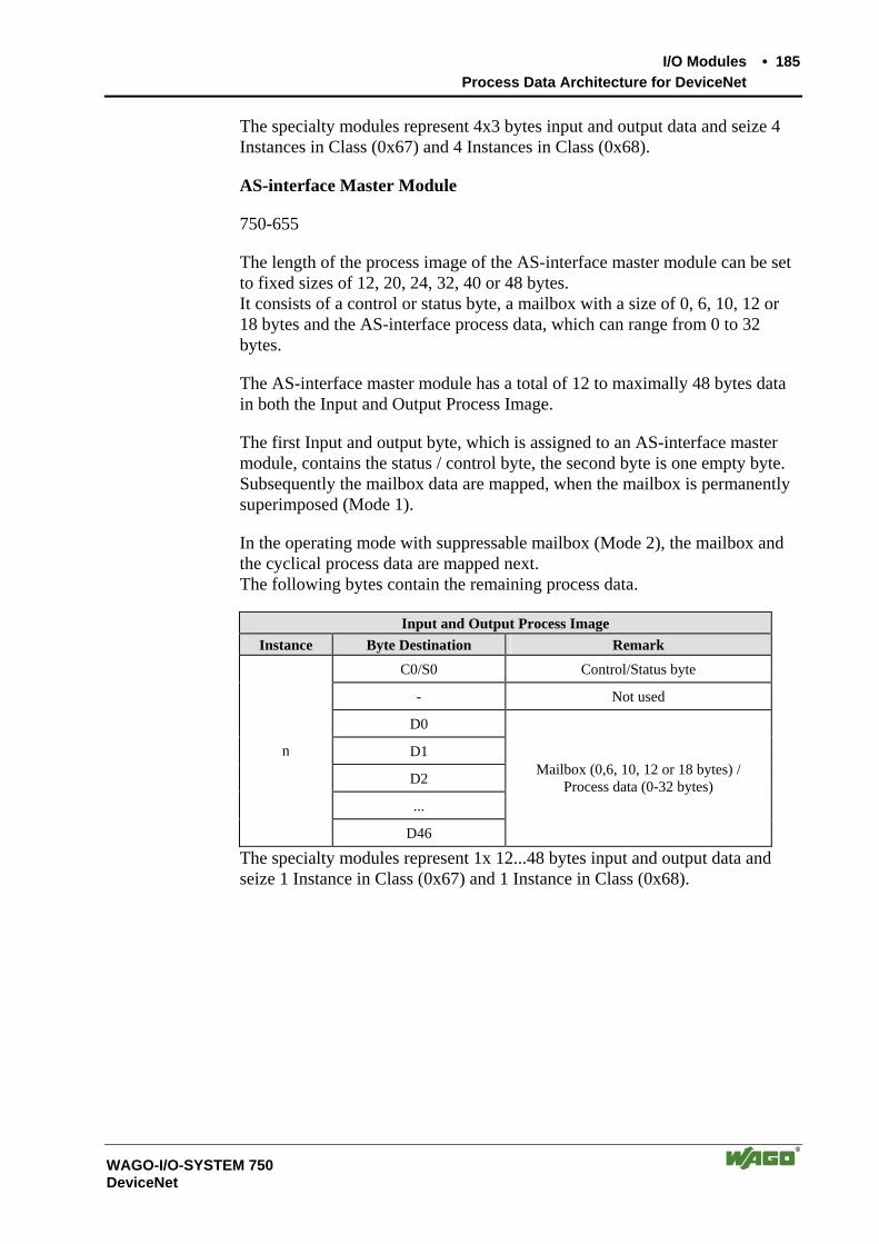
I/O Modules • 185 Process Data Architecture for DeviceNet
WAGO-I/O-SYSTEM 750 DeviceNet
The specialty modules represent 4x3 bytes input and output data and seize 4 Instances in Class (0x67) and 4 Instances in Class (0x68).
AS-interface Master Module
750-655
The length of the process image of the AS-interface master module can be set to fixed sizes of 12, 20, 24, 32, 40 or 48 bytes. It consists of a control or status byte, a mailbox with a size of 0, 6, 10, 12 or 18 bytes and the AS-interface process data, which can range from 0 to 32 bytes.
The AS-interface master module has a total of 12 to maximally 48 bytes data in both the Input and Output Process Image.
The first Input and output byte, which is assigned to an AS-interface master module, contains the status / control byte, the second byte is one empty byte. Subsequently the mailbox data are mapped, when the mailbox is permanently superimposed (Mode 1).
In the operating mode with suppressable mailbox (Mode 2), the mailbox and the cyclical process data are mapped next. The following bytes contain the remaining process data.
Input and Output Process Image Instance Byte Destination Remark
C0/S0 Control/Status byte
- Not used
D0
D1
D2
...
n
D46
Mailbox (0,6, 10, 12 or 18 bytes) / Process data (0-32 bytes)
The specialty modules represent 1x 12...48 bytes input and output data and seize 1 Instance in Class (0x67) and 1 Instance in Class (0x68).
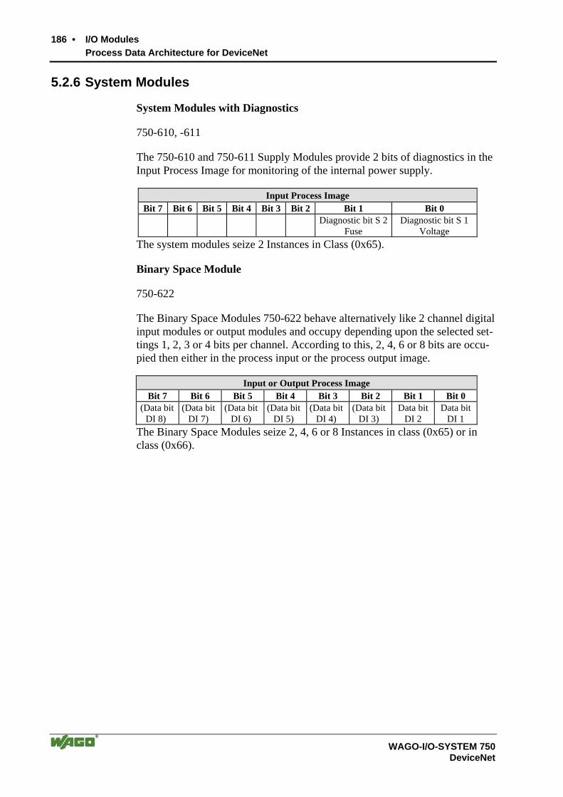
186 • I/O Modules Process Data Architecture for DeviceNet
WAGO-I/O-SYSTEM 750 DeviceNet
5.2.6 System Modules
System Modules with Diagnostics
750-610, -611
The 750-610 and 750-611 Supply Modules provide 2 bits of diagnostics in the Input Process Image for monitoring of the internal power supply.
Input Process Image Bit 7 Bit 6 Bit 5 Bit 4 Bit 3 Bit 2 Bit 1 Bit 0
Diagnostic bit S 2Fuse
Diagnostic bit S 1Voltage
The system modules seize 2 Instances in Class (0x65).
Binary Space Module
750-622
The Binary Space Modules 750-622 behave alternatively like 2 channel digital input modules or output modules and occupy depending upon the selected set-tings 1, 2, 3 or 4 bits per channel. According to this, 2, 4, 6 or 8 bits are occu-pied then either in the process input or the process output image.
Input or Output Process Image Bit 7 Bit 6 Bit 5 Bit 4 Bit 3 Bit 2 Bit 1 Bit 0
(Data bitDI 8)
(Data bit DI 7)
(Data bitDI 6)
(Data bitDI 5)
(Data bitDI 4)
(Data bitDI 3)
Data bit DI 2
Data bitDI 1
The Binary Space Modules seize 2, 4, 6 or 8 Instances in class (0x65) or in class (0x66).
Use in Hazardous Environments • 187 Foreword
WAGO-I/O-SYSTEM 750 DeviceNet
6 Use in Hazardous Environments 6.1 Foreword
Today’s development shows that many chemical and petrochemical compa-nies have production plants, production, and process automation machines in operation which use gas-air, vapor-air and dust-air mixtures which can be ex-plosive. For this reason, the electrical components used in such plants and sys-tems must not pose a risk of explosion resulting in injury to persons or damage to property. This is backed by law, directives or regulations on a national and international scale. WAGO-I/O-SYSTEM 750 (electrical components) is de-signed for use in zone 2 explosive environments. The following basic explo-sion protection related terms have been defined.
6.2 Protective measures Primarily, explosion protection describes how to prevent the formation of an explosive atmosphere. For instance by avoiding the use of combustible liq-uids, reducing the concentration levels, ventilation measures, to name but a few. But there are a large number of applications, which do not allow the im-plementation of primary protection measures. In such cases, the secondary ex-plosion protection comes into play. Following is a detailed description of such secondary measures.
6.3 Classification meeting CENELEC and IEC The specifications outlined here are valid for use in Europe and are based on the following standards: EN50... of CENELEC (European Committee for Electrotechnical Standardization). On an international scale, these are re-flected by the IEC 60079-... standards of the IEC (International Electrotechni-cal Commission).
6.3.1 Divisions
Explosive environments are areas in which the atmosphere can potentially be-come explosive. The term explosive means a special mixture of ignitable sub-stances existing in the form of air-borne gases, fumes, mist or dust under at-mospheric conditions which, when heated beyond a tolerable temperature or subjected to an electric arc or sparks, can produce explosions. Explosive zones have been created to describe the concentrations level of an explosive atmos-phere. This division, based on the probability of an explosion occurring, is of great importance both for technical safety and feasibility reasons. Knowing that the demands placed on electrical components permanently employed in an explosive environment have to be much more stringent than those placed on electrical components that are only rarely and, if at all, for short periods, sub-ject to a dangerous explosive environment.
188 • Use in Hazardous Environments Classification meeting CENELEC and IEC
WAGO-I/O-SYSTEM 750 DeviceNet
Explosive areas resulting from gases, fumes or mist:
Zone 0 areas are subject to an explosive atmosphere (> 1000 h /year) continuously or for extended periods.
Zone 1 areas can expect the occasional occurrence of an explosive atmos-phere (> 10 h ≤ 1000 h /year).
Zone 2 areas can expect the rare or short-term occurrence of an explosive at-mosphere (> 0 h ≤ 10 h /year).
Explosive areas subject to air-borne dust:
Zone 20 areas are subject to an explosive atmosphere (> 1000 h /year) continuously or for extended periods.
Zone 21 areas can expect the occasional occurrence of an explosive atmos-phere (> 10 h ≤ 1000 h /year).
Zone 22 areas can expect the rare or short-term occurrence of an explosive atmosphere (> 0 h ≤ 10 h /year).
6.3.2 Explosion protection group
In addition, the electrical components for explosive areas are subdivided into two groups:
Group I: Group I includes electrical components for use in fire-damp endangered mine structures.
Group II: Group II includes electrical components for use in all other explosive environments. This group is further subdivided by pertinent combustible gases in the environment. Subdivision IIA, IIB and IIC takes into account that differ-ent materials/substances/gases have various ignition energy characteristic values. For this reason the three sub-groups are assigned representative types of gases:
IIA – Propane IIB – Ethylene IIC – Hydrogen
Minimal ignition energy of representative types of gases
Explosion group I IIA IIB IIC
Gases Methane Propane Ethylene Hydrogen
Ignition energy (µJ) 280 250 82 16
Use in Hazardous Environments • 189 Classification meeting CENELEC and IEC
WAGO-I/O-SYSTEM 750 DeviceNet
Hydrogen being commonly encountered in chemical plants, frequently the ex-plosion group IIC is requested for maximum safety.
6.3.3 Unit categories
Moreover, the areas of use (zones) and the conditions of use (explosion groups) are subdivided into categories for the electrical operating means:
Unit categories
Explosion group
Area of use
M1 I Fire-damp protection
M2 I Fire-damp protection
1G II Zone 0 Explosive environment by gas, fumes or mist
2G II Zone 1 Explosive environment by gas, fumes or mist
3G II Zone 2 Explosive environment by gas, fumes or mist
1D II Zone 20 Explosive environment by dust
2D II Zone 21 Explosive environment by dust
3D II Zone 22 Explosive environment by dust
6.3.4 Temperature classes
The maximum surface temperature for electrical components of explosion pro-tection group I is 150 °C (danger due to coal dust deposits) or 450 °C (if there is no danger of coal dust deposit).
In line with the maximum surface temperature for all ignition protection types, the electrical components are subdivided into temperature classes, as far as electrical components of explosion protection group II are concerned. Here the temperatures refer to a surrounding temperature of 40 °C for operation and testing of the electrical components. The lowest ignition temperature of the existing explosive atmosphere must be higher than the maximum surface tem-perature.
Temperature classes Maximum surface temperature
Ignition temperature of the combustible materials
T1 450 °C > 450 °C
T2 300 °C > 300 °C to 450 °C
T3 200 °C > 200 °C to 300 °C
T4 135 °C > 135 °C to 200 °C
T5 100 °C >100 °C to 135 °C
T6 85°C > 85 °C to 100 °C
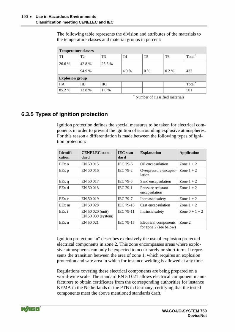
190 • Use in Hazardous Environments Classification meeting CENELEC and IEC
WAGO-I/O-SYSTEM 750 DeviceNet
The following table represents the division and attributes of the materials to the temperature classes and material groups in percent:
Temperature classes T1 T2 T3 T4 T5 T6 Total*
26.6 % 42.8 % 25.5 %
94.9 % 4.9 % 0 % 0.2 % 432
Explosion group IIA IIB IIC Total* 85.2 % 13.8 % 1.0 % 501
* Number of classified materials
6.3.5 Types of ignition protection
Ignition protection defines the special measures to be taken for electrical com-ponents in order to prevent the ignition of surrounding explosive atmospheres. For this reason a differentiation is made between the following types of igni-tion protection:
Identifi-cation
CENELEC stan-dard
IEC stan-dard
Explanation Application
EEx o EN 50 015 IEC 79-6 Oil encapsulation Zone 1 + 2 EEx p EN 50 016 IEC 79-2 Overpressure encapsu-
lation Zone 1 + 2
EEx q EN 50 017 IEC 79-5 Sand encapsulation Zone 1 + 2 EEx d EN 50 018 IEC 79-1 Pressure resistant
encapsulation Zone 1 + 2
EEx e EN 50 019 IEC 79-7 Increased safety Zone 1 + 2 EEx m EN 50 028 IEC 79-18 Cast encapsulation Zone 1 + 2 EEx i EN 50 020 (unit)
EN 50 039 (system) IEC 79-11 Intrinsic safety Zone 0 + 1 + 2
EEx n EN 50 021 IEC 79-15 Electrical components for zone 2 (see below)
Zone 2
Ignition protection “n" describes exclusively the use of explosion protected electrical components in zone 2. This zone encompasses areas where explo-sive atmospheres can only be expected to occur rarely or short-term. It repre-sents the transition between the area of zone 1, which requires an explosion protection and safe area in which for instance welding is allowed at any time.
Regulations covering these electrical components are being prepared on a world-wide scale. The standard EN 50 021 allows electrical component manu-facturers to obtain certificates from the corresponding authorities for instance KEMA in the Netherlands or the PTB in Germany, certifying that the tested components meet the above mentioned standards draft.
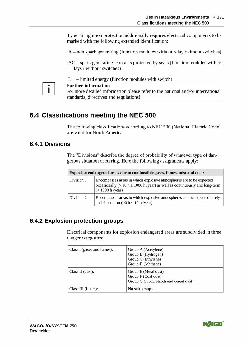
Use in Hazardous Environments • 191 Classifications meeting the NEC 500
WAGO-I/O-SYSTEM 750 DeviceNet
Type “n” ignition protection additionally requires electrical components to be marked with the following extended identification:
A – non spark generating (function modules without relay /without switches)
AC – spark generating, contacts protected by seals (function modules with re-lays / without switches)
L – limited energy (function modules with switch)
Further information For more detailed information please refer to the national and/or international standards, directives and regulations!
6.4 Classifications meeting the NEC 500 The following classifications according to NEC 500 (National Electric Code) are valid for North America.
6.4.1 Divisions
The "Divisions" describe the degree of probability of whatever type of dan-gerous situation occurring. Here the following assignments apply:
Explosion endangered areas due to combustible gases, fumes, mist and dust:
Division 1 Encompasses areas in which explosive atmospheres are to be expected occasionally (> 10 h ≤ 1000 h /year) as well as continuously and long-term (> 1000 h /year).
Division 2 Encompasses areas in which explosive atmospheres can be expected rarely and short-term (>0 h ≤ 10 h /year).
6.4.2 Explosion protection groups
Electrical components for explosion endangered areas are subdivided in three danger categories:
Class I (gases and fumes): Group A (Acetylene) Group B (Hydrogen) Group C (Ethylene) Group D (Methane)
Class II (dust): Group E (Metal dust) Group F (Coal dust) Group G (Flour, starch and cereal dust)
Class III (fibers): No sub-groups
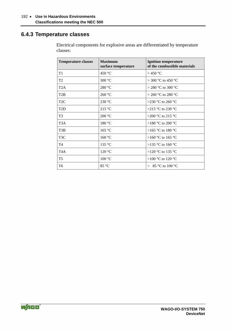
192 • Use in Hazardous Environments Classifications meeting the NEC 500
WAGO-I/O-SYSTEM 750 DeviceNet
6.4.3 Temperature classes
Electrical components for explosive areas are differentiated by temperature classes:
Temperature classes Maximum surface temperature
Ignition temperature of the combustible materials
T1 450 °C > 450 °C
T2 300 °C > 300 °C to 450 °C
T2A 280 °C > 280 °C to 300 °C
T2B 260 °C > 260 °C to 280 °C
T2C 230 °C >230 °C to 260 °C
T2D 215 °C >215 °C to 230 °C
T3 200 °C >200 °C to 215 °C
T3A 180 °C >180 °C to 200 °C
T3B 165 °C >165 °C to 180 °C
T3C 160 °C >160 °C to 165 °C
T4 135 °C >135 °C to 160 °C
T4A 120 °C >120 °C to 135 °C
T5 100 °C >100 °C to 120 °C
T6 85 °C > 85 °C to 100 °C
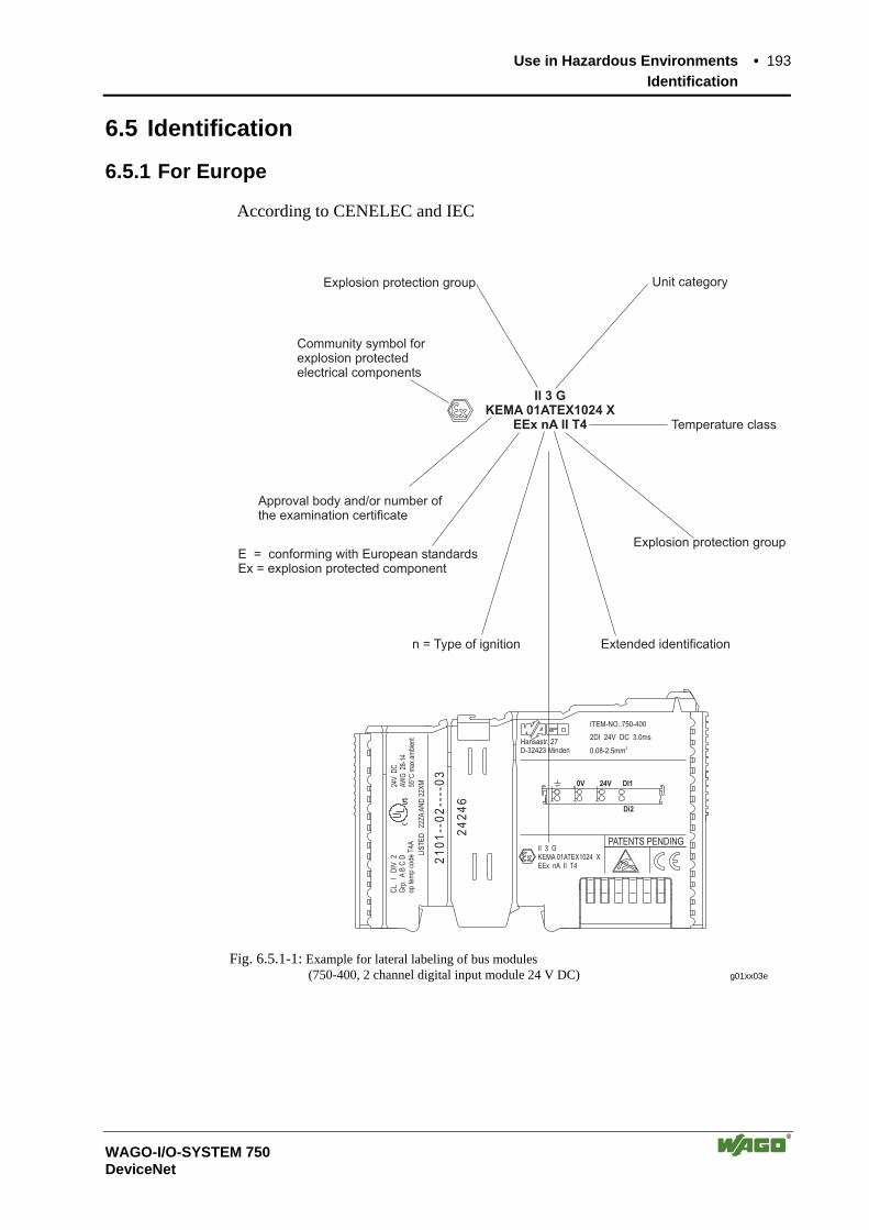
Use in Hazardous Environments • 193 Identification
WAGO-I/O-SYSTEM 750 DeviceNet
6.5 Identification
6.5.1 For Europe
According to CENELEC and IEC
Hansastr. 27D-32423 Minden
ITEM-NO.:750-400
2DI 24V DC 3.0ms
0.08-2.5mm2
0V 24V DI1
Di2
PATENTS PENDINGII 3 GKEMA 01ATEX1024 XEEx nA II T4
CL
ID
IV2
Grp
.A
BC
Dop
tem
pco
deT
4A
24V
DC
AW
G28
-14
55°C
max
ambi
ent
LIS
TE
D22
ZA
AN
D22
XM
24
24
6
21
01
- -0
2- -
- -0
3
II 3 GKEMA 01ATEX1024 X
EEx nA II T4
Explosion protection group Unit category
Community symbol forexplosion protectedelectrical components
Approval body and/or number ofthe examination certificate
E = conforming with European standardsEx = explosion protected component
n = Type of ignition Extended identification
Explosion protection group
Temperature class
Fig. 6.5.1-1: Example for lateral labeling of bus modules (750-400, 2 channel digital input module 24 V DC) g01xx03e

194 • Use in Hazardous Environments Identification
WAGO-I/O-SYSTEM 750 DeviceNet
6.5.2 For America
According to NEC 500
Hansastr. 27D-32423 Minden
ITEM-NO.:750-400
2DI 24V DC 3.0ms
0.08-2.5mm2
0V 24V DI1
Di2
PATENTS PENDINGII 3 GKEMA 01ATEX1024 XEEx nA II T4
CL
ID
IV2
Grp
.A
BC
Dop
tem
pco
deT
4A
24V
DC
AW
G28
-14
55°C
max
ambi
ent
24
24
6
41
00
--0
2--
--0
3
LIS
TE
D22
ZA
AN
D22
XM
CL I DIV 2Grp. ABCD
optemp code T4A
Explosion group(gas group)
Explosion protection group(condition of use category)
Area of application (zone)
Temperature class
Fig. 6.5.2-1: Example for lateral labeling of bus modules (750-400, 2 channel digital input module 24 V DC) g01xx04e

Use in Hazardous Environments • 195 Installation regulations
WAGO-I/O-SYSTEM 750 DeviceNet
6.6 Installation regulations In the Federal Republic of Germany, various national regulations for the in-stallation in explosive areas must be taken into consideration. The basis being the ElexV complemented by the installation regulation DIN VDE 0165/2.91. The following are excerpts from additional VDE regulations:
DIN VDE 0100 Installation in power plants with rated voltages up to 1000 V
DIN VDE 0101 Installation in power plants with rated voltages above 1 kV
DIN VDE 0800 Installation and operation in telecommunication plants including information processing equipment
DIN VDE 0185 lightning protection systems
The USA and Canada have their own regulations. The following are excerpts from these regulations:
NFPA 70 National Electrical Code Art. 500 Hazardous Locations
ANSI/ISA-RP 12.6-1987
Recommended Practice
C22.1 Canadian Electrical Code
196 • Use in Hazardous Environments Installation regulations
WAGO-I/O-SYSTEM 750 DeviceNet
Danger When using the WAGO-I/O SYSTEM 750 (electrical operation) with Ex ap-proval, the following points are mandatory:
The fieldbus independent I/O System Modules Type 750-xxx are to be in-stalled in enclosures that provide for the degree of ingress protection of at least IP54. For use in the presence of combustible dust, the above mentioned modulesare to be installed in enclosures that provide for the degree of ingress pro-tection of at least IP64.
The fieldbus independent I/O system may only be installed in hazardous areas(Europe: Group II, Zone 2 or America: Class I, Division 2, Group A, B, C,D) or in non-hazardous areas!
Installation, connection, addition, removal or replacement of modules, field-bus connectors or fuses may only take place when the system supply and the field supply are switched off, or when the area is known to be non-hazardous.
Ensure that only approved modules of the electrical operating type will be used. The Substitution or Replacement of modules can jeopardize the suit-ability of the system in hazardous environments!
Operation of intrinsically safe EEx i modules with direct connection to sen-sors/actuators in hazardous areas of Zone 0 + 1 and Division 1 type re-quires the use of a 24 V DC Power Supply EEx i module!
DIP switches and potentiometers are only to be adjusted when the area is know to be non-hazardous.
Further Information Proof of certification is available on request. Also take note of the informa-tion given on the module technical information sheet.
Glossary • 197
WAGO-I/O-SYSTEM 750 DeviceNet
7 Glossary Bit Smallest information unit. Its value can either be 1 or
0.
Bitrate Number of bits transmitted within a time unit.
Bootstrap Operating mode of the fieldbus Coupler / Controllers. Device expects a firmware upload.
Bus A structure used to transmit data. There are two types, serial and parallel. A serial bus transmits data bit by bit, whereas a parallel bus transmits many bits at one time.
Byte Binary Yoked Transfer Element. A byte generally contains 8 bits.
Data bus see Bus.
Fieldbus System for serial information transmission between devices of automation technology in the process-related field area.
Hardware Electronic, electrical and mechanic components of a module/subassembly.
Operating system Software which links the application programs to the hardware.
Segment Typically, a network is divided up into different physical network segments by way of routers or re-peaters.
Server Device providing services within a client/server sys-tem. The service is requested by the Client.
Subnet A portion of a network that shares the same network address as the other portions. These subnets are dis-tinguished through the subnet mask.

198 • Literature List
WAGO-I/O-SYSTEM 750 DeviceNet
8 Literature List
Controller-Area-Network Grundlagen, Protokolle, Bausteine, Anwendungen Konrad Etschberger 2., völlig überarbeitete Auflage 2000 Carl Hanser Verlag München Wien ISBN 3-4446-19431-2
Further information on web pages:
The ODVA provides further documentation on DeviceNet. www.odva.org
CAN in Automation (CiA) provides further documentation on CAN. can-cia.de

Index • 199
WAGO-I/O-SYSTEM 750 DeviceNet
9 Index
C carrier rail · 16, 19 contacts
data- · 20 power- · 27
Controller · 8 Coupler · 8 Cycle time · 72
D data contacts · 20
E Electrical isolation · 43, 67
F Fieldbus interface · 72 Fieldbus node · 111 Fieldbus start · 72 Flag · 72 Flags · 82 Flash memory · 72
H Hardware reset · 69
I I/O modules
Address range · 81 IEC 61131-3 · 105 Internal bus · 65, 72, 103
L Light diodes · 44, 68 locking disc · 18 Loop · 72
O Operating mode
RUN · 69 STOP · 69
Operating mode switch · 69, 72, 78, 86
P PFC cycle · 78 PLC cycle · 72 PLC program · 72 Power contacts · 21, 27
not carried out · 28 power jumper contacts · 44 Process image · 47, 62, 72, 105
R RAM · 72 RUN · 72
S Start-up · 72 STOP · 72 Subnet · 156
T Times · 72
U unlocking lug · 18
V Variables · 69
W WAGO-I/O-PRO 32 · 70, 85, 89

200 • Index
WAGO-I/O-SYSTEM 750 DeviceNet
WAGO Kontakttechnik GmbH & Co. KG
Postfach 2880 • D-32385 Minden Hansastraße 27 • D-32423 Minden Phone: 05 71/8 87 – 0 Fax: 05 71/8 87 – 1 69 E-Mail: [email protected] Web: http://www.wago.com