MANUAL AS-I 3.0 PROFIBUS ATEWAY WITH...
156
AS-I 3.0 PROFIBUS GATEWAY WITH INTEGR. SAFETY MONITOR FACTORY AUTOMATION MANUAL
Transcript of MANUAL AS-I 3.0 PROFIBUS ATEWAY WITH...
AS-I 3.0 PROFIBUS GATEWAY WITH INTEGR. SAFETY MONITOR
FACTORY AUTOMATION
MANUAL

With regard to the supply of products, the current issue of the following document is applicable: The General Terms of Delivery for Products and Services of the Electrical Industry, published by the Central Association of the Electrical Industry (Zentralverband Elektrotechnik und Elektroindustrie (ZVEI) e.V.) in its most recent version as well as the supplementary clause: "Expanded reservation of proprietorship".
AS-i 3.0 PROFIBUS Gateway with integr. Safety Monitor
AS-i 3.0 PROFIBUS Gateway with integr. Safety MonitorTable of contents
2.5.
2013
Table of contents
Table of contents
1 Introduction...........................................................................................9
2 Declaration of conformity ..................................................................102.1 Declaration of conformity.............................................................................. 10
3 Safety ...................................................................................................113.1 Symbols relevant to safety............................................................................ 11
3.2 General notes on safety ................................................................................ 11
3.3 Disposal .......................................................................................................... 11
4 General ................................................................................................124.1 Product information....................................................................................... 124.1.1 AS-i 3.0 PROFIBUS Gateway with integr. Safety Monitor ..........................................124.1.2 AS-i 3.0 PROFIBUS Gateway, PROFIsafe for 2 AS-i circuits .....................................13
4.2 New Generation of AS-i Gateways with ethernet diagnostics interface ... 13
4.3 Brief description............................................................................................. 14
5 Spezifications - AS-i/PROFIBUS Gateways......................................165.1 Technical data ................................................................................................ 16
5.2 Safety-relevant characteristic data............................................................... 175.2.1 Overview of parameter for determining the failure rates...........................................18
5.3 Reaction times................................................................................................ 195.3.1 Sensor -> local relay output..........................................................................................195.3.2 Sensor -> local electronic output .................................................................................195.3.3 Sensor -> AS-i relay output...........................................................................................205.3.4 Sensor -> AS-i electronic output ..................................................................................205.3.5 System reaction times – example calculations ..........................................................21
5.4 Scope of delivery ........................................................................................... 24
6 Spezifications - AS-i/PROFIsafe Gateways ......................................256.1 Technical data ................................................................................................ 25
6.2 Safety-relevant characteristic data............................................................... 26
6.3 Reaction times................................................................................................ 276.3.1 Ethernet (PROFIsafe) -> local relay output..................................................................276.3.2 Ethernet (PROFIsafe) -> local electronic output .........................................................276.3.3 Ethernet (PROFIsafe) -> AS-i relay output...................................................................286.3.4 Ethernet (PROFIsafe) -> AS-i electronic output ..........................................................28
3
2.5
.201
3
AS-i 3.0 PROFIBUS Gateway with integr. Safety MonitorTable of contents
7 Installation ...........................................................................................297.1 Dimensions .................................................................................................... 29
7.2 Connections ................................................................................................... 30
7.3 Installing in the control cabinet.................................................................... 31
7.4 Removing ....................................................................................................... 31
7.5 Electrical Connection .................................................................................... 32
7.6 Commissioning.............................................................................................. 327.6.1 Switching to advanced display mode..........................................................................327.6.2 Setting the PROFIBUS-DP address 14.........................................................................327.6.3 Setting the PROFIsafe address 17 ...............................................................................337.6.4 Connecting AS-i Slaves ................................................................................................347.6.5 Quick setup ....................................................................................................................357.6.6 Error tracing ...................................................................................................................367.6.6.1 Faulty slaves.................................................................................................................367.6.6.2 Error display (last error) ................................................................................................36
7.7 Addressing ..................................................................................................... 377.7.1 Assigning address 15 to slave currently at address 2...............................................37
7.8 Local parameter setting of safe AS-i/Gateways and Monitors .................. 38
7.9 Replacing a defective safety-configured AS-i slave................................... 40
7.10 Replacing the chip card ................................................................................ 40
7.11 Replacing a defective device........................................................................ 427.11.1 Teaching the group manager after replacing a device ..............................................44
7.12 Replacing the monitor................................................................................... 45
7.13 Safe configuration using ASIMON 3 G2 ..................................................... 48
8 Maintenance ........................................................................................508.1 Checking for safe turn-off............................................................................. 50
9 Electrical connection..........................................................................519.1 Overview of terminals, indicators and operating elements....................... 519.1.1 VBG-PB-K30-D-S............................................................................................................519.1.2 VBG-PB-K30-DMD-S16, VBG-PB-K30-D-S16, VBG-PBS-K30-DMD ...........................529.1.3 VBG-PB-K30-DMD-S16-EV ............................................................................................53
9.2 AS-i bus connection ...................................................................................... 54
9.3 Information about the device types ............................................................. 54
9.4 AS-i and power supply terminal assignments ............................................ 549.4.1 Electrical connection VBG-PB-K30-D-S16, VBG-PB-K30-D-S ..................................559.4.2 Electrical connection VBG-PB-K30-DMD-S16, VBG-PBS-K30-DMD .........................569.4.3 Electrical connection VBG-PB-K30-DMD-S16-EV.......................................................57
9.5 Diagnostics interface .................................................................................... 589.5.1 VBG-PB-K30-DMD-S16, VBG-PB-K30-D-S16, VBG-PB-K30-D-S, VBG-PBS-K30-DMD
589.5.2 VBG-PB-K30-DMD-S16-EV ............................................................................................589.5.3 SafeLink over ethernet (VBG-PB-K30-DMD-S16-EV)..................................................59
4
AS-i 3.0 PROFIBUS Gateway with integr. Safety MonitorTable of contents
2.5.
2013
9.6 Chip card......................................................................................................... 59
9.7 PROFIBUS interface....................................................................................... 609.7.1 Terminating resistors on the PROFIBUS network.....................................................60
9.8 Release circuits.............................................................................................. 619.8.1 Wiring overview of safety unit
VBG-PB-K30-DMD-S16, VBG-PB-K30-D-S16, VBG-PBS-K30-DMD, VBG-PB-K30-DMD-S16-EV61
9.8.2 Wiring overview of safety unit VBG-PB-K30-D-S........................................................62
9.9 Indicators and operating elements............................................................... 639.9.1 LED indicators – master................................................................................................639.9.2 LED indicators - safety unit
VBG-PB-K30-DMD-S16, VBG-PB-K30-D-S16, VBG-PBS-K30-DMD, VBG-PB-K30-DMD-S16-EV64
9.9.3 LED indicators – safety unit VBG-PB-K30-D-S ...........................................................649.9.4 Buttons ...........................................................................................................................65
10 Function and startup of the Safety Monitor .....................................6610.1 Powering up the device ................................................................................. 66
10.2 Configuration of the safety functions .......................................................... 6610.2.1 Description of configuration using ASIMON 3 G2 software ......................................6710.2.2 Description of configuration using chip card with master configuration ................6810.2.3 Configuration using a chip card with complete configuration..................................68
10.3 Safety-relevant documentation of the application...................................... 69
10.4 Diagnostic data .............................................................................................. 6910.4.1 Diagnostics of release circuits 1-4 via the binary data .............................................7010.4.2 Switch-off history ..........................................................................................................70
10.5 Password protection...................................................................................... 7010.5.1 Procedure for configuring and teaching code sequences ........................................7110.5.2 Function of the ESC/Service key..................................................................................72
10.6 Safe coupling slaves on the AS-i circuits.................................................... 72
10.7 Chip card......................................................................................................... 7210.7.1 Unsafe data ....................................................................................................................7210.7.1.1 Card unformatted..........................................................................................................7210.7.1.2 Data not compatible ......................................................................................................7310.7.1.3 Card empty ...................................................................................................................7310.7.1.4 Data compatible ............................................................................................................7310.7.1.5 Data in the device and on the chip card identical .........................................................7310.7.1.6 Data in the device and on the chip card not identical ...................................................7410.7.2 Safe data.........................................................................................................................7410.7.2.1 Data incompatible .........................................................................................................7410.7.2.2 Data compatible ............................................................................................................7510.7.2.3 Complete configuration .................................................................................................7510.7.2.4 Data on the chip card and in the device are identical ...................................................7510.7.2.5 Data not identical ..........................................................................................................7610.7.2.6 Operating the chip card from the menu ........................................................................7610.7.3 Working with multiple memory banks .........................................................................76
5
2.5
.201
3
AS-i 3.0 PROFIBUS Gateway with integr. Safety MonitorTable of contents
11 Operation in advanced display mode ...............................................78
12 Advanced Diagnostics for AS-i Masters...........................................7912.1 List of corrupted AS-i Slaves (LCS) ............................................................. 79
12.2 Protocol analysis: Counters for corrupted data telegrams ....................... 79
12.3 Offline Phase for Configuration Errors........................................................ 80
12.4 Functions of the AS-i Fault Detector ........................................................... 8012.4.1 Duplicate address detection.........................................................................................8012.4.2 Earth/Ground Fault Detector ........................................................................................8112.4.3 Noise Detector ...............................................................................................................8112.4.4 Over-voltage Detector ...................................................................................................81
12.5 Functions of the new generation of AS-i Gateways ................................... 8212.5.1 C-programmable Gateways ..........................................................................................8212.5.2 Interchangeable memory card......................................................................................8212.5.3 Earth fault monitor.........................................................................................................8212.5.4 Current can be read directly on the unit......................................................................8312.5.5 Self-resetting fuses .......................................................................................................8412.5.6 AS-i Power24V capable .................................................................................................8412.5.7 Ethernet diagnostics interface with web server .........................................................8512.5.8 Transitionless operating mode changes.....................................................................85
13 PROFIBUS DP .....................................................................................8613.1 DP telegrams.................................................................................................. 8613.1.1 Diagnostics ....................................................................................................................8613.1.1.1 Parameters ...................................................................................................................9113.1.2 Configuration DP/V0 (cyclic data) ................................................................................9113.1.2.1 Options .........................................................................................................................9113.1.3 I/O Data ...........................................................................................................................9513.1.3.1 Process data.................................................................................................................9513.1.3.2 EC-Flags and AS-i detector ..........................................................................................9613.1.3.3 Power Control (current limit) .........................................................................................9713.1.3.4 AS-i 16 bit data .............................................................................................................9813.1.3.5 Command interface ......................................................................................................9913.1.3.6 Safety Control/Status....................................................................................................9913.1.3.7 Fieldbus bit .................................................................................................................10213.1.3.8 Diagnostics in the cyclic channel (10 Byte SafeLink.Diag.) ........................................103
13.2 DP/V1 ............................................................................................................ 104
13.3 PROFIBUS .................................................................................................... 104
14 Configuration with Windows Software ASIMON 3 G2 ...................105
15 SafeLink .............................................................................................10615.1 General introduction .................................................................................. 106
15.2 Configuration ............................................................................................... 10715.2.1 Configuration using ASIMON .....................................................................................108
15.3 Diagnostics ................................................................................................. 109
6
AS-i 3.0 PROFIBUS Gateway with integr. Safety MonitorTable of contents
2.5.
2013
16 System startup using AS-i Control Tools.......................................11116.1 Windows software AS-i Control Tools ....................................................... 111
16.2 PROFIBUS DP Master Simulator ................................................................ 114
17 Status indication, faults and fault elimination ...............................11517.1 Spontaneous display of faults from the safety unit.................................. 115
17.2 Replacing a defective safety-configured AS-i slave ................................. 116
17.3 Replacing a defective AS-i Safety Monitor ................................................ 117
17.4 Forget the password? What do I do now?................................................. 117
18 Glossary ............................................................................................119
19 Appendix: Example for startup on a Siemens S7..........................12419.1 Hardware configuration............................................................................... 12419.1.1 Electrical connection for AS-i.....................................................................................12419.1.2 Electrical connection for PROFIBUS DP ...................................................................125
19.2 SIMATIC Step 7 Configuration .................................................................... 12519.2.1 Configuration of the Hardware ...................................................................................12519.2.2 Insert AS-i/Gateway with safety monitor ...................................................................12819.2.3 AS-i 3.0 PROFIBUS Gateway with integr. Safety Monitor
configure in-/outputs ..............................................................................................13219.2.4 AS-i/Gateway with safety monitor parameters .........................................................13519.2.4.1 General DP parameters ..............................................................................................13719.2.4.2 AS-i-Parameter Slave 1/1A.........................................................................................13719.2.4.3 Hex parameterizing.....................................................................................................13919.2.5 SIMATIC Step7 blocks.................................................................................................13919.2.6 Variable table VAT_ASI_IO .........................................................................................14019.2.6.1 AS-i flags byte 0, input bits 7 - 4 .................................................................................14219.2.6.2 AS-i flags byte 0, output bits 7 - 4 ...............................................................................14219.2.7 System behavior on AS-i Config Error ......................................................................144
19.3 Device-specific parameters......................................................................... 147
20 Codes indicated by the display .......................................................150
21 Appendix: Startup on a Siemens NC control .................................15221.1 Setting in the S7 configuration ................................................................... 152
21.2 Setting in the NC control ............................................................................. 153
21.3 Setting “PROFISAFE_IN_ADDRESS“......................................................... 153
21.4 Setting “PROFISAFE_OUT_ADDRESS“..................................................... 153
21.5 Setting “PROFISAFE_IN_ASSIGN“ ............................................................ 153
21.6 Setting “PROFISAFE_OUT_ASSIGN"......................................................... 154
21.7 Setting “PROFISAFE_IN_FILTER".............................................................. 154
21.8 Setting “PROFISAFE_OUT_FILTER".......................................................... 154
7
2.5
.201
3
AS-i 3.0 PROFIBUS Gateway with integr. Safety MonitorTable of contents
22 Reference List ...................................................................................15522.1 Manual: “ASIMON 3 G2 Configuration Software“..................................... 155
22.2 Sources......................................................................................................... 155
8
AS-i 3.0 PROFIBUS Gateway with integr. Safety MonitorIntroduction
2.5.
2013
9
1. IntroductionCongratulationsYou have chosen a device manufactured by Pepperl+Fuchs. Pepperl+Fuchs de-velops, produces and distributes electronic sensors and interface modules for themarket of automation technology on a worldwide scale.Before installing this equipment and put into operation, read this manual carefully.This manual containes instructions and notes to help you through the installationand commissioning step by step. This makes sure bring such a trouble-free use ofthis product. This is for your benefit, since this:• ensures the safe operation of the device• helps you to exploit the full functionality of the device• avoids errors and related malfunctions• avoids costs by disruptions and any repairs• increases the effectiveness and efficiency of your plantKeep this manual at hand for subsequent operations on the device.After opening the packaging please check the integrity of the device and thenumber of pieces of supplied.
Symbols usedThe following symbols are used in this manual:
ContactIf you have any questions about the device, its functions, or accessories, pleasecontact us at:
Pepperl+Fuchs GmbHLilienthalstraße 20068307 MannheimTelephone: +49 621 776-4411Fax: +49 621 776-274411E-Mail: [email protected]
Information!This symbol indicates important information.
Attention!This symbol warns of a potential failure. Non-compliance may lead to interruptions ofthe device, the connected peripheral systems, or plant, potentially leading to total mal-functioning.
Warning!This symbol warns of an imminent danger. Non-compliance may lead to personal inju-ries that could be fatal or result in material damages and destruction.

2.5
.201
3
10
AS-i 3.0 PROFIBUS Gateway with integr. Safety MonitorDeclaration of conformity
2. Declaration of conformity
2.1 Declaration of conformityThis product was developed and manufactured under observance of the applica-ble European standards and guidelines.
The product manufacturer, Pepperl+Fuchs GmbH, D-68307 Mannheim, has acertified quality assurance system that conforms to ISO 9001.
Information!A Declaration of Conformity can be requested from the manufacturer.
AS-i 3.0 PROFIBUS Gateway with integr. Safety MonitorSafety
2.5.
2013
11
3. Safety
3.1 Symbols relevant to safety
3.2 General notes on safetyOnly instructed specialist staff may operate the device in accordance with the op-erating manual.User modification and or repair are dangerous and will void the warranty and ex-clude the manufacturer from any liability. If serious faults occur, stop using the de-vice. Secure the device against inadvertent operation. In the event of repairs, re-turn the device to your local Pepperl+Fuchs representative or sales office.The connection of the device and maintenance work when live may only be car-ried out by a qualified electrical specialist.The operating company bears responsibility for observing locally applicable safe-ty regulations.Store the not used device in the original packaging. This offers the device optimalprotection against impact and moisture.Ensure that the ambient conditions comply with regulations.
3.3 Disposal
Information!This symbol indicates important information.
Attention!This symbol warns of a potential failure. Non-compliance may lead to interruptions ofthe device, the connected peripheral systems, or plant, potentially leading to total mal-functioning.
Warning!This symbol warns of an imminent danger. Non-compliance may lead to personal inju-ries that could be fatal or result in material damages and destruction.
Information!Electronic waste is hazardous waste. Please comply with all local ordinances whendisposing this product!The device does not contain batteries that need to be removed before disposing it.
2.5
.201
3
AS-i 3.0 PROFIBUS Gateway with integr. Safety MonitorGeneral
4. General
4.1 Product informationThis system manual applies to the following Pepperl+Fuchs GmbH equipment:
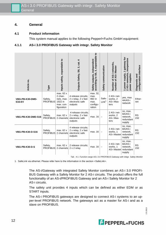
4.1.1 AS-i 3.0 PROFIBUS Gateway with integr. Safety Monitor
The AS-i/Gateway with integrated Safety Monitor combines an AS-i 3.0 PROFI-BUS Gateway with a Safety Monitor for 2 AS-i circuits. The product offers the fullfunctionality of an AS-i/PROFIBUS Gateway and an AS-i Safety Monitor for 2 AS-i circuits.The safety unit provides 4 inputs which can be defined as either EDM or asSTART inputs.The AS-i PROFIBUS gateways are designed to connect AS-i systems to an up-per-level PROFIBUS network. The gateways act as a master for AS-i and as aslave on PROFIBUS.
Art
icle
no.
Type
Inpu
ts s
afet
y, e
xpan
dabl
e to
Out
puts
Saf
ety,
SIL
3, c
at. 4
Safe
ty o
utpu
ts, i
ndep
ende
nt
acco
rdin
g to
SIL
3, e
xpan
dabl
e to
Safe
ty c
omm
unic
atio
n
Num
ber o
f AS-
i net
wor
ks,
num
ber o
f AS-
i Mas
ter
1 po
wer
sup
ply,
1 g
atew
ay fo
r 2
AS-
i net
wor
ks, i
nexp
ensi
ve
pow
er s
uppl
ies
Dia
gnos
tic a
nd
conf
igur
atio
n in
terf
ace
VBG-PB-K30-DMD-S16-EV
Safety, PROFIBUS
max. 62 x 2 chan-nels, max. 1922 in max. con-figuration
4 release circuits; 2 x relay, 2 x fast electronic safe outputs
max. 32, max. 992 in max. configu-ration
Safe-Link1
2 AS-i net-works, 2 AS-i Mas-ters
yes, max. 4A/AS-i network
Ether-net
VBG-PB-K30-DMD-S16 Safety, PROFIBUS
max. 62 x 2 channels
4 release circuits; 2 x relay, 2 x fast electronic safe outputs
max. 16 –
2 AS-i net-works, 2 AS-i Mas-ters
no, max. 8A/AS-i network, redundant supply
RS 232
VBG-PB-K30-D-S16 Safety, PROFIBUS
max. 62 x 2 channels
4 release circuits; 2 x relay, 2 x fast electronic safe outputs
max. 16 –2 AS-i net-works, 1 AS-i Master
no, max. 8A/AS-i network, redundant supply
RS 232
VBG-PB-K30-D-S Safety, PROFIBUS
max. 62 x 2 channels
2 release circuits; 2 x 2 relay max. 16 –
2 AS-i net-works, 1 AS-i Master
no, max. 8A/AS-i network, redundant supply
RS 232
Tab. 4-1. Function range AS-i 3.0 PROFIBUS Gateway with integr. Safety Monitor
1. SafeLink via ethernet. Please refer here to the information in the section <SafeLink>.
12
AS-i 3.0 PROFIBUS Gateway with integr. Safety MonitorGeneral
2.5.
2013
All AS-i functions can be used cyclically as well as acyclically via PROFIBUS DP/ V1.For the cyclical data transfer up to 32 bytes of I/O data can be transferred as bina-ry data for one AS-i network. Additionally, analog signals and all available com-mands of the new AS-i specification can be transferred via the command channelthrough PROFIBUS. On the serial PROFIBUS Master AS-i Control Tools can be used to monitor theAS-i data online via PROFIBUS DP/V1.
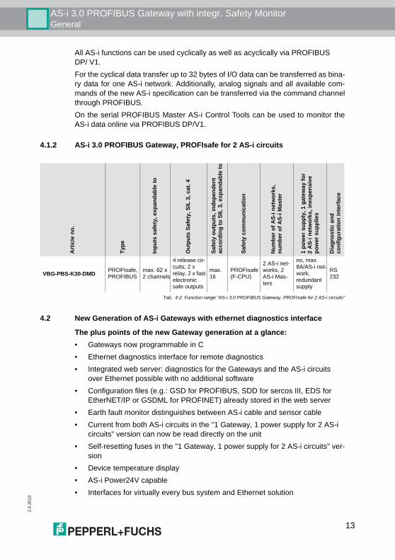
4.1.2 AS-i 3.0 PROFIBUS Gateway, PROFIsafe for 2 AS-i circuits
4.2 New Generation of AS-i Gateways with ethernet diagnostics interface
The plus points of the new Gateway generation at a glance:• Gateways now programmable in C • Ethernet diagnostics interface for remote diagnostics• Integrated web server: diagnostics for the Gateways and the AS-i circuits
over Ethernet possible with no additional software• Configuration files (e.g.: GSD for PROFIBUS, SDD for sercos III, EDS for
EtherNET/IP or GSDML for PROFINET) already stored in the web server• Earth fault monitor distinguishes between AS-i cable and sensor cable• Current from both AS-i circuits in the "1 Gateway, 1 power supply for 2 AS-i
circuits" version can now be read directly on the unit • Self-resetting fuses in the "1 Gateway, 1 power supply for 2 AS-i circuits" ver-
sion• Device temperature display• AS-i Power24V capable• Interfaces for virtually every bus system and Ethernet solution
Art
icle
no.
Type
Inpu
ts s
afet
y, e
xpan
dabl
e to
Out
puts
Saf
ety,
SIL
3, c
at. 4
Safe
ty o
utpu
ts, i
ndep
ende
nt
acco
rdin
g to
SIL
3, e
xpan
dabl
e to
Safe
ty c
omm
unic
atio
n
Num
ber o
f AS-
i net
wor
ks,
num
ber o
f AS-
i Mas
ter
1 po
wer
sup
ply,
1 g
atew
ay fo
r 2
AS-
i net
wor
ks, i
nexp
ensi
ve
pow
er s
uppl
ies
Dia
gnos
tic a
nd
conf
igur
atio
n in
terf
ace
VBG-PBS-K30-DMD PROFIsafe, PROFIBUS
max. 62 x 2 channels
4 release cir-cuits; 2 x relay, 2 x fast electronic safe outputs
max. 16
PROFIsafe (F-CPU)
2 AS-i net-works, 2 AS-i Mas-ters
no, max. 8A/AS-i net-work, redundant supply
RS 232
Tab. 4-2. Function range "AS-i 3.0 PROFIBUS Gateway, PROFIsafe for 2 AS-i circuits"
13
2.5
.201
3
AS-i 3.0 PROFIBUS Gateway with integr. Safety MonitorGeneral
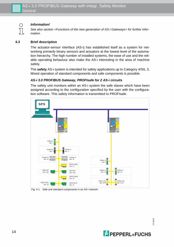
4.3 Brief descriptionThe actuator-sensor interface (AS-i) has established itself as a system for net-working primarily binary sensors and actuators at the lowest level of the automa-tion hierarchy. The high number of installed systems, the ease of use and the reli-able operating behaviour also make the AS-i interesting in the area of machinesafety.The safety AS-i system is intended for safety applications up to Category 4/SIL 3.Mixed operation of standard components and safe components is possible.
AS-i 3.0 PROFIBUS Gateway, PROFIsafe for 2 AS-i circuitsThe safety unit monitors within an AS-i system the safe slaves which have beenassigned according to the configuration specified by the user with the configura-tion software. This safety information is transmitted to PROFIsafe.
Fig. 4-1. Safe and standard components in an AS-i network
Information!See also section <Functions of the new generation of AS-i Gateways> for further infor-mation.
AS-i Safety Integrated
1.Y1
Aux
2.Y1
K1
K3
1.Y2
2.Y2
K2
K4
2.13
+
24 V
2.Y1
0 V
+
1.13
2.Y2
1.Y2
2.14
+
4.14
+
1.14
1.Y1
3.14ESCService
Mode
OKSet
+ASI 1 +ASI 2 ASI+PWR+ASI 1
AS-i Safety Integrated
1.Y1
Aux
2.Y1
K1
K3
1.Y2
2.Y2
K2
K4
2.13
+
24 V
2.Y1
0 V
+
1.13
2.Y2
1.Y2
2.14
+
4.14
+
1.14
1.Y1
3.14ESCService
Mode
OKSet
+ASI 1 +ASI 2 ASI+PWR+ASI 1
Safety In
Adr. 1
Analog In
Adr. 3
Analog In
Adr. 4
Analog In
Adr. 10
Analog In
Adr. 11
OEM Safety
Adr. 21
OEM 3O
Adr. 22AOEM 3O
Adr. 23A
OEM Safety
Adr. 24
OEM 4I/4O
Adr. 26OEM 2I/2O
Adr. 27
Safety In
Adr. 6
Safety In
Adr. 12
Safety In
Adr. 13
Safety Out
Adr. 4/7B
Safety Out
Adr. 2/7A
SPS
14
AS-i 3.0 PROFIBUS Gateway with integr. Safety MonitorGeneral
2.5.
2013
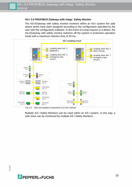
AS-i 3.0 PROFIBUS Gateway with integr. Safety MonitorThe AS-i/Gateway with safety monitor monitors within an AS-i system the safeslaves which have been assigned according to the configuration specified by theuser with the configuration software. In the event of a stop request or a defect, theAS-i/Gateway with safety monitor switches off the system in protective operationmode with a maximum reaction time of 40 ms.
Fig. 4-2. Safe and standard components in an AS-i network
Multiple AS-i Safety Monitors can be used within an AS-i system. In this way, asafe slave can be monitored by multiple AS-i Safety Monitors.
AS-i Safety Integrated
1.Y1
Aux
2.Y1
K1
K3
1.Y2
2.Y2
K2
K4
2.13
+
24 V
2.Y1
0 V
+
1.13
2.Y2
1.Y2
2.14
+
4.14
+
1.14
1.Y1
3.14ESCService
Mode
OKSet
AS-i Safety Integrated
1.Y1
Aux
2.Y1
K1
K3
1.Y2
2.Y2
K2
K4
2.13
+
24 V
2.Y1
0 V
+
1.13
2.Y2
1.Y2
2.14
+
4.14
+
1.14
1.Y1
3.14ESCService
Mode
OKSet
Safety In
Adr. 1
Analog In
Adr. 3
Analog In
Adr. 4
Analog In
Adr. 10
Analog In
Adr. 11
OEM Safety
Adr. 21
OEM 3O
Adr. 22AOEM 3O
Adr. 23A
OEM Safety
Adr. 24
OEM 4I/4O
Adr. 26OEM 2I/2O
Adr. 27
Safety In
Adr. 6
Safety In
Adr. 12
Safety In
Adr. 13
Safety Out
Adr. 4/7B
Safety Out
Adr. 2/7A
AS-i coupling circuit
coupling slave Adr. 2emergency-stop circuit 1
coupling slave Adr. 1lightgrids 1
coupling slave Adr. 7emergency-stop circuit 2
coupling slave Adr. 6silent running
15
2.5
.201
3
AS-i 3.0 PROFIBUS Gateway with integr. Safety MonitorSpezifications - AS-i/PROFIBUS Gateways
5. Spezifications - AS-i/PROFIBUS Gateways
5.1 Technical dataThe technical data are placed in the data sheet. Please view the current versionon the web page: http://www.pepperl-fuchs.com.
Attention!
The AS-I power supply for the AS-I components must have isolation per IEC 60 742and be able to handle momentary power interruptions of up to 20 ms. The power sup-ply for the 24 V supply must also have isolation per IEC 60 742 and be able to handlemomentary power interruptions of up to 20 ms. The maximum output voltage of thepower supply must also be less than 42 V in case of a fault.
16
AS-i 3.0 PROFIBUS Gateway with integr. Safety MonitorSpezifications - AS-i/PROFIBUS Gateways
2.5.
2013
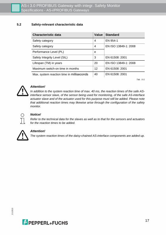
5.2 Safety-relevant characteristic data
Characteristic data Value Standard
Safety category 4 EN 954-1
Safety category 4 EN ISO 13849-1: 2008
Performance Level (PL) e
Safety Integrity Level (SIL) 3 EN 61508: 2001
Lifespan (TM) in years 20 EN ISO 13849-1: 2008
Maximum switch-on time in months 12 EN 61508: 2001
Max. system reaction time in milliseconds 40 EN 61508: 2001
Tab. 5-3.
Attention!In addition to the system reaction time of max. 40 ms, the reaction times of the safe AS-interface sensor slave, of the sensor being used for monitoring, of the safe AS-interfaceactuator slave and of the actuator used for this purpose must still be added. Please notethat additional reaction times may likewise arise through the configuration of the safetymonitor.
Notice!Refer to the technical data for the slaves as well as to that for the sensors and actuatorsfor the reaction times to be added.
Attention!The system reaction times of the daisy-chained AS-interface components are added up.
17
2.5
.201
3
AS-i 3.0 PROFIBUS Gateway with integr. Safety MonitorSpezifications - AS-i/PROFIBUS Gateways
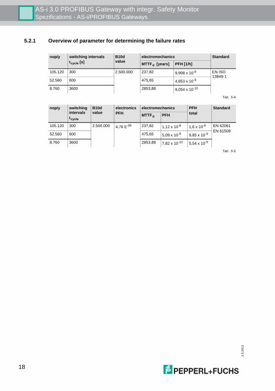
5.2.1 Overview of parameter for determining the failure rates
nop/y switching intervalstcycle [s]
B10d value
electromechanics Standard
MTTFd [years] PFH [1/h]
105.120 300 2.500.000 237,82 9,908 x 10-9 EN ISO 13849-1
52.560 600 475,65 4,853 x 10-9
8.760 3600 2853,88 9,054 x 10-10
Tab. 5-4.
nop/y switching intervalstcycle
B10d value
electronicsPFH
electromechanics PFHtotal
Standard
MTTFd PFH
105.120 300 2.500.000 4,76 E-09 237,82 1,12 x 10⁻⁸ 1,6 x 10⁻⁸ EN 62061EN 61508
52.560 600 475,65 5,09 x 10⁻⁹ 9,85 x 10⁻⁹
8.760 3600 2853,88 7,82 x 10⁻¹⁰ 5,54 x 10⁻⁹
Tab. 5-5.
18
AS-i 3.0 PROFIBUS Gateway with integr. Safety MonitorSpezifications - AS-i/PROFIBUS Gateways
2.5.
2013
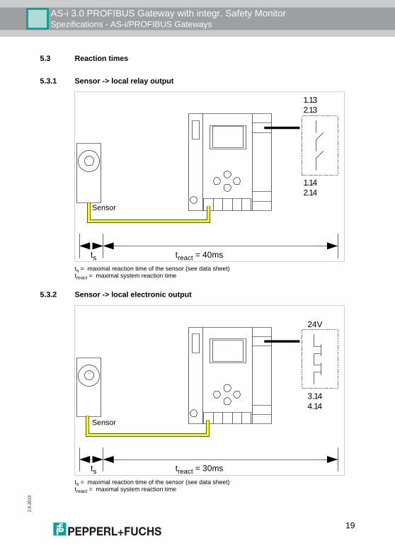
5.3 Reaction times
5.3.1 Sensor -> local relay output
ts = maximal reaction time of the sensor (see data sheet)treact = maximal system reaction time
5.3.2 Sensor -> local electronic output
ts = maximal reaction time of the sensor (see data sheet)treact = maximal system reaction time
treact = 40ms
1.13
2.13
1.14
2.14
ts
Sensor
treact = 30ms
24V
3.14
4.14
ts
Sensor
19
2.5
.201
3
AS-i 3.0 PROFIBUS Gateway with integr. Safety MonitorSpezifications - AS-i/PROFIBUS Gateways
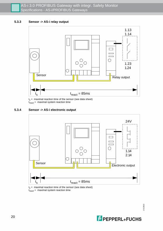
5.3.3 Sensor -> AS-i relay output
ts = maximal reaction time of the sensor (see data sheet)treact = maximal system reaction time
5.3.4 Sensor -> AS-i electronic output
ts = maximal reaction time of the sensor (see data sheet)treact = maximal system reaction time
treact = 85ms
1.13
1.14
1.23
1.24
ts
Relay outputSensor
treact = 85ms
ts
24V
1.14
2.14
Electronic outputSensor
20
AS-i 3.0 PROFIBUS Gateway with integr. Safety MonitorSpezifications - AS-i/PROFIBUS Gateways
2.5.
2013
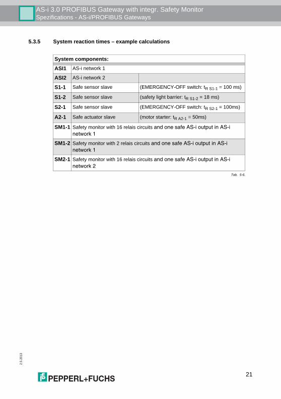
5.3.5 System reaction times – example calculations
System components:
ASI1 AS-i network 1
ASI2 AS-i network 2
S1-1 Safe sensor slave (EMERGENCY-OFF switch: tR S1-1 = 100 ms)
S1-2 Safe sensor slave (safety light barrier: tR S1-2 = 18 ms)
S2-1 Safe sensor slave (EMERGENCY-OFF switch: tR S2-1 = 100ms)
A2-1 Safe actuator slave (motor starter: tR A2-1 = 50ms)
SM1-1 Safety monitor with 16 relais circuits and one safe AS-i output in AS-i network 1
SM1-2 Safety monitor with 2 relais circuits and one safe AS-i output in AS-i network 1
SM2-1 Safety monitor with 16 relais circuits and one safe AS-i output in AS-i network 2
Tab. 5-6.
21
2.5
.201
3
AS-i 3.0 PROFIBUS Gateway with integr. Safety MonitorSpezifications - AS-i/PROFIBUS Gateways
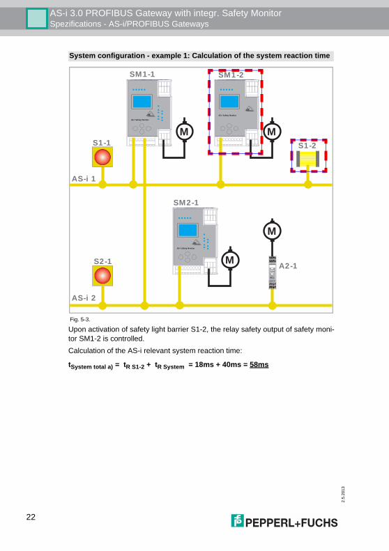
Upon activation of safety light barrier S1-2, the relay safety output of safety moni-tor SM1-2 is controlled.Calculation of the AS-i relevant system reaction time:
tSystem total a) = tR S1-2 + tR System = 18ms + 40ms = 58ms
System configuration - example 1: Calculation of the system reaction time
Fig. 5-3.
AS-i 1
AS-i 2
S1-2S1-1
A2-1
SM1-1 SM1-2
S2-1
AS-i Safety Monitor
AS-i Safety Monitor
M
AS-i Safety Monitor
SM2-1
M
M
I –
I1
1.13
ASI+
I +
I 2
1.14
ASI–
I +
1.Y1
1.23
nc
I +
1.Y2
1.24
nc
I1
Pwr
Faul
t
Out
1.Y1
1.Y2
I 2
Prg
Run
Alarm
Prg
M
22
AS-i 3.0 PROFIBUS Gateway with integr. Safety MonitorSpezifications - AS-i/PROFIBUS Gateways
2.5.
2013
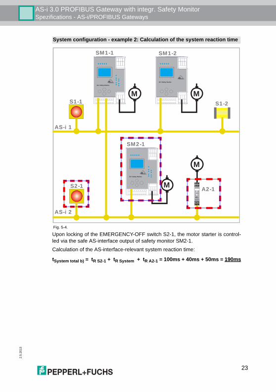
Upon locking of the EMERGENCY-OFF switch S2-1, the motor starter is control-led via the safe AS-interface output of safety monitor SM2-1.Calculation of the AS-interface-relevant system reaction time:
tSystem total b) = tR S2-1 + tR System + tR A2-1 = 100ms + 40ms + 50ms = 190ms
System configuration - example 2: Calculation of the system reaction time
Fig. 5-4.
AS-i 1
AS-i 2
S1-2S1-1
A2-1
SM1-1 SM1-2
S2-1
AS-i Safety Monitor
AS-i Safety Monitor
M
AS-i Safety Monitor
SM2-1
M
M
I –
I1
1.13
ASI+
I +
I 2
1.14
ASI–
I +
1.Y1
1.23
nc
I +
1.Y2
1.24
nc
I1
Pwr
Faul
t
Out
1.Y1
1.Y2
I 2
Prg
Run
Alarm
Prg
M
23
2.5
.201
3
AS-i 3.0 PROFIBUS Gateway with integr. Safety MonitorSpezifications - AS-i/PROFIBUS Gateways
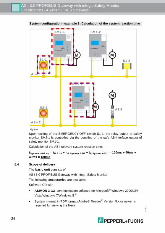
Upon locking of the EMERGENCY-OFF switch S1-1, the relay output of safetymonitor SM2-1 is controlled via the coupling of the safe AS-interface output ofsafety monitor SM1-1. Calculation of the AS-i relevant system reaction time:
tSystem total c) = tR S1-1 + tR System ASI1 + tR System ASI2 = 100ms + 40ms + 40ms = 180ms
5.4 Scope of deliveryThe basic unit consists of:AS-i 3.0 PROFIBUS Gateway with integr. Safety Monitor.The following accessories are available:Software CD with
• ASIMON 3 G2 communication software for Microsoft® Windows 2000/XP/Vista/Windows 7/Windows 8 ®
• System manual in PDF format (Adobe® Reader® Version 5.x or newer is required for viewing the files)
System configuration - example 3: Calculation of the system reaction time
Fig. 5-5.
AS-i 1
AS-i 2
S1-2S1-1
A2-1
SM1-1 SM1-2
S2-1
AS-i Safety Monitor
AS-i Safety Monitor
M
AS-i Safety Monitor
SM2-1
M
M
I –
I1
1.13
ASI+
I +
I 2
1.14
ASI–
I +
1.Y1
1.23
nc
I +
1.Y2
1.24
nc
I1
Pwr
Faul
t
Out
1.Y1
1.Y2
I 2
Prg
Run
Alarm
Prg
M
24
AS-i 3.0 PROFIBUS Gateway with integr. Safety MonitorSpezifications - AS-i/PROFIsafe Gateways
2.5.
2013
6. Spezifications - AS-i/PROFIsafe Gateways
6.1 Technical dataThe technical data are placed in the data sheet. Please view the current versionon the web page: http://www.pepperl-fuchs.com.
Attention!
The AS-I power supply for the AS-I components must have isolation per IEC 60 742and be able to handle momentary power interruptions of up to 20 ms. The power sup-ply for the 24 V supply must also have isolation per IEC 60 742 and be able to handlemomentary power interruptions of up to 20 ms. The maximum output voltage of thepower supply must also be less than 42 V in case of a fault.
25
2.5
.201
3
AS-i 3.0 PROFIBUS Gateway with integr. Safety MonitorSpezifications - AS-i/PROFIsafe Gateways
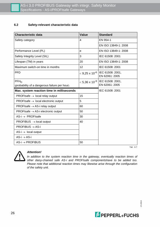
6.2 Safety-relevant characteristic data
Characteristic data Value StandardSafety category 4 EN 954-1
EN ISO 13849-1: 2008
Performance Level (PL) e EN ISO 13849-1: 2008
Safety Integrity Level (SIL) 3 IEC 61508: 2001
Lifespan (TM) in years 20 EN ISO 13849-1: 2008
Maximum switch-on time in months 12 IEC 61508: 2001
PFD < 9,25 x 10⁻⁶ IEC 61508: 2001,EN 62061: 2005
PFHD(probability of a dangerous failure per hour)
< 5,36 x 10⁻⁹ IEC 61508: 2001,EN 62061: 2005
Max. system reaction time in milliseconds IEC 61508: 2001
PROFIsafe → local relay output 15
PROFIsafe → local electronic output 5
PROFIsafe → AS-i relay output 60
PROFIsafe → AS-i electronic output 50
AS-i → PROFIsafe 30
PROFIBUS → local output 40
PROFIBUS → AS-i
AS-i → local output
AS-i → AS-i
AS-i → PROFIBUS 50 Tab. 6-7.
Attention!In addition to the system reaction time in the gateway, eventually reaction times ofother daisy-chained safe AS-i and PROFIsafe componentshave to be added too.Please note that additional reaction times may likewise arise through the configurationof the safety unit.
26
AS-i 3.0 PROFIBUS Gateway with integr. Safety MonitorSpezifications - AS-i/PROFIsafe Gateways
2.5.
2013
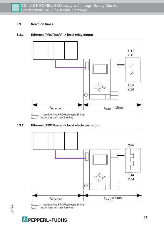
6.3 Reaction times
6.3.1 Ethernet (PROFIsafe) -> local relay output
tethernet = reaction time PROFIsafe type 150mstreact = maximal system reaction time
6.3.2 Ethernet (PROFIsafe) -> local electronic output
tethernet = reaction time PROFIsafe type 150mstreact = maximal system reaction time
treact = 15ms
1.13
2.13
1.14
2.14
tethernet
treact = 5ms
tethernet
24V
1.14
2.14
27
2.5
.201
3
AS-i 3.0 PROFIBUS Gateway with integr. Safety MonitorSpezifications - AS-i/PROFIsafe Gateways
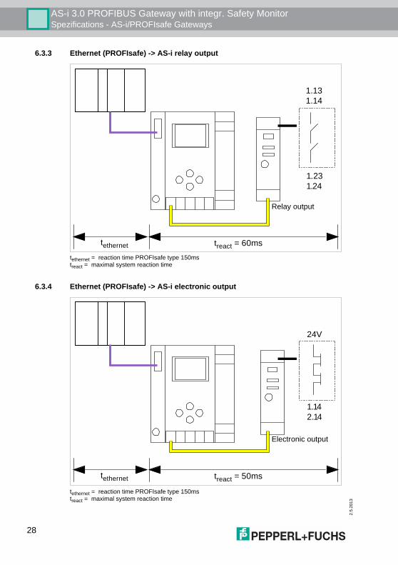
6.3.3 Ethernet (PROFIsafe) -> AS-i relay output
tethernet = reaction time PROFIsafe type 150mstreact = maximal system reaction time
6.3.4 Ethernet (PROFIsafe) -> AS-i electronic output
tethernet = reaction time PROFIsafe type 150mstreact = maximal system reaction time
treact = 60ms
tethernet
1.13
1.14
1.23
1.24
Relay output
treact = 50ms
tethernet
24V
1.14
2.14
Electronic output
28
AS-i 3.0 PROFIBUS Gateway with integr. Safety MonitorInstallation
2.5.
2013
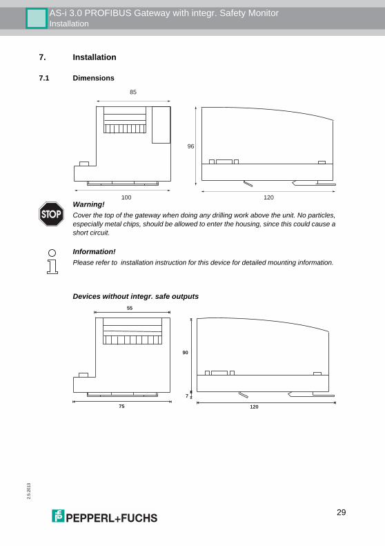
7. Installation
7.1 Dimensions
Devices without integr. safe outputs
120
96
100
85
Warning!Cover the top of the gateway when doing any drilling work above the unit. No particles,especially metal chips, should be allowed to enter the housing, since this could cause ashort circuit.
Information!Please refer to installation instruction for this device for detailed mounting information.
55
75 120
7
90
29
2.5
.201
3
AS-i 3.0 PROFIBUS Gateway with integr. Safety MonitorInstallation
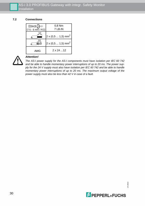
7.2 Connections
0,8 Nm
7 LB.IN5 - 6 mm / PZ2
10
10
AWG 2 x 24 ...12
2 x (0,5 ... 1,5) mm2
2 x (0,5 ... 1,5) mm2
Attention!The AS-I power supply for the AS-I components must have isolation per IEC 60 742and be able to handle momentary power interruptions of up to 20 ms. The power sup-ply for the 24 V supply must also have isolation per IEC 60 742 and be able to handlemomentary power interruptions of up to 20 ms. The maximum output voltage of thepower supply must also be less than 42 V in case of a fault.
30
AS-i 3.0 PROFIBUS Gateway with integr. Safety MonitorInstallation
2.5.
2013
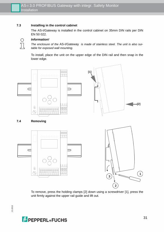
7.3 Installing in the control cabinetThe AS-I/Gateway is installed in the control cabinet on 35mm DIN rails per DINEN 50 022.
To install, place the unit on the upper edge of the DIN rail and then snap in thelower edge.
7.4 Removing
To remove, press the holding clamps [2] down using a screwdriver [1], press theunit firmly against the upper rail guide and lift out.
Information!The enclosure of the AS-I/Gateway is made of stainless steel. The unit is also sui-table for exposed wall mounting.
+ -+ - + -
[1]
[2]
+ -+ - + -
1
2
3
31
2.5
.201
3
AS-i 3.0 PROFIBUS Gateway with integr. Safety MonitorInstallation
7.5 Electrical Connection
7.6 Commissioning
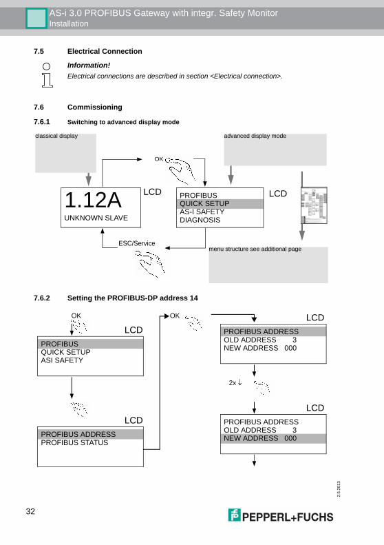
7.6.1 Switching to advanced display mode
7.6.2 Setting the PROFIBUS-DP address 14
Information!Electrical connections are described in section <Electrical connection>.
OK
ESC/Service
classical display
menu structure see additional page
LCD1.12AUNKNOWN SLAVE
LCDPROFIBUSQUICK SETUPAS-I SAFETYDIAGNOSIS
advanced display mode
LCDPROFIBUS
OK
QUICK SETUPASI SAFETY
LCDPROFIBUS ADDRESSPROFIBUS STATUS
LCDPROFIBUS ADDRESSOLD ADDRESS 3
2x ↓
OK
NEW ADDRESS 000
LCDPROFIBUS ADDRESSOLD ADDRESS 3NEW ADDRESS 000
32
AS-i 3.0 PROFIBUS Gateway with integr. Safety MonitorInstallation
2.5.
2013
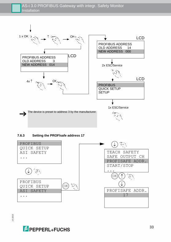
7.6.3 Setting the PROFIsafe address 17
LCDPROFIBUSQUICK SETUPSETUP
The device is preset to address 3 by the manufacturer.
LCDPROFIBUS ADDRESSOLD ADDRESS 14
2x ESC/Service
NEW ADDRESS 000
1x ESC/Service
1 x OK ↑ OK
LCDPROFIBUS ADDRESSOLD ADDRESS 3NEW ADDRESS 014
4x ↑ OK
PROFIBUSQUICK SETUPASI SAFETY...
PROFIBUSQUICK SETUPASI SAFETY...
TEACH SAFETYSAFE OUTPUT CHPROFISAFE ADDR.START/STOP...
PROFISAFE ADDR. 17
OK
↓
↓↓
OK
↓
33
2.5
.201
3
AS-i 3.0 PROFIBUS Gateway with integr. Safety MonitorInstallation
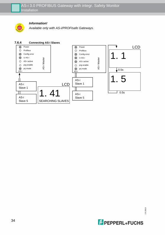
7.6.4 Connecting AS-i Slaves
Information!Available only with AS-i/PROFIsafe Gateways.
Slave 1AS-i
Slave 5AS-i
LCD
0.5s
0.5s
Slave 1AS-i
Slave 5AS-i
AS-iprj mode
Config error
prg enable
AS-i active
U AS-i
Profibus
Power
AS-iprj mode
Config error
prg enable
AS-i active
U AS-i
Profibus
Power
1. 5
1. 1A
S-i
Mas
ter
AS
-i M
aste
r
LCD
1. 41SEARCHING SLAVES
34
AS-i 3.0 PROFIBUS Gateway with integr. Safety MonitorInstallation
2.5.
2013
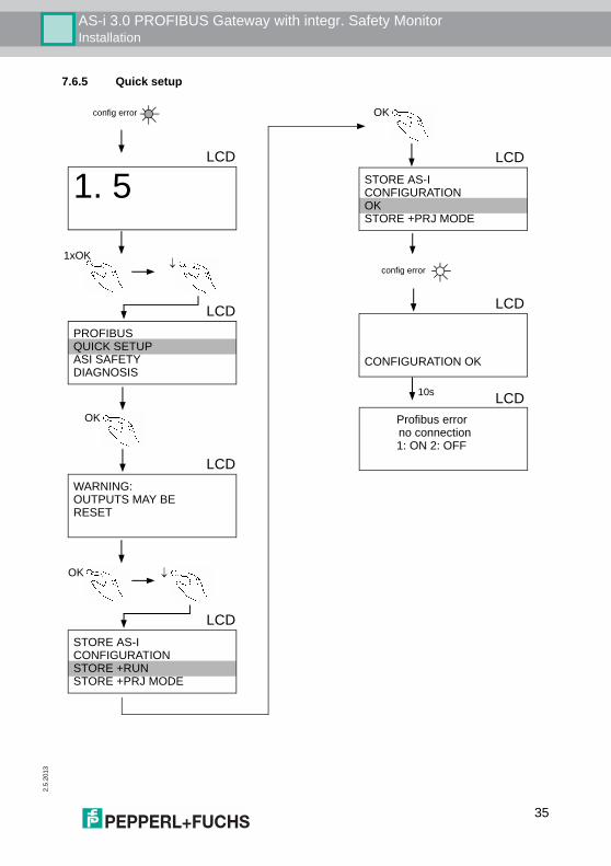
7.6.5 Quick setup
config error
LCD
CONFIGURATION OK
LCDPROFIBUSQUICK SETUPASI SAFETYDIAGNOSIS
1xOK↓
LCDWARNING:OUTPUTS MAY BERESET
OK ↓
OK
LCDSTORE AS-ICONFIGURATIONSTORE +RUN
LCDSTORE AS-ICONFIGURATIONOK
LCD
1. 5
OK
STORE +PRJ MODE
STORE +PRJ MODE
config error
Profibus errorno connection1: ON 2: OFF
LCD10s
35
2.5
.201
3
AS-i 3.0 PROFIBUS Gateway with integr. Safety MonitorInstallation
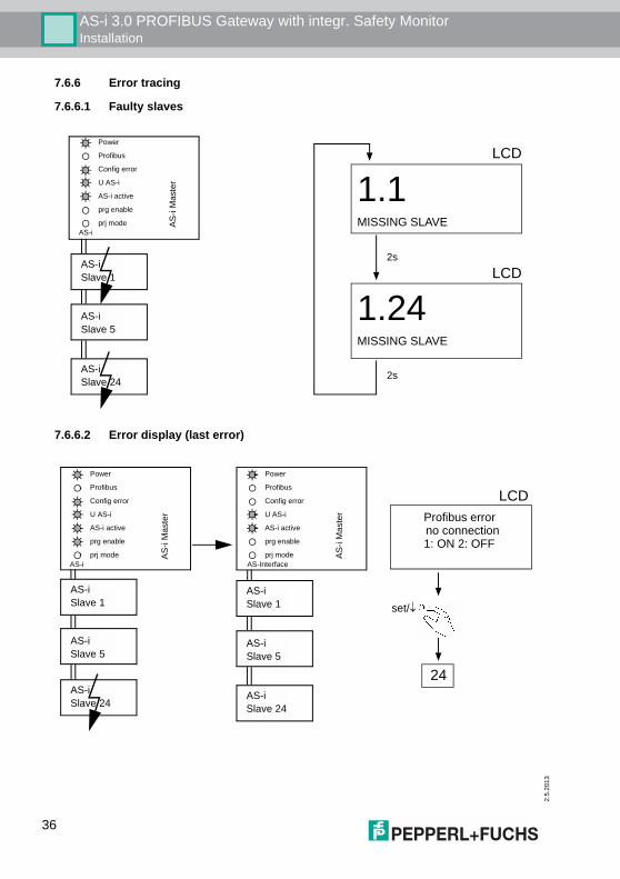
7.6.6 Error tracing
7.6.6.1 Faulty slaves
7.6.6.2 Error display (last error)
Slave 1AS-i
Slave 5AS-i
Slave 24AS-i
1.1AS-i
prj mode
Config error
prg enable
AS-i active
U AS-i
Profibus
Power
1.24
MISSING SLAVE
MISSING SLAVE
2s
2s
LCD
LCD
AS-i
Mas
ter
Slave 1AS-i
Slave 5AS-i
Slave 24AS-i
AS-Interface
24
set/↓Slave 1AS-i
Slave 5AS-i
Slave 24AS-i
AS-iprj mode
Config error
prg enable
AS-i active
U AS-i
Profibus
Power
prj mode
Config error
prg enable
AS-i active
U AS-i
Profibus
Power
AS-i
Mas
ter
AS-
i Mas
ter Profibus error
no connection1: ON 2: OFF
LCD
36
AS-i 3.0 PROFIBUS Gateway with integr. Safety MonitorInstallation
2.5.
2013
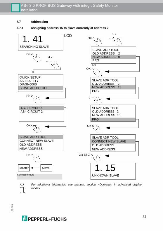
7.7 Addressing
7.7.1 Assigning address 15 to slave currently at address 2
OK
OK
OK ↓1 xLCD 1. 41
SEARCHING SLAVE
↓
QUICK SETUPAS-I SAFETYDIAGNOSIS
SLAVE ADR TOOLCONNECT NEW SLAVE
SLAVE ADR TOOLOLD ADDRESS 2NEW ADDRESS 0PRG
SLAVE ADR TOOLOLD ADDRESS 2NEW ADDRESS 15
2 x ESC
1. 15UNKNOWN SLAVE
OLD ADDRESSNEW ADDRESS
PRG
SLAVE ADR TOOLOLD ADDRESS 2NEW ADDRESS 15PRG
OK
Master Slave
Connect module
SLAVE ADDR TOOL
SLAVE ADR TOOLCONNECT NEW SLAVEOLD ADDRESSNEW ADDRESS
4 x
6 x
AS-I CIRCUIT 1AS-I CIRCUIT 2
OK
OK
OK
↓
For additional information see manual, section <Operation in advanced displaymode>.
37
2.5
.201
3
AS-i 3.0 PROFIBUS Gateway with integr. Safety MonitorInstallation
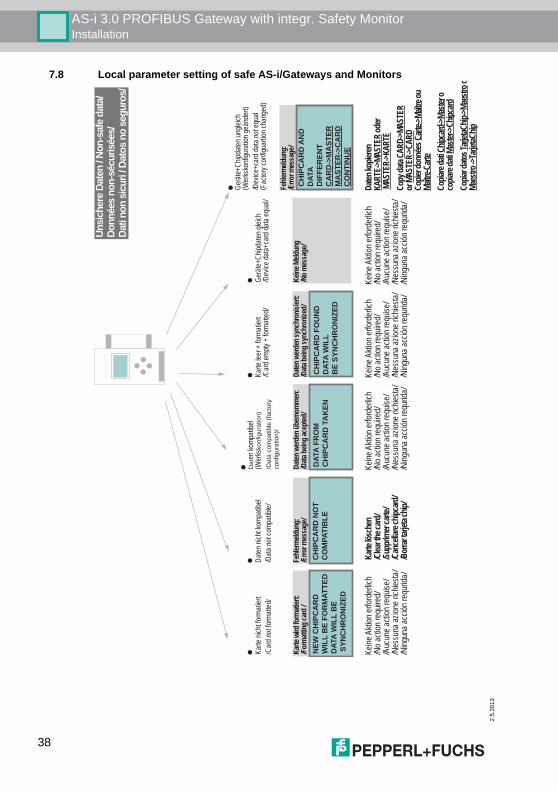
7.8 Local parameter setting of safe AS-i/Gateways and Monitors
CH
IPC
AR
D F
OU
ND
DAT
A W
ILL
BE
SYN
CH
RO
NIZ
ED
Karte
leer
+ fo
rmati
ert
/Car
d emp
ty +
forma
tted/
Dat
en w
erd
en s
ynch
ron
isie
rt:
/Dat
a b
ein
g s
ynch
ron
ized
/
NEW
CH
IPC
AR
DW
ILL
BE
FOR
MAT
TED
DAT
A W
ILL
BE
SYN
CH
RO
NIZ
ED
Karte
nich
t form
atier
t/C
ard n
ot fo
rmatt
ed/
Kar
te w
ird
form
atie
rt:
/Fo
rmat
ting
car
d /
DAT
A FR
OM
CH
IPC
AR
D T
AK
EN
Da
ten ko
mpati
bel
(Wer
ksko
nfig
ura
tio
n)
/Data
co
mp
atib
le (
facto
ry
configu
ratio
n)/
Dat
en w
erd
en ü
ber
no
mm
en:
/Dat
a b
ein
g a
cep
ted
/
CH
IPC
AR
D N
OT
CO
MPA
TIB
LE
Daten
nich
t kom
patib
el/D
ata no
t com
patib
le/
Feh
lerm
eld
un
g:
/Err
or
mes
sag
e/C
HIP
CA
RD
AN
D
DAT
AD
IFFE
REN
TC
AR
D->
MA
STER
MA
STER
->C
AR
DC
ON
TIN
UE
Gerä
te+Ch
ipdate
n ung
leich
(Wer
ksko
nfigu
ratio
n geä
nder
t)/D
evice
+car
d data
not e
qual
(Fac
tory c
onfig
uartio
n cha
nged
)
Feh
lerm
eld
un
g:
/Err
or
mes
sag
e/
Gerä
te+Ch
ipdate
n glei
ch/D
evice
data+
card
data
equa
l/
Kei
ne
Mel
du
ng
/No
mes
sag
e/
Keine
Akti
on er
forde
rlich
/No a
ction
requ
ired/
/Auc
une a
ction
requ
ise/
/Nes
suna
azion
e rich
iesta/
/Ning
una a
cción
requ
rida/
Kar
te lö
sche
n/C
lear
the
card
//S
uppr
imer
car
te/
/Can
cella
re c
hipc
ard/
/Bor
rar t
arje
ta c
hip/
Dat
en k
opie
ren
KA
RTE
->M
AS
TER
ode
r M
AS
TER
->K
AR
TE
Cop
y da
ta C
AR
D->
MA
STE
Ror
MA
STE
R->
CA
RD
Cop
ier d
onné
es C
arte
->M
aîtr
e ou
M
aîtr
e-C
arte
Cop
iare
dat
i Chi
pcar
d->M
aste
r o
copi
are
dati
Mas
ter-
>Chi
pcar
d
Cop
iar d
atos
Tar
jeta
Chi
p->M
aest
ro o
Mae
stro
->Ta
rjeta
Chi
p
Unsi
cher
e Da
ten
/ Non
-saf
e da
ta/
Donn
ées
non-
sécu
risée
s/
Dati
non
sicu
ri / D
atos
no
segu
ros/
Keine
Akti
on er
forde
rlich
/No a
ction
requ
ired/
/Auc
une a
ction
requ
ise/
/Nes
suna
azion
e rich
iesta/
/Ning
una a
cción
requ
rida/
Keine
Akti
on er
forde
rlich
/No a
ction
requ
ired/
/Auc
une a
ction
requ
ise/
/Nes
suna
azion
e rich
iesta/
/Ning
una a
cción
requ
rida/
Keine
Akti
on er
forde
rlich
/No a
ction
requ
ired/
/Auc
une a
ction
requ
ise/
/Nes
suna
azion
e rich
iesta/
/Ning
una a
cción
requ
rida/
38
AS-i 3.0 PROFIBUS Gateway with integr. Safety MonitorInstallation
2.5.
2013
CH
IPC
AR
D N
OT
CO
MPA
TIB
LEC
HIP
CA
RD
FO
UN
DSA
FETY
DAT
A W
ILL
BE
SYN
CH
RO
NIZ
ED
CH
IPC
AR
D F
OU
ND
SAFE
TY D
ATA
WIL
L B
E SY
NC
HR
ON
IZED
Sic
he
re D
ate
n a
uf
de
r
Ch
ipka
rte
nic
ht
ko
mp
atib
el
zu
m G
erä
t
/Sa
fe d
ata
on
th
e c
hip
ca
rd
no
t co
mp
atib
le t
o t
he
de
vic
e/
Feh
lerm
eld
un
g:
/Err
or
mes
sag
e/
Keine
valid
ierte
Konfi
gura
tion i
m Ge
rät +
Chip
karte
/No v
alida
ted co
nfigu
ratio
n in
the de
vice +
chip
card
/
Dat
en w
erd
en s
ynch
ron
isie
rt:
/Dat
a b
ein
g s
ynch
ron
ized
/ER
RO
R.
CH
IPC
AR
D A
ND
SA
FETY
DAT
A D
IFFE
REN
T.D
ELET
E C
HIP
CA
RD
OR
SA
FETY
DAT
A
Kon
figur
atio
n pe
r R
elea
se-C
ode
frei
gebe
n
/Val
idat
e th
e co
nfig
urat
ion
via
rele
ase
code
/
/Res
pect
er le
s in
dica
tions
de
séc
urité
exp
osée
s da
ns
le m
anue
l AS
IMO
N
/Oss
erva
re le
istr
uzio
ni d
i si
cure
zza
ripor
tate
nel
m
anua
le A
SIM
ON
/Hab
ilita
r la
conf
igur
ació
n ví
a có
digo
de
liber
ació
n/
Valid
ierte
Konfi
gura
tion i
m Ge
rät, C
hipka
rte le
er/V
alida
ted co
nfigu
ratio
n in
the de
vice,
chip
card
empty
/
Dat
en w
erd
en s
ynch
ron
isie
rt:
/Dat
a b
ein
g s
ynch
ron
ized
/
Ge
rät e
nth
ält k
eine
va
lid
iert
e
Ko
nfig
ura
tio
n
/No
va
lid
ate
d c
on
fig
ura
tio
n in
the
de
vic
e/
Stam
m-/V
ollstä
ndige
Ko
nfigu
artio
n auf
der C
hipka
rte
/Mas
ter co
nfigu
ratio
n or
comp
lete c
onfig
urati
on on
the
card
Dat
enfr
eig
abe
per
R
elea
se-C
od
e n
otw
end
ig:
/Dat
a re
leas
e vi
a re
leas
e co
de
req
uir
ed/
CO
PY B
AN
K A
TO
MO
NIT
OR
... REL
EASE
CO
DE:
1BD
F---
------
------
TYPE
CO
DE
1BD
F
O
K
Stam
m-/V
ollstä
ndige
Ko
nfigu
artio
n auf
der C
hipka
rte
entha
lten
/Mas
ter co
nfigu
ratio
n or
comp
lete c
onfig
urati
on on
the
card
Gerä
t enth
ält va
lidier
te Ko
nfigu
ratio
n, Da
ten un
gleich
/The
re is
a va
lidate
d co
nfigu
ratio
n on t
he ca
rd, d
ata
not e
qual
Beide
Kon
figur
ation
en un
gleich
/ Bo
th co
nfigu
ratio
ns no
t equ
al
Feh
lerm
eld
un
g:
/Err
or
mes
sag
e/
Keine
Akti
on er
forde
rlich
/No a
ction
requ
ired/
/Auc
une a
ction
requ
ise/
/Nes
suna
azion
e rich
iesta/
/Ning
una a
cción
requ
rida/
Keine
Akti
on er
forde
rlich
/No a
ction
requ
ired/
/Auc
une a
ction
requ
ise/
/Nes
suna
azion
e rich
iesta/
/Ning
una a
cción
requ
rida/
Keine
Akti
on er
forde
rlich
/No a
ction
requ
ired/
/Auc
une a
ction
requ
ise/
/Nes
suna
azion
e rich
iesta/
/Ning
una a
cción
requ
rida/
Kar
te lö
sche
n/C
lear
the
card
//S
uppr
imer
car
te/
/Can
cella
re c
hipc
ard/
/Bor
rar c
hip/
Dat
en lö
sche
n/C
lear
dat
a//S
uppr
imer
don
nées
//C
ance
llare
dat
i/B
orra
r dat
os
Sich
ere
Date
n / S
afe
data
/Do
nnée
s sé
curis
ées/
Da
ti si
curi
/ Dat
os s
egur
os
Stam
m-/V
ollstä
ndige
Ko
nfigu
artio
n auf
der C
hipka
rte
/Mas
ter co
nfigu
ratio
n or
comp
lete c
onfig
urati
on on
the
card
Gerä
t enth
ält va
lidier
te Ko
nfigu
ratio
n/T
here
is a
valid
ated
confi
gura
tion o
n the
card
Beide
Kon
figur
ation
en gl
eich/
Both
confi
gura
tions
iden
tical
Kei
ne
Mel
du
ng
/No
mes
sag
e/
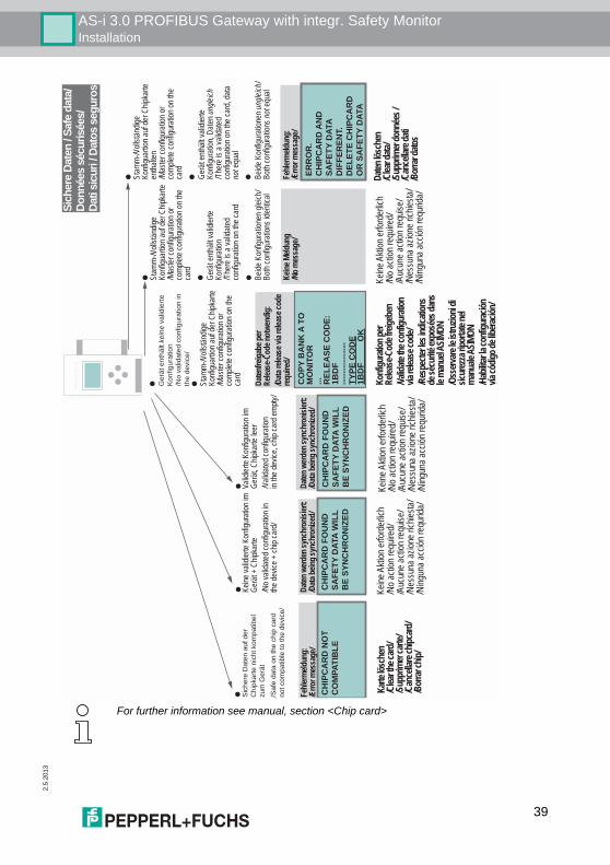
For further information see manual, section <Chip card>
39
2.5
.201
3
AS-i 3.0 PROFIBUS Gateway with integr. Safety MonitorInstallation
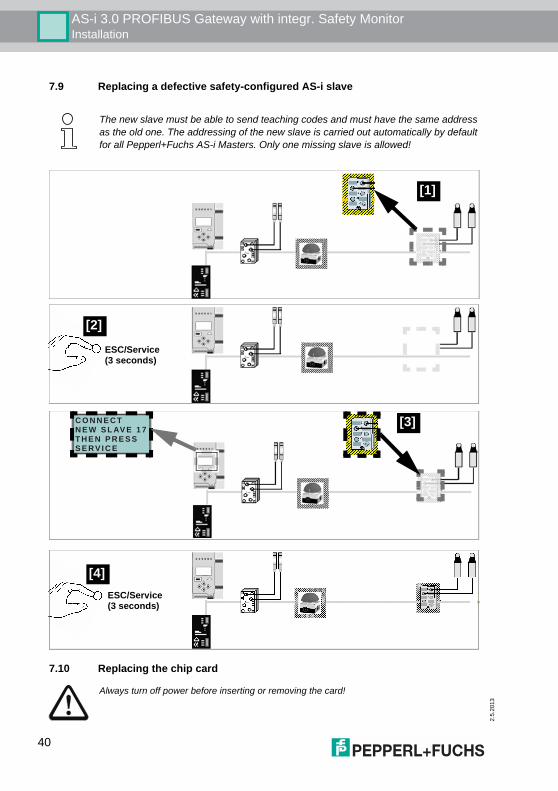
7.9 Replacing a defective safety-configured AS-i slave
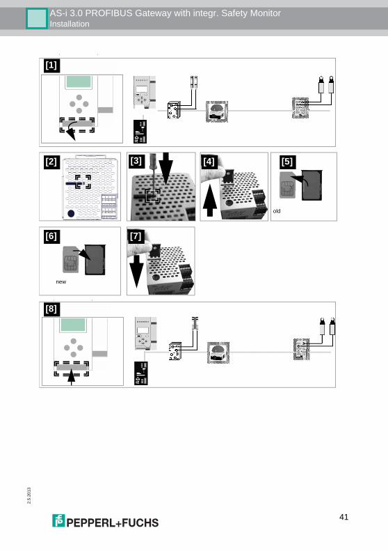
7.10 Replacing the chip card
The new slave must be able to send teaching codes and must have the same addressas the old one. The addressing of the new slave is carried out automatically by defaultfor all Pepperl+Fuchs AS-i Masters. Only one missing slave is allowed!
[1]
ESC/Service(3 seconds)
[2]
C O N N E C T N E W S L AV E 1 7T H E N P R E S S S E RV I C E
[3]
ESC/Service(3 seconds)
[4]
Always turn off power before inserting or removing the card!
40
AS-i 3.0 PROFIBUS Gateway with integr. Safety MonitorInstallation
2.5.
2013
[1]
[3] [4] [5][2]
old
[6] [7]
new
[8]
41
2.5
.201
3
AS-i 3.0 PROFIBUS Gateway with integr. Safety MonitorInstallation
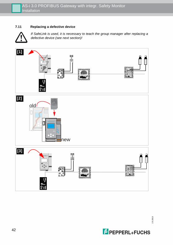
7.11 Replacing a defective device
If SafeLink is used, it is necessary to teach the group manager after replacing adefective device (see next section)!
[1]
new
old
[2]
[3]
42
AS-i 3.0 PROFIBUS Gateway with integr. Safety MonitorInstallation
2.5.
2013
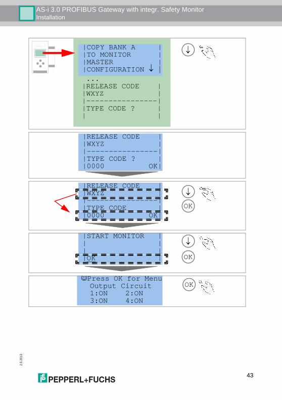
|COPY BANK A | |TO MONITOR | |MASTER | |CONFIGURATION ↓ | ... |RELEASE CODE | |WXYZ | |----------------| |TYPE CODE ? | | |
↓|COPY BANK A ||TO MONITOR ||MASTER ||CONFIGURATION ↓ |
|RELEASE CODE ||WXYZ ||----------------||TYPE CODE ? ||0000 OK|
OK
↓|RELEASE CODE ||WXYZ ||----------------||TYPE CODE ||0000 OK|
|START MONITOR || || ||OK | OK
↓
☺Press OK for Menu Output Circuit 1:ON 2:ON 3:ON 4:ON
OK
43
2.5
.201
3
AS-i 3.0 PROFIBUS Gateway with integr. Safety MonitorInstallation
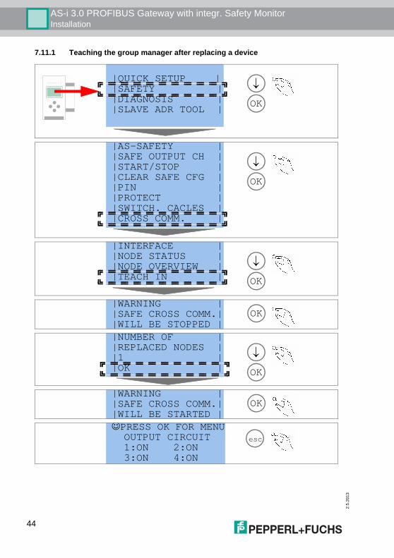
7.11.1 Teaching the group manager after replacing a device
|QUICK SETUP ||SAFETY ||DIAGNOSIS ||SLAVE ADR TOOL | OK
↓
|AS-SAFETY ||SAFE OUTPUT CH ||START/STOP ||CLEAR SAFE CFG ||PIN ||PROTECT ||SWITCH. CACLES ||CROSS COMM. |
OK
↓
|INTERFACE ||NODE STATUS ||NODE OVERVIEW ||TEACH IN | OK
↓
|WARNING ||SAFE CROSS COMM.||WILL BE STOPPED |
OK
|NUMBER OF ||REPLACED NODES ||1 ||OK | OK
↓
|WARNING ||SAFE CROSS COMM.||WILL BE STARTED |
OK
☺PRESS OK FOR MENU OUTPUT CIRCUIT 1:ON 2:ON 3:ON 4:ON
esc
44

AS-i 3.0 PROFIBUS Gateway with integr. Safety MonitorInstallation
2.5.
2013
7.12 Replacing the monitor
AS-i 1 AS-i 2
"1"+ + "2"
Monitor
"2"Monitor
"1"
[1]
AS-i 1 AS-i 2
"2"+ + "1"Monitor
"1"Monitor
"2"
[2]
Monitor
"1""2"
"1"+
Monitor
+ "2"
AS-i 1 AS-i 2
"1"+ + "2"
Monitor
"1"Monitor
"2"
45
2.5
.201
3
AS-i 3.0 PROFIBUS Gateway with integr. Safety MonitorInstallation
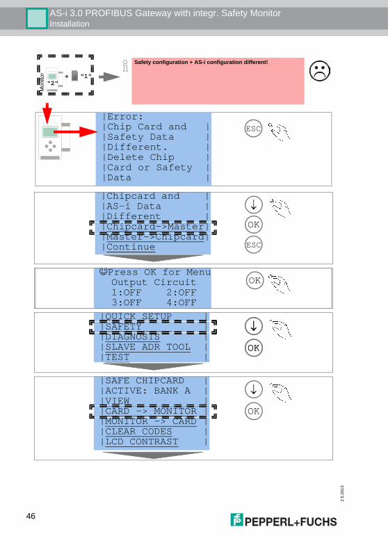
ESC|Error:|Chip Card and ||Safety Data ||Different. ||Delete Chip ||Card or Safety ||Data |
Safety configuration + AS-i configuration different!
Mon
itor
"2" + "1"
|Chipcard and ||AS-i Data ||Different ||Chipcard->Master||Master->Chipcard||Continue ESC
OK
↓
☺Press OK for Menu Output Circuit 1:OFF 2:OFF 3:OFF 4:OFF
OK
|QUICK SETUP ||SAFETY ||DIAGNOSIS ||SLAVE ADR TOOL ||TEST |
OK
↓
OK
↓
|SAFE CHIPCARD ||ACTIVE: BANK A ||VIEW ||CARD -> MONITOR ||MONITOR -> CARD ||CLEAR CODES ||LCD CONTRAST |
OK
↓
46
AS-i 3.0 PROFIBUS Gateway with integr. Safety MonitorInstallation
2.5.
2013
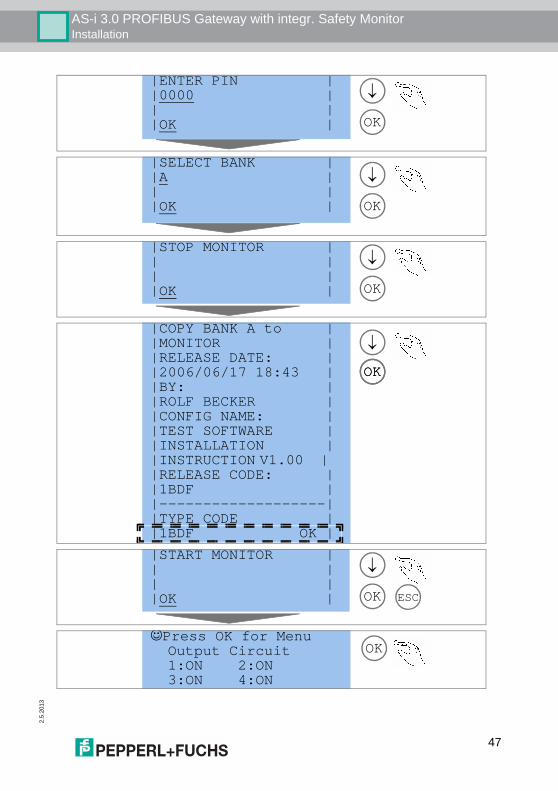
|ENTER PIN ||0000 || ||OK | OK
↓
|SELECT BANK ||A || ||OK | OK
↓
|STOP MONITOR || || ||OK | OK
↓
|COPY BANK A to ||MONITOR ||RELEASE DATE: ||2006/06/17 18:43 ||BY: ||ROLF BECKER ||CONFIG NAME: ||TEST SOFTWARE ||INSTALLATION ||INSTRUCTION V1.00 | |RELEASE CODE: ||1BDF ||-------------------||TYPE CODE ||1BDF OK |
OK
↓
OK
|START MONITOR || || ||OK | OK
↓
ESC
☺Press OK for Menu Output Circuit 1:ON 2:ON 3:ON 4:ON
OK
47
2.5
.201
3
AS-i 3.0 PROFIBUS Gateway with integr. Safety MonitorInstallation
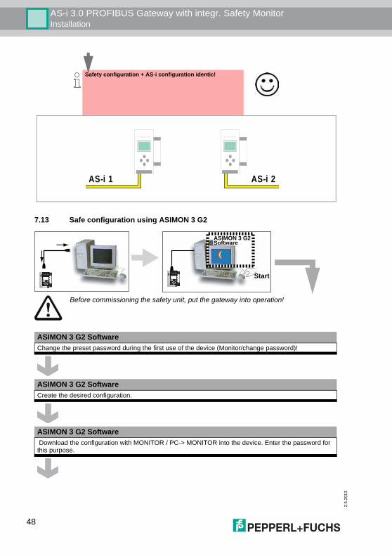
7.13 Safe configuration using ASIMON 3 G2
Safety configuration + AS-i configuration identic!
AS-i 1 AS-i 2
Before commissioning the safety unit, put the gateway into operation!
ASIMON 3 G2 Software
Start
ASIMON 3 G2 SoftwareChange the preset password during the first use of the device (Monitor/change password)!
ASIMON 3 G2 SoftwareCreate the desired configuration.
ASIMON 3 G2 Software Download the configuration with MONITOR / PC-> MONITOR into the device. Enter the password for this purpose.
48
AS-i 3.0 PROFIBUS Gateway with integr. Safety MonitorInstallation
2.5.
2013
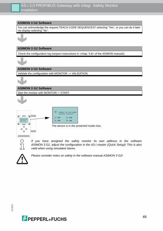
ASIMON 3 G2 SoftwareYou can acknowledge the request TEACH CODE SEQUENCES? selecting "Yes", or you can do it later via display selecting "No".
ASIMON 3 G2 SoftwareCheck the configuration log (respect instructions in <chap. 5.8> of the ASIMON manual!).
ASIMON 3 G2 SoftwareValidate the configuration with MONITOR –> VALIDATION.
ASIMON 3 G2 SoftwareStart the monitor with MONITOR–> START.
☺P r e s s O K f o r M e n u O u t p u t C i r c u i t 1 : O N 2 : O F F
☺ PRESS OK FOR MENU OUTPUT CIRCUIT
1 :ON 2:ON
3:ON 4:ON
The device is in the protected mode now.
If you have assigned the safety monitor its own address in the softwareASIMON 3 G2, adjust the configuration in the AS-i master (Quick Setup)! This is alsovalid when using simulated slaves.
Please consider notes on safety in the software manual ASIMON 3 G2!
49
2.5
.201
3
50
AS-i 3.0 PROFIBUS Gateway with integr. Safety MonitorMaintenance
8. Maintenance
8.1 Checking for safe turn-offThe safety representative is responsible for checking flawless function of the AS-iSafety Monitor within the safety system. Safe turn-off when an associated safe sensor or switch is triggered must bechecked at least once a year.Attention!To do this, actuate each safe AS-i slave and observe the switching behavior ofthe output circuits of the AS-i Safety Monitor.
Attention!Note the maximum turn-on duration and the overall turn-on operating duration.These values depend on the PFD value selected (see section <Safety-relevantcharacteristic data>).
When the maximum turn-on duration is reached (three, six or twelve months),check the complete safety system and its proper function.
When the total operating time (20 years) has been reached, the device must bereturned to the manufacturer to check for proper function.
AS-i 3.0 PROFIBUS Gateway with integr. Safety MonitorElectrical connection
2.5.
2013
9. Electrical connection
9.1 Overview of terminals, indicators and operating elements
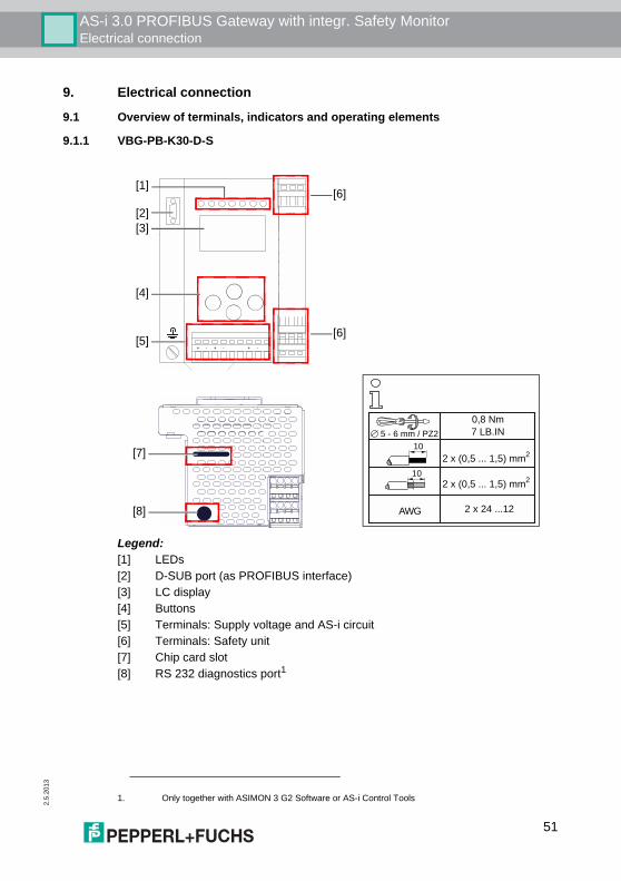
9.1.1 VBG-PB-K30-D-S
Legend:[1] LEDs[2] D-SUB port (as PROFIBUS interface)[3] LC display[4] Buttons[5] Terminals: Supply voltage and AS-i circuit[6] Terminals: Safety unit[7] Chip card slot[8] RS 232 diagnostics port1
1. Only together with ASIMON 3 G2 Software or AS-i Control Tools
+ -+ - + -
[1]
[3]
[4]
[5][6]
[2][6]
0,8 Nm
7 LB.IN5 - 6 mm / PZ2
10
10
AWG 2 x 24 ...12
2 x (0,5 ... 1,5) mm2
2 x (0,5 ... 1,5) mm2[7]
[8]
51
2.5
.201
3
AS-i 3.0 PROFIBUS Gateway with integr. Safety MonitorElectrical connection
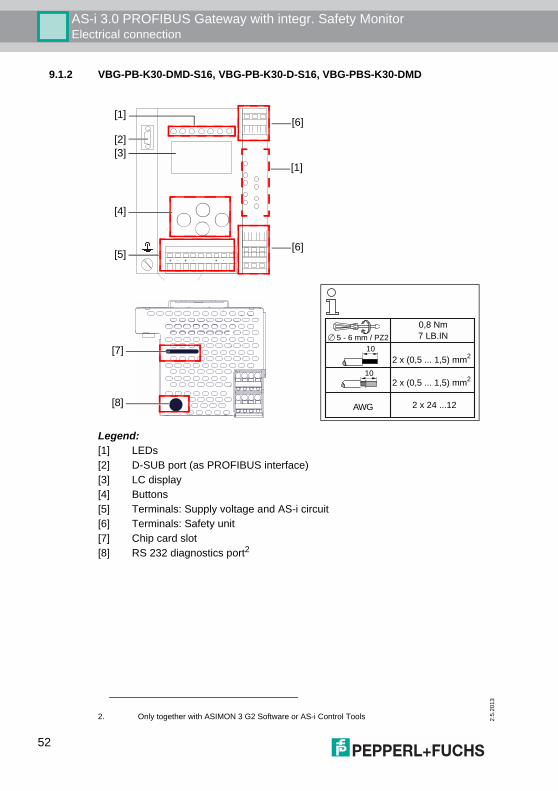
9.1.2 VBG-PB-K30-DMD-S16, VBG-PB-K30-D-S16, VBG-PBS-K30-DMD
Legend:[1] LEDs[2] D-SUB port (as PROFIBUS interface)[3] LC display[4] Buttons[5] Terminals: Supply voltage and AS-i circuit[6] Terminals: Safety unit[7] Chip card slot[8] RS 232 diagnostics port2
2. Only together with ASIMON 3 G2 Software or AS-i Control Tools
+ -+ - + -
[1]
[3]
[4]
[5][6]
[2][6]
[1]
0,8 Nm
7 LB.IN5 - 6 mm / PZ2
10
10
AWG 2 x 24 ...12
2 x (0,5 ... 1,5) mm2
2 x (0,5 ... 1,5) mm2
[7]
[8]
52
AS-i 3.0 PROFIBUS Gateway with integr. Safety MonitorElectrical connection
2.5.
2013
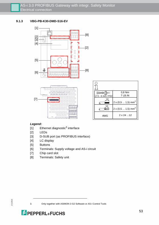
9.1.3 VBG-PB-K30-DMD-S16-EV
Legend:[1] Ethernet diagnostic3 interface[2] LEDs[3] D-SUB port (as PROFIBUS interface)[4] LC display[5] Buttons[6] Terminals: Supply voltage and AS-i circuit[7] Chip card slot[8] Terminals: Safety unit
3. Only together with ASIMON 3 G2 Software or AS-i Control Tools
+ -+ - + -
[1]
[4]
[5]
[6][8]
[3][8]
[2]
0,8 Nm
7 LB.IN5 - 6 mm / PZ2
10
10
AWG 2 x 24 ...12
2 x (0,5 ... 1,5) mm2
2 x (0,5 ... 1,5) mm2
[7]
[2]
53
2.5
.201
3
AS-i 3.0 PROFIBUS Gateway with integr. Safety MonitorElectrical connection
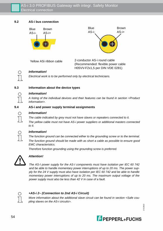
9.2 AS-i bus connection
9.3 Information about the device types
9.4 AS-i and power supply terminal assignments
Yellow ASi ribbon cable
BlueAS-i-
BrownAS-i+
2-conductor AS-i round cable(Recommended: flexible power cableH05VV-F2x1,5 per DIN VDE 0281)
BlueAS-i-
BrownAS-i+
Information!Electrical work is to be performed only by electrical technicians.
Information!A listing of the individual devices and their features can be found in section <Productinformation>.
Information!The cable indicated by grey must not have slaves or repeaters connected to it.The yellow cable must not have AS-i power suppliers or additional masters connectedto it.
Information!The function ground can be connected either to the grounding screw or to the terminal.The function ground should be made with as short a cable as possible to ensure goodEMC characteristics.Therefore function grounding using the grounding screw is preferred.
Attention!
The AS-I power supply for the AS-I components must have isolation per IEC 60 742and be able to handle momentary power interruptions of up to 20 ms. The power sup-ply for the 24 V supply must also have isolation per IEC 60 742 and be able to handlemomentary power interruptions of up to 20 ms. The maximum output voltage of thepower supply must also be less than 42 V in case of a fault.
+AS-i 2– (Connection to 2nd AS-i Circuit)More information about the additional slave circuit can be found in section <Safe cou-pling slaves on the AS-i circuits>.
54
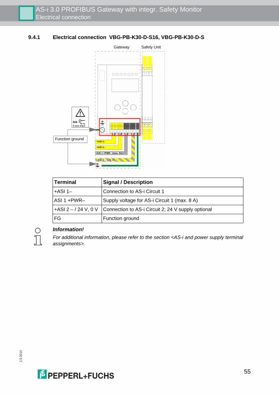
AS-i 3.0 PROFIBUS Gateway with integr. Safety MonitorElectrical connection
2.5.
2013
9.4.1 Electrical connection VBG-PB-K30-D-S16, VBG-PB-K30-D-S
+ -+ - + -
+
ASI 1 +PWR– (max. 8A)
+ASI 1–
+ASI 1–
+ASI 2– / 24V, 0V
M45 mm max!
Function ground
Gateway Safety Unit
Terminal Signal / Description+ASI 1– Connection to AS-i Circuit 1
ASI 1 +PWR– Supply voltage for AS-i Circuit 1 (max. 8 A)
+ASI 2 – / 24 V, 0 V Connection to AS-i Circuit 2; 24 V supply optional
FG Function ground
Information!For additional information, please refer to the section <AS-i and power supply terminalassignments>.
55
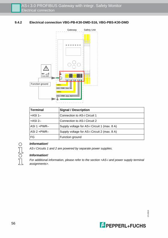
2.5
.201
3
AS-i 3.0 PROFIBUS Gateway with integr. Safety MonitorElectrical connection
9.4.2 Electrical connection VBG-PB-K30-DMD-S16, VBG-PBS-K30-DMD
+ -+ - + -
+ASI 1–
+
+ASI 2–
ASI 1 +PWR– (max. 8A)
ASI 2 +PWR– (max. 8A)
M45 mm max!
Function ground
Gateway Safety Unit
Terminal Signal / Description+ASI 1– Connection to AS-i Circuit 1
+ASI 2– Connection to AS-i Circuit 2
ASI 1 +PWR– Supply voltage for AS-i Circuit 1 (max. 8 A)
ASI 2 +PWR– Supply voltage for AS-i Circuit 2 (max. 8 A)
FG Function ground
Information!AS-i Circuits 1 and 2 are powered by separate power supplies.
Information!For additional information, please refer to the section <AS-i and power supply terminalassignments>.
56
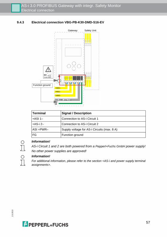
AS-i 3.0 PROFIBUS Gateway with integr. Safety MonitorElectrical connection
2.5.
2013
9.4.3 Electrical connection VBG-PB-K30-DMD-S16-EV
+ -+ - + -
+ASI 1–
+ASI 1–
+
+ASI 2–
ASI +PWR– (max. 8 A)
M45 mm max!
Function ground
Gateway Safety Unit
Terminal Signal / Description+ASI 1– Connection to AS-i Circuit 1
+AS-i 2– Connection to AS-i Circuit 2
ASI +PWR– Supply voltage for AS-i Circuits (max. 8 A)
FG Function ground
Information!AS-i Circuit 1 and 2 are both powered from a Pepperl+Fuchs GmbH power supply!No other power supplies are approved!Information!For additional information, please refer to the section <AS-i and power supply terminalassignments>.
57
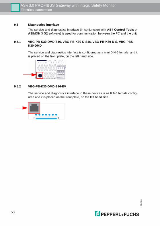
2.5
.201
3
AS-i 3.0 PROFIBUS Gateway with integr. Safety MonitorElectrical connection
9.5 Diagnostics interfaceThe service and diagnostics interface (in conjunction with AS-i Control Tools orASIMON 3 G2 software) is used for communication between the PC and the unit.
9.5.1 VBG-PB-K30-DMD-S16, VBG-PB-K30-D-S16, VBG-PB-K30-D-S, VBG-PBS-K30-DMD
The service and diagnostics interface is configured as a mini DIN-6 female and itis placed on the front plate, on the left hand side.
9.5.2 VBG-PB-K30-DMD-S16-EV
The service and diagnostics interface in these devices is as RJ45 female config-ured and it is placed on the front plate, on the left hand side.
58
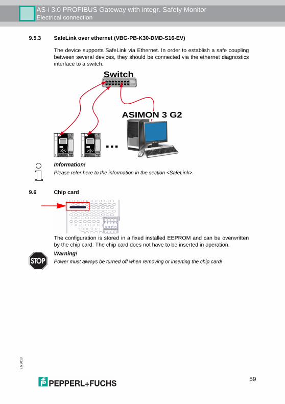
AS-i 3.0 PROFIBUS Gateway with integr. Safety MonitorElectrical connection
2.5.
2013
9.5.3 SafeLink over ethernet (VBG-PB-K30-DMD-S16-EV)
The device supports SafeLink via Ethernet. In order to establish a safe couplingbetween several devices, they should be connected via the ethernet diagnosticsinterface to a switch.
9.6 Chip card
The configuration is stored in a fixed installed EEPROM and can be overwrittenby the chip card. The chip card does not have to be inserted in operation.
Switch
ASIMON 3 G2
...Information!Please refer here to the information in the section <SafeLink>.
Warning!Power must always be turned off when removing or inserting the chip card!
59
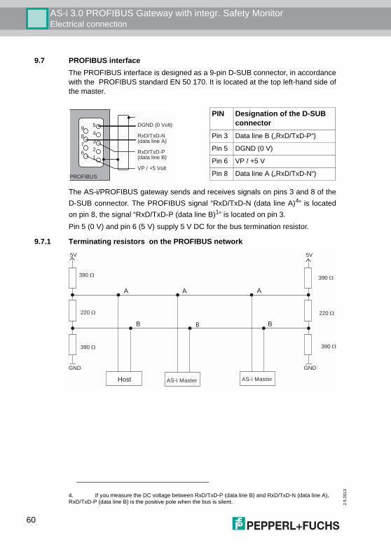
2.5
.201
3
AS-i 3.0 PROFIBUS Gateway with integr. Safety MonitorElectrical connection
9.7 PROFIBUS interfaceThe PROFIBUS interface is designed as a 9-pin D-SUB connector, in accordancewith the PROFIBUS standard EN 50 170. It is located at the top left-hand side ofthe master..
The AS-i/PROFIBUS gateway sends and receives signals on pins 3 and 8 of theD-SUB connector. The PROFIBUS signal “RxD/TxD-N (data line A)4” is locatedon pin 8, the signal “RxD/TxD-P (data line B)1” is located on pin 3.Pin 5 (0 V) and pin 6 (5 V) supply 5 V DC for the bus termination resistor.
9.7.1 Terminating resistors on the PROFIBUS network
PIN Designation of the D-SUB connector
Pin 3 Data line B („RxD/TxD-P“)
Pin 5 DGND (0 V)
Pin 6 VP / +5 V
Pin 8 Data line A („RxD/TxD-N“)PROFIBUS
DGND (0 Volt)
RxD/TxD-N(data line A)
RxD/TxD-P(data line B)
VP / +5 Volt
5
4
3
2
1
9
8
7
6
4. If you measure the DC voltage between RxD/TxD-P (data line B) and RxD/TxD-N (data line A), RxD/TxD-P (data line B) is the positive pole when the bus is silent.
A
B B B
390 Ω
220 Ω
390 Ω
Host AS-i Master
390 Ω
220 Ω
390 Ω
5V 5V
GND GND
AS-i Master
A A
60
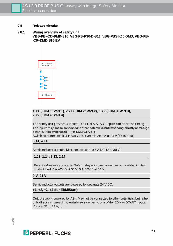
AS-i 3.0 PROFIBUS Gateway with integr. Safety MonitorElectrical connection
2.5.
2013
9.8 Release circuits
9.8.1 Wiring overview of safety unitVBG-PB-K30-DMD-S16, VBG-PB-K30-D-S16, VBG-PBS-K30-DMD, VBG-PB-K30-DMD-S16-EV
1.Y1
Aux
2.Y1
K1
K3
1.Y2
2.Y2
K2
K4
2.13
+3
24 V
2.Y1
0 V
+4
1.13
2.Y2
1.Y2
2.14
+2
4.14
+1
1.14
1.Y1
3.14
1.Y1 (EDM 1/Start 1), 2.Y1 (EDM 2/Start 2), 1.Y2 (EDM 3/Start 3), 2.Y2 (EDM 4/Start 4)
The safety unit provides 4 inputs. The EDM & START inputs can be defined freely.The inputs may not be connected to other potentials, but rather only directly or through potential-free switches to + (for EDM/START).Switching current static 4 mA at 24 V, dynamic 30 mA at 24 V (T=100 µs).
3.14, 4.14
Semiconductor outputs. Max. contact load: 0.5 A DC-13 at 30 V.
1.13, 1.14; 2.13, 2.14
Potential-free relay contacts. Safety relay with one contact set for read-back. Max. contact load: 3 A AC-15 at 30 V, 3 A DC-13 at 30 V.
0 V, 24 V
Semiconductor outputs are powered by separate 24 V DC.
+1, +2, +3, +4 (for EDM/Start)
Output supply, powered by AS-i. May not be connected to other potentials, but rather only directly or through potential-free switches to one of the EDM or START inputs. Voltage 30 ... 15 VDC.
61
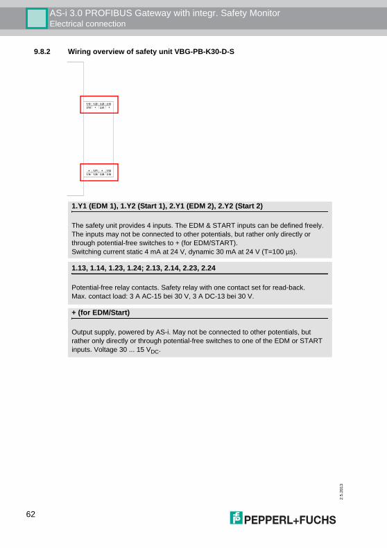
2.5
.201
3
AS-i 3.0 PROFIBUS Gateway with integr. Safety MonitorElectrical connection
9.8.2 Wiring overview of safety unit VBG-PB-K30-D-S
2.13
+
2.23
2.Y1
1.23
+
1.13
2.Y2
1.Y2
2.14
+
2.24
+
1.14
1.Y1
1.24
1.Y1 (EDM 1), 1.Y2 (Start 1), 2.Y1 (EDM 2), 2.Y2 (Start 2)
The safety unit provides 4 inputs. The EDM & START inputs can be defined freely.The inputs may not be connected to other potentials, but rather only directly or through potential-free switches to + (for EDM/START).Switching current static 4 mA at 24 V, dynamic 30 mA at 24 V (T=100 µs).
1.13, 1.14, 1.23, 1.24; 2.13, 2.14, 2.23, 2.24
Potential-free relay contacts. Safety relay with one contact set for read-back.Max. contact load: 3 A AC-15 bei 30 V, 3 A DC-13 bei 30 V.
+ (for EDM/Start)
Output supply, powered by AS-i. May not be connected to other potentials, but rather only directly or through potential-free switches to one of the EDM or START inputs. Voltage 30 ... 15 VDC.
62
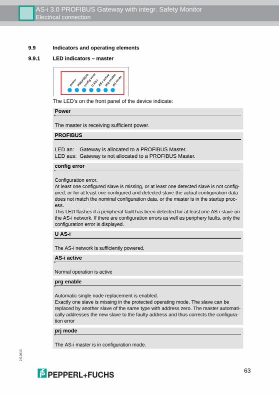
AS-i 3.0 PROFIBUS Gateway with integr. Safety MonitorElectrical connection
2.5.
2013
9.9 Indicators and operating elements
9.9.1 LED indicators – master
The LED’s on the front panel of the device indicate:
PROFIBUS
Power
The master is receiving sufficient power.
PROFIBUS
LED an: Gateway is allocated to a PROFIBUS Master.LED aus: Gateway is not allocated to a PROFIBUS Master.
config error
Configuration error.At least one configured slave is missing, or at least one detected slave is not config-ured, or for at least one configured and detected slave the actual configuration data does not match the nominal configuration data, or the master is in the startup proc-ess.This LED flashes if a peripheral fault has been detected for at least one AS-i slave on the AS-i network. If there are configuration errors as well as periphery faults, only the configuration error is displayed.
U AS-i
The AS-i network is sufficiently powered.
AS-i active
Normal operation is active
prg enable
Automatic single node replacement is enabled. Exactly one slave is missing in the protected operating mode. The slave can be replaced by another slave of the same type with address zero. The master automati-cally addresses the new slave to the faulty address and thus corrects the configura-tion error
prj mode
The AS-i master is in configuration mode.
63
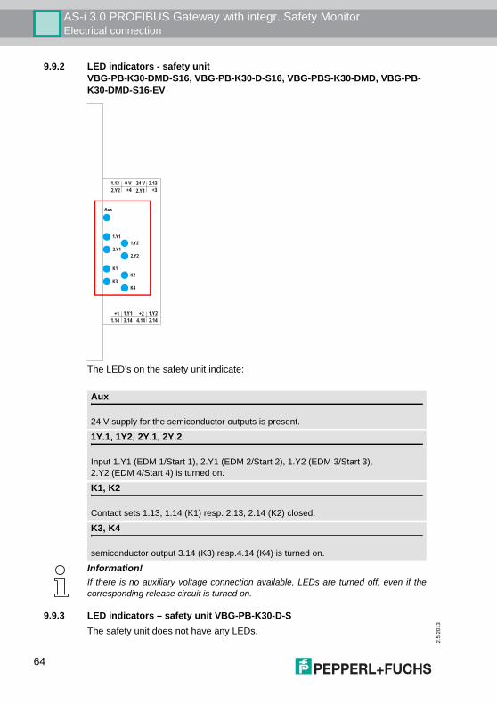
2.5
.201
3
AS-i 3.0 PROFIBUS Gateway with integr. Safety MonitorElectrical connection
9.9.2 LED indicators - safety unitVBG-PB-K30-DMD-S16, VBG-PB-K30-D-S16, VBG-PBS-K30-DMD, VBG-PB-K30-DMD-S16-EV
The LED’s on the safety unit indicate:
9.9.3 LED indicators – safety unit VBG-PB-K30-D-SThe safety unit does not have any LEDs.
1.Y1
Aux
2.Y1
K1
K3
1.Y2
2.Y2
K2
K4
2.13
+3
24 V
2.Y1
0 V
+4
1.13
2.Y2
1.Y2
2.14
+2
4.14
+1
1.14
1.Y1
3.14
Aux
24 V supply for the semiconductor outputs is present.
1Y.1, 1Y2, 2Y.1, 2Y.2
Input 1.Y1 (EDM 1/Start 1), 2.Y1 (EDM 2/Start 2), 1.Y2 (EDM 3/Start 3), 2.Y2 (EDM 4/Start 4) is turned on.
K1, K2
Contact sets 1.13, 1.14 (K1) resp. 2.13, 2.14 (K2) closed.
K3, K4
semiconductor output 3.14 (K3) resp.4.14 (K4) is turned on.
Information!If there is no auxiliary voltage connection available, LEDs are turned off, even if thecorresponding release circuit is turned on.
64
AS-i 3.0 PROFIBUS Gateway with integr. Safety MonitorElectrical connection
2.5.
2013
9.9.4 ButtonsThe buttons are used for the following:
For additional information see:• <Section <Function of the ESC/Service key>• <Section <Replacing a defective safety-configured AS-i slave>• <Section <Operation in advanced display mode>.
Mode/⇑
Switching between configuration mode and protected operating mode, and saving the current AS-i configuration as the nominal configuration.
Set/⇓
Selecting the address of and assigning an address to a slave.
OK
Change to extended mode.
ESC/Service
For teaching the code table for a new safe slave, when exactly one safe slave is being replaced, and for unlocking the Safety Monitor. This button is also used to exit extended mode.
65
2.5
.201
3
AS-i 3.0 PROFIBUS Gateway with integr. Safety MonitorFunction and startup of the Safety Monitor
10. Function and startup of the Safety Monitor
Configuration and startup of the AS-i Safety Monitor is accomplished using a PC/Notebook and the ASIMON 3 G2 configuration software.The operating language of the device can be set for the respective country (seesection <Operation in advanced display mode>).
Configuration may be performed only by a safety authorized person. All safety-re-lated commands are password protected.
10.1 Powering up the deviceAs soon as supply voltage is present on the device an internal system test is start-ed. This operating state is indicated by lighting of the upper LED row.
10.2 Configuration of the safety functionsThe device can be configured in several ways:1. Using ASIMON 3 G2 software
The ASIMON 3 G2 software represents the most universal method of con-figuring the Safety Monitor. Here the behavior of the Safety Monitor can be determined by linking various monitoring modules. After being sent to the Safety Monitor, this configuration is verified and can then be validated.For additional information, refer to the separate manual for the ASIMON 3 G2 configuration software.
2. Using a chip card with the master configurationConfigurations stored on the chip card, which are validated but which do not contain any code sequences, can be sent to the device. The code sequences must then be taught to the corresponding safety AS-i slaves.This procedure is useful when you want to use a safety program in several safety monitors without any changes.
Information!The description of the ASIMON 3 G2 software and startup of the AS-i Safety Monitorcan be found in the manual “ASIMON 3 G2 AS-i Safety Monitor Configuration Softwarefor Microsoft®-Windows®“.
The software manual is an important component of the operating manual for the AS-iSafety Monitor. It is not possible to configure and start up the AS-i Safety Monitor with-out the ASIMON 3 G2 software.
Information!For additional information refer to section <Description of configuration using chip cardwith master configuration>.
66
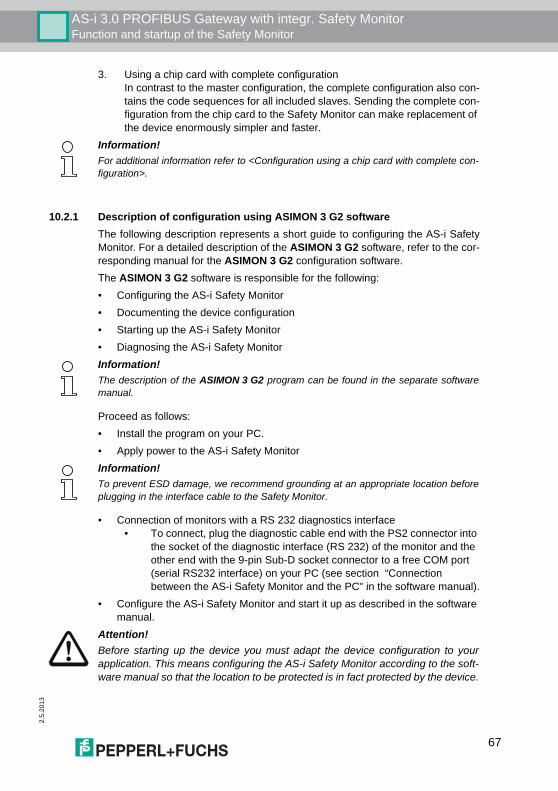
AS-i 3.0 PROFIBUS Gateway with integr. Safety MonitorFunction and startup of the Safety Monitor
2.5.
2013
3. Using a chip card with complete configurationIn contrast to the master configuration, the complete configuration also con-tains the code sequences for all included slaves. Sending the complete con-figuration from the chip card to the Safety Monitor can make replacement of the device enormously simpler and faster.
10.2.1 Description of configuration using ASIMON 3 G2 softwareThe following description represents a short guide to configuring the AS-i SafetyMonitor. For a detailed description of the ASIMON 3 G2 software, refer to the cor-responding manual for the ASIMON 3 G2 configuration software.The ASIMON 3 G2 software is responsible for the following:• Configuring the AS-i Safety Monitor• Documenting the device configuration• Starting up the AS-i Safety Monitor• Diagnosing the AS-i Safety Monitor
Proceed as follows:• Install the program on your PC.• Apply power to the AS-i Safety Monitor
• Connection of monitors with a RS 232 diagnostics interface• To connect, plug the diagnostic cable end with the PS2 connector into
the socket of the diagnostic interface (RS 232) of the monitor and the other end with the 9-pin Sub-D socket connector to a free COM port (serial RS232 interface) on your PC (see section “Connection between the AS-i Safety Monitor and the PC" in the software manual).
• Configure the AS-i Safety Monitor and start it up as described in the software manual.
Information!For additional information refer to <Configuration using a chip card with complete con-figuration>.
Information!The description of the ASIMON 3 G2 program can be found in the separate softwaremanual.
Information!To prevent ESD damage, we recommend grounding at an appropriate location beforeplugging in the interface cable to the Safety Monitor.
Attention!Before starting up the device you must adapt the device configuration to yourapplication. This means configuring the AS-i Safety Monitor according to the soft-ware manual so that the location to be protected is in fact protected by the device.
67
2.5
.201
3
AS-i 3.0 PROFIBUS Gateway with integr. Safety MonitorFunction and startup of the Safety Monitor
10.2.2 Description of configuration using chip card with master configurationGenerating a master configuration:• Generate a configuration using the ASIMON 3 G2 software• Load the configuration into the device• Release (validate) the configuration, but do not teach the code sequences• The code sequences will be taught on the physical AS-i circuit
10.2.3 Configuration using a chip card with complete configurationThe chip card contains the complete configuration if:• An empty chip cared is plugged into an AS-i Safety Monitor which already
contains a complete configuration, or• The chip card is already inserted while the configuration is being written into
the device using ASIMON 3 G2 software and before validating the code sequences.
If the AS-i Safety Monitor needs to be replaced, the stored configuration can betransferred by simply plugging the chip card from the old device into the new one.
Attention!Safety advisory:Ensure that the chip card contains the configuration intended for and released forthe application!This can be done by comparing the release codes on the display (section <Ope-ration in advanced display mode>):• The safety representative who generated and validated the release code
stores the release code for the master configuration and approves use of the configuration for specific equipment.
• The person performing the startup reads out the release code on the display before teaching the code and compares it with the release code stored and approved for the equipment.
After the chip card has been used to load the configuration into the device, thesafety functions of the device must be checked in the equipment.Checking of the release code and testing the system must be documented in wri-ting and is part of the system documentation.
68
AS-i 3.0 PROFIBUS Gateway with integr. Safety MonitorFunction and startup of the Safety Monitor
2.5.
2013
10.3 Safety-relevant documentation of the application
Proceed as follows:• Create the configuration of the AS-i Safety Monitor for your application.• Validate the configuration (done by the safety supervisor).• Print out the final configuration protocol and optionally the configuration over-
view (see Section "Configuration documentation" in the software manual).• Sign the final configuration protocol (done by the safety supervisor).• Take the protocol for the safety-relevant documentation for your application
(machine documentation) and keep it in a safe place.
10.4 Diagnostic data
Diagnostics data can be obtained in any of 4 ways:• Display• PROFIBUS• ASIMON 3 G2 software over diagnostic port
Attention!Safety advisory:Power must always be turned off when removing or inserting the chip card!Ensure that the chip card contains the configuration intended for and released forthe application!This can be done by comparing the release codes on the display (section <Ope-ration in advanced display mode>):• The safety representative who generated and validated the release code
stores the release code for the master configuration and approves use of the configuration for specific equipment.
• The person performing the startup reads out the release code on the display before starting the equipment and compares it with the release code stored and approved for the equipment.
After the chip card has been used to load the configuration into the device, thesafety functions of the device must be checked in the equipment.Checking of the release code and testing the system must be documented in wri-ting and is part of the system documentation.
Information!The detailed description of the safety-relevant documentation of the configuration foryour application can be found in the separate software manual.
Information!A detailed description of the setting for diagnostics mode is described in the section“Setting diagnostics type” in the separate manual "AS-i 3.0 Command Interface".
69
2.5
.201
3
AS-i 3.0 PROFIBUS Gateway with integr. Safety MonitorFunction and startup of the Safety Monitor
• AS-i Control Tools over diagnostic port or PROFIBUS
10.4.1 Diagnostics of release circuits 1-4 via the binary dataIf monitor slaves with base address +1 and +2 exist, the state of several OSSDsis transmitted there.
10.4.2 Switch-off historyThe switch-off history, accessible from the menu DIAGNOSTICS->INT MONI-TOR->LAST DIAGNOSTIC, is intended to make reconstruction of the reason forswitch-off easier for the user. The states of all safety-relevant AS-i slaves and alldevices at the time the state change on the output device (change from green toanother color) are stored.
10.5 Password protectionAll safety-related commands are password protected. These include:• Loading configurations into the Monitor• Stopping• Learning code sequences • Releasing• Changing the password
Monitor base address+1 assignment
Data bit Content
D0 State of output circuit 1
D1 State of message output 1
D2 State of output circuit 2
D3 State of message output 2
Monitor base address+2 assignment
Data bit Content
D0 State of output circuit 3
D1 State of message output 3
D2 State of output circuit 4
D3 State of message output 4
Information!Available only with AS-i/PROFIBUS-Gateways.
Information!No new release is necessary if when using safety-configured AS-i slaves codesequences have been newly learned using the ESC/Service key.
70

AS-i 3.0 PROFIBUS Gateway with integr. Safety MonitorFunction and startup of the Safety Monitor
2.5.
2013
10.5.1 Procedure for configuring and teaching code sequencesThe configuration is created using ASIMON 3 G2 software, loaded into the safetyunit and released. The name of the person releasing and the date are stored atthis moment. If code sequences controlled through the display are newly taught,this is secured by a PIN to prevent unintended/unauthorized changing of the codesequences.
• A PIN is a 4-digit number and can only be changed from the display, not via the ASIMON 3 G2 software.
• After entering the PIN, the display can be used to start a teaching procedure for the code sequences. The monitor stops immediately after entering the PIN. After teaching, the monitor starts after a prompt and acknowledgement on the display.
Code sequences for releasing a configuration do not necessarily have to havebeen successfully learned. It is also possible to release without code sequences,which must then be learned at a later time.Teaching the code sequences is simple to perform:• Using the ESC/Service key (See section <Replacing a defective safety-con-
figured AS-i slave>)or • Using the display (See section <Operation in advanced display mode>).
Information!For additional information see section<Replacing a defective safety-configured AS-islave>.
Action ASIMON Software On AS-i Safety MonitorConfigure and load into Safety Monitor
• • (only from chip card)
Stopping • •
Releasing • −
Starting • •
Teaching code sequences • •
Changing the password • • (only from chip card)
Changing the PIN − •
Legend:"•" = possible; "–" = not possible
Tab. 10-8.
71
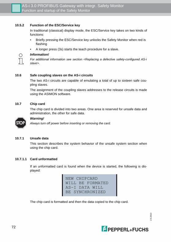
2.5
.201
3
AS-i 3.0 PROFIBUS Gateway with integr. Safety MonitorFunction and startup of the Safety Monitor
10.5.2 Function of the ESC/Service keyIn traditional (classical) display mode, the ESC/Service key takes on two kinds offunctions:• Briefly pressing the ESC/Service key unlocks the Safety Monitor when red is
flashing• A longer press (3s) starts the teach procedure for a slave.
10.6 Safe coupling slaves on the AS-i circuitsThe two AS-i circuits are capable of emulating a total of up to sixteen safe cou-pling slaves.The assignment of the coupling slaves addresses to the release circuits is madeusing the ASIMON software.
10.7 Chip cardThe chip card is divided into two areas. One area is reserved for unsafe data andadministration, the other for safe data.
10.7.1 Unsafe dataThis section describes the system behavior of the unsafe system section whenusing the chip card.
10.7.1.1 Card unformatted
If an unformatted card is found when the device is started, the following is dis-played:
The chip card is formatted and then the data copied to the chip card.
Information!For additional information see section <Replacing a defective safety-configured AS-islave>.
Warning!Always turn off power before inserting or removing the card.
NEW CHIPCARDWILL BE FORMATEDAS-I DATA WILL BE SYNCHRONIZED
72
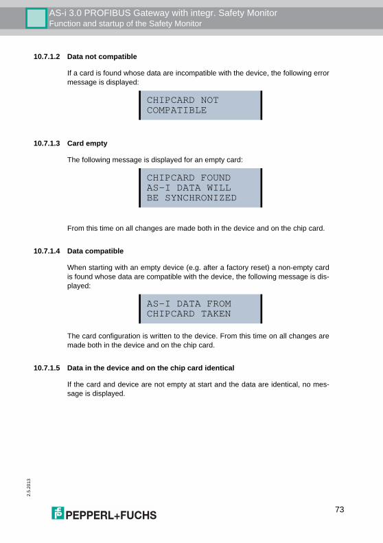
AS-i 3.0 PROFIBUS Gateway with integr. Safety MonitorFunction and startup of the Safety Monitor
2.5.
2013
10.7.1.2 Data not compatible
If a card is found whose data are incompatible with the device, the following errormessage is displayed:
10.7.1.3 Card empty
The following message is displayed for an empty card:
From this time on all changes are made both in the device and on the chip card.
10.7.1.4 Data compatible
When starting with an empty device (e.g. after a factory reset) a non-empty cardis found whose data are compatible with the device, the following message is dis-played:
The card configuration is written to the device. From this time on all changes aremade both in the device and on the chip card.
10.7.1.5 Data in the device and on the chip card identical
If the card and device are not empty at start and the data are identical, no mes-sage is displayed.
CHIPCARD NOTCOMPATIBLE
CHIPCARD FOUNDAS-I DATA WILL BE SYNCHRONIZED
AS-I DATA FROMCHIPCARD TAKEN
73
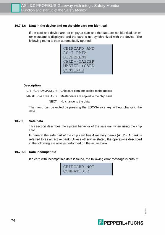
2.5
.201
3
AS-i 3.0 PROFIBUS Gateway with integr. Safety MonitorFunction and startup of the Safety Monitor
10.7.1.6 Data in the device and on the chip card not identical
If the card and device are not empty at start and the data are not identical, an er-ror message is displayed and the card is not synchronized with the device. Thefollowing menu is then automatically opened:
The menu can be exited by pressing the ESC/Service key without changing thedata.
10.7.2 Safe dataThis section describes the system behavior of the safe unit when using the chipcard.In general the safe part of the chip card has 4 memory banks (A…D). A bank isreferred to as an active bank. Unless otherwise stated, the operations describedin the following are always performed on the active bank.
10.7.2.1 Data incompatible
If a card with incompatible data is found, the following error message is output:
CHIPCARD ANDAS-I DATADIFFERENTCARD->MASTERMASTER->CARDCONTINUE
DescriptionCHIP CARD>MASTER: Chip card data are copied to the master
MASTER->CHIPCARD: Master data are copied to the chip card
NEXT: No change to the data
CHIPCARD NOTCOMPATIBLE
74
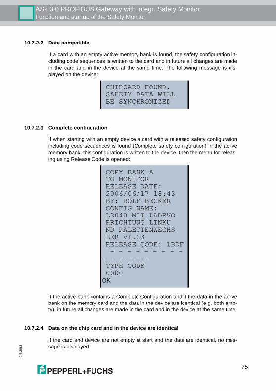
AS-i 3.0 PROFIBUS Gateway with integr. Safety MonitorFunction and startup of the Safety Monitor
2.5.
2013
10.7.2.2 Data compatible
If a card with an empty active memory bank is found, the safety configuration in-cluding code sequences is written to the card and in future all changes are madein the card and in the device at the same time. The following message is dis-played on the device:
10.7.2.3 Complete configuration
If when starting with an empty device a card with a released safety configurationincluding code sequences is found (Complete safety configuration) in the activememory bank, this configuration is written to the device, then the menu for releas-ing using Release Code is opened:
If the active bank contains a Complete Configuration and if the data in the activebank on the memory card and the data in the device are identical (e.g. both emp-ty), in future all changes are made in the card and in the device at the same time.
10.7.2.4 Data on the chip card and in the device are identical
If the card and device are not empty at start and the data are identical, no mes-sage is displayed.
CHIPCARD FOUND.SAFETY DATA WILLBE SYNCHRONIZED
COPY BANK ATO MONITORRELEASE DATE:2006/06/17 18:43BY: ROLF BECKERCONFIG NAME:L3040 MIT LADEVORRICHTUNG LINKUND PALETTENWECHSLER V1.23RELEASE CODE: 1BDF - - - - - - - - - - - - - - -TYPE CODE 0000 OK
75
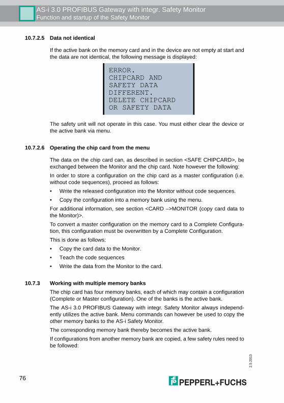
2.5
.201
3
AS-i 3.0 PROFIBUS Gateway with integr. Safety MonitorFunction and startup of the Safety Monitor
10.7.2.5 Data not identical
If the active bank on the memory card and in the device are not empty at start andthe data are not identical, the following message is displayed:
The safety unit will not operate in this case. You must either clear the device orthe active bank via menu.
10.7.2.6 Operating the chip card from the menu
The data on the chip card can, as described in section <SAFE CHIPCARD>, beexchanged between the Monitor and the chip card. Note however the following:In order to store a configuration on the chip card as a master configuration (i.e.without code sequences), proceed as follows:• Write the released configuration into the Monitor without code sequences.• Copy the configuration into a memory bank using the menu. For additional information, see section <CARD –>MONITOR (copy card data tothe Monitor)>.To convert a master configuration on the memory card to a Complete Configura-tion, this configuration must be overwritten by a Complete Configuration.This is done as follows:• Copy the card data to the Monitor.• Teach the code sequences• Write the data from the Monitor to the card.
10.7.3 Working with multiple memory banksThe chip card has four memory banks, each of which may contain a configuration(Complete or Master configuration). One of the banks is the active bank. The AS-i 3.0 PROFIBUS Gateway with integr. Safety Monitor always independ-ently utilizes the active bank. Menu commands can however be used to copy theother memory banks to the AS-i Safety Monitor.The corresponding memory bank thereby becomes the active bank.If configurations from another memory bank are copied, a few safety rules need tobe followed:
ERROR.CHIPCARD AND SAFETY DATADIFFERENT.DELETE CHIPCARDOR SAFETY DATA
76
AS-i 3.0 PROFIBUS Gateway with integr. Safety MonitorFunction and startup of the Safety Monitor
2.5.
2013
Attention!Safety advisory:Ensure that the configuration intended for and released for the application isused!This can be done by comparing the release codes on the display (See section<MONITOR CONFIG>):• The safety representative who generated and validated the configuration
stores the release code for the configuration (Complete or Master) stores the release code for the configuration and approves use of the configuration for specific equipment.
• The person performing the startup reads out the release code on the display before starting the equipment or before teaching the code sequences in the case of master configurations and compares it with the release code released for the equipment.
After the chip card has been used to load the configuration into the device, thesafety functions of the device must be checked in the equipment.Checking of the release code and testing the system must be documented in wri-ting and is part of the system documentation.
77

2.5
.201
3
78
AS-i 3.0 PROFIBUS Gateway with integr. Safety MonitorOperation in advanced display mode
11. Operation in advanced display mode
Information!You will find a description of the display menu in the separate document"Display_Menue".
AS-i 3.0 PROFIBUS Gateway with integr. Safety MonitorAdvanced Diagnostics for AS-i Masters
2.5.
2013
12. Advanced Diagnostics for AS-i Masters
The advanced AS-i diagnostics is intended to localize occasionally occurring con-figuration errors and to determine the quality of data transmission on AS-i withoutusing additional diagnostics tools.AS-i Control Tools, a MS-Windows software designed to simplify AS-i installationand used to program AS-i Control, enables operation of the advanced diagnosticsfunctions (LCS, error counters, and LOS).
12.1 List of corrupted AS-i Slaves (LCS)The LCS contains the information from the Delta list. In addition to the list of con-figured slaves (LPS), the list of detected slaves (LDS), and the list of activatedslaves (LAS), the AS-i master creates a fourth list, the list of corrupted slaves(LCS) containing advanced diagnostics data used to diagnose the causes for in-termittently occurring configuration errors on AS-i. This list contains entries for allAS-i slaves that were responsible for at least one intermittent configuration errorsince the list was last read or since the AS-i master was turned on. Furthermore,intermittent AS-i power failures are listed in the LCS at the position of AS-i slavewith address 0.
12.2 Protocol analysis: Counters for corrupted data telegramsThe AS-i master with advanced diagnostics provides a counter for telegram repe-titions for each AS-i slave. The counter counts up every time a corrupted data tel-egram has been found, making it possible to determine the quality of the trans-mission if only a few telegrams are corrupt and the AS-i slave never caused aconfiguration error.
Displaying the protocol analysis is possible through the AS-i Control Tools soft-ware by using the command "Master | AS-i Diagnostics".
Information!Whenever the LCS is read it is deleted from memory.
Information!The last intermittent configuration error can also be displayed on the AS-i master:Pressing the "Set" button on the AS-i master initiates the display of the AS-i slaveresponsible for the last intermittent configuration error. If a intermittent AS-i power fail-ure occurred, the display shows 39 after pressing the "Set" button.This function is only available if the device is in normal operating mode of the protectedmode (display empty) or in the off-line phase (Display: "40").
Information!The counter values are read via the host interface and will be deleted after they wereread.The highest possible counter value is 254. 255 indicates a counter overflow.
79
2.5
.201
3
AS-i 3.0 PROFIBUS Gateway with integr. Safety MonitorAdvanced Diagnostics for AS-i Masters
12.3 Offline Phase for Configuration ErrorsThe AS-i masters with advanced diagnostics offer the possibility to set them-selves into the offline phase when a configuration error occurs and thus are ableto transition the AS-i network into a safe operational state. This ensures a quickreaction to a configuration error and the host can be relieved from this task. If anyproblems occur on the AS-i network, the AS-i masters can independently switchthe AS-interface into a safe state.There are two different ways to parameterize the AS-i master for this feature:• Any configuration error occurring on AS-i switches the master from regular
operation in protected mode into the offline phase. • o . A list with the addresses of slaves that can potential initiate the off-line
phase is defined (list of offline slaves LOS).The user can decide how the system should react to a configuration error on AS-i. Thus, the AS-i master can be set to the offline phase for critical AS-i slaves,whereas for less critical slaves only the error message is sent to the host, but AS-i is still running. Like the advanced diagnostics, the parameterization "offline phase on configura-tion error" is also supported by "AS-i-Control-Tools"(Command | Characteristics | Offline because of configuration error).There are two options to reset the error message "OFFLINE BY LOS:1. Deleting the complete LOS list on the affected AS-i network ("CLEAR ALL").2. Power reset on the affected AS-i network.
12.4 Functions of the AS-i Fault Detector
12.4.1 Duplicate address detectionIf two slaves on an AS-i network have the same address, a duplicate address ex-ists. Since the master cannot communicate individually with these slaves anylonger, this is considered an error. Because the two slave replies interfere, it is im-possible for the master to recognize the slave responses. This results in extreme-ly unstable network behavior.The duplicate address detection function is used to safely recognize a duplicateaddress and to display it on the screen and in AS-i Control Tools.A duplicate address causes a configuration error and is displayed on the screen.
Attention!If a power reset occurs on the AS-i network 1 the complete double gateway willbe shut down.
Information!Duplicate addresses can be recognized only on an AS-i segment directly connected tothe master.
80
AS-i 3.0 PROFIBUS Gateway with integr. Safety MonitorAdvanced Diagnostics for AS-i Masters
2.5.
2013
12.4.2 Earth/Ground Fault DetectorAn Earth/Ground Fault exists when the voltage UGND (Nominal value of UGND=0,5 UAS-i.) is outside of the following range:
10% UAS-i ≤ UGND ≤ 90% UAS-i
This error substantially limits the noise immunity of the AS-i communication.Ground faults are indicated on the master´s display as well as in AS-i ControlTools.
12.4.3 Noise DetectorThe noise detector detects AC voltages on AS-i, that are not initiated by an AS-imaster or AS-i slaves. These interference voltages can cause telegram distur-bances.A frequent cause are insufficiently shielded frequency inverters or improperlyrouted cables.Noises is indicated on the master´s display as well as in AS-i Control Tools.
12.4.4 Over-voltage DetectorOver-voltages are present if the conductors of an AS-i network that normally arerouted electrically symmetrical with respect to machine ground, are strongly elec-trically raised. A cause can for example be startup procedures of large consum-ers.However, over-voltages do generally not interfere with the AS-i communication,but can under certain circumstances cause incorrect sensor signals.Over-voltages are indicated on the master´s display as well as in the AS-i ControlTools.
Information!To recognize ground faults the master must be grounded with its machine ground con-nection.
Information!A ground fault in one of the two networks of a double master in a version 1 power sup-ply for two AS-i networks causes a ground fault in the other network as well because ofthe the existing galvanic connection.
81
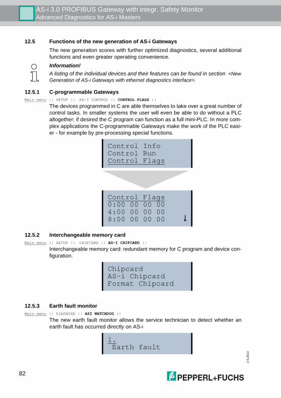
2.5
.201
3
AS-i 3.0 PROFIBUS Gateway with integr. Safety MonitorAdvanced Diagnostics for AS-i Masters
12.5 Functions of the new generation of AS-i GatewaysThe new generation scores with further optimized diagnostics, several additionalfunctions and even greater operating convenience.
12.5.1 C-programmable GatewaysMain menu || SETUP || AS-I CONTROL || CONTROL FLAGS ||
The devices programmed in C are able themselves to take over a great number ofcontrol tasks. In smaller systems the user will even be able to do without a PLCaltogether: if desired the C program can function as a full mini-PLC. In more com-plex applications the C-programmable Gateways make the work of the PLC easi-er - for example by pre-processing special functions.
12.5.2 Interchangeable memory cardMain menu || SETUP || CHIPCARD || AS-I CHIPCARD ||
Interchangeable memory card: redundant memory for C program and device con-figuration.
12.5.3 Earth fault monitorMain menu || DIAGNOSE || ASI WATCHDOG ||
The new earth fault monitor allows the service technician to detect whether anearth fault has occurred directly on AS-i
Information!A listing of the individual devices and their features can be found in section <NewGeneration of AS-i Gateways with ethernet diagnostics interface>.
Control InfoControl RunControl Flags
Control Flags0:00 00 00 004:00 00 00 008:00 00 00 00 !
ChipcardAS-i ChipcardFormat Chipcard
1. Earth fault
82
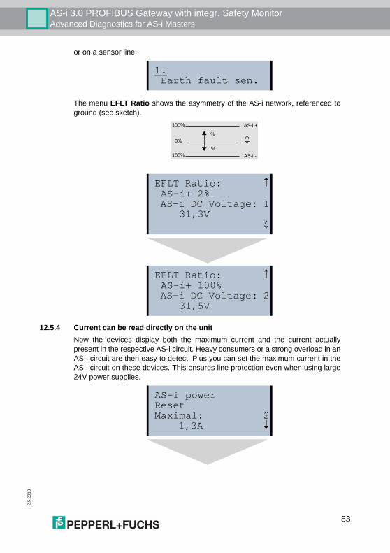
AS-i 3.0 PROFIBUS Gateway with integr. Safety MonitorAdvanced Diagnostics for AS-i Masters
2.5.
2013
or on a sensor line.
The menu EFLT Ratio shows the asymmetry of the AS-i network, referenced toground (see sketch).
12.5.4 Current can be read directly on the unitNow the devices display both the maximum current and the current actuallypresent in the respective AS-i circuit. Heavy consumers or a strong overload in anAS-i circuit are then easy to detect. Plus you can set the maximum current in theAS-i circuit on these devices. This ensures line protection even when using large24V power supplies.
1. Earth fault sen.
EFLT Ratio: " AS-i+ 2% AS-i DC Voltage: 1 31,3V $
EFLT Ratio: " AS-i+ 100% AS-i DC Voltage: 2 31,5V
AS-i +
AS-i -
0%
100%
%
%
100%
AS-i powerResetMaximal: 2 1,3A !
83
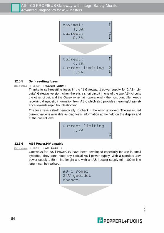
2.5
.201
3
AS-i 3.0 PROFIBUS Gateway with integr. Safety MonitorAdvanced Diagnostics for AS-i Masters
12.5.5 Self-resetting fusesMain menu || SETUP || CURRENT LIMIT ||
Thanks to self-resetting fuses in the "1 Gateway, 1 power supply for 2 AS-i cir-cuits" Gateway version, when there is a short circuit in one of the two AS-i circuitsthe other circuit and the Gateway remain operational - the host controller keepsreceiving diagnostic information from AS-i, which also provides meaningful assist-ance towards rapid troubleshooting.The fuse resets itself periodically to check if the error is solved. The measuredcurrent value is available as diagnostic information at the field on the display andat the control level.
12.5.6 AS-i Power24V capableMain menu || SETUP || ASI POWER ||
Gateways for AS-i Power24V have been developed especially for use in smallsystems. They don‘t need any special AS-i power supply. With a standard 24Vpower supply a 50 m line lenght and with an AS-i power supply min. 100 m linelenght can be realised.
Maximal: " 1,3Acurrent: 2 0,3A !
Current: " 0,3ACurrent limiting 2 3,2A !
Current limiting 3,2A 2
AS-i Power24V geerdetchange
84
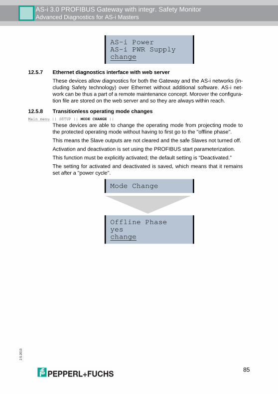
AS-i 3.0 PROFIBUS Gateway with integr. Safety MonitorAdvanced Diagnostics for AS-i Masters
2.5.
2013
12.5.7 Ethernet diagnostics interface with web serverThese devices allow diagnostics for both the Gateway and the AS-i networks (in-cluding Safety technology) over Ethernet without additional software. AS-i net-work can be thus a part of a remote maintenance concept. Morover the configura-tion file are stored on the web server and so they are always within reach.
12.5.8 Transitionless operating mode changesMain menu || SETUP || MODE CHANGE ||
These devices are able to change the operating mode from projecting mode tothe protected operating mode without having to first go to the "offline phase".This means the Slave outputs are not cleared and the safe Slaves not turned off.Activation and deactivation is set using the PROFIBUS start parameterization.This function must be explicitly activated; the default setting is “Deactivated.”The setting for activated and deactivated is saved, which means that it remainsset after a "power cycle".
AS-i PowerAS-i PWR Supplychange
Mode Change
Offline Phaseyeschange
85
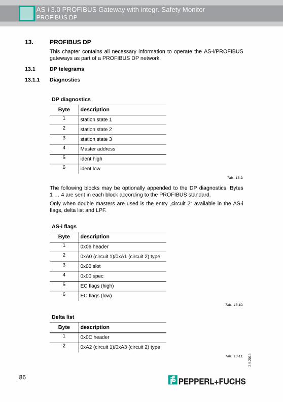
2.5
.201
3
AS-i 3.0 PROFIBUS Gateway with integr. Safety MonitorPROFIBUS DP
13. PROFIBUS DP This chapter contains all necessary information to operate the AS-i/PROFIBUSgateways as part of a PROFIBUS DP network.
13.1 DP telegrams
13.1.1 Diagnostics
The following blocks may be optionally appended to the DP diagnostics. Bytes1 … 4 are sent in each block according to the PROFIBUS standard.Only when double masters are used is the entry „circuit 2“ available in the AS-iflags, delta list and LPF.
DP diagnostics
Byte description1 station state 1
2 station state 2
3 station state 3
4 Master address
5 ident high
6 ident low
Tab. 13-9.
AS-i flags
Byte description1 0x06 header
2 0xA0 (circuit 1)/0xA1 (circuit 2) type
3 0x00 slot
4 0x00 spec
5 EC flags (high)
6 EC flags (low)
Tab. 13-10.
Delta list
Byte description1 0x0C header
2 0xA2 (circuit 1)/0xA3 (circuit 2) type
Tab. 13-11.
86
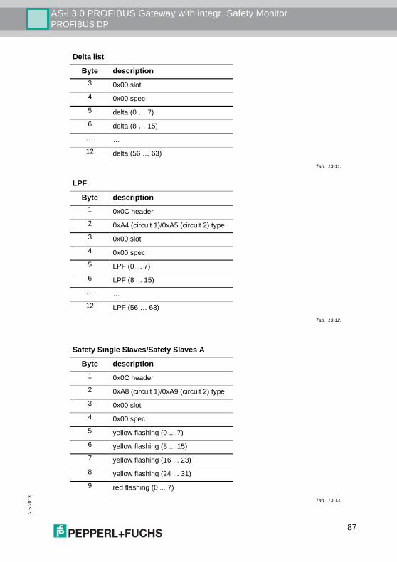
AS-i 3.0 PROFIBUS Gateway with integr. Safety MonitorPROFIBUS DP
2.5.
2013
3 0x00 slot
4 0x00 spec
5 delta (0 … 7)
6 delta (8 … 15)
… …
12 delta (56 … 63)
LPF
Byte description1 0x0C header
2 0xA4 (circuit 1)/0xA5 (circuit 2) type
3 0x00 slot
4 0x00 spec
5 LPF (0 ... 7)
6 LPF (8 ... 15)
… …
12 LPF (56 … 63)
Tab. 13-12.
Safety Single Slaves/Safety Slaves A
Byte description1 0x0C header
2 0xA8 (circuit 1)/0xA9 (circuit 2) type
3 0x00 slot
4 0x00 spec
5 yellow flashing (0 ... 7)
6 yellow flashing (8 ... 15)
7 yellow flashing (16 ... 23)
8 yellow flashing (24 ... 31)
9 red flashing (0 ... 7)
Tab. 13-13.
Delta list
Byte description
Tab. 13-11.
87
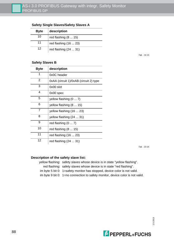
2.5
.201
3
AS-i 3.0 PROFIBUS Gateway with integr. Safety MonitorPROFIBUS DP
10 red flashing (8 ... 15)
11 red flashing (16 ... 23)
12 red flashing (24 ... 31)
Safety Slaves B
Byte description1 0x0C header
2 0xAA (circuit 1)/0xAB (circuit 2) type
3 0x00 slot
4 0x00 spec
5 yellow flashing (0 ... 7)
6 yellow flashing (8 ... 15)
7 yellow flashing (16 ... 23)
8 yellow flashing (24 ... 31)
9 red flashing (0 ... 7)
10 red flashing (8 ... 15)
11 red flashing (16 ... 23)
12 red flashing (24 ... 31)
Tab. 13-14.
Description of the safety slave list:yellow flashing: safety slaves whose device is in state "yellow flashing".
red flashing: safety slaves whose device is in state "red flashing".im byte 5 bit 0: 1=safety monitor has stopped, device color is not valid. im byte 9 bit 0: 1=no connection to safety monitor, device color is not valid.
Safety Single Slaves/Safety Slaves A
Byte description
Tab. 13-13.
88
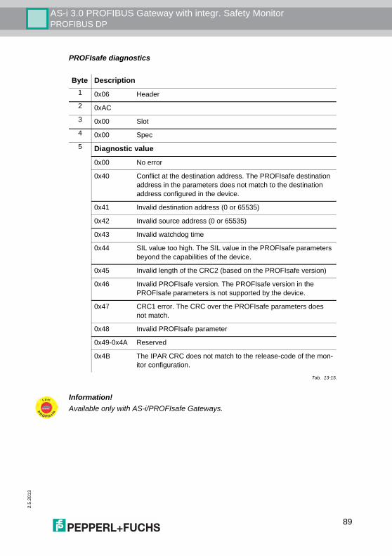
AS-i 3.0 PROFIBUS Gateway with integr. Safety MonitorPROFIBUS DP
2.5.
2013
PROFIsafe diagnostics
Byte Description1 0x06 Header
2 0xAC
3 0x00 Slot
4 0x00 Spec
5 Diagnostic value
0x00 No error
0x40 Conflict at the destination address. The PROFIsafe destination address in the parameters does not match to the destination address configured in the device.
0x41 Invalid destination address (0 or 65535)
0x42 Invalid source address (0 or 65535)
0x43 Invalid watchdog time
0x44 SIL value too high. The SIL value in the PROFIsafe parameters beyond the capabilities of the device.
0x45 Invalid length of the CRC2 (based on the PROFIsafe version)
0x46 Invalid PROFIsafe version. The PROFIsafe version in the PROFIsafe parameters is not supported by the device.
0x47 CRC1 error. The CRC over the PROFIsafe parameters does not match.
0x48 Invalid PROFIsafe parameter
0x49-0x4A Reserved
0x4B The IPAR CRC does not match to the release-code of the mon-itor configuration.
Tab. 13-15.
Information!Available only with AS-i/PROFIsafe Gateways.
89
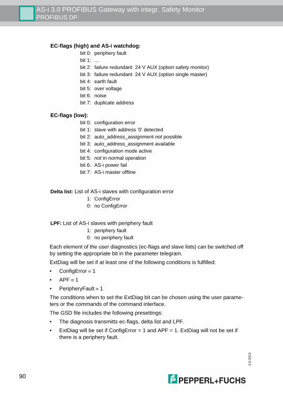
2.5
.201
3
AS-i 3.0 PROFIBUS Gateway with integr. Safety MonitorPROFIBUS DP
Each element of the user diagnostics (ec-flags and slave lists) can be switched offby setting the appropriate bit in the parameter telegram.ExtDiag will be set if at least one of the following conditions is fulfilled:• ConfigError ≡ 1• APF ≡ 1• PeripheryFault ≡ 1The conditions when to set the ExtDiag bit can be chosen using the user parame-ters or the commands of the command interface.The GSD file includes the following presettings:• The diagnosis transmitts ec-flags, delta list and LPF.• ExtDiag will be set if ConfigError = 1 and APF = 1. ExtDiag will not be set if
there is a periphery fault.
EC-flags (high) and AS-i watchdog:bit 0: periphery faultbit 1: …bit 2: failure redundant 24 V AUX (option safety monitor)bit 3: failure redundant 24 V AUX (option single master)bit 4: earth faultbit 5: over voltagebit 6: noisebit 7: duplicate address
EC-flags (low):bit 0: configuration errorbit 1: slave with address ’0’ detectedbit 2: auto_address_assignment not possiblebit 3: auto_address_assignment availablebit 4: configuration mode activebit 5: not in normal operationbit 6: AS-i power failbit 7: AS-i master offline
Delta list: List of AS-i slaves with configuration error1: ConfigError0: no ConfigError
LPF: List of AS-i slaves with periphery fault1: periphery fault0: no periphery fault
90
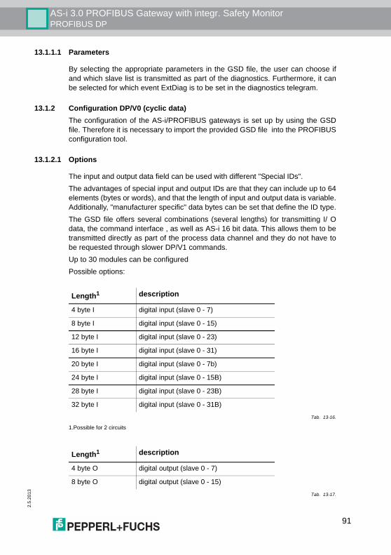
AS-i 3.0 PROFIBUS Gateway with integr. Safety MonitorPROFIBUS DP
2.5.
2013
13.1.1.1 Parameters
By selecting the appropriate parameters in the GSD file, the user can choose ifand which slave list is transmitted as part of the diagnostics. Furthermore, it canbe selected for which event ExtDiag is to be set in the diagnostics telegram.
13.1.2 Configuration DP/V0 (cyclic data)The configuration of the AS-i/PROFIBUS gateways is set up by using the GSDfile. Therefore it is necessary to import the provided GSD file into the PROFIBUSconfiguration tool.
13.1.2.1 Options
The input and output data field can be used with different "Special IDs".The advantages of special input and output IDs are that they can include up to 64elements (bytes or words), and that the length of input and output data is variable.Additionally, "manufacturer specific" data bytes can be set that define the ID type.The GSD file offers several combinations (several lengths) for transmitting I/ Odata, the command interface , as well as AS-i 16 bit data. This allows them to betransmitted directly as part of the process data channel and they do not have tobe requested through slower DP/V1 commands.Up to 30 modules can be configuredPossible options:
Length1
1.Possible for 2 circuits
description
4 byte I digital input (slave 0 - 7)
8 byte I digital input (slave 0 - 15)
12 byte I digital input (slave 0 - 23)
16 byte I digital input (slave 0 - 31)
20 byte I digital input (slave 0 - 7b)
24 byte I digital input (slave 0 - 15B)
28 byte I digital input (slave 0 - 23B)
32 byte I digital input (slave 0 - 31B)
Tab. 13-16.
Length1 description
4 byte O digital output (slave 0 - 7)
8 byte O digital output (slave 0 - 15)
Tab. 13-17.
91
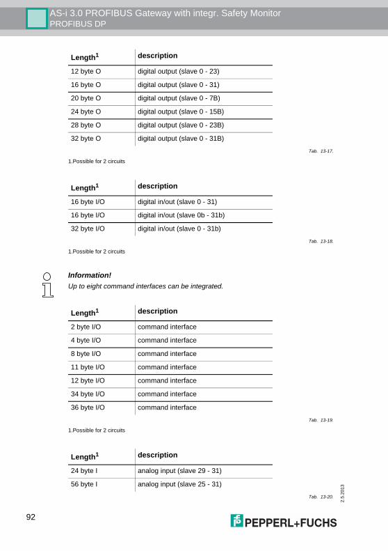
2.5
.201
3
AS-i 3.0 PROFIBUS Gateway with integr. Safety MonitorPROFIBUS DP
12 byte O digital output (slave 0 - 23)
16 byte O digital output (slave 0 - 31)
20 byte O digital output (slave 0 - 7B)
24 byte O digital output (slave 0 - 15B)
28 byte O digital output (slave 0 - 23B)
32 byte O digital output (slave 0 - 31B)
1.Possible for 2 circuits
Length1 description
16 byte I/O digital in/out (slave 0 - 31)
16 byte I/O digital in/out (slave 0b - 31b)
32 byte I/O digital in/out (slave 0 - 31b)
Tab. 13-18.
1.Possible for 2 circuits
Length1 description
Tab. 13-17.
Information!Up to eight command interfaces can be integrated.
Length1 description
2 byte I/O command interface
4 byte I/O command interface
8 byte I/O command interface
11 byte I/O command interface
12 byte I/O command interface
34 byte I/O command interface
36 byte I/O command interface
Tab. 13-19.
1.Possible for 2 circuits
Length1 description
24 byte I analog input (slave 29 - 31)
56 byte I analog input (slave 25 - 31)
Tab. 13-20.
92
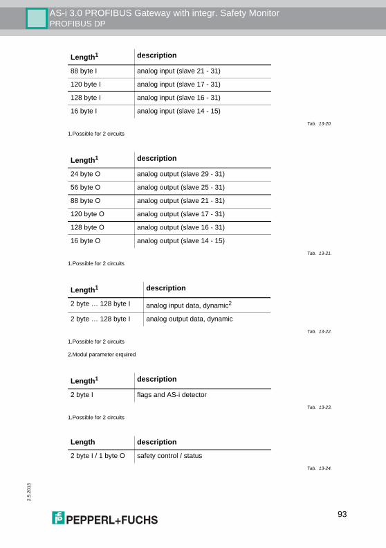
AS-i 3.0 PROFIBUS Gateway with integr. Safety MonitorPROFIBUS DP
2.5.
2013
88 byte I analog input (slave 21 - 31)
120 byte I analog input (slave 17 - 31)
128 byte I analog input (slave 16 - 31)
16 byte I analog input (slave 14 - 15)
1.Possible for 2 circuits
Length1 description
24 byte O analog output (slave 29 - 31)
56 byte O analog output (slave 25 - 31)
88 byte O analog output (slave 21 - 31)
120 byte O analog output (slave 17 - 31)
128 byte O analog output (slave 16 - 31)
16 byte O analog output (slave 14 - 15)
Tab. 13-21.
1.Possible for 2 circuits
Length1 description
2 byte … 128 byte I analog input data, dynamic2
2 byte … 128 byte I analog output data, dynamic
Tab. 13-22.
1.Possible for 2 circuits
2.Modul parameter erquired
Length1 description
2 byte I flags and AS-i detector
Tab. 13-23.
1.Possible for 2 circuits
Length description
2 byte I / 1 byte O safety control / status
Tab. 13-24.
Length1 description
Tab. 13-20.
93
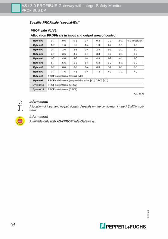
2.5
.201
3
AS-i 3.0 PROFIBUS Gateway with integr. Safety MonitorPROFIBUS DP
Spezific PROFIsafe "special-IDs"
PROFIsafe V1/V2Allocation PROFIsafe in input and output area of control
Byte n+0 0-7 0-6 0-5 0-4 0-3 0-2 0-1 0-0 (reserviert)
Byte n+1 1-7 1-6 1-5 1-4 1-3 1-2 1-1 1-0
Byte n+2 2-7 2-6 2-5 2-4 2-3 2-2 2-1 2-0
Byte n+3 3-7 3-6 3-5 3-4 3-3 3-2 3-1 3-0
Byte n+4 4-7 4-6 4-5 4-4 4-3 4-2 4-1 4-0
Byte n+5 5-7 5-6 5-5 5-4 5-3 5-2 5-1 5-0
Byte n+6 6-7 6-6 6-5 6-4 6-3 6-2 6-1 6-0
Byte n+7 7-7 7-6 7-5 7-4 7-3 7-2 7-1 7-0
Byte n+8 PROFIsafe internal (control byte)
Byte n+9 PROFIsafe internal (sequential number [V1], CRC2 [V2])
Byte n+10 PROFIsafe internal (CRC2)
Byte n+11 PROFIsafe internal (CRC2)
Tab. 13-25.
Information!Allocation of input and output signals depends on the configarion in the ASIMON soft-ware.
Information!Available only with AS-i/PROFIsafe Gateways.
94
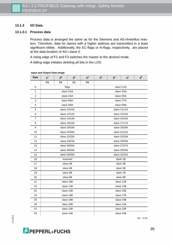
AS-i 3.0 PROFIBUS Gateway with integr. Safety MonitorPROFIBUS DP
2.5.
2013
13.1.3 I/O Data
13.1.3.1 Process data
Process data is arranged the same as for the Siemens and AS-i/InterBus mas-ters. Therefore, data for slaves with a higher address are transmitted in a leastsignificant nibble. Additionally, the EC-flags or hi-flags, respectively, are placedat the data location of AS-i slave 0.A rising edge of F2 and F3 switches the master to the desired mode.A falling edge initiates deleting all bits in the LOS.
Input and Output Data Image
Byte 27 26 25 24 23 22 21 20
F3 F2 F1 F0
0 flags slave 1/1A
1 slave 2/2A slave 3/3A
2 slave 4/4A slave 5/5A
3 slave 6/6A slave 7/7A
4 slave 8/8A slave 9/9A
5 slave 10/10A slave 11/11A
6 slave 12/12A slave 13/13A
7 slave 14/14A slave 15/15A
8 slave 16/16A slave 17/17A
9 slave 18/18A slave 19/19A
10 slave 20/20A slave 21/21A
11 slave 22/22A slave 23/23A
12 slave 24/24A slave 25/25A
13 slave 26/26A slave 27/27A
14 slave 28/28A slave 29/29A
15 slave 30/30A slave 31/31A
16 reserved slave 1B
17 slave 2B slave 3B
18 slave 4B slave 5B
19 slave 6B slave 7B
20 slave 8B slave 9B
21 slave 10B slave 11B
22 slave 12B slave 13B
23 slave 14B slave 15B
24 slave 16B slave 17B
25 slave 18B slave 19B
26 slave 20B slave 21B
27 slave 22B slave 23B
28 slave 24B slave 25B
Tab. 13-26.
95
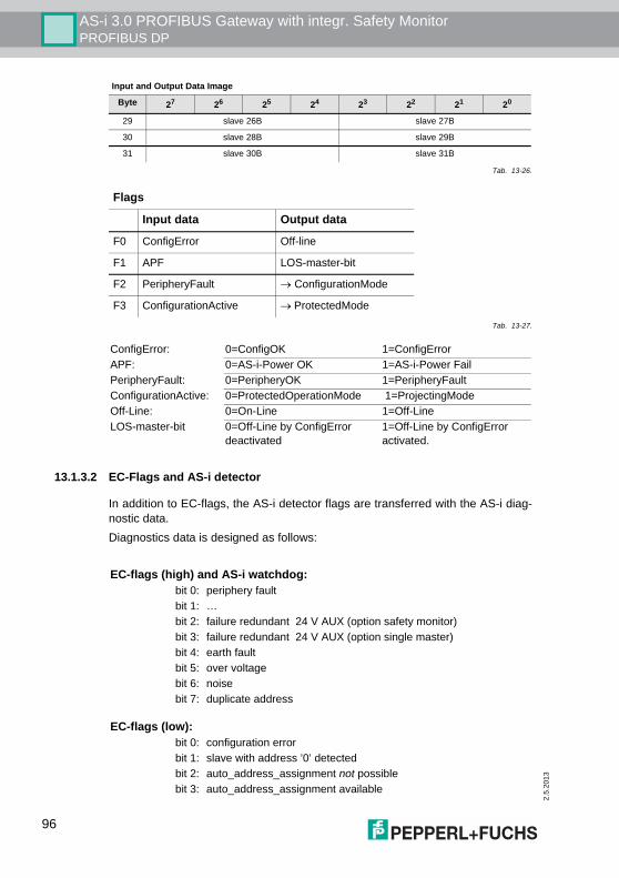
2.5
.201
3
AS-i 3.0 PROFIBUS Gateway with integr. Safety MonitorPROFIBUS DP
13.1.3.2 EC-Flags and AS-i detector
In addition to EC-flags, the AS-i detector flags are transferred with the AS-i diag-nostic data.Diagnostics data is designed as follows:
29 slave 26B slave 27B
30 slave 28B slave 29B
31 slave 30B slave 31B
Flags
Input data Output data
F0 ConfigError Off-line
F1 APF LOS-master-bit
F2 PeripheryFault → ConfigurationMode
F3 ConfigurationActive → ProtectedMode
Tab. 13-27.
ConfigError: 0=ConfigOK 1=ConfigErrorAPF: 0=AS-i-Power OK 1=AS-i-Power FailPeripheryFault: 0=PeripheryOK 1=PeripheryFaultConfigurationActive: 0=ProtectedOperationMode 1=ProjectingModeOff-Line: 0=On-Line 1=Off-LineLOS-master-bit 0=Off-Line by ConfigError
deactivated1=Off-Line by ConfigError activated.
Input and Output Data Image
Byte 27 26 25 24 23 22 21 20
Tab. 13-26.
EC-flags (high) and AS-i watchdog:bit 0: periphery faultbit 1: …bit 2: failure redundant 24 V AUX (option safety monitor)bit 3: failure redundant 24 V AUX (option single master)bit 4: earth faultbit 5: over voltagebit 6: noisebit 7: duplicate address
EC-flags (low):bit 0: configuration errorbit 1: slave with address ’0’ detectedbit 2: auto_address_assignment not possiblebit 3: auto_address_assignment available
96
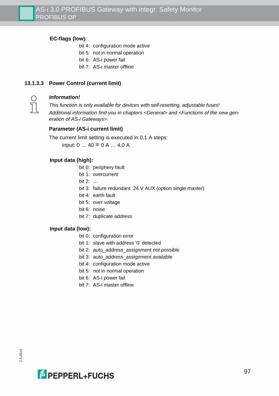
AS-i 3.0 PROFIBUS Gateway with integr. Safety MonitorPROFIBUS DP
2.5.
2013
13.1.3.3 Power Control (current limit)
Parameter (AS-i current limit)The current limit setting is executed in 0,1 A steps:
input: 0 … 40 ! 0 A … 4,0 A
bit 4: configuration mode activebit 5: not in normal operationbit 6: AS-i power failbit 7: AS-i master offline
EC-flags (low):
Information!This function is only available for devices with self-resetting, adjustable fuses!Additional information find you in chapters <General> and <Functions of the new gen-eration of AS-i Gateways>.
Input data (high):bit 0: periphery faultbit 1: overcurrentbit 2: …bit 3: failure redundant 24 V AUX (option single master)bit 4: earth faultbit 5: over voltagebit 6: noisebit 7: duplicate address
Input data (low):bit 0: configuration errorbit 1: slave with address ’0’ detectedbit 2: auto_address_assignment not possiblebit 3: auto_address_assignment availablebit 4: configuration mode activebit 5: not in normal operationbit 6: AS-i power failbit 7: AS-i master offline
97
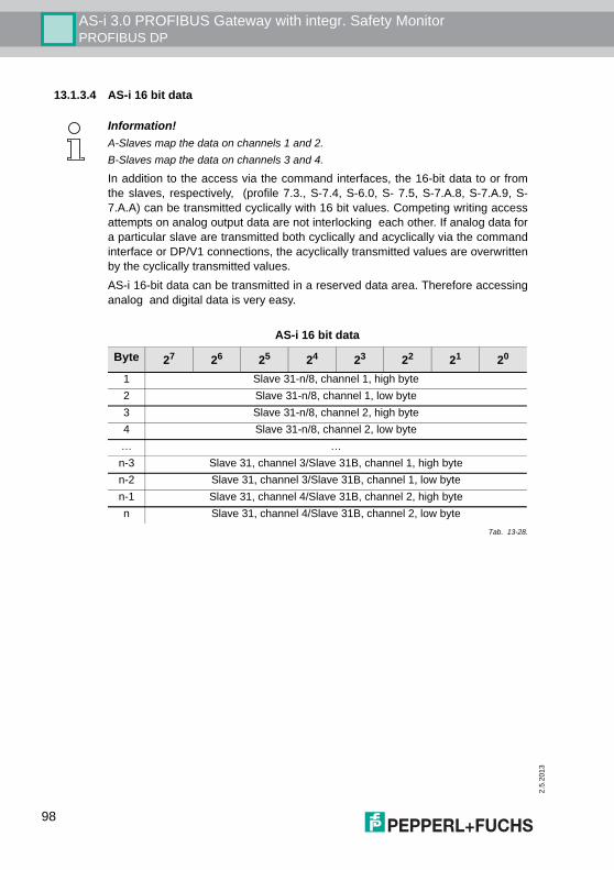
2.5
.201
3
AS-i 3.0 PROFIBUS Gateway with integr. Safety MonitorPROFIBUS DP
13.1.3.4 AS-i 16 bit data
In addition to the access via the command interfaces, the 16-bit data to or fromthe slaves, respectively, (profile 7.3., S-7.4, S-6.0, S- 7.5, S-7.A.8, S-7.A.9, S-7.A.A) can be transmitted cyclically with 16 bit values. Competing writing accessattempts on analog output data are not interlocking each other. If analog data fora particular slave are transmitted both cyclically and acyclically via the commandinterface or DP/V1 connections, the acyclically transmitted values are overwrittenby the cyclically transmitted values.AS-i 16-bit data can be transmitted in a reserved data area. Therefore accessinganalog and digital data is very easy.
Information!A-Slaves map the data on channels 1 and 2.B-Slaves map the data on channels 3 and 4.
AS-i 16 bit data
Byte 27 26 25 24 23 22 21 20
1 Slave 31-n/8, channel 1, high byte2 Slave 31-n/8, channel 1, low byte3 Slave 31-n/8, channel 2, high byte4 Slave 31-n/8, channel 2, low byte… …n-3 Slave 31, channel 3/Slave 31B, channel 1, high byten-2 Slave 31, channel 3/Slave 31B, channel 1, low byten-1 Slave 31, channel 4/Slave 31B, channel 2, high byten Slave 31, channel 4/Slave 31B, channel 2, low byte
Tab. 13-28.
98

AS-i 3.0 PROFIBUS Gateway with integr. Safety MonitorPROFIBUS DP
2.5.
2013
13.1.3.5 Command interface
13.1.3.6 Safety Control/Status
In the fieldbus configuration the designator Safety Control/Status can be addedas cyclical data. This is possible both for the integrated Safety Monitor and for 2ndgeneration Monitors.
The state of the outputs and the message outputs is then inserted as a cyclical in-put datum.
Information!The description of the ASIMON program can be found in the separate software manual„AS-i 3.0 Command interface“.
Information!Generation III external Monitors allow a maximum of eight OSSDs to be sent.
Inputsbyte description1 Status OSSD 1, color-coded as defined in the table <Coding of status bytes>).
2 Status OSSD 2, color-coded as defined in the table <Coding of status bytes>).
… …
n Status OSSD n, color-coded as defined in the table <Coding of status bytes>).
Tab. 13-29.
Coding of status bytes
Bit [0 ... 3] state or. color description
0016 green permanent lighting output on
0116 green flashing delay time is running at stop category 1
0216 yellow permanent lighting start-up/restart-disable active
0316 yellow flashing external test necessary / acknowledgement / start delay active
0416 red permanent lighting output off
0516 red flashing error
0616 grey or off output not projected
0716 reserved
Bit [6] status or color Tab. 13-30.
99
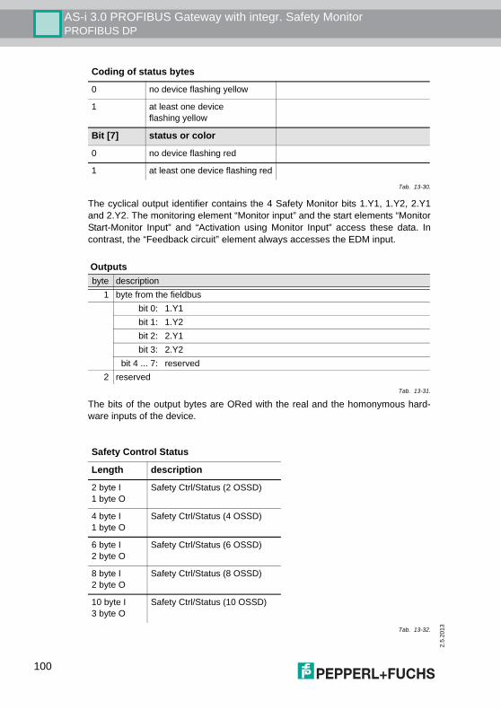
2.5
.201
3
AS-i 3.0 PROFIBUS Gateway with integr. Safety MonitorPROFIBUS DP
The cyclical output identifier contains the 4 Safety Monitor bits 1.Y1, 1.Y2, 2.Y1and 2.Y2. The monitoring element “Monitor input” and the start elements “MonitorStart-Monitor Input” and “Activation using Monitor Input” access these data. Incontrast, the “Feedback circuit” element always accesses the EDM input.
The bits of the output bytes are ORed with the real and the homonymous hard-ware inputs of the device.
0 no device flashing yellow
1 at least one device flashing yellow
Bit [7] status or color
0 no device flashing red
1 at least one device flashing red
Outputsbyte description
1 byte from the fieldbusbit 0: 1.Y1bit 1: 1.Y2bit 2: 2.Y1bit 3: 2.Y2
bit 4 ... 7: reserved2 reserved
Tab. 13-31.
Safety Control Status
Length description
2 byte I1 byte O
Safety Ctrl/Status (2 OSSD)
4 byte I1 byte O
Safety Ctrl/Status (4 OSSD)
6 byte I2 byte O
Safety Ctrl/Status (6 OSSD)
8 byte I2 byte O
Safety Ctrl/Status (8 OSSD)
10 byte I3 byte O
Safety Ctrl/Status (10 OSSD)
Tab. 13-32.
Coding of status bytes
Tab. 13-30.
100
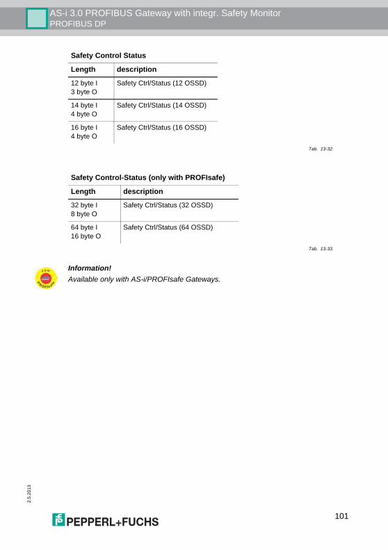
AS-i 3.0 PROFIBUS Gateway with integr. Safety MonitorPROFIBUS DP
2.5.
2013
12 byte I3 byte O
Safety Ctrl/Status (12 OSSD)
14 byte I4 byte O
Safety Ctrl/Status (14 OSSD)
16 byte I4 byte O
Safety Ctrl/Status (16 OSSD)
Safety Control-Status (only with PROFIsafe)
Length description
32 byte I8 byte O
Safety Ctrl/Status (32 OSSD)
64 byte I16 byte O
Safety Ctrl/Status (64 OSSD)
Tab. 13-33.
Safety Control Status
Length description
Tab. 13-32.
Information!Available only with AS-i/PROFIsafe Gateways.
101
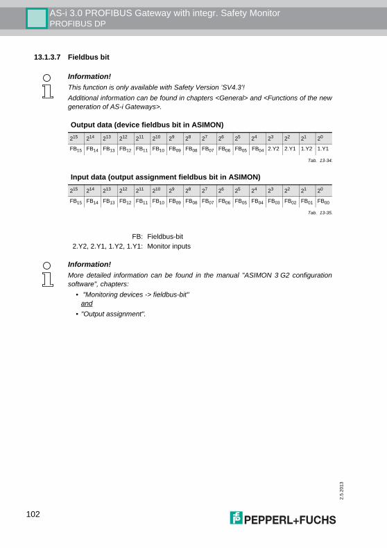
2.5
.201
3
AS-i 3.0 PROFIBUS Gateway with integr. Safety MonitorPROFIBUS DP
13.1.3.7 Fieldbus bit
Information!This function is only available with Safety Version ’SV4.3’!Additional information can be found in chapters <General> and <Functions of the newgeneration of AS-i Gateways>.
Output data (device fieldbus bit in ASIMON)
215 214 213 212 211 210 29 28 27 26 25 24 23 22 21 20
FB15 FB14 FB13 FB12 FB11 FB10 FB09 FB08 FB07 FB06 FB05 FB04 2.Y2 2.Y1 1.Y2 1.Y1
Tab. 13-34.
Input data (output assignment fieldbus bit in ASIMON)
215 214 213 212 211 210 29 28 27 26 25 24 23 22 21 20
FB15 FB14 FB13 FB12 FB11 FB10 FB09 FB08 FB07 FB06 FB05 FB04 FB03 FB02 FB01 FB00
Tab. 13-35.
FB: Fieldbus-bit2.Y2, 2.Y1, 1.Y2, 1.Y1: Monitor inputs
Information!More detailed information can be found in the manual "ASIMON 3 G2 configurationsoftware", chapters:
• "Monitoring devices -> fieldbus-bit"and
• "Output assignment".
102
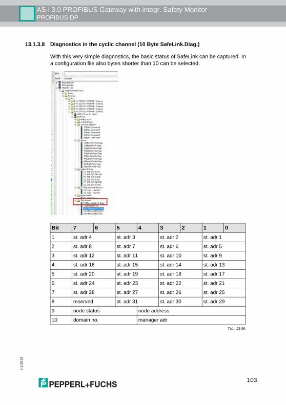
AS-i 3.0 PROFIBUS Gateway with integr. Safety MonitorPROFIBUS DP
2.5.
2013
13.1.3.8 Diagnostics in the cyclic channel (10 Byte SafeLink.Diag.)
With this very simple diagnostics, the basic status of SafeLink can be captured. Ina configuration file also bytes shorter than 10 can be selected.
Example: ’10 Byte SafeLink.Diag’ in a configuration file
Bit 7 6 5 4 3 2 1 01 st. adr 4 st. adr 3 st. adr 2 st. adr 1
2 st. adr 8 st. adr 7 st. adr 6 st. adr 5
3 st. adr 12 st. adr 11 st. adr 10 st. adr 9
4 st. adr 16 st. adr 15 st. adr 14 st. adr 13
5 st. adr 20 st. adr 19 st. adr 18 st. adr 17
6 st. adr 24 st. adr 23 st. adr 22 st. adr 21
7 st. adr 28 st. adr 27 st. adr 26 st. adr 25
8 reserved st. adr 31 st. adr 30 st. adr 29
9 node status node address
10 domain no. manager adr Tab. 13-36.
103
2.5
.201
3
AS-i 3.0 PROFIBUS Gateway with integr. Safety MonitorPROFIBUS DP
13.2 DP/V1The AS-i 3.0 PROFIBUS Gateway with integr. Safety Monitor uses only one datasegment (slot 1, index 16). This data segment contains a command interface sim-ilar to the one in the DP data telegram.The DP/V1-command interfaces are processed every time they are sent. There-fore it is possible to execute the same command several times without changing"command" or "network" and setting a toggle bit.
13.3 PROFIBUSThe AS-i 3.0 PROFIBUS Gateway with integr. Safety Monitor uses a new GSDfile with a new PNO-ID. All the setting options for the previous AS-i Masters areavailable. Cyclical data, Command interface and (optional) diagnostics are com-patible with the previous Master.
St. adr: status of an address from the list ’node overview’:
bit-combination meaning11 active
01 not active
10 nicht taught (only the manager, with the highest priority message)
00 not used
Information!GSD files for the previous AS-i Masters cannot be used, since the PROFIBUS parame-ters have a different structure.
104

AS-i 3.0 PROFIBUS Gateway with integr. Safety MonitorConfiguration with Windows Software ASIMON 3 G2
2.5.
2013
105
14. Configuration with Windows Software ASIMON 3 G2
Information!Please note further information in the configuration software ASIMON 3 G2 for Win-dows.
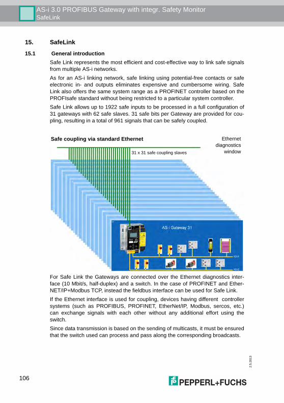
2.5
.201
3
AS-i 3.0 PROFIBUS Gateway with integr. Safety MonitorSafeLink
15. SafeLink
15.1 General introductionSafe Link represents the most efficient and cost-effective way to link safe signalsfrom multiple AS-i networks. As for an AS-i linking network, safe linking using potential-free contacts or safeelectronic in- and outputs eliminates expensive and cumbersome wiring. SafeLink also offers the same system range as a PROFINET controller based on thePROFIsafe standard without being restricted to a particular system controller.Safe Link allows up to 1922 safe inputs to be processed in a full configuration of31 gateways with 62 safe slaves. 31 safe bits per Gateway are provided for cou-pling, resulting in a total of 961 signals that can be safely coupled.
For Safe Link the Gateways are connected over the Ethernet diagnostics inter-face (10 Mbit/s, half-duplex) and a switch. In the case of PROFINET and Ether-NET/IP+Modbus TCP, instead the fieldbus interface can be used for Safe Link.If the Ethernet interface is used for coupling, devices having different controllersystems (such as PROFIBUS, PROFINET, EtherNet/IP, Modbus, sercos, etc.)can exchange signals with each other without any additional effort using theswitch.Since data transmission is based on the sending of multicasts, it must be ensuredthat the switch used can process and pass along the corresponding broadcasts.
Ethernetdiagnostics
window
Safe coupling via standard Ethernet
31 x 31 safe coupling slaves
106
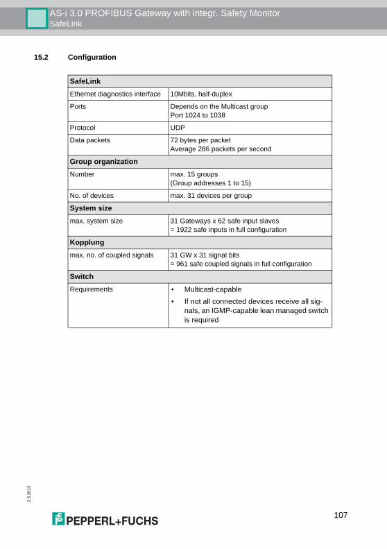
AS-i 3.0 PROFIBUS Gateway with integr. Safety MonitorSafeLink
2.5.
2013
15.2 Configuration
SafeLinkEthernet diagnostics interface 10Mbits, half-duplex
Ports Depends on the Multicast groupPort 1024 to 1038
Protocol UDP
Data packets 72 bytes per packetAverage 286 packets per second
Group organizationNumber max. 15 groups
(Group addresses 1 to 15)
No. of devices max. 31 devices per group
System sizemax. system size 31 Gateways x 62 safe input slaves
= 1922 safe inputs in full configuration
Kopplungmax. no. of coupled signals 31 GW x 31 signal bits
= 961 safe coupled signals in full configuration
SwitchRequirements • Multicast-capable
• If not all connected devices receive all sig-nals, an IGMP-capable lean managed switch is required
107
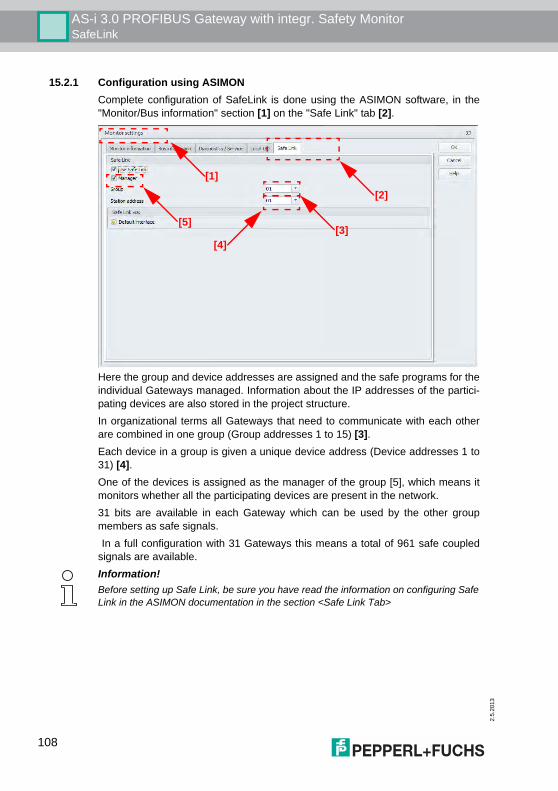
2.5
.201
3
AS-i 3.0 PROFIBUS Gateway with integr. Safety MonitorSafeLink
15.2.1 Configuration using ASIMONComplete configuration of SafeLink is done using the ASIMON software, in the"Monitor/Bus information" section [1] on the "Safe Link" tab [2].
Here the group and device addresses are assigned and the safe programs for theindividual Gateways managed. Information about the IP addresses of the partici-pating devices are also stored in the project structure.In organizational terms all Gateways that need to communicate with each otherare combined in one group (Group addresses 1 to 15) [3].Each device in a group is given a unique device address (Device addresses 1 to31) [4]. One of the devices is assigned as the manager of the group [5], which means itmonitors whether all the participating devices are present in the network.31 bits are available in each Gateway which can be used by the other groupmembers as safe signals. In a full configuration with 31 Gateways this means a total of 961 safe coupledsignals are available.
[1]
[2]
[3][4]
[5]
Information!Before setting up Safe Link, be sure you have read the information on configuring SafeLink in the ASIMON documentation in the section <Safe Link Tab>
108
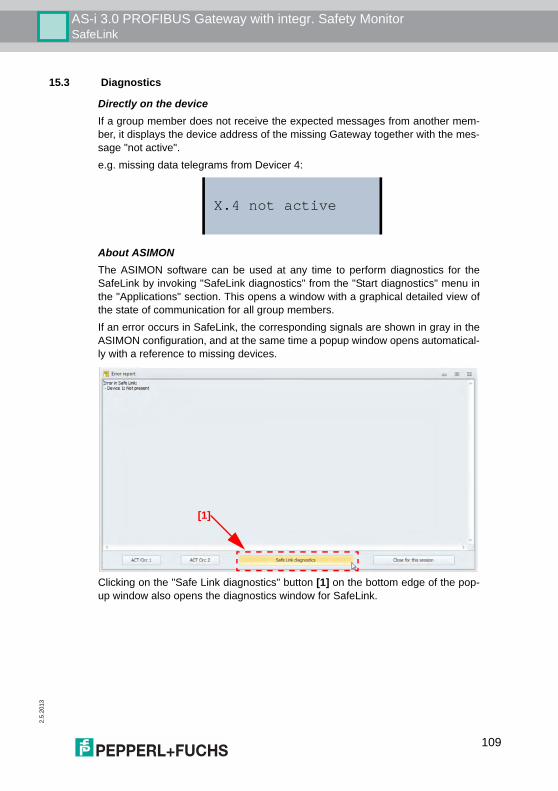
AS-i 3.0 PROFIBUS Gateway with integr. Safety MonitorSafeLink
2.5.
2013
15.3 Diagnostics
Directly on the deviceIf a group member does not receive the expected messages from another mem-ber, it displays the device address of the missing Gateway together with the mes-sage "not active".e.g. missing data telegrams from Devicer 4:
About ASIMONThe ASIMON software can be used at any time to perform diagnostics for theSafeLink by invoking "SafeLink diagnostics" from the "Start diagnostics" menu inthe "Applications" section. This opens a window with a graphical detailed view ofthe state of communication for all group members.If an error occurs in SafeLink, the corresponding signals are shown in gray in theASIMON configuration, and at the same time a popup window opens automatical-ly with a reference to missing devices.
Clicking on the "Safe Link diagnostics" button [1] on the bottom edge of the pop-up window also opens the diagnostics window for SafeLink.
X.4 not active
[1]
109
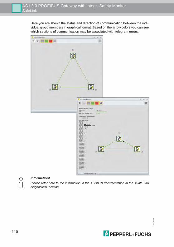
2.5
.201
3
AS-i 3.0 PROFIBUS Gateway with integr. Safety MonitorSafeLink
Here you are shown the status and direction of communication between the indi-vidual group members in graphical format. Based on the arrow colors you can see which sections of communication may be associated with telegram errors.
Information!Please refer here to the information in the ASIMON documentation in the <Safe Linkdiagnostics> section.
110

AS-i 3.0 PROFIBUS Gateway with integr. Safety MonitorSystem startup using AS-i Control Tools
2.5.
2013
16. System startup using AS-i Control Tools
The Windows based software "AS-i Control Tools" with a serial interface for stain-less steel AS-i masters is designed to make the startup of the AS-i 3.0 PROFI-BUS Gateway with integr. Safety Monitor as comfortable as possible.Additionally, the software communicates with the AS-i 3.0 PROFIBUS Gatewaywith integr. Safety Monitor by using a PROFIBUS DP Master Simulator DP/V1 orthe serial PROFIBUS master.
16.1 Windows software AS-i Control Tools
This way, the device driver is copied into the previous designed folder in AS-iControl Tools and should be recognized automatically.The Windows software "AS-i Control Tools" enables the user to easily configurethe AS-i network. 1. Plug the PROFIBUS Master Simulator or a serial PROFIBUS Master,
respectively, into the D-SUB connector of the AS-i/PROFIBUS Gatewayand connect the device to the PC via its serial interface.
2. Start AS-i Control Tools.3. Select Master | New.
4. Choose PROFIBUS as the protocol.5. Select the appropriate settings (for example serial interface COM 2, station
address <auto>).
Information!AS-i Control Tools must be installed first!
111
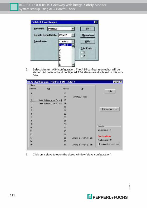
2.5
.201
3
AS-i 3.0 PROFIBUS Gateway with integr. Safety MonitorSystem startup using AS-i Control Tools
6. Select Master | AS-i configuration. The AS-i configuration editor will be started. All detected and configured AS-i slaves are displayed in this win-dow.
7. Click on a slave to open the dialog window 'slave configuration'.
112
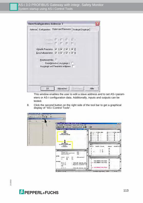
AS-i 3.0 PROFIBUS Gateway with integr. Safety MonitorSystem startup using AS-i Control Tools
2.5.
2013
This window enables the user to edit a slave address and to set AS-i param-eters or AS-i configuration data. Additionally, inputs and outputs can be tested.
8. Click the second button on the right side of the tool bar to get a graphical display of "AS-i Control Tools".
113

2.5
.201
3
AS-i 3.0 PROFIBUS Gateway with integr. Safety MonitorSystem startup using AS-i Control Tools
Configuring the AS-i network is easily accomplished by first connecting each AS-islave separately to the AS-i line and setting its address, followed by pressing thebutton “Store configuration” to store the existing AS-i network in the AS-i masteras configuration data.Furthermore, an AS-i Address Assistant is available, allowing to perform an ad-dress change of a new AS-i slave to the desired address as soon as it is connect-ed to the AS-i network. The desired AS-i configuration can be created offlineahead of time and can be stored to a file. When setting up the system the AS-islaves are then simply connected, one at a time, to the AS-i network. Further de-scriptions to all additional features of this software can be obtained from the inte-grated help file.
16.2 PROFIBUS DP Master Simulator
The PROFIBUS DP Master Simulator is an easy to use universal tool for data ex-change with PROFIBUS slaves from almost any manufacturer using PROFIBUSDP. The PROFIBUS DP master simulator can exchange data with many PROFI-BUS slaves even without GSD file, type-file, or PROFIBUS master. Furthermore,the PROFIBUS DP Master Simulator also processes GSD-files as well as the in-put of special configurations to start the data exchange with the PROFIBUSslaves.. Addressing of PROFIBUS slaves - especially IP67 modules without ad-dressing switch - is also possible.The PROFIBUS DP Master Simulator also offers the possibility to scan a com-plete PROFIBUS network for connected users and to display them graphically. Inthis case, the PROFIBUS UART has to be connected directly to a PROFIBUSslave. I/O data, especially diagnostics data, can now be displayed in binary, hexa-decimal, and ASCII format. The output data can be transmitted consistently. It ispossible to hold an output as long as the mouse button is pressed in "click andhold" mode. The new version of the PROFIBUS DP Master Simulator also supports PROFI-BUS DP/V1, and therefore enables PROFIBUS slaves to be operated in the acy-clic mode. This is especially helpful for the configuration and the startup of com-plex field devices like drives, modular I/O systems, etc.The PROFIBUS Master Simulator is delivered with the PROFIBUS UART, theideal interface converter between the RS 232 interface of a PC and PROFIBUS.The compact UART does not need an additional external power supply.Therefore it is also suitable for mobile use with a laptop or a notebook. ThePROFIBUS UART is simply inserted between the PROFIBUS and the RS 232connector cable. Additionally to the monitor and startup software DLL drivers for Windows NT,2000, XP, Vista as well as simple examples written in C are supplied with thePROFIBUS UART. This offers the possibility to use the PROFIBUS UART in com-bination with other software applications. However, the PROFI-BUS UART is amonitoring and startup tool for PROFIBUS slaves and is not designed to controlautomation processes.
114
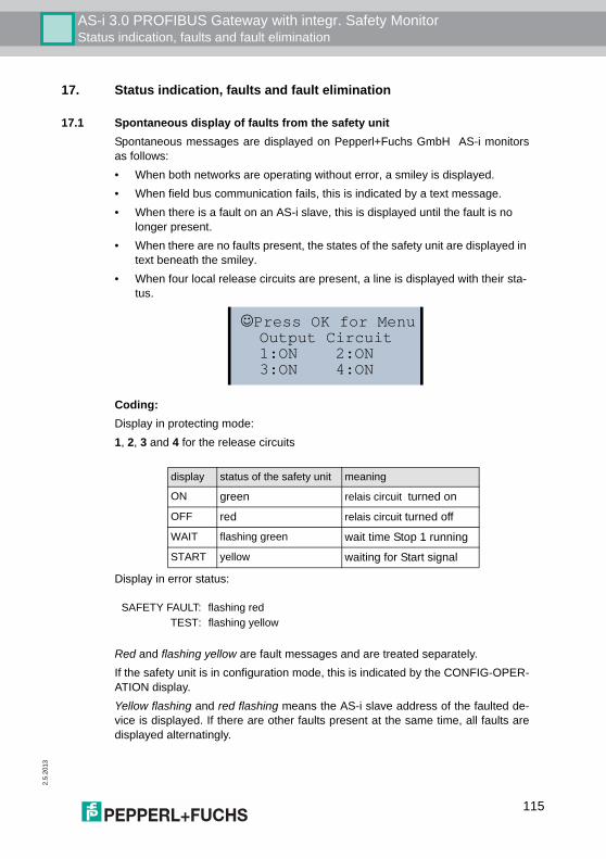
AS-i 3.0 PROFIBUS Gateway with integr. Safety MonitorStatus indication, faults and fault elimination
2.5.
2013
17. Status indication, faults and fault elimination
17.1 Spontaneous display of faults from the safety unitSpontaneous messages are displayed on Pepperl+Fuchs GmbH AS-i monitorsas follows:• When both networks are operating without error, a smiley is displayed.• When field bus communication fails, this is indicated by a text message.• When there is a fault on an AS-i slave, this is displayed until the fault is no
longer present.• When there are no faults present, the states of the safety unit are displayed in
text beneath the smiley.• When four local release circuits are present, a line is displayed with their sta-
tus.
Coding:Display in protecting mode:1, 2, 3 and 4 for the release circuits
Display in error status:
Red and flashing yellow are fault messages and are treated separately.If the safety unit is in configuration mode, this is indicated by the CONFIG-OPER-ATION display.Yellow flashing and red flashing means the AS-i slave address of the faulted de-vice is displayed. If there are other faults present at the same time, all faults aredisplayed alternatingly.
☺Press OK for Menu Output Circuit 1:ON 2:ON 3:ON 4:ON
display status of the safety unit meaning
ON green relais circuit turned on
OFF red relais circuit turned off
WAIT flashing green wait time Stop 1 running
START yellow waiting for Start signal
SAFETY FAULT: flashing redTEST: flashing yellow
115

2.5
.201
3
AS-i 3.0 PROFIBUS Gateway with integr. Safety MonitorStatus indication, faults and fault elimination
If the safety unit is in the red flashing state and no menu is open, the safety unitcan be unlocked by pressing the ESC/Service key (Section <Function of the ESC/Service key>).• If the message “Fatal Error” is reported from the safety unit, only this error
message will be displayed in normal mode (not the menu). The non-safe unit continues to operate normally in this case and the menus can also be opened.
• All other messages are not shown spontaneously.If the safety unit is in the yellow flashing state, depending on the status of the con-figuration an external test may be required, an acknowledgement of the statusmay need to be made, or the turn-on delay active.
17.2 Replacing a defective safety-configured AS-i slaveIf a safety-configured AS-i slave is defective, it can be replaced even without a PCor reconfiguration of the AS-i Safety Monitor by pressing the ESC/Service key onthe AS-i Safety Monitor.
Proceed as follows:1. Disconnect the AS-i slave from the AS-i cable.2. Press the ESC/Service key on the AS-i Safety Monitor and on all other
safety monitors for approx. 3 seconds.
3. Connect the new safety-configured AS-i slave, which has already been pro-grammed to the corresponding address, to the AS-i cable.
4. Press the ESC/Service key again on the AS-i Safety Monitor and on all other Safety Monitors which use the replacement safe AS-i slave for approx. 3 seconds. The code table for the new slave is taught and checked for cor-rectness. If this is OK, the AS-i Safety Monitor changes to protecting mode. Otherwise you are prompted again to teach.
FATAL ERROR000 255 222 111
Information!Pressing the ESC/Service key changes the safety monitor from protecting mode toconfiguration mode. The output circuits are therefore not turned off. Code tables for replaced AS-i slaves can be taught without the PIN.
CONNECT NEWSLAVE 17THEN PRESSSERVICE
Information!Inputs on the new slave must be turned on.
116
AS-i 3.0 PROFIBUS Gateway with integr. Safety MonitorStatus indication, faults and fault elimination
2.5.
2013
17.3 Replacing a defective AS-i Safety MonitorIf an AS-i Safety Monitor is defective and needs to be replaced, the replacementunit does not necessarily have to be newly configured using the ASIMON 3 G2software, rather it is possible to copy the configuration of the defective device us-ing a chip card. Requirement:The replacement unit has an empty configuration in its configuration memory.
17.4 Forget the password? What do I do now?
If the password is lost for your configuration, proceed as follows:1. Find the valid configuration protocol for the AS-i Safety Monitor whose pass-
word you have lost (printout or file). In the configuration protocol in line 10(Monitor Section, Validated) you will find a 4-digit code.
• If you do not have the configuration protocol and do not want to place the AS-i safety monitor in configuration mode, connect the AS-i safety monitor whose password you have lost to the PC and start the ASIMON 3 G2 software.
• Select a neutral configuration and start the diagnostics function in ASIMON 3 G2 using MONITOR -> DIAGNOSTICS. Wait until the current configuration appears on the screen. This may take up to 1 minute.
• Open the window MONITOR/BUS INFORMATION (EDIT MENU -> MONI-TOR/BUS INFORMATION…). On the Title tab you will also find the 4-digit code in the Download time window area.
2. Contact technical support at your supplier and enter the 4-digit code. 3. From this code a master password can be generated which can be used to
access the stored configuration.4. Use this master password to stop the AS-i Safety Monitor and enter a new
user password. In the Monitor menu of the ASIMON 3 G2 configuration soft-ware select the menu item Password changing.
Attention!After replacing a defective safe AS-i slave, always check the correct function ofthe new slave.
Information!After replacing a defective safe AS-i Safety Monitor, always check the correct functionof the new AS-i Safety Monitor.
Attention!Only the responsible safety representative is permitted to retrieve a lost passwordas follows!
Attention!Please note that accessing the configuration stored in the AS-i Safety Monitorcan affect the safe function of the system. Changes to released configurationsare to be made only by authorized personnel. Any change must be made accor-ding to the instructions in the User's Manual for the ASIMON 3 G2 configurationsoftware.
117

2.5
.201
3
AS-i 3.0 PROFIBUS Gateway with integr. Safety MonitorStatus indication, faults and fault elimination
Information!The default password (factory setting) of the AS-i safety monitor is "SIMON". If youwould like to reconfigure the AS-i safety monitor, you must first change this defaultpassword to a new one known only to you as safety officer.
118
AS-i 3.0 PROFIBUS Gateway with integr. Safety MonitorGlossary
2.5.
2013
18. Glossary
A/B slaveAn AS-i slave with extended addressing. The address range of an A/B slave ex-tends from 1A to 31A and 1B to 31B.
AS-i Power FailVoltage drop on the AS-i line; If the voltage drops below a specific value, the mas-ter changes to the ⇒ Offline phase.
I/O codeThe first digit of the slave profile, which indicates how many in- and outputs theslave has. A 4I/4O slave has for example a “7”, and a slave with 4 digital inputs a"0".
EDM (External Device Monitoring, feedback circuit)Used for monitoring the switching function of the contactors connected to theSafety Monitor, whereby the normally closed contacts (forced-opening when pos-sible) are fed back to the start circuit of the Safety Monitor. A restart is then onlypossible if the normally closed contacts are closed (in the quiescent state).
Detection phaseIn the detection phase, after the startup the master is scanning for AS-i slaves.The master remains in this phase until at least one slave was detected. If themaster remains in the detection phase no slave was found. Most of the time, thereason for this is a wrong power supply or a wiring error.The detection phase is indicated by code "41".
Protected modeIn protected operating mode only those slaves that are registered in the ⇒ LPSand whose current configuration matches the target configuration are activated.Also see ⇒ configuration mode. This mode is intended for normal operation,since all AS-i protective measures are activated.
ID codeThe ID code is set by the slave manufacturer and cannot be changed. The AS-iAssociation determines the ID codes which are assigned for a particular class ofslaves. For example, all ⇒ A/B slaves have ID code “A“.
ID1 Code, extended ID1 codeThe ID1 code is set by the slave manufacturer. In contrast to the other codes,which determine the profile, it can be changed from the master or using an ad-dressing device. The user should however only use this feature in exceptional cir-cumstances, since otherwise configuration errors may occur.
119
2.5
.201
3
AS-i 3.0 PROFIBUS Gateway with integr. Safety MonitorGlossary
In the case of A/B slaves, the MSB of the ID1 code is used for distinguishing be-tween the A and the B address. Therefore, only the lowest 3 bits are relevant forthese slaves.Since this code was not introduced until AS-i Specification 2.1, it is also referredto as extended ID1 code.
ID2 Code, extended ID2 codeThe ID2 code is set by the slave manufacturer and cannot be changed. The AS-iAssociation determines the ID2 codes, which are assigned for a particular class ofslaves. For example, all 2-channel 16 bit input slaves having an S-7-3 bit codeuse ID2 code “D”. Since this code was not introduced until AS-i Specification 2.1,it is also referred to as extended ID2 code.
Current configuration The configuration data of all slaves detected by the master. The configurationdata of a slave, the ⇒ slave profile, consists of: ⇒ IO code, ⇒ ID code, ⇒ extended ID1code , ⇒ extended ID2 code.
Current parameter The AS-i parameter that have most recently been sent to the AS-i slave, as op-posed to ⇒ permanent parameters.
Configuration Error/Config Error An configuration error is displayed if the target and the current configuration of theconnected slaves do not match. A configuration error could be due to the follow-ing:Missing slave:A slave entered in the ⇒ LPS is not available Wrong type of slave:The ⇒ slave profile of the connected slave does not complywith the configuration.Unknown slave: A connected slave is not entered in the ⇒ LPS.
LAS - List of Activated SlavesThe master exchanges I/O data with the slaves entered in the LAS. In protectedmode only the detected slaves (⇒ LDS) that are expected by the master and areentered in the ⇒ LPS are activated. In configuration mode all slaves entered inthe ⇒ LDS are activated.
LDS - List of Detected SlavesIf the master was able to read the ⇒ slave profile, the slave is entered in the LDS.
LPF - List of Peripheral FaultsThe list of peripheral faults was introduced with specification 2.1. This list includesan entry for each slave that signals a ⇒ peripheral fault.
120

AS-i 3.0 PROFIBUS Gateway with integr. Safety MonitorGlossary
2.5.
2013
LPS - List of Projected SlavesThe list of projected slaves includes all slaves expected by the master. When sav-ing the current configuration all entries in the ⇒ LDS are stored in the LPS (ex-cept for a slave with address 0).
Offline phaseIn the offline phase all input and output data is reset. This phase is entered afterthe startup of the master, after a ⇒ AS-i power fail, and during the transition fromthe ⇒ configuration mode to the ⇒ protected mode.Furthermore, the master can actively be transfered into the offline phase by set-ting the offline flag.During the offline phase, masters with a LED display show code "40".No communication will take place during the offline phase.
OSSD = Output Signal Switching Device, release circuitThe safe AS-i components and functional devices assigned to an output circuit ofthe AS-i safety monitor. They are responsible for releasing the machine elementwhich generates the hazardous movement.
PasswordSecurity code for a (security) configuration, is required for releasing a configura-tion or activating a changed configuration. The password is a string of 4 … 8 al-phanumeric characters. It is stored in the configuration.
Peripheral faultA peripheral fault is indicated by a red flashing LED on the master and on theslave.Depending on the slave type this indicates an overflow, an overload of the sen-sor's power supply, or another fault regarding the periphery of the slave.
PINA security code is required for teaching code sequences. The PIN is a 4-digit dec-imal number.The PIN does not authorize for activating a safety configuration.The PIN is stored in the EEPROM of the unprotected device section as well as inthe unprotected area of the chip card, and is therefore sent to a new device whenthe chip card is replaced. When resetting to factory defaults, the PIN is set to0000.
Permanent configurationThe configuration data of all expected slaves stored in the master (⇒ slave pro-file). If the ⇒ permanent configuration differs from the ⇒ actual configuration, aconfiguration error exists.
121
2.5
.201
3
AS-i 3.0 PROFIBUS Gateway with integr. Safety MonitorGlossary
Permanent parameterThe parameters saved in the master and sent to the slave after startup of themaster during the ⇒ activation phase.
Configuration modeDuring the configuration mode the master exchanges data with all connectedslaves, no matter which of the slaves were configured. Thus, in this mode it ispossible to operate a system without the necessity to configure it before.See also ⇒ protected mode.
Release CodeSecurity code for a safety configuration on the chip card. A 4-character hexadeci-mal number generated by the ASIMON 3 G 2 software. The release code is dis-played before copying a configuration from the memory card to the Monitor andmust be repeated by the operator.This provides a technical safeguard against errors in the unprotected display andkeyboard software.
Single SlaveA single slave can in contrast to a ⇒ A/B slave only be addressed from range 1 to31; the fourth output data bit can be used. All slaves as defined by the older AS-iSpecification 2.0 are single slaves.There are however also single slaves as defined by Specification 2.1, for examplethe new 16 bit slaves.
Slave profileConfiguration data for a slave, consisting of:⇒ I/O configuration and ⇒ ID-Code, as well as ⇒ extended ID1-Code and ⇒ ex-tended ID2-Code.The slave profile is used to distinguish between various slave classes. It is speci-fied by the AS-i Association and set by the slave manufacturer.AS-i 2.0 slaves do not have extended ID1 and ID2 codes. A 2.1 or 3.0 AS-inter-face master enters in this case an “F” for each of the extended ID1 and ID2codes.
Master configurationReleased configuration, without code sequences. The safety unit cannot turn onthe outputs, but as soon as the code sequences are learned, the device is usable.Such a master configuration can for example be used in serial production ma-chine building for loading the safety program, whereby the configuration is creat-ed in the design and the code sequences taught on the physical machine.
122
AS-i 3.0 PROFIBUS Gateway with integr. Safety MonitorGlossary
2.5.
2013
Complete configurationCounterpart to ⇒ master configuration. Release configuration including code se-quences. The device is always usable.
123
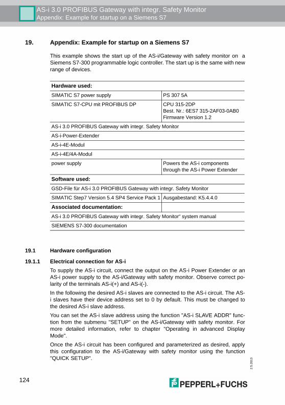
2.5
.201
3
AS-i 3.0 PROFIBUS Gateway with integr. Safety MonitorAppendix: Example for startup on a Siemens S7
19. Appendix: Example for startup on a Siemens S7
This example shows the start up of the AS-i/Gateway with safety monitor on aSiemens S7-300 programmable logic controller. The start up is the same with newrange of devices.
19.1 Hardware configuration
19.1.1 Electrical connection for AS-iTo supply the AS-i circuit, connect the output on the AS-i Power Extender or anAS-i power supply to the AS-i/Gateway with safety monitor. Observe correct po-larity of the terminals AS-i(+) and AS-i(-).In the following the desired AS-i slaves are connected to the AS-i circuit. The AS-i slaves have their device address set to 0 by default. This must be changed tothe desired AS-i slave address.You can set the AS-i slave address using the function "AS-i SLAVE ADDR" func-tion from the submenu "SETUP" on the AS-i/Gateway with safety monitor. Formore detailed information, refer to chapter "Operating in advanced DisplayMode".Once the AS-i circuit has been configured and parameterized as desired, applythis configuration to the AS-i/Gateway with safety monitor using the function"QUICK SETUP".
Hardware used:SIMATIC S7 power supply PS 307 5A
SIMATIC S7-CPU mit PROFIBUS DP CPU 315-2DPBest. Nr.: 6ES7 315-2AF03-0AB0Firmware Version 1.2
AS-i 3.0 PROFIBUS Gateway with integr. Safety Monitor
AS-i-Power-Extender
AS-i-4E-Modul
AS-i-4E/4A-Modul
power supply Powers the AS-i components through the AS-i Power Extender
Software used:GSD-File für AS-i 3.0 PROFIBUS Gateway with integr. Safety Monitor
SIMATIC Step7 Version 5.4 SP4 Service Pack 1 Ausgabestand: K5.4.4.0
Associated documentation:AS-i 3.0 PROFIBUS Gateway with integr. Safety Monitor“ system manual
SIEMENS S7-300 documentation
124
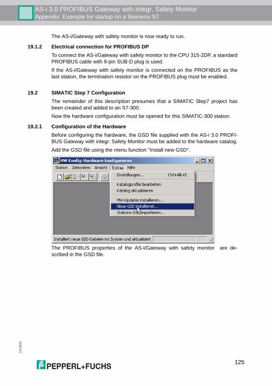
AS-i 3.0 PROFIBUS Gateway with integr. Safety MonitorAppendix: Example for startup on a Siemens S7
2.5.
2013
The AS-i/Gateway with safety monitor is now ready to run.
19.1.2 Electrical connection for PROFIBUS DPTo connect the AS-i/Gateway with safety monitor to the CPU 315-2DP, a standardPROFIBUS cable with 9-pin SUB-D plug is used.If the AS-i/Gateway with safety monitor is connected on the PROFIBUS as thelast station, the termination resistor on the PROFIBUS plug must be enabled.
19.2 SIMATIC Step 7 ConfigurationThe remainder of this description presumes that a SIMATIC Step7 project hasbeen created and added to an S7-300.Now the hardware configuration must be opened for this SIMATIC-300 station.
19.2.1 Configuration of the HardwareBefore configuring the hardware, the GSD file supplied with the AS-i 3.0 PROFI-BUS Gateway with integr. Safety Monitor must be added to the hardware catalog.Add the GSD file using the menu function "Install new GSD".
The PROFIBUS properties of the AS-i/Gateway with safety monitor are de-scribed in the GSD file.
125
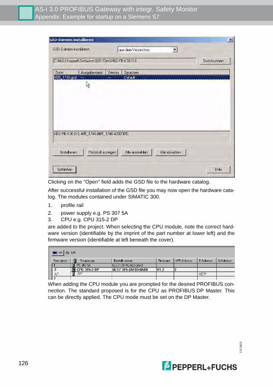
2.5
.201
3
AS-i 3.0 PROFIBUS Gateway with integr. Safety MonitorAppendix: Example for startup on a Siemens S7
Clicking on the "Open" field adds the GSD file to the hardware catalog.After successful installation of the GSD file you may now open the hardware cata-log. The modules contained under SIMATIC 300.1. profile rail2. power supply e.g. PS 307 5A3. CPU e.g. CPU 315-2 DPare added to the project. When selecting the CPU module, note the correct hard-ware version (identifiable by the imprint of the part number at lower left) and thefirmware version (identifiable at left beneath the cover).
When adding the CPU module you are prompted for the desired PROFIBUS con-nection. The standard proposed is for the CPU as PROFIBUS DP Master. Thiscan be directly applied. The CPU mode must be set on the DP Master.
126
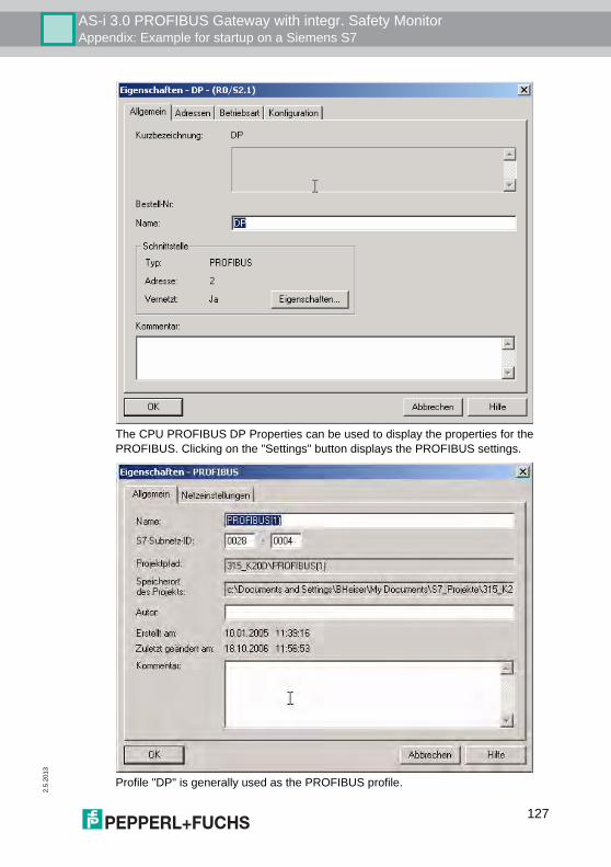
AS-i 3.0 PROFIBUS Gateway with integr. Safety MonitorAppendix: Example for startup on a Siemens S7
2.5.
2013
The CPU PROFIBUS DP Properties can be used to display the properties for thePROFIBUS. Clicking on the "Settings" button displays the PROFIBUS settings.
Profile "DP" is generally used as the PROFIBUS profile.
127
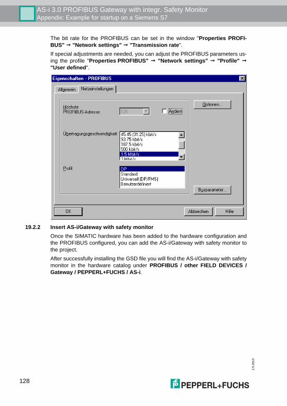
2.5
.201
3
AS-i 3.0 PROFIBUS Gateway with integr. Safety MonitorAppendix: Example for startup on a Siemens S7
The bit rate for the PROFIBUS can be set in the window "Properties PROFI-BUS" # "Network settings" # "Transmission rate".If special adjustments are needed, you can adjust the PROFIBUS parameters us-ing the profile "Properties PROFIBUS" # "Network settings" # "Profile" #"User defined".
19.2.2 Insert AS-i/Gateway with safety monitorOnce the SIMATIC hardware has been added to the hardware configuration andthe PROFIBUS configured, you can add the AS-i/Gateway with safety monitor tothe project.After successfully installing the GSD file you will find the AS-i/Gateway with safetymonitor in the hardware catalog under PROFIBUS / other FIELD DEVICES /Gateway / PEPPERL+FUCHS / AS-i.
128
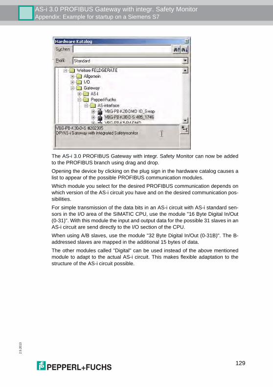
AS-i 3.0 PROFIBUS Gateway with integr. Safety MonitorAppendix: Example for startup on a Siemens S7
2.5.
2013
The AS-i 3.0 PROFIBUS Gateway with integr. Safety Monitor can now be addedto the PROFIBUS branch using drag and drop.Opening the device by clicking on the plug sign in the hardware catalog causes alist to appear of the possible PROFIBUS communication modules.Which module you select for the desired PROFIBUS communication depends onwhich version of the AS-i circuit you have and on the desired communication pos-sibilities.For simple transmission of the data bits in an AS-i circuit with AS-i standard sen-sors in the I/O area of the SIMATIC CPU, use the module "16 Byte Digital In/Out(0-31)". With this module the input and output data for the possible 31 slaves in anAS-i circuit are send directly to the I/O section of the CPU.When using A/B slaves, use the module "32 Byte Digital In/Out (0-31B)". The B-addressed slaves are mapped in the additional 15 bytes of data.The other modules called "Digital" can be used instead of the above mentionedmodule to adapt to the actual AS-i circuit. This makes flexible adaptation to thestructure of the AS-i circuit possible.
129
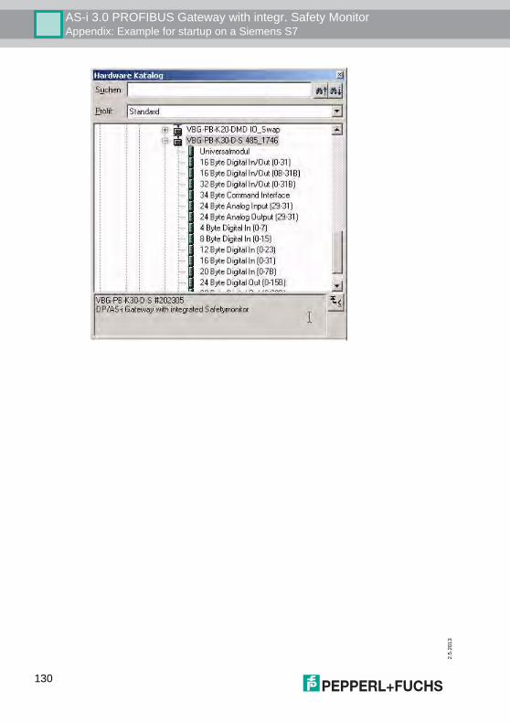
2.5
.201
3
AS-i 3.0 PROFIBUS Gateway with integr. Safety MonitorAppendix: Example for startup on a Siemens S7
130
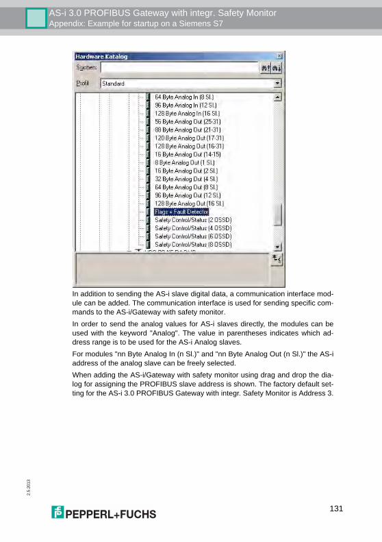
AS-i 3.0 PROFIBUS Gateway with integr. Safety MonitorAppendix: Example for startup on a Siemens S7
2.5.
2013
In addition to sending the AS-i slave digital data, a communication interface mod-ule can be added. The communication interface is used for sending specific com-mands to the AS-i/Gateway with safety monitor.In order to send the analog values for AS-i slaves directly, the modules can beused with the keyword "Analog". The value in parentheses indicates which ad-dress range is to be used for the AS-i Analog slaves.For modules "nn Byte Analog In (n Sl.)" and "nn Byte Analog Out (n Sl.)" the AS-iaddress of the analog slave can be freely selected.When adding the AS-i/Gateway with safety monitor using drag and drop the dia-log for assigning the PROFIBUS slave address is shown. The factory default set-ting for the AS-i 3.0 PROFIBUS Gateway with integr. Safety Monitor is Address 3.
131
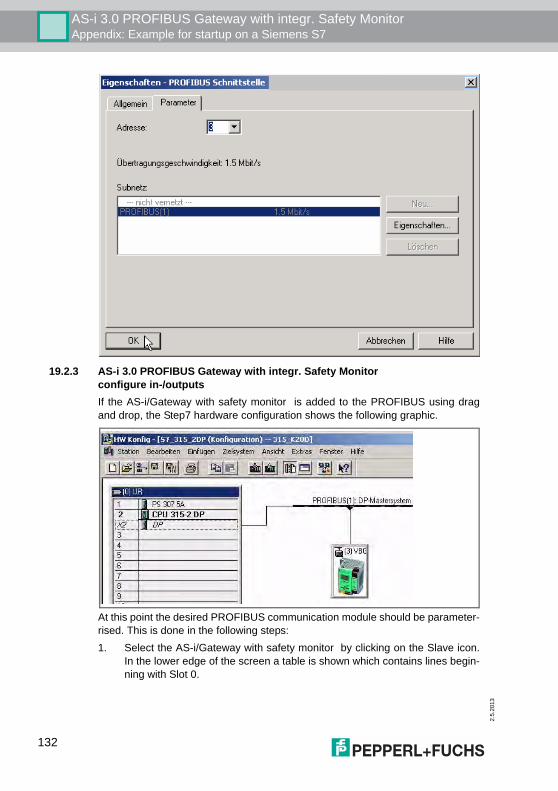
2.5
.201
3
AS-i 3.0 PROFIBUS Gateway with integr. Safety MonitorAppendix: Example for startup on a Siemens S7
19.2.3 AS-i 3.0 PROFIBUS Gateway with integr. Safety Monitorconfigure in-/outputsIf the AS-i/Gateway with safety monitor is added to the PROFIBUS using dragand drop, the Step7 hardware configuration shows the following graphic.
At this point the desired PROFIBUS communication module should be parameter-rised. This is done in the following steps:1. Select the AS-i/Gateway with safety monitor by clicking on the Slave icon.
In the lower edge of the screen a table is shown which contains lines begin-ning with Slot 0.
132
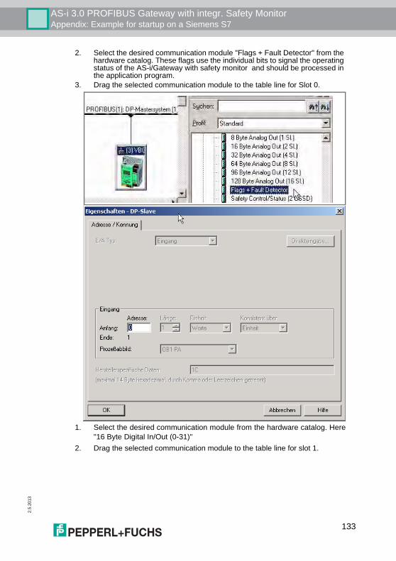
AS-i 3.0 PROFIBUS Gateway with integr. Safety MonitorAppendix: Example for startup on a Siemens S7
2.5.
2013
2. Select the desired communication module "Flags + Fault Detector" from the hardware catalog. These flags use the individual bits to signal the operating status of the AS-i/Gateway with safety monitor and should be processed in the application program.
3. Drag the selected communication module to the table line for Slot 0.
1. Select the desired communication module from the hardware catalog. Here"16 Byte Digital In/Out (0-31)"
2. Drag the selected communication module to the table line for slot 1.
133
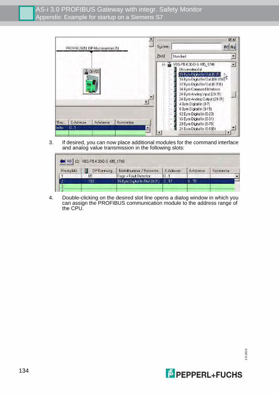
2.5
.201
3
AS-i 3.0 PROFIBUS Gateway with integr. Safety MonitorAppendix: Example for startup on a Siemens S7
3. If desired, you can now place additional modules for the command interface and analog value transmission in the following slots:
4. Double-clicking on the desired slot line opens a dialog window in which you can assign the PROFIBUS communication module to the address range of the CPU.
134
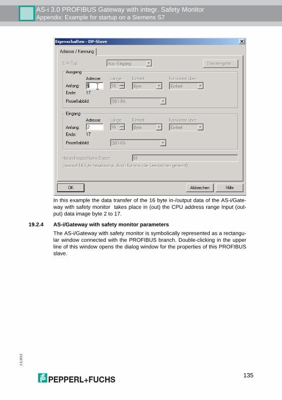
AS-i 3.0 PROFIBUS Gateway with integr. Safety MonitorAppendix: Example for startup on a Siemens S7
2.5.
2013
In this example the data transfer of the 16 byte in-/output data of the AS-i/Gate-way with safety monitor takes place in (out) the CPU address range Input (out-put) data image byte 2 to 17.
19.2.4 AS-i/Gateway with safety monitor parametersThe AS-i/Gateway with safety monitor is symbolically represented as a rectangu-lar window connected with the PROFIBUS branch. Double-clicking in the upperline of this window opens the dialog window for the properties of this PROFIBUSslave.
135
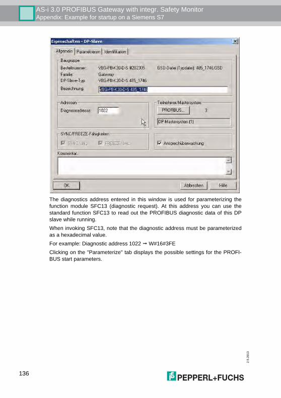
2.5
.201
3
AS-i 3.0 PROFIBUS Gateway with integr. Safety MonitorAppendix: Example for startup on a Siemens S7
The diagnostics address entered in this window is used for parameterizing thefunction module SFC13 (diagnostic request). At this address you can use thestandard function SFC13 to read out the PROFIBUS diagnostic data of this DPslave while running.When invoking SFC13, note that the diagnostic address must be parameterizedas a hexadecimal value.For example: Diagnostic address 1022 # W#16#3FEClicking on the "Parameterize" tab displays the possible settings for the PROFI-BUS start parameters.
136
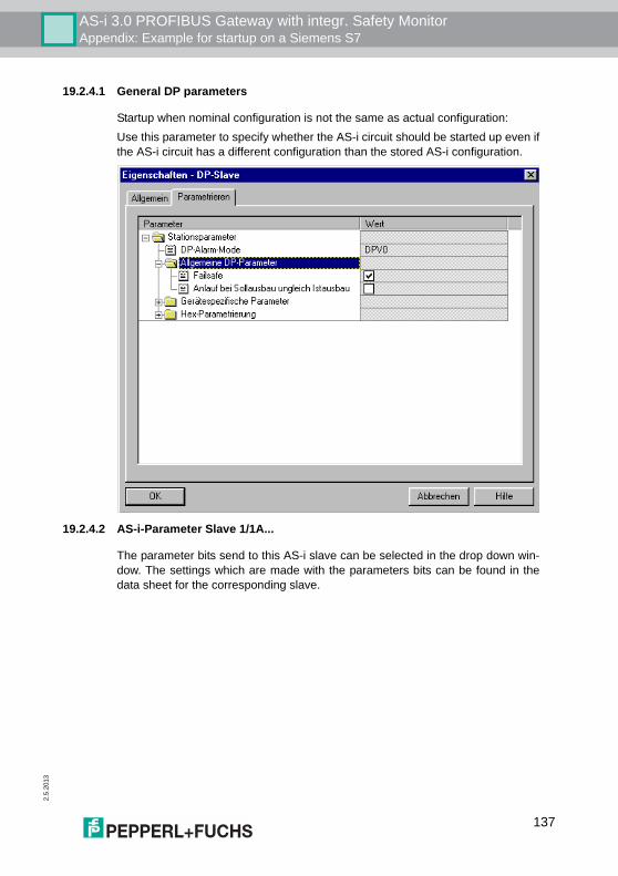
AS-i 3.0 PROFIBUS Gateway with integr. Safety MonitorAppendix: Example for startup on a Siemens S7
2.5.
2013
19.2.4.1 General DP parameters
Startup when nominal configuration is not the same as actual configuration:Use this parameter to specify whether the AS-i circuit should be started up even ifthe AS-i circuit has a different configuration than the stored AS-i configuration.
19.2.4.2 AS-i-Parameter Slave 1/1A...
The parameter bits send to this AS-i slave can be selected in the drop down win-dow. The settings which are made with the parameters bits can be found in thedata sheet for the corresponding slave.
137
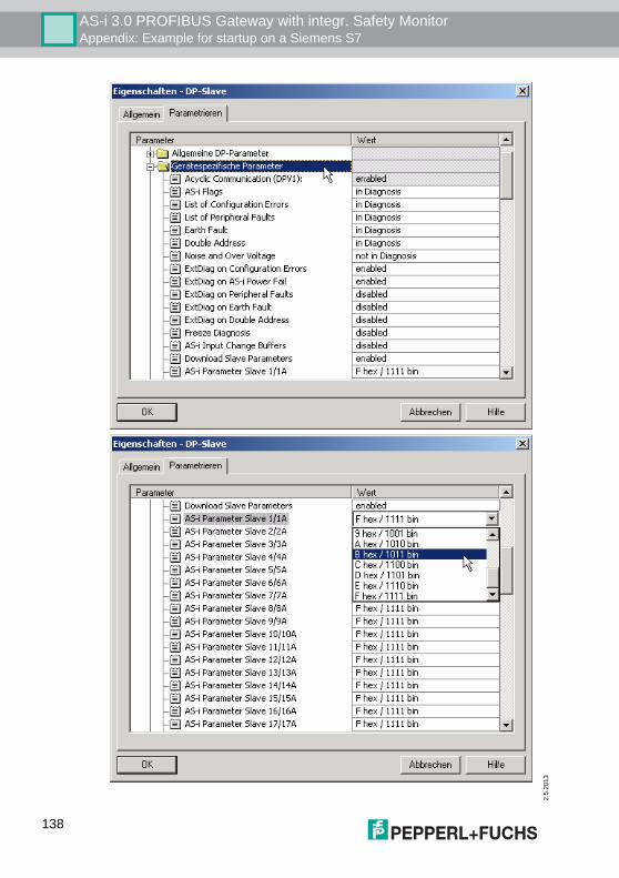
2.5
.201
3
AS-i 3.0 PROFIBUS Gateway with integr. Safety MonitorAppendix: Example for startup on a Siemens S7
138
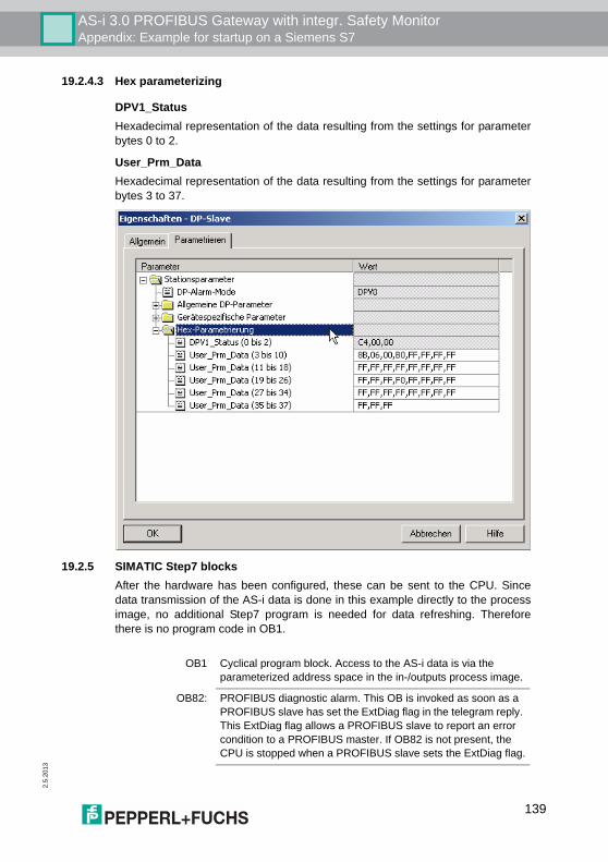
AS-i 3.0 PROFIBUS Gateway with integr. Safety MonitorAppendix: Example for startup on a Siemens S7
2.5.
2013
19.2.4.3 Hex parameterizing
DPV1_StatusHexadecimal representation of the data resulting from the settings for parameterbytes 0 to 2.
User_Prm_DataHexadecimal representation of the data resulting from the settings for parameterbytes 3 to 37.
19.2.5 SIMATIC Step7 blocksAfter the hardware has been configured, these can be sent to the CPU. Sincedata transmission of the AS-i data is done in this example directly to the processimage, no additional Step7 program is needed for data refreshing. Thereforethere is no program code in OB1.
OB1 Cyclical program block. Access to the AS-i data is via the parameterized address space in the in-/outputs process image.
OB82: PROFIBUS diagnostic alarm. This OB is invoked as soon as a PROFIBUS slave has set the ExtDiag flag in the telegram reply. This ExtDiag flag allows a PROFIBUS slave to report an error condition to a PROFIBUS master. If OB82 is not present, the CPU is stopped when a PROFIBUS slave sets the ExtDiag flag.
139
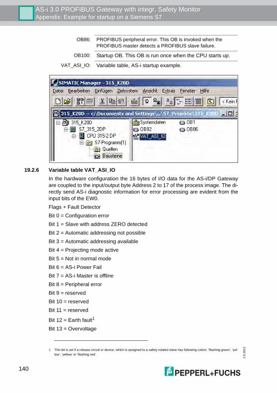
2.5
.201
3
AS-i 3.0 PROFIBUS Gateway with integr. Safety MonitorAppendix: Example for startup on a Siemens S7
19.2.6 Variable table VAT_ASI_IOIn the hardware configuration the 16 bytes of I/O data for the AS-i/DP Gatewayare coupled to the input/output byte Address 2 to 17 of the process image. The di-rectly send AS-i diagnostic information for error processing are evident from theinput bits of the EW0.Flags + Fault DetectorBit 0 = Configuration errorBit 1 = Slave with address ZERO detectedBit 2 = Automatic addressing not possibleBit 3 = Automatic addressing availableBit 4 = Projecting mode activeBit 5 = Not in normal modeBit 6 = AS-i Power FailBit 7 = AS-i Master is offlineBit 8 = Peripheral errorBit 9 = reservedBit 10 = reservedBit 11 = reserved
Bit 12 = Earth fault1
Bit 13 = Overvoltage
OB86: PROFIBUS peripheral error. This OB is invoked when the PROFIBUS master detects a PROFIBUS slave failure.
OB100: Startup OB. This OB is run once when the CPU starts up.
VAT_ASI_IO: Variable table, AS-i startup example.
1. This bit is set if a release circuit or device, which is assigned to a safety related slave has following colors: ’flashing green’, ’yel-low’, ’yellow’ or ’flashing red’.
140
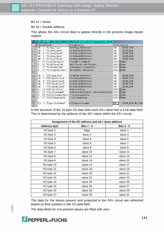
AS-i 3.0 PROFIBUS Gateway with integr. Safety MonitorAppendix: Example for startup on a Siemens S7
2.5.
2013
Bit 14 = NoiseBit 15 = Double addressThis allows the AS-i circuit data to appear directly in the process image inputs/outputs.
In the structure of the 16 byte I/O data field each AS-i slave has a 4-bit data field.This is determined by the address of the AS-i slave within the AS-i circuit.
The data for the slaves present and projected in the AS-i circuit are refreshedbased on their position in the I/O data field.The data fields for non-present slaves are filled with zero.
Assignment of the I/O address and AS-i slave addressAddress byte Bits 7 - 4 Bits 3 - 0
I/O byte 2 flags slave 1I/O byte 3 slave 2 slave 3I/O byte 4 slave 4 slave 5I/O byte 5 slave 6 slave 7I/O byte 6 slave 8 slave 9I/O byte 7 slave 10 slave 11I/O byte 8 slave 12 slave 13I/O byte 9 slave 14 slave 15I/O byte 10 slave 16 slave 17I/O byte 11 slave 18 slave 19I/O byte 12 slave 20 slave 21I/O byte 13 slave 22 slave 23I/O byte 14 slave 24 slave 25I/O byte 15 slave 26 slave 27I/O byte 16 slave 28 slave 29I/O byte 17 slave 30 slave 31
141
2.5
.201
3
AS-i 3.0 PROFIBUS Gateway with integr. Safety MonitorAppendix: Example for startup on a Siemens S7
This means for example the AS-i data for the AS-i slave having Address 12 occu-py bits 7 - 4 in I/O byte 8 of the controller.
19.2.6.1 AS-i flags byte 0, input bits 7 - 4
In order to check the current operating status of the AS-i circuit, the AS-i flags re-freshed with each PROFIBUS cycle can be used. These for flags occupy bits 7 - 4in input byte 0.
AS-i Config Error:Bit 4: 0 = AS-i configuration OK, 1 = AS-i configuration faultyIf during running the gateway AS-i master detects a discrepancy between thenominal configuration and the actual configuration, this bit is set. This allows thecontrol program to react to a faulty AS-i slave.
AS-i Power FailBit 5: 0 = AS-i power OK, 1 = AS-i power failWhen there is a failure of the AS-i supply voltage, this is indicated by the AS-ipower fail bit.
AS-i Peripheral ErrorBit 6: 0 = AS-i peripheral OK, 1 = AS-i peripheral errorThis bit indicates that there is a peripheral error on an AS-i slave. This may resultfor example from incorrect parameterizing of the AS-i slave.
AS-i Configuration ActiveBit 7: 0 = AS-i configuration is active, 1 = AS-i configuration is inactive.This bit indicates whether the AS-i gateway is in protected mode (Bit 7 = 0) or inprojecting mode.
19.2.6.2 AS-i flags byte 0, output bits 7 - 4
Output bits 7 - 4 in byte 0 can be used to affect the status of the AS-i circuit by thecontroller.
AS-i Off LineBit 4: 0 = Online, 1 = OfflineUse this bit to enable/disable the data cycle of the AS-i circuit. If the AS-i Master isin offline mode, no AS-i communication with the AS-i slaves will take place.
AS-i LOS Master BitBit 5: 0 = Offline when AS-i configuration error disabled, 1 = enabledIf this bit is set, the AS-i Master immediately switches to the offline phase andstops AS-i communication when an AS-i configuration error is detected. This re-sults in the connected AS-i output modules immediately switching to safe mode(outputs turned off).
Information!It is recommended that the AS-i flags be checked in the control program and torespond according to the reported states.
142
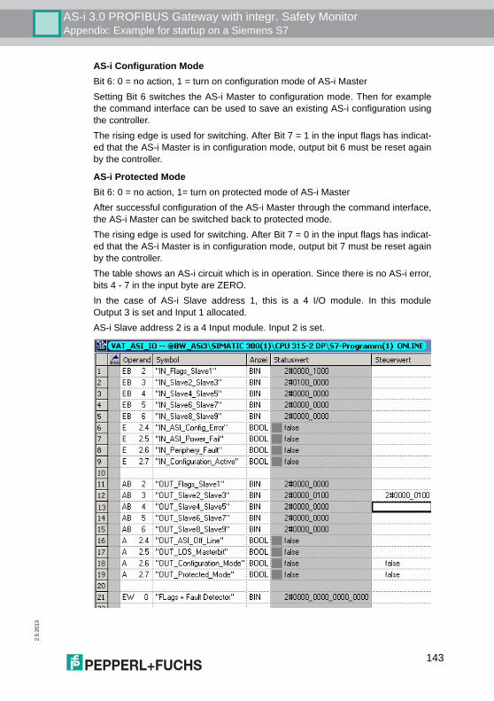
AS-i 3.0 PROFIBUS Gateway with integr. Safety MonitorAppendix: Example for startup on a Siemens S7
2.5.
2013
AS-i Configuration ModeBit 6: 0 = no action, 1 = turn on configuration mode of AS-i MasterSetting Bit 6 switches the AS-i Master to configuration mode. Then for examplethe command interface can be used to save an existing AS-i configuration usingthe controller.The rising edge is used for switching. After Bit 7 = 1 in the input flags has indicat-ed that the AS-i Master is in configuration mode, output bit 6 must be reset againby the controller.
AS-i Protected ModeBit 6: 0 = no action, 1= turn on protected mode of AS-i MasterAfter successful configuration of the AS-i Master through the command interface,the AS-i Master can be switched back to protected mode.The rising edge is used for switching. After Bit 7 = 0 in the input flags has indicat-ed that the AS-i Master is in configuration mode, output bit 7 must be reset againby the controller.The table shows an AS-i circuit which is in operation. Since there is no AS-i error,bits 4 - 7 in the input byte are ZERO.In the case of AS-i Slave address 1, this is a 4 I/O module. In this moduleOutput 3 is set and Input 1 allocated.AS-i Slave address 2 is a 4 Input module. Input 2 is set.
143
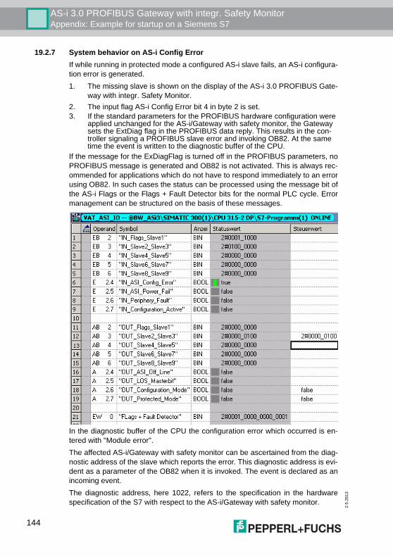
2.5
.201
3
AS-i 3.0 PROFIBUS Gateway with integr. Safety MonitorAppendix: Example for startup on a Siemens S7
19.2.7 System behavior on AS-i Config ErrorIf while running in protected mode a configured AS-i slave fails, an AS-i configura-tion error is generated.1. The missing slave is shown on the display of the AS-i 3.0 PROFIBUS Gate-
way with integr. Safety Monitor.2. The input flag AS-i Config Error bit 4 in byte 2 is set.3. If the standard parameters for the PROFIBUS hardware configuration were
applied unchanged for the AS-i/Gateway with safety monitor, the Gateway sets the ExtDiag flag in the PROFIBUS data reply. This results in the con-troller signaling a PROFIBUS slave error and invoking OB82. At the same time the event is written to the diagnostic buffer of the CPU.
If the message for the ExDiagFlag is turned off in the PROFIBUS parameters, noPROFIBUS message is generated and OB82 is not activated. This is always rec-ommended for applications which do not have to respond immediately to an errorusing OB82. In such cases the status can be processed using the message bit ofthe AS-i Flags or the Flags + Fault Detector bits for the normal PLC cycle. Errormanagement can be structured on the basis of these messages.
In the diagnostic buffer of the CPU the configuration error which occurred is en-tered with "Module error".The affected AS-i/Gateway with safety monitor can be ascertained from the diag-nostic address of the slave which reports the error. This diagnostic address is evi-dent as a parameter of the OB82 when it is invoked. The event is declared as anincoming event.The diagnostic address, here 1022, refers to the specification in the hardwarespecification of the S7 with respect to the AS-i/Gateway with safety monitor.
144
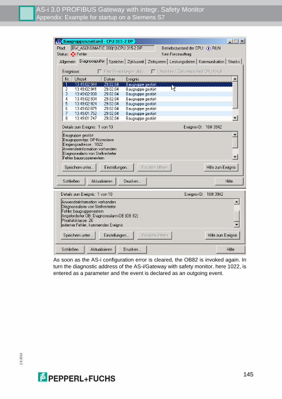
AS-i 3.0 PROFIBUS Gateway with integr. Safety MonitorAppendix: Example for startup on a Siemens S7
2.5.
2013
As soon as the AS-i configuration error is cleared, the OB82 is invoked again. Inturn the diagnostic address of the AS-i/Gateway with safety monitor, here 1022, isentered as a parameter and the event is declared as an outgoing event.
145
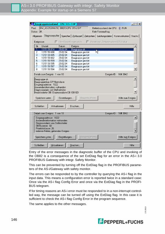
2.5
.201
3
AS-i 3.0 PROFIBUS Gateway with integr. Safety MonitorAppendix: Example for startup on a Siemens S7
Entry of the error messages in the diagnostic buffer of the CPU and invoking ofthe OB82 is a consequence of the set ExtDiag flag for an error in the AS-i 3.0PROFIBUS Gateway with integr. Safety Monitor.This can be prevented by turning off the ExtDiag flag in the PROFIBUS parame-ters of the AS-i/Gateway with safety monitor.The errors can be responded to by the controller by querying the AS-i flag in theinput data. This means a configuration error is reported twice in a standard case:Once via the AS-i flag Config Error and once via the ExtDiag flag in the PROFI-BUS telegram.If for timing reasons an AS-i error must be responded to in a non-interrupt control-led way, the message can be turned off using the ExtDiag flag. In this case it issufficient to check the AS-i flag Config Error in the program sequence.The same applies to the other messages.
146
AS-i 3.0 PROFIBUS Gateway with integr. Safety MonitorAppendix: Example for startup on a Siemens S7
2.5.
2013
If the message for various error states of the AS-i/Gateway with safety monitor isactivated via the PROFIBUS and if the data for the PROFIBUS diagnostic dataare enabled, the SIEMENS function module SFC13 can be used to retrieve thePROFIBUS diagnostic data of the AS-i Gateway and save them to a data module.Use of SFC13 is described in detail in the SIEMENS documentation for PROFI-BUS.
19.3 Device-specific parameters
Acyclic CommunicationEin-/Ausschalten der azyklischen #variable<Feldbus>#-Kommunikation nachdem DPV1-Standard (nicht änderbar).Default: Kommunikation nach DPV1 eingeschaltet.
AS-i FlagsSpecifies whether the AS-i flags are sent in the #variable<Feldbus># diagnostic.Default: Transmission in the #variable<Feldbus># diagnostic data.
Download Slave ParametersBased on this entry the parameter bits can be downloaded for each AS-i slave.These are then sent to the connected AS-i slave when the AS-i cycle is started.Sending of the set parameters bits can be disabled with this value.Default: Sending of the AS-i parameter bits enabled.
Double AddressThe AS-i/Gateway with safety monitor detects when there is double addressing.This list can be sent with the diagnostic data.Default: Transmission in the #variable<Feldbus># diagnostic data.
Earth FaultThe AS-i/Gateway with safety monitor can detect an earth (ground) fault. The in-formation as to whether there is or is not an earth fault is sent in the diagnostic da-ta.Default: Transmission in the #variable<Feldbus># diagnostic data.
ExtDiag on Configuration ErrorsWhen an AS-i configuration error occurs, the AS-i/Gateway with safety monitorsets the ExtDiag flag in its #variable<Feldbus># data reply. By setting this flag theProfibus DP slave tells the #variable<Feldbus># master that there is an error con-dition and that the diagnostic data are being updated.In the case of the S7 controller invoking of the OB82 is triggered when an ExtDiagflag is set. If the latter is not present, the controller is stopped.
147

2.5
.201
3
AS-i 3.0 PROFIBUS Gateway with integr. Safety MonitorAppendix: Example for startup on a Siemens S7
Setting this ExtDiag flag can be suppressed using this parameter. Consequentlyno interrupt controlled OB82 invoking is triggered in the controller, and the con-troller must then respond to a possible AS-i configuration error by checking theAS-i flag in the input data.Default: Setting of the ExtDiag flag for AS-i configuration error is enabled.
ExtDiag on AS-i Power FailActivates and deactivates setting of the ExtDiag flag on AS-i power fail.Default: Setting of the ExtDiag flag on AS-i power fail is enabled.
ExtDiag on Peripheral FaultsActivates and deactivates setting of the ExtDiag flag on peripheral faults.Default: Setting of the ExtDiag flag on peripheral faults disabled.
ExtDiag on Earth FaultActivates and deactivates setting of the ExtDiag flag on earth (ground) fault.Default: Setting of the ExtDiag flag on earth fault is disabled.
ExtDiag on Double AddressActivates and deactivates setting of the ExtDiag flag on double address.Default: Setting of the ExtDiag flag on double address is disabled.
ExtDiag on Safety StatusSet the ExtDiagFlag when there is a safety slave with red or yellow flashing de-vice.Default: Set ExtDiagFlag for safety slaves with red or yellow flashing device.
Failsafe BehaviourSetting the master response when an AS-i slave fails.Clear all bits: Input data are set to 0hex (standard)
Set all bits: Input data are set to Fhex.
Retain old value: Input data are left at the last valid value.Default: Input data are set to 0hex
Freeze DiagnosisThe diagnostic data are continuously updated during runtime. If this is not de-sired, this parameter can be used to disable continuous updating. Updating thentakes place only when this is required by the #variable<Feldbus># standard.
Input Data FilterFiltering of the input data by the specified number of AS-i cycles.Default: No filtering of the input data.
Language
148
AS-i 3.0 PROFIBUS Gateway with integr. Safety MonitorAppendix: Example for startup on a Siemens S7
2.5.
2013
Selection of the displayed language.Default: no change of the displayed language.
List of Configuration ErrorsThe AS-i/Gateway with safety monitor saves a list of all AS-i slaves which havetriggered a present configuration error. This list can be sent with the #varia-ble<Feldbus># diagnostic data.Default: Transmission in the #variable<Feldbus># diagnostic data.
List of Peripheral FaultsThe AS-i/Gateway with safety monitor saves a list of all AS-i slaves which havetriggered a peripheral errors. This list can be sent with the PROFIBUS diagnosticdata.Default: Transmission in the #variable<Feldbus># diagnostic data.
Noise and Over voltageThe AS-i/Gateway with safety monitor analyzes the quality of the AS-i voltageduring running. This assessment can be sent with the diagnostic data.Default: Not transmitted in the #variable<Feldbus># diagnostic data.
Safety StatusSafety slaves whose device is in the red or yellow flashing state can be shown inthe diagnostics.Default: Display of device status enabled in diagnostics.
149

2.5
.201
3
AS-i 3.0 PROFIBUS Gateway with integr. Safety MonitorCodes indicated by the display
20. Codes indicated by the display
In the basic state of the configuration mode, the addresses of all detected slavesare displayed in two-second intervals. A blank display indicates that the LDS (Listof Detected Slaves) is empty, no slaves were detected. In the basic state of the protected operating mode, the display is either blank ordisplays the address of a faulty assignment.During manual address programming, the slave address display has a differentmeaning (see also chapter "Operating in advanced display mode").All displayed numbers bigger than 31 which can not be interpreted as a slave ad-dress are status or error messages of the master. They have the following mean-ings:
39 Advanced AS-i diagnostics: After pressing the ’set’-button a short-time AS-i power failure occurred.
40 The AS-i master is in offline phase.
41 The AS-i master is in detection phase.
42 The AS-i master is in activation phase.
43 The AS-i master starts the normal operating mode.
68 Hardware error: disturbed internal communication.
69 Hardware error: disturbed internal communication.
70 Hardware error: The AS-i master’s EEPROM cannot be written.
71 Wrong PIC-type.
72 Hardware error: wrong PIC-processor.
73 Hardware error: wrong PIC-processor.
74 Checksum error in the EEPROM.
75 Error in the internal RAM.
76 Error in the external RAM.
77 AS-i control software error: Stack overflow (AS-i control II)
78 AS-i control software error: checksum error in the control program."control checksum":checksumm in Control III C program (bin.file) not correct. The file is possibly damaged."control exec err":error in Control III C program."control watchdog":watchdog predetermined in Control III C program has expired ."control incomp":Control III C program from another gateway type loaded (e.g. Ethernet IP in Profibus gateway).
150
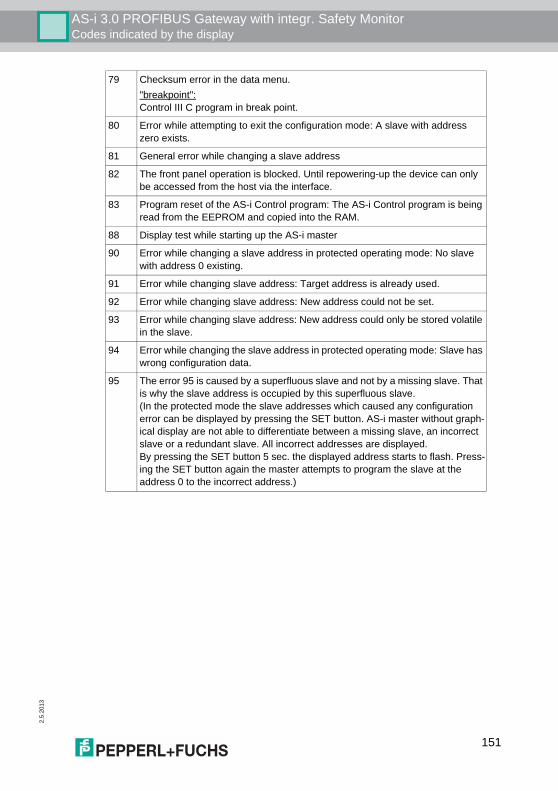
AS-i 3.0 PROFIBUS Gateway with integr. Safety MonitorCodes indicated by the display
2.5.
2013
79 Checksum error in the data menu."breakpoint":Control III C program in break point.
80 Error while attempting to exit the configuration mode: A slave with address zero exists.
81 General error while changing a slave address
82 The front panel operation is blocked. Until repowering-up the device can only be accessed from the host via the interface.
83 Program reset of the AS-i Control program: The AS-i Control program is being read from the EEPROM and copied into the RAM.
88 Display test while starting up the AS-i master
90 Error while changing a slave address in protected operating mode: No slave with address 0 existing.
91 Error while changing slave address: Target address is already used.
92 Error while changing slave address: New address could not be set.
93 Error while changing slave address: New address could only be stored volatile in the slave.
94 Error while changing the slave address in protected operating mode: Slave has wrong configuration data.
95 The error 95 is caused by a superfluous slave and not by a missing slave. That is why the slave address is occupied by this superfluous slave.(In the protected mode the slave addresses which caused any configuration error can be displayed by pressing the SET button. AS-i master without graph-ical display are not able to differentiate between a missing slave, an incorrect slave or a redundant slave. All incorrect addresses are displayed.By pressing the SET button 5 sec. the displayed address starts to flash. Press-ing the SET button again the master attempts to program the slave at the address 0 to the incorrect address.)
151
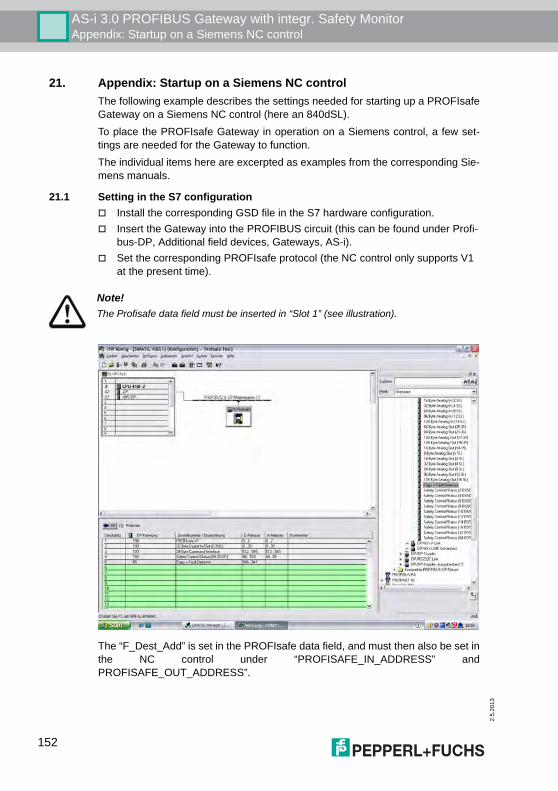
2.5
.201
3
AS-i 3.0 PROFIBUS Gateway with integr. Safety MonitorAppendix: Startup on a Siemens NC control
21. Appendix: Startup on a Siemens NC controlThe following example describes the settings needed for starting up a PROFIsafeGateway on a Siemens NC control (here an 840dSL).To place the PROFIsafe Gateway in operation on a Siemens control, a few set-tings are needed for the Gateway to function.The individual items here are excerpted as examples from the corresponding Sie-mens manuals.
21.1 Setting in the S7 configuration" Install the corresponding GSD file in the S7 hardware configuration." Insert the Gateway into the PROFIBUS circuit (this can be found under Profi-
bus-DP, Additional field devices, Gateways, AS-i)." Set the corresponding PROFIsafe protocol (the NC control only supports V1
at the present time).
The “F_Dest_Add” is set in the PROFIsafe data field, and must then also be set inthe NC control under “PROFISAFE_IN_ADDRESS” andPROFISAFE_OUT_ADDRESS”.
Note!The Profisafe data field must be inserted in “Slot 1” (see illustration).
152
AS-i 3.0 PROFIBUS Gateway with integr. Safety MonitorAppendix: Startup on a Siemens NC control
2.5.
2013
21.2 Setting in the NC controlThe “PROFISAFE_MASTER_ADDRESS“ is taken from the hardware configura-tion (F_Source_Address) and entered in number 10385.
Example:
21.3 Setting “PROFISAFE_IN_ADDRESS“The “PROFISAFE_IN_ADDRESS“ must be set in two 32-bit fields so that the 64-bit Gateway input data can be addressed.
Example:
21.4 Setting “PROFISAFE_OUT_ADDRESS“The “PROFISAFE_OUT_ADDRESS“ must be set analogous to the“PROFISAFE_IN_ADDRESS“ so that all 64 bits can also be addressed here.
Example:
21.5 Setting “PROFISAFE_IN_ASSIGN“Here you enter in which data range the safe input bits are entered in the INSE.
Example:
10385 7D2 (corresponds to 2002 decimal)
10386[0] 050000CA (corresponds to 202 decimal, from the hardware configuration, F-destination address, the 5 at the beginning stands for Profi-bus, addresses the first 32 bits of the input data).
10386[1] 050100CA (corresponds to 202 decimal, from the hardware configuration, F-destination address, the 5 at the beginning stands for Profi-bus, addresses bits 33-64 of the input data).
10387[0] 050000CA (corresponds to 202 decimal, from the hardware configuration, F-destination address, the 5 at the beginning stands for Profi-bus, addresses the first 32 bits of the output data)
10387[1] 050100CA (corresponds to 202 decimal, from the hardware configuration, F-destination address, the 5 at the beginning stands for Profi-bus, addresses bits 33-64 of the output data).
10388[0] 001032 (The first 32 bits are mapped from 1 to 32).10388[1] 033064 (The next 32 bits are mapped from 33 to 64).
153
2.5
.201
3
AS-i 3.0 PROFIBUS Gateway with integr. Safety MonitorAppendix: Startup on a Siemens NC control
21.6 Setting “PROFISAFE_OUT_ASSIGN"Here you enter from which data range the safe output bits are taken from theOUTSE.
Example:
21.7 Setting “PROFISAFE_IN_FILTER"Here the filter is defined which is used to write the data from the“PROFISAFE_IN_ADDRESS“ to the “PROFISAFE_IN_ASSIGN“. In this examplethere is no filter, rather all data are passed directly.
Example:
21.8 Setting “PROFISAFE_OUT_FILTER"Here the filter is defined for writing the data from the“PROFISAFE_OUT_ASSIGN“ to the “PROFISAFE_OUT_ADDRESS". In this ex-ample there is no filter, rather all data are passed directly.
Example:
10389[0] 001032 (The first 32 bits are mapped from 1 to 32).
10389[1] 033064 (The next 32 bits are mapped from 33 to 64).
13300[0] FFFFFFFF13300[1] FFFFFFFF
Information!The first byte INSE 1 is reserved in the upper example! Slave 1 is mapped to the INSE 2. If it is not intended, we recommend you the following setting:13300[0] FFFFFFFE13300[1] FFFFFFFFSlave 1 is mapped to the INSE 1 in this example.
13300[0] FFFFFFFF13300[1] FFFFFFFF
154
AS-i 3.0 PROFIBUS Gateway with integr. Safety MonitorReference List
2.5.
2013
155
22. Reference List
22.1 Manual: “ASIMON 3 G2 Configuration Software“This Manual contains a detailed description of the configuration software for theAS-i Safety Monitor. The manual is an important component of the documentationfor the AS-i Safety Monitor. It is not possible to configure and start up the AS-iSafety Monitor without the ASIMON 3 G2 software.
22.2 Sources1. Kriesel, Werner R.; Madelung, Otto W. (editors): AS-interface. Das Aktua-
tor-Sensor-Interface für die Automation. Auflage, Carl Hanser Verlag;München, Wien, 1999, ISBN 3-446-21064-4
2. Spezifikation des AS-interface, ComSpec V3.0 AS-international Association (available from AS-international Association, http://www.as-interface.net).
3. Vorschlag eines Grundsatzes für die Prüfung und Zertifizierung von „Bussystemen für die Übertragung sicherheitsrelevanter Nachrichten“, Stand 29.2.2000.
4. AS-interface - Die Lösung in der Automation, Ein Kompendium über Tech-nik, Funktion, Applikation (erhältlich, auch in englischer Sprache, bei AS-international Association, http://www.as-interface.net).