Manual Aqua TROLL 100 & 200 Manual
94
May 2012 Aqua TROLL 100 Aqua TROLL 200 Innovations in Water Monitoring Operator’s Manual
Transcript of Manual Aqua TROLL 100 & 200 Manual

May 2012
Aqua TROLL 100Aqua TROLL 200
Innovations inWater Monitoring
Operator’s Manual

Copyright © 2008-2012 by In-Situ Inc. All rights reserved. Revision history released January 2007 rev. 001 March 2007 rev. 002 September 2007 rev. 003 September 2008 rev. 004 March 2010 rev. 005 March 2011 rev. 006 May 2012
This document contains proprietary information which is protected by copyright. No part of this document may be photocopied, reproduced, or translated to another language without the prior written consent of In-Situ Inc.
Mailing & Shipping Address: Phone: 970-498-500 In-Situ Inc. Fax: 970-498-1598 221 East Lincoln Avenue Internet: www.in-situ.com Fort Collins, CO 80524 Support Line: 800-446-7488 U.S.A. (U.S.A. & Canada)
The information in this document is subject to change without notice. In-Situ Inc. has made a reasonable effort to be sure that the information contained herein is current and accurate as of the date of publication.
In-Situ Inc. makes no warranty of any kind with regard to this material, including, but not limited to, its fitness for a particular application. In-Situ will not be liable for errors contained herein or for incidental or consequential damages in connection with the furnishing, performance, or use of this material.
In no event shall In-Situ Inc. be liable for any claim for direct, incidental, or consequential damages arising out of, or in connection with, the sale, manufacture, delivery, or use of any product.
Images in this manual have been selected for illustration; actual images may vary from those shown.
In-Situ and the In-Situ logo, Baro Merge, BaroTROLL, Hermit, Pocket-Situ, RDO, RuggedCable, RuggedReader, TROLL and Win-Situ are trademarks or registered trademarks of In-Situ Inc. Microsoft, Windows, Excel, Internet Explorer, Windows Mobile, Windows Vista, ActiveSync, and Windows Mobile Device Center are trademarks or registered trademarks of Microsoft Corporation. Pentium is a registered trademark of Intel. Tefzel and Delrin are registered trademarks of E. I. DuPont de Nemours and Company. Viton is a registered trademark of DuPont Dow Elastomers. Kellems is a registered trademark of Hubbell Inc. Alconox is a registered trademark of Alconox Company. Lime-A-Way is a registered trademark of Reckitt Benckiser. Other brand names and trademarks are property of their respective owners.

Page 3 Aqua TROLL Operator’s Manual
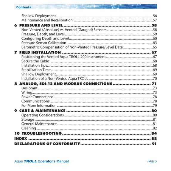
Contents1 INTRODUCTION ......................................................................... 6
System Description ..........................................................................................................................6How to Use This Manual ..................................................................................................................6
Conventions ................................................................................................................................8Certification .........................................................................................................................................8Unpacking and Inspection .............................................................................................................8
Serial Number ............................................................................................................................8To Our Customers . . . ........................................................................................................................9
Warranty Provisions ...............................................................................................................10How to Contact Us ..........................................................................................................................10
To Obtain Repair Service (U.S.A.) .......................................................................................10Guidelines for Cleaning Returned Equipment .............................................................12
2 SYSTEM COMPONENTS ............................................................ 14Instrument..........................................................................................................................................14Cable ...................................................................................................................................................14Small Desiccant ...............................................................................................................................17
Communication Cables ........................................................................................................18Power Components ........................................................................................................................19Installation Accessories .................................................................................................................20Control Software ..............................................................................................................................21Product Specifications–General .................................................................................................22
Product Specifications–Conductivity Sensor ...............................................................23Product Specifications–Pressure (Aqua TROLL 200 Instrument) ...........................24

Page 4Aqua TROLL Operator’s Manual
Contents
Product Specifications–Temperature ..............................................................................24Product Specifications–Footnotes ....................................................................................25
3 GETTING STARTED ................................................................... 26Select a TROLL Com for Communication ................................................................................27Install the Software .........................................................................................................................28
USB TROLL Com Drivers ........................................................................................................28Win-Situ Mobile .......................................................................................................................28Win-Situ Sync ............................................................................................................................28
Connect the Hardware...................................................................................................................29USB TROLL Com .......................................................................................................................29Twist-Lock Cable Connections ...........................................................................................30
4 USING WIN-SITU® 5 SOFTWARE ................................................ 33Launch the Software and Connect Instrument ....................................................................33The Home Screen ............................................................................................................................35
Customizing the Home Screen Display ..........................................................................36Set the Clock ......................................................................................................................................37Add a Site ............................................................................................................................................38Check the Conductivity Calibration .........................................................................................42Prepare to Log Data ........................................................................................................................43
Tips for Aqua TROLL Data Logs ..........................................................................................44Disconnect .........................................................................................................................................46
5 CONDUCTIVITY ........................................................................ 47About Conductivity ........................................................................................................................47
How is Conductivity Measured? ........................................................................................47Calibration ..........................................................................................................................................48
Preparing to Calibrate ...........................................................................................................49Calibration Procedure............................................................................................................51
Available Parameters ......................................................................................................................55
Page 5Aqua TROLL Operator’s Manual
Contents
Shallow Deployment ......................................................................................................................56Maintenance and Recalibration ................................................................................................57
6 PRESSURE AND LEVEL .............................................................. 58Non-Vented (Absolute) vs. Vented (Gauged) Sensors ........................................................58Pressure, Depth, and Level ...........................................................................................................59Configuring Depth and Level ......................................................................................................60Pressure Sensor Calibration ........................................................................................................63Barometric Compensation of Non-Vented Pressure/Level Data ....................................65
7 FIELD INSTALLATION ............................................................... 67Positioning the Vented Aqua TROLL 200 Instrument .........................................................67Secure the Cable ..............................................................................................................................68Installation Tips.................................................................................................................................68Stabilization Time ............................................................................................................................69Shallow Deployment ......................................................................................................................69Installation of a Non-Vented Aqua TROLL ..............................................................................70
8 ANALOG, SDI-12 AND MODBUS CONNECTIONS ........................... 71Desiccant ............................................................................................................................................73Wiring ...................................................................................................................................................73Power Connections .........................................................................................................................78Communications .............................................................................................................................78For More Information .....................................................................................................................79
9 CARE & MAINTENANCE ............................................................ 80Operating Considerations ............................................................................................................80Storage ................................................................................................................................................81General Maintenance .....................................................................................................................81Cleaning ..............................................................................................................................................82
10 TROUBLESHOOTING ............................................................... 84INDEX ....................................................................................... 88DECLARATIONS OF CONFORMITY .................................................. 91
Page 6 Aqua TROLL Operator’s Manual
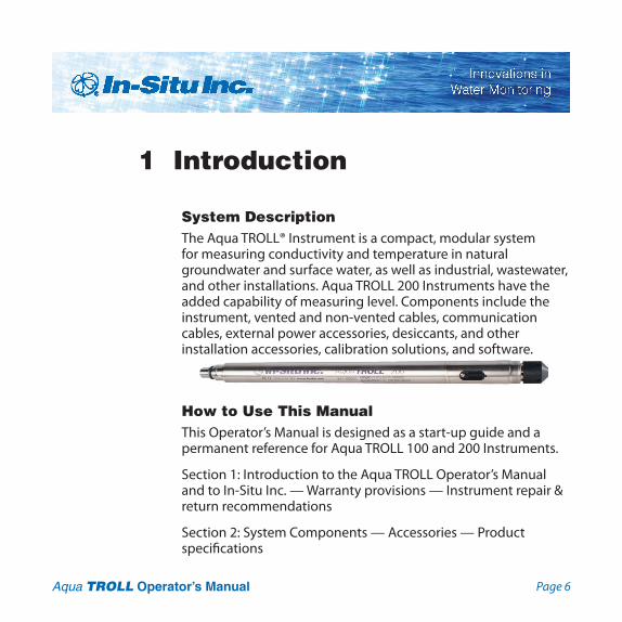
1 Introduction
System Description The Aqua TROLL® Instrument is a compact, modular system for measuring conductivity and temperature in natural groundwater and surface water, as well as industrial, wastewater, and other installations. Aqua TROLL 200 Instruments have the added capability of measuring level. Components include the instrument, vented and non-vented cables, communication cables, external power accessories, desiccants, and other installation accessories, calibration solutions, and software.
How to Use This ManualThis Operator’s Manual is designed as a start-up guide and a permanent reference for Aqua TROLL 100 and 200 Instruments.
Section 1: Introduction to the Aqua TROLL Operator’s Manual and to In-Situ Inc. — Warranty provisions — Instrument repair & return recommendations
Section 2: System Components — Accessories — Product specifications

Page 7Aqua TROLL Operator’s Manual
Section 1: Introduction
Section 3: Getting Started — Attaching cable — Installing and opening the software
Section 4: Using Win-Situ — Connecting for the first time — Customizing the Home screen — Setting the clock — Setting a device site — Calibrating conductivity — Preparing to log data — Disconnecting
Section 5: The Conductivity Sensor: Description — Calibration — Available parameters
Section 6: The Pressure (Level) Sensor: The two basic types of pressure sensors — Factory and field calibration
Section 7: Field Installation — Guidelines and precautions for long-term deployment of the Aqua TROLL Instrument
Section 8: Connecting for Use with SDI-12, Analog (4-20 mA), and Modbus Loggers and Controllers
Section 9: Care and Maintenance
Section 10: Troubleshooting
The check mark highlights a tip about a convenient feature of the Aqua TROLL Instrument.
The exclamation point calls your attention to a requirement or important action that should not be overlooked.
Page 8Aqua TROLL Operator’s Manual
Section 1: Introduction
TIP: Please save packing materials for future storage
and shipping of your Aqua TROLL Instrument. The shipping boxes have been performance-tested and provide protection for the instrument and its accessories.
Conventions
Throughout this operator’s manual you will see the following symbols.
CertificationThe Aqua TROLL Instrument complies with all applicable directives required by CE and the FCC and found to comply with EN 61326, ICES-003, and FCC Part 15 specifications. Declarations of conformity may be found at end of this manual.
Unpacking and InspectionYour Aqua TROLL Instrument was carefully inspected before shipping. Check for any physical damage sustained during shipment. Notify In-Situ and file a claim with the carriers involved if there is any such damage; do not attempt to operate the instrument. Accessories may be shipped separately and should also be inspected for physical damage and the fulfillment of your order.
Serial Number
The serial number is engraved on the body of the instrument. It is also programmed into the instrument and displayed when the instrument is connected to a computer running Win-Situ® 5 or Win-Situ® Mobile Software. We recommend that owners keep a separate record of this number.
Page 9Aqua TROLL Operator’s Manual
Section 1: Introduction
Bob Blythe, President and CEO In-Situ Inc. [email protected]
To Our Customers . . .
Thank you for your purchase of an In-Situ product. We are glad you chose us and our products to help you with your environmental monitoring needs. In-Situ Inc. has been designing and manufacturing world-class environmental monitoring instrumentation for over 25 years in the Rocky Mountains of the United States. As it was in the beginning, our expectation is that this product will provide you with many trouble-free years of use. To that end, we pride ourselves on delivering the best customer service and support possible—24 hours a day, 7 days a week. We believe that this level of commitment to you, our customer, is imperative in helping you ensure clean, safe groundwater and surface water resources around the globe. We also understand the need for accurate, reliable assessments and we continue to make significant investments in Research and Development to ensure that we deliver the latest product and technological innovations to support your needs.
Whether you are gathering information about a body of water for a few moments, or over a period of years, you can rely upon us to provide you with a quality product and outstanding customer support at a fair price and have that product delivered to you when and where you need it.
We want your experience with In-Situ Inc. to be pleasant and professional, whether you are renting or purchasing from us. We would be pleased to hear from you and to learn more about your needs and your experiences with our products. Again, we thank you for choosing In-Situ Inc. and we look forward to serving your needs now, and in the future.

Page 10Aqua TROLL Operator’s Manual
Section 1: Introduction
Warranty Provisions
In-Situ® Inc., (In-Situ) warrants that all new Aqua TROLL® 100 and 200 Instruments shall be free from defects in materials and workmanship for a period of two years when properly installed and operated in accordance with the instruction manuals provided by, or available through, In-Situ Inc., and when used within the design specifications for the product. Products and accessory products including batteries, which are manufactured by others, carry the warranty of that manufacturer, or 30 days, whichever is greater. The warranty period for all products begins on the day the product is shipped to the customer or distributor.The complete Warranty Policy is available on the In-Situ website.
How to Contact UsTechnical Support: 800-446-7488, option 3Toll-free 24 hours a day in the U.S.A. and Canada
Address: In-Situ Inc. 221 East Lincoln Ave. Fort Collins, CO 80524 U.S.A.Phone: 970-498-1500Fax: 970-498-1598Internet: www.in-situ.come-mail: [email protected]
To Obtain Repair Service (U.S.A.)
If you suspect that your instrument is malfunctioning and repair is re quired, you can help ensure efficient servicing by following these guidelines:
1. Call or e-mail In-Situ Technical Support ([email protected]). Have the equipment with you when you call.

Page 11Aqua TROLL Operator’s Manual
Section 1: Introduction
2. Be prepared to describe the problem, including how the instrument was used and the conditions noted at the time of the malfunction.
3. If Tech Support determines that service is needed, they will ask that you download and complete a Return Materials Authorization Form available on the In-Situ website under Contact/Returns for Service.
4. Clean the instrument and cable. Decontaminate thoroughly if it has been used in a toxic or hazardous environment. See the Cleaning Guidelines and form on page 13.
5. Remove all sensors and accessories that are not required for the repair prior to returning unit.
6. Mark the RMA number clearly on the side of the box with a marker or label.
Please keep your RMA number for future reference. Return unit for repair to the following address:
In-Situ Inc. Attn: RMA #XXXXX 221 E. Lincoln Ave. Fort Collins, CO 80524 U.S.A.
To reduce waste, please use your original shipping container, if it is in good condition.
The warranty does not cover damage during transit. We recom-mend the customer insure all shipments. Warranty repairs will be shipped back prepaid.
TIP: Please keep your RMA number for future reference.

Page 12Aqua TROLL Operator’s Manual
Section 1: Introduction
Outside the U.S.A.Contact your international In-Situ distributor for repair and service information.
Guidelines for Cleaning Returned Equipment
Please help us protect the health and safety of our employees by cleaning and decontaminating equipment that has been subjected to any potential biological or health hazards, and labeling such equipment. Unfortunately, we cannot service your equipment without such notification. Please complete and sign the form on page 13 (or a similar statement certifying that the equipment has been cleaned and decontaminated) and send it along to us with each downhole instrument.
• Werecommendacleaningsolution,suchasAlconox®,aglassware cleaning product available from In-Situ (Catalog No. 0029810) and laboratory supply houses.
• DO NOT remove the nose cone. DO NOT use any object to clean the sensor face.
• Cleanthepressuresensorbysoakingonlyincleaningsolutionor clean water.
• Clean all cabling. Remove all foreign matter.
• Cleancableconnector(s)withaclean,drycloth.Donotsubmerge.
• Cleantheprobebody—includingthenosecone,cablehead,and protective caps. Remove all foreign matter.
If an instrument returned for servicing shows
evidence of having been deployed in a toxic or hazardous environment, Customer Service personnel will require written proof of decontamination before they can service the unit.
Page 13Aqua TROLL Operator’s Manual
Section 1: Introduction
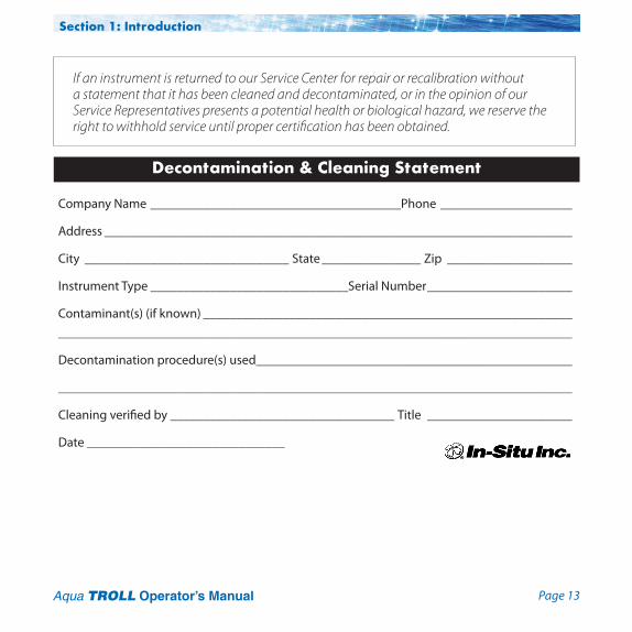
Company Name ______________________________________Phone ____________________
Address _______________________________________________________________________
City _______________________________ State _______________ Zip ___________________
Instrument Type ______________________________Serial Number ______________________
Contaminant(s) (if known) ________________________________________________________ ______________________________________________________________________________
Decontamination procedure(s) used________________________________________________
______________________________________________________________________________
Cleaning verified by __________________________________ Title ______________________
Date ______________________________
Decontamination & Cleaning Statement
If an instrument is returned to our Service Center for repair or recalibration without a statement that it has been cleaned and decontaminated, or in the opinion of our Service Representatives presents a potential health or biological hazard, we reserve the right to withhold service until proper certification has been obtained.

Page 14 Aqua TROLL Operator’s Manual
There are no user-serviceable parts in the Aqua TROLL Instrument.
TIP: Cable marking VF = vent-free
InstrumentThe completely sealed Aqua TROLL Instrument contains conductivity and temperature sensors, real-time clock, microprocessor, sealed lithium battery, data logger, and memory. Aqua TROLL 200 Instruments include a vented or non-vented pressure sensor in a variety of ranges.
Cable Several basic cable types are used in the Aqua TROLL system.
• RuggedCable®System,TPU-jacketed(ThermoplasticPolyurethane), vented or non-vented
• VentedTefzel®-jacketedcable(ETFEfluoropolymer)• Poly-coated stainless steel suspension wire for deployment of
a non-vented instrument• Communicationcablesforprogrammingthedevice/
downloading the logged data
2 System Components

Page 15Aqua TROLL Operator’s Manual
Section 2: System Components
RuggedCable® SystemCable includes conductors for power and communication signals, a weight-bearing structure, and a Kellems® grip to anchor the Aqua TROLL Instrument securely. Cable is available in standard and custom lengths.
Uphole and downhole ends are identical female twist-lock connectors that connect to the Aqua TROLL Instrument, cable connect TROLL® Com devices, desiccants, and other accessories.
Vented cable must be used with vented pressure/level sensors on the Aqua TROLL 200 to achieve gauged measuresments. The cable vent tube ensures that atmospheric pressure is the reference pressure applied to the sensor diaphragm.
Vented cable ships with a small desiccant cap that should be replaced with a larger volume desiccant before you deploy the instrument in a humid environment.
Non-vented cable may be used with non-vented pressure/level sensors on the Aqua TROLL 100 or 200 Instruments to achieve absolute measurements. Vented cable can also be used.

Page 16Aqua TROLL Operator’s Manual
to Aqua TROLL
Section 2: System Components
RuggedCable Stripped-And-Tinned In place of the uphole twist-lock connector, this cable ends in bare conductors for wiring to a logger or controller using SDI-12, analog (4-20 mA), or Modbus communication protocols. Vented cable includes an outboard desiccant to protect against condensation.
Also available in a shorter length ending in a male twist-lock connector to mate with RuggedCable.
For connections, refer to wiring diagrams in Section 8.
to RuggedCable
to PLC or logger
to Aqua TROLL
to PLC or logger
Suspension WirePoly-coated stainless steel suspension cable is ideal for deployment of instruments with non-vented pressure sensors.
Page 17Aqua TROLL Operator’s Manual
Section 2: System Components
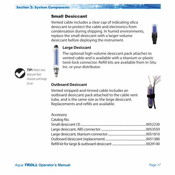
Small Desiccant Vented cable includes a clear cap of indicating silica desiccant to protect the cable and electronics from condensation during shipping. In humid environments, replace the small desiccant with a larger-volume desiccant before deploying the instrument.
Large DesiccantThe optional high-volume desiccant pack attaches to vented cable and is available with a titanium or plastic twist-lock connector. Refill kits are available from In-Situ Inc. or your distributor.
Outboard DesiccantVented stripped-and-tinned cable includes an outboard desiccant pack attached to the cable vent tube, and is the same size as the large desiccant. Replacements and refills are available.
Accessory Catalog No.Small desiccant (3) ...........................................................................................0052230Large desiccant, ABS connector ...............................................................0053550Large desiccant, titanium connector .....................................................0051810Outboard desiccant (replacement) ........................................................0051380Refill kit for large & outboard desiccant ...............................................0029140
TIP: Protect new desiccant from moisture until ready to use.

Page 18Aqua TROLL Operator’s Manual
Communication Cables
TROLL Com devices enable an instrument to communicate with a desktop/laptop PC or handheld PDA for profiling, calibrating, programming, and downloading. TROLL Com devices include 0.9 m (3 ft) vented polyurethane cable, external power input jack, and a vent with replaceable membrane.
TROLL Com (Cable Connect)Connects a RuggedCable to a serial or USB port. It is weatherproof and withstands a temporary immersion (IP67).
TROLL Com (Direct Connect)Connects an Aqua TROLL Instrument directly to a serial or USB port. It is a good choice for permanent connection to a PC, or for programming a non-vented Aqua TROLL Instrument that will be deployed without RuggedCable. It is not submersible or designed for harsh field conditions.
Accessory Catalog No.RS232 TROLL Com, Cable Connect .........................................................0056140USB TROLL Com, Cable Connect ..............................................................0052500RS232 TROLL Com, Direct Connect ........................................................0056150USB TROLL Com, Direct Connect .............................................................0052510
Section 2: System Components
The computer connectors are not submersible.
External power input
Vent
RS232 or USB connector
Twist-lock connector

Page 19Aqua TROLL Operator’s Manual
Section 2: System Components
Power ComponentsInternal PowerThe Aqua TROLL Instrument operates on 3.6 VDC, supplied by a sealed, non-replaceable AA lithium battery. Battery life depends on sampling speed. The battery typically lasts for 5 years or 200,000 readings, whichever occurs first. One reading is defined as date, time, and all available parameters polled or logged from the device.
External PowerExternal Battery Pack The sealed, submersible TROLL Battery Pack (lithium) supplies 14.4 V. When this power source is connected, the Aqua TROLL Instrument will use the external battery source first and switch to the internal batteries when external battery power is depleted. Typical external battery life when logging all available parameters at 2-minute intervals is approximately 2 years.
AC AdapterIn-Situ’s AC adapter provides 24 VDC, 0.75 A, AC input 100-250 V, includes North American power cord. The Programming Cable includes an external power input for connection to this adapter.
Accessory Catalog No.External Battery Pack ......................................................................................0051450AC Adapter 24V .................................................................................................0052440
TIP: Win-Situ 5 can display the approximate
percentage of internal battery life remaining when the Aqua TROLL Instrument is connected to a computer.
TIP: When an Aqua TROLL Instrument is used as an Analog
(4-20 mA), SDI-12, or Modbus device, power is supplied by the data logger or controller to which the Aqua TROLL Instrument is wired.
Use only In-Situ’s AC adapter. Damage to the Aqua TROLL
Instrument caused by the use of third-party converters is not covered by the warranty.

Page 20Aqua TROLL Operator’s Manual
Section 2: System Components
Installation Accessories• Twist-LockHanger:titaniumhangertosealandsuspenda
non-vented Aqua TROLL Instrument while taking data; no venting, no communication capabilities
• CableExtender:connectstwolengthsofRuggedCable• Wellcaps,lockingandvented• WellDocks:top-of-wellsupportfor2”,4”,or6”well• Panel-mountedbulkheadforconnectiontoRuggedCable
Accessory Catalog No.Twist-lock Hanger, titanium ..........................................................0051480Cable Extender ..................................................................................0051490LockingWellcap,2” .........................................................................0020360LockingWellcap,2”vented ..........................................................0020370LockingWellcap,4” .........................................................................0020380LockingWellcap,4”vented ..........................................................0020390Top-of-well installation ring ......................................WELLDOCK2”,4”,6”Bulkhead connector ........................................................................0053240
Twist-lock Hanger
Cable Extender
Locking Wellcap
Well Dock
Bulkhead Connector

Page 21Aqua TROLL Operator’s Manual
Section 2: System Components
Control SoftwareWin-Situ® 5 Software is easy-to-use software for programming Aqua TROLL Instruments.
Win-Situ provides instrument control for direct reads and profiling, calibration, long-term data logging, data downloads, data viewing, data export to popular spreadsheet programs, choice of units and other display options, and battery/memory usage tracking. Win-Situ® Plus enables configuration of networks and telemetry.
Minimum system requirements: 400 MHz Pentium® II processor; 128 MB RAM, 100 MB free disk space; Internet Explorer® 6.01 or higher; Windows® 2000 Professional SP4 or higher, Windows XP Professional SP2 or higher, or Windows Vista SP1 or higher; Windows 7 or higher, CD-ROM drive; serial or USB port.
Win-Situ® Mobile Software provides the features and functions of Win-Situ 5 on a field-portable platform. Requirements: In-Situ RuggedReader® Handheld PC with Microsoft Windows Mobile® operating system (RuggedReader, Windows Mobile 5 or later), serial communications port, and at least 16 MB for data storage (SD card, CF card, or the device’s built-in non-volatile memory). For installation and file exchange, Windows® 7 requires Windows® Mobile Device Center to be installed on the computer. Earlier versions of Windows require Microsoft® ActiveSync®.
Accessory Catalog No.Win-Situ 5 (no license required) ................................................................0051980Win-Situ 5 Plus license ...................................................................................0053560Win-Situ Mobile license for RuggedReader ............................0047520Win-Situ Mobile license (upgrade from Pocket-Situ 4) .......0047550

Page 22Aqua TROLL Operator’s Manual
Section 2: System Components
Product Specifications–General

Page 23Aqua TROLL Operator’s Manual
Section 2: System Components
Product Specifications–Conductivity Sensor

Page 24Aqua TROLL Operator’s Manual
Section 2: System Components
Product Specifications–Pressure (Aqua TROLL 200 Instrument)
Product Specifications–Temperature

Page 25Aqua TROLL Operator’s Manual
Section 2: System Components
Product Specifications–Footnotes

Page 26 Aqua TROLL Operator’s Manual
This section provides a quick overview of the initial steps necessary to get the instrument ready to communicate:
4 Select the appropriate TROLL Com for communication. This determinesthehardwareconnections,andmayinfluencethe software installation. The drawing on the following page shows the function of the different TROLL Com models.
4 Install the software.
4 Connect the hardware, based on the selected TROLL Com.
4 Open the software and establish communication with the Aqua TROLL Insturment. See Section 4 of this manual for an overview of Win-Situ operations.
3 Getting Started

Page 27Aqua TROLL Operator’s Manual
Select a TROLL Com for CommunicationThe figure below shows the function and connectability of the different models of TROLL Com.
Section 3: Getting Started
TIPS: A Direct Connect TROLL Com may be preferred for
programming an Aqua TROLL Instrument that will be deployed on wire.
RuggedCable and a Cable Connect TROLL Com are required for communication with the device while deployed, but programming can be done with any TROLL Com connection.
An RS232 (serial) TROLL Com is needed for use with a RuggedReader.
Serial port
RS232 connections
USB port
USB connections
Direct Connect TROLL Coms: Not designed for submersion
Cable Connect TROLL Coms: Designed for field use

Page 28Aqua TROLL Operator’s Manual
Section 3: Getting Started
Install the SoftwareInstall Win-Situ 5 Software from the In-Situ software/resource CD or from the In-Situ website:
• ClickonWin-Situ5,andfollowtheinstructionstoinstallWin-Situ 5 to your local hard drive.
USB TROLL Com Drivers
• IfusingaUSBTROLLCom,besuretoselecttheoption"InstallUSBTROLLComDrivers."Twodriverswillbeloadedtoyourhard drive, one for the USB TROLL Com, one for the USB TROLL Com serial port.
Win-Situ Mobile
For communication using a RuggedReader Handheld PC in the field, install the desktop component of Win-Situ Mobile on a desktop/laptop PC from the CD or website: The desktop component is called the Win-Situ Software Manager, and is needed to install Win-Situ Mobile on the RuggedReader.
1. Click on Win-Situ Mobile and follow the instructions to install the Win-Situ Software Manager to your local hard drive.
2. Connect the RuggedReader to the desktop computer, establish a connection in Microsoft ActiveSync®, launch the Win-Situ Software Manager, and follow the instructions to install Win-Situ Mobile on the RuggedReader.
Win-Situ Sync
If you plan to synchronize log files from the RuggedReader to a PC after collecting data in the field, install Win-Situ Sync from the CD or website.
TIP: If using Windows 7, ensure that Windows
Mobile Device Center is installed. If using an operating system prior to Windows 7, ensure that Microsoft ActiveSync is installed on the desktop or laptop PC and a Guest connection or partnership has been established between the computers.
TIP: If using a USB TROLL Com, be sure to select the option
“Install USB TROLL Com Drivers” when installing Win-Situ 5.

Page 29Aqua TROLL Operator’s Manual
Connect the Hardware1. Connect the Aqua TROLL Instrument to the selected TROLL
Com as illustrated earlier in this section.• Direct Connect: Attach via push-on connection to the
Aqua TROLL back end.• Cable Connect: Connect the twist-lock connectors on the
Aqua TROLL Instrument and the RuggedCable.2. Insert the TROLL Com into the computer port.
USB TROLL Com
When you plug in a USB TROLL Com, the USB drivers that were downloaded when you installed Win-Situ 5 will be installed.• Afterinstallation,checkasfollowstofindwhichCOMportthe
connected USB TROLL Com is using:• Windows 2000, Windows XP: Control Panel > System >
Hardware tab > Device Manager > Ports. Click the plus sign to display the ports.
• Windows Vista and 7: Control Panel > System > Device Manager (Administrator permission required) > Ports. Click the plus sign to display the ports.
After connections are made, you are ready to launch the software and program the Aqua TROLL Instrument. Section 4 of this manual is an overview of Win-Situ. For more detailed information, see the Win-Situ Help menu.
Section 3: Getting Started

Page 30Aqua TROLL Operator’s Manual
Section 3: Getting Started
Twist-Lock Cable Connections
1. Remove the protective caps from the Aqua TROLL connector end and cable connector end.
2. Lookattheconnectors.Eachhasaflatside.
Note the pins on the instrument connector (one on each side) and the slots on the cable connector (one on each side).
Aqua TROLL(or Cable Connect TROLL Com) Cable
TIP: Retain the dust caps to protect the pins and O-ring from damage when cable is not attached.
Pin Slot
Cable
Flat Flat
Aqua TROLL(or Cable Connect TROLL Com)
Page 31Aqua TROLL Operator’s Manual
Section 3: Getting Started
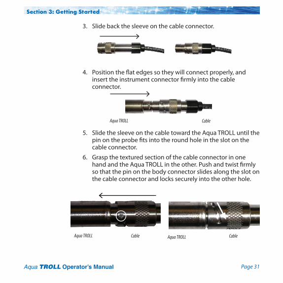
3. Slide back the sleeve on the cable connector.
4. Positiontheflatedgessotheywillconnectproperly,andinsert the instrument connector firmly into the cable connector.
5. Slide the sleeve on the cable toward the Aqua TROLL until the pin on the probe fits into the round hole in the slot on the cable connector.
6. Grasp the textured section of the cable connector in one hand and the Aqua TROLL in the other. Push and twist firmly so that the pin on the body connector slides along the slot on the cable connector and locks securely into the other hole.
Aqua TROLL Cable
Aqua TROLL Cable Aqua TROLL Cable
Page 32Aqua TROLL Operator’s Manual
Section 3: Getting Started
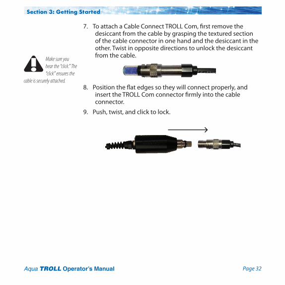
7. To attach a Cable Connect TROLL Com, first remove the desiccant from the cable by grasping the textured section of the cable connector in one hand and the desiccant in the other. Twist in opposite directions to unlock the desiccant from the cable.
8. Positiontheflatedgessotheywillconnectproperly,andinsert the TROLL Com connector firmly into the cable connector.
9. Push, twist, and click to lock.
Make sure you hear the “click.” The “click” ensures the
cable is securely attached.

Page 33 Aqua TROLL Operator’s Manual
4 Using Win-Situ® 5 Software
Win-Situ 5 Software is the In-Situ instrument control software for Aqua TROLL Instruments. Use Win-Situ to:
• Displayreal-timereadingsfromtheconnectedAquaTROLL, in meter, tabular, or graphic format
• Programthedevicetologdata;downloadtheloggeddata
• Calibratetheconductivitysensor,selectoutputparametersand units
• Customizetheoutputofapressure/levelsensortorecorddrawdown, surface water elevation, gauge height, stage height, etc.
• Setcommunicationoptionsinthedevice—Modbus,SDI-12, analog, IP, telemetry, etc.
Launch the Software and Connect Instrument1. Start Win-Situ by double-clicking the shortcut created
on the desktop during installation.
TIP: Win-Situ Mobile provides Win-Situ 5 features
and functionality in a convenient field-worthy platform.

Page 34Aqua TROLL Operator’s Manual
Section 4: Using Win-Situ
Win-SituopensanddisplaystheDataarea(“Datatab”),shown below.
2. Check the COM port. The software may ask if you want to select a COM port. Do one of the following:4 Answer Yes to the prompt, then check or change the port
in the Comm Settings dialog, and click OK to close it, or
4 Answer No to bypass this step.
3. Win-Situ asks if you want to connect to the device. If the Aqua TROLL instrument is connected to your computer as described in the previous section, answer Yes.
Connect button
C:\Documents and Settings\ [Login] \My Documents\WinSitu Data
2
3
Data tab
TIP: For direct serial connection the port is usually COM 1. This
is the Win-Situ default.
For USB communication, be sure to select the correct COM port.
TIP: You can turn off the “Connect now?” prompt:
Select Prefrences menu > General Settings, deselect “Prompt for connect at startup,” click OK. In this case, connect to the device by clicking the Connect button
.

Page 35Aqua TROLL Operator’s Manual
Section 4: Using Win-Situ
4. Software connects and displays a reading of all supported parameters.
The Home Screen4 Note the Tabs at the top of the screen—this is the Home tab,
which displays current readings from the connected device.
4 The Dashboard (status area) shows the device model & serial number, battery and memory usage, clock, alarms, and logging status.
4 The Control Panel contains action buttons. To update the readings in real time, press .
Note:Whenthisbuttonlooks“pressedin” , polling is active. Before you can perform certain software tasks, you will need to stop polling by pressing the button again.
Control Panel
Home tab
Tabs
Dashboard
Click here to update readings in real time Device is connected

Page 36Aqua TROLL Operator’s Manual
Section 4: Using Win-Situ
Customizing the Home Screen Display
Changing Units1. Click the Sensors tab , select the sensor for which you intend
to change units.2. Clickthe“Configure”button
in the control panel.3. In the Sensor Setup screen, select a
parameter, then select a unit. Repeat for each parameter as necessary.
4. Click OK to return to the Sensors tab.
Changing the Rate at Which the Readings UpdateAlso called the “pollrate,”thiscanrangefrom1to30seconds.1. Select Preferences > Home View Settings.2. Adjust the Poll Rate. Default: 5 seconds.
Changing the Decimal Places Displayed To change the number of decimal places displayed for each reading:1. Select Preferences > General Settings.2. Under Parameter Defaults, select a parameter, then the
“significantdecimaldigits”foreachparameter.
Real-Time GraphingToviewareal-timetrendgraph:clickthe“Graph”buttonTo view a graph with a data table below it, select Preferences > Graph Settings. Check the Data Panel option. Click OK.
TIP: Unit selection is not available if the device is polling or has an active log.
TIP: All parameters supported by the device are shown in
the Home screen by default. To change this, select Preferences > Home View Settings. Clear the check boxes for parameters you do not want to view.

Page 37Aqua TROLL Operator’s Manual
Section 4: Using Win-Situ
Set specific information in the software. Win-Situ provides many options. At a minimum: • SettheAquaTROLLclock.• Enteranameforthesitewheretheinstrumentwillcollect
data.• Calibratetheconductivitysensor.• Enterdatalogginginstructions.A brief overview is provided here. For more detailed information, see the Win-Situ Help menu.
Set the ClockData collection schedules depend on the device’s real-time clock. Both the device clock and the system (PC) clock are shown on the dashboard. The clocks update every 2 seconds. If the device clock differs by more than 2 seconds from the system clock, the device clock is displayed in red. To synchronize the clocks, click the“Sync”button.
TIP: The Preferences option on the Menu
bar allows users to configure instrument software, including: • General settings• Comm settings• Working directory• Graph settings• Home view settings• Data view settings
Clock Sync button
Device clock
PC clock

Page 38Aqua TROLL Operator’s Manual
Section 4: Using Win-Situ
Add a SiteLogged data are organized and filed by the site where the data were logged. This feature can help you manage data from multiple sites. You can create as many sites as you like, with or without an Aqua TROLL connected. Sites are stored in the site database in your Win-Situ working directory and are available to select for any Aqua TROLL, any log.
You will need a site when setting up a data log. Here are the steps to set up a new site:
1. On the Data tab, click the Site Data folder.
2. Select File menu > New > Site.
TIP: A default site is supplied and may be used, but it does
not contain any specific information on the location data collection site. For more information on sites, see Win-Situ Help menu.
Data tabSite Data folder
C:\Documents and Settings\ [Login] \My Documents\WinSitu Data\Site Data
TIP: You can also create a Site Group to organize multiple sites
within a Site Group folder.
Page 39Aqua TROLL Operator’s Manual
Section 4: Using Win-Situ
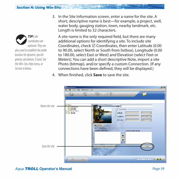
3. In the Site Information screen, enter a name for the site. A short, descriptive name is best—for example, a project, well, water body, gauging station, town, nearby landmark, etc. Length is limited to 32 characters.
A site name is the only required field, but there are many additional options for identifying a site. To include site Coordinates, check Coordinates, then enter Latitude (0.00 to 90.00, select North or South from listbox), Longitude (0.00 to 180.00, select East or West) and Elevation (select Feet or Meters). You can add a short descriptive Note, import a site Photo (bitmap), and/or specify a custom Connection. (If any connections have been defined, they will be displayed.)
4. When finished, click Save to save the site.
Name the site
Save the site
TIP: Site coordinates are optional. They are
also used to establish the probe location for dynamic specific gravity calculation, if used. See the Win-Situ Help menu, or Section 6 below.
Page 40Aqua TROLL Operator’s Manual
Section 4: Using Win-Situ
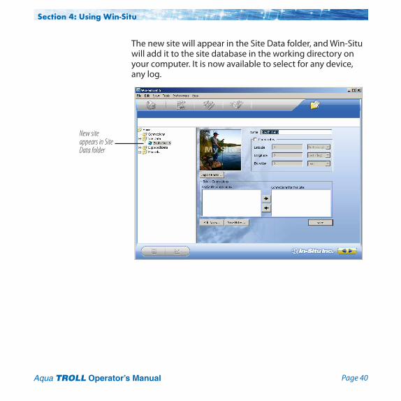
The new site will appear in the Site Data folder, and Win-Situ will add it to the site database in the working directory on your computer. It is now available to select for any device, any log.
New site appears in Site Data folder

Page 41Aqua TROLL Operator’s Manual
Section 4: Using Win-Situ
5. To set this new site in the connected Aqua TROLL Instrument: Return to the Home tab, click the down arrow beside the site box, and select your new site.
Thissitenowbecomesthe“current”sitefortheconnectedAqua TROLL Instrument, and is available to use in data logs.
Select the site

Page 42Aqua TROLL Operator’s Manual
Section 4: Using Win-Situ
Check the Conductivity Calibration The conductivity sensor in the Aqua TROLL has been calibrated during manufacturing to produce a linear response across the operating range.
We recommend you check the specific conductivity reading in the solution shipped with your instrument. If the device is reading accurately, there is no need to field-calibrate the instrument unless SOPs require it.
To perform a field calibration you will need:
4 The In-Situ Cal Cup, or other suitable container that allows for complete immersion of the conductivity sensor,includingthetemperature“button,”whichcan be seen on one side of the probe. The Cal Cup is recommended for the first calibration.
4 The calibration standard solution supplied, or other solution of known specific conductivity in the range 100 to 60,000 µS/cm.
The complete calibration procedure takes only a few minutes and may be done in a field or office/lab setting with a software connection in Win-Situ 5 or Win-Situ Mobile Software. A detailed description of the conductivity calibration procedure, including:
• PreparationoftheAquaTROLL• Softwareinput• Calculatedoutput• Hintsforsuccessfulcalibration
is in Section 5 of this manual.
For best results we recommend you read and follow
the conductivity calibration procedure in Section 5 of this Operator’s Manual.
Temperature
Conductivity
Pressure

Page 43Aqua TROLL Operator’s Manual
Section 4: Using Win-Situ
Prepare to Log Data1. To program the device to log data, go to the Logging tab.
2. Clickthe“New”button.
The Logging Setup Wizard will guide you through the configuration of a data log—including the site, log name, parameters to measure, sample schedule, start time, stop time, level output, and other options.
TIP: Stop “polling” in the Home screen before setting up a data log.
TIP: For more complete information on setting up data logs, see the Win-Situ Help menu.
Logging tab
“New” button

Page 44Aqua TROLL Operator’s Manual
Section 4: Using Win-Situ
Tips for Aqua TROLL Data Logs
• NineparametersareavailablefortheAquaTROLL200Instrument. Seven parameters are available for the Aqua TROLL 100 Instrument. All selected parameters are logged, with implications for battery and memory usage.
• Only one active log can reside in the device at a time. An active log is a log that is Ready, Pending, Running, or Suspended as shown in the Status column of the Logging Tab.
• ToavoiddrainingtheAquaTROLLbatteryprematurely,external power is required for Event logging, and recommended for Linear Average logging.
• ForinformationonselectingaLeveloutput,refertotheWin-Situ Help menu, or Section 6 in this manual.
• Foranon-vented Aqua TROLL that will be deployed on wire, be sure to select a Scheduled Start so the log will start by itself, without a communication connection.
• Formorecompleteinformationonsettingupdatalogs,seethe Win-Situ Help menu .

Page 45Aqua TROLL Operator’s Manual
Section 4: Using Win-Situ
To Start logging: • A“Pending”(scheduled)logwillstartatitsprogrammedtime.• Youcanstarta“Ready”(manual)logatanytime
whileconnectedbyselectingthelogandpressing“Start” .To Stop logging:
• Selectthelogandpressthe“Stop”button .• Orsuspend(temporarilystop)itwiththe“Pause”button .
To Download the log to the connected PC: • Selectthelogandpressthe“Download”button .
To View the log after downloading:• GototheDatatabandselectthelog;foragraphpress .
TIP: As an alternative to the log control buttons, right-click a log to display a short context menu of available actions.
TIP: The available log control buttons will vary depending on the status of the selected log.
Logging tab
“Start” button
“Ready” log
Log control buttons

Page 46Aqua TROLL Operator’s Manual
Section 4: Using Win-Situ
DisconnectAfter the Aqua TROLL is programmed to log data, you are ready to:
• Exitthesoftware(Filemenu>Exit).
• Disconnect the TROLL Com from the cable connector, by grasping the textured section of the cable connector in one hand and the TROLL Com in the other. Twist in opposite directions to unlock the TROLL Com from the cable.
• Ventedcable:Attach desiccant to the cable connector—line uptheflatsidesoftheconnectors,push,twist,andclicktolock the desiccant to the cable. Remove red dust cap from the desiccant’s vent.
• Non-ventedAquaTROLL(orinstallationswhereventedpressure or communication are not required): Attach a non-vented cable or twist-lock hanger and suspension wire.
• Installtheinstrumentinitsfieldlocation.SeeSection 7 for guidelines.
Remove the dust cap from the desiccant before
deployment to allow air to reach the cable vent tube.
Page 47 Aqua TROLL Operator’s Manual
5 ConductivityAbout ConductivityConductivity measures the ability of a material to carry an electric current. Generally, the higher the concentration of dissolved salts and minerals in water, the better the water is as a conductor, therefore the electrical conductivity is higher. Deionized/distilled water is a poor conductor because almost all anions and cations are removed during the deionization/distillation process.
If conductivity changes in a body of water, it often indicates an environmental event. For example, a dramatic increase in the electrical conductivity of an underground fresh water aquifer located near the ocean could indicate the beginning of saltwater intrusion. On the other hand, an increase in the electrical conductivity of a small lake that is completely surrounded by farmland may simply be the result of runoff from recent precipitation.
How is Conductivity Measured?
Conductance is the reciprocal of the resistance, in ohms, measured between two opposing electrodes of a 1 cm cube at a specific temperature. The unit 1/ohm or mho was given the name of Siemens (S) for conductance. It is not practical to require all conductance cells to have the dimensions of an exact cube. To

Page 48Aqua TROLL Operator’s Manual
Section 5: Conductivity
enable the comparison of data from experiments with different conductance cells, the conductance is multiplied by the cell constant to show conductivity in Siemens per centimeter (S/cm). Cell constants are determined for each sensor using a standard solution of known conductivity. The cell constant depends on the electrode area and the amount of separation or distance between the electrodes.
The four-electrode conductivity cell contains two drive electrodes and two sensing electrodes. In the Aqua TROLL instrument, each drive electrode is composed of two interconnected pins, for a total of six pins. The sensing electrodes are positioned in a low current area to minimize electrode fouling. An alternating current is used to drive the cell. This reduces errors caused by polarization resulting from the application of a direct current.
CalibrationThe conductivity sensor in the Aqua TROLL instrument has been calibrated during manufacturing to produce a linear response across the operating range. Standard Operating Procedures for measuring conductivity in the field typically specify that the sensor shall be calibrated before use, close to the expected temperature and conductivity conditions. The accuracy of the sensor depends on the calibration solution used and the operator’s technique.
We recommend that you check the specific conductivity reading in the solution shipped with your instrument. If the device is reading accurately, there is no need to field-calibrate the instrument unless SOPs require it.
The Aqua TROLL instrument can be calibrated at any point in the operating range. However, best results will be obtained in the
TIP: When calibrating below 1,000 µS/cm,
additional care must be taken to prevent the calibration solution from drifting due to atmospheric exposure.

Page 49Aqua TROLL Operator’s Manual
Section 5: Conductivity
range of approximately 100 to 60,000 microSiemens/cm (µS/cm).
When carbon dioxide from the air dissolves into water it increases the conductivity, sometimes by as much as one or two µS/cm. This could shift a 146.9 standard by as much as 3%. The amount of shift is not predictable, so it should be minimized by limiting exposure to air. Fill the calibration cup to the marked fill line and close it as soon as possible. A small air bubble in the cup is acceptable, and in fact it assists mixing during the inversions. Discard remaining portions of low range calibration standards within a few days after opening the bottle.
To perform a conductivity calibration of the Aqua TROLL Instrument you will need:
4 The In-Situ Cal Cup supplied with your instrument.
4 The calibration standard solution supplied, or other solution of known specific conductivity in the range 100 to 60,000 µS/cm.
Preparing to Calibrate
Three factors are essential to a successful conductivity calibration:
A The calibration solution is not diluted or contaminated.B The probe and the solution are at the same temperature.C The sensing cell is completely filled with solution—no air
bubbles on the sensor.The following preparation steps can help to ensure a successful calibration and avoid erroneous field data.

Page 50Aqua TROLL Operator’s Manual
A Eliminate water and rinse1. Remove the nose cone (Aqua TROLL 200 only). Water trapped
here can dilute the calibration solution. Air bubbles may also come from this area.
2. If the device is wet from previous use, dry the body and shake to clear any liquid inside the conductivity sensor.
3. Before opening the solution bottle, invert it a few times to redistribute any water condensation.
4. RemovetheCalCupcapandfillthecuptothe“Rinse”linewith calibration solution.
5. Insert the Aqua TROLL through the grommet in the cap.
6. Attach the cap to the Cal Cup. The Aqua TROLL should rest on or near the bottom.
7. Shake vigorously to rinse the sensing cell.
8. Loosen the cap, remove the Aqua TROLL. There is no need to pull it out of the cap. Discard the solution.
9. For best results, rinse again using the same procedure.
B Equalize temperature1. FilltheCalCuptothe“Fill”linewithcalibration
solution.
2. Install the Aqua TROLL and tighten the cap.
3. Invert multiple times for at least 30 seconds—longer if the probe and solution are at different temperatures.
Section 5: Conductivity
When the nose cone is removed, the pressure sensor
diaphragm is exposed. Do not touch the the pressure sensor membrane.
Cal Cup
Grommet
Fill
Rinse
Cap
TIP: A second rinse is important if the Cal Cup and the
Aqua TROLL were not clean and dry at the start of this process.
Page 51Aqua TROLL Operator’s Manual
Section 5: Conductivity
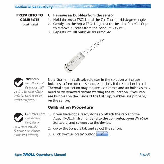
C Remove air bubbles from the sensor1. Hold the Aqua TROLL and the Cal Cup at a 45 degree angle.2. Gently tap the Aqua TROLL against the inside of the Cal Cup
to remove bubbles from the conductivity cell. 3. Repeat until all bubbles are removed.
Note: Sometimes dissolved gases in the solution will cause bubbles to form on the sensor, especially if the solution is cold. Thermal equilibrium may require extra time, and air bubbles may need to be removed before starting the calibration. If you can see bubbles on the inside of the Cal Cup, bubbles are probably on the sensor.
Calibration Procedure
1. If you have not already done so, attach the cable to the Aqua TROLL Instrument and to the computer, open Win-Situ Software, and connect to the device.
2. Go to the Sensors tab and select the sensor.
3. Clickthe“Calibrate”button .
PREPARING TO CALIBRATE (continued)
TIP: With the correct fill level, and the instrument held
at a 45° angle, the air bubble in the Cal Cup will not intrude into the conductivity sensor.
TIP: For best results when calibrating a completely dry
sensor, allow it to soak for 15 minutes in the calibration solution before proceeding.

Page 52Aqua TROLL Operator’s Manual
Section 5: Conductivity
4. In the next screen, select the Conductivity parameter and click Calibrate...
2. Select the sensor
3. Click Calibrate
4. Select Conductivity,click Calibrate...
1. Sensors tab

Page 53Aqua TROLL Operator’s Manual
After a review of the preparation steps the Conductivity Calibration screen appears.
5. Enter the Specific Conductivity of the calibration solution into the box next to µS/cm @25° C.
6. Click Start Calibration.
Software will monitor the conductivity and temperature readings, calculate the cell constant (sometimes called the “Kcell”),andinformyouwhentheresponsemeetsthecriteriafor Nominal Stability.
7. You can click Accept... at any time to continue. For best results, wait until Full Stability is reached. At that time, the next screen is displayed automatically.
8. Look at the Proposed Cell Constant before you Commit the value to the sensor. It should be in the range 0.98 to 1.02.
Section 5: Conductivity
TIP: “Delta” is the change in sensor response between
the last two readings. This enables you to follow the progress of the stabilization. However, deviation from the previous reading is not necessarily the best indicator of stability because the software evaluates longer-term trends.
CALIBRATION (continued)
TIP: The Write Defaults button restores the factory cell constant to the sensor.

Page 54Aqua TROLL Operator’s Manual
If the cell constant is out of range, the cause could be an air bubble, incomplete rinsing, sensor fouling, or other factors. Repeat the preparation and calibration with fresh cal solution.
9. When you are satisfied with the proposed cell constant, click Commit to write the calculated cell constant to the sensor.
10. If the Aqua TROLL will be deployed immediately, remove it from the Cal Cup, rinse it, discard the calibration solution, and reinstall the black nose cone. Otherwise, store it wet in the Cal Cup (in cal solution or water) for later deployment.
TIP: If the proposed cell constant is outside the range
0.98 – 1.02, check conditions and repeat the calibration.
Section 5: Conductivity
Nominal Stability vs. Full Stability
To meet the criteria for a valid calibration point, the change in sensor response is monitored over time. The software is looking for the calibration solution temperature and the sensor readings to settle over a specific time period. The criteria for Full Stability are designed to meet the published specifications. The criteria for Nominal Stability are designed to shorten the calibration time when an approximate calibration is acceptable.
TIP: A change from an earlier cell constant of 0.02
suggests that the calibration should be repeated.
CALIBRATION (continued)
Page 55Aqua TROLL Operator’s Manual
Section 5: Conductivity
Available ParametersThe Aqua TROLL Instrument can also calculate and record derived parameters as listed below.
For more information on measurement methodology, including the equations used to derive the calculated parameters, see the technicalnote“AquaTROLL200MeasurementMethodology”onthe In-Situ software/resource CD, or in the Downloads section of the In-Situ web site at www.In-Situ.com.
Actual ConductivityUnits: micro siemens per centimeter (µS/cm), default
milli siemens per centimeter (mS/cm)
Specific Conductivity A means of expressing what the actual conductivity of a solution would be at a standard reference temperature (25° C). Calculated from actual conductivity and temperature. The factory default coefficients calculate specific conductivity per Standard Methods 2510B.
Units: micro siemens per centimeter (µS/cm), default milli siemens per centimeter (mS/cm)
SalinityCalculated from actual conductivity and temperature. Units: Practical Salinity Units (PSU)
Total Dissolved Solids (TDS)Calculated from specific conductivity using a conversion factor (Default: 0.65).
The TDS conversion factor may be edited in Win-Situ as follows: Select the sensor on the Sensors tab, click Configure , in

Page 56Aqua TROLL Operator’s Manual
Section 5: Conductivity
the next screen select the Total Dissolved Solids parameter and click Configure... Enter a value between 0.001 and 10.000.
Units: parts per thousand (ppt), default parts per million (ppm)
ResistivityResistivity is the reciprocal (inverse) of the actual conductivity, which is useful when monitoring pure water. Units: ohms-cm
Density of WaterCalculated from salinity and temperature. Units: g/cm3
Shallow DeploymentWhen deploying the Aqua TROLL Instrument in shallow water, bubble formation on the conductivity sensor can create false readings. We recommend the following to minimize the formation of bubbles:4 Surface water: Gently agitate the instrument. Natural water
flowwillhelptopreventbubbles.4 Groundwaterwelloranylocationwithoutflowingwater,or
where the instrument cannot be seen: 1. Lower the Aqua TROLL until it is below the surface of
the water. (Tip: This can be determined if not visible by monitoring the pressure/depth readings.)
2. Allow the conductivity sensor to be thoroughly wetted (at least 30 seconds).
3. Briskly agitate up and down several times, while not taking the device above the water surface.
4. When the conductivity readings stabilize, the Aqua TROLL is ready for deployment.
TIP: Parameter configuration is not available if the device
is polling or has an active log.
TIP: Measured density values may be used to
dynamically compute specific gravity when measuring Level. See Win-Situ Help or Section 6 of this manual for more information.

Page 57Aqua TROLL Operator’s Manual
Maintenance and Recalibration The need to clean the sensor is determined by the site conditions, and the accuracy you want to obtain from the instrument. For example, when used in relatively clean water of low biological productivity, a conductivity sensor could maintain its accuracy specifications for several months. On the other hand, in water with a high potential for biological or mineral fouling, the sensor may need to be cleaned and recalibrated more often. Visual inspection and measurement results are the best indicators that a device needs service recalibration.
It is the user’s responsibility to develop and follow a maintenance program appropriate to the site. Most standard operating procedures (SOPs) instruct that the instrument be checked in a known standard at the end of a deployment. Calibration should always be checked after cleaning, and should be recalibrated when necessary.
For specific cleaning procedures, refer to the Care and Maintenance recommendations in Section 9.
Factory recalibration of the Aqua TROLL 200 Instrument should be performed every 12-18 months. Contact In-Situ Inc. as described on page 10.
Section 5: Conductivity

Page 58 Aqua TROLL Operator’s Manual
6 Pressure and Level
The Aqua TROLL 200 Instrument contains a pressure sensor. A pressure transducer senses changes in pressure, measured in force per square unit of surface area, exerted by water or other fluidonaninternalmedia-isolatedstraingauge.Commonmeasurement units are pounds per square inch (psi) or newtons per square meter (pascals).
Non-Vented (Absolute) vs. Vented (Gauged) Sen-sorsAnon-ventedor“absolute”pressuresensormeasuresallpressureforces exerted on the strain gauge, including atmospheric pressure. Its units are psia (poundspersquareinch“absolute”),measured with respect to zero pressure.
Non-vented pressure measurements are useful in vacuum testing, in short-term testing when atmospheric pressure would not be expected to change, in very deep aquifers where the effects of atmospheric pressure are negligible, and in unconfined aquifers that are open to the atmosphere.
Withventedor“gauged”pressuresensors,aventtubeinthecable applies atmospheric pressure to the back of the strain gauge. The basic unit for vented measurements is psig (pounds persquareinch“gauge”),measuredwithrespecttoatmospheric

Page 59Aqua TROLL Operator’s Manual
pressure. Vented sensors thus exclude the atmospheric or barometric pressure component.
This difference between absolute and gauged measurements may be represented by a simple equation:
Pgauge = Pabsolute – Patmosphere
Pressure, Depth, and LevelOutput options for pressure measurement are completely software-selectable. Each log configuration presents the following choices:• PressureinpsiorkPa• Depthinfeetormeters• WaterLevelwithareference(an“offset”)4 Surface Elevation: positive up4 Depth to Water (drawdown): positive down
For Depth and Level, the software presents additional options:• Thetypeofmeasurementyouintendtolog(the“output”)• TheLevelReferenceyouintendtouse• Thespecific gravity of the water in which the device will be
deployed:4 Choose a fixed value for fresh, brackish, or saline water, or4 Enter a custom specific gravity value, or4 Choose Fixed density with gravitational compensation for
a pressure-to-level conversion that compensates pressure readingsforfluiddensityandlocalgravitationalfactor(based on your latitude and elevation), or
4 Choose Dynamic density with gravitational compensation, which will allow the software to dynamically compute specific gravity using density measured by the conductivity sensor and local gravitational factor.
TIP: For more on the differences between Absolute
(non-vented) and Gauged (vented) sensors, see the technical note on the In-Situ software/resource CD, or www.in-situ.com.
Section 6: Pressure & Level

Page 60Aqua TROLL Operator’s Manual
Configuring Depth and LevelThis procedure stores the configuration settings in the Aqua TROLL Instrument. When setting up a log, the same options are presented.
1. While connected to the instrument in software, click the Sensors tab.
2. Select the sensor and click the Configure button .
TIP: When you configure level using the Sensors
tab, the settings are stored in the Aqua TROLL Instrument and are available for use in Modbus, SDI-12, and analog communications, as well as in Win-Situ. Different configurations may be selected when setting up a log.
Sensors tab
Configure button
Select the sensor
TIP: Go to the Home tab and stop polling
before configuring any sensor parameter.
Section 6: Pressure & Level
Page 61Aqua TROLL Operator’s Manual
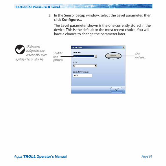
3. In the Sensor Setup window, select the Level parameter, then click Configure...
The Level parameter shown is the one currently stored in the device. This is the default or the most recent choice. You will have a chance to change the parameter later.
Click Configure...
Select the Level parameter
TIP: Parameter configuration is not available if the device
is polling or has an active log.
Section 6: Pressure & Level

Page 62Aqua TROLL Operator’s Manual
4. In the Level Setup Wizard, select the options you want. Each choice includes an illustration to assist you in selecting the output. For more information, see Help in Win-Situ 5 Software.
Section 6: Pressure & Level

Page 63Aqua TROLL Operator’s Manual
Pressure Sensor Calibration Factory RecalibrationPressure sensor accuracy can be adversely affected by improper care and handling, lightning strikes and similar surges, exceeding operating temperature and pressure limits, physical damage or abuse, as well as normal drift in the device’s electronic components. Aside from damage to the sensor, the need for factory recalibration is dependent upon the amount of drift a customer is willing to tolerate. Factory calibration every 12-18 months is recommended. Contact In-Situ Customer Service for information on the factory maintenance and calibration plan.
Field RecalibrationThe following procedure may be used, with caution, to set to zero the offset of a vented pressure sensor to correct for electronic drift. The drifted offset is visible when the sensor is in air and reading other than zero.
It is recommended you do not set to zero the offset if it is outside the specified accuracy of your pressure sensor, as shown in the table below. If the reading in air deviates from zero by more than the amounts shown, you may want to consider a factory recalibration.
Sensor Accuracy Acceptable Offset range (0°C to +50°C) from zero
5 psi ± 0.1% FS ± 0.005 psi 15 psi ± 0.1% FS ± 0.015 psi 30 psi ± 0.1% FS ± 0.03 psi 100 psi ± 0.1% FS ± 0.10 psi 300 psi ± 0.1% FS ± 0.30 psi 500 psi ± 0.1% FS ± 0.50 psi
TIP: In Level mode, any zero pressure offset is
corrected automatically. The field recalibration procedure is not necessary except when measuring pressure.
Section 6: Pressure & Level
Page 64Aqua TROLL Operator’s Manual
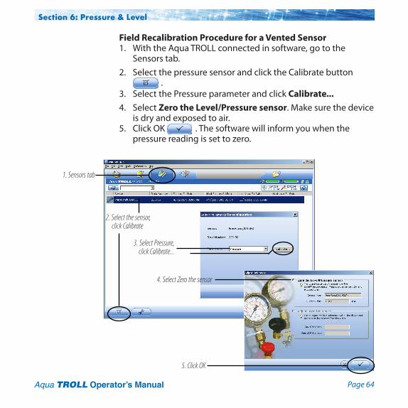
Field Recalibration Procedure for a Vented Sensor1. With the Aqua TROLL connected in software, go to the
Sensors tab. 2. Select the pressure sensor and click the Calibrate button
. 3. Select the Pressure parameter and click Calibrate...4. Select Zero the Level/Pressure sensor. Make sure the device
is dry and exposed to air.5. Click OK . The software will inform you when the
pressure reading is set to zero.
Section 6: Pressure & Level
2. Select the sensor, click Calibrate
3. Select Pressure,click Calibrate...
1. Sensors tab
4. Select Zero the sensor
5. Click OK
Page 65Aqua TROLL Operator’s Manual
Barometric Compensation of Non-Vented Pres-sure/Level DataWin-Situ® Baro Merge™ software can post-correct absolute (non-vented) level sensor data to eliminate barometric pressure from the measurements. Baro Merge provides three options:
• FixedCorrection–Asingleoffsetvalueisappliedtoallselected log data. Use this option if you know what the barometric pressure was during the log, and know that it did not change.
• ManualEntry–Specifytwoormorecorrectionvaluestoapply to the log data. Use this option if you know that barometric pressure changed during the log.
• BaroTROLL®Instrumentlogfile–Absolutelevelsensordataare corrected by barometric pressure values logged by an In-Situ BaroTROLL Instrument during the approximate time period.
Launching Baro Merge SoftwareBaro Merge may be opened as a stand-alone application from the program group In-Situ Inc., or accessed from Win-Situ’s Tools menu when both are installed on the same system.
InputIn the Fixed Correction and Manual Entry options, it is important to know the barometric pressure for the general time period covered by the log or logs you want to correct.
Baro Merge uses a Wizard-like interface consisting of three main steps:
1. Select the type of compensation/correction you intend to use.
Section 6: Pressure & Level

Page 66Aqua TROLL Operator’s Manual
2. Select the absolute (non-vented) log file or files you intend to correct. Baro Merge displays these automatically.
3. Click OK and the barometric compensation is applied.
OutputThe original log file is not changed. A new, corrected log file with thesamenameandpathiscreated.Theoriginal“.wsl”extensionisreplacedby“-BaroMerge.wsl”.
For help on using Win-Situ Baro Merge, press F1 at any Baro Merge screen.
For more detailed information on barometric compensation, see the technical notes on the In-Situ software/resource CD, or www.in-situ.com.
Section 6: Pressure & Level

Page 67 Aqua TROLL Operator’s Manual
7 Field Installation
Positioning the Vented Aqua TROLL 200 InstrumentFor unattended deployment, lower the Aqua TROLL 200 Instrument gently to approximately the desired depth. Position the instrument below the lowest anticipated water level, but not so low that its range might be exceeded at the highest anticipated level. Refer to the tables below for usable depth.
Range Usable Depth
psig kPa Meters Feet
5 34.5 3.5 11.5 15 103.4 11 35 30 206.8 21 69 100 689.5 70 231 300 2068 210 692 500 3447 351 1153
Vented Aqua TROLL Instrument Non-Vented Aqua TROLL Instrument
Range Effective Range* Usable Depth
psia psia kPa Meters Feet
30 15.5 106.9 10.9 35.8 100 85.5 589.5 60.0 197 300 285.5 1968 200.7 658.7 500 485.5 3347 341.3 1120
* At sea level (14.5 psi atmospheric pressure).
Do not let the instrument fall freely into the
water because it can damage the pressure sensor.
Page 68Aqua TROLL Operator’s Manual
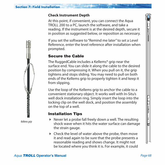
Check Instrument DepthAt this point, if convenient, you can connect the Aqua TROLL 200 to a PC, launch the software, and take a reading. If the instrument is at the desired depth, secure it in position as suggested below, or reposition as necessary.
Ifyousetthesoftwareto“Remindmelater”tosetaLevelReference, enter the level reference after installation when prompted.
Secure the CableThe RuggedCable includes a Kellems® grip near the surface end. You can slide it along the cable to the desired position by compressing it. When you pull on it, the grip tightens and stops sliding. You may need to pull on both ends of the Kellems grip to properly tighten it and keep it from slipping.
Use the loop of the Kellems grip to anchor the cable to a convenient stationary object. It works well with In-Situ’s well dock installation ring. Simply insert the loop into the locking clip on the well dock, and position the assembly on the top of a well.
Installation Tips4 Never let a probe fall freely down a well. The resulting
shock wave when it hits the water surface can damage the strain gauge.
4 Check the level of water above the probe, then move it and read again to be sure that the probe presents a reasonable reading and shows change. It might not be located where you think it is. For example, it could
Section 7: Field Installation
Kellems grip
Page 69Aqua TROLL Operator’s Manual
be wedged against the casing with a loop of cable hanging below it. A probe in such a position might become dislodged and move while logging, giving a false change in level. A secure placement is critical to accurate measurements.
4 Do not allow the vented cable to kink or bend. If the internal vent tube is obstructed, water level measurements can be adversely affected. The recommended minimum bend radius is 13.5 mm (0.54 in), which is twice the cable diameter.
4 For accurate measurements, the instrument should remain immobile while logging data.
4 Be sure the uphole cable end is capped—desiccant on the vented cable connector, soft dust cap on non-vented cable—and positioned above the highest anticipated water level. Avoidareasthatmayfloodwhenusingventedcable.
Stabilization TimeAllow the Aqua TROLL Instrument to stabilize to the water conditions for about an hour before logging data. A generous stabilization time is always desirable, especially in long-term deployments. Even though the cable is shielded, temperature stabiliza tion and stretching can cause apparent changes in the level reading. A completely dry conductivity sensor may need a few minutes settling time after initial immersion. If you expect to monitor conductivity and water levels at the highest accuracy possible for the instrument, allow stabilization time.
Shallow DeploymentWhen deploying the Aqua TROLL Instrument in shallow water, bubble formation on the conductivity sensor can create false readings. We recommend the following to minimize the formation of bubbles:
Section 7: Field Installation
TIP: Be sure to replace the desiccant before it appears
pink. Expired desiccant can allow moisture build up in the vent tube, causing a blockage resulting in inaccurate data.
Do not sub merge the cable connector; do not
immerse in any fluid.
The minimum bend radius for vented cable is
13.5 mm (0.54 in).
Do not deploy pressure transducers such
that ice may form on or near the sensor or cable connections. Ice formation is a powerful expansive force and may over-pressurize the sensor or otherwise cause damage. Any damage associated with ice formation is not covered by the warranty.
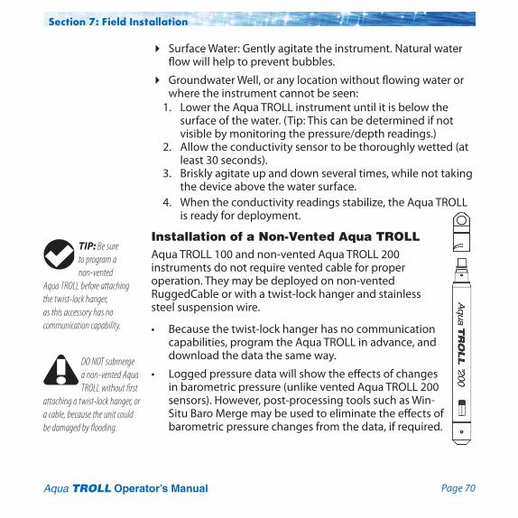
Page 70Aqua TROLL Operator’s Manual
4 Surface Water: Gently agitate the instrument. Natural water flowwillhelptopreventbubbles.
4 GroundwaterWell,oranylocationwithoutflowingwaterorwhere the instrument cannot be seen:
1. Lower the Aqua TROLL instrument until it is below the surface of the water. (Tip: This can be determined if not visible by monitoring the pressure/depth readings.)
2. Allow the conductivity sensor to be thoroughly wetted (at least 30 seconds).
3. Briskly agitate up and down several times, while not taking the device above the water surface.
4. When the conductivity readings stabilize, the Aqua TROLL is ready for deployment.
Installation of a Non-Vented Aqua TROLLAqua TROLL 100 and non-vented Aqua TROLL 200 instruments do not require vented cable for proper operation. They may be deployed on non-vented RuggedCable or with a twist-lock hanger and stainless steel suspension wire.
• Because the twist-lock hanger has no communication capabilities, program the Aqua TROLL in advance, and download the data the same way.
• Loggedpressuredatawillshowtheeffectsofchangesin barometric pressure (unlike vented Aqua TROLL 200 sensors). However, post-processing tools such as Win-Situ Baro Merge may be used to eliminate the effects of barometric pressure changes from the data, if required.
Section 7: Field Installation
TIP: Be sure to program a non-vented
Aqua TROLL before attaching the twist-lock hanger, as this accessory has no communication capability.
DO NOT submerge a non-vented Aqua TROLL without first
attaching a twist-lock hanger, or a cable, because the unit could be damaged by flooding.

Page 71 Aqua TROLL Operator’s Manual
8 Analog, SDI-12 and Modbus connections
The Aqua TROLL instrument may be connected to a controller or logger for communication via:• Analog4-20mA(providesaconfigurable4-20mAcurrent
loop output)• SDI-12• RS485Modbus• RS232toModbus(withacustomer-suppliedconverter)
Stripped-and-tinned cable has a female twist-lock connector on one end to connect with the Aqua TROLL Instrument. The uphole end terminates in bare wires for connection to a PLC or data logger.
A shorter cable ending in a male twist-lock connector to connect with RuggedCable is also available.

Page 72Aqua TROLL Operator’s Manual
Section 8: Analog, SDI-12, Modbus
Stripped-and-tinned cable with female connector
Aqua TROLL
PLC or Logger
Aqua TROLL
Short Stripped-and-tinned cable with male connector
RuggedCable
PLC or Logger
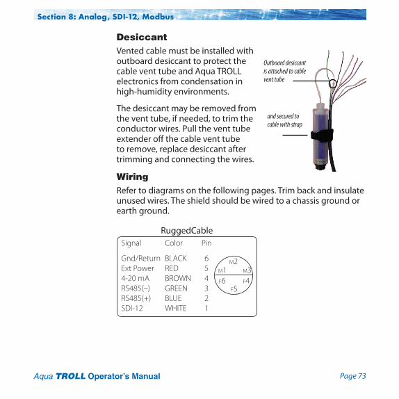
Page 73Aqua TROLL Operator’s Manual
DesiccantVented cable must be installed with outboard desiccant to protect the cable vent tube and Aqua TROLL electronics from condensation in high-humidity environments.
The desiccant may be removed from the vent tube, if needed, to trim the conductor wires. Pull the vent tube extender off the cable vent tube to remove, replace desiccant after trimming and connecting the wires.
WiringRefer to diagrams on the following pages. Trim back and insulate unused wires. The shield should be wired to a chassis ground or earth ground.
and secured to cable with strap
Outboard desiccant is attached to cable vent tube
RuggedCableSignal Color Pin
Gnd/Return BLACK 6 Ext Power RED 5 4-20 mA BROWN 4 RS485(–) GREEN 3 RS485(+) BLUE 2 SDI-12 WHITE 1
m2m1
f5
m3f6 f4
Section 8: Analog, SDI-12, Modbus

Page 74Aqua TROLL Operator’s Manual
ANALOG (4-20 mA) 3 WIRE
Aqua TROLL
4-20 mA BROWN
PLC or Data Logger
GND/RETURN BLACK
+
- signal
12-36 VDC
EXT PWR RED
Section 8: Analog, SDI-12, Modbus
Maximum cable length is 4000 ftAnalog must be enabled in Win-Situ 5 Software

Page 75Aqua TROLL Operator’s Manual
SDI-12 3 WIRE
EXT PWR RED
GND/RETURN BLACK
Data Logger
9.6-16 VDC
SDI-12 sensor
SDI-12 WHITE
RS485 (–) GREENRS485 (+) BLUE
Maximum cable length 200 ft
Section 8: Analog, SDI-12, Modbus

Page 76Aqua TROLL Operator’s Manual
MODBUS MASTERwith RS485 built in
* Optional but highly recommended
EXT PWR RED
GND/RETURN BLACK
Digital PLC
12-36 VDC*
Modbus Slave
RS485 (–) GREEN
RS485 (+) BLUE
Section 8: Analog, SDI-12, Modbus
Maximum cable length 4000 ft
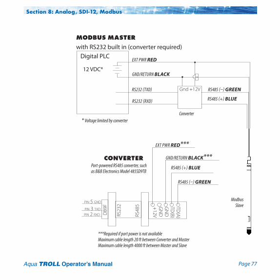
Page 77Aqua TROLL Operator’s Manual
RS48
5
RS23
2
***Required if port power is not availableMaximum cable length 20 ft between Converter and MasterMaximum cable length 4000 ft between Master and Slave
DB9
F TD(A)
TD(B)
GN
DG
ND
+12V
RS485 (+) BLUE
RS485 (–) GREEN
pin 5 gnd
pin 3 txd
pin 2 rxd
GND/RETURN BLACK***
EXT PWR RED***
CONVERTERPort-powered RS485 converter, such as B&B Electronics Model 485SD9TB
MODBUS MASTERwith RS232 built in (converter required)
* Voltage limited by converter
EXT PWR RED
GND/RETURN BLACK
Digital PLC
12 VDC*
Modbus Slave
RS485 (–) GREEN
RS232 (RXD)
RS232 (TXD)
Converter
Gnd +12V
RS485 (+) BLUE
Section 8: Analog, SDI-12, Modbus

Page 78Aqua TROLL Operator’s Manual
Power ConnectionsThe red wire provides power for all Aqua TROLL communication modes. Analog output is disabled by default. However, the 4-20 mA current loop output can be continuous in Modbus or SDI-12 mode as long as Modbus device register 49507 is set to 1. This can be done with a connection in Win-Situ by selecting the Device Setup tab, Analog Setup button, and enabling analog output.
CommunicationsThe device automatically switches between Modbus and SDI-12 modes depending on which of the two interfaces has activity. Modbus and SDI-12 cannot be used at the same time — whichever one is currently in use will block communication on the other.
Using Win-Situ SoftwareWin-Situ provides options for configuring analog/SDI-12 communications (Setup tab) and Modbus communications (File menu > Settings). In addition, the Aqua TROLL Instrument is capable of internal logging (programmed in Win-Situ) while participating in a Modbus, SDI-12, or analog network. However, Win-Situ cannot communicate with the Aqua TROLL Instrument while it is trans mitting Modbus, SDI-12, or analog data, and conversely, the instrument cannot receive or respond to Modbus, SDI-12, or analog commands while connected to a PC serial port.
Redundant Logging Feature• IfthePLCorrecordersomehowlosesdata,theAquaTROLL
data can be retrieved using Win-Situ.
Section 8: Analog, SDI-12, Modbus

Page 79Aqua TROLL Operator’s Manual
• IfthePLCorrecorderceasestofunctionduetopowerloss,the Aqua TROLL will continue to collect data using its own internal batteries and clock.
A port-powered RS485 converter like that shown for Modbus connections may be used for temporary connection of the Aqua TROLL to a serial port on a PC.
For More InformationFor additional information on Modbus and SDI-12 communications, including the SDI-12 commands and Modbus registers, see these In-Situ technical notes: • SDI-12CommandsandAquaTROLLResponses.• In-SituModbusCommunicationProtocol.
They are available on the In-Situ software/resource CD and at www.in-situ.com.
Section 8: Analog, SDI-12, Modbus
Page 80 Aqua TROLL Operator’s Manual
9 Care & MaintenanceOperating ConsiderationsThe Aqua TROLL Instrument has been designed to withstand harsh field conditions. However, as with any electronic instrument, it can be permanently damaged if used outside its operating specifications.
TemperatureThe Aqua TROLL temperature sensor operates within a temperature range of -5° to 50° C (23° to 122° F) in non-freezing fluid.
Pressure RangeThe Aqua TROLL 200 Instrument can withstand pressures of up to two times (2X) the rated range of the pressure sensor without damage, although it may not read correctly at such pressure. If the pressure range is exceeded by 3X, the pressure sensor will be destroyed.
Factory CalibrationAccuracy can be adversely affected by improper care and handling, lightning strikes and similar surges, exceeding operating temperature and pressure limits, physical damage or abuse. Factory calibration every 12-18 months is recommended. Contact In-Situ Customer Service for information on the factory maintenance and calibration plan.
Do not deploy pressure transducers such
that ice may form on or near the sensor or cable connections. Ice formation is a powerful expansive force and may over-pressurize the sensor or otherwise cause damage. Any damage associated with ice formation is not covered by the warranty.

Page 81Aqua TROLL Operator’s Manual
Section 9: Care & Maintenance
StorageStore the Aqua TROLL Instrument clean and dry. Place the protective red dust cap on the cable end, or store with cable attached to protect the connector pins and O-ring.
Store the instrument where it will not fall onto a hard surface.
Protect the instrument from temperature extremes. Store within a temperature range of -40° C to 65° C (-40° F to 149° F).
General MaintenanceTwist-Lock ConnectorsKeep the pins on all connectors free of dirt and moisture by using the soft protective dust cap when cable is not attached to an instrument.
Cable Vent Tube (Vented Cable)Vented cable ensures that atmospheric pressure is the reference pressure to the vented pressure sensor diaphragm. The vent tube should not be blocked, kinked, or otherwise obstructed. Such obstructions will cause barometric pressure to appear in measurements, and errors will be introduced due to thermal expansion and contraction of air within the vent tube and probe.
The recommended minimum bend radius is 13.5 mm (0.54 in), which is twice the cable diameter.
The minimum bend radius for vented cable is
13.5 mm (0.54 in).
Do not sub merge the cable connector; do not
immerse in any fluid.
TIP: Be sure to replace the desiccant before it appears
pink. Expired desiccant can allow moisture build up in the vent tube, causing a blockage resulting in inaccurate data.
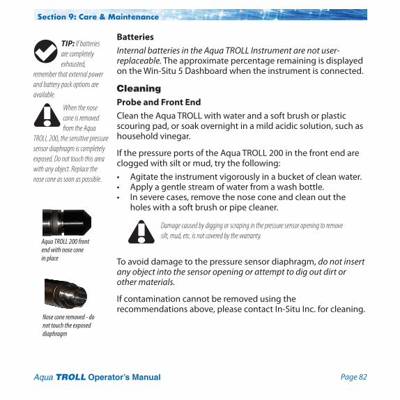
Page 82Aqua TROLL Operator’s Manual
BatteriesInternal batteries in the Aqua TROLL Instrument are not user-replaceable. The approximate percentage remaining is displayed on the Win-Situ 5 Dashboard when the instrument is connected.
CleaningProbe and Front EndClean the Aqua TROLL with water and a soft brush or plastic scouring pad, or soak overnight in a mild acidic solution, such as household vinegar.
If the pressure ports of the Aqua TROLL 200 in the front end are clogged with silt or mud, try the following:• Agitatetheinstrumentvigorouslyinabucketofcleanwater.• Applyagentlestreamofwaterfromawashbottle.• Inseverecases,removethenoseconeandcleanoutthe
holes with a soft brush or pipe cleaner.
To avoid damage to the pressure sensor diaphragm, do not insert any object into the sensor opening or attempt to dig out dirt or other materials.
If contamination cannot be removed using the recommendations above, please contact In-Situ Inc. for cleaning.
Section 9: Care & Maintenance
When the nose cone is removed from the Aqua
TROLL 200, the sensitive pressure sensor diaphragm is completely exposed. Do not touch this area with any object. Replace the nose cone as soon as possible.
Nose cone removed - do not touch the exposed diaphragm
Aqua TROLL 200 front end with nose cone in place
Damage caused by digging or scraping in the pressure sensor opening to remove silt, mud, etc. is not covered by the warranty.
TIP: If batteries are completely exhausted,
remember that external power and battery pack options are available.
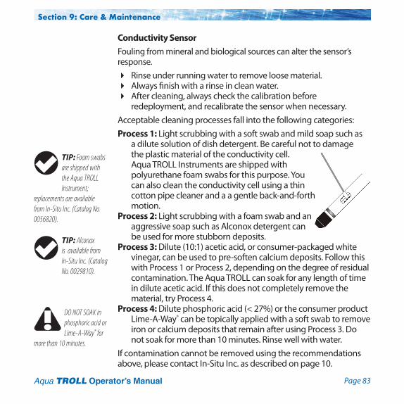
Page 83Aqua TROLL Operator’s Manual
Conductivity Sensor Fouling from mineral and biological sources can alter the sensor’s response. 4 Rinse under running water to remove loose material. 4 Always finish with a rinse in clean water.4 After cleaning, always check the calibration before
redeployment, and recalibrate the sensor when necessary. Acceptable cleaning processes fall into the following categories: Process 1: Light scrubbing with a soft swab and mild soap such as
a dilute solution of dish detergent. Be careful not to damage the plastic material of the conductivity cell. Aqua TROLL Instruments are shipped with polyurethane foam swabs for this purpose. You can also clean the conductivity cell using a thin cotton pipe cleaner and a a gentle back-and-forth motion.
Process 2: Light scrubbing with a foam swab and an aggressive soap such as Alconox detergent can be used for more stubborn deposits.
Process 3: Dilute (10:1) acetic acid, or consumer-packaged white vinegar, can be used to pre-soften calcium deposits. Follow this with Process 1 or Process 2, depending on the degree of residual contamination. The Aqua TROLL can soak for any length of time in dilute acetic acid. If this does not completely remove the material, try Process 4.
Process 4: Dilute phosphoric acid (< 27%) or the consumer product Lime-A-Way® can be topically applied with a soft swab to remove iron or calcium deposits that remain after using Process 3. Do not soak for more than 10 minutes. Rinse well with water.
If contamination cannot be removed using the recommendations above, please contact In-Situ Inc. as described on page 10.
Section 9: Care & Maintenance
TIP: Alconox is available from In-Situ Inc. (Catalog No. 0029810).
DO NOT SOAK in phosphoric acid or Lime-A-Way® for
more than 10 minutes.
TIP: Foam swabs are shipped with the Aqua TROLL Instrument;
replacements are available from In-Situ Inc. (Catalog No. 0056820).
Page 84 Aqua TROLL Operator’s Manual
TROUBLESHOOTING CONNECTIONS
Problem: Win-Situ 5 Software cannot connect to the Aqua TROLL instrument.
Probable Cause: The wrong COM port is selected, communication settings are incompatible, batteries are low, or cable connections are loose or dirty.
Suggested Remedy: Check the following:• Allcableconnectionsaretight,connectorsareclean
and dry.• Thecableissecurelyattachedtotheinstrument.• ThecorrectCOMportisselected(selectPreferences
menu > Comm Settings to check this).• ThecommunicationsettingsinWin-Situandinthe
Aqua TROLL match. To reset the device communication settingstotheserialdefaults,click“ResetallDevices”inthe Comm Settings dialog (Preferences menu > Comm Settings)
• Theinternalbatteryhasvoltageremainingorexternalpower is supplied.
10 Troubleshooting

Page 85Aqua TROLL Operator’s Manual
Section 10: TroubleshootingProblem: Real-time readings are in the wrong units.Probable Cause: Default units are being used.Suggested Remedy: Click the Sensors tab, select the sensor,
click the Configure button , and select the desired units for each parameter in the Sensor Setup window. Click OK .Besuretostop“polling”intheHomescreenbefore selecting units.
TROUBLESHOOTING DATA LOGS
Problem: Cannot add a new log.Probable Cause 1: Only one active log can reside in the device
at a time—an active log is a log that is Ready, Pending, Running, or Suspended as shown in the Status column of the Logging Tab.
Suggested Remedy: Stop or delete the log if possible. Alternatively, configure the new log after the active log is completed.
Probable Cause 2: The device has its maximum number of logs already stored—although this is not a likely cause for the Aqua TROLL 200, which has a capacity of 50 logs.
Suggested Remedy: Download, and then delete a log you are finished using. This will make room for an additional log on the device.
Problem: New log exceeds available memory (message from software).
Probable Cause: The log as configured would exceed the device memory.
Suggested Remedy: Edit the log and try these:• Selectalongersamplinginterval.• Ifavailable,selecttheWrapdataoption(currentdata
will overwrite older data when the memory is full).

Page 86Aqua TROLL Operator’s Manual
Section 10: Troubleshooting
• Foralogwithascheduledstart,selectNoneasthestopcondition, or select a stop time that is closer to the start time.
TROUBLESHOOTING PARAMETER CONFIGURATION
Problem: Cannot configure level or other parameters using the Configure button on the Sensors tab. The Sensor setup screen is shown, but the Configure... button is dim.
Probable Cause 1: The Aqua TROLL is actively polling (continually updating real-time readings) in the Home tab.
Suggested Remedy: Return to the Home tab and stop real-time readings by clicking .
Probable Cause 2: The Aqua TROLL has an active log—a log that is Ready, Pending, Running, or Suspended as shown in the Status column of the Logging Tab. Only one active log can reside in the device at a time.
Suggested Remedy: Stop or delete the log if possible. Alternatively, configure parameters after the log is completed.
TROUBLESHOOTING CONDUCTIVITY CALIBRATIONProblem: The calculated cell constant (Kcell) is lower than the
recommended range of 0.98 – 1.02.Probable Cause: The electrical resistance of the calibration
solution was lower than expected for the nominal value.Suggested Remedy: Check the following and then repeat the
calibration:• Visuallyinspectthesensorforthepresenceoffouling
(most likely conductive material, possibly a bio-film); clean as described in Section 9 of this manual.
• Ensurethecalibrationsolutionisnotcontaminated,mislabeled, or partially evaporated.

Page 87Aqua TROLL Operator’s Manual
• RinsetheAquaTROLLInstrumentandtheCalCupthoroughly with fresh calibration solution before calibrating.
Problem: The calculated cell constant (Kcell) is higher than the recommended range of 0.98 – 1.02.
Probable Cause: The electrical resistance of the calibration solution was higher than expected for the nominal value, or an air bubble was present in the sensing cell during calibration.
Suggested Remedy: Check the following and then repeat the calibration:• Visuallyinspectthesensorforthepresenceoffouling
(most likely an obstructing material or organism); clean as described in Section 9 of this manual.
• Ensurethecalibrationsolutionisnotcontaminated,mislabeled, or partially diluted.
• RinsetheAquaTROLLInstrumentandtheCalCupthoroughly with fresh calibration solution before calibrating.
• “Rollandtap”theAquaTROLLInstrumentintheCalCup to dispel air bubbles as described and illustrated in Section 5.
Section 10: Troubleshooting

Page 88 Aqua TROLL Operator’s Manual
Index
AAC adapter, 19Accessories, 20Active log, 44, 85, 86ActiveSync, 21Analog (4-20 mA) output
enabling, 78wiring, 74
BBarometric pressure
compensation, 65–66Batteries, external, 19Batteries, internal, 19, 82
CCable, 14
bend radius, 69, 81communication cables, 18Kellems grip, 68non-vented cable, 70stripped &
tinned, 16, 71, 72
suspension wire, 14, 17, 70TROLL Com, 46vented cable, 58, 69, 81
Calibrationconductivity, 42, 48, 86–87nominal stability, 54pressure sensor, 63
Cell constant, 48, 53, 86Cleaning, 57, 82
conductivity sensor, 83decontamination, 12
Clock, setting, 37Conductivity, 47–57
about, 47actual, 55available parameters, 55calibration, 42, 48, 86–87shallow
deployment, 56, 69specific, 55
Conductivity sensor, 42, 48cleaning, 83
DData
graphing, 45logging, 43viewing, 45
Decimal places displayed in Home screen, 36
Density, 59Depth, measuring, 59Desiccant, 17, 46, 69, 81
outboard, 73
FFactory recalibration, 57, 63
HHanger, twist-lock, 20, 70Home tab (Win-Situ), 35
customizing, 36
IInstallation, 67–69
accessories for, 20
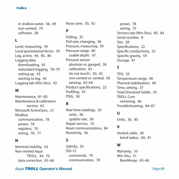
Page 89Aqua TROLL Operator’s Manual
Index
in shallow water, 56, 69non-vented, 70software, 28
LLevel, measuring, 59Local gravitational factor, 59Log, active, 44, 85, 86Logging data
downloading, 45redundant logging, 78–79setting up, 43starting to log, 45
Logging tab (Win-Situ), 43
MMaintenance, 81–83Maintenance & calibration
service, 63Microsoft ActiveSync, 21Modbus
communication, 78power, 78registers, 79wiring, 76, 77
NNominal stability, 54Non-vented Aqua
TROLL, 44, 70data correction, 65–66
Nose cone, 50, 82
PPolling, 35Poll rate, changing, 36Pressure, measuring, 59Pressure range, 80
usable depth, 67Pressure sensor
absolute vs. gauged, 58calibration, 63do not touch!, 50, 82non-vented vs. vented, 58zeroing, 63–64
Product specifications, 22Profiling, 35PSIG, 58
RReal-time readings, 35
units, 36update rate, 36
Repair service, 10Reset communications, 84Resistivity, 56
SSalinity, 55SDI-12
commands, 79communication, 78
power, 78wiring, 75
Sensors tab (Win-Situ), 60, 64Serial number, 8Site, 38Specifications, 22Specific conductivity, 55Specific gravity, 59Storage, 81
TTDS, 55Temperature range, 80Thermal stabilization, 69Time, setting, 37Total Dissolved Solids, 55TROLL Com
removing, 46Troubleshooting, 84–87
UUnits, 36, 85
VVented cable, 58
bend radius, 69, 81
WWarranty, 10Win-Situ, 21
BaroMerge, 65–66
Page 90Aqua TROLL Operator’s Manual
Index
Control Panel, 35Dashboard, 35exiting, 46installing, 28logging data, 43redundant logging, 78–79site, 38Software Manager, 28system requirements, 21tabs, 35Win-Situ Mobile, 21, 28
Wiringanalog (4-20 mA), 74Modbus RS232, 77Modbus RS485, 76SDI-12, 75
Page 91Aqua TROLL Operator’s Manual
Declaration of Conformity Manufacturer: In-Situ, Inc.
221 East Lincoln Avenue Fort Collins, CO 80524 USA Declares that the following product: Product name: Aqua TROLL Model: Aqua TROLL 200 Product Description: The Aqua TROLL 200 measures and logs level, temperature, and conductivity in
natural groundwater and surface water. is in compliance with the following Directives: 89/336/EEC for Electromagnetic Compatibility (EMC) Directive 73/23/EEC for Safety Directive and meets or exceeds the following international requirements and compliance standards:
• Immunity EN 61326:1997, Electric Equipment for Measurement, Control and Laboratory Use
• Emissions Class A requirements of EN 61326:1997, Electric Equipment for Measurement, Control
and Laboratory Use Supplementary Information: The device complies with the requirements of the EU Directives 89/336/EEC and 73/23/EEC, and the CE mark is affixed accordingly.
Todd Campbell New Product Development Program Manager In-Situ, Inc. October 17, 2006

Page 92Aqua TROLL Operator’s Manual
Page 93Aqua TROLL Operator’s Manual
Declaration of Conformity Manufacturer: In-Situ, Inc.
221 East Lincoln Avenue Fort Collins, CO 80524 USA Declares that the following product: Product name: TROLL Com Model: USB TROLL Com Product Description: RS485 to USB converter is in compliance with the following Directive 89/336/EEC for Electromagnetic Compatibility (EMC) Directive 73/23/EEC for Safety Directive and meets or exceeds the following international requirements and compliance standards:
• Immunity EN 61326, Electrical Equipment for Measurement, Control and Laboratory Use, Industrial
Location
• Emissions Class A requirements of EN 61326, Electrical Equipment for Measurement, Control and
Laboratory Use Supplementary Information: The device complies with the requirements of the EU Directives 89/336/EEC and 73/23/EEC, and the CE mark is affixed accordingly.
Todd Campbell New Product Development Program Manager In-Situ, Inc. June 17, 2006

0061340 rev. 006
Information subject to change without notice. In-Situ, In-Situ logo, Baro Merge, BaroTROLL, HERMIT, RDO, Pocket-Situ, RuggedCable, RuggedReader, TROLL, and Win-Situ are trademarks or registered trademarks of In-Situ Inc. © 2012. All rights reserved.
For more information, contact In-Situ Inc. 221 East Lincoln Avenue, Fort Collins, CO 80524 1-800-446-7488 (toll-free in U.S. & Canada)1-970-498-1500 (international & domestic)www.in-situ.com
The presence of the Waste Electrical and Electronic Equipment (WEEE) marking on the product indicates that the device is not to be disposed via the municipal waste collection system of any member state of the European Union.
For products under the requirement of WEEE directive, please contact your distributor or local In-Situ Inc. office for the proper decontamination information and take back program, which will facilitate the proper collection, treatment, recovery, recycling, and safe disposal of the device.